US8777993B2 - Laterally deflectable implant - Google Patents
Laterally deflectable implantDownload PDFInfo
- Publication number
- US8777993B2 US8777993B2US13/654,463US201213654463AUS8777993B2US 8777993 B2US8777993 B2US 8777993B2US 201213654463 AUS201213654463 AUS 201213654463AUS 8777993 B2US8777993 B2US 8777993B2
- Authority
- US
- United States
- Prior art keywords
- implant
- backbone
- deflectable piece
- deflectable
- proximal end
- Prior art date
- Legal status (The legal status is an assumption and is not a legal conclusion. Google has not performed a legal analysis and makes no representation as to the accuracy of the status listed.)
- Active, expires
Links
Images


Classifications
- A—HUMAN NECESSITIES
- A61—MEDICAL OR VETERINARY SCIENCE; HYGIENE
- A61F—FILTERS IMPLANTABLE INTO BLOOD VESSELS; PROSTHESES; DEVICES PROVIDING PATENCY TO, OR PREVENTING COLLAPSING OF, TUBULAR STRUCTURES OF THE BODY, e.g. STENTS; ORTHOPAEDIC, NURSING OR CONTRACEPTIVE DEVICES; FOMENTATION; TREATMENT OR PROTECTION OF EYES OR EARS; BANDAGES, DRESSINGS OR ABSORBENT PADS; FIRST-AID KITS
- A61F2/00—Filters implantable into blood vessels; Prostheses, i.e. artificial substitutes or replacements for parts of the body; Appliances for connecting them with the body; Devices providing patency to, or preventing collapsing of, tubular structures of the body, e.g. stents
- A61F2/02—Prostheses implantable into the body
- A61F2/30—Joints
- A61F2/44—Joints for the spine, e.g. vertebrae, spinal discs
- A61F2/442—Intervertebral or spinal discs, e.g. resilient
- A—HUMAN NECESSITIES
- A61—MEDICAL OR VETERINARY SCIENCE; HYGIENE
- A61B—DIAGNOSIS; SURGERY; IDENTIFICATION
- A61B17/00—Surgical instruments, devices or methods
- A61B17/34—Trocars; Puncturing needles
- A61B17/3472—Trocars; Puncturing needles for bones, e.g. intraosseus injections
- A—HUMAN NECESSITIES
- A61—MEDICAL OR VETERINARY SCIENCE; HYGIENE
- A61B—DIAGNOSIS; SURGERY; IDENTIFICATION
- A61B17/00—Surgical instruments, devices or methods
- A61B17/56—Surgical instruments or methods for treatment of bones or joints; Devices specially adapted therefor
- A61B17/58—Surgical instruments or methods for treatment of bones or joints; Devices specially adapted therefor for osteosynthesis, e.g. bone plates, screws or setting implements
- A61B17/88—Osteosynthesis instruments; Methods or means for implanting or extracting internal or external fixation devices
- A61B17/8802—Equipment for handling bone cement or other fluid fillers
- A61B17/8805—Equipment for handling bone cement or other fluid fillers for introducing fluid filler into bone or extracting it
- A61B17/8822—Equipment for handling bone cement or other fluid fillers for introducing fluid filler into bone or extracting it characterised by means facilitating expulsion of fluid from the introducer, e.g. a screw pump plunger, hydraulic force transmissions, application of vibrations or a vacuum
- A—HUMAN NECESSITIES
- A61—MEDICAL OR VETERINARY SCIENCE; HYGIENE
- A61F—FILTERS IMPLANTABLE INTO BLOOD VESSELS; PROSTHESES; DEVICES PROVIDING PATENCY TO, OR PREVENTING COLLAPSING OF, TUBULAR STRUCTURES OF THE BODY, e.g. STENTS; ORTHOPAEDIC, NURSING OR CONTRACEPTIVE DEVICES; FOMENTATION; TREATMENT OR PROTECTION OF EYES OR EARS; BANDAGES, DRESSINGS OR ABSORBENT PADS; FIRST-AID KITS
- A61F2/00—Filters implantable into blood vessels; Prostheses, i.e. artificial substitutes or replacements for parts of the body; Appliances for connecting them with the body; Devices providing patency to, or preventing collapsing of, tubular structures of the body, e.g. stents
- A61F2/02—Prostheses implantable into the body
- A61F2/30—Joints
- A61F2/44—Joints for the spine, e.g. vertebrae, spinal discs
- A61F2/4455—Joints for the spine, e.g. vertebrae, spinal discs for the fusion of spinal bodies, e.g. intervertebral fusion of adjacent spinal bodies, e.g. fusion cages
- A61F2/447—Joints for the spine, e.g. vertebrae, spinal discs for the fusion of spinal bodies, e.g. intervertebral fusion of adjacent spinal bodies, e.g. fusion cages substantially parallelepipedal, e.g. having a rectangular or trapezoidal cross-section
- A—HUMAN NECESSITIES
- A61—MEDICAL OR VETERINARY SCIENCE; HYGIENE
- A61F—FILTERS IMPLANTABLE INTO BLOOD VESSELS; PROSTHESES; DEVICES PROVIDING PATENCY TO, OR PREVENTING COLLAPSING OF, TUBULAR STRUCTURES OF THE BODY, e.g. STENTS; ORTHOPAEDIC, NURSING OR CONTRACEPTIVE DEVICES; FOMENTATION; TREATMENT OR PROTECTION OF EYES OR EARS; BANDAGES, DRESSINGS OR ABSORBENT PADS; FIRST-AID KITS
- A61F2/00—Filters implantable into blood vessels; Prostheses, i.e. artificial substitutes or replacements for parts of the body; Appliances for connecting them with the body; Devices providing patency to, or preventing collapsing of, tubular structures of the body, e.g. stents
- A61F2/02—Prostheses implantable into the body
- A61F2/30—Joints
- A61F2/46—Special tools for implanting artificial joints
- A61F2/4601—Special tools for implanting artificial joints for introducing bone substitute, for implanting bone graft implants or for compacting them in the bone cavity
- A—HUMAN NECESSITIES
- A61—MEDICAL OR VETERINARY SCIENCE; HYGIENE
- A61F—FILTERS IMPLANTABLE INTO BLOOD VESSELS; PROSTHESES; DEVICES PROVIDING PATENCY TO, OR PREVENTING COLLAPSING OF, TUBULAR STRUCTURES OF THE BODY, e.g. STENTS; ORTHOPAEDIC, NURSING OR CONTRACEPTIVE DEVICES; FOMENTATION; TREATMENT OR PROTECTION OF EYES OR EARS; BANDAGES, DRESSINGS OR ABSORBENT PADS; FIRST-AID KITS
- A61F2/00—Filters implantable into blood vessels; Prostheses, i.e. artificial substitutes or replacements for parts of the body; Appliances for connecting them with the body; Devices providing patency to, or preventing collapsing of, tubular structures of the body, e.g. stents
- A61F2/02—Prostheses implantable into the body
- A61F2/30—Joints
- A61F2/46—Special tools for implanting artificial joints
- A61F2/4603—Special tools for implanting artificial joints for insertion or extraction of endoprosthetic joints or of accessories thereof
- A61F2/4611—Special tools for implanting artificial joints for insertion or extraction of endoprosthetic joints or of accessories thereof of spinal prostheses
- A—HUMAN NECESSITIES
- A61—MEDICAL OR VETERINARY SCIENCE; HYGIENE
- A61B—DIAGNOSIS; SURGERY; IDENTIFICATION
- A61B17/00—Surgical instruments, devices or methods
- A61B17/56—Surgical instruments or methods for treatment of bones or joints; Devices specially adapted therefor
- A61B17/58—Surgical instruments or methods for treatment of bones or joints; Devices specially adapted therefor for osteosynthesis, e.g. bone plates, screws or setting implements
- A61B17/68—Internal fixation devices, including fasteners and spinal fixators, even if a part thereof projects from the skin
- A61B17/70—Spinal positioners or stabilisers, e.g. stabilisers comprising fluid filler in an implant
- A61B17/7062—Devices acting on, attached to, or simulating the effect of, vertebral processes, vertebral facets or ribs ; Tools for such devices
- A61B17/7065—Devices with changeable shape, e.g. collapsible or having retractable arms to aid implantation; Tools therefor
- A—HUMAN NECESSITIES
- A61—MEDICAL OR VETERINARY SCIENCE; HYGIENE
- A61F—FILTERS IMPLANTABLE INTO BLOOD VESSELS; PROSTHESES; DEVICES PROVIDING PATENCY TO, OR PREVENTING COLLAPSING OF, TUBULAR STRUCTURES OF THE BODY, e.g. STENTS; ORTHOPAEDIC, NURSING OR CONTRACEPTIVE DEVICES; FOMENTATION; TREATMENT OR PROTECTION OF EYES OR EARS; BANDAGES, DRESSINGS OR ABSORBENT PADS; FIRST-AID KITS
- A61F2/00—Filters implantable into blood vessels; Prostheses, i.e. artificial substitutes or replacements for parts of the body; Appliances for connecting them with the body; Devices providing patency to, or preventing collapsing of, tubular structures of the body, e.g. stents
- A61F2/02—Prostheses implantable into the body
- A61F2/30—Joints
- A61F2/30767—Special external or bone-contacting surface, e.g. coating for improving bone ingrowth
- A61F2/30771—Special external or bone-contacting surface, e.g. coating for improving bone ingrowth applied in original prostheses, e.g. holes or grooves
- A—HUMAN NECESSITIES
- A61—MEDICAL OR VETERINARY SCIENCE; HYGIENE
- A61F—FILTERS IMPLANTABLE INTO BLOOD VESSELS; PROSTHESES; DEVICES PROVIDING PATENCY TO, OR PREVENTING COLLAPSING OF, TUBULAR STRUCTURES OF THE BODY, e.g. STENTS; ORTHOPAEDIC, NURSING OR CONTRACEPTIVE DEVICES; FOMENTATION; TREATMENT OR PROTECTION OF EYES OR EARS; BANDAGES, DRESSINGS OR ABSORBENT PADS; FIRST-AID KITS
- A61F2/00—Filters implantable into blood vessels; Prostheses, i.e. artificial substitutes or replacements for parts of the body; Appliances for connecting them with the body; Devices providing patency to, or preventing collapsing of, tubular structures of the body, e.g. stents
- A61F2/02—Prostheses implantable into the body
- A61F2/30—Joints
- A61F2/46—Special tools for implanting artificial joints
- A—HUMAN NECESSITIES
- A61—MEDICAL OR VETERINARY SCIENCE; HYGIENE
- A61F—FILTERS IMPLANTABLE INTO BLOOD VESSELS; PROSTHESES; DEVICES PROVIDING PATENCY TO, OR PREVENTING COLLAPSING OF, TUBULAR STRUCTURES OF THE BODY, e.g. STENTS; ORTHOPAEDIC, NURSING OR CONTRACEPTIVE DEVICES; FOMENTATION; TREATMENT OR PROTECTION OF EYES OR EARS; BANDAGES, DRESSINGS OR ABSORBENT PADS; FIRST-AID KITS
- A61F2/00—Filters implantable into blood vessels; Prostheses, i.e. artificial substitutes or replacements for parts of the body; Appliances for connecting them with the body; Devices providing patency to, or preventing collapsing of, tubular structures of the body, e.g. stents
- A61F2/02—Prostheses implantable into the body
- A61F2/28—Bones
- A61F2002/2817—Bone stimulation by chemical reactions or by osteogenic or biological products for enhancing ossification, e.g. by bone morphogenetic or morphogenic proteins [BMP] or by transforming growth factors [TGF]
- A—HUMAN NECESSITIES
- A61—MEDICAL OR VETERINARY SCIENCE; HYGIENE
- A61F—FILTERS IMPLANTABLE INTO BLOOD VESSELS; PROSTHESES; DEVICES PROVIDING PATENCY TO, OR PREVENTING COLLAPSING OF, TUBULAR STRUCTURES OF THE BODY, e.g. STENTS; ORTHOPAEDIC, NURSING OR CONTRACEPTIVE DEVICES; FOMENTATION; TREATMENT OR PROTECTION OF EYES OR EARS; BANDAGES, DRESSINGS OR ABSORBENT PADS; FIRST-AID KITS
- A61F2/00—Filters implantable into blood vessels; Prostheses, i.e. artificial substitutes or replacements for parts of the body; Appliances for connecting them with the body; Devices providing patency to, or preventing collapsing of, tubular structures of the body, e.g. stents
- A61F2/02—Prostheses implantable into the body
- A61F2/28—Bones
- A61F2002/2835—Bone graft implants for filling a bony defect or an endoprosthesis cavity, e.g. by synthetic material or biological material
- A—HUMAN NECESSITIES
- A61—MEDICAL OR VETERINARY SCIENCE; HYGIENE
- A61F—FILTERS IMPLANTABLE INTO BLOOD VESSELS; PROSTHESES; DEVICES PROVIDING PATENCY TO, OR PREVENTING COLLAPSING OF, TUBULAR STRUCTURES OF THE BODY, e.g. STENTS; ORTHOPAEDIC, NURSING OR CONTRACEPTIVE DEVICES; FOMENTATION; TREATMENT OR PROTECTION OF EYES OR EARS; BANDAGES, DRESSINGS OR ABSORBENT PADS; FIRST-AID KITS
- A61F2/00—Filters implantable into blood vessels; Prostheses, i.e. artificial substitutes or replacements for parts of the body; Appliances for connecting them with the body; Devices providing patency to, or preventing collapsing of, tubular structures of the body, e.g. stents
- A61F2/02—Prostheses implantable into the body
- A61F2/30—Joints
- A61F2002/30001—Additional features of subject-matter classified in A61F2/28, A61F2/30 and subgroups thereof
- A61F2002/30003—Material related properties of the prosthesis or of a coating on the prosthesis
- A61F2002/3006—Properties of materials and coating materials
- A61F2002/30069—Properties of materials and coating materials elastomeric
- A—HUMAN NECESSITIES
- A61—MEDICAL OR VETERINARY SCIENCE; HYGIENE
- A61F—FILTERS IMPLANTABLE INTO BLOOD VESSELS; PROSTHESES; DEVICES PROVIDING PATENCY TO, OR PREVENTING COLLAPSING OF, TUBULAR STRUCTURES OF THE BODY, e.g. STENTS; ORTHOPAEDIC, NURSING OR CONTRACEPTIVE DEVICES; FOMENTATION; TREATMENT OR PROTECTION OF EYES OR EARS; BANDAGES, DRESSINGS OR ABSORBENT PADS; FIRST-AID KITS
- A61F2/00—Filters implantable into blood vessels; Prostheses, i.e. artificial substitutes or replacements for parts of the body; Appliances for connecting them with the body; Devices providing patency to, or preventing collapsing of, tubular structures of the body, e.g. stents
- A61F2/02—Prostheses implantable into the body
- A61F2/30—Joints
- A61F2002/30001—Additional features of subject-matter classified in A61F2/28, A61F2/30 and subgroups thereof
- A61F2002/30003—Material related properties of the prosthesis or of a coating on the prosthesis
- A61F2002/3006—Properties of materials and coating materials
- A61F2002/30092—Properties of materials and coating materials using shape memory or superelastic materials, e.g. nitinol
- A—HUMAN NECESSITIES
- A61—MEDICAL OR VETERINARY SCIENCE; HYGIENE
- A61F—FILTERS IMPLANTABLE INTO BLOOD VESSELS; PROSTHESES; DEVICES PROVIDING PATENCY TO, OR PREVENTING COLLAPSING OF, TUBULAR STRUCTURES OF THE BODY, e.g. STENTS; ORTHOPAEDIC, NURSING OR CONTRACEPTIVE DEVICES; FOMENTATION; TREATMENT OR PROTECTION OF EYES OR EARS; BANDAGES, DRESSINGS OR ABSORBENT PADS; FIRST-AID KITS
- A61F2/00—Filters implantable into blood vessels; Prostheses, i.e. artificial substitutes or replacements for parts of the body; Appliances for connecting them with the body; Devices providing patency to, or preventing collapsing of, tubular structures of the body, e.g. stents
- A61F2/02—Prostheses implantable into the body
- A61F2/30—Joints
- A61F2002/30001—Additional features of subject-matter classified in A61F2/28, A61F2/30 and subgroups thereof
- A61F2002/30108—Shapes
- A61F2002/3011—Cross-sections or two-dimensional shapes
- A61F2002/30112—Rounded shapes, e.g. with rounded corners
- A61F2002/30125—Rounded shapes, e.g. with rounded corners elliptical or oval
- A61F2002/30126—Rounded shapes, e.g. with rounded corners elliptical or oval oval-O-shaped
- A—HUMAN NECESSITIES
- A61—MEDICAL OR VETERINARY SCIENCE; HYGIENE
- A61F—FILTERS IMPLANTABLE INTO BLOOD VESSELS; PROSTHESES; DEVICES PROVIDING PATENCY TO, OR PREVENTING COLLAPSING OF, TUBULAR STRUCTURES OF THE BODY, e.g. STENTS; ORTHOPAEDIC, NURSING OR CONTRACEPTIVE DEVICES; FOMENTATION; TREATMENT OR PROTECTION OF EYES OR EARS; BANDAGES, DRESSINGS OR ABSORBENT PADS; FIRST-AID KITS
- A61F2/00—Filters implantable into blood vessels; Prostheses, i.e. artificial substitutes or replacements for parts of the body; Appliances for connecting them with the body; Devices providing patency to, or preventing collapsing of, tubular structures of the body, e.g. stents
- A61F2/02—Prostheses implantable into the body
- A61F2/30—Joints
- A61F2002/30001—Additional features of subject-matter classified in A61F2/28, A61F2/30 and subgroups thereof
- A61F2002/30108—Shapes
- A61F2002/3011—Cross-sections or two-dimensional shapes
- A61F2002/30138—Convex polygonal shapes
- A61F2002/30153—Convex polygonal shapes rectangular
- A—HUMAN NECESSITIES
- A61—MEDICAL OR VETERINARY SCIENCE; HYGIENE
- A61F—FILTERS IMPLANTABLE INTO BLOOD VESSELS; PROSTHESES; DEVICES PROVIDING PATENCY TO, OR PREVENTING COLLAPSING OF, TUBULAR STRUCTURES OF THE BODY, e.g. STENTS; ORTHOPAEDIC, NURSING OR CONTRACEPTIVE DEVICES; FOMENTATION; TREATMENT OR PROTECTION OF EYES OR EARS; BANDAGES, DRESSINGS OR ABSORBENT PADS; FIRST-AID KITS
- A61F2/00—Filters implantable into blood vessels; Prostheses, i.e. artificial substitutes or replacements for parts of the body; Appliances for connecting them with the body; Devices providing patency to, or preventing collapsing of, tubular structures of the body, e.g. stents
- A61F2/02—Prostheses implantable into the body
- A61F2/30—Joints
- A61F2002/30001—Additional features of subject-matter classified in A61F2/28, A61F2/30 and subgroups thereof
- A61F2002/30108—Shapes
- A61F2002/3011—Cross-sections or two-dimensional shapes
- A61F2002/30138—Convex polygonal shapes
- A61F2002/30156—Convex polygonal shapes triangular
- A—HUMAN NECESSITIES
- A61—MEDICAL OR VETERINARY SCIENCE; HYGIENE
- A61F—FILTERS IMPLANTABLE INTO BLOOD VESSELS; PROSTHESES; DEVICES PROVIDING PATENCY TO, OR PREVENTING COLLAPSING OF, TUBULAR STRUCTURES OF THE BODY, e.g. STENTS; ORTHOPAEDIC, NURSING OR CONTRACEPTIVE DEVICES; FOMENTATION; TREATMENT OR PROTECTION OF EYES OR EARS; BANDAGES, DRESSINGS OR ABSORBENT PADS; FIRST-AID KITS
- A61F2/00—Filters implantable into blood vessels; Prostheses, i.e. artificial substitutes or replacements for parts of the body; Appliances for connecting them with the body; Devices providing patency to, or preventing collapsing of, tubular structures of the body, e.g. stents
- A61F2/02—Prostheses implantable into the body
- A61F2/30—Joints
- A61F2002/30001—Additional features of subject-matter classified in A61F2/28, A61F2/30 and subgroups thereof
- A61F2002/30108—Shapes
- A61F2002/3011—Cross-sections or two-dimensional shapes
- A61F2002/30138—Convex polygonal shapes
- A61F2002/30158—Convex polygonal shapes trapezoidal
- A—HUMAN NECESSITIES
- A61—MEDICAL OR VETERINARY SCIENCE; HYGIENE
- A61F—FILTERS IMPLANTABLE INTO BLOOD VESSELS; PROSTHESES; DEVICES PROVIDING PATENCY TO, OR PREVENTING COLLAPSING OF, TUBULAR STRUCTURES OF THE BODY, e.g. STENTS; ORTHOPAEDIC, NURSING OR CONTRACEPTIVE DEVICES; FOMENTATION; TREATMENT OR PROTECTION OF EYES OR EARS; BANDAGES, DRESSINGS OR ABSORBENT PADS; FIRST-AID KITS
- A61F2/00—Filters implantable into blood vessels; Prostheses, i.e. artificial substitutes or replacements for parts of the body; Appliances for connecting them with the body; Devices providing patency to, or preventing collapsing of, tubular structures of the body, e.g. stents
- A61F2/02—Prostheses implantable into the body
- A61F2/30—Joints
- A61F2002/30001—Additional features of subject-matter classified in A61F2/28, A61F2/30 and subgroups thereof
- A61F2002/30108—Shapes
- A61F2002/3011—Cross-sections or two-dimensional shapes
- A61F2002/30182—Other shapes
- A61F2002/30187—D-shaped or half-disc-shaped
- A—HUMAN NECESSITIES
- A61—MEDICAL OR VETERINARY SCIENCE; HYGIENE
- A61F—FILTERS IMPLANTABLE INTO BLOOD VESSELS; PROSTHESES; DEVICES PROVIDING PATENCY TO, OR PREVENTING COLLAPSING OF, TUBULAR STRUCTURES OF THE BODY, e.g. STENTS; ORTHOPAEDIC, NURSING OR CONTRACEPTIVE DEVICES; FOMENTATION; TREATMENT OR PROTECTION OF EYES OR EARS; BANDAGES, DRESSINGS OR ABSORBENT PADS; FIRST-AID KITS
- A61F2/00—Filters implantable into blood vessels; Prostheses, i.e. artificial substitutes or replacements for parts of the body; Appliances for connecting them with the body; Devices providing patency to, or preventing collapsing of, tubular structures of the body, e.g. stents
- A61F2/02—Prostheses implantable into the body
- A61F2/30—Joints
- A61F2002/30001—Additional features of subject-matter classified in A61F2/28, A61F2/30 and subgroups thereof
- A61F2002/30108—Shapes
- A61F2002/30199—Three-dimensional shapes
- A61F2002/302—Three-dimensional shapes toroidal, e.g. rings
- A61F2002/30202—Three-dimensional shapes toroidal, e.g. rings half-tores
- A—HUMAN NECESSITIES
- A61—MEDICAL OR VETERINARY SCIENCE; HYGIENE
- A61F—FILTERS IMPLANTABLE INTO BLOOD VESSELS; PROSTHESES; DEVICES PROVIDING PATENCY TO, OR PREVENTING COLLAPSING OF, TUBULAR STRUCTURES OF THE BODY, e.g. STENTS; ORTHOPAEDIC, NURSING OR CONTRACEPTIVE DEVICES; FOMENTATION; TREATMENT OR PROTECTION OF EYES OR EARS; BANDAGES, DRESSINGS OR ABSORBENT PADS; FIRST-AID KITS
- A61F2/00—Filters implantable into blood vessels; Prostheses, i.e. artificial substitutes or replacements for parts of the body; Appliances for connecting them with the body; Devices providing patency to, or preventing collapsing of, tubular structures of the body, e.g. stents
- A61F2/02—Prostheses implantable into the body
- A61F2/30—Joints
- A61F2002/30001—Additional features of subject-matter classified in A61F2/28, A61F2/30 and subgroups thereof
- A61F2002/30108—Shapes
- A61F2002/30199—Three-dimensional shapes
- A61F2002/30261—Three-dimensional shapes parallelepipedal
- A61F2002/30266—Three-dimensional shapes parallelepipedal wedge-shaped parallelepipeds
- A—HUMAN NECESSITIES
- A61—MEDICAL OR VETERINARY SCIENCE; HYGIENE
- A61F—FILTERS IMPLANTABLE INTO BLOOD VESSELS; PROSTHESES; DEVICES PROVIDING PATENCY TO, OR PREVENTING COLLAPSING OF, TUBULAR STRUCTURES OF THE BODY, e.g. STENTS; ORTHOPAEDIC, NURSING OR CONTRACEPTIVE DEVICES; FOMENTATION; TREATMENT OR PROTECTION OF EYES OR EARS; BANDAGES, DRESSINGS OR ABSORBENT PADS; FIRST-AID KITS
- A61F2/00—Filters implantable into blood vessels; Prostheses, i.e. artificial substitutes or replacements for parts of the body; Appliances for connecting them with the body; Devices providing patency to, or preventing collapsing of, tubular structures of the body, e.g. stents
- A61F2/02—Prostheses implantable into the body
- A61F2/30—Joints
- A61F2002/30001—Additional features of subject-matter classified in A61F2/28, A61F2/30 and subgroups thereof
- A61F2002/30108—Shapes
- A61F2002/30199—Three-dimensional shapes
- A61F2002/30304—Three-dimensional shapes nose-shaped
- A—HUMAN NECESSITIES
- A61—MEDICAL OR VETERINARY SCIENCE; HYGIENE
- A61F—FILTERS IMPLANTABLE INTO BLOOD VESSELS; PROSTHESES; DEVICES PROVIDING PATENCY TO, OR PREVENTING COLLAPSING OF, TUBULAR STRUCTURES OF THE BODY, e.g. STENTS; ORTHOPAEDIC, NURSING OR CONTRACEPTIVE DEVICES; FOMENTATION; TREATMENT OR PROTECTION OF EYES OR EARS; BANDAGES, DRESSINGS OR ABSORBENT PADS; FIRST-AID KITS
- A61F2/00—Filters implantable into blood vessels; Prostheses, i.e. artificial substitutes or replacements for parts of the body; Appliances for connecting them with the body; Devices providing patency to, or preventing collapsing of, tubular structures of the body, e.g. stents
- A61F2/02—Prostheses implantable into the body
- A61F2/30—Joints
- A61F2002/30001—Additional features of subject-matter classified in A61F2/28, A61F2/30 and subgroups thereof
- A61F2002/30316—The prosthesis having different structural features at different locations within the same prosthesis; Connections between prosthetic parts; Special structural features of bone or joint prostheses not otherwise provided for
- A61F2002/30329—Connections or couplings between prosthetic parts, e.g. between modular parts; Connecting elements
- A61F2002/30331—Connections or couplings between prosthetic parts, e.g. between modular parts; Connecting elements made by longitudinally pushing a protrusion into a complementarily-shaped recess, e.g. held by friction fit
- A—HUMAN NECESSITIES
- A61—MEDICAL OR VETERINARY SCIENCE; HYGIENE
- A61F—FILTERS IMPLANTABLE INTO BLOOD VESSELS; PROSTHESES; DEVICES PROVIDING PATENCY TO, OR PREVENTING COLLAPSING OF, TUBULAR STRUCTURES OF THE BODY, e.g. STENTS; ORTHOPAEDIC, NURSING OR CONTRACEPTIVE DEVICES; FOMENTATION; TREATMENT OR PROTECTION OF EYES OR EARS; BANDAGES, DRESSINGS OR ABSORBENT PADS; FIRST-AID KITS
- A61F2/00—Filters implantable into blood vessels; Prostheses, i.e. artificial substitutes or replacements for parts of the body; Appliances for connecting them with the body; Devices providing patency to, or preventing collapsing of, tubular structures of the body, e.g. stents
- A61F2/02—Prostheses implantable into the body
- A61F2/30—Joints
- A61F2002/30001—Additional features of subject-matter classified in A61F2/28, A61F2/30 and subgroups thereof
- A61F2002/30316—The prosthesis having different structural features at different locations within the same prosthesis; Connections between prosthetic parts; Special structural features of bone or joint prostheses not otherwise provided for
- A61F2002/30329—Connections or couplings between prosthetic parts, e.g. between modular parts; Connecting elements
- A61F2002/30383—Connections or couplings between prosthetic parts, e.g. between modular parts; Connecting elements made by laterally inserting a protrusion, e.g. a rib into a complementarily-shaped groove
- A61F2002/3039—Connections or couplings between prosthetic parts, e.g. between modular parts; Connecting elements made by laterally inserting a protrusion, e.g. a rib into a complementarily-shaped groove with possibility of relative movement of the rib within the groove
- A61F2002/30398—Sliding
- A61F2002/30401—Sliding with additional means for preventing or locking said sliding
- A—HUMAN NECESSITIES
- A61—MEDICAL OR VETERINARY SCIENCE; HYGIENE
- A61F—FILTERS IMPLANTABLE INTO BLOOD VESSELS; PROSTHESES; DEVICES PROVIDING PATENCY TO, OR PREVENTING COLLAPSING OF, TUBULAR STRUCTURES OF THE BODY, e.g. STENTS; ORTHOPAEDIC, NURSING OR CONTRACEPTIVE DEVICES; FOMENTATION; TREATMENT OR PROTECTION OF EYES OR EARS; BANDAGES, DRESSINGS OR ABSORBENT PADS; FIRST-AID KITS
- A61F2/00—Filters implantable into blood vessels; Prostheses, i.e. artificial substitutes or replacements for parts of the body; Appliances for connecting them with the body; Devices providing patency to, or preventing collapsing of, tubular structures of the body, e.g. stents
- A61F2/02—Prostheses implantable into the body
- A61F2/30—Joints
- A61F2002/30001—Additional features of subject-matter classified in A61F2/28, A61F2/30 and subgroups thereof
- A61F2002/30316—The prosthesis having different structural features at different locations within the same prosthesis; Connections between prosthetic parts; Special structural features of bone or joint prostheses not otherwise provided for
- A61F2002/30329—Connections or couplings between prosthetic parts, e.g. between modular parts; Connecting elements
- A61F2002/30428—Connections or couplings between prosthetic parts, e.g. between modular parts; Connecting elements made by inserting a protrusion into a slot
- A61F2002/30431—Connections or couplings between prosthetic parts, e.g. between modular parts; Connecting elements made by inserting a protrusion into a slot made by first pushing a necked button longitudinally and then sliding it laterally within a keyhole slot
- A—HUMAN NECESSITIES
- A61—MEDICAL OR VETERINARY SCIENCE; HYGIENE
- A61F—FILTERS IMPLANTABLE INTO BLOOD VESSELS; PROSTHESES; DEVICES PROVIDING PATENCY TO, OR PREVENTING COLLAPSING OF, TUBULAR STRUCTURES OF THE BODY, e.g. STENTS; ORTHOPAEDIC, NURSING OR CONTRACEPTIVE DEVICES; FOMENTATION; TREATMENT OR PROTECTION OF EYES OR EARS; BANDAGES, DRESSINGS OR ABSORBENT PADS; FIRST-AID KITS
- A61F2/00—Filters implantable into blood vessels; Prostheses, i.e. artificial substitutes or replacements for parts of the body; Appliances for connecting them with the body; Devices providing patency to, or preventing collapsing of, tubular structures of the body, e.g. stents
- A61F2/02—Prostheses implantable into the body
- A61F2/30—Joints
- A61F2002/30001—Additional features of subject-matter classified in A61F2/28, A61F2/30 and subgroups thereof
- A61F2002/30316—The prosthesis having different structural features at different locations within the same prosthesis; Connections between prosthetic parts; Special structural features of bone or joint prostheses not otherwise provided for
- A61F2002/30329—Connections or couplings between prosthetic parts, e.g. between modular parts; Connecting elements
- A61F2002/30462—Connections or couplings between prosthetic parts, e.g. between modular parts; Connecting elements retained or tied with a rope, string, thread, wire or cable
- A—HUMAN NECESSITIES
- A61—MEDICAL OR VETERINARY SCIENCE; HYGIENE
- A61F—FILTERS IMPLANTABLE INTO BLOOD VESSELS; PROSTHESES; DEVICES PROVIDING PATENCY TO, OR PREVENTING COLLAPSING OF, TUBULAR STRUCTURES OF THE BODY, e.g. STENTS; ORTHOPAEDIC, NURSING OR CONTRACEPTIVE DEVICES; FOMENTATION; TREATMENT OR PROTECTION OF EYES OR EARS; BANDAGES, DRESSINGS OR ABSORBENT PADS; FIRST-AID KITS
- A61F2/00—Filters implantable into blood vessels; Prostheses, i.e. artificial substitutes or replacements for parts of the body; Appliances for connecting them with the body; Devices providing patency to, or preventing collapsing of, tubular structures of the body, e.g. stents
- A61F2/02—Prostheses implantable into the body
- A61F2/30—Joints
- A61F2002/30001—Additional features of subject-matter classified in A61F2/28, A61F2/30 and subgroups thereof
- A61F2002/30316—The prosthesis having different structural features at different locations within the same prosthesis; Connections between prosthetic parts; Special structural features of bone or joint prostheses not otherwise provided for
- A61F2002/30329—Connections or couplings between prosthetic parts, e.g. between modular parts; Connecting elements
- A61F2002/30471—Connections or couplings between prosthetic parts, e.g. between modular parts; Connecting elements connected by a hinged linkage mechanism, e.g. of the single-bar or multi-bar linkage type
- A—HUMAN NECESSITIES
- A61—MEDICAL OR VETERINARY SCIENCE; HYGIENE
- A61F—FILTERS IMPLANTABLE INTO BLOOD VESSELS; PROSTHESES; DEVICES PROVIDING PATENCY TO, OR PREVENTING COLLAPSING OF, TUBULAR STRUCTURES OF THE BODY, e.g. STENTS; ORTHOPAEDIC, NURSING OR CONTRACEPTIVE DEVICES; FOMENTATION; TREATMENT OR PROTECTION OF EYES OR EARS; BANDAGES, DRESSINGS OR ABSORBENT PADS; FIRST-AID KITS
- A61F2/00—Filters implantable into blood vessels; Prostheses, i.e. artificial substitutes or replacements for parts of the body; Appliances for connecting them with the body; Devices providing patency to, or preventing collapsing of, tubular structures of the body, e.g. stents
- A61F2/02—Prostheses implantable into the body
- A61F2/30—Joints
- A61F2002/30001—Additional features of subject-matter classified in A61F2/28, A61F2/30 and subgroups thereof
- A61F2002/30316—The prosthesis having different structural features at different locations within the same prosthesis; Connections between prosthetic parts; Special structural features of bone or joint prostheses not otherwise provided for
- A61F2002/30329—Connections or couplings between prosthetic parts, e.g. between modular parts; Connecting elements
- A61F2002/30476—Connections or couplings between prosthetic parts, e.g. between modular parts; Connecting elements locked by an additional locking mechanism
- A61F2002/30484—Mechanically expandable devices located on the first prosthetic part for locking into or onto the second prosthetic part
- A—HUMAN NECESSITIES
- A61—MEDICAL OR VETERINARY SCIENCE; HYGIENE
- A61F—FILTERS IMPLANTABLE INTO BLOOD VESSELS; PROSTHESES; DEVICES PROVIDING PATENCY TO, OR PREVENTING COLLAPSING OF, TUBULAR STRUCTURES OF THE BODY, e.g. STENTS; ORTHOPAEDIC, NURSING OR CONTRACEPTIVE DEVICES; FOMENTATION; TREATMENT OR PROTECTION OF EYES OR EARS; BANDAGES, DRESSINGS OR ABSORBENT PADS; FIRST-AID KITS
- A61F2/00—Filters implantable into blood vessels; Prostheses, i.e. artificial substitutes or replacements for parts of the body; Appliances for connecting them with the body; Devices providing patency to, or preventing collapsing of, tubular structures of the body, e.g. stents
- A61F2/02—Prostheses implantable into the body
- A61F2/30—Joints
- A61F2002/30001—Additional features of subject-matter classified in A61F2/28, A61F2/30 and subgroups thereof
- A61F2002/30316—The prosthesis having different structural features at different locations within the same prosthesis; Connections between prosthetic parts; Special structural features of bone or joint prostheses not otherwise provided for
- A61F2002/30329—Connections or couplings between prosthetic parts, e.g. between modular parts; Connecting elements
- A61F2002/30476—Connections or couplings between prosthetic parts, e.g. between modular parts; Connecting elements locked by an additional locking mechanism
- A61F2002/30492—Connections or couplings between prosthetic parts, e.g. between modular parts; Connecting elements locked by an additional locking mechanism using a locking pin
- A—HUMAN NECESSITIES
- A61—MEDICAL OR VETERINARY SCIENCE; HYGIENE
- A61F—FILTERS IMPLANTABLE INTO BLOOD VESSELS; PROSTHESES; DEVICES PROVIDING PATENCY TO, OR PREVENTING COLLAPSING OF, TUBULAR STRUCTURES OF THE BODY, e.g. STENTS; ORTHOPAEDIC, NURSING OR CONTRACEPTIVE DEVICES; FOMENTATION; TREATMENT OR PROTECTION OF EYES OR EARS; BANDAGES, DRESSINGS OR ABSORBENT PADS; FIRST-AID KITS
- A61F2/00—Filters implantable into blood vessels; Prostheses, i.e. artificial substitutes or replacements for parts of the body; Appliances for connecting them with the body; Devices providing patency to, or preventing collapsing of, tubular structures of the body, e.g. stents
- A61F2/02—Prostheses implantable into the body
- A61F2/30—Joints
- A61F2002/30001—Additional features of subject-matter classified in A61F2/28, A61F2/30 and subgroups thereof
- A61F2002/30316—The prosthesis having different structural features at different locations within the same prosthesis; Connections between prosthetic parts; Special structural features of bone or joint prostheses not otherwise provided for
- A61F2002/30329—Connections or couplings between prosthetic parts, e.g. between modular parts; Connecting elements
- A61F2002/30476—Connections or couplings between prosthetic parts, e.g. between modular parts; Connecting elements locked by an additional locking mechanism
- A61F2002/305—Snap connection
- A—HUMAN NECESSITIES
- A61—MEDICAL OR VETERINARY SCIENCE; HYGIENE
- A61F—FILTERS IMPLANTABLE INTO BLOOD VESSELS; PROSTHESES; DEVICES PROVIDING PATENCY TO, OR PREVENTING COLLAPSING OF, TUBULAR STRUCTURES OF THE BODY, e.g. STENTS; ORTHOPAEDIC, NURSING OR CONTRACEPTIVE DEVICES; FOMENTATION; TREATMENT OR PROTECTION OF EYES OR EARS; BANDAGES, DRESSINGS OR ABSORBENT PADS; FIRST-AID KITS
- A61F2/00—Filters implantable into blood vessels; Prostheses, i.e. artificial substitutes or replacements for parts of the body; Appliances for connecting them with the body; Devices providing patency to, or preventing collapsing of, tubular structures of the body, e.g. stents
- A61F2/02—Prostheses implantable into the body
- A61F2/30—Joints
- A61F2002/30001—Additional features of subject-matter classified in A61F2/28, A61F2/30 and subgroups thereof
- A61F2002/30316—The prosthesis having different structural features at different locations within the same prosthesis; Connections between prosthetic parts; Special structural features of bone or joint prostheses not otherwise provided for
- A61F2002/30329—Connections or couplings between prosthetic parts, e.g. between modular parts; Connecting elements
- A61F2002/30476—Connections or couplings between prosthetic parts, e.g. between modular parts; Connecting elements locked by an additional locking mechanism
- A61F2002/30507—Connections or couplings between prosthetic parts, e.g. between modular parts; Connecting elements locked by an additional locking mechanism using a threaded locking member, e.g. a locking screw or a set screw
- A—HUMAN NECESSITIES
- A61—MEDICAL OR VETERINARY SCIENCE; HYGIENE
- A61F—FILTERS IMPLANTABLE INTO BLOOD VESSELS; PROSTHESES; DEVICES PROVIDING PATENCY TO, OR PREVENTING COLLAPSING OF, TUBULAR STRUCTURES OF THE BODY, e.g. STENTS; ORTHOPAEDIC, NURSING OR CONTRACEPTIVE DEVICES; FOMENTATION; TREATMENT OR PROTECTION OF EYES OR EARS; BANDAGES, DRESSINGS OR ABSORBENT PADS; FIRST-AID KITS
- A61F2/00—Filters implantable into blood vessels; Prostheses, i.e. artificial substitutes or replacements for parts of the body; Appliances for connecting them with the body; Devices providing patency to, or preventing collapsing of, tubular structures of the body, e.g. stents
- A61F2/02—Prostheses implantable into the body
- A61F2/30—Joints
- A61F2002/30001—Additional features of subject-matter classified in A61F2/28, A61F2/30 and subgroups thereof
- A61F2002/30316—The prosthesis having different structural features at different locations within the same prosthesis; Connections between prosthetic parts; Special structural features of bone or joint prostheses not otherwise provided for
- A61F2002/30535—Special structural features of bone or joint prostheses not otherwise provided for
- A61F2002/30537—Special structural features of bone or joint prostheses not otherwise provided for adjustable
- A61F2002/30538—Special structural features of bone or joint prostheses not otherwise provided for adjustable for adjusting angular orientation
- A61F2002/3054—Special structural features of bone or joint prostheses not otherwise provided for adjustable for adjusting angular orientation about a connection axis or implantation axis for selecting any one of a plurality of radial orientations between two modular parts, e.g. Morse taper connections, at discrete positions, angular positions or continuous positions
- A—HUMAN NECESSITIES
- A61—MEDICAL OR VETERINARY SCIENCE; HYGIENE
- A61F—FILTERS IMPLANTABLE INTO BLOOD VESSELS; PROSTHESES; DEVICES PROVIDING PATENCY TO, OR PREVENTING COLLAPSING OF, TUBULAR STRUCTURES OF THE BODY, e.g. STENTS; ORTHOPAEDIC, NURSING OR CONTRACEPTIVE DEVICES; FOMENTATION; TREATMENT OR PROTECTION OF EYES OR EARS; BANDAGES, DRESSINGS OR ABSORBENT PADS; FIRST-AID KITS
- A61F2/00—Filters implantable into blood vessels; Prostheses, i.e. artificial substitutes or replacements for parts of the body; Appliances for connecting them with the body; Devices providing patency to, or preventing collapsing of, tubular structures of the body, e.g. stents
- A61F2/02—Prostheses implantable into the body
- A61F2/30—Joints
- A61F2002/30001—Additional features of subject-matter classified in A61F2/28, A61F2/30 and subgroups thereof
- A61F2002/30316—The prosthesis having different structural features at different locations within the same prosthesis; Connections between prosthetic parts; Special structural features of bone or joint prostheses not otherwise provided for
- A61F2002/30535—Special structural features of bone or joint prostheses not otherwise provided for
- A61F2002/30537—Special structural features of bone or joint prostheses not otherwise provided for adjustable
- A61F2002/3055—Special structural features of bone or joint prostheses not otherwise provided for adjustable for adjusting length
- A—HUMAN NECESSITIES
- A61—MEDICAL OR VETERINARY SCIENCE; HYGIENE
- A61F—FILTERS IMPLANTABLE INTO BLOOD VESSELS; PROSTHESES; DEVICES PROVIDING PATENCY TO, OR PREVENTING COLLAPSING OF, TUBULAR STRUCTURES OF THE BODY, e.g. STENTS; ORTHOPAEDIC, NURSING OR CONTRACEPTIVE DEVICES; FOMENTATION; TREATMENT OR PROTECTION OF EYES OR EARS; BANDAGES, DRESSINGS OR ABSORBENT PADS; FIRST-AID KITS
- A61F2/00—Filters implantable into blood vessels; Prostheses, i.e. artificial substitutes or replacements for parts of the body; Appliances for connecting them with the body; Devices providing patency to, or preventing collapsing of, tubular structures of the body, e.g. stents
- A61F2/02—Prostheses implantable into the body
- A61F2/30—Joints
- A61F2002/30001—Additional features of subject-matter classified in A61F2/28, A61F2/30 and subgroups thereof
- A61F2002/30316—The prosthesis having different structural features at different locations within the same prosthesis; Connections between prosthetic parts; Special structural features of bone or joint prostheses not otherwise provided for
- A61F2002/30535—Special structural features of bone or joint prostheses not otherwise provided for
- A61F2002/30537—Special structural features of bone or joint prostheses not otherwise provided for adjustable
- A61F2002/30556—Special structural features of bone or joint prostheses not otherwise provided for adjustable for adjusting thickness
- A—HUMAN NECESSITIES
- A61—MEDICAL OR VETERINARY SCIENCE; HYGIENE
- A61F—FILTERS IMPLANTABLE INTO BLOOD VESSELS; PROSTHESES; DEVICES PROVIDING PATENCY TO, OR PREVENTING COLLAPSING OF, TUBULAR STRUCTURES OF THE BODY, e.g. STENTS; ORTHOPAEDIC, NURSING OR CONTRACEPTIVE DEVICES; FOMENTATION; TREATMENT OR PROTECTION OF EYES OR EARS; BANDAGES, DRESSINGS OR ABSORBENT PADS; FIRST-AID KITS
- A61F2/00—Filters implantable into blood vessels; Prostheses, i.e. artificial substitutes or replacements for parts of the body; Appliances for connecting them with the body; Devices providing patency to, or preventing collapsing of, tubular structures of the body, e.g. stents
- A61F2/02—Prostheses implantable into the body
- A61F2/30—Joints
- A61F2002/30001—Additional features of subject-matter classified in A61F2/28, A61F2/30 and subgroups thereof
- A61F2002/30316—The prosthesis having different structural features at different locations within the same prosthesis; Connections between prosthetic parts; Special structural features of bone or joint prostheses not otherwise provided for
- A61F2002/30535—Special structural features of bone or joint prostheses not otherwise provided for
- A61F2002/30579—Special structural features of bone or joint prostheses not otherwise provided for with mechanically expandable devices, e.g. fixation devices
- A—HUMAN NECESSITIES
- A61—MEDICAL OR VETERINARY SCIENCE; HYGIENE
- A61F—FILTERS IMPLANTABLE INTO BLOOD VESSELS; PROSTHESES; DEVICES PROVIDING PATENCY TO, OR PREVENTING COLLAPSING OF, TUBULAR STRUCTURES OF THE BODY, e.g. STENTS; ORTHOPAEDIC, NURSING OR CONTRACEPTIVE DEVICES; FOMENTATION; TREATMENT OR PROTECTION OF EYES OR EARS; BANDAGES, DRESSINGS OR ABSORBENT PADS; FIRST-AID KITS
- A61F2/00—Filters implantable into blood vessels; Prostheses, i.e. artificial substitutes or replacements for parts of the body; Appliances for connecting them with the body; Devices providing patency to, or preventing collapsing of, tubular structures of the body, e.g. stents
- A61F2/02—Prostheses implantable into the body
- A61F2/30—Joints
- A61F2002/30001—Additional features of subject-matter classified in A61F2/28, A61F2/30 and subgroups thereof
- A61F2002/30316—The prosthesis having different structural features at different locations within the same prosthesis; Connections between prosthetic parts; Special structural features of bone or joint prostheses not otherwise provided for
- A61F2002/30535—Special structural features of bone or joint prostheses not otherwise provided for
- A61F2002/30593—Special structural features of bone or joint prostheses not otherwise provided for hollow
- A—HUMAN NECESSITIES
- A61—MEDICAL OR VETERINARY SCIENCE; HYGIENE
- A61F—FILTERS IMPLANTABLE INTO BLOOD VESSELS; PROSTHESES; DEVICES PROVIDING PATENCY TO, OR PREVENTING COLLAPSING OF, TUBULAR STRUCTURES OF THE BODY, e.g. STENTS; ORTHOPAEDIC, NURSING OR CONTRACEPTIVE DEVICES; FOMENTATION; TREATMENT OR PROTECTION OF EYES OR EARS; BANDAGES, DRESSINGS OR ABSORBENT PADS; FIRST-AID KITS
- A61F2/00—Filters implantable into blood vessels; Prostheses, i.e. artificial substitutes or replacements for parts of the body; Appliances for connecting them with the body; Devices providing patency to, or preventing collapsing of, tubular structures of the body, e.g. stents
- A61F2/02—Prostheses implantable into the body
- A61F2/30—Joints
- A61F2002/30001—Additional features of subject-matter classified in A61F2/28, A61F2/30 and subgroups thereof
- A61F2002/30316—The prosthesis having different structural features at different locations within the same prosthesis; Connections between prosthetic parts; Special structural features of bone or joint prostheses not otherwise provided for
- A61F2002/30535—Special structural features of bone or joint prostheses not otherwise provided for
- A61F2002/30601—Special structural features of bone or joint prostheses not otherwise provided for telescopic
- A—HUMAN NECESSITIES
- A61—MEDICAL OR VETERINARY SCIENCE; HYGIENE
- A61F—FILTERS IMPLANTABLE INTO BLOOD VESSELS; PROSTHESES; DEVICES PROVIDING PATENCY TO, OR PREVENTING COLLAPSING OF, TUBULAR STRUCTURES OF THE BODY, e.g. STENTS; ORTHOPAEDIC, NURSING OR CONTRACEPTIVE DEVICES; FOMENTATION; TREATMENT OR PROTECTION OF EYES OR EARS; BANDAGES, DRESSINGS OR ABSORBENT PADS; FIRST-AID KITS
- A61F2/00—Filters implantable into blood vessels; Prostheses, i.e. artificial substitutes or replacements for parts of the body; Appliances for connecting them with the body; Devices providing patency to, or preventing collapsing of, tubular structures of the body, e.g. stents
- A61F2/02—Prostheses implantable into the body
- A61F2/30—Joints
- A61F2002/30001—Additional features of subject-matter classified in A61F2/28, A61F2/30 and subgroups thereof
- A61F2002/30621—Features concerning the anatomical functioning or articulation of the prosthetic joint
- A61F2002/30622—Implant for fusing a joint or bone material
- A—HUMAN NECESSITIES
- A61—MEDICAL OR VETERINARY SCIENCE; HYGIENE
- A61F—FILTERS IMPLANTABLE INTO BLOOD VESSELS; PROSTHESES; DEVICES PROVIDING PATENCY TO, OR PREVENTING COLLAPSING OF, TUBULAR STRUCTURES OF THE BODY, e.g. STENTS; ORTHOPAEDIC, NURSING OR CONTRACEPTIVE DEVICES; FOMENTATION; TREATMENT OR PROTECTION OF EYES OR EARS; BANDAGES, DRESSINGS OR ABSORBENT PADS; FIRST-AID KITS
- A61F2/00—Filters implantable into blood vessels; Prostheses, i.e. artificial substitutes or replacements for parts of the body; Appliances for connecting them with the body; Devices providing patency to, or preventing collapsing of, tubular structures of the body, e.g. stents
- A61F2/02—Prostheses implantable into the body
- A61F2/30—Joints
- A61F2002/30001—Additional features of subject-matter classified in A61F2/28, A61F2/30 and subgroups thereof
- A61F2002/30621—Features concerning the anatomical functioning or articulation of the prosthetic joint
- A61F2002/30624—Hinged joint, e.g. with transverse axle restricting the movement
- A—HUMAN NECESSITIES
- A61—MEDICAL OR VETERINARY SCIENCE; HYGIENE
- A61F—FILTERS IMPLANTABLE INTO BLOOD VESSELS; PROSTHESES; DEVICES PROVIDING PATENCY TO, OR PREVENTING COLLAPSING OF, TUBULAR STRUCTURES OF THE BODY, e.g. STENTS; ORTHOPAEDIC, NURSING OR CONTRACEPTIVE DEVICES; FOMENTATION; TREATMENT OR PROTECTION OF EYES OR EARS; BANDAGES, DRESSINGS OR ABSORBENT PADS; FIRST-AID KITS
- A61F2/00—Filters implantable into blood vessels; Prostheses, i.e. artificial substitutes or replacements for parts of the body; Appliances for connecting them with the body; Devices providing patency to, or preventing collapsing of, tubular structures of the body, e.g. stents
- A61F2/02—Prostheses implantable into the body
- A61F2/30—Joints
- A61F2/30767—Special external or bone-contacting surface, e.g. coating for improving bone ingrowth
- A61F2/30771—Special external or bone-contacting surface, e.g. coating for improving bone ingrowth applied in original prostheses, e.g. holes or grooves
- A61F2002/30772—Apertures or holes, e.g. of circular cross section
- A61F2002/30784—Plurality of holes
- A61F2002/30785—Plurality of holes parallel
- A—HUMAN NECESSITIES
- A61—MEDICAL OR VETERINARY SCIENCE; HYGIENE
- A61F—FILTERS IMPLANTABLE INTO BLOOD VESSELS; PROSTHESES; DEVICES PROVIDING PATENCY TO, OR PREVENTING COLLAPSING OF, TUBULAR STRUCTURES OF THE BODY, e.g. STENTS; ORTHOPAEDIC, NURSING OR CONTRACEPTIVE DEVICES; FOMENTATION; TREATMENT OR PROTECTION OF EYES OR EARS; BANDAGES, DRESSINGS OR ABSORBENT PADS; FIRST-AID KITS
- A61F2/00—Filters implantable into blood vessels; Prostheses, i.e. artificial substitutes or replacements for parts of the body; Appliances for connecting them with the body; Devices providing patency to, or preventing collapsing of, tubular structures of the body, e.g. stents
- A61F2/02—Prostheses implantable into the body
- A61F2/30—Joints
- A61F2/30767—Special external or bone-contacting surface, e.g. coating for improving bone ingrowth
- A61F2/30771—Special external or bone-contacting surface, e.g. coating for improving bone ingrowth applied in original prostheses, e.g. holes or grooves
- A61F2002/30904—Special external or bone-contacting surface, e.g. coating for improving bone ingrowth applied in original prostheses, e.g. holes or grooves serrated profile, i.e. saw-toothed
- A—HUMAN NECESSITIES
- A61—MEDICAL OR VETERINARY SCIENCE; HYGIENE
- A61F—FILTERS IMPLANTABLE INTO BLOOD VESSELS; PROSTHESES; DEVICES PROVIDING PATENCY TO, OR PREVENTING COLLAPSING OF, TUBULAR STRUCTURES OF THE BODY, e.g. STENTS; ORTHOPAEDIC, NURSING OR CONTRACEPTIVE DEVICES; FOMENTATION; TREATMENT OR PROTECTION OF EYES OR EARS; BANDAGES, DRESSINGS OR ABSORBENT PADS; FIRST-AID KITS
- A61F2/00—Filters implantable into blood vessels; Prostheses, i.e. artificial substitutes or replacements for parts of the body; Appliances for connecting them with the body; Devices providing patency to, or preventing collapsing of, tubular structures of the body, e.g. stents
- A61F2/02—Prostheses implantable into the body
- A61F2/30—Joints
- A61F2/44—Joints for the spine, e.g. vertebrae, spinal discs
- A61F2002/4415—Joints for the spine, e.g. vertebrae, spinal discs elements of the prosthesis being arranged in a chain like manner
- A—HUMAN NECESSITIES
- A61—MEDICAL OR VETERINARY SCIENCE; HYGIENE
- A61F—FILTERS IMPLANTABLE INTO BLOOD VESSELS; PROSTHESES; DEVICES PROVIDING PATENCY TO, OR PREVENTING COLLAPSING OF, TUBULAR STRUCTURES OF THE BODY, e.g. STENTS; ORTHOPAEDIC, NURSING OR CONTRACEPTIVE DEVICES; FOMENTATION; TREATMENT OR PROTECTION OF EYES OR EARS; BANDAGES, DRESSINGS OR ABSORBENT PADS; FIRST-AID KITS
- A61F2/00—Filters implantable into blood vessels; Prostheses, i.e. artificial substitutes or replacements for parts of the body; Appliances for connecting them with the body; Devices providing patency to, or preventing collapsing of, tubular structures of the body, e.g. stents
- A61F2/02—Prostheses implantable into the body
- A61F2/30—Joints
- A61F2/44—Joints for the spine, e.g. vertebrae, spinal discs
- A61F2002/448—Joints for the spine, e.g. vertebrae, spinal discs comprising multiple adjacent spinal implants within the same intervertebral space or within the same vertebra, e.g. comprising two adjacent spinal implants
- A—HUMAN NECESSITIES
- A61—MEDICAL OR VETERINARY SCIENCE; HYGIENE
- A61F—FILTERS IMPLANTABLE INTO BLOOD VESSELS; PROSTHESES; DEVICES PROVIDING PATENCY TO, OR PREVENTING COLLAPSING OF, TUBULAR STRUCTURES OF THE BODY, e.g. STENTS; ORTHOPAEDIC, NURSING OR CONTRACEPTIVE DEVICES; FOMENTATION; TREATMENT OR PROTECTION OF EYES OR EARS; BANDAGES, DRESSINGS OR ABSORBENT PADS; FIRST-AID KITS
- A61F2/00—Filters implantable into blood vessels; Prostheses, i.e. artificial substitutes or replacements for parts of the body; Appliances for connecting them with the body; Devices providing patency to, or preventing collapsing of, tubular structures of the body, e.g. stents
- A61F2/02—Prostheses implantable into the body
- A61F2/30—Joints
- A61F2/46—Special tools for implanting artificial joints
- A61F2/4603—Special tools for implanting artificial joints for insertion or extraction of endoprosthetic joints or of accessories thereof
- A61F2002/4625—Special tools for implanting artificial joints for insertion or extraction of endoprosthetic joints or of accessories thereof with relative movement between parts of the instrument during use
- A61F2002/4627—Special tools for implanting artificial joints for insertion or extraction of endoprosthetic joints or of accessories thereof with relative movement between parts of the instrument during use with linear motion along or rotating motion about the instrument axis or the implantation direction, e.g. telescopic, along a guiding rod, screwing inside the instrument
- A—HUMAN NECESSITIES
- A61—MEDICAL OR VETERINARY SCIENCE; HYGIENE
- A61F—FILTERS IMPLANTABLE INTO BLOOD VESSELS; PROSTHESES; DEVICES PROVIDING PATENCY TO, OR PREVENTING COLLAPSING OF, TUBULAR STRUCTURES OF THE BODY, e.g. STENTS; ORTHOPAEDIC, NURSING OR CONTRACEPTIVE DEVICES; FOMENTATION; TREATMENT OR PROTECTION OF EYES OR EARS; BANDAGES, DRESSINGS OR ABSORBENT PADS; FIRST-AID KITS
- A61F2/00—Filters implantable into blood vessels; Prostheses, i.e. artificial substitutes or replacements for parts of the body; Appliances for connecting them with the body; Devices providing patency to, or preventing collapsing of, tubular structures of the body, e.g. stents
- A61F2/02—Prostheses implantable into the body
- A61F2/30—Joints
- A61F2/46—Special tools for implanting artificial joints
- A61F2/4603—Special tools for implanting artificial joints for insertion or extraction of endoprosthetic joints or of accessories thereof
- A61F2002/4625—Special tools for implanting artificial joints for insertion or extraction of endoprosthetic joints or of accessories thereof with relative movement between parts of the instrument during use
- A61F2002/4628—Special tools for implanting artificial joints for insertion or extraction of endoprosthetic joints or of accessories thereof with relative movement between parts of the instrument during use with linear motion along or rotating motion about an axis transverse to the instrument axis or to the implantation direction, e.g. clamping
- A—HUMAN NECESSITIES
- A61—MEDICAL OR VETERINARY SCIENCE; HYGIENE
- A61F—FILTERS IMPLANTABLE INTO BLOOD VESSELS; PROSTHESES; DEVICES PROVIDING PATENCY TO, OR PREVENTING COLLAPSING OF, TUBULAR STRUCTURES OF THE BODY, e.g. STENTS; ORTHOPAEDIC, NURSING OR CONTRACEPTIVE DEVICES; FOMENTATION; TREATMENT OR PROTECTION OF EYES OR EARS; BANDAGES, DRESSINGS OR ABSORBENT PADS; FIRST-AID KITS
- A61F2/00—Filters implantable into blood vessels; Prostheses, i.e. artificial substitutes or replacements for parts of the body; Appliances for connecting them with the body; Devices providing patency to, or preventing collapsing of, tubular structures of the body, e.g. stents
- A61F2/02—Prostheses implantable into the body
- A61F2/30—Joints
- A61F2/46—Special tools for implanting artificial joints
- A61F2/4603—Special tools for implanting artificial joints for insertion or extraction of endoprosthetic joints or of accessories thereof
- A61F2002/4629—Special tools for implanting artificial joints for insertion or extraction of endoprosthetic joints or of accessories thereof connected to the endoprosthesis or implant via a threaded connection
- A—HUMAN NECESSITIES
- A61—MEDICAL OR VETERINARY SCIENCE; HYGIENE
- A61F—FILTERS IMPLANTABLE INTO BLOOD VESSELS; PROSTHESES; DEVICES PROVIDING PATENCY TO, OR PREVENTING COLLAPSING OF, TUBULAR STRUCTURES OF THE BODY, e.g. STENTS; ORTHOPAEDIC, NURSING OR CONTRACEPTIVE DEVICES; FOMENTATION; TREATMENT OR PROTECTION OF EYES OR EARS; BANDAGES, DRESSINGS OR ABSORBENT PADS; FIRST-AID KITS
- A61F2/00—Filters implantable into blood vessels; Prostheses, i.e. artificial substitutes or replacements for parts of the body; Appliances for connecting them with the body; Devices providing patency to, or preventing collapsing of, tubular structures of the body, e.g. stents
- A61F2/02—Prostheses implantable into the body
- A61F2/30—Joints
- A61F2/46—Special tools for implanting artificial joints
- A61F2002/4631—Special tools for implanting artificial joints the prosthesis being specially adapted for being cemented
- A—HUMAN NECESSITIES
- A61—MEDICAL OR VETERINARY SCIENCE; HYGIENE
- A61F—FILTERS IMPLANTABLE INTO BLOOD VESSELS; PROSTHESES; DEVICES PROVIDING PATENCY TO, OR PREVENTING COLLAPSING OF, TUBULAR STRUCTURES OF THE BODY, e.g. STENTS; ORTHOPAEDIC, NURSING OR CONTRACEPTIVE DEVICES; FOMENTATION; TREATMENT OR PROTECTION OF EYES OR EARS; BANDAGES, DRESSINGS OR ABSORBENT PADS; FIRST-AID KITS
- A61F2310/00—Prostheses classified in A61F2/28 or A61F2/30 - A61F2/44 being constructed from or coated with a particular material
- A61F2310/00005—The prosthesis being constructed from a particular material
- A61F2310/00011—Metals or alloys
- A61F2310/00017—Iron- or Fe-based alloys, e.g. stainless steel
- A—HUMAN NECESSITIES
- A61—MEDICAL OR VETERINARY SCIENCE; HYGIENE
- A61F—FILTERS IMPLANTABLE INTO BLOOD VESSELS; PROSTHESES; DEVICES PROVIDING PATENCY TO, OR PREVENTING COLLAPSING OF, TUBULAR STRUCTURES OF THE BODY, e.g. STENTS; ORTHOPAEDIC, NURSING OR CONTRACEPTIVE DEVICES; FOMENTATION; TREATMENT OR PROTECTION OF EYES OR EARS; BANDAGES, DRESSINGS OR ABSORBENT PADS; FIRST-AID KITS
- A61F2310/00—Prostheses classified in A61F2/28 or A61F2/30 - A61F2/44 being constructed from or coated with a particular material
- A61F2310/00005—The prosthesis being constructed from a particular material
- A61F2310/00011—Metals or alloys
- A61F2310/00023—Titanium or titanium-based alloys, e.g. Ti-Ni alloys
- A—HUMAN NECESSITIES
- A61—MEDICAL OR VETERINARY SCIENCE; HYGIENE
- A61F—FILTERS IMPLANTABLE INTO BLOOD VESSELS; PROSTHESES; DEVICES PROVIDING PATENCY TO, OR PREVENTING COLLAPSING OF, TUBULAR STRUCTURES OF THE BODY, e.g. STENTS; ORTHOPAEDIC, NURSING OR CONTRACEPTIVE DEVICES; FOMENTATION; TREATMENT OR PROTECTION OF EYES OR EARS; BANDAGES, DRESSINGS OR ABSORBENT PADS; FIRST-AID KITS
- A61F2310/00—Prostheses classified in A61F2/28 or A61F2/30 - A61F2/44 being constructed from or coated with a particular material
- A61F2310/00005—The prosthesis being constructed from a particular material
- A61F2310/00011—Metals or alloys
- A61F2310/00029—Cobalt-based alloys, e.g. Co-Cr alloys or Vitallium
Definitions
- the present inventiongenerally relates to apparatus and methods for implants, and more particularly to apparatus and methods for implanting deflectable implants.
- Minimally invasive and percutaneous subcutaneous procedureswhich are performed through a small orifice in the skin, limit the size of the surgery tools and implants that are used.
- implantsthat have small cross sections such that they can be inserted easily through a small orifice in the skin and be formed into their final functional expanded shape at the intended implantation site in the body.
- implants for spinal surgeriessuch as interbody fusion, motion preservation and vertebral augmentation that may be inserted into the body in minimally invasive procedures.
- One aspect of the present inventionis a laterally deflectable implant for implanting into a body, comprising a deflectable piece having a distal end and a proximal end and assuming a straightened or low curvature insertion state for insertion into the body; and a backbone configured to interconnect with or abut the deflectable piece, the deflectable piece in a fully deflected state defining, together with said backbone, an asymmetric loop wherein said asymmetric loop defines an at least partially enclosed volume, wherein longitudinal movement of the proximal end of the deflectable piece relative to at least a distal end of the backbone deflects the deflectable piece to the deflected state to form, with said backbone, the asymmetric loop, wherein the implant in a deflected state is asymmetric such that the implant does not have an axis of symmetry parallel to the backbone.
- a further aspect of the present inventionis a method of implanting an implant into a body, comprising inserting the implant into an anterior portion of the body using lateral access while the implant is in a straightened or low curvature state, the implant having a backbone and a deflectable piece meeting the backbone at a distal end of the deflectable piece; and deploying the implant posteriorly by deflecting the deflectable piece.
- a still further aspect of the present inventionis a method of implanting an implant into a body, comprising inserting the implant into the body while the implant is in a straightened or low curvature state, the implant having a backbone and a deflectable piece, the backbone comprising a beam; anchoring the implant by situating the backbone on a cortical bone so that the backbone holds at least a majority of a load on the implant; and guiding the deflectable piece by holding the backbone stationary while applying longitudinal pressure to a proximal end of the deflectable piece so as to deflect the deflectable piece such that the deflectable piece together with the backbone form an asymmetric loop, the asymmetric loop defining an at least partially enclosed volume.
- a yet still further aspect of the present inventionis a method of implanting an implant into a body, comprising inserting the implant into the body while the implant is in a straightened or low curvature state, the implant having a backbone and a deflectable piece comprising a sequence of segments interconnected at effective hinges; having a distal segment of the sequence meet the backbone at a distal end of the deflectable piece; and forming an asymmetric loop between the backbone and deflectable piece together by deflecting the deflectable piece such that a proximal end of the deflectable piece moves longitudinally relative to at least a distal end of the backbone and interconnects to the backbone.
- a still further aspect of the present inventionis a method of implanting implants into a body, comprising inserting into the body a first laterally deflectable implant that has a first backbone and a first deflectable piece while the first deflectable piece is in a straightened or low curvature insertion state; inserting into the body a second laterally deflectable implant that has a second backbone and a second deflectable piece while the second deflectable piece is in a straightened or low curvature insertion state and such that the first and second backbones are substantially parallel; deflecting the first and second laterally deflectable implants in opposite directions such that the first laterally deflectable implant defines a first asymmetric loop, said first asymmetric loop defines an at least partially enclosed volume and such that the second laterally deflectable implant defines a second asymmetric loop, said second asymmetric loop defines an at least partially enclosed volume.
- a yet still further aspect of the present inventionis a method of distracting intervertebral space between a first vertebra and a second vertebra, comprising inserting an implant into a body while the implant is in a straightened or low curvature state, the implant having a backbone and a deflectable piece meeting the backbone; and generating relative longitudinal movement between a proximal end of the deflectable piece and at least a distal end of the backbone so as to deflect the deflectable piece and distract an intervertebral space between the first and second vertebrae.
- FIG. 1is an isometric view of an implant in a straightened configuration for example prior to insertion into a body or after insertion but prior to deflection, in accordance with one embodiment of the present invention
- FIG. 2is an isometric view of the implant of FIG. 1 in a deflected state, in accordance with one embodiment of the present invention
- FIG. 3is a top view of an implant in a straightened configuration for example prior to insertion into a body or after insertion but prior to deflection, in accordance with one embodiment of the present invention
- FIG. 4is a top view of the implant of FIG. 3 in a deflected state, in accordance with one embodiment of the present invention
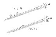
- FIG. 5Ais an isometric view from the top of a deployer on a holder, in accordance with one embodiment of the present invention.
- FIG. 5Bis an isometric view from the bottom of a deployer on a holder, in accordance with one embodiment of the present invention.
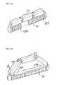
- FIG. 6is an isometric view of a holder, in accordance with one embodiment of the present invention.
- FIG. 7Ais a top view of an implant showing a locking mechanism, in accordance with one embodiment of the present invention.
- FIG. 7Bis a top view as in FIG. 7A with a tooth in a slot in locked position, in accordance with one embodiment of the present invention
- FIG. 7Cis a top view as in FIG. 7A with a tooth locked in a second locking position, in accordance with one embodiment of the present invention.
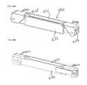
- FIG. 8is a front view of a straight beam used as a backbone for an implant and having anchoring ridges on a top and bottom surface, in accordance with one embodiment of the present invention
- FIG. 9is an end view of an implant including a backbone and a deflectable piece, in accordance with one embodiment of the present invention.
- FIG. 10is an isometric view of a segment of a deflectable piece showing a curved exterior, in accordance with one embodiment of the present invention.
- FIG. 11is a top view of a vertebra showing the vertebral body divided into four equal zones;
- FIG. 12is a top view of an implant positioned over zone two of a vertebral body by lateral access, the implant in a straightened configuration and held by a holder; in accordance with one embodiment of the present invention
- FIG. 13is a top view of the implant of FIG. 12 wherein the implant backbone is positioned over zone two of the vertebral body but the deflectable piece has been deflected into zone three by the deployer on the holder, in accordance with one embodiment of the present invention
- FIG. 14is a top view of an implant positioned on the vertebral body as in FIG. 13 , but with the holder and deployer having already been separated and removed from the implant, in accordance with one embodiment of the present invention
- FIG. 15is an isometric view of an implant with a deflected sequence of segments in the deflectable piece wherein the backbone is flat;
- FIG. 16is a flow chart showing a method in accordance with one embodiment of the present invention.
- FIG. 17is a flow chart showing a further method in accordance with one embodiment of the present invention.
- FIG. 18is a flow chart showing a still further method in accordance with one embodiment of the present invention.
- FIG. 19is a flow chart showing a further method in accordance with one embodiment of the present invention.
- FIG. 20is a flow chart showing a still further method in accordance with one embodiment of the present invention.
- FIG. 21shows isometric views of an implant and a biocompatible-material-delivery device, in accordance with one embodiment of a system of the present invention
- FIG. 22Ashows a laterally deflectable implant inserted through a TLIF approach, in accordance with one embodiment of the present invention
- FIG. 22Bshows two laterally deflectable asymmetric implants alongside one another resulting from a PLIF insertion approach, in accordance with one embodiment of the present invention
- FIGS. 23A-Bare side views of an implant, holder and deployer effectuating vertical distraction of the intervertebral space between endplates, in accordance with one embodiment of the present invention.
- FIGS. 24A-Bare top isometric views of an implant with two sequences of segments each with adjustable backbones, before and after deflection, in accordance with one embodiment of the present invention.
- FIGS. 24C-Eare top isometric views of an implant whose deflectable piece has two sequences of segments each deflected separately and independently using adjustable length backbones, in accordance with one embodiment of the present invention.
- FIG. 25Ais an isometric view of an implant with an adjustable length backbone in a straightened state, in accordance with one embodiment of the present invention.
- FIG. 25Bis an isometric view of an implant with an adjustable length backbone after deflection, in accordance with one embodiment of the present invention.
- FIG. 26Ais an isometric view of an implant whose undeflected deflectable piece includes side panels useful for vertical distraction, in accordance with one embodiment of the present invention
- FIG. 26Bis a vertical sectional view of the implant of FIG. 26A , in accordance with one embodiment of the present invention.
- FIG. 26Cis an isometric view of the implant of FIG. 26A after deflection of the deflectable piece, in accordance with one embodiment of the present invention.
- FIG. 26Dis a vertical sectional view of the implant as shown in FIG. 26C , in accordance with embodiment of the present invention.
- FIG. 27Ais an isometric view of an implant, deployment tube and holder shaft, in a straight configuration before deflection, in accordance with one embodiment of the present invention
- FIG. 27Bis an isometric view of the implant, deployment tube and holder shaft of FIG. 27A after deflection, in accordance with one embodiment of the present invention
- FIG. 27Cis an isometric view of the implant, detachment tube and holder shaft of FIG. 27A shown from an opposite side and before deflection, in accordance with one embodiment of the present invention
- FIG. 27Dis an isometric view of the implant, deployment tube and holder shaft of FIG. 27C after deflection, in accordance with one embodiment of the present invention
- FIG. 27Eis a vertical sectional view of the implant, deployment tube and holder shaft of FIG. 27C with the implant in straightened configuration, in accordance with one embodiment of the present invention
- FIG. 27Fis a vertical sectional view of the implant, deployment tube and holder shaft of FIG. 27C with the implant in partially deflected state, in accordance with one embodiment of the present invention
- FIG. 27Gis a vertical sectional view of the implant, deployment tube and holder shaft of FIG. 27C with the implant in partially deflected state, in accordance with one embodiment of the present invention
- FIG. 27His a vertical sectional view similar to FIG. 27G except with the deployment tube detached, in accordance with one embodiment of the present invention.
- FIG. 27Iis a vertical sectional view similar to FIG. 27G except with the deployment tube detached and the holder shaft also removed, in accordance with one embodiment of the present invention
- FIG. 27Jis an isometric view of the deflected implant without the deployment tube or holder shaft and revealing the engagement teeth at the rear of the threaded tube;
- FIG. 27Kis an isometric view of the end of a disconnected deployment tube showing its engagement teeth, in accordance with one embodiment of the present invention.
- the present inventiongenerally provides a method and apparatus for laterally deflectable implants, and systems and methods for implanting deflectable implants having a loop structure in a human or animal body which may be asymmetric, for example D-shaped, in a deflected state.
- the implantmay during its delivery assume a straightened or low-curvature configuration to facilitate delivery via a minimally invasive procedure.
- the implantmay have a deflectable piece having a distal end and a proximal end and may have a backbone configured to meet (i.e. to abut or interconnect with) the distal end or the proximal end.
- the deflectable piecemay be comprised of a sequence of two or more segments that may be interconnected to one another by effective hinges.
- the effective hingesmay be integral hinges such as lateral cut-outs that close upon deflection or the effective hinges may be actual mechanical hinges between the segments.
- the deflectable piecemay be interconnected with the backbone at the distal end and/or at the proximal end of the deflectable piece. If the deflectable piece is connected to the backbone at the distal end of the deflectable piece prior to deflection, then upon deflection, the deflectable piece may also be interconnected with said backbone at the proximal end of the deflectable piece. In a deflected state, for example a fully deflected state, the deflectable piece may define, together with said backbone, an asymmetric loop that defines an at least partially enclosed volume.
- either longitudinal pressuremay be applied to the proximal end of the deflectable piece or to the backbone so as to generate relative longitudinal movement between the proximal end and at least a distal end of the backbone. This may generate an outward horizontal movement of at least a central portion of the deflectable piece away from the backbone.
- the implantmay be asymmetric about an axis defined by the direction of insertion and running from the proximal and distal ends and situated between the backbone and the deflectable piece.
- the implantis arranged to open towards one side of the axis defined by the direction of insertion, and may be asymmetrical about that axis, as will be exemplified below.
- loopis used to refer to any structure in which following along the contiguous structure can lead back to the starting point while encircling at least one point lying outside the device, except that there may be a gap between a proximal end (or a distal end) of the deflectable piece and the backbone, most often the proximal end (or the distal end) of the backbone. Typically, and in one preferred embodiment, any such gap does not exceed 10% of a length of the backbone (in the case of telescoping backbones, the length of the backbone when the implant is fully deflected).
- the loopis called a modified loop or asymmetric modified loop and, if there is a gap between a proximal end (or a distal end) of the deflectable piece and the backbone, any such gap does not exceed 15% or 20% or 25% or 50% or 75% of such length, depending upon the embodiment.
- a modified loopmay be used in conjunction with any other compatible feature or step of the present invention.
- completion of the loopmay be in the form of a sliding joint.
- the word “loop”does not carry any implication of a circular or smooth shape, although such shapes are in certain cases preferred implementations of the loop structure when open.
- the word “strict loop”is used to refer to any structure in which following along the contiguous structure can lead back to the starting point while encircling at least one point lying outside the device.
- embodiments featuring strict loopsmay be used in conjunction with any other compatible feature or step of the present invention
- low curvature insertion staterefers to a configuration of the deflectable piece of the implant in which at least one dimension of the deflectable piece, for example the width, other than the longitudinal dimension (i.e. the direction of elongation) of the implant, is significantly reduced, typically to less than 50% (and in some other preferred embodiments to less than 30% or in other preferred embodiments to less than 10%) of the corresponding dimension in its fully deflected state, in order to facilitate delivery through a small orifice. Note that a “straightened configuration” would not be reduced to 0% of the corresponding dimension due to the inherent width of the deflectable piece, even when not deflected at all.
- the implantwhich may comprise the deflectable piece and the backbone together, has a “low-profile” configuration in which preferably two transverse dimensions are small compared to the direction of elongation of the implant, for easy delivery in a minimally invasive procedure, and the implant device opens up in one or two transverse dimensions when deployed.
- intervertebral implantsfor supplementing, supporting or replacing an intervertebral disc as part of a fusion procedure or as a motion preserving implant
- intravertebral implantsfor supporting or restoring a vertebral body.
- the deflectable implantsmay include a sequence of segments interconnected with effective hinges (such as conventional hinges or integral hinges) or may be formed with at least an elongated side without clearly distinguished segments.
- the deflectable piecemay comprise a sequence of segments. While a “sequence” means at least two segments, more preferably the sequence includes at least three, and in many preferred cases four or more segments.
- the segmentsmay be interconnected at effective hinges, the sequence assuming a straightened or low curvature insertion state for insertion into the body, and being deflectable to a deflected state, for example a fully deflected state, that may be defined by abutment of abutment features of adjacent of the segments.
- an implant for interbody fusionmay be deflectable to a deflected loop, for example a fully deflected loop, inside the body, where the loop defines an enclosed volume (or an at least partially enclosed volume, for example if the loop is not a strict loop and has a gap) with the upper and lower surfaces of the body.
- the implant for interbody fusionfurther includes at least one opening in one or both of the elongated sides allowing access to the enclosed volume wherein the at least one opening is used to fill the enclosed volume in the fully deflected loop state with biocompatible filling materials for interbody fusion.
- an implant for motion preservationis disclosed.
- the implantis deflectable to a deflected loop, for example a fully deflected loop, inside the body, where the loop defines an enclosed volume (or an at least partially enclosed volume, for example if the loop is not a strict loop and has a gap) with the upper and lower surfaces of the body.
- the implant for interbody fusionfurther includes at least one opening in one or both of the elongated sides allowing access to the enclosed volume wherein the at least one opening is used to fill the enclosed volume in the fully deflected loop state with inert biocompatible filling materials applicable for motion preservation.
- an implant system for implanting implants described herein aboveincludes further an injector containing filling materials such as but not limited to biocompatible materials, bone grafts, bone chips, bone-growth enhancing agents for interbody fusion or inert filling materials, such as cement for interbody fusion or for stabilizing compression fractures, or other nucleus reinforcement or replacement material for motion preservation.
- filling materialssuch as but not limited to biocompatible materials, bone grafts, bone chips, bone-growth enhancing agents for interbody fusion or inert filling materials, such as cement for interbody fusion or for stabilizing compression fractures, or other nucleus reinforcement or replacement material for motion preservation.
- the present implantmay be asymmetric, such as D-shaped and may, in a deflected state, comprise an asymmetric loop that may define an at least partially enclosed volume.
- the implant of the present inventionmay be comprised of (i) a deflectable piece and (ii) a backbone that is not deflectable or at least not normally deflected.
- the deflectable piecemay be comprised of a sequence of segments that may be interconnected at effective hinges.
- the effective hingesmay be lateral cut-outs, for example triangular lateral cut-outs that may close upon deflection.
- the deflected statefor example the fully deflected state, may be defined by abutment of abutment features (for example surfaces, which may also be called abutment surfaces) of adjacent segments of the sequence.
- abutment featuresfor example surfaces, which may also be called abutment surfaces
- the implant of the present implantmay open upon longitudinal pressure applied either to a proximal end of the deflectable piece or to the backbone to generate relative longitudinal movement between at least a distal end of the backbone and the proximal end of the deflectable piece.
- this application of longitudinal pressuremay generate relative longitudinal movement between the proximal end of the deflectable piece and at least a distal end of the backbone and may generate an outward horizontal movement (transverse to the longitudinal movement and in a preferred embodiment along a plane of or substantially parallel to an intervertebral disc) of at least a central portion of the deflectable piece away from the backbone, thereby deflecting the deflectable piece to the deflected state to form, with said backbone, an asymmetric loop, such as a D-shaped loop.
- the implant of the present inventionmay have a deflectable piece that is free on its proximal end prior to insertion and prior to and during at least a portion of its deflection but meeting (abutting or interconnected to) the backbone at a distal end after the deflection, or at least during the deflection.
- the implant of the present inventionmay be asymmetric along an axis defined by a direction of insertion and running between a proximal and distal end of the deflectable piece and situated between the backbone and deflectable piece. Accordingly, the implant of the present invention may expand asymmetrically by deflection of the deflectable piece on only one side of the axis.
- the height of the backbonemay in certain preferred embodiments be at least as great as the deflectable piece (or, in other preferred embodiments, at least as great as a proximal segment of the deflectable piece).
- At least one segmentmay have a curved exterior and/or may have an elliptical and/or anatomically shaped cross-section, at least at a top, bottom and at least one side (i.e. the at least one segment has a cross-section that corresponds to an ellipse at a top, a bottom and at least one side of the at least one segment).
- the method of implanting of the present inventionmay involve inserting the implant laterally, which has clinical benefits, such as avoiding the nerve root, avoiding major blood vessels, eliminating the need for a facetectomy, and allowing very large implants to be implanted to afford greater stability.
- the method of implanting of the present inventionin certain preferred embodiments may involve initially inserting the implant into an anterior portion of a spine and then deployed posteriorly.
- the implantmay be laterally inserted into zone two of the spinal column and then deflected into zone three and/or zone four.
- the method of the present inventionmay involve inserting posteriorly and then deflecting anteriorly.
- the method of the present inventionmay involve setting an initial position of the backbone so as to pre-define the final position of the implant.
- the backbonemay be held stationary during deflection of the deflectable piece.
- the backbonemay be configured to hold at least a majority of the load of the implant and may be configured to be emplaced under or between cortical bone to receive the impact of such load.
- the backbonemay be a solid beam whose width may be at least half the height of the backbone (or in other preferred embodiments, at least two-thirds or at least three-quarters or in some preferred embodiments between one times the height and one and a half times the height or in other preferred embodiments between one half times and one and one half times the height).
- one method of the present inventionmay involve inserting two laterally deflectable implants so that their backbones may be substantially parallel and may be alongside one another and then deflecting each of the implants in opposite lateral directions to define two asymmetric loops.
- one embodiment of the present inventionis a method of implantation involving inserting the implant in a straightened or low curvature state and deflecting vertically to distract an intervertebral space between two discs of a spine.
- one embodiment of the present inventionmay involve separately deflecting different sequences of interconnected segments of the deflectable piece of the implant, wherein the different sequences combines comprise the deflectable piece.
- One application of thisis to deflect the implant so as to form a “B” shaped implant.
- the implant of the present inventionmay utilize a backbone that telescopes to adjust its length and thereby generate the relative longitudinal movement between the proximal end of the deflectable piece and at least a distal end of the backbone.
- a laterally deflectable implantmay be in a straightened or low curvature insertion state for insertion into the body.
- the implant 10is in a straightened insertion state.
- Implant 10may comprise a deflectable piece 20 that may have a distal end 22 and a proximal end 24 and a backbone 30 that may be configured to meet (i.e. abut or interconnect with) deflectable piece 20 , for example at the distal end 22 of deflectable piece 20 (or at the proximal end 24 ).
- a deflectable piece 20may be formed of a single body of flexible material and may have at least a first and a second elongated side.
- Backbone 30is typically generally straight and normally is not configured to deflect.
- Backbone 30may abut or interconnect with deflectable piece at a distal end 36 of backbone 30 (or at a different portion of backbone 30 ). Typically this positioning may be such that deflectable piece 20 is interconnected with backbone 30 or else deflectable piece 20 may merely abut backbone 30 . If the backbone and deflectable piece are abutting without an interconnection, this may still allow application of longitudinal pressure against deflectable piece 20 or backbone 30 to cause relative longitudinal movement of proximal end 24 relative to at least a distal end 36 of backbone 30 causing deflection of deflectable piece 20 . “Distal end” of backbone 30 is defined to mean the last 10% of backbone 30 .
- the relative longitudinal movement of proximal end 24is relative to at least a “distal part” of the backbone, which may be the last 5%, or in other preferred embodiments the last 15%, or the last quarter, or the last third, or the last 40%, or in still other preferred embodiments the region of attachment of the distal segment to the backbone.
- the proximal end 24 of deflectable piece 20moves longitudinally relative to the entire backbone 30 (particularly when the backbone is not an adjustable length backbone).
- deflectable piece 20 and backbone 30are interconnected even before insertion of the implant 10 into the body.
- backbone 30may be inserted into the body first and then deflectable piece 20 may be inserted so as to interconnect along a rail on backbone 30 , for example sliding along the rail longitudinally until deflectable piece 20 abuts a tip 37 of backbone 30 .
- Deflectable piece 20may be hingedly interconnected with backbone 30 at distal end 22 of the deflectable piece, as shown in FIG. 2 . Note that when deflectable piece 30 is in a straightened (or low curvature) configuration, implant 10 is said to also be in a straightened (or low curvature) configuration.
- backbone 30When deflectable piece 20 is in its straightened or low curvature configuration, backbone 30 may extend alongside deflectable piece 20 , as shown in FIG. 1 . When deflectable piece 20 is in its deflected state, backbone 30 may be alongside only the ends 22 , 24 of deflectable piece 20 and backbone 30 may extend from the distal end 22 of the deflectable piece 20 to the proximal end 24 thereof.
- deflectable piece 20 in a deflected statemay also be interconnected (for example hingedly) with said backbone 30 at the proximal end 24 of deflectable piece 20 and backbone 30 may then extend between the distal end 22 and the point of interconnection which may be proximal end 24 of the deflectable piece 20 .
- the proximal end 24 of deflectable piece 20is not in contact with the backbone prior to deflection of the deflectable piece 20 .
- the deflectable piece 20When deflected, for example when fully deflected, the deflectable piece 20 may define, together with backbone 30 , an asymmetric loop 39 (or asymmetric modified loop), which may be D-shaped. D-shaped loop 39 may define an at least partially enclosed volume 39 V.
- the asymmetric loopWhen the deflectable piece 20 of implant 10 is fully deflected, the asymmetric loop may in some embodiments have a toroidal shape, for example a ring toroid or an oval toroid (or in other embodiments a toroidal polyhedron).
- the interconnection between proximal end 24 of deflectable piece 20 and backbone 30may typically occur at or near the completion of the deflection, although this is not a requirement or a limitation of implant 10 .
- asymmetric loop 39may not be fully closed—for example even in a fully deflected state there may be a gap between backbone 30 and the proximal end 24 of deflectable piece 20 .
- any such gapdoes not exceed 10% of a length of the backbone (in the case of telescoping backbones, the length of the backbone when the implant is fully deflected) and in other preferred embodiments, does not exceed 15% or 20% or 25% of such length.
- deflectable piece 20may comprise a sequence 41 of segments 40 , for example segments 40 a , 40 b and 40 c .
- Segments 40is used to refer in general to the segments 40 a , 40 b , 40 c , etc.
- Segments 40may be interconnected with one another at effective hinges 47 for example effective hinges 47 a , 47 b , etc.
- the effective hinges 47may be comprised of lateral cut-outs 48 a , 48 b , 48 c between segments 40 a , 40 b , 40 c and 40 d .
- the lateral cut-outs 48 a - cmay be triangular or substantially triangular and as shown in FIG. 4 may close upon deflection.
- the sequence 41 of segments 40is deflectable to a deflected state, for example a fully deflected state, defined at least partially by abutment of abutment features 43 (for example surfaces) of adjacent segments of the sequence 41 of segments 40 .
- the abutment features 43may function as a limiter feature to prevent rotation about the hinges beyond the desirable range in either clockwise or counterclockwise direction(s).
- another limiting featuremay be used, for example a limiter built-in to the hinge (not shown).
- the segments 40may be interconnected to one another by interdigitation, for example interlocking fingers.
- proximal end 24 of deflectable piece 20is a part of the most proximal segment 40 a .
- middle segment 40 bmay have a side surface 25 .
- longitudinal pressuremay be applied to the proximal end 24 of the deflectable piece 20 .
- thismay be accomplished with a deployer or “pusher” component 60 which may be a separate component or may be located on a holder 50 ( FIG. 6 ).
- Application of the longitudinal pressuremay generate relative longitudinal movement between the proximal end 24 and backbone 30 to cause deflection of deflectable piece 20 .
- the longitudinal pressuremay generate an outward horizontal (lateral) movement (transverse to the longitudinal movement and, in a preferred embodiment, along a plane of or substantially parallel to an intervertebral disc) of at least a portion 28 of the deflectable piece 20 away from the backbone 30 , thereby deflecting the deflectable piece 20 to the deflected state to form the asymmetric loop 39 together with backbone 30 .
- the portion 28 referred tomay be a central portion of deflectable piece 20 , which in this context is not in any way limited to a portion that is right in the middle of deflectable piece 20 or necessarily in a middle segment 40 of the deflectable piece 20 . Rather, the central portion is any portion that is not at the very remote end at the distal end 22 and not at the very remote end at the proximal end 24 of deflectable piece 20 .
- the central portion 28may be thought of as a bow expanding outward with the ends fixed.
- the outward expansioni.e. the deflection of the deflectable piece 20
- the deflection of deflectable piece 20may be centered at a point that is not at the midpoint between the distal and proximal ends 22 , 24 .
- the deflection of deflectable piece 20allows the deflectable piece together with the backbone to form a loop, and in particular a D-shaped loop.
- proximal end 24instead of longitudinal pressure applied against proximal end 24 , for example to push proximal end 24 , there may be longitudinal pressure applied to backbone 30 , for example to pull a distal end 32 of backbone 30 .
- backbone 30may be generated to deflect deflectable piece 20 to its deflected state and thereby form asymmetric loop 39 .
- backbone 30may be adjustable in length. Accordingly, in embodiments in which the length of backbone 30 is adjustable and this adjustability is utilized to generate relative longitudinal movement between a proximal end of deflectable piece 20 and at least a distal end of the backbone, the proximal end 24 of deflectable piece 20 may be in contact with backbone 30 (and in fact may be attached to backbone 30 ) even before deflection of deflectable piece 20 .
- backbone 30may include a first telescoping portion 88 a of the backbone 30 that telescopes into or with a second telescoping portion 88 b of backbone 30 . As seen in FIG.
- the proximal end 24 of deflectable piece 20may be attached to first telescoping portion 88 a of the backbone such that deflection of the deflectable piece 20 is actuated by moving the first telescoping portion 88 a relative to the second telescoping portion 88 b of backbone 30 .
- first and second telescoping portions 88 a , 88 bmay be linearly aligned (i.e. collinear) as part of backbone 30 .
- first and second telescoping portions 88 a , 88 bwhen they telescope within one another, they do so without one telescoping portion sticking out the other longitudinal end of the other telescoping portion.
- first and second telescoping portionsmaintain substantially equal heights even when telescoping within one another (since for example the outer surfaces of each may not participate in the telescoping).
- the deflectable piece 20is comprised of a first sequence of segments associated with first and second telescoping portions 88 a , 88 b of the backbone 30 and is comprised of a second sequence 41 of segments associated with third and fourth telescoping portions 88 a , 88 b of the backbone.
- the present inventionmay utilize in any suitable embodiment of implant 10 (or method or assembly) an implant 10 having an adjustable-in-length backbone 30 in which axial movement between parts of the backbone 30 is accompanied by relative rotation of the parts.
- the backbonemay comprise a rotatable element 93 and an annular element 95 , the rotatable element attached to or abutting the deflectable piece and configured to move longitudinally by rotatingly engaging the annular element.
- Rotatable element 93may be a tube 93 such as a threaded tube 93 that is threaded at a distal portion 93 a thereof, such as at a tip 93 a .
- the annular element 95may be a threaded nut 95 , such as a female threaded nut, that receives the rotational movement of the threaded tube. Threaded nut 95 may be fixed.
- This embodimentresembles telescoping but differs from “telescoping” (which typically involves axial movement of a part within a part without accompanying rotation of these parts) since here, besides longitudinal/axial movement of a part of backbone 30 within another part, there may also be rotation of at least one part of the backbone 30 , and typically rotational engagement or relative rotation between that one part and at least one other part of the backbone 30 .
- a pin 96may be used to connect a segment 40 a (which in the view of FIG. 27A is a distal segment) of deflectable piece 20 to backbone 30 .
- a proximal axis/axle 97may be used to attach a proximal end of rotatable element 93 to deflectable piece 20 , for example to proximal segment 40 c , or in general to a proximal part of deflectable piece 20 .
- the deflectable piecemay move longitudinally relative to at least a distal end of the backbone when the rotatable piece 93 advances longitudinally with respect to annular element 95 .
- An implant assembly 1000may include an implant 10 with this kind of adjustable-in-length backbone 30 and may further include a holder shaft 92 running through the backbone 30 , the holder shaft 92 including a holder shaft tail 92 a jutting out a proximal end of the implant.
- Such an assemblymay further comprise a deployment tube 91 enclosing the holder shaft tail 92 a and being operatively engaged to the rotatable element 93 to rotate the rotatable element 93 .
- FIG. 27Eis a vertical sectional view of an implant 10 whose deflectable piece 20 comprises segments 40 a , 40 b , 40 c and whose backbone comprises a threaded tube 93 and a female threaded nut 95 .
- a usermay first insert a holder shaft 92 through implant 10 , for example through the entire length of implant 10 .
- the holder shaft 92may connect to a distal tip of implant 10 .
- the holder shaft 92may have a holder shaft tail 92 a that sticks out the proximal end of implant 10 and may attach to a handle (see FIGS. 5A-6 ).
- the usermay then attach a deployment tube 91 over holder shaft tail 92 a such that engagement teeth 91 b of the deployment tube 91 mate with engagement teeth 93 b at the proximal end of threaded tube 93 , as seen in FIGS. 27G-27K , especially FIGS. 273-27K .
- the embodiments in which the length of the backbone 30 is adjustablemay have any of the other structural features of implant 10 described herein, and may be used in any of the methods described below, although as indicated such embodiments typically would not employ a deflectable piece 20 whose proximal end 24 is not in contact with the backbone 30 of the implant prior to deflection.
- Asymmetric loop 39may assume other shapes besides a D-shape such as rectangular, trapezoidal, triangular and B-shaped (i.e. two D-shaped implants with backbones that are substantially aligned). Moreover, in certain preferred embodiments, there may be two implants lined, up such that the backbones 30 of each implant are substantially parallel or alongside one another such that the two implants together form two D-shapes. Moreover, “D-shape” does not require a perfect D. There could be a slight projection of backbone 30 beyond where backbone 30 meets deflectable piece 20 on the proximal and/or distal end.
- proximal end 24 of deflectable piece 20may be a free proximal end during insertion of the implant, i.e. not connected to backbone 30 or to another element of implant or of holder 50 or deployer 60 .
- Proximal end 24may be free proximal end during at least a majority of the deflection of the deflectable piece, the majority measured by reference to how great of an outward horizontal distance the deflectable piece 20 has moved.
- proximal end 24is attached to backbone 30 at or near the end of the application of longitudinal pressure by deployer 60 .
- proximal end 24may be free other than in the deflected state, for example the fully deflected state, of the deflectable piece 20 . In other preferred embodiments, however, proximal end 24 may be free even in the fully deflected state. In some preferred embodiments, for example as shown in FIG. 1 , the proximal end 24 of deflectable piece 20 is not in contact with backbone 30 prior to deflection of deflectable piece 20 .
- a proximal end 24 of deflectable piece 20may interconnect with the backbone at a proximal end of backbone 30 , for example at the culmination of the deflection of deflectable piece 20 .
- backbone 30is not configured to deflect and is normally rigid.
- backbone 30could for example have a slit allowing at least a portion of backbone 30 to bend, for example up to 15 or 20 rotational degrees of the longitudinal axis of backbone 30 (as measured from a distal to a proximal end of backbone 30 ), so as to facilitate engagement of a proximal end of deflectable piece 20 to backbone 30 , for example at the culmination of the deflection of deflectable piece 20 .
- backbone 30would resume its original shape after the engagement with deflectable piece 20 .
- implant 10may be asymmetric about a longitudinal axis running from one end of deflectable piece 20 to the other (for example in a direction of insertion of the implant 10 ) when the implant 10 is in a deflected state.
- the asymmetrymay be particularly pronounced for example when the longitudinal axis is situated between the deflectable piece 20 and the backbone 30 , for example where the backbone, deflectable piece and longitudinal axis are all on substantially one plane.
- the implant (and the loop) in a deflected statemay be asymmetric such that the implant (and the loop) does not have an axis of symmetry parallel to the backbone 30 .
- the implant 10including the backbone 30 and deflectable piece 20 , may be made of any suitable biocompatible material (i.e. titanium, PEEK, shape memory alloy, steel, cobalt-chrome alloy etc.).
- the cross-section of implant 10may be straight, as shown in FIGS. 1-2 , or may be angled to create a lordotic angle between the vertebral bodies.
- the lordotic anglemay be created by having segments (of deflectable piece 20 ) of varying or graduated heights within the same implant 10 .
- An end 32 ( FIG. 2 ) of backbone 30may interface with a holder instrument 50 (see FIG. 6 and FIG. 12 ) that holds implant 10 .
- holder 50may be an elongated instrument and may be made of metals, polymers or a combination of materials.
- One end 52 (i.e. a distal end) of holder 50may have one or more such interfaces with functions such as anti-rotation of implant device 10 on the instrument 50 , quick connect/quick release or other attachment/release method of the implant 10 .
- the anti-rotation feature 32 a on the proximal end 32 of backbone 32may interface with an anti-rotation feature on the distal end of holder 50 .
- the interface featuresmay appear on corresponding ends of the holder 50 and backbone 30 .
- the proximal end 54 of holder 50may have a surface for pushing or tapping to effectuate advancing the implant 10 into the desired location in the body.
- the interface on distal end 52may be connected to a component(s) 66 (i.e. a knob, button, dial, handle, etc.) on the proximal end 54 so that the user can perform the necessary functions to the implant 10 (connect, deploy, disconnect, etc.).
- deployer 60may have a component for aligning or directing a biocompatible material such as bone into the window 29 of deflectable piece 20 or of a segment(s) of the sequence 41 of segments 40 .
- Deployer 60may be integrally formed as part of the holder 50 and located on holder 50 or may be a separate instrument, or in a third possibility, deployer 60 may be attached to holder 50 intraoperatively.
- Deployer 60may have a distal end 62 that interfaces with a proximal portion of deflectable piece 20 , in particular in certain preferred embodiments with a segment of implant 10 , most likely proximal end 24 forming part of proximal segment 40 a of implant 10 .
- deployer 60When the deployer 60 is advanced longitudinally, deployer 60 pushes or moves the proximal end 24 , this causes deflection of the deflectable piece 20 to the deflected state.
- deployer 60may be advanced axially by squeezing or pushing handles 66 located on the holder and deployer 60 .
- the handlesmay be fixed on the holder 50 and deployer 60 or may be removable.
- the handle 66may have a spring component (not shown) to return the handles 66 to their original position after squeezing/pushing them to advance the deployer 60 .
- 5A-6may be utilized with any suitable implant or method or assembly or system described in this patent application, although for embodiments in which the backbone 30 is telescoping, the deployer 60 would more typically interact directly with backbone 30 rather than directly with deflectable piece 20 (although even in this telescoping backbone embodiment a deployer 60 could instead interact directly with deflectable piece 20 ).
- the adjustable in length backbone embodiment shown in FIGS. 27A-Kmay utilize its own suitable holder shaft 92 and deployment tube 91 , as described therein, and the deployment tube 91 used for this embodiment may interact directly with the backbone or backbone element (i.e. threaded tube 93 ), as described.
- the implant 10 in its final positionmay protrude beyond the vertebrae on the ipsi (proximal to the holder/deployer) and/or contra lateral side.
- backbone 30may be at least as great as the maximum height of the deflectable piece 20 .
- backbone 30may be elongated.
- Backbone 30may be a beam, such as a solid beam or a beam that is mostly solid, or solid except for particular openings. “Solid” does not preclude being solid with openings.
- a “beam”is defined to have two dimensions other than its length such that an average size of one of those two dimensions is at least 30% of an average size of the second of those two dimensions of the beam.
- a straight beam used as backbone 30may have anchoring ridges 38 on a top surface 31 and on a bottom surface 34 . This beam may be used in motion preservation implants of the present invention.
- the top 31 of the beam 30i.e. the backbone 30
- the top 31 of the beam 30may be configured to engage cortical bone in the body and receive an impact from a load of the cortical bone.
- Deflectable piece 20may have a height, a width and a length.
- the length of deflectable piece 20may be along a direction of insertion of the implant and may be by far the largest dimension.
- backbone 30may be configured such that the width of the backbone (the dimension transverse to the height and transverse to the length) is at least half as large as a height of the backbone, or in other preferred embodiments at least three-quarters as large as the height, or between one half and one and a half the height in other preferred embodiments.
- the “height” of the backbone 30is defined to mean the dimension perpendicular to the plane in which the implant 10 device opens.
- the “width” of the backbone 30is the dimension transverse to the elongated length of the implant (and is parallel to the axis referenced herein that runs from the proximal and distal ends of the deflectable piece and is situated between the backbone and the deflectable piece).
- the width of backbone 30allows it to withstand a load.
- backbone 30may be hollow, solid or partially hollow, in preferred embodiments, backbone 30 may be configured to hold at least a majority (or in some other preferred embodiments at least two-thirds or at least three-quarters) of a load held by the implant 10 .
- Implant 10may be placed under cortical bone (for example the bone of a spinal disc adjacent a vertebral body) and the top surface 31 of the beam may be configured to engage cortical bone in the body and receive an impact from a load of the cortical bone. Implant 10 may be anatomically shaped to similarly match the contour of the vertebral endplate.
- the brunt of the necessary impact to cross the annulus to the contralateral sidemay be carried by the straight beam.
- the beam 30may take its seat on the annular ring after proper sizing is performed. Stability of the implant relies on the initial small aperture in the annulus to allow passage of the implant—and then the gradual sinking of the ridges 38 along the beam 30 into the surrounding tissues.
- the beamis the most anteriorly located part of the implant 10 , mechanically supporting the lordosing effect. Accordingly, the height of the beam may be greater than the height of the deflectable piece.
- backbone 30may have a window 33 or an opening to allow biocompatible material (such bone graft) to pass into the anterior area of the vertebral body, i.e. zone one.
- Backbone 30may also have a contoured tip 37 ( FIG. 1 ), for example in the form of a bullet nose, to ease insertion of the implant device 10 in between hard tissue (i.e. two adjacent vertebral bodies).
- Backbone 30may also have ridges 38 , as shown in FIGS. 3-4 on a surface (for example top surface 31 or a bottom surface or side surface) that comes into contact with the tissue of the body in order to prevent movement in an undesired direction.
- Ridges 38may be in the form of teeth, pyramids, knurls or similar structures. Ridges 38 may be perpendicular to a length of the backbone, as shown in FIGS. 3-4 , or the ridges 38 may be parallel to such length, at an angle, in a combination of directions, and may be on all or only part of the surface. Furthermore, the ridges 38 may vary in height or may be of the same height, and ridges 38 may be straight or curved.
- the opening 29is in a proximal segment 40 a or in another segment 40 . In other embodiments, opening 29 can be between adjacent segments 40 .
- Proximal segment 40 amay have an interface with pusher component 60 ( FIGS. 5A-5B ) which allows the segments 40 to be pushed and advanced from the straight configuration to the deflected or fully deflected state.
- deflectable piece 20which may be comprised of the sequence 41 of segments 40 , is resiliently biased towards the fully deflected state, and is temporarily deformed to the insertion state.
- a guidemay maintain deflectable piece 20 straight during insertion and removal of the guide then permits deflection of the deflectable piece 20 , for example by deflection of segments 40 , to an original shape. In this sense, the deflectable piece 20 exhibits elastic memory.
- a hollow 45i.e. a cavity 45
- axial loadingmeans loading in the height direction (i.e. perpendicular to the plane in which the implant 10 opens).
- Backbone 30may also have a hollow cut-out 35 , as shown in FIG. 9 .
- at least one segment of the sequencemay also have a lateral cut-out 44 extending to the hollow 45 .
- At least one segment 40may have a curved exterior. As shown in FIGS. 9-10 , the at least one segment may have an elliptical cross-section at a top, a bottom and at least one side of the at least one segment, that is the at least one segment may have a cross-section that corresponds to an ellipse at a top, a bottom and at least one side of the at least one segment. This may be useful for flexibility for axial loading in the case of motion preservation implants.
- the hollow cut-out, lateral cut-out, curved exterior and other structural features shown in FIGS. 8-10may be applied to the deflectable piece 20 (segmented or non-segmented) and backbone 20 (whether or not adjustable in length) of any suitable implant, method step, assembly or system described in this patent application.
- the deflectable piece 20may be a flexible non-segmented piece, as described herein.
- the present inventionmay also be described as an implant system comprising the implant 10 and further comprising an elongated conduit for inserting said implant in said straightened insertion state into the body.
- the present inventionmay also be described as a system 94 comprising the implant 10 and further comprising a delivery device such as an injector 83 containing filling material selected from the group consisting of: biocompatible materials, bone grafts, bone chips, bone-growth enhancing agents for interbody fusion, cement and filling materials for motion preservation.
- injector 83may include a body 83 A, a plunger 83 B and a cartridge 83 C.
- injectormay also include a tip 83 D that passes through body 83 A and cartridge 83 C.
- Cartridge 83 Cmay be a tube with one end to fit the window 29 of implant 10 and the other end to attach to the remainder of device 83 .
- Plunger 83 Bmay interface or connect with implant holder 50 ( FIG. 6 and FIG. 12 ) and other delivery instruments. After the cartridge 83 C is filled with the biocompatible material such as bone graft, cartridge 83 C may be attached to the body 83 A of delivery device 83 at a time when the plunger 83 B is in the “back” position.
- the deviceis then positioned so that the distal tip of the cartridge 83 C is placed at the delivery window 29 of implant 10 .
- the plunger 83 Bis then advanced so that it pushes the biocompatible material through cartridge 83 C and into the implant 10 .
- the device 83may then be removed. If additional biocompatible material is needed, such material may be inserted into cartridge 83 C and the remaining steps repeated as necessary.
- implant 10may also comprise a locking arrangement to retain said implant in the pre-defined deflected state or range and/or to prevent undesired motion between backbone 30 and deflectable piece 20 (or at least one segment 40 of deflectable piece 20 ).
- the locking arrangementmay include at least one element selected from: cords, cables, strips, hooks, ratchets, interconnections and snaps.
- Locking mechanism 70may be on segments 40 .
- backbone 30has slots 76 A, 76 B or other female elements into which a one or more teeth 75 ( FIG. 7B ) mate. Teeth 75 may project from a segment 40 , for example on an internal side of segment 40 .
- FIG. 7Abackbone 30 has slots 76 A, 76 B or other female elements into which a one or more teeth 75 ( FIG. 7B ) mate.
- Teeth 75may project from a segment 40 , for example on an internal side of segment 40 .
- FIG. 7Abackbone 30 has slots 76 A, 76 B
- FIGS. 7A-7Cdepicts teeth 75 positioned in an optional second locking position by mating with a second slot 76 b on backbone 30 .
- the locking mechanism 70 illustrated in FIGS. 7A-7Chas been described in the context of the specific implant shown in these figures, it should be emphasized that, as with other structural features described herein, this locking mechanism 70 or another locking arrangement described herein may be utilized on any suitable implant or assembly or system or method step outlined in this patent application.
- deflectable piece 20may deflect by deforming reversibly.
- implant 10 amay utilize a backbone 30 a that may comprise a flat and relatively thin segment that may be hingedly interconnected with the sequence of segments of the deflectable piece 30 at a distal end of said sequence.
- the sequence 41 of segmentsmay be configured to slidingly interconnect with said flat segment 30 a at a proximal end 41 a of the sequence of segments 40 .
- FIG. 15shows the deflectable piece 20 after longitudinal pressure has been applied to generate a sliding longitudinal movement of the sequence 41 relative to the backbone 30 a.
- the present inventionmay be described as a method 100 of implanting an implant 10 into a body.
- Method 100may have a step 110 of inserting the implant into an anterior portion of the body using lateral access while the implant is in a straightened or low curvature state, as shown in FIG. 12 .
- the implantmay have a backbone 30 and a deflectable piece 20 meeting (i.e. interconnected to or abutting) the backbone at a distal end 22 of the deflectable piece.
- the backbone 30may be positioned, in a preferred embodiment, on the vertebral lips (apophyseal ring) or within the confines of the annulus.
- the deflectable piece 20 used in this method (and other methods)may be comprised of a sequence of segments 40 and in general may be structured as described above for implant 10 .
- Method 100may also have a step 120 of deploying the implant, for example posteriorly, by deflecting the deflectable piece, as shown in FIG. 13 .
- step 110may involve inserting the implant onto zone two of the intervertebral disc and step 120 may involve deploying the deflectable piece posteriorly onto zone three and/or zone four of the intervertebral disc.
- the deflecting of deflectable piece 20may deflect implant 10 into an asymmetric, for example D-shaped, loop by applying longitudinal pressure to the proximal end of the deflectable piece or by applying longitudinal pressure to the backbone 30 to pull the backbone. In either case, this may generate relative longitudinal movement between the proximal end and at least a distal end of the backbone and may generate an outward horizontal movement of at least a portion (for example a central portion) of the deflectable piece away from the backbone. As shown in FIGS. 12-13 , this deflection may be accomplished without a tensioning element and without a mechanical linkage. For example, as shown in FIG.
- the application of longitudinal pressuremay be achieved by using a pusher/deployer to apply longitudinal pressure to a proximal end (which may be a proximal segment) of the deflectable piece after insertion.
- Deflecting the deflectable piece by applying longitudinal pressure to a proximal end of the deflectable piece or to a proximal end of the backbone (for example in an opposite direction for example by pulling the backbone)may generate relative longitudinal movement between the proximal end of the deflectable piece 20 and at least a distal end of the backbone and move at least a portion of the deflectable piece away from the backbone.
- deflectable piece 20is made up of segments 40 with cut-outs
- deflecting the implant into an asymmetric loopsuch as a D-shaped loop
- by applying the longitudinal pressure to the proximal end 24 of deflectable piece 20 (or to the backbone in an opposite direction) to generate relative longitudinal movement between the backbone and the proximal end 24may close or partially close cut-outs between segments of a sequence of segments of the deflectable piece, as shown in FIGS. 3-4 .
- the usermay be able to pre-define a final position of the implant in a deflected state.
- the holder and deployermay be separated and removed from the implant in a separate step.
- the implant devicewould then remain between the vertebral body shown in the FIGS. 11-13 and the one above it (not shown).
- Method 200may involve a step 210 of inserting the implant into the body while the implant is in a straightened or low curvature state, the implant having a backbone and a deflectable piece, wherein the backbone comprises a beam.
- Method 200may also have a step 220 of anchoring the implant by situating the backbone 30 on a cortical bone so that the backbone holds at least a majority of a load of the implant, or in other preferred embodiments at least two-thirds of the load.
- method 200may also involve configuring the backbone so that a height of the backbone is at least a maximum height of the deflectable piece.
- method 200may involve configuring the backbone so that a width of the backbone is at least half as large as a height of the backbone, or configuring the backbone so that a width of the backbone is at least three-quarters as large as a height of the backbone, or configuring the backbone as a solid beam (or a solid beam with openings appropriate for delivery of biocompatible material or instruments).
- Method 200(or any of the other methods herein) may also involve a further step of inserting a biocompatible material into the at least partially enclosed volume through a window in the implant.
- Step 230may involve guiding the deflectable piece by causing relative longitudinal movement between a proximal end of the deflectable piece and the backbone either by holding the backbone stationary while applying longitudinal pressure to a proximal end of the deflectable piece or by pulling the backbone while the deflectable piece is stationary or by closing a telescoping backbone.
- Thismay deflect the deflectable piece such that the deflectable piece together with the backbone form an asymmetric loop, for example a D-shaped loop, the asymmetric loop defining an at least partially enclosed volume.
- Method 300may include a step 310 of inserting the implant into a portion of the body while the implant is in a straightened or low curvature state, the implant having a backbone and a deflectable piece, for example comprising a sequence of segments interconnected at effective hinges.
- a further step 320may involve having a distal end (for example a distal segment) of the sequence meet the backbone (i.e. by abutting or being interconnected to the backbone) at a distal end of the deflectable piece. This may occur prior to insertion (with the backbone or after insertion of the implant.
- a further step 330may involve deploying the implant so as to form a loop between the backbone and deflectable piece together by deflecting the deflectable piece such that a proximal end of the deflectable piece moves longitudinally relative to at least a distal end of the backbone (by either applying longitudinal pressure to the proximal end, for example while holding the backbone stationary, or by pulling the backbone for example while holding the proximal end 24 stationary or for example by closing a telescoping backbone).
- the proximal endmay also interconnect to the backbone.
- method 300may also have a step of inserting the implant onto an intervertebral disc using lateral access to the disc and then deploying the implant posteriorly if the implant was inserted onto an anterior portion of the disc and anteriorly if the implant was inserted onto the posterior portion of the disc. It should be fully understood, however, that in other preferred embodiments, an approach other than lateral access may be used to insert the implant into the body.
- Method 300may also have a step of locking the implant to prevent undesired motion of the deflectable piece relative to the backbone.
- Another step of method 300may be applying longitudinal pressure to a proximal segment of a sequence of segments comprising the deflectable piece so as to deflect the deflectable piece such that the deflectable piece together with the backbone form an asymmetric loop such as D-shaped loop, the asymmetric loop defining an at least partially enclosed volume.
- Method 300may involve a step of configuring the backbone so that a width of the backbone is at least half as large as a height of the backbone, or in other preferred embodiments at least two-thirds as large, at least three-quarters as large, at least equal to, or between half and one and a half the height.
- Method 300may also involve deploying the implant while the backbone is maintained stationary along an axis defined by a direction of insertion.
- Method 400may have a step 410 of inserting into the body a first laterally deflectable implant that has a first backbone and a first deflectable piece while the first deflectable piece is in a straightened or low curvature insertion state.
- a further step 420may be inserting into the body a second laterally deflectable implant that has a second backbone and a second deflectable piece while the second deflectable piece is in a straightened or low curvature insertion state and such that the first and second backbones are between the first and second deflectable pieces.
- the second laterally deflectable implantis inserted into the body such that the first backbone and the second backbone are substantially parallel.
- “Substantially parallel”is defined to mean parallel or within 20 rotational degrees of being perfectly parallel.
- the first and second backbonesare within five rotational degrees (or ten rotational degrees or fifteen rotational degrees in other preferred embodiments) of being perfectly parallel.
- the inserting of the first and second laterally deflectable implants in the bodymay be implemented so that the first and second backbones are between the first and second deflectable pieces, as shown in FIG. 22 .
- Method 400may also involve a step 430 of deflecting the first and second laterally deflectable implants in opposite directions such that the first laterally deflectable implant defines a first asymmetric loop (which may be D-shaped), said first asymmetric loop defines an at least partially enclosed volume and such that the second laterally deflectable implant defines a second asymmetric loop (which may be D-shaped), said second asymmetric loop defines an at least partially enclosed volume.
- the shapes of the first and second asymmetric loopsare the same (i.e. D-shaped and D-shaped, rectangular and rectangular, etc.) although in other preferred embodiments, one can be D-shaped and the other rectangular or another asymmetric shape.
- a further step of method 400may be generating relative longitudinal movement between at least a distal end of the first backbone and a proximal end of the first deflectable piece to deflect the first deflectable piece and generating relative longitudinal movement between at least a distal end of the second backbone and a proximal end of the second deflectable piece to deflect the second deflectable piece.
- Method 400may be useful for two implants inserted in parallel fashion through a PLIF, as shown in FIG. 22B .
- Method 500may also be described as a method 500 of distracting intervertebral space 73 between discs or between a first and a second vertebrae 81 , 82 .
- Method 500may have a step 510 of inserting an implant 10 structured as described herein into a body while the implant 10 is in a straightened or low curvature state, the implant having a backbone 30 and a deflectable piece 20 meeting the backbone (interconnected or abutting).
- step 510may involve inserting an instrument assembly including an element having the structure of implant 10 (although by right it is not called an implant since it is not implanted into the body but rather inserted and removed), together with an integrally formed deployer and a holder.
- This instrument assemblywould be removed after distraction is performed and its purpose may have been merely to assess the size of a possible distraction involving an implant.
- Method 500may have a further step 520 of generating relative longitudinal movement between a proximal end of the deflectable piece and at least a distal end of the backbone so as to deflect the deflectable piece and distract an intervertebral space between the first and second vertebrae (i.e. between adjacent first and second vertebrae).
- Method 500may also have a step of inserting the implant into the body such that the backbone of the implant is abutting or facing an endplate of one vertebra (of the first and second vertebra) and the deflectable piece is abutting or facing an endplate of another vertebra (of the first and second vertebrae).
- Thismay be implemented by for example inserting the implant 10 vertically into a vertebral body that has collapsed and the using step 520 to generate relative longitudinal movement between a proximal end of the deflectable piece and at least a distal end of the backbone so as to deflect the deflectable piece and distract endplates of the same vertebra (such as to restore vertebral height in VCF).
- the implantprior to inserting the implant, the implant may be configured so that upon insertion the implant is already oriented vertically such that the backbone is abutting or facing an endplate of one vertebra and the deflectable piece is abutting or facing an endplate of a second vertebra.
- the relative longitudinal movementmay be generated using application of longitudinal pressure, for example against the proximal end 24 or against the backbone, for example as described herein, or using another method described herein.
- the deflecting of the deflectable pieceis such that the backbone together with the deflectable piece defines an asymmetric loop, the asymmetric loop defining an at least partially enclosed loop.
- the deflectable piece of the implantmay be deflected in any of the manners that are described herein.
- the deflectable piecemay incorporate side panels 621 to help define the at least partially enclosed volume.
- Side panels 621may extend from deflectable piece 620 (for example from a middle segment or from a segment that is not a first or last segment of deflectable piece 620 ) to backbone 630 and may overlap with the backbone 630 to form a continuous enclosure for the at least partially enclosed volume.
- the side panels 621may overlap the sides 631 , 634 of backbone 630 (which sides in the horizontal orientation of implant 10 are referred to as the top surface 31 and bottom surface 34 of backbone 30 ) whereas in the deflected configuration shown in FIG. 26B the side panels 621 may overlap only a portion (in the vertical dimension for example between vertebra) of sides 631 , 634 of backbone 30 . This is sufficient to form the at least partially enclosed volume, and in particular to form a hollow chamber defined by the backbone and by the deflectable piece or a portion (for example a middle segment) of the deflectable piece.
- backbone 630 of implant 600may be abutting or facing an endplate of one vertebra of the first and second vertebra and deflectable piece 620 may be abutting or facing an endplate of another vertebra of the first and second vertebra.
- backbone 630 and deflectable piece 620 togethermay form, after deflection of the deflectable piece, a chamber that is enclosed other than on a surface facing an endplate of one vertebra of the first and second vertebra and other than on a surface facing an endplate of another vertebra of the first and second vertebra.
- the “sides” of the implant 10are normally covered by the endplates or other bodily material of the body of the subject.
- An opening in a surface of the deflectable piece and an opening in a surface of the backbonemay define an unobstructed path between the deflectable piece and backbone through the at least partially enclosed volume.
- an unobstructed or direct pathfrom an opening 623 in a top surface 625 of a middle segment 40 b of deflectable piece 20 to an opening in a bottom surface of backbone 30 .
- This direct path or passageis useful where fusion is employed since it may allow fusion of bone or other biocompatible material with endplates of adjacent vertebrae.
- the bottom surface of backbone 630would be called the rear surface in embodiments showing the implant 10 in a horizontal orientation.
- “top” surface 625is called “top” by reference to the vertical orientation shown in FIGS. 26A-D yet it corresponds to side surface 25 of middle segment 40 b in the implant 10 of FIG. 2 which depicts an implant 10 in the horizontal orientation.
- FIGS. 26A-Dhappen to show the vertically oriented implant with the side panels in the context of a telescoping backbone 630 and a deflectable piece 620 having three segments, 640 a , 640 b , 640 c , but none of these features (that the backbone 630 is telescoping, that the deflectable piece 620 is segmented and that the deflectable piece 620 has three segments rather than two, four, five, etc.) are required aspects of this embodiment. If for example deflectable piece 630 is segmented, the opening in the top surface of deflectable piece 630 would normally be in the top surface of a segment other than the first and last segment, although this is not a required limitation either.
- the vertically oriented embodiment of the implantmay define a loop that is not a strict loop as defined herein (i.e. may have a gap) and may incorporate any other suitable feature described in the context of other embodiments.
- a first segment 640 amay have a hole 629 for insertion of biocompatible material such as bone graft, autograft, allograft, etc.
- the two telescoping portions 688 a , 688 b of the telescoping backbone 630may have one or more holes 689 and/or threading to interface with a holder 650 and/or deployer 660 mechanism or instrument such as described herein with respect to implant 10 (see FIGS. 5A-6 ).
- deflectable piece 20is comprised of at least four segments 40
- the deflection of deflectable piece 20may occur separately with respect to two sequences 41 of segments 40 .
- implant and deflectable piece 20are initially straight, for example for insertion.
- the two most proximal segments 40 a , 40 b forming a first sequence 41 of segments 40are then deflected, for example by actuating the telescoping feature of backbone 30 (or in other preferred embodiments by applying longitudinal pressure to a proximal end 40 cc (see FIG. 2 ) of segment 40 c or possibly by pulling backbone 30 ).
- More distal segments 40 c , 40 dremain straight.
- deflection of segments 40 e , 40 d forming a second sequence 41 of segments 40may then be effectuated by applying longitudinal pressure or actuating the telescoping feature.
- backbone 30is telescoping and is of adjustable length.
- the deflectionmay be generated by application of longitudinal pressure, such as against a proximal end 32 of backbone 30 or by an internal mechanism of backbone 30 that actuates the telescoping of backbone 30 .
- FIGS. 24A-Bare similar to FIGS. 24C-E except that in FIGS. 24A-B , each sequence 41 of segments of the deflectable piece 20 has three interconnected segments rather than two.
- the telescoping of the backbone 30 in FIGS. 24A-B of each sequencemay derive from a common actuator deflecting simultaneously or may be actuated and deflected separately whereas in FIGS. 24C-E , the deflection of the separate sequences 41 are necessarily occurring separately.
- the present inventionmay also involve a method of implanting an implant comprising inserting a holder shaft 92 into an implant 10 of the kind shown in FIGS. 27A-K .
- the methodmay also have a step of attaching a deployment tube 91 to the rear of the rotatable element (i.e. the threaded tube 93 ).
- a further stepmay involve deflecting the implant by actuating (i.e. rotating) the deployment tube 91 so as to rotate the rotatable element 93 , thereby advancing the rotatable element longitudinally/axially relative to the annular element (i.e. threaded nut).
- the deflectable piecemay move longitudinally relative to at least a distal end of the backbone.
- the usermay then disconnect the deployment tube 91 .
- the usermay also then disconnect the holder shaft 92 .
- backbone 30 used as an element of the implant 10is not related in meaning to the “backbone” of a spine of a person into which such an implant may, in some embodiments, be implanted.
- the methods and apparatus of the present inventionare not limited to insertion of the implant through lateral access into the body, and other insertion routes may be used, for example through the back as in posterior lumbar interbody fusion (PLIF) or transforaminal lumbar interbody fusion (TLIF).
- PLIFposterior lumbar interbody fusion
- TLIFtransforaminal lumbar interbody fusion
- the term “laterally” in the phrase “laterally deflectable implant”has no connection or relation with the route of insertion such as insertion through “lateral” access.
- the direction of the lateral accessis along the direction of insertion of the implant and this direction is considered to be longitudinal as discussed herein.
- “laterally deflectable”refers to a direction of the deflection of the deflectable piece 20 and imposes no limitation as to whether the implant deflects in the horizontal or vertical orientation.
- vertical and “vertically” as used hereinrefer to the orientation in either a sagittal plane, a plane parallel to the sagittal plane, a frontal/coronal plane or a plane parallel to the frontal/coronal plane (the exception being the teen. “vertical sectional view” in the Brief Description of the Drawings which has its ordinary meaning in relation to the view of the implant or other structure).
- horizontal orientationin contrast, refer to horizontal or transverse planes perpendicular to the “vertical”, as used herein. Accordingly, this patent application describes an implant that may be deflectable in the horizontal orientation but may also be deflectable in the vertical orientation for example when used for vertical distraction.
Landscapes
- Health & Medical Sciences (AREA)
- Engineering & Computer Science (AREA)
- Biomedical Technology (AREA)
- Orthopedic Medicine & Surgery (AREA)
- Neurology (AREA)
- Life Sciences & Earth Sciences (AREA)
- Transplantation (AREA)
- Animal Behavior & Ethology (AREA)
- Public Health (AREA)
- Veterinary Medicine (AREA)
- Heart & Thoracic Surgery (AREA)
- General Health & Medical Sciences (AREA)
- Cardiology (AREA)
- Oral & Maxillofacial Surgery (AREA)
- Vascular Medicine (AREA)
- Surgery (AREA)
- Physical Education & Sports Medicine (AREA)
- Molecular Biology (AREA)
- Nuclear Medicine, Radiotherapy & Molecular Imaging (AREA)
- Medical Informatics (AREA)
- Pathology (AREA)
- Prostheses (AREA)
Abstract
Description
Claims (49)
Priority Applications (7)
| Application Number | Priority Date | Filing Date | Title |
|---|---|---|---|
| US13/654,463US8777993B2 (en) | 2011-07-14 | 2012-10-18 | Laterally deflectable implant |
| US13/941,550US9017413B2 (en) | 2011-07-14 | 2013-07-15 | Expanding implant for insertion between two regions of tissue and corresponding method |
| US14/225,466US9532884B2 (en) | 2011-07-14 | 2014-03-26 | Laterally deflectable implant |
| US14/608,238US9283092B2 (en) | 2010-07-15 | 2015-01-29 | Laterally deflectable implant |
| US14/730,256US20150265422A1 (en) | 2011-07-14 | 2015-06-04 | Laterally Deflectable Implant |
| US15/422,492US10617530B2 (en) | 2011-07-14 | 2017-02-02 | Laterally deflectable implant |
| US16/847,086US12029655B2 (en) | 2011-07-14 | 2020-04-13 | Laterally deflectable implant |
Applications Claiming Priority (4)
| Application Number | Priority Date | Filing Date | Title |
|---|---|---|---|
| PCT/IB2011/053143WO2012007918A2 (en) | 2010-07-15 | 2011-07-14 | Surgical systems and methods for implanting deflectable implants |
| US201261652345P | 2012-05-29 | 2012-05-29 | |
| US201261707963P | 2012-09-30 | 2012-09-30 | |
| US13/654,463US8777993B2 (en) | 2011-07-14 | 2012-10-18 | Laterally deflectable implant |
Related Parent Applications (1)
| Application Number | Title | Priority Date | Filing Date |
|---|---|---|---|
| PCT/IB2011/053143Continuation-In-PartWO2012007918A2 (en) | 2010-07-15 | 2011-07-14 | Surgical systems and methods for implanting deflectable implants |
Related Child Applications (2)
| Application Number | Title | Priority Date | Filing Date |
|---|---|---|---|
| US13/941,550ContinuationUS9017413B2 (en) | 2010-07-15 | 2013-07-15 | Expanding implant for insertion between two regions of tissue and corresponding method |
| US14/225,466ContinuationUS9532884B2 (en) | 2011-07-14 | 2014-03-26 | Laterally deflectable implant |
Publications (2)
| Publication Number | Publication Date |
|---|---|
| US20130041471A1 US20130041471A1 (en) | 2013-02-14 |
| US8777993B2true US8777993B2 (en) | 2014-07-15 |
Family
ID=47459040
Family Applications (7)
| Application Number | Title | Priority Date | Filing Date |
|---|---|---|---|
| US13/654,463Active2031-08-19US8777993B2 (en) | 2010-07-15 | 2012-10-18 | Laterally deflectable implant |
| US13/941,550ActiveUS9017413B2 (en) | 2010-07-15 | 2013-07-15 | Expanding implant for insertion between two regions of tissue and corresponding method |
| US14/225,466ActiveUS9532884B2 (en) | 2011-07-14 | 2014-03-26 | Laterally deflectable implant |
| US14/608,238ActiveUS9283092B2 (en) | 2010-07-15 | 2015-01-29 | Laterally deflectable implant |
| US14/730,256AbandonedUS20150265422A1 (en) | 2011-07-14 | 2015-06-04 | Laterally Deflectable Implant |
| US15/422,492ActiveUS10617530B2 (en) | 2011-07-14 | 2017-02-02 | Laterally deflectable implant |
| US16/847,086Active2034-08-05US12029655B2 (en) | 2011-07-14 | 2020-04-13 | Laterally deflectable implant |
Family Applications After (6)
| Application Number | Title | Priority Date | Filing Date |
|---|---|---|---|
| US13/941,550ActiveUS9017413B2 (en) | 2010-07-15 | 2013-07-15 | Expanding implant for insertion between two regions of tissue and corresponding method |
| US14/225,466ActiveUS9532884B2 (en) | 2011-07-14 | 2014-03-26 | Laterally deflectable implant |
| US14/608,238ActiveUS9283092B2 (en) | 2010-07-15 | 2015-01-29 | Laterally deflectable implant |
| US14/730,256AbandonedUS20150265422A1 (en) | 2011-07-14 | 2015-06-04 | Laterally Deflectable Implant |
| US15/422,492ActiveUS10617530B2 (en) | 2011-07-14 | 2017-02-02 | Laterally deflectable implant |
| US16/847,086Active2034-08-05US12029655B2 (en) | 2011-07-14 | 2020-04-13 | Laterally deflectable implant |
Country Status (10)
| Country | Link |
|---|---|
| US (7) | US8777993B2 (en) |
| EP (2) | EP2854715A1 (en) |
| JP (1) | JP6101794B2 (en) |
| KR (1) | KR20150023455A (en) |
| CN (1) | CN104582639A (en) |
| BR (1) | BR112014029904A2 (en) |
| ES (1) | ES2728064T3 (en) |
| IL (1) | IL235958A0 (en) |
| RU (1) | RU2014146705A (en) |
| WO (1) | WO2013179102A1 (en) |
Cited By (65)
| Publication number | Priority date | Publication date | Assignee | Title |
|---|---|---|---|---|
| US20130138214A1 (en)* | 2010-05-27 | 2013-05-30 | Flexmedex, LLC | Support device and method of use |
| US20140135935A1 (en)* | 2007-06-15 | 2014-05-15 | Ldr Medical | Nucleus Prosthesis |
| US9050112B2 (en) | 2011-08-23 | 2015-06-09 | Flexmedex, LLC | Tissue removal device and method |
| US20150265422A1 (en)* | 2011-07-14 | 2015-09-24 | Nlt Spine Ltd. | Laterally Deflectable Implant |
| US9259329B2 (en) | 2004-09-21 | 2016-02-16 | Stout Medical Group, L.P. | Expandable support device and method of use |
| WO2016063283A1 (en)* | 2014-10-21 | 2016-04-28 | Nlt Spine Ltd. | Adjustable implant |
| US9445918B1 (en) | 2012-10-22 | 2016-09-20 | Nuvasive, Inc. | Expandable spinal fusion implants and related instruments and methods |
| US9498351B2 (en)* | 2014-06-04 | 2016-11-22 | Spine Wave, Inc. | Apparatus for locating the position of a spinal implant during surgery |
| US20170042695A1 (en)* | 2015-08-12 | 2017-02-16 | Warsaw Orthopedic, Inc. | Expandable spinal implant and method of implanting same |
| US9662225B2 (en) | 2012-03-06 | 2017-05-30 | DePuy Synthes Products, Inc. | Nubbed plate |
| US9713538B2 (en) | 2006-07-31 | 2017-07-25 | DePuy Synthes Products, Inc. | Spinal fusion implant |
| US9724207B2 (en) | 2003-02-14 | 2017-08-08 | DePuy Synthes Products, Inc. | In-situ formed intervertebral fusion device and method |
| US9801725B2 (en) | 2009-12-09 | 2017-10-31 | DePuy Synthes Products, Inc. | Aspirating implants and method of bony regeneration |
| US9936938B2 (en) | 2007-09-28 | 2018-04-10 | DePuy Synthes Products, Inc. | Balloon with shape control for spinal procedures |
| US9956085B2 (en) | 2005-12-23 | 2018-05-01 | DePuy Synthes Products, Inc. | Flexible elongated chain implant and method of supporting body tissue with same |
| US20180140435A1 (en)* | 2014-08-22 | 2018-05-24 | Globus Medical, Inc. | Vertebral implants and related methods of use |
| US10070968B2 (en) | 2010-08-24 | 2018-09-11 | Flexmedex, LLC | Support device and method for use |
| US10105238B2 (en) | 2015-08-25 | 2018-10-23 | Imds Llc | Expandable intervertebral implants |
| US10182921B2 (en) | 2012-11-09 | 2019-01-22 | DePuy Synthes Products, Inc. | Interbody device with opening to allow packing graft and other biologics |
| US10201431B2 (en) | 2011-02-14 | 2019-02-12 | Imds Llc | Expandable intervertebral implants and instruments |
| US10206784B2 (en) | 2008-03-26 | 2019-02-19 | DePuy Synthes Products, Inc. | Posterior intervertebral disc inserter and expansion techniques |
| US10238500B2 (en) | 2002-06-27 | 2019-03-26 | DePuy Synthes Products, Inc. | Intervertebral disc |
| US10285820B2 (en) | 2008-11-12 | 2019-05-14 | Stout Medical Group, L.P. | Fixation device and method |
| US10335289B2 (en) | 2010-09-23 | 2019-07-02 | DePuy Synthes Products, Inc. | Stand alone intervertebral fusion device |
| US10369015B2 (en) | 2010-09-23 | 2019-08-06 | DePuy Synthes Products, Inc. | Implant inserter having a laterally-extending dovetail engagement feature |
| US10433974B2 (en) | 2003-06-30 | 2019-10-08 | DePuy Synthes Products, Inc. | Intervertebral implant with conformable endplate |
| US10492923B2 (en) | 2014-06-25 | 2019-12-03 | Seaspine, Inc. | Expanding implant with hinged arms |
| US10624758B2 (en) | 2009-03-30 | 2020-04-21 | DePuy Synthes Products, Inc. | Zero profile spinal fusion cage |
| US10758289B2 (en) | 2006-05-01 | 2020-09-01 | Stout Medical Group, L.P. | Expandable support device and method of use |
| US10888433B2 (en) | 2016-12-14 | 2021-01-12 | DePuy Synthes Products, Inc. | Intervertebral implant inserter and related methods |
| US10940014B2 (en) | 2008-11-12 | 2021-03-09 | Stout Medical Group, L.P. | Fixation device and method |
| US10940016B2 (en) | 2017-07-05 | 2021-03-09 | Medos International Sarl | Expandable intervertebral fusion cage |
| US10945859B2 (en) | 2018-01-29 | 2021-03-16 | Amplify Surgical, Inc. | Expanding fusion cages |
| US10966840B2 (en) | 2010-06-24 | 2021-04-06 | DePuy Synthes Products, Inc. | Enhanced cage insertion assembly |
| US10973652B2 (en) | 2007-06-26 | 2021-04-13 | DePuy Synthes Products, Inc. | Highly lordosed fusion cage |
| US10993815B2 (en) | 2016-10-25 | 2021-05-04 | Imds Llc | Methods and instrumentation for intervertebral cage expansion |
| US11020237B2 (en) | 2006-12-22 | 2021-06-01 | Medos International Sarl | Composite vertebral spacers and instrument |
| US11273050B2 (en) | 2006-12-07 | 2022-03-15 | DePuy Synthes Products, Inc. | Intervertebral implant |
| US11331197B2 (en) | 2017-01-10 | 2022-05-17 | Integrity Implants Inc. | Spinal fusion device with staged expansion |
| US11344424B2 (en) | 2017-06-14 | 2022-05-31 | Medos International Sarl | Expandable intervertebral implant and related methods |
| US11426290B2 (en) | 2015-03-06 | 2022-08-30 | DePuy Synthes Products, Inc. | Expandable intervertebral implant, system, kit and method |
| US11426286B2 (en) | 2020-03-06 | 2022-08-30 | Eit Emerging Implant Technologies Gmbh | Expandable intervertebral implant |
| US11446156B2 (en) | 2018-10-25 | 2022-09-20 | Medos International Sarl | Expandable intervertebral implant, inserter instrument, and related methods |
| US11446155B2 (en) | 2017-05-08 | 2022-09-20 | Medos International Sarl | Expandable cage |
| US11452607B2 (en) | 2010-10-11 | 2022-09-27 | DePuy Synthes Products, Inc. | Expandable interspinous process spacer implant |
| US11497619B2 (en) | 2013-03-07 | 2022-11-15 | DePuy Synthes Products, Inc. | Intervertebral implant |
| US11510788B2 (en) | 2016-06-28 | 2022-11-29 | Eit Emerging Implant Technologies Gmbh | Expandable, angularly adjustable intervertebral cages |
| US11529241B2 (en) | 2010-09-23 | 2022-12-20 | DePuy Synthes Products, Inc. | Fusion cage with in-line single piece fixation |
| US11596523B2 (en) | 2016-06-28 | 2023-03-07 | Eit Emerging Implant Technologies Gmbh | Expandable and angularly adjustable articulating intervertebral cages |
| US11602438B2 (en) | 2008-04-05 | 2023-03-14 | DePuy Synthes Products, Inc. | Expandable intervertebral implant |
| US11607321B2 (en) | 2009-12-10 | 2023-03-21 | DePuy Synthes Products, Inc. | Bellows-like expandable interbody fusion cage |
| US11654033B2 (en) | 2010-06-29 | 2023-05-23 | DePuy Synthes Products, Inc. | Distractible intervertebral implant |
| US11684484B2 (en) | 2018-03-01 | 2023-06-27 | Integrity Implants Inc. | Expandable fusion device with interdigitating fingers |
| US11717415B2 (en) | 2016-09-21 | 2023-08-08 | Integrity Implants Inc. | Scaffolding with locking expansion member |
| US11737881B2 (en) | 2008-01-17 | 2023-08-29 | DePuy Synthes Products, Inc. | Expandable intervertebral implant and associated method of manufacturing the same |
| US11752009B2 (en) | 2021-04-06 | 2023-09-12 | Medos International Sarl | Expandable intervertebral fusion cage |
| US11850165B2 (en) | 2017-07-24 | 2023-12-26 | Integrity Implants Inc. | Asymmetrically expandable cage |
| US11850160B2 (en) | 2021-03-26 | 2023-12-26 | Medos International Sarl | Expandable lordotic intervertebral fusion cage |
| US11911287B2 (en) | 2010-06-24 | 2024-02-27 | DePuy Synthes Products, Inc. | Lateral spondylolisthesis reduction cage |
| US11918484B2 (en) | 2015-01-20 | 2024-03-05 | Integrity Implants Inc. | Methods of stabilizing an inter vertebral scaffolding |
| USRE49973E1 (en) | 2013-02-28 | 2024-05-21 | DePuy Synthes Products, Inc. | Expandable intervertebral implant, system, kit and method |
| US12090064B2 (en) | 2022-03-01 | 2024-09-17 | Medos International Sarl | Stabilization members for expandable intervertebral implants, and related systems and methods |
| US12329652B2 (en) | 2020-07-20 | 2025-06-17 | Integrity Implants Inc. | Expandable fusion device with independent expansion systems |
| US12390344B2 (en) | 2012-12-13 | 2025-08-19 | Integrity Implants Inc. | Distributing graft material from an expandable cage |
| US12440346B2 (en) | 2023-03-31 | 2025-10-14 | DePuy Synthes Products, Inc. | Expandable intervertebral implant |
Families Citing this family (84)
| Publication number | Priority date | Publication date | Assignee | Title |
|---|---|---|---|---|
| WO2006058221A2 (en) | 2004-11-24 | 2006-06-01 | Abdou Samy M | Devices and methods for inter-vertebral orthopedic device placement |
| US10261321B2 (en) | 2005-11-08 | 2019-04-16 | Lumus Ltd. | Polarizing optical system |
| US9610172B2 (en)* | 2007-03-29 | 2017-04-04 | Life Spine, Inc. | Radially expandable spinal interbody device and implantation tool |
| US11298241B2 (en) | 2007-03-29 | 2022-04-12 | Life Spine, Inc. | Radially expandable spinal interbody device and implantation tool |
| US10251759B2 (en) | 2007-03-29 | 2019-04-09 | Life Spine, Inc. | Radially expandable spinal interbody device and implantation tool |
| US8764806B2 (en) | 2009-12-07 | 2014-07-01 | Samy Abdou | Devices and methods for minimally invasive spinal stabilization and instrumentation |
| BR112013002765A2 (en) | 2010-07-15 | 2017-09-19 | Nlt Spine Ltd | deflectable implant, system and methods for implantation |
| JP5885270B2 (en) | 2010-10-05 | 2016-03-15 | ロリオ,モーガン,ピー. | Intervertebral device and method of use |
| KR101877806B1 (en) | 2010-10-05 | 2018-07-12 | 모건 피. 로리오 | Minimally invasive intervertebral systems and methods |
| EP2758008B1 (en)* | 2011-09-20 | 2019-09-11 | The University of Toledo | Expandable inter-vertebral cage |
| US8845728B1 (en) | 2011-09-23 | 2014-09-30 | Samy Abdou | Spinal fixation devices and methods of use |
| US9198765B1 (en) | 2011-10-31 | 2015-12-01 | Nuvasive, Inc. | Expandable spinal fusion implants and related methods |
| US20130226240A1 (en) | 2012-02-22 | 2013-08-29 | Samy Abdou | Spinous process fixation devices and methods of use |
| CN104349747A (en) | 2012-05-28 | 2015-02-11 | Nlt脊椎有限公司 | Surgical impaling member |
| US9198767B2 (en) | 2012-08-28 | 2015-12-01 | Samy Abdou | Devices and methods for spinal stabilization and instrumentation |
| US9757247B2 (en)* | 2012-10-01 | 2017-09-12 | DePuy Synthes Products, Inc. | Interbody fusion implant |
| US9320617B2 (en) | 2012-10-22 | 2016-04-26 | Cogent Spine, LLC | Devices and methods for spinal stabilization and instrumentation |
| US9320613B2 (en)* | 2012-12-14 | 2016-04-26 | Facet-Link Inc. | Laterally expandable intervertebral fusion implant |
| US9795493B1 (en)* | 2013-03-15 | 2017-10-24 | Nuvasive, Inc. | Expandable intervertebral implant and methods of use thereof |
| US9149367B2 (en) | 2013-03-15 | 2015-10-06 | Globus Medical Inc | Expandable intervertebral implant |
| US10149770B2 (en) | 2013-07-09 | 2018-12-11 | Seaspine, Inc. | Orthopedic implant with adjustable angle between tissue contact surfaces |
| US10828171B2 (en) | 2013-07-18 | 2020-11-10 | The University Of Toledo | Expandable inter-vertebral cage and method of installing same |
| US9820865B2 (en) | 2013-10-31 | 2017-11-21 | Nlt Spine Ltd. | Adjustable implant |
| US9737411B2 (en) | 2013-12-11 | 2017-08-22 | Nlt Spine Ltd. | Worm-gear actuated orthopedic implants and methods |
| US9545283B2 (en)* | 2013-12-23 | 2017-01-17 | Jmea Corporation | Devices and methods for preparation of vertebral members |
| US10299935B2 (en)* | 2014-03-12 | 2019-05-28 | Seaspine, Inc. | Adjustable arcuate implant |
| CN104036487A (en)* | 2014-04-01 | 2014-09-10 | 上海时代天使医疗器械有限公司 | Method for segmenting teeth by interactive identification |
| IL232197B (en) | 2014-04-23 | 2018-04-30 | Lumus Ltd | Compact head-mounted display system |
| IL235642B (en) | 2014-11-11 | 2021-08-31 | Lumus Ltd | Compact head-mounted display system protected by a hyperfine structure |
| HK1246626A1 (en)* | 2015-01-09 | 2018-09-14 | 孚美公司 | Rigid segmented flexible anchors |
| CN104921849B (en)* | 2015-07-15 | 2017-08-04 | 王洪伟 | Invasive lumbar fusion device |
| US10729554B2 (en) | 2015-10-09 | 2020-08-04 | DePuy Synthes Products, Inc. | Expandable trials |
| US10857003B1 (en) | 2015-10-14 | 2020-12-08 | Samy Abdou | Devices and methods for vertebral stabilization |
| US10149771B2 (en)* | 2015-11-03 | 2018-12-11 | Warsaw Orthopedic, Inc. | B-shaped interbody implant |
| CN105232191A (en)* | 2015-11-06 | 2016-01-13 | 天津市天津医院 | Intervertebral fusion device capable of being braced in transverse direction |
| US10786367B2 (en)* | 2016-07-21 | 2020-09-29 | Seaspine, Inc. | Expandable implant |
| WO2018065975A1 (en) | 2016-10-09 | 2018-04-12 | Lumus Ltd | Aperture multiplier using a rectangular waveguide |
| US10973648B1 (en) | 2016-10-25 | 2021-04-13 | Samy Abdou | Devices and methods for vertebral bone realignment |
| US10744000B1 (en) | 2016-10-25 | 2020-08-18 | Samy Abdou | Devices and methods for vertebral bone realignment |
| KR20240160657A (en) | 2016-11-08 | 2024-11-11 | 루머스 리미티드 | Light-guide device with optical cutoff edge and corresponding production methods |
| CN106473846B (en)* | 2016-12-09 | 2018-03-27 | 邹德威 | Backbone dypass intervertebral fixes fusion device |
| CN110431467A (en) | 2017-01-28 | 2019-11-08 | 鲁姆斯有限公司 | Augmented reality imaging system |
| CN108738358B (en) | 2017-02-22 | 2021-03-26 | 鲁姆斯有限公司 | Light guide optics |
| CN109416433B (en) | 2017-03-22 | 2021-06-01 | 鲁姆斯有限公司 | Overlapping Reflector Construction |
| IL251645B (en) | 2017-04-06 | 2018-08-30 | Lumus Ltd | Light-guide optical element and method of its manufacture |
| CN107157554A (en)* | 2017-06-26 | 2017-09-15 | 内江市市中区人民医院 | A kind of percutaneous vertbroplasty positioning puncture needle and sting device |
| EP4215980A1 (en) | 2017-07-19 | 2023-07-26 | Lumus Ltd. | Lcos illumination via loe |
| CN107374789B (en)* | 2017-08-16 | 2019-12-31 | 苏州博习医疗科技有限公司 | Minimally invasive intervertebral fusion device |
| US11628057B2 (en)* | 2017-08-28 | 2023-04-18 | Conmed Corporation | System and method for preparing a soft tissue graft |
| WO2019102366A1 (en) | 2017-11-21 | 2019-05-31 | Lumus Ltd. | Optical aperture expansion arrangement for near-eye displays |
| US10368976B2 (en)* | 2018-01-03 | 2019-08-06 | Allium Medical Solutions Ltd. | Implantable anchoring device and methods of use |
| IL259518B2 (en) | 2018-05-22 | 2023-04-01 | Lumus Ltd | Optical system and method for improvement of light field uniformity |
| MX2020012512A (en) | 2018-05-23 | 2021-02-16 | Lumus Ltd | Optical system including light-guide optical element with partially-reflective internal surfaces. |
| US11415812B2 (en) | 2018-06-26 | 2022-08-16 | Lumus Ltd. | Compact collimating optical device and system |
| EP3824335B1 (en) | 2018-07-16 | 2023-10-18 | Lumus Ltd. | Light-guide optical element employing polarized internal reflectors |
| CN112601993A (en) | 2018-08-26 | 2021-04-02 | 鲁姆斯有限公司 | Reflection suppression in near-eye displays |
| US11179248B2 (en) | 2018-10-02 | 2021-11-23 | Samy Abdou | Devices and methods for spinal implantation |
| TWM642752U (en) | 2018-11-08 | 2023-06-21 | 以色列商魯姆斯有限公司 | Light-guide display with reflector |
| WO2020174433A1 (en) | 2019-02-28 | 2020-09-03 | Lumus Ltd. | Compact collimated image projector |
| TWI800657B (en) | 2019-03-12 | 2023-05-01 | 以色列商魯姆斯有限公司 | Image projector |
| CN216434536U (en) | 2019-04-04 | 2022-05-03 | 鲁姆斯有限公司 | Near-eye display |
| EP3956604A4 (en) | 2019-04-15 | 2022-06-08 | Lumus Ltd. | PROCESS FOR MANUFACTURING AN OPTICAL LIGHT GUIDE ELEMENT |
| US11464648B2 (en) | 2019-09-09 | 2022-10-11 | Amplify Surgical, Inc. | Multi-portal surgical systems |
| US11678906B2 (en) | 2019-09-09 | 2023-06-20 | Amplify Surgical, Inc. | Multi-portal surgical systems, cannulas, and related technologies |
| US11166826B2 (en)* | 2019-11-13 | 2021-11-09 | Ossaware Biotech Co., Ltd. | Multi-section expandable device |
| IL270991B (en) | 2019-11-27 | 2020-07-30 | Lumus Ltd | Lightguide optical element for polarization scrambling |
| TWI884834B (en) | 2019-12-05 | 2025-05-21 | 以色列商魯姆斯有限公司 | Optical device and method of fabricating optical device |
| US11523092B2 (en) | 2019-12-08 | 2022-12-06 | Lumus Ltd. | Optical systems with compact image projector |
| WO2021220267A1 (en) | 2020-04-30 | 2021-11-04 | Lumus Ltd. | Optical sample characterization |
| CN218848473U (en) | 2020-05-12 | 2023-04-11 | 鲁姆斯有限公司 | Equipment including projection optics and light guides |
| CN115176190B (en) | 2020-05-24 | 2024-07-09 | 鲁姆斯有限公司 | Composite light guide optical element |
| KR102392505B1 (en)* | 2020-08-04 | 2022-04-28 | 임병철 | Intervertebral cage |
| KR20220017092A (en)* | 2020-08-04 | 2022-02-11 | 임병철 | Intervertebral cage |
| WO2022044006A1 (en) | 2020-08-26 | 2022-03-03 | Lumus Ltd. | Generation of color images using white light as source |
| CN116097151B (en) | 2020-11-09 | 2024-04-09 | 鲁姆斯有限公司 | Color Corrected Back Reflection in AR Systems |
| KR20240006707A (en) | 2021-02-25 | 2024-01-15 | 루머스 리미티드 | Optical aperture multipliers having a rectangular waveguide |
| CN113288516A (en)* | 2021-05-25 | 2021-08-24 | 北京领健医疗科技有限公司 | Anchoring clamp and valve closing instrument using same |
| CN113288515A (en)* | 2021-05-25 | 2021-08-24 | 北京领健医疗科技有限公司 | Valve closing apparatus |
| CN113244027B (en)* | 2021-06-25 | 2021-09-24 | 珠海维尔康生物科技有限公司 | Minimally invasive fence type deformable fusion device used under endoscope |
| WO2023285675A1 (en) | 2021-07-16 | 2023-01-19 | Blue Ocean Spine Gmbh | Adjustable intervertebral cage, associated instrument and manufacturing process therefor |
| WO2023177179A1 (en)* | 2022-03-15 | 2023-09-21 | 가톨릭관동대학교산학협력단 | Loop-transformable expandable cage |
| WO2024038458A1 (en) | 2022-08-18 | 2024-02-22 | Lumus Ltd. | Image projector with polarizing catadioptric collimator |
| US11950770B1 (en) | 2022-12-01 | 2024-04-09 | Amplify Surgical, Inc. | Multi-portal split cannulas, endoscopic hemostatic dispensers and surgical tools |
| US11737892B1 (en)* | 2023-01-18 | 2023-08-29 | Ingeniumspine, LLC | Intervertebral spacer with ramped integral expansion mechanism and stepped locking mechanism |
Citations (45)
| Publication number | Priority date | Publication date | Assignee | Title |
|---|---|---|---|---|
| US5059193A (en) | 1989-11-20 | 1991-10-22 | Spine-Tech, Inc. | Expandable spinal implant and surgical method |
| WO1998034552A1 (en) | 1997-02-06 | 1998-08-13 | Surgical Dynamics | Expandable non-threaded spinal fusion device |
| US6039761A (en)* | 1997-02-12 | 2000-03-21 | Li Medical Technologies, Inc. | Intervertebral spacer and tool and method for emplacement thereof |
| US6126689A (en) | 1998-06-15 | 2000-10-03 | Expanding Concepts, L.L.C. | Collapsible and expandable interbody fusion device |
| US6190414B1 (en) | 1996-10-31 | 2001-02-20 | Surgical Dynamics Inc. | Apparatus for fusion of adjacent bone structures |
| US6375682B1 (en) | 2001-08-06 | 2002-04-23 | Lewis W. Fleischmann | Collapsible, rotatable and expandable spinal hydraulic prosthetic device |
| US6395031B1 (en)* | 1998-10-29 | 2002-05-28 | Sdgi Holdings, Inc. | Expandable intervertebral spacers |
| US6419705B1 (en) | 1999-06-23 | 2002-07-16 | Sulzer Spine-Tech Inc. | Expandable fusion device and method |
| US20050261683A1 (en)* | 2001-07-02 | 2005-11-24 | Veldhuizen Albert G | Collapsible and expandable instrument for insertion in a dorsal vertebra |
| US7087055B2 (en) | 2002-06-25 | 2006-08-08 | Sdgi Holdings, Inc. | Minimally invasive expanding spacer and method |
| US7097648B1 (en) | 1999-01-27 | 2006-08-29 | Disc-O-Tech Medical Technologies Ltd. | Expandable element delivery system |
| US20060271049A1 (en)* | 2005-04-18 | 2006-11-30 | St. Francis Medical Technologies, Inc. | Interspinous process implant having deployable wings and method of implantation |
| US20070067035A1 (en)* | 2005-09-16 | 2007-03-22 | Falahee Mark H | Steerable interbody fusion cage |
| US20080125865A1 (en)* | 2006-09-21 | 2008-05-29 | Abdelgany Mahmoud F | Articulating interbody spacer, vertebral body replacement |
| US20080243255A1 (en) | 2007-03-29 | 2008-10-02 | Butler Michael S | Radially expandable spinal interbody device and implantation tool |
| US20080249628A1 (en)* | 2007-04-09 | 2008-10-09 | Moti Altarac | Multi-component interbody device |
| US20080312743A1 (en)* | 2007-06-15 | 2008-12-18 | Thierry Vila | Nucleus Prostheses |
| US20090054991A1 (en)* | 2006-05-02 | 2009-02-26 | Ashok Biyani | Transforaminal lumbar interbody fusion cage |
| US7799081B2 (en) | 2004-09-14 | 2010-09-21 | Aeolin, Llc | System and method for spinal fusion |
| US7846206B2 (en) | 2004-06-09 | 2010-12-07 | Vexim Sas | Methods and apparatuses for bone restoration |
| US20110009969A1 (en)* | 2009-07-09 | 2011-01-13 | Puno Rolando M | Inter-Body Implantation System and Method |
| US7947078B2 (en) | 2007-01-09 | 2011-05-24 | Nonlinear Technologies Ltd. | Devices for forming curved or closed-loop structures |
| US8021429B2 (en) | 2007-03-08 | 2011-09-20 | Zimmer Spine, Inc. | Deployable segmented TLIF device |
| US8062375B2 (en) | 2009-10-15 | 2011-11-22 | Globus Medical, Inc. | Expandable fusion device and method of installation thereof |
| US20110319997A1 (en) | 2010-06-25 | 2011-12-29 | Chad Glerum | Expandable Fusion Device and Method of Installation Thereof |
| US20120004732A1 (en)* | 2009-03-13 | 2012-01-05 | University Of Toledo | Minimally Invasive Collapsible Cage |
| US20120016481A1 (en)* | 2005-02-24 | 2012-01-19 | Morphogeny, Llc | Linked Slideable and Interlockable Rotatable Components |
| US20120029645A1 (en)* | 2007-05-31 | 2012-02-02 | Fabian Henry F | Spine surgery method and instrumentation |
| US8142507B2 (en)* | 2006-11-16 | 2012-03-27 | Rex Medical, L.P. | Spinal implant and method of use |
| US20120083887A1 (en)* | 2010-10-05 | 2012-04-05 | Alphatec Spine, Inc. | Intervertebral device and methods of use |
| US20120123546A1 (en)* | 2010-11-15 | 2012-05-17 | MEDevice IP Holdings, LLC. | Implant apparatus for spinal fusion |
| US8292963B2 (en) | 2009-04-23 | 2012-10-23 | Warsaw Orthopedic, Inc. | Expandable implant for supporting skeletal structures |
| US8303658B2 (en) | 2004-07-23 | 2012-11-06 | Warsaw Orthopedic, Inc. | Expandable spinal implant having interlocking geometry for structural support |
| US8308802B2 (en) | 2010-01-21 | 2012-11-13 | Globus Medical, Inc. | Expandable vertebral prosthesis |
| US8317798B2 (en) | 2002-06-25 | 2012-11-27 | Warsaw Orthopedic | Minimally invasive expanding spacer and method |
| US8317866B2 (en) | 2010-06-02 | 2012-11-27 | Warsaw Orthopedic, Inc. | System and methods for a laterally expanding implant |
| US8317802B1 (en) | 2004-01-08 | 2012-11-27 | Spine Wave, Inc. | System for distracting opposing vertebral bodies of a spine |
| US8337531B2 (en) | 2001-03-08 | 2012-12-25 | Spine Wave, Inc. | Method of supporting and distracting opposing vertebral bodies of a spine |
| US8337559B2 (en) | 2005-04-21 | 2012-12-25 | Globus Medical, Inc. | Expandable vertebral prosthesis |
| US8349014B2 (en) | 2007-05-31 | 2013-01-08 | Spine Wave, Inc. | Expandable device for distracting spinal tissue surfaces |
| US8349013B2 (en) | 1997-01-02 | 2013-01-08 | Kyphon Sarl | Spine distraction implant |
| US20130066374A1 (en)* | 2006-03-24 | 2013-03-14 | Ebi, Llc | Expandable spinal prosthesis |
| US8398713B2 (en) | 2010-09-03 | 2013-03-19 | Globus Medical, Inc. | Expandable fusion device and method of installation thereof |
| US20130110239A1 (en)* | 2010-07-21 | 2013-05-02 | Nonlinear Technologies Ltd. | Spinal surgery implants and delivery system |
| US20130138214A1 (en)* | 2010-05-27 | 2013-05-30 | Flexmedex, LLC | Support device and method of use |
Family Cites Families (292)
| Publication number | Priority date | Publication date | Assignee | Title |
|---|---|---|---|---|
| DE2263842A1 (en) | 1972-12-28 | 1974-07-04 | Hoffmann Daimler Siegfried Dr | DISC PROTHESIS |
| WO1978000001A1 (en) | 1977-08-25 | 1978-10-19 | M Samanta | Low temperature synthesis of vitreous bodies and their intermediates |
| US4338925A (en)* | 1979-12-20 | 1982-07-13 | Jo Miller | Pressure injection of bone cement apparatus and method |
| CA1283501C (en) | 1987-02-12 | 1991-04-30 | Thomas P. Hedman | Artificial spinal disc |
| US5484437A (en) | 1988-06-13 | 1996-01-16 | Michelson; Gary K. | Apparatus and method of inserting spinal implants |
| US7452359B1 (en) | 1988-06-13 | 2008-11-18 | Warsaw Orthopedic, Inc. | Apparatus for inserting spinal implants |
| US5171278A (en)* | 1991-02-22 | 1992-12-15 | Madhavan Pisharodi | Middle expandable intervertebral disk implants |
| DE69209494T2 (en) | 1991-02-22 | 1996-10-31 | Pisharodi Madhavan | IMPLANT FROM AN EXPANDABLE INTERMEDIATE DISC |
| US5390683A (en) | 1991-02-22 | 1995-02-21 | Pisharodi; Madhavan | Spinal implantation methods utilizing a middle expandable implant |
| DE9107494U1 (en) | 1991-06-18 | 1991-09-19 | Weber, Gerhard, 7238 Oberndorf | Vertebral body replacement |
| US5258031A (en) | 1992-01-06 | 1993-11-02 | Danek Medical | Intervertebral disk arthroplasty |
| JPH06178787A (en) | 1992-12-14 | 1994-06-28 | Shima Yumiko | Centrum spacer with joint, intervertebral cavity measuring device and centrum spacer pattern |
| US5397364A (en)* | 1993-10-12 | 1995-03-14 | Danek Medical, Inc. | Anterior interbody fusion device |
| US6241734B1 (en) | 1998-08-14 | 2001-06-05 | Kyphon, Inc. | Systems and methods for placing materials into bone |
| US6248110B1 (en)* | 1994-01-26 | 2001-06-19 | Kyphon, Inc. | Systems and methods for treating fractured or diseased bone using expandable bodies |
| FR2717068B1 (en) | 1994-03-14 | 1996-04-26 | Biomat | Vertebral interbody fusion cage. |
| US5620458A (en) | 1994-03-16 | 1997-04-15 | United States Surgical Corporation | Surgical instruments useful for endoscopic spinal procedures |
| CA2144211C (en) | 1994-03-16 | 2005-05-24 | David T. Green | Surgical instruments useful for endoscopic spinal procedures |
| DE9407806U1 (en) | 1994-05-11 | 1994-07-14 | Aesculap AG & Co. KG, 78532 Tuttlingen | Intervertebral implant |
| US5571189A (en)* | 1994-05-20 | 1996-11-05 | Kuslich; Stephen D. | Expandable fabric implant for stabilizing the spinal motion segment |
| US6033405A (en) | 1994-09-15 | 2000-03-07 | Surgical Dynamics, Inc. | Apparatus and method for implant insertion |
| US5697932A (en) | 1994-11-09 | 1997-12-16 | Osteonics Corp. | Bone graft delivery system and method |
| US6375882B1 (en) | 1996-11-27 | 2002-04-23 | E. I. Du Pont De Nemours And Company | Spinning machine and conversion process |
| AU6039398A (en) | 1997-02-11 | 1998-08-26 | Diro, Inc. | Improved dental and orthopedic implant system |
| US6126680A (en) | 1997-04-03 | 2000-10-03 | Mayo Foundation For Medical Education And Research | Selective convective brain cooling apparatus and method |
| US6641614B1 (en) | 1997-05-01 | 2003-11-04 | Spinal Concepts, Inc. | Multi-variable-height fusion device |
| US6045579A (en) | 1997-05-01 | 2000-04-04 | Spinal Concepts, Inc. | Adjustable height fusion device |
| US6679915B1 (en) | 1998-04-23 | 2004-01-20 | Sdgi Holdings, Inc. | Articulating spinal implant |
| FR2782632B1 (en) | 1998-08-28 | 2000-12-29 | Materiel Orthopedique En Abreg | EXPANSIBLE INTERSOMATIC FUSION CAGE |
| US6113637A (en) | 1998-10-22 | 2000-09-05 | Sofamor Danek Holdings, Inc. | Artificial intervertebral joint permitting translational and rotational motion |
| DE19850100A1 (en) | 1998-10-29 | 2000-05-04 | Henkel Kgaa | Polymer granules through fluidized bed granulation |
| US6162203A (en) | 1999-01-11 | 2000-12-19 | Haaga; John R. | Cargo delivery needle |
| ATE464847T1 (en) | 1999-01-25 | 2010-05-15 | Warsaw Orthopedic Inc | INSTRUMENT FOR CREATION OF AN INTERVERBEL SPACE FOR ACCOMMODATION OF AN IMPLANT |
| US6582451B1 (en)* | 1999-03-16 | 2003-06-24 | The University Of Sydney | Device for use in surgery |
| US6770079B2 (en) | 1999-03-16 | 2004-08-03 | American Osteomedix, Inc. | Apparatus and method for fixation of osteoporotic bone |
| AU6168699A (en)* | 1999-03-24 | 2000-10-09 | Parallax Medical, Inc. | Non-compliant system for delivery of implant material |
| AU4246000A (en) | 1999-04-16 | 2000-11-02 | Nuvasive, Inc. | Articulation systems for positioning minimally invasive surgical tools |
| US6491724B1 (en) | 1999-08-13 | 2002-12-10 | Bret Ferree | Spinal fusion cage with lordosis correction |
| US6231561B1 (en) | 1999-09-20 | 2001-05-15 | Appriva Medical, Inc. | Method and apparatus for closing a body lumen |
| US6238403B1 (en) | 1999-10-04 | 2001-05-29 | Microvention, Inc. | Filamentous embolic device with expansible elements |
| US7615076B2 (en) | 1999-10-20 | 2009-11-10 | Anulex Technologies, Inc. | Method and apparatus for the treatment of the intervertebral disc annulus |
| WO2001045577A2 (en) | 1999-12-06 | 2001-06-28 | Sdgi Holdings, Inc. | Intervertebral disc treatment devices and methods |
| US7938836B2 (en) | 2003-10-23 | 2011-05-10 | Trans1, Inc. | Driver assembly for simultaneous axial delivery of spinal implants |
| US6332894B1 (en) | 2000-03-07 | 2001-12-25 | Zimmer, Inc. | Polymer filled spinal fusion cage |
| US6402750B1 (en) | 2000-04-04 | 2002-06-11 | Spinlabs, Llc | Devices and methods for the treatment of spinal disorders |
| AU5326701A (en)* | 2000-04-05 | 2001-10-23 | Kyphon Inc | Methods and devices for treating fractured and/or diseased bone |
| DE60136815D1 (en)* | 2000-07-14 | 2009-01-15 | Kyphon Inc | DEVICES FOR TREATING SPINE BODIES |
| JP2002107544A (en) | 2000-07-27 | 2002-04-10 | Denso Corp | Video display unit |
| WO2002013700A2 (en) | 2000-08-11 | 2002-02-21 | Sdgi Holdings, Inc. | Surgical instrumentation and method for treatment of the spine |
| US6620196B1 (en) | 2000-08-30 | 2003-09-16 | Sdgi Holdings, Inc. | Intervertebral disc nucleus implants and methods |
| US20020026244A1 (en) | 2000-08-30 | 2002-02-28 | Trieu Hai H. | Intervertebral disc nucleus implants and methods |
| WO2002034148A2 (en) | 2000-10-25 | 2002-05-02 | Kyphon Inc. | Systems and methods for reducing fractured bone using a fracture reduction cannula |
| US6666866B2 (en) | 2000-11-07 | 2003-12-23 | Osteotech, Inc. | Spinal intervertebral implant insertion tool |
| US6443989B1 (en) | 2000-12-04 | 2002-09-03 | Roger P. Jackson | Posterior expandable fusion cage |
| CA2429149C (en) | 2000-12-15 | 2010-08-24 | Spineology, Inc. | Annulus-reinforcing band |
| JP3910020B2 (en) | 2001-03-08 | 2007-04-25 | 敏行 ▲高▼木 | Artificial sphincter |
| US7128760B2 (en) | 2001-03-27 | 2006-10-31 | Warsaw Orthopedic, Inc. | Radially expanding interbody spinal fusion implants, instrumentation, and methods of insertion |
| US6368351B1 (en) | 2001-03-27 | 2002-04-09 | Bradley J. Glenn | Intervertebral space implant for use in spinal fusion procedures |
| US6652533B2 (en) | 2001-09-20 | 2003-11-25 | Depuy Acromed, Inc. | Medical inserter tool with slaphammer |
| US7267687B2 (en) | 2001-10-02 | 2007-09-11 | Rex Medical, L.P | Spinal implant and method of use |
| US7087065B2 (en) | 2001-10-04 | 2006-08-08 | Ethicon, Inc. | Mesh for pelvic floor repair |
| US6648917B2 (en) | 2001-10-17 | 2003-11-18 | Medicinelodge, Inc. | Adjustable bone fusion implant and method |
| US7004945B2 (en) | 2001-11-01 | 2006-02-28 | Spinewave, Inc. | Devices and methods for the restoration of a spinal disc |
| US6752809B2 (en) | 2001-12-04 | 2004-06-22 | K2 Medical, Llc | System and method for reinforcing bone in preparation for screw implantation |
| US6689132B2 (en) | 2002-05-15 | 2004-02-10 | Spineco, Inc. | Spinal implant insertion tool |
| US7070598B2 (en)* | 2002-06-25 | 2006-07-04 | Sdgi Holdings, Inc. | Minimally invasive expanding spacer and method |
| US6730095B2 (en) | 2002-06-26 | 2004-05-04 | Scimed Life Systems, Inc. | Retrograde plunger delivery system |
| US7044971B2 (en) | 2002-08-30 | 2006-05-16 | Loubert Suddaby | Lordotic fusion implant |
| AU2003276926B2 (en) | 2002-09-18 | 2009-02-05 | Warsaw Orthopedic, Inc. | Natural tissue devices and methods of implantation |
| WO2004047689A1 (en)* | 2002-11-21 | 2004-06-10 | Sdgi Holdings, Inc. | Systems and techniques for intravertebral spinal stablization with expandable devices |
| AU2003298670A1 (en) | 2002-11-21 | 2004-06-18 | Sdgi Holdings, Inc. | Systems and techniques for intravertebral spinal stabilization with expandable devices |
| US7094257B2 (en) | 2003-02-14 | 2006-08-22 | Zimmer Spine, Inc. | Expandable intervertebral implant cage |
| AU2004212942A1 (en) | 2003-02-14 | 2004-09-02 | Depuy Spine, Inc. | In-situ formed intervertebral fusion device |
| US7097646B2 (en) | 2003-02-21 | 2006-08-29 | Zimmer Inc. | Collapsible acetabular reamer |
| DE10324108B3 (en) | 2003-05-21 | 2005-01-27 | Aesculap Ag & Co. Kg | Backbone implant is inserted with contracted contact disc which is expanded to optimum area following insertion |
| US7621956B2 (en) | 2003-07-31 | 2009-11-24 | Globus Medical, Inc. | Prosthetic spinal disc replacement |
| US7753958B2 (en) | 2003-08-05 | 2010-07-13 | Gordon Charles R | Expandable intervertebral implant |
| US7316714B2 (en) | 2003-08-05 | 2008-01-08 | Flexuspine, Inc. | Artificial functional spinal unit assemblies |
| US7909833B2 (en) | 2003-09-29 | 2011-03-22 | Depuy Acromed, Inc. | Vertebroplasty device having a flexible plunger |
| AU2004283727A1 (en) | 2003-10-23 | 2005-05-06 | Trans1 Inc. | Tools and tool kits for performing minimally invasive procedures on the spine |
| DE502004010737D1 (en) | 2003-12-09 | 2010-03-25 | Biedermann Motech Gmbh | Height-adjustable intervertebral implant |
| US7763028B2 (en) | 2004-02-13 | 2010-07-27 | Warsaw Orthopedic, Inc. | Spacer with height and angle adjustments for spacing vertebral members |
| US7507241B2 (en) | 2004-04-05 | 2009-03-24 | Expanding Orthopedics Inc. | Expandable bone device |
| US7722612B2 (en)* | 2004-05-19 | 2010-05-25 | Sintea Biotech S.P.A. | Devices, kit and method for kyphoplasty |
| WO2005117725A2 (en) | 2004-05-27 | 2005-12-15 | Depuy Spine, Inc. | Tri-joint implant |
| US7905920B2 (en) | 2004-08-19 | 2011-03-15 | Foster-Miller, Inc. | Support system for intervertebral fusion |
| US7641690B2 (en) | 2004-08-23 | 2010-01-05 | Abdou M Samy | Bone fixation and fusion device |
| US7790981B2 (en) | 2004-09-10 | 2010-09-07 | Amphenol Corporation | Shielded parallel cable |
| WO2006034436A2 (en) | 2004-09-21 | 2006-03-30 | Stout Medical Group, L.P. | Expandable support device and method of use |
| US7763074B2 (en) | 2004-10-20 | 2010-07-27 | The Board Of Trustees Of The Leland Stanford Junior University | Systems and methods for posterior dynamic stabilization of the spine |
| US8409282B2 (en) | 2004-10-20 | 2013-04-02 | Vertiflex, Inc. | Systems and methods for posterior dynamic stabilization of the spine |
| JP2008517723A (en) | 2004-10-25 | 2008-05-29 | アルファスパイン インコーポレイテッド | Expandable intervertebral spacer method and device |
| US20060095136A1 (en) | 2004-11-03 | 2006-05-04 | Mcluen Design, Inc. | Bone fusion device |
| WO2006051547A2 (en) | 2004-11-15 | 2006-05-18 | Disc-O-Tech Medical Technologies, Ltd. | Assembled prosthesis such as a disc |
| US7887589B2 (en) | 2004-11-23 | 2011-02-15 | Glenn Bradley J | Minimally invasive spinal disc stabilizer and insertion tool |
| JP2008521915A (en) | 2004-12-03 | 2008-06-26 | ザ テキサス エー アンド エム ユニバーシティー システム | Aryl pyrazoles and methods of using them for controlling pests that perforate trees |
| US7935137B2 (en) | 2004-12-08 | 2011-05-03 | Depuy Spine, Inc. | Locking bone screw and spinal plate system |
| WO2006066228A2 (en)* | 2004-12-16 | 2006-06-22 | Innovative Spinal Technologies | Expandable implants for spinal disc replacement |
| EP1833375B1 (en) | 2005-01-05 | 2013-07-17 | NLT Spine Ltd. | Straight introduction device that assumes curved configuration |
| US7655046B2 (en) | 2005-01-20 | 2010-02-02 | Warsaw Orthopedic, Inc. | Expandable spinal fusion cage and associated instrumentation |
| US20060247778A1 (en) | 2005-01-26 | 2006-11-02 | Ferree Bret A | Intradiscal devices including spacers facilitating posterior-lateral and other insertion approaches |
| JP4837026B2 (en) | 2005-03-21 | 2011-12-14 | カイフォン・ソシエテ・ア・レスポンサビリテ・リミテ | Interspinous process implants with deployable wings and implantation methods |
| US7731751B2 (en) | 2005-03-31 | 2010-06-08 | Life Spine, Inc. | Expandable spinal devices and method of insertion |
| US20060235423A1 (en)* | 2005-04-01 | 2006-10-19 | Cantu Alberto R | Apparatus having at least one actuatable planar surface and method using the same for a spinal procedure |
| US9848993B2 (en) | 2005-04-12 | 2017-12-26 | Nathan C. Moskowitz | Zero-profile expandable intervertebral spacer devices for distraction and spinal fusion and a universal tool for their placement and expansion |
| US8092464B2 (en) | 2005-04-30 | 2012-01-10 | Warsaw Orthopedic, Inc. | Syringe devices and methods useful for delivering osteogenic material |
| US8162992B2 (en) | 2005-04-30 | 2012-04-24 | Warsaw Orthopedic, Inc. | Spinal fusion with osteogenic material and migration barrier |
| US20060247776A1 (en) | 2005-05-02 | 2006-11-02 | The Board Of Trustees Of The Leland Stanford Junior University | Systems and methods for augmenting intervertebral discs |
| US7513901B2 (en) | 2005-05-19 | 2009-04-07 | Warsaw Orthopedic, Inc. | Graft syringe assembly |
| FR2886537B1 (en) | 2005-06-02 | 2008-06-13 | Spinevision Sa | NUCLEUS PROSTHESIS OF AN INTERVERTEBRAL DISC |
| US7909872B2 (en) | 2005-06-03 | 2011-03-22 | Zipnick Richard I | Minimally invasive apparatus to manipulate and revitalize spinal column disc |
| US20070162135A1 (en) | 2005-06-15 | 2007-07-12 | Jerome Segal | Mechanical apparatus and method for artificial disc replacement |
| US7547319B2 (en) | 2005-06-15 | 2009-06-16 | Ouroboros Medical | Mechanical apparatus and method for artificial disc replacement |
| US8021426B2 (en) | 2005-06-15 | 2011-09-20 | Ouroboros Medical, Inc. | Mechanical apparatus and method for artificial disc replacement |
| US7951199B2 (en)* | 2005-06-15 | 2011-05-31 | Miller Jimmy D | Lateral expandable interbody fusion cage |
| WO2007008721A1 (en) | 2005-07-07 | 2007-01-18 | Crosstrees Medical, Inc. | Device for delivery of bone void filling materials |
| US20070032791A1 (en) | 2005-07-14 | 2007-02-08 | Greenhalgh E S | Expandable support device and method of use |
| US7720282B2 (en) | 2005-08-02 | 2010-05-18 | Microsoft Corporation | Stereo image segmentation |
| US8016834B2 (en) | 2005-08-03 | 2011-09-13 | Helmut Weber | Process and device for treating vertebral bodies |
| EP1752116A1 (en) | 2005-08-11 | 2007-02-14 | Sepitec Foundation | Intervertebral Implant |
| WO2008103781A2 (en) | 2007-02-21 | 2008-08-28 | Benvenue Medical, Inc. | Devices for treating the spine |
| AU2006279558B2 (en) | 2005-08-16 | 2012-05-17 | Izi Medical Products, Llc | Spinal tissue distraction devices |
| JP4914444B2 (en) | 2005-08-22 | 2012-04-11 | キーラン・ピィ マーフィー, | Bone formation device |
| US8236058B2 (en) | 2005-09-27 | 2012-08-07 | Fabian Henry F | Spine surgery method and implant |
| US20070093897A1 (en) | 2005-10-21 | 2007-04-26 | Stryker Spine (In France) | System and method for fusion cage implantation |
| US7713273B2 (en) | 2005-11-18 | 2010-05-11 | Carefusion 2200, Inc. | Device, system and method for delivering a curable material into bone |
| US7674294B2 (en) | 2005-12-01 | 2010-03-09 | Warsaw Orthopedic, Inc. | End device for a vertebral implant |
| US20070162132A1 (en) | 2005-12-23 | 2007-07-12 | Dominique Messerli | Flexible elongated chain implant and method of supporting body tissue with same |
| WO2007078692A2 (en) | 2005-12-23 | 2007-07-12 | The Board Of Trustees Of The Leland Stanford Junior University | Systems and methods for fixation of bone with an expandable device |
| US7901409B2 (en)* | 2006-01-20 | 2011-03-08 | Canaveral Villegas Living Trust | Intramedullar devices and methods to reduce and/or fix damaged bone |
| US20070191860A1 (en) | 2006-01-30 | 2007-08-16 | Sdgi Holdings, Inc. | Intervertebral prosthetic disc inserter |
| EP1998720B1 (en) | 2006-03-22 | 2021-05-12 | Alphaspine, Inc. | Pivotable interbody spacer |
| WO2008115975A1 (en) | 2006-03-22 | 2008-09-25 | Alpinespine Llc | Pivotable interbody spacer system and method |
| US20070233245A1 (en) | 2006-03-31 | 2007-10-04 | Sdgi Holdings, Inc. | Methods and instruments for delivering intervertebral devices |
| WO2007121320A2 (en) | 2006-04-12 | 2007-10-25 | Spinalmotion, Inc. | Posterior spinal device and method |
| US8043379B2 (en) | 2006-04-21 | 2011-10-25 | Depuy Spine, Inc. | Disc prosthesis having remote flexion/extension center of rotation |
| WO2007140382A2 (en) | 2006-05-26 | 2007-12-06 | Abdou M S | Inter-vertebral disc motion devices and methods of use |
| US20080027544A1 (en) | 2006-07-28 | 2008-01-31 | Warsaw Orthopedic Inc. | Instruments and techniques for engaging spinal implants for insertion into a spinal space |
| US8034110B2 (en) | 2006-07-31 | 2011-10-11 | Depuy Spine, Inc. | Spinal fusion implant |
| US20080086142A1 (en) | 2006-10-06 | 2008-04-10 | Kohm Andrew C | Products and Methods for Delivery of Material to Bone and Other Internal Body Parts |
| GB0620400D0 (en) | 2006-10-13 | 2006-11-22 | Seddon Peter | Spinal implant |
| CN101616642A (en) | 2006-10-16 | 2009-12-30 | 先锋外科技术公司 | fusion device |
| US9737414B2 (en) | 2006-11-21 | 2017-08-22 | Vertebral Technologies, Inc. | Methods and apparatus for minimally invasive modular interbody fusion devices |
| US7508724B2 (en) | 2006-11-30 | 2009-03-24 | Mosaid Technologies Incorporated | Circuit and method for testing multi-device systems |
| WO2008070863A2 (en) | 2006-12-07 | 2008-06-12 | Interventional Spine, Inc. | Intervertebral implant |
| EP2099390A2 (en)* | 2007-01-09 | 2009-09-16 | Nonlinear Technologies Ltd. | Devices for forming curved or closed-loop structures |
| EP2124778B1 (en)* | 2007-02-21 | 2019-09-25 | Benvenue Medical, Inc. | Devices for treating the spine |
| JP2008226378A (en) | 2007-03-14 | 2008-09-25 | Matsushita Electric Ind Co Ltd | Semiconductor device, manufacturing method thereof, and optical pickup module |
| US9610172B2 (en)* | 2007-03-29 | 2017-04-04 | Life Spine, Inc. | Radially expandable spinal interbody device and implantation tool |
| US9138328B2 (en) | 2007-03-29 | 2015-09-22 | Life Spine, Inc. | Radially expandable spinal interbody device and implantation tool |
| US8137401B2 (en)* | 2007-03-30 | 2012-03-20 | Depuy Spine, Inc. | Intervertebral device having expandable endplates |
| US8142508B1 (en) | 2007-07-02 | 2012-03-27 | Theken Spine, Llc | Spinal cage having deployable member which is removable |
| US7922767B2 (en) | 2007-07-07 | 2011-04-12 | Jmea Corporation | Disk fusion implant |
| US8133232B2 (en)* | 2007-07-17 | 2012-03-13 | Expanding Orthopedics Inc. | Expandable bone device |
| US7883511B2 (en) | 2007-09-12 | 2011-02-08 | Fernyhough Jeffrey C | Method and composition for use in reinforcing bone |
| US20090157084A1 (en)* | 2007-09-19 | 2009-06-18 | Arthur Martinus Michael Aalsma | Collapsible and expandable device and methods of using same |
| US20090088789A1 (en) | 2007-09-28 | 2009-04-02 | O'neil Michael J | Balloon With Shape Control For Spinal Procedures |
| US20090093882A1 (en) | 2007-10-09 | 2009-04-09 | Oh Younghoon | Sliding interbody device |
| US7850734B2 (en) | 2007-10-10 | 2010-12-14 | Custom Spine, Inc. | Sliding intervertebral implant |
| US8663331B2 (en) | 2007-11-30 | 2014-03-04 | Custom Spine, Inc. | Maximum support TLIF implant |
| WO2009073918A2 (en) | 2007-12-10 | 2009-06-18 | Cellixe Pty Ltd | Agent delivery device and method |
| US20090157085A1 (en) | 2007-12-18 | 2009-06-18 | Cook Incorporated | Device and method for introducing a bone cement mixture into a damaged bone |
| US7799056B2 (en) | 2007-12-31 | 2010-09-21 | Warsaw Orthopedic, Inc. | Bone fusion device and methods |
| US8252029B2 (en) | 2008-02-21 | 2012-08-28 | Zimmer Gmbh | Expandable interspinous process spacer with lateral support and method for implantation |
| US8267939B2 (en)* | 2008-02-28 | 2012-09-18 | Stryker Spine | Tool for implanting expandable intervertebral implant |
| US20090240334A1 (en) | 2008-03-19 | 2009-09-24 | Richelsoph Marc E | Vertebral device for restoration of vertebral body height |
| US8795365B2 (en)* | 2008-03-24 | 2014-08-05 | Warsaw Orthopedic, Inc | Expandable devices for emplacement in body parts and methods associated therewith |
| US20090248092A1 (en) | 2008-03-26 | 2009-10-01 | Jonathan Bellas | Posterior Intervertebral Disc Inserter and Expansion Techniques |
| US20090270873A1 (en) | 2008-04-24 | 2009-10-29 | Fabian Henry F | Spine surgery method and inserter |
| DE202008006870U1 (en) | 2008-05-13 | 2008-08-07 | Aesculap Ag | Implant and implantation system |
| US20090299478A1 (en) | 2008-06-03 | 2009-12-03 | Warsaw Orthopedic, Inc. | Lordotic Implant for Posterior Approach |
| WO2010008353A1 (en) | 2008-07-15 | 2010-01-21 | Hays Saglik Urunleri Ic Ve Dis Ticaret Limited Sirketi | Less invasive intervertebral fusion cage |
| CA2731351A1 (en) | 2008-07-27 | 2010-02-04 | Nonlinear Technologies Ltd. | Tool and corresponding method for removal of material from within a body |
| US8328812B2 (en) | 2008-07-27 | 2012-12-11 | NLT-Spine Ltd. | Tool and corresponding method for removal of material from within a body |
| US8814937B2 (en)* | 2008-09-18 | 2014-08-26 | Peter L. Mayer | Intervertebral disc prosthesis, method for assembling, method for implanting prosthesis, and method for explanting |
| US20100082109A1 (en) | 2008-09-22 | 2010-04-01 | Stout Medical Group, L.P. | Expandable intervertebral implant |
| US20100211176A1 (en)* | 2008-11-12 | 2010-08-19 | Stout Medical Group, L.P. | Fixation device and method |
| EP2189124A1 (en) | 2008-11-19 | 2010-05-26 | Christian Röbling | Thorn removal set implant |
| KR101030652B1 (en) | 2008-12-16 | 2011-04-20 | 아이리텍 잉크 | Apparatus and method for acquiring high quality eye image for iris recognition |
| US8523944B2 (en) | 2008-12-31 | 2013-09-03 | Spinex Tec, Llc | Methods and apparatus for vertebral body distraction and fusion employing flexure members |
| EP2405835B1 (en)* | 2009-03-12 | 2017-11-15 | Vexim | Apparatus for bone restoration of the spine |
| US8628577B1 (en)* | 2009-03-19 | 2014-01-14 | Ex Technology, Llc | Stable device for intervertebral distraction and fusion |
| US20100256646A1 (en) | 2009-04-01 | 2010-10-07 | Frank Pinal | Orthobiologics delivery tool |
| TWI397395B (en) | 2009-04-01 | 2013-06-01 | Ind Tech Res Inst | Spinal cage and implant apparatus and guiding assembly thereof |
| EP2416721B1 (en) | 2009-04-09 | 2013-07-10 | Synthes GmbH | Minimally invasive spine augmentation and stabilization system |
| US8123809B2 (en) | 2009-04-16 | 2012-02-28 | Warsaw Orthopedic, Inc. | Deployment system and method for an expandable vertebral implant |
| US8382842B2 (en)* | 2009-05-14 | 2013-02-26 | Stout Medical Group, L.P. | Expandable support device and method of use |
| US8613771B2 (en)* | 2009-05-15 | 2013-12-24 | Globus Medical, Inc. | Artificial disc |
| WO2011011626A2 (en) | 2009-07-22 | 2011-01-27 | Spinex Tec, Llc | Coaxial screw gear sleeve mechanism |
| US8814914B2 (en)* | 2009-08-28 | 2014-08-26 | Zimmer Spine, Inc. | Fusion method and pedicle access tool |
| US8906028B2 (en) | 2009-09-18 | 2014-12-09 | Spinal Surgical Strategies, Llc | Bone graft delivery device and method of using the same |
| US9060877B2 (en) | 2009-09-18 | 2015-06-23 | Spinal Surgical Strategies, Llc | Fusion cage with combined biological delivery system |
| US9078766B2 (en)* | 2012-07-06 | 2015-07-14 | Intel Corporation | Device and method with power efficient location notification function by periodically deactivating signal-based location service during travel until a wake trigger condition is met |
| US8556979B2 (en) | 2009-10-15 | 2013-10-15 | Globus Medical, Inc. | Expandable fusion device and method of installation thereof |
| US8679183B2 (en) | 2010-06-25 | 2014-03-25 | Globus Medical | Expandable fusion device and method of installation thereof |
| US9155628B2 (en) | 2009-10-15 | 2015-10-13 | Globus Medical, Inc. | Expandable fusion device and method of installation thereof |
| US8709086B2 (en) | 2009-10-15 | 2014-04-29 | Globus Medical, Inc. | Expandable fusion device and method of installation thereof |
| US9801732B2 (en) | 2009-10-30 | 2017-10-31 | Spinefrontier, Inc | System and method for an intervertebral implant assembly |
| JP2013509959A (en) | 2009-11-06 | 2013-03-21 | ジンテス ゲゼルシャフト ミット ベシュレンクテル ハフツング | Minimally invasive interspinous spacer implant and method |
| US20110125270A1 (en) | 2009-11-23 | 2011-05-26 | David C Paul | Prosthetic Spinal Disc Replacement |
| BR112012012498B1 (en) | 2009-11-24 | 2020-09-24 | Spine21 Ltd. | SPINAL IMPLANT |
| US9168138B2 (en) | 2009-12-09 | 2015-10-27 | DePuy Synthes Products, Inc. | Aspirating implants and method of bony regeneration |
| US8246572B2 (en) | 2009-12-23 | 2012-08-21 | Lary Research & Development, Llc | Bone graft applicator |
| WO2011097315A1 (en) | 2010-02-02 | 2011-08-11 | Azadeh Farin | Spine surgery device |
| EP2547292B1 (en) | 2010-03-16 | 2019-04-24 | Pinnacle Spine Group, LLC | Ntervertebral implants and graft delivery systems |
| FR2958151B1 (en) | 2010-04-06 | 2012-04-27 | Hassan Razian | SYSTEM FOR REPLACING AN INTERVERTEBRAL DISC. |
| US20110276141A1 (en)* | 2010-05-05 | 2011-11-10 | Alexandre Caratsch | Intervertebral spacer, system and method to distract adjacent vertebrae and insert a spacer |
| US8535380B2 (en)* | 2010-05-13 | 2013-09-17 | Stout Medical Group, L.P. | Fixation device and method |
| BR112013002765A2 (en) | 2010-07-15 | 2017-09-19 | Nlt Spine Ltd | deflectable implant, system and methods for implantation |
| TWM396477U (en) | 2010-07-28 | 2011-01-11 | Advanced Connection Tech Inc | Iron core coil assembly |
| US20120029639A1 (en) | 2010-07-29 | 2012-02-02 | Warsaw Orthopedic, Inc. | Interbody spinal implants and insertion techniques |
| EP2608747A4 (en) | 2010-08-24 | 2015-02-11 | Flexmedex Llc | Support device and method for use |
| US20120065613A1 (en) | 2010-08-27 | 2012-03-15 | Pepper John R | Methods and Systems for Interbody Implant and Bone Graft Delivery |
| US20120071981A1 (en) | 2010-08-27 | 2012-03-22 | Farley Daniel K | Methods and Systems for Interbody Implant and Bone Graft Delivery |
| US8435305B2 (en)* | 2010-08-31 | 2013-05-07 | Zimmer, Inc. | Osteochondral graft delivery device and uses thereof |
| US8845734B2 (en) | 2010-09-03 | 2014-09-30 | Globus Medical, Inc. | Expandable fusion device and method of installation thereof |
| US8845732B2 (en) | 2010-09-03 | 2014-09-30 | Globus Medical, Inc. | Expandable fusion device and method of installation thereof |
| US9855151B2 (en) | 2010-09-03 | 2018-01-02 | Globus Medical, Inc | Expandable fusion device and method of installation thereof |
| US8852279B2 (en) | 2010-09-03 | 2014-10-07 | Globus Medical, Inc. | Expandable fusion device and method of installation thereof |
| JP5885270B2 (en)* | 2010-10-05 | 2016-03-15 | ロリオ,モーガン,ピー. | Intervertebral device and method of use |
| US8444697B1 (en) | 2010-11-18 | 2013-05-21 | Daniel Butler | Spinal fusion implant and methods of use thereof |
| US9308099B2 (en)* | 2011-02-14 | 2016-04-12 | Imds Llc | Expandable intervertebral implants and instruments |
| WO2012112592A2 (en) | 2011-02-14 | 2012-08-23 | Medicinelodge, Inc Dba Imds Co-Innovation | Expandable intervertebral spacer |
| EP2693989B1 (en) | 2011-02-14 | 2017-09-20 | Imds Llc | Expandable intervertebral implants |
| IT1404831B1 (en) | 2011-02-21 | 2013-12-09 | Maida | INTERVERTEBRAL PROSTHESIS FOR THE DETACHABLE FIXING OF TWO ADJACENT VERTEBRAS |
| US8486149B2 (en)* | 2011-02-23 | 2013-07-16 | DePuy Synthes Products, LLC | Expandable interbody fusion implant |
| GB2489492B (en) | 2011-03-31 | 2017-09-06 | Surgical Innovations Ltd | Surgical positioning assembly and surgical instrument |
| US8409291B2 (en) | 2011-04-07 | 2013-04-02 | Warsaw Orthopedic, Inc. | Laterally expandable interbody spinal fusion implant |
| US8685095B2 (en) | 2011-04-19 | 2014-04-01 | Warsaw Orthopedic, Inc. | Expandable implant system and methods of use |
| US20120277866A1 (en) | 2011-04-28 | 2012-11-01 | Prakasam Kalluri | Angled Bullet-Nose Banana Cage |
| CN103648415A (en) | 2011-05-12 | 2014-03-19 | Nlt脊椎有限公司 | Tissue disruption device and corresponding methods |
| US9066813B2 (en)* | 2011-06-03 | 2015-06-30 | Biomet Spine, Llc | Unidirectional dynamic interbody fusion device and method of use |
| US9095445B2 (en) | 2011-07-14 | 2015-08-04 | Warsaw Orthopedic, Inc. | Vertebral interbody spacer |
| US9844444B2 (en)* | 2011-07-25 | 2017-12-19 | Spineology Inc. | Far lateral spacer |
| WO2013023096A1 (en) | 2011-08-09 | 2013-02-14 | Neuropro Technologies, Inc. | Bone fusion device, system and method |
| EP2747682A4 (en) | 2011-08-23 | 2015-01-21 | Flexmedex Llc | Tissue removal device and method |
| EP2758008B1 (en) | 2011-09-20 | 2019-09-11 | The University of Toledo | Expandable inter-vertebral cage |
| US8845728B1 (en) | 2011-09-23 | 2014-09-30 | Samy Abdou | Spinal fixation devices and methods of use |
| WO2013052807A2 (en) | 2011-10-05 | 2013-04-11 | H. Lee Moffitt Cancer Center And Research Institute, Inc. | Bone fusion system |
| US9439771B2 (en)* | 2011-10-19 | 2016-09-13 | P&H Medical Products, Llc | Laterally expandable spinal prosthesis |
| US9198765B1 (en)* | 2011-10-31 | 2015-12-01 | Nuvasive, Inc. | Expandable spinal fusion implants and related methods |
| US10016220B2 (en)* | 2011-11-01 | 2018-07-10 | Nuvasive Specialized Orthopedics, Inc. | Adjustable magnetic devices and methods of using same |
| US9271777B2 (en)* | 2011-12-14 | 2016-03-01 | Biomet Spine, Llc | Unilateral moveable interbody fusion device and method of use |
| US9445919B2 (en) | 2011-12-19 | 2016-09-20 | Warsaw Orthopedic, Inc. | Expandable interbody implant and methods of use |
| US20130190876A1 (en) | 2012-01-19 | 2013-07-25 | Warsaw Orthopedic, Inc. | Expandable interbody implant and methods of use |
| US8778027B2 (en)* | 2012-01-23 | 2014-07-15 | Medevice Ip Holdings, Llc | Implant apparatus and method including tee and screw mechanism for spinal fusion |
| US8663329B2 (en)* | 2012-01-28 | 2014-03-04 | Mark J Ernst | Expandable implant for mammalian bony segment stabilization |
| US9233007B2 (en) | 2012-02-13 | 2016-01-12 | Blue Tip Biologics, Llc | Expandable self-anchoring interbody cage for orthopedic applications |
| US9271836B2 (en) | 2012-03-06 | 2016-03-01 | DePuy Synthes Products, Inc. | Nubbed plate |
| PL219189B1 (en) | 2012-03-06 | 2015-03-31 | Lfc Spółka Z Ograniczoną Odpowiedzialnością | Interbody distance device for entering the biomaterial to the vertebral body and the application of the device |
| US9532883B2 (en) | 2012-04-13 | 2017-01-03 | Neuropro Technologies, Inc. | Bone fusion device |
| EP2838452B1 (en) | 2012-04-16 | 2019-05-08 | BioSpine, LLC | Multiple spindle adjustable interbody fusion devices |
| US20130310945A1 (en) | 2012-05-17 | 2013-11-21 | Biomet Manufacturing Corp. | Acetabular screw hole plugs |
| CN104349747A (en)* | 2012-05-28 | 2015-02-11 | Nlt脊椎有限公司 | Surgical impaling member |
| CN104582639A (en) | 2012-05-29 | 2015-04-29 | Nlt-脊椎有限公司 | Laterally deflectable implant |
| US9044342B2 (en)* | 2012-05-30 | 2015-06-02 | Globus Medical, Inc. | Expandable interbody spacer |
| US9278008B2 (en)* | 2012-05-30 | 2016-03-08 | Globus Medical, Inc. | Expandable interbody spacer |
| EP2674133A1 (en) | 2012-06-14 | 2013-12-18 | WALDEMAR LINK GmbH & Co. KG | Intervertebral fusion implant |
| WO2014022443A1 (en)* | 2012-07-31 | 2014-02-06 | Ouroboros Medical, Inc. | A minimally-invasive, laterovertically expanding, intervertebral disc scaffolding |
| US20140052264A1 (en) | 2012-08-20 | 2014-02-20 | Ticona Llc | Porous, Stabilized Craniomaxillofacial Implants and Methods and Kits Relating Thereto |
| US9757247B2 (en) | 2012-10-01 | 2017-09-12 | DePuy Synthes Products, Inc. | Interbody fusion implant |
| US9320617B2 (en) | 2012-10-22 | 2016-04-26 | Cogent Spine, LLC | Devices and methods for spinal stabilization and instrumentation |
| US9445918B1 (en) | 2012-10-22 | 2016-09-20 | Nuvasive, Inc. | Expandable spinal fusion implants and related instruments and methods |
| US9907671B2 (en)* | 2012-11-16 | 2018-03-06 | In Queue Innovations, Llc | Oblique expanding fusion cage device and method |
| DE102012023042B3 (en) | 2012-11-26 | 2013-11-28 | Spontech Spine Intelligence Group Ag | Expandable cage for interbody fusion of lumbar vertebrae |
| US9320613B2 (en) | 2012-12-14 | 2016-04-26 | Facet-Link Inc. | Laterally expandable intervertebral fusion implant |
| AU2013357234A1 (en) | 2012-12-14 | 2015-07-30 | Facet-Link Inc. | Laterally expandable intervertebral fusion implant |
| US9717601B2 (en) | 2013-02-28 | 2017-08-01 | DePuy Synthes Products, Inc. | Expandable intervertebral implant, system, kit and method |
| US9198772B2 (en) | 2013-03-01 | 2015-12-01 | Globus Medical, Inc. | Articulating expandable intervertebral implant |
| US20140277496A1 (en)* | 2013-03-15 | 2014-09-18 | Joshua Ammerman | Expandable device for implantation in body space |
| US9795493B1 (en) | 2013-03-15 | 2017-10-24 | Nuvasive, Inc. | Expandable intervertebral implant and methods of use thereof |
| WO2014185989A2 (en) | 2013-05-14 | 2014-11-20 | Spine View, Inc. | Intervertebral devices and related methods |
| US10265192B2 (en)* | 2013-07-03 | 2019-04-23 | Spine Innovation, Llc | Methods and apparatus for implanting an interbody device |
| US10149770B2 (en) | 2013-07-09 | 2018-12-11 | Seaspine, Inc. | Orthopedic implant with adjustable angle between tissue contact surfaces |
| US10828171B2 (en) | 2013-07-18 | 2020-11-10 | The University Of Toledo | Expandable inter-vertebral cage and method of installing same |
| US9408717B2 (en)* | 2013-10-08 | 2016-08-09 | Pioneer Surgical Technology, Inc. | Expandable intervertebral device, and systems and methods for inserting same |
| US9820865B2 (en) | 2013-10-31 | 2017-11-21 | Nlt Spine Ltd. | Adjustable implant |
| US9737411B2 (en) | 2013-12-11 | 2017-08-22 | Nlt Spine Ltd. | Worm-gear actuated orthopedic implants and methods |
| US9545283B2 (en) | 2013-12-23 | 2017-01-17 | Jmea Corporation | Devices and methods for preparation of vertebral members |
| US10299935B2 (en) | 2014-03-12 | 2019-05-28 | Seaspine, Inc. | Adjustable arcuate implant |
| US9498351B2 (en) | 2014-06-04 | 2016-11-22 | Spine Wave, Inc. | Apparatus for locating the position of a spinal implant during surgery |
| US10492923B2 (en) | 2014-06-25 | 2019-12-03 | Seaspine, Inc. | Expanding implant with hinged arms |
| US10130487B2 (en)* | 2014-08-22 | 2018-11-20 | Globus Medical, Inc. | Vertebral implants and related methods of use |
| US9907669B2 (en)* | 2014-08-22 | 2018-03-06 | Globus Medical, Inc. | Vertebral implants and related methods of use |
| WO2016063283A1 (en) | 2014-10-21 | 2016-04-28 | Nlt Spine Ltd. | Adjustable implant |
| CN104921849B (en) | 2015-07-15 | 2017-08-04 | 王洪伟 | Invasive lumbar fusion device |
| US9713536B2 (en) | 2015-08-12 | 2017-07-25 | Warsaw Orthopedic, Inc. | Expandable spinal implant and method of implanting same |
| US10149771B2 (en) | 2015-11-03 | 2018-12-11 | Warsaw Orthopedic, Inc. | B-shaped interbody implant |
| CN105232191A (en) | 2015-11-06 | 2016-01-13 | 天津市天津医院 | Intervertebral fusion device capable of being braced in transverse direction |
| CN106473846B (en) | 2016-12-09 | 2018-03-27 | 邹德威 | Backbone dypass intervertebral fixes fusion device |
| CN107374789B (en) | 2017-08-16 | 2019-12-31 | 苏州博习医疗科技有限公司 | Minimally invasive intervertebral fusion device |
| CN110378799B (en) | 2019-07-16 | 2022-07-12 | 东北大学 | A decision-making method for alumina comprehensive production indicators based on multi-scale deep convolutional networks |
- 2012
- 2012-10-18CNCN201280073563.2Apatent/CN104582639A/enactivePending
- 2012-10-18WOPCT/IB2012/055693patent/WO2013179102A1/enactiveApplication Filing
- 2012-10-18EPEP12808476.1Apatent/EP2854715A1/ennot_activeWithdrawn
- 2012-10-18ESES17194289Tpatent/ES2728064T3/enactiveActive
- 2012-10-18JPJP2015514605Apatent/JP6101794B2/enactiveActive
- 2012-10-18KRKR20147036060Apatent/KR20150023455A/ennot_activeWithdrawn
- 2012-10-18EPEP17194289.9Apatent/EP3281609B1/enactiveActive
- 2012-10-18BRBR112014029904Apatent/BR112014029904A2/ennot_activeIP Right Cessation
- 2012-10-18USUS13/654,463patent/US8777993B2/enactiveActive
- 2012-10-18RURU2014146705Apatent/RU2014146705A/enunknown
- 2013
- 2013-07-15USUS13/941,550patent/US9017413B2/enactiveActive
- 2014
- 2014-03-26USUS14/225,466patent/US9532884B2/enactiveActive
- 2014-11-27ILIL235958Apatent/IL235958A0/enunknown
- 2015
- 2015-01-29USUS14/608,238patent/US9283092B2/enactiveActive
- 2015-06-04USUS14/730,256patent/US20150265422A1/ennot_activeAbandoned
- 2017
- 2017-02-02USUS15/422,492patent/US10617530B2/enactiveActive
- 2020
- 2020-04-13USUS16/847,086patent/US12029655B2/enactiveActive
Patent Citations (51)
| Publication number | Priority date | Publication date | Assignee | Title |
|---|---|---|---|---|
| US5059193A (en) | 1989-11-20 | 1991-10-22 | Spine-Tech, Inc. | Expandable spinal implant and surgical method |
| US6190414B1 (en) | 1996-10-31 | 2001-02-20 | Surgical Dynamics Inc. | Apparatus for fusion of adjacent bone structures |
| US8349013B2 (en) | 1997-01-02 | 2013-01-08 | Kyphon Sarl | Spine distraction implant |
| WO1998034552A1 (en) | 1997-02-06 | 1998-08-13 | Surgical Dynamics | Expandable non-threaded spinal fusion device |
| US6039761A (en)* | 1997-02-12 | 2000-03-21 | Li Medical Technologies, Inc. | Intervertebral spacer and tool and method for emplacement thereof |
| US6126689A (en) | 1998-06-15 | 2000-10-03 | Expanding Concepts, L.L.C. | Collapsible and expandable interbody fusion device |
| US6395031B1 (en)* | 1998-10-29 | 2002-05-28 | Sdgi Holdings, Inc. | Expandable intervertebral spacers |
| US7097648B1 (en) | 1999-01-27 | 2006-08-29 | Disc-O-Tech Medical Technologies Ltd. | Expandable element delivery system |
| US6830589B2 (en) | 1999-06-23 | 2004-12-14 | Zimmer Spine, Inc. | Expandable fusion device and method |
| US6419705B1 (en) | 1999-06-23 | 2002-07-16 | Sulzer Spine-Tech Inc. | Expandable fusion device and method |
| US8337531B2 (en) | 2001-03-08 | 2012-12-25 | Spine Wave, Inc. | Method of supporting and distracting opposing vertebral bodies of a spine |
| US8343193B2 (en) | 2001-03-08 | 2013-01-01 | Spine Wave, Inc. | Method of supporting and distracting opposing vertebral bodies |
| US20050261683A1 (en)* | 2001-07-02 | 2005-11-24 | Veldhuizen Albert G | Collapsible and expandable instrument for insertion in a dorsal vertebra |
| US7625377B2 (en) | 2001-07-02 | 2009-12-01 | Mandaco 569 Ltd | Collapsible and expandable instrument for insertion in a dorsal vertebra |
| US6375682B1 (en) | 2001-08-06 | 2002-04-23 | Lewis W. Fleischmann | Collapsible, rotatable and expandable spinal hydraulic prosthetic device |
| US8317798B2 (en) | 2002-06-25 | 2012-11-27 | Warsaw Orthopedic | Minimally invasive expanding spacer and method |
| US7087055B2 (en) | 2002-06-25 | 2006-08-08 | Sdgi Holdings, Inc. | Minimally invasive expanding spacer and method |
| US8317802B1 (en) | 2004-01-08 | 2012-11-27 | Spine Wave, Inc. | System for distracting opposing vertebral bodies of a spine |
| US7846206B2 (en) | 2004-06-09 | 2010-12-07 | Vexim Sas | Methods and apparatuses for bone restoration |
| US8303658B2 (en) | 2004-07-23 | 2012-11-06 | Warsaw Orthopedic, Inc. | Expandable spinal implant having interlocking geometry for structural support |
| US7799081B2 (en) | 2004-09-14 | 2010-09-21 | Aeolin, Llc | System and method for spinal fusion |
| US20120016481A1 (en)* | 2005-02-24 | 2012-01-19 | Morphogeny, Llc | Linked Slideable and Interlockable Rotatable Components |
| US7959652B2 (en) | 2005-04-18 | 2011-06-14 | Kyphon Sarl | Interspinous process implant having deployable wings and method of implantation |
| US20060271049A1 (en)* | 2005-04-18 | 2006-11-30 | St. Francis Medical Technologies, Inc. | Interspinous process implant having deployable wings and method of implantation |
| US8337559B2 (en) | 2005-04-21 | 2012-12-25 | Globus Medical, Inc. | Expandable vertebral prosthesis |
| US20070067035A1 (en)* | 2005-09-16 | 2007-03-22 | Falahee Mark H | Steerable interbody fusion cage |
| US20130066374A1 (en)* | 2006-03-24 | 2013-03-14 | Ebi, Llc | Expandable spinal prosthesis |
| US20090054991A1 (en)* | 2006-05-02 | 2009-02-26 | Ashok Biyani | Transforaminal lumbar interbody fusion cage |
| US8025697B2 (en) | 2006-09-21 | 2011-09-27 | Custom Spine, Inc. | Articulating interbody spacer, vertebral body replacement |
| US20110282459A1 (en)* | 2006-09-21 | 2011-11-17 | Custom Spine, Inc. | Articulating interbody spacer, vertebral body replacement |
| US20080125865A1 (en)* | 2006-09-21 | 2008-05-29 | Abdelgany Mahmoud F | Articulating interbody spacer, vertebral body replacement |
| US8142507B2 (en)* | 2006-11-16 | 2012-03-27 | Rex Medical, L.P. | Spinal implant and method of use |
| US7947078B2 (en) | 2007-01-09 | 2011-05-24 | Nonlinear Technologies Ltd. | Devices for forming curved or closed-loop structures |
| US8021429B2 (en) | 2007-03-08 | 2011-09-20 | Zimmer Spine, Inc. | Deployable segmented TLIF device |
| US20080243255A1 (en) | 2007-03-29 | 2008-10-02 | Butler Michael S | Radially expandable spinal interbody device and implantation tool |
| US20080249628A1 (en)* | 2007-04-09 | 2008-10-09 | Moti Altarac | Multi-component interbody device |
| US8349014B2 (en) | 2007-05-31 | 2013-01-08 | Spine Wave, Inc. | Expandable device for distracting spinal tissue surfaces |
| US20120029645A1 (en)* | 2007-05-31 | 2012-02-02 | Fabian Henry F | Spine surgery method and instrumentation |
| US20080312743A1 (en)* | 2007-06-15 | 2008-12-18 | Thierry Vila | Nucleus Prostheses |
| US20120004732A1 (en)* | 2009-03-13 | 2012-01-05 | University Of Toledo | Minimally Invasive Collapsible Cage |
| US8292963B2 (en) | 2009-04-23 | 2012-10-23 | Warsaw Orthopedic, Inc. | Expandable implant for supporting skeletal structures |
| US20110009969A1 (en)* | 2009-07-09 | 2011-01-13 | Puno Rolando M | Inter-Body Implantation System and Method |
| US8062375B2 (en) | 2009-10-15 | 2011-11-22 | Globus Medical, Inc. | Expandable fusion device and method of installation thereof |
| US8308802B2 (en) | 2010-01-21 | 2012-11-13 | Globus Medical, Inc. | Expandable vertebral prosthesis |
| US20130138214A1 (en)* | 2010-05-27 | 2013-05-30 | Flexmedex, LLC | Support device and method of use |
| US8317866B2 (en) | 2010-06-02 | 2012-11-27 | Warsaw Orthopedic, Inc. | System and methods for a laterally expanding implant |
| US20110319997A1 (en) | 2010-06-25 | 2011-12-29 | Chad Glerum | Expandable Fusion Device and Method of Installation Thereof |
| US20130110239A1 (en)* | 2010-07-21 | 2013-05-02 | Nonlinear Technologies Ltd. | Spinal surgery implants and delivery system |
| US8398713B2 (en) | 2010-09-03 | 2013-03-19 | Globus Medical, Inc. | Expandable fusion device and method of installation thereof |
| US20120083887A1 (en)* | 2010-10-05 | 2012-04-05 | Alphatec Spine, Inc. | Intervertebral device and methods of use |
| US20120123546A1 (en)* | 2010-11-15 | 2012-05-17 | MEDevice IP Holdings, LLC. | Implant apparatus for spinal fusion |
Cited By (149)
| Publication number | Priority date | Publication date | Assignee | Title |
|---|---|---|---|---|
| US10238500B2 (en) | 2002-06-27 | 2019-03-26 | DePuy Synthes Products, Inc. | Intervertebral disc |
| US10376372B2 (en) | 2003-02-14 | 2019-08-13 | DePuy Synthes Products, Inc. | In-situ formed intervertebral fusion device and method |
| US10420651B2 (en) | 2003-02-14 | 2019-09-24 | DePuy Synthes Products, Inc. | In-situ formed intervertebral fusion device and method |
| US10786361B2 (en) | 2003-02-14 | 2020-09-29 | DePuy Synthes Products, Inc. | In-situ formed intervertebral fusion device and method |
| US10639164B2 (en) | 2003-02-14 | 2020-05-05 | DePuy Synthes Products, Inc. | In-situ formed intervertebral fusion device and method |
| US10583013B2 (en) | 2003-02-14 | 2020-03-10 | DePuy Synthes Products, Inc. | In-situ formed intervertebral fusion device and method |
| US10555817B2 (en) | 2003-02-14 | 2020-02-11 | DePuy Synthes Products, Inc. | In-situ formed intervertebral fusion device and method |
| US10492918B2 (en) | 2003-02-14 | 2019-12-03 | DePuy Synthes Products, Inc. | In-situ formed intervertebral fusion device and method |
| US10433971B2 (en) | 2003-02-14 | 2019-10-08 | DePuy Synthes Products, Inc. | In-situ formed intervertebral fusion device and method |
| US10085843B2 (en) | 2003-02-14 | 2018-10-02 | DePuy Synthes Products, Inc. | In-situ formed intervertebral fusion device and method |
| US10405986B2 (en) | 2003-02-14 | 2019-09-10 | DePuy Synthes Products, Inc. | In-situ formed intervertebral fusion device and method |
| US11096794B2 (en) | 2003-02-14 | 2021-08-24 | DePuy Synthes Products, Inc. | In-situ formed intervertebral fusion device and method |
| US11207187B2 (en) | 2003-02-14 | 2021-12-28 | DePuy Synthes Products, Inc. | In-situ formed intervertebral fusion device and method |
| US11432938B2 (en) | 2003-02-14 | 2022-09-06 | DePuy Synthes Products, Inc. | In-situ intervertebral fusion device and method |
| US10575959B2 (en) | 2003-02-14 | 2020-03-03 | DePuy Synthes Products, Inc. | In-situ formed intervertebral fusion device and method |
| US9724207B2 (en) | 2003-02-14 | 2017-08-08 | DePuy Synthes Products, Inc. | In-situ formed intervertebral fusion device and method |
| US9730803B2 (en) | 2003-02-14 | 2017-08-15 | DePuy Synthes Products, Inc. | Method of in-situ formation of an intervertebral fusion device |
| US9925060B2 (en) | 2003-02-14 | 2018-03-27 | DePuy Synthes Products, Inc. | In-situ formed intervertebral fusion device and method |
| US9788963B2 (en) | 2003-02-14 | 2017-10-17 | DePuy Synthes Products, Inc. | In-situ formed intervertebral fusion device and method |
| US9814589B2 (en) | 2003-02-14 | 2017-11-14 | DePuy Synthes Products, Inc. | In-situ formed intervertebral fusion device and method |
| US9801729B2 (en) | 2003-02-14 | 2017-10-31 | DePuy Synthes Products, Inc. | In-situ formed intervertebral fusion device and method |
| US9808351B2 (en) | 2003-02-14 | 2017-11-07 | DePuy Synthes Products, Inc. | In-situ formed intervertebral fusion device and method |
| US9814590B2 (en) | 2003-02-14 | 2017-11-14 | DePuy Synthes Products, Inc. | In-situ formed intervertebral fusion device and method |
| US11612493B2 (en) | 2003-06-30 | 2023-03-28 | DePuy Synthes Products, Inc. | Intervertebral implant with conformable endplate |
| US10433974B2 (en) | 2003-06-30 | 2019-10-08 | DePuy Synthes Products, Inc. | Intervertebral implant with conformable endplate |
| US9259329B2 (en) | 2004-09-21 | 2016-02-16 | Stout Medical Group, L.P. | Expandable support device and method of use |
| US9314349B2 (en) | 2004-09-21 | 2016-04-19 | Stout Medical Group, L.P. | Expandable support device and method of use |
| US11051954B2 (en) | 2004-09-21 | 2021-07-06 | Stout Medical Group, L.P. | Expandable support device and method of use |
| US11406508B2 (en) | 2005-12-23 | 2022-08-09 | DePuy Synthes Products, Inc. | Flexible elongated chain implant and method of supporting body tissue with same |
| US9956085B2 (en) | 2005-12-23 | 2018-05-01 | DePuy Synthes Products, Inc. | Flexible elongated chain implant and method of supporting body tissue with same |
| US10881520B2 (en) | 2005-12-23 | 2021-01-05 | DePuy Synthes Products, Inc. | Flexible elongated chain implant and method of supporting body tissue with same |
| US11701233B2 (en) | 2005-12-23 | 2023-07-18 | DePuy Synthes Products, Inc. | Flexible elongated chain implant and method of supporting body tissue with same |
| US10758289B2 (en) | 2006-05-01 | 2020-09-01 | Stout Medical Group, L.P. | Expandable support device and method of use |
| US10813677B2 (en) | 2006-05-01 | 2020-10-27 | Stout Medical Group, L.P. | Expandable support device and method of use |
| US11141208B2 (en) | 2006-05-01 | 2021-10-12 | Stout Medical Group, L.P. | Expandable support device and method of use |
| US9713538B2 (en) | 2006-07-31 | 2017-07-25 | DePuy Synthes Products, Inc. | Spinal fusion implant |
| US10695191B2 (en) | 2006-07-31 | 2020-06-30 | DePuy Synthes Products, Inc. | Spinal fusion implant |
| US9737413B2 (en) | 2006-07-31 | 2017-08-22 | DePuy Synthes Products, Inc. | Spinal fusion implant |
| US10010428B2 (en) | 2006-07-31 | 2018-07-03 | DePuy Synthes Products, Inc. | Spinal fusion implant |
| US11497618B2 (en) | 2006-12-07 | 2022-11-15 | DePuy Synthes Products, Inc. | Intervertebral implant |
| US11432942B2 (en) | 2006-12-07 | 2022-09-06 | DePuy Synthes Products, Inc. | Intervertebral implant |
| US11273050B2 (en) | 2006-12-07 | 2022-03-15 | DePuy Synthes Products, Inc. | Intervertebral implant |
| US11660206B2 (en) | 2006-12-07 | 2023-05-30 | DePuy Synthes Products, Inc. | Intervertebral implant |
| US11712345B2 (en) | 2006-12-07 | 2023-08-01 | DePuy Synthes Products, Inc. | Intervertebral implant |
| US11642229B2 (en) | 2006-12-07 | 2023-05-09 | DePuy Synthes Products, Inc. | Intervertebral implant |
| US11020237B2 (en) | 2006-12-22 | 2021-06-01 | Medos International Sarl | Composite vertebral spacers and instrument |
| US20140135935A1 (en)* | 2007-06-15 | 2014-05-15 | Ldr Medical | Nucleus Prosthesis |
| US9526622B2 (en)* | 2007-06-15 | 2016-12-27 | Ldr Medical | Nucleus prosthesis |
| US11622868B2 (en) | 2007-06-26 | 2023-04-11 | DePuy Synthes Products, Inc. | Highly lordosed fusion cage |
| US10973652B2 (en) | 2007-06-26 | 2021-04-13 | DePuy Synthes Products, Inc. | Highly lordosed fusion cage |
| US9936938B2 (en) | 2007-09-28 | 2018-04-10 | DePuy Synthes Products, Inc. | Balloon with shape control for spinal procedures |
| US12426868B2 (en) | 2007-09-28 | 2025-09-30 | DePuy Synthes Products, Inc. | Balloon with shape control for spinal procedures |
| US10786231B2 (en) | 2007-09-28 | 2020-09-29 | DePuy Synthes Products, Inc. | Balloon with shape control for spinal procedures |
| US11737881B2 (en) | 2008-01-17 | 2023-08-29 | DePuy Synthes Products, Inc. | Expandable intervertebral implant and associated method of manufacturing the same |
| US10206784B2 (en) | 2008-03-26 | 2019-02-19 | DePuy Synthes Products, Inc. | Posterior intervertebral disc inserter and expansion techniques |
| US11602438B2 (en) | 2008-04-05 | 2023-03-14 | DePuy Synthes Products, Inc. | Expandable intervertebral implant |
| US12011361B2 (en) | 2008-04-05 | 2024-06-18 | DePuy Synthes Products, Inc. | Expandable intervertebral implant |
| US11712341B2 (en) | 2008-04-05 | 2023-08-01 | DePuy Synthes Products, Inc. | Expandable intervertebral implant |
| US11707359B2 (en) | 2008-04-05 | 2023-07-25 | DePuy Synthes Products, Inc. | Expandable intervertebral implant |
| US11712342B2 (en) | 2008-04-05 | 2023-08-01 | DePuy Synthes Products, Inc. | Expandable intervertebral implant |
| US11701234B2 (en) | 2008-04-05 | 2023-07-18 | DePuy Synthes Products, Inc. | Expandable intervertebral implant |
| US11617655B2 (en) | 2008-04-05 | 2023-04-04 | DePuy Synthes Products, Inc. | Expandable intervertebral implant |
| US12023255B2 (en) | 2008-04-05 | 2024-07-02 | DePuy Synthes Products, Inc. | Expandable inter vertebral implant |
| US10285820B2 (en) | 2008-11-12 | 2019-05-14 | Stout Medical Group, L.P. | Fixation device and method |
| US10285819B2 (en) | 2008-11-12 | 2019-05-14 | Stout Medical Group, L.P. | Fixation device and method |
| US10940014B2 (en) | 2008-11-12 | 2021-03-09 | Stout Medical Group, L.P. | Fixation device and method |
| US10292828B2 (en) | 2008-11-12 | 2019-05-21 | Stout Medical Group, L.P. | Fixation device and method |
| US12097124B2 (en) | 2009-03-30 | 2024-09-24 | DePuy Synthes Products, Inc. | Zero profile spinal fusion cage |
| US11612491B2 (en) | 2009-03-30 | 2023-03-28 | DePuy Synthes Products, Inc. | Zero profile spinal fusion cage |
| US10624758B2 (en) | 2009-03-30 | 2020-04-21 | DePuy Synthes Products, Inc. | Zero profile spinal fusion cage |
| US9801725B2 (en) | 2009-12-09 | 2017-10-31 | DePuy Synthes Products, Inc. | Aspirating implants and method of bony regeneration |
| US10342662B2 (en) | 2009-12-09 | 2019-07-09 | DePuy Synthes Products, Inc. | Aspirating implants and method of bony regeneration |
| US11607321B2 (en) | 2009-12-10 | 2023-03-21 | DePuy Synthes Products, Inc. | Bellows-like expandable interbody fusion cage |
| US20130138214A1 (en)* | 2010-05-27 | 2013-05-30 | Flexmedex, LLC | Support device and method of use |
| US10966840B2 (en) | 2010-06-24 | 2021-04-06 | DePuy Synthes Products, Inc. | Enhanced cage insertion assembly |
| US11872139B2 (en) | 2010-06-24 | 2024-01-16 | DePuy Synthes Products, Inc. | Enhanced cage insertion assembly |
| US11911287B2 (en) | 2010-06-24 | 2024-02-27 | DePuy Synthes Products, Inc. | Lateral spondylolisthesis reduction cage |
| US11654033B2 (en) | 2010-06-29 | 2023-05-23 | DePuy Synthes Products, Inc. | Distractible intervertebral implant |
| US10070968B2 (en) | 2010-08-24 | 2018-09-11 | Flexmedex, LLC | Support device and method for use |
| US10369015B2 (en) | 2010-09-23 | 2019-08-06 | DePuy Synthes Products, Inc. | Implant inserter having a laterally-extending dovetail engagement feature |
| US10335289B2 (en) | 2010-09-23 | 2019-07-02 | DePuy Synthes Products, Inc. | Stand alone intervertebral fusion device |
| US11678996B2 (en) | 2010-09-23 | 2023-06-20 | DePuy Synthes Products, Inc. | Stand alone intervertebral fusion device |
| US11382768B2 (en) | 2010-09-23 | 2022-07-12 | DePuy Synthes Products, Inc. | Implant inserter having a laterally-extending dovetail engagement feature |
| US11529241B2 (en) | 2010-09-23 | 2022-12-20 | DePuy Synthes Products, Inc. | Fusion cage with in-line single piece fixation |
| US12109127B2 (en) | 2010-09-23 | 2024-10-08 | DePuy Synthes Products, Inc. | Implant inserter having a laterally-extending dovetail engagement feature |
| US11452607B2 (en) | 2010-10-11 | 2022-09-27 | DePuy Synthes Products, Inc. | Expandable interspinous process spacer implant |
| US10201431B2 (en) | 2011-02-14 | 2019-02-12 | Imds Llc | Expandable intervertebral implants and instruments |
| US20150265422A1 (en)* | 2011-07-14 | 2015-09-24 | Nlt Spine Ltd. | Laterally Deflectable Implant |
| US12029655B2 (en) | 2011-07-14 | 2024-07-09 | Seaspine, Inc. | Laterally deflectable implant |
| US10617530B2 (en) | 2011-07-14 | 2020-04-14 | Seaspine, Inc. | Laterally deflectable implant |
| US9050112B2 (en) | 2011-08-23 | 2015-06-09 | Flexmedex, LLC | Tissue removal device and method |
| US9668877B2 (en) | 2012-03-06 | 2017-06-06 | DePuy Synthes Products, Inc. | Nubbed plate |
| US9662225B2 (en) | 2012-03-06 | 2017-05-30 | DePuy Synthes Products, Inc. | Nubbed plate |
| US9872781B2 (en) | 2012-03-06 | 2018-01-23 | DePuy Synthes Products, Inc. | Nubbed plate |
| US11844702B2 (en) | 2012-03-06 | 2023-12-19 | DePuy Synthes Products, Inc. | Nubbed plate |
| US10327915B2 (en) | 2012-03-06 | 2019-06-25 | DePuy Synthes Products, Inc. | Nubbed plate |
| US11071634B2 (en) | 2012-03-06 | 2021-07-27 | DePuy Synthes Products, Inc. | Nubbed plate |
| US11399954B2 (en) | 2012-10-22 | 2022-08-02 | Nuvasive, Inc. | Expandable spinal fusion implant, related instruments and methods |
| US10350084B1 (en) | 2012-10-22 | 2019-07-16 | Nuvasive, Inc. | Expandable spinal fusion implant, related instruments and methods |
| US9445918B1 (en) | 2012-10-22 | 2016-09-20 | Nuvasive, Inc. | Expandable spinal fusion implants and related instruments and methods |
| US12048635B2 (en) | 2012-10-22 | 2024-07-30 | Nuvasive, Inc. | Expandable spinal fusion implant, related instruments and methods |
| US10182921B2 (en) | 2012-11-09 | 2019-01-22 | DePuy Synthes Products, Inc. | Interbody device with opening to allow packing graft and other biologics |
| US11497616B2 (en) | 2012-11-09 | 2022-11-15 | DePuy Synthes Products, Inc. | Interbody device with opening to allow packing graft and other biologics |
| US12390344B2 (en) | 2012-12-13 | 2025-08-19 | Integrity Implants Inc. | Distributing graft material from an expandable cage |
| USRE49973E1 (en) | 2013-02-28 | 2024-05-21 | DePuy Synthes Products, Inc. | Expandable intervertebral implant, system, kit and method |
| US11497619B2 (en) | 2013-03-07 | 2022-11-15 | DePuy Synthes Products, Inc. | Intervertebral implant |
| US11850164B2 (en) | 2013-03-07 | 2023-12-26 | DePuy Synthes Products, Inc. | Intervertebral implant |
| US9498351B2 (en)* | 2014-06-04 | 2016-11-22 | Spine Wave, Inc. | Apparatus for locating the position of a spinal implant during surgery |
| US11622866B2 (en) | 2014-06-25 | 2023-04-11 | Seaspine, Inc. | Expanding implant with hinged arms |
| US10492923B2 (en) | 2014-06-25 | 2019-12-03 | Seaspine, Inc. | Expanding implant with hinged arms |
| US20180140435A1 (en)* | 2014-08-22 | 2018-05-24 | Globus Medical, Inc. | Vertebral implants and related methods of use |
| US10265190B2 (en)* | 2014-08-22 | 2019-04-23 | Globus Medical, Inc. | Vertebral implants and related methods of use |
| WO2016063283A1 (en)* | 2014-10-21 | 2016-04-28 | Nlt Spine Ltd. | Adjustable implant |
| US11298239B2 (en) | 2014-10-21 | 2022-04-12 | Seaspine, Inc. | Adjustable implant |
| US12263090B2 (en) | 2014-10-21 | 2025-04-01 | Seaspine, Inc. | Adjustable implant |
| US10433972B2 (en) | 2014-10-21 | 2019-10-08 | Seaspine, Inc. | Adjustable implant |
| US11918484B2 (en) | 2015-01-20 | 2024-03-05 | Integrity Implants Inc. | Methods of stabilizing an inter vertebral scaffolding |
| US11426290B2 (en) | 2015-03-06 | 2022-08-30 | DePuy Synthes Products, Inc. | Expandable intervertebral implant, system, kit and method |
| US20170042695A1 (en)* | 2015-08-12 | 2017-02-16 | Warsaw Orthopedic, Inc. | Expandable spinal implant and method of implanting same |
| US9713536B2 (en)* | 2015-08-12 | 2017-07-25 | Warsaw Orthopedic, Inc. | Expandable spinal implant and method of implanting same |
| US10105238B2 (en) | 2015-08-25 | 2018-10-23 | Imds Llc | Expandable intervertebral implants |
| US12279966B2 (en) | 2015-08-25 | 2025-04-22 | Amplify Surgical, Inc. | Expandable intervertebral implants |
| US11813174B2 (en) | 2015-08-25 | 2023-11-14 | Amplify Surgical, Inc. | Expandable intervertebral implants |
| US11596523B2 (en) | 2016-06-28 | 2023-03-07 | Eit Emerging Implant Technologies Gmbh | Expandable and angularly adjustable articulating intervertebral cages |
| US12433757B2 (en) | 2016-06-28 | 2025-10-07 | Eit Emerging Implant Technologies Gmbh | Expandable, angularly adjustable and articulating intervertebral cages |
| US12390343B2 (en) | 2016-06-28 | 2025-08-19 | Eit Emerging Implant Technologies Gmbh | Expandable, angularly adjustable intervertebral cages |
| US11510788B2 (en) | 2016-06-28 | 2022-11-29 | Eit Emerging Implant Technologies Gmbh | Expandable, angularly adjustable intervertebral cages |
| US11596522B2 (en) | 2016-06-28 | 2023-03-07 | Eit Emerging Implant Technologies Gmbh | Expandable and angularly adjustable intervertebral cages with articulating joint |
| US11717415B2 (en) | 2016-09-21 | 2023-08-08 | Integrity Implants Inc. | Scaffolding with locking expansion member |
| US10993815B2 (en) | 2016-10-25 | 2021-05-04 | Imds Llc | Methods and instrumentation for intervertebral cage expansion |
| US10888433B2 (en) | 2016-12-14 | 2021-01-12 | DePuy Synthes Products, Inc. | Intervertebral implant inserter and related methods |
| US11951016B2 (en) | 2017-01-10 | 2024-04-09 | Integrity Implants Inc. | Spinal fusion device with staged expansion |
| US11331197B2 (en) | 2017-01-10 | 2022-05-17 | Integrity Implants Inc. | Spinal fusion device with staged expansion |
| US11446155B2 (en) | 2017-05-08 | 2022-09-20 | Medos International Sarl | Expandable cage |
| US12427031B2 (en) | 2017-05-08 | 2025-09-30 | Medos International Sarl | Expandable cage |
| US11344424B2 (en) | 2017-06-14 | 2022-05-31 | Medos International Sarl | Expandable intervertebral implant and related methods |
| US10940016B2 (en) | 2017-07-05 | 2021-03-09 | Medos International Sarl | Expandable intervertebral fusion cage |
| US11850165B2 (en) | 2017-07-24 | 2023-12-26 | Integrity Implants Inc. | Asymmetrically expandable cage |
| US10945859B2 (en) | 2018-01-29 | 2021-03-16 | Amplify Surgical, Inc. | Expanding fusion cages |
| US11684484B2 (en) | 2018-03-01 | 2023-06-27 | Integrity Implants Inc. | Expandable fusion device with interdigitating fingers |
| US11446156B2 (en) | 2018-10-25 | 2022-09-20 | Medos International Sarl | Expandable intervertebral implant, inserter instrument, and related methods |
| US11806245B2 (en) | 2020-03-06 | 2023-11-07 | Eit Emerging Implant Technologies Gmbh | Expandable intervertebral implant |
| US11426286B2 (en) | 2020-03-06 | 2022-08-30 | Eit Emerging Implant Technologies Gmbh | Expandable intervertebral implant |
| US12329652B2 (en) | 2020-07-20 | 2025-06-17 | Integrity Implants Inc. | Expandable fusion device with independent expansion systems |
| US11850160B2 (en) | 2021-03-26 | 2023-12-26 | Medos International Sarl | Expandable lordotic intervertebral fusion cage |
| US11752009B2 (en) | 2021-04-06 | 2023-09-12 | Medos International Sarl | Expandable intervertebral fusion cage |
| US12023258B2 (en) | 2021-04-06 | 2024-07-02 | Medos International Sarl | Expandable intervertebral fusion cage |
| US12090064B2 (en) | 2022-03-01 | 2024-09-17 | Medos International Sarl | Stabilization members for expandable intervertebral implants, and related systems and methods |
| US12440346B2 (en) | 2023-03-31 | 2025-10-14 | DePuy Synthes Products, Inc. | Expandable intervertebral implant |
Also Published As
| Publication number | Publication date |
|---|---|
| JP2015517863A (en) | 2015-06-25 |
| CN104582639A (en) | 2015-04-29 |
| EP3281609B1 (en) | 2019-02-27 |
| US9283092B2 (en) | 2016-03-15 |
| RU2014146705A (en) | 2016-07-20 |
| JP6101794B2 (en) | 2017-03-22 |
| US10617530B2 (en) | 2020-04-14 |
| US9532884B2 (en) | 2017-01-03 |
| US20150265422A1 (en) | 2015-09-24 |
| US20130304214A1 (en) | 2013-11-14 |
| US20200237521A1 (en) | 2020-07-30 |
| US12029655B2 (en) | 2024-07-09 |
| US20170143504A1 (en) | 2017-05-25 |
| US20130041471A1 (en) | 2013-02-14 |
| KR20150023455A (en) | 2015-03-05 |
| IL235958A0 (en) | 2015-01-29 |
| US20150018955A1 (en) | 2015-01-15 |
| ES2728064T3 (en) | 2019-10-22 |
| US9017413B2 (en) | 2015-04-28 |
| EP2854715A1 (en) | 2015-04-08 |
| WO2013179102A1 (en) | 2013-12-05 |
| BR112014029904A2 (en) | 2017-06-27 |
| EP3281609A1 (en) | 2018-02-14 |
| US20150182348A1 (en) | 2015-07-02 |
Similar Documents
| Publication | Publication Date | Title |
|---|---|---|
| US12029655B2 (en) | Laterally deflectable implant | |
| US12213892B2 (en) | Expansible intervertebral implant | |
| US12167970B2 (en) | Expandable inter vertebral implant | |
| US11285012B2 (en) | Expandable intervertebral implant | |
| US9492289B2 (en) | Expandable intervertebral implant | |
| CN111031969A (en) | Surgical implants and related methods |
Legal Events
| Date | Code | Title | Description |
|---|---|---|---|
| AS | Assignment | Owner name:NLT SPINE LTD., ISRAEL Free format text:ASSIGNMENT OF ASSIGNORS INTEREST;ASSIGNORS:SIEGAL, TZONY;LOEBL, ODED;TOUBIA, DIDIER;REEL/FRAME:031360/0680 Effective date:20131008 | |
| STCF | Information on status: patent grant | Free format text:PATENTED CASE | |
| CC | Certificate of correction | ||
| MAFP | Maintenance fee payment | Free format text:PAYMENT OF MAINTENANCE FEE, 4TH YR, SMALL ENTITY (ORIGINAL EVENT CODE: M2551) Year of fee payment:4 | |
| AS | Assignment | Owner name:SEASPINE, INC., CALIFORNIA Free format text:ASSIGNMENT OF ASSIGNORS INTEREST;ASSIGNOR:NLT SPINE LTD.;REEL/FRAME:046938/0201 Effective date:20180508 | |
| AS | Assignment | Owner name:WELLS FARGO BANK, NATIONAL ASSOCIATION, CALIFORNIA Free format text:SECURITY INTEREST;ASSIGNORS:SEASPINE HOLDINGS CORPORATION;SEASPINE ORTHOPEDICS CORPORATION;SEASPINE, INC.;AND OTHERS;REEL/FRAME:057941/0609 Effective date:20211026 | |
| FEPP | Fee payment procedure | Free format text:ENTITY STATUS SET TO UNDISCOUNTED (ORIGINAL EVENT CODE: BIG.); ENTITY STATUS OF PATENT OWNER: LARGE ENTITY | |
| MAFP | Maintenance fee payment | Free format text:PAYMENT OF MAINTENANCE FEE, 8TH YEAR, LARGE ENTITY (ORIGINAL EVENT CODE: M1552); ENTITY STATUS OF PATENT OWNER: LARGE ENTITY Year of fee payment:8 | |
| AS | Assignment | Owner name:WELLS FARGO BANK, NATIONAL ASSOCIATION, AS AGENT, CALIFORNIA Free format text:SECOND AMENDMENT TO PATENT SECURITY AGREEMENT;ASSIGNORS:SEASPINE HOLDINGS CORPORATION;SEASPINE ORTHOPEDICS CORPORATION;SEASPINE, INC.;AND OTHERS;REEL/FRAME:060715/0395 Effective date:20220715 | |
| AS | Assignment | Owner name:7D SURGICAL USA INC., CALIFORNIA Free format text:RELEASE BY SECURED PARTY;ASSIGNOR:WELLS FARGO BANK, NATIONAL ASSOCIATION;REEL/FRAME:062336/0593 Effective date:20230105 Owner name:SEASPINE ORTHOPEDICS INTERMEDIATECO, INC., CALIFORNIA Free format text:RELEASE BY SECURED PARTY;ASSIGNOR:WELLS FARGO BANK, NATIONAL ASSOCIATION;REEL/FRAME:062336/0593 Effective date:20230105 Owner name:THEKEN SPINE, LLC, CALIFORNIA Free format text:RELEASE BY SECURED PARTY;ASSIGNOR:WELLS FARGO BANK, NATIONAL ASSOCIATION;REEL/FRAME:062336/0593 Effective date:20230105 Owner name:ISOTIS ORTHOBIOLOGICS, INC., CALIFORNIA Free format text:RELEASE BY SECURED PARTY;ASSIGNOR:WELLS FARGO BANK, NATIONAL ASSOCIATION;REEL/FRAME:062336/0593 Effective date:20230105 Owner name:SEASPINE SALES LLC, CALIFORNIA Free format text:RELEASE BY SECURED PARTY;ASSIGNOR:WELLS FARGO BANK, NATIONAL ASSOCIATION;REEL/FRAME:062336/0593 Effective date:20230105 Owner name:ISOTIS, INC., CALIFORNIA Free format text:RELEASE BY SECURED PARTY;ASSIGNOR:WELLS FARGO BANK, NATIONAL ASSOCIATION;REEL/FRAME:062336/0593 Effective date:20230105 Owner name:SEASPINE, INC., CALIFORNIA Free format text:RELEASE BY SECURED PARTY;ASSIGNOR:WELLS FARGO BANK, NATIONAL ASSOCIATION;REEL/FRAME:062336/0593 Effective date:20230105 Owner name:SEASPINE ORTHOPEDICS CORPORATION, CALIFORNIA Free format text:RELEASE BY SECURED PARTY;ASSIGNOR:WELLS FARGO BANK, NATIONAL ASSOCIATION;REEL/FRAME:062336/0593 Effective date:20230105 Owner name:SEASPINE HOLDINGS CORPORATION, CALIFORNIA Free format text:RELEASE BY SECURED PARTY;ASSIGNOR:WELLS FARGO BANK, NATIONAL ASSOCIATION;REEL/FRAME:062336/0593 Effective date:20230105 | |
| AS | Assignment | Owner name:JPMORGAN CHASE BANK, N.A., AS ADMINISTRATIVE ASSISTANT, ILLINOIS Free format text:SECURITY INTEREST;ASSIGNORS:SEASPINE ORTHOPEDICS CORPORATION;SEASPINE, INC.;ISOTIS ORTHOBIOLOGICS, INC.;AND OTHERS;REEL/FRAME:062819/0650 Effective date:20230217 | |
| AS | Assignment | Owner name:BLUE TORCH FINANCE LLC, AS COLLATERAL AGENT, NEW YORK Free format text:SECURITY INTEREST;ASSIGNOR:SEASPINE, INC.;REEL/FRAME:066257/0718 Effective date:20231106 | |
| AS | Assignment | Owner name:THEKEN SPINE, LLC, CALIFORNIA Free format text:RELEASE BY SECURED PARTY;ASSIGNOR:JPMORGAN CHASE BANK, N.A.;REEL/FRAME:069323/0561 Effective date:20241107 Owner name:ISOTIS ORTHOBIOLOGICS, INC., CALIFORNIA Free format text:RELEASE BY SECURED PARTY;ASSIGNOR:JPMORGAN CHASE BANK, N.A.;REEL/FRAME:069323/0561 Effective date:20241107 Owner name:SEASPINE, INC., CALIFORNIA Free format text:RELEASE BY SECURED PARTY;ASSIGNOR:JPMORGAN CHASE BANK, N.A.;REEL/FRAME:069323/0561 Effective date:20241107 Owner name:SEASPINE ORTHOPEDICS CORPORATION, CALIFORNIA Free format text:RELEASE BY SECURED PARTY;ASSIGNOR:JPMORGAN CHASE BANK, N.A.;REEL/FRAME:069323/0561 Effective date:20241107 | |
| AS | Assignment | Owner name:OXFORD FINANCE LLC, AS AGENT, VIRGINIA Free format text:SECURITY INTEREST;ASSIGNORS:ORTHOFIX MEDICAL INC.;ORTHOFIX US LLC;SPINAL KINETICS LLC;AND OTHERS;REEL/FRAME:069332/0761 Effective date:20241107 | |
| AS | Assignment | Owner name:THEKEN SPINE, LLC, CALIFORNIA Free format text:RELEASE BY SECURED PARTY;ASSIGNOR:BLUE TORCH FINANCE LLC;REEL/FRAME:069358/0110 Effective date:20241111 Owner name:SPINAL KINETICS LLC, CALIFORNIA Free format text:RELEASE BY SECURED PARTY;ASSIGNOR:BLUE TORCH FINANCE LLC;REEL/FRAME:069358/0110 Effective date:20241111 Owner name:SEASPINE ORTHOPEDICS CORPORATION, CALIFORNIA Free format text:RELEASE BY SECURED PARTY;ASSIGNOR:BLUE TORCH FINANCE LLC;REEL/FRAME:069358/0110 Effective date:20241111 Owner name:SEASPINE, INC., CALIFORNIA Free format text:RELEASE BY SECURED PARTY;ASSIGNOR:BLUE TORCH FINANCE LLC;REEL/FRAME:069358/0110 Effective date:20241111 Owner name:ORTHOFIX US, LLC, TEXAS Free format text:RELEASE BY SECURED PARTY;ASSIGNOR:BLUE TORCH FINANCE LLC;REEL/FRAME:069358/0110 Effective date:20241111 Owner name:ISOTIS ORTHOBIOLOGICS, INC., CALIFORNIA Free format text:RELEASE BY SECURED PARTY;ASSIGNOR:BLUE TORCH FINANCE LLC;REEL/FRAME:069358/0110 Effective date:20241111 |