US8777837B2 - Surgical articles and methods for treating pelvic - Google Patents
Surgical articles and methods for treating pelvicDownload PDFInfo
- Publication number
- US8777837B2 US8777837B2US13/758,481US201313758481AUS8777837B2US 8777837 B2US8777837 B2US 8777837B2US 201313758481 AUS201313758481 AUS 201313758481AUS 8777837 B2US8777837 B2US 8777837B2
- Authority
- US
- United States
- Prior art keywords
- self
- needle
- tip
- fixating tip
- fixating
- Prior art date
- Legal status (The legal status is an assumption and is not a legal conclusion. Google has not performed a legal analysis and makes no representation as to the accuracy of the status listed.)
- Active
Links
Images


Classifications
- A—HUMAN NECESSITIES
- A61—MEDICAL OR VETERINARY SCIENCE; HYGIENE
- A61F—FILTERS IMPLANTABLE INTO BLOOD VESSELS; PROSTHESES; DEVICES PROVIDING PATENCY TO, OR PREVENTING COLLAPSING OF, TUBULAR STRUCTURES OF THE BODY, e.g. STENTS; ORTHOPAEDIC, NURSING OR CONTRACEPTIVE DEVICES; FOMENTATION; TREATMENT OR PROTECTION OF EYES OR EARS; BANDAGES, DRESSINGS OR ABSORBENT PADS; FIRST-AID KITS
- A61F2/00—Filters implantable into blood vessels; Prostheses, i.e. artificial substitutes or replacements for parts of the body; Appliances for connecting them with the body; Devices providing patency to, or preventing collapsing of, tubular structures of the body, e.g. stents
- A61F2/0004—Closure means for urethra or rectum, i.e. anti-incontinence devices or support slings against pelvic prolapse
- A61F2/0022—Closure means for urethra or rectum, i.e. anti-incontinence devices or support slings against pelvic prolapse placed deep in the body opening
- A—HUMAN NECESSITIES
- A61—MEDICAL OR VETERINARY SCIENCE; HYGIENE
- A61B—DIAGNOSIS; SURGERY; IDENTIFICATION
- A61B17/00—Surgical instruments, devices or methods
- A61B17/04—Surgical instruments, devices or methods for suturing wounds; Holders or packages for needles or suture materials
- A61B17/0401—Suture anchors, buttons or pledgets, i.e. means for attaching sutures to bone, cartilage or soft tissue; Instruments for applying or removing suture anchors
- A—HUMAN NECESSITIES
- A61—MEDICAL OR VETERINARY SCIENCE; HYGIENE
- A61B—DIAGNOSIS; SURGERY; IDENTIFICATION
- A61B17/00—Surgical instruments, devices or methods
- A61B17/04—Surgical instruments, devices or methods for suturing wounds; Holders or packages for needles or suture materials
- A61B17/06—Needles ; Sutures; Needle-suture combinations; Holders or packages for needles or suture materials
- A61B17/06066—Needles, e.g. needle tip configurations
- A61B17/06109—Big needles, either gripped by hand or connectable to a handle
- A—HUMAN NECESSITIES
- A61—MEDICAL OR VETERINARY SCIENCE; HYGIENE
- A61F—FILTERS IMPLANTABLE INTO BLOOD VESSELS; PROSTHESES; DEVICES PROVIDING PATENCY TO, OR PREVENTING COLLAPSING OF, TUBULAR STRUCTURES OF THE BODY, e.g. STENTS; ORTHOPAEDIC, NURSING OR CONTRACEPTIVE DEVICES; FOMENTATION; TREATMENT OR PROTECTION OF EYES OR EARS; BANDAGES, DRESSINGS OR ABSORBENT PADS; FIRST-AID KITS
- A61F2/00—Filters implantable into blood vessels; Prostheses, i.e. artificial substitutes or replacements for parts of the body; Appliances for connecting them with the body; Devices providing patency to, or preventing collapsing of, tubular structures of the body, e.g. stents
- A61F2/0004—Closure means for urethra or rectum, i.e. anti-incontinence devices or support slings against pelvic prolapse
- A61F2/0031—Closure means for urethra or rectum, i.e. anti-incontinence devices or support slings against pelvic prolapse for constricting the lumen; Support slings for the urethra
- A61F2/0036—Closure means for urethra or rectum, i.e. anti-incontinence devices or support slings against pelvic prolapse for constricting the lumen; Support slings for the urethra implantable
- A61F2/004—Closure means for urethra or rectum, i.e. anti-incontinence devices or support slings against pelvic prolapse for constricting the lumen; Support slings for the urethra implantable inflatable
- A—HUMAN NECESSITIES
- A61—MEDICAL OR VETERINARY SCIENCE; HYGIENE
- A61F—FILTERS IMPLANTABLE INTO BLOOD VESSELS; PROSTHESES; DEVICES PROVIDING PATENCY TO, OR PREVENTING COLLAPSING OF, TUBULAR STRUCTURES OF THE BODY, e.g. STENTS; ORTHOPAEDIC, NURSING OR CONTRACEPTIVE DEVICES; FOMENTATION; TREATMENT OR PROTECTION OF EYES OR EARS; BANDAGES, DRESSINGS OR ABSORBENT PADS; FIRST-AID KITS
- A61F2/00—Filters implantable into blood vessels; Prostheses, i.e. artificial substitutes or replacements for parts of the body; Appliances for connecting them with the body; Devices providing patency to, or preventing collapsing of, tubular structures of the body, e.g. stents
- A61F2/0004—Closure means for urethra or rectum, i.e. anti-incontinence devices or support slings against pelvic prolapse
- A61F2/0031—Closure means for urethra or rectum, i.e. anti-incontinence devices or support slings against pelvic prolapse for constricting the lumen; Support slings for the urethra
- A61F2/0036—Closure means for urethra or rectum, i.e. anti-incontinence devices or support slings against pelvic prolapse for constricting the lumen; Support slings for the urethra implantable
- A61F2/0045—Support slings
- A—HUMAN NECESSITIES
- A61—MEDICAL OR VETERINARY SCIENCE; HYGIENE
- A61B—DIAGNOSIS; SURGERY; IDENTIFICATION
- A61B17/00—Surgical instruments, devices or methods
- A61B2017/00743—Type of operation; Specification of treatment sites
- A61B2017/00805—Treatment of female stress urinary incontinence
- A—HUMAN NECESSITIES
- A61—MEDICAL OR VETERINARY SCIENCE; HYGIENE
- A61B—DIAGNOSIS; SURGERY; IDENTIFICATION
- A61B17/00—Surgical instruments, devices or methods
- A61B17/04—Surgical instruments, devices or methods for suturing wounds; Holders or packages for needles or suture materials
- A61B17/0401—Suture anchors, buttons or pledgets, i.e. means for attaching sutures to bone, cartilage or soft tissue; Instruments for applying or removing suture anchors
- A61B2017/0409—Instruments for applying suture anchors
- A—HUMAN NECESSITIES
- A61—MEDICAL OR VETERINARY SCIENCE; HYGIENE
- A61B—DIAGNOSIS; SURGERY; IDENTIFICATION
- A61B17/00—Surgical instruments, devices or methods
- A61B17/04—Surgical instruments, devices or methods for suturing wounds; Holders or packages for needles or suture materials
- A61B17/0401—Suture anchors, buttons or pledgets, i.e. means for attaching sutures to bone, cartilage or soft tissue; Instruments for applying or removing suture anchors
- A61B2017/0412—Suture anchors, buttons or pledgets, i.e. means for attaching sutures to bone, cartilage or soft tissue; Instruments for applying or removing suture anchors having anchoring barbs or pins extending outwardly from suture anchor body
- A—HUMAN NECESSITIES
- A61—MEDICAL OR VETERINARY SCIENCE; HYGIENE
- A61B—DIAGNOSIS; SURGERY; IDENTIFICATION
- A61B17/00—Surgical instruments, devices or methods
- A61B17/04—Surgical instruments, devices or methods for suturing wounds; Holders or packages for needles or suture materials
- A61B17/0401—Suture anchors, buttons or pledgets, i.e. means for attaching sutures to bone, cartilage or soft tissue; Instruments for applying or removing suture anchors
- A61B2017/0445—Suture anchors, buttons or pledgets, i.e. means for attaching sutures to bone, cartilage or soft tissue; Instruments for applying or removing suture anchors cannulated, e.g. with a longitudinal through-hole for passage of an instrument
- A—HUMAN NECESSITIES
- A61—MEDICAL OR VETERINARY SCIENCE; HYGIENE
- A61B—DIAGNOSIS; SURGERY; IDENTIFICATION
- A61B17/00—Surgical instruments, devices or methods
- A61B17/04—Surgical instruments, devices or methods for suturing wounds; Holders or packages for needles or suture materials
- A61B17/0401—Suture anchors, buttons or pledgets, i.e. means for attaching sutures to bone, cartilage or soft tissue; Instruments for applying or removing suture anchors
- A61B2017/0446—Means for attaching and blocking the suture in the suture anchor
- A61B2017/0458—Longitudinal through hole, e.g. suture blocked by a distal suture knot
- A—HUMAN NECESSITIES
- A61—MEDICAL OR VETERINARY SCIENCE; HYGIENE
- A61B—DIAGNOSIS; SURGERY; IDENTIFICATION
- A61B17/00—Surgical instruments, devices or methods
- A61B17/04—Surgical instruments, devices or methods for suturing wounds; Holders or packages for needles or suture materials
- A61B17/06—Needles ; Sutures; Needle-suture combinations; Holders or packages for needles or suture materials
- A61B17/06004—Means for attaching suture to needle
- A61B2017/06042—Means for attaching suture to needle located close to needle tip
- A—HUMAN NECESSITIES
- A61—MEDICAL OR VETERINARY SCIENCE; HYGIENE
- A61B—DIAGNOSIS; SURGERY; IDENTIFICATION
- A61B17/00—Surgical instruments, devices or methods
- A61B17/22—Implements for squeezing-off ulcers or the like on inner organs of the body; Implements for scraping-out cavities of body organs, e.g. bones; for invasive removal or destruction of calculus using mechanical vibrations; for removing obstructions in blood vessels, not otherwise provided for
- A61B2017/22038—Implements for squeezing-off ulcers or the like on inner organs of the body; Implements for scraping-out cavities of body organs, e.g. bones; for invasive removal or destruction of calculus using mechanical vibrations; for removing obstructions in blood vessels, not otherwise provided for with a guide wire
Definitions
- the inventionrelates to apparatus and methods for treating pelvic conditions by use of a pelvic implant to support pelvic tissue.
- the pelvic conditionsinclude conditions of the female or male anatomy, and specifically include treatments of female or male urinary and fecal incontinence, treatment of female vaginal prolapse conditions including enterocele, rectocele, cystocele, vault prolapse, treatments of conditions of the pelvic floor, and any of these conditions in combination.
- the present inventionrelates to a surgically implanted implants that support pelvic tissue and that are secured to pelvic tissue to provide that support.
- Pelvic health for men and womenis a medical area of increasing importance, at least in part due to an aging population.
- Examples of common pelvic ailmentsinclude incontinence (fecal and urinary), pelvic tissue prolapse (e.g., female vaginal prolapse), and conditions of the pelvic floor.
- Urinary incontinencecan further be classified as including different types, such as stress urinary incontinence (SUI), urge urinary incontinence, mixed urinary incontinence, among others.
- Other pelvic floor disordersinclude cystocele, rectocele, enterocele, and prolapse such as anal, uterine and vaginal vault prolapse.
- a cystoceleis a hernia of the bladder, usually into the vagina and introitus. Pelvic disorders such as these can result from weakness or damage to normal pelvic support systems.
- vaginal vault prolapsecan result in the distension of the vaginal apex outside of the vagina.
- An enteroceleis a vaginal hernia in which the peritoneal sac containing a portion of the small bowel extends into the rectovaginal space. Vaginal vault prolapse and enterocele represent challenging forms of pelvic disorders for surgeons. These procedures often involve lengthy surgical procedure times.
- Urinary incontinencecan be characterized by the loss or diminution in the ability to maintain the urethral sphincter closed as the bladder fills with urine.
- Male or female stress urinary incontinence (SUI)occurs when the patient is physically stressed.
- a specific area of pelvic healthis trauma of the pelvic floor, e.g., of the levator (“levator ani”) or coccygeus muscle (collectively the pelvic floor).
- the pelvic flooris made up of the levator and coccygeus muscles
- the levatoris made up of components that include the puborectalis muscle, the pubococcygeus muscle, and the iliococcygeous muscle.
- the levatormay suffer weakness or injury such as damage to the levator hiatus, ballooning or levator avulsion, any of which that can result in symptoms such as prolapse, fecal incontinence, and other conditions of the pelvis.
- Levator defectscan affect any portion of the levator, and can be especially common in the pubic portion of the levator ani, including the pubococcygeus and puborectalis muscles. Such defects are relatively common, for instance, in women with vaginal prolapse. Defects can also be present at the iliococcygeus muscle. Still other defects are in the form of a paravaginal defect, such as avulsion of the inferiomedial aspects of the levator ani from the pelvic sidewall; avulsion can refer to tissue being detached from the pubic bone, and may precede prolapse conditions.
- Another levator defectis levator ballooning, which refers to distension of levator muscles.
- a different levator defectis a defect of the levator hiatus, which can reduce the stability of the pelvic floor and may result in sexual dysfunction, defecatory dysfunction, rectal prolapse, and fecal incontinence.
- Levator hiatusis also believed to play a significant role in the progression of prolapse.
- Embodiments of methods of the inventioncan address any of the conditions, as well as related conditions and symptoms.
- the present patent applicationdescribes pelvic implants, insertion tools, guides, and related methods for treating pelvic conditions such as incontinence (various forms such as fecal incontinence, stress urinary incontinence, urge incontinence, mixed incontinence, etc.), vaginal prolapse (including various forms such as enterocele, cystocele, rectocele, vault prolapse, etc.), and conditions of the pelvic floor.
- incontinencevarious forms such as fecal incontinence, stress urinary incontinence, urge incontinence, mixed incontinence, etc.
- vaginal prolapseincluding various forms such as enterocele, cystocele, rectocele, vault prolapse, etc.
- implantsinclude a self-fixating tip, e.g., at a distal end of one or more extension portions.
- the self-fixating tipcan be placed at and secured within internal tissue of the pelvic region to support an extension portion of the implant, and pelvic tissue that is supported by the implant
- a self-fixating tipcan be placed at tissue of the obturator foramen (this phrase referring to tissue that lies within or spans the obturator foramen, for example the obturator internus muscle, the obturator membrane, or the obturator externus muscle).
- Other tissue of the pelvic regioncan also be locations useful for implanting a self-fixating tip.
- a self-fixating tipscan be designed to engage a distal end of an insertion tool to allow the insertion tool to place the self-fixating tip at a desired tissue location by pushing.
- An implantcan be implanted at the pelvic region by use of an insertion tool.
- insertion tools for use as described hereincan include a needle tip that includes an aperture that allows for passage of guide.
- the apertureallows a user to use the guide to move the needle tip into engagement with a self-fixating tip (which is also engaged with the same guide), after the self-fixating tip has been placed at tissue of a patient's pelvic region.
- the aperturecan also preferably allow the needle tip to engage the self-fixating tip while the needle tip is in engagement with the guide. This allows the needle tip to engage the self-fixating tip, located at tissue of a patient's pelvic region, and allow the self-fixating tip to be adjusted after initial placement at tissue of a pelvic region.
- certain embodiments of needle tips for use according to the present descriptioncan include one or more extension guard at the distal end of the needle at a location where the distal end meets a self-fixating tip.
- An extension guardis a portion of an insertion tool that extends laterally from a needle and is shaped to correspond to a shape or form of a trailing (proximal) portion of a self-fixating tip when the self-fixating tip is engaged with the needle tip.
- the extension guardprovides streamlining behind (proximal to) a trailing surface of a self-fixating tip, such as behind a base or a lateral extension of a self-fixating tip.
- the streamliningcan reduce the force required to remove a self-fixating tip from tissue or to adjust the location of the self-fixating tip in a direction opposite of the direction of insertion.
- the combined form of a needle extension guard situated proximal to a trailing surface of a lateral extension or other trailing surface of a self-fixating tipincludes a smooth, e.g., streamlined, form from a proximal end to a distal end.
- Methods of the inventioncan include a step of initially placing a self-fixating tip at a location at tissue of the pelvic region, followed by adjusting the placement if desired.
- the initial placementmay first be performed, and the placement may be tested to determine if adjustment is necessary. If so, the needle tip may be re-engaged with the self-fixating tip previously placed at the tissue, e.g., by guiding an aperture at the needle tip along a guide that extends to a proximal side of the self-fixating tip.
- the guideleads the needle tip to the self-fixating tip, and the needle can be re-engaged with the self-fixating tip.
- the insertion toolcan then be used to push the self-fixating tip to a location of deeper penetration into the tissue
- the inventionrelates to an insertion tool that includes a handle and a needle extending from the handle.
- the needleincludes a proximal end attached to the handle and a distal end that includes a needle tip.
- the needle tipincludes an aperture that allows guided relative movement of the needle tip along a guide.
- the inventionin another aspect, relates to a method of preparing an assembly for surgical treatment.
- the methodincludes: providing an insertion tool that includes a needle that includes a needle tip having an aperture, and an implant having a self-fixating tip; providing a guide engaged with the self-fixating tip; engaging the self-fixating tip with the needle tip in a configuration that allows the needle to push the self-fixating tip; and passing the guide through the aperture in the needle tip.
- Yet another aspect of the inventionrelates to a method of treating a pelvic condition.
- the methodincludes providing a combination, including an insertion tool that includes a needle that includes a needle tip having an aperture, and an implant having a self-fixating tip; engaging the self-fixating tip with the needle tip in a configuration that allows the needle to push the self-fixating tip; inserting the needle tip and self-fixating tip through an incision in a patient into a pelvic region; and using the needle to insert the self-fixating tip into tissue of the pelvic region.
- Another aspect of the inventionrelates to a method of treating a pelvic condition.
- the methodincludes providing an implant comprising a tissue support portion, an extension portion, and a self-fixating tip at an end of the extension portion, the self-fixating tip comprising a lateral extension; and providing an insertion tool comprising a handle and a needle extending from the handle, the needle comprising a proximal end attached to the handle and a distal end that includes a needle tip.
- the insertion toolincludes an extension guard at the distal end that, when the needle tip engages the self-fixating tip to allow the needle to push the self-fixating tip for surgical installation, the extension guard is located proximal to the lateral extension and reduces the force required to move the self-fixating tip in a proximal direction through muscle tissue.
- the methodfurther includes: engaging the self-fixating tip with the needle tip in a configuration that allows the needle to push the self-fixating tip, inserting the needle tip and self-fixating tip through an incision in a patient into a pelvic region, using the needle to insert the self-fixating tip into tissue of the pelvic region and without removing the needle from the self-fixating tip, using the needle to increase or decrease the amount of penetration of the self-fixating tip into the pelvic tissue.
- the inventionrelates to a method of treating a pelvic condition by providing a combination including a sling and an insertion tool.
- the insertion toolincludes a needle tip that has an aperture for engaging a guide.
- the slingis a urethral sling that includes two self-fixating tips each including: a base having a proximal base end and a distal base end, the proximal base end being connected to one of the extension portions; and two fixed lateral extensions extending from the base.
- the methodincludes: creating a single medial incision in a male or female anatomy; dissecting toward tissue to be supported; contacting a tissue support portion of the implant with tissue to be supported; implanting a self-fixating tip at an obturator foramen on one side of the patient by using the needle to cause the self-fixating tip to penetrate tissue of the obturator foramen; and implanting a second self-fixating tip at an obturator foramen on an opposing side of the patient by using the needle to cause the self-fixating tip to penetrate tissue of the obturator foramen.
- the first self-fixating tip, the second self-fixating tip, or bothis implanted by: providing a guide; passing the guide through an aperture of the self-fixating tip; using the needle to cause the self-fixating tip to penetrate tissue of the pelvic region and removing the needle from the self-fixating tip; leaving an end of the guide external to the incision; passing the guide through the aperture in the needle tip; and guiding the aperture along the guide and engaging the needle tip with the self-fixating tip previously inserted in the tissue.
- the inventionin another aspect, relates to a combination that includes a pelvic implant and insertion tool.
- the implantincludes a support portion, an extension portion, and a self-fixating tip connected to the extension portion.
- the self-fixating tipincludes a base that has a proximal base end and a distal base end, the proximal base end being connected to the extension portion; and a lateral extension extending from the base.
- the insertion toolincludes a handle and a needle extending from the handle.
- the needleincludes: a proximal end attached to the handle and a distal end that includes a needle tip configured to engage the self-fixating tip.
- the insertion toolincludes an extension guard that, when the needle tip engages the self-fixating tip to allow the needle to push the self-fixating tip for surgical installation, the extension guard is located proximal to the lateral extension and reduces the force required to move the self-fixating tip in a proximal direction through muscle tissue.
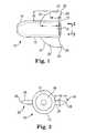
- FIG. 1illustrates as side view of an embodiment of a self-fixating tip.
- FIG. 2illustrates an end view of an embodiment of a self-fixating tip.
- FIGS. 3A , 3 B, 3 C, 3 D, and 3 Eillustrate side views of various embodiments of needle tips.
- FIG. 3Fillustrates an embodiment of an insertion tool.
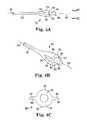
- FIGS. 4A and 4Billustrate a side view and a perspective view of an embodiment of needle tip.
- FIG. 4Cillustrates an end view of an embodiment of a needle tip.
- FIGS. 4D and 4Eillustrate a side view and a tip view, respectively, of a needle tip engaged with a self-fixating tip.
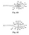
- FIGS. 5A and 5Billustrate a side view and a bottom view, respectively, of a combination of an implant that includes a self-fixating tip, engaged with a needle tip, each also engaged with a guide.
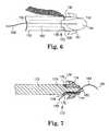
- FIG. 6illustrates an embodiment of a needle tip engaged with a self-fixating tip.
- FIG. 7illustrates an embodiment of a needle tip engaged with a self-fixating tip.
- FIGS. 8A and 8Billustrate two different configurations of an embodiment of a needle tip engaged with a self-fixating tip, the needle tip and self-fixating tip also being engaged with a guide.
- FIG. 9illustrates an embodiment of a needle tip engaged with a guide, the guide also being engaged with a self-fixating tip of an implant.
- FIG. 10illustrates an embodiment of a needle tip engaged with a guide, the guide also being engaged with a self-fixating tip of an implant.
- the inventionrelates to surgical instruments, assemblies, combinations (e.g., of implants and tools), and implantable articles for treating pelvic floor disorders such as prolapse (e.g., vaginal prolapse), incontinence (urinary and fecal incontinence), conditions of the pelvic floor such as the perineal body, conditions of levator muscle (such as a component of levator muscle), conditions of the levator hiatus, and combinations of two or more of these.
- a surgical implantcan be used to treat a pelvic condition, wherein the method includes placing an implant in a manner to support tissue of the pelvic region in a male or female. Methods involve the use of an implant and insertion tool, the implant including at least one self-fixating tip that becomes implanted into tissue of the pelvic region.
- implants and toolscan be designed and used according to the current description in a manner that allows for placement and adjustment of a self-fixating tip.
- the adjusting methodsmay be by using an insertion tool to insert the self-fixating tip to place the self-fixating tip at an initial position, checking the position of the self-fixating tip or implant to identify whether adjustment is necessary or desired, and then using the insertion tool again to move the self-fixating tip to a deeper position within tissue, or, alternately, to move the self-fixating tip to a position of less tissue penetration relative to a position of initial placement.
- a tool and self-fixating tipcan be designed for use in conjunction with a guide that facilitates re-engaging the needle tip and self-fixating tip previously implanted at tissue.
- the insertion toolincludes a needle, and the needle includes an aperture at the needle tip that is capable of engaging the guide.
- the guidecan be used in conjunction with the aperture to allow a user to lead the needle tip to the self-fixating tip of the implant, and engage (or re-engage) the self-fixating tip, after the self-fixating tip has been initially placed in tissue of the pelvic region. Upon engagement (or re-engagement), the position of the self-fixating tip can be adjusted as desired, by further insertion into the tissue.
- the toolmay be dis-engaged from the self-fixating tip, and the position of the self-fixating tip or implant can then be checked to identify whether adjustment is necessary or desired. If adjustment is necessary or desired, the guide can be used to re-engage the needle tip with the self-fixating tip implanted at pelvic tissue. Upon the needle tip being re-engaged with the self-fixating tip, the needle may be used to cause the self-fixating tip to be pushed to a deeper position within tissue.
- the self-fixating tipcan include a lateral extension and the tool can be designed to include an extension guard.
- the extension guardbecomes positioned proximal to the lateral extension to reduce the amount of force required to move the self-fixating tip in a direction opposite of the direction of insertion.
- the engagement of the tool and the self-fixating tipmay be not disturbed (i.e., the tool can remain engaged with the self-fixating tip implanted at pelvic tissue) while the position of the self-fixating tip or implant is checked to identify whether adjustment is necessary or desired. If adjustment is necessary or desired, the insertion tool can be used to move the self-fixating tip to a deeper position within tissue, or, alternately, to a position of less tissue penetration.
- a guidemay not be required to assist in re-engaging the needle tip with the self-fixating that has been implanted in the pelvic tissue.
- An implantcan include a tissue support portion (or “support portion”) that can be used to support pelvic tissue such as the bladder or urethra (which includes any location of the bladder, urethra, bladder neck, mid-urethra, or proximal end of the urethra), vaginal tissue, tissue of the perineum, coccygeus, levator ani, levator hiatus, rectum, etc., as discussed herein.
- the tissue support portionis typically placed in contact with and optionally attached to tissue to be supported, such as with a suture, biological adhesive, mechanical attachment, or any other mode of attachment.
- An implantcan additionally include one or more extension portion (otherwise known as “end” portions or “arms”) attached to the tissue support portion.
- pelvic implantsare described in the following exemplary documents: U.S. Pat. No. 7,070,556; United States patent publication numbers 2005/0245787; 2006/0195011; 2006/0195010; 2006/0235262; 2006/0287571; 2006/0195007; 2006/0260618; 2006/0122457; 2005/0250977; and International patent application number PCT/US2006/028828, having an International Filing Date of Jul. 25, 2006; International patent application, number PCT/US2007/016760, having an International Filing Date of Jul. 25, 2007; International patent application number PCT/US2007/014120, having an International Filing Date of Jun. 15, 2007; and International patent publication WO 2007/097994, the entireties of each of these disclosures being incorporated herein by reference.
- An implantmay include portions or sections that are synthetic or of biological material (e.g., porcine, cadaveric, etc.). Extension portions may be, e.g., a synthetic mesh such as a polypropylene mesh.
- the tissue support portionmay be synthetic (e.g., a polypropylene mesh) or biologic.
- implant productsthat may be similar to those useful according to the present description, include those sold commercially by American Medical Systems, Inc., of Minnetonka Minn., under the trade names Apogee® and Perigee® for use in treating pelvic prolapse (including vaginal vault prolapse, cystocele, enterocele, etc.), and Sparc®, Bioarc®, and Monarc® for treating urinary incontinence.
- Exemplary implantscan include a tissue support portion for placing in contact with tissue to be supported and one or more “extension” portion, the tissue support portion being useful to support a specific type of pelvic tissue such as the urethra, bladder (including the bladder neck), vaginal tissue (anterior, posterior, apical, etc.), perineum, rectum, levator ani, coccygeus, tissue of the pelvic floor, or other tissue of the pelvic region.
- the tissue support portioncan be sized and shaped to contact the desired tissue when installed, e.g., as a “sling” or “hammock,” to contact and support pelvic tissue.
- a tissue support portion that is located between two or more extension portionsis sometimes referred to herein as a “central support portion” or a “support portion.”
- Extension portionsare elongate pieces of material that extend from the tissue support portion and either are or can be connected to the tissue support portion, and are useful to attach to an anatomical feature of the pelvic region (e.g., using a self-fixating tip) to thereby provide support for the tissue support portion and the supported tissue.
- One or multiple (e.g.; one, two, or four) extension portionscan extend from the tissue support portion as elongate “ends,” “arms,” or “extensions,” useful to attach to tissue in the pelvic region.
- An example of a particular type of pelvic implantis the type that includes supportive portions including or consisting of a central support portion and either two, four, or six elongate extension portions extending from the central support portion.
- An implant that has exactly two extension portionscan be of the type useful for treating, e.g., urinary incontinence, anterior vaginal prolapse, or posterior vaginal prolapse.
- An implant having four or six extension portionscan be useful for treating combinations of these conditions.
- supportive portionsrefers to extension portions and tissue support portions and does not include optional or appurtenant features of an implant or implant system such as a sheath, self-fixating tip or other type of connector for attaching the implant to an insertion tool, guide, etc.
- implants for treating incontinencecan include a central support portion and two extension portions, and may take the form of an integral mesh strip.
- An exemplary urethral slingcan be an integral mesh strip with supportive portions consisting of or consisting essentially of a central support portion and two extension portions.
- Examples of urethral slings for treating male urinary incontinencecan have a widened central support portion, as discussed, for example, in Assignee's copending United States patent publication numbers 2006/0287571 and 2006/0235262.
- Other exemplary urethral sling implantsare described in Assignee's U.S. Pat. No. 7,070,556; United States publication numbers 2006/0195010 and 2006/0195007; and International application numbers WO 2007/097994 and WO 2007/014120; among others.
- implants for treating vaginal prolapsecan comprise a central support portion and from two to four to six extension portions, and may take the form of an integral piece of mesh or multiple pieces of mesh attached in a modular fashion. See, e.g., Assignee's copending United States patent publication numbers 2006/0260618; 2005/0245787; 2006/0122457; 2005/0250977; and International patent application number PCT/2006/028828; among others.
- implants for treating conditions of the pelvic floormay take the form of an integral piece of mesh or multiple pieces of mesh attached in a modular fashion. See, e.g., International patent application number PCT/US2007/016760, filed Jul. 25, 2007, by Kimberly Anderson, entitled SURGICAL ARTICLES AND METHODS FOR TREATING PELVIC CONDITIONS.
- Dimensions of an implantcan be as desired and useful for any particular installation procedure, treatment, patient anatomy, and to support or repair a specific tissue or type of tissue. Exemplary dimensions can be sufficient to allow the tissue support portion to contact tissue to be repaired or supported, and to allow extension portions to extend from the tissue support portion to a desired anatomical location to allow the extension portion be secured to anatomy of the pelvic region, to support the tissue support portion.
- extension portionscan allow an extension portion to reach between a tissue support portion placed to support pelvic tissue (at an end of the extension portion connected to the tissue support portion) and a location at which the distal end of the extension portion attaches to pelvic tissue.
- a distal end of an extension portioncan include a self-fixating tip that can be attached directly to pelvic tissue such as pelvic muscle, ligament, or tendon.
- the length of the extension portiontherefore, can be in a range that allows placement of a tissue support portion as desired to support pelvic tissue, while the self-fixating tip is placed in pelvic tissue.
- a length of an extension portioncan optionally be fixed (i.e., the extension portion does not include any form of length-adjusting mechanism), as can a length of an implant spanning from opposite self-fixating tips and including extension portions and a length or segment of tissue support portion.
- Alternate implantsmay include adjustment or tensioning mechanisms that allow a physician to alter the length of an extension portion before, during, or after implantation: e.g., International application number PCT/US2007/014120, filed Jun. 15, 2007, by Dockendorf et al., titled SURGICAL IMPLANTS, TOOLS, AND METHODS FOR TREATING PELVIC CONDITIONS.
- adjustment and tensioning mechanismscan also be excluded from embodiments of implants of the invention by selecting the length of extension portions and tissue support portions, and by adjusting for tensioning or positioning of extension portions and tissue support portions based on placement of the self-fixating tip within the pelvic tissue, selected placement including selection of the point of insertion of a self-fixating tip and depth of insertion of the self-fixating tip, and by use of adjustment steps described herein that include options of initial placement of a self-fixating tip followed by adjustment to place the self-fixating tip either deeper or less deep into tissue relative to the initial placement position.
- An extension portion of an implantcan include a self-fixating tip at an end of the extension portion that is distal from a tissue support portion.
- the self-fixating tipin general can be a structure connected to a distal end of an extension portion and that can be implanted into tissue in a manner that will maintain the position of the self-fixating tip and the attached implant.
- a self-fixating tipcan also be designed to engage a distal end of an insertion tool so the insertion tool can be used to push the self-fixating tip into tissue for implantation, then optionally adjust the placement.
- the self-fixating tipmay engage the insertion tool at an internal channel of the self-fixating tip, at an external location such as at the base, or at a lateral extension, as desired.
- a self-fixating tipcan be made out of any useful material, generally including materials that can be molded or formed to a desired structure and connected to or attached to an end of an extension portion of an implant.
- Useful materialscan include plastics such as polyethylene, polypropylene, and other thermoplastic or thermoformable materials, as well as metals, ceramics, and other types of biocompatible and optionally bioabsorbable or bioresorbable materials.
- Exemplary bioabsorbable materialsinclude, e.g., polyglycolic acid (PGA), polylactide (PLA), copolymers of PGA and PLA, and the like.
- a self-fixating tipalso, preferably, includes one or more lateral extension that can increase the force required to remove the self-fixating tip from tissue after insertion into the tissue, i.e. the “pullout force.”
- a lateral extensioncan be designed to exhibit a reduced or relatively low “insertion force,” which is the amount of force used to insert the self-fixating tip into tissue.
- Embodiments of self-fixating tipscan be designed to be essentially permanently placed upon insertion into tissue, except that according to methods described herein, a self-fixating tip can be initially placed then adjusted as described.
- Factors that can be balanced in designing a self-fixating tip as describedinclude insertion force and pullout force, the insertion force being preferably reduced or minimized while a pullout force allows removal of the self-fixating tip only when desired by a surgeon during an implantation procedure.
- the self-fixating tip designcan attempt to minimize the amount of potential trauma caused to tissue by inserting or, when necessary, removing, a self-fixating tip.
- a desired combination of these factorscan be achieved by selecting size, shape, and other structural features of the self-fixating tip and the elements of the self-fixating tip such as a base and lateral extensions.
- a self-fixating tipcan have from one to any desired number of lateral extensions, but it has been found that a self-fixating tip can function well with a small number of fixed lateral extensions such as two, three, or four lateral extensions.
- embodiments of self-fixating tipscan include two or more lateral extensions located at the same position along the longitudinal dimension (length) of the base between a proximal base end and a distal base end.
- a self-fixating tip that includes exactly two lateral extensionscan include two self-fixating tips that are located opposite of each other along a length of a base, to provide desired insertion and pullout forces, especially by implanting the two lateral extensions to be oriented in fibrous tissue with the direction of the lateral extensions being not parallel to the tissue fibers, for example being perpendicular to the fibers (or “across the grain”). Also, a relatively low number of lateral extensions, such as two, can desirably reduce the amount of trauma when, as may become necessary at the discretion of a surgeon during implantation, a self-fixating tip must be adjusted or withdrawn from tissue after placement.
- a self-fixating tipfor use according to the present description can be sizes of a base, lateral extension, or both, to allow the self-fixating tip to be inserted into tissue at a selected depth.
- a lateral extension that will be placed into muscle tissuecan have a length dimension (measured along a longitudinal axis of the base) that allows the self-fixating tip to be inserted into the tissue at any selected depth along the thickness of the tissue. This can mean that the length dimension of the lateral extension is shorter than the total depth of tissue (e.g., muscle or other tissue) into which the self-fixating tip will be placed.
- a base of a self-fixating tipcan be of any desired size, shape, and dimension (e.g., length, diameter, width).
- a diameter of a cylindrical basecan be any useful size, for example from about 2 to about 5 millimeters. The diameter may be uniform along the length of the base, between a base proximal end and a base distal end, or a diameter may be non-uniform. For example, a diameter of a base may be greater at a proximal end and taper to a reduced diameter at a distal end, to optionally reduce insertion force or increase pullout force.
- the diameter or diameter profile of a basemay preferably be relatively small, e.g., minimized, to reduce trauma to tissue when implanted or removed. The diameter can also be sufficient to allow placement of a desired number of lateral extensions around the perimeter of the base.
- Exemplary self-fixating tips described hereininclude a cylindrical base or tapered cylindrical base, with a hollow or solid interior.
- Other shapes for a basemay also be useful, such as blocks having square or rectangular forms when viewed in cross section along a longitudinal axis extending from a proximal base end to a distal base end.
- dimensions of a square or rectangular cross sectioncan be of a range similar to the described range of diameters of a cylindrical base, such as from about 2 to about 5 millimeters in either dimension when viewed in cross section.
- lengths(measured from the proximal base end to the distal base end along a longitudinal axis of the self-fixating tip) in the range from 0.4 to 1.0 centimeter, e.g., from 0.4 to 0.8 centimeters, or from 0.4 to 0.7 centimeters, have been found to be useful.
- These rangesare specifically useful for self-fixating tips that can be inserted into tissue of the obturator internus, because the relatively short length can allow the self-fixating tip to be inserted into the muscle tissue a desired depth, i.e., over a range of depths, optionally without penetrating the obturator membrane.
- the self-fixating tipcan be of a length dimension that is less than the thickness of muscle or other pelvic tissue into which the self-fixating tip is to be inserted, so the self-fixating tip can be inserted a desired distance into the tissue.
- a self-fixating tipcan have structure that includes a base having a proximal base end and a distal base end.
- the proximal base endcan be connected (directly or indirectly, such as by a connective suture) to a distal end of an extension portion of an implant.
- the baseextends from the proximal base end to the distal base end and can optionally include an internal channel extending from the proximal base end at least partially along a length of the base toward the distal base end.
- the optional internal channelcan be designed to interact with (i.e., engage) a distal end of an insertion tool (e.g., a needle tip) to allow the insertion tool to be used to place the self-fixating tip at a location within pelvic tissue of the patient.
- the channelcan be an aperture that extends through the entire length of the base to allow a guide to be loosely engage by the self-fixating tip.
- Alternate embodiments of self-fixating tipsdo not require and can exclude an internal channel for engaging an insertion tool.
- These alternate embodimentsmay be solid, with no internal channel, and may engage an insertion tool, if desired, by any alternate form of engagement, such as by use of an insertion tool that contacts the self-fixating tip at an external location, for example by grasping or otherwise contacting the base (on a side or at the face of the proximal base end) or by grasping or otherwise contacting a lateral extension.
- Exemplary lateral extensionscan be rigid or “fixed” relative to the base so the lateral extension does not substantially move or deflect during or after implantation.
- a fixed lateral extensioncan be a lateral extension that is not substantially moveable relative to the base in a manner that certain types of known soft tissue anchor extensions are moveable, for instance between a non-deployed or non-extended position that places an extension against the base to allow insertion of the anchor into tissue with a reduced size or shape profile, and a deployed or extended position that places the extension away from the base to engage tissue and prevent movement of the self-fixating tip in a direction opposite of the direction of insertion.
- lateral extensionscan be moveable or deflectable, if desired, such as to allow a reduced insertion force by use of lateral extensions that deflect backward (toward the proximal base end or against the base) when a self-fixating tip is being pushed through tissue.
- a lateral extensioncan have a three-dimensional form that results in a balance of the performance factors described herein, including insertion force, pullout force, and reduced trauma caused to tissue during insertion or in the event of a need to adjust or remove the self-fixating tip during an implantation procedure.
- a lateral extensioncan include a three-dimensional form referred to as an extension body defined as the lateral extension material between a leading edge, a trailing edge, and a boundary at which the lateral extension connects to a base.
- the far lateral edge of a lateral extensionmay include a point of connection of the trailing edge and the leading edge; alternately, another segment or connection may connect the leading edge with the trailing edge away from their respective connections to the base.
- the “leading edge”means the boundary of the lateral extension on the side of the lateral extension toward the base distal end, which is also the edge that leads the lateral extension body and contacts tissue first as the self-fixating tip is being inserted into tissue by pushing.
- the “trailing edge”means the boundary of the lateral extension on the side of the lateral extension toward the base proximal end, which is also the edge that trails behind the lateral extension body and passes through or contacts tissue last when the self-fixating tip is being inserted into tissue by pushing.
- the lateral extension bodycan exhibit a thickness or thickness profile as desired, such as a uniform thickness or a varied thickness across the extended area of the lateral extension body.
- implantsmay include a leading edge of a low profile, e.g., reduced thickness or even sharpened, to allow for reduced insertion force.
- the thickness of the lateral extension bodycan reduce gradually or taper from a central portion of the body (away from edges) in the direction of a leading edge.
- a leading edgebeing of a reduced thickness to reduce insertion force, may optionally in addition exhibit a form that extends in a direction back toward the trailing edge, i.e., a “swept-back” leading edge, to reduce insertion force.
- leading edgemay be linear or arcuate, and if arcuate may be convex or concave.
- a leading edgemay take an arcuate convex path that sweeps back to meet the trailing edge at a single lateral extension point away from the base. E.g., see the exemplary self-fixating tip illustrated at FIG. 1 .
- the direction and shape of a trailing edge of a lateral extensionmay be linear or arcuate, and if arcuate may be convex or concave relative to the lateral extension body.
- a trailing edgecan be as desired, such as arcuate, straight, convex, flat, linear, rounded, tapered, sharp, blunt, etc.
- a trailing edgecan exhibit a thickness (a thickness dimension, t, is illustrated, e.g., at FIG. 2 ) to produce increased pullout force.
- a trailing edgecan exhibit an area that includes a width (W, the distance the trailing edge extends laterally away from the base) and a thickness (t, the distance perpendicular to the width and the longitudinal axis of the self-fixating tip).
- An exemplary width of a trailing edgecan be, e.g., in the range from 0.5 to 3 millimeters.
- An exemplary thickness at a trailing edgemay be the same as a thickness at an interior or central portion of the lateral extension (away from the leading and trailing edges), or a thickness at a trailing edge may be a maximum thickness of the entire lateral extension, meaning for example that the thickness increases from a narrow thickness at the leading edge and widens gradually to a maximum thickness at the trailing edge.
- a thickness of a trailing edgecan be, e.g., in the range from 0.2 to 2 millimeters, e.g., from 0.5 to 1.5 millimeters.
- a surface area of a trailing edgemay be, e.g., from the range from 0.25 to 5 square millimeters, e.g., from 0.5 to 4, or from 1 to 3 square millimeters.
- the surface area of the trailing edgemay be concave, convex, rounded, tapered (symmetrically or toward one or the other surfaces of the lateral extension), etc.
- a lateral extensioncan also include a third dimension that can be referred to as a “length” dimension (shown as “L” at FIG. 1 ).
- a lengthcan be measured at a location where the lateral extension meets or extends from the base. This length dimension can become smaller as the lateral extension extends away from the base.
- An exemplary length of a lateral extension at the location of the lateral extension meeting the basecan be, e.g., from 0.5 to 5 millimeters, such as from 1 to 4 millimeters or from 1.5 to 3.5 millimeters.
- an exemplary length of a lateral extensioncan be a length that is less than the total thickness of obturator foramen tissue (i.e., the combined thickness of obturator internus muscle, obturator, membrane, and obturator externus muscle); a length of a lateral extension intended to be inserted into the obturator internus muscle can be a length that is a portion of the thickness of the obturator internus muscle, e.g., less than 1 centimeter, such as less than 0.5 centimeter.
- a self-fixating tipcan include multiple lateral extensions at multiple locations, either at different positions along a length of a base, at different locations around a perimeter of a base, or both.
- a self-fixating tipmay preferably include all lateral extensions originating from the same position along a length of a base, e.g., a single set of lateral extensions can be arranged around a perimeter of a base, each extending in a different direction but from the same portion of length between the proximal base end and the distal base end.
- a self-fixating tipcan be connected to an extension portion of an implant in any fashion, directly by any attachment mechanism, or indirectly such as through an attachment structure such as a suture.
- a connectioncan be based on a mechanical structure, by adhesive, by a connecting suture, or by an integral connection such as by injection molding or “insert” molding (also, “overmolding”) as described U.S. Publication No. 2006/0260618-A1, incorporated herein by reference.
- a thermoplastic or thermosetting polymer materialcan be insert molded or injection molded at an end of a mesh extension portion of an implant, e.g., directly to the mesh.
- a molded polymercan form a self-fixating tip at an end of an extension portion.
- the self-fixating tipcan be as described herein, for example, including lateral extensions and an internal channel.
- FIG. 1shows self-fixating tip 10 , including base 12 (for attachment to an implant extension end), proximal base end 14 , distal base end 16 , internal channel 18 , and two lateral extensions 20 located on outer surfaces and on opposite sides of base 12 .
- Self-fixating tip 10can be prepared from a biocompatible material, preferably a biocompatible material such as a biocompatible polymer, which may optionally be bioresorbable or bioabsorbable.
- Exemplary self-fixating tip 10 as illustratedincludes internal channel 18 (optional according to the invention) which is an opening within base 12 extending from proximal end 14 toward distal end 16 along at least a portion of the total longitudinal length of base 12 .
- Internal channel 18is capable of receiving a distal end (e.g., needle tip) of an elongate needle of an insertion tool to allow self-fixating tip 10 to be pushed into position within pelvic tissue during an implant installation procedure.
- Channel 18optionally and as illustrated can be an “aperture” or “bore” that extends entirely through base 12 , from proximal base end 14 to distal base 16 , allowing a guide to be threaded loosely within channel 18 .
- Lateral extensions 20include leading edge 24 and trailing edge 26 .
- Leading edge 24originates at base 12 and extends away from base 12 along an arcuate pathway sweeping back toward proximal base end 14 , meeting trailing edge 26 at point 28 .
- Leading edge 24can preferably include a reduced thickness or a sharp or sharpened edge.
- Trailing edge 26is shown to be relatively straight but could alternately be arcuate, concave, or convex (from the direction viewed in FIG. 1 ). Trailing edge 26 has a flat surface area (not visible at FIG. 1 ), but could also be arcuate, concave, or convex. Trailing edge 26 is shown to sweep slightly back in a proximal direction, although it could alternately extend straight away from (i.e. perpendicular to) base 12 or extend away from base 12 in a direction that includes a forward component, i.e., a directional component in the direction of distal base end 16 .
- self-fixating tip 10is viewed in a direction looking at proximal base end (surface) 14 along a longitudinal axis of base 12 .
- surface areas of lateral extensions 20are shown as flat surfaces of approximately the area of thickness (t) by width (W).
- Wwidth
- a surface area within self-fixating tip 10that fixes the rotational position of the self-fixating tip relative to a longitudinal axis of a needle tip of an insertion tool, such as a flat surface, a key, etc.
- a surface to fix the rotational position of the self-fixating tip relative to a longitudinal axis of the needle tipcan be particularly useful in embodiments of the invention that include a needle having extension guards.
- Embodiments of self-fixating tipsmay engage a guide.
- a “guide”refers to an elongate element that can also engage an aperture of a needle tip.
- a guidemay be a thread, suture, plastic or metal wire, or the like, that includes at least one end that can be loose to extend from a self-fixating implanted in pelvic tissue to a location external to a patient's body, during a procedure for installing the self-fixating tip, and that optionally includes two loose ends that can both at the same time extend from a self-fixating tip to a location external to a patient's body during a procedure for installing the self-fixating tip.
- the guidemay be of any useful dimensions.
- An exemplary lengthmay be from 10 to 60 centimeters, e.g., from 20 to 50 centimeters.
- An exemplary diametermay be from 0.1 to 2 millimeter, e.g., from 0.2 to 1 millimeter.
- a single example of a guidecan be 2-0 suture material.
- a self-fixating tip being “engaged with” a guiderefers to an association between a self-fixating tip and a guide, during use, wherein the guide engages the self-fixating tip in a fixed manner such as a permanent attachment, or a loose manner such as a manner by which the guide can support the self-fixating tip as the self-fixating tip is moveable along a length of the guide.
- a self-fixating tip engaged with a guiderefers to a self-fixating tip that is securely attached to a guide in a fixed manner such as by being tied to the self-fixating tip, embedded within the self-fixating tip (e.g., by molding the self-fixating tip around a guide), or adhered by any type of mechanical fastener or adhesive (see, for example, FIGS. 6 and 8 ).
- a self-fixating tip engaged with a guidealso refers to a self-fixating tip that is loosely engaged through an aperture of a self-fixating tip (see, for example, FIGS. 5A , 5 B, and 7 ).
- a self-fixating tip engaged with a guiderefers to a self-fixating tip that loosely engages a guide such as through an aperture, and that can become more securely fixed relative to the self-fixating tip at least on one direction; for example a guide may be contained by an aperture of a self-fixating tip and may include a structure such as a knot or other structure that is larger in diameter compared to a diameter of the aperture so that the structure (e.g., knot) is capable of contacting the self-fixating tip to become fixed at a location of the self-fixating tip in a manner that allows the guide to encounter resistance within the self-fixating tip.
- the knot or other structurecan become lodged at the aperture to allow the guide to place force on the self-fixating tip and to pull the self-fixating tip (see, for example, FIG. 9 ).
- An insertion toolcan be used to install the implant.
- Various types of insertion toolsare known and these types of tools and modified versions of these tools can be used according to the present description, to install an implant as described.
- useful toolsinclude those types of tools that generally includes a thin elongate needle that attaches to a handle; a handle attached to one end (a proximal end) of the needle; and a distal end of the needle adapted to engage a self-fixating tip in a manner that allows the needle to push the self-fixating through a tissue path and insert the self-fixating tip into tissue of the pelvic region.
- This class of toolcan be used with a self-fixating tip that includes an internal channel designed to be engaged by a distal end of an insertion tool.
- insertion toolswill also be useful by engaging a self-fixating tip in a manner that does not involve an internal channel of a self-fixating tip.
- These alternate insertion toolsmay for example contact or grasp a proximal base end of a self-fixating tip in the absence of an internal channel, such as by grasping an external surface of the base.
- An alternate insertion toolmay contact or grasp a side of the base, a lateral extension, or any other portion of the self-fixating tip or base, in a way that allows the insertion tool to engage the self-fixating tip and insert the self-fixating tip at a desired location within tissue of the pelvic region.
- Exemplary insertion tools for treatment of pelvic conditionsare described, e.g., in U.S. Pat. No. 7,070,556; United States patent publication numbers 2005/0245787, 2006/0235262, 2006/0260618, and 2005/0250977; and International patent application numbers PCT/US2006/028828 and PCT/2007/016760, among others.
- the tools of the above-referenced patent documentsmay be curved in two or three dimensions and may include, for example, a curved portion for placing an extension portion of an implant through a tissue path that passes from a region of the urethra to tissue of an obturator foramen, or another pelvic tissue location.
- Exemplary insertion tools for use according to the inventioncan be similar to or can include features of tools described in the above-referenced patent documents.
- those insertion toolsmay be modified to allow the insertion tool to be used to place a self-fixating tip at tissue within the pelvic region by methods described herein, including initial placement of a self-fixating tip followed by optional adjustment of the self-fixating tip.
- the insertion toolcan be designed, shaped, and sized, to include an elongate inserter or “needle” that may be straight or that may be curved in two or three dimensions, that can be inserted through an incision that provides access to the pelvic region.
- the incisionmay be, for example, a vaginal incision (for female anatomy), a perineal incision (for male anatomy), or an incision in the rectal or buttock region, inner thigh or groin, pubic region, etc.
- Some previous insertion toolsare designed to reach through a vaginal or perineal incision, through an internal tissue path, and to then extend through a second external incision, e.g., at the inner groin, thigh, abdominal area, or perirectal region.
- Alternate insertion tools also useful with embodiments of the presently-described methodscan be sized and shaped to place a self-fixating tip at an internal location of the pelvic region without the need to be sufficiently long to extend from a vaginal or perirectal incision to another (e.g., external) incision.
- the lengthcan be only sufficient to reach from a vaginal or perirectal incision to an obturator foramen, for example, or to any other location within the pelvic region at which a self-fixating tip is desirably placed.
- the lengthmay be sufficient, for example, to reach from a vaginal or perirectal incision to a different muscle or tissue, such as a levator ani, coccygeous muscle, iliococcygeous muscle, arcus tendineus, sacrospinous ligament, etc., to place a self-fixating tip at one of those tissues.
- a toolcan include a handle, needle (including a shaft), needle tip, and needle tip end.
- the handleis at the portion of the tool that will be referred to as a proximal end, and the needle tip is at a distal end.
- a proximal end of the needleconnects to a distal end of the handle.
- the “needle tip”refers to a length of a needle that is at the far distal end, including a needle tip end, which is the most distal location of the needle.
- the needle tipincludes a portion of the needle that (if included) is designed to engage a self-fixating tip, and also may be considered to include a small amount of length (e.g., 1 centimeter or 2 centimeters) of the needle shaft adjacent to the surfaces designed to engage a self-fixating tip.
- Some embodiments of tools for use as described hereincan include a needle tip that includes an aperture that allows the needle tip to engage a guide.
- an “aperture”is a feature at a needle tip that can engage a guide to allow the needle to move in a guided fashion along a length of the guide. This, for example, allows a user to use the guide to move the needle tip into engagement with a self-fixating tip (which is also engaged with the same guide), after the self-fixating tip has been placed at tissue of a pelvic region.
- the apertureis designed to allow the needle tip to engage the self-fixating tip while the needle tip is engaged with the guide. This allows the needle tip to engage the self-fixating tip, located at tissue of a patient's pelvic region, and allow the self-fixating tip to be adjusted after initial placement at tissue of a pelvic region.
- An aperture at a needle tipcan include a circular or cylindrical bore, or a functional equivalent, that can be, e.g., along a longitudinal axis of the needle tip, parallel to a longitudinal axis of the needle tip, diagonal relative to a longitudinal axis of the needle tip but through the axis, diagonal relative to a longitudinal axis of the needle tip and also either through or not through the axis, etc.
- a boremay be cylindrical, but may also be square, rectangular, or any other geometry.
- An aperturemay be substantially linear or curved along a length extending along a length of the needle tip or needle shaft.
- An embodiment of a bore portion of an aperturemay extend from a needle tip end or any other surface of a needle tip, in a direction along the needle toward the proximal end of the needle.
- An aperturecan include a bore that connects to a slot or a channel at a surface of the needle tip, within which the guide may be loosely contained.
- An aperturemay be arcuate, e.g., cylindrical, or partially cylindrical in cross section, with a dimension that can engage a guide, e.g., may include a diameter in the range from 0.10 to 2 millimeters, preferably from 0.5 to 1.5 millimeters.
- a length dimension of an aperture(include a bore, channel, or both) can be, e.g., in the range from 0.1 millimeter, to a length of a needle shaft or an insertion tool, including a handle, (e.g., if a shaft or tool is fully cannulated). Alternate length dimensions can be sufficient for an aperture to extend along a portion of a length of a needle tip.
- needle tip 30includes needle shaft 32 , narrowed portion 34 , and shoulder 36 that connects shaft 32 with narrowed portion 34 .
- Narrowed portion 34is designed to engage a channel that extends within a base of a self-fixating tip (not shown).
- Aperture 38is a continuous cylindrical bore that extends from needle tip end 40 , through narrowed portion 34 , and through a portion of needle shaft 32 , including a curved portion that allows aperture 34 to exit at a surface of needle shaft 32 .
- Aperture 38 extending from needle tip end 40 to needle shaft 32is capable of engaging a guide, which can be threaded through the aperture.
- the guidecan be threaded through the aperture and the needle tip can be led along the guide to a desired location of anatomy of a patient; the guide can at the same time be engaged with a self-fixating tip that has been placed at pelvic tissue of a patient.
- the needle tipcan then engage the self-fixating tip previously placed within the tissue, allowing the insertion tool to be used to adjust the location of the self-fixating tip.
- needle tip 41includes needle shaft 42 , narrowed portion 44 , and shoulder 46 that connects shaft 42 with narrowed portion 44 .
- Narrowed portion 44is designed to engage a channel within a base of a self-fixating tip (not shown).
- Aperture 48includes a cylindrical bore, 49 , that begins at needle tip end 50 and extends generally along a longitudinal axis (or slightly diagonally to the axis) of needle tip 50 into narrowed portion 44 .
- aperture 48includes open channel (or “slot” or “recess”) 52 within which a guide can fit, such as when needle tip 41 engages a self-fixating tip.
- Channel 52extends along a surface of narrowed portion 44 , along shoulder 46 , and along a distance of shaft 42 .
- Aperture 48extending from needle tip end 50 to needle shaft 52 , is capable of engaging a guide, which can be threaded through bore 49 and contained by aperture 48 while needle tip 50 engages a self-fixating tip.
- the guidecan be threaded through bore 49 and the needle tip can be led along the guide to a desired location of anatomy of a patient; the guide can at the same time be engaged with the self-fixating tip previously placed at the location of anatomy.
- the needle tipcan then engage a self-fixating tip previously placed within tissue at that location, while the guide is contained by aperture 48 , and the insertion tool can be used to adjust the location of the self-fixating tip.
- FIG. 3Cillustrates a rotated view of needle tip 41 shown at FIG. 3B .
- This viewagain shows aperture 48 , including cylindrical bore 49 that begins at needle tip end 50 and extends generally along a longitudinal axis of needle tip 50 , into narrowed portion 44 .
- Open channel (or “slot” or “recess”) 52is shown directly as being defined by a recessed surface extending along narrowed portion 44 , within which a guide can fit. Channel 52 extends along a surface of narrowed, portion 44 , along shoulder 46 , and along a distance of shaft 42 .
- needle tip 60includes needle shaft 62 , tapered portion 64 , and aperture 68 .
- Tapered portion 34can be designed to engage an opening within a base of a self-fixating tip (not shown), or may be designed for insertion into tissue in a manner that allows a guide to be pulled through aperture 68 ; with needle tip 60 placed in tissue of the pelvic region, a loose end of the guide can be pulled to cause a self-fixating tip to be pulled into the tissue.
- Aperture 68is a continuous cylindrical bore that extends from a surface at tapered portion 64 , in a direction that is diagonal, proximally toward shaft 62 , exiting at shaft 62 at or near the proximal side of tapered portion 64 .
- needle tip 70includes needle shaft 72 , tapered portion 74 , and aperture 78 .
- Tapered portion 74can be designed to engage an opening within a base of a self-fixating tip (not shown), or may be designed for insertion into tissue in a manner that allows a guide to be pulled through aperture 78 ; with needle tip 70 placed in tissue of the pelvic region, a loose end of the guide can be pulled to cause a self-fixating tip to be pulled into the tissue.
- Aperture 78is a continuous cylindrical bore that extends transversely through tapered portion 74 of needle tip 72 .
- FIG. 3Fillustrates an insertion tool that includes a needle tip having an aperture.
- tool 120includes handle 122 that includes handle distal end 124 .
- Needle 126includes proximal end 128 attached to handle distal end 124 .
- Needle distal end 130include needle tip 132 that includes aperture 134 .
- Mark 136which may be a groove or other marking, can function to mark a reference point at which the mark can be located when needle tip 132 is properly located to place a self-fixating tip at tissue of the pelvic region.
- mark 136may indicate the midline of a patient, e.g., below the urethra, when the needle tip is placed for implanting a self-fixating tip at tissue of the pelvic region. This allows the surgeon or other user to avoid causing a self-fixating tip to be penetrated too deeply in desired tissue.
- a mark such as mark 136may also be used to mark a reference point relative to a location of an implant, e.g., by corresponding to a midline or other location of an implant, to allow a surgeon or other user to assess the distance of the needle tip relative to that location; a mark on a insertion tool needle aligned with a location of the implant, for example, may indicate that the needle tip is engaged with a self-fixating tip at the end of an extension portion of the implant.
- a needle tip of a tool for use according to the present descriptioncan include one or more extension guard at the distal end of the needle at a location where the distal end meets a self-fixating tip.
- An extension guardis an integral or attached portion of an insertion tool, located at the needle, that extends laterally from a needle shaft and that is shaped to correspond to a shape or form of a trailing (proximal) portion of a self-fixating tip when the self-fixating tip is engaged with the needle tip.
- An extension guardcan be integral to a needle or may be a removable piece that can be fit onto the needle and removed as desired, such as a plastic attachment in the form of a tube, clip, or other moveable or attachable and detachable piece that fits the needle at a position along the length of the needle so the extension guards extend laterally.
- the function of the extension guardis to provide streamlining behind (proximal to) a trailing surface of a self-fixating tip, such as behind a lateral extension of a self-fixating tip; the streamlining reduces the force required to remove a self-fixating tip from tissue or to adjust the location of the self-fixating tip in a direction opposite of the direction of insertion.
- the combined form of a needle extension guard situated proximal to a trailing surface of a lateral extension of a self-fixating tipincludes a smooth, e.g., streamlined, form from a leading edge of the lateral extension to a proximal end (trailing edge) of the extension guard.
- the smooth formcan be preferably arcuate and can exclude jagged edges or angles that would increase friction when the self-fixating tip is moved through tissue (e.g., pushed or pulled) while engaged with the needle tip.
- the streamlined formresults in reduced friction, and reduced force, for moving the assembly of self-fixating tip and needle distal end in a direction of insertion, and particularly, in a direction opposite of a direction of insertion.
- needle tip 80is shown at FIG. 4A .
- needle tip 80includes needle shaft 82 , top extension guard 84 , bottom extension guard 86 , pin 88 , and side extension guard 94 .
- Top extension guard 84includes top extension guard face 90 .
- Bottom extension guard 86includes bottom extension guard face 92 .
- Side extension guard 94includes side extension guard face 96 .
- Each of extension guard faces 90 , 92 , and 96can be independently sized to correspond to a size and shape of a trailing (i.e. proximal-facing) surface of a self-fixating tip, such a trailing surface of a lateral extension.
- An extension guard that “corresponds to” a trailing surface of a self-fixating tiprefers to a profile of an extension guard—when looking along a longitudinal axis of the tool—that is substantially the same as a profile of a trailing surface of the self-fixating tip. See, e.g., FIG. 4C and associated text.
- the distal surfaces of the extension guardscorrespond in size and shape to the trailing (proximal) surfaces of the self-fixating tip.
- pin 88is designed to engage an internal channel of a self-fixating tip. While needle tip 80 as illustrated does not include an aperture, as described herein, an aperture as described could be included in needle tip 80 .
- FIG. 4Bis a side profile view of needle tip 80 .
- FIG. 4Cis a front view of needle tip 80 along longitudinal axis 99 of needle tip 80 .
- a feature of a needle tip 80a surface that corresponds to a surface of a self-fixating tip, to cause the needle tip to engage the self-fixating tip at a rotational position so that side extension guards 94 and 95 are oriented proximal to extension portions of the self-fixating tip.
- Control of the rotational position of the self-fixating tip, when engaging the needle tipcan be particularly useful in embodiments of the invention that include a needle having extension guards, so the needle guards are aligned with the extension portions.
- FIGS. 4D and 4Eillustrate needle tip 80 engaged with self-fixating tip 100 .
- Self-fixating tip 100includes base 101 , which includes internal channel 108 that is sized and shaped to engage pin 88 .
- Lateral extensions 102 and 103extend from base 101 .
- Trailing surfaces (i.e., “trailing faces”) of self-fixating tip 100are sized and shaped to correspond to distal surfaces of extension guards at needle tip 80 .
- trailing face 104 of lateral extension 102corresponds with side extension guard face 96 .
- trailing face 105 of base 101corresponds in size and shape with bottom extension guard face 92
- trailing face 106 of base 101corresponds in size and shape with top extension guard face 90 .
- FIG. 1As additionally shown at FIG.
- trailing face 107 of lateral extension 103corresponds with side extension guard face 97 of extension guard 95 .
- channel 108can include a surface that corresponds to a surface of pin 88 that together cause selective rotational engagement between pin 88 and self-fixating tip 100 , to allow engagement only with alignment of distal surfaces 96 and 97 of side extension guards 94 and 95 of the insertion tool, with trailing surfaces 104 and 107 of lateral extensions 102 and 103 of the needle tip, respectively.
- FIGS. 4A , 4 B, 4 C, etc.show extension guards as integral elements of a needle.
- An extension guardcan be integral to a needle as illustrated, but optionally can be removable, such as in the form of a tube that fits over a length of the needle on a proximal side of the needle tip, with side extension guards extending laterally in a position where the side extension guards will be proximal to lateral extension of the self-fixating tip during use.
- incontinencevarious forms such as fecal incontinence, stress urinary incontinence, urge incontinence, mixed incontinence, etc.
- vaginal prolapseincluding various forms such as enterocele, cystocele, rectocele, apical or vault prolapse, uterine descent, etc.
- conditions of the perineal bodyconditions of the pelvic floor including the coccygeous and levator muscle (such as by treating a component of levator muscle, iliococcygeous, coccygeous, levator ani, pubococcygeous), conditions of the levator hiatus, and combinations of two or more of these, and other pelvic conditions caused by muscle and ligament weakness.
- an embodiment of an insertion toolcan be used, as described, wherein the insertion tool can include a needle tip having an aperture capable of engaging a guide, an extension guard, or both.
- the extension guardcan be removable, and a single insertion tool that includes an aperture and a removable extension guard can be used with or without the extension guard within a single surgical implantation procedure.
- Certain embodiments of methods as describedcan include a step of engaging a self-fixating tip (of an implant) with a needle tip of an insertion tool, wherein the needle tip includes an aperture that is capable of engaging a guide, and the self-fixating tip also engages the guide.
- the insertion toolis used to initially place the self-fixating tip at a desired tissue location in the pelvic region.
- the guideincludes one end or portion of a total length that is engaged with the self-fixating tip, and at least one portion (e.g., a proximal portion) that includes an end that remains accessible and outside of the surgical site, optionally two portions each including an end.
- the accessible (loose) portion, end, portions, or endscan remain external to the incision.
- placement of the self-fixating tipcan be assessed to see if adjustment is desired, e.g., by checking tension of the extension portion visually, by feel (e.g., by application of pressure), or by checking patient comfort, continence, etc.
- adjustmentis desired, using a tool having a needle tip with an aperture, an end of the guide can be threaded through the aperture and the guide can be used to lead the needle tip to the self-fixating tip that has been initially placed in tissue.
- the toolcan be used to push the self-fixating tip deeper into the tissue.
- the positioncan be checked again, and further adjustment can performed if desired. Such adjustment can be performed during the procedure, or afterward, e.g., hours or days later.
- the guidemay remain engaged with the self-fixating tip until final adjustment is performed, then optionally removed.
- a self-fixating tipcan be adjusted by either increasing or reducing the degree of penetration of the self-fixating tip into the tissue.
- This toolcan be used for initial placement of the self-fixating tip and can remain engaged with the self-fixating tip after the self-fixating tip has been initially placed.
- the extension guardswill line up on the proximal side of surfaces (e.g., lateral extensions) of the self-fixating tip to reduce the amount of friction and trauma associated with moving the self-fixating tip in a direction opposite of the direction of insertion. The position can be checked without dis-engaging the needle tip from the implanted self-fixating tip.
- the insertion toolcan be used to move the self-fixating tip either deeper or less deep into the tissue.
- the positioncan be checked again and further adjustment can performed if desired.
- This embodiment of the inventiondoes not require a guide.
- a guidecan be used if the option of still further adjustment may be desired after the needle tip has been dis-engaged from the self-fixating tip, in which case the further adjustment deeper into the tissue can be performed using an insertion tool that includes an aperture at the needle tip, as described elsewhere.
- the needle tip aperturecan be engaged with the guide at any useful stage in a surgical procedure.
- an aperture of a needle tipmay be engaged with a guide prior to initial placement of a self-fixating tip. After initial placement of the self-fixating tip, the needle tip can be dis-engaged from the self-fixating tip and the placement of the self-fixating tip can be assessed. If adjustment is desired the aperture of the needle tip can be engaged with the guide and the needle tip can be led along the guide to the self-fixating tip and the needle tip can be engaged with the self-fixating tip (previously placed in the tissue).
- Certain embodiments of the described methodscan be performed with an aperture (e.g., channel) of a self-fixating tip that loosely engages a guide, by threading the guide through the aperture in the self-fixating tip.
- a proximal guide portion having a proximal guide endcan enter the self-fixating tip at the proximal end of the base, and a distal guide portion having a distal guide end can exit and extend from the distal end of the base.
- a distal guide portion or a proximal guide portioncan be marked at a location of either end that remains external to the patient during an implantation procedure, to allow a surgeon to differentiate the two different guide portions. For example, a knot or other marking can be placed at either guide portion.
- a mark such as a knotcan be placed at the end of a distal guide portion so that the proximal (non-marked) guide portion can be identified as the guide portion with which an aperture of a needle tip can be engaged to allow the needle tip to be led to the proximal end of the base of the self-fixating tip.
- the insertion toolcan be removed from (disengaged from) the self-fixating tip and removed from the patient. If no further adjustment is necessary the guide can be removed from the patient by pulling the distal guide portion so the proximal guide portion moves distally through the aperture of the implanted self-fixating tip and the entire guide disengages the self-fixating tip.
- Insertion tool needle 100includes needle tip 102 (not specifically shown), which includes needle tip end 105 .
- Needle tip 102is engaged with self-fixating tip 104 through a central channel of self-fixating tip 104 .
- the central channelextends completely through a base of self-fixating tip 104 as an aperture into which needle tip 102 extends. Needle tip end 105 , as illustrated, extends beyond the length of self-fixating tip 104 .
- Needle tip 102includes an aperture (not specifically shown) within which guide 106 is loosely engaged, e.g., threaded.
- the needle tip aperturebegins at needle tip end 105 and extends to a proximal location along the length of needle 100 .
- Guide 106includes proximal guide portion 108 and distal guide portion 110 .
- Proximal guide portion 108exits a proximal end of needle tip 102 and a proximal end of self-fixating tip 104 , and can be used to lead a needle tip from an external location to the proximal end of self-fixating tip 104 .
- Distal guide portion 110exits a distal end of needle tip 102 and through an aperture at needle tip end 105 .
- distal guide portion 110may be marked to distinguish from proximal guide portion 108 , e.g., by tying a knot at distal guide portion 110 .
- mesh 114e.g., a portion of a urethral sling, that includes an extension portion connected to the proximal end of self-fixating tip 104 , and a tissue support portion.
- Marking 112indicates the median of the sling.
- Groove 120is at a location of shaft 100 that corresponds to the median of the implant (when the needle tip is engaged with the self-fixating tip) and also to the location of the urethra when, in use during an implantation procedure, the needle tip is placed at a desired location for placement of a self-fixating tip, such as at an obturator foramen.
- FIG. 6An alternate combination of insertion tool engaged with a self-fixating tip, and a guide engaged with the insertion tool and the self-fixating tip, is at FIG. 6 .
- a guideis not loosely engaged with the self-fixating tip but is engaged by being securely fixed to the self-fixating tip.
- insertion tool needle 150includes needle tip 152 engaged with self-fixating tip 154 . Engagement surfaces 156 of needle tip 152 engage trailing surfaces 158 of self-fixating tip 154 , in a manner that allows the insertion tool to push self-fixating tip 154 into tissue. Needle tip 152 includes aperture 160 within which guide 166 is loosely engaged, i.e., threaded.
- End 168 of guide 166is securely fixed to self-fixating tip 154 .
- Guide 166includes proximal guide portion 168 and fixed guide end 167 .
- Proximal guide portion 168enters needle tip 152 through aperture 160 and can extend through a desired length of needle 150 , e.g., to exit needle 150 at any desired location, such as at a distal end of needle 150 , at a proximal end of needle 150 , or at a handle attached to a proximal end of needle 150 .
- Fixed guide end 167is secured to self-fixating tip 154 .
- Needle 150is attached at a proximal end to a handle (not shown).
- Needle 150the attached handle, or both, may be fully cannulated from needle tip 152 to a proximal end of needle 150 or proximal end of the tool, e.g., the handle, to allow proximal guide portion 168 to be available at a location external to the patient incision during an implantation procedure.
- Proximal guide portion 168can be used to lead needle tip 152 to the proximal end of self-fixating tip 154 , after self-fixating tip 154 has been initially placed at tissue of the pelvic region.
- FIG. 7Yet another combination of insertion tool engaged with a self-fixating tip, and a guide engaged with the self-fixating tip, is at FIG. 7 .
- a guideis loosely engaged with the self-fixating tip, and is also loosely engages with the needle tip.
- the guidepasses through an aperture or channel located along a length of the self-fixating tip, in addition to an aperture in the needle tip.
- insertion tool needle 170includes needle tip 172 engaged with self-fixating tip 174 . Engagement surfaces 176 of needle tip 172 engage trailing surfaces 178 of self-fixating tip 174 in a manner that allows the insertion tool to push self-fixating tip 174 into tissue.
- Needle tip 172includes aperture (bore) 180 within which guide 182 is loosely engaged, i.e., threaded.
- Guide 182passes loosely through aperture 180 , exits a distal end of aperture 180 , and extends distally as distal guide portion 184 .
- Guide 182also includes proximal guide portion 188 , which enters self-fixating tip 174 through aperture 175 , extends through aperture (e.g., bore or channel) 177 of self-fixating tip 174 , to enter aperture 180 .
- distal guide portion 184may be marked to distinguish from proximal guide portion 188 , e.g., by tying a knot at distal guide portion 184 .
- FIGS. 8A and 8BYet another combination of insertion tool engaged with a self-fixating tip, and a guide engaged with the self-fixating tip, is at FIGS. 8A and 8B .
- a guideis loosely engaged with the self-fixating tip, and is also loosely engages with the needle tip.
- the guidepasses through an aperture of the self-fixating tip, through an aperture in the needle tip, and proximally through another aperture of the self-fixating tip.
- the insertion toolincludes the aperture, as noted, and additionally includes a removable extension guard.
- combination 250includes an insertion tool that includes needle 252 , needle tip 254 , and a handle (not shown).
- Combination 250additionally includes self-fixating tip 256 , optional suture 258 , and removable extension guard 260 .
- Needle tip 254includes aperture 270 , within which guide 258 can be loosely engaged.
- Self-fixating tip 256includes apertures 272 , within which guide 258 can be loosely engaged.
- Removable extension guard 260includes tube 262 and extension guards 264 .
- Tube 262can be fitted over needle 252 and positioned proximal to needle tip 254 so extension guards 264 align behind lateral extensions 266 of self-fixating tip 256 . This configuration is shown at FIG. 8A .
- the insertion toolcan be used without removable extension guard 260 .
- the configuration of FIG. 8Acan be used to initially place self-fixating tip 256 at tissue of the pelvic region. Without dis-engaging needle tip 254 from self-fixating tip 256 , the position of self-fixating tip 256 can be adjusted to a tissue location of increased or decreased penetration. Needle 252 can be disengaged from the implanted self-fixating tip. The position of the implanted self-fixating tip or connected implant can be assessed to consider whether additional adjustment is desired. If so, removable extension guard 260 can be removed from needle 252 to result in the configuration of 8 B. Needle tip 254 can be guided into re-engagement with self-fixating tip 256 , and the insertion tool can be used to cause self-fixating tip to be inserted more deeply into the tissue.
- An insertion tool as generally or specifically described hereincan be used for initial placement of the self-fixating tip engaged with a guide.
- the guideneed not be threaded through an aperture at a needle tip.
- the guideremains engaged within the self-fixating tip.
- a proximal guide portion(non-marked) extends from the proximal end of the self-fixating tip, and a distal (marked) guide portion extends from the distal end of the self-fixating tip. Both guide portions can be placed external to the patient incision.
- the proximal guide portionis the portion that can be used to lead a needle tip to the self-fixating tip.
- the proximal guide portioncan be threaded through an aperture of a needle tip and the needle tip can be guided along the proximal guide portion to the self-fixating tip that has been initially placed at tissue of the pelvic region.
- the insertion toolcan be used to adjust the location of the self-fixating tip by moving the self-fixating tip in a direction of deeper penetration into the tissue.
- Specific steps of embodiments of the described methodscan include a method of treating a pelvic condition by providing a combination of an implant and a tool, as described.
- the implantincludes a self-fixating tip and the needle tip includes an aperture that is capable of engaging a guide.
- the self-fixating tip and needle tipare designed to allow the needle tip to engage the self-fixating tip in a configuration that allows the needle to push the self-fixating tip for implanting the self-fixating tip in tissue of the pelvic region.
- the needle tip and self-fixating tipcan be introduced into the pelvic region through an incision in a patient and the needle can be used to insert the self-fixating tip into tissue of the pelvic region.
- tissue into which the self-fixating tip can be placedinclude tissue of the obturator foramen (e.g., obturator internus muscle), levator ani, coccygeous muscle, iliococcygeous muscle, arcus tendineus, sacrospinous ligament, tissue in a region of the ischial spine, etc.
- tissue of the obturator foramene.g., obturator internus muscle
- levator anie.g., coccygeous muscle, iliococcygeous muscle, arcus tendineus, sacrospinous ligament, tissue in a region of the ischial spine, etc.
- the self-fixating tipcan engage a guide, either in a fixed or a loose manner.
- the self-fixating tipcan be engaged with the guide before the self-fixating tip is placed at the tissue of the pelvic region. This allows the guide to be available after the self-fixating tip is initially placed at a tissue location, so the guide can be used to find the self-fixating tip should the self-fixating tip require adjustment of location.
- a guidecan engage a self-fixating tip by being threaded through an aperture in the self-fixating tip, or by being secured to the self-fixating tip.
- a surgeoncan assess the position of the self-fixating tip and the degree of support (of a tissue of the pelvic region) that is achieved compared to the degree of support that is desired. If adjustment of location of the self-fixating tip is desired the surgeon can use the guide to re-connect the needle tip with the initially-implanted self-fixating tip, and use the insertion tool to adjust the position of the self-fixating tip, e.g., to provide added support.
- Exemplary steps of an embodiment of this methodcan include implanting (initially placing) a self-fixating tip, wherein the self-fixating tip is engaged with a guide.
- the guidecan be passed through an aperture of a needle tip. (Alternately, the guide can be passed through the aperture prior to initial placement of the self-fixating tip.)
- the needle tipcan be moved along the guide to place the needle tip in contact with the self-fixating tip located in the pelvic tissue, to engage the self-fixating tip.
- the self-fixating tipcan be moved deeper into the tissue to provide additional tension.
- the guidecan be bioresorbable, and may be left in place. Alternately, a guide that engages a self-fixating tip in a fixed manner can be severed as close as possible to the self-fixating tip to remove the guide after use. A guide that engages a self-fixating tip in a loose manner may be removed from the patient by pulling a loose end of the guide to remove the entire guide from the patient.
- inventions of methods of the present descriptioninclude implanting (initially placing) a self-fixating tip, wherein the self-fixating tip includes one or more lateral extension and the insertion tool includes an extension guard that can correspond to each lateral extension.
- This embodimentdoes not require the use of a guide, and allows for adjustment of the initial placement of the self-fixating tip either to increase or decrease the penetration of the self-fixating tip.
- the needle tipis engaged with the self-fixating tip with each extension guard lining up proximal to a lateral extension of the self-fixating tip.
- the self-fixating tipis placed at tissue as desired, and can be checked for proper placement.
- the toolmay be used to move the self-fixating tip either to deeper tissue penetration or reduced tissue penetration, prior to dis-engaging the needle tip from the self-fixating tip. Adjustment can be performed until a desired location is achieved and the needle tip can be dis-engaged from the self-fixating tip.
- an implantmay be placed using an insertion tool that includes an aperture at a needle tip, and a self-fixating tip that can be fixedly engaged with a guide.
- the guideis threaded through an aperture at a needle tip and the needle tip is placed within tissue of the pelvic region near the desired location of the self-fixating tip.
- a proximal guide portion(not engaged with the self-fixating tip) remains external to the patient and can be used to place traction on the guide and cause the self-fixating tip to penetrate tissue adjacent to the location of the needle tip; i.e., the self-fixating tip is pulled into tissue adjacent to the location of the needle tip.
- the methoddoes not require engagement between the self-fixating tip and the needle tip in a manner that allows the insertion tool to push the self-fixating tip into tissue. See, e.g., FIG. 9 .
- FIG. 9illustrates an embodiment of an insertion tool that includes an aperture at a needle tip, and an implant that includes a guide engaged with a self-fixating tip.
- Insertion tool needle 200includes needle tip 202 .
- Needle tip 202includes aperture 203 , within which guide 206 is loosely engaged, i.e., threaded.
- Guide 206includes proximal guide portion 208 and fixed distal guide end 210 attached to a distal end of self-fixating tip 214 .
- proximal guide portion 208extends to a location external to a patient incision, allowing a user (e.g. surgeon) to grasp proximal guide portion 208 to place fraction on the guide.
- a usere.g. surgeon
- proximal guide portion 208When needle tip 202 is placed within tissue of the pelvic region, traction at proximal guide portion 208 to pull proximal guide portion 208 in a proximal direction, causes self-fixating tip 214 to penetrate tissue adjacent to the location of needle tip 214 .
- FIG. 10An alternate embodiment is illustrated at FIG. 10 , showing an insertion tool that includes an aperture at a needle tip, and an implant that includes a guide engaged with a self-fixating tip.
- Insertion tool needle 220includes needle tip 222 .
- Needle tip 222includes needle tip aperture 223 , within which guide 226 is loosely engaged, i.e., threaded.
- Guide 226includes proximal guide portion 228 and distal guide portion 230 , including enlargement 232 .
- Guide 226is threaded through aperture 223 of needle tip 222 and, preferably, proximal guide portion 228 extends to a location external to a patient incision, allowing a user (e.g. surgeon) to grasp the loose end and place traction on guide 226 .
- Distal guide portion 230passes through aperture 240 of self-fixating tip 224 .
- Aperture 240includes narrow portion 244 and wider portion 242 .
- Enlargement 232can pass through wider portion 242 but is too large to pass into narrow portion 244 .
- proximal guide portion 228When traction is applied to proximal guide portion 228 , enlargement 232 is drawn into aperture 240 and becomes fixedly engaged with self-fixating tip 224 , causing and the traction to become applied to self-fixating tip 214 .
- needle tip 222When needle tip 222 is placed within tissue of the pelvic region, traction at proximal guide portion 228 to pull proximal guide portion 208 in a proximal direction, causes self-fixating tip 224 to penetrate tissue adjacent to the location of needle tip 222 .
- a methodcan include use of an implant that includes a self-fixating tip at an end of an extension portion.
- a guidecan be engaged with the self-fixating tip by being fixed to the self-fixating tip.
- the guidemay be loosely threaded through an aperture in the self-fixating tip and may include an enlargement such as a knot or other structure that is of a size that is too large to slide through the aperture. The enlargement can be brought into contact with the aperture to allow the guide to pull the self-fixating tip.
- the guidecan be threaded through the aperture of the needle tip.
- the needle tipcan be inserted into tissue in the pelvic region, leaving a proximal guide portion external to the patient. Traction can be applied at the proximal guide portion in a proximal direction to cause the self-fixating tip to penetrate tissue.
- the self-fixating tipcan be caused to penetrate tissue with applied traction combined with movement of the needle tip, i.e., by placing traction on the guide and pushing the needle tip into tissue to cause the self-fixating tip to penetrate tissue.
- the self-fixating tipcan be caused to penetrate tissue with desired placement of the needle tip, maintaining a stationary position of the needle tip within tissue, and placing traction on the guide, e.g., pulling the guide proximally, to pull the self-fixating tip into the tissue, i.e., by placing the needle tip at a desired tissue location and then placing traction on the guide to cause the self-fixating tip to penetrate tissue.
- Exemplary methods for treating pelvic floor disordersare discussed, e.g., in Applicants' copending International patent application number PCT/US2007/16760, filed Jul. 25, 2007.
- the implants, tools, and methods described hereincan be applied to and used in conjunction with implants, tools, and methods of that patent application to treat pelvic floor disorders such as prolapse, incontinence (urinary and fecal incontinence), conditions of the perineal body, conditions of levator muscle (such as a component of levator muscle), conditions of the levator hiatus, and combinations of two or more of these.
- a surgical implantcan be used to treat a pelvic condition wherein the method includes placing an implant in a manner that support tissue of the pelvic floor, including one or more of levator muscle, coccygeus muscle, iliococcygeus muscle, tissue of a perineal body, pubococcygeus muscle, etc., in a male or female. Placement of the implant can be by any incision and dissection route, with particular methods involving a vaginal incisions or an incision in the perirectal, perianal, or perineal regions.
- an embodiment of a toolcan be used, as described, wherein the tool includes an aperture for use with a guide, an extension guard, or both.
- Specific embodiments of methods of supporting tissue of the pelvic floorcan include creating an incision that allows access to a region of tissue of the pelvic floor and providing a pelvic implant comprising a tissue support portion and a self-fixating tip.
- the implantis passed through the incision and a tissue support portion of the implant is placed at the region of pelvic floor tissue.
- the tissue support portionis positioned at the region of the pelvic floor tissue in a manner to cause the tissue support portion to support the tissue of the pelvic floor tissue.
- An insertion toolis used to place the self-fixating tip at tissue of the pelvic region.
- the insertion toolincludes an aperture for engaging a guide, an extension guard, or both, as described herein.
- the insertion toolcan be used to initially place the self-fixating tip, and the location of the self-fixating tip can then be adjusted as described herein, optionally using the guide to re-engage the needle tip with the self-fixating tip previously placed in the tissue.
- the implantcan be placed to contact pelvic tissue as desired, to support the tissue, and can be secured to the tissue to be supported, e.g., by suturing.
- the implantcan additionally be secured, e.g., using a self-fixating tip as described herein, to soft (e.g., muscle, ligament, tendon) tissue of the pelvic region for additional support, such as to tissue including sacrotuberous ligament; sacrospinous ligament; anococcygeal ligament (“anococcygeal body ligament”); periostium of the pubic bone (e.g., in a region of the ischial tuberosity); pubourethral ligament; ischial spine (e.g., at a region of the ischial spine); ischial tuberosity; arcus tendineus (sometimes referred to as the “white line”), e.g., using a tissue path between levator ani muscle and obturator internus muscle and attached at the arcus tendineus; and obtur
- a methodmay additionally involve placement of one or more additional extension portion of an implant using a tissue path that leads to an external incision such as: by passing through tissue of the obturator foramen to pass through an external incision at the inner thigh; passing above the pubic bone to exit at a suprapubic incision; passing in a posterior direction to an external perirectal or perianal incision, e.g., past the coccyx bone.
- a methodmay involve placement of an extension portion of an implant to bone or fascia, such as the sacrum or pubic bone, or fascia thereof.
- Implants, tools, and methods described hereincan be applied to and used in conjunction with implants, tools, and methods of that patent application to treat pelvic conditions such as incontinence (various forms such as fecal incontinence, stress urinary incontinence, urge incontinence, mixed incontinence, etc.), vaginal prolapse (including various forms such as enterocele, cystocele, rectocele, vault prolapse, etc.), among others.
- Embodiments of implantsinclude a self-fixating tip at a distal end of one or more extension portions. The self-fixating tip can be placed at and secured within tissue of the pelvic region to support the implant.
- a self-fixating tipcan be placed at tissue of the obturator foramen (this phrase referring to tissue that lies within or spans the obturator foramen, for example the obturator internus muscle, the obturator membrane, or the obturator externus muscle).
- Other tissue of the pelvic regioncan also be locations useful for implanting a self-fixating tip.
- the self-fixating tipscan be designed to engage a distal end of an insertion tool to allow the insertion tool to place the self-fixating tip at a desired tissue location by pushing.
- a method of the present descriptioncan include providing an implant sling comprising two self-fixating tips.
- Each self-fixating tipincludes a base having a proximal base end and a distal base end. The proximal base end is connected to an extension portion of the implant. Optionally and preferably, two lateral extensions extend from the base.
- a toolis provided for extending from a vaginal incision to an obturator foramen.
- the methodincludes creating only a single vaginal incision, dissecting to vaginal tissue to be supported, and contacting a tissue support portion with vaginal tissue to be supported.
- the implantis inserted into the pelvic region through the vaginal incision.
- a first self-fixating tipis implanted at an obturator foramen on one side of the patient by using the needle, through the vaginal incision, to cause the self-fixating tip to penetrate tissue of the obturator foramen.
- a second self-fixating tipis implanted at an obturator foramen on an opposing side of the patient, again through the vaginal incision.
- Implanting either or both of the first and second self-fixating tipcan include passing the guide through an aperture of the first self-fixating tip, the second self-fixating tip, or both of these.
- An insertion toolcomprising a needle is then used to place the self-fixating tip at tissue of the pelvic region.
- the needleis removed from the self-fixating tip.
- the guide extending through the self-fixating tipincludes a proximal guide portion that extends to the proximal side of the self-fixating tip.
- a second portion of the guidecan include an end that is fixed to the self-fixating tip or may extend loosely through the self-fixating tip as a distal guide portion.
- the proximal guide portion and the distal guide portion(if present) can remain external to the incision.
- the proximal guide portionis passed (threaded) through the aperture in the needle tip (this may be done before or after implantation of a self-fixating tip).
- the aperture at the needle tipis moved from along the proximal guide portion to the implanted self-fixating tip and engages self-fixating tip previously inserted in the tissue.
- the needlecan then be used to adjust the location of the self-fixating tip by causing the self-fixating tip to be penetrated more deeply into the tissue. This adjustment step may be done for one or both of the self-fixating tips of this exemplary method. For placement and adjustment of an implant that includes fewer or more than a two self-fixating tips, any number of self-fixating tips can be adjusted.
- a combinationmay include an implant that includes a self-fixating tip, an optional guide, and one or more insertion tool.
- a combinationmay include a single insertion tool, or two or more insertion tools, which may be the same or different.
- a combinationmay include multiple insertion tools that include the same or various curves, for placement of different self-fixating tips of an implant at different positions of the pelvic region.
- a combinationmay, alternately or in addition, include two or more insertion tools having different needle tips; one insertion tool may include a needle tip that includes an aperture and a second insertion tool may include a needle tip that includes no aperture but does include an extension guard.
- This combination of toolsmay additionally be combined with an implant that includes a self-fixating tip that is capable of being engaged with a guide and that includes at least one lateral extension.
- a first insertion tool, including a needle tip that includes an extension guardmay be used to implant a self-fixating tip and (before dis-engaging the insertion tool) the insertion tool may be used to adjust the implant to increase or decrease tissue penetration.
- a second insertion toolincluding an aperture at the needle tip, may be guided along the suture to the self-fixating tip placed at tissue and the position of the self-fixating tip can be further adjusted by increasing tissue penetration.
- a single insertion toolcan include an aperture capable of engaging a guide and a removable extension guard, and can be used in both steps, first including the extension guard and later without the extension guard.
- the slingis a mesh strip that includes a self-fixating tip at each end.
- a midline markis located at the middle of the sling based on the length of the sling between the self-fixating tips (“Sling Tips”).
- the needleengages the self-fixating tips to allow the self-fixating tips to be pushed into tissue.
- the needleincludes a curve in two dimensions and has a needle tip that has an aperture that engages a guide.
- the needleincludes a mark (groove) at the shaft that corresponds to the urethra when the needle tip is approximately located at a location for implanting a self-fixating tip at an obturator foramen.
- the self-fixating tipsengage the needle tip and also include an aperture that allows the guide to be threaded through the self-fixating tip and the needle tip while the needle tip engages the self-fixating tip.
Landscapes
- Health & Medical Sciences (AREA)
- Life Sciences & Earth Sciences (AREA)
- Animal Behavior & Ethology (AREA)
- General Health & Medical Sciences (AREA)
- Veterinary Medicine (AREA)
- Engineering & Computer Science (AREA)
- Biomedical Technology (AREA)
- Heart & Thoracic Surgery (AREA)
- Public Health (AREA)
- Surgery (AREA)
- Urology & Nephrology (AREA)
- Cardiology (AREA)
- Oral & Maxillofacial Surgery (AREA)
- Transplantation (AREA)
- Vascular Medicine (AREA)
- Molecular Biology (AREA)
- Medical Informatics (AREA)
- Nuclear Medicine, Radiotherapy & Molecular Imaging (AREA)
- Rheumatology (AREA)
- Prostheses (AREA)
- Surgical Instruments (AREA)
Abstract
Description
- 1. Patient should be placed in a modified dorsal lithotomy position with hips flexed, legs elevated in stirrups, and buttocks even with the edge of table.
- 2. Ensure the bladder is empty. A catheter is not required but may aid in identifying the urethra during the procedure.
- 3. Place a weighted vaginal retractor or other suitable vaginal refraction, if desired.
- 4. Ensure that a 2-0 monofilament polypropylene suture at least 18″ (46 cm) long is available, needle removed.
Incision and Dissection - 5. On the anterior wall of the vagina, draw a mark to identify the location of a suburethral incision approximately at the level of the mid-urethra. Variations may occur in specific incisions due to individual technique and patient anatomy.
- 6. Infiltrate incision site with saline if desired.
- 7. Place an Allis forceps on the incision margin to expose the incision.
- 8. Incise the vaginal wall. The incision should be approximately 1.5 cm in length.
- 9. Insert the tip of a Metzenbaum scissors laterally, spread and advance the scissors until the tip of the scissors touches the posterior portion of the ischiopubic ramus (about 1-1.5 cm). Do this bilaterally.
- 10. The subsequent dissection and needle insertion orientation can be visualized by first palpating the edge of the ischiopubic ramus beginning at the level of the vaginal incision; continue palpating the edge of the bone moving cephalad toward the level of the clitoris and note where the adductor longus tendon inserts into the pubic ramus. The dissection and needle insertion should be aimed just inferior to this location, lateral to the bony edge.
Placing the Sling Mesh - 11. Tie a knot near one end of the suture (approx. 5 cm) and thread the other end through one of the Sling Tips. The suture should be drawn through the Sling Tip until ½ of the length has passed. The knotted end should be distal to the Sling Tip.
- 12. Insert the unknotted end of the suture that is passing out of the proximal end of the Sling Tip into the hole (aperture) in the end of the needle tip.
- NOTE: The tip of the needle passer is keyed to the Sling Tip to prevent rotation during placement.
- 13. Assemble the Sling onto the needle by sliding the Sling Tip onto the needle tip.
- 14. While assembling, ensure that the Sling Tip is oriented such that the mesh wraps along the outside of the needle bend.
- NOTE: Ensure that both suture ends are visible during placement of the Sling Tip.
- 15. Insert the needle/Sling assembly into the vaginal incision. Track the needle along the posterior surface of the ischiopubic ramus until the mark at the midline on the mesh is approximately at the midline position under the urethra.
- 16. Remove the needle leaving the suture in position.
- 17. Place the second Sling Tip onto the needle tip. To ensure that the mesh lies flat under the urethra, verify that the Sling is not twisted.
- 18. Insert the needle/Sling assembly through the vaginal incision, into the patient's contralateral side. Track the needle along the posterior surface of the ischiopubic ramus until appropriate Sling tension under the urethra is achieved.
- 19. Remove the needle and assess the Sling tension.
- 20. If desired, more tension can be added by advancing the first Sling Tip.
- a. To add tension, guide the needle back to the first Sling Tip using the suture.
- b. Thread the suture through the hole in the end of the needle tip.
- c. Pull the suture just tight enough to remove any slack.
- d. Advance the needle along the suture toward the Sling Tip.
NOTE: The needle tip is approaching the Sling Tip when the groove on the needle is approaching the urethra.
- e. Once needle tip is engaged with the Sling Tip, advance the Sling Tip until the desired tension is achieved.
- f. Remove the needle leaving the suture in position.
- g. Assess the tension again. More tension can be added by repeating
Steps 20a-f. - 21. When the desired tension is achieved, remove the suture by gently pulling the knotted suture end.
- 22. Cystoscopy is not required, but may be performed at this point.
- 23. Complete the closure of the vaginal incision.
Claims (19)
Priority Applications (2)
| Application Number | Priority Date | Filing Date | Title |
|---|---|---|---|
| US13/758,481US8777837B2 (en) | 2006-10-26 | 2013-02-04 | Surgical articles and methods for treating pelvic |
| US14/298,471US9585739B2 (en) | 2006-10-26 | 2014-06-06 | Surgical articles and methods for treating pelvic conditions |
Applications Claiming Priority (5)
| Application Number | Priority Date | Filing Date | Title |
|---|---|---|---|
| US86306406P | 2006-10-26 | 2006-10-26 | |
| US93405107P | 2007-06-11 | 2007-06-11 | |
| US12/446,492US8388514B2 (en) | 2006-10-26 | 2007-10-26 | Surgical articles and methods for treating pelvic conditions |
| PCT/US2007/022675WO2008057261A2 (en) | 2006-10-26 | 2007-10-26 | Surgical articles for treating pelvic conditions |
| US13/758,481US8777837B2 (en) | 2006-10-26 | 2013-02-04 | Surgical articles and methods for treating pelvic |
Related Parent Applications (3)
| Application Number | Title | Priority Date | Filing Date |
|---|---|---|---|
| PCT/US2007/022675ContinuationWO2008057261A2 (en) | 2006-10-26 | 2007-10-26 | Surgical articles for treating pelvic conditions |
| US12/446,492ContinuationUS8388514B2 (en) | 2006-10-26 | 2007-10-26 | Surgical articles and methods for treating pelvic conditions |
| US44649210AContinuation | 2006-10-26 | 2010-10-27 |
Related Child Applications (1)
| Application Number | Title | Priority Date | Filing Date |
|---|---|---|---|
| US14/298,471DivisionUS9585739B2 (en) | 2006-10-26 | 2014-06-06 | Surgical articles and methods for treating pelvic conditions |
Publications (2)
| Publication Number | Publication Date |
|---|---|
| US20130144115A1 US20130144115A1 (en) | 2013-06-06 |
| US8777837B2true US8777837B2 (en) | 2014-07-15 |
Family
ID=39316436
Family Applications (3)
| Application Number | Title | Priority Date | Filing Date |
|---|---|---|---|
| US12/446,492Active2028-10-24US8388514B2 (en) | 2006-10-26 | 2007-10-26 | Surgical articles and methods for treating pelvic conditions |
| US13/758,481ActiveUS8777837B2 (en) | 2006-10-26 | 2013-02-04 | Surgical articles and methods for treating pelvic |
| US14/298,471Active2028-09-05US9585739B2 (en) | 2006-10-26 | 2014-06-06 | Surgical articles and methods for treating pelvic conditions |
Family Applications Before (1)
| Application Number | Title | Priority Date | Filing Date |
|---|---|---|---|
| US12/446,492Active2028-10-24US8388514B2 (en) | 2006-10-26 | 2007-10-26 | Surgical articles and methods for treating pelvic conditions |
Family Applications After (1)
| Application Number | Title | Priority Date | Filing Date |
|---|---|---|---|
| US14/298,471Active2028-09-05US9585739B2 (en) | 2006-10-26 | 2014-06-06 | Surgical articles and methods for treating pelvic conditions |
Country Status (8)
| Country | Link |
|---|---|
| US (3) | US8388514B2 (en) |
| EP (4) | EP3045120A1 (en) |
| JP (1) | JP5443990B2 (en) |
| CN (1) | CN101528139B (en) |
| AU (1) | AU2007318141B2 (en) |
| BR (1) | BRPI0718156A2 (en) |
| CA (1) | CA2666494A1 (en) |
| WO (1) | WO2008057261A2 (en) |
Cited By (3)
| Publication number | Priority date | Publication date | Assignee | Title |
|---|---|---|---|---|
| US20130079591A1 (en)* | 2011-09-23 | 2013-03-28 | Boston Scientific Scimed, Inc. | Medical device for delivery of bodily implants |
| WO2017184579A2 (en) | 2016-04-20 | 2017-10-26 | Boston Scientific Scimed, Inc. | Implants and methods for treatments of pelvic conditions |
| US12109099B1 (en) | 2020-09-04 | 2024-10-08 | Athena Surgical, LLC | Surgical implant delivery system and related methods |
Families Citing this family (94)
| Publication number | Priority date | Publication date | Assignee | Title |
|---|---|---|---|---|
| FR2811218B1 (en) | 2000-07-05 | 2003-02-28 | Patrice Suslian | IMPLANTABLE DEVICE FOR CORRECTING URINARY INCONTINENCE |
| US8167785B2 (en)* | 2000-10-12 | 2012-05-01 | Coloplast A/S | Urethral support system |
| GB0025068D0 (en) | 2000-10-12 | 2000-11-29 | Browning Healthcare Ltd | Apparatus and method for treating female urinary incontinence |
| US20060205995A1 (en) | 2000-10-12 | 2006-09-14 | Gyne Ideas Limited | Apparatus and method for treating female urinary incontinence |
| GB0108088D0 (en) | 2001-03-30 | 2001-05-23 | Browning Healthcare Ltd | Surgical implant |
| CA2492630C (en) | 2002-08-02 | 2009-01-13 | C.R. Bard, Inc. | Self anchoring sling and introducer system |
| GB0307082D0 (en) | 2003-03-27 | 2003-04-30 | Gyne Ideas Ltd | Drug delivery device and method |
| GB0411360D0 (en) | 2004-05-21 | 2004-06-23 | Mpathy Medical Devices Ltd | Implant |
| US8864650B2 (en) | 2005-06-21 | 2014-10-21 | Ams Research Corporation | Methods and apparatus for securing a urethral sling to a pubic bone |
| WO2007002071A1 (en) | 2005-06-21 | 2007-01-04 | Ams Research Corporation | Apparatus for securing a urethral sling to pubic bone |
| US8535217B2 (en) | 2005-07-26 | 2013-09-17 | Ams Research Corporation | Methods and systems for treatment of prolapse |
| US7909753B1 (en) | 2005-10-05 | 2011-03-22 | Ams Research Corporation | Connector for mesh support insertion |
| CA2908132C (en) | 2006-02-16 | 2018-12-11 | Ams Research Corporation | Surgical articles and methods for treating pelvic conditions |
| WO2007137226A2 (en) | 2006-05-19 | 2007-11-29 | Ams Research Corporation | Method and articles for treatment of stress urinary incontinence |
| CN101500507B (en) | 2006-06-16 | 2013-09-25 | Ams研究公司 | Surgical implants, tools for the treatment of pelvic diseases |
| CA2654294C (en) | 2006-06-22 | 2016-09-20 | Ams Research Corporation | Adjustable tension incontinence sling assemblies |
| US8951185B2 (en) | 2007-10-26 | 2015-02-10 | Ams Research Corporation | Surgical articles and methods for treating pelvic conditions |
| BRPI0718156A2 (en) | 2006-10-26 | 2013-11-26 | Ams Res Corp | INSERT TOOL AND METHOD FOR PREPARING A SURGICAL TREATMENT SET. |
| EP2194913A1 (en) | 2007-09-21 | 2010-06-16 | AMS Research Corporation | Pelvic floor treatments and related tools and implants |
| US9017382B2 (en) | 2008-05-19 | 2015-04-28 | Ams Research Corporation | Collapsible tissue anchor device and method |
| US8727963B2 (en) | 2008-07-31 | 2014-05-20 | Ams Research Corporation | Methods and implants for treating urinary incontinence |
| EP2344065A1 (en)* | 2008-08-05 | 2011-07-20 | AMS Research Corporation | Pelvic implant and delivery system |
| US9017243B2 (en) | 2008-08-25 | 2015-04-28 | Ams Research Corporation | Minimally invasive implant and method |
| KR101739304B1 (en) | 2008-08-25 | 2017-05-24 | 에이엠에스 리서치 코포레이션 | Minimally invasive implant system |
| ES2538279T3 (en)* | 2008-08-29 | 2015-06-18 | Coloplast A/S | Surgical anchor with high aspect ratio and method of use |
| US8944990B2 (en) | 2008-10-27 | 2015-02-03 | Ams Research Corporation | Surgical needle and anchor system with retractable features |
| US9028509B2 (en) | 2008-12-05 | 2015-05-12 | Boston Scientific Scimed, Inc. | Insertion device for delivery of a mesh carrier |
| WO2010078591A1 (en) | 2009-01-05 | 2010-07-08 | Caldera Medical, Inc. | Implants and procedures for supporting anatomical structures for treating conditions such as incontinence |
| WO2010093421A2 (en) | 2009-02-10 | 2010-08-19 | Ams Research Corporation | Surgical articles and methods for treating urinary incontinence |
| WO2010105168A1 (en) | 2009-03-12 | 2010-09-16 | Beyer Roger D | Method and apparatus for prolapse repair |
| AU2010321585B2 (en) | 2009-11-23 | 2013-03-28 | Boston Scientific Scimed, Inc. | Patterned implant and method |
| US9060837B2 (en) | 2009-11-23 | 2015-06-23 | Ams Research Corporation | Patterned sling implant and method |
| AU2010328077B2 (en) | 2009-12-09 | 2013-07-11 | Boston Scientific Scimed, Inc. | Patterned sling implant |
| EP2519185A4 (en) | 2009-12-30 | 2018-01-24 | Boston Scientific Scimed, Inc. | Elongate implant system and method for treating pelvic conditions |
| AU2010339436B2 (en) | 2009-12-30 | 2015-01-15 | Boston Scientific Scimed, Inc. | Systems, implants, tools, and methods for treatments of pelvic conditions |
| US9364308B2 (en) | 2009-12-30 | 2016-06-14 | Astora Women's Health, Llc | Implant systems with tensioning feedback |
| US9345473B2 (en) | 2009-12-30 | 2016-05-24 | Astora Women's Health, Llc | Implantable sling systems and methods |
| US9393091B2 (en) | 2009-12-31 | 2016-07-19 | Astora Women's Health, Llc | Suture-less tissue fixation for implantable device |
| WO2011106419A1 (en) | 2010-02-23 | 2011-09-01 | Ams Research Corporation | Surgical articles and methods |
| US9445881B2 (en) | 2010-02-23 | 2016-09-20 | Boston Scientific Scimed, Inc. | Surgical articles and methods |
| US8398659B2 (en) | 2010-03-12 | 2013-03-19 | Coloplast A/S | Method of intracorporeally suturing tissue |
| US10028813B2 (en) | 2010-07-22 | 2018-07-24 | Boston Scientific Scimed, Inc. | Coated pelvic implant device and method |
| WO2012050973A1 (en) | 2010-09-29 | 2012-04-19 | Ams Research Corporation | Systems, tools, and methods for treatments of pelvic conditions |
| WO2012050961A1 (en) | 2010-09-29 | 2012-04-19 | Ams Research Corporation | Systems, tools, and methods for treatments of pelvic conditions |
| BR112013008254A2 (en) | 2010-10-06 | 2017-12-12 | Ams Res Corp | implant configured for transvaginal insertion in a female patient to treat a pelvic disorder, and method for surgically implanting a mesh in a female patient |
| EP2651317A4 (en) | 2010-12-16 | 2016-07-06 | Ams Res Corp | SURGICAL TOOLS, SYSTEMS, AND IMPLANTS AND ASSOCIATED METHODS |
| US9572648B2 (en) | 2010-12-21 | 2017-02-21 | Justin M. Crank | Implantable slings and anchor systems |
| US9622848B2 (en) | 2011-02-23 | 2017-04-18 | Boston Scientific Scimed, Inc. | Urethral stent system and method |
| CA2827330A1 (en) | 2011-02-23 | 2012-08-30 | Ams Research Corporation | Pelvic implant and therapeutic agent system and method |
| US9125717B2 (en) | 2011-02-23 | 2015-09-08 | Ams Research Corporation | Implant tension adjustment system and method |
| KR101132841B1 (en) | 2011-03-07 | 2012-04-02 | 김영재 | A suture |
| EP2691047B1 (en) | 2011-03-28 | 2017-08-02 | AMS Research Corporation | Implants, tools, and methods for treatments of pelvic conditions |
| US9089393B2 (en) | 2011-03-28 | 2015-07-28 | Ams Research Corporation | Implants, tools, and methods for treatment of pelvic conditions |
| US8808162B2 (en) | 2011-03-28 | 2014-08-19 | Ams Research Corporation | Implants, tools, and methods for treatment of pelvic conditions |
| WO2012135699A1 (en) | 2011-03-30 | 2012-10-04 | Ams Research Corporation | Film encapsulated pelvic implant system and method |
| US9492259B2 (en) | 2011-03-30 | 2016-11-15 | Astora Women's Health, Llc | Expandable implant system |
| EP2691045B1 (en) | 2011-03-30 | 2018-10-17 | Boston Scientific Scimed, Inc. | Pelvic implant |
| US20120259162A1 (en)* | 2011-04-11 | 2012-10-11 | Nancy Karapasha | Pessary device with improved pressure profile |
| US9943392B2 (en) | 2011-05-04 | 2018-04-17 | Boston Scientific Scimed, Inc. | Implants, tools, and methods for treatment of pelvic conditions |
| CA2834273A1 (en) | 2011-05-05 | 2012-11-08 | Ams Research Corporation | Tools and methods for treatment of pelvic conditions |
| US20130023723A1 (en)* | 2011-05-20 | 2013-01-24 | BioStretch Med, Inc. | Systems and methods for treatment of fecal incontinence |
| US10058240B2 (en) | 2011-06-29 | 2018-08-28 | Boston Scientific Scimed, Inc. | Systems, implants, tools, and methods for treatments of pelvic conditions |
| US10667895B2 (en) | 2011-06-30 | 2020-06-02 | Boston Scientific Scimed, Inc. | Implants, tools, and methods for treatments of pelvic conditions |
| US9351723B2 (en) | 2011-06-30 | 2016-05-31 | Astora Women's Health, Llc | Implants, tools, and methods for treatments of pelvic conditions |
| US20130006049A1 (en) | 2011-06-30 | 2013-01-03 | Alexander James A | Implants, tools, and methods for treatments of pelvic conditions |
| US10076396B2 (en) | 2011-07-11 | 2018-09-18 | James R. Mujwid | Implants, tools, and methods for treatments of pelvic conditions |
| US8992550B2 (en)* | 2011-07-20 | 2015-03-31 | Coloplast A/S | Suture system with capsule eyelet providing multiple suture tissue fixation |
| EP2734148B1 (en) | 2011-07-22 | 2019-06-05 | Boston Scientific Scimed, Inc. | Pelvic implant system |
| US9414903B2 (en) | 2011-07-22 | 2016-08-16 | Astora Women's Health, Llc | Pelvic implant system and method |
| US9492191B2 (en) | 2011-08-04 | 2016-11-15 | Astora Women's Health, Llc | Tools and methods for treatment of pelvic conditions |
| US20130035555A1 (en) | 2011-08-05 | 2013-02-07 | Alexander James A | Systems, implants, tools, and methods for treatment of pelvic conditions |
| US10098721B2 (en) | 2011-09-01 | 2018-10-16 | Boston Scientific Scimed, Inc. | Pelvic implant needle system and method |
| USD721807S1 (en) | 2011-09-08 | 2015-01-27 | Ams Research Corporation | Surgical indicators |
| USD736382S1 (en) | 2011-09-08 | 2015-08-11 | Ams Research Corporation | Surgical indicator with backers |
| WO2013036399A2 (en) | 2011-09-08 | 2013-03-14 | Ams Research Corporation | Implantable electrode assembly |
| USD721175S1 (en) | 2011-09-08 | 2015-01-13 | Ams Research Corporation | Backers for surgical indicators |
| US10265152B2 (en) | 2011-10-13 | 2019-04-23 | Boston Scientific Scimed, Inc. | Pelvic implant sizing systems and methods |
| WO2013090534A1 (en) | 2011-12-16 | 2013-06-20 | Shell Oil Company | A titania-bound zsm-12 zeolite composition and method of making and using such composition |
| KR101185583B1 (en) | 2011-12-27 | 2012-09-24 | 김영재 | A suture which need not be knotted and a kit comprising the suture |
| US9192458B2 (en) | 2012-02-09 | 2015-11-24 | Ams Research Corporation | Implants, tools, and methods for treatments of pelvic conditions |
| WO2013123036A2 (en) | 2012-02-13 | 2013-08-22 | Ams Research Corporation | Releasably securable needle and handle system and method |
| US9044223B2 (en)* | 2012-06-05 | 2015-06-02 | Ethicon, Inc. | Implant insertion systems and methods of use |
| US9649114B2 (en) | 2012-07-24 | 2017-05-16 | Ams Research Corporation | Systems, tools, and methods for connecting to tissue |
| US10010317B2 (en) | 2012-12-05 | 2018-07-03 | Young Jae Kim | Method of improving elasticity of tissue of living body |
| US10178990B2 (en) | 2012-12-05 | 2019-01-15 | Y. Jacobs Medical Inc. | Apparatus for inserting surgical thread, and surgical procedure kit for inserting surgical thread comprising same |
| US9522057B2 (en)* | 2013-03-14 | 2016-12-20 | Ethicon, Inc. | Delivery systems for the placement of surgical implants and methods of use |
| CA2905345A1 (en) | 2013-03-15 | 2014-09-25 | Ams Research Corporation | Systems, tools, and methods for connecting to tissue |
| US12064329B2 (en) | 2013-03-15 | 2024-08-20 | Boston Scientific Scimed, Inc. | Surgical implant system and method |
| WO2015083864A1 (en) | 2013-12-06 | 2015-06-11 | 주식회사 와이제이콥스메디칼 | Apparatus for inserting medical tube and surgical procedure kit for inserting medical tube, having same |
| CN106377340B (en)* | 2016-11-17 | 2018-08-21 | 上海市第五人民医院 | A kind of adjustable urinary incontinence suspender |
| KR20190092432A (en) | 2016-12-16 | 2019-08-07 | 쉘 인터내셔날 리써취 마트샤피지 비.브이. | Catalyst system for dewaxing |
| KR102728934B1 (en) | 2018-04-17 | 2024-11-14 | 쉘 인터내셔날 리써취 마트샤피지 비.브이. | Catalytic system for dewaxing |
| CA3115045A1 (en) | 2018-11-13 | 2020-05-22 | Soranus Arge Ve Danismanlik Hizmetleri Sanayi Ticaret A.S. | Readjustable midurethral sling |
| WO2025044811A1 (en)* | 2023-08-28 | 2025-03-06 | 王世宪 | Medical needle assembly |
Citations (247)
| Publication number | Priority date | Publication date | Assignee | Title |
|---|---|---|---|---|
| US2738790A (en) | 1954-08-12 | 1956-03-20 | George P Pilling & Son Company | Suturing instrument |
| US3472232A (en) | 1967-05-31 | 1969-10-14 | Abbott Lab | Catheter insertion device |
| US3580313A (en) | 1969-01-07 | 1971-05-25 | Mcknight Charles A | Surgical instrument |
| US3763860A (en) | 1971-08-26 | 1973-10-09 | H Clarke | Laparoscopy instruments and method for suturing and ligation |
| DE2305815A1 (en) | 1973-02-07 | 1974-08-08 | Kurt Seuberth | DEVICE FOR SEPARATING SURGICAL FEEDS |
| US3858783A (en) | 1972-11-20 | 1975-01-07 | Nikolai Nikolaevich Kapitanov | Surgical instrument for stitching up tissues with lengths of suture wire |
| US3995619A (en) | 1975-10-14 | 1976-12-07 | Glatzer Stephen G | Combination subcutaneous suture remover, biopsy sampler and syringe |
| US4172458A (en) | 1977-11-07 | 1979-10-30 | Pereyra Armand J | Surgical ligature carrier |
| US4235238A (en) | 1978-05-11 | 1980-11-25 | Olympus Optical Co., Ltd. | Apparatus for suturing coeliac tissues |
| US4441497A (en) | 1982-10-21 | 1984-04-10 | Paudler Franklin T | Universal suture passer |
| US4509516A (en) | 1983-02-24 | 1985-04-09 | Stryker Corporation | Ligament tunneling instrument |
| US4548202A (en) | 1983-06-20 | 1985-10-22 | Ethicon, Inc. | Mesh tissue fasteners |
| SU1225547A1 (en) | 1984-08-03 | 1986-04-23 | Московский Городской Ордена Ленина И Ордена Трудового Красного Знамени Научно-Исследовательский Институт Скорой Помощи Им.Н.В.Склифосовского | Surgical instrument |
| US4632100A (en) | 1985-08-29 | 1986-12-30 | Marlowe E. Goble | Suture anchor assembly |
| US4873976A (en) | 1984-02-28 | 1989-10-17 | Schreiber Saul N | Surgical fasteners and method |
| US4932962A (en) | 1989-05-16 | 1990-06-12 | Inbae Yoon | Suture devices particularly useful in endoscopic surgery and methods of suturing |
| US4938760A (en) | 1989-03-29 | 1990-07-03 | American Medical Systems, Inc. | Female suspension procedure |
| US4979956A (en) | 1987-10-30 | 1990-12-25 | Pfizer Hospital Products Group, Inc. | Device and method for tendon and ligament repair |
| US5013292A (en) | 1989-02-24 | 1991-05-07 | R. Laborie Medical Corporation | Surgical correction of female urinary stress incontinence and kit therefor |
| US5013316A (en) | 1990-03-26 | 1991-05-07 | Marlowe Goble E | Soft tissue anchor system |
| US5053043A (en) | 1990-09-28 | 1991-10-01 | Vance Products Incorporated | Suture guide and method of placing sutures through a severed duct |
| US5085661A (en) | 1990-10-29 | 1992-02-04 | Gerald Moss | Surgical fastener implantation device |
| US5112344A (en) | 1988-10-04 | 1992-05-12 | Petros Peter E | Surgical instrument and method of utilization of such |
| US5141520A (en) | 1991-10-29 | 1992-08-25 | Marlowe Goble E | Harpoon suture anchor |
| US5149329A (en) | 1990-12-12 | 1992-09-22 | Wayne State University | Surgical suture carrier and method for urinary bladder neck suspension |
| US5188636A (en) | 1992-05-07 | 1993-02-23 | Ethicon, Inc. | Purse string suture instrument |
| US5203864A (en) | 1991-04-05 | 1993-04-20 | Phillips Edward H | Surgical fastener system |
| US5209756A (en) | 1989-11-03 | 1993-05-11 | Bahaa Botros Seedhom | Ligament fixation staple |
| US5234438A (en) | 1991-04-16 | 1993-08-10 | Neal Semrad | Process and device for creating new tunnels in tissue |
| WO1993019678A2 (en) | 1991-12-03 | 1993-10-14 | Vesitec Medical, Inc. | Surgical treatment of stress urinary incontinence |
| US5256133A (en) | 1990-09-05 | 1993-10-26 | Spitz Robert M | Device for correcting stress urinary incontinence |
| US5268001A (en) | 1990-09-25 | 1993-12-07 | Innovasive Devices, Inc. | Bone fastener |
| US5269783A (en) | 1991-05-13 | 1993-12-14 | United States Surgical Corporation | Device and method for repairing torn tissue |
| GB2268690A (en) | 1992-07-15 | 1994-01-19 | Lopez Francisco Garcia | Vaginal autosuture device |
| US5281237A (en) | 1992-09-25 | 1994-01-25 | Gimpelson Richard J | Surgical stitching device and method of use |
| US5328077A (en) | 1992-11-19 | 1994-07-12 | Lou Ek Seng | Method and apparatus for treating female urinary incontinence |
| US5337736A (en) | 1992-09-30 | 1994-08-16 | Reddy Pratap K | Method of using a laparoscopic retractor |
| US5354292A (en) | 1993-03-02 | 1994-10-11 | Braeuer Harry L | Surgical mesh introduce with bone screw applicator for the repair of an inguinal hernia |
| US5368595A (en) | 1990-09-06 | 1994-11-29 | United States Surgical Corporation | Implant assist apparatus |
| US5370650A (en) | 1992-02-24 | 1994-12-06 | United States Surgical Corporation | Articulating mesh deployment apparatus |
| US5370662A (en) | 1993-06-23 | 1994-12-06 | Kevin R. Stone | Suture anchor assembly |
| EP0632999A1 (en) | 1993-07-01 | 1995-01-11 | United States Surgical Corporation | Soft tissue repair system and method |
| US5383904A (en) | 1992-10-13 | 1995-01-24 | United States Surgical Corporation | Stiffened surgical device |
| EP0643945A2 (en) | 1993-08-20 | 1995-03-22 | United States Surgical Corporation | Apparatus and method for applying and adjusting an anchoring device |
| US5403328A (en) | 1992-04-22 | 1995-04-04 | United States Surgical Corporation | Surgical apparatus and method for suturing body tissue |
| EP0650703A1 (en) | 1993-07-06 | 1995-05-03 | Antoine Jean Henri Robert | Adjustable periurethral sphincter |
| WO1995011631A1 (en) | 1993-10-28 | 1995-05-04 | Javin Pierce | A suture anchor |
| US5439467A (en) | 1991-12-03 | 1995-08-08 | Vesica Medical, Inc. | Suture passer |
| WO1995025469A1 (en) | 1994-03-21 | 1995-09-28 | The Anspach Effort, Inc. | Fastener for attaching objects to bones |
| US5474543A (en) | 1993-05-17 | 1995-12-12 | Mckay; Hunter A. | Single needle apparatus and method for performing retropublic urethropexy |
| US5474518A (en) | 1992-10-05 | 1995-12-12 | Farrer Velazquez; Francisco | Corrective device of urinary incontinence in women |
| US5520703A (en) | 1993-06-07 | 1996-05-28 | Essig; Mitchell N. | Laparoscopic deschamp and associated suturing technique |
| US5520700A (en) | 1992-11-13 | 1996-05-28 | Technion Research & Development Foundation, Ltd. | Stapler device particularly useful in medical suturing |
| US5527342A (en) | 1993-12-14 | 1996-06-18 | Pietrzak; William S. | Method and apparatus for securing soft tissues, tendons and ligaments to bone |
| US5571139A (en) | 1995-05-19 | 1996-11-05 | Jenkins, Jr.; Joseph R. | Bidirectional suture anchor |
| US5582188A (en) | 1991-12-03 | 1996-12-10 | Benderev; Theodore V. | Method of tensioning a suspended tissue mass |
| US5584860A (en) | 1995-02-15 | 1996-12-17 | Mitek Surgical Products, Inc. | Suture anchor loader and driver |
| US5591163A (en) | 1995-06-14 | 1997-01-07 | Incont, Inc. | Apparatus and method for laparoscopic urethropexy |
| US5591206A (en) | 1993-09-30 | 1997-01-07 | Moufarr+E,Gra E+Ee Ge; Richard | Method and device for closing wounds |
| WO1997016121A1 (en) | 1995-10-31 | 1997-05-09 | Karl Christopher Texler | Surgical instruments |
| US5628756A (en) | 1993-01-06 | 1997-05-13 | Smith & Nephew Richards Inc. | Knotted cable attachment apparatus formed of braided polymeric fibers |
| US5643320A (en) | 1995-03-13 | 1997-07-01 | Depuy Inc. | Soft tissue anchor and method |
| US5647836A (en) | 1995-09-28 | 1997-07-15 | Blake, Iii; Joseph W. | Method and means for treating female urinary incontinence |
| WO1997030638A1 (en) | 1996-02-23 | 1997-08-28 | Influence, Inc. | Non-linear anchor inserter device and bone anchors |
| US5669935A (en) | 1995-07-28 | 1997-09-23 | Ethicon, Inc. | One-way suture retaining device for braided sutures |
| US5674247A (en) | 1994-12-14 | 1997-10-07 | Influence Inc. | Staple and tread assembly particularly for use in power-driven staplers for medical suturing |
| US5683349A (en) | 1993-02-22 | 1997-11-04 | Valleylab Inc | Laparoscopic dissection tension retractor device and method |
| US5690655A (en) | 1994-09-28 | 1997-11-25 | Innovasive Devices, Inc. | Suture tensioning device |
| US5697931A (en) | 1995-06-14 | 1997-12-16 | Incont, Inc. | Apparatus and method for laparoscopic urethopexy |
| WO1997047244A1 (en) | 1996-06-12 | 1997-12-18 | Mitek Surgical Products, Inc. | Apparatus and method for binding a first layer of material to a second layer of material |
| US5709708A (en) | 1997-01-31 | 1998-01-20 | Thal; Raymond | Captured-loop knotless suture anchor assembly |
| US5725529A (en) | 1990-09-25 | 1998-03-10 | Innovasive Devices, Inc. | Bone fastener |
| US5725541A (en) | 1996-01-22 | 1998-03-10 | The Anspach Effort, Inc. | Soft tissue fastener device |
| US5741282A (en) | 1996-01-22 | 1998-04-21 | The Anspach Effort, Inc. | Soft tissue fastener device |
| WO1998019606A1 (en) | 1996-11-08 | 1998-05-14 | Boston Scientific Corporation | Transvaginal anchor implantation device |
| US5782862A (en) | 1996-07-01 | 1998-07-21 | Bonutti; Peter M. | Suture anchor inserter assembly and method |
| WO1998035616A1 (en) | 1997-02-13 | 1998-08-20 | Boston Scientific Ireland Limited, Barbados Head Office | Percutaneous and hiatal devices and methods for use in minimally invasive pelvic surgery |
| WO1998042261A1 (en) | 1997-03-25 | 1998-10-01 | Ethicon, Inc. | System for anchoring tissue to bone |
| WO1998053746A1 (en) | 1997-06-02 | 1998-12-03 | Martello Jeannette M D | Soft tissue securing anchor |
| US5899909A (en) | 1994-08-30 | 1999-05-04 | Medscand Medical Ab | Surgical instrument for treating female urinary incontinence |
| US5904692A (en) | 1997-04-14 | 1999-05-18 | Mitek Surgical Products, Inc. | Needle assembly and method for passing suture |
| US5922026A (en) | 1997-05-01 | 1999-07-13 | Origin Medsystems, Inc. | Surgical method and prosthetic strip therefor |
| US5925047A (en) | 1998-10-19 | 1999-07-20 | Third Millennium Engineering, Llc | Coupled rod, anterior vertebral body screw, and staple assembly |
| WO1999037216A1 (en) | 1998-01-27 | 1999-07-29 | Scimed Life Systems, Inc. | Protective sheath for transvaginal anchor implantation device |
| WO1999037217A1 (en) | 1998-01-27 | 1999-07-29 | Scimed Life Systems, Inc. | Bone anchor with implantation device |
| US5944732A (en) | 1997-08-27 | 1999-08-31 | Medical Components, Inc. | Subcutaneous tunnelling device and methods of forming a subcutaneous tunnel |
| US5954057A (en) | 1997-02-12 | 1999-09-21 | Li Medical Technologies, Inc. | Soft tissue suspension clip, clip assembly, emplacement tool and method |
| WO1999052450A1 (en) | 1998-04-16 | 1999-10-21 | Axya Medical, Inc. | A suture tensioning and fixation device |
| WO1999053844A1 (en) | 1998-04-21 | 1999-10-28 | Tornier S.A. | Suture anchor with reversible expansion |
| US5980558A (en) | 1997-09-30 | 1999-11-09 | Biomet Inc. | Suture anchor system |
| US5984927A (en) | 1998-03-03 | 1999-11-16 | Ethicon, Inc. | Device for sutureless attachment of soft tissue to bone |
| WO1999058074A2 (en) | 1998-05-12 | 1999-11-18 | Scimed Life Systems, Inc. | Manual bone anchor placement devices |
| US5988171A (en) | 1997-06-26 | 1999-11-23 | Influence Medical Technologies, Ltd. | Methods and devices for the treatment of airway obstruction, sleep apnea and snoring |
| WO1999059477A1 (en) | 1998-05-21 | 1999-11-25 | Walshe Christopher J | A tissue anchor system |
| US5997554A (en) | 1995-06-14 | 1999-12-07 | Medworks Corporation | Surgical template and surgical method employing same |
| US6007539A (en) | 1996-01-17 | 1999-12-28 | Axel Kirsch | Fastening nail |
| US6019768A (en) | 1997-11-18 | 2000-02-01 | Ethicon, Inc, | Suture anchor retriever and method for retrieving an implanted suture anchor |
| US6027523A (en) | 1997-10-06 | 2000-02-22 | Arthrex, Inc. | Suture anchor with attached disk |
| US6030393A (en) | 1998-09-15 | 2000-02-29 | Corlew; Earvin L. | Needle and procedure for relieving urinary incontinence |
| US6036701A (en) | 1994-01-13 | 2000-03-14 | Ethicon, Inc. | Spiral surgical tack |
| WO2000013601A1 (en) | 1998-09-08 | 2000-03-16 | Pierson Raymond H Iii | Medical tensioning system |
| US6042583A (en) | 1995-06-14 | 2000-03-28 | Medworks Corporation | Bone anchor-insertion tool and surgical method employing same |
| US6048351A (en) | 1992-09-04 | 2000-04-11 | Scimed Life Systems, Inc. | Transvaginal suturing system |
| WO2000030556A1 (en) | 1998-11-23 | 2000-06-02 | Springboard Medical Ventures, Llc | Systems for securing sutures, grafts and soft tissue to bone and periosteum |
| WO2000040158A2 (en) | 1999-01-08 | 2000-07-13 | Influence Medical Technologies, Ltd. | Surgical tack |
| US6099552A (en) | 1997-11-12 | 2000-08-08 | Boston Scientific Corporation | Gastrointestinal copression clips |
| US6099551A (en) | 1998-03-12 | 2000-08-08 | Shelhigh, Inc. | Pericardial strip and stapler assembly for dividing and sealing visceral tissues and method of use thereof |
| US6099538A (en) | 1999-02-02 | 2000-08-08 | T.A.G. Medical Products | Set of surgical tools and surgical method for connecting soft bone parts to one another or to connective tissue |
| US6127597A (en) | 1997-03-07 | 2000-10-03 | Discotech N.V. | Systems for percutaneous bone and spinal stabilization, fixation and repair |
| WO2000057796A1 (en) | 1999-03-31 | 2000-10-05 | Rosenblatt Peter L | Systems and methods for soft tissue reconstruction |
| WO2000074633A2 (en) | 1999-06-09 | 2000-12-14 | Ethicon, Inc. | Method and apparatus for adjusting flexible areal polymer implants |
| WO2000074594A1 (en) | 1999-06-09 | 2000-12-14 | Ethicon, Inc. | Surgical instrument for treating female urinary incontinence |
| DE20016866U1 (en) | 2000-09-30 | 2000-12-14 | Wendt, Adalbert, 50127 Bergheim | Tool to unlock a lock cylinder |
| WO2000074613A1 (en) | 1999-06-09 | 2000-12-14 | Ethicon, Inc. | Visually-directed surgical instrument and method for treating female urinary incontinence |
| US6168611B1 (en) | 1999-09-08 | 2001-01-02 | Syed Rizvi | Suturing needle assemblies and methods of use thereof |
| GB2353220A (en) | 1999-10-22 | 2001-02-21 | George Kaladelfos | A surgical instrument and method of treating female urinary incontinence |
| US20010000533A1 (en) | 1997-03-18 | 2001-04-26 | Kovac S. Robert | Transvaginal bone anchor implantation device |
| US6245082B1 (en) | 1997-02-13 | 2001-06-12 | Scimed Life Systems, Inc. | System for attaching a urethral sling to a suture |
| US6264676B1 (en) | 1996-11-08 | 2001-07-24 | Scimed Life Systems, Inc. | Protective sheath for transvaginal anchor implantation devices |
| US20010018549A1 (en) | 2000-01-21 | 2001-08-30 | Victor Scetbon | Percutaneous device and method for treating urinary stress incontinence in women using a sub-urethral tape |
| US20010027321A1 (en) | 1998-01-27 | 2001-10-04 | Gellman Barry N. | Bone anchor placement device with recessed anchor mount |
| US20010041895A1 (en) | 1992-11-13 | 2001-11-15 | Mordechay Beyar | Bone anchor |
| US6322492B1 (en) | 1997-03-18 | 2001-11-27 | American Medical Systems, Inc. | Transvaginal method for securing a bone anchor |
| US6328744B1 (en) | 1999-06-04 | 2001-12-11 | American Medical Systems, Inc. | Bone suturing device |
| US20010053916A1 (en) | 2000-06-05 | 2001-12-20 | Rioux Robert F. | Methods and devices for the treatment of urinary incontinence |
| US20020007222A1 (en) | 2000-04-11 | 2002-01-17 | Ashvin Desai | Method and apparatus for supporting a body organ |
| US20020028980A1 (en) | 2000-09-07 | 2002-03-07 | American Medical Systems | Implantable article and method |
| US20020038132A1 (en) | 1999-12-10 | 2002-03-28 | Scimed Life Systems, Inc. | Detachable covering for an implantable medical device |
| US20020038119A1 (en) | 2000-09-26 | 2002-03-28 | Scimed Life Systems, Inc. | Handle assembly for surgical instrument and method of making the assembly |
| WO2002030293A1 (en) | 2000-10-12 | 2002-04-18 | Gyne Ideas Limited | Apparatus and method for treating female urinary incontinence |
| WO2002032284A2 (en) | 2000-10-18 | 2002-04-25 | Ethicon, Inc. | Apparatus and method for treating female urinary incontinence |
| WO2002034124A2 (en) | 2000-10-20 | 2002-05-02 | Ethicon Gmbh | System with a surgical needle and a handle |
| US6382214B1 (en) | 1998-04-24 | 2002-05-07 | American Medical Systems, Inc. | Methods and apparatus for correction of urinary and gynecological pathologies including treatment of male incontinence and female cystocele |
| US6387041B1 (en) | 1999-01-08 | 2002-05-14 | Boaz Harari | Tack device |
| US20020058959A1 (en) | 2000-11-15 | 2002-05-16 | Gellman Barry N. | Treating urinary incontinence |
| WO2002039890A2 (en) | 2000-11-20 | 2002-05-23 | Ethicon, Inc. | Surgical instrument and method for treating female urinary incontinence |
| US20020068948A1 (en) | 2000-05-01 | 2002-06-06 | Johan Stormby | Aiming device for surgical instrument and method for use for treating female urinary incontinence |
| US6406423B1 (en) | 2000-01-21 | 2002-06-18 | Sofradim Production | Method for surgical treatment of urinary incontinence and device for carrying out said method |
| US6406480B1 (en) | 1992-11-13 | 2002-06-18 | American Med Syst | Bone anchor inserter with retractable shield |
| US20020077526A1 (en) | 1999-06-09 | 2002-06-20 | Kammerer Gene W. | Surgical instrument and method for treating female urinary incontinence |
| US20020082619A1 (en) | 2000-12-27 | 2002-06-27 | American Medical Systems, Inc. | Apparatus and methods for enhancing the functional longevity and for facilitating the implantation of medical devices |
| US20020091373A1 (en) | 2000-09-26 | 2002-07-11 | Yitzhak Berger | Surgical apparatus and methods for delivery of a sling in the treatment of female urinary incontinence |
| US6423072B1 (en) | 1999-05-19 | 2002-07-23 | Stephen M. Zappala | Bone anchor delivery device with an articulating head |
| WO2002058563A1 (en) | 2001-01-23 | 2002-08-01 | American Medical Systems, Inc. | Implantable sling |
| US20020107525A1 (en) | 2001-02-02 | 2002-08-08 | American Medical Systems, Inc. | Powered bone screw device |
| US20020128681A1 (en) | 2000-11-27 | 2002-09-12 | Scimed Life Systems, Inc. | Distal protection device and method |
| US6451024B1 (en) | 1995-06-14 | 2002-09-17 | Dexterity Surgical, Inc. | Surgical method for treating urinary incontinence, and apparatus for use in same |
| WO2002071953A2 (en) | 2001-03-09 | 2002-09-19 | Scimed Life Systems, Inc. | System for implanting an implant and method thereof |
| US6454778B2 (en) | 1998-03-20 | 2002-09-24 | Scimed Life Systems, Inc. | Endoscopic suture systems |
| US20020147382A1 (en) | 2001-01-23 | 2002-10-10 | Neisz Johann J. | Surgical articles and methods |
| US20020151909A1 (en) | 2001-03-09 | 2002-10-17 | Gellman Barry N. | System for implanting an implant and method thereof |
| US20020161382A1 (en) | 2001-03-29 | 2002-10-31 | Neisz Johann J. | Implant inserted without bone anchors |
| US6491703B1 (en) | 1995-10-09 | 2002-12-10 | Ethicon, Inc. | Surgical instrument for treating female urinary incontinence |
| US20020188169A1 (en) | 1999-06-09 | 2002-12-12 | Kammerer Gene W. | Surgical instrument and method for treating female urinary incontinence |
| US20030004395A1 (en) | 2000-10-05 | 2003-01-02 | Sofradim Production | Suburethral support assembly in treatment of female urinary stress incontinence |
| WO2003017848A1 (en) | 2001-08-23 | 2003-03-06 | Ethicon Gmbh | System with a surgical needle and a handle |
| US6530943B1 (en) | 1999-12-15 | 2003-03-11 | Ethicon, Gmbh | Surgical needle for implanting a tape |
| US20030065402A1 (en) | 2001-10-03 | 2003-04-03 | Ameican Medical Systems | Implantable article |
| WO2003034939A1 (en) | 2001-10-22 | 2003-05-01 | Johnson & Johnson International | Mini sub-urethral/cervical support |
| WO2003047435A1 (en) | 2001-12-03 | 2003-06-12 | Ethicon Gmbh | Surgical auxiliary instrument |
| WO2003068107A1 (en) | 2002-02-14 | 2003-08-21 | Ethicon, Inc. | Surgical instrument and method for treating organ prolapse conditions |
| WO2003075792A1 (en) | 2002-03-07 | 2003-09-18 | Ams Research Corporation | Transobturator surgical articles and methods |
| US20030176875A1 (en) | 2002-03-07 | 2003-09-18 | Anderson Kimberly A. | Transobturator surgical articles and methods |
| DE10211360A1 (en) | 2002-03-14 | 2003-10-09 | Ethicon Gmbh | Implantate band and surgical needle system to support female urethra has distal end region of needle narrower than implantate band |
| WO2003086205A2 (en) | 2002-04-11 | 2003-10-23 | Gyne Ideas Limited | Apparatus and method for treating female urinary incontinence |
| US6641525B2 (en) | 2001-01-23 | 2003-11-04 | Ams Research Corporation | Sling assembly with secure and convenient attachment |
| WO2003092546A2 (en) | 2002-04-30 | 2003-11-13 | Cook Urological Inc. | Sling for supporting tissue |
| WO2003096929A1 (en) | 2002-05-15 | 2003-11-27 | American Medical Systems, Inc. | Improved pelvic health implants and methods |
| WO2003096928A1 (en) | 2002-05-22 | 2003-11-27 | Sofradim Production | Suburethral support assembly for the treatment of female stress urinary incontinence |
| US6673010B2 (en) | 2001-10-22 | 2004-01-06 | T. A. G. Medical Products Ltd. | Biological vessel suspending assembly and systems and methods utilizing same |
| WO2004016196A2 (en) | 2002-08-14 | 2004-02-26 | Boston Scientific Limited | Systems, methods and devices relating to delivery of medical implants |
| WO2004034912A1 (en) | 2002-10-17 | 2004-04-29 | Ams Research Corporation | Surgical instruments |
| FR2852813A1 (en) | 2003-03-28 | 2004-10-01 | Analytic Biosurgical Solutions | Reinforcement band placing device for treating cystocele, has cutting unit, cutting body of introducer into two parts by traction exerted on traction unit, having two openings in cavity for passage of cutting tool |
| US6802807B2 (en) | 2001-01-23 | 2004-10-12 | American Medical Systems, Inc. | Surgical instrument and method |
| US20040225181A1 (en) | 2003-04-25 | 2004-11-11 | Scimed Life Systems, Inc. | Systems and methods for sling delivery and placement |
| US20050004576A1 (en) | 1998-11-23 | 2005-01-06 | Benderev Theodore V. | System for securing sutures, grafts and soft tissue to bone and periosteum |
| WO2005004727A1 (en) | 2003-07-11 | 2005-01-20 | Endogun Medical Systems Ltd. | Surgical fasteners and devices for surgical fastening |
| WO2005046511A2 (en) | 2003-11-17 | 2005-05-26 | Prolapse Inc. | Pelvic implant with anchoring frame |
| WO2005048850A2 (en) | 2003-11-17 | 2005-06-02 | Scimed Life Systems, Inc. | Systems and methods relating to associating a medical implant with a delivery device |
| US20050131391A1 (en) | 2001-03-09 | 2005-06-16 | Scimed Life Systems, Inc. | Systems, methods and devices relating to delivery of medical implants |
| US20050131393A1 (en) | 2001-03-09 | 2005-06-16 | Scimed Life Systems, Inc. | Systems, methods and devices relating to delivery of medical implants |
| US6908473B2 (en) | 2000-04-14 | 2005-06-21 | Jeffry B. Skiba | Tissue anchoring devices, biological vessel suspending devices and systems and methods utilizing same |
| US6911003B2 (en) | 2002-03-07 | 2005-06-28 | Ams Research Corporation | Transobturator surgical articles and methods |
| US6911002B2 (en) | 1999-12-22 | 2005-06-28 | Promedon S.A. | Sling with pad for treatment of urinary incontinence |
| US6932759B2 (en) | 1999-06-09 | 2005-08-23 | Gene W. Kammerer | Surgical instrument and method for treating female urinary incontinence |
| WO2005079702A1 (en) | 2004-02-19 | 2005-09-01 | Ams Research Corporation | Prolapse repair |
| US20050199249A1 (en) | 2004-03-15 | 2005-09-15 | Karram Mickey M. | Apparatus and method for incision-free vaginal prolapse repair |
| US20050245787A1 (en) | 2004-04-30 | 2005-11-03 | Ams Research Corporation | Method and apparatus for treating pelvic organ prolapse |
| US20050256530A1 (en) | 2002-08-13 | 2005-11-17 | Petros Peter E | Anchoring device and its implementation |
| US6974462B2 (en) | 2001-12-19 | 2005-12-13 | Boston Scientific Scimed, Inc. | Surgical anchor implantation device |
| US20050278037A1 (en) | 2004-06-11 | 2005-12-15 | Analytic Biosurgical Solutions-Abiss | Implant for the treatment of cystocele and rectocele |
| US20050277806A1 (en) | 2004-06-10 | 2005-12-15 | Cristalli Bernard G R | Prosthetic implant for sub-urethral support, an instrument, an insertion kit, and a surgical method for implanting it |
| US20050283189A1 (en) | 1999-03-31 | 2005-12-22 | Rosenblatt Peter L | Systems and methods for soft tissue reconstruction |
| WO2005122954A1 (en) | 2004-06-14 | 2005-12-29 | Boston Scientific Scimed, Inc. | Systems, methods and devices relating to implantable supportive slings |
| US6981983B1 (en) | 1999-03-31 | 2006-01-03 | Rosenblatt Peter L | System and methods for soft tissue reconstruction |
| WO2006007189A1 (en) | 2004-06-25 | 2006-01-19 | Ethicon, Inc. | Applicator and method for deploying a surgical fastener |
| WO2006007190A1 (en) | 2004-06-25 | 2006-01-19 | Ethicon, Inc. | Soft tissue fastener having integral biasing section |
| WO2006031879A1 (en) | 2004-09-15 | 2006-03-23 | Ethicon, Inc | System and method for surgical implant |
| US20060089524A1 (en) | 2004-10-25 | 2006-04-27 | Chu Michael S H | Systems and methods for sling delivery and placement |
| US20060195007A1 (en) | 2002-03-07 | 2006-08-31 | Anderson Kimberly A | Transobturator surgical articles and methods |
| US20060217589A1 (en) | 2005-03-22 | 2006-09-28 | Wan Shaw P | Pubovaginal sling implanter and procedure for the usage |
| US20060229596A1 (en) | 2005-04-06 | 2006-10-12 | Boston Scientific Scimed, Inc. | Systems, devices, and methods for treating pelvic floor disorders |
| US20060252980A1 (en) | 2005-05-04 | 2006-11-09 | Arnal Kevin R | Methods and Apparatus for Securing and Tensioning a Urethral Sling to Pubic Bone |
| US20060260618A1 (en) | 2005-04-05 | 2006-11-23 | Hodroff Marc A | Articles, devices, and methods for pelvic surgery |
| US20060287571A1 (en) | 2005-02-04 | 2006-12-21 | Christian Gozzi | Transobturator methods for installing sling to treat incontinence, and related devices |
| WO2007002071A1 (en) | 2005-06-21 | 2007-01-04 | Ams Research Corporation | Apparatus for securing a urethral sling to pubic bone |
| WO2007002012A1 (en) | 2005-06-21 | 2007-01-04 | Ams Research Corporation | Apparatus for securing a urethral sling to pubic bone |
| EP1342450B1 (en) | 2002-03-08 | 2007-01-10 | Cl Medical | Surgical instrument and tape for treating female urinary stress incontinence |
| US20070015953A1 (en) | 2005-07-13 | 2007-01-18 | Boston Scientific Scimed, Inc. | Snap fit sling anchor system and related methods |
| WO2007014241A1 (en) | 2005-07-25 | 2007-02-01 | Boston Scientific Scimed, Inc. | Pelvic floor repair system |
| WO2007016083A1 (en) | 2005-07-26 | 2007-02-08 | Ams Research Corporation | Methods and systems for treatment of prolapse |
| WO2007027592A1 (en) | 2005-08-29 | 2007-03-08 | Ams Research Corporation | System for positioning support mesh in a patient |
| US20070078295A1 (en) | 2003-04-03 | 2007-04-05 | Susanne Landgrebe | Surgical implant system for treating female urinary incontinence |
| WO2007059199A2 (en) | 2005-11-14 | 2007-05-24 | C.R. Bard, Inc. | Sling anchor system |
| US7229404B2 (en) | 2002-08-30 | 2007-06-12 | Bernard Bouffier | Surgical prosthesis-forming device used to implant an organ support in a mammal |
| US7229453B2 (en) | 2001-01-23 | 2007-06-12 | Ams Research Corporation | Pelvic floor implant system and method of assembly |
| US20070173864A1 (en) | 2006-01-13 | 2007-07-26 | Boston Scientific Scimed, Inc. | Placing fixation devices |
| US7261723B2 (en) | 2003-11-12 | 2007-08-28 | Ethicon, Inc. | Surgical instrument and method for the treatment of urinary incontinence |
| US7297102B2 (en) | 2004-07-28 | 2007-11-20 | Ethicon, Inc. | Minimally invasive medical implant and insertion device and method for using the same |
| WO2007137226A2 (en) | 2006-05-19 | 2007-11-29 | Ams Research Corporation | Method and articles for treatment of stress urinary incontinence |
| US7303525B2 (en) | 2003-08-22 | 2007-12-04 | Ams Research Corporation | Surgical article and methods for treating female urinary incontinence |
| WO2007146784A2 (en) | 2006-06-08 | 2007-12-21 | Ams Research Corporation | Method and apparatus for levator distension repair |
| WO2007149348A2 (en) | 2006-06-16 | 2007-12-27 | Ams Research Corporation | Surgical implants and tools for treating pelvic conditions |
| US20080039678A1 (en) | 2004-05-07 | 2008-02-14 | Ams Research Corporation | Method and Apparatus for Treatment of Vaginal Anterior Repairs |
| US7347812B2 (en) | 2003-09-22 | 2008-03-25 | Ams Research Corporation | Prolapse repair |
| US7351196B2 (en) | 2001-08-03 | 2008-04-01 | Aesculap Ag & Co. Kg | Incontinence strip for treating urinary incontinence |
| US7351197B2 (en) | 2004-05-07 | 2008-04-01 | Ams Research Corporation | Method and apparatus for cystocele repair |
| US7357773B2 (en) | 2002-03-07 | 2008-04-15 | Ams Research Corporation | Handle and surgical article |
| US7364541B2 (en) | 2001-03-09 | 2008-04-29 | Boston Scientific Scimed, Inc. | Systems, methods and devices relating to delivery of medical implants |
| US7371245B2 (en) | 2002-08-02 | 2008-05-13 | C R Bard, Inc | Transobturator introducer system for sling suspension system |
| WO2008057261A2 (en) | 2006-10-26 | 2008-05-15 | Ams Research Corporation | Surgical articles for treating pelvic conditions |
| US7387634B2 (en) | 1998-11-23 | 2008-06-17 | Benderev Theodore V | System for securing sutures, grafts and soft tissue to bone and periosteum |
| US7393320B2 (en) | 2005-04-29 | 2008-07-01 | Ams Research Corporation | Pelvic floor health articles and procedures |
| US7410460B2 (en) | 1998-11-23 | 2008-08-12 | Benderev Theodore V | System for securing sutures, grafts and soft tissue to bone and periosteum |
| US7422557B2 (en) | 2005-02-04 | 2008-09-09 | Ams Research Corporation | Needle design for male transobturator sling |
| WO2008124056A1 (en) | 2007-04-04 | 2008-10-16 | Ams Research Corporation | Kit for levator avulsion repair |
| US20080300607A1 (en) | 2005-12-28 | 2008-12-04 | C.R. Bard, Inc. | Apparatus and Method for Introducing Implants |
| US20090012353A1 (en) | 2006-01-10 | 2009-01-08 | Beyer Roger D | Apparatus for Posterior Pelvic Floor Repair |
| WO2009005714A2 (en) | 2007-06-29 | 2009-01-08 | Ams Research Corporation | Surgical articles and methods for treating pelvic conditions |
| WO2009017680A2 (en) | 2007-07-27 | 2009-02-05 | Ams Research Corporation | Pelvic floor treatments and related tools and implants |
| US7494495B2 (en) | 2003-03-28 | 2009-02-24 | Coloplast A/S | Method and implant for curing cystocele |
| US20090182190A1 (en) | 2008-01-11 | 2009-07-16 | Ams Research Corporation | Surgical Tools and Methods for Treating Incontinence and Related Pelvic Conditions |
| US20090221867A1 (en) | 2005-11-11 | 2009-09-03 | Ams Research Corporation | Integral Sling Connection System and Method |
| US7588598B2 (en) | 2003-03-28 | 2009-09-15 | Coloplast A/S | Implant for treating rectocele and a device for putting said implant into place |
| US7637860B2 (en) | 2005-11-16 | 2009-12-29 | Boston Scientific Scimed, Inc. | Devices for minimally invasive pelvic surgery |
| US7753839B2 (en) | 2002-05-07 | 2010-07-13 | Ams Research Corporation | Male urethral prosthesis with tensioning member |
| US7828715B2 (en) | 2006-06-29 | 2010-11-09 | Ams Research Corporation | Method of treating anal incontinence |
Family Cites Families (17)
| Publication number | Priority date | Publication date | Assignee | Title |
|---|---|---|---|---|
| DE4220283C2 (en) | 1992-06-20 | 1994-05-19 | Singer Spezialnadelfab | Surgical needle-thread combination |
| CA2291493A1 (en)* | 1999-12-03 | 2001-06-03 | Catena Technologies Canada, Inc. | Peak to average power ratio reduction in communication systems |
| JP4608071B2 (en)* | 2000-10-27 | 2011-01-05 | 川澄化学工業株式会社 | Balloon catheter |
| US20020128670A1 (en) | 2000-11-22 | 2002-09-12 | Ulf Ulmsten | Surgical instrument and method for treating female urinary incontinence |
| JP4744005B2 (en)* | 2001-06-07 | 2011-08-10 | テルモ株式会社 | catheter |
| ATE381742T1 (en) | 2001-10-02 | 2008-01-15 | Amri Moosa Eisa Al | SMART DOCUMENTS |
| JP2003196901A (en) | 2001-12-25 | 2003-07-11 | Nec Yonezawa Ltd | Magnetic tape cartridge library device |
| US7141041B2 (en) | 2003-03-19 | 2006-11-28 | Mercator Medsystems, Inc. | Catheters having laterally deployable needles |
| US7611454B2 (en)* | 2002-08-29 | 2009-11-03 | Universite De Liege | Surgical procedure for the treatment of female urinary incontinence: tension-free inside-out transobturator urethral suspension |
| CA2497158C (en) | 2002-08-29 | 2006-05-02 | Universite De Liege | Devices for surgical treatment of female urinary incontinence |
| US20060028828A1 (en) | 2003-10-31 | 2006-02-09 | Phillips Todd L | Light fixture candle assembly |
| EP1816979B1 (en) | 2004-10-05 | 2012-04-18 | AMS Research Corporation | Device for supporting vaginal cuff |
| CA2591493C (en) | 2004-12-20 | 2014-10-28 | Peter L. Rosenblatt | Treatment of anal incontinence |
| EP1743829B1 (en) | 2005-07-12 | 2009-09-02 | Shimano Inc. | Lighting device on bicycle with additional electrical output |
| TWI328771B (en) | 2005-07-15 | 2010-08-11 | Nvidia Corp | Pipelined central processing unit structure and method of processing a sequence of instructions |
| US20070017928A1 (en) | 2005-07-20 | 2007-01-25 | Coppola Richard G | Method of retrofitting a vending machine |
| CA2908132C (en) | 2006-02-16 | 2018-12-11 | Ams Research Corporation | Surgical articles and methods for treating pelvic conditions |
- 2007
- 2007-10-26BRBRPI0718156-6Apatent/BRPI0718156A2/ennot_activeApplication Discontinuation
- 2007-10-26USUS12/446,492patent/US8388514B2/enactiveActive
- 2007-10-26WOPCT/US2007/022675patent/WO2008057261A2/enactiveApplication Filing
- 2007-10-26CACA002666494Apatent/CA2666494A1/ennot_activeAbandoned
- 2007-10-26JPJP2009534665Apatent/JP5443990B2/ennot_activeExpired - Fee Related
- 2007-10-26EPEP16151983.0Apatent/EP3045120A1/ennot_activeWithdrawn
- 2007-10-26EPEP07861522.6Apatent/EP2063790B1/ennot_activeNot-in-force
- 2007-10-26CNCN200780039765.4Apatent/CN101528139B/ennot_activeExpired - Fee Related
- 2007-10-26AUAU2007318141Apatent/AU2007318141B2/ennot_activeCeased
- 2007-10-26EPEP11172362.3Apatent/EP2371294B1/ennot_activeNot-in-force
- 2007-10-26EPEP13183346.9Apatent/EP2676614B1/ennot_activeNot-in-force
- 2013
- 2013-02-04USUS13/758,481patent/US8777837B2/enactiveActive
- 2014
- 2014-06-06USUS14/298,471patent/US9585739B2/enactiveActive
Patent Citations (353)
| Publication number | Priority date | Publication date | Assignee | Title |
|---|---|---|---|---|
| US2738790A (en) | 1954-08-12 | 1956-03-20 | George P Pilling & Son Company | Suturing instrument |
| US3472232A (en) | 1967-05-31 | 1969-10-14 | Abbott Lab | Catheter insertion device |
| US3580313A (en) | 1969-01-07 | 1971-05-25 | Mcknight Charles A | Surgical instrument |
| US3763860A (en) | 1971-08-26 | 1973-10-09 | H Clarke | Laparoscopy instruments and method for suturing and ligation |
| US3858783A (en) | 1972-11-20 | 1975-01-07 | Nikolai Nikolaevich Kapitanov | Surgical instrument for stitching up tissues with lengths of suture wire |
| DE2305815A1 (en) | 1973-02-07 | 1974-08-08 | Kurt Seuberth | DEVICE FOR SEPARATING SURGICAL FEEDS |
| US3995619A (en) | 1975-10-14 | 1976-12-07 | Glatzer Stephen G | Combination subcutaneous suture remover, biopsy sampler and syringe |
| US4172458A (en) | 1977-11-07 | 1979-10-30 | Pereyra Armand J | Surgical ligature carrier |
| US4235238A (en) | 1978-05-11 | 1980-11-25 | Olympus Optical Co., Ltd. | Apparatus for suturing coeliac tissues |
| US4441497A (en) | 1982-10-21 | 1984-04-10 | Paudler Franklin T | Universal suture passer |
| US4509516A (en) | 1983-02-24 | 1985-04-09 | Stryker Corporation | Ligament tunneling instrument |
| US4548202A (en) | 1983-06-20 | 1985-10-22 | Ethicon, Inc. | Mesh tissue fasteners |
| US4873976A (en) | 1984-02-28 | 1989-10-17 | Schreiber Saul N | Surgical fasteners and method |
| SU1225547A1 (en) | 1984-08-03 | 1986-04-23 | Московский Городской Ордена Ленина И Ордена Трудового Красного Знамени Научно-Исследовательский Институт Скорой Помощи Им.Н.В.Склифосовского | Surgical instrument |
| US4632100A (en) | 1985-08-29 | 1986-12-30 | Marlowe E. Goble | Suture anchor assembly |
| US4979956A (en) | 1987-10-30 | 1990-12-25 | Pfizer Hospital Products Group, Inc. | Device and method for tendon and ligament repair |
| US5112344A (en) | 1988-10-04 | 1992-05-12 | Petros Peter E | Surgical instrument and method of utilization of such |
| US5013292A (en) | 1989-02-24 | 1991-05-07 | R. Laborie Medical Corporation | Surgical correction of female urinary stress incontinence and kit therefor |
| US4969892A (en) | 1989-03-29 | 1990-11-13 | Ams, Inc. | Suturing anchoring device for use in a female suspension procedure |
| US4938760A (en) | 1989-03-29 | 1990-07-03 | American Medical Systems, Inc. | Female suspension procedure |
| US4932962A (en) | 1989-05-16 | 1990-06-12 | Inbae Yoon | Suture devices particularly useful in endoscopic surgery and methods of suturing |
| US5209756A (en) | 1989-11-03 | 1993-05-11 | Bahaa Botros Seedhom | Ligament fixation staple |
| US5013316A (en) | 1990-03-26 | 1991-05-07 | Marlowe Goble E | Soft tissue anchor system |
| US5256133A (en) | 1990-09-05 | 1993-10-26 | Spitz Robert M | Device for correcting stress urinary incontinence |
| US5368595A (en) | 1990-09-06 | 1994-11-29 | United States Surgical Corporation | Implant assist apparatus |
| US5725529A (en) | 1990-09-25 | 1998-03-10 | Innovasive Devices, Inc. | Bone fastener |
| US5268001A (en) | 1990-09-25 | 1993-12-07 | Innovasive Devices, Inc. | Bone fastener |
| US5053043A (en) | 1990-09-28 | 1991-10-01 | Vance Products Incorporated | Suture guide and method of placing sutures through a severed duct |
| US5085661A (en) | 1990-10-29 | 1992-02-04 | Gerald Moss | Surgical fastener implantation device |
| US5149329A (en) | 1990-12-12 | 1992-09-22 | Wayne State University | Surgical suture carrier and method for urinary bladder neck suspension |
| US5376097A (en) | 1991-04-05 | 1994-12-27 | Phillips; Edward H. | Surgical fastener system |
| US5203864A (en) | 1991-04-05 | 1993-04-20 | Phillips Edward H | Surgical fastener system |
| US5234438A (en) | 1991-04-16 | 1993-08-10 | Neal Semrad | Process and device for creating new tunnels in tissue |
| US5269783A (en) | 1991-05-13 | 1993-12-14 | United States Surgical Corporation | Device and method for repairing torn tissue |
| US5141520A (en) | 1991-10-29 | 1992-08-25 | Marlowe Goble E | Harpoon suture anchor |
| US5611515A (en) | 1991-12-03 | 1997-03-18 | Boston Scientic Corporation | Bladder neck suspension procedure |
| US5582188A (en) | 1991-12-03 | 1996-12-10 | Benderev; Theodore V. | Method of tensioning a suspended tissue mass |
| US5842478A (en) | 1991-12-03 | 1998-12-01 | Boston Scientific Technology, Inc. | Method of securing a bone anchor |
| US5544664A (en) | 1991-12-03 | 1996-08-13 | Benderev; Theodore V. | Method of advancing a suture through tissue |
| US6056688A (en) | 1991-12-03 | 2000-05-02 | Boston Scientific Technology, Inc. | Device and method for transvaginally suspending the bladder neck |
| WO1993019678A2 (en) | 1991-12-03 | 1993-10-14 | Vesitec Medical, Inc. | Surgical treatment of stress urinary incontinence |
| US5439467A (en) | 1991-12-03 | 1995-08-08 | Vesica Medical, Inc. | Suture passer |
| US5370650A (en) | 1992-02-24 | 1994-12-06 | United States Surgical Corporation | Articulating mesh deployment apparatus |
| US5403328A (en) | 1992-04-22 | 1995-04-04 | United States Surgical Corporation | Surgical apparatus and method for suturing body tissue |
| US5188636A (en) | 1992-05-07 | 1993-02-23 | Ethicon, Inc. | Purse string suture instrument |
| GB2268690A (en) | 1992-07-15 | 1994-01-19 | Lopez Francisco Garcia | Vaginal autosuture device |
| US6048351A (en) | 1992-09-04 | 2000-04-11 | Scimed Life Systems, Inc. | Transvaginal suturing system |
| US5281237A (en) | 1992-09-25 | 1994-01-25 | Gimpelson Richard J | Surgical stitching device and method of use |
| US5337736A (en) | 1992-09-30 | 1994-08-16 | Reddy Pratap K | Method of using a laparoscopic retractor |
| US5474518A (en) | 1992-10-05 | 1995-12-12 | Farrer Velazquez; Francisco | Corrective device of urinary incontinence in women |
| US5383904A (en) | 1992-10-13 | 1995-01-24 | United States Surgical Corporation | Stiffened surgical device |
| US20020095163A1 (en) | 1992-11-13 | 2002-07-18 | Mordechay Beyar | Medical sling procedures and anchor insertion methods and devices |
| US6635058B2 (en) | 1992-11-13 | 2003-10-21 | Ams Research Corporation | Bone anchor |
| US5972000A (en) | 1992-11-13 | 1999-10-26 | Influence Medical Technologies, Ltd. | Non-linear anchor inserter device and bone anchors |
| US5520700A (en) | 1992-11-13 | 1996-05-28 | Technion Research & Development Foundation, Ltd. | Stapler device particularly useful in medical suturing |
| US6746455B2 (en) | 1992-11-13 | 2004-06-08 | Ams Research Corporation | Bone anchor inserter with retractable shield |
| US20010041895A1 (en) | 1992-11-13 | 2001-11-15 | Mordechay Beyar | Bone anchor |
| US6334446B1 (en) | 1992-11-13 | 2002-01-01 | American Medical Systems, Inc. | Medical sling procedures and anchor insertion methods and devices |
| US20020035369A1 (en) | 1992-11-13 | 2002-03-21 | Mordechay Beyar | Bone anchor inserter with retractable shield |
| US6592610B2 (en) | 1992-11-13 | 2003-07-15 | Ams Research Corporation | Medical sling procedures and anchor insertion methods and devices |
| US20020095064A1 (en) | 1992-11-13 | 2002-07-18 | Mordechay Beyar | Medical sling procedures and anchor insertion methods and devices |
| US20020050277A1 (en) | 1992-11-13 | 2002-05-02 | Mordechay Beyar | Medical sling procedures and anchor insertion methods and devices |
| US6406480B1 (en) | 1992-11-13 | 2002-06-18 | American Med Syst | Bone anchor inserter with retractable shield |
| US20020095181A1 (en) | 1992-11-13 | 2002-07-18 | Mordechay Beyar | Medical sling procedures and anchor insertion methods and devices |
| US5328077A (en) | 1992-11-19 | 1994-07-12 | Lou Ek Seng | Method and apparatus for treating female urinary incontinence |
| US5628756A (en) | 1993-01-06 | 1997-05-13 | Smith & Nephew Richards Inc. | Knotted cable attachment apparatus formed of braided polymeric fibers |
| US5683349A (en) | 1993-02-22 | 1997-11-04 | Valleylab Inc | Laparoscopic dissection tension retractor device and method |
| US5354292A (en) | 1993-03-02 | 1994-10-11 | Braeuer Harry L | Surgical mesh introduce with bone screw applicator for the repair of an inguinal hernia |
| US5474543A (en) | 1993-05-17 | 1995-12-12 | Mckay; Hunter A. | Single needle apparatus and method for performing retropublic urethropexy |
| US5520703A (en) | 1993-06-07 | 1996-05-28 | Essig; Mitchell N. | Laparoscopic deschamp and associated suturing technique |
| US5370662A (en) | 1993-06-23 | 1994-12-06 | Kevin R. Stone | Suture anchor assembly |
| EP0632999A1 (en) | 1993-07-01 | 1995-01-11 | United States Surgical Corporation | Soft tissue repair system and method |
| EP0650703A1 (en) | 1993-07-06 | 1995-05-03 | Antoine Jean Henri Robert | Adjustable periurethral sphincter |
| US5562689A (en) | 1993-08-20 | 1996-10-08 | United States Surgical Corporation | Apparatus and method for applying and adjusting an anchoring device |
| EP0643945A2 (en) | 1993-08-20 | 1995-03-22 | United States Surgical Corporation | Apparatus and method for applying and adjusting an anchoring device |
| US5591206A (en) | 1993-09-30 | 1997-01-07 | Moufarr+E,Gra E+Ee Ge; Richard | Method and device for closing wounds |
| WO1995011631A1 (en) | 1993-10-28 | 1995-05-04 | Javin Pierce | A suture anchor |
| US5527342A (en) | 1993-12-14 | 1996-06-18 | Pietrzak; William S. | Method and apparatus for securing soft tissues, tendons and ligaments to bone |
| US6036701A (en) | 1994-01-13 | 2000-03-14 | Ethicon, Inc. | Spiral surgical tack |
| WO1995025469A1 (en) | 1994-03-21 | 1995-09-28 | The Anspach Effort, Inc. | Fastener for attaching objects to bones |
| US5899909A (en) | 1994-08-30 | 1999-05-04 | Medscand Medical Ab | Surgical instrument for treating female urinary incontinence |
| US5690655A (en) | 1994-09-28 | 1997-11-25 | Innovasive Devices, Inc. | Suture tensioning device |
| US5873891A (en) | 1994-12-14 | 1999-02-23 | Influence Medical Technologies, Ltd. | Staple and thread assembly particularly for use in power-driven staplers for medical suturing |
| US5674247A (en) | 1994-12-14 | 1997-10-07 | Influence Inc. | Staple and tread assembly particularly for use in power-driven staplers for medical suturing |
| US5584860A (en) | 1995-02-15 | 1996-12-17 | Mitek Surgical Products, Inc. | Suture anchor loader and driver |
| US5643320A (en) | 1995-03-13 | 1997-07-01 | Depuy Inc. | Soft tissue anchor and method |
| US5571139A (en) | 1995-05-19 | 1996-11-05 | Jenkins, Jr.; Joseph R. | Bidirectional suture anchor |
| US6451024B1 (en) | 1995-06-14 | 2002-09-17 | Dexterity Surgical, Inc. | Surgical method for treating urinary incontinence, and apparatus for use in same |
| US6042583A (en) | 1995-06-14 | 2000-03-28 | Medworks Corporation | Bone anchor-insertion tool and surgical method employing same |
| US5997554A (en) | 1995-06-14 | 1999-12-07 | Medworks Corporation | Surgical template and surgical method employing same |
| US5697931A (en) | 1995-06-14 | 1997-12-16 | Incont, Inc. | Apparatus and method for laparoscopic urethopexy |
| US5591163A (en) | 1995-06-14 | 1997-01-07 | Incont, Inc. | Apparatus and method for laparoscopic urethropexy |
| US5669935A (en) | 1995-07-28 | 1997-09-23 | Ethicon, Inc. | One-way suture retaining device for braided sutures |
| US5647836A (en) | 1995-09-28 | 1997-07-15 | Blake, Iii; Joseph W. | Method and means for treating female urinary incontinence |
| US6491703B1 (en) | 1995-10-09 | 2002-12-10 | Ethicon, Inc. | Surgical instrument for treating female urinary incontinence |
| WO1997016121A1 (en) | 1995-10-31 | 1997-05-09 | Karl Christopher Texler | Surgical instruments |
| US6007539A (en) | 1996-01-17 | 1999-12-28 | Axel Kirsch | Fastening nail |
| US5725541A (en) | 1996-01-22 | 1998-03-10 | The Anspach Effort, Inc. | Soft tissue fastener device |
| US5741282A (en) | 1996-01-22 | 1998-04-21 | The Anspach Effort, Inc. | Soft tissue fastener device |
| WO1997030638A1 (en) | 1996-02-23 | 1997-08-28 | Influence, Inc. | Non-linear anchor inserter device and bone anchors |
| WO1997047244A1 (en) | 1996-06-12 | 1997-12-18 | Mitek Surgical Products, Inc. | Apparatus and method for binding a first layer of material to a second layer of material |
| US5782862A (en) | 1996-07-01 | 1998-07-21 | Bonutti; Peter M. | Suture anchor inserter assembly and method |
| US6319272B1 (en) | 1996-11-08 | 2001-11-20 | Boston Scientific Corporation | Transvaginal anchor implantation device and method of use |
| US6053935A (en) | 1996-11-08 | 2000-04-25 | Boston Scientific Corporation | Transvaginal anchor implantation device |
| US6440154B2 (en) | 1996-11-08 | 2002-08-27 | Scimed Life Systems, Inc. | Protective sheath for transvaginal anchor implantation device |
| WO1998019606A1 (en) | 1996-11-08 | 1998-05-14 | Boston Scientific Corporation | Transvaginal anchor implantation device |
| US6264676B1 (en) | 1996-11-08 | 2001-07-24 | Scimed Life Systems, Inc. | Protective sheath for transvaginal anchor implantation devices |
| US5709708A (en) | 1997-01-31 | 1998-01-20 | Thal; Raymond | Captured-loop knotless suture anchor assembly |
| US5954057A (en) | 1997-02-12 | 1999-09-21 | Li Medical Technologies, Inc. | Soft tissue suspension clip, clip assembly, emplacement tool and method |
| US7413540B2 (en) | 1997-02-13 | 2008-08-19 | Boston Scientific Scimed, Inc. | Devices for minimally invasive pelvic surgery |
| US6423080B1 (en) | 1997-02-13 | 2002-07-23 | Scimed Life Systems, Inc. | Percutaneous and hiatal devices and methods for use in minimally invasive pelvic surgery |
| US7621865B2 (en) | 1997-02-13 | 2009-11-24 | Boston Scientific Scimed, Inc. | Systems, devices, and methods for minimally invasive pelvic surgery |
| US7691052B2 (en) | 1997-02-13 | 2010-04-06 | Boston Scientific Scimed, Inc. | Devices for minimally invasive pelvic surgery |
| US7614999B2 (en) | 1997-02-13 | 2009-11-10 | Boston Scientific Scimed, Inc. | Systems, devices, and methods for minimally invasive pelvic surgery |
| US20020055748A1 (en) | 1997-02-13 | 2002-05-09 | Gellman Barry N. | Devices for minimally invasive pelvic surgery |
| US6752814B2 (en) | 1997-02-13 | 2004-06-22 | Scimed Life Systems, Inc. | Devices for minimally invasive pelvic surgery |
| US6245082B1 (en) | 1997-02-13 | 2001-06-12 | Scimed Life Systems, Inc. | System for attaching a urethral sling to a suture |
| US7691050B2 (en) | 1997-02-13 | 2010-04-06 | Boston Scientific Scimed, Inc. | Devices for minimally invasive pelvic surgery |
| WO1998035616A1 (en) | 1997-02-13 | 1998-08-20 | Boston Scientific Ireland Limited, Barbados Head Office | Percutaneous and hiatal devices and methods for use in minimally invasive pelvic surgery |
| US6127597A (en) | 1997-03-07 | 2000-10-03 | Discotech N.V. | Systems for percutaneous bone and spinal stabilization, fixation and repair |
| US6599235B2 (en) | 1997-03-18 | 2003-07-29 | American Medical Systems Inc. | Transvaginal bone anchor implantation device |
| US20010000533A1 (en) | 1997-03-18 | 2001-04-26 | Kovac S. Robert | Transvaginal bone anchor implantation device |
| US6322492B1 (en) | 1997-03-18 | 2001-11-27 | American Medical Systems, Inc. | Transvaginal method for securing a bone anchor |
| WO1998042261A1 (en) | 1997-03-25 | 1998-10-01 | Ethicon, Inc. | System for anchoring tissue to bone |
| US5904692A (en) | 1997-04-14 | 1999-05-18 | Mitek Surgical Products, Inc. | Needle assembly and method for passing suture |
| US5922026A (en) | 1997-05-01 | 1999-07-13 | Origin Medsystems, Inc. | Surgical method and prosthetic strip therefor |
| WO1998053746A1 (en) | 1997-06-02 | 1998-12-03 | Martello Jeannette M D | Soft tissue securing anchor |
| US5988171A (en) | 1997-06-26 | 1999-11-23 | Influence Medical Technologies, Ltd. | Methods and devices for the treatment of airway obstruction, sleep apnea and snoring |
| US5944732A (en) | 1997-08-27 | 1999-08-31 | Medical Components, Inc. | Subcutaneous tunnelling device and methods of forming a subcutaneous tunnel |
| US5980558A (en) | 1997-09-30 | 1999-11-09 | Biomet Inc. | Suture anchor system |
| US6027523A (en) | 1997-10-06 | 2000-02-22 | Arthrex, Inc. | Suture anchor with attached disk |
| US6099552A (en) | 1997-11-12 | 2000-08-08 | Boston Scientific Corporation | Gastrointestinal copression clips |
| US6019768A (en) | 1997-11-18 | 2000-02-01 | Ethicon, Inc, | Suture anchor retriever and method for retrieving an implanted suture anchor |
| WO1999037216A1 (en) | 1998-01-27 | 1999-07-29 | Scimed Life Systems, Inc. | Protective sheath for transvaginal anchor implantation device |
| US20010027321A1 (en) | 1998-01-27 | 2001-10-04 | Gellman Barry N. | Bone anchor placement device with recessed anchor mount |
| WO1999037217A1 (en) | 1998-01-27 | 1999-07-29 | Scimed Life Systems, Inc. | Bone anchor with implantation device |
| US5984927A (en) | 1998-03-03 | 1999-11-16 | Ethicon, Inc. | Device for sutureless attachment of soft tissue to bone |
| US6099551A (en) | 1998-03-12 | 2000-08-08 | Shelhigh, Inc. | Pericardial strip and stapler assembly for dividing and sealing visceral tissues and method of use thereof |
| US6454778B2 (en) | 1998-03-20 | 2002-09-24 | Scimed Life Systems, Inc. | Endoscopic suture systems |
| WO1999052450A1 (en) | 1998-04-16 | 1999-10-21 | Axya Medical, Inc. | A suture tensioning and fixation device |
| WO1999053844A1 (en) | 1998-04-21 | 1999-10-28 | Tornier S.A. | Suture anchor with reversible expansion |
| US6502578B2 (en) | 1998-04-24 | 2003-01-07 | Ams Research Corporation | Method and apparatus for correction for gynecological pathologies including treatment of female cystocele |
| US20030023136A1 (en) | 1998-04-24 | 2003-01-30 | Shlomo Raz | Methods and apparatus for correction of urinary and gynecological pathologies, including treatment of male incontinence, and female cystocele |
| US6382214B1 (en) | 1998-04-24 | 2002-05-07 | American Medical Systems, Inc. | Methods and apparatus for correction of urinary and gynecological pathologies including treatment of male incontinence and female cystocele |
| US6241736B1 (en) | 1998-05-12 | 2001-06-05 | Scimed Life Systems, Inc. | Manual bone anchor placement devices |
| WO1999058074A2 (en) | 1998-05-12 | 1999-11-18 | Scimed Life Systems, Inc. | Manual bone anchor placement devices |
| US6506190B1 (en) | 1998-05-21 | 2003-01-14 | Christopher J. Walshe | Tissue anchor system |
| US7056333B2 (en) | 1998-05-21 | 2006-06-06 | Walshe Christopher J | Tissue anchor system |
| WO1999059477A1 (en) | 1998-05-21 | 1999-11-25 | Walshe Christopher J | A tissue anchor system |
| WO2000013601A1 (en) | 1998-09-08 | 2000-03-16 | Pierson Raymond H Iii | Medical tensioning system |
| US6030393A (en) | 1998-09-15 | 2000-02-29 | Corlew; Earvin L. | Needle and procedure for relieving urinary incontinence |
| US5925047A (en) | 1998-10-19 | 1999-07-20 | Third Millennium Engineering, Llc | Coupled rod, anterior vertebral body screw, and staple assembly |
| US7387634B2 (en) | 1998-11-23 | 2008-06-17 | Benderev Theodore V | System for securing sutures, grafts and soft tissue to bone and periosteum |
| US6200330B1 (en) | 1998-11-23 | 2001-03-13 | Theodore V. Benderev | Systems for securing sutures, grafts and soft tissue to bone and periosteum |
| WO2000030556A1 (en) | 1998-11-23 | 2000-06-02 | Springboard Medical Ventures, Llc | Systems for securing sutures, grafts and soft tissue to bone and periosteum |
| US7410460B2 (en) | 1998-11-23 | 2008-08-12 | Benderev Theodore V | System for securing sutures, grafts and soft tissue to bone and periosteum |
| US7326213B2 (en) | 1998-11-23 | 2008-02-05 | Benderev Theodore V | Systems for securing sutures, grafts and soft tissue to bone and periosteum |
| US20050004576A1 (en) | 1998-11-23 | 2005-01-06 | Benderev Theodore V. | System for securing sutures, grafts and soft tissue to bone and periosteum |
| WO2000040158A2 (en) | 1999-01-08 | 2000-07-13 | Influence Medical Technologies, Ltd. | Surgical tack |
| US6730110B1 (en) | 1999-01-08 | 2004-05-04 | Ams Research Corporation | Tack device |
| US6544273B1 (en) | 1999-01-08 | 2003-04-08 | Ams Research Corporation | Tack device with shield |
| US6387041B1 (en) | 1999-01-08 | 2002-05-14 | Boaz Harari | Tack device |
| US7226408B2 (en) | 1999-01-08 | 2007-06-05 | Ams Research Corporation | Tack device with shield |
| US20040193215A1 (en) | 1999-01-08 | 2004-09-30 | Boaz Harari | Tack device |
| US6099538A (en) | 1999-02-02 | 2000-08-08 | T.A.G. Medical Products | Set of surgical tools and surgical method for connecting soft bone parts to one another or to connective tissue |
| US20050283189A1 (en) | 1999-03-31 | 2005-12-22 | Rosenblatt Peter L | Systems and methods for soft tissue reconstruction |
| US6981983B1 (en) | 1999-03-31 | 2006-01-03 | Rosenblatt Peter L | System and methods for soft tissue reconstruction |
| WO2000057796A1 (en) | 1999-03-31 | 2000-10-05 | Rosenblatt Peter L | Systems and methods for soft tissue reconstruction |
| US6423072B1 (en) | 1999-05-19 | 2002-07-23 | Stephen M. Zappala | Bone anchor delivery device with an articulating head |
| US6328744B1 (en) | 1999-06-04 | 2001-12-11 | American Medical Systems, Inc. | Bone suturing device |
| WO2000074613A1 (en) | 1999-06-09 | 2000-12-14 | Ethicon, Inc. | Visually-directed surgical instrument and method for treating female urinary incontinence |
| US7226407B2 (en) | 1999-06-09 | 2007-06-05 | Ethicon, Inc. | Surgical instrument and method for treating female urinary incontinence |
| US20030023138A1 (en) | 1999-06-09 | 2003-01-30 | Luscombe Brian H. | Surgical instrument and method for treating female urinary incontinence |
| US6932759B2 (en) | 1999-06-09 | 2005-08-23 | Gene W. Kammerer | Surgical instrument and method for treating female urinary incontinence |
| US6908425B2 (en) | 1999-06-09 | 2005-06-21 | Ethicon Inc. | Surgical instrument and method for treating female urinary incontinence |
| WO2000074633A2 (en) | 1999-06-09 | 2000-12-14 | Ethicon, Inc. | Method and apparatus for adjusting flexible areal polymer implants |
| WO2000074594A1 (en) | 1999-06-09 | 2000-12-14 | Ethicon, Inc. | Surgical instrument for treating female urinary incontinence |
| US7083637B1 (en) | 1999-06-09 | 2006-08-01 | Tannhauser Robert J | Method and apparatus for adjusting flexible areal polymer implants |
| US20010049467A1 (en) | 1999-06-09 | 2001-12-06 | Jorn Lehe | Surgical instrument and method for treating female urinary incontinence |
| US20020077526A1 (en) | 1999-06-09 | 2002-06-20 | Kammerer Gene W. | Surgical instrument and method for treating female urinary incontinence |
| US6475139B1 (en) | 1999-06-09 | 2002-11-05 | Ethicon, Inc. | Visually-directed surgical instrument and method for treating female urinary incontinence |
| US7547316B2 (en) | 1999-06-09 | 2009-06-16 | Ethicon, Inc. | Method and apparatus for adjusting flexible areal polymer implants |
| US7121997B2 (en) | 1999-06-09 | 2006-10-17 | Ethicon, Inc. | Surgical instrument and method for treating female urinary incontinence |
| US20020188169A1 (en) | 1999-06-09 | 2002-12-12 | Kammerer Gene W. | Surgical instrument and method for treating female urinary incontinence |
| US6273852B1 (en) | 1999-06-09 | 2001-08-14 | Ethicon, Inc. | Surgical instrument and method for treating female urinary incontinence |
| US6168611B1 (en) | 1999-09-08 | 2001-01-02 | Syed Rizvi | Suturing needle assemblies and methods of use thereof |
| EP1093758A1 (en) | 1999-10-22 | 2001-04-25 | Kaladelfos, George | Suture insertion device for the treatment of urinary stress incontinence |
| GB2353220A (en) | 1999-10-22 | 2001-02-21 | George Kaladelfos | A surgical instrument and method of treating female urinary incontinence |
| US20020038132A1 (en) | 1999-12-10 | 2002-03-28 | Scimed Life Systems, Inc. | Detachable covering for an implantable medical device |
| US6530943B1 (en) | 1999-12-15 | 2003-03-11 | Ethicon, Gmbh | Surgical needle for implanting a tape |
| US6911002B2 (en) | 1999-12-22 | 2005-06-28 | Promedon S.A. | Sling with pad for treatment of urinary incontinence |
| US20030036676A1 (en) | 2000-01-21 | 2003-02-20 | Sofradim Production | Percutaneous device and method for treating urinary stress incontinence in women using a sub-urethral tape |
| US20010018549A1 (en) | 2000-01-21 | 2001-08-30 | Victor Scetbon | Percutaneous device and method for treating urinary stress incontinence in women using a sub-urethral tape |
| US6406423B1 (en) | 2000-01-21 | 2002-06-18 | Sofradim Production | Method for surgical treatment of urinary incontinence and device for carrying out said method |
| US6478727B2 (en) | 2000-01-21 | 2002-11-12 | Sofradim Production | Percutaneous device and method for treating urinary stress incontinence in women using a sub-urethral tape |
| US20040267088A1 (en) | 2000-03-09 | 2004-12-30 | Kammerer Gene W | Surgical instrument and method for treating organ prolapse conditions |
| US7131943B2 (en) | 2000-03-09 | 2006-11-07 | Ethicon, Inc. | Surgical instrument and method for treating organ prolapse conditions |
| US20020007222A1 (en) | 2000-04-11 | 2002-01-17 | Ashvin Desai | Method and apparatus for supporting a body organ |
| US6908473B2 (en) | 2000-04-14 | 2005-06-21 | Jeffry B. Skiba | Tissue anchoring devices, biological vessel suspending devices and systems and methods utilizing same |
| US6596001B2 (en) | 2000-05-01 | 2003-07-22 | Ethicon, Inc. | Aiming device for surgical instrument and method for use for treating female urinary incontinence |
| US20020068948A1 (en) | 2000-05-01 | 2002-06-06 | Johan Stormby | Aiming device for surgical instrument and method for use for treating female urinary incontinence |
| US7527633B2 (en) | 2000-06-05 | 2009-05-05 | Boston Scientific Scimed Inc. | Methods and devices for the treatment of urinary incontinence |
| US20010053916A1 (en) | 2000-06-05 | 2001-12-20 | Rioux Robert F. | Methods and devices for the treatment of urinary incontinence |
| US6592515B2 (en) | 2000-09-07 | 2003-07-15 | Ams Research Corporation | Implantable article and method |
| US7517313B2 (en) | 2000-09-07 | 2009-04-14 | Ams Research Corporation | Implantable article and method |
| US20020028980A1 (en) | 2000-09-07 | 2002-03-07 | American Medical Systems | Implantable article and method |
| US6884212B2 (en) | 2000-09-07 | 2005-04-26 | Ams Research Corporation | Implantable article and method |
| US20020038119A1 (en) | 2000-09-26 | 2002-03-28 | Scimed Life Systems, Inc. | Handle assembly for surgical instrument and method of making the assembly |
| US6638210B2 (en) | 2000-09-26 | 2003-10-28 | Ethicon, Inc. | Surgical apparatus and methods for delivery of a sling in the treatment of female urinary incontinence |
| US20020091373A1 (en) | 2000-09-26 | 2002-07-11 | Yitzhak Berger | Surgical apparatus and methods for delivery of a sling in the treatment of female urinary incontinence |
| DE20016866U1 (en) | 2000-09-30 | 2000-12-14 | Wendt, Adalbert, 50127 Bergheim | Tool to unlock a lock cylinder |
| US6685629B2 (en) | 2000-10-05 | 2004-02-03 | Sofradim Production | Suburethral support assembly in treatment of female urinary stress incontinence |
| US20030004395A1 (en) | 2000-10-05 | 2003-01-02 | Sofradim Production | Suburethral support assembly in treatment of female urinary stress incontinence |
| WO2002030293A1 (en) | 2000-10-12 | 2002-04-18 | Gyne Ideas Limited | Apparatus and method for treating female urinary incontinence |
| WO2002032284A2 (en) | 2000-10-18 | 2002-04-25 | Ethicon, Inc. | Apparatus and method for treating female urinary incontinence |
| WO2002034124A2 (en) | 2000-10-20 | 2002-05-02 | Ethicon Gmbh | System with a surgical needle and a handle |
| US7014607B2 (en) | 2000-11-15 | 2006-03-21 | Boston Scientific Scimed, Inc. | Treating urinary incontinence |
| US20020058959A1 (en) | 2000-11-15 | 2002-05-16 | Gellman Barry N. | Treating urinary incontinence |
| US6689047B2 (en) | 2000-11-15 | 2004-02-10 | Scimed Life Systems, Inc. | Treating urinary incontinence |
| WO2002039890A2 (en) | 2000-11-20 | 2002-05-23 | Ethicon, Inc. | Surgical instrument and method for treating female urinary incontinence |
| US20020128681A1 (en) | 2000-11-27 | 2002-09-12 | Scimed Life Systems, Inc. | Distal protection device and method |
| US6582443B2 (en) | 2000-12-27 | 2003-06-24 | Ams Research Corporation | Apparatus and methods for enhancing the functional longevity and for facilitating the implantation of medical devices |
| US20020082619A1 (en) | 2000-12-27 | 2002-06-27 | American Medical Systems, Inc. | Apparatus and methods for enhancing the functional longevity and for facilitating the implantation of medical devices |
| US7291104B2 (en) | 2001-01-23 | 2007-11-06 | American Medical Systems Inc. | Surgical articles and methods |
| US7229453B2 (en) | 2001-01-23 | 2007-06-12 | Ams Research Corporation | Pelvic floor implant system and method of assembly |
| WO2002062237A1 (en) | 2001-01-23 | 2002-08-15 | American Medical Systems, Inc. | Surgical sling delivery system |
| US20030045774A1 (en) | 2001-01-23 | 2003-03-06 | Staskin David R. | Sling delivery system and method of use |
| US7762942B2 (en) | 2001-01-23 | 2010-07-27 | Ams Research Corporation | Implantable article for the treatment of incontinence |
| US7267645B2 (en) | 2001-01-23 | 2007-09-11 | American Medical Systems Inc. | Surgical instrument and method |
| US6802807B2 (en) | 2001-01-23 | 2004-10-12 | American Medical Systems, Inc. | Surgical instrument and method |
| AU2002241673B2 (en) | 2001-01-23 | 2005-08-11 | American Medical Systems, Inc. | Surgical sling delivery system |
| US20040015057A1 (en) | 2001-01-23 | 2004-01-22 | Ams Research Corporation | Sling assembly with secure and convenient attachment |
| US7112171B2 (en) | 2001-01-23 | 2006-09-26 | Ams Research Corporation | Sling assembly with secure and convenient attachment |
| US6612977B2 (en) | 2001-01-23 | 2003-09-02 | American Medical Systems Inc. | Sling delivery system and method of use |
| US20030050530A1 (en) | 2001-01-23 | 2003-03-13 | Neisz Johann J. | Surgical articles and methods |
| US7048682B2 (en) | 2001-01-23 | 2006-05-23 | American Medical Systems, Inc. | Surgical articles and methods |
| WO2002058563A1 (en) | 2001-01-23 | 2002-08-01 | American Medical Systems, Inc. | Implantable sling |
| US20020147382A1 (en) | 2001-01-23 | 2002-10-10 | Neisz Johann J. | Surgical articles and methods |
| US6971986B2 (en) | 2001-01-23 | 2005-12-06 | American Medical Systems, Inc. | Sling delivery system and method of use |
| CA2404459C (en) | 2001-01-23 | 2005-08-30 | American Medical Systems, Inc. | Surgical sling delivery system |
| US6641525B2 (en) | 2001-01-23 | 2003-11-04 | Ams Research Corporation | Sling assembly with secure and convenient attachment |
| US20020107525A1 (en) | 2001-02-02 | 2002-08-08 | American Medical Systems, Inc. | Powered bone screw device |
| US7087059B2 (en) | 2001-02-02 | 2006-08-08 | Ams Research Corporation | Powered bone screw device |
| US6602260B2 (en) | 2001-02-02 | 2003-08-05 | Ams Research Corporation | Powered bone screw device |
| US20020151909A1 (en) | 2001-03-09 | 2002-10-17 | Gellman Barry N. | System for implanting an implant and method thereof |
| US7025772B2 (en) | 2001-03-09 | 2006-04-11 | Scimed Life Systems, Inc. | System for implanting an implant and method thereof |
| US6936052B2 (en) | 2001-03-09 | 2005-08-30 | Boston Scientific Scimed, Inc. | System for implanting an implant and method thereof |
| US20050131393A1 (en) | 2001-03-09 | 2005-06-16 | Scimed Life Systems, Inc. | Systems, methods and devices relating to delivery of medical implants |
| WO2002071953A2 (en) | 2001-03-09 | 2002-09-19 | Scimed Life Systems, Inc. | System for implanting an implant and method thereof |
| US7235043B2 (en) | 2001-03-09 | 2007-06-26 | Boston Scientific Scimed Inc. | System for implanting an implant and method thereof |
| US20020156487A1 (en) | 2001-03-09 | 2002-10-24 | Gellman Barry N. | System for implanting an implant and method thereof |
| US7364541B2 (en) | 2001-03-09 | 2008-04-29 | Boston Scientific Scimed, Inc. | Systems, methods and devices relating to delivery of medical implants |
| US20050131391A1 (en) | 2001-03-09 | 2005-06-16 | Scimed Life Systems, Inc. | Systems, methods and devices relating to delivery of medical implants |
| US6991597B2 (en) | 2001-03-09 | 2006-01-31 | Boston Scientific Scimed, Inc. | System for implanting an implant and method thereof |
| US20020156488A1 (en) | 2001-03-09 | 2002-10-24 | Gellman Barry N. | System for implanting an implant and method thereof |
| US20030009181A1 (en) | 2001-03-09 | 2003-01-09 | Gellman Barry N. | System for implanting an implant and method thereof |
| US20020161382A1 (en) | 2001-03-29 | 2002-10-31 | Neisz Johann J. | Implant inserted without bone anchors |
| US7223229B2 (en) | 2001-07-27 | 2007-05-29 | Ams Research Corporation | Surgical instruments |
| US7037255B2 (en) | 2001-07-27 | 2006-05-02 | Ams Research Corporation | Surgical instruments for addressing pelvic disorders |
| US20040039453A1 (en) | 2001-07-27 | 2004-02-26 | Anderson Kimberly A. | Pelvic health implants and methods |
| US7407480B2 (en) | 2001-07-27 | 2008-08-05 | Ams Research Corporation | Method and apparatus for correction of urinary and gynecological pathologies, including treatment of incontinence cystocele |
| US7351196B2 (en) | 2001-08-03 | 2008-04-01 | Aesculap Ag & Co. Kg | Incontinence strip for treating urinary incontinence |
| WO2003017848A1 (en) | 2001-08-23 | 2003-03-06 | Ethicon Gmbh | System with a surgical needle and a handle |
| US20030065402A1 (en) | 2001-10-03 | 2003-04-03 | Ameican Medical Systems | Implantable article |
| US6673010B2 (en) | 2001-10-22 | 2004-01-06 | T. A. G. Medical Products Ltd. | Biological vessel suspending assembly and systems and methods utilizing same |
| WO2003034939A1 (en) | 2001-10-22 | 2003-05-01 | Johnson & Johnson International | Mini sub-urethral/cervical support |
| WO2003047435A1 (en) | 2001-12-03 | 2003-06-12 | Ethicon Gmbh | Surgical auxiliary instrument |
| US7686759B2 (en) | 2001-12-19 | 2010-03-30 | Boston Scientific Scimed, Inc. | Sling assemblies for treating urinary incontinence and methods related thereto |
| US6974462B2 (en) | 2001-12-19 | 2005-12-13 | Boston Scientific Scimed, Inc. | Surgical anchor implantation device |
| WO2003068107A1 (en) | 2002-02-14 | 2003-08-21 | Ethicon, Inc. | Surgical instrument and method for treating organ prolapse conditions |
| US7686760B2 (en) | 2002-03-07 | 2010-03-30 | Ams Research Corporation | Transobturator surgical articles and methods |
| US6911003B2 (en) | 2002-03-07 | 2005-06-28 | Ams Research Corporation | Transobturator surgical articles and methods |
| US20060195007A1 (en) | 2002-03-07 | 2006-08-31 | Anderson Kimberly A | Transobturator surgical articles and methods |
| US7357773B2 (en) | 2002-03-07 | 2008-04-15 | Ams Research Corporation | Handle and surgical article |
| WO2003075792A1 (en) | 2002-03-07 | 2003-09-18 | Ams Research Corporation | Transobturator surgical articles and methods |
| US20030176875A1 (en) | 2002-03-07 | 2003-09-18 | Anderson Kimberly A. | Transobturator surgical articles and methods |
| US7070556B2 (en) | 2002-03-07 | 2006-07-04 | Ams Research Corporation | Transobturator surgical articles and methods |
| EP1342450B1 (en) | 2002-03-08 | 2007-01-10 | Cl Medical | Surgical instrument and tape for treating female urinary stress incontinence |
| DE10211360A1 (en) | 2002-03-14 | 2003-10-09 | Ethicon Gmbh | Implantate band and surgical needle system to support female urethra has distal end region of needle narrower than implantate band |
| WO2003086205A2 (en) | 2002-04-11 | 2003-10-23 | Gyne Ideas Limited | Apparatus and method for treating female urinary incontinence |
| US20060058578A1 (en) | 2002-04-11 | 2006-03-16 | Gyne Ideas Limited | Apparatus and method for treating female urinary incontinence |
| WO2003092546A2 (en) | 2002-04-30 | 2003-11-13 | Cook Urological Inc. | Sling for supporting tissue |
| US7753839B2 (en) | 2002-05-07 | 2010-07-13 | Ams Research Corporation | Male urethral prosthesis with tensioning member |
| WO2003096929A1 (en) | 2002-05-15 | 2003-11-27 | American Medical Systems, Inc. | Improved pelvic health implants and methods |
| WO2003096928A1 (en) | 2002-05-22 | 2003-11-27 | Sofradim Production | Suburethral support assembly for the treatment of female stress urinary incontinence |
| US7371245B2 (en) | 2002-08-02 | 2008-05-13 | C R Bard, Inc | Transobturator introducer system for sling suspension system |
| US20050256530A1 (en) | 2002-08-13 | 2005-11-17 | Petros Peter E | Anchoring device and its implementation |
| WO2004016196A2 (en) | 2002-08-14 | 2004-02-26 | Boston Scientific Limited | Systems, methods and devices relating to delivery of medical implants |
| US7229404B2 (en) | 2002-08-30 | 2007-06-12 | Bernard Bouffier | Surgical prosthesis-forming device used to implant an organ support in a mammal |
| WO2004034912A1 (en) | 2002-10-17 | 2004-04-29 | Ams Research Corporation | Surgical instruments |
| FR2852813A1 (en) | 2003-03-28 | 2004-10-01 | Analytic Biosurgical Solutions | Reinforcement band placing device for treating cystocele, has cutting unit, cutting body of introducer into two parts by traction exerted on traction unit, having two openings in cavity for passage of cutting tool |
| US7494495B2 (en) | 2003-03-28 | 2009-02-24 | Coloplast A/S | Method and implant for curing cystocele |
| US20050000523A1 (en) | 2003-03-28 | 2005-01-06 | Analytic Biosurgical Solutions- Abiss | Introducer and perforator guide for placing a tape in the human body |
| US7588598B2 (en) | 2003-03-28 | 2009-09-15 | Coloplast A/S | Implant for treating rectocele and a device for putting said implant into place |
| US20070078295A1 (en) | 2003-04-03 | 2007-04-05 | Susanne Landgrebe | Surgical implant system for treating female urinary incontinence |
| US20040225181A1 (en) | 2003-04-25 | 2004-11-11 | Scimed Life Systems, Inc. | Systems and methods for sling delivery and placement |
| WO2005004727A1 (en) | 2003-07-11 | 2005-01-20 | Endogun Medical Systems Ltd. | Surgical fasteners and devices for surgical fastening |
| US7303525B2 (en) | 2003-08-22 | 2007-12-04 | Ams Research Corporation | Surgical article and methods for treating female urinary incontinence |
| US7347812B2 (en) | 2003-09-22 | 2008-03-25 | Ams Research Corporation | Prolapse repair |
| US7261723B2 (en) | 2003-11-12 | 2007-08-28 | Ethicon, Inc. | Surgical instrument and method for the treatment of urinary incontinence |
| WO2005048850A2 (en) | 2003-11-17 | 2005-06-02 | Scimed Life Systems, Inc. | Systems and methods relating to associating a medical implant with a delivery device |
| WO2005046511A2 (en) | 2003-11-17 | 2005-05-26 | Prolapse Inc. | Pelvic implant with anchoring frame |
| WO2005079702A1 (en) | 2004-02-19 | 2005-09-01 | Ams Research Corporation | Prolapse repair |
| US20050199249A1 (en) | 2004-03-15 | 2005-09-15 | Karram Mickey M. | Apparatus and method for incision-free vaginal prolapse repair |
| US7500945B2 (en) | 2004-04-30 | 2009-03-10 | Ams Research Corporation | Method and apparatus for treating pelvic organ prolapse |
| US20050245787A1 (en) | 2004-04-30 | 2005-11-03 | Ams Research Corporation | Method and apparatus for treating pelvic organ prolapse |
| US7351197B2 (en) | 2004-05-07 | 2008-04-01 | Ams Research Corporation | Method and apparatus for cystocele repair |
| US20080039678A1 (en) | 2004-05-07 | 2008-02-14 | Ams Research Corporation | Method and Apparatus for Treatment of Vaginal Anterior Repairs |
| US20050277806A1 (en) | 2004-06-10 | 2005-12-15 | Cristalli Bernard G R | Prosthetic implant for sub-urethral support, an instrument, an insertion kit, and a surgical method for implanting it |
| US20050278037A1 (en) | 2004-06-11 | 2005-12-15 | Analytic Biosurgical Solutions-Abiss | Implant for the treatment of cystocele and rectocele |
| WO2005122954A1 (en) | 2004-06-14 | 2005-12-29 | Boston Scientific Scimed, Inc. | Systems, methods and devices relating to implantable supportive slings |
| US20060089525A1 (en) | 2004-06-14 | 2006-04-27 | Boston Scientific Scimed, Inc. | Systems, methods and devices relating to implantable supportive slings |
| WO2006007190A1 (en) | 2004-06-25 | 2006-01-19 | Ethicon, Inc. | Soft tissue fastener having integral biasing section |
| WO2006007189A1 (en) | 2004-06-25 | 2006-01-19 | Ethicon, Inc. | Applicator and method for deploying a surgical fastener |
| US7601118B2 (en) | 2004-07-28 | 2009-10-13 | Ethicon, Inc. | Minimally invasive medical implant and insertion device and method for using the same |
| US7297102B2 (en) | 2004-07-28 | 2007-11-20 | Ethicon, Inc. | Minimally invasive medical implant and insertion device and method for using the same |
| US7527588B2 (en) | 2004-09-15 | 2009-05-05 | Ethicon, Inc. | System and method for surgical implant placement |
| WO2006031879A1 (en) | 2004-09-15 | 2006-03-23 | Ethicon, Inc | System and method for surgical implant |
| US20060089524A1 (en) | 2004-10-25 | 2006-04-27 | Chu Michael S H | Systems and methods for sling delivery and placement |
| US20060287571A1 (en) | 2005-02-04 | 2006-12-21 | Christian Gozzi | Transobturator methods for installing sling to treat incontinence, and related devices |
| US7422557B2 (en) | 2005-02-04 | 2008-09-09 | Ams Research Corporation | Needle design for male transobturator sling |
| US20060217589A1 (en) | 2005-03-22 | 2006-09-28 | Wan Shaw P | Pubovaginal sling implanter and procedure for the usage |
| US20060260618A1 (en) | 2005-04-05 | 2006-11-23 | Hodroff Marc A | Articles, devices, and methods for pelvic surgery |
| US7740576B2 (en) | 2005-04-05 | 2010-06-22 | Ams Research Corporation | Articles, devices, and methods for pelvic surgery |
| WO2006108145A1 (en) | 2005-04-06 | 2006-10-12 | Boston Scientific Scimed, Inc. | Systems, devices, and methods for treating pelvic floor disorders |
| US20060229596A1 (en) | 2005-04-06 | 2006-10-12 | Boston Scientific Scimed, Inc. | Systems, devices, and methods for treating pelvic floor disorders |
| US20060229493A1 (en) | 2005-04-06 | 2006-10-12 | Boston Scientific Scimed, Inc. | Systems, devices, and methods for sub-urethral support |
| US7393320B2 (en) | 2005-04-29 | 2008-07-01 | Ams Research Corporation | Pelvic floor health articles and procedures |
| US20060252980A1 (en) | 2005-05-04 | 2006-11-09 | Arnal Kevin R | Methods and Apparatus for Securing and Tensioning a Urethral Sling to Pubic Bone |
| US20100094079A1 (en) | 2005-06-21 | 2010-04-15 | Ams Research Corporation | Method and Apparatus for Securing a Urethral Sling to Pubic Bone |
| WO2007002071A1 (en) | 2005-06-21 | 2007-01-04 | Ams Research Corporation | Apparatus for securing a urethral sling to pubic bone |
| WO2007002012A1 (en) | 2005-06-21 | 2007-01-04 | Ams Research Corporation | Apparatus for securing a urethral sling to pubic bone |
| US20070015953A1 (en) | 2005-07-13 | 2007-01-18 | Boston Scientific Scimed, Inc. | Snap fit sling anchor system and related methods |
| WO2007014241A1 (en) | 2005-07-25 | 2007-02-01 | Boston Scientific Scimed, Inc. | Pelvic floor repair system |
| WO2007016083A1 (en) | 2005-07-26 | 2007-02-08 | Ams Research Corporation | Methods and systems for treatment of prolapse |
| WO2007027592A1 (en) | 2005-08-29 | 2007-03-08 | Ams Research Corporation | System for positioning support mesh in a patient |
| US20090221867A1 (en) | 2005-11-11 | 2009-09-03 | Ams Research Corporation | Integral Sling Connection System and Method |
| US20090221868A1 (en) | 2005-11-14 | 2009-09-03 | Evans Douglas G | Sling anchor system |
| WO2007059199A2 (en) | 2005-11-14 | 2007-05-24 | C.R. Bard, Inc. | Sling anchor system |
| US7637860B2 (en) | 2005-11-16 | 2009-12-29 | Boston Scientific Scimed, Inc. | Devices for minimally invasive pelvic surgery |
| US20080300607A1 (en) | 2005-12-28 | 2008-12-04 | C.R. Bard, Inc. | Apparatus and Method for Introducing Implants |
| US20090012353A1 (en) | 2006-01-10 | 2009-01-08 | Beyer Roger D | Apparatus for Posterior Pelvic Floor Repair |
| US20070173864A1 (en) | 2006-01-13 | 2007-07-26 | Boston Scientific Scimed, Inc. | Placing fixation devices |
| US20100010631A1 (en) | 2006-05-19 | 2010-01-14 | John Fritz Otte | Method and articles for treatment of stress urinary incontinence |
| WO2007137226A2 (en) | 2006-05-19 | 2007-11-29 | Ams Research Corporation | Method and articles for treatment of stress urinary incontinence |
| WO2007146784A2 (en) | 2006-06-08 | 2007-12-21 | Ams Research Corporation | Method and apparatus for levator distension repair |
| WO2007149348A2 (en) | 2006-06-16 | 2007-12-27 | Ams Research Corporation | Surgical implants and tools for treating pelvic conditions |
| US7828715B2 (en) | 2006-06-29 | 2010-11-09 | Ams Research Corporation | Method of treating anal incontinence |
| WO2008057261A2 (en) | 2006-10-26 | 2008-05-15 | Ams Research Corporation | Surgical articles for treating pelvic conditions |
| WO2008124056A1 (en) | 2007-04-04 | 2008-10-16 | Ams Research Corporation | Kit for levator avulsion repair |
| WO2009005714A2 (en) | 2007-06-29 | 2009-01-08 | Ams Research Corporation | Surgical articles and methods for treating pelvic conditions |
| WO2009017680A2 (en) | 2007-07-27 | 2009-02-05 | Ams Research Corporation | Pelvic floor treatments and related tools and implants |
| US20090182190A1 (en) | 2008-01-11 | 2009-07-16 | Ams Research Corporation | Surgical Tools and Methods for Treating Incontinence and Related Pelvic Conditions |
Non-Patent Citations (25)
| Title |
|---|
| "We're staying ahead of the curve" Introducing the IVS Tunneller Device for Tension Free Procedures, Tyco Healthcare, 3 pages (2002). |
| Advantage A/T(TM), Surgical Mesh Sling Kit, Boston Scientific, 6 pages (2002). |
| Advantage A/T™, Surgical Mesh Sling Kit, Boston Scientific, 6 pages (2002). |
| Benderev, Theodore V., MD, A Modified Percutaneous Outpatient Bladder Neck Suspension System, Journal of Urology, vol. 152, pp. 2316-2320 (Dec. 1994). |
| Benderev, Theodore V., MD, Anchor Fixation and Other Modifications of Endoscopic Bladder Neck Suspension, Urology, vol. 40, No. 5, pp. 409-418 (Nov. 1992). |
| Capio(TM) CL-Transvaginal Suture Capturing Device-Transvaginal Suture Fixation to Cooper's Ligament for Sling Procedures, Boston Scientific, Microvasive®, 8 pages, (2002). |
| Capio™ CL—Transvaginal Suture Capturing Device—Transvaginal Suture Fixation to Cooper's Ligament for Sling Procedures, Boston Scientific, Microvasive®, 8 pages, (2002). |
| Cook/Ob Gyn®, Urogynecology, Copyright Cook Urological Inc., pp. 1-36 (1996). |
| Dargent, D. et al., Insertion of a Suburethral Sling Through the Obturator Membrane in the Treatment of Female Urinary Incontinence, Gynecol Obstet Fertil, vol. 30, pp. 576-582 (2002). |
| Gynecare TVT Tension-Free Support for Incontinence, The tension-free solution to female Incontinence, Gynecare Worldwide,6 pages, (2002). |
| IVS Tunneller-A Universal instrument for anterior and posterior intra-vaginal tape placement, Tyco Healthcare, 4 pages (Aug. 2002). |
| IVS Tunneller-ein universelles Instrument fur die Intra Vaginal Schlingenplastik, Tyco Healthcare, 4 pages (2001). |
| Karram, Mickey M. et al., Chapter 19 Surgical Treatment of Vaginal Vault Prolapse, Urogynecology and Reconstructive Pelvic Surgery, (Walters & Karram eds.) pp. 235-256 (Mosby 1999). |
| Kovac, S. Robert, et al, Pubic Bone Suburethral Stabilization Sling: A Long Term Cure for SUI?, Contemporary OB/GYN, 10 pages (Feb. 1998). |
| Precision Tack, The Precise Approach to Transvaginal Sling Procedures, Boston Scientific, 1998, 4pp. |
| Precision Twist, Low Profile design for Precise Anchor Placement, Boston Scientific Microvasive, 2001 2 pp. |
| SABRE(TM) Bioabsorbable Sling, Generation Now, Mentor, 4 pages (May 2002). |
| SABRE(TM) Surgical Procedure, Mentor, 6 pages (Aug. 2002). |
| SABRE™ Bioabsorbable Sling, Generation Now, Mentor, 4 pages (May 2002). |
| SABRE™ Surgical Procedure, Mentor, 6 pages (Aug. 2002). |
| Sanz, Luis E. et al., Modification of Abdominal Sacrocolpopexy Using a Suture Anchor System, The Journal of Reproductive Medicine, vol. 48, n. 7, pp. 496-500 (Jul. 2003). |
| Ulmsten, U. et al., An Ambulatory Surgical Procedure Under Local Anesthesia for Treatment of Female Urinary Incontinence, International Urogynecology Journal, vol. 7, pp. 81-86 (May 1996). |
| Ulmsten, Ulf et al., A Three Year Follow Up of Tension Free Vaginal Tape for Surgical Treatment of Female Stress Urinary Incontinence, British Journal of Obstetrics and Gynaecology, vol. 106, pp. 345-350 (1999). |
| Vesica Sling Kit, Microvasive Boston Scientific, 1997, 6pp. |
| Vesica® Percutaneous Bladder Neck Stabilization Kit, A New Approach to Bladder Neck Suspenison, Microvasive® Boston Scientific Corporation, 4 pages (1995). |
Cited By (5)
| Publication number | Priority date | Publication date | Assignee | Title |
|---|---|---|---|---|
| US20130079591A1 (en)* | 2011-09-23 | 2013-03-28 | Boston Scientific Scimed, Inc. | Medical device for delivery of bodily implants |
| US9155603B2 (en)* | 2011-09-23 | 2015-10-13 | Boston Scientific Scimed, Inc. | Medical device for delivery of bodily implants |
| WO2017184579A2 (en) | 2016-04-20 | 2017-10-26 | Boston Scientific Scimed, Inc. | Implants and methods for treatments of pelvic conditions |
| US11160647B2 (en) | 2016-04-20 | 2021-11-02 | Boston Scientific Scimed, Inc. | Implants and methods for treatments of pelvic conditions |
| US12109099B1 (en) | 2020-09-04 | 2024-10-08 | Athena Surgical, LLC | Surgical implant delivery system and related methods |
Also Published As
| Publication number | Publication date |
|---|---|
| JP2010507453A (en) | 2010-03-11 |
| AU2007318141A1 (en) | 2008-05-15 |
| JP5443990B2 (en) | 2014-03-19 |
| US9585739B2 (en) | 2017-03-07 |
| EP2371294A2 (en) | 2011-10-05 |
| EP2676614A1 (en) | 2013-12-25 |
| EP2371294B1 (en) | 2015-02-25 |
| EP2676614B1 (en) | 2016-03-09 |
| US8388514B2 (en) | 2013-03-05 |
| EP2371294A3 (en) | 2012-01-18 |
| CN101528139B (en) | 2014-10-01 |
| US20140309485A1 (en) | 2014-10-16 |
| WO2008057261A3 (en) | 2008-11-06 |
| EP3045120A1 (en) | 2016-07-20 |
| US20110034759A1 (en) | 2011-02-10 |
| EP2063790A2 (en) | 2009-06-03 |
| WO2008057261A2 (en) | 2008-05-15 |
| BRPI0718156A2 (en) | 2013-11-26 |
| US20130144115A1 (en) | 2013-06-06 |
| EP2063790B1 (en) | 2016-01-27 |
| CA2666494A1 (en) | 2008-05-15 |
| AU2007318141B2 (en) | 2013-08-22 |
| HK1134639A1 (en) | 2010-05-07 |
| CN101528139A (en) | 2009-09-09 |
Similar Documents
| Publication | Publication Date | Title |
|---|---|---|
| US9585739B2 (en) | Surgical articles and methods for treating pelvic conditions | |
| US9937029B2 (en) | Surgical articles and methods for treating pelvic conditions | |
| US10335256B2 (en) | Surgical articles and methods for treating pelvic conditions | |
| US8550980B2 (en) | Kit for levator avulsion repair | |
| AU2007217930B2 (en) | Surgical articles and methods for treating pelvic conditions | |
| AU2016201829B2 (en) | Minimally invasive levator avulsion repair | |
| US20110230707A1 (en) | Pelvic implant system and method | |
| HK1134639B (en) | Surgical articles for treating pelvic conditions | |
| AU2015202101B2 (en) | Surgical articles and methods for treating pelvic conditions | |
| AU2013200166B2 (en) | Surgical Articles and Methods for Treating Pelvic Conditions |
Legal Events
| Date | Code | Title | Description |
|---|---|---|---|
| AS | Assignment | Owner name:DEUTSCHE BANK AG NEW YORK BRANCH, AS COLLATERAL AGENT, NEW YORK Free format text:GRANT OF SECURITY INTEREST IN PATENTS;ASSIGNORS:ENDO PHARMACEUTICALS SOLUTIONS, INC.;ENDO PHARMACEUTICALS, INC.;AMS RESEARCH CORPORATION;AND OTHERS;REEL/FRAME:032491/0440 Effective date:20140228 Owner name:DEUTSCHE BANK AG NEW YORK BRANCH, AS COLLATERAL AG Free format text:GRANT OF SECURITY INTEREST IN PATENTS;ASSIGNORS:ENDO PHARMACEUTICALS SOLUTIONS, INC.;ENDO PHARMACEUTICALS, INC.;AMS RESEARCH CORPORATION;AND OTHERS;REEL/FRAME:032491/0440 Effective date:20140228 | |
| STCF | Information on status: patent grant | Free format text:PATENTED CASE | |
| AS | Assignment | Owner name:AMS RESEARCH, LLC, MINNESOTA Free format text:RELEASE BY SECURED PARTY;ASSIGNOR:DEUTSCHE BANK AG NEW YORK BRANCH;REEL/FRAME:036285/0146 Effective date:20150803 Owner name:LASERSCOPE, CALIFORNIA Free format text:RELEASE BY SECURED PARTY;ASSIGNOR:DEUTSCHE BANK AG NEW YORK BRANCH;REEL/FRAME:036285/0146 Effective date:20150803 Owner name:AMERICAN MEDICAL SYSTEMS, LLC, MINNESOTA Free format text:RELEASE BY SECURED PARTY;ASSIGNOR:DEUTSCHE BANK AG NEW YORK BRANCH;REEL/FRAME:036285/0146 Effective date:20150803 | |
| AS | Assignment | Owner name:AMS RESEARCH, LLC, MINNESOTA Free format text:CHANGE OF NAME;ASSIGNOR:AMS RESEARCH CORPATION;REEL/FRAME:037300/0728 Effective date:20141217 | |
| AS | Assignment | Owner name:APHRODITE WOMEN'S HEALTH, LLC, MINNESOTA Free format text:ASSIGNMENT OF ASSIGNORS INTEREST;ASSIGNOR:AMS RESEARCH, LLC;REEL/FRAME:037551/0626 Effective date:20150227 Owner name:ASTORA WOMEN'S HEALTH, LLC, MINNESOTA Free format text:CHANGE OF NAME;ASSIGNOR:APHRODITE WOMEN'S HEALTH, LLC;REEL/FRAME:037551/0749 Effective date:20150929 | |
| AS | Assignment | Owner name:AMS RESEARCH, LLC, MINNESOTA Free format text:CORRECTIVE ASSIGNMENT TO CORRECT THE CONVEYING PARTY DATA NAME PREVIOUSLY RECORDED AT REEL: 037300 FRAME: 0728. ASSIGNOR(S) HEREBY CONFIRMS THE CHANGE OF NAME;ASSIGNOR:AMS RESEARCH CORPORATION;REEL/FRAME:042308/0630 Effective date:20141217 | |
| AS | Assignment | Owner name:WILMINGTON TRUST, NATIONAL ASSOCIATION, AS COLLATERAL TRUSTEE, DELAWARE Free format text:SECURITY INTEREST;ASSIGNOR:ASTORA WOMEN'S HEALTH, LLC;REEL/FRAME:042743/0278 Effective date:20170427 Owner name:WILMINGTON TRUST, NATIONAL ASSOCIATION, AS COLLATE Free format text:SECURITY INTEREST;ASSIGNOR:ASTORA WOMEN'S HEALTH, LLC;REEL/FRAME:042743/0278 Effective date:20170427 | |
| AS | Assignment | Owner name:BOSTON SCIENTIFIC CORPORATION, MASSACHUSETTS Free format text:ASSIGNMENT OF ASSIGNORS INTEREST;ASSIGNORS:ASTORA WOMEN'S HEALTH, LLC;ENDO HEALTH SOLUTIONS INC.;ASTORA WOMEN'S HEALTH HOLDINGS, LLC;REEL/FRAME:043778/0302 Effective date:20161222 Owner name:BOSTON SCIENTIFIC SCIMED, INC., MINNESOTA Free format text:ASSIGNMENT OF ASSIGNORS INTEREST;ASSIGNOR:BOSTON SCIENTIFIC CORPORATION;REEL/FRAME:043780/0316 Effective date:20161222 | |
| MAFP | Maintenance fee payment | Free format text:PAYMENT OF MAINTENANCE FEE, 4TH YEAR, LARGE ENTITY (ORIGINAL EVENT CODE: M1551) Year of fee payment:4 | |
| MAFP | Maintenance fee payment | Free format text:PAYMENT OF MAINTENANCE FEE, 8TH YEAR, LARGE ENTITY (ORIGINAL EVENT CODE: M1552); ENTITY STATUS OF PATENT OWNER: LARGE ENTITY Year of fee payment:8 | |
| AS | Assignment | Owner name:VINTAGE PHARMACEUTICALS, LLC, NEW YORK Free format text:RELEASE BY SECURED PARTY;ASSIGNOR:WILMINGTON TRUST, NATIONAL ASSOCIATION;REEL/FRAME:067240/0001 Effective date:20240423 Owner name:SLATE PHARMACEUTICALS, LLC, PENNSYLVANIA Free format text:RELEASE BY SECURED PARTY;ASSIGNOR:WILMINGTON TRUST, NATIONAL ASSOCIATION;REEL/FRAME:067240/0001 Effective date:20240423 Owner name:QUARTZ SPECIALTY PHARMACEUTICALS, LLC, NEW YORK Free format text:RELEASE BY SECURED PARTY;ASSIGNOR:WILMINGTON TRUST, NATIONAL ASSOCIATION;REEL/FRAME:067240/0001 Effective date:20240423 Owner name:PAR STERILE PRODUCTS, LLC (FORMERLY KNOWN AS JHP PHARMACEUTICALS, LLC), NEW YORK Free format text:RELEASE BY SECURED PARTY;ASSIGNOR:WILMINGTON TRUST, NATIONAL ASSOCIATION;REEL/FRAME:067240/0001 Effective date:20240423 Owner name:PAR PHARMACEUTICAL, INC., NEW YORK Free format text:RELEASE BY SECURED PARTY;ASSIGNOR:WILMINGTON TRUST, NATIONAL ASSOCIATION;REEL/FRAME:067240/0001 Effective date:20240423 Owner name:GENERICS INTERNATIONAL (US), INC., NEW YORK Free format text:RELEASE BY SECURED PARTY;ASSIGNOR:WILMINGTON TRUST, NATIONAL ASSOCIATION;REEL/FRAME:067240/0001 Effective date:20240423 Owner name:GENERICS BIDCO I, LLC, NEW YORK Free format text:RELEASE BY SECURED PARTY;ASSIGNOR:WILMINGTON TRUST, NATIONAL ASSOCIATION;REEL/FRAME:067240/0001 Effective date:20240423 Owner name:ENDO PHARMACEUTICALS SOLUTIONS INC. (FORMERLY KNOWN AS INDEVUS PHARMACEUTICALS, INC.), PENNSYLVANIA Free format text:RELEASE BY SECURED PARTY;ASSIGNOR:WILMINGTON TRUST, NATIONAL ASSOCIATION;REEL/FRAME:067240/0001 Effective date:20240423 Owner name:ENDO PHARMACEUTICALS INC., PENNSYLVANIA Free format text:RELEASE BY SECURED PARTY;ASSIGNOR:WILMINGTON TRUST, NATIONAL ASSOCIATION;REEL/FRAME:067240/0001 Effective date:20240423 Owner name:ENDO GENERIC HOLDINGS, INC. (FORMERLY KNOWN AS PAR PHARMACEUTICALS COMPANIES, INC.), PENNSYLVANIA Free format text:RELEASE BY SECURED PARTY;ASSIGNOR:WILMINGTON TRUST, NATIONAL ASSOCIATION;REEL/FRAME:067240/0001 Effective date:20240423 Owner name:DAVA PHARMACEUTICALS, LLC, NEW YORK Free format text:RELEASE BY SECURED PARTY;ASSIGNOR:WILMINGTON TRUST, NATIONAL ASSOCIATION;REEL/FRAME:067240/0001 Effective date:20240423 Owner name:DAVA INTERNATIONAL, LLC, PENNSYLVANIA Free format text:RELEASE BY SECURED PARTY;ASSIGNOR:WILMINGTON TRUST, NATIONAL ASSOCIATION;REEL/FRAME:067240/0001 Effective date:20240423 Owner name:BIOSPECIFICS TECHNOLOGIES LLC, PENNSYLVANIA Free format text:RELEASE BY SECURED PARTY;ASSIGNOR:WILMINGTON TRUST, NATIONAL ASSOCIATION;REEL/FRAME:067240/0001 Effective date:20240423 Owner name:BIOSPECIFICS TECHNOLOGIES CORP., PENNSYLVANIA Free format text:RELEASE BY SECURED PARTY;ASSIGNOR:WILMINGTON TRUST, NATIONAL ASSOCIATION;REEL/FRAME:067240/0001 Effective date:20240423 Owner name:AUXILIUM US HOLDINGS, LLC, PENNSYLVANIA Free format text:RELEASE BY SECURED PARTY;ASSIGNOR:WILMINGTON TRUST, NATIONAL ASSOCIATION;REEL/FRAME:067240/0001 Effective date:20240423 Owner name:AUXILIUM PHARMACEUTICALS, LLC, PENNSYLVANIA Free format text:RELEASE BY SECURED PARTY;ASSIGNOR:WILMINGTON TRUST, NATIONAL ASSOCIATION;REEL/FRAME:067240/0001 Effective date:20240423 Owner name:ASTORA WOMEN'S HEALTH LLC, PENNSYLVANIA Free format text:RELEASE BY SECURED PARTY;ASSIGNOR:WILMINGTON TRUST, NATIONAL ASSOCIATION;REEL/FRAME:067240/0001 Effective date:20240423 Owner name:ASTORA WOMEN'S HEALTH HOLDINGS, LLC, MINNESOTA Free format text:RELEASE BY SECURED PARTY;ASSIGNOR:WILMINGTON TRUST, NATIONAL ASSOCIATION;REEL/FRAME:067240/0001 Effective date:20240423 Owner name:ACTIENT PHARMACEUTICALS LLC, PENNSYLVANIA Free format text:RELEASE BY SECURED PARTY;ASSIGNOR:WILMINGTON TRUST, NATIONAL ASSOCIATION;REEL/FRAME:067240/0001 Effective date:20240423 |