US8775054B2 - Cold start engine control systems and methods - Google Patents
Cold start engine control systems and methodsDownload PDFInfo
- Publication number
- US8775054B2 US8775054B2US13/464,164US201213464164AUS8775054B2US 8775054 B2US8775054 B2US 8775054B2US 201213464164 AUS201213464164 AUS 201213464164AUS 8775054 B2US8775054 B2US 8775054B2
- Authority
- US
- United States
- Prior art keywords
- mode
- fuel
- cranking
- engine
- cold start
- Prior art date
- Legal status (The legal status is an assumption and is not a legal conclusion. Google has not performed a legal analysis and makes no representation as to the accuracy of the status listed.)
- Active, expires
Links
Images


Classifications
- F—MECHANICAL ENGINEERING; LIGHTING; HEATING; WEAPONS; BLASTING
- F02—COMBUSTION ENGINES; HOT-GAS OR COMBUSTION-PRODUCT ENGINE PLANTS
- F02D—CONTROLLING COMBUSTION ENGINES
- F02D41/00—Electrical control of supply of combustible mixture or its constituents
- F02D41/02—Circuit arrangements for generating control signals
- F02D41/04—Introducing corrections for particular operating conditions
- F02D41/06—Introducing corrections for particular operating conditions for engine starting or warming up
- F02D41/062—Introducing corrections for particular operating conditions for engine starting or warming up for starting
- F02D41/064—Introducing corrections for particular operating conditions for engine starting or warming up for starting at cold start
- F—MECHANICAL ENGINEERING; LIGHTING; HEATING; WEAPONS; BLASTING
- F02—COMBUSTION ENGINES; HOT-GAS OR COMBUSTION-PRODUCT ENGINE PLANTS
- F02N—STARTING OF COMBUSTION ENGINES; STARTING AIDS FOR SUCH ENGINES, NOT OTHERWISE PROVIDED FOR
- F02N19/00—Starting aids for combustion engines, not otherwise provided for
- F02N19/02—Aiding engine start by thermal means, e.g. using lighted wicks
- F—MECHANICAL ENGINEERING; LIGHTING; HEATING; WEAPONS; BLASTING
- F02—COMBUSTION ENGINES; HOT-GAS OR COMBUSTION-PRODUCT ENGINE PLANTS
- F02D—CONTROLLING COMBUSTION ENGINES
- F02D19/00—Controlling engines characterised by their use of non-liquid fuels, pluralities of fuels, or non-fuel substances added to the combustible mixtures
- F02D19/06—Controlling engines characterised by their use of non-liquid fuels, pluralities of fuels, or non-fuel substances added to the combustible mixtures peculiar to engines working with pluralities of fuels, e.g. alternatively with light and heavy fuel oil, other than engines indifferent to the fuel consumed
- F02D19/08—Controlling engines characterised by their use of non-liquid fuels, pluralities of fuels, or non-fuel substances added to the combustible mixtures peculiar to engines working with pluralities of fuels, e.g. alternatively with light and heavy fuel oil, other than engines indifferent to the fuel consumed simultaneously using pluralities of fuels
- F02D19/082—Premixed fuels, i.e. emulsions or blends
- F02D19/084—Blends of gasoline and alcohols, e.g. E85
- F—MECHANICAL ENGINEERING; LIGHTING; HEATING; WEAPONS; BLASTING
- F02—COMBUSTION ENGINES; HOT-GAS OR COMBUSTION-PRODUCT ENGINE PLANTS
- F02D—CONTROLLING COMBUSTION ENGINES
- F02D19/00—Controlling engines characterised by their use of non-liquid fuels, pluralities of fuels, or non-fuel substances added to the combustible mixtures
- F02D19/06—Controlling engines characterised by their use of non-liquid fuels, pluralities of fuels, or non-fuel substances added to the combustible mixtures peculiar to engines working with pluralities of fuels, e.g. alternatively with light and heavy fuel oil, other than engines indifferent to the fuel consumed
- F02D19/08—Controlling engines characterised by their use of non-liquid fuels, pluralities of fuels, or non-fuel substances added to the combustible mixtures peculiar to engines working with pluralities of fuels, e.g. alternatively with light and heavy fuel oil, other than engines indifferent to the fuel consumed simultaneously using pluralities of fuels
- F02D19/082—Premixed fuels, i.e. emulsions or blends
- F02D19/085—Control based on the fuel type or composition
- F02D19/087—Control based on the fuel type or composition with determination of densities, viscosities, composition, concentration or mixture ratios of fuels
- F—MECHANICAL ENGINEERING; LIGHTING; HEATING; WEAPONS; BLASTING
- F02—COMBUSTION ENGINES; HOT-GAS OR COMBUSTION-PRODUCT ENGINE PLANTS
- F02D—CONTROLLING COMBUSTION ENGINES
- F02D37/00—Non-electrical conjoint control of two or more functions of engines, not otherwise provided for
- F02D37/02—Non-electrical conjoint control of two or more functions of engines, not otherwise provided for one of the functions being ignition
- F—MECHANICAL ENGINEERING; LIGHTING; HEATING; WEAPONS; BLASTING
- F02—COMBUSTION ENGINES; HOT-GAS OR COMBUSTION-PRODUCT ENGINE PLANTS
- F02D—CONTROLLING COMBUSTION ENGINES
- F02D41/00—Electrical control of supply of combustible mixture or its constituents
- F02D41/0002—Controlling intake air
- F—MECHANICAL ENGINEERING; LIGHTING; HEATING; WEAPONS; BLASTING
- F02—COMBUSTION ENGINES; HOT-GAS OR COMBUSTION-PRODUCT ENGINE PLANTS
- F02D—CONTROLLING COMBUSTION ENGINES
- F02D41/00—Electrical control of supply of combustible mixture or its constituents
- F02D41/0025—Controlling engines characterised by use of non-liquid fuels, pluralities of fuels, or non-fuel substances added to the combustible mixtures
- F—MECHANICAL ENGINEERING; LIGHTING; HEATING; WEAPONS; BLASTING
- F02—COMBUSTION ENGINES; HOT-GAS OR COMBUSTION-PRODUCT ENGINE PLANTS
- F02D—CONTROLLING COMBUSTION ENGINES
- F02D41/00—Electrical control of supply of combustible mixture or its constituents
- F02D41/02—Circuit arrangements for generating control signals
- F02D41/04—Introducing corrections for particular operating conditions
- F02D41/06—Introducing corrections for particular operating conditions for engine starting or warming up
- F02D41/062—Introducing corrections for particular operating conditions for engine starting or warming up for starting
- F—MECHANICAL ENGINEERING; LIGHTING; HEATING; WEAPONS; BLASTING
- F02—COMBUSTION ENGINES; HOT-GAS OR COMBUSTION-PRODUCT ENGINE PLANTS
- F02D—CONTROLLING COMBUSTION ENGINES
- F02D41/00—Electrical control of supply of combustible mixture or its constituents
- F02D41/30—Controlling fuel injection
- F02D41/38—Controlling fuel injection of the high pressure type
- F02D41/40—Controlling fuel injection of the high pressure type with means for controlling injection timing or duration
- F02D41/401—Controlling injection timing
- F—MECHANICAL ENGINEERING; LIGHTING; HEATING; WEAPONS; BLASTING
- F02—COMBUSTION ENGINES; HOT-GAS OR COMBUSTION-PRODUCT ENGINE PLANTS
- F02D—CONTROLLING COMBUSTION ENGINES
- F02D2200/00—Input parameters for engine control
- F02D2200/02—Input parameters for engine control the parameters being related to the engine
- F02D2200/021—Engine temperature
- F—MECHANICAL ENGINEERING; LIGHTING; HEATING; WEAPONS; BLASTING
- F02—COMBUSTION ENGINES; HOT-GAS OR COMBUSTION-PRODUCT ENGINE PLANTS
- F02D—CONTROLLING COMBUSTION ENGINES
- F02D2200/00—Input parameters for engine control
- F02D2200/02—Input parameters for engine control the parameters being related to the engine
- F02D2200/04—Engine intake system parameters
- F02D2200/0406—Intake manifold pressure
- F—MECHANICAL ENGINEERING; LIGHTING; HEATING; WEAPONS; BLASTING
- F02—COMBUSTION ENGINES; HOT-GAS OR COMBUSTION-PRODUCT ENGINE PLANTS
- F02D—CONTROLLING COMBUSTION ENGINES
- F02D2200/00—Input parameters for engine control
- F02D2200/02—Input parameters for engine control the parameters being related to the engine
- F02D2200/06—Fuel or fuel supply system parameters
- F02D2200/0611—Fuel type, fuel composition or fuel quality
- F—MECHANICAL ENGINEERING; LIGHTING; HEATING; WEAPONS; BLASTING
- F02—COMBUSTION ENGINES; HOT-GAS OR COMBUSTION-PRODUCT ENGINE PLANTS
- F02N—STARTING OF COMBUSTION ENGINES; STARTING AIDS FOR SUCH ENGINES, NOT OTHERWISE PROVIDED FOR
- F02N11/00—Starting of engines by means of electric motors
- F02N11/08—Circuits specially adapted for starting of engines
- F—MECHANICAL ENGINEERING; LIGHTING; HEATING; WEAPONS; BLASTING
- F02—COMBUSTION ENGINES; HOT-GAS OR COMBUSTION-PRODUCT ENGINE PLANTS
- F02N—STARTING OF COMBUSTION ENGINES; STARTING AIDS FOR SUCH ENGINES, NOT OTHERWISE PROVIDED FOR
- F02N15/00—Other power-operated starting apparatus; Component parts, details, or accessories, not provided for in, or of interest apart from groups F02N5/00 - F02N13/00
- F—MECHANICAL ENGINEERING; LIGHTING; HEATING; WEAPONS; BLASTING
- F02—COMBUSTION ENGINES; HOT-GAS OR COMBUSTION-PRODUCT ENGINE PLANTS
- F02N—STARTING OF COMBUSTION ENGINES; STARTING AIDS FOR SUCH ENGINES, NOT OTHERWISE PROVIDED FOR
- F02N19/00—Starting aids for combustion engines, not otherwise provided for
- F—MECHANICAL ENGINEERING; LIGHTING; HEATING; WEAPONS; BLASTING
- F02—COMBUSTION ENGINES; HOT-GAS OR COMBUSTION-PRODUCT ENGINE PLANTS
- F02P—IGNITION, OTHER THAN COMPRESSION IGNITION, FOR INTERNAL-COMBUSTION ENGINES; TESTING OF IGNITION TIMING IN COMPRESSION-IGNITION ENGINES
- F02P5/00—Advancing or retarding ignition; Control therefor
- F02P5/04—Advancing or retarding ignition; Control therefor automatically, as a function of the working conditions of the engine or vehicle or of the atmospheric conditions
- F02P5/145—Advancing or retarding ignition; Control therefor automatically, as a function of the working conditions of the engine or vehicle or of the atmospheric conditions using electrical means
- F02P5/15—Digital data processing
- F02P5/1502—Digital data processing using one central computing unit
- F02P5/1506—Digital data processing using one central computing unit with particular means during starting
- Y—GENERAL TAGGING OF NEW TECHNOLOGICAL DEVELOPMENTS; GENERAL TAGGING OF CROSS-SECTIONAL TECHNOLOGIES SPANNING OVER SEVERAL SECTIONS OF THE IPC; TECHNICAL SUBJECTS COVERED BY FORMER USPC CROSS-REFERENCE ART COLLECTIONS [XRACs] AND DIGESTS
- Y02—TECHNOLOGIES OR APPLICATIONS FOR MITIGATION OR ADAPTATION AGAINST CLIMATE CHANGE
- Y02T—CLIMATE CHANGE MITIGATION TECHNOLOGIES RELATED TO TRANSPORTATION
- Y02T10/00—Road transport of goods or passengers
- Y02T10/10—Internal combustion engine [ICE] based vehicles
- Y02T10/30—Use of alternative fuels, e.g. biofuels
- Y—GENERAL TAGGING OF NEW TECHNOLOGICAL DEVELOPMENTS; GENERAL TAGGING OF CROSS-SECTIONAL TECHNOLOGIES SPANNING OVER SEVERAL SECTIONS OF THE IPC; TECHNICAL SUBJECTS COVERED BY FORMER USPC CROSS-REFERENCE ART COLLECTIONS [XRACs] AND DIGESTS
- Y02—TECHNOLOGIES OR APPLICATIONS FOR MITIGATION OR ADAPTATION AGAINST CLIMATE CHANGE
- Y02T—CLIMATE CHANGE MITIGATION TECHNOLOGIES RELATED TO TRANSPORTATION
- Y02T10/00—Road transport of goods or passengers
- Y02T10/10—Internal combustion engine [ICE] based vehicles
- Y02T10/40—Engine management systems
Definitions
- the present disclosurerelates to internal combustion engines and more particularly to engine control systems and methods for cold engine startups.
- Air flow into an enginemay be regulated via a throttle valve.
- a fuel control systemcontrols fuel injection amount and timing. Increasing the amount of air and fuel provided to the cylinders generally increases the torque output of the engine.
- Spark ignition direct injection (SIDI) engineshave improved fuel economy and increased power over port fuel-injected combustion engines.
- a fuel injection system for an SIDI engineis operated at high pressure to inject fuel directly into combustion chambers.
- a fuel pump for supplying the fuel to a fuel rail at high pressureis mechanically driven by the engine.
- a cold start control system for a vehicleincludes a starter control module, a mode setting module, a throttle control module, and a fuel control module.
- the starter control moduleinitiates cranking of a spark ignition direct injection (SIDI) engine in response to user actuation of an ignition switch.
- the mode setting modulesets a mode of operation to a coldstart mode when an engine coolant temperature is less than a predetermined temperature during the cranking.
- the throttle control moduleallows a throttle valve to be biased to a predetermined open position when the SIDI engine is off and, in response to the setting of the mode to the coldstart mode, selectively closes the throttle valve relative to the predetermined open position during the cranking.
- the fuel control modulein response to the setting of the mode to the coldstart mode, disables direct injection of fuel for a first combustion event during the cranking.
- a cold start control method for a vehicleincludes: initiating cranking of a spark ignition direct injection (SIDI) engine in response to user actuation of an ignition switch; setting a mode of operation to a coldstart mode when an engine coolant temperature is less than a predetermined temperature during the cranking; and allowing a throttle valve to be biased to a predetermined open position when the SIDI engine is off.
- the cold start control methodfurther includes: in response to the setting of the mode to the coldstart mode, selectively closing the throttle valve relative to the predetermined open position during the cranking; and, in response to the setting of the mode to the coldstart mode, disabling direct injection of fuel for a first combustion event during the cranking.
- FIG. 1is a functional block diagram of an example spark ignition direct injection (SIDI) engine system according to the present disclosure
- FIG. 2is a functional block diagram of an example startup control module according to the present disclosure.
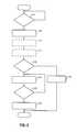
- FIG. 3is a flowchart depicting an example method of performing a cold start of an SIDI engine according to the present disclosure.
- a spark ignition direct injection (SIDI) enginecombusts air and fuel to generate drive torque for a vehicle.
- the fuelis injected directly into cylinders of SIDI engines.
- the fuelmay be gasoline, a mixture of gasoline and ethanol, or another suitable type of fuel.
- Engines that can combust gasoline, ethanol, and a mixture of gasoline and ethanolcan be referred to as flex fuel engines.
- a control moduleselectively starts an SIDI engine in response to user actuation of an ignition input, such as an ignition key or button, or initiation of an auto-start event.
- the control modulecontrols various operating parameters during startup of the SIDI engine and while the SIDI engine is ON (running) after startup. For example, the control module controls opening of a throttle valve, fuel injection amount and timing, spark timing, and other suitable operating parameters during startup of the SIDI engine and while the SIDI engine is ON after startup.
- the control modulealso selectively shuts down the SIDI engine in response to user actuation of an ignition input or initiation of an auto-stop event.
- the flash point temperature of a fuelmay refer to a minimum temperature at which the fuel can vaporize to form an ignitable mixture in air. At temperatures that are less than the flash point temperature of the fuel that is directly injected into the SIDI engine, the fuel may be unable to vaporize during startup, and the SIDI engine may be unable to start.
- One or more auxiliary devicescan be added to facilitate startup of the SIDI engine at temperatures that are less than the flash point temperature of the fuel.
- a block heater and/or a fuel rail heater or a fuel injector heatermay be added to warm the fuel. Warming the fuel may enable the fuel to vaporize sufficiently to allow startup of the SIDI engine at temperatures that are less than the flash point temperature of the fuel.
- a separate gasoline tank and a gasoline injectorcan be added for use during startup of engines using a fuel having a high flash point temperature, such as Ethanol. Adding one or more auxiliary devices, however, increases vehicle cost.
- the control moduleselectively controls the throttle valve, fueling, and spark during startup of the SIDI engine as to enable startup of the SIDI engine.
- the engine systemincludes an engine 102 that combusts an air/fuel mixture to produce drive torque for a vehicle. Air is drawn into an intake manifold 104 through a throttle valve 106 . The throttle valve 106 regulates air flow into the intake manifold 104 . Air within the intake manifold 104 is drawn into cylinders of the engine 102 , such as cylinder 108 .
- One or more fuel injectorsinject fuel that mixes with air to form an air/fuel mixture.
- one fuel injectormay be provided for each cylinder of the engine 102 .
- the fuel injectorsinject fuel directly into the cylinders.
- Fuel injectionmay be controlled based on a desired air/fuel mixture for combustion, such as a stoichiometric air/fuel mixture.
- a fuel systemprovides fuel to the fuel injectors. The fuel system is discussed further below.
- An intake valve 112opens to allow air into the cylinder 108 .
- a piston(not shown) compresses the air/fuel mixture within the cylinder 108 .
- a spark plug 114initiates combustion of the air/fuel mixture within the cylinder 108 .
- One spark plugmay be provided for each cylinder of the engine 102 . Combustion of the air/fuel mixture applies force to the piston, and the piston drives rotation of a crankshaft (not shown).
- the engine 102outputs torque via the crankshaft.
- a flywheel 120is coupled to the crankshaft and rotates with the crankshaft.
- Torque output by the engine 102is selectively transferred to a transmission 122 via a torque transfer device 124 .
- the torque transfer device 124selectively couples/decouples the transmission 122 to/from the engine 102 .
- the transmission 122may include, for example, a manual transmission, an automatic transmission, a semi-automatic transmission, an auto-manual transmission, or another suitable type of transmission.
- the torque transfer device 124may include, for example, a torque converter and/or one or more clutches.
- Exhaust produced by combustion of the air/fuel mixtureis expelled from the cylinder 108 via an exhaust valve 126 .
- the exhaustis expelled from the cylinders to an exhaust system 128 .
- the exhaust system 128may treat the exhaust before the exhaust is expelled from the exhaust system 128 .
- one intake and exhaust valveare shown and described as being associated with the cylinder 108 , more than one intake and/or exhaust valve may be associated with each cylinder of the engine 102 .
- An engine control module (ECM) 130controls various engine actuators.
- the engine actuatorsmay include, for example, a throttle actuator module 132 , a fuel actuator module 134 , and a spark actuator module 136 .
- the engine system 100may also include other engine actuators, and the ECM 130 may control the other engine actuators.
- Each engine actuatorcontrols an operating parameter based on a signal from the ECM 130 .
- the throttle actuator module 132may control opening of the throttle valve 106
- the fuel actuator module 134may control fuel injection amount and timing
- the spark actuator module 136may control spark timing.
- the ECM 130may control the engine actuators based on, for example, driver inputs and inputs from various vehicle systems.
- vehicle systemsmay include, for example, a transmission system, a hybrid control system, a stability control system, a chassis control system, and other suitable vehicle systems.
- a driver input module 140may provide the driver inputs to the ECM 130 .
- the driver inputs provided to the ECM 130may include, for example, an accelerator pedal position (APP), a brake pedal position (BPP), cruise control inputs, and vehicle operation commands.
- An APP sensor 142measures position of an accelerator pedal (not shown) and generates the APP based on the position of the accelerator pedal.
- a BPP sensor 144monitors actuation of a brake pedal (not shown) and generates the BPP based on a position of the brake pedal.
- a cruise control system 146provides the cruise control inputs, such as a desired vehicle speed, based on inputs to the cruise control system 146 .
- the vehicle operation commandsmay include, for example, vehicle startup commands and vehicle shutdown commands.
- the vehicle operation commandsmay be input by a user via actuation of one or more ignition system inputs 148 .
- a usermay input the vehicle operation commands by actuating an ignition key, one or more buttons/switches, and/or one or more other suitable ignition system inputs.
- An engine speed sensor 152measures rotational speed of the engine 102 and generates an engine speed based on the speed. For example only, the engine speed sensor 152 may generate the engine speed based on rotation of the crankshaft in revolutions per minute (rpm).
- a coolant temperature sensor 154measures a temperature of engine coolant and generates an engine coolant temperature (ECT) based on the temperature of the engine coolant.
- the ECM 130may also receive operating parameters measured by other sensors 156 , such as oxygen in the exhaust, intake air temperature (IAT), mass air flowrate (MAF), oil temperature, manifold absolute pressure (MAP), and/or other suitable parameters.
- ethanol contentmay be measured using a sensor.
- the ECM 130selectively shuts down the engine 102 when a user inputs a vehicle shutdown command.
- the ECM 130may disable the injection of fuel, disable the provision of spark, and perform other shutdown operations to shut down the engine 102 in response to receipt of a vehicle shutdown command.
- the ECM 130selectively starts the engine 102 .
- the ECM 130starts the engine 102 in response to receipt of a vehicle startup command or initiation of an auto-start event.
- the ECM 130engages a starter motor 160 with the engine 102 to initiate engine startup.
- the starter motor 160may engage the flywheel 120 or other suitable component(s) that drive rotation of the crankshaft.
- a starter motor actuator 162such as a solenoid, selectively engages the starter motor 160 with the engine 102 .
- a starter actuator module 164controls the starter motor actuator 162 and the starter motor 160 based on signals from the ECM 130 . For example only, the ECM 130 may command engagement of the starter motor 160 when the vehicle startup command is received.
- the starter actuator module 164selectively applies current to the starter motor 160 when the starter motor 160 is engaged with the engine 102 .
- the application of current to the starter motor 160drives the starter motor 160 , and the starter motor 160 drives the crankshaft.
- the starter motor 160may be disengaged from the engine 102 , and the flow of current to the starter motor 160 may be discontinued.
- the engine 102may be deemed running, for example, when the engine speed exceeds a predetermined speed, such as approximately 700 rpm or another suitable speed.
- the period between when the starter motor 160 is engaged with the engine 102 for starting the engine and when the engine 102 is deemed runningmay be referred to as engine cranking.
- the current provided to the starter motor 160may be provided by, for example, a battery 170 . While only the battery 170 is shown, the battery 170 may include one or more individual batteries that are connected together or one or more other batteries may be provided.
- the engine system 100may include one or more electric motors, such as electric motor (EM) 172 .
- the EM 172may selectively draw electrical power, for example, to supplement the torque output of the engine 102 .
- the EM 172may also selectively function as a generator and selectively apply a braking torque to the engine 102 to generate electrical power.
- Generated electrical powermay be used, for example, to charge the battery 170 , to provide electrical power to one or more other EMs (not shown), to provide electrical power to other vehicle systems, and/or for other suitable uses.
- the fuel systemsupplies fuel to the fuel injectors.
- the fuel systemmay include a fuel tank 174 , a low pressure fuel pump 176 , a high pressure fuel pump 178 , a fuel rail 180 , a pressure relief valve 182 , and/or one or more other suitable components.
- the low pressure fuel pump 176draws fuel from the fuel tank 174 and provides fuel at low pressures to the high pressure fuel pump 178 .
- the low pressures provided by the low pressure fuel pump 176are expressed relative to pressurization provided by the high pressure fuel pump 178 .
- the low pressure fuel pump 176is an electrically driven fuel pump, and a pump actuator module 184 may control the application of power to the low pressure fuel pump 176 based on signals from the ECM 130 .
- the ECM 130may command application of power to the low pressure fuel pump 176 when or before a vehicle startup command is input.
- the high pressure fuel pump 178pressurizes the fuel received from the low pressure fuel pump 176 within the fuel rail 180 .
- the high pressure fuel pump 178is engine driven, such as by the crankshaft or by a camshaft.
- the high pressure fuel pump 178may pump fuel into the fuel rail 180 , for example, once, twice, or more per revolution of the crankshaft.
- the fuel injectorsinject fuel from the fuel rail 180 into the cylinders.
- the high pressure fuel pump 178pressurizes the fuel within the fuel rail 180 to pressures that are greater than pressure within the cylinder during fuel injection.
- the pressure relief valve 182releases fuel back to the fuel tank 174 .
- the engine 102may be referred to as a spark ignition direct injection (SIDI) engine.
- Flex fuel SIDI enginescan combust gasoline, a blend of gasoline and ethanol, or ethanol.
- An ethanol fuelmay be referred to using the prefix E and an integer corresponding to an amount of ethanol in the blend by volume.
- E85may refer to a blend of gasoline and ethanol that includes 85 percent ethanol by volume
- E50may refer to a blend of gasoline and ethanol that includes up to 50 percent ethanol by volume
- Ethanolmay be referred to as E100
- gasolinemay be referred to as E0.
- Other types of fuels that may be combusted by SIDI enginesinclude methanol, other alcohol based fuels, liquefied petroleum gas (LPG), propane, butane, etc.
- LPGliquefied petroleum gas
- Flash point temperature of a fuelmay refer to a minimum temperature at which the fuel can vaporize to form an ignitable mixture in air.
- E100may have a flash point temperature of approximately 18° C. Fuels having a flash point temperature that is greater than the predetermined minimum temperature may be unable to vaporize and/or combust when the engine 102 is started at or even above the predetermined minimum temperature.
- One or more auxiliary devicescould be added to the vehicle to enable startup of the engine 102 at temperatures that are less than the flash point temperature of the fuel within the fuel tank 174 .
- a gasoline injector and a separate gasoline fuel tankcan be added, and the gasoline can be injected during engine cranking to enable startup of the engine 102 .
- an engine block heater and/or one or more other electrical heaterssuch as a fuel rail heater or fuel injector heaters, can be added to warm the fuel to enable startup of the engine 102 .
- the addition of one or more of these auxiliary, startup enabling devicesalso increases vehicle cost.
- zero auxiliary devicese.g, engine block heater, separate gasoline injector, separate gasoline fuel tank, and/or one or more electrical heaters
- a startup control module 190selectively closes the throttle valve 106 and controls fueling during engine cranking to enable vaporization of the fuel and to start the engine 102 .
- a starter control module 208commands the starter actuator module 164 to engage the starter motor 160 with the engine 102 and apply power to the starter motor 160 .
- the vehicle startup command 204may be input by the driver, for example, by actuating one or more ignition inputs.
- the starter actuator module 164engages the starter motor 160 with the engine 102 and applies power to the starter motor 160 in response to the command.
- the starter motor 160drives rotation of the crankshaft.
- Poweris also applied to the low pressure fuel pump 176 during engine cranking. Power may be applied to the low pressure fuel pump 176 beginning before power is applied to the starter motor 160 .
- the low pressure fuel pump 176may be controlled during engine cranking and while the engine 102 is running based on providing fuel to the high pressure fuel pump 178 at a predetermined low pressure.
- the high pressure fuel pump 178increases the pressure of the fuel within the fuel rail 180 as the starter motor 160 drives the crankshaft.
- a throttle control module 212controls opening of the throttle valve 106 .
- the throttle control module 212may set a desired area 216 for the throttle valve 106 , and the throttle actuator module 132 may actuate the throttle valve 106 based on the desired area 216 .
- a fuel control module 220controls amount and timing of fuel injection.
- the fuel control module 220may set desired fueling parameters 224 (e.g., desired amount, desired timing, desired number of pulses, etc.), and the fuel actuator module 134 may control the fuel injectors based on the desired fueling parameters 224 .
- the throttle control module 212may de-energize the throttle valve 106 .
- the throttle valve 106When de-energized, the throttle valve 106 may be biased (mechanically) to a predetermined open position. The throttle valve 106 may be biased against one or more stops. When in the predetermined open position, a predetermined open area is achieved, such as approximately 80 percent open.
- the opening of the throttle valve 106should be at approximately the predetermined open position at the time when the vehicle startup command 204 is received. Additionally, pressure within the intake manifold 104 should be approximately equal to ambient air pressure when the vehicle startup command 204 is received. As stated above, the fuel within the fuel tank 174 may be unable to vaporize and the engine 102 may be unable to start at temperatures that are less than the flash point temperature of the fuel.
- a mode setting module 228sets a mode 232 of operation for the engine 102 .
- the throttle control module 212 and the fuel control module 220control the throttle valve 112 and fuel injection, respectively, based on the mode 232 .
- Control modules of one or more other engine actuatorsmay also control the other engine actuators based on the mode 232 .
- the mode setting module 228may set the mode 232 to a coldstart mode in response to the receipt of the vehicle startup command 204 and a determination that a temperature is less than a predetermined temperature. For example, the mode setting module 228 may set the mode 232 to the coldstart mode when an ECT (engine coolant temperature) 236 is less than the predetermined temperature.
- the predetermined temperatureis less than the flash point temperature of the fuel within the fuel tank 174 .
- the predetermined temperaturemay be a predetermined value that is less than or equal to 18 degrees Celsius (° C.) or another suitable temperature below which the fuel within the fuel tank 174 may be unable to vaporize during engine cranking.
- the mode setting module 228may set the mode 232 to a start mode for a normal engine startup.
- a parameter determination module 240may be included.
- the parameter determination module 240may determine a characteristic 244 of the fuel within the fuel tank 174 .
- the parameter determination module 240may determine a percentage of ethanol in the fuel within the fuel tank 174 .
- the parameter determination module 240may determine the characteristic 244 of the fuel within the fuel tank 174 , for example, based on measurements provided by a fuel sensor, cylinder pressures, or other suitable parameters.
- the mode setting module 228may set the predetermined temperature (used for determining whether to set the mode 232 to the coldstart mode) based on the characteristic 244 .
- the mode setting module 228may set the predetermined temperature using a function or a mapping (e.g., lookup table) that relates the characteristic 244 of the fuel within the fuel tank 174 to the predetermined temperature.
- the throttle control module 212 and the fuel control module 220control the throttle valve 112 and fuel injection for a cold start of the engine 102 . More specifically, when the mode 232 is set to the coldstart mode, the throttle control module 212 selectively closes the throttle valve 112 relative to the predetermined open position during engine cranking. Closing the throttle valve 112 increases the vacuum (i.e., lowers the pressure) within the intake manifold 104 and the cylinders. The lower pressure within the intake manifold 104 may provide better conditions for vaporization when the fuel is injected into a cylinder.
- the throttle control module 212may close the throttle valve 112 to a predetermined fully closed position during engine cranking when the mode 232 is set to the cold start mode.
- a predetermined fully closed areais achieved, such as approximately zero percent open.
- the throttle control module 212may close the throttle valve 112 based on adjusting the pressure within the intake manifold 104 to a target pressure when the mode 232 is set to the cold start mode.
- the target pressuremay be a predetermined pressure that is less than ambient air pressure.
- the throttle control module 212may control the throttle valve 112 in closed-loop based on measurements provided by a MAP sensor and the target pressure.
- the fuel control module 220When the mode 232 is set to the cold start mode, the fuel control module 220 generally provides rich fueling for combustion events. However, the fuel control module 220 may disable fuel injection for one or more combustion events when the mode 232 is set to the coldstart mode. The fuel control module 220 may disable fuel injection, for example, for one or more of the combustion events that would occur soonest after the starter motor 160 begins cranking the engine 102 . Disabling fuel injection for a combustion event allows the high pressure fuel pump 178 to increase the pressure within the fuel rail 180 . The pressure within the fuel rail 180 being higher may increase vaporization of fuel injected into a cylinder and increase temperature of the walls and body of the cylinder.
- Injection of fuel for a given combustion eventmay be accomplished using one or more individual injections of fuel.
- the fuel control module 220may command one injection of fuel for a combustion event of a cylinder be performed while the intake valve(s) of the cylinder is open for the combustion event.
- the lower pressure within the intake manifold 104 that is attributable to the closing of the throttle valve 112may enable the fuel that is injected while the intake valve(s) is open to vaporize to a greater extent.
- the fuel control module 220may also command one or more other fuel injections for the combustion event be performed after the intake valve of the cylinder is closed for the combustion event.
- the fuel and air charge temperature increase during the cylinder compression eventcan therefore occur at a lower pressure due to the lower intake manifold pressure and thus enable the fuel to vaporize to a greater extent.
- a spark control module 248sets a desired spark timing 252 , and the spark actuator module 136 generates spark based on the desired spark timing 252 .
- the spark control module 248may disable spark for one or more combustion events. Disabling spark for a combustion event may enable a charge of air and fuel to warm within a cylinder. This may enable more fuel of the charge to vaporize when it is combusted during a later combustion event.
- the mode setting module 228may transition the mode 232 from the coldstart mode (or the start mode) to an engine running mode when the engine is running after a startup.
- the mode setting module 228may transition the mode 232 to the engine running mode, for example, when an engine speed becomes greater than a predetermined speed, such as approximately 700 rpm or another suitable speed.
- the throttle control module 212 , the fuel control module 220 , and the spark control module 248may transition to normal control of the throttle valve 112 , fueling, and spark timing in response to a transition in the mode 232 to the engine running mode.
- Controlmay begin with 304 at a time when the engine 102 is off pursuant to a vehicle shutdown request.
- controldetermines whether a user has input a vehicle startup command. If true, control continues with 308 . If false, control remains at 304 and waits for a user to input a vehicle startup command.
- a usermay input a vehicle startup command by actuating an ignition switch, an ignition button, etc.
- controlengages the starter motor 160 with the engine 102 and applies power to the starter motor 160 .
- the starter motor 160drives rotation of the crankshaft of the engine 102 .
- the low pressure fuel pump 176may be activated to begin pumping fuel to the high pressure fuel pump 178 before the starter motor 160 begins driving the crankshaft.
- the high pressure fuel pump 178pumps fuel into the fuel rail 180 as the starter motor 160 drives the crankshaft.
- Controlmay obtain a characteristic of the fuel within the fuel tank 174 at 312 .
- the characteristic of the fuelmay be, for example, an ethanol concentration of the fuel, a flash point temperature of the fuel, or another suitable characteristic of the fuel.
- controlmay set the predetermined temperature used in determining whether the startup of the engine 102 is a cold start based on the characteristic of the fuel.
- controlmay determine whether the ECT 236 is less than the predetermined temperature. If true, control may continue with 324 and perform a coldstart of the engine 102 . If false, control may perform a normal startup of the engine 102 at 322 , and control may end.
- the predetermined temperatureis less than the flash point temperature of the fuel and may be less than or equal to +18° C.
- controlregulates the throttle valve 112 , fuel injection, and spark timing for the coldstart of the engine 102 . More specifically, control closes the throttle valve 112 from the predetermined open position during engine cranking. Control may close the throttle valve 112 to the predetermined fully closed position or regulate the throttle valve 112 based on achieving the target MAP. Control may command an injection of fuel for a combustion event of a cylinder while the intake valve is open for the cylinder. Control may additionally or alternatively disable fuel injections for one or more combustion events during engine cranking. Control may disable spark for one or more combustion events during engine cranking. A combination of one or more of the above may enable fuel injected into the cylinders to vaporize and allow the engine 102 to start. Control may also alter the injected quantity of fuel on a cylinder event basis.
- controlmay determine whether the engine 102 is running. If true, control may transition to controlling the throttle valve 112 , fuel injection, and spark timing in a normal operation mode at 332 , and control may end. If false, control may return to 324 and continue controlling the throttle valve 112 , fuel injection, and spark timing for the coldstart of the engine 102 .
- the engine 102may be deemed running, for example, when the engine speed is greater than the predetermined speed.
- modulemay refer to, be part of, or include an Application Specific Integrated Circuit (ASIC); an electronic circuit; a combinational logic circuit; a field programmable gate array (FPGA); a processor (shared, dedicated, or group) that executes code; other suitable hardware components that provide the described functionality; or a combination of some or all of the above, such as in a system-on-chip.
- ASICApplication Specific Integrated Circuit
- FPGAfield programmable gate array
- the term modulemay include memory (shared, dedicated, or group) that stores code executed by the processor.
- codemay include software, firmware, and/or microcode, and may refer to programs, routines, functions, classes, and/or objects.
- sharedmeans that some or all code from multiple modules may be executed using a single (shared) processor. In addition, some or all code from multiple modules may be stored by a single (shared) memory.
- groupmeans that some or all code from a single module may be executed using a group of processors. In addition, some or all code from a single module may be stored using a group of memories.
- the apparatuses and methods described hereinmay be implemented by one or more computer programs executed by one or more processors.
- the computer programsinclude processor-executable instructions that are stored on a non-transitory tangible computer readable medium.
- the computer programsmay also include stored data.
- Non-limiting examples of the non-transitory tangible computer readable mediumare nonvolatile memory, magnetic storage, and optical storage.
Landscapes
- Engineering & Computer Science (AREA)
- Chemical & Material Sciences (AREA)
- Combustion & Propulsion (AREA)
- Mechanical Engineering (AREA)
- General Engineering & Computer Science (AREA)
- Oil, Petroleum & Natural Gas (AREA)
- Electrical Control Of Air Or Fuel Supplied To Internal-Combustion Engine (AREA)
Abstract
Description
Claims (20)
Priority Applications (2)
| Application Number | Priority Date | Filing Date | Title |
|---|---|---|---|
| US13/464,164US8775054B2 (en) | 2012-05-04 | 2012-05-04 | Cold start engine control systems and methods |
| BRBR102013008732-7ABR102013008732A2 (en) | 2012-05-04 | 2013-04-10 | Cold start control method for a vehicle |
Applications Claiming Priority (1)
| Application Number | Priority Date | Filing Date | Title |
|---|---|---|---|
| US13/464,164US8775054B2 (en) | 2012-05-04 | 2012-05-04 | Cold start engine control systems and methods |
Publications (2)
| Publication Number | Publication Date |
|---|---|
| US20130297182A1 US20130297182A1 (en) | 2013-11-07 |
| US8775054B2true US8775054B2 (en) | 2014-07-08 |
Family
ID=49513231
Family Applications (1)
| Application Number | Title | Priority Date | Filing Date |
|---|---|---|---|
| US13/464,164Active2033-01-15US8775054B2 (en) | 2012-05-04 | 2012-05-04 | Cold start engine control systems and methods |
Country Status (2)
| Country | Link |
|---|---|
| US (1) | US8775054B2 (en) |
| BR (1) | BR102013008732A2 (en) |
Cited By (4)
| Publication number | Priority date | Publication date | Assignee | Title |
|---|---|---|---|---|
| US20150128907A1 (en)* | 2013-11-08 | 2015-05-14 | Achates Power, Inc. | Cold-Start Strategies for Opposed-Piston Engines |
| US10100767B2 (en) | 2015-06-08 | 2018-10-16 | Ford Global Technologies, Llc | Method and system for engine cold-start control |
| US10156219B1 (en) | 2017-11-27 | 2018-12-18 | GM Global Technology Operations LLC | Method for controlling spark timing in a cold start condition for an engine in a vehicle propulsion system and controller for executing the method |
| RU2683292C1 (en)* | 2015-08-04 | 2019-03-27 | Форд Глобал Текнолоджиз, Ллк | Engine cold-start control |
Families Citing this family (11)
| Publication number | Priority date | Publication date | Assignee | Title |
|---|---|---|---|---|
| US10180115B2 (en) | 2010-04-27 | 2019-01-15 | Achates Power, Inc. | Piston crown bowls defining combustion chamber constructions in opposed-piston engines |
| EP2817495B1 (en) | 2012-02-21 | 2020-04-15 | Achates Power, Inc. | Exhaust management strategies for opposed-piston, two-stroke engines |
| US9567934B2 (en)* | 2013-06-19 | 2017-02-14 | Enviro Fuel Technology, Lp | Controllers and methods for a fuel injected internal combustion engine |
| US9211797B2 (en) | 2013-11-07 | 2015-12-15 | Achates Power, Inc. | Combustion chamber construction with dual mixing regions for opposed-piston engines |
| JP6252345B2 (en)* | 2014-05-09 | 2017-12-27 | トヨタ自動車株式会社 | Control device for internal combustion engine |
| WO2016114782A1 (en)* | 2015-01-15 | 2016-07-21 | Truax Ryan | Alternative fuel module for spark ignition fuel injected engines |
| ITUB20152628A1 (en)* | 2015-07-30 | 2017-02-05 | Magneti Marelli Spa | METHOD FOR COLD START-UP OF AN INTERNAL COMBUSTION ENGINE POWERED BY A FUEL MIXTURE CONTAINING ETHANOL |
| DE102016206291B3 (en)* | 2016-04-14 | 2017-08-24 | Continental Automotive Gmbh | Method for starting a natural gas-powered internal combustion engine |
| DE102016215116B3 (en)* | 2016-08-12 | 2017-06-08 | Continental Automotive Gmbh | Method and device for starting an internal combustion engine with high alcohol content in the fuel |
| KR101926927B1 (en)* | 2016-11-14 | 2018-12-07 | 현대자동차주식회사 | Engine start control method for flexible fuel vehicle |
| CN106585610B (en)* | 2016-11-21 | 2019-02-26 | 浙江吉利控股集团有限公司 | A power source cold start control system and method |
Citations (48)
| Publication number | Priority date | Publication date | Assignee | Title |
|---|---|---|---|---|
| US3999525A (en) | 1970-11-25 | 1976-12-28 | Robert Bosch G.M.B.H. | Apparatus for the cold starting and warming run of spark plug-ignited internal combustion engines |
| US4219154A (en) | 1978-07-10 | 1980-08-26 | The Bendix Corporation | Electronically controlled, solenoid operated fuel injection system |
| US4222358A (en) | 1977-12-10 | 1980-09-16 | Volkswagenwerk Aktiengesellschaft | Fuel injection system |
| US4271807A (en) | 1978-01-25 | 1981-06-09 | Robert Bosch Gmbh | Pump/nozzle for internal combustion engines |
| US4375799A (en)* | 1980-04-16 | 1983-03-08 | Swanson Clifford S | Fuel vaporization system |
| US4437443A (en) | 1980-12-20 | 1984-03-20 | Volkswagenwerk Ag | Fuel injection device |
| US4449507A (en) | 1980-12-17 | 1984-05-22 | The Bendix Corporation | Dual pressure metering for distributor pumps |
| US4599861A (en) | 1985-05-13 | 1986-07-15 | Beaumont Richard W | Internal combustion hydraulic engine |
| US4838231A (en) | 1986-09-25 | 1989-06-13 | Ganser-Hydromag | Electronically controlled fuel injection system |
| US4886032A (en) | 1988-11-22 | 1989-12-12 | Chrysler Motors Corporation | Fuel injector heating method |
| US5201341A (en) | 1991-03-19 | 1993-04-13 | Nippon Soken, Inc. | Electromagnetic type fluid flow control valve |
| US5322046A (en) | 1992-10-08 | 1994-06-21 | Microfuels, Inc. | Electronic fuel injector control for rotary vacuum fuel conversion device |
| US5355856A (en) | 1992-07-23 | 1994-10-18 | Paul Marius A | High pressure differential fuel injector |
| US5485957A (en) | 1994-08-05 | 1996-01-23 | Sturman; Oded E. | Fuel injector with an internal pump |
| US5501197A (en) | 1993-06-15 | 1996-03-26 | Perkins Limited | Fuel injection apparatus |
| US5622152A (en) | 1994-07-08 | 1997-04-22 | Mitsubishi Jidosha Kogyo Kabushiki Kaisha | Pressure storage fuel injection system |
| GB2307513A (en) | 1995-11-25 | 1997-05-28 | Ford Motor Co | Solenoid fuel injector with heating |
| US5709196A (en) | 1996-09-24 | 1998-01-20 | Caterpillar Inc. | Fuel control system for an internal combustion engine using a low cetane quality fuel |
| US5915626A (en) | 1996-07-23 | 1999-06-29 | Robert Bosch Gmbh | Fuel injector |
| US6078861A (en) | 1998-10-14 | 2000-06-20 | Ford Global Technologies, Inc. | Onboard diagnostic monitoring for flexible fuel vehicles |
| US6113361A (en) | 1999-02-02 | 2000-09-05 | Stanadyne Automotive Corp. | Intensified high-pressure common-rail supply pump |
| US20010050068A1 (en) | 1992-07-27 | 2001-12-13 | Kruse Douglas C. | Internal combustion engine with limited temperature cycle |
| US6499448B2 (en) | 2000-05-17 | 2002-12-31 | Robert Bosch Gmbh | Apparatus for direct gasoline injection in a piston engine |
| DE10136049A1 (en) | 2001-07-25 | 2003-02-20 | Bosch Gmbh Robert | Fuel heater for internal combustion engine fuel injection system, supplies current pulses tailored to avoid fuel injector actuation while causing resistance heating of solenoids |
| US6637408B2 (en) | 1999-02-17 | 2003-10-28 | Stanadyne Corporation | Common rail fuel supply system with high pressure accumulator |
| US6776138B2 (en) | 2000-12-01 | 2004-08-17 | Robert Bosch Gmbh | Fuel injection device |
| US6786205B2 (en) | 2003-01-08 | 2004-09-07 | The United States Of America As Represented By The Environmental Production Agency | Hydraulically intensified high pressure fuel system for common rail application |
| US6883498B2 (en) | 2001-05-11 | 2005-04-26 | Robert Bosch Gmbh | Pressure booster for a fuel injection system |
| US6899088B2 (en) | 2000-09-20 | 2005-05-31 | Stanadyne Corporation | Flow intensifier for cold starting gasoline direct injection engine |
| US20050116058A1 (en) | 2002-06-29 | 2005-06-02 | Hans-Christoph Magel | Control of a pressure exchanger by displacement of an injection valve member |
| US20060042565A1 (en) | 2004-08-26 | 2006-03-02 | Eaton Corporation | Integrated fuel injection system for on-board fuel reformer |
| US7155334B1 (en) | 2005-09-29 | 2006-12-26 | Honeywell International Inc. | Use of sensors in a state observer for a diesel engine |
| US7278398B2 (en) | 2003-08-01 | 2007-10-09 | Robert Bosch Gmbh | Control valve for a fuel injector that contains a pressure intensifier |
| US7316361B2 (en) | 2003-07-30 | 2008-01-08 | Robert Bosch Gmbh | Control valve with pressure compensation for a fuel injector comprising a pressure intensifier |
| US7320311B2 (en) | 2004-04-30 | 2008-01-22 | Toyota Jidosha Kabushiki Kaisha | Pressure boosting common rail fuel injection apparatus and fuel injection control method therefor |
| CN101122263A (en) | 2006-08-11 | 2008-02-13 | 福特环球技术公司 | Direct injection alcohol engine with variable injection timing |
| US7404393B2 (en) | 2002-07-04 | 2008-07-29 | Delphi Technologies, Inc. | Fuel injection system |
| US7406947B2 (en) | 2005-11-30 | 2008-08-05 | Ford Global Technologies, Llc | System and method for tip-in knock compensation |
| US20080265054A1 (en) | 2005-06-29 | 2008-10-30 | Christoph Buehler | Injector With A Pressure Intensifier That Can Be Switched On |
| US7451742B2 (en) | 2007-10-29 | 2008-11-18 | Caterpillar Inc. | Engine having common rail intensifier and method |
| US7461795B2 (en) | 2002-10-25 | 2008-12-09 | Robert Bosch Gmbh | Fuel injection system for internal combustion engines |
| US20090120396A1 (en)* | 2007-11-08 | 2009-05-14 | Delphi Technologies, Inc. | Method for cold starting of ethanol-fueled engines |
| US20090153149A1 (en) | 2007-12-12 | 2009-06-18 | Norberto Hernandez | Obstructionless inline flex fuel sensor |
| US20090206184A1 (en) | 2008-02-16 | 2009-08-20 | Mi Yan | Fuel injector with real-time feedback control |
| US7578283B1 (en) | 2008-06-30 | 2009-08-25 | Caterpillar Inc. | System for selectively increasing fuel pressure in a fuel injection system |
| US20090234561A1 (en) | 2008-03-11 | 2009-09-17 | Gm Global Technology Operations, Inc. | Method to enable direct injection of e85 in flex fuel vehicles by adjusting the start of injection |
| US7832374B2 (en) | 2008-10-21 | 2010-11-16 | Gm Global Technology Operations, Inc. | Fuel pressure amplifier |
| US7849839B2 (en) | 2006-09-01 | 2010-12-14 | Gm Global Technology Operations, Inc. | Pre-heating fuel for cold start |
- 2012
- 2012-05-04USUS13/464,164patent/US8775054B2/enactiveActive
- 2013
- 2013-04-10BRBRBR102013008732-7Apatent/BR102013008732A2/ennot_activeIP Right Cessation
Patent Citations (48)
| Publication number | Priority date | Publication date | Assignee | Title |
|---|---|---|---|---|
| US3999525A (en) | 1970-11-25 | 1976-12-28 | Robert Bosch G.M.B.H. | Apparatus for the cold starting and warming run of spark plug-ignited internal combustion engines |
| US4222358A (en) | 1977-12-10 | 1980-09-16 | Volkswagenwerk Aktiengesellschaft | Fuel injection system |
| US4271807A (en) | 1978-01-25 | 1981-06-09 | Robert Bosch Gmbh | Pump/nozzle for internal combustion engines |
| US4219154A (en) | 1978-07-10 | 1980-08-26 | The Bendix Corporation | Electronically controlled, solenoid operated fuel injection system |
| US4375799A (en)* | 1980-04-16 | 1983-03-08 | Swanson Clifford S | Fuel vaporization system |
| US4449507A (en) | 1980-12-17 | 1984-05-22 | The Bendix Corporation | Dual pressure metering for distributor pumps |
| US4437443A (en) | 1980-12-20 | 1984-03-20 | Volkswagenwerk Ag | Fuel injection device |
| US4599861A (en) | 1985-05-13 | 1986-07-15 | Beaumont Richard W | Internal combustion hydraulic engine |
| US4838231A (en) | 1986-09-25 | 1989-06-13 | Ganser-Hydromag | Electronically controlled fuel injection system |
| US4886032A (en) | 1988-11-22 | 1989-12-12 | Chrysler Motors Corporation | Fuel injector heating method |
| US5201341A (en) | 1991-03-19 | 1993-04-13 | Nippon Soken, Inc. | Electromagnetic type fluid flow control valve |
| US5355856A (en) | 1992-07-23 | 1994-10-18 | Paul Marius A | High pressure differential fuel injector |
| US20010050068A1 (en) | 1992-07-27 | 2001-12-13 | Kruse Douglas C. | Internal combustion engine with limited temperature cycle |
| US5322046A (en) | 1992-10-08 | 1994-06-21 | Microfuels, Inc. | Electronic fuel injector control for rotary vacuum fuel conversion device |
| US5501197A (en) | 1993-06-15 | 1996-03-26 | Perkins Limited | Fuel injection apparatus |
| US5622152A (en) | 1994-07-08 | 1997-04-22 | Mitsubishi Jidosha Kogyo Kabushiki Kaisha | Pressure storage fuel injection system |
| US5485957A (en) | 1994-08-05 | 1996-01-23 | Sturman; Oded E. | Fuel injector with an internal pump |
| GB2307513A (en) | 1995-11-25 | 1997-05-28 | Ford Motor Co | Solenoid fuel injector with heating |
| US5915626A (en) | 1996-07-23 | 1999-06-29 | Robert Bosch Gmbh | Fuel injector |
| US5709196A (en) | 1996-09-24 | 1998-01-20 | Caterpillar Inc. | Fuel control system for an internal combustion engine using a low cetane quality fuel |
| US6078861A (en) | 1998-10-14 | 2000-06-20 | Ford Global Technologies, Inc. | Onboard diagnostic monitoring for flexible fuel vehicles |
| US6113361A (en) | 1999-02-02 | 2000-09-05 | Stanadyne Automotive Corp. | Intensified high-pressure common-rail supply pump |
| US6637408B2 (en) | 1999-02-17 | 2003-10-28 | Stanadyne Corporation | Common rail fuel supply system with high pressure accumulator |
| US6499448B2 (en) | 2000-05-17 | 2002-12-31 | Robert Bosch Gmbh | Apparatus for direct gasoline injection in a piston engine |
| US6899088B2 (en) | 2000-09-20 | 2005-05-31 | Stanadyne Corporation | Flow intensifier for cold starting gasoline direct injection engine |
| US6776138B2 (en) | 2000-12-01 | 2004-08-17 | Robert Bosch Gmbh | Fuel injection device |
| US6883498B2 (en) | 2001-05-11 | 2005-04-26 | Robert Bosch Gmbh | Pressure booster for a fuel injection system |
| DE10136049A1 (en) | 2001-07-25 | 2003-02-20 | Bosch Gmbh Robert | Fuel heater for internal combustion engine fuel injection system, supplies current pulses tailored to avoid fuel injector actuation while causing resistance heating of solenoids |
| US20050116058A1 (en) | 2002-06-29 | 2005-06-02 | Hans-Christoph Magel | Control of a pressure exchanger by displacement of an injection valve member |
| US7404393B2 (en) | 2002-07-04 | 2008-07-29 | Delphi Technologies, Inc. | Fuel injection system |
| US7461795B2 (en) | 2002-10-25 | 2008-12-09 | Robert Bosch Gmbh | Fuel injection system for internal combustion engines |
| US6786205B2 (en) | 2003-01-08 | 2004-09-07 | The United States Of America As Represented By The Environmental Production Agency | Hydraulically intensified high pressure fuel system for common rail application |
| US7316361B2 (en) | 2003-07-30 | 2008-01-08 | Robert Bosch Gmbh | Control valve with pressure compensation for a fuel injector comprising a pressure intensifier |
| US7278398B2 (en) | 2003-08-01 | 2007-10-09 | Robert Bosch Gmbh | Control valve for a fuel injector that contains a pressure intensifier |
| US7320311B2 (en) | 2004-04-30 | 2008-01-22 | Toyota Jidosha Kabushiki Kaisha | Pressure boosting common rail fuel injection apparatus and fuel injection control method therefor |
| US20060042565A1 (en) | 2004-08-26 | 2006-03-02 | Eaton Corporation | Integrated fuel injection system for on-board fuel reformer |
| US20080265054A1 (en) | 2005-06-29 | 2008-10-30 | Christoph Buehler | Injector With A Pressure Intensifier That Can Be Switched On |
| US7155334B1 (en) | 2005-09-29 | 2006-12-26 | Honeywell International Inc. | Use of sensors in a state observer for a diesel engine |
| US7406947B2 (en) | 2005-11-30 | 2008-08-05 | Ford Global Technologies, Llc | System and method for tip-in knock compensation |
| CN101122263A (en) | 2006-08-11 | 2008-02-13 | 福特环球技术公司 | Direct injection alcohol engine with variable injection timing |
| US7849839B2 (en) | 2006-09-01 | 2010-12-14 | Gm Global Technology Operations, Inc. | Pre-heating fuel for cold start |
| US7451742B2 (en) | 2007-10-29 | 2008-11-18 | Caterpillar Inc. | Engine having common rail intensifier and method |
| US20090120396A1 (en)* | 2007-11-08 | 2009-05-14 | Delphi Technologies, Inc. | Method for cold starting of ethanol-fueled engines |
| US20090153149A1 (en) | 2007-12-12 | 2009-06-18 | Norberto Hernandez | Obstructionless inline flex fuel sensor |
| US20090206184A1 (en) | 2008-02-16 | 2009-08-20 | Mi Yan | Fuel injector with real-time feedback control |
| US20090234561A1 (en) | 2008-03-11 | 2009-09-17 | Gm Global Technology Operations, Inc. | Method to enable direct injection of e85 in flex fuel vehicles by adjusting the start of injection |
| US7578283B1 (en) | 2008-06-30 | 2009-08-25 | Caterpillar Inc. | System for selectively increasing fuel pressure in a fuel injection system |
| US7832374B2 (en) | 2008-10-21 | 2010-11-16 | Gm Global Technology Operations, Inc. | Fuel pressure amplifier |
Non-Patent Citations (1)
| Title |
|---|
| "Knock Suppression Calculations in Highly Turbocharged Gasoline/Ethanol Engines Using Direct Ethanol Injection"; L. Bromberg, D.R.Cohn, J.B.Heywood; Massachusetts Institute of Technology Cambridge MA, May 5, 2006, 18 pages. |
Cited By (5)
| Publication number | Priority date | Publication date | Assignee | Title |
|---|---|---|---|---|
| US20150128907A1 (en)* | 2013-11-08 | 2015-05-14 | Achates Power, Inc. | Cold-Start Strategies for Opposed-Piston Engines |
| US9032927B1 (en)* | 2013-11-08 | 2015-05-19 | Achates Power, Inc. | Cold-start strategies for opposed-piston engines |
| US10100767B2 (en) | 2015-06-08 | 2018-10-16 | Ford Global Technologies, Llc | Method and system for engine cold-start control |
| RU2683292C1 (en)* | 2015-08-04 | 2019-03-27 | Форд Глобал Текнолоджиз, Ллк | Engine cold-start control |
| US10156219B1 (en) | 2017-11-27 | 2018-12-18 | GM Global Technology Operations LLC | Method for controlling spark timing in a cold start condition for an engine in a vehicle propulsion system and controller for executing the method |
Also Published As
| Publication number | Publication date |
|---|---|
| US20130297182A1 (en) | 2013-11-07 |
| BR102013008732A2 (en) | 2015-06-23 |
Similar Documents
| Publication | Publication Date | Title |
|---|---|---|
| US8775054B2 (en) | Cold start engine control systems and methods | |
| US9145844B2 (en) | Fuel control systems and methods for cold starts of an engine | |
| US10371083B2 (en) | Systems and methods for fuel control during cold starts | |
| US10267257B2 (en) | Method and system for engine starting control | |
| US9708999B2 (en) | Method and system for engine control | |
| RU152590U1 (en) | ENGINE SYSTEM | |
| US10859019B2 (en) | Starting a gaseous and pilot fueled engine | |
| US9644556B2 (en) | Gaseous fuel injector activation | |
| US10544728B2 (en) | Methods and systems for an electric turbocharger | |
| US9752520B2 (en) | Gaseous fuel injector activation | |
| US20150252772A1 (en) | Control device for internal combustion engine | |
| US9835110B2 (en) | Method and system for selecting a cylinder for engine starting | |
| CN109944682A (en) | Engine start via electric turbocharger | |
| WO2013150729A1 (en) | Fuel injection control device | |
| JP6070412B2 (en) | Control device for spark ignition engine | |
| JP2011220208A (en) | Control device of internal combustion engine | |
| JP6020351B2 (en) | Control device for spark ignition engine | |
| JP2012002149A (en) | Control device for internal combustion engine |
Legal Events
| Date | Code | Title | Description |
|---|---|---|---|
| AS | Assignment | Owner name:GM GLOBAL TECHNOLOGY OPERATIONS LLC, MICHIGAN Free format text:ASSIGNMENT OF ASSIGNORS INTEREST;ASSIGNORS:VINCENZI, RICARDO;HUNTER, BRUCE F.;COWGILL, JOSHUA D.;AND OTHERS;SIGNING DATES FROM 20120419 TO 20120530;REEL/FRAME:028585/0306 | |
| AS | Assignment | Owner name:WILMINGTON TRUST COMPANY, DELAWARE Free format text:SECURITY AGREEMENT;ASSIGNOR:GM GLOBAL TECHNOLOGY OPERATIONS LLC;REEL/FRAME:030694/0500 Effective date:20101027 | |
| FEPP | Fee payment procedure | Free format text:PAYOR NUMBER ASSIGNED (ORIGINAL EVENT CODE: ASPN); ENTITY STATUS OF PATENT OWNER: LARGE ENTITY | |
| STCF | Information on status: patent grant | Free format text:PATENTED CASE | |
| AS | Assignment | Owner name:GM GLOBAL TECHNOLOGY OPERATIONS LLC, MICHIGAN Free format text:RELEASE BY SECURED PARTY;ASSIGNOR:WILMINGTON TRUST COMPANY;REEL/FRAME:034287/0415 Effective date:20141017 | |
| MAFP | Maintenance fee payment | Free format text:PAYMENT OF MAINTENANCE FEE, 4TH YEAR, LARGE ENTITY (ORIGINAL EVENT CODE: M1551) Year of fee payment:4 | |
| MAFP | Maintenance fee payment | Free format text:PAYMENT OF MAINTENANCE FEE, 8TH YEAR, LARGE ENTITY (ORIGINAL EVENT CODE: M1552); ENTITY STATUS OF PATENT OWNER: LARGE ENTITY Year of fee payment:8 |