US8774929B2 - Cochlear implant component having a unitary faceplate - Google Patents
Cochlear implant component having a unitary faceplateDownload PDFInfo
- Publication number
- US8774929B2 US8774929B2US13/176,349US201113176349AUS8774929B2US 8774929 B2US8774929 B2US 8774929B2US 201113176349 AUS201113176349 AUS 201113176349AUS 8774929 B2US8774929 B2US 8774929B2
- Authority
- US
- United States
- Prior art keywords
- faceplate
- bone
- cavity
- implantable component
- dimensions
- Prior art date
- Legal status (The legal status is an assumption and is not a legal conclusion. Google has not performed a legal analysis and makes no representation as to the accuracy of the status listed.)
- Expired - Lifetime
Links
Images


Classifications
- A—HUMAN NECESSITIES
- A61—MEDICAL OR VETERINARY SCIENCE; HYGIENE
- A61N—ELECTROTHERAPY; MAGNETOTHERAPY; RADIATION THERAPY; ULTRASOUND THERAPY
- A61N1/00—Electrotherapy; Circuits therefor
- A61N1/18—Applying electric currents by contact electrodes
- A61N1/32—Applying electric currents by contact electrodes alternating or intermittent currents
- A61N1/36—Applying electric currents by contact electrodes alternating or intermittent currents for stimulation
- A61N1/36036—Applying electric currents by contact electrodes alternating or intermittent currents for stimulation of the outer, middle or inner ear
- A61N1/36038—Cochlear stimulation
- A—HUMAN NECESSITIES
- A61—MEDICAL OR VETERINARY SCIENCE; HYGIENE
- A61N—ELECTROTHERAPY; MAGNETOTHERAPY; RADIATION THERAPY; ULTRASOUND THERAPY
- A61N1/00—Electrotherapy; Circuits therefor
- A61N1/18—Applying electric currents by contact electrodes
- A61N1/32—Applying electric currents by contact electrodes alternating or intermittent currents
- A61N1/36—Applying electric currents by contact electrodes alternating or intermittent currents for stimulation
- A61N1/372—Arrangements in connection with the implantation of stimulators
- A61N1/375—Constructional arrangements, e.g. casings
- A—HUMAN NECESSITIES
- A61—MEDICAL OR VETERINARY SCIENCE; HYGIENE
- A61F—FILTERS IMPLANTABLE INTO BLOOD VESSELS; PROSTHESES; DEVICES PROVIDING PATENCY TO, OR PREVENTING COLLAPSING OF, TUBULAR STRUCTURES OF THE BODY, e.g. STENTS; ORTHOPAEDIC, NURSING OR CONTRACEPTIVE DEVICES; FOMENTATION; TREATMENT OR PROTECTION OF EYES OR EARS; BANDAGES, DRESSINGS OR ABSORBENT PADS; FIRST-AID KITS
- A61F11/00—Methods or devices for treatment of the ears or hearing sense; Non-electric hearing aids; Methods or devices for enabling ear patients to achieve auditory perception through physiological senses other than hearing sense; Protective devices for the ears, carried on the body or in the hand
- A61F11/20—Ear surgery
- A—HUMAN NECESSITIES
- A61—MEDICAL OR VETERINARY SCIENCE; HYGIENE
- A61F—FILTERS IMPLANTABLE INTO BLOOD VESSELS; PROSTHESES; DEVICES PROVIDING PATENCY TO, OR PREVENTING COLLAPSING OF, TUBULAR STRUCTURES OF THE BODY, e.g. STENTS; ORTHOPAEDIC, NURSING OR CONTRACEPTIVE DEVICES; FOMENTATION; TREATMENT OR PROTECTION OF EYES OR EARS; BANDAGES, DRESSINGS OR ABSORBENT PADS; FIRST-AID KITS
- A61F2220/00—Fixations or connections for prostheses classified in groups A61F2/00 - A61F2/26 or A61F2/82 or A61F9/00 or A61F11/00 or subgroups thereof
- A61F2220/0008—Fixation appliances for connecting prostheses to the body
- A—HUMAN NECESSITIES
- A61—MEDICAL OR VETERINARY SCIENCE; HYGIENE
- A61N—ELECTROTHERAPY; MAGNETOTHERAPY; RADIATION THERAPY; ULTRASOUND THERAPY
- A61N1/00—Electrotherapy; Circuits therefor
- A61N1/02—Details
- A61N1/04—Electrodes
- A61N1/05—Electrodes for implantation or insertion into the body, e.g. heart electrode
- A61N1/0526—Head electrodes
- A61N1/0541—Cochlear electrodes
Definitions
- the present inventionresides in an improved method of mounting an implantable component of an implantable medical device, such as a prosthetic hearing implant package, securely in the head region of a recipient.
- prosthetic hearing implant systemshave been developed. Such systems bypass the hair cells in the cochlea and directly deliver electrical stimulation to the auditory nerve fibres, thereby allowing the brain to perceive a hearing sensation resembling the natural hearing sensation normally delivered to the auditory nerve.
- Prosthetic hearing implant systemshave typically consisted of essentially two components, an external component commonly referred to as a processor unit and an internal implanted component commonly referred to as a receiver/stimulator unit. Traditionally, both of these components have cooperated together to provide the sound sensation to a user.
- the external componenthas traditionally consisted of a microphone for detecting sounds, such as speech and environmental sounds, a speech processor that converts the detected sounds, particularly speech, into a coded signal, a power source such as a battery, and an external transmitter antenna coil.
- the coded signal output by the speech processoris transmitted transcutaneously to the implanted receiver/stimulator unit situated within a recess of the temporal bone of the user. This transcutaneous transmission occurs via the external transmitter antenna which is positioned to communicate with an implanted receiver antenna coil provided with the receiver/stimulator unit.
- This communicationserves two essential purposes, firstly to transcutaneously transmit the coded sound signal and secondly to provide power to the implanted receiver/stimulator unit.
- this linkhas been in the form of a radio frequency (RF) link, but other such links have been proposed and implemented with varying degrees of success.
- RFradio frequency
- the implanted receiver/stimulator unittraditionally includes a receiver antenna coil that receives the coded signal and power from the external processor component, and a stimulator that processes the coded signal and outputs a stimulation signal to an intracochlear electrode assembly which applies the electrical stimulation directly to the auditory nerve producing a hearing sensation corresponding to the original detected sound.
- the receiver/stimulator unit manufactured by the present Applicanthas a package made from titanium which houses the stimulation electronics and which is fitted into a bed created in the mastoid bone.
- a receiver antenna coilextends from the rear end of the package and lies superficial to the bone.
- Other prosthetic hearing implantshave included packages made from a ceramic material which are usually placed completely within the bed drilled down to the lining of the brain.
- the implant packagemay be subject to an impact to the head in that region either directly on top of the device or as a lateral glancing blow to the device.
- such devicesmust be designed to withstand such an impact and remain operational.
- a faceplate for protecting an implantable componenthaving dimensions slightly larger than the dimensions of the implantable component securely positioned within a cavity formed in a bone, the faceplate being capable of resting securely on the bone so as to substantially cover the cavity.
- the faceplatecomprises a planar member having an upper and lower surface; and at least one flange extending outwardly beyond the perimeter of the implantable component.
- a method of using a faceplate to protect an implantable component secured within a cavity formed in a bone, the implantable component having an upper and lower surfacecomprises the steps of forming a cavity in a bone of a recipient with dimensions such that the implantable component is capable of being positioned securely within the cavity; positioning the implant in the cavity such that the upper surface is at least in substantial alignment with at least a portion of the surface of the bone surrounding the cavity; and positioning the faceplate to rest securely on the bone, the faceplate having dimensions slightly larger than the dimensions of the implantable component.
- a method of using a faceplate to protect an implantable component secured within in a cavity formed in a bonecomprises the steps of: forming a cavity in a bone of the recipient with dimensions such that the implantable component is capable of being positioned securely within the cavity; selecting a faceplate having a planar member having an upper and lower surface, the faceplate having a dimensions slightly larger than the dimensions of the implantable component; and positioning the faceplate with the implantable component mounted thereto over the cavity, the faceplate being capable of resting securely on the bone so as to substantially cover the cavity.
- FIG. 1is a pictorial representation of a conventional prosthetic hearing implant system
- FIG. 2is a representation of a conventional receiver/stimulator unit positioned in a bed fashioned in the mastoid bone according to conventional surgical techniques;
- FIG. 3is a simplified view of the receiver/stimulator unit and faceplate of a prosthetic hearing implant device according to a preferred embodiment of the present invention
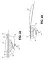
- FIG. 4 ais an end view of the unit and faceplate of FIG. 3 depicted implanted in the mastoid of a recipient;
- FIG. 4 bis a side view of the unit and faceplate arrangement of FIG. 3 ;
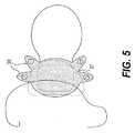
- FIG. 5is a simplified view of another embodiment of a faceplate and receiver/stimulator unit according to the present invention.
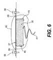
- FIG. 6is an end view of yet another embodiment of a receiver/stimulator unit and faceplate of a prosthetic hearing implant device according to the present invention.
- Known prosthetic hearing implantstypically consist of two main components, an external component including a speech processor 29 , and an internal component including an implanted receiver and stimulator package 22 .
- the external componentincludes a microphone 27 .
- the speech processor 29is, in this illustration, constructed and arranged so that it can fit behind the outer ear 11 and is held in place behind the outer ear 11 via an ear-hook arrangement (not shown). Alternative versions may be worn on the body. Attached to the speech processor 29 via a cable 13 is a transmitter antenna coil 24 that transmits electrical signals to the implanted package 22 via a radio frequency (RF) link.
- RFradio frequency
- the implanted componentincludes a receiver antenna coil 23 for receiving power and data from the transmitter coil 24 .
- a cable 21extends from the implanted receiver and stimulator package 22 to the cochlea 12 and terminates in an electrode array 20 .
- the signals thus receivedare applied by the array 20 to the basilar membrane 8 and the nerve cells within the cochlea 12 thereby stimulating the auditory nerve 9 .
- the operation of such a deviceis described, for example, in U.S. Pat. No. 4,532,930, the contents of which is incorporated herein by reference.
- FIG. 2shows in more detail the surgical placement of the implanted receiver and stimulator package 22 of FIG. 1 , according to conventional practices.
- the package 22is in the form of a capsule, for example a titanium capsule, which houses the necessary circuitry required for the implant to operate as desired.
- the receiver coil 23is shown encapsulated in a material, such as silicone rubber, to provide a protective body and ensure fatigue resilience.
- a magnet 30is shown positioned within the coil to assist in the alignment of the transmitter antenna coil 24 with the receiver antenna coil 23 as discussed previously.
- a bedis drilled into the bone 31 to maintain the package 22 in position. This bed is typically round or ovoid to match the shape of the package.
- the bedis typically made in the mastoid bone and mastoid angle of the parietal bone in the region of the asterion.
- the bedis fashioned initially with a cutting burr, and then completed with a diamond paste burr and a template is typically used to ensure that the bed is fashioned to the correct size.
- the bedmay be drilled down to the lining of the brain, or dura mater 32 , particularly for young children with thin skulls. It is for this reason that a diamond paste burr may be used when approaching the dura and when the dura is exposed, to minimise the risk of tearing of the dura 32 .
- any impact in the direction shown by the arrow A of FIG. 2has the potential for the package to tear the dura 32 and enter the cranial cavity, potentially causing damage to the sensitive structures of the brain.
- an impact to the head region of the recipientparticularly in the direction shown by arrow B, has the potential to dislodge the implant from its bed within the skull bone. Such dislodgement can cause damage to the area of the head adjacent the device as well as discomfort to the recipient. Any dislodgment of the device also has the potential to require further surgical procedures to relocate the device in the desired position within the head of the recipient.
- the present inventionaims to address the above potential problems by positioning the receiver/stimulator package in the head in a manner whereby the package preferably has a low profile and its contents are afforded some protection from impact and from being subsequently damaged and/or dislodged.
- a mastoidectomy and posterior tympanotomyare typically employed to obtain access to the middle ear.
- the mastoidectomy proceduretypically requires removal of material from the mastoid bone behind the ear of the patient via a cutting burr or drill.
- the cortex of the mastoid superior and posterior to the external meatusis removed and the excavation is deepened and air cells are removed superior and posterior to the meatus, exposing the mastoid antrum and the middle ear via the tympanotomy.
- the round windowshould be accessible, thereby allowing a cochleostomy to be performed and the electrode array inserted.
- FIG. 3is a view of one preferred embodiment of the present invention.
- the mastoid cavityis shown by the fine dotted line 35 , which is shown as being located behind the pinna 11 .
- An upper surface in the form of a top faceplate 37 of the implanted receiver/stimulator unit 38(heavy dotted line) is shown positioned above and over the mastoid cavity 35 .
- the receiver/stimulator unit 38has a lower surface that is shaped to be sunk into the mastoid cavity.
- the depicted faceplate 37has flanges 39 which extend outside the perimeter of the implanted receiver/stimulator unit 38 to enable securing of the unit to the skull via surgical screws 36 .
- a receiver antenna coil 40is shown external of the unit 38 and faceplate 37 , in much the same manner as a conventional design as discussed previously.
- FIGS. 4 a and 4 bshow end and side views of the embodiment depicted in FIG. 3 and where appropriate, the same reference numerals are used.
- the receiver/stimulator unit 38extends into the mastoid cavity 35 and is protected by the faceplate 37 which acts as a protecting shield for the unit 38 as well as a stabiliser and means for securing the unit 38 in place.
- a lead 41connects the receiver/stimulator unit 38 to the intracochlear electrodes (not shown) which deliver the electrical stimulation to the nerves within the cochlea.
- the flanges of the faceplate 37can be a simple extension of the upper surface of the receiver/stimulator unit and made from the same material as the rest of the receiver/stimulator unit.
- This materialcan, for example, be titanium, preferably a malleable titanium.
- a titanium flangemay be attached to the titanium case of the receiver/stimulator unit 38 by an appropriate welding or other method.
- the flanges 39are formed so as to be relatively robust whilst also sufficiently malleable so that the entire faceplate 37 can be formed to the shape of the skull surrounding the mastoid cavity by the surgeon using finger pressure only. As the anatomy of this region of the head varies somewhat from individual to individual, it is desirable to form the flanges 39 so that they adopt a flush fit in abutment against the skull.
- the faceplate 37provides protection for the receiver/stimulator unit 38 , it is advantageous to form the faceplate from one of a number of different thicknesses of titanium sheet. In order to withstand impacts of considerable force it is desirable to form the faceplate 37 out of a suitable material such as titanium having a thickness of between 0.3 to 1 mm. As the flanges 39 must be malleable to enable a surgeon to alter their shape with a minimum of force, the flanges 39 are, in the depicted embodiment, made from a thinner material than that of the faceplate 37 . Alternatively, the desired conformability of the flanges 39 could be achieved by altering their geometry rather than their thickness.
- the flanges 39could be of the same thickness as the faceplate 37 , provided that the flanges are in a narrower strip form rather than a wide flange form.
- the flanges 39may be formed from a material, such as titanium, having a thickness of, for example, 0.1 to 0.2 mm.
- the lead 41is preferably pre-coiled so that it can settle into the mastoid cavity 35 , below the receiver/stimulator unit 38 . As is shown in FIGS. 4 a and 4 b , the lead 41 exits the receiver/stimulator unit 38 from a bottom surface thereof. This facilitates routing of the lead to the cochlea via the posterior tympanotomy, which is at the bottom of the mastoid cavity.
- the lead exit point and the formcan have many other geometries and still remain within the spirit of the invention.
- the lead 41may exit from the side of the receiver/stimulator unit and may be straight.
- the faceplate 37 , flanges 39 and screws 36are preferably coated in a silicone rubber or other elastomeric material. In such a case, the screws 36 would be accessed by means of a slit or hole in the silicone above the screw 36 .
- the screws 36 used in the present inventionmay have a number of design variations to satisfy the design requirements of the present application.
- the screws 36may be countersunk for low profile, may have a round head, and may even be resorbable screws. Resorbable screws would assist in holding the implant in place for a short period until the fibrous tissue surrounds and secures the device in place.
- FIG. 5depicts an alternative embodiment of the present invention.
- the faceplatehas relatively narrow flanges 39 that are adapted to assist in enabling the faceplate 37 to conform to the contours of the skull.
- extra screw holesare provided to allow some redundancy in the variations in patient anatomy and the mastoidectomy performed.
- that screwmay be omitted and an alternative screw site used. It should be stressed that this aspect of the present invention is important particularly as it is recommended against fixing the device with screws on both sides of the natural growth lines of the skull.
- the basic size of the faceplate 37is designed to be just larger than the size of the mastoid cavity 35 , allowing the faceplate 37 to be stabilised on the rim of the mastoidectomy.
- the rim of the mastoid cavitymay be easily flattened by the surgeon, for example by drilling, to create a stable seat for the faceplate 37 .
- FIG. 6depicts yet another embodiment of the present invention.
- the faceplate and flangesare not fixedly attached to the receiver/stimulator unit 38 .
- the primary difference between this embodiment and that described in FIGS. 4 a and 4 bis that the faceplate 37 is provided with mechanical catches or clips 45 to hold and maintain the receiver/stimulator unit 38 in place. In this manner, the receiver/stimulator unit is ‘snap-fit’ into the faceplate 37 for securing in place.
- the use of the faceplate and flanges to secure the implant in placeis optional and can be decided upon at the time of surgery.
- the securing mechanismcan be used with non-metallic receiver/stimulator units as there is no need for the faceplate and flanges to be welded onto the unit casing. This enables the present device and method to be employed with ceramic cased implants. It is also envisaged that with a detachable system as shown in FIG. 6 , the faceplate/flange combination could be made from a non-metallic material such as a biocompatible plastic, as welding to the implant case would not be required.
- the platecould be made of polypropylene or polytetrafluoroethylene (PTFE) which have the properties suitable for such an application.
- PTFEpolytetrafluoroethylene
- the receiver/stimulator unit 38is shown as an arbitrarily shaped unit capable of fitting within the bone cavity. It is considered that the receiver/stimulator unit 38 could also be conformable such that the shape of the unit 38 may be altered during the procedure to conform to the specific shape of the bone cavity. In this regard, the unit 38 can be made of a conformable material that allows the shape and form of the unit to be changed without effecting the hermiticity of the unit 38 .
Landscapes
- Health & Medical Sciences (AREA)
- Otolaryngology (AREA)
- Engineering & Computer Science (AREA)
- Biomedical Technology (AREA)
- Nuclear Medicine, Radiotherapy & Molecular Imaging (AREA)
- Radiology & Medical Imaging (AREA)
- Life Sciences & Earth Sciences (AREA)
- Animal Behavior & Ethology (AREA)
- General Health & Medical Sciences (AREA)
- Public Health (AREA)
- Veterinary Medicine (AREA)
- Prostheses (AREA)
Abstract
Description
- 1. A mastoidectomy would be performed in the same manner as a conventional procedure;
- 2. Device placement would be determined using a template shaped like the actual implant device;
- 3. Drill holes would be marked for securing the device in place following the insertion of the electrode array;
- 4. A posterior tympanotomy and cochleostomy would be performed in the same manner as a conventional procedure;
- 5. The electrode array would be inserted into the cochlea;
- 6. The implant package would be placed in position. In this step, the coil connecting the package to the electrode array inserted into the cochlea would preferably coil itself up into the mastoid cavity due to the preformed coil in the lead; and
- 7. The implant package would be secured in place via screws or the like.
Claims (23)
Priority Applications (1)
| Application Number | Priority Date | Filing Date | Title |
|---|---|---|---|
| US13/176,349US8774929B2 (en) | 2002-08-09 | 2011-07-05 | Cochlear implant component having a unitary faceplate |
Applications Claiming Priority (7)
| Application Number | Priority Date | Filing Date | Title |
|---|---|---|---|
| AU2002950754AAU2002950754A0 (en) | 2002-08-09 | 2002-08-09 | Mechanical design for a cochlear implant |
| AU2002950754 | 2002-08-09 | ||
| PCT/AU2003/001012WO2004014270A1 (en) | 2002-08-09 | 2003-08-11 | Mechanical design for a cochlear implant |
| US59091604P | 2004-07-26 | 2004-07-26 | |
| US62957804P | 2004-11-22 | 2004-11-22 | |
| US52379505A | 2005-06-30 | 2005-06-30 | |
| US13/176,349US8774929B2 (en) | 2002-08-09 | 2011-07-05 | Cochlear implant component having a unitary faceplate |
Related Parent Applications (3)
| Application Number | Title | Priority Date | Filing Date |
|---|---|---|---|
| US10/523,795DivisionUS7974700B1 (en) | 2002-08-09 | 2003-08-11 | Cochlear implant component having a unitary faceplate |
| PCT/AU2003/001012DivisionWO2004014270A1 (en) | 2002-08-09 | 2003-08-11 | Mechanical design for a cochlear implant |
| US52379505ADivision | 2002-08-09 | 2005-06-30 |
Publications (2)
| Publication Number | Publication Date |
|---|---|
| US20110264170A1 US20110264170A1 (en) | 2011-10-27 |
| US8774929B2true US8774929B2 (en) | 2014-07-08 |
Family
ID=27809841
Family Applications (1)
| Application Number | Title | Priority Date | Filing Date |
|---|---|---|---|
| US13/176,349Expired - LifetimeUS8774929B2 (en) | 2002-08-09 | 2011-07-05 | Cochlear implant component having a unitary faceplate |
Country Status (3)
| Country | Link |
|---|---|
| US (1) | US8774929B2 (en) |
| AU (1) | AU2002950754A0 (en) |
| WO (1) | WO2004014270A1 (en) |
Cited By (1)
| Publication number | Priority date | Publication date | Assignee | Title |
|---|---|---|---|---|
| US11497910B2 (en)* | 2017-07-20 | 2022-11-15 | Advanced Bionics Ag | Cochlear implants having detachable fixation elements and associated systems and methods |
Families Citing this family (26)
| Publication number | Priority date | Publication date | Assignee | Title |
|---|---|---|---|---|
| AU2002950754A0 (en) | 2002-08-09 | 2002-09-12 | Cochlear Limited | Mechanical design for a cochlear implant |
| AU2002950755A0 (en) | 2002-08-09 | 2002-09-12 | Cochlear Limited | Fixation system for a cochlear implant |
| US7974700B1 (en) | 2002-08-09 | 2011-07-05 | Cochlear Limited | Cochlear implant component having a unitary faceplate |
| AU2003901867A0 (en) | 2003-04-17 | 2003-05-08 | Cochlear Limited | Osseointegration fixation system for an implant |
| EP1737533B1 (en)* | 2004-03-15 | 2014-07-16 | Med-El Elektromedizinische Geräte GmbH | Cochlear implant electrode with adjustable subdivision for middle ear functions |
| US8489195B2 (en) | 2005-11-10 | 2013-07-16 | Cochlear Limited | Arrangement for the fixation of an implantable medical device |
| US7792587B2 (en) | 2006-09-12 | 2010-09-07 | Med-El Elektromedizinische Geraete Gmbh | Middle ear fixation structure |
| WO2009036006A1 (en)* | 2007-09-10 | 2009-03-19 | Med-El Elektromedizinische Geraete Gmbh | Impact protection for implants |
| US8532783B2 (en) | 2007-09-10 | 2013-09-10 | Med-El Elektromedizinische Geraete Gmbh | Impact protection for implants |
| AU2012202469B2 (en)* | 2007-09-10 | 2013-09-26 | Med-El Elektromedizinische Geraete Gmbh | Impact protection for implants |
| US10419861B2 (en) | 2011-05-24 | 2019-09-17 | Cochlear Limited | Convertibility of a bone conduction device |
| US9609440B2 (en)* | 2011-05-30 | 2017-03-28 | Advanced Bionics Ag | Template for implanting a housing of a hearing instrument |
| US20130096366A1 (en) | 2011-10-12 | 2013-04-18 | Wim Bervoets | Implantable medical device |
| US9049527B2 (en) | 2012-08-28 | 2015-06-02 | Cochlear Limited | Removable attachment of a passive transcutaneous bone conduction device with limited skin deformation |
| CN107683162B (en) | 2015-05-28 | 2019-03-29 | 领先仿生公司 | Cochlear implant and the method for keeping its MRI compatible, cochlear implant system |
| WO2017027045A1 (en)* | 2015-08-13 | 2017-02-16 | Advanced Bionics Ag | Cochlear implants having bone-anchored magnet apparatus and associated methods |
| EP3377172B1 (en) | 2015-11-20 | 2021-07-28 | Advanced Bionics AG | Cochlear implants and magnets for use with same |
| WO2017105511A1 (en) | 2015-12-18 | 2017-06-22 | Advanced Bionics Ag | Cochlear implants having mri-compatible magnet apparatus |
| WO2017105510A1 (en) | 2015-12-18 | 2017-06-22 | Advanced Bionics Ag | Cochlear implants having mri-compatible magnet apparatus and associated methods |
| US10646718B2 (en) | 2016-11-15 | 2020-05-12 | Advanced Bionics Ag | Cochlear implants and magnets for use with same |
| WO2018190813A1 (en) | 2017-04-11 | 2018-10-18 | Advanced Bionics Ag | Cochlear implants with retrofit magnets |
| WO2018199936A1 (en) | 2017-04-25 | 2018-11-01 | Advanced Bionics Ag | Cochlear implants having impact resistant mri-compatible magnet apparatus |
| EP3630265A1 (en) | 2017-05-22 | 2020-04-08 | Advanced Bionics AG | Methods and apparatus for use with cochlear implants having magnet apparatus with magnetic material particles |
| US10646712B2 (en) | 2017-09-13 | 2020-05-12 | Advanced Bionics Ag | Cochlear implants having MRI-compatible magnet apparatus |
| EP3700622B1 (en) | 2017-10-26 | 2022-10-19 | Advanced Bionics AG | Headpieces and implantable cochlear stimulation systems including the same |
| CN112118888B (en) | 2018-02-15 | 2024-10-22 | 领先仿生公司 | Head-mounted device and implantable cochlear stimulation system including the same |
Citations (51)
| Publication number | Priority date | Publication date | Assignee | Title |
|---|---|---|---|---|
| US2487038A (en) | 1944-03-25 | 1949-11-08 | Sonotone Corp | Ear insert for earphones |
| US2641328A (en) | 1948-07-26 | 1953-06-09 | John R Beaudry | Mechanical hearing aid |
| US3768977A (en)* | 1972-03-31 | 1973-10-30 | R Brumfield | Integral blood oxygenator and heat exchanger |
| US4055233A (en) | 1975-12-22 | 1977-10-25 | Electronic Engineering Co. Of California | Ear coupler |
| US4333469A (en) | 1979-07-20 | 1982-06-08 | Telectronics Pty. Ltd. | Bone growth stimulator |
| WO1983000999A1 (en) | 1981-09-18 | 1983-03-31 | Hochmair, Ingeborg, J. | Single channel auditory stimulation system |
| US4488561A (en) | 1983-06-27 | 1984-12-18 | Medtronic, Inc. | Pacing lead with insertable memory coil |
| US4532930A (en) | 1983-04-11 | 1985-08-06 | Commonwealth Of Australia, Dept. Of Science & Technology | Cochlear implant system for an auditory prosthesis |
| US4612915A (en) | 1985-05-23 | 1986-09-23 | Xomed, Inc. | Direct bone conduction hearing aid device |
| US4744792A (en) | 1985-01-22 | 1988-05-17 | Richards Medical Company | Middle ear ventilating tube |
| US4904233A (en) | 1985-05-10 | 1990-02-27 | Haakansson Bo | Arrangement in a hearing aid device |
| US4986831A (en) | 1988-04-25 | 1991-01-22 | Angeion Corporation | Medical implant |
| US5176620A (en) | 1990-10-17 | 1993-01-05 | Samuel Gilman | Hearing aid having a liquid transmission means communicative with the cochlea and method of use thereof |
| US5277694A (en) | 1991-02-13 | 1994-01-11 | Implex Gmbh | Electromechanical transducer for implantable hearing aids |
| US5282253A (en) | 1991-02-26 | 1994-01-25 | Pan Communications, Inc. | Bone conduction microphone mount |
| WO1994029932A1 (en) | 1993-06-07 | 1994-12-22 | Cochlear Pty. Ltd. | Percutaneous connector system |
| US5443493A (en) | 1989-09-22 | 1995-08-22 | Alfred E. Mann Foundation For Scientific Research | Cochlea stimulating electrode assembly, insertion tool, holder and method of implantation |
| US5558618A (en) | 1995-01-23 | 1996-09-24 | Maniglia; Anthony J. | Semi-implantable middle ear hearing device |
| US5572594A (en) | 1994-09-27 | 1996-11-05 | Devoe; Lambert | Ear canal device holder |
| WO1997005673A1 (en) | 1995-08-01 | 1997-02-13 | Cochlear Pty. Limited | Electrical connector for therapeutic devices |
| WO1997036457A1 (en) | 1996-03-25 | 1997-10-02 | Lesinski S George | Attaching an implantable hearing aid microactuator |
| US5738521A (en) | 1996-07-19 | 1998-04-14 | Biolectron, Inc. | Method for accelerating osseointegration of metal bone implants using electrical stimulation |
| US5814095A (en) | 1996-09-18 | 1998-09-29 | Implex Gmbh Spezialhorgerate | Implantable microphone and implantable hearing aids utilizing same |
| WO1999006108A1 (en) | 1997-08-01 | 1999-02-11 | Alfred E. Mann Foundation For Scientific Research | Implantable device with improved battery recharging and powering configuration |
| US5881158A (en) | 1996-05-24 | 1999-03-09 | United States Surgical Corporation | Microphones for an implantable hearing aid |
| US5906635A (en) | 1995-01-23 | 1999-05-25 | Maniglia; Anthony J. | Electromagnetic implantable hearing device for improvement of partial and total sensoryneural hearing loss |
| US5999632A (en) | 1997-11-26 | 1999-12-07 | Implex Aktiengesellschaft Hearing Technology | Fixation element for an implantable microphone |
| US6042380A (en) | 1997-11-25 | 2000-03-28 | Discotech Medical Technologies, Ltd. | Inflatable dental implant for receipt and support of a dental prosthesis |
| US6070105A (en) | 1997-09-02 | 2000-05-30 | Advanced Bionics Corporation | Modiolus-hugging cochlear electrodes |
| US6125302A (en) | 1997-09-02 | 2000-09-26 | Advanced Bionics Corporation | Precurved modiolar-hugging cochlear electrode |
| US6132384A (en) | 1996-06-26 | 2000-10-17 | Medtronic, Inc. | Sensor, method of sensor implant and system for treatment of respiratory disorders |
| WO2001010369A1 (en) | 1999-08-06 | 2001-02-15 | The University Of Melbourne | Improved cochlear implant package |
| US20020019669A1 (en) | 1999-11-29 | 2002-02-14 | Epic Biosonics Inc. | Totally implantable cochlear prosthesis |
| US6427086B1 (en)* | 1997-10-27 | 2002-07-30 | Neuropace, Inc. | Means and method for the intracranial placement of a neurostimulator |
| US6516228B1 (en) | 2000-02-07 | 2003-02-04 | Epic Biosonics Inc. | Implantable microphone for use with a hearing aid or cochlear prosthesis |
| US6537200B2 (en) | 2000-03-28 | 2003-03-25 | Cochlear Limited | Partially or fully implantable hearing system |
| US6565503B2 (en) | 2000-04-13 | 2003-05-20 | Cochlear Limited | At least partially implantable system for rehabilitation of hearing disorder |
| US6575894B2 (en) | 2000-04-13 | 2003-06-10 | Cochlear Limited | At least partially implantable system for rehabilitation of a hearing disorder |
| WO2003070133A1 (en) | 2002-02-22 | 2003-08-28 | Cochlear Limited | An insertion device for an electrode array |
| WO2003092326A1 (en) | 2002-04-23 | 2003-11-06 | Cochlear Limited | Mri-compatible cochlear implant |
| WO2004014269A1 (en) | 2002-08-09 | 2004-02-19 | Cochlear Limited | Fixation system for an implantable medical device |
| WO2004014270A1 (en) | 2002-08-09 | 2004-02-19 | Cochlear Limited | Mechanical design for a cochlear implant |
| US6697674B2 (en) | 2000-04-13 | 2004-02-24 | Cochlear Limited | At least partially implantable system for rehabilitation of a hearing disorder |
| US6730015B2 (en) | 2001-06-01 | 2004-05-04 | Mike Schugt | Flexible transducer supports |
| US20040260361A1 (en) | 2003-04-17 | 2004-12-23 | Peter Gibson | Implantable device having osseointegrating protuberances |
| US6840919B1 (en) | 1997-12-18 | 2005-01-11 | Osseofon Ab | Percutaneous bone anchored transferring device |
| US7043040B2 (en) | 2001-06-21 | 2006-05-09 | P&B Research Ab | Hearing aid apparatus |
| RU2282426C1 (en) | 2004-12-27 | 2006-08-27 | Федеральное государственное учреждение Российский научно-практический центр аудиологии и слухопротезирования Министерства здравоохранения и социального развития РФ | Method for fixing cochlear implant on cranium surface |
| WO2007053882A1 (en) | 2005-11-10 | 2007-05-18 | Cochlear Limited | Arrangement for the fixation of an implantable medical device |
| WO2009099658A2 (en) | 2008-02-06 | 2009-08-13 | Rosemount Inc. | Adjustable resonance frequency vibration power harvester |
| US20110160855A1 (en) | 2002-08-09 | 2011-06-30 | Peter Gibson | Cochlear implant component having a unitary faceplate |
- 2002
- 2002-08-09AUAU2002950754Apatent/AU2002950754A0/ennot_activeAbandoned
- 2003
- 2003-08-11WOPCT/AU2003/001012patent/WO2004014270A1/ennot_activeApplication Discontinuation
- 2011
- 2011-07-05USUS13/176,349patent/US8774929B2/ennot_activeExpired - Lifetime
Patent Citations (55)
| Publication number | Priority date | Publication date | Assignee | Title |
|---|---|---|---|---|
| US2487038A (en) | 1944-03-25 | 1949-11-08 | Sonotone Corp | Ear insert for earphones |
| US2641328A (en) | 1948-07-26 | 1953-06-09 | John R Beaudry | Mechanical hearing aid |
| US3768977A (en)* | 1972-03-31 | 1973-10-30 | R Brumfield | Integral blood oxygenator and heat exchanger |
| US4055233A (en) | 1975-12-22 | 1977-10-25 | Electronic Engineering Co. Of California | Ear coupler |
| US4333469A (en) | 1979-07-20 | 1982-06-08 | Telectronics Pty. Ltd. | Bone growth stimulator |
| WO1983000999A1 (en) | 1981-09-18 | 1983-03-31 | Hochmair, Ingeborg, J. | Single channel auditory stimulation system |
| US4532930A (en) | 1983-04-11 | 1985-08-06 | Commonwealth Of Australia, Dept. Of Science & Technology | Cochlear implant system for an auditory prosthesis |
| US4488561A (en) | 1983-06-27 | 1984-12-18 | Medtronic, Inc. | Pacing lead with insertable memory coil |
| US4744792A (en) | 1985-01-22 | 1988-05-17 | Richards Medical Company | Middle ear ventilating tube |
| US4904233A (en) | 1985-05-10 | 1990-02-27 | Haakansson Bo | Arrangement in a hearing aid device |
| US4612915A (en) | 1985-05-23 | 1986-09-23 | Xomed, Inc. | Direct bone conduction hearing aid device |
| US4986831A (en) | 1988-04-25 | 1991-01-22 | Angeion Corporation | Medical implant |
| US5443493A (en) | 1989-09-22 | 1995-08-22 | Alfred E. Mann Foundation For Scientific Research | Cochlea stimulating electrode assembly, insertion tool, holder and method of implantation |
| US5176620A (en) | 1990-10-17 | 1993-01-05 | Samuel Gilman | Hearing aid having a liquid transmission means communicative with the cochlea and method of use thereof |
| US5277694A (en) | 1991-02-13 | 1994-01-11 | Implex Gmbh | Electromechanical transducer for implantable hearing aids |
| US5282253A (en) | 1991-02-26 | 1994-01-25 | Pan Communications, Inc. | Bone conduction microphone mount |
| WO1994029932A1 (en) | 1993-06-07 | 1994-12-22 | Cochlear Pty. Ltd. | Percutaneous connector system |
| US5572594A (en) | 1994-09-27 | 1996-11-05 | Devoe; Lambert | Ear canal device holder |
| US5906635A (en) | 1995-01-23 | 1999-05-25 | Maniglia; Anthony J. | Electromagnetic implantable hearing device for improvement of partial and total sensoryneural hearing loss |
| US5558618A (en) | 1995-01-23 | 1996-09-24 | Maniglia; Anthony J. | Semi-implantable middle ear hearing device |
| WO1997005673A1 (en) | 1995-08-01 | 1997-02-13 | Cochlear Pty. Limited | Electrical connector for therapeutic devices |
| WO1997036457A1 (en) | 1996-03-25 | 1997-10-02 | Lesinski S George | Attaching an implantable hearing aid microactuator |
| US5881158A (en) | 1996-05-24 | 1999-03-09 | United States Surgical Corporation | Microphones for an implantable hearing aid |
| US6381336B1 (en)* | 1996-05-24 | 2002-04-30 | S. George Lesinski | Microphones for an implatable hearing aid |
| US6132384A (en) | 1996-06-26 | 2000-10-17 | Medtronic, Inc. | Sensor, method of sensor implant and system for treatment of respiratory disorders |
| US5738521A (en) | 1996-07-19 | 1998-04-14 | Biolectron, Inc. | Method for accelerating osseointegration of metal bone implants using electrical stimulation |
| US5814095A (en) | 1996-09-18 | 1998-09-29 | Implex Gmbh Spezialhorgerate | Implantable microphone and implantable hearing aids utilizing same |
| WO1999006108A1 (en) | 1997-08-01 | 1999-02-11 | Alfred E. Mann Foundation For Scientific Research | Implantable device with improved battery recharging and powering configuration |
| US6070105A (en) | 1997-09-02 | 2000-05-30 | Advanced Bionics Corporation | Modiolus-hugging cochlear electrodes |
| US6125302A (en) | 1997-09-02 | 2000-09-26 | Advanced Bionics Corporation | Precurved modiolar-hugging cochlear electrode |
| US6427086B1 (en)* | 1997-10-27 | 2002-07-30 | Neuropace, Inc. | Means and method for the intracranial placement of a neurostimulator |
| US6042380A (en) | 1997-11-25 | 2000-03-28 | Discotech Medical Technologies, Ltd. | Inflatable dental implant for receipt and support of a dental prosthesis |
| US5999632A (en) | 1997-11-26 | 1999-12-07 | Implex Aktiengesellschaft Hearing Technology | Fixation element for an implantable microphone |
| US6840919B1 (en) | 1997-12-18 | 2005-01-11 | Osseofon Ab | Percutaneous bone anchored transferring device |
| WO2001010369A1 (en) | 1999-08-06 | 2001-02-15 | The University Of Melbourne | Improved cochlear implant package |
| US20020019669A1 (en) | 1999-11-29 | 2002-02-14 | Epic Biosonics Inc. | Totally implantable cochlear prosthesis |
| US6516228B1 (en) | 2000-02-07 | 2003-02-04 | Epic Biosonics Inc. | Implantable microphone for use with a hearing aid or cochlear prosthesis |
| US6537200B2 (en) | 2000-03-28 | 2003-03-25 | Cochlear Limited | Partially or fully implantable hearing system |
| US6697674B2 (en) | 2000-04-13 | 2004-02-24 | Cochlear Limited | At least partially implantable system for rehabilitation of a hearing disorder |
| US6565503B2 (en) | 2000-04-13 | 2003-05-20 | Cochlear Limited | At least partially implantable system for rehabilitation of hearing disorder |
| US6575894B2 (en) | 2000-04-13 | 2003-06-10 | Cochlear Limited | At least partially implantable system for rehabilitation of a hearing disorder |
| US6730015B2 (en) | 2001-06-01 | 2004-05-04 | Mike Schugt | Flexible transducer supports |
| US7043040B2 (en) | 2001-06-21 | 2006-05-09 | P&B Research Ab | Hearing aid apparatus |
| WO2003070133A1 (en) | 2002-02-22 | 2003-08-28 | Cochlear Limited | An insertion device for an electrode array |
| WO2003092326A1 (en) | 2002-04-23 | 2003-11-06 | Cochlear Limited | Mri-compatible cochlear implant |
| WO2004014270A1 (en) | 2002-08-09 | 2004-02-19 | Cochlear Limited | Mechanical design for a cochlear implant |
| WO2004014269A1 (en) | 2002-08-09 | 2004-02-19 | Cochlear Limited | Fixation system for an implantable medical device |
| US20060116743A1 (en) | 2002-08-09 | 2006-06-01 | Peter Gibson | Fixation system for an implantable medical device |
| US20110160855A1 (en) | 2002-08-09 | 2011-06-30 | Peter Gibson | Cochlear implant component having a unitary faceplate |
| US7974700B1 (en) | 2002-08-09 | 2011-07-05 | Cochlear Limited | Cochlear implant component having a unitary faceplate |
| US20040260361A1 (en) | 2003-04-17 | 2004-12-23 | Peter Gibson | Implantable device having osseointegrating protuberances |
| RU2282426C1 (en) | 2004-12-27 | 2006-08-27 | Федеральное государственное учреждение Российский научно-практический центр аудиологии и слухопротезирования Министерства здравоохранения и социального развития РФ | Method for fixing cochlear implant on cranium surface |
| WO2007053882A1 (en) | 2005-11-10 | 2007-05-18 | Cochlear Limited | Arrangement for the fixation of an implantable medical device |
| US20090099658A1 (en) | 2005-11-10 | 2009-04-16 | Cochlear Limited | Arrangement for the fixation of an implantable medical device |
| WO2009099658A2 (en) | 2008-02-06 | 2009-08-13 | Rosemount Inc. | Adjustable resonance frequency vibration power harvester |
Non-Patent Citations (13)
| Title |
|---|
| International Application No. PCT/AU03/01004, International Preliminary Examination Report mailed on Nov. 22, 2004, 3 Pages. |
| International Application No. PCT/AU03/01004, International Search Report mailed on Oct. 13, 2003, 2 Pages. |
| International Application No. PCT/AU03/01004, Written Opinion mailed on Sep. 9, 2006, 3 Pages. |
| International Application No. PCT/AU06/001632, International Preliminary Report on Patentability mailed on May 14, 2008, 6 Pages. |
| International Application No. PCT/AU06/001632, International Search Report mailed on Dec. 1, 2006, 3 Pages. |
| International Application No. PCT/AU06/001632, Written Opinion mailed on Dec. 1, 2006, 5 Pages. |
| International Application No. PCT/AU2000/000936, International Preliminary Examination Report mailed on Jun. 8, 2001, 3 Pages. |
| International Application No. PCT/AU2003/000229, International Preliminary Examination Report mailed on May 24, 2004, 6 Pages. |
| International Application No. PCT/AU2003/000229, International Search Report mailed on May 5, 2003, 5 Pages. |
| International Application No. PCT/AU2003/000229, Written Opinion mailed on Jun. 30, 2003, 6 Pages. |
| International Application No. PCT/AU2003/001012, International Preliminary Examination Report mailed on Nov. 23, 2004, 3 Pages. |
| International Application No. PCT/AU2003/001012, International Search Report mailed on Oct. 13, 2005, 5 Pages. |
| International Application No. PCT/AU2003/001012, Written Opinion mailed on Feb. 23, 2004, 3 Pages. |
Cited By (2)
| Publication number | Priority date | Publication date | Assignee | Title |
|---|---|---|---|---|
| US11497910B2 (en)* | 2017-07-20 | 2022-11-15 | Advanced Bionics Ag | Cochlear implants having detachable fixation elements and associated systems and methods |
| US11819692B2 (en) | 2017-07-20 | 2023-11-21 | Advanced Bionics Ag | Cochlear implants having detachable fixation elements and associated systems and methods |
Also Published As
| Publication number | Publication date |
|---|---|
| US20110264170A1 (en) | 2011-10-27 |
| AU2002950754A0 (en) | 2002-09-12 |
| WO2004014270A1 (en) | 2004-02-19 |
Similar Documents
| Publication | Publication Date | Title |
|---|---|---|
| US8774929B2 (en) | Cochlear implant component having a unitary faceplate | |
| US11439834B2 (en) | Fixation system for an implantable medical device | |
| US7881800B2 (en) | Cochlear implant having a repositionable implantable housing | |
| US10022535B2 (en) | Securing an implanted medical device in a patient | |
| US6629923B2 (en) | At least partially implantable hearing system with direct mechanical stimulation of a lymphatic space of the inner ear | |
| US6565503B2 (en) | At least partially implantable system for rehabilitation of hearing disorder | |
| US8945216B2 (en) | Objective fitting of a hearing prosthesis | |
| US7376563B2 (en) | System for rehabilitation of a hearing disorder | |
| US6325755B1 (en) | Mountable transducer assembly with removable sleeve | |
| US20080312717A1 (en) | Hybrid Cochlear Implant | |
| US7974700B1 (en) | Cochlear implant component having a unitary faceplate | |
| US20110112355A1 (en) | Implantable sound sensor for hearing prostheses | |
| US12318605B2 (en) | Implantable device migration control | |
| US20130225912A1 (en) | Combined functional component and implantable actuator positioning mechanism | |
| US20240214754A1 (en) | Intracutaneous implantation techniques | |
| Carr et al. | Electroacoustics |
Legal Events
| Date | Code | Title | Description |
|---|---|---|---|
| AS | Assignment | Owner name:COCHLEAR LIMITED, AUSTRALIA Free format text:ASSIGNMENT OF ASSIGNORS INTEREST;ASSIGNOR:GIBSON, PETER;REEL/FRAME:033010/0408 Effective date:20050222 | |
| FEPP | Fee payment procedure | Free format text:MAINTENANCE FEE REMINDER MAILED (ORIGINAL EVENT CODE: REM.) | |
| LAPS | Lapse for failure to pay maintenance fees | Free format text:PATENT EXPIRED FOR FAILURE TO PAY MAINTENANCE FEES (ORIGINAL EVENT CODE: EXP.) | |
| STCH | Information on status: patent discontinuation | Free format text:PATENT EXPIRED DUE TO NONPAYMENT OF MAINTENANCE FEES UNDER 37 CFR 1.362 | |
| FP | Lapsed due to failure to pay maintenance fee | Effective date:20180708 | |
| PRDP | Patent reinstated due to the acceptance of a late maintenance fee | Effective date:20191226 | |
| FEPP | Fee payment procedure | Free format text:PETITION RELATED TO MAINTENANCE FEES FILED (ORIGINAL EVENT CODE: PMFP); ENTITY STATUS OF PATENT OWNER: LARGE ENTITY Free format text:SURCHARGE, PETITION TO ACCEPT PYMT AFTER EXP, UNINTENTIONAL (ORIGINAL EVENT CODE: M1558); ENTITY STATUS OF PATENT OWNER: LARGE ENTITY Free format text:PETITION RELATED TO MAINTENANCE FEES GRANTED (ORIGINAL EVENT CODE: PMFG); ENTITY STATUS OF PATENT OWNER: LARGE ENTITY | |
| MAFP | Maintenance fee payment | Free format text:PAYMENT OF MAINTENANCE FEE, 4TH YEAR, LARGE ENTITY (ORIGINAL EVENT CODE: M1551); ENTITY STATUS OF PATENT OWNER: LARGE ENTITY Year of fee payment:4 | |
| STCF | Information on status: patent grant | Free format text:PATENTED CASE | |
| MAFP | Maintenance fee payment | Free format text:PAYMENT OF MAINTENANCE FEE, 8TH YEAR, LARGE ENTITY (ORIGINAL EVENT CODE: M1552); ENTITY STATUS OF PATENT OWNER: LARGE ENTITY Year of fee payment:8 |