US8773507B2 - Defocusing feature matching system to measure camera pose with interchangeable lens cameras - Google Patents
Defocusing feature matching system to measure camera pose with interchangeable lens camerasDownload PDFInfo
- Publication number
- US8773507B2 US8773507B2US12/853,181US85318110AUS8773507B2US 8773507 B2US8773507 B2US 8773507B2US 85318110 AUS85318110 AUS 85318110AUS 8773507 B2US8773507 B2US 8773507B2
- Authority
- US
- United States
- Prior art keywords
- camera
- information
- lens
- lens assembly
- aperture
- Prior art date
- Legal status (The legal status is an assumption and is not a legal conclusion. Google has not performed a legal analysis and makes no representation as to the accuracy of the status listed.)
- Active, expires
Links
- 238000000034methodMethods0.000claimsdescription23
- 238000003384imaging methodMethods0.000claimsdescription9
- 230000009466transformationEffects0.000claimsdescription5
- 230000011514reflexEffects0.000claimsdescription3
- 230000000712assemblyEffects0.000claims2
- 238000000429assemblyMethods0.000claims2
- 239000002131composite materialSubstances0.000claims2
- 230000003287optical effectEffects0.000description8
- 230000010287polarizationEffects0.000description5
- 230000006870functionEffects0.000description3
- 238000012986modificationMethods0.000description3
- 230000004048modificationEffects0.000description3
- 239000002245particleSubstances0.000description3
- 238000012545processingMethods0.000description3
- 239000003086colorantSubstances0.000description2
- 238000004891communicationMethods0.000description2
- 238000005516engineering processMethods0.000description2
- 239000000835fiberSubstances0.000description2
- 239000000443aerosolSubstances0.000description1
- 238000004590computer programMethods0.000description1
- 230000003247decreasing effectEffects0.000description1
- 238000013461designMethods0.000description1
- 238000001514detection methodMethods0.000description1
- 238000005286illuminationMethods0.000description1
- 238000005259measurementMethods0.000description1
- 230000005055memory storageEffects0.000description1
- 230000008569processEffects0.000description1
- 238000000926separation methodMethods0.000description1
- 239000007787solidSubstances0.000description1
- 238000012549trainingMethods0.000description1
- 238000012546transferMethods0.000description1
- 230000001131transforming effectEffects0.000description1
- 238000013519translationMethods0.000description1
Images


Classifications
- H—ELECTRICITY
- H04—ELECTRIC COMMUNICATION TECHNIQUE
- H04N—PICTORIAL COMMUNICATION, e.g. TELEVISION
- H04N13/00—Stereoscopic video systems; Multi-view video systems; Details thereof
- H04N13/20—Image signal generators
- H04N13/204—Image signal generators using stereoscopic image cameras
- G—PHYSICS
- G02—OPTICS
- G02B—OPTICAL ELEMENTS, SYSTEMS OR APPARATUS
- G02B7/00—Mountings, adjusting means, or light-tight connections, for optical elements
- G02B7/28—Systems for automatic generation of focusing signals
- G02B7/34—Systems for automatic generation of focusing signals using different areas in a pupil plane
- G—PHYSICS
- G03—PHOTOGRAPHY; CINEMATOGRAPHY; ANALOGOUS TECHNIQUES USING WAVES OTHER THAN OPTICAL WAVES; ELECTROGRAPHY; HOLOGRAPHY
- G03B—APPARATUS OR ARRANGEMENTS FOR TAKING PHOTOGRAPHS OR FOR PROJECTING OR VIEWING THEM; APPARATUS OR ARRANGEMENTS EMPLOYING ANALOGOUS TECHNIQUES USING WAVES OTHER THAN OPTICAL WAVES; ACCESSORIES THEREFOR
- G03B17/00—Details of cameras or camera bodies; Accessories therefor
- G03B17/02—Bodies
- G03B17/12—Bodies with means for supporting objectives, supplementary lenses, filters, masks, or turrets
- G03B17/14—Bodies with means for supporting objectives, supplementary lenses, filters, masks, or turrets interchangeably
- G—PHYSICS
- G03—PHOTOGRAPHY; CINEMATOGRAPHY; ANALOGOUS TECHNIQUES USING WAVES OTHER THAN OPTICAL WAVES; ELECTROGRAPHY; HOLOGRAPHY
- G03B—APPARATUS OR ARRANGEMENTS FOR TAKING PHOTOGRAPHS OR FOR PROJECTING OR VIEWING THEM; APPARATUS OR ARRANGEMENTS EMPLOYING ANALOGOUS TECHNIQUES USING WAVES OTHER THAN OPTICAL WAVES; ACCESSORIES THEREFOR
- G03B17/00—Details of cameras or camera bodies; Accessories therefor
- G03B17/56—Accessories
- G03B17/565—Optical accessories, e.g. converters for close-up photography, tele-convertors, wide-angle convertors
- G—PHYSICS
- G03—PHOTOGRAPHY; CINEMATOGRAPHY; ANALOGOUS TECHNIQUES USING WAVES OTHER THAN OPTICAL WAVES; ELECTROGRAPHY; HOLOGRAPHY
- G03B—APPARATUS OR ARRANGEMENTS FOR TAKING PHOTOGRAPHS OR FOR PROJECTING OR VIEWING THEM; APPARATUS OR ARRANGEMENTS EMPLOYING ANALOGOUS TECHNIQUES USING WAVES OTHER THAN OPTICAL WAVES; ACCESSORIES THEREFOR
- G03B19/00—Cameras
- G03B19/02—Still-picture cameras
- G03B19/12—Reflex cameras with single objective and a movable reflector or a partly-transmitting mirror
- G—PHYSICS
- G03—PHOTOGRAPHY; CINEMATOGRAPHY; ANALOGOUS TECHNIQUES USING WAVES OTHER THAN OPTICAL WAVES; ELECTROGRAPHY; HOLOGRAPHY
- G03B—APPARATUS OR ARRANGEMENTS FOR TAKING PHOTOGRAPHS OR FOR PROJECTING OR VIEWING THEM; APPARATUS OR ARRANGEMENTS EMPLOYING ANALOGOUS TECHNIQUES USING WAVES OTHER THAN OPTICAL WAVES; ACCESSORIES THEREFOR
- G03B35/00—Stereoscopic photography
- G—PHYSICS
- G03—PHOTOGRAPHY; CINEMATOGRAPHY; ANALOGOUS TECHNIQUES USING WAVES OTHER THAN OPTICAL WAVES; ELECTROGRAPHY; HOLOGRAPHY
- G03B—APPARATUS OR ARRANGEMENTS FOR TAKING PHOTOGRAPHS OR FOR PROJECTING OR VIEWING THEM; APPARATUS OR ARRANGEMENTS EMPLOYING ANALOGOUS TECHNIQUES USING WAVES OTHER THAN OPTICAL WAVES; ACCESSORIES THEREFOR
- G03B9/00—Exposure-making shutters; Diaphragms
- G03B9/02—Diaphragms
- H—ELECTRICITY
- H04—ELECTRIC COMMUNICATION TECHNIQUE
- H04N—PICTORIAL COMMUNICATION, e.g. TELEVISION
- H04N23/00—Cameras or camera modules comprising electronic image sensors; Control thereof
- H04N23/50—Constructional details
- H04N23/55—Optical parts specially adapted for electronic image sensors; Mounting thereof
- H—ELECTRICITY
- H04—ELECTRIC COMMUNICATION TECHNIQUE
- H04N—PICTORIAL COMMUNICATION, e.g. TELEVISION
- H04N23/00—Cameras or camera modules comprising electronic image sensors; Control thereof
- H04N23/70—Circuitry for compensating brightness variation in the scene
- H—ELECTRICITY
- H04—ELECTRIC COMMUNICATION TECHNIQUE
- H04N—PICTORIAL COMMUNICATION, e.g. TELEVISION
- H04N23/00—Cameras or camera modules comprising electronic image sensors; Control thereof
- H04N23/70—Circuitry for compensating brightness variation in the scene
- H04N23/743—Bracketing, i.e. taking a series of images with varying exposure conditions
Definitions
- aperture coded imagingAnother technique is called aperture coded imaging. This technique uses off-axis apertures to measure the depth and location of a scattering site. The shifts in the images caused by these off-axis apertures are monitored, to determine the three-dimensional position of the site or sites.
- U.S. Pat. No. 7,006,132describes using lens laws and self similar triangle analysis to find the geometrical center (X.sub.0,Y.sub.0) of the image pair, and then to solve for the image separation.
- thiscan determine the pose of a camera that is obtaining the information, and the information from the camera, to determine 3D information about structures that is pieced together from multiple different images.
- US 2009/0295908describes how camera pose can be simultaneously measured by using an additional set of apertures that measure a pose of the camera relative to the object when using a feature matching algorithm, using the same apertures that are used for defocusing.
- the present applicationdescribes a lens system and assembly that is intended for attachment to an SLR camera or other camera with a replaceable lens assembly, and which includes coded apertures of a type that can be used for determining defocus information.
- An embodimentdescribes using a camera for taking pictures and also for obtaining 3D information.
- FIG. 1shows the camera with a picture taking lens
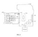
- FIG. 2shows the camera with a special defocus lens assembly on the same body as in FIG. 1 , and a computer system.
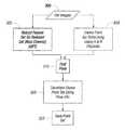
- FIG. 3shows a general flowchart of the operation of the image determination and processing according to an embodiment.
- a camera systemis used with a conventional lens in a first embodiment to obtain a picture, and with a special lens assembly in a second embodiment to obtain defocused information.
- the lens and camera assemblyis used with a computer to reconstruct a three-dimensional (3D) object from a number of different pictures at different camera orientations.
- the measuring cameracan be handheld or portable.
- the camerais handheld, and the computer reconstruct information indicative of the camera pose in order to stitch together information from a number of different camera exposures.
- An SLR 100has a lens attachment part 110 , an optical train 120 inside the camera, and an imager 130 .
- the imagermay be, for example, any kind of imager such as a CMOS image sensor or the like.
- a number of auxiliary equipmentsuch as an A/D converter 131 may convert the output of the imager 130 into a form which can be electronically processed and which is output through the USB port 135 . In another embodiment, the output may be wireless.
- the lens assembly 150is connected to the attachment part 110 .
- the lensmay include coded information 151 which indicates the type of lens, and which is communicated through an electronic detector connection 152 to the camera body 100 .
- Thismay be a chip or may simply be a hardwired connection.
- the lensitself includes an objective lens portion 160 , along with lens groups 161 , 162 . Focusing may be carried out by adjusting the distance between the lens groups 161 , 162 using a manual or automatic focus device 163 which adjusts this distance.
- the cameraalso includes, as conventional, an aperture device 170 which is controllable by a control 175 that may open and close the size of the aperture.
- the aperture devicemay be a ring with sliding blades that open and close to adjust the diameter of the aperture opening, for example, an iris.
- FIG. 2shows an alternative embodiment in which a second lands 200 has been attached to the SLR body 100 .
- the second lens 200includes, in place of the aperture portion 170 , a fixed device 210 which includes at least one channel coded aperture.
- a fixed device 210which includes at least one channel coded aperture.
- these aperturesmay be encoded in any way with different colors, different polarizations, or different shapes, or any other way of distinguishing between the apertures to form different color channels.
- the aperture device of lens 150is replaced by a disk with apertures formed in the specific pattern used for a defocusing technique, which has fixed, channel coded apertures.
- the aperturesare located off of the optical axis shown generally as 205 . This creates defocused information which is picked up by the image sensor 130 .
- the lensalso may include a lens determination device 201 which indicates that the lens is a defocused obtaining lens.
- Object reconstructioncan be done with defocusing, which uses two or more off-axis apertures to measure distance from the degree of defocusing of the image.
- Defocusingcauses the images generated by each aperture to be displaced in a rigorously defined manner. See, U.S. Pat. No. 7,006,132.
- This techniquecan be implemented with any interchangeable lens camera.
- the 3D+pose informationis encoded by the apertures.
- Coding of the aperture(s)is required when using feature matching to measure camera pose.
- Color codingcan be used in one embodiment. For example, three green coded apertures can be placed in a triangular pattern for defocusing with one red and one blue aperture placed on opposite sides for pose.
- one blue and one red aperturecan be used as shown in FIG. 2 .
- codingcan be used—for example, polarization coding, position coding, or shape coding where the different apertures have different shapes.
- any camera with interchangeable lensescan be converted into a 3D+pose measurement system when connected to a camera. Because all of the depth and position information is coded in the specially designed aperture, there is very little constraint on the camera. It only needs to have a mount for interchangeable lenses (like C-Mount, Nikon, Canon, or F-Mount), a color sensor, which is found in virtually every camera, and a method for outputting the images in a format that a computer can process. For example, the “raw” output from the camera may be streamed to a computer via USB.
- FIG. 3shows a general flowchart of the operation of the image determination and processing according to an embodiment.
- the imagingmay be carried out using painted on features, for example features that are applied using contrast.
- a contrastmay be used of white and black particles sprayed with an aerosol.
- the systemobtains image information at a first time t 1 .
- thiscan capture multiple images through multiple apertures, in a way that allows distinguishing between the apertures.
- color filtersare used to separate between the channels, as described above.
- One of the aperturescan be associated with a red filter to only or predominately pass the red light.
- the other aperturecan be associated with a blue filter to only or predominately pass the blue light. This forms two channels of information, one having passed through each of two separated apertures.
- the aperturesare arranged in a specified arrangement such as an equilateral triangle, and the processor 153 recognizes that equilateral triangle in the final image to find the different channels.
- the different channelscan be formed by modifying polarizations of different channels, by putting different polarizations on the different apertures and using those different polarizations as the different channels.
- the channelscan be formed in different ways by providing different physical mask shapes, or by time division changing the aperture e.g. by moving it from place to place.
- robust feature detectoris used to determine references on the current image frame using a reduced data set, here the blue channel. Note that the image frame obtained at any one time will be smaller than the overall image frame.
- the referencesare referred to herein as being keypoints, but any reference that can be recognized in different images can be used.
- the robust feature detectorfinds two-dimensional information (x, y) of the position of the keypoints as well as a feature vector style descriptor for those keypoints. That feature vector style descriptor will stay constant at any scale rotation and lighting for the points.
- the feature vector style descriptorcan be obtained by extracting interesting points on the object to provide a “feature description” of the object. This description has enough information that can be used to identify the object when attempting to locate the object in other images containing other objects.
- the features extracted from the training imageare selected to be robust to changes in image scale, noise, illumination, and local geometric distortion to perform reliable recognition. This may use techniques, for example, described in U.S. Pat. No. 6,711,293.
- the commercially available scale invariant feature transform (SIFT) softwarecan be used for this detection.
- Three dimensional point information for each of the keypointsis also determined at 310 . This can use, for example, a cross correlating technique for determining 3D information from defocused points within the two channels.
- 320represents transforming the dense point cloud for each obtained frame to using the pose information.
- the dense point setis saved.
- the cameras described hereincan be handheld portable units, to machine vision cameras, or underwater units.
- DSPDigital Signal Processor
- ASICApplication Specific Integrated Circuit
- FPGAField Programmable Gate Array
- a general purpose processormay be a microprocessor, but in the alternative, the processor may be any conventional processor, controller, microcontroller, or state machine.
- the processorcan be part of a computer system that also has a user interface port that communicates with a user interface, and which receives commands entered by a user, has at least one memory (e.g., hard drive or other comparable storage, and random access memory) that stores electronic information including a program that operates under control of the processor and with communication via the user interface port, and a video output that produces its output via any kind of video output format, e.g., VGA, DVI, HDMI, displayport, or any other form.
- a memorye.g., hard drive or other comparable storage, and random access memory
- a processormay also be implemented as a combination of computing devices, e.g., a combination of a DSP and a microprocessor, a plurality of microprocessors, one or more microprocessors in conjunction with a DSP core, or any other such configuration. These devices may also be used to select values for devices as described herein.
- a software modulemay reside in Random Access Memory (RAM), flash memory, Read Only Memory (ROM), Electrically Programmable ROM (EPROM), Electrically Erasable Programmable ROM (EEPROM), registers, hard disk, a removable disk, a CD-ROM, or any other form of storage medium known in the art.
- An exemplary storage mediumis coupled to the processor such that the processor can read information from, and write information to, the storage medium.
- the storage mediummay be integral to the processor.
- the processor and the storage mediummay reside in an ASIC.
- the ASICmay reside in a user terminal.
- the processor and the storage mediummay reside as discrete components in a user terminal.
- the functions describedmay be implemented in hardware, software, firmware, or any combination thereof. If implemented in software, the functions may be stored on or transmitted over as one or more instructions or code on a computer-readable medium.
- Computer-readable mediaincludes both computer storage media and communication media including any medium that facilitates transfer of a computer program from one place to another.
- a storage mediamay be any available media that can be accessed by a computer.
- such computer-readable mediacan comprise RAM, ROM, EEPROM, CD-ROM or other optical disk storage, magnetic disk storage or other magnetic storage devices, or any other medium that can be used to carry or store desired program code in the form of instructions or data structures and that can be accessed by a computer.
- the memory storagecan also be rotating magnetic hard disk drives, optical disk drives, or flash memory based storage drives or other such solid state, magnetic, or optical storage devices.
- any connectionis properly termed a computer-readable medium.
- the softwareis transmitted from a website, server, or other remote source using a coaxial cable, fiber optic cable, twisted pair, digital subscriber line (DSL), or wireless technologies such as infrared, radio, and microwave, then the coaxial cable, fiber optic cable, twisted pair, DSL, or wireless technologies such as infrared, radio, and microwave are included in the definition of medium.
- DSLdigital subscriber line
- Disk and discincludes compact disc (CD), laser disc, optical disc, digital versatile disc (DVD), floppy disk and blu-ray disc where disks usually reproduce data magnetically, while discs reproduce data optically with lasers. Combinations of the above should also be included within the scope of computer-readable media.
- the computer readable mediacan be an article comprising a machine-readable non-transitory tangible medium embodying information indicative of instructions that when performed by one or more machines result in computer implemented operations comprising the actions described throughout this specification.
- Operations as described hereincan be carried out on or over a website.
- the websitecan be operated on a server computer, or operated locally, e.g., by being downloaded to the client computer, or operated via a server farm.
- the websitecan be accessed over a mobile phone or a PDA, or on any other client.
- the websitecan use HTML code in any form, e.g., MHTML, or XML, and via any form such as cascading style sheets (“CSS”) or other.
- the computers described hereinmay be any kind of computer, either general purpose, or some specific purpose computer such as a workstation.
- the programsmay be written in C, or Java, Brew or any other programming language.
- the programsmay be resident on a storage medium, e.g., magnetic or optical, e.g. the computer hard drive, a removable disk or media such as a memory stick or SD media, or other removable medium.
- the programsmay also be run over a network, for example, with a server or other machine sending signals to the local machine, which allows the local machine to carry out the operations described herein.
Landscapes
- Physics & Mathematics (AREA)
- General Physics & Mathematics (AREA)
- Engineering & Computer Science (AREA)
- Multimedia (AREA)
- Signal Processing (AREA)
- Optics & Photonics (AREA)
- Studio Devices (AREA)
Abstract
Description
Claims (15)
Priority Applications (2)
| Application Number | Priority Date | Filing Date | Title |
|---|---|---|---|
| US12/853,181US8773507B2 (en) | 2009-08-11 | 2010-08-09 | Defocusing feature matching system to measure camera pose with interchangeable lens cameras |
| US14/303,988US9596452B2 (en) | 2009-08-11 | 2014-06-13 | Defocusing feature matching system to measure camera pose with interchangeable lens cameras |
Applications Claiming Priority (2)
| Application Number | Priority Date | Filing Date | Title |
|---|---|---|---|
| US23294709P | 2009-08-11 | 2009-08-11 | |
| US12/853,181US8773507B2 (en) | 2009-08-11 | 2010-08-09 | Defocusing feature matching system to measure camera pose with interchangeable lens cameras |
Related Child Applications (1)
| Application Number | Title | Priority Date | Filing Date |
|---|---|---|---|
| US14/303,988ContinuationUS9596452B2 (en) | 2009-08-11 | 2014-06-13 | Defocusing feature matching system to measure camera pose with interchangeable lens cameras |
Publications (2)
| Publication Number | Publication Date |
|---|---|
| US20110037832A1 US20110037832A1 (en) | 2011-02-17 |
| US8773507B2true US8773507B2 (en) | 2014-07-08 |
Family
ID=43588364
Family Applications (2)
| Application Number | Title | Priority Date | Filing Date |
|---|---|---|---|
| US12/853,181Active2031-09-04US8773507B2 (en) | 2009-08-11 | 2010-08-09 | Defocusing feature matching system to measure camera pose with interchangeable lens cameras |
| US14/303,988ActiveUS9596452B2 (en) | 2009-08-11 | 2014-06-13 | Defocusing feature matching system to measure camera pose with interchangeable lens cameras |
Family Applications After (1)
| Application Number | Title | Priority Date | Filing Date |
|---|---|---|---|
| US14/303,988ActiveUS9596452B2 (en) | 2009-08-11 | 2014-06-13 | Defocusing feature matching system to measure camera pose with interchangeable lens cameras |
Country Status (1)
| Country | Link |
|---|---|
| US (2) | US8773507B2 (en) |
Cited By (7)
| Publication number | Priority date | Publication date | Assignee | Title |
|---|---|---|---|---|
| US9219907B2 (en) | 2007-01-22 | 2015-12-22 | California Institute Of Technology | Method and apparatus for quantitative 3-D imaging |
| US9247235B2 (en) | 2008-08-27 | 2016-01-26 | California Institute Of Technology | Method and device for high-resolution imaging which obtains camera pose using defocusing |
| US20160112631A1 (en)* | 2014-10-21 | 2016-04-21 | Hand Held Products, Inc. | System and method for dimensioning |
| US9596452B2 (en) | 2009-08-11 | 2017-03-14 | California Institute Of Technology | Defocusing feature matching system to measure camera pose with interchangeable lens cameras |
| US9736463B2 (en) | 2007-04-23 | 2017-08-15 | California Institute Of Technology | Single-lens, single-sensor 3-D imaging device with a central aperture for obtaining camera position |
| US10182223B2 (en) | 2010-09-03 | 2019-01-15 | California Institute Of Technology | Three-dimensional imaging system |
| US11406264B2 (en) | 2016-01-25 | 2022-08-09 | California Institute Of Technology | Non-invasive measurement of intraocular pressure |
Families Citing this family (9)
| Publication number | Priority date | Publication date | Assignee | Title |
|---|---|---|---|---|
| JP2012203274A (en)* | 2011-03-28 | 2012-10-22 | Sony Corp | Imaging apparatus and electronic apparatus |
| KR101799522B1 (en)* | 2011-06-07 | 2017-11-21 | 삼성전자 주식회사 | 3D image acquisition apparatus employing interchangeable lens type |
| US8999371B2 (en) | 2012-03-19 | 2015-04-07 | Arges Imaging, Inc. | Contrast pattern application for three-dimensional imaging |
| US9467604B2 (en)* | 2012-12-03 | 2016-10-11 | Cognex Corporation | Method and apparatus for calibrating a camera lens flange to sensor distance |
| TWI508526B (en)* | 2013-10-01 | 2015-11-11 | Wistron Corp | Method for generating translation image and portable electronic apparatus thereof |
| US10295839B2 (en)* | 2014-06-09 | 2019-05-21 | Kowa Company, Ltd. | Lens barrel |
| WO2016154392A1 (en)* | 2015-03-24 | 2016-09-29 | University Of Florida Research Foundation, Inc. | Optical privatizing device, system and method of use |
| JP6934072B2 (en)* | 2017-12-26 | 2021-09-08 | 富士フイルム株式会社 | Imaging device |
| KR20230014004A (en)* | 2021-07-20 | 2023-01-27 | 엘지이노텍 주식회사 | Alignment correction member and optical module alignment method using the same |
Citations (106)
| Publication number | Priority date | Publication date | Assignee | Title |
|---|---|---|---|---|
| US4101917A (en)* | 1976-06-07 | 1978-07-18 | Minolta Camera Kabushiki Kaisha | Exchangeable lenses for single lens reflex cameras |
| US4264921A (en) | 1979-06-29 | 1981-04-28 | International Business Machines Corporation | Apparatus for color or panchromatic imaging |
| US4512656A (en)* | 1975-11-08 | 1985-04-23 | Canon Kabushiki Kaisha | Camera system |
| WO1988000710A1 (en) | 1986-07-18 | 1988-01-28 | John Szilard | Method of and apparatus for ultrasonic imaging |
| US4727471A (en) | 1985-08-29 | 1988-02-23 | The Board Of Governors For Higher Education, State Of Rhode Island And Providence | Miniature lightweight digital camera for robotic vision system applications |
| US4879664A (en) | 1985-05-23 | 1989-11-07 | Kabushiki Kaisha Toshiba | Three-dimensional position sensor and three-dimensional position setting system |
| US4948258A (en) | 1988-06-27 | 1990-08-14 | Harbor Branch Oceanographic Institute, Inc. | Structured illumination surface profiling and ranging systems and methods |
| US5018854A (en) | 1989-04-17 | 1991-05-28 | National Research Council Of Canada | Three dimensional imaging device |
| US5031154A (en) | 1989-09-04 | 1991-07-09 | Ricoh Company, Ltd. | Three-dimensional object imaging method and system |
| GB2242270A (en) | 1990-03-08 | 1991-09-25 | Univ Tsinghua | Acoustic microscope with concave transducer |
| US5075561A (en) | 1989-08-24 | 1991-12-24 | National Research Council Of Canada/Conseil National De Recherches Du Canada | Three dimensional imaging device comprising a lens system for simultaneous measurement of a range of points on a target surface |
| US5168327A (en) | 1990-04-04 | 1992-12-01 | Mitsubishi Denki Kabushiki Kaisha | Imaging device |
| US5206498A (en) | 1991-06-07 | 1993-04-27 | Asahi Kogaku Kogyo Kabushiki Kaisha | Focus detecting apparatus having variable power condenser lens |
| US5216695A (en) | 1991-06-14 | 1993-06-01 | Anro Engineering, Inc. | Short pulse microwave source with a high prf and low power drain |
| US5235857A (en) | 1986-05-02 | 1993-08-17 | Forrest Anderson | Real time 3D imaging device using filtered ellipsoidal backprojection with extended transmitters |
| US5270795A (en) | 1992-08-11 | 1993-12-14 | National Research Council Of Canada/Conseil National De Rechereches Du Canada | Validation of optical ranging of a target surface in a cluttered environment |
| US5351078A (en) | 1954-12-24 | 1994-09-27 | Lemelson Medical, Education & Research Foundation Limited Partnership | Apparatus and methods for automated observation of objects |
| US5373151A (en) | 1993-10-04 | 1994-12-13 | Raytheon Company | Optical system including focal plane array compensation technique for focusing and periodically defocusing a beam |
| US5579444A (en) | 1987-08-28 | 1996-11-26 | Axiom Bildverarbeitungssysteme Gmbh | Adaptive vision-based controller |
| WO1996041304A1 (en) | 1995-06-07 | 1996-12-19 | The Trustees Of Columbia University In The City Of New York | Apparatus and methods for determining the three-dimensional shape of an object using active illumination and relative blurring in two images due to defocus |
| US5604344A (en) | 1994-10-10 | 1997-02-18 | Nova Measuring Instruments Ltd. | Autofocussing microscope having a pattern imaging system |
| JP2655885B2 (en) | 1988-08-05 | 1997-09-24 | 株式会社フジクラ | Driving method of limiting current type gas concentration sensor |
| US5714762A (en) | 1993-11-09 | 1998-02-03 | British Nuclear Fuels Plc | Determination of the surface properties of an object |
| US5745067A (en) | 1996-07-17 | 1998-04-28 | Industrial Technology Research Institute | Two stage analoge-to-digital converter having unique fine encoding circuitry |
| US5864359A (en) | 1995-05-30 | 1999-01-26 | Smith & Nephew, Inc. | Stereoscopic autofocusing based on comparing the left and right eye images |
| US5922961A (en) | 1996-05-10 | 1999-07-13 | The United States Of America As Represented By The Secretary Of Commerce | Time and polarization resolved acoustic microscope |
| US6112029A (en)* | 1997-11-13 | 2000-08-29 | Canon Kabushiki Kaisha | Camera, exchangeable lens, and camera system |
| US6115553A (en)* | 1996-09-17 | 2000-09-05 | Asahi Kogaku Kogyo Kabushiki Kaisha | Multipoint autofocus system |
| WO2000069357A1 (en) | 1999-05-13 | 2000-11-23 | Align Technology, Inc. | Teeth viewing system |
| US6157747A (en) | 1997-08-01 | 2000-12-05 | Microsoft Corporation | 3-dimensional image rotation method and apparatus for producing image mosaics |
| JP2001016610A (en) | 1999-06-29 | 2001-01-19 | Fuji Photo Film Co Ltd | Parallax image input device and camera |
| JP2001061165A (en) | 1999-08-20 | 2001-03-06 | Sony Corp | Lens device and camera |
| US6229959B1 (en) | 1991-04-05 | 2001-05-08 | Canon Kabushiki Kaisha | Camera in which focus is detected from among a plurality of viewfields in conjunction with detection of the visual axis |
| US6271918B2 (en) | 1999-02-04 | 2001-08-07 | National Research Council Of Canada | Virtual multiple aperture 3-D range sensor |
| US6278847B1 (en) | 1998-02-25 | 2001-08-21 | California Institute Of Technology | Aperture coded camera for three dimensional imaging |
| US20010031920A1 (en)* | 1999-06-29 | 2001-10-18 | The Research Foundation Of State University Of New York | System and method for performing a three-dimensional virtual examination of objects, such as internal organs |
| WO2001086281A1 (en) | 2000-05-05 | 2001-11-15 | Acoustical Technologies Singapore Pte Ltd. | Acoustic microscope |
| EP1175106A2 (en) | 2000-07-18 | 2002-01-23 | Scalar Corporation | Stereoscopic image pickup apparatus and method |
| WO2002096478A2 (en) | 2001-05-31 | 2002-12-05 | Infraredx, Inc. | Multi-path optical catheter |
| US20030025811A1 (en)* | 2000-12-13 | 2003-02-06 | Eastman Kodak Company | Customizing a digital camera based on demographic factors |
| US6563543B1 (en)* | 1998-03-31 | 2003-05-13 | Hewlett-Packard Development Company, L.P. | Digital camera and method of using same |
| US20030096210A1 (en) | 1999-11-30 | 2003-05-22 | Orametrix, Inc. | Interactive orthodontic care system based on intra-oral scanning of teeth |
| US20030125719A1 (en) | 2001-12-31 | 2003-07-03 | Furnish Simon M. | Multi-fiber catheter probe arrangement for tissue analysis or treatment |
| US20030160970A1 (en) | 2002-01-30 | 2003-08-28 | Anup Basu | Method and apparatus for high resolution 3D scanning |
| JP2003289293A (en) | 2002-03-28 | 2003-10-10 | Sony Corp | Radio communication apparatus, radio communication method, recording medium, radio communication system, and program |
| US20030210407A1 (en) | 2002-05-13 | 2003-11-13 | 3D Media Co., Ltd. | Image processing method, image processing system and image processing apparatus |
| US6748112B1 (en) | 1998-07-28 | 2004-06-08 | General Electric Company | Method and apparatus for finding shape deformations in objects having smooth surfaces |
| US6750904B1 (en) | 1998-10-31 | 2004-06-15 | International Business Machines Corporation | Camera system for three dimensional images and video |
| JP2004191240A (en) | 2002-12-12 | 2004-07-08 | Olympus Corp | Instrument for measuring three-dimensional shape |
| US20040136567A1 (en) | 2002-10-22 | 2004-07-15 | Billinghurst Mark N. | Tracking a surface in a 3-dimensional scene using natural visual features of the surface |
| US6765569B2 (en) | 2001-03-07 | 2004-07-20 | University Of Southern California | Augmented-reality tool employing scene-feature autocalibration during camera motion |
| US20040155975A1 (en) | 2002-09-17 | 2004-08-12 | Hart Douglas P. | 3-D imaging system |
| US20050025116A1 (en) | 2000-04-11 | 2005-02-03 | Chen Ning Nicholas | System and method for packet data servicing node (PDSN) initial assignment and reselection |
| US20050104879A1 (en)* | 1998-05-27 | 2005-05-19 | Kaye Michael C. | Method for minimizing visual artifacts converting two-dimensional motion pictures into three-dimensional motion pictures |
| US6912293B1 (en) | 1998-06-26 | 2005-06-28 | Carl P. Korobkin | Photogrammetry engine for model construction |
| US6915008B2 (en) | 2001-03-08 | 2005-07-05 | Point Grey Research Inc. | Method and apparatus for multi-nodal, three-dimensional imaging |
| US6943349B2 (en) | 2000-04-27 | 2005-09-13 | ICT Integrated Circuit Testing Gesellschaft für Halbleiterprüftechnik mbH | Multi beam charged particle device |
| US6955656B2 (en) | 2000-04-14 | 2005-10-18 | Glaukos Corporation | Apparatus and method for treating glaucoma |
| US6965690B2 (en) | 2000-11-22 | 2005-11-15 | Sanyo Electric Co., Ltd. | Three-dimensional modeling apparatus, method, and medium, and three-dimensional shape data recording apparatus, method, and medium |
| US20050264668A1 (en)* | 2004-05-28 | 2005-12-01 | Kabushiki Kaisha Toshiba | Electronic apparatus with image capturing function and image display method |
| WO2006009786A2 (en) | 2004-06-18 | 2006-01-26 | Elmaleh David R | Intravascular imaging device and uses thereof |
| US7006132B2 (en)* | 1998-02-25 | 2006-02-28 | California Institute Of Technology | Aperture coded camera for three dimensional imaging |
| US20060044546A1 (en) | 2002-11-11 | 2006-03-02 | Qinetiq Limited | Ranging apparatus |
| US20060092314A1 (en) | 2004-10-31 | 2006-05-04 | Silverstein D A | Autofocus using a filter with multiple apertures |
| US20060098872A1 (en) | 2004-03-22 | 2006-05-11 | Stereo Display, Inc. | Three-dimensional imaging system for pattern recognition |
| US7106375B2 (en)* | 2002-09-12 | 2006-09-12 | Eastman Kodak Company | Mutual display support for a digital information/imaging system |
| US20060285741A1 (en) | 2005-06-18 | 2006-12-21 | Muralidhara Subbarao | Direct vision sensor for 3D computer vision, digital imaging, and digital video |
| US20070008312A1 (en) | 2005-07-08 | 2007-01-11 | Hui Zhou | Method for determining camera position from two-dimensional images that form a panorama |
| US7171054B2 (en) | 2003-05-01 | 2007-01-30 | Eastman Kodak Company | Scene-based method for determining focus |
| US20070056768A1 (en) | 2005-09-09 | 2007-03-15 | Chang-Cheng Hsieh | Apparatus for minimizing electromagnetic interferences |
| US20070078500A1 (en) | 2005-09-30 | 2007-04-05 | Cornova, Inc. | Systems and methods for analysis and treatment of a body lumen |
| US20070076090A1 (en) | 2005-10-04 | 2007-04-05 | Alexander Eugene J | Device for generating three dimensional surface models of moving objects |
| US20070103460A1 (en) | 2005-11-09 | 2007-05-10 | Tong Zhang | Determining camera motion |
| US7236622B2 (en) | 1999-08-25 | 2007-06-26 | Eastman Kodak Company | Method for forming a depth image |
| US20070146700A1 (en) | 2005-12-28 | 2007-06-28 | Kowarz Marek W | Programmable spectral imaging system |
| US20070188769A1 (en) | 2006-02-13 | 2007-08-16 | Janos Rohaly | Three-channel camera systems with collinear apertures |
| US7260274B2 (en) | 2000-12-01 | 2007-08-21 | Imax Corporation | Techniques and systems for developing high-resolution imagery |
| WO2007095307A1 (en) | 2006-02-13 | 2007-08-23 | 3M Innovative Properties Company | Monocular three-dimensional imaging |
| US20070195162A1 (en)* | 1998-02-25 | 2007-08-23 | Graff Emilio C | Single-lens aperture-coded camera for three dimensional imaging in small volumes |
| US7271377B2 (en) | 1996-10-25 | 2007-09-18 | Frederick E. Mueller | Calibration ring for developing and aligning view dependent image maps with 3-D surface data |
| US20070236694A1 (en) | 2006-04-05 | 2007-10-11 | Morteza Gharib | 3-Dimensional imaging by acoustic warping and defocusing |
| WO2007130122A2 (en) | 2006-05-05 | 2007-11-15 | Thomson Licensing | System and method for three-dimensional object reconstruction from two-dimensional images |
| US20080031513A1 (en) | 2000-07-14 | 2008-02-07 | Massachusetts Institute Of Technology | Method and system for high resolution, ultra fast 3-D imaging |
| US7340077B2 (en) | 2002-02-15 | 2008-03-04 | Canesta, Inc. | Gesture recognition system using depth perceptive sensors |
| US20080091691A1 (en) | 2004-10-28 | 2008-04-17 | Kukui, University Of | Datebase Device, Database Management Method, Data Structure Of Database, Database Management Program, And Computer-Readable Storage Medium Storing Same Program |
| US7372642B2 (en)* | 2006-02-13 | 2008-05-13 | 3M Innovative Properties Company | Three-channel camera systems with non-collinear apertures |
| WO2008091691A1 (en) | 2007-01-22 | 2008-07-31 | California Institute Of Technology | Method and apparatus for quantitative 3-d imaging |
| US20080180436A1 (en) | 2007-01-26 | 2008-07-31 | Captivemotion, Inc. | Method of Capturing, Processing, and Rendering Images. |
| US7423666B2 (en) | 2001-05-25 | 2008-09-09 | Minolta Co., Ltd. | Image pickup system employing a three-dimensional reference object |
| US20080218604A1 (en)* | 2004-01-30 | 2008-09-11 | Moritex Corporation | Image Pickup Apparatus, Image Pickup Lens, and Data Writing Method to Image Pickup Lens |
| US20080259354A1 (en)* | 2007-04-23 | 2008-10-23 | Morteza Gharib | Single-lens, single-aperture, single-sensor 3-D imaging device |
| US7496226B2 (en) | 2003-09-19 | 2009-02-24 | University Of Miami | Multi-camera inspection of underwater structures |
| US20090129667A1 (en) | 2007-11-16 | 2009-05-21 | Gwangju Institute Of Science And Technology | Device and method for estimatiming depth map, and method for generating intermediate image and method for encoding multi-view video using the same |
| US20090238449A1 (en) | 2005-11-09 | 2009-09-24 | Geometric Informatics, Inc | Method and Apparatus for Absolute-Coordinate Three-Dimensional Surface Imaging |
| US20090295908A1 (en) | 2008-01-22 | 2009-12-03 | Morteza Gharib | Method and device for high-resolution three-dimensional imaging which obtains camera pose using defocusing |
| US20100014781A1 (en)* | 2008-07-18 | 2010-01-21 | Industrial Technology Research Institute | Example-Based Two-Dimensional to Three-Dimensional Image Conversion Method, Computer Readable Medium Therefor, and System |
| US7668388B2 (en) | 2005-03-03 | 2010-02-23 | Mitutoyo Corporation | System and method for single image focus assessment |
| US7715918B2 (en) | 2005-10-18 | 2010-05-11 | University Of Cincinnati | Muscle energy converter with smooth continuous tissue interface |
| US7747151B2 (en) | 2006-05-10 | 2010-06-29 | Topcon Corporation | Image processing device and method |
| US20100182406A1 (en)* | 2007-07-12 | 2010-07-22 | Benitez Ana B | System and method for three-dimensional object reconstruction from two-dimensional images |
| US20100245372A1 (en)* | 2009-01-29 | 2010-09-30 | Vestel Elektronik Sanayi Ve Ticaret A.S. | Method and apparatus for frame interpolation |
| US7819591B2 (en)* | 2006-02-13 | 2010-10-26 | 3M Innovative Properties Company | Monocular three-dimensional imaging |
| US20110074932A1 (en) | 2009-08-27 | 2011-03-31 | California Institute Of Technology | Accurate 3D Object Reconstruction Using a Handheld Device with a Projected Light Pattern |
| US20120106785A1 (en)* | 2010-09-10 | 2012-05-03 | Dd3D, Inc. | Methods and systems for pre-processing two-dimensional image files to be converted to three-dimensional image files |
| US8179424B2 (en) | 2004-05-12 | 2012-05-15 | Setred As | 3D display method and apparatus |
| US8190020B2 (en)* | 2006-11-10 | 2012-05-29 | Pentax Ricoh Imaging Company, Ltd. | Interchangeable lens and lens-data communication method |
Family Cites Families (24)
| Publication number | Priority date | Publication date | Assignee | Title |
|---|---|---|---|---|
| US4650466A (en) | 1985-11-01 | 1987-03-17 | Angiobrade Partners | Angioplasty device |
| US5476100A (en) | 1994-07-07 | 1995-12-19 | Guided Medical Systems, Inc. | Catheter steerable by directional jets with remotely controlled closures |
| US5071407A (en) | 1990-04-12 | 1991-12-10 | Schneider (U.S.A.) Inc. | Radially expandable fixation member |
| US5221261A (en) | 1990-04-12 | 1993-06-22 | Schneider (Usa) Inc. | Radially expandable fixation member |
| US5222971A (en) | 1990-10-09 | 1993-06-29 | Scimed Life Systems, Inc. | Temporary stent and methods for use and manufacture |
| US5527282A (en) | 1994-12-09 | 1996-06-18 | Segal; Jerome | Vascular dilatation device and method |
| JP3198938B2 (en) | 1996-09-03 | 2001-08-13 | 株式会社エフ・エフ・シー | Image processing device for mobile camera |
| US6045623A (en) | 1997-04-24 | 2000-04-04 | Cannon; Bradley Jay | Method and apparatus for cleaning catheter lumens |
| US5928260A (en) | 1997-07-10 | 1999-07-27 | Scimed Life Systems, Inc. | Removable occlusion system for aneurysm neck |
| US6545701B2 (en) | 1997-08-13 | 2003-04-08 | Georgia Tech Research Corporation | Panoramic digital camera system and method |
| US6113588A (en) | 1998-03-13 | 2000-09-05 | Corvascular, Inc. | Transillumination catheter and method |
| US6304284B1 (en) | 1998-03-31 | 2001-10-16 | Intel Corporation | Method of and apparatus for creating panoramic or surround images using a motion sensor equipped camera |
| US6262803B1 (en) | 1998-09-10 | 2001-07-17 | Acuity Imaging, Llc | System and method for three-dimensional inspection using patterned light projection |
| US6711293B1 (en) | 1999-03-08 | 2004-03-23 | The University Of British Columbia | Method and apparatus for identifying scale invariant features in an image and use of same for locating an object in an image |
| US7068825B2 (en) | 1999-03-08 | 2006-06-27 | Orametrix, Inc. | Scanning system and calibration method for capturing precise three-dimensional information of objects |
| US6519359B1 (en) | 1999-10-28 | 2003-02-11 | General Electric Company | Range camera controller for acquiring 3D models |
| US6715112B2 (en)* | 2000-11-29 | 2004-03-30 | Agilent Technologies, Inc. | Method and apparatus for displaying triggered waveform on an error performance analyzer |
| US20050119684A1 (en) | 2002-07-12 | 2005-06-02 | Guterman Lee R. | Aneurysm buttress arrangement |
| US7609289B2 (en) | 2003-09-25 | 2009-10-27 | Omnitek Partners, Llc | Methods and apparatus for capturing images with a multi-image lens |
| US20050251116A1 (en) | 2004-05-05 | 2005-11-10 | Minnow Medical, Llc | Imaging and eccentric atherosclerotic material laser remodeling and/or ablation catheter |
| CA2656163C (en) | 2005-03-11 | 2011-07-19 | Creaform Inc. | Auto-referenced system and apparatus for three-dimensional scanning |
| US8089635B2 (en) | 2007-01-22 | 2012-01-03 | California Institute Of Technology | Method and system for fast three-dimensional imaging using defocusing and feature recognition |
| US20100094138A1 (en) | 2008-07-25 | 2010-04-15 | Morteza Gharib | Imaging catheter using laser profile for plaque depth measurement |
| US8773507B2 (en) | 2009-08-11 | 2014-07-08 | California Institute Of Technology | Defocusing feature matching system to measure camera pose with interchangeable lens cameras |
- 2010
- 2010-08-09USUS12/853,181patent/US8773507B2/enactiveActive
- 2014
- 2014-06-13USUS14/303,988patent/US9596452B2/enactiveActive
Patent Citations (120)
| Publication number | Priority date | Publication date | Assignee | Title |
|---|---|---|---|---|
| US5351078A (en) | 1954-12-24 | 1994-09-27 | Lemelson Medical, Education & Research Foundation Limited Partnership | Apparatus and methods for automated observation of objects |
| US4512656A (en)* | 1975-11-08 | 1985-04-23 | Canon Kabushiki Kaisha | Camera system |
| US4101917A (en)* | 1976-06-07 | 1978-07-18 | Minolta Camera Kabushiki Kaisha | Exchangeable lenses for single lens reflex cameras |
| US4264921A (en) | 1979-06-29 | 1981-04-28 | International Business Machines Corporation | Apparatus for color or panchromatic imaging |
| US4879664A (en) | 1985-05-23 | 1989-11-07 | Kabushiki Kaisha Toshiba | Three-dimensional position sensor and three-dimensional position setting system |
| US4727471A (en) | 1985-08-29 | 1988-02-23 | The Board Of Governors For Higher Education, State Of Rhode Island And Providence | Miniature lightweight digital camera for robotic vision system applications |
| US5235857A (en) | 1986-05-02 | 1993-08-17 | Forrest Anderson | Real time 3D imaging device using filtered ellipsoidal backprojection with extended transmitters |
| WO1988000710A1 (en) | 1986-07-18 | 1988-01-28 | John Szilard | Method of and apparatus for ultrasonic imaging |
| US5579444A (en) | 1987-08-28 | 1996-11-26 | Axiom Bildverarbeitungssysteme Gmbh | Adaptive vision-based controller |
| US4948258A (en) | 1988-06-27 | 1990-08-14 | Harbor Branch Oceanographic Institute, Inc. | Structured illumination surface profiling and ranging systems and methods |
| JP2655885B2 (en) | 1988-08-05 | 1997-09-24 | 株式会社フジクラ | Driving method of limiting current type gas concentration sensor |
| US5018854A (en) | 1989-04-17 | 1991-05-28 | National Research Council Of Canada | Three dimensional imaging device |
| US5075561A (en) | 1989-08-24 | 1991-12-24 | National Research Council Of Canada/Conseil National De Recherches Du Canada | Three dimensional imaging device comprising a lens system for simultaneous measurement of a range of points on a target surface |
| US5031154A (en) | 1989-09-04 | 1991-07-09 | Ricoh Company, Ltd. | Three-dimensional object imaging method and system |
| GB2242270A (en) | 1990-03-08 | 1991-09-25 | Univ Tsinghua | Acoustic microscope with concave transducer |
| US5168327A (en) | 1990-04-04 | 1992-12-01 | Mitsubishi Denki Kabushiki Kaisha | Imaging device |
| US6229959B1 (en) | 1991-04-05 | 2001-05-08 | Canon Kabushiki Kaisha | Camera in which focus is detected from among a plurality of viewfields in conjunction with detection of the visual axis |
| US5206498A (en) | 1991-06-07 | 1993-04-27 | Asahi Kogaku Kogyo Kabushiki Kaisha | Focus detecting apparatus having variable power condenser lens |
| US5216695A (en) | 1991-06-14 | 1993-06-01 | Anro Engineering, Inc. | Short pulse microwave source with a high prf and low power drain |
| US5270795A (en) | 1992-08-11 | 1993-12-14 | National Research Council Of Canada/Conseil National De Rechereches Du Canada | Validation of optical ranging of a target surface in a cluttered environment |
| US5373151A (en) | 1993-10-04 | 1994-12-13 | Raytheon Company | Optical system including focal plane array compensation technique for focusing and periodically defocusing a beam |
| US5714762A (en) | 1993-11-09 | 1998-02-03 | British Nuclear Fuels Plc | Determination of the surface properties of an object |
| US5604344A (en) | 1994-10-10 | 1997-02-18 | Nova Measuring Instruments Ltd. | Autofocussing microscope having a pattern imaging system |
| US5864359A (en) | 1995-05-30 | 1999-01-26 | Smith & Nephew, Inc. | Stereoscopic autofocusing based on comparing the left and right eye images |
| WO1996041304A1 (en) | 1995-06-07 | 1996-12-19 | The Trustees Of Columbia University In The City Of New York | Apparatus and methods for determining the three-dimensional shape of an object using active illumination and relative blurring in two images due to defocus |
| US6229913B1 (en) | 1995-06-07 | 2001-05-08 | The Trustees Of Columbia University In The City Of New York | Apparatus and methods for determining the three-dimensional shape of an object using active illumination and relative blurring in two-images due to defocus |
| US5922961A (en) | 1996-05-10 | 1999-07-13 | The United States Of America As Represented By The Secretary Of Commerce | Time and polarization resolved acoustic microscope |
| US5745067A (en) | 1996-07-17 | 1998-04-28 | Industrial Technology Research Institute | Two stage analoge-to-digital converter having unique fine encoding circuitry |
| US6115553A (en)* | 1996-09-17 | 2000-09-05 | Asahi Kogaku Kogyo Kabushiki Kaisha | Multipoint autofocus system |
| US7271377B2 (en) | 1996-10-25 | 2007-09-18 | Frederick E. Mueller | Calibration ring for developing and aligning view dependent image maps with 3-D surface data |
| US6157747A (en) | 1997-08-01 | 2000-12-05 | Microsoft Corporation | 3-dimensional image rotation method and apparatus for producing image mosaics |
| US6112029A (en)* | 1997-11-13 | 2000-08-29 | Canon Kabushiki Kaisha | Camera, exchangeable lens, and camera system |
| US7612870B2 (en) | 1998-02-25 | 2009-11-03 | California Institute Of Technology | Single-lens aperture-coded camera for three dimensional imaging in small volumes |
| US20070195162A1 (en)* | 1998-02-25 | 2007-08-23 | Graff Emilio C | Single-lens aperture-coded camera for three dimensional imaging in small volumes |
| US7006132B2 (en)* | 1998-02-25 | 2006-02-28 | California Institute Of Technology | Aperture coded camera for three dimensional imaging |
| US6278847B1 (en) | 1998-02-25 | 2001-08-21 | California Institute Of Technology | Aperture coded camera for three dimensional imaging |
| US20060209193A1 (en)* | 1998-02-25 | 2006-09-21 | Francisco Pereira | Aperture coded camera for three dimensional imaging |
| US7612869B2 (en) | 1998-02-25 | 2009-11-03 | California Institute Of Technology | Aperture coded camera for three dimensional imaging |
| US6563543B1 (en)* | 1998-03-31 | 2003-05-13 | Hewlett-Packard Development Company, L.P. | Digital camera and method of using same |
| US20050104879A1 (en)* | 1998-05-27 | 2005-05-19 | Kaye Michael C. | Method for minimizing visual artifacts converting two-dimensional motion pictures into three-dimensional motion pictures |
| US6912293B1 (en) | 1998-06-26 | 2005-06-28 | Carl P. Korobkin | Photogrammetry engine for model construction |
| US6748112B1 (en) | 1998-07-28 | 2004-06-08 | General Electric Company | Method and apparatus for finding shape deformations in objects having smooth surfaces |
| US6750904B1 (en) | 1998-10-31 | 2004-06-15 | International Business Machines Corporation | Camera system for three dimensional images and video |
| US6271918B2 (en) | 1999-02-04 | 2001-08-07 | National Research Council Of Canada | Virtual multiple aperture 3-D range sensor |
| WO2000069357A1 (en) | 1999-05-13 | 2000-11-23 | Align Technology, Inc. | Teeth viewing system |
| JP2001016610A (en) | 1999-06-29 | 2001-01-19 | Fuji Photo Film Co Ltd | Parallax image input device and camera |
| US20010031920A1 (en)* | 1999-06-29 | 2001-10-18 | The Research Foundation Of State University Of New York | System and method for performing a three-dimensional virtual examination of objects, such as internal organs |
| JP2001061165A (en) | 1999-08-20 | 2001-03-06 | Sony Corp | Lens device and camera |
| US7236622B2 (en) | 1999-08-25 | 2007-06-26 | Eastman Kodak Company | Method for forming a depth image |
| US20030096210A1 (en) | 1999-11-30 | 2003-05-22 | Orametrix, Inc. | Interactive orthodontic care system based on intra-oral scanning of teeth |
| US20050025116A1 (en) | 2000-04-11 | 2005-02-03 | Chen Ning Nicholas | System and method for packet data servicing node (PDSN) initial assignment and reselection |
| US6955656B2 (en) | 2000-04-14 | 2005-10-18 | Glaukos Corporation | Apparatus and method for treating glaucoma |
| US6943349B2 (en) | 2000-04-27 | 2005-09-13 | ICT Integrated Circuit Testing Gesellschaft für Halbleiterprüftechnik mbH | Multi beam charged particle device |
| WO2001086281A1 (en) | 2000-05-05 | 2001-11-15 | Acoustical Technologies Singapore Pte Ltd. | Acoustic microscope |
| US20080031513A1 (en) | 2000-07-14 | 2008-02-07 | Massachusetts Institute Of Technology | Method and system for high resolution, ultra fast 3-D imaging |
| EP1175106A2 (en) | 2000-07-18 | 2002-01-23 | Scalar Corporation | Stereoscopic image pickup apparatus and method |
| US6965690B2 (en) | 2000-11-22 | 2005-11-15 | Sanyo Electric Co., Ltd. | Three-dimensional modeling apparatus, method, and medium, and three-dimensional shape data recording apparatus, method, and medium |
| US7260274B2 (en) | 2000-12-01 | 2007-08-21 | Imax Corporation | Techniques and systems for developing high-resolution imagery |
| US20030025811A1 (en)* | 2000-12-13 | 2003-02-06 | Eastman Kodak Company | Customizing a digital camera based on demographic factors |
| US6765569B2 (en) | 2001-03-07 | 2004-07-20 | University Of Southern California | Augmented-reality tool employing scene-feature autocalibration during camera motion |
| US6915008B2 (en) | 2001-03-08 | 2005-07-05 | Point Grey Research Inc. | Method and apparatus for multi-nodal, three-dimensional imaging |
| US7423666B2 (en) | 2001-05-25 | 2008-09-09 | Minolta Co., Ltd. | Image pickup system employing a three-dimensional reference object |
| WO2002096478A2 (en) | 2001-05-31 | 2002-12-05 | Infraredx, Inc. | Multi-path optical catheter |
| US20030125719A1 (en) | 2001-12-31 | 2003-07-03 | Furnish Simon M. | Multi-fiber catheter probe arrangement for tissue analysis or treatment |
| US20030160970A1 (en) | 2002-01-30 | 2003-08-28 | Anup Basu | Method and apparatus for high resolution 3D scanning |
| US7340077B2 (en) | 2002-02-15 | 2008-03-04 | Canesta, Inc. | Gesture recognition system using depth perceptive sensors |
| JP2003289293A (en) | 2002-03-28 | 2003-10-10 | Sony Corp | Radio communication apparatus, radio communication method, recording medium, radio communication system, and program |
| US20030210407A1 (en) | 2002-05-13 | 2003-11-13 | 3D Media Co., Ltd. | Image processing method, image processing system and image processing apparatus |
| US7106375B2 (en)* | 2002-09-12 | 2006-09-12 | Eastman Kodak Company | Mutual display support for a digital information/imaging system |
| US20040155975A1 (en) | 2002-09-17 | 2004-08-12 | Hart Douglas P. | 3-D imaging system |
| US20040136567A1 (en) | 2002-10-22 | 2004-07-15 | Billinghurst Mark N. | Tracking a surface in a 3-dimensional scene using natural visual features of the surface |
| US20060044546A1 (en) | 2002-11-11 | 2006-03-02 | Qinetiq Limited | Ranging apparatus |
| JP2004191240A (en) | 2002-12-12 | 2004-07-08 | Olympus Corp | Instrument for measuring three-dimensional shape |
| US7171054B2 (en) | 2003-05-01 | 2007-01-30 | Eastman Kodak Company | Scene-based method for determining focus |
| US7496226B2 (en) | 2003-09-19 | 2009-02-24 | University Of Miami | Multi-camera inspection of underwater structures |
| US20080218604A1 (en)* | 2004-01-30 | 2008-09-11 | Moritex Corporation | Image Pickup Apparatus, Image Pickup Lens, and Data Writing Method to Image Pickup Lens |
| US20060098872A1 (en) | 2004-03-22 | 2006-05-11 | Stereo Display, Inc. | Three-dimensional imaging system for pattern recognition |
| US8179424B2 (en) | 2004-05-12 | 2012-05-15 | Setred As | 3D display method and apparatus |
| US20050264668A1 (en)* | 2004-05-28 | 2005-12-01 | Kabushiki Kaisha Toshiba | Electronic apparatus with image capturing function and image display method |
| WO2006009786A2 (en) | 2004-06-18 | 2006-01-26 | Elmaleh David R | Intravascular imaging device and uses thereof |
| US20080091691A1 (en) | 2004-10-28 | 2008-04-17 | Kukui, University Of | Datebase Device, Database Management Method, Data Structure Of Database, Database Management Program, And Computer-Readable Storage Medium Storing Same Program |
| US20060092314A1 (en) | 2004-10-31 | 2006-05-04 | Silverstein D A | Autofocus using a filter with multiple apertures |
| US7668388B2 (en) | 2005-03-03 | 2010-02-23 | Mitutoyo Corporation | System and method for single image focus assessment |
| US20060285741A1 (en) | 2005-06-18 | 2006-12-21 | Muralidhara Subbarao | Direct vision sensor for 3D computer vision, digital imaging, and digital video |
| US7565029B2 (en) | 2005-07-08 | 2009-07-21 | Seiko Epson Corporation | Method for determining camera position from two-dimensional images that form a panorama |
| US20070008312A1 (en) | 2005-07-08 | 2007-01-11 | Hui Zhou | Method for determining camera position from two-dimensional images that form a panorama |
| US20070056768A1 (en) | 2005-09-09 | 2007-03-15 | Chang-Cheng Hsieh | Apparatus for minimizing electromagnetic interferences |
| US20070078500A1 (en) | 2005-09-30 | 2007-04-05 | Cornova, Inc. | Systems and methods for analysis and treatment of a body lumen |
| WO2007041542A2 (en) | 2005-09-30 | 2007-04-12 | Cornova, Inc. | Systems and methods for analysis and treatment of a body lumen |
| US20070076090A1 (en) | 2005-10-04 | 2007-04-05 | Alexander Eugene J | Device for generating three dimensional surface models of moving objects |
| US7715918B2 (en) | 2005-10-18 | 2010-05-11 | University Of Cincinnati | Muscle energy converter with smooth continuous tissue interface |
| WO2007056768A2 (en) | 2005-11-09 | 2007-05-18 | 3M Innovative Properties Company | Determining camera motion |
| US20070103460A1 (en) | 2005-11-09 | 2007-05-10 | Tong Zhang | Determining camera motion |
| US20090238449A1 (en) | 2005-11-09 | 2009-09-24 | Geometric Informatics, Inc | Method and Apparatus for Absolute-Coordinate Three-Dimensional Surface Imaging |
| US20070146700A1 (en) | 2005-12-28 | 2007-06-28 | Kowarz Marek W | Programmable spectral imaging system |
| US7819591B2 (en)* | 2006-02-13 | 2010-10-26 | 3M Innovative Properties Company | Monocular three-dimensional imaging |
| US7746568B2 (en)* | 2006-02-13 | 2010-06-29 | 3M Innovative Properties Company | Three-channel camera systems with non-collinear apertures |
| US7372642B2 (en)* | 2006-02-13 | 2008-05-13 | 3M Innovative Properties Company | Three-channel camera systems with non-collinear apertures |
| US20070188769A1 (en) | 2006-02-13 | 2007-08-16 | Janos Rohaly | Three-channel camera systems with collinear apertures |
| WO2007095307A1 (en) | 2006-02-13 | 2007-08-23 | 3M Innovative Properties Company | Monocular three-dimensional imaging |
| US20100007718A1 (en) | 2006-02-13 | 2010-01-14 | Rohaly Jr Janos | Monocular three-dimensional imaging |
| US20070236694A1 (en) | 2006-04-05 | 2007-10-11 | Morteza Gharib | 3-Dimensional imaging by acoustic warping and defocusing |
| WO2007130122A2 (en) | 2006-05-05 | 2007-11-15 | Thomson Licensing | System and method for three-dimensional object reconstruction from two-dimensional images |
| US7747151B2 (en) | 2006-05-10 | 2010-06-29 | Topcon Corporation | Image processing device and method |
| US8190020B2 (en)* | 2006-11-10 | 2012-05-29 | Pentax Ricoh Imaging Company, Ltd. | Interchangeable lens and lens-data communication method |
| US20080278804A1 (en)* | 2007-01-22 | 2008-11-13 | Morteza Gharib | Method and apparatus for quantitative 3-D imaging |
| US20080239316A1 (en)* | 2007-01-22 | 2008-10-02 | Morteza Gharib | Method and apparatus for quantitative 3-D imaging |
| WO2008091691A1 (en) | 2007-01-22 | 2008-07-31 | California Institute Of Technology | Method and apparatus for quantitative 3-d imaging |
| US20080180436A1 (en) | 2007-01-26 | 2008-07-31 | Captivemotion, Inc. | Method of Capturing, Processing, and Rendering Images. |
| US20080285034A1 (en)* | 2007-04-23 | 2008-11-20 | Morteza Gharib | Single-lens 3-D imaging device using a polarization-coded aperture maks combined with a polarization-sensitive sensor |
| US20080278572A1 (en)* | 2007-04-23 | 2008-11-13 | Morteza Gharib | Aperture system with spatially-biased aperture shapes and positions (SBPSP) for static and dynamic 3-D defocusing-based imaging |
| US7916309B2 (en) | 2007-04-23 | 2011-03-29 | California Institute Of Technology | Single-lens, single-aperture, single-sensor 3-D imaging device |
| US20080259354A1 (en)* | 2007-04-23 | 2008-10-23 | Morteza Gharib | Single-lens, single-aperture, single-sensor 3-D imaging device |
| US20100182406A1 (en)* | 2007-07-12 | 2010-07-22 | Benitez Ana B | System and method for three-dimensional object reconstruction from two-dimensional images |
| US20090129667A1 (en) | 2007-11-16 | 2009-05-21 | Gwangju Institute Of Science And Technology | Device and method for estimatiming depth map, and method for generating intermediate image and method for encoding multi-view video using the same |
| US20090295908A1 (en) | 2008-01-22 | 2009-12-03 | Morteza Gharib | Method and device for high-resolution three-dimensional imaging which obtains camera pose using defocusing |
| US20100014781A1 (en)* | 2008-07-18 | 2010-01-21 | Industrial Technology Research Institute | Example-Based Two-Dimensional to Three-Dimensional Image Conversion Method, Computer Readable Medium Therefor, and System |
| US20100245372A1 (en)* | 2009-01-29 | 2010-09-30 | Vestel Elektronik Sanayi Ve Ticaret A.S. | Method and apparatus for frame interpolation |
| US20110074932A1 (en) | 2009-08-27 | 2011-03-31 | California Institute Of Technology | Accurate 3D Object Reconstruction Using a Handheld Device with a Projected Light Pattern |
| US20120106785A1 (en)* | 2010-09-10 | 2012-05-03 | Dd3D, Inc. | Methods and systems for pre-processing two-dimensional image files to be converted to three-dimensional image files |
Non-Patent Citations (57)
| Title |
|---|
| 2008244494, AU, Examiner's First Report, Aug. 18, 2010. |
| Bando, How to Disassemble the Canon EF 50mm f/1.8 II Lensm, 2008, pp. 1-21.* |
| Chang, N.L., Efficient Dense Correspondences using Temporally Encoded Light Patterns, IEEE, Oct. 12, 2003. |
| Dellaert, F. et al., Structure from Motion without Correspondence, Computer Vision & Pattern Recognition, 2000. |
| El-Hakim S.F. et al., A System for Indoor 3-D Mapping and Virtual Environments, Proceedings of the SPIE, 1997. |
| Favaro, P. et al., Observing Shape from Defocused Images, Int'l Journal of Computer Vision, 52(1), 25-43, 2003. |
| Guarnieri, A et al., 3D Modeling of Real Artistic Objects with Limited Computers Resources, Proc. of XVIII CIPA Symposium on Architectural & Archaeological Photogrammetry, Oct. 1999. |
| Hasinoff, Variable-Aperture Photography, 2008, Graduate Department of Computer Science, University of Toronto, A thesis submitted in conformity with the requirements for the degree of Doctor of Philosophy, pp. 1-180.* |
| Horn, E. et al., Toward Optimal Structured Light Patterns, 3DIM, 1997. |
| Horstmeyer et al., Pupil plane multiplexing for multi-domain imaging sensors, 2008, The MITRE Corp. & Univ. of California/San Diego, pp. 10.* |
| Koninckx, T.P. et al., A Graph Cut based Adaptive Structured Light approach for real-time Range Acquisition, 3EDPVT, 2004. |
| Kordelas, G. et al., State-of-the-art Algorithms for Complete 3D Model Recoonstruction, "Engage" Summer School, 2010. |
| Lepetit et al., Monocular Model-Based 3D Tracking of Rigid Objects: A Survey, 2005, Foundations and Trends, vol. 1, No. 1, pp. 91.* |
| Lepetit, Monocular Model-Based 3D Tracking of Rigid Objects: A Survey, 2005, pp. 1-91.* |
| Levenberg, K., A Method for the Solution of Certain Non-Linear Problems in Least Squares, Quarterly of Applied Mathematics, vol. II, No. 2, Jul. 1944. |
| Levin et al., Image and Depth from a Conventional Camera with a Coded Aperture, 2007. MIT, pp. 1-10.* |
| Li, S.Z., Markov Random Field Models in Computer Vision, Springer-Verlag, 1995. |
| Lowe, D.G., Object Recognition from Local Scale-Invariant Features, Proc. of the Int'l Conference on Computer Vision, Sep. 1999. |
| Lowe, D.G., Three-Dimensional Object Recognition from Single Two-Dimensional Images, Artificial Intelligence, 31, 3, Mar. 1987, pp. 355-395. |
| Makadia, A. et al., Fully Automatic Registration of 3D Point Clouds, Proceedings of the 2006 IEEE Computer Society Conference on Computer Vision and Pattern Recognition, 2006. |
| Marquardt, D.W., An Algorithm for Least-Squares Estimation of Nonlinear Parameters, Journal of the Society for Industrial and Applied Mathematics, vol. 11, No. 2, Jun. 1963, pp. 431-441. |
| Mouaddib, E et al., Recent Progress in Structured Light in order to Solve the Correspondence Problem in Stereo Vision, Proceedings of the 1997 IEEE, Apr. 1997. |
| Neugebauer, P.J., Geometrical Cloning of 3D Objects via Simultaneous Registration of Multiple Range Images, Shape Modeling & Application, Mar. 1997. |
| Nguyen V.A. et al., Detection of the depth order of defocused images, Vision Research 45, 2005, pp. 1003-1011. |
| Pagés, J. et al., Implementation of a Robust Coded Structured Light Technique for Dynamic 3D Measurements, ICIP, 2003. |
| PCT/US2005/021326, US, International Search Report, Feb. 1, 2007. |
| PCT/US2008/000882, US, International Preliminary Report on Patentability, Aug. 6, 2009. |
| PCT/US2008/000882, US, International Search Report, Jul. 5, 2009. |
| PCT/US2008/000991, US, International Preliminary Report on Patentability, Jul. 31, 2008. |
| PCT/US2008/000991, US, International Search Report/Written Opinion, Jul. 28, 2009. |
| PCT/US2008/005311, International Preliminary Report on Patentability/Written Opinion, Oct. 27, 2009. |
| PCT/US2008/005313, US, International Preliminary Report on Patentability/Written Opinion, Oct. 27, 2009. |
| PCT/US2008/005314, US, International Preliminary Report on Patentability/Written Opinion, Oct. 27, 2009. |
| PCT/US2008/005314, US, International Search Report, Sep. 8, 2008. |
| PCT/US2008/005315, US, International Preliminary Report on Patentability/Written Opinion, Oct. 27, 2009. |
| PCT/US2009/004362, US, Preliminary Report on Patentability/Written Opinion, May 27, 2010. |
| PCT/US2009/004362, US, Search Report, May 27, 2010. |
| Pereira, F. et al., Two-frame 3D particle tracking, Measurement Science and Technology 17, 2006, pp. 1680-1692. |
| Raij, A. et al., PixelFlex2: A Comprehensive, Automatic, Casually-Aligned Multi-Projector Display, PROCAMS, 2003. |
| Raskar, R. et al., Multi-Projector Displays Using Camera-Based Registration, IEEE Visualization, 1999. |
| Rocchini, C. et al., A low cost 3D scanner based on structured light, Computer Graphics Forum (Eurographics 2001 Conf. Issue). |
| Rusinkiewicz, S. et al., Real-Tiime 3D Model Acquisition, ACM Transactions on Graphics, 2002. |
| Salvi, J. et al., Pattern codification strategies in structured light systems, Pattern Recognition, 2004. |
| Scharstein, D. et al., A Taxonomy and Evaluation of Dense Two-Frame Stereo Correspondence Algorithms, IJVC, 2002. |
| Scharstein, D. et al., High-Accuracy Stereo Depth Maps Using Structured Light, IEEE Computer Society Conf. on Computer Vision and Pattern Recognition, 2003, vol. 1, pp. 195-202. |
| Sinofsky, Measurement of Laser Beam Spreading in Biological Tissue Scattering, SPIE vol. 712, Lasers in Medicine (1986). |
| Smith, E.R. et al., Registration of combined range-intensity scans: Initialization through verification, Computer Vision and Image Understanding 110, 2008, pp. 226-244. |
| Subbarao, M. et al., Analysis of Defocused Image Data for 3D Shape Recovery using a Regularization Technique, SPIE, 1997. |
| Tardif, J. et al., A MRF formulation for coded structured light, Proceedings of the 5th Int'l Conf. on 3-D Digital Imaging & Modeling, 2005. |
| Tardif, J. Multi-projectors for arbitrary surfaces without explicit calibration and reconstruction, DIM, 2003. |
| Wang, Z. et al., Extraction of the Corner of Checkerboard image, Proceedings of the 7th World Congress on Intelligent Control and Automation, Jun. 25-27, 2008. |
| Weisstein, E., Gray Code, http://mathworld.wolfram.com/GrayCode.html. |
| Willert, C.E. et al., Three-dimensional particle imaging with a single camera, Experiments in Fluids 12, 1992, pp. 353-358. |
| Williams, J.A. et al., Multiple View 3D Registration: A Review and a New Technique, Systems Man. & Cybernetics 10, 1999. |
| Wu, M. et al., Three-dimensional fluorescent particle tracking at micron-scale using a single camera, Experiments in Fluids, 2005, pp. 461-465. |
| Yang, R. et al., PixelFlex: A Reconfigurable Multi-Projector Display System, IEEE Visualization, 2001. |
| Zhang, S. et al., High-resolution, Real-time 3D Shape Acquisition, IEEE Workshop of real-tiime 3D sensors & their uses, 2004. |
Cited By (9)
| Publication number | Priority date | Publication date | Assignee | Title |
|---|---|---|---|---|
| US9219907B2 (en) | 2007-01-22 | 2015-12-22 | California Institute Of Technology | Method and apparatus for quantitative 3-D imaging |
| US9736463B2 (en) | 2007-04-23 | 2017-08-15 | California Institute Of Technology | Single-lens, single-sensor 3-D imaging device with a central aperture for obtaining camera position |
| US9247235B2 (en) | 2008-08-27 | 2016-01-26 | California Institute Of Technology | Method and device for high-resolution imaging which obtains camera pose using defocusing |
| US9596452B2 (en) | 2009-08-11 | 2017-03-14 | California Institute Of Technology | Defocusing feature matching system to measure camera pose with interchangeable lens cameras |
| US10182223B2 (en) | 2010-09-03 | 2019-01-15 | California Institute Of Technology | Three-dimensional imaging system |
| US10742957B2 (en) | 2010-09-03 | 2020-08-11 | California Institute Of Technology | Three-dimensional imaging system |
| US20160112631A1 (en)* | 2014-10-21 | 2016-04-21 | Hand Held Products, Inc. | System and method for dimensioning |
| US9762793B2 (en)* | 2014-10-21 | 2017-09-12 | Hand Held Products, Inc. | System and method for dimensioning |
| US11406264B2 (en) | 2016-01-25 | 2022-08-09 | California Institute Of Technology | Non-invasive measurement of intraocular pressure |
Also Published As
| Publication number | Publication date |
|---|---|
| US9596452B2 (en) | 2017-03-14 |
| US20140368617A1 (en) | 2014-12-18 |
| US20110037832A1 (en) | 2011-02-17 |
Similar Documents
| Publication | Publication Date | Title |
|---|---|---|
| US8773507B2 (en) | Defocusing feature matching system to measure camera pose with interchangeable lens cameras | |
| US8773514B2 (en) | Accurate 3D object reconstruction using a handheld device with a projected light pattern | |
| US10897609B2 (en) | Systems and methods for multiscopic noise reduction and high-dynamic range | |
| CN103780840B (en) | Two camera shooting image forming apparatus of a kind of high-quality imaging and method thereof | |
| KR101265358B1 (en) | Method of controlling an action, such as a sharpness modification, using a colour digital image | |
| KR101634248B1 (en) | A digital photographing apparatus, a method for controlling the same, and a computer-readable storage medium | |
| KR20170042226A (en) | Application programming interface for multi-aperture imaging systems | |
| CN105282443A (en) | Method for imaging full-field-depth panoramic image | |
| US10404912B2 (en) | Image capturing apparatus, image processing apparatus, image capturing system, image processing method, and storage medium | |
| CN103004179B (en) | Tracking device and tracking method | |
| KR20170140168A (en) | A function expanding device, a function expanding device detachable structure, and a function expanding system | |
| US20140184586A1 (en) | Depth of field visualization | |
| CN111345025A (en) | Camera device and focusing method | |
| US8670609B2 (en) | Systems and methods for evaluating images | |
| JP6780389B2 (en) | Imaging control device and imaging control method | |
| CN106934349A (en) | Dual camera is imaged and iris capturing identification integration apparatus | |
| US11868029B2 (en) | Interchangeable lens, information processing apparatus, information processing method, and program | |
| EP3824617A1 (en) | A device having exactly two cameras and a method of generating two images using the device | |
| US20190014261A1 (en) | Photographing method and photographing system compatible in air and water | |
| KR20160044405A (en) | Camera for illuminating a scene and control method thereof | |
| CN113711217A (en) | Electronic device and method for protecting personal information included in image | |
| CN106878604A (en) | Method and electronic device for image generation based on electronic device | |
| JP2016200742A (en) | Imaging apparatus | |
| JP2001251548A (en) | Image input device |
Legal Events
| Date | Code | Title | Description |
|---|---|---|---|
| AS | Assignment | Owner name:CALIFORNIA INSTITUTE OF TECHNOLOGY, CALIFORNIA Free format text:ASSIGNMENT OF ASSIGNORS INTEREST;ASSIGNORS:GHARIB, MORTEZA;LU, JIAN;HSIEH, SCOTT;AND OTHERS;SIGNING DATES FROM 20100809 TO 20101015;REEL/FRAME:025154/0741 | |
| STCF | Information on status: patent grant | Free format text:PATENTED CASE | |
| MAFP | Maintenance fee payment | Free format text:PAYMENT OF MAINTENANCE FEE, 4TH YR, SMALL ENTITY (ORIGINAL EVENT CODE: M2551) Year of fee payment:4 | |
| FEPP | Fee payment procedure | Free format text:MAINTENANCE FEE REMINDER MAILED (ORIGINAL EVENT CODE: REM.); ENTITY STATUS OF PATENT OWNER: SMALL ENTITY Free format text:7.5 YR SURCHARGE - LATE PMT W/IN 6 MO, SMALL ENTITY (ORIGINAL EVENT CODE: M2555); ENTITY STATUS OF PATENT OWNER: SMALL ENTITY | |
| MAFP | Maintenance fee payment | Free format text:PAYMENT OF MAINTENANCE FEE, 8TH YR, SMALL ENTITY (ORIGINAL EVENT CODE: M2552); ENTITY STATUS OF PATENT OWNER: SMALL ENTITY Year of fee payment:8 |