US8773236B2 - Systems and methods for a communication protocol between a local controller and a master controller - Google Patents
Systems and methods for a communication protocol between a local controller and a master controllerDownload PDFInfo
- Publication number
- US8773236B2 US8773236B2US12/895,745US89574510AUS8773236B2US 8773236 B2US8773236 B2US 8773236B2US 89574510 AUS89574510 AUS 89574510AUS 8773236 B2US8773236 B2US 8773236B2
- Authority
- US
- United States
- Prior art keywords
- management unit
- active channel
- communication
- master
- local management
- Prior art date
- Legal status (The legal status is an assumption and is not a legal conclusion. Google has not performed a legal analysis and makes no representation as to the accuracy of the status listed.)
- Active, expires
Links
- 238000004891communicationMethods0.000titleclaimsabstractdescription107
- 238000000034methodMethods0.000titleclaimsabstractdescription66
- 230000004044responseEffects0.000claimsdescription78
- 238000012545processingMethods0.000claimsdescription15
- 238000003860storageMethods0.000claimsdescription9
- 230000000977initiatory effectEffects0.000claimsdescription4
- 230000002618waking effectEffects0.000claimsdescription4
- 238000007726management methodMethods0.000description106
- 230000008569processEffects0.000description8
- 230000006870functionEffects0.000description4
- 238000013459approachMethods0.000description3
- 239000003990capacitorSubstances0.000description3
- 238000010586diagramMethods0.000description3
- 238000012986modificationMethods0.000description3
- 230000004048modificationEffects0.000description3
- 230000003287optical effectEffects0.000description3
- 238000004590computer programMethods0.000description2
- 230000005611electricityEffects0.000description2
- 230000002093peripheral effectEffects0.000description2
- 238000012360testing methodMethods0.000description2
- 241000699670Mus sp.Species0.000description1
- 230000008901benefitEffects0.000description1
- 238000004140cleaningMethods0.000description1
- 230000001419dependent effectEffects0.000description1
- 238000001514detection methodMethods0.000description1
- 238000009826distributionMethods0.000description1
- 230000000694effectsEffects0.000description1
- 238000005516engineering processMethods0.000description1
- 230000014509gene expressionEffects0.000description1
- 238000004519manufacturing processMethods0.000description1
- 230000007246mechanismEffects0.000description1
- 230000001151other effectEffects0.000description1
Images


Classifications
- H—ELECTRICITY
- H10—SEMICONDUCTOR DEVICES; ELECTRIC SOLID-STATE DEVICES NOT OTHERWISE PROVIDED FOR
- H10F—INORGANIC SEMICONDUCTOR DEVICES SENSITIVE TO INFRARED RADIATION, LIGHT, ELECTROMAGNETIC RADIATION OF SHORTER WAVELENGTH OR CORPUSCULAR RADIATION
- H10F77/00—Constructional details of devices covered by this subclass
- H10F77/95—Circuit arrangements
- H10F77/953—Circuit arrangements for devices having potential barriers
- H10F77/955—Circuit arrangements for devices having potential barriers for photovoltaic devices
- H—ELECTRICITY
- H04—ELECTRIC COMMUNICATION TECHNIQUE
- H04L—TRANSMISSION OF DIGITAL INFORMATION, e.g. TELEGRAPHIC COMMUNICATION
- H04L1/00—Arrangements for detecting or preventing errors in the information received
- H04L1/22—Arrangements for detecting or preventing errors in the information received using redundant apparatus to increase reliability
- H—ELECTRICITY
- H04—ELECTRIC COMMUNICATION TECHNIQUE
- H04L—TRANSMISSION OF DIGITAL INFORMATION, e.g. TELEGRAPHIC COMMUNICATION
- H04L67/00—Network arrangements or protocols for supporting network services or applications
- H04L67/01—Protocols
- H04L67/12—Protocols specially adapted for proprietary or special-purpose networking environments, e.g. medical networks, sensor networks, networks in vehicles or remote metering networks
- Y—GENERAL TAGGING OF NEW TECHNOLOGICAL DEVELOPMENTS; GENERAL TAGGING OF CROSS-SECTIONAL TECHNOLOGIES SPANNING OVER SEVERAL SECTIONS OF THE IPC; TECHNICAL SUBJECTS COVERED BY FORMER USPC CROSS-REFERENCE ART COLLECTIONS [XRACs] AND DIGESTS
- Y02—TECHNOLOGIES OR APPLICATIONS FOR MITIGATION OR ADAPTATION AGAINST CLIMATE CHANGE
- Y02E—REDUCTION OF GREENHOUSE GAS [GHG] EMISSIONS, RELATED TO ENERGY GENERATION, TRANSMISSION OR DISTRIBUTION
- Y02E10/00—Energy generation through renewable energy sources
- Y02E10/50—Photovoltaic [PV] energy
- Y—GENERAL TAGGING OF NEW TECHNOLOGICAL DEVELOPMENTS; GENERAL TAGGING OF CROSS-SECTIONAL TECHNOLOGIES SPANNING OVER SEVERAL SECTIONS OF THE IPC; TECHNICAL SUBJECTS COVERED BY FORMER USPC CROSS-REFERENCE ART COLLECTIONS [XRACs] AND DIGESTS
- Y04—INFORMATION OR COMMUNICATION TECHNOLOGIES HAVING AN IMPACT ON OTHER TECHNOLOGY AREAS
- Y04S—SYSTEMS INTEGRATING TECHNOLOGIES RELATED TO POWER NETWORK OPERATION, COMMUNICATION OR INFORMATION TECHNOLOGIES FOR IMPROVING THE ELECTRICAL POWER GENERATION, TRANSMISSION, DISTRIBUTION, MANAGEMENT OR USAGE, i.e. SMART GRIDS
- Y04S40/00—Systems for electrical power generation, transmission, distribution or end-user application management characterised by the use of communication or information technologies, or communication or information technology specific aspects supporting them
- Y04S40/18—Network protocols supporting networked applications, e.g. including control of end-device applications over a network
Definitions
- At least some embodiments disclosed hereinrelate to photovoltaic systems in general, and more particularly, but not limited to, management units used in the configuration or operation of a photovoltaic system.
- the operation of one or more local management units in a photovoltaic energy systemmay be defined by a protocol.
- the protocolis typically able to recover from various kinds of errors.
- the protocolmay be self-adjusting in the case of errors and other operational problems that may arise.
- the protocolmay maintain certain safety aspects associated with the operation of the photovoltaic energy system (e.g., a maximum operating voltage and other desired parameters).
- a method implemented in a data processing systemincludes: attempting to communicate, from a first local management unit of a plurality of local management units, on a first active channel with a master management unit, each of the plurality of local management units coupled to control a respective solar module of a plurality of solar modules; determining if communication with the master management unit on the first active channel has been established; in response to a determination that the communication on the first active channel has not been established, attempting to communicate on a second active channel with the master management unit, the second active channel having a frequency different from the first active channel; and determining if communication with the master management unit on the second active channel has been established.
- the disclosureincludes methods and apparatuses which perform these methods, including data processing systems which perform these methods, and computer readable media containing instructions which when executed on data processing systems cause the systems to perform these methods.
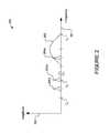
- FIG. 1shows an overview of a photovoltaic energy system including local management units (LMUs) according to one embodiment.
- LMUslocal management units
- FIG. 2shows a graph of the relationships of frequency vs. amplitude (with an amplitude axis and a frequency axis) for exemplary communication channels of a local management unit (LMU) according to one embodiment.
- LMUlocal management unit
- FIG. 3is a flowchart illustrating a process for implementation of a communication protocol in an LMU according to one embodiment.
- FIG. 4is a circuit diagram illustrating a local controller or LMU according to one embodiment.
- FIG. 5is a circuit diagram illustrating an LMU providing two connectors for serial connections with other LMUs to form a serial power bus according to one embodiment.
- FIG. 6is a block diagram illustrating an overview of a computer system that may be used for one or more components of the system of FIG. 1 according to various embodiments.
- a “solar cell”is a photovoltaic device configured to absorb photons and convert them into electrical energy.
- a “solar module”is a device that includes at least one or more solar cells, wherein the solar cells are connected in series or in parallel.
- a solar panelis one example of a solar module. The solar cells absorb photons and convert the photons into electrical energy.
- a power busmay be a conductive path connecting one or more solar modules in series.
- At least some embodiments of the disclosureprovide a system and method for the operation of distributed local management units (LMUs) in a photovoltaic energy system.
- LMUsdistributed local management units
- each LMUattempts to communicate on a first active channel with a master management unit.
- Each LMUis coupled to control one solar module of a plurality of solar modules in the system. If the communication with the master management unit on the first active channel has been established, then the LMU proceeds to a configuration process. If the communication on the first active channel is not established (i.e., fails for some reason), the LMU attempts to communicate on a second active channel.
- the second active channelhas a frequency different from the first active channel. If communication with the master management unit on the second active channel is established, then the LMU proceeds to the configuration process. If communication is not established after a predetermined total number of attempts or attempts on a predetermined number of channels, then the LMU proceeds to an error handling process.
- FIG. 1shows an overview of an exemplary system 100 according to one embodiment.
- System 100contains two exemplary strings of solar panels, namely string 110 a - n and string 120 a - n .
- Each solar panel in each stringhas its own local management unit (e.g., a local controller or a data processing system), which, in this exemplary illustration, are units 111 a - n and 121 a - n , respective to the strings named above.
- the LMUs in FIG. 1are connected in series (i.e., in a serial configuration) to power busses 150 and 160 .
- Each local management unithas an antenna; in this exemplary illustration, only antennas 112 a and 122 a are numbered in FIG. 1 , for simplicity and clarity of illustration.
- Combiner box 102is typically used to combine the output of said multiple strings (i.e., 110 a - n and 120 a - n ) of panels.
- Power busses 150 and 160are connected to combiner box 102 .
- combiner box 102may be used to house the wires, connections, etc., to combine the electricity generated from different solar panels, strings, subsystems, etc.
- Combiner box 102is coupled to an inverter 101 , for example, connected to power grid 103 .
- Master management unit (MMU) 130(e.g., a master controller) is coupled to control each of the LMUs (e.g., by wireless communication via antennas 112 a and 122 a .
- MMU 130acts as a gateway, connecting, for example, to the Internet 140 , via connection 131 , which may be wired, land line, Ethernet, wireless, or any other of various types of suitable connection.
- MMU 130may store configuration profiles in a local database.
- MMU 130may be updated or operated remotely from a remote server. For example, new profiles may be downloaded to MMU 130 using Internet 140 .
- MMU 130has an antenna 132 , which is used to communicate with the distributed LMUs.
- one of the LMUsmay act as the MMU for the system.
- the master management unit 130is typically powered by the solar panels. However, it may be powered by alternative power sources, such as power grid 103 .
- Power line 133may supply power to MMU 130 , and in some cases, it could also transmit communications via power line communication between the MMU and LMUs, instead of using wireless communication.
- power line communicationmay exhibit problems similar to wireless communication, such as radio frequency (RF) interferences and other effects that may benefit from the use of active channel selection as described below.
- RFradio frequency
- One example of power line communicationis discussed in U.S. Non-Provisional Application Ser. No. 12/467,117, filed May 15, 2009, entitled “METHOD AND SYSTEM FOR CURRENT-MODE POWER LINE COMMUNICATIONS,” by Leonid Rozenboim, the entire contents of which application is incorporated by reference as if fully set forth herein.
- FIG. 1The structure as shown in FIG. 1 is one specific type of configuration, but other configurations may be used in other embodiments.
- other system configurationsmay be as follows: 1) a set of solar panels, each connected to a parallel bus via a local management unit; 2) similarly as in FIG. 1 , but with each string further connected to a parallel bus via a string management unit.
- the operating protocol for the LMUs as described hereinmay be used with either a serial configuration (i.e., strings of local management units) or a parallel configuration (i.e., local management units on a parallel bus).
- an LMUmay be provided for each solar panel, so that when the solar panels are connected into a system via the LMUs, the efficiency of the system as a whole is increased.
- the LMUsare designed to keep each solar panel working at, or close to, its respective maximum power point, substantially independently from each other, even through the panels are connected together to form a system.
- the LMUsmay also be configured to provide various features, such as safety, panel protection, etc., in various implementations.
- strings of LMUs connected in serialmay be each connected to a string management unit for parallel combinations of strings at a combiner box.
- the power output level of a solar panelis based on the voltage or current consumed by its load.
- a given working conditione.g., sunlight exposure, temperature, etc.
- the power output level of a solar panelis based on the voltage or current consumed by its load.
- the LMUspermit individual solar panels to work at their maximum power points, while adjusting LMU outputs for efficient operations in serial or parallel connections.
- the solar panelsare connected in parallel to a high voltage DC bus via their LMUs; and the DC bus can be used to power an inverter, which is tied to a power grid, to supply the grid.
- the solar panelsare connected in series via their LMUs; and the string of the solar panels (a serial power bus) can be used to power an inverter, which is tied to a power grid, to supply the grid.
- LMUsmay have the following features:
- LMUs for parallel connectionsare used to boost voltage (V out >V mp ).
- Each parallel LMUhas a step up converter and has a maximum power point tracking circuit.
- Parallel LMUsare configured to output a substantially fixed voltage, allowing only very small variations from the nominal voltage of the high voltage DC bus.
- LMUs for series connectionstypically boost current (I out >I mp ).
- the serial LMUsdo not use step up converters or maximum power point tracking circuits.
- Serial LMUsreceive duty cycles from a system management unit (e.g., master management unit 130 ), which coordinates the output of the serial LMUs to improve the performance of the system.
- the system management unitadjusts the duty cycles of the serial LMUs to adjust the states of their respective solar panels.
- a solar panelhas a few strings of solar cells (e.g., three solar cell strings per module).
- a local management unitcan be applied to a group of cells within a string of an individual solar panel, or in some cases to each cell in a solar panel.
- a group of solar cells that are attached to a local management unitmay be connected to each other in series, in parallel, or in a mesh configuration.
- a number of local management unitsconnect the groups of the solar cells in a string to provide output for the solar panel.
- Some embodiments of the disclosureinclude methods to determine the duty cycles and/or phases for local management units connected to a string or mesh of solar modules.
- the system management unitcontrols the operations of the LMUs via a communication connection, which may be over the power line through which the solar panels deliver power, or over wireless connections, or via separate communication lines (e.g., as discussed above for FIG. 1 ).
- each LMUmay have a watchdog circuit, which cuts off its output if the heartbeat signal from the system management unit is missing. This allows the solar system to be completely shut down remotely (e.g., for fire-fighting, or cleaning, etc.).
- the MMUlistens for new LMUs that may be attempting to communicate with the MMU, for example during set up of a new system, or during replacement of an LMU.
- the MMUmay listen on certain predefined channels (e.g., selected communication frequencies) known to the LMU. After the LMU establishes communication with the MMU, the LMU restarts and again establishes communication with the MMU, but does so on a different channel different from these predefined channels.
- a remote server or other computer systemmay be used to provide configuration profiles to the MMU (e.g., over the Internet). This permits a local photovoltaic system to be configured remotely by providing updated profiles to the MMU, then restarting one or more LMUs using the new profiles.
- a plurality of local management unitsare configured to, under supervision of a master management unit, balance currents between the plurality of solar modules in the power bus.
- the LMUsmay be configured to balance voltages and currents between solar modules and between power buses.
- the LMUscan be implemented serially or in parallel.
- FIG. 2shows a graph 200 of the relationships of frequency vs. amplitude, with amplitude axis 202 and frequency axis 201 in one embodiment.
- FIG. 2illustrates exemplary communication channels used by an LMU to communicate with the MMU. Shown on frequency axis 201 are a number of channels f 0 -f z , with channel f n , being the actual active channel in use. Also shown are exemplary signals 204 a , 204 b , and 204 x corresponding to communication on these channels. In this example, a number of channels are covered by a disturbing interference 203 (e.g., interference from a microwave nearby). This interference may cause communications with the MMU to fail, and thus require the use of an alternate active channel.
- a disturbing interference 203e.g., interference from a microwave nearby. This interference may cause communications with the MMU to fail, and thus require the use of an alternate active channel.
- FIG. 3shows an exemplary process 300 in one embodiment for implementation of a communications protocol in an LMU. More specifically, FIG. 3 illustrates a protocol for an LMU to communicate with an MMU in one embodiment. In one embodiment, the protocol supports the automatic self-configuration of the LMU.
- step 301the LMU unit wakes up.
- step 302the system checks to determine whether it has a predefined profile list of starting values (e.g., the output voltage for the solar panel controlled by the LMU; or power level and/or initial channel to use for communications). If not (No), in step 303 , the system sets a maximum value (e.g., maximum communications power or a default active channel). The maximum value may typically be for the output voltage that particular LMU contributes to its string, except in cases where local regulations require that the value be set lower than the maximum.
- step 304the system sets the LMU at the preset value(s). Once the value is set for LMU operation in either step 303 or step 304 , communication is attempted with the MMU on a first active channel. In step 305 , the system checks to determine whether communication with the MMU has been established.
- step 306the system communicates with the MMU in step 306 and in step 307 , it receives one or more instructions from the MMU.
- step 308the system executes the instruction(s) it has received.
- step 309the system waits for a period (e.g., 1-5 seconds) whose value is contained in its profile list, and then it repeats the communication loop beginning again at step 306 .
- step 306the system moves to step 315 and commences an error treatment protocol, for example as described below or otherwise.
- errorsmay include detection of a non-existing command, a mismatch in the MMU identification number, etc.
- step 310the system attempts to establish communication by setting the channel f n to the frequency of initial active channel f 0 and, in step 311 , scanning f n .
- step 312the system checks to see if communication is then established on this new active channel. If it is (Yes), the system continues to the sequence of steps starting with step 306 , as described above. If, in step 312 , communication is not established (No), in step 313 the system increments the then-active channel f n to the next available channel f 0 +1 (i.e., channel f 1 ).
- step 314the system checks to see if the next incremental channel exceeds the maximum number of available channels (e.g., a predetermined maximum number of channels stored in the LMU start-up profile). If the maximum is not exceeded (No), the system returns to step 311 and continues to scan succeeding active channels until either it establishes communication or it exceeds the maximum number of channels. In the case of exceeding the maximum number of available channels in step 314 (Yes), the system moves to step 315 and commences an error treatment protocol.
- An error treatment protocolmay include one or more of various approaches. One typical approach would reset the LMU and start again at step 301 . Another approach would shut down the LMU; while yet another would loop back to step 305 and try again.
- the section below entitled “EXEMPLARY PROTOCOL COMMUNICATION INFORMATION”shows specific examples of the protocol of communications between an exemplary distributed LMU and an exemplary MMU. This protocol shows how a system can self-detect elements, available channels, etc., thus reducing setup efforts. This is advantageous with the use of wireless communications, as channels may be blocked by outside sources of interference (e.g., as discussed for FIG. 2 above), and the system desirably should be able to self-reconfigure in such situations.
- FIG. 4shows an exemplary local controller or LMU 400 according to one embodiment.
- Wires 420 a,bare connected to a solar panel 110 or 120 (i.e., to provide incoming electricity).
- Wires 421 a,bare used to chain the LMUs together to form a string, as in the serial configuration illustrated in FIG. 1 .
- the hardware of LMU 400is configured for use in such a serial connection.
- Core LMU 401has switches 403 , 404 and 406 , plus controller 402 .
- a diode 405provides a voltage drop in the case of a short of switch 404 , to ensure enough voltage to operate controller 402 .
- Modem 407 and/or wireless network interface 408are coupled to controller 402 to permit communications with the LMUs.
- modem 407connects to the string wiring 421 a,b (e.g., to modulate control signals onto the wiring 421 a,b at control frequencies higher than the normal operating frequencies used in power busses 150 and 160 ).
- wireless network interface 408has an antenna 410 to use for communications with the LMUs.
- the network communications type usedmay be one of many different types of conventional wireless networks.
- the use of wireless communicationmay be advantageous in some cases by reducing the number of hardwire points of failure, and thus increasing the simplicity of system setup or the reliability of system operation.
- an LMUdoes not have both a modem 407 and a wireless network interface 408 .
- a systemcontains only one or the other, but in some cases, these may be, for example, plug-in modules. In other cases, both components may be present, but only one may be activated.
- Controller 402may be configured for operation by additional software code 409 that may include, in addition to other previously discussed features for a communication protocol, code for implementing a shut-off system.
- Local management unit 501provides two connectors 512 and 515 for serial connections with other local management units 501 to form a serial power bus (e.g., power bus 150 or 160 of FIG. 1 ). Note that in other embodiments, a parallel configuration of LMUs may be used.
- a controller 509controls the states of switches Q 1 506 and Q 2 508 .
- the controller 509turns on switch 506 , the panel voltage and the capacitor C 1 505 are connected in parallel to the connectors 512 and 515 .
- the output voltage between the connectors 512 and 515is substantially the same as the output panel voltage.
- the controller 509turns on (closes) the switch Q 2 508 to provide a path around the diode D 1 507 to improve efficiency.
- the panel voltagecharges the capacitor C 1 505 , such that when the switch 506 is turned on, both the solar panel and the capacitor 505 provides currents going through the connectors 512 and 515 , allowing a current larger than the current of the solar panel to flow in the string (e.g., the serial power bus 150 or 160 of FIG. 1 ).
- the diode D 1 507also provides a path between the connectors 512 and 515 to sustain the current in the string, even if the switch 508 is off for some reason.
- the controller 509is connected (not shown) to the panel voltage to obtain the power for controlling the switches Q 1 506 and Q 2 508 .
- the controller 509is further connected (not shown) to at least one of the connectors 512 and 515 to transmit and/or receive information from the string.
- the controller 509includes sensors (not shown) to measure operating parameters of the solar panel, such as panel voltage, panel current, temperature, light intensity, etc.
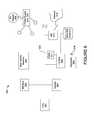
- FIG. 6shows an exemplary overview of a computer or data processing system 600 as may be used, in some embodiments, at various locations (e.g., for use as an MMU or an LMU) throughout system 100 . It is generally exemplary of any computer that may execute code to process data. Various modifications and changes may be made to computer system 600 without departing from the broader spirit and scope of the system and method disclosed herein. For example, in various embodiments, computer system 600 may be used to implement processes, protocols, or methods described herein. For example, an MMU may be implemented via computer system 600 . In other embodiments, LMUs are implemented via controllers, rather than use of a full computer system.
- CPU 601is connected to bus 602 , to which bus is also connected memory 603 , non-volatile memory 604 , display 607 , I/O unit 608 , and network interface card (NIC) 613 .
- I/O unit 608may, typically, be connected to keyboard 609 , pointing device 610 , hard disk 612 , and real-time clock 611 .
- NIC 613connects to network 614 , which may be the Internet or a local network, which local network may or may not have connections to the Internet.
- power supply unit 605connected, in this example, to AC supply 606 .
- FIG. 6illustrates various components of a computer system, it is not intended to represent any particular architecture or manner of interconnecting the components. Other systems that have fewer or more components may also be used.
- typical I/O devicesmay include mice, modems, network interfaces, printers, scanners, video cameras and other devices which are well known in the art.
- the bus 602may include one or more buses connected to one another through various bridges, controllers and/or adapters.
- the I/O unit 608includes a USB (Universal Serial Bus) adapter for controlling USB peripherals, and/or an IEEE-1394 bus adapter for controlling IEEE-1394 peripherals.
- USBUniversal Serial Bus
- memorymay include ROM (Read Only Memory) and volatile RAM (Random Access Memory).
- Non-volatile memorymay include, for example, a hard drive, flash memory, etc.
- Volatile RAMis typically implemented as dynamic RAM (DRAM) which requires power continually in order to refresh or maintain the data in the memory.
- Non-volatile memoryis typically a magnetic hard drive, a magnetic optical drive, or an optical drive (e.g., a DVD RAM), or other type of memory system which maintains data even after power is removed from the system.
- the non-volatile memorymay also be a random access memory.
- the non-volatile memorycan be a local device coupled directly to the rest of the components in the data processing system.
- a non-volatile memory that is remote from the systemsuch as a network storage device coupled to the data processing system through a network interface such as a modem or Ethernet interface, can also be used.
- one or more servers of the systemcan be replaced with the service of a peer to peer network of a plurality of data processing systems, or a network of distributed computing systems.
- the peer to peer network, or a distributed computing systemcan be collectively viewed as a server data processing system.
- Embodiments of the disclosurecan be implemented via the processor(s) 601 and/or the memory 603 / 604 .
- the functionalities describedcan be partially implemented via hardware logic in the processor(s) 601 and partially using the instructions stored in the memory 603 and/or 604 .
- Some embodimentsare implemented using the processor(s) 601 without additional instructions stored in memory.
- Some embodimentsare implemented using the instructions stored in the memory for execution by one or more general purpose microprocessor(s).
- the disclosureis not limited to a specific configuration of hardware and/or software.
- communicationsare attempted using this exemplary communication protocol, from a first local management, on a first active channel with the MMU.
- communicationis attempted on a second active channel with the MMU, the second active channel having a frequency different from the first active channel.
- the methodfurther comprises after the communication on the second active channel has been established, receiving a first communication from the master management unit.
- the first communicationcomprises an instruction (e.g., a command), and the method further comprises executing the instruction on the first local management unit.
- the plurality of local management unitsare connected in series. In another embodiment, the plurality of local management units are connected in parallel.
- the communication on the first active channelis at a predetermined frequency used by the master management unit for establishing communication with new local management units being added to the system.
- the methodfurther comprises after communication with the master management unit has been established, restarting the first local management unit and subsequently communicating with the master management unit at a frequency other than the predetermined frequency.
- the methodfurther comprises communicating from the first local management unit to the master management unit an identification code (e.g., Unit ID) associated with the first local management unit; and receiving a profile from the master management unit, the profile corresponding to the identification code.
- the methodfurther comprises in response to receiving the identification code, retrieving, via the master management unit, the profile from a database that includes a plurality of different profiles suitable for configuration of local management units.
- the first local management unitcomprises an antenna
- the attempting to communicate on the first active channelcomprises sending a wireless signal via the antenna.
- the methodfurther comprises after the communication on the second active channel has been established, determining that an error has occurred in communication with the master management unit; and in response to the error, initiating an error treatment protocol for the first local management unit.
- the methodfurther comprises: in response to a determination that the communication on the second active channel has not been established, attempting to communicate on a third active channel with the master management unit, the third active channel having a frequency different from the first and second active channels; determining if communication with the master management unit on the third active channel has been established; in response to a determination that the communication on the third active channel has not been established, determining whether a predetermined number of available channels for communication with the master management unit has been exceeded; and in response to a determination that the predetermined number has been exceeded, initiating an error treatment protocol for the first local management unit.
- the methodfurther comprises: prior to the attempting to communicate on the first active channel, waking up the first local management unit; after the waking up, determining whether the first local management unit is storing a configuration profile; in response to a determination that the first local management unit is not storing the configuration profile, communicating to the master management unit a first identification code associated with the first local management unit; receiving a first profile from the master management unit, the first profile corresponding to the first identification code, and the first profile including a time period; and configuring the first local management unit using the first profile.
- the methodfurther comprises: after the communication on the second active channel has been established, receiving a first instruction from the master management unit; executing the first instruction on the first local management unit; after the executing the first instruction, waiting for the time period; after the waiting, communicating with the master management unit to receive a second instruction; and executing the second instruction on the first local management unit.
- the methodfurther comprises: establishing communication with the master management unit from a second local management unit of the plurality of local management units; and communicating to the master management unit a second identification code associated with the second local management unit; receiving a second profile from the master management unit, the second profile corresponding to the second identification code; and configuring the second local management unit using the second profile.
- a local management unitcomprises memory storing software instructions, and a controller coupled to the memory.
- the controlleris configured via the software instructions to execute a method comprising: controlling, under supervision by a master management unit, a first solar module of a plurality of solar modules, the master management unit coupled to supervise a plurality of local management units, wherein the plurality of local management units are coupled by a power bus, and each one of the plurality of local management units controls a respective one of the plurality of solar modules, attempting to communicate on a first active channel with the master management unit, determining if communication with the master management unit on the first active channel has been established, in response to a determination that the communication on the first active channel has not been established, attempting to communicate on a second active channel with the master management unit, the second active channel having a frequency different from the first active channel, and determining if communication with the master management unit on the second active channel has been established.
- systemfurther comprises a modem or wireless network interface to attempt to communicate with the master management unit on the first active channel.
- the plurality of local management unitsare configured to, under supervision of the master management unit, balance currents between the plurality of solar modules in the power bus.
- a non-transitory computer-readable storage mediumtangibly stores computer readable instructions.
- the instructionscause a computer or data processing system to perform a method comprising: attempting to communicate, from a first local management unit of a plurality of local management units, on a first active channel with a master management unit, each of the plurality of local management units coupled to control a respective solar module of a plurality of solar modules; determining if communication with the master management unit on the first active channel has been established; in response to a determination that the communication on the first active channel has not been established, attempting to communicate on a second active channel with the master management unit, the second active channel having a frequency different from the first active channel; and determining if communication with the master management unit on the second active channel has been established.
- methodfurther comprises: communicating from the first local management unit to the master management unit an identification code associated with the first local management unit; and receiving a profile from the master management unit, the profile corresponding to the identification code.
- various functions and operationsmay be described as being performed by or caused by software code to simplify description. However, those skilled in the art will recognize what is meant by such expressions is that the functions result from execution of the code by a processor, such as a microprocessor.
- the functions and operationscan be implemented using special purpose circuitry, with or without software instructions, such as using an Application-Specific Integrated Circuit (ASIC) or a Field-Programmable Gate Array (FPGA).
- ASICApplication-Specific Integrated Circuit
- FPGAField-Programmable Gate Array
- Embodimentscan be implemented using hardwired circuitry without software instructions, or in combination with software instructions. Thus, the techniques are limited neither to any specific combination of hardware circuitry and software, nor to any particular source for the instructions executed by the data processing system.
- At least some aspects disclosedcan be embodied, at least in part, in software. That is, the techniques may be carried out in a computer system or other data processing system in response to its processor, such as a microprocessor, executing sequences of instructions contained in a memory, such as ROM, volatile RAM, non-volatile memory, cache or a remote storage device.
- processorsuch as a microprocessor
- a memorysuch as ROM, volatile RAM, non-volatile memory, cache or a remote storage device.
- Routines executed to implement the embodimentsmay be implemented as part of an operating system, middleware, service delivery platform, SDK (Software Development Kit) component, web services, or other specific application, component, program, object, module or sequence of instructions referred to as “computer programs.” Invocation interfaces to these routines can be exposed to a software development community as an API (Application Programming Interface).
- the computer programstypically comprise one or more instructions set at various times in various memory and storage devices in a computer, and that, when read and executed by one or more processors in a computer, cause the computer to perform operations necessary to execute elements involving the various aspects.
- a machine readable mediumcan be used to store software and data which when executed by a data processing system causes the system to perform various methods.
- the executable software and datamay be stored in various places including for example ROM, volatile RAM, non-volatile memory and/or cache. Portions of this software and/or data may be stored in any one of these storage devices.
- the data and instructionscan be obtained from centralized servers or peer to peer networks. Different portions of the data and instructions can be obtained from different centralized servers and/or peer to peer networks at different times and in different communication sessions or in a same communication session.
- the data and instructionscan be obtained in entirety prior to the execution of the applications. Alternatively, portions of the data and instructions can be obtained dynamically, just in time, when needed for execution. Thus, it is not required that the data and instructions be on a machine readable medium in entirety at a particular instance of time.
- Examples of computer-readable mediainclude but are not limited to recordable and non-recordable type media such as volatile and non-volatile memory devices, read only memory (ROM), random access memory (RAM), flash memory devices, floppy and other removable disks, magnetic disk storage media, optical storage media (e.g., Compact Disk Read-Only Memory (CD ROMS), Digital Versatile Disks (DVDs), etc.), among others.
- recordable and non-recordable type mediasuch as volatile and non-volatile memory devices, read only memory (ROM), random access memory (RAM), flash memory devices, floppy and other removable disks, magnetic disk storage media, optical storage media (e.g., Compact Disk Read-Only Memory (CD ROMS), Digital Versatile Disks (DVDs), etc.), among others.
- a machine readable mediumincludes any mechanism that provides (e.g., stores) information in a form accessible by a machine (e.g., a computer, network device, personal digital assistant, manufacturing tool, any device with a set of one or more processors, etc.).
- a machinee.g., a computer, network device, personal digital assistant, manufacturing tool, any device with a set of one or more processors, etc.
- hardwired circuitrymay be used in combination with software instructions to implement the techniques.
- the techniquesare neither limited to any specific combination of hardware circuitry and software nor to any particular source for the instructions executed by the data processing system.
- Gatewayis radio is then forcibly restarted with a hammer.
- the gateway implementationdoes not finish the answer packet before resetting.
Landscapes
- Engineering & Computer Science (AREA)
- Computer Networks & Wireless Communication (AREA)
- Signal Processing (AREA)
- Health & Medical Sciences (AREA)
- Computing Systems (AREA)
- General Health & Medical Sciences (AREA)
- Medical Informatics (AREA)
- Charge And Discharge Circuits For Batteries Or The Like (AREA)
Abstract
Description
- <command>=0x02
- <body>=<line count> <seq ID>
- <line count>Number of lines desired
- 16 bits, high byte first
- <seq ID>Starting sequence number desired
- <32 bits, high byte first
- Responses
- 0x03—data response
- 0x05—no data response
(0x03) Data Response
- <response>=0x03
- <body>=<line count> <delimiter> <LMU line> . . .
- <line count>Count of available lines
- 16 bits, high byte first
- <delimiter>0xDDDD
- 16 bites, high byte first
- <LMU line>= . . .
(0x04) Get NO data request
- <command>=0x04
- <body>=<empty>
- Responses
- 0x05—no data response
(0x05) No Data Response
- 0x05—no data response
- <response>=0x05
- <body>=<Seq ID first> <Seq ID next>
- <Seq ID first> First available Seq ID
- 32 bits, high byte first
- <Seq ID next>“Current” Seq ID (highest+1)
- 32 bits, high byte first
(0x06) General parameter error response
- 32 bits, high byte first
- <response>=0x06
- <body>=<empty>
(0x08) Send Broadcast Request
- <command>=0x08
- <body>=<ascii bytes>
- <ascii bytes>Up to 40 ascii bytes . . .
- Responses
- 0x09—send broadcast response
(0x09) Send Broadcast Response
- 0x09—send broadcast response
- <command>=0x09
- <body>=<empty>
(0x0a) Send Version Request
- <command>=0x0a
- <body>=<empty>
- Responses
- 0x0b—Send Version Response
(0x0b) Send Version Response
- 0x0b—Send Version Response
- <response>=0x0b
- <body>=<version string><build date><build time>
- <version string>Delimited ascii string (CR delimiter)
- Typ: “Gateway Version 00.6a”
- <build date>Delimited ascii string (CR delimiter)
- Typ: “Build Aug 24 2009”
- <build time>Delimited ascii string (CR delimiter)
- Typ: “10:00:38”
(0x0c) Set Channel Request
- Typ: “10:00:38”
- <command>=0x0c
- <body>=<desired channel>
- <desired channel>Channel number between 11 and 26 (dec)
- 16 bit, high byte first
- Responses
- 0x06—Bad parameter response
- 0x0d—Set Channel Response
(0x0d) Set Channel Response
- <response>=0x0d
- <body>=<empty>
(0x0e) Get Channel Request - <command>=0x0e
- <body>=<empty>
- <current channel>Channel number between 11 and 26 (dec)
- 16 bit, high byte first
- Responses
- 0x0d—Get Channel Response
(0x0f) Set Channel Response
- 0x0d—Get Channel Response
- <response>=0x0d
- <body>=<current channel>
- <current channel>Channel number between 11 and 26 (dec)
- 16 bit, high byte first
(0x10) Request Gateway Reset
- 16 bit, high byte first
- <command>=0x10
- <body>=<magic string>
- <magic string>0x37249266L-arbitrary . . .
- 32 bit, high byte first
- Responses
- 0x06—General error response (bad magic number)
- 0x11—Get reset request Response
(0x11) Request Gateway Reset Response
- <response>=0x11
- <body>=<empty>
- <command>=0x12
- <body>=<magic string>
- <magic string>0x37249266L-arbitrary . . .
- 32 bit, high byte first
- Responses
- 0x06—General error response (bad magic number)
- 0x13—STORE settings response
(0x13) STORE settings response
- <command>=0x13
- <body>=<empty>
(0x14) Set Unit ID Request
- <command>=0x14
- <body>=<magic number> <desired ID>
- <magic string>ox37249266L-arbitrary . . .
- 32 bit, high byte first
- <desired id>Desired Unit ID
- 16 bit, high byte first
- Responses
- 0x06—Bad parameter response
- 0x15—Set Unit ID Response
(0x15) Set Channel Response
- <response>=0x15
- <body> =<empty>
(0x16) Get Unit ID Request - <command>=0x16
- <body>=<empty>
- Responses
- 0x0d—Get Channel Response
(0x17) Get Unit ID Response
- 0x0d—Get Channel Response
- <response>=0x17
- <body>=<current channel>
- <current ID>Unit ID
- 16 bit, high byte first
B. Packet Level
(MMU to Gateway):
<0x55> <0x55> <length> <Gateway ID> <command> <body> <checksum>
- 16 bit, high byte first
- <0x55> literal header bytes
- <length>length—count of bytes starting with gateway ID
- through checksum. Total length minus 4
- 16 bits, high byte first
- <Gateway ID> Gateway address−test=0x1235
- 16 bits, high byte first
- <command> Command to execute
- 16 bits, high byte first
(Gateway to MMU):
<0xAA> <0xAA> <length> <Gateway ID> <command> <body> <checksum>
- 16 bits, high byte first
- <0xAA> literal header bytes
- <length> length—count of bytes starting with gateway ID through checksum. Total length minus 4
- 16 bits, high byte first
- <Gateway ID> Gateway address−test=0x1235
- 16 bits, high byte first
- <command> Command response
- 16 bits, high byte first
Claims (19)
Priority Applications (9)
| Application Number | Priority Date | Filing Date | Title |
|---|---|---|---|
| US12/895,745US8773236B2 (en) | 2009-12-29 | 2010-09-30 | Systems and methods for a communication protocol between a local controller and a master controller |
| US13/073,915US8854193B2 (en) | 2009-12-29 | 2011-03-28 | Systems and methods for remote or local shut-off of a photovoltaic system |
| US13/092,099US9007210B2 (en) | 2010-04-22 | 2011-04-21 | Enhanced system and method for theft prevention in a solar power array during nonoperative periods |
| US14/503,723US9377765B2 (en) | 2009-12-29 | 2014-10-01 | Systems and methods for remote or local shut-off of a photovoltaic system |
| US15/186,330US10063056B2 (en) | 2009-12-29 | 2016-06-17 | Systems and methods for remote or local shut-off of a photovoltaic system |
| US16/055,789US10523013B2 (en) | 2009-12-29 | 2018-08-06 | Systems and methods for remote or local shut-off of a photovoltaic system |
| US16/729,100US11081889B2 (en) | 2009-12-29 | 2019-12-27 | Systems and methods for remote or local shut-off of a photovoltaic system |
| US17/351,071US11728443B2 (en) | 2009-12-29 | 2021-06-17 | Systems and methods for remote or local shut-off of a photovoltaic system |
| US18/361,580US12433063B2 (en) | 2009-12-29 | 2023-07-28 | Systems and methods for remote or local shut-off of a photovoltaic system |
Applications Claiming Priority (2)
| Application Number | Priority Date | Filing Date | Title |
|---|---|---|---|
| US33500409P | 2009-12-29 | 2009-12-29 | |
| US12/895,745US8773236B2 (en) | 2009-12-29 | 2010-09-30 | Systems and methods for a communication protocol between a local controller and a master controller |
Related Parent Applications (1)
| Application Number | Title | Priority Date | Filing Date |
|---|---|---|---|
| US12/985,883Continuation-In-PartUS8271599B2 (en) | 2010-01-08 | 2011-01-06 | Systems and methods for an identification protocol between a local controller and a master controller in a photovoltaic power generation system |
Related Child Applications (2)
| Application Number | Title | Priority Date | Filing Date |
|---|---|---|---|
| US13/073,915Continuation-In-PartUS8854193B2 (en) | 2009-12-29 | 2011-03-28 | Systems and methods for remote or local shut-off of a photovoltaic system |
| US13/092,099Continuation-In-PartUS9007210B2 (en) | 2010-04-22 | 2011-04-21 | Enhanced system and method for theft prevention in a solar power array during nonoperative periods |
Publications (2)
| Publication Number | Publication Date |
|---|---|
| US20110161722A1 US20110161722A1 (en) | 2011-06-30 |
| US8773236B2true US8773236B2 (en) | 2014-07-08 |
Family
ID=44188946
Family Applications (1)
| Application Number | Title | Priority Date | Filing Date |
|---|---|---|---|
| US12/895,745Active2033-02-13US8773236B2 (en) | 2009-12-29 | 2010-09-30 | Systems and methods for a communication protocol between a local controller and a master controller |
Country Status (1)
| Country | Link |
|---|---|
| US (1) | US8773236B2 (en) |
Cited By (63)
| Publication number | Priority date | Publication date | Assignee | Title |
|---|---|---|---|---|
| US9007210B2 (en) | 2010-04-22 | 2015-04-14 | Tigo Energy, Inc. | Enhanced system and method for theft prevention in a solar power array during nonoperative periods |
| US9088178B2 (en) | 2006-12-06 | 2015-07-21 | Solaredge Technologies Ltd | Distributed power harvesting systems using DC power sources |
| US9112379B2 (en) | 2006-12-06 | 2015-08-18 | Solaredge Technologies Ltd. | Pairing of components in a direct current distributed power generation system |
| US9124139B2 (en) | 2010-01-08 | 2015-09-01 | Tigo Energy, Inc. | Systems and methods for an identification protocol between a local controller coupled to control a solar module and a master controller |
| US9130401B2 (en) | 2006-12-06 | 2015-09-08 | Solaredge Technologies Ltd. | Distributed power harvesting systems using DC power sources |
| US20150357821A1 (en)* | 2011-07-28 | 2015-12-10 | Tigo Energy, Inc. | Systems and methods to combine strings of solar panels |
| US9235228B2 (en) | 2012-03-05 | 2016-01-12 | Solaredge Technologies Ltd. | Direct current link circuit |
| US9291696B2 (en) | 2007-12-05 | 2016-03-22 | Solaredge Technologies Ltd. | Photovoltaic system power tracking method |
| US9318974B2 (en) | 2014-03-26 | 2016-04-19 | Solaredge Technologies Ltd. | Multi-level inverter with flying capacitor topology |
| US9362743B2 (en) | 2008-05-05 | 2016-06-07 | Solaredge Technologies Ltd. | Direct current power combiner |
| US9368964B2 (en) | 2006-12-06 | 2016-06-14 | Solaredge Technologies Ltd. | Distributed power system using direct current power sources |
| US9401599B2 (en) | 2010-12-09 | 2016-07-26 | Solaredge Technologies Ltd. | Disconnection of a string carrying direct current power |
| US9407161B2 (en) | 2007-12-05 | 2016-08-02 | Solaredge Technologies Ltd. | Parallel connected inverters |
| US9537445B2 (en) | 2008-12-04 | 2017-01-03 | Solaredge Technologies Ltd. | Testing of a photovoltaic panel |
| US9543889B2 (en) | 2006-12-06 | 2017-01-10 | Solaredge Technologies Ltd. | Distributed power harvesting systems using DC power sources |
| US9548619B2 (en) | 2013-03-14 | 2017-01-17 | Solaredge Technologies Ltd. | Method and apparatus for storing and depleting energy |
| US9590526B2 (en) | 2006-12-06 | 2017-03-07 | Solaredge Technologies Ltd. | Safety mechanisms, wake up and shutdown methods in distributed power installations |
| US9647442B2 (en) | 2010-11-09 | 2017-05-09 | Solaredge Technologies Ltd. | Arc detection and prevention in a power generation system |
| US9644993B2 (en) | 2006-12-06 | 2017-05-09 | Solaredge Technologies Ltd. | Monitoring of distributed power harvesting systems using DC power sources |
| US9673711B2 (en) | 2007-08-06 | 2017-06-06 | Solaredge Technologies Ltd. | Digital average input current control in power converter |
| US9680304B2 (en) | 2006-12-06 | 2017-06-13 | Solaredge Technologies Ltd. | Method for distributed power harvesting using DC power sources |
| US9812984B2 (en) | 2012-01-30 | 2017-11-07 | Solaredge Technologies Ltd. | Maximizing power in a photovoltaic distributed power system |
| US9819178B2 (en) | 2013-03-15 | 2017-11-14 | Solaredge Technologies Ltd. | Bypass mechanism |
| US9831824B2 (en) | 2007-12-05 | 2017-11-28 | SolareEdge Technologies Ltd. | Current sensing on a MOSFET |
| US9853538B2 (en) | 2007-12-04 | 2017-12-26 | Solaredge Technologies Ltd. | Distributed power harvesting systems using DC power sources |
| US9853565B2 (en) | 2012-01-30 | 2017-12-26 | Solaredge Technologies Ltd. | Maximized power in a photovoltaic distributed power system |
| US9866098B2 (en) | 2011-01-12 | 2018-01-09 | Solaredge Technologies Ltd. | Serially connected inverters |
| US9869701B2 (en) | 2009-05-26 | 2018-01-16 | Solaredge Technologies Ltd. | Theft detection and prevention in a power generation system |
| US9876430B2 (en) | 2008-03-24 | 2018-01-23 | Solaredge Technologies Ltd. | Zero voltage switching |
| US9923516B2 (en) | 2012-01-30 | 2018-03-20 | Solaredge Technologies Ltd. | Photovoltaic panel circuitry |
| US9941813B2 (en) | 2013-03-14 | 2018-04-10 | Solaredge Technologies Ltd. | High frequency multi-level inverter |
| US9960667B2 (en) | 2006-12-06 | 2018-05-01 | Solaredge Technologies Ltd. | System and method for protection during inverter shutdown in distributed power installations |
| US9966766B2 (en) | 2006-12-06 | 2018-05-08 | Solaredge Technologies Ltd. | Battery power delivery module |
| US10097108B2 (en) | 2014-12-16 | 2018-10-09 | Abb Schweiz Ag | Energy panel arrangement power dissipation |
| US10115841B2 (en) | 2012-06-04 | 2018-10-30 | Solaredge Technologies Ltd. | Integrated photovoltaic panel circuitry |
| US10218307B2 (en) | 2014-12-02 | 2019-02-26 | Tigo Energy, Inc. | Solar panel junction boxes having integrated function modules |
| US10230310B2 (en) | 2016-04-05 | 2019-03-12 | Solaredge Technologies Ltd | Safety switch for photovoltaic systems |
| US10312692B2 (en) | 2011-07-28 | 2019-06-04 | Tigo Energy, Inc. | Systems and methods to reduce the number and cost of management units of distributed power generators |
| US10348094B2 (en) | 2015-01-28 | 2019-07-09 | Abb Schweiz Ag | Energy panel arrangement shutdown |
| US10396662B2 (en) | 2011-09-12 | 2019-08-27 | Solaredge Technologies Ltd | Direct current link circuit |
| US10404060B2 (en) | 2015-02-22 | 2019-09-03 | Abb Schweiz Ag | Photovoltaic string reverse polarity detection |
| US10541646B2 (en)* | 2016-01-18 | 2020-01-21 | Sma Solar Technology Ag | Disconnection apparatus for a photovoltaic string, solar installation and operating method for a solar installation with a photovoltaic string |
| US10673229B2 (en) | 2010-11-09 | 2020-06-02 | Solaredge Technologies Ltd. | Arc detection and prevention in a power generation system |
| US10673222B2 (en) | 2010-11-09 | 2020-06-02 | Solaredge Technologies Ltd. | Arc detection and prevention in a power generation system |
| US10673244B2 (en) | 2011-07-28 | 2020-06-02 | Tigo Energy, Inc. | Enhanced system and method for string balancing |
| US10756545B2 (en) | 2009-08-10 | 2020-08-25 | Tigo Energy, Inc. | Enhanced systems and methods for using a power converter for balancing modules in single-string and multi-string configurations |
| US10931119B2 (en) | 2012-01-11 | 2021-02-23 | Solaredge Technologies Ltd. | Photovoltaic module |
| US11018623B2 (en) | 2016-04-05 | 2021-05-25 | Solaredge Technologies Ltd. | Safety switch for photovoltaic systems |
| US11177663B2 (en) | 2016-04-05 | 2021-11-16 | Solaredge Technologies Ltd. | Chain of power devices |
| US11264947B2 (en) | 2007-12-05 | 2022-03-01 | Solaredge Technologies Ltd. | Testing of a photovoltaic panel |
| US11296650B2 (en) | 2006-12-06 | 2022-04-05 | Solaredge Technologies Ltd. | System and method for protection during inverter shutdown in distributed power installations |
| US11309832B2 (en) | 2006-12-06 | 2022-04-19 | Solaredge Technologies Ltd. | Distributed power harvesting systems using DC power sources |
| US11569659B2 (en) | 2006-12-06 | 2023-01-31 | Solaredge Technologies Ltd. | Distributed power harvesting systems using DC power sources |
| US11687112B2 (en) | 2006-12-06 | 2023-06-27 | Solaredge Technologies Ltd. | Distributed power harvesting systems using DC power sources |
| US11728768B2 (en) | 2006-12-06 | 2023-08-15 | Solaredge Technologies Ltd. | Pairing of components in a direct current distributed power generation system |
| US11735910B2 (en) | 2006-12-06 | 2023-08-22 | Solaredge Technologies Ltd. | Distributed power system using direct current power sources |
| US11855231B2 (en) | 2006-12-06 | 2023-12-26 | Solaredge Technologies Ltd. | Distributed power harvesting systems using DC power sources |
| US11881814B2 (en) | 2005-12-05 | 2024-01-23 | Solaredge Technologies Ltd. | Testing of a photovoltaic panel |
| US11888387B2 (en) | 2006-12-06 | 2024-01-30 | Solaredge Technologies Ltd. | Safety mechanisms, wake up and shutdown methods in distributed power installations |
| US11967930B2 (en) | 2009-09-03 | 2024-04-23 | Tigo Energy, Inc. | Systems and methods for an enhanced watchdog in solar module installations |
| US12057807B2 (en) | 2016-04-05 | 2024-08-06 | Solaredge Technologies Ltd. | Chain of power devices |
| US12418177B2 (en) | 2009-10-24 | 2025-09-16 | Solaredge Technologies Ltd. | Distributed power system using direct current power sources |
| US12433063B2 (en) | 2009-12-29 | 2025-09-30 | Tigo Energy, Inc. | Systems and methods for remote or local shut-off of a photovoltaic system |
Families Citing this family (1)
| Publication number | Priority date | Publication date | Assignee | Title |
|---|---|---|---|---|
| US8853886B2 (en) | 2010-06-09 | 2014-10-07 | Tigo Energy, Inc. | System for use of static inverters in variable energy generation environments |
Citations (62)
| Publication number | Priority date | Publication date | Assignee | Title |
|---|---|---|---|---|
| US4888702A (en) | 1987-08-20 | 1989-12-19 | Integrated Power Corporation | Photovoltaic system controller |
| US5235266A (en) | 1990-06-02 | 1993-08-10 | Schottel-Werft Josef Becker Gmbh & Co. Kg | Energy-generating plant, particularly propeller-type ship's propulsion plant, including a solar generator |
| US5268832A (en) | 1991-08-20 | 1993-12-07 | Kabushiki Kaisha Toshiba | DC/AC inverter controller for solar cell, including maximum power point tracking function |
| DE4232356A1 (en) | 1992-09-26 | 1994-03-31 | Inst Solare Energieversorgungstechnik Iset | Power supply system with at least two rectifier-inverter pairs - has voltage from one pair phase-shifted with respect to other pair thus eliminating unwanted harmonics |
| US5604430A (en) | 1994-10-11 | 1997-02-18 | Trw Inc. | Solar array maximum power tracker with arcjet load |
| US5923158A (en) | 1996-08-30 | 1999-07-13 | Canon Kabushiki Kaisha | Power control apparatus for solar power generation system |
| DE19961705A1 (en) | 1999-12-21 | 2001-07-05 | Sma Regelsysteme Gmbh | Arrangement for decentralized supply of regenerative energy performs voltage regulation at combination point for controlled improvement of quality of electrical supply |
| US6275016B1 (en) | 2001-02-15 | 2001-08-14 | Texas Instruments Incorporated | Buck-boost switching regulator |
| US6448489B2 (en) | 2000-04-28 | 2002-09-10 | Sharp Kabushiki Kaisha | Solar generation system |
| WO2003012569A1 (en) | 2001-07-29 | 2003-02-13 | Stichting Energieonderzoek Centrum Nederland | Maximum powerpoint tracker |
| US6650031B1 (en) | 1998-09-30 | 2003-11-18 | Siemens And Shell Solar Gmbh | Protective system for a solar module |
| EP1388774A1 (en) | 2002-08-09 | 2004-02-11 | Alcatel | Source conditioning circuit at a maximum power point |
| US20040056768A1 (en)* | 2000-07-10 | 2004-03-25 | Canon Kabushiki Kaisha | Photovoltaic power generation systems and methods of controlling photovoltaic power generation systems |
| US6844739B2 (en) | 2001-03-09 | 2005-01-18 | National Institute Of Advanced Industrial Science And Technology | Maximum power point tracking method and device |
| US20050057215A1 (en) | 2003-09-15 | 2005-03-17 | Stefan Matan | Systems and methods for charging a battery |
| US20050057214A1 (en) | 2003-09-15 | 2005-03-17 | Stefan Matan | Systems and methods for generating renewable energy |
| US6894911B2 (en) | 2000-06-02 | 2005-05-17 | Iwatt, Inc. | Method of driving a power converter by using a power pulse and a sense pulse |
| US20060001406A1 (en) | 2004-07-01 | 2006-01-05 | Stefan Matan | Power extractor circuit |
| US6984970B2 (en) | 2002-09-19 | 2006-01-10 | Alcatel | Conditioning circuit for a power supply at the maximum power point, a solar generator, and a conditioning method |
| AU2005262278A1 (en) | 2004-07-13 | 2006-01-19 | Tigo Energy, Inc. | A device for distributed maximum power tracking for solar arrays |
| US6996741B1 (en)* | 2001-11-15 | 2006-02-07 | Xiotech Corporation | System and method for redundant communication between redundant controllers |
| ES2249147A1 (en) | 2004-07-01 | 2006-03-16 | Fundacion Robotiker | Intelligent photovoltaic module, has inverter that supplies alternating current to tracking algorithm point maximum power unit, and direct current to direct current converter controlled by maximum power unit |
| US7061214B2 (en) | 2003-11-25 | 2006-06-13 | Texas Instruments Incorporated | Single inductor dual output buck converter with frequency and time varying offset control |
| US20060174939A1 (en) | 2004-12-29 | 2006-08-10 | Isg Technologies Llc | Efficiency booster circuit and technique for maximizing power point tracking |
| US20060185727A1 (en) | 2004-12-29 | 2006-08-24 | Isg Technologies Llc | Converter circuit and technique for increasing the output efficiency of a variable power source |
| US7248946B2 (en) | 2004-05-11 | 2007-07-24 | Advanced Energy Conversion, Llc | Inverter control methodology for distributed generation sources connected to a utility grid |
| US7256566B2 (en) | 2003-05-02 | 2007-08-14 | Ballard Power Systems Corporation | Method and apparatus for determining a maximum power point of photovoltaic cells |
| US7276886B2 (en) | 2005-10-03 | 2007-10-02 | Texas Instruments Incorporated | Dual buck-boost converter with single inductor |
| US20070273351A1 (en) | 2004-07-01 | 2007-11-29 | Atira Technologies Llc | Dynamic switch power converter |
| US20080097655A1 (en)* | 2006-10-19 | 2008-04-24 | Tigo Energy, Inc. | Method and system to provide a distributed local energy production system with high-voltage DC bus |
| US20080122449A1 (en) | 2006-11-27 | 2008-05-29 | Besser David A | Power extractor for impedance matching |
| US20080121272A1 (en) | 2006-11-27 | 2008-05-29 | Besser David A | System and apparatuses with multiple power extractors coupled to different power sources |
| US20080122518A1 (en) | 2006-11-27 | 2008-05-29 | Besser David A | Multi-Source, Multi-Load Systems with a Power Extractor |
| US20080179949A1 (en) | 2006-11-27 | 2008-07-31 | Besser David A | Power extractor detecting a power change |
| US20080303503A1 (en) | 2004-07-13 | 2008-12-11 | Central Queensland University | Device For Distributed Maximum Power Tracking For Solar Arrays |
| US20090012917A1 (en) | 2005-10-04 | 2009-01-08 | Thompson Technology Industries, Inc. | System and Method for Array and String Level Monitoring of a Grid-Connected Photovoltaic Power System |
| US20090066357A1 (en) | 2007-09-06 | 2009-03-12 | Enphase Energy, Inc. | Method and apparatus for detecting impairment of a solar array |
| US7518346B2 (en) | 2006-03-03 | 2009-04-14 | Texas Instruments Deutschland Gmbh | Buck-boost DC/DC converter with overlap control using ramp shift signal |
| WO2009056957A2 (en) | 2007-10-30 | 2009-05-07 | Tonali S.P.A. | Antitheft and control system for solar panels |
| CA2704605A1 (en) | 2007-11-05 | 2009-05-14 | Erhard Dumps | Anti-theft monitoring device and a method for monitoring an electrical appliance, especially a solar module |
| EP2061088A2 (en) | 2007-11-16 | 2009-05-20 | Meta System S.p.A. | Upgraded photovoltaic system |
| US20090179662A1 (en) | 2008-01-10 | 2009-07-16 | Moulton Thomas A | System for Monitoring Individual Photovoltaic Modules |
| US7595616B2 (en) | 2004-05-28 | 2009-09-29 | Texas Instruments Deutschland Gmbh | Control circuit for a polarity inverting buck-boost DC-DC converter |
| US20090242011A1 (en) | 2008-02-19 | 2009-10-01 | Photowatt International | Installation of telecontrolled photovoltaic modules |
| US7602080B1 (en) | 2008-11-26 | 2009-10-13 | Tigo Energy, Inc. | Systems and methods to balance solar panels in a multi-panel system |
| US7605498B2 (en) | 2007-10-15 | 2009-10-20 | Ampt, Llc | Systems for highly efficient solar power conversion |
| US20090283130A1 (en) | 2007-08-03 | 2009-11-19 | Advanced Energy Industries, Inc. | System, method, and apparatus for remotely coupling photovoltaic arrays |
| US20090309727A1 (en) | 2006-07-12 | 2009-12-17 | Imprenditore Pty Limited | Monitoring apparatus and system |
| US20100115093A1 (en) | 2007-05-04 | 2010-05-06 | Patrick Jeremy Rice | Monitoring apparatus and system |
| US20100139734A1 (en) | 2009-02-05 | 2010-06-10 | Tigo Energy | Systems and Methods for an Enhanced Watchdog in Solar Module Installations |
| US20100191383A1 (en) | 2009-01-28 | 2010-07-29 | Intersil Americas, Inc. | Connection systems and methods for solar cells |
| US20100207764A1 (en) | 2007-08-29 | 2010-08-19 | Muehlberger Thomas | Method for theft recognition on a photovoltaic unit and inverter for a photovoltaic unit |
| US20100301991A1 (en) | 2009-05-26 | 2010-12-02 | Guy Sella | Theft detection and prevention in a power generation system |
| US20100321148A1 (en)* | 2009-06-18 | 2010-12-23 | Peter Gevorkian | Wireless intelligent solar power reader (wispr) structure and process |
| US20110105094A1 (en)* | 2009-10-29 | 2011-05-05 | Microsoft Corporation | Location integration in software defined radio |
| US20110173276A1 (en) | 2010-01-08 | 2011-07-14 | Tigo Energy | Systems and Methods for an Identification Protocol Between a Local Controller and a Master Controller |
| US20110172842A1 (en) | 2009-12-29 | 2011-07-14 | Tigo Energy | Systems and Methods for Remote or Local Shut-Off of a Photovoltaic System |
| US7991378B2 (en)* | 2008-04-14 | 2011-08-02 | Telefonaktiebolaget Lm Ericsson (Publ) | Time-error and frequency-error correction in a multi-carrier wireless communications system |
| US20110246338A1 (en) | 2010-04-01 | 2011-10-06 | Enphase Energy, Inc. | Method and apparatus for managing installation information |
| US20110260866A1 (en) | 2010-04-22 | 2011-10-27 | Tigo Energy | Enhanced System and Method for Theft Prevention in a Solar Power Array During Nonoperative Periods |
| US8179147B2 (en) | 2009-07-23 | 2012-05-15 | Enphase Energy, Inc. | Method and apparatus for detection and control of dc arc faults |
| US8380126B1 (en)* | 2005-10-13 | 2013-02-19 | Abbott Medical Optics Inc. | Reliable communications for wireless devices |
- 2010
- 2010-09-30USUS12/895,745patent/US8773236B2/enactiveActive
Patent Citations (71)
| Publication number | Priority date | Publication date | Assignee | Title |
|---|---|---|---|---|
| US4888702A (en) | 1987-08-20 | 1989-12-19 | Integrated Power Corporation | Photovoltaic system controller |
| US5235266A (en) | 1990-06-02 | 1993-08-10 | Schottel-Werft Josef Becker Gmbh & Co. Kg | Energy-generating plant, particularly propeller-type ship's propulsion plant, including a solar generator |
| US5268832A (en) | 1991-08-20 | 1993-12-07 | Kabushiki Kaisha Toshiba | DC/AC inverter controller for solar cell, including maximum power point tracking function |
| DE4232356A1 (en) | 1992-09-26 | 1994-03-31 | Inst Solare Energieversorgungstechnik Iset | Power supply system with at least two rectifier-inverter pairs - has voltage from one pair phase-shifted with respect to other pair thus eliminating unwanted harmonics |
| US5604430A (en) | 1994-10-11 | 1997-02-18 | Trw Inc. | Solar array maximum power tracker with arcjet load |
| US5923158A (en) | 1996-08-30 | 1999-07-13 | Canon Kabushiki Kaisha | Power control apparatus for solar power generation system |
| US6650031B1 (en) | 1998-09-30 | 2003-11-18 | Siemens And Shell Solar Gmbh | Protective system for a solar module |
| DE19961705A1 (en) | 1999-12-21 | 2001-07-05 | Sma Regelsysteme Gmbh | Arrangement for decentralized supply of regenerative energy performs voltage regulation at combination point for controlled improvement of quality of electrical supply |
| US6448489B2 (en) | 2000-04-28 | 2002-09-10 | Sharp Kabushiki Kaisha | Solar generation system |
| US6894911B2 (en) | 2000-06-02 | 2005-05-17 | Iwatt, Inc. | Method of driving a power converter by using a power pulse and a sense pulse |
| US20040056768A1 (en)* | 2000-07-10 | 2004-03-25 | Canon Kabushiki Kaisha | Photovoltaic power generation systems and methods of controlling photovoltaic power generation systems |
| US7161082B2 (en) | 2000-07-10 | 2007-01-09 | Canon Kabushiki Kaisha | Photovoltaic power generation systems and methods of controlling photovoltaic power generation systems |
| US6275016B1 (en) | 2001-02-15 | 2001-08-14 | Texas Instruments Incorporated | Buck-boost switching regulator |
| US6844739B2 (en) | 2001-03-09 | 2005-01-18 | National Institute Of Advanced Industrial Science And Technology | Maximum power point tracking method and device |
| WO2003012569A1 (en) | 2001-07-29 | 2003-02-13 | Stichting Energieonderzoek Centrum Nederland | Maximum powerpoint tracker |
| US6996741B1 (en)* | 2001-11-15 | 2006-02-07 | Xiotech Corporation | System and method for redundant communication between redundant controllers |
| EP1388774A1 (en) | 2002-08-09 | 2004-02-11 | Alcatel | Source conditioning circuit at a maximum power point |
| US6984970B2 (en) | 2002-09-19 | 2006-01-10 | Alcatel | Conditioning circuit for a power supply at the maximum power point, a solar generator, and a conditioning method |
| US7256566B2 (en) | 2003-05-02 | 2007-08-14 | Ballard Power Systems Corporation | Method and apparatus for determining a maximum power point of photovoltaic cells |
| US20050057215A1 (en) | 2003-09-15 | 2005-03-17 | Stefan Matan | Systems and methods for charging a battery |
| US20050057214A1 (en) | 2003-09-15 | 2005-03-17 | Stefan Matan | Systems and methods for generating renewable energy |
| US7061214B2 (en) | 2003-11-25 | 2006-06-13 | Texas Instruments Incorporated | Single inductor dual output buck converter with frequency and time varying offset control |
| US7248946B2 (en) | 2004-05-11 | 2007-07-24 | Advanced Energy Conversion, Llc | Inverter control methodology for distributed generation sources connected to a utility grid |
| US7595616B2 (en) | 2004-05-28 | 2009-09-29 | Texas Instruments Deutschland Gmbh | Control circuit for a polarity inverting buck-boost DC-DC converter |
| US20060001406A1 (en) | 2004-07-01 | 2006-01-05 | Stefan Matan | Power extractor circuit |
| ES2249147A1 (en) | 2004-07-01 | 2006-03-16 | Fundacion Robotiker | Intelligent photovoltaic module, has inverter that supplies alternating current to tracking algorithm point maximum power unit, and direct current to direct current converter controlled by maximum power unit |
| US20070273351A1 (en) | 2004-07-01 | 2007-11-29 | Atira Technologies Llc | Dynamic switch power converter |
| US20080303503A1 (en) | 2004-07-13 | 2008-12-11 | Central Queensland University | Device For Distributed Maximum Power Tracking For Solar Arrays |
| AU2005262278A1 (en) | 2004-07-13 | 2006-01-19 | Tigo Energy, Inc. | A device for distributed maximum power tracking for solar arrays |
| US20060174939A1 (en) | 2004-12-29 | 2006-08-10 | Isg Technologies Llc | Efficiency booster circuit and technique for maximizing power point tracking |
| US20060185727A1 (en) | 2004-12-29 | 2006-08-24 | Isg Technologies Llc | Converter circuit and technique for increasing the output efficiency of a variable power source |
| US7276886B2 (en) | 2005-10-03 | 2007-10-02 | Texas Instruments Incorporated | Dual buck-boost converter with single inductor |
| US20090012917A1 (en) | 2005-10-04 | 2009-01-08 | Thompson Technology Industries, Inc. | System and Method for Array and String Level Monitoring of a Grid-Connected Photovoltaic Power System |
| US8380126B1 (en)* | 2005-10-13 | 2013-02-19 | Abbott Medical Optics Inc. | Reliable communications for wireless devices |
| US7518346B2 (en) | 2006-03-03 | 2009-04-14 | Texas Instruments Deutschland Gmbh | Buck-boost DC/DC converter with overlap control using ramp shift signal |
| US20090309727A1 (en) | 2006-07-12 | 2009-12-17 | Imprenditore Pty Limited | Monitoring apparatus and system |
| US20080097655A1 (en)* | 2006-10-19 | 2008-04-24 | Tigo Energy, Inc. | Method and system to provide a distributed local energy production system with high-voltage DC bus |
| US20080179949A1 (en) | 2006-11-27 | 2008-07-31 | Besser David A | Power extractor detecting a power change |
| US20080122518A1 (en) | 2006-11-27 | 2008-05-29 | Besser David A | Multi-Source, Multi-Load Systems with a Power Extractor |
| US20080191675A1 (en) | 2006-11-27 | 2008-08-14 | Besser David A | Power extractor detecting power and voltage changes |
| US20080121272A1 (en) | 2006-11-27 | 2008-05-29 | Besser David A | System and apparatuses with multiple power extractors coupled to different power sources |
| US20080191560A1 (en) | 2006-11-27 | 2008-08-14 | Besser David A | Power extractor with control loop |
| US20080122449A1 (en) | 2006-11-27 | 2008-05-29 | Besser David A | Power extractor for impedance matching |
| US20100115093A1 (en) | 2007-05-04 | 2010-05-06 | Patrick Jeremy Rice | Monitoring apparatus and system |
| US20090283130A1 (en) | 2007-08-03 | 2009-11-19 | Advanced Energy Industries, Inc. | System, method, and apparatus for remotely coupling photovoltaic arrays |
| US20100207764A1 (en) | 2007-08-29 | 2010-08-19 | Muehlberger Thomas | Method for theft recognition on a photovoltaic unit and inverter for a photovoltaic unit |
| US20090066357A1 (en) | 2007-09-06 | 2009-03-12 | Enphase Energy, Inc. | Method and apparatus for detecting impairment of a solar array |
| US8304932B2 (en) | 2007-10-15 | 2012-11-06 | Ampt, Llc | Efficient solar energy power creation systems |
| US7605498B2 (en) | 2007-10-15 | 2009-10-20 | Ampt, Llc | Systems for highly efficient solar power conversion |
| US7719140B2 (en) | 2007-10-15 | 2010-05-18 | Ampt, Llc | Systems for boundary controlled solar power conversion |
| WO2009056957A2 (en) | 2007-10-30 | 2009-05-07 | Tonali S.P.A. | Antitheft and control system for solar panels |
| US20100295680A1 (en) | 2007-11-05 | 2010-11-25 | Erhard Dumps | Anti-Theft Monitoring Device and a Method for Monitoring an Electrical Applicance, Especially a Solar Module |
| CA2704605A1 (en) | 2007-11-05 | 2009-05-14 | Erhard Dumps | Anti-theft monitoring device and a method for monitoring an electrical appliance, especially a solar module |
| EP2061088A2 (en) | 2007-11-16 | 2009-05-20 | Meta System S.p.A. | Upgraded photovoltaic system |
| US20090179662A1 (en) | 2008-01-10 | 2009-07-16 | Moulton Thomas A | System for Monitoring Individual Photovoltaic Modules |
| US20090242011A1 (en) | 2008-02-19 | 2009-10-01 | Photowatt International | Installation of telecontrolled photovoltaic modules |
| US7991378B2 (en)* | 2008-04-14 | 2011-08-02 | Telefonaktiebolaget Lm Ericsson (Publ) | Time-error and frequency-error correction in a multi-carrier wireless communications system |
| US20100127571A1 (en) | 2008-11-26 | 2010-05-27 | Tigo Energy, Inc. | Systems and Methods to Balance Solar Panels in a Multi-Panel System |
| US7602080B1 (en) | 2008-11-26 | 2009-10-13 | Tigo Energy, Inc. | Systems and methods to balance solar panels in a multi-panel system |
| US20100191383A1 (en) | 2009-01-28 | 2010-07-29 | Intersil Americas, Inc. | Connection systems and methods for solar cells |
| US20100139734A1 (en) | 2009-02-05 | 2010-06-10 | Tigo Energy | Systems and Methods for an Enhanced Watchdog in Solar Module Installations |
| US20100301991A1 (en) | 2009-05-26 | 2010-12-02 | Guy Sella | Theft detection and prevention in a power generation system |
| US20100321148A1 (en)* | 2009-06-18 | 2010-12-23 | Peter Gevorkian | Wireless intelligent solar power reader (wispr) structure and process |
| US8179147B2 (en) | 2009-07-23 | 2012-05-15 | Enphase Energy, Inc. | Method and apparatus for detection and control of dc arc faults |
| US20110105094A1 (en)* | 2009-10-29 | 2011-05-05 | Microsoft Corporation | Location integration in software defined radio |
| US20110172842A1 (en) | 2009-12-29 | 2011-07-14 | Tigo Energy | Systems and Methods for Remote or Local Shut-Off of a Photovoltaic System |
| US20110173276A1 (en) | 2010-01-08 | 2011-07-14 | Tigo Energy | Systems and Methods for an Identification Protocol Between a Local Controller and a Master Controller |
| US20120215367A1 (en) | 2010-01-08 | 2012-08-23 | Tigo Energy, Inc. | Systems and Methods for an Identification Protocol Between a Local Controller and a Master Controller |
| US8271599B2 (en) | 2010-01-08 | 2012-09-18 | Tigo Energy, Inc. | Systems and methods for an identification protocol between a local controller and a master controller in a photovoltaic power generation system |
| US20110246338A1 (en) | 2010-04-01 | 2011-10-06 | Enphase Energy, Inc. | Method and apparatus for managing installation information |
| US20110260866A1 (en) | 2010-04-22 | 2011-10-27 | Tigo Energy | Enhanced System and Method for Theft Prevention in a Solar Power Array During Nonoperative Periods |
Non-Patent Citations (17)
| Title |
|---|
| Alonso, R. et al., "A New Distributed Converter Interface for PV Panels," 20th European Photovoltaic Solar Energy Conference, Barcelona, Spain, pp. 2288-2291, Jun. 6-10, 2005. |
| Alonso, R. et al., "Experimental Results of Intelligent PV Module for Grid-Connected PV Systems," 21st European Photovoltaic Solar Energy Conference, Dresden, Germany, pp. 2297-2300, Sep. 4-8, 2006. |
| Basso, Tim, "IEEE Standard for Interrconnecting Distributed Resources With the Electric Power System," IEEE PES Meeting, Jun. 9, 2004. |
| Boostbuck.com, "The Four Boostbuck Topologies," located at http://www.boostbuck.com/TheFourTopologies.html, 2003. |
| Enslin, Johan H.R., et al., "Integrated Photovoltaic Maximum Power Point Tracking Converter," IEEE Transactions on Industrial Electronices, vol. 44, No. 6, pp. 769-773, Dec. 1997. |
| Gautam, Nalin K. et al., "An Efficient Algorithm to Simulate the Electrical Performance of Solar Photovoltaic Arrays," Energy, vol. 27, No. 4, pp. 347-361, 2002. |
| International Patent Application No. PCT/US2011/020591, International Search Report and Written Opinion, Aug. 8, 2011. |
| International Patent Application No. PCT/US2011/033544, International Search Report and Written Opinion, Nov. 24, 2011. |
| J. Keller and B. Kroposki, titled, "Understanding Fault Characteristics of Inverter-Based Distributed Energy Resources", in a Technical Report NREL/TP-550-46698, published Jan. 2010, pp. 1 through 48. |
| Linares, Leonor et al., "Improved Energy Capture in Series String Photovoltaics via Smart Distributed Power Electronics," 24th Annual IEEE Applied Power Electronics Conference and Exposition, pp. 904-910, Feb. 15, 2009. |
| Nordmann, T. et al., "Performance of PV Systems Under Real Conditions," European Workshop on Life Cycle Analysis and Recycling of Solar Modules, The "Waste" Challenge, Brussels, Belgium, Mar. 18-19, 2004. |
| Palma, L. et al., "A Modular Fuel Cell, Modular DC-DC Converter Concept for High Performance and Enhanced Reliability," 38th IEEE Power Electronics Specialists Conference (PESC'07), pp. 2633-2638, Jun. 17, 2007. |
| Quaschning, V. et al., "Cost Effectiveness of Shadow Tolerant Photovoltaic Systems," Euronsun 96, pp. 819-824, Sep. 16, 1996. |
| Roman, Eduardo, et al., "Intelligent PV Module for Grid-Connectred PV Systems," IEEE Transactions on Industrial Electronics, vol. 53, No. 4, pp. 1066-1073, Aug. 2006. |
| Uriarte, S. et al., "Energy Integrated Management System for PV Applications," 20th European Photovoltaic Solar Energy Conference, Jun. 6, 2005. |
| Walker, G. R. et al., "Cascaded DC-DC Converter Connection of Photovoltaic Modules," 33rd IEEE Power Electronics Specialists Conference (PESC'02), vol. 1, pp. 24-29, 2002. |
| Walker, Geoffrey R. et al., "Cascaded DC-DC Converter Connection of Photovoltaic Modules," IEEE Transactions on Power Electronics, vol. 19, No. 4, pp. 1130-1139, Jul. 2004. |
Cited By (170)
| Publication number | Priority date | Publication date | Assignee | Title |
|---|---|---|---|---|
| US11881814B2 (en) | 2005-12-05 | 2024-01-23 | Solaredge Technologies Ltd. | Testing of a photovoltaic panel |
| US10637393B2 (en) | 2006-12-06 | 2020-04-28 | Solaredge Technologies Ltd. | Distributed power harvesting systems using DC power sources |
| US9088178B2 (en) | 2006-12-06 | 2015-07-21 | Solaredge Technologies Ltd | Distributed power harvesting systems using DC power sources |
| US9112379B2 (en) | 2006-12-06 | 2015-08-18 | Solaredge Technologies Ltd. | Pairing of components in a direct current distributed power generation system |
| US12388492B2 (en) | 2006-12-06 | 2025-08-12 | Solaredge Technologies Ltd. | Safety mechanisms, wake up and shutdown methods in distributed power installations |
| US9130401B2 (en) | 2006-12-06 | 2015-09-08 | Solaredge Technologies Ltd. | Distributed power harvesting systems using DC power sources |
| US12316274B2 (en) | 2006-12-06 | 2025-05-27 | Solaredge Technologies Ltd. | Pairing of components in a direct current distributed power generation system |
| US12281919B2 (en) | 2006-12-06 | 2025-04-22 | Solaredge Technologies Ltd. | Monitoring of distributed power harvesting systems using DC power sources |
| US12276997B2 (en) | 2006-12-06 | 2025-04-15 | Solaredge Technologies Ltd. | Distributed power harvesting systems using DC power sources |
| US12224706B2 (en) | 2006-12-06 | 2025-02-11 | Solaredge Technologies Ltd. | Pairing of components in a direct current distributed power generation system |
| US12107417B2 (en) | 2006-12-06 | 2024-10-01 | Solaredge Technologies Ltd. | Distributed power harvesting systems using DC power sources |
| US9368964B2 (en) | 2006-12-06 | 2016-06-14 | Solaredge Technologies Ltd. | Distributed power system using direct current power sources |
| US12068599B2 (en) | 2006-12-06 | 2024-08-20 | Solaredge Technologies Ltd. | System and method for protection during inverter shutdown in distributed power installations |
| US12046940B2 (en) | 2006-12-06 | 2024-07-23 | Solaredge Technologies Ltd. | Battery power control |
| US12032080B2 (en) | 2006-12-06 | 2024-07-09 | Solaredge Technologies Ltd. | Safety mechanisms, wake up and shutdown methods in distributed power installations |
| US9543889B2 (en) | 2006-12-06 | 2017-01-10 | Solaredge Technologies Ltd. | Distributed power harvesting systems using DC power sources |
| US12027970B2 (en) | 2006-12-06 | 2024-07-02 | Solaredge Technologies Ltd. | Safety mechanisms, wake up and shutdown methods in distributed power installations |
| US9590526B2 (en) | 2006-12-06 | 2017-03-07 | Solaredge Technologies Ltd. | Safety mechanisms, wake up and shutdown methods in distributed power installations |
| US12027849B2 (en) | 2006-12-06 | 2024-07-02 | Solaredge Technologies Ltd. | Distributed power system using direct current power sources |
| US11962243B2 (en) | 2006-12-06 | 2024-04-16 | Solaredge Technologies Ltd. | Method for distributed power harvesting using DC power sources |
| US9644993B2 (en) | 2006-12-06 | 2017-05-09 | Solaredge Technologies Ltd. | Monitoring of distributed power harvesting systems using DC power sources |
| US11961922B2 (en) | 2006-12-06 | 2024-04-16 | Solaredge Technologies Ltd. | Distributed power harvesting systems using DC power sources |
| US9680304B2 (en) | 2006-12-06 | 2017-06-13 | Solaredge Technologies Ltd. | Method for distributed power harvesting using DC power sources |
| US11888387B2 (en) | 2006-12-06 | 2024-01-30 | Solaredge Technologies Ltd. | Safety mechanisms, wake up and shutdown methods in distributed power installations |
| US11855231B2 (en) | 2006-12-06 | 2023-12-26 | Solaredge Technologies Ltd. | Distributed power harvesting systems using DC power sources |
| US11735910B2 (en) | 2006-12-06 | 2023-08-22 | Solaredge Technologies Ltd. | Distributed power system using direct current power sources |
| US11728768B2 (en) | 2006-12-06 | 2023-08-15 | Solaredge Technologies Ltd. | Pairing of components in a direct current distributed power generation system |
| US11687112B2 (en) | 2006-12-06 | 2023-06-27 | Solaredge Technologies Ltd. | Distributed power harvesting systems using DC power sources |
| US9853490B2 (en) | 2006-12-06 | 2017-12-26 | Solaredge Technologies Ltd. | Distributed power system using direct current power sources |
| US11682918B2 (en) | 2006-12-06 | 2023-06-20 | Solaredge Technologies Ltd. | Battery power delivery module |
| US11658482B2 (en) | 2006-12-06 | 2023-05-23 | Solaredge Technologies Ltd. | Distributed power harvesting systems using DC power sources |
| US11598652B2 (en) | 2006-12-06 | 2023-03-07 | Solaredge Technologies Ltd. | Monitoring of distributed power harvesting systems using DC power sources |
| US11594880B2 (en) | 2006-12-06 | 2023-02-28 | Solaredge Technologies Ltd. | Distributed power harvesting systems using DC power sources |
| US11594881B2 (en) | 2006-12-06 | 2023-02-28 | Solaredge Technologies Ltd. | Distributed power harvesting systems using DC power sources |
| US11594882B2 (en) | 2006-12-06 | 2023-02-28 | Solaredge Technologies Ltd. | Distributed power harvesting systems using DC power sources |
| US9948233B2 (en) | 2006-12-06 | 2018-04-17 | Solaredge Technologies Ltd. | Distributed power harvesting systems using DC power sources |
| US9960731B2 (en) | 2006-12-06 | 2018-05-01 | Solaredge Technologies Ltd. | Pairing of components in a direct current distributed power generation system |
| US9960667B2 (en) | 2006-12-06 | 2018-05-01 | Solaredge Technologies Ltd. | System and method for protection during inverter shutdown in distributed power installations |
| US9966766B2 (en) | 2006-12-06 | 2018-05-08 | Solaredge Technologies Ltd. | Battery power delivery module |
| US11579235B2 (en) | 2006-12-06 | 2023-02-14 | Solaredge Technologies Ltd. | Safety mechanisms, wake up and shutdown methods in distributed power installations |
| US11575261B2 (en) | 2006-12-06 | 2023-02-07 | Solaredge Technologies Ltd. | Distributed power harvesting systems using DC power sources |
| US10097007B2 (en) | 2006-12-06 | 2018-10-09 | Solaredge Technologies Ltd. | Method for distributed power harvesting using DC power sources |
| US11575260B2 (en) | 2006-12-06 | 2023-02-07 | Solaredge Technologies Ltd. | Distributed power harvesting systems using DC power sources |
| US11569659B2 (en) | 2006-12-06 | 2023-01-31 | Solaredge Technologies Ltd. | Distributed power harvesting systems using DC power sources |
| US11569660B2 (en) | 2006-12-06 | 2023-01-31 | Solaredge Technologies Ltd. | Distributed power harvesting systems using DC power sources |
| US11476799B2 (en) | 2006-12-06 | 2022-10-18 | Solaredge Technologies Ltd. | Distributed power harvesting systems using DC power sources |
| US11309832B2 (en) | 2006-12-06 | 2022-04-19 | Solaredge Technologies Ltd. | Distributed power harvesting systems using DC power sources |
| US10230245B2 (en) | 2006-12-06 | 2019-03-12 | Solaredge Technologies Ltd | Battery power delivery module |
| US11296650B2 (en) | 2006-12-06 | 2022-04-05 | Solaredge Technologies Ltd. | System and method for protection during inverter shutdown in distributed power installations |
| US11183922B2 (en) | 2006-12-06 | 2021-11-23 | Solaredge Technologies Ltd. | Distributed power harvesting systems using DC power sources |
| US11073543B2 (en) | 2006-12-06 | 2021-07-27 | Solaredge Technologies Ltd. | Monitoring of distributed power harvesting systems using DC power sources |
| US11063440B2 (en) | 2006-12-06 | 2021-07-13 | Solaredge Technologies Ltd. | Method for distributed power harvesting using DC power sources |
| US11043820B2 (en) | 2006-12-06 | 2021-06-22 | Solaredge Technologies Ltd. | Battery power delivery module |
| US11031861B2 (en) | 2006-12-06 | 2021-06-08 | Solaredge Technologies Ltd. | System and method for protection during inverter shutdown in distributed power installations |
| US10447150B2 (en) | 2006-12-06 | 2019-10-15 | Solaredge Technologies Ltd. | Distributed power harvesting systems using DC power sources |
| US11002774B2 (en) | 2006-12-06 | 2021-05-11 | Solaredge Technologies Ltd. | Monitoring of distributed power harvesting systems using DC power sources |
| US10673253B2 (en) | 2006-12-06 | 2020-06-02 | Solaredge Technologies Ltd. | Battery power delivery module |
| US10116217B2 (en) | 2007-08-06 | 2018-10-30 | Solaredge Technologies Ltd. | Digital average input current control in power converter |
| US9673711B2 (en) | 2007-08-06 | 2017-06-06 | Solaredge Technologies Ltd. | Digital average input current control in power converter |
| US11594968B2 (en) | 2007-08-06 | 2023-02-28 | Solaredge Technologies Ltd. | Digital average input current control in power converter |
| US10516336B2 (en) | 2007-08-06 | 2019-12-24 | Solaredge Technologies Ltd. | Digital average input current control in power converter |
| US9853538B2 (en) | 2007-12-04 | 2017-12-26 | Solaredge Technologies Ltd. | Distributed power harvesting systems using DC power sources |
| US11183969B2 (en) | 2007-12-05 | 2021-11-23 | Solaredge Technologies Ltd. | Testing of a photovoltaic panel |
| US11264947B2 (en) | 2007-12-05 | 2022-03-01 | Solaredge Technologies Ltd. | Testing of a photovoltaic panel |
| US10644589B2 (en) | 2007-12-05 | 2020-05-05 | Solaredge Technologies Ltd. | Parallel connected inverters |
| US12055647B2 (en) | 2007-12-05 | 2024-08-06 | Solaredge Technologies Ltd. | Parallel connected inverters |
| US11894806B2 (en) | 2007-12-05 | 2024-02-06 | Solaredge Technologies Ltd. | Testing of a photovoltaic panel |
| US9831824B2 (en) | 2007-12-05 | 2017-11-28 | SolareEdge Technologies Ltd. | Current sensing on a MOSFET |
| US10693415B2 (en) | 2007-12-05 | 2020-06-23 | Solaredge Technologies Ltd. | Testing of a photovoltaic panel |
| US9291696B2 (en) | 2007-12-05 | 2016-03-22 | Solaredge Technologies Ltd. | Photovoltaic system power tracking method |
| US9407161B2 (en) | 2007-12-05 | 2016-08-02 | Solaredge Technologies Ltd. | Parallel connected inverters |
| US11693080B2 (en) | 2007-12-05 | 2023-07-04 | Solaredge Technologies Ltd. | Parallel connected inverters |
| US9979280B2 (en) | 2007-12-05 | 2018-05-22 | Solaredge Technologies Ltd. | Parallel connected inverters |
| US11183923B2 (en) | 2007-12-05 | 2021-11-23 | Solaredge Technologies Ltd. | Parallel connected inverters |
| US9876430B2 (en) | 2008-03-24 | 2018-01-23 | Solaredge Technologies Ltd. | Zero voltage switching |
| US12218498B2 (en) | 2008-05-05 | 2025-02-04 | Solaredge Technologies Ltd. | Direct current power combiner |
| US9362743B2 (en) | 2008-05-05 | 2016-06-07 | Solaredge Technologies Ltd. | Direct current power combiner |
| US10468878B2 (en) | 2008-05-05 | 2019-11-05 | Solaredge Technologies Ltd. | Direct current power combiner |
| US11424616B2 (en) | 2008-05-05 | 2022-08-23 | Solaredge Technologies Ltd. | Direct current power combiner |
| US9537445B2 (en) | 2008-12-04 | 2017-01-03 | Solaredge Technologies Ltd. | Testing of a photovoltaic panel |
| US10461687B2 (en) | 2008-12-04 | 2019-10-29 | Solaredge Technologies Ltd. | Testing of a photovoltaic panel |
| US11867729B2 (en) | 2009-05-26 | 2024-01-09 | Solaredge Technologies Ltd. | Theft detection and prevention in a power generation system |
| US12306215B2 (en) | 2009-05-26 | 2025-05-20 | Solaredge Technologies Ltd. | Theft detection and prevention in a power generation system |
| US10969412B2 (en) | 2009-05-26 | 2021-04-06 | Solaredge Technologies Ltd. | Theft detection and prevention in a power generation system |
| US9869701B2 (en) | 2009-05-26 | 2018-01-16 | Solaredge Technologies Ltd. | Theft detection and prevention in a power generation system |
| US10756545B2 (en) | 2009-08-10 | 2020-08-25 | Tigo Energy, Inc. | Enhanced systems and methods for using a power converter for balancing modules in single-string and multi-string configurations |
| US12143065B2 (en) | 2009-09-03 | 2024-11-12 | Tigo Energy, Inc. | Systems and methods for an enhanced watchdog in solar module installations |
| US11967930B2 (en) | 2009-09-03 | 2024-04-23 | Tigo Energy, Inc. | Systems and methods for an enhanced watchdog in solar module installations |
| US12418177B2 (en) | 2009-10-24 | 2025-09-16 | Solaredge Technologies Ltd. | Distributed power system using direct current power sources |
| US12433063B2 (en) | 2009-12-29 | 2025-09-30 | Tigo Energy, Inc. | Systems and methods for remote or local shut-off of a photovoltaic system |
| US10749457B2 (en) | 2010-01-08 | 2020-08-18 | Tigo Energy, Inc. | Systems and methods for an identification protocol between a local controller of a solar module and a master controller |
| US10135385B2 (en) | 2010-01-08 | 2018-11-20 | Tigo Energy, Inc. | Identification protocol between a local controller of a solar module and a master controller |
| US9124139B2 (en) | 2010-01-08 | 2015-09-01 | Tigo Energy, Inc. | Systems and methods for an identification protocol between a local controller coupled to control a solar module and a master controller |
| US9007210B2 (en) | 2010-04-22 | 2015-04-14 | Tigo Energy, Inc. | Enhanced system and method for theft prevention in a solar power array during nonoperative periods |
| US12003215B2 (en) | 2010-11-09 | 2024-06-04 | Solaredge Technologies Ltd. | Arc detection and prevention in a power generation system |
| US11070051B2 (en) | 2010-11-09 | 2021-07-20 | Solaredge Technologies Ltd. | Arc detection and prevention in a power generation system |
| US10931228B2 (en) | 2010-11-09 | 2021-02-23 | Solaredge Technologies Ftd. | Arc detection and prevention in a power generation system |
| US9647442B2 (en) | 2010-11-09 | 2017-05-09 | Solaredge Technologies Ltd. | Arc detection and prevention in a power generation system |
| US12407158B2 (en) | 2010-11-09 | 2025-09-02 | Solaredge Technologies Ltd. | Arc detection and prevention in a power generation system |
| US10673222B2 (en) | 2010-11-09 | 2020-06-02 | Solaredge Technologies Ltd. | Arc detection and prevention in a power generation system |
| US11349432B2 (en) | 2010-11-09 | 2022-05-31 | Solaredge Technologies Ltd. | Arc detection and prevention in a power generation system |
| US10673229B2 (en) | 2010-11-09 | 2020-06-02 | Solaredge Technologies Ltd. | Arc detection and prevention in a power generation system |
| US11489330B2 (en) | 2010-11-09 | 2022-11-01 | Solaredge Technologies Ltd. | Arc detection and prevention in a power generation system |
| US11996488B2 (en) | 2010-12-09 | 2024-05-28 | Solaredge Technologies Ltd. | Disconnection of a string carrying direct current power |
| US12295184B2 (en) | 2010-12-09 | 2025-05-06 | Solaredge Technologies Ltd. | Disconnection of a string carrying direct current power |
| US9935458B2 (en) | 2010-12-09 | 2018-04-03 | Solaredge Technologies Ltd. | Disconnection of a string carrying direct current power |
| US11271394B2 (en) | 2010-12-09 | 2022-03-08 | Solaredge Technologies Ltd. | Disconnection of a string carrying direct current power |
| US9401599B2 (en) | 2010-12-09 | 2016-07-26 | Solaredge Technologies Ltd. | Disconnection of a string carrying direct current power |
| US11205946B2 (en) | 2011-01-12 | 2021-12-21 | Solaredge Technologies Ltd. | Serially connected inverters |
| US12218505B2 (en) | 2011-01-12 | 2025-02-04 | Solaredge Technologies Ltd. | Serially connected inverters |
| US10666125B2 (en) | 2011-01-12 | 2020-05-26 | Solaredge Technologies Ltd. | Serially connected inverters |
| US9866098B2 (en) | 2011-01-12 | 2018-01-09 | Solaredge Technologies Ltd. | Serially connected inverters |
| US10312692B2 (en) | 2011-07-28 | 2019-06-04 | Tigo Energy, Inc. | Systems and methods to reduce the number and cost of management units of distributed power generators |
| US10819117B2 (en) | 2011-07-28 | 2020-10-27 | Tigo Energy, Inc. | Systems and methods to combine strings of solar panels |
| US10673244B2 (en) | 2011-07-28 | 2020-06-02 | Tigo Energy, Inc. | Enhanced system and method for string balancing |
| US9847646B2 (en)* | 2011-07-28 | 2017-12-19 | Tigo Energy, Inc. | Systems and methods to combine strings of solar panels |
| US11728645B2 (en) | 2011-07-28 | 2023-08-15 | Tigo Energy, Inc. | Enhanced system and method for string balancing |
| US20150357821A1 (en)* | 2011-07-28 | 2015-12-10 | Tigo Energy, Inc. | Systems and methods to combine strings of solar panels |
| US10396662B2 (en) | 2011-09-12 | 2019-08-27 | Solaredge Technologies Ltd | Direct current link circuit |
| US11979037B2 (en) | 2012-01-11 | 2024-05-07 | Solaredge Technologies Ltd. | Photovoltaic module |
| US10931119B2 (en) | 2012-01-11 | 2021-02-23 | Solaredge Technologies Ltd. | Photovoltaic module |
| US10381977B2 (en) | 2012-01-30 | 2019-08-13 | Solaredge Technologies Ltd | Photovoltaic panel circuitry |
| US11620885B2 (en) | 2012-01-30 | 2023-04-04 | Solaredge Technologies Ltd. | Photovoltaic panel circuitry |
| US10992238B2 (en) | 2012-01-30 | 2021-04-27 | Solaredge Technologies Ltd. | Maximizing power in a photovoltaic distributed power system |
| US9923516B2 (en) | 2012-01-30 | 2018-03-20 | Solaredge Technologies Ltd. | Photovoltaic panel circuitry |
| US9853565B2 (en) | 2012-01-30 | 2017-12-26 | Solaredge Technologies Ltd. | Maximized power in a photovoltaic distributed power system |
| US11183968B2 (en) | 2012-01-30 | 2021-11-23 | Solaredge Technologies Ltd. | Photovoltaic panel circuitry |
| US12191668B2 (en) | 2012-01-30 | 2025-01-07 | Solaredge Technologies Ltd. | Maximizing power in a photovoltaic distributed power system |
| US12094306B2 (en) | 2012-01-30 | 2024-09-17 | Solaredge Technologies Ltd. | Photovoltaic panel circuitry |
| US10608553B2 (en) | 2012-01-30 | 2020-03-31 | Solaredge Technologies Ltd. | Maximizing power in a photovoltaic distributed power system |
| US11929620B2 (en) | 2012-01-30 | 2024-03-12 | Solaredge Technologies Ltd. | Maximizing power in a photovoltaic distributed power system |
| US9812984B2 (en) | 2012-01-30 | 2017-11-07 | Solaredge Technologies Ltd. | Maximizing power in a photovoltaic distributed power system |
| US9639106B2 (en) | 2012-03-05 | 2017-05-02 | Solaredge Technologies Ltd. | Direct current link circuit |
| US10007288B2 (en) | 2012-03-05 | 2018-06-26 | Solaredge Technologies Ltd. | Direct current link circuit |
| US9235228B2 (en) | 2012-03-05 | 2016-01-12 | Solaredge Technologies Ltd. | Direct current link circuit |
| US10115841B2 (en) | 2012-06-04 | 2018-10-30 | Solaredge Technologies Ltd. | Integrated photovoltaic panel circuitry |
| US12218628B2 (en) | 2012-06-04 | 2025-02-04 | Solaredge Technologies Ltd. | Integrated photovoltaic panel circuitry |
| US11177768B2 (en) | 2012-06-04 | 2021-11-16 | Solaredge Technologies Ltd. | Integrated photovoltaic panel circuitry |
| US12003107B2 (en) | 2013-03-14 | 2024-06-04 | Solaredge Technologies Ltd. | Method and apparatus for storing and depleting energy |
| US11545912B2 (en) | 2013-03-14 | 2023-01-03 | Solaredge Technologies Ltd. | High frequency multi-level inverter |
| US9941813B2 (en) | 2013-03-14 | 2018-04-10 | Solaredge Technologies Ltd. | High frequency multi-level inverter |
| US12255457B2 (en) | 2013-03-14 | 2025-03-18 | Solaredge Technologies Ltd. | Method and apparatus for storing and depleting energy |
| US9548619B2 (en) | 2013-03-14 | 2017-01-17 | Solaredge Technologies Ltd. | Method and apparatus for storing and depleting energy |
| US11742777B2 (en) | 2013-03-14 | 2023-08-29 | Solaredge Technologies Ltd. | High frequency multi-level inverter |
| US10778025B2 (en) | 2013-03-14 | 2020-09-15 | Solaredge Technologies Ltd. | Method and apparatus for storing and depleting energy |
| US12119758B2 (en) | 2013-03-14 | 2024-10-15 | Solaredge Technologies Ltd. | High frequency multi-level inverter |
| US12132125B2 (en) | 2013-03-15 | 2024-10-29 | Solaredge Technologies Ltd. | Bypass mechanism |
| US9819178B2 (en) | 2013-03-15 | 2017-11-14 | Solaredge Technologies Ltd. | Bypass mechanism |
| US11424617B2 (en) | 2013-03-15 | 2022-08-23 | Solaredge Technologies Ltd. | Bypass mechanism |
| US10651647B2 (en) | 2013-03-15 | 2020-05-12 | Solaredge Technologies Ltd. | Bypass mechanism |
| US10886831B2 (en) | 2014-03-26 | 2021-01-05 | Solaredge Technologies Ltd. | Multi-level inverter |
| US12136890B2 (en) | 2014-03-26 | 2024-11-05 | Solaredge Technologies Ltd. | Multi-level inverter |
| US11296590B2 (en) | 2014-03-26 | 2022-04-05 | Solaredge Technologies Ltd. | Multi-level inverter |
| US10886832B2 (en) | 2014-03-26 | 2021-01-05 | Solaredge Technologies Ltd. | Multi-level inverter |
| US11855552B2 (en) | 2014-03-26 | 2023-12-26 | Solaredge Technologies Ltd. | Multi-level inverter |
| US9318974B2 (en) | 2014-03-26 | 2016-04-19 | Solaredge Technologies Ltd. | Multi-level inverter with flying capacitor topology |
| US11632058B2 (en) | 2014-03-26 | 2023-04-18 | Solaredge Technologies Ltd. | Multi-level inverter |
| US11177769B2 (en) | 2014-12-02 | 2021-11-16 | Tigo Energy, Inc. | Solar panel junction boxes having integrated function modules |
| US10218307B2 (en) | 2014-12-02 | 2019-02-26 | Tigo Energy, Inc. | Solar panel junction boxes having integrated function modules |
| US10097108B2 (en) | 2014-12-16 | 2018-10-09 | Abb Schweiz Ag | Energy panel arrangement power dissipation |
| US10348094B2 (en) | 2015-01-28 | 2019-07-09 | Abb Schweiz Ag | Energy panel arrangement shutdown |
| US10404060B2 (en) | 2015-02-22 | 2019-09-03 | Abb Schweiz Ag | Photovoltaic string reverse polarity detection |
| US10541646B2 (en)* | 2016-01-18 | 2020-01-21 | Sma Solar Technology Ag | Disconnection apparatus for a photovoltaic string, solar installation and operating method for a solar installation with a photovoltaic string |
| US11177663B2 (en) | 2016-04-05 | 2021-11-16 | Solaredge Technologies Ltd. | Chain of power devices |
| US11018623B2 (en) | 2016-04-05 | 2021-05-25 | Solaredge Technologies Ltd. | Safety switch for photovoltaic systems |
| US12348182B2 (en) | 2016-04-05 | 2025-07-01 | Solaredge Technologies Ltd. | Safety switch for photovoltaic systems |
| US11201476B2 (en) | 2016-04-05 | 2021-12-14 | Solaredge Technologies Ltd. | Photovoltaic power device and wiring |
| US12057807B2 (en) | 2016-04-05 | 2024-08-06 | Solaredge Technologies Ltd. | Chain of power devices |
| US11870250B2 (en) | 2016-04-05 | 2024-01-09 | Solaredge Technologies Ltd. | Chain of power devices |
| US10230310B2 (en) | 2016-04-05 | 2019-03-12 | Solaredge Technologies Ltd | Safety switch for photovoltaic systems |
Also Published As
| Publication number | Publication date |
|---|---|
| US20110161722A1 (en) | 2011-06-30 |
Similar Documents
| Publication | Publication Date | Title |
|---|---|---|
| US8773236B2 (en) | Systems and methods for a communication protocol between a local controller and a master controller | |
| US12433063B2 (en) | Systems and methods for remote or local shut-off of a photovoltaic system | |
| US10749457B2 (en) | Systems and methods for an identification protocol between a local controller of a solar module and a master controller | |
| US10938218B2 (en) | Solar tracker system | |
| TW201001982A (en) | Device power management using network connections | |
| WO2012051142A2 (en) | System and method for establishing communication with an array of inverters | |
| US12078976B2 (en) | Systems and methods for building energy management during power-loss event | |
| WO2012034396A1 (en) | System for power-on and power-off management for single board and an application method thereof | |
| WO2016031755A1 (en) | Electricity-generation control system, control device, electricity-generation control method, and program | |
| WO2011115273A1 (en) | Power supply system, and data acquiring apparatus for power supply system | |
| JP6109528B2 (en) | Power control apparatus and power control method | |
| WO2020083025A1 (en) | Sleep of power supply, sleep determination method and device, sleep device | |
| CN115940233A (en) | Energy storage station coordination control system, method and storage medium based on peer-to-peer information | |
| CN119496292A (en) | A bus-based energy storage power station energy coordination control method and system | |
| WO2018192553A1 (en) | Child device positioning method and system | |
| CN118449256A (en) | Solar lamp control method, system and storage medium based on D4i communication | |
| CN115986931A (en) | Photovoltaic power station assembly level wireless networking communication method, device, equipment and medium | |
| CN117879005A (en) | A wind storage intelligent control method, device, medium and wind storage system | |
| CN118819956A (en) | A computer room power outage emergency response method and system | |
| CN116581841A (en) | Communication method, charging equipment, electric equipment, charging cable and charging system | |
| CN118783582A (en) | Aqueous sodium ion battery energy storage system, control method and storage medium | |
| CN116298480A (en) | Control method, electronic device, and computer-readable storage medium for weak light warning |
Legal Events
| Date | Code | Title | Description |
|---|---|---|---|
| AS | Assignment | Owner name:TIGO ENERGY, INC., CALIFORNIA Free format text:ASSIGNMENT OF ASSIGNORS INTEREST;ASSIGNORS:MAKHOTA, MAXYM;EIZIPS, DANIEL;ARDITI, SHMUEL;AND OTHERS;REEL/FRAME:025074/0944 Effective date:20100921 | |
| STCF | Information on status: patent grant | Free format text:PATENTED CASE | |
| MAFP | Maintenance fee payment | Free format text:PAYMENT OF MAINTENANCE FEE, 4TH YR, SMALL ENTITY (ORIGINAL EVENT CODE: M2551) Year of fee payment:4 | |
| AS | Assignment | Owner name:WESTERN ALLIANCE BANK, CALIFORNIA Free format text:SECURITY INTEREST;ASSIGNOR:TIGO ENERGY, INC.;REEL/FRAME:045312/0467 Effective date:20180208 | |
| AS | Assignment | Owner name:NEWLIGHT CAPITAL, LLC, CALIFORNIA Free format text:SECURITY INTEREST;ASSIGNOR:TIGO ENERGY, INC.;REEL/FRAME:052252/0289 Effective date:20200326 Owner name:UMB BANK, NATIONAL ASSOCIATION, AS TRUSTEE, NEW YORK Free format text:SECURITY INTEREST;ASSIGNOR:TIGO ENERGY, INC.;REEL/FRAME:052252/0289 Effective date:20200326 | |
| AS | Assignment | Owner name:TIGO ENERGY INC., CALIFORNIA Free format text:RELEASE BY SECURED PARTY;ASSIGNOR:WESTERN ALLIANCE BANK;REEL/FRAME:052329/0758 Effective date:20200326 | |
| MAFP | Maintenance fee payment | Free format text:PAYMENT OF MAINTENANCE FEE, 8TH YR, SMALL ENTITY (ORIGINAL EVENT CODE: M2552); ENTITY STATUS OF PATENT OWNER: SMALL ENTITY Year of fee payment:8 | |
| AS | Assignment | Owner name:NEWLIGHT CAPITAL LLC, CALIFORNIA Free format text:ASSIGNMENT OF ASSIGNORS INTEREST;ASSIGNOR:TIGO ENERGY, INC.;REEL/FRAME:058755/0516 Effective date:20220118 | |
| AS | Assignment | Owner name:TIGO ENERGY, INC., CALIFORNIA Free format text:RELEASE BY SECURED PARTY;ASSIGNORS:NEWLIGHT CAPITAL LLC;UMB BANK, NATIONAL ASSOCIATION, AS TRUSTEE;REEL/FRAME:062821/0250 Effective date:20230210 | |
| FEPP | Fee payment procedure | Free format text:ENTITY STATUS SET TO UNDISCOUNTED (ORIGINAL EVENT CODE: BIG.); ENTITY STATUS OF PATENT OWNER: LARGE ENTITY |