US8771317B2 - Interspinous process implant and method of implantation - Google Patents
Interspinous process implant and method of implantationDownload PDFInfo
- Publication number
- US8771317B2 US8771317B2US12/607,917US60791709AUS8771317B2US 8771317 B2US8771317 B2US 8771317B2US 60791709 AUS60791709 AUS 60791709AUS 8771317 B2US8771317 B2US 8771317B2
- Authority
- US
- United States
- Prior art keywords
- retention member
- main body
- proximal
- distal
- disposed
- Prior art date
- Legal status (The legal status is an assumption and is not a legal conclusion. Google has not performed a legal analysis and makes no representation as to the accuracy of the status listed.)
- Active, expires
Links
Images


Classifications
- A—HUMAN NECESSITIES
- A61—MEDICAL OR VETERINARY SCIENCE; HYGIENE
- A61B—DIAGNOSIS; SURGERY; IDENTIFICATION
- A61B17/00—Surgical instruments, devices or methods
- A61B17/56—Surgical instruments or methods for treatment of bones or joints; Devices specially adapted therefor
- A61B17/58—Surgical instruments or methods for treatment of bones or joints; Devices specially adapted therefor for osteosynthesis, e.g. bone plates, screws or setting implements
- A61B17/68—Internal fixation devices, including fasteners and spinal fixators, even if a part thereof projects from the skin
- A61B17/70—Spinal positioners or stabilisers, e.g. stabilisers comprising fluid filler in an implant
- A61B17/7062—Devices acting on, attached to, or simulating the effect of, vertebral processes, vertebral facets or ribs ; Tools for such devices
- A61B17/7065—Devices with changeable shape, e.g. collapsible or having retractable arms to aid implantation; Tools therefor
Definitions
- This inventionrelates generally to the treatment of spinal conditions, and more particularly, to the treatment of spinal stenosis using devices for implantation between adjacent spinous processes.
- Lumbar spinal stenosisis a condition of the spine characterized by a narrowing of the lumbar spinal canal. With spinal stenosis, the spinal canal narrows and pinches the spinal cord and nerves, causing pain in the back and legs. It is estimated that approximately 5 in 10,000 people develop lumbar spinal stenosis each year. For patients who seek the aid of a physician for back pain, approximately 12%-15% are diagnosed as having lumbar spinal stenosis.
- Common treatments for lumbar spinal stenosisinclude physical therapy (including changes in posture), medication, and occasionally surgery. Changes in posture and physical therapy may be effective in flexing the spine to decompress and enlarge the space available to the spinal cord and nerves—thus relieving pressure on pinched nerves. Medications such as NSAIDS and other anti-inflammatory medications are often used to alleviate pain, although they are not typically effective at addressing spinal compression, which is the cause of the pain.
- Surgical treatmentsare more aggressive than medication or physical therapy, and in appropriate cases surgery may be the best way to achieve lessening of the symptoms of lumbar spinal stenosis.
- the principal goal of surgeryis to decompress the central spinal canal and the neural foramina, creating more space and eliminating pressure on the spinal nerve roots.
- the most common surgery for treatment of lumbar spinal stenosisis direct decompression via a laminectomy and partial facetectomy. In this procedure, the patient is given a general anesthesia as an incision is made in the patient to access the spine.
- the lamina of one or more vertebraeis removed to create more space for the nerves.
- the intervertebral discmay also be removed, and the adjacent vertebrae may be fused to strengthen the unstable segments.
- the success rate of decompressive laminectomyhas been reported to be in excess of 65%. A significant reduction of the symptoms of lumbar spinal stenosis is also achieved in many of these cases.
- the vertebraecan be distracted and an interspinous process device implanted between adjacent spinous processes of the vertebrae to maintain the desired separation between the vertebral segments.
- interspinous process devicestypically work for their intended purposes, but some could be improved.
- many currently available interspinous process devicesare challenging to properly place between adjacent spinous processes because of the space limitations in that area, which is filled with various muscles, ligaments, bone and other tissue.
- Some devicesrequire a posterior to anterior approach. These types of devices are undesirable because they require that both the interspinous ligament and the supraspinous ligament be cut, or otherwise manipulated to allow the physician to gain access to the space between adjacent interspinous processes.
- the interspinous process device of this inventionincludes (i) a main body portion having a shaft that is adapted to be disposed between adjacent spinous processes and a distal retention member adapted to be disposed along a lateral side of a superior spinous process, and an inferior spinous process, and (ii) a proximal retention member adapted to be disposed along an opposite lateral side of the superior spinous process and the inferior spinous process.
- a damper ringmay also be located around the shaft of the main body portion between the proximal and distal retention members for engagement with the superior and inferior spinous processes.
- the proximal retention memberhas a central portion that defines a central lumen into which a proximal portion of the shaft of the main body portion may be located.
- the proximal portion of the shaft and the central lumenare configured so that the proximal retention member is rotatable with respect to the main body portion.
- the length of the major axis of the distal retention memberis greater than the distance between adjacent spinous processes when they are distracted to the desired spacing.
- the length of the minor axis of the distal retention memberis about equal to the distance between the adjacent spinous processes when they are distracted to the desired spacing.
- the proximal retention memberWhen the interspinous process device of this invention is in an implantation configuration, the proximal retention member is oriented such that its major axis extends in a direction that is substantially normal to the orientation of the major axis of the distal retention member. When the interspinous process device is in its locked and final configuration, the major axis of the proximal retention member extends in a direction that is substantially aligned with and parallel to the major axis of the distal retention member.
- the proximal portion of the shaftincludes a portion of a locking mechanism that cooperates with a complementary portion formed within the central lumen of the proximal retention member.
- This locking mechanismensures that when the major axes of the proximal retention member and the distal retention member extend in a direction that is aligned and parallel to each other, the proximal retention member is locked with respect to the main body portion.
- the devicecan remain fixed in place between adjacent spinous processes such that the shaft and damper ring are disposed between the adjacent spinous processes and are substantially perpendicular to, and cross through, the sagittal plane.
- the distal retention memberis located along the distal side of the superior and inferior spinous processes and the proximal retention member is located along the proximal side of the superior and inferior spinous processes such that the major axes of the distal and proximal retention members extend in a direction that is generally parallel to the sagittal and coronal planes and generally normal to the axial plane.
- the distal retention memberis inserted through the interspinous ligament, which has been dissected to create an opening therethrough. This allows passage of the distal retention member therethrough, and through the space between adjacent spinous processes with a lateral approach.
- the distal retention memberis oriented such that the major axis of the distal retention member is generally parallel to the axial plane but oriented at an angle to the sagittal and coronal planes. In this orientation, the minor axis is generally parallel to the sagittal plane and coronal plane and generally normal to the axial plane.
- the distal retention memberthus may be passed through the space between adjacent spinous processes with minimal disruption to the surrounding tissue. Importantly, the supraspinous ligament remains undisturbed during the procedure. It may be necessary for a leading edge of the distal retention member to be first passed through the space between the adjacent interspinous processes, in order to properly position the device.
- the orientation of the distal retention membermay have to be adjusted in order to be properly placed in position. For example, the distal retention member may have to be rotated around the (i) longitudinal axis of the device, (ii) its major axis, and/or (iii) its minor axis during some part, or all, of the implantation procedure.
- the distal retention membermay be rotated with respect to the proximal retention member. This locks the distal retention member with respect to the proximal retention member such that the major axis of the proximal retention member and the major axis of the distal retention member extend in a direction that is generally parallel to each other and the sagittal and coronal planes and is generally normal to the axial plane. As noted above, the major axes of the distal retention member and the proximal retention member define a dimension that is greater than the distance between adjacent spinous processes.
- the dimension of the proximal retention member along its major axisis greater than the dimension of the distal retention member along its major axis.
- the distance between the proximal retention member and the distal retention membershould be slightly greater than the distance between the distal side of the adjacent spinous process and the proximal side of the adjacent spinous processes.
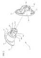
- FIG. 1is an exploded perspective view of the interspinous process device of this invention viewed from the distal end of the device;
- FIG. 2is a partially exploded perspective view of the interspinous process device of this invention viewed from the proximal end of the device;
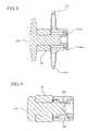
- FIG. 3is a proximal perspective view of the interspinous process device of this invention in the implantation configuration
- FIG. 4is a distal perspective view of the interspinous process device of this invention in the locked configuration
- FIG. 5is a proximal perspective view of the interspinous process device of this invention in the locked configuration
- FIG. 6is a cross-sectional view of the interspinous process device of this invention taken along lines 6 - 6 of FIG. 3 ;
- FIG. 7is a cross-sectional view of the interspinous process device of this invention taken along lines 7 - 7 of FIG. 3 ;
- FIG. 8is a cross-sectional view of the interspinous process device of this invention taken along lines 8 - 8 of FIG. 5 ;
- FIG. 9is a cross-sectional view of the interspinous process device of this invention taken along lines 9 - 9 of FIG. 5 ;
- FIG. 10is an end elevation view of the proximal retention member of the interspinous process device of this invention.
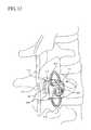
- FIG. 11is a schematic view of a portion of a human spine showing a dissected interspinous ligament in the space between adjacent spinous processes where the interspinous process device of this invention is to be implanted;
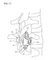
- FIGS. 12-15are schematic illustrations of the interspinous process device of this invention and a portion of a human spine that illustrate the method of implanting the interspinous process device of this invention.
- proximal and distalrefer to directions closer to and away from, respectively, an operator (e.g., surgeon, physician, nurse, technician, etc.) who would insert the medical device into the patient, with the tip-end (i.e., distal end) of the device inserted inside a patient's body first.
- an operatore.g., surgeon, physician, nurse, technician, etc.
- the tip-endi.e., distal end of the device inserted inside a patient's body first.
- the device end first inserted inside the patient's bodywould be the distal end of the device, while the device end last to enter the patient's body would be the proximal end of the device.
- the term “body” when used in connection with the location where the device of this invention is to be placed to treat lumbar spinal stenosis, or to teach or practice implantation methods for the devicemeans a mammalian body.
- a bodycan be a patient's body, or a cadaver, or a portion of a patient's body or a portion of a cadaver.
- paralleldescribes a relationship, given normal manufacturing or measurement or similar tolerances, between two geometric constructions (e.g., two lines, two planes, a line and a plane, two curved surfaces, a line and a curved surface or the like) in which the two geometric constructions are substantially non-intersecting as they extend substantially to infinity.
- two geometric constructionse.g., two lines, two planes, a line and a plane, two curved surfaces, a line and a curved surface or the like
- a lineis said to be parallel to a curved surface when the line and the curved surface do not intersect as they extend to infinity.
- planar surfacei.e., a two-dimensional surface
- every point along the lineis spaced apart from the nearest portion of the surface by a substantially equal distance.
- Two geometric constructionsare described herein as being “parallel” or “substantially parallel” to each other when they are nominally parallel to each other, such as for example, when they are parallel to each other within a tolerance.
- tolerancescan include, for example, manufacturing tolerances, measurement tolerances or the like.
- normalperpendicular
- orthoganaldescribe a relationship between two geometric constructions (e.g., two lines, two planes, a line and a plane, two curved surfaces, a line and a curved surface or the like) in which the two geometric constructions intersect at an angle of approximately 90 degrees within at least one plane.
- a lineis said to be normal, perpendicular or orthoganal to a curved surface when the line and the curved surface intersect at an angle of approximately 90 degrees within a plane.
- Two geometric constructionsare described herein as being “normal”, “perpendicular”, “orthogonal” or “substantially normal”, “substantially perpendicular”, “substantially orthogonal” to each other when they are nominally 90 degrees to each other, such as for example, when they are 90 degrees to each other within a tolerance.
- tolerancescan include, for example, manufacturing tolerances, measurement tolerances or the like.
- the interspinous process device 10 of this inventionincludes (i) a main body portion 100 having a shaft 120 that is adapted to be disposed between adjacent spinous processes and a distal retention member 110 adapted to be disposed along a lateral side of a superior spinous process and an inferior spinous process, and (ii) a proximal retention member 200 adapted to be disposed along an opposite lateral side of the superior spinous process and the inferior spinous process.
- a damper ring 20may also be located around shaft 120 of main body portion 100 between distal retention member 110 and proximal retention member 200 .
- proximal portion of shaft 120has a larger diameter than the remainder of shaft 120 to define a recessed area between distal retention member 110 and the proximal portion of shaft 120 into which damper ring 20 may fit. See e.g. FIG. 1 .
- Proximal retention member 200includes a central portion 220 which defines a central lumen 225 into which a proximal portion of shaft 120 of main body portion 100 may be located so that proximal retention member 200 is rotatable with respect to main body portion 100 .
- Distal retention member 110includes a distal upper wing 111 and a distal lower wing 112 .
- Distal upper wing 111is adapted to engage a distal side of a superior spinous process when device 10 is appropriately located in the space between adjacent spinous processes such that the longitudinal axis of damper ring 20 is generally perpendicular to the sagittal plane. See for example FIG. 15 .
- distal lower wing 112is adapted to engage a distal side of an inferior spinous process.
- distal retention member 110has a generally elliptical configuration with a major axis A 1 and a minor axis A 2 .
- distal retention member 110presents a smaller dimension in a first direction than in a direction normal to the first direction.
- the dimension of distal retention member 110 along the major axis A 1is greater than the distance between adjacent spinous processes when they are distracted to the desired spacing.
- the dimension of distal retention member 110 along the minor axis A 2is about equal to the distance between the adjacent spinous processes when they are distracted to the desired spacing.
- the proximal portion of shaft 120includes a slot 130 that cooperates with a complementary key 230 disposed within central lumen 225 of proximal retention member 200 .
- a complementary key 230disposed within central lumen 225 of proximal retention member 200 .
- two slots 130are located along the proximal portion of shaft 120 about 180 degrees apart. Even more preferably, slots 130 are aligned 180 degrees apart so that they are aligned along a line extending in a direction substantially parallel to the minor axis A 2 of distal retention member 110 .
- a plurality of lugsis also spaced around the periphery of shaft 120 adjacent to its proximal end. Preferably, these lugs are divided into two sets of lugs, which are spaced about 180 degrees apart such that each set is located between the pair of slots 130 .
- upper lugs 151 a and 151 bare generally aligned with distal upper wing 111
- lower lugs 152 a and 152 bare generally aligned with distal lower wing 112
- generally planar surfaces 135are located along the proximal portion of shaft 120 about 180 degrees apart, with each of planar surfaces 135 located adjacent to one set of lugs between each of slots 130 . Stated another way, planar surfaces 135 are substantially aligned along a line extending in a direction substantially parallel to major axis A 1 .
- Proximal retention member 200includes a proximal upper wing 210 and a proximal lower wing 215 , as well as a central portion 220 and central lumen 225 . As shown herein, proximal retention member 200 has a generally elliptical configuration with a major axis A 3 and a minor axis A 4 . Proximal retention member 200 is formed as a circumferential bar. However, proximal retention member 200 may have a solid configuration similar to distal retention member 110 . In addition, distal retention member 110 may be formed as a circumferential bar similar to proximal retention member 200 .
- proximal retention member 200Although an elliptical configuration is preferred for the configuration of proximal retention member 200 , any other geometrical shape may be used as long as proximal retention member 200 presents a smaller dimension in a first direction than in a direction normal to the first direction.
- the dimension of proximal retention member 200 along the major axis A 3is greater than the distance between adjacent spinous processes when they are distracted to the desired spacing.
- the length of proximal retention member 200 along major axis A 3is preferably greater than the length of distal retention member 110 along major axis A 1 . This greater dimension provides a visual cue for the surgeon so s/he can quickly determine which end is the proximal portion and which end is the distal portion.
- distal retention member 110be relatively small to facilitate implantation of the device. Typically, there is less room on the distal side of the spinous processes for the surgeon to manipulate the device.
- a key 230is formed in central lumen 225 in complementary receiving fashion with respect to slot 130 .
- Preferably two such keys 230are formed in central lumen 225 and are located about 180 degrees apart along the minor axis A 4 . This allows keys 230 to be aligned with planar surfaces 135 when the major axis A 1 of distal retention member 110 extends in a direction that is normal to the major axis A 3 of proximal retention member 200 .
- annular groove 250is formed along an internal surface of central lumen 225 along a proximal portion thereof.
- Annular groove 250is formed to act as a guide for lugs 151 a , 151 b , 152 a , and 152 b .
- lugs 151 a , 151 b , 152 a , and 152 bfit within annular groove 250 and can move along groove 250 as proximal retention member 200 rotates with respect to main body portion 100 about the longitudinal axis of main body portion 100 .
- lugs 151 a , 151 b , 152 a and 152 bhave tapered proximal ends to facilitate the movement of lugs 151 a , 151 b , 152 a and 152 b into annular groove 250 as main body portion 100 is moved in a direction along the longitudinal axis of shaft 120 into engagement with proximal retention member 200 during assembly of device 10 .
- lugs 151 a , 151 b , 152 a and 152 bhave a distal end that is substantially perpendicular to planar surface 135 .
- lugs 151 a , 151 b , 152 a and 152 bare difficult to remove from annular groove 250 and minimizes the possibility that main body portion 100 can be removed from proximal retention member 200 once device 10 is assembled.
- lugs 151 a and 151 bare separated a distance that is at least slightly greater than the width of key 230 .
- lugs 152 a and 152 bare separated a distance that is at least slightly greater than the width of key 230 .
- Planar surfaces 135provide sufficient space between the wall of central lumen 225 to allow keys 230 and the proximal portion of shaft 120 to fit within central lumen 225 .
- Key 230 and slot 130are configured such that key 230 fits snugly within slot 130 .
- key 230drops into slot 130 to lock proximal retention member 200 with respect to main body portion 100 .
- device 10can be located between adjacent spinous processes with shaft 120 and damper ring 20 located between adjacent spinous process such that they are substantially perpendicular to and cross the sagittal plane, distal upper wing 111 and distal lower wing 112 are located along the distal portion of the superior and inferior spinous processes respectively, and proximal upper retention member 210 and proximal lower retention member 215 are located along the proximal portion of the superior and inferior spinous processes respectively. This prevents device 10 from migrating from that location after implantation.
- locking mechanism(i) allows relative rotation between main body portion 100 and proximal retention member 200 , and (ii) locks main body portion 100 and proximal retention member 200 with respect to each other such that the major axis A 1 of distal retention member 110 extends in the same direction as the major axis A 3 of proximal retention member 200 .
- proximal retention member 200When device 10 is in the implantation configuration as shown for example in FIG. 3 , proximal retention member 200 is oriented such that major axis A 3 is substantially normal to the orientation of major axis A 1 of distal retention member 110 , i.e. major axis A 3 extends in a direction substantially normal to the direction of major axis A 1 .
- major axis A 3 of proximal retention member 200extends in a direction that is substantially aligned with major axis A 1 of distal retention member 110 , i.e. major axis A 3 extends in a direction substantially parallel to the direction of major axis A 1 .
- the arrangement of keys 230 and slots 130allows main body portion 100 to be rotated with respect to proximal retention member 200 about 90 degrees in either a clockwise or counterclockwise direction between the initial implantation position and the final locked position.
- the interspinous ligamentis typically dissected with a cutting instrument, such as a simple scalpel, an electrosurgical device or the like, not shown, to create an appropriately sized opening in the interspinous ligament to allow passage of a distal portion of device 10 therethrough. See FIG. 11 .
- a cutting instrumentsuch as a simple scalpel, an electrosurgical device or the like, not shown, to create an appropriately sized opening in the interspinous ligament to allow passage of a distal portion of device 10 therethrough. See FIG. 11 .
- a cutting instrumentsuch as a simple scalpel, an electrosurgical device or the like, not shown, to create an appropriately sized opening in the interspinous ligament to allow passage of a distal portion of device 10 therethrough. See FIG. 11 .
- Thisallows device 10 to be implanted in the space between adjacent spinous processes with a lateral approach. In most circumstances, the space between adjacent spinous processes may first need to be distracted with a distraction tool, not shown, to provide additional space and pain relief for the patient. After
- distal retention member 110is inserted through the opening formed in the interspinous ligament. See FIG. 12 .
- Distal retention member 110is oriented such that its major axis A 1 is generally parallel to the axial plane, with minor axis A 2 being generally parallel to the sagittal plane and the coronal plane. In this orientation, major axis A 1 would not be parallel to or normal to the sagittal and coronal planes. See FIG. 12 . In this orientation, the dimension of distal retention member 110 along minor axis A 2 does not hinder movement of device 10 through the space between adjacent spinous processes. Distal retention member 110 thus may be passed through the space between adjacent spinous processes with minimal disruption to the surrounding tissue.
- the supraspinous ligamentremains undisturbed during the procedure. It may be necessary for a leading edge of distal retention member 110 to be first passed through the space between the adjacent interspinous processes, with major axis A 1 not parallel to and not normal to the sagittal and coronal planes, in order to properly position device 10 . Once the leading edge of distal retention member 110 passes through the space formed in the interspinous ligament, device 10 may be rotated about an axis normal to the longitudinal axis of implant 10 so the longitudinal axis of implant 10 becomes parallel to the coronal and axial planes and normal to the sagittal plane. Compare FIG. 12 with FIG. 13 .
- distal retention member 110may have to be adjusted during the procedure in order to be properly placed in position.
- distal retention member 110may have to be rotated around the (i) longitudinal axis of device 10 , (ii) its major axis, and/or (iii) its minor axis during some portion or all of the implantation procedure. These manipulations may be necessary because of individual characteristics of the anatomy of the body into which device 10 is to be located.
- distal retention member 110may be rotated with respect to proximal retention member 200 about the longitudinal axis of main body portion 100 .
- Distal retention member 110may be rotated either clockwise or counterclockwise. This locks distal retention member 110 with respect to proximal retention member 200 such that major axis A 3 of proximal retention member 200 and major axis A 1 of distal retention member 110 are oriented such that they extend in the same direction and thus are generally parallel to each other and the sagittal and coronal planes and generally normal to the axial plane.
- major axes A 1 and A 3 of distal retention member 110 and proximal retention member 200respectively define a dimension that is greater than the distance between adjacent spinous processes, with the dimension for proximal retention member 200 preferably being greater.
- the distance between proximal retention member 200 and distal retention member 110should be slightly greater than the distance between the distal side of the adjacent spinous process and the proximal side of the adjacent spinous processes. In this manner, device 10 is held in place by proximal retention member 200 and distal retention member 110 .
- Device 10can be constructed with various biocompatible materials such as, for example, titanium, titanium alloy, surgical steel, biocompatible metal alloys, stainless steel, Nitinol, plastic, polyetheretherketone (PEEK), carbon fiber, ultra-high molecular weight (UHMW) polyethylene, and other biocompatible polymeric materials.
- the material of device 10can have, for example, a compressive strength similar to or higher than that of bone.
- damper ring 20which is placed between the two adjacent spinous processes, is formed from a material having an elastic modulus higher than the elastic modulus of the bone of the spinous processes.
- damper ring 20is formed from a material having a higher elastic modulus than the materials used to form main body portion 100 and proximal retention member 200 .
- damper ring 20may have an elastic modulus higher than bone, while main body portion 100 and proximal retention member 100 have a lower elastic modulus than bone.
- damper ring 20is formed of a compliant material, such as silicone, to dampen the shock when the spinal column is moved into extension.
Landscapes
- Health & Medical Sciences (AREA)
- Orthopedic Medicine & Surgery (AREA)
- Life Sciences & Earth Sciences (AREA)
- Neurology (AREA)
- Surgery (AREA)
- Heart & Thoracic Surgery (AREA)
- Engineering & Computer Science (AREA)
- Biomedical Technology (AREA)
- Nuclear Medicine, Radiotherapy & Molecular Imaging (AREA)
- Medical Informatics (AREA)
- Molecular Biology (AREA)
- Animal Behavior & Ethology (AREA)
- General Health & Medical Sciences (AREA)
- Public Health (AREA)
- Veterinary Medicine (AREA)
- Prostheses (AREA)
- Surgical Instruments (AREA)
Abstract
Description
This invention relates generally to the treatment of spinal conditions, and more particularly, to the treatment of spinal stenosis using devices for implantation between adjacent spinous processes.
The clinical syndrome of neurogenic intermittent claudication due to lumbar spinal stenosis is a frequent source of pain in the lower back and extremities, leading to impaired walking, and causing other forms of disability in the elderly. Although the incidence and prevalence of symptomatic lumbar spinal stenosis have not been established, this condition is the most frequent indication of spinal surgery in patients older than 65 years of age.
Lumbar spinal stenosis is a condition of the spine characterized by a narrowing of the lumbar spinal canal. With spinal stenosis, the spinal canal narrows and pinches the spinal cord and nerves, causing pain in the back and legs. It is estimated that approximately 5 in 10,000 people develop lumbar spinal stenosis each year. For patients who seek the aid of a physician for back pain, approximately 12%-15% are diagnosed as having lumbar spinal stenosis.
Common treatments for lumbar spinal stenosis include physical therapy (including changes in posture), medication, and occasionally surgery. Changes in posture and physical therapy may be effective in flexing the spine to decompress and enlarge the space available to the spinal cord and nerves—thus relieving pressure on pinched nerves. Medications such as NSAIDS and other anti-inflammatory medications are often used to alleviate pain, although they are not typically effective at addressing spinal compression, which is the cause of the pain.
Surgical treatments are more aggressive than medication or physical therapy, and in appropriate cases surgery may be the best way to achieve lessening of the symptoms of lumbar spinal stenosis. The principal goal of surgery is to decompress the central spinal canal and the neural foramina, creating more space and eliminating pressure on the spinal nerve roots. The most common surgery for treatment of lumbar spinal stenosis is direct decompression via a laminectomy and partial facetectomy. In this procedure, the patient is given a general anesthesia as an incision is made in the patient to access the spine. The lamina of one or more vertebrae is removed to create more space for the nerves. The intervertebral disc may also be removed, and the adjacent vertebrae may be fused to strengthen the unstable segments. The success rate of decompressive laminectomy has been reported to be in excess of 65%. A significant reduction of the symptoms of lumbar spinal stenosis is also achieved in many of these cases.
Alternatively, the vertebrae can be distracted and an interspinous process device implanted between adjacent spinous processes of the vertebrae to maintain the desired separation between the vertebral segments. Such interspinous process devices typically work for their intended purposes, but some could be improved. For example, many currently available interspinous process devices are challenging to properly place between adjacent spinous processes because of the space limitations in that area, which is filled with various muscles, ligaments, bone and other tissue. Some devices require a posterior to anterior approach. These types of devices are undesirable because they require that both the interspinous ligament and the supraspinous ligament be cut, or otherwise manipulated to allow the physician to gain access to the space between adjacent interspinous processes. In any surgical procedure, it is desirable to minimize trauma to surrounding tissue as much as possible in order to minimize recovery time for the patient and to provide the patient with the greatest chance for a successful outcome.
In view of the challenges with interspinous process devices that require a posterior to anterior approach, some devices have been designed that allow for a lateral approach. Some of these devices are significant improvements over those devices that require a direct posterior to anterior approach. However, even some devices that allow for a lateral approach to the space between adjacent spinous processes have challenges. As noted above, the space between adjacent spinous processes is confined. Thus it is difficult for the surgeon to manipulate the device to ensure that it is properly located in the space and to ensure that the device remains properly positioned therein. Where additional manipulation of the device is necessary to ensure that the device remains properly positioned in the desired space, the spatial limitations would be a factor militating against ease of insertion.
Thus, a need exists for improvements in interspinous process devices.
The interspinous process device of this invention includes (i) a main body portion having a shaft that is adapted to be disposed between adjacent spinous processes and a distal retention member adapted to be disposed along a lateral side of a superior spinous process, and an inferior spinous process, and (ii) a proximal retention member adapted to be disposed along an opposite lateral side of the superior spinous process and the inferior spinous process. A damper ring may also be located around the shaft of the main body portion between the proximal and distal retention members for engagement with the superior and inferior spinous processes. The proximal retention member has a central portion that defines a central lumen into which a proximal portion of the shaft of the main body portion may be located. The proximal portion of the shaft and the central lumen are configured so that the proximal retention member is rotatable with respect to the main body portion. Preferably, the length of the major axis of the distal retention member is greater than the distance between adjacent spinous processes when they are distracted to the desired spacing. Preferably, the length of the minor axis of the distal retention member is about equal to the distance between the adjacent spinous processes when they are distracted to the desired spacing.
When the interspinous process device of this invention is in an implantation configuration, the proximal retention member is oriented such that its major axis extends in a direction that is substantially normal to the orientation of the major axis of the distal retention member. When the interspinous process device is in its locked and final configuration, the major axis of the proximal retention member extends in a direction that is substantially aligned with and parallel to the major axis of the distal retention member. The proximal portion of the shaft includes a portion of a locking mechanism that cooperates with a complementary portion formed within the central lumen of the proximal retention member. This locking mechanism ensures that when the major axes of the proximal retention member and the distal retention member extend in a direction that is aligned and parallel to each other, the proximal retention member is locked with respect to the main body portion. Thus, the device can remain fixed in place between adjacent spinous processes such that the shaft and damper ring are disposed between the adjacent spinous processes and are substantially perpendicular to, and cross through, the sagittal plane. In this position, the distal retention member is located along the distal side of the superior and inferior spinous processes and the proximal retention member is located along the proximal side of the superior and inferior spinous processes such that the major axes of the distal and proximal retention members extend in a direction that is generally parallel to the sagittal and coronal planes and generally normal to the axial plane.
With the interspinous process device of this invention in the implantation configuration described above, the distal retention member is inserted through the interspinous ligament, which has been dissected to create an opening therethrough. This allows passage of the distal retention member therethrough, and through the space between adjacent spinous processes with a lateral approach. The distal retention member is oriented such that the major axis of the distal retention member is generally parallel to the axial plane but oriented at an angle to the sagittal and coronal planes. In this orientation, the minor axis is generally parallel to the sagittal plane and coronal plane and generally normal to the axial plane. This ensures that the dimension of the distal retention member along its minor axis does not hinder movement of the interspinous process device of this invention into the space between adjacent spinous processes. The distal retention member thus may be passed through the space between adjacent spinous processes with minimal disruption to the surrounding tissue. Importantly, the supraspinous ligament remains undisturbed during the procedure. It may be necessary for a leading edge of the distal retention member to be first passed through the space between the adjacent interspinous processes, in order to properly position the device. Of course, the orientation of the distal retention member may have to be adjusted in order to be properly placed in position. For example, the distal retention member may have to be rotated around the (i) longitudinal axis of the device, (ii) its major axis, and/or (iii) its minor axis during some part, or all, of the implantation procedure.
Once the distal retention member is adjacent to the distal side of the adjacent spinous processes, the distal retention member may be rotated with respect to the proximal retention member. This locks the distal retention member with respect to the proximal retention member such that the major axis of the proximal retention member and the major axis of the distal retention member extend in a direction that is generally parallel to each other and the sagittal and coronal planes and is generally normal to the axial plane. As noted above, the major axes of the distal retention member and the proximal retention member define a dimension that is greater than the distance between adjacent spinous processes. Preferably the dimension of the proximal retention member along its major axis is greater than the dimension of the distal retention member along its major axis. Of course, the distance between the proximal retention member and the distal retention member should be slightly greater than the distance between the distal side of the adjacent spinous process and the proximal side of the adjacent spinous processes. In this manner, the interspinous process device of this invention is held in place by the proximal and distal retention members and the shaft and/or the damper ring prevents the space between the adjacent spinous processes from collapsing during extension of the spine.
As used in this specification and the appended claims, the singular forms “a,” “an” and “the” include plural referents unless the context clearly dictates otherwise. Thus, for example, the term “a member” is intended to mean a single member or a combination of members, and “a material” is intended to mean one or more materials, or a combination thereof. Furthermore, the words “proximal” and “distal” refer to directions closer to and away from, respectively, an operator (e.g., surgeon, physician, nurse, technician, etc.) who would insert the medical device into the patient, with the tip-end (i.e., distal end) of the device inserted inside a patient's body first. Thus, for example, the device end first inserted inside the patient's body would be the distal end of the device, while the device end last to enter the patient's body would be the proximal end of the device.
As used in this specification and the appended claims, the term “body” when used in connection with the location where the device of this invention is to be placed to treat lumbar spinal stenosis, or to teach or practice implantation methods for the device, means a mammalian body. For example, a body can be a patient's body, or a cadaver, or a portion of a patient's body or a portion of a cadaver.
As used in this specification and the appended claims, the term “parallel” describes a relationship, given normal manufacturing or measurement or similar tolerances, between two geometric constructions (e.g., two lines, two planes, a line and a plane, two curved surfaces, a line and a curved surface or the like) in which the two geometric constructions are substantially non-intersecting as they extend substantially to infinity. For example, as used herein, a line is said to be parallel to a curved surface when the line and the curved surface do not intersect as they extend to infinity. Similarly, when a planar surface (i.e., a two-dimensional surface) is said to be parallel to a line, every point along the line is spaced apart from the nearest portion of the surface by a substantially equal distance. Two geometric constructions are described herein as being “parallel” or “substantially parallel” to each other when they are nominally parallel to each other, such as for example, when they are parallel to each other within a tolerance. Such tolerances can include, for example, manufacturing tolerances, measurement tolerances or the like.
As used in this specification and the appended claims, the terms “normal”, perpendicular” and “orthogonal” describe a relationship between two geometric constructions (e.g., two lines, two planes, a line and a plane, two curved surfaces, a line and a curved surface or the like) in which the two geometric constructions intersect at an angle of approximately 90 degrees within at least one plane. For example, as used herein, a line is said to be normal, perpendicular or orthoganal to a curved surface when the line and the curved surface intersect at an angle of approximately 90 degrees within a plane. Two geometric constructions are described herein as being “normal”, “perpendicular”, “orthogonal” or “substantially normal”, “substantially perpendicular”, “substantially orthogonal” to each other when they are nominally 90 degrees to each other, such as for example, when they are 90 degrees to each other within a tolerance. Such tolerances can include, for example, manufacturing tolerances, measurement tolerances or the like.
Theinterspinous process device 10 of this invention includes (i) amain body portion 100 having ashaft 120 that is adapted to be disposed between adjacent spinous processes and adistal retention member 110 adapted to be disposed along a lateral side of a superior spinous process and an inferior spinous process, and (ii) aproximal retention member 200 adapted to be disposed along an opposite lateral side of the superior spinous process and the inferior spinous process. Adamper ring 20 may also be located aroundshaft 120 ofmain body portion 100 betweendistal retention member 110 andproximal retention member 200. Preferably the proximal portion ofshaft 120 has a larger diameter than the remainder ofshaft 120 to define a recessed area betweendistal retention member 110 and the proximal portion ofshaft 120 into whichdamper ring 20 may fit. See e.g.FIG. 1 .Proximal retention member 200 includes acentral portion 220 which defines acentral lumen 225 into which a proximal portion ofshaft 120 ofmain body portion 100 may be located so thatproximal retention member 200 is rotatable with respect tomain body portion 100.
The proximal portion ofshaft 120 includes aslot 130 that cooperates with acomplementary key 230 disposed withincentral lumen 225 ofproximal retention member 200. Preferably twoslots 130 are located along the proximal portion ofshaft 120 about 180 degrees apart. Even more preferably,slots 130 are aligned 180 degrees apart so that they are aligned along a line extending in a direction substantially parallel to the minor axis A2 ofdistal retention member 110. A plurality of lugs is also spaced around the periphery ofshaft 120 adjacent to its proximal end. Preferably, these lugs are divided into two sets of lugs, which are spaced about 180 degrees apart such that each set is located between the pair ofslots 130. As shown,upper lugs upper wing 111, whilelower lugs lower wing 112. In addition, generallyplanar surfaces 135 are located along the proximal portion ofshaft 120 about 180 degrees apart, with each ofplanar surfaces 135 located adjacent to one set of lugs between each ofslots 130. Stated another way,planar surfaces 135 are substantially aligned along a line extending in a direction substantially parallel to major axis A1.
A key230 is formed incentral lumen 225 in complementary receiving fashion with respect to slot130. Preferably twosuch keys 230 are formed incentral lumen 225 and are located about 180 degrees apart along the minor axis A4. This allowskeys 230 to be aligned withplanar surfaces 135 when the major axis A1 ofdistal retention member 110 extends in a direction that is normal to the major axis A3 ofproximal retention member 200.
Anannular groove 250 is formed along an internal surface ofcentral lumen 225 along a proximal portion thereof.Annular groove 250 is formed to act as a guide forlugs annular groove 250 and can move alonggroove 250 asproximal retention member 200 rotates with respect tomain body portion 100 about the longitudinal axis ofmain body portion 100. Preferably, lugs151a,151b,152aand152bhave tapered proximal ends to facilitate the movement oflugs annular groove 250 asmain body portion 100 is moved in a direction along the longitudinal axis ofshaft 120 into engagement withproximal retention member 200 during assembly ofdevice 10. Preferably lugs151a,151b,152aand152bhave a distal end that is substantially perpendicular toplanar surface 135. This ensures that lugs151a,151b,152aand152bare difficult to remove fromannular groove 250 and minimizes the possibility thatmain body portion 100 can be removed fromproximal retention member 200 oncedevice 10 is assembled. In addition, lugs151aand151bare separated a distance that is at least slightly greater than the width ofkey 230. Similarly, lugs152aand152bare separated a distance that is at least slightly greater than the width ofkey 230. This allowskeys 230 to movepast lugs keys 230 are adjacentplanar surfaces 135. Planar surfaces135 provide sufficient space between the wall ofcentral lumen 225 to allowkeys 230 and the proximal portion ofshaft 120 to fit withincentral lumen 225.
Whendevice 10 is in the implantation configuration as shown for example inFIG. 3 ,proximal retention member 200 is oriented such that major axis A3 is substantially normal to the orientation of major axis A1 ofdistal retention member 110, i.e. major axis A3 extends in a direction substantially normal to the direction of major axis A1. Whendevice 10 is in its locked and final configuration as shown for example inFIG. 5 , major axis A3 ofproximal retention member 200 extends in a direction that is substantially aligned with major axis A1 ofdistal retention member 110, i.e. major axis A3 extends in a direction substantially parallel to the direction of major axis A1. The arrangement ofkeys 230 andslots 130 allowsmain body portion 100 to be rotated with respect toproximal retention member 200 about 90 degrees in either a clockwise or counterclockwise direction between the initial implantation position and the final locked position.
The interspinous ligament is typically dissected with a cutting instrument, such as a simple scalpel, an electrosurgical device or the like, not shown, to create an appropriately sized opening in the interspinous ligament to allow passage of a distal portion ofdevice 10 therethrough. SeeFIG. 11 . This allowsdevice 10 to be implanted in the space between adjacent spinous processes with a lateral approach. In most circumstances, the space between adjacent spinous processes may first need to be distracted with a distraction tool, not shown, to provide additional space and pain relief for the patient. After the physician confirms sufficient distraction,device 10 can then be placed in the space between the adjacent spinous processes.Device 10 can come in different sizes to accommodate different amounts of distraction/space needed between adjacent spinous processes.
Withdevice 10 in the implantation configuration described above,distal retention member 110 is inserted through the opening formed in the interspinous ligament. SeeFIG. 12 .Distal retention member 110 is oriented such that its major axis A1 is generally parallel to the axial plane, with minor axis A2 being generally parallel to the sagittal plane and the coronal plane. In this orientation, major axis A1 would not be parallel to or normal to the sagittal and coronal planes. SeeFIG. 12 . In this orientation, the dimension ofdistal retention member 110 along minor axis A2 does not hinder movement ofdevice 10 through the space between adjacent spinous processes.Distal retention member 110 thus may be passed through the space between adjacent spinous processes with minimal disruption to the surrounding tissue. Importantly, the supraspinous ligament remains undisturbed during the procedure. It may be necessary for a leading edge ofdistal retention member 110 to be first passed through the space between the adjacent interspinous processes, with major axis A1 not parallel to and not normal to the sagittal and coronal planes, in order to properly positiondevice 10. Once the leading edge ofdistal retention member 110 passes through the space formed in the interspinous ligament,device 10 may be rotated about an axis normal to the longitudinal axis ofimplant 10 so the longitudinal axis ofimplant 10 becomes parallel to the coronal and axial planes and normal to the sagittal plane. CompareFIG. 12 withFIG. 13 . This also placesproximal retention member 200 along the proximal side of adjacent superior and inferior spinous processes with major axis A3 generally parallel to the sagittal and coronal planes and generally normal to the axial plane. Of course, the orientation ofdistal retention member 110 may have to be adjusted during the procedure in order to be properly placed in position. For example,distal retention member 110 may have to be rotated around the (i) longitudinal axis ofdevice 10, (ii) its major axis, and/or (iii) its minor axis during some portion or all of the implantation procedure. These manipulations may be necessary because of individual characteristics of the anatomy of the body into whichdevice 10 is to be located.
Oncedistal retention member 110 is adjacent to the distal side of the adjacent spinous processes, seeFIGS. 13 and 14 ,distal retention member 110 may be rotated with respect toproximal retention member 200 about the longitudinal axis ofmain body portion 100.Distal retention member 110 may be rotated either clockwise or counterclockwise. This locksdistal retention member 110 with respect toproximal retention member 200 such that major axis A3 ofproximal retention member 200 and major axis A1 ofdistal retention member 110 are oriented such that they extend in the same direction and thus are generally parallel to each other and the sagittal and coronal planes and generally normal to the axial plane. As noted above, major axes A1 and A3 ofdistal retention member 110 andproximal retention member 200 respectively define a dimension that is greater than the distance between adjacent spinous processes, with the dimension forproximal retention member 200 preferably being greater. Of course, the distance betweenproximal retention member 200 anddistal retention member 110 should be slightly greater than the distance between the distal side of the adjacent spinous process and the proximal side of the adjacent spinous processes. In this manner,device 10 is held in place byproximal retention member 200 anddistal retention member 110.
While various embodiments of the invention have been described above, it should be understood that they have been presented by way of example only, and not limitation. The foregoing description of the interspinous process device is not intended to be exhaustive or to limit the invention of the device. Many modifications and variations will be apparent to the practitioner skilled in the art. It is intended that the scope of the invention be defined by the following claims and their equivalents.
Claims (16)
1. A device, comprising:
a first retention member having a central portion defining a longitudinal axis and an upper wing extending outward from the central portion transverse to the longitudinal axis, a lower wing extending outward from the central portion in a direction opposite to the upper wing and transverse to the longitudinal axis wherein the upper wing of the first retention member and the lower wing of the first retention member are configured to be disposed along a first side of a superior spinous process and an inferior spinous process; and
a main body portion extending along the longitudinal axis and having a second retention member including an upper wing extending outward from the main body portion transverse to the longitudinal axis a lower wing extending outward from the main body portion in a direction opposite to the upper wing and transverse to the longitudinal axis wherein the upper wing of the second retention member and the lower wing of the second retention member are configured to be disposed along a second side of a superior spinous process and an inferior spinous process opposite the first side and being rotatable with respect to the first retention member between a first position such that upper and lower wings of the main body are disposed perpendicular to the upper and lower wings of the first retention member and a second position such that upper and lower wings of the main body are disposed parallel to the upper and lower wings of the first retention member,
wherein the main body portion is rotatable between the first position and the second position.
2. The device ofclaim 1 wherein the longitudinal axis of the main body portion extends from a proximal portion to a distal portion of the main body portion and wherein the second retention member is adjacent to the distal portion.
3. The device ofclaim 2 wherein in the second position the main body portion is not rotatable with respect to the first retention member.
4. The device ofclaim 1 wherein the second retention member has a surface area that is smaller than the surface area of the first retention member.
5. The device ofclaim 1 further comprising a damper ring disposed about the main body portion between the first retention member and the second retention member.
6. The device ofclaim 1 wherein the first retention member defines a first major axis and a first minor axis and the second retention member defines a second major axis and a second minor axis such that in the first position the first major axis and the first minor axis extend in directions that are generally perpendicular to the directions in which the second major axis and the second minor axis respectively extend.
7. The device ofclaim 1 wherein the first retention member defines a first major axis and a first minor axis and the second retention member defines a second major axis and a second minor axis such that in the second position the first major axis and the first minor axis extend in directions that are generally parallel to the directions in which the second major axis and the second minor axis respectively extend.
8. The device ofclaim 7 further comprising a lock adapted to lock the first retention member and the main body portion in the second position.
9. A device, comprising:
a proximal retention member defining a central lumen therein, the proximal retention member includes a central portion defining a longitudinal axis and an upper wing extending outward from the central portion transverse to the longitudinal axis a lower wing extending outward from the central portion in a direction opposite to the upper wing and transverse to the longitudinal axis wherein the upper wing of the proximal retention member and the lower wing of the proximal retention member are configured to be disposed along a first side of a superior spinous process and an inferior spinous process;
a main body portion extending along the longitudinal axis and having a distal retention member and a shaft having a proximal portion and a distal portion extending proximally from the distal retention member wherein the proximal portion is disposed in the central lumen, the distal retention member including an upper wing extending outward from the main body portion transverse to the longitudinal axis a lower wing extending outward from the main body portion in a direction opposite to the upper wing and transverse to the longitudinal axis wherein the upper wing of the distal retention member and the lower wing of the distal retention member are configured to be disposed along a second side of a superior spinous process and an inferior spinous process opposite the first side;
at least one key disposed in the central lumen; and
the proximal portion of the shaft defining at least one slot adapted to engage the at least one key,
wherein the main body portion is rotatable between a first position such that upper and lower wings of the main body are disposed perpendicular to the upper and lower wings of the first retention member and a second position such that upper and lower wings of the main body are disposed parallel to the upper and lower wings of the first retention member.
10. The device ofclaim 9 wherein the proximal retention member includes a major axis and a minor axis and further comprising two keys located about 180 degrees apart along the minor axis.
11. The device ofclaim 10 wherein the distal retention member includes a major axis and a minor axis and the proximal portion of the shaft defines two slots therein about 180 degrees apart generally aligned along a line substantially parallel to the minor axis of the distal retention member.
12. The device ofclaim 10 wherein the proximal portion of the shaft defines two generally planar surfaces each disposed between the two slots.
13. The device ofclaim 12 further comprising a plurality of lugs disposed adjacent to the proximal portion of the shaft wherein the lugs are adjacent to the generally planar surfaces.
14. The device ofclaim 9 further comprising a plurality of lugs disposed adjacent to the proximal portion of the shaft.
15. The device ofclaim 14 further comprising an annular groove disposed about the central lumen adjacent to a proximal portion thereof with the plurality of lugs adapted to be disposed in and movable with respect to the annular groove.
16. The device ofclaim 9 further comprising a damper ring disposed about the shaft.
Priority Applications (3)
| Application Number | Priority Date | Filing Date | Title |
|---|---|---|---|
| US12/607,917US8771317B2 (en) | 2009-10-28 | 2009-10-28 | Interspinous process implant and method of implantation |
| JP2010239486AJP2011092712A (en) | 2009-10-28 | 2010-10-26 | Interspinous process implant and method of implantation |
| EP10189284AEP2316362A1 (en) | 2009-10-28 | 2010-10-28 | Interspinous process implant |
Applications Claiming Priority (1)
| Application Number | Priority Date | Filing Date | Title |
|---|---|---|---|
| US12/607,917US8771317B2 (en) | 2009-10-28 | 2009-10-28 | Interspinous process implant and method of implantation |
Publications (2)
| Publication Number | Publication Date |
|---|---|
| US20110098745A1 US20110098745A1 (en) | 2011-04-28 |
| US8771317B2true US8771317B2 (en) | 2014-07-08 |
Family
ID=43245001
Family Applications (1)
| Application Number | Title | Priority Date | Filing Date |
|---|---|---|---|
| US12/607,917Active2031-11-11US8771317B2 (en) | 2009-10-28 | 2009-10-28 | Interspinous process implant and method of implantation |
Country Status (3)
| Country | Link |
|---|---|
| US (1) | US8771317B2 (en) |
| EP (1) | EP2316362A1 (en) |
| JP (1) | JP2011092712A (en) |
Cited By (1)
| Publication number | Priority date | Publication date | Assignee | Title |
|---|---|---|---|---|
| US9662150B1 (en) | 2007-02-26 | 2017-05-30 | Nuvasive, Inc. | Spinal stabilization system and methods of use |
Families Citing this family (11)
| Publication number | Priority date | Publication date | Assignee | Title |
|---|---|---|---|---|
| US8945184B2 (en)* | 2009-03-13 | 2015-02-03 | Spinal Simplicity Llc. | Interspinous process implant and fusion cage spacer |
| US8262697B2 (en)* | 2010-01-14 | 2012-09-11 | X-Spine Systems, Inc. | Modular interspinous fixation system and method |
| US20120215262A1 (en)* | 2011-02-16 | 2012-08-23 | Interventional Spine, Inc. | Spinous process spacer and implantation procedure |
| KR101066324B1 (en)* | 2011-04-06 | 2011-09-20 | 유창화 | Spinal process spacer |
| US20120323276A1 (en)* | 2011-06-17 | 2012-12-20 | Bryan Okamoto | Expandable interspinous device |
| US9149306B2 (en) | 2011-06-21 | 2015-10-06 | Seaspine, Inc. | Spinous process device |
| AU2013249305B2 (en) | 2012-04-17 | 2017-05-11 | Aurora Spine, Llc | A dynamic and non-dynamic interspinous fusion implant and bone growth stimulation system |
| WO2016137983A1 (en) | 2015-02-24 | 2016-09-01 | X-Spine Systems, Inc. | Modular interspinous fixation system with threaded component |
| KR101952597B1 (en) | 2017-02-13 | 2019-02-27 | (주)시지바이오 | Implant for bone substitute |
| KR102446311B1 (en) | 2017-05-02 | 2022-09-23 | 가톨릭대학교 산학협력단 | Bone union member and spinous process implant having same |
| US12133664B2 (en) | 2022-12-13 | 2024-11-05 | Spinal Simplicity, Llc | Medical implant |
Citations (284)
| Publication number | Priority date | Publication date | Assignee | Title |
|---|---|---|---|---|
| US624969A (en) | 1899-05-16 | Peter peterson | ||
| US1153797A (en) | 1915-04-29 | 1915-09-14 | Jules Emile Kegreisz | Expansion-anchor. |
| US1516347A (en) | 1923-08-30 | 1924-11-18 | Pataky Anton | Coupling pin |
| US2077804A (en) | 1936-05-19 | 1937-04-20 | Morrison Gordon Monroe | Device for treating fractures of the neck of the femur |
| US2299308A (en) | 1941-08-15 | 1942-10-20 | Russell A Creighton | Self-locking spike |
| US2485531A (en) | 1948-01-13 | 1949-10-18 | Dzus William | Surgical toggle bolt |
| US2607370A (en) | 1948-07-13 | 1952-08-19 | Oscar F Anderson | Pipe plug |
| US2677369A (en) | 1952-03-26 | 1954-05-04 | Fred L Knowles | Apparatus for treatment of the spinal column |
| US2685877A (en) | 1952-03-20 | 1954-08-10 | Dobelle Martin | Femoral head prosthesis |
| US3065659A (en) | 1959-09-28 | 1962-11-27 | Superior Concrete Accessories | Expansion bolt |
| US3426364A (en) | 1966-08-25 | 1969-02-11 | Colorado State Univ Research F | Prosthetic appliance for replacing one or more natural vertebrae |
| US3648691A (en) | 1970-02-24 | 1972-03-14 | Univ Colorado State Res Found | Method of applying vertebral appliance |
| US3779239A (en) | 1971-03-13 | 1973-12-18 | Fischer Artur | Connector for fractured bones |
| US4011602A (en) | 1975-10-06 | 1977-03-15 | Battelle Memorial Institute | Porous expandable device for attachment to bone tissue |
| DE2821678A1 (en) | 1978-05-12 | 1979-11-22 | Sulzer Ag | IMPLANT THAT CAN BE INSERTED BETWEEN NEIGHBORING Vertebrae |
| US4237875A (en) | 1979-02-23 | 1980-12-09 | Towmotor Corporation | Dynamic intramedullary compression nailing |
| US4257409A (en) | 1978-04-14 | 1981-03-24 | Kazimierz Bacal | Device for treatment of spinal curvature |
| US4274324A (en) | 1978-04-18 | 1981-06-23 | Giannuzzi Louis | Hollow wall screw anchor |
| US4289123A (en) | 1980-03-31 | 1981-09-15 | Dunn Harold K | Orthopedic appliance |
| SU988281A1 (en) | 1981-06-26 | 1983-01-15 | За витель | Vertical column fixing device |
| US4401112A (en) | 1980-09-15 | 1983-08-30 | Rezaian Seyed M | Spinal fixator |
| US4519100A (en) | 1982-09-30 | 1985-05-28 | Orthopedic Equipment Co. Inc. | Distal locking intramedullary nail |
| US4553273A (en) | 1983-11-23 | 1985-11-19 | Henry Ford Hospital | Vertebral body prosthesis and spine stabilizing method |
| US4554914A (en) | 1983-10-04 | 1985-11-26 | Kapp John P | Prosthetic vertebral body |
| US4573454A (en) | 1984-05-17 | 1986-03-04 | Hoffman Gregory A | Spinal fixation apparatus |
| US4599086A (en) | 1985-06-07 | 1986-07-08 | Doty James R | Spine stabilization device and method |
| US4604995A (en) | 1984-03-30 | 1986-08-12 | Stephens David C | Spinal stabilizer |
| US4611582A (en) | 1983-12-27 | 1986-09-16 | Wisconsin Alumni Research Foundation | Vertebral clamp |
| US4632101A (en) | 1985-01-31 | 1986-12-30 | Yosef Freedland | Orthopedic fastener |
| US4636217A (en) | 1985-04-23 | 1987-01-13 | Regents Of The University Of Minnesota | Anterior spinal implant |
| US4646998A (en) | 1981-11-20 | 1987-03-03 | Clairson International Corporation | Wall-mounted shelf support clip |
| US4657550A (en) | 1984-12-21 | 1987-04-14 | Daher Youssef H | Buttressing device usable in a vertebral prosthesis |
| US4662808A (en) | 1985-10-02 | 1987-05-05 | Lee-Rowan Company | Wall anchor |
| US4686970A (en) | 1983-12-15 | 1987-08-18 | A. W. Showell (Surgicraft) Limited | Devices for spinal fixation |
| US4704057A (en) | 1976-09-15 | 1987-11-03 | Mechanical Plastics Corp. | Fastening element |
| US4759769A (en) | 1987-02-12 | 1988-07-26 | Health & Research Services Inc. | Artificial spinal disc |
| US4787378A (en) | 1986-09-08 | 1988-11-29 | Sodhi Jitendra S | Self-retaining nail for fracture of neck of femur |
| US4822226A (en) | 1983-08-08 | 1989-04-18 | Kennedy Arvest G | Wing nut retainer and extractor |
| US4827918A (en) | 1985-08-15 | 1989-05-09 | Sven Olerud | Fixing instrument for use in spinal surgery |
| FR2623085A1 (en) | 1987-11-16 | 1989-05-19 | Breard Francis | SURGICAL IMPLANT FOR LIMITING THE RELATIVE MOVEMENT OF VERTEBRATES |
| US4834600A (en) | 1988-08-25 | 1989-05-30 | Lemke Stuart H | Fastener assembly |
| SU1484348A1 (en) | 1987-03-04 | 1989-06-07 | Белорусский научно-исследовательский институт травматологии и ортопедии | Spinal column fixing device |
| FR2625097A1 (en) | 1987-12-23 | 1989-06-30 | Cote Sarl | INTER-EPINEUS PROSTHESIS COMPOSED IN A SEMI-ELASTIC MATERIAL AND COMPRISING A TRANSFILING EYE AT ITS END AND INTER-SPINOUS CUSHIONETS |
| US4863476A (en) | 1986-08-29 | 1989-09-05 | Shepperd John A N | Spinal implant |
| US4886405A (en) | 1989-01-27 | 1989-12-12 | Blomberg Ingvar M | Wall mounting device |
| US4892545A (en) | 1988-07-14 | 1990-01-09 | Ohio Medical Instrument Company, Inc. | Vertebral lock |
| US4913144A (en) | 1988-08-03 | 1990-04-03 | D.A.O. S.R.L. | Adjustable staple |
| US4931055A (en) | 1986-05-30 | 1990-06-05 | John Bumpus | Distraction rods |
| US4932975A (en) | 1989-10-16 | 1990-06-12 | Vanderbilt University | Vertebral prosthesis |
| US4969887A (en) | 1986-09-08 | 1990-11-13 | Sodhi Jitendra S | Self-retaining nail kit for repairing a fractured neck of femur |
| DE3922044A1 (en) | 1989-07-05 | 1991-02-07 | Richter Turtur Matthias Dr | Treatment of fractured vertebra - by instrument which avoids any force on intact adjacent to vertebrae |
| DE4012622C1 (en) | 1990-04-20 | 1991-07-18 | Eska Medical Luebeck Medizintechnik Gmbh & Co, 2400 Luebeck, De | Two-part metal vertebra implant - has parts locked by two toothed racks, pre-stressed by elastic cushion between both implant parts |
| US5047055A (en) | 1990-12-21 | 1991-09-10 | Pfizer Hospital Products Group, Inc. | Hydrogel intervertebral disc nucleus |
| US5059193A (en) | 1989-11-20 | 1991-10-22 | Spine-Tech, Inc. | Expandable spinal implant and surgical method |
| US5092866A (en) | 1989-02-03 | 1992-03-03 | Breard Francis H | Flexible inter-vertebral stabilizer as well as process and apparatus for determining or verifying its tension before installation on the spinal column |
| US5098433A (en) | 1989-04-12 | 1992-03-24 | Yosef Freedland | Winged compression bolt orthopedic fastener |
| US5171278A (en) | 1991-02-22 | 1992-12-15 | Madhavan Pisharodi | Middle expandable intervertebral disk implants |
| FR2681525A1 (en) | 1991-09-19 | 1993-03-26 | Medical Op | Device for flexible or semi-rigid stabilisation of the spine, in particular of the human spine, by a posterior route |
| US5201734A (en) | 1988-12-21 | 1993-04-13 | Zimmer, Inc. | Spinal locking sleeve assembly |
| US5290312A (en) | 1991-09-03 | 1994-03-01 | Alphatec | Artificial vertebral body |
| US5306310A (en) | 1991-08-27 | 1994-04-26 | Man Ceramics Gmbh | Vertebral prosthesis |
| US5306275A (en) | 1992-12-31 | 1994-04-26 | Bryan Donald W | Lumbar spine fixation apparatus and method |
| US5312405A (en) | 1992-07-06 | 1994-05-17 | Zimmer, Inc. | Spinal rod coupler |
| FR2700941A1 (en) | 1993-02-03 | 1994-08-05 | Felman Daniel | Monobloc interspinal intervertebral fixation implant |
| FR2703239A1 (en) | 1993-03-30 | 1994-10-07 | Brio Bio Rhone Implant Medical | Pin for interspinal prosthesis |
| US5360430A (en) | 1993-07-29 | 1994-11-01 | Lin Chih I | Intervertebral locking device |
| US5366455A (en) | 1988-11-04 | 1994-11-22 | Surgicraft Limited | Pedicle engaging means |
| FR2707864A1 (en) | 1993-07-23 | 1995-01-27 | Taylor Jean | Surgical clamp for tensioning an osteosynthesis ligament |
| US5390683A (en) | 1991-02-22 | 1995-02-21 | Pisharodi; Madhavan | Spinal implantation methods utilizing a middle expandable implant |
| US5395370A (en) | 1991-10-18 | 1995-03-07 | Pina Vertriebs Ag | Vertebral compression clamp for surgical repair to damage to the spine |
| US5401269A (en) | 1992-03-13 | 1995-03-28 | Waldemar Link Gmbh & Co. | Intervertebral disc endoprosthesis |
| US5403316A (en) | 1993-12-02 | 1995-04-04 | Danek Medical, Inc. | Triangular construct for spinal fixation |
| US5415661A (en) | 1993-03-24 | 1995-05-16 | University Of Miami | Implantable spinal assist device |
| US5437674A (en) | 1992-08-25 | 1995-08-01 | Alexandre Worcel | Osteosynthesis device |
| US5437672A (en) | 1992-11-12 | 1995-08-01 | Alleyne; Neville | Spinal cord protection device |
| US5439463A (en) | 1993-11-12 | 1995-08-08 | Lin; Chih-I | Spinal clamping device |
| FR2717675A1 (en) | 1994-03-24 | 1995-09-29 | Taylor Jean | Shock-absorbing spacer block for location between adjacent vertebrae implanted during spinal surgery |
| US5454812A (en) | 1993-11-12 | 1995-10-03 | Lin; Chih-I | Spinal clamping device having multiple distance adjusting strands |
| US5458641A (en) | 1993-09-08 | 1995-10-17 | Ramirez Jimenez; Juan J. | Vertebral body prosthesis |
| US5474561A (en)* | 1994-02-01 | 1995-12-12 | Yao; Meei-Huei | All positional and universal guiding device for interlocking intramedullary nail |
| FR2722088A1 (en) | 1994-07-08 | 1996-01-12 | Cahlik Marc Andre | Surgical implant for stabilising intervertebral spaces |
| FR2722087A1 (en) | 1994-07-08 | 1996-01-12 | Cahlik Marc Andre | Surgical implant for limiting relative movement of vertebrae |
| US5496318A (en) | 1993-01-08 | 1996-03-05 | Advanced Spine Fixation Systems, Inc. | Interspinous segmental spine fixation device |
| FR2724554A1 (en) | 1994-09-16 | 1996-03-22 | Voydeville Gilles | Fastening for artificial ligaments of inter-vertebral prosthesis |
| FR2725892A1 (en) | 1994-10-21 | 1996-04-26 | Felman Daniel | Vertebral implant insertion process using shape memory material |
| US5518498A (en) | 1992-10-09 | 1996-05-21 | Angiomed Ag | Stent set |
| FR2730156A1 (en) | 1995-02-03 | 1996-08-09 | Textile Hi Tec | Inter-spinal wedge implant useful esp. for vertebral prosthesis |
| US5554191A (en) | 1994-01-26 | 1996-09-10 | Biomat | Intersomatic vertebral cage |
| FR2731643A1 (en) | 1995-03-16 | 1996-09-20 | Jbs Sa | ANGULAR SCREWDRIVER DEVICE FOR SCREWING IN AND SCREWING DIFFICULT ACCESSIBLE SCREWS, PARTICULARLY IN THE SURGICAL FIELD |
| US5562735A (en) | 1992-11-09 | 1996-10-08 | Hospital For Joint Diseases | Spinal stabilization system and improved method |
| US5562662A (en) | 1993-01-04 | 1996-10-08 | Danek Medical Inc. | Spinal fixation system and method |
| US5571192A (en) | 1994-07-02 | 1996-11-05 | Heinrich Ulrich | Prosthetic vertebral implant |
| US5609635A (en) | 1988-06-28 | 1997-03-11 | Michelson; Gary K. | Lordotic interbody spinal fusion implants |
| US5609634A (en) | 1992-07-07 | 1997-03-11 | Voydeville; Gilles | Intervertebral prosthesis making possible rotatory stabilization and flexion/extension stabilization |
| US5628756A (en) | 1993-01-06 | 1997-05-13 | Smith & Nephew Richards Inc. | Knotted cable attachment apparatus formed of braided polymeric fibers |
| US5630816A (en) | 1995-05-01 | 1997-05-20 | Kambin; Parviz | Double barrel spinal fixation system and method |
| US5645599A (en) | 1994-07-26 | 1997-07-08 | Fixano | Interspinal vertebral implant |
| US5653763A (en) | 1996-03-29 | 1997-08-05 | Fastenetix, L.L.C. | Intervertebral space shape conforming cage device |
| US5653762A (en) | 1994-03-18 | 1997-08-05 | Pisharodi; Madhavan | Method of stabilizing adjacent vertebrae with rotating, lockable, middle-expanded intervertebral disk stabilizer |
| US5658335A (en) | 1995-03-09 | 1997-08-19 | Cohort Medical Products Group, Inc. | Spinal fixator |
| US5665122A (en) | 1995-01-31 | 1997-09-09 | Kambin; Parviz | Expandable intervertebral cage and surgical method |
| US5674295A (en) | 1994-10-17 | 1997-10-07 | Raymedica, Inc. | Prosthetic spinal disc nucleus |
| US5676702A (en) | 1994-12-16 | 1997-10-14 | Tornier S.A. | Elastic disc prosthesis |
| US5685826A (en) | 1990-11-05 | 1997-11-11 | General Surgical Innovations, Inc. | Mechanically expandable arthroscopic retractors and method of using the same |
| US5690649A (en) | 1995-12-05 | 1997-11-25 | Li Medical Technologies, Inc. | Anchor and anchor installation tool and method |
| US5693100A (en) | 1991-02-22 | 1997-12-02 | Pisharodi; Madhavan | Middle expandable intervertebral disk implant |
| US5702395A (en) | 1992-11-10 | 1997-12-30 | Sofamor S.N.C. | Spine osteosynthesis instrumentation for an anterior approach |
| US5702452A (en) | 1995-01-23 | 1997-12-30 | Sofamor S.N.C. | Spinal osteosynthesis device with median hook and vertebral anchoring support |
| US5702455A (en) | 1996-07-03 | 1997-12-30 | Saggar; Rahul | Expandable prosthesis for spinal fusion |
| US5707390A (en) | 1990-03-02 | 1998-01-13 | General Surgical Innovations, Inc. | Arthroscopic retractors |
| US5716416A (en) | 1996-09-10 | 1998-02-10 | Lin; Chih-I | Artificial intervertebral disk and method for implanting the same |
| US5723013A (en) | 1995-02-06 | 1998-03-03 | Jbs S.A. | Spacer implant for substituting missing vertebrae |
| US5725341A (en) | 1997-01-08 | 1998-03-10 | Hofmeister; Oskar | Self fusing fastener |
| US5746762A (en) | 1996-06-24 | 1998-05-05 | Bass; Lawrence S. | Device and method for surgical flap dissection |
| US5755797A (en) | 1993-04-21 | 1998-05-26 | Sulzer Medizinaltechnik Ag | Intervertebral prosthesis and a process for implanting such a prosthesis |
| US5800547A (en) | 1994-08-20 | 1998-09-01 | Schafer Micomed Gmbh | Ventral intervertebral implant |
| US5810815A (en) | 1996-09-20 | 1998-09-22 | Morales; Jose A. | Surgical apparatus for use in the treatment of spinal deformities |
| US5836948A (en) | 1997-01-02 | 1998-11-17 | Saint Francis Medical Technologies, Llc | Spine distraction implant and method |
| US5849004A (en) | 1996-07-17 | 1998-12-15 | Bramlet; Dale G. | Surgical anchor |
| US5860977A (en) | 1997-01-02 | 1999-01-19 | Saint Francis Medical Technologies, Llc | Spine distraction implant and method |
| EP0767636B1 (en) | 1994-05-11 | 1999-01-20 | Jean Taylor | Vertebral implant |
| FR2775183A1 (en) | 1998-02-20 | 1999-08-27 | Jean Taylor | INTER-SPINOUS PROSTHESIS |
| US5976186A (en) | 1994-09-08 | 1999-11-02 | Stryker Technologies Corporation | Hydrogel intervertebral disc nucleus |
| US5980523A (en) | 1998-01-08 | 1999-11-09 | Jackson; Roger | Transverse connectors for spinal rods |
| US6022376A (en) | 1997-06-06 | 2000-02-08 | Raymedica, Inc. | Percutaneous prosthetic spinal disc nucleus and method of manufacture |
| US6048342A (en) | 1997-01-02 | 2000-04-11 | St. Francis Medical Technologies, Inc. | Spine distraction implant |
| US6068630A (en) | 1997-01-02 | 2000-05-30 | St. Francis Medical Technologies, Inc. | Spine distraction implant |
| EP1004276A1 (en) | 1996-12-18 | 2000-05-31 | ESKA Implants GmbH & Co. | Prophylactic implant for protecting bone segments affected by osteoporosis against fractures |
| US6127597A (en) | 1997-03-07 | 2000-10-03 | Discotech N.V. | Systems for percutaneous bone and spinal stabilization, fixation and repair |
| US6126691A (en) | 1996-06-18 | 2000-10-03 | Mount Sinai Hospital Corporation | Bone prosthesis fixation device and methods of using same |
| US6126689A (en) | 1998-06-15 | 2000-10-03 | Expanding Concepts, L.L.C. | Collapsible and expandable interbody fusion device |
| US6132464A (en) | 1994-06-24 | 2000-10-17 | Paulette Fairant | Vertebral joint facets prostheses |
| US6190414B1 (en) | 1996-10-31 | 2001-02-20 | Surgical Dynamics Inc. | Apparatus for fusion of adjacent bone structures |
| US6190413B1 (en) | 1998-04-16 | 2001-02-20 | Ulrich Gmbh & Co. Kg | Vertebral implant |
| US6214050B1 (en) | 1999-05-11 | 2001-04-10 | Donald R. Huene | Expandable implant for inter-bone stabilization and adapted to extrude osteogenic material, and a method of stabilizing bones while extruding osteogenic material |
| FR2799948A1 (en) | 1999-10-22 | 2001-04-27 | Transco Esquisse | Connecting bar esp for lumbar arthrodesis has lateral rod fixings and central anchor for interspinal prosthesis |
| WO2001054598A1 (en) | 1998-03-06 | 2001-08-02 | Disc-O-Tech Medical Technologies, Ltd. | Expanding bone implants |
| US6293949B1 (en) | 2000-03-01 | 2001-09-25 | Sdgi Holdings, Inc. | Superelastic spinal stabilization system and method |
| EP1138268A1 (en) | 2000-03-21 | 2001-10-04 | Cousin Biotech (S.A.S.) | Device for the fixation of an interspinous wedge on the sacrum |
| US6336930B1 (en) | 2000-03-07 | 2002-01-08 | Zimmer, Inc. | Polymer filled bone plate |
| US6348053B1 (en) | 1996-11-12 | 2002-02-19 | Triage Medical, Inc. | Bone fixation device |
| US6352537B1 (en) | 1998-09-17 | 2002-03-05 | Electro-Biology, Inc. | Method and apparatus for spinal fixation |
| US6364883B1 (en) | 2001-02-23 | 2002-04-02 | Albert N. Santilli | Spinous process clamp for spinal fusion and method of operation |
| US6371987B1 (en) | 1998-04-23 | 2002-04-16 | Medinorm Ag Medizintechnische Produkte | Device for connecting vertebrae of the vertebral column |
| US6375682B1 (en) | 2001-08-06 | 2002-04-23 | Lewis W. Fleischmann | Collapsible, rotatable and expandable spinal hydraulic prosthetic device |
| FR2816197A1 (en) | 2000-11-07 | 2002-05-10 | Jean Taylor | Interspinal prosthesis is X-shaped and is made from flexible material, two arms being compressed together and held in position by clip to introduce prosthesis |
| US6402750B1 (en) | 2000-04-04 | 2002-06-11 | Spinlabs, Llc | Devices and methods for the treatment of spinal disorders |
| US6402751B1 (en) | 1995-06-06 | 2002-06-11 | Sdgi Holdings, Inc. | Device for linking adjacent rods in spinal instrumentation |
| US6419704B1 (en) | 1999-10-08 | 2002-07-16 | Bret Ferree | Artificial intervertebral disc replacement methods and apparatus |
| US6440169B1 (en) | 1998-02-10 | 2002-08-27 | Dimso | Interspinous stabilizer to be fixed to spinous processes of two vertebrae |
| US6447513B1 (en) | 1998-10-30 | 2002-09-10 | Ian Ross Griggs | Fixation device |
| US6451019B1 (en) | 1998-10-20 | 2002-09-17 | St. Francis Medical Technologies, Inc. | Supplemental spine fixation device and method |
| US20020143331A1 (en) | 1998-10-20 | 2002-10-03 | Zucherman James F. | Inter-spinous process implant and method with deformable spacer |
| US6520991B2 (en) | 1999-05-11 | 2003-02-18 | Donald R. Huene | Expandable implant for inter-vertebral stabilization, and a method of stabilizing vertebrae |
| US20030040746A1 (en) | 2001-07-20 | 2003-02-27 | Mitchell Margaret E. | Spinal stabilization system and method |
| US20030065330A1 (en) | 1998-10-20 | 2003-04-03 | St. Francis Medical Technologies, Inc. | Deflectable spacer for use as an interspinous process implant and method |
| EP1302169A1 (en) | 2001-10-12 | 2003-04-16 | DePuy Acromed, Inc. | Spinal polyaxial cross connector |
| US6554833B2 (en) | 1998-10-26 | 2003-04-29 | Expanding Orthopedics, Inc. | Expandable orthopedic device |
| US6582467B1 (en) | 2000-10-31 | 2003-06-24 | Vertelink Corporation | Expandable fusion cage |
| US6582433B2 (en) | 2001-04-09 | 2003-06-24 | St. Francis Medical Technologies, Inc. | Spine fixation device and method |
| US6592585B2 (en) | 1998-07-06 | 2003-07-15 | Solco Surgical Instruments Co., Ltd. | Spine fixing apparatus |
| WO2003057055A1 (en) | 2001-12-27 | 2003-07-17 | Osteotech Inc. | Orthopedic/neurosurgical system and method for securing vertebral bone facets |
| EP1330987A1 (en) | 2002-01-28 | 2003-07-30 | Biomet Merck France | Interspinous vertebral implant |
| US20030153915A1 (en) | 2002-02-08 | 2003-08-14 | Showa Ika Kohgyo Co., Ltd. | Vertebral body distance retainer |
| US6645207B2 (en) | 2000-05-08 | 2003-11-11 | Robert A. Dixon | Method and apparatus for dynamized spinal stabilization |
| US6685742B1 (en) | 2002-11-12 | 2004-02-03 | Roger P. Jackson | Articulated anterior expandable spinal fusion cage system |
| US6695842B2 (en) | 1997-10-27 | 2004-02-24 | St. Francis Medical Technologies, Inc. | Interspinous process distraction system and method with positionable wing and method |
| US6709435B2 (en) | 2002-03-20 | 2004-03-23 | A-Spine Holding Group Corp. | Three-hooked device for fixing spinal column |
| US6723126B1 (en) | 2002-11-01 | 2004-04-20 | Sdgi Holdings, Inc. | Laterally expandable cage |
| US6730126B2 (en) | 2000-11-13 | 2004-05-04 | Frank H. Boehm, Jr. | Device and method for lumbar interbody fusion |
| US6733534B2 (en) | 2002-01-29 | 2004-05-11 | Sdgi Holdings, Inc. | System and method for spine spacing |
| US6736818B2 (en) | 1999-11-11 | 2004-05-18 | Synthes (U.S.A.) | Radially expandable intramedullary nail |
| US20040097931A1 (en) | 2002-10-29 | 2004-05-20 | Steve Mitchell | Interspinous process and sacrum implant and method |
| US6743257B2 (en) | 2000-12-19 | 2004-06-01 | Cortek, Inc. | Dynamic implanted intervertebral spacer |
| WO2004047689A1 (en) | 2002-11-21 | 2004-06-10 | Sdgi Holdings, Inc. | Systems and techniques for intravertebral spinal stablization with expandable devices |
| WO2004047691A1 (en) | 2002-11-21 | 2004-06-10 | Sdgi Holdings, Inc. | Systems and techniques for interbody spinal stablization with expandable devices |
| US6758863B2 (en) | 2000-10-25 | 2004-07-06 | Sdgi Holdings, Inc. | Vertically expanding intervertebral body fusion device |
| US20040133204A1 (en) | 2001-01-27 | 2004-07-08 | Davies John Bruce Clayfield | Expandable bone nails |
| US6761720B1 (en) | 1999-10-15 | 2004-07-13 | Spine Next | Intervertebral implant |
| US6770096B2 (en) | 1999-07-01 | 2004-08-03 | Spinevision S.A. | Interbody spinal stabilization cage and spinal stabilization method |
| US20040167625A1 (en) | 1999-01-27 | 2004-08-26 | Disc-O-Tech Orthopedic Technologies Inc. | Spacer filler |
| US6783530B1 (en) | 1999-10-22 | 2004-08-31 | Expanding Orthopedics Inc. | Expandable orthopedic device |
| WO2004084768A2 (en) | 2003-03-20 | 2004-10-07 | Medtronic Inc. | Expandable spherical spinal implant |
| US20040260397A1 (en) | 1999-08-18 | 2004-12-23 | Lambrecht Greg H. | Method of defect closure in anulus fibrosus |
| US20050010293A1 (en) | 2003-05-22 | 2005-01-13 | Zucherman James F. | Distractible interspinous process implant and method of implantation |
| WO2005009300A1 (en) | 2003-07-24 | 2005-02-03 | Byung-Kwan Choi | Prosthesis for vertebra |
| WO2005011507A1 (en) | 2003-08-04 | 2005-02-10 | Dewei Zou | A dilator for forming a cavity within the vertebral body |
| WO2005044118A1 (en) | 2003-10-24 | 2005-05-19 | Cousin Biotech, S.A.S. | Inter-blade support |
| WO2005048856A1 (en) | 2003-11-10 | 2005-06-02 | Umc Utrecht Holding B.V. | Expandable implant for treating fractured and/or collapsed bone |
| US6905512B2 (en) | 1998-12-14 | 2005-06-14 | Phoenix Biomedical Corporation | System for stabilizing the vertebral column including deployment instruments and variable expansion inserts therefore |
| US20050165398A1 (en) | 2004-01-26 | 2005-07-28 | Reiley Mark A. | Percutaneous spine distraction implant systems and methods |
| US20050203624A1 (en) | 2004-03-06 | 2005-09-15 | Depuy Spine, Inc. | Dynamized interspinal implant |
| US20050203512A1 (en) | 2004-03-09 | 2005-09-15 | Depuy Spine, Inc. | Posterior process dynamic spacer |
| US6946000B2 (en) | 2000-12-22 | 2005-09-20 | Spine Next | Intervertebral implant with deformable wedge |
| US20050228391A1 (en) | 2004-04-05 | 2005-10-13 | Levy Mark M | Expandable bone device |
| US20050245937A1 (en) | 2004-04-28 | 2005-11-03 | St. Francis Medical Technologies, Inc. | System and method for insertion of an interspinous process implant that is rotatable in order to retain the implant relative to the spinous processes |
| US20050261768A1 (en) | 2004-05-21 | 2005-11-24 | Trieu Hai H | Interspinous spacer |
| WO2005110258A1 (en) | 2004-05-17 | 2005-11-24 | Wooridul Spine Health Institute Co. | Spine insert |
| US20050288672A1 (en) | 2003-05-23 | 2005-12-29 | Nuvasive, Inc. | Devices to prevent spinal extension |
| US6981975B2 (en) | 2002-02-02 | 2006-01-03 | Sdgi Holdings, Inc. | Method for inserting a spinal fusion implant having deployable bone engaging projections |
| US20060004455A1 (en) | 2004-06-09 | 2006-01-05 | Alain Leonard | Methods and apparatuses for bone restoration |
| US20060004447A1 (en) | 2004-06-30 | 2006-01-05 | Depuy Spine, Inc. | Adjustable posterior spinal column positioner |
| US20060015181A1 (en) | 2004-07-19 | 2006-01-19 | Biomet Merck France (50% Interest) | Interspinous vertebral implant |
| US7011685B2 (en) | 2003-11-07 | 2006-03-14 | Impliant Ltd. | Spinal prostheses |
| US20060064165A1 (en) | 2004-09-23 | 2006-03-23 | St. Francis Medical Technologies, Inc. | Interspinous process implant including a binder and method of implantation |
| US20060084988A1 (en) | 2004-10-20 | 2006-04-20 | The Board Of Trustees Of The Leland Stanford Junior University | Systems and methods for posterior dynamic stabilization of the spine |
| US20060085074A1 (en) | 2004-10-18 | 2006-04-20 | Kamshad Raiszadeh | Medical device systems for the spine |
| US20060084983A1 (en) | 2004-10-20 | 2006-04-20 | The Board Of Trustees Of The Leland Stanford Junior University | Systems and methods for posterior dynamic stabilization of the spine |
| US20060084987A1 (en) | 2004-10-20 | 2006-04-20 | Kim Daniel H | Systems and methods for posterior dynamic stabilization of the spine |
| US20060085069A1 (en) | 2004-10-20 | 2006-04-20 | The Board Of Trustees Of The Leland Stanford Junior University | Systems and methods for posterior dynamic stabilization of the spine |
| US20060084985A1 (en) | 2004-10-20 | 2006-04-20 | The Board Of Trustees Of The Leland Stanford Junior University | Systems and methods for posterior dynamic stabilization of the spine |
| US20060085070A1 (en) | 2004-10-20 | 2006-04-20 | Vertiflex, Inc. | Systems and methods for posterior dynamic stabilization of the spine |
| US20060089654A1 (en) | 2004-10-25 | 2006-04-27 | Lins Robert E | Interspinous distraction devices and associated methods of insertion |
| US20060089719A1 (en) | 2004-10-21 | 2006-04-27 | Trieu Hai H | In situ formation of intervertebral disc implants |
| US20060095136A1 (en) | 2004-11-03 | 2006-05-04 | Mcluen Design, Inc. | Bone fusion device |
| US7041136B2 (en) | 2000-11-29 | 2006-05-09 | Facet Solutions, Inc. | Facet joint replacement |
| US20060106381A1 (en) | 2004-11-18 | 2006-05-18 | Ferree Bret A | Methods and apparatus for treating spinal stenosis |
| US20060106397A1 (en) | 2004-10-25 | 2006-05-18 | Lins Robert E | Interspinous distraction devices and associated methods of insertion |
| US7048736B2 (en) | 2002-05-17 | 2006-05-23 | Sdgi Holdings, Inc. | Device for fixation of spinous processes |
| US20060111728A1 (en) | 2004-10-05 | 2006-05-25 | Abdou M S | Devices and methods for inter-vertebral orthopedic device placement |
| US20060116690A1 (en) | 2004-02-12 | 2006-06-01 | Pagano Paul J | Surgical instrumentation and method for treatment of a spinal structure |
| US20060122620A1 (en) | 2004-10-20 | 2006-06-08 | The Board Of Trustees Of The Leland Stanford Junior University | Systems and methods for stabilizing the motion or adjusting the position of the spine |
| US20060136060A1 (en) | 2002-09-10 | 2006-06-22 | Jean Taylor | Posterior vertebral support assembly |
| WO2006064356A1 (en) | 2004-12-16 | 2006-06-22 | Doellinger Horst | Implant for the treatment of lumbar spinal canal stenosis |
| US7081120B2 (en) | 1999-04-26 | 2006-07-25 | Sdgi Holdings, Inc. | Instrumentation and method for delivering an implant into a vertebral space |
| US7087083B2 (en) | 2001-03-13 | 2006-08-08 | Abbott Spine | Self locking fixable intervertebral implant |
| US20060184247A1 (en) | 2005-02-17 | 2006-08-17 | Edidin Avram A | Percutaneous spinal implants and methods |
| US20060184248A1 (en) | 2005-02-17 | 2006-08-17 | Edidin Avram A | Percutaneous spinal implants and methods |
| US20060195102A1 (en) | 2005-02-17 | 2006-08-31 | Malandain Hugues F | Apparatus and method for treatment of spinal conditions |
| US7101375B2 (en) | 1997-01-02 | 2006-09-05 | St. Francis Medical Technologies, Inc. | Spine distraction implant |
| US20060217726A1 (en) | 2003-02-19 | 2006-09-28 | Sdgi Holdings, Inc. | Interspinous device for impeding the movements of two sucessive vertebrae, and method for making a pad designed for it |
| US20060235387A1 (en) | 2005-04-15 | 2006-10-19 | Sdgi Holdings, Inc. | Transverse process/laminar spacer |
| US20060235532A1 (en) | 2003-01-20 | 2006-10-19 | Abbott Spine | Unit for treatment of the degeneration of an intervertebral disc |
| US20060241613A1 (en) | 2005-04-12 | 2006-10-26 | Sdgi Holdings, Inc. | Implants and methods for inter-transverse process dynamic stabilization of a spinal motion segment |
| US20060241757A1 (en) | 2005-03-31 | 2006-10-26 | Sdgi Holdings, Inc. | Intervertebral prosthetic device for spinal stabilization and method of manufacturing same |
| US20060241601A1 (en) | 2005-04-08 | 2006-10-26 | Trautwein Frank T | Interspinous vertebral and lumbosacral stabilization devices and methods of use |
| US20060247640A1 (en) | 2005-04-29 | 2006-11-02 | Sdgi Holdings, Inc. | Spinous process stabilization devices and methods |
| US20060247623A1 (en) | 2005-04-29 | 2006-11-02 | Sdgi Holdings, Inc. | Local delivery of an active agent from an orthopedic implant |
| US20060264938A1 (en) | 2005-03-21 | 2006-11-23 | St. Francis Medical Technologies, Inc. | Interspinous process implant having deployable wing and method of implantation |
| US20060271044A1 (en) | 2003-03-28 | 2006-11-30 | Piero Petrini | Interlaminar vertebral prosthesis |
| US20060271049A1 (en) | 2005-04-18 | 2006-11-30 | St. Francis Medical Technologies, Inc. | Interspinous process implant having deployable wings and method of implantation |
| US20060293662A1 (en) | 2005-06-13 | 2006-12-28 | Boyer Michael L Ii | Spinous process spacer |
| US20060293663A1 (en) | 2005-04-21 | 2006-12-28 | Spine Wave, Inc. | Dynamic stabilization system for the spine |
| US7163558B2 (en) | 2001-11-30 | 2007-01-16 | Abbott Spine | Intervertebral implant with elastically deformable wedge |
| US20070032790A1 (en) | 2005-08-05 | 2007-02-08 | Felix Aschmann | Apparatus for treating spinal stenosis |
| US20070043362A1 (en) | 2005-02-17 | 2007-02-22 | Malandain Hugues F | Percutaneous spinal implants and methods |
| WO2007034516A1 (en) | 2005-09-21 | 2007-03-29 | Sintea Biotech S.P.A. | Device, kit and method for intervertebral stabilization |
| US7201751B2 (en) | 1997-01-02 | 2007-04-10 | St. Francis Medical Technologies, Inc. | Supplemental spine fixation device |
| WO2007052975A1 (en) | 2005-11-03 | 2007-05-10 | Dong-Kyu Chin | Fixing device for spinous process |
| US7217293B2 (en) | 2003-11-21 | 2007-05-15 | Warsaw Orthopedic, Inc. | Expandable spinal implant |
| US20070142915A1 (en) | 2004-10-20 | 2007-06-21 | Moti Altarac | Systems and methods for posterior dynamic stabilization of the spine |
| US7238204B2 (en) | 2000-07-12 | 2007-07-03 | Abbott Spine | Shock-absorbing intervertebral implant |
| US20070151116A1 (en) | 2005-07-12 | 2007-07-05 | Malandain Hugues F | Measurement instrument for percutaneous surgery |
| US20070162000A1 (en) | 2005-11-22 | 2007-07-12 | Richard Perkins | Adjustable spinous process spacer device and method of treating spinal stenosis |
| US20070191838A1 (en) | 2006-01-27 | 2007-08-16 | Sdgi Holdings, Inc. | Interspinous devices and methods of use |
| US20070198091A1 (en) | 2005-12-06 | 2007-08-23 | Boyer Michael L | Facet joint prosthesis |
| US20070225807A1 (en) | 2005-02-17 | 2007-09-27 | Phan Christopher U | Percutaneous spinal implants and methods |
| US20070233081A1 (en) | 2004-05-11 | 2007-10-04 | Denis Pasquet | Self-Locking Device for Fastening an Intervertebral Implant |
| US20070233068A1 (en) | 2006-02-22 | 2007-10-04 | Sdgi Holdings, Inc. | Intervertebral prosthetic assembly for spinal stabilization and method of implanting same |
| US20070233089A1 (en) | 2006-02-17 | 2007-10-04 | Endius, Inc. | Systems and methods for reducing adjacent level disc disease |
| US20070270834A1 (en) | 2006-05-04 | 2007-11-22 | Sdgi Holdings, Inc. | Expandable device for insertion between anatomical structures and a procedure utilizing same |
| US20070276493A1 (en) | 2005-02-17 | 2007-11-29 | Malandain Hugues F | Percutaneous spinal implants and methods |
| US20070276369A1 (en) | 2006-05-26 | 2007-11-29 | Sdgi Holdings, Inc. | In vivo-customizable implant |
| US20070282443A1 (en) | 1997-03-07 | 2007-12-06 | Disc-O-Tech Medical Technologies Ltd. | Expandable element |
| US7306628B2 (en) | 2002-10-29 | 2007-12-11 | St. Francis Medical Technologies | Interspinous process apparatus and method with a selectably expandable spacer |
| US20080021457A1 (en) | 2006-07-05 | 2008-01-24 | Warsaw Orthopedic Inc. | Zygapophysial joint repair system |
| US7335203B2 (en) | 2003-02-12 | 2008-02-26 | Kyphon Inc. | System and method for immobilizing adjacent spinous processes |
| US20080058934A1 (en) | 2005-02-17 | 2008-03-06 | Malandain Hugues F | Percutaneous spinal implants and methods |
| US7377942B2 (en) | 2003-08-06 | 2008-05-27 | Warsaw Orthopedic, Inc. | Posterior elements motion restoring device |
| US20080161818A1 (en) | 2005-02-08 | 2008-07-03 | Henning Kloss | Spinous Process Distractor |
| US20080183211A1 (en) | 2007-01-11 | 2008-07-31 | Lanx, Llc | Spinous process implants and associated methods |
| US20080183218A1 (en) | 2007-01-31 | 2008-07-31 | Nuvasive, Inc. | System and Methods for Spinous Process Fusion |
| EP1982664A1 (en) | 2007-04-19 | 2008-10-22 | Zimmer GmbH | Interspinous spacer |
| US7442208B2 (en) | 2001-08-20 | 2008-10-28 | Synthes (U.S.A.) | Interspinal prosthesis |
| US7445637B2 (en) | 2001-08-08 | 2008-11-04 | Jean Taylor | Vertebra stabilizing assembly |
| US7458981B2 (en) | 2004-03-09 | 2008-12-02 | The Board Of Trustees Of The Leland Stanford Junior University | Spinal implant and method for restricting spinal flexion |
| WO2009083276A1 (en) | 2008-01-03 | 2009-07-09 | Andrea Fontanella | Percutaneous interspinous process spacer |
| WO2009098536A1 (en) | 2008-02-07 | 2009-08-13 | Giuseppe Calvosa | Interspinous vertebral distractor for percutaneous implantation |
| US7582106B2 (en) | 2000-06-23 | 2009-09-01 | Warsaw Orthopedic, Inc. | Formable orthopedic fixation system with cross linking |
| US20090234389A1 (en) | 2008-03-11 | 2009-09-17 | Fong-Ying Chuang | Interspinous spinal fixation apparatus |
| US20090270918A1 (en) | 2005-04-08 | 2009-10-29 | David Attia | Surgical Intervertebral Implant Forming a Swivel Joint |
| US7611316B2 (en) | 2005-02-17 | 2009-11-03 | Illinois Tool Works Inc. | Heavy duty toggle bolt fastener for accommodating long screws and having properly positioned toggle nut component |
| US20100268277A1 (en)* | 2006-01-27 | 2010-10-21 | Warsaw Orthopedic, Inc. | Artificial spinous process for the sacrum and methods of use |
| US7988708B2 (en)* | 2006-04-07 | 2011-08-02 | Biomed Ltd. | Interspinous process distraction device |
Family Cites Families (8)
| Publication number | Priority date | Publication date | Assignee | Title |
|---|---|---|---|---|
| US6730123B1 (en)* | 2000-06-22 | 2004-05-04 | Proteus Vision, Llc | Adjustable intraocular lens |
| US7481839B2 (en)* | 2003-12-02 | 2009-01-27 | Kyphon Sarl | Bioresorbable interspinous process implant for use with intervertebral disk remediation or replacement implants and procedures |
| US9055981B2 (en)* | 2004-10-25 | 2015-06-16 | Lanx, Inc. | Spinal implants and methods |
| WO2006089085A2 (en)* | 2005-02-17 | 2006-08-24 | Kyphon Inc. | Percutaneous spinal implants and methods |
| US7879104B2 (en)* | 2006-11-15 | 2011-02-01 | Warsaw Orthopedic, Inc. | Spinal implant system |
| US20080114455A1 (en)* | 2006-11-15 | 2008-05-15 | Warsaw Orthopedic, Inc. | Rotating Interspinous Process Devices and Methods of Use |
| WO2008098054A2 (en)* | 2007-02-06 | 2008-08-14 | Pioneer Surgical Technology, Inc. | Intervertebral implant devices and methods for insertion thereof |
| JP5162741B2 (en)* | 2007-12-05 | 2013-03-13 | 国立大学法人神戸大学 | Spinous process fixture |
- 2009
- 2009-10-28USUS12/607,917patent/US8771317B2/enactiveActive
- 2010
- 2010-10-26JPJP2010239486Apatent/JP2011092712A/enactivePending
- 2010-10-28EPEP10189284Apatent/EP2316362A1/ennot_activeWithdrawn
Patent Citations (295)
| Publication number | Priority date | Publication date | Assignee | Title |
|---|---|---|---|---|
| US624969A (en) | 1899-05-16 | Peter peterson | ||
| US1153797A (en) | 1915-04-29 | 1915-09-14 | Jules Emile Kegreisz | Expansion-anchor. |
| US1516347A (en) | 1923-08-30 | 1924-11-18 | Pataky Anton | Coupling pin |
| US2077804A (en) | 1936-05-19 | 1937-04-20 | Morrison Gordon Monroe | Device for treating fractures of the neck of the femur |
| US2299308A (en) | 1941-08-15 | 1942-10-20 | Russell A Creighton | Self-locking spike |
| US2485531A (en) | 1948-01-13 | 1949-10-18 | Dzus William | Surgical toggle bolt |
| US2607370A (en) | 1948-07-13 | 1952-08-19 | Oscar F Anderson | Pipe plug |
| US2685877A (en) | 1952-03-20 | 1954-08-10 | Dobelle Martin | Femoral head prosthesis |
| US2677369A (en) | 1952-03-26 | 1954-05-04 | Fred L Knowles | Apparatus for treatment of the spinal column |
| US3065659A (en) | 1959-09-28 | 1962-11-27 | Superior Concrete Accessories | Expansion bolt |
| US3426364A (en) | 1966-08-25 | 1969-02-11 | Colorado State Univ Research F | Prosthetic appliance for replacing one or more natural vertebrae |
| US3648691A (en) | 1970-02-24 | 1972-03-14 | Univ Colorado State Res Found | Method of applying vertebral appliance |
| US3779239A (en) | 1971-03-13 | 1973-12-18 | Fischer Artur | Connector for fractured bones |
| US4011602A (en) | 1975-10-06 | 1977-03-15 | Battelle Memorial Institute | Porous expandable device for attachment to bone tissue |
| US4704057A (en) | 1976-09-15 | 1987-11-03 | Mechanical Plastics Corp. | Fastening element |
| US4257409A (en) | 1978-04-14 | 1981-03-24 | Kazimierz Bacal | Device for treatment of spinal curvature |
| US4274324A (en) | 1978-04-18 | 1981-06-23 | Giannuzzi Louis | Hollow wall screw anchor |
| DE2821678A1 (en) | 1978-05-12 | 1979-11-22 | Sulzer Ag | IMPLANT THAT CAN BE INSERTED BETWEEN NEIGHBORING Vertebrae |
| US4237875A (en) | 1979-02-23 | 1980-12-09 | Towmotor Corporation | Dynamic intramedullary compression nailing |
| US4289123A (en) | 1980-03-31 | 1981-09-15 | Dunn Harold K | Orthopedic appliance |
| US4401112A (en) | 1980-09-15 | 1983-08-30 | Rezaian Seyed M | Spinal fixator |
| SU988281A1 (en) | 1981-06-26 | 1983-01-15 | За витель | Vertical column fixing device |
| US4646998A (en) | 1981-11-20 | 1987-03-03 | Clairson International Corporation | Wall-mounted shelf support clip |
| US4519100A (en) | 1982-09-30 | 1985-05-28 | Orthopedic Equipment Co. Inc. | Distal locking intramedullary nail |
| US4822226A (en) | 1983-08-08 | 1989-04-18 | Kennedy Arvest G | Wing nut retainer and extractor |
| US4554914A (en) | 1983-10-04 | 1985-11-26 | Kapp John P | Prosthetic vertebral body |
| US4553273A (en) | 1983-11-23 | 1985-11-19 | Henry Ford Hospital | Vertebral body prosthesis and spine stabilizing method |
| US4686970A (en) | 1983-12-15 | 1987-08-18 | A. W. Showell (Surgicraft) Limited | Devices for spinal fixation |
| US4611582A (en) | 1983-12-27 | 1986-09-16 | Wisconsin Alumni Research Foundation | Vertebral clamp |
| US4604995A (en) | 1984-03-30 | 1986-08-12 | Stephens David C | Spinal stabilizer |
| US4573454A (en) | 1984-05-17 | 1986-03-04 | Hoffman Gregory A | Spinal fixation apparatus |
| US4657550A (en) | 1984-12-21 | 1987-04-14 | Daher Youssef H | Buttressing device usable in a vertebral prosthesis |
| US4632101A (en) | 1985-01-31 | 1986-12-30 | Yosef Freedland | Orthopedic fastener |
| US4636217A (en) | 1985-04-23 | 1987-01-13 | Regents Of The University Of Minnesota | Anterior spinal implant |
| US4599086A (en) | 1985-06-07 | 1986-07-08 | Doty James R | Spine stabilization device and method |
| US4827918A (en) | 1985-08-15 | 1989-05-09 | Sven Olerud | Fixing instrument for use in spinal surgery |
| US4662808A (en) | 1985-10-02 | 1987-05-05 | Lee-Rowan Company | Wall anchor |
| US4931055A (en) | 1986-05-30 | 1990-06-05 | John Bumpus | Distraction rods |
| US4863476A (en) | 1986-08-29 | 1989-09-05 | Shepperd John A N | Spinal implant |
| US4787378A (en) | 1986-09-08 | 1988-11-29 | Sodhi Jitendra S | Self-retaining nail for fracture of neck of femur |
| US4969887A (en) | 1986-09-08 | 1990-11-13 | Sodhi Jitendra S | Self-retaining nail kit for repairing a fractured neck of femur |
| US4759769A (en) | 1987-02-12 | 1988-07-26 | Health & Research Services Inc. | Artificial spinal disc |
| SU1484348A1 (en) | 1987-03-04 | 1989-06-07 | Белорусский научно-исследовательский институт травматологии и ортопедии | Spinal column fixing device |
| FR2623085A1 (en) | 1987-11-16 | 1989-05-19 | Breard Francis | SURGICAL IMPLANT FOR LIMITING THE RELATIVE MOVEMENT OF VERTEBRATES |
| US5011484A (en) | 1987-11-16 | 1991-04-30 | Breard Francis H | Surgical implant for restricting the relative movement of vertebrae |
| FR2625097A1 (en) | 1987-12-23 | 1989-06-30 | Cote Sarl | INTER-EPINEUS PROSTHESIS COMPOSED IN A SEMI-ELASTIC MATERIAL AND COMPRISING A TRANSFILING EYE AT ITS END AND INTER-SPINOUS CUSHIONETS |
| EP0322334B1 (en) | 1987-12-23 | 1992-02-26 | Cremascoli France | Prosthesis implanted between vertebral spinous processes |
| US5609635A (en) | 1988-06-28 | 1997-03-11 | Michelson; Gary K. | Lordotic interbody spinal fusion implants |
| US4892545A (en) | 1988-07-14 | 1990-01-09 | Ohio Medical Instrument Company, Inc. | Vertebral lock |
| US4913144A (en) | 1988-08-03 | 1990-04-03 | D.A.O. S.R.L. | Adjustable staple |
| US4834600A (en) | 1988-08-25 | 1989-05-30 | Lemke Stuart H | Fastener assembly |
| US5366455A (en) | 1988-11-04 | 1994-11-22 | Surgicraft Limited | Pedicle engaging means |
| US5201734A (en) | 1988-12-21 | 1993-04-13 | Zimmer, Inc. | Spinal locking sleeve assembly |
| US4886405A (en) | 1989-01-27 | 1989-12-12 | Blomberg Ingvar M | Wall mounting device |
| US5092866A (en) | 1989-02-03 | 1992-03-03 | Breard Francis H | Flexible inter-vertebral stabilizer as well as process and apparatus for determining or verifying its tension before installation on the spinal column |
| US5098433A (en) | 1989-04-12 | 1992-03-24 | Yosef Freedland | Winged compression bolt orthopedic fastener |
| DE3922044A1 (en) | 1989-07-05 | 1991-02-07 | Richter Turtur Matthias Dr | Treatment of fractured vertebra - by instrument which avoids any force on intact adjacent to vertebrae |
| US4932975A (en) | 1989-10-16 | 1990-06-12 | Vanderbilt University | Vertebral prosthesis |
| US5059193A (en) | 1989-11-20 | 1991-10-22 | Spine-Tech, Inc. | Expandable spinal implant and surgical method |
| US5707390A (en) | 1990-03-02 | 1998-01-13 | General Surgical Innovations, Inc. | Arthroscopic retractors |
| US5888196A (en) | 1990-03-02 | 1999-03-30 | General Surgical Innovations, Inc. | Mechanically expandable arthroscopic retractors |
| DE4012622C1 (en) | 1990-04-20 | 1991-07-18 | Eska Medical Luebeck Medizintechnik Gmbh & Co, 2400 Luebeck, De | Two-part metal vertebra implant - has parts locked by two toothed racks, pre-stressed by elastic cushion between both implant parts |
| US5685826A (en) | 1990-11-05 | 1997-11-11 | General Surgical Innovations, Inc. | Mechanically expandable arthroscopic retractors and method of using the same |
| US5047055A (en) | 1990-12-21 | 1991-09-10 | Pfizer Hospital Products Group, Inc. | Hydrogel intervertebral disc nucleus |
| US5171278A (en) | 1991-02-22 | 1992-12-15 | Madhavan Pisharodi | Middle expandable intervertebral disk implants |
| US5693100A (en) | 1991-02-22 | 1997-12-02 | Pisharodi; Madhavan | Middle expandable intervertebral disk implant |
| US5390683A (en) | 1991-02-22 | 1995-02-21 | Pisharodi; Madhavan | Spinal implantation methods utilizing a middle expandable implant |
| US5306310A (en) | 1991-08-27 | 1994-04-26 | Man Ceramics Gmbh | Vertebral prosthesis |
| US5290312A (en) | 1991-09-03 | 1994-03-01 | Alphatec | Artificial vertebral body |
| FR2681525A1 (en) | 1991-09-19 | 1993-03-26 | Medical Op | Device for flexible or semi-rigid stabilisation of the spine, in particular of the human spine, by a posterior route |
| US5395370A (en) | 1991-10-18 | 1995-03-07 | Pina Vertriebs Ag | Vertebral compression clamp for surgical repair to damage to the spine |
| US5401269A (en) | 1992-03-13 | 1995-03-28 | Waldemar Link Gmbh & Co. | Intervertebral disc endoprosthesis |
| US5312405A (en) | 1992-07-06 | 1994-05-17 | Zimmer, Inc. | Spinal rod coupler |
| US5609634A (en) | 1992-07-07 | 1997-03-11 | Voydeville; Gilles | Intervertebral prosthesis making possible rotatory stabilization and flexion/extension stabilization |
| US5437674A (en) | 1992-08-25 | 1995-08-01 | Alexandre Worcel | Osteosynthesis device |
| US5518498A (en) | 1992-10-09 | 1996-05-21 | Angiomed Ag | Stent set |
| US5562735A (en) | 1992-11-09 | 1996-10-08 | Hospital For Joint Diseases | Spinal stabilization system and improved method |
| US5702395A (en) | 1992-11-10 | 1997-12-30 | Sofamor S.N.C. | Spine osteosynthesis instrumentation for an anterior approach |
| US5437672A (en) | 1992-11-12 | 1995-08-01 | Alleyne; Neville | Spinal cord protection device |
| US5306275A (en) | 1992-12-31 | 1994-04-26 | Bryan Donald W | Lumbar spine fixation apparatus and method |
| US5562662A (en) | 1993-01-04 | 1996-10-08 | Danek Medical Inc. | Spinal fixation system and method |
| US5628756A (en) | 1993-01-06 | 1997-05-13 | Smith & Nephew Richards Inc. | Knotted cable attachment apparatus formed of braided polymeric fibers |
| US5496318A (en) | 1993-01-08 | 1996-03-05 | Advanced Spine Fixation Systems, Inc. | Interspinous segmental spine fixation device |
| FR2700941A1 (en) | 1993-02-03 | 1994-08-05 | Felman Daniel | Monobloc interspinal intervertebral fixation implant |
| US5415661A (en) | 1993-03-24 | 1995-05-16 | University Of Miami | Implantable spinal assist device |
| FR2703239A1 (en) | 1993-03-30 | 1994-10-07 | Brio Bio Rhone Implant Medical | Pin for interspinal prosthesis |
| US5755797A (en) | 1993-04-21 | 1998-05-26 | Sulzer Medizinaltechnik Ag | Intervertebral prosthesis and a process for implanting such a prosthesis |
| FR2707864A1 (en) | 1993-07-23 | 1995-01-27 | Taylor Jean | Surgical clamp for tensioning an osteosynthesis ligament |
| US5360430A (en) | 1993-07-29 | 1994-11-01 | Lin Chih I | Intervertebral locking device |
| US5458641A (en) | 1993-09-08 | 1995-10-17 | Ramirez Jimenez; Juan J. | Vertebral body prosthesis |
| US5439463A (en) | 1993-11-12 | 1995-08-08 | Lin; Chih-I | Spinal clamping device |
| US5454812A (en) | 1993-11-12 | 1995-10-03 | Lin; Chih-I | Spinal clamping device having multiple distance adjusting strands |
| US5403316A (en) | 1993-12-02 | 1995-04-04 | Danek Medical, Inc. | Triangular construct for spinal fixation |
| US5554191A (en) | 1994-01-26 | 1996-09-10 | Biomat | Intersomatic vertebral cage |
| US5474561A (en)* | 1994-02-01 | 1995-12-12 | Yao; Meei-Huei | All positional and universal guiding device for interlocking intramedullary nail |
| US5653762A (en) | 1994-03-18 | 1997-08-05 | Pisharodi; Madhavan | Method of stabilizing adjacent vertebrae with rotating, lockable, middle-expanded intervertebral disk stabilizer |
| FR2717675A1 (en) | 1994-03-24 | 1995-09-29 | Taylor Jean | Shock-absorbing spacer block for location between adjacent vertebrae implanted during spinal surgery |
| EP0767636B1 (en) | 1994-05-11 | 1999-01-20 | Jean Taylor | Vertebral implant |
| US6132464A (en) | 1994-06-24 | 2000-10-17 | Paulette Fairant | Vertebral joint facets prostheses |
| US5571192A (en) | 1994-07-02 | 1996-11-05 | Heinrich Ulrich | Prosthetic vertebral implant |
| FR2722087A1 (en) | 1994-07-08 | 1996-01-12 | Cahlik Marc Andre | Surgical implant for limiting relative movement of vertebrae |
| FR2722088A1 (en) | 1994-07-08 | 1996-01-12 | Cahlik Marc Andre | Surgical implant for stabilising intervertebral spaces |
| US5645599A (en) | 1994-07-26 | 1997-07-08 | Fixano | Interspinal vertebral implant |
| US5800547A (en) | 1994-08-20 | 1998-09-01 | Schafer Micomed Gmbh | Ventral intervertebral implant |
| US5976186A (en) | 1994-09-08 | 1999-11-02 | Stryker Technologies Corporation | Hydrogel intervertebral disc nucleus |
| FR2724554A1 (en) | 1994-09-16 | 1996-03-22 | Voydeville Gilles | Fastening for artificial ligaments of inter-vertebral prosthesis |
| US5674295A (en) | 1994-10-17 | 1997-10-07 | Raymedica, Inc. | Prosthetic spinal disc nucleus |
| FR2725892A1 (en) | 1994-10-21 | 1996-04-26 | Felman Daniel | Vertebral implant insertion process using shape memory material |
| US5676702A (en) | 1994-12-16 | 1997-10-14 | Tornier S.A. | Elastic disc prosthesis |
| US5702452A (en) | 1995-01-23 | 1997-12-30 | Sofamor S.N.C. | Spinal osteosynthesis device with median hook and vertebral anchoring support |
| US5665122A (en) | 1995-01-31 | 1997-09-09 | Kambin; Parviz | Expandable intervertebral cage and surgical method |
| FR2730156A1 (en) | 1995-02-03 | 1996-08-09 | Textile Hi Tec | Inter-spinal wedge implant useful esp. for vertebral prosthesis |
| US5723013A (en) | 1995-02-06 | 1998-03-03 | Jbs S.A. | Spacer implant for substituting missing vertebrae |
| US5658335A (en) | 1995-03-09 | 1997-08-19 | Cohort Medical Products Group, Inc. | Spinal fixator |
| FR2731643A1 (en) | 1995-03-16 | 1996-09-20 | Jbs Sa | ANGULAR SCREWDRIVER DEVICE FOR SCREWING IN AND SCREWING DIFFICULT ACCESSIBLE SCREWS, PARTICULARLY IN THE SURGICAL FIELD |
| US5630816A (en) | 1995-05-01 | 1997-05-20 | Kambin; Parviz | Double barrel spinal fixation system and method |
| US6402751B1 (en) | 1995-06-06 | 2002-06-11 | Sdgi Holdings, Inc. | Device for linking adjacent rods in spinal instrumentation |
| US5690649A (en) | 1995-12-05 | 1997-11-25 | Li Medical Technologies, Inc. | Anchor and anchor installation tool and method |
| US5653763A (en) | 1996-03-29 | 1997-08-05 | Fastenetix, L.L.C. | Intervertebral space shape conforming cage device |
| US6126691A (en) | 1996-06-18 | 2000-10-03 | Mount Sinai Hospital Corporation | Bone prosthesis fixation device and methods of using same |
| US5746762A (en) | 1996-06-24 | 1998-05-05 | Bass; Lawrence S. | Device and method for surgical flap dissection |
| US5702455A (en) | 1996-07-03 | 1997-12-30 | Saggar; Rahul | Expandable prosthesis for spinal fusion |
| US5849004A (en) | 1996-07-17 | 1998-12-15 | Bramlet; Dale G. | Surgical anchor |
| US5716416A (en) | 1996-09-10 | 1998-02-10 | Lin; Chih-I | Artificial intervertebral disk and method for implanting the same |
| US5810815A (en) | 1996-09-20 | 1998-09-22 | Morales; Jose A. | Surgical apparatus for use in the treatment of spinal deformities |
| US6190414B1 (en) | 1996-10-31 | 2001-02-20 | Surgical Dynamics Inc. | Apparatus for fusion of adjacent bone structures |
| US6348053B1 (en) | 1996-11-12 | 2002-02-19 | Triage Medical, Inc. | Bone fixation device |
| EP1004276A1 (en) | 1996-12-18 | 2000-05-31 | ESKA Implants GmbH & Co. | Prophylactic implant for protecting bone segments affected by osteoporosis against fractures |
| US7101375B2 (en) | 1997-01-02 | 2006-09-05 | St. Francis Medical Technologies, Inc. | Spine distraction implant |
| US6068630A (en) | 1997-01-02 | 2000-05-30 | St. Francis Medical Technologies, Inc. | Spine distraction implant |
| US6048342A (en) | 1997-01-02 | 2000-04-11 | St. Francis Medical Technologies, Inc. | Spine distraction implant |
| US5836948A (en) | 1997-01-02 | 1998-11-17 | Saint Francis Medical Technologies, Llc | Spine distraction implant and method |
| US5860977A (en) | 1997-01-02 | 1999-01-19 | Saint Francis Medical Technologies, Llc | Spine distraction implant and method |
| US20070265625A1 (en)* | 1997-01-02 | 2007-11-15 | Zucherman James F | Spine distraction implant and method |
| US7201751B2 (en) | 1997-01-02 | 2007-04-10 | St. Francis Medical Technologies, Inc. | Supplemental spine fixation device |
| US5725341A (en) | 1997-01-08 | 1998-03-10 | Hofmeister; Oskar | Self fusing fastener |
| US6127597A (en) | 1997-03-07 | 2000-10-03 | Discotech N.V. | Systems for percutaneous bone and spinal stabilization, fixation and repair |
| US20070282443A1 (en) | 1997-03-07 | 2007-12-06 | Disc-O-Tech Medical Technologies Ltd. | Expandable element |
| US6022376A (en) | 1997-06-06 | 2000-02-08 | Raymedica, Inc. | Percutaneous prosthetic spinal disc nucleus and method of manufacture |
| US6695842B2 (en) | 1997-10-27 | 2004-02-24 | St. Francis Medical Technologies, Inc. | Interspinous process distraction system and method with positionable wing and method |
| US5980523A (en) | 1998-01-08 | 1999-11-09 | Jackson; Roger | Transverse connectors for spinal rods |
| US6440169B1 (en) | 1998-02-10 | 2002-08-27 | Dimso | Interspinous stabilizer to be fixed to spinous processes of two vertebrae |
| US6626944B1 (en) | 1998-02-20 | 2003-09-30 | Jean Taylor | Interspinous prosthesis |
| FR2775183A1 (en) | 1998-02-20 | 1999-08-27 | Jean Taylor | INTER-SPINOUS PROSTHESIS |
| WO2001054598A1 (en) | 1998-03-06 | 2001-08-02 | Disc-O-Tech Medical Technologies, Ltd. | Expanding bone implants |
| US6190413B1 (en) | 1998-04-16 | 2001-02-20 | Ulrich Gmbh & Co. Kg | Vertebral implant |
| US6371987B1 (en) | 1998-04-23 | 2002-04-16 | Medinorm Ag Medizintechnische Produkte | Device for connecting vertebrae of the vertebral column |
| US6126689A (en) | 1998-06-15 | 2000-10-03 | Expanding Concepts, L.L.C. | Collapsible and expandable interbody fusion device |
| US6592585B2 (en) | 1998-07-06 | 2003-07-15 | Solco Surgical Instruments Co., Ltd. | Spine fixing apparatus |
| US6352537B1 (en) | 1998-09-17 | 2002-03-05 | Electro-Biology, Inc. | Method and apparatus for spinal fixation |
| US20030065330A1 (en) | 1998-10-20 | 2003-04-03 | St. Francis Medical Technologies, Inc. | Deflectable spacer for use as an interspinous process implant and method |
| US20020143331A1 (en) | 1998-10-20 | 2002-10-03 | Zucherman James F. | Inter-spinous process implant and method with deformable spacer |
| US6451019B1 (en) | 1998-10-20 | 2002-09-17 | St. Francis Medical Technologies, Inc. | Supplemental spine fixation device and method |
| US6554833B2 (en) | 1998-10-26 | 2003-04-29 | Expanding Orthopedics, Inc. | Expandable orthopedic device |
| US6447513B1 (en) | 1998-10-30 | 2002-09-10 | Ian Ross Griggs | Fixation device |
| US6905512B2 (en) | 1998-12-14 | 2005-06-14 | Phoenix Biomedical Corporation | System for stabilizing the vertebral column including deployment instruments and variable expansion inserts therefore |
| US7097648B1 (en) | 1999-01-27 | 2006-08-29 | Disc-O-Tech Medical Technologies Ltd. | Expandable element delivery system |
| US20040167625A1 (en) | 1999-01-27 | 2004-08-26 | Disc-O-Tech Orthopedic Technologies Inc. | Spacer filler |
| US7081120B2 (en) | 1999-04-26 | 2006-07-25 | Sdgi Holdings, Inc. | Instrumentation and method for delivering an implant into a vertebral space |
| US6520991B2 (en) | 1999-05-11 | 2003-02-18 | Donald R. Huene | Expandable implant for inter-vertebral stabilization, and a method of stabilizing vertebrae |
| US6214050B1 (en) | 1999-05-11 | 2001-04-10 | Donald R. Huene | Expandable implant for inter-bone stabilization and adapted to extrude osteogenic material, and a method of stabilizing bones while extruding osteogenic material |
| US6770096B2 (en) | 1999-07-01 | 2004-08-03 | Spinevision S.A. | Interbody spinal stabilization cage and spinal stabilization method |
| US20040260397A1 (en) | 1999-08-18 | 2004-12-23 | Lambrecht Greg H. | Method of defect closure in anulus fibrosus |
| US6419704B1 (en) | 1999-10-08 | 2002-07-16 | Bret Ferree | Artificial intervertebral disc replacement methods and apparatus |
| US6761720B1 (en) | 1999-10-15 | 2004-07-13 | Spine Next | Intervertebral implant |
| FR2799948A1 (en) | 1999-10-22 | 2001-04-27 | Transco Esquisse | Connecting bar esp for lumbar arthrodesis has lateral rod fixings and central anchor for interspinal prosthesis |
| US6783530B1 (en) | 1999-10-22 | 2004-08-31 | Expanding Orthopedics Inc. | Expandable orthopedic device |
| US6736818B2 (en) | 1999-11-11 | 2004-05-18 | Synthes (U.S.A.) | Radially expandable intramedullary nail |
| US6293949B1 (en) | 2000-03-01 | 2001-09-25 | Sdgi Holdings, Inc. | Superelastic spinal stabilization system and method |
| US6336930B1 (en) | 2000-03-07 | 2002-01-08 | Zimmer, Inc. | Polymer filled bone plate |
| EP1138268A1 (en) | 2000-03-21 | 2001-10-04 | Cousin Biotech (S.A.S.) | Device for the fixation of an interspinous wedge on the sacrum |
| US20050049708A1 (en) | 2000-04-04 | 2005-03-03 | Atkinson Robert E. | Devices and methods for the treatment of spinal disorders |
| US6835205B2 (en) | 2000-04-04 | 2004-12-28 | Spinalabs, Llc | Devices and methods for the treatment of spinal disorders |
| US6402750B1 (en) | 2000-04-04 | 2002-06-11 | Spinlabs, Llc | Devices and methods for the treatment of spinal disorders |
| US6645207B2 (en) | 2000-05-08 | 2003-11-11 | Robert A. Dixon | Method and apparatus for dynamized spinal stabilization |
| US7582106B2 (en) | 2000-06-23 | 2009-09-01 | Warsaw Orthopedic, Inc. | Formable orthopedic fixation system with cross linking |
| US7238204B2 (en) | 2000-07-12 | 2007-07-03 | Abbott Spine | Shock-absorbing intervertebral implant |
| US6758863B2 (en) | 2000-10-25 | 2004-07-06 | Sdgi Holdings, Inc. | Vertically expanding intervertebral body fusion device |
| US6582467B1 (en) | 2000-10-31 | 2003-06-24 | Vertelink Corporation | Expandable fusion cage |
| FR2816197A1 (en) | 2000-11-07 | 2002-05-10 | Jean Taylor | Interspinal prosthesis is X-shaped and is made from flexible material, two arms being compressed together and held in position by clip to introduce prosthesis |
| US6730126B2 (en) | 2000-11-13 | 2004-05-04 | Frank H. Boehm, Jr. | Device and method for lumbar interbody fusion |
| US7041136B2 (en) | 2000-11-29 | 2006-05-09 | Facet Solutions, Inc. | Facet joint replacement |
| US6743257B2 (en) | 2000-12-19 | 2004-06-01 | Cortek, Inc. | Dynamic implanted intervertebral spacer |
| US6946000B2 (en) | 2000-12-22 | 2005-09-20 | Spine Next | Intervertebral implant with deformable wedge |
| US20040133204A1 (en) | 2001-01-27 | 2004-07-08 | Davies John Bruce Clayfield | Expandable bone nails |
| US6364883B1 (en) | 2001-02-23 | 2002-04-02 | Albert N. Santilli | Spinous process clamp for spinal fusion and method of operation |
| US7087083B2 (en) | 2001-03-13 | 2006-08-08 | Abbott Spine | Self locking fixable intervertebral implant |
| US6582433B2 (en) | 2001-04-09 | 2003-06-24 | St. Francis Medical Technologies, Inc. | Spine fixation device and method |
| US20030040746A1 (en) | 2001-07-20 | 2003-02-27 | Mitchell Margaret E. | Spinal stabilization system and method |
| US6375682B1 (en) | 2001-08-06 | 2002-04-23 | Lewis W. Fleischmann | Collapsible, rotatable and expandable spinal hydraulic prosthetic device |
| US7445637B2 (en) | 2001-08-08 | 2008-11-04 | Jean Taylor | Vertebra stabilizing assembly |
| US7442208B2 (en) | 2001-08-20 | 2008-10-28 | Synthes (U.S.A.) | Interspinal prosthesis |
| EP1302169A1 (en) | 2001-10-12 | 2003-04-16 | DePuy Acromed, Inc. | Spinal polyaxial cross connector |
| US7163558B2 (en) | 2001-11-30 | 2007-01-16 | Abbott Spine | Intervertebral implant with elastically deformable wedge |
| WO2003057055A1 (en) | 2001-12-27 | 2003-07-17 | Osteotech Inc. | Orthopedic/neurosurgical system and method for securing vertebral bone facets |
| EP1330987A1 (en) | 2002-01-28 | 2003-07-30 | Biomet Merck France | Interspinous vertebral implant |
| US6733534B2 (en) | 2002-01-29 | 2004-05-11 | Sdgi Holdings, Inc. | System and method for spine spacing |
| US6981975B2 (en) | 2002-02-02 | 2006-01-03 | Sdgi Holdings, Inc. | Method for inserting a spinal fusion implant having deployable bone engaging projections |
| US20030153915A1 (en) | 2002-02-08 | 2003-08-14 | Showa Ika Kohgyo Co., Ltd. | Vertebral body distance retainer |
| US6709435B2 (en) | 2002-03-20 | 2004-03-23 | A-Spine Holding Group Corp. | Three-hooked device for fixing spinal column |
| US7048736B2 (en) | 2002-05-17 | 2006-05-23 | Sdgi Holdings, Inc. | Device for fixation of spinous processes |
| US20060136060A1 (en) | 2002-09-10 | 2006-06-22 | Jean Taylor | Posterior vertebral support assembly |
| US20040097931A1 (en) | 2002-10-29 | 2004-05-20 | Steve Mitchell | Interspinous process and sacrum implant and method |
| US7306628B2 (en) | 2002-10-29 | 2007-12-11 | St. Francis Medical Technologies | Interspinous process apparatus and method with a selectably expandable spacer |
| US6723126B1 (en) | 2002-11-01 | 2004-04-20 | Sdgi Holdings, Inc. | Laterally expandable cage |
| US6685742B1 (en) | 2002-11-12 | 2004-02-03 | Roger P. Jackson | Articulated anterior expandable spinal fusion cage system |
| WO2004047689A1 (en) | 2002-11-21 | 2004-06-10 | Sdgi Holdings, Inc. | Systems and techniques for intravertebral spinal stablization with expandable devices |
| WO2004047691A1 (en) | 2002-11-21 | 2004-06-10 | Sdgi Holdings, Inc. | Systems and techniques for interbody spinal stablization with expandable devices |
| US20060235532A1 (en) | 2003-01-20 | 2006-10-19 | Abbott Spine | Unit for treatment of the degeneration of an intervertebral disc |
| US7335203B2 (en) | 2003-02-12 | 2008-02-26 | Kyphon Inc. | System and method for immobilizing adjacent spinous processes |
| US20060217726A1 (en) | 2003-02-19 | 2006-09-28 | Sdgi Holdings, Inc. | Interspinous device for impeding the movements of two sucessive vertebrae, and method for making a pad designed for it |
| WO2004084768A2 (en) | 2003-03-20 | 2004-10-07 | Medtronic Inc. | Expandable spherical spinal implant |
| US20060271044A1 (en) | 2003-03-28 | 2006-11-30 | Piero Petrini | Interlaminar vertebral prosthesis |
| US20050010293A1 (en) | 2003-05-22 | 2005-01-13 | Zucherman James F. | Distractible interspinous process implant and method of implantation |
| US20050288672A1 (en) | 2003-05-23 | 2005-12-29 | Nuvasive, Inc. | Devices to prevent spinal extension |
| WO2005009300A1 (en) | 2003-07-24 | 2005-02-03 | Byung-Kwan Choi | Prosthesis for vertebra |
| WO2005011507A1 (en) | 2003-08-04 | 2005-02-10 | Dewei Zou | A dilator for forming a cavity within the vertebral body |
| US7377942B2 (en) | 2003-08-06 | 2008-05-27 | Warsaw Orthopedic, Inc. | Posterior elements motion restoring device |
| WO2005044118A1 (en) | 2003-10-24 | 2005-05-19 | Cousin Biotech, S.A.S. | Inter-blade support |
| US7011685B2 (en) | 2003-11-07 | 2006-03-14 | Impliant Ltd. | Spinal prostheses |
| WO2005048856A1 (en) | 2003-11-10 | 2005-06-02 | Umc Utrecht Holding B.V. | Expandable implant for treating fractured and/or collapsed bone |
| US7217293B2 (en) | 2003-11-21 | 2007-05-15 | Warsaw Orthopedic, Inc. | Expandable spinal implant |
| US20050165398A1 (en) | 2004-01-26 | 2005-07-28 | Reiley Mark A. | Percutaneous spine distraction implant systems and methods |
| US20060116690A1 (en) | 2004-02-12 | 2006-06-01 | Pagano Paul J | Surgical instrumentation and method for treatment of a spinal structure |
| US20050203624A1 (en) | 2004-03-06 | 2005-09-15 | Depuy Spine, Inc. | Dynamized interspinal implant |
| US20050203512A1 (en) | 2004-03-09 | 2005-09-15 | Depuy Spine, Inc. | Posterior process dynamic spacer |
| US7458981B2 (en) | 2004-03-09 | 2008-12-02 | The Board Of Trustees Of The Leland Stanford Junior University | Spinal implant and method for restricting spinal flexion |
| US20050228391A1 (en) | 2004-04-05 | 2005-10-13 | Levy Mark M | Expandable bone device |
| US20050245937A1 (en) | 2004-04-28 | 2005-11-03 | St. Francis Medical Technologies, Inc. | System and method for insertion of an interspinous process implant that is rotatable in order to retain the implant relative to the spinous processes |
| US20070233081A1 (en) | 2004-05-11 | 2007-10-04 | Denis Pasquet | Self-Locking Device for Fastening an Intervertebral Implant |
| WO2005110258A1 (en) | 2004-05-17 | 2005-11-24 | Wooridul Spine Health Institute Co. | Spine insert |
| US20050261768A1 (en) | 2004-05-21 | 2005-11-24 | Trieu Hai H | Interspinous spacer |
| US20060004455A1 (en) | 2004-06-09 | 2006-01-05 | Alain Leonard | Methods and apparatuses for bone restoration |
| US20060004447A1 (en) | 2004-06-30 | 2006-01-05 | Depuy Spine, Inc. | Adjustable posterior spinal column positioner |
| US20060015181A1 (en) | 2004-07-19 | 2006-01-19 | Biomet Merck France (50% Interest) | Interspinous vertebral implant |
| US20060064165A1 (en) | 2004-09-23 | 2006-03-23 | St. Francis Medical Technologies, Inc. | Interspinous process implant including a binder and method of implantation |
| US20060111728A1 (en) | 2004-10-05 | 2006-05-25 | Abdou M S | Devices and methods for inter-vertebral orthopedic device placement |
| US20060085074A1 (en) | 2004-10-18 | 2006-04-20 | Kamshad Raiszadeh | Medical device systems for the spine |
| US20060122620A1 (en) | 2004-10-20 | 2006-06-08 | The Board Of Trustees Of The Leland Stanford Junior University | Systems and methods for stabilizing the motion or adjusting the position of the spine |
| US20060085069A1 (en) | 2004-10-20 | 2006-04-20 | The Board Of Trustees Of The Leland Stanford Junior University | Systems and methods for posterior dynamic stabilization of the spine |
| US20060084985A1 (en) | 2004-10-20 | 2006-04-20 | The Board Of Trustees Of The Leland Stanford Junior University | Systems and methods for posterior dynamic stabilization of the spine |
| US20060085070A1 (en) | 2004-10-20 | 2006-04-20 | Vertiflex, Inc. | Systems and methods for posterior dynamic stabilization of the spine |
| US20060084987A1 (en) | 2004-10-20 | 2006-04-20 | Kim Daniel H | Systems and methods for posterior dynamic stabilization of the spine |
| US20060084988A1 (en) | 2004-10-20 | 2006-04-20 | The Board Of Trustees Of The Leland Stanford Junior University | Systems and methods for posterior dynamic stabilization of the spine |
| US20070142915A1 (en) | 2004-10-20 | 2007-06-21 | Moti Altarac | Systems and methods for posterior dynamic stabilization of the spine |
| US20060084983A1 (en) | 2004-10-20 | 2006-04-20 | The Board Of Trustees Of The Leland Stanford Junior University | Systems and methods for posterior dynamic stabilization of the spine |
| US20080221685A9 (en) | 2004-10-20 | 2008-09-11 | Moti Altarac | Systems and methods for posterior dynamic stabilization of the spine |
| US20060089719A1 (en) | 2004-10-21 | 2006-04-27 | Trieu Hai H | In situ formation of intervertebral disc implants |
| US20060089654A1 (en) | 2004-10-25 | 2006-04-27 | Lins Robert E | Interspinous distraction devices and associated methods of insertion |
| US20060106397A1 (en) | 2004-10-25 | 2006-05-18 | Lins Robert E | Interspinous distraction devices and associated methods of insertion |
| US20060095136A1 (en) | 2004-11-03 | 2006-05-04 | Mcluen Design, Inc. | Bone fusion device |
| US20060106381A1 (en) | 2004-11-18 | 2006-05-18 | Ferree Bret A | Methods and apparatus for treating spinal stenosis |
| WO2006064356A1 (en) | 2004-12-16 | 2006-06-22 | Doellinger Horst | Implant for the treatment of lumbar spinal canal stenosis |
| US20080161818A1 (en) | 2005-02-08 | 2008-07-03 | Henning Kloss | Spinous Process Distractor |
| US20080058934A1 (en) | 2005-02-17 | 2008-03-06 | Malandain Hugues F | Percutaneous spinal implants and methods |
| US20070043362A1 (en) | 2005-02-17 | 2007-02-22 | Malandain Hugues F | Percutaneous spinal implants and methods |
| US7611316B2 (en) | 2005-02-17 | 2009-11-03 | Illinois Tool Works Inc. | Heavy duty toggle bolt fastener for accommodating long screws and having properly positioned toggle nut component |
| US20060184247A1 (en) | 2005-02-17 | 2006-08-17 | Edidin Avram A | Percutaneous spinal implants and methods |
| US20060184248A1 (en) | 2005-02-17 | 2006-08-17 | Edidin Avram A | Percutaneous spinal implants and methods |
| US20070276493A1 (en) | 2005-02-17 | 2007-11-29 | Malandain Hugues F | Percutaneous spinal implants and methods |
| US20060195102A1 (en) | 2005-02-17 | 2006-08-31 | Malandain Hugues F | Apparatus and method for treatment of spinal conditions |
| US20070225807A1 (en) | 2005-02-17 | 2007-09-27 | Phan Christopher U | Percutaneous spinal implants and methods |
| US20060264938A1 (en) | 2005-03-21 | 2006-11-23 | St. Francis Medical Technologies, Inc. | Interspinous process implant having deployable wing and method of implantation |
| US20060241757A1 (en) | 2005-03-31 | 2006-10-26 | Sdgi Holdings, Inc. | Intervertebral prosthetic device for spinal stabilization and method of manufacturing same |
| US20090270918A1 (en) | 2005-04-08 | 2009-10-29 | David Attia | Surgical Intervertebral Implant Forming a Swivel Joint |
| US20060241601A1 (en) | 2005-04-08 | 2006-10-26 | Trautwein Frank T | Interspinous vertebral and lumbosacral stabilization devices and methods of use |
| US20060241613A1 (en) | 2005-04-12 | 2006-10-26 | Sdgi Holdings, Inc. | Implants and methods for inter-transverse process dynamic stabilization of a spinal motion segment |
| US20060235387A1 (en) | 2005-04-15 | 2006-10-19 | Sdgi Holdings, Inc. | Transverse process/laminar spacer |
| US20060271049A1 (en) | 2005-04-18 | 2006-11-30 | St. Francis Medical Technologies, Inc. | Interspinous process implant having deployable wings and method of implantation |
| US20060293663A1 (en) | 2005-04-21 | 2006-12-28 | Spine Wave, Inc. | Dynamic stabilization system for the spine |
| US20060247640A1 (en) | 2005-04-29 | 2006-11-02 | Sdgi Holdings, Inc. | Spinous process stabilization devices and methods |
| US20060247623A1 (en) | 2005-04-29 | 2006-11-02 | Sdgi Holdings, Inc. | Local delivery of an active agent from an orthopedic implant |
| US20060293662A1 (en) | 2005-06-13 | 2006-12-28 | Boyer Michael L Ii | Spinous process spacer |
| US20070151116A1 (en) | 2005-07-12 | 2007-07-05 | Malandain Hugues F | Measurement instrument for percutaneous surgery |
| US20070032790A1 (en) | 2005-08-05 | 2007-02-08 | Felix Aschmann | Apparatus for treating spinal stenosis |
| WO2007034516A1 (en) | 2005-09-21 | 2007-03-29 | Sintea Biotech S.P.A. | Device, kit and method for intervertebral stabilization |
| WO2007052975A1 (en) | 2005-11-03 | 2007-05-10 | Dong-Kyu Chin | Fixing device for spinous process |
| US20070162000A1 (en) | 2005-11-22 | 2007-07-12 | Richard Perkins | Adjustable spinous process spacer device and method of treating spinal stenosis |
| US20070198091A1 (en) | 2005-12-06 | 2007-08-23 | Boyer Michael L | Facet joint prosthesis |
| US20070191838A1 (en) | 2006-01-27 | 2007-08-16 | Sdgi Holdings, Inc. | Interspinous devices and methods of use |
| US20100268277A1 (en)* | 2006-01-27 | 2010-10-21 | Warsaw Orthopedic, Inc. | Artificial spinous process for the sacrum and methods of use |
| US20070233089A1 (en) | 2006-02-17 | 2007-10-04 | Endius, Inc. | Systems and methods for reducing adjacent level disc disease |
| US20070233068A1 (en) | 2006-02-22 | 2007-10-04 | Sdgi Holdings, Inc. | Intervertebral prosthetic assembly for spinal stabilization and method of implanting same |
| US7988708B2 (en)* | 2006-04-07 | 2011-08-02 | Biomed Ltd. | Interspinous process distraction device |
| US20070270834A1 (en) | 2006-05-04 | 2007-11-22 | Sdgi Holdings, Inc. | Expandable device for insertion between anatomical structures and a procedure utilizing same |
| US20070276369A1 (en) | 2006-05-26 | 2007-11-29 | Sdgi Holdings, Inc. | In vivo-customizable implant |
| US20080021457A1 (en) | 2006-07-05 | 2008-01-24 | Warsaw Orthopedic Inc. | Zygapophysial joint repair system |
| US20080183211A1 (en) | 2007-01-11 | 2008-07-31 | Lanx, Llc | Spinous process implants and associated methods |
| US20080183218A1 (en) | 2007-01-31 | 2008-07-31 | Nuvasive, Inc. | System and Methods for Spinous Process Fusion |
| US20080262617A1 (en) | 2007-04-19 | 2008-10-23 | Zimmer Gmbh | Interspinous spacer |
| EP1982664A1 (en) | 2007-04-19 | 2008-10-22 | Zimmer GmbH | Interspinous spacer |
| WO2009083583A1 (en) | 2008-01-03 | 2009-07-09 | Andrea Fontanella | Percutaneous interspinous process spacer |
| WO2009083276A1 (en) | 2008-01-03 | 2009-07-09 | Andrea Fontanella | Percutaneous interspinous process spacer |
| WO2009098536A1 (en) | 2008-02-07 | 2009-08-13 | Giuseppe Calvosa | Interspinous vertebral distractor for percutaneous implantation |
| US20090234389A1 (en) | 2008-03-11 | 2009-09-17 | Fong-Ying Chuang | Interspinous spinal fixation apparatus |
Non-Patent Citations (61)
| Title |
|---|
| "Dispositivo Intervertebrale Ammortizzante DIAM," date unknown, p. 1. |
| "Tecnica Operatoria Per II Posizionamento Della Protesi DIAM," date unknown, pp. 1-3. |
| "Wallis Operative Technique: Surgical Procedure for Treatment of Degenerative Disc Disease (DDD) of Lumbar Spine," date unknown, pp. 1-24, Spine Next, an Abbott Laboratories company, Bordeaux, France. |
| Benzel et al., "Posterior Cervical Interspinous Compression Wiring and Fusion for Mid to Low Cervical Spinal Injuries," J. Neurosurg., Jun. 1989, pp. 893-899, vol. 70. |
| Caserta et al., "Elastic Stabilization Alone or Combined with Rigid Fusion in Spinal Surgery: a Biomechanical Study and Clinical Experience Based on 82 Cases," Eur. Spine J., Oct. 2002, pp. S192-S197, vol. 11, Suppl. 2. |
| Christie et al., "Dynamic Interspinous Process Technology," SPINE, 2005, pp. S73-S78, vol. 30, No. 16S. |
| Cousin Biotech, "Analysis of Clinical Experience with a Posterior Shock-Absorbing Implant," date unknown, pp. 2-9. |
| Cousin Biotech, Dispositif Intervertébral Amortissant, Jun. 1998, pp. 1-4. |
| Cousin Biotech, Technique Operatoire de la Prothese DIAM, date unknown, Annexe 1, pp. 1-8. |
| Dickman et al., "The Interspinous Method of Posterior Atlantoaxial Arthrodesis," J. Neurosurg., Feb. 1991, pp. 190-198, vol. 74. |
| Dubois et al., "Dynamic Neutralization: A New Concept for Restabilization of the Spine," Lumbar Segmental Insability, Szpalski et al., eds., 1999, pp. 233-240, Lippincott Williams & Wilkins, Philadelphia, Pennsylvania. |
| Ebara et al., "Inoperative Measurement of Lumbar Spinal Instability," SPINE, 1992, pp. S44-S50, vol. 17, No. 3S. |
| Fassio et al., "Treatment of Degenerative Lumbar Spinal Instability L4-L5 by Interspinous Ligamentoplasty," Rachis, Dec. 1991, pp. 465-474, vol. 3, No. 6. |
| Fassio, "Mise au Point Sur la Ligamentoplastie Inter-Epineuse Lombaire Dans les Instabilites," Maîtrise Orthopéclique, Jul. 1993, pp. 18, No. 25. |
| Garner et al., "Development and Preclinical Testing of a New Tension-Band Device for the Spine: the Loop System," Eur. Spine J., Aug. 7, 2002, pp. 5186-S191, vol. 11, Suppl. 2. |
| Guang et al., "Interspinous Process Segmental Instrumentation with Bone-Button-Wire for Correction of Scoliosis," Chinese Medical J., 1990, pp. 721-725, vol. 103. |
| Guizzardi et al., "The Use of DIAM (Interspinous Stress-Breaker Device) in the Prevention of Chronic Low Back Pain in Young Patients Operated on for Large Dimension Lumbar Disc Herniation," 12th Eur. Cong. Neurosurg., Sep. 7-12, 2003, pp. 835-839, Port. |
| Hambly et al., "Tension Band Wiring-Bone Grafting for Spondylolysis and Spondylolisthesis," SPINE, 1989, pp. 455-460, vol. 14, No. 4. |
| Kiwerski, "Rehabilitation of Patients with Thoracic Spine Injury Treated by Spring Alloplasty," Int. J. Rehab. Research, 1983, pp. 469-474, vol. 6, No. 4. |
| Kramer et al., "Intervetertebral Disk Diseases: Causes, Diagnosis, Treatment and Prophylaxis," pp. 244-249, Medical, 1990. |
| Laudet et al., "Comportement Bio-Mécanique D'Un Ressort Inter-Apophysaire Vertébral Postérieur Analyse Expérimentale Due Comportement Discal En Compression Et En Flexion/Extension," Rachis, 1993, vol. 5, No. 2. |
| Mah et al., "Threaded K-Wire Spinous Process Fixation of the Axis for Modified Gallie Fusion in Children and Adolescents," J. Pediatric Othopaedics, 1989, pp. 675-679, vol. 9. |
| Mariottini et al., "Preliminary Results of a Soft Novel Lumbar Intervertebral Prothesis (DIAM) in the Degenerative Spinal Pathology," Acta Neurochir., Adv. Peripheral Nerve Surg. and Minimal Invas. Spinal Surg., 2005, pp. 129-131, vol. 92, Suppl. |
| McDonnell et al., "Posterior Atlantoaxial Fusion: Indications and Techniques," Techniques in Spinal Fusion and Stabilization, Hitchon et al., eds., 1995, pp. 92-106, Ch. 9, Thieme, New York. |
| Minns et al., "Preliminary Design and Experimental Studies of a Novel Soft Implant for Correcting Sagittal Plane Instability in the Lumbar Spine," SPINE, 1997, pp. 1819-1825, vol. 22, No. 16. |
| Müller, "Restauration Dynamique de la Stabilité Rachidienne," Tiré de la Sulzer Technical Review, Jan. 1999, Sulzer Management Ltd, Winterthur, Switzerland. |
| Pennal et al., "Stenosis of the Lumbar Spinal Canal," Clinical Neurosurgery: Proceedings of the Congress of Neurological Surgeons, St. Louis, Missouri, 1970, Tindall et al., eds., 1971, Ch. 6, pp. 86-105, vol. 18. |
| Petrini et al., "Analisi Di Un'Esperienza Clinica Con Un Impianto Posteriore Ammortizzante," S.O.T.I.M.I. Società di Ortopedia e Traumatologia dell'Italia Meridionale e Insulare 90 ° Congresso, Jun. 21-23, 2001, Paestum. |
| Petrini et al., "Stabilizzazione Elastica," Patologia Degenerativa del Rachide Lombare, Oct. 5-6, 2001, Rimini. |
| Porter, "Spinal Stenosis and Neurogenic Claudication," SPINE, Sep. 1, 1996, pp. 2046-2052, vol. 21, No. 17. |
| Pupin et al., "Clinical Experience with a Posterior Shock-Absorbing Implant in Lumbar Spine," World Spine 1: First Interdisciplinary World Congress on Spinal Surgery and Related Disciplines, Aug. 27-Sep. 1, 2000, Berlin, Germany. |
| Rengachary et al., "Cervical Spine Stabilization with Flexible, Multistrand Cable System," Techniques in Spinal Fusion and Stabilization, Hitchon et al., eds., 1995, pp. 79-81, Ch. 7, Thieme, New York. |
| Richards et al., "The Treatment Mechanism of an interspinous Process Implant for Lumbar Neurogenic Intermittent Claudication," SPINE, 2005, pp. 744-749, vol. 30, No. 7. |
| Scarfò, "Instability/Stenosis: Holistic Approach for Less Invasive Surgery," date unknown, University of Siena, Siena, Italy. |
| Schiavone et al. , "The Use of Disc Assistance Prosthesis (DIAM) in Degenerative Lumbar Pathology: indications, Technique, Results," Italian J. Spinal Disorders, 2003, pp. 213-220, vol. 3, No. 2. |
| Schlegel et al., "The Role of Distraction in improving the Space Available in the Lumbar Stenotic Canal and Foramen," SPINE, 1994, pp. 2041-2047, vol. 19, No. 18. |
| Senecas, "La Ligamentopiastie Intervertébrale, Alternative à L'arthrodèse dans le Traitement des Instabilités Dégénératives," Acta Othopaedica Belgica, 1991, pp. 221-226, vol. 57, Suppl. I. |
| Senegas et al., "Le Recalibrage du Canal Lornbaire, Alternative à la Laminectomie dans le Traitement des Sténoses du Canal Lombaire," Revue de Chirurgie Orthopédique, 1988, pp. 15-22. |
| Senegas et al., "Stabilisation Lombaire Souple," Instabilité Vertébrales Lombaires, Gastambide, ed., 1995, pp. 122-132, Expansion Scientifique Française, Paris, France. |
| Senegas, "La Ligamentoplastie Inter Vertébrale Lombaire, Alternative a L'Arthrodèse," La Rnvuc de Medécine Orthopédique, Jun. 1990, pp. 33-35, No. 20. |
| Senegas, "Mechanical Supplementation by Non-Rigid Fixation in Degenerative Intervertebral Lumbar Segments: the Wallis System," Eur. Spine J., 2002, p. S164-S169, vol. 11, Suppl. 2. |
| Senegas, "Rencontre," Maîtrise Orthopédique, May 1995, pp. 1-3, No. 44. |
| Serhan, "Spinal Implants: Past, Present, and Future." 19th International IEEE/EMBS Conference, Oct. 30-Nov. 2, 1997, pp. 2636-2639, Chicago, Illinois. |
| Spadea et al., "Interspinous Fusion for the Treatment of Herniated Intervertebral Discs: Utilizing a Lumbar Spinous Process as a Bone Graft," Annals of Surgery, 1952, pp. 982-986, vol. 136, No. 6. |
| Sulzer Innotec, "DIAM-Modified CAD Geometry and Meshing," date unknown. |
| Taylor at al. "Surgical Requirement for the Posterior Control of the Rotational Centers," date unknown. |
| Taylor at al., "Analyse d'une expérience clinique: d'un implant postérieur amortissant," Rachis Revue de Pathologie Vertébrale, Oct./Nov. 1999, vol. 11, No. 4-5, Gieda Inter Rachis. |
| Taylor et al., "Technical and Anatomical Considerations for the Placement of a Posterior Interspinous Stabilizer," 2004, pp. 1-10, Medtronic Sofamor Danek USA, Inc., Memphis, Tennessee. |
| Taylor, "Biomechanical Requirements for the Posterior Control of the Centers of Rotation," Swiss Spine Institute International Symposium: Progress in Spinal Fixation, Jun. 21-22, 2002, pp. 1-2, Swiss Spine Institute, Bern, Switzerland. |
| Taylor, "Non-Fusion Technologies of the Posterior Column: A New Posterior Shock Absorber," International Symposium on Intervertebral Disc Replacement and Non-Fusion-Technology, May 3-5, 2001, Spine Arthroplasty. |
| Taylor, "Posterior Dynamic Stabilization using the DIAM (Device for Intervertebral Assisted Motion)," date unknown, pp. 1-5. |
| Taylor, "Présentation à un an d'un dispositif amortissant d'assistance discale," 5èmes journées Avances & Controverses en pathologie rachidienne, Oct. 1-2, 1998, Faculté Libre de Médecine de Lille. |
| Tsuji et al., "Ceramic Interspinous Block (CISB) Assisted Anterior Interbody Fusion," J. Spinal Disorders, 1990, pp. 77-86, vol. 3, No. 1. |
| Vangilder, "Interspinous, Laminar, and Facet Posterior Cervical Bone Fusions," Techniques in Spinal Fusion and Stabilization, Hitchon et al., eds., 1995, pp. 135-146, Ch. 13, Thieme, New York. |
| Voydeville et al., "Experimental Lumbar Instability and Artificial Ligament," Eur. J. Orthop. Surg. Traumatol., Jul. 15, 2000, pp. 167-176, vol. 10. |
| Voydeville et al., "Lumbar Instability Treated by Intervertebral Ligamentoplasty with Smooth Wedges," Orthopédie Traumatologie, 1992, pp. 259-264, vol. 2, No. 4. |
| Waldemar Link, "Spinal Surgery: Instrumentation and Implants for Spinal Surgery," 1981, Link America Inc., New Jersey. |
| Wiltse et al., "The Treatment of Spinal Stenosis," Clinical Orthopaedics and Related Research, Urist, ed., Mar.-Apr. 1976, pp. 83-91, No. 115. |
| Wisneski et al., "Decompressive Surgery for Lumbar Spinal Stenosis," Seminars in Spine Surgery, Wiesel, ed., Jun. 1994, pp. 116-123, vol. 6, No. 2. |
| Zdeblick et al., "Two-Point Fixation of the Lumbar Spine Differential Stability in Rotation," SPINE, 1991, pp. S298-S301, vol. 16, No. 6, Supplement. |
| Zucherman et al., "Clinical Efficacy of Spinal Instrumentation in Lumbar Degenerative Disc Disease," SPINE, Jul. 1992, pp. 834-837, vol. 17, No. 7. |
Cited By (2)
| Publication number | Priority date | Publication date | Assignee | Title |
|---|---|---|---|---|
| US9662150B1 (en) | 2007-02-26 | 2017-05-30 | Nuvasive, Inc. | Spinal stabilization system and methods of use |
| US10080590B2 (en) | 2007-02-26 | 2018-09-25 | Nuvasive, Inc. | Spinal stabilization system and methods of use |
Also Published As
| Publication number | Publication date |
|---|---|
| JP2011092712A (en) | 2011-05-12 |
| EP2316362A1 (en) | 2011-05-04 |
| US20110098745A1 (en) | 2011-04-28 |
Similar Documents
| Publication | Publication Date | Title |
|---|---|---|
| US8771317B2 (en) | Interspinous process implant and method of implantation | |
| US8591548B2 (en) | Spinous process fusion plate assembly | |
| US20120239089A1 (en) | Interspinous process implant and method of implantation | |
| US8114131B2 (en) | Extension limiting devices and methods of use for the spine | |
| US8114132B2 (en) | Dynamic interspinous process device | |
| US20110172720A1 (en) | Articulating interspinous process clamp | |
| US8348976B2 (en) | Spinous-process implants and methods of using the same | |
| US7927354B2 (en) | Percutaneous spinal implants and methods | |
| AU2006227004B2 (en) | Interspinous process implant having a thread-shaped wing | |
| US11311389B2 (en) | Interspinous process implant | |
| US20110077686A1 (en) | Interspinous process implant having a compliant spacer | |
| US20090118833A1 (en) | In-situ curable interspinous process spacer | |
| US20060247634A1 (en) | Spinous Process Spacer Implant and Technique | |
| US11534310B2 (en) | Interspinous process implant | |
| US20120259367A1 (en) | Lumbar-sacral implant allowing variable angle fixation | |
| US20110257684A1 (en) | Ala rods for lumbar-sacral interspinous process device | |
| US20120016417A1 (en) | Flexing links for intervertebral stabilization | |
| US20100106252A1 (en) | Spinal implants having multiple movable members | |
| US20110264144A1 (en) | Lumbar-sacral strut | |
| US20120245638A1 (en) | Sacral brace |
Legal Events
| Date | Code | Title | Description |
|---|---|---|---|
| AS | Assignment | Owner name:KYPHON SARL, SWITZERLAND Free format text:ASSIGNMENT OF ASSIGNORS INTEREST;ASSIGNORS:LIU, MINGYAN;ZHANG, JEFFREY;JOSSE, LOIC;SIGNING DATES FROM 20091029 TO 20091118;REEL/FRAME:025326/0130 | |
| STCF | Information on status: patent grant | Free format text:PATENTED CASE | |
| MAFP | Maintenance fee payment | Free format text:PAYMENT OF MAINTENANCE FEE, 4TH YEAR, LARGE ENTITY (ORIGINAL EVENT CODE: M1551) Year of fee payment:4 | |
| MAFP | Maintenance fee payment | Free format text:PAYMENT OF MAINTENANCE FEE, 8TH YEAR, LARGE ENTITY (ORIGINAL EVENT CODE: M1552); ENTITY STATUS OF PATENT OWNER: LARGE ENTITY Year of fee payment:8 | |
| MAFP | Maintenance fee payment | Free format text:PAYMENT OF MAINTENANCE FEE, 12TH YEAR, LARGE ENTITY (ORIGINAL EVENT CODE: M1553); ENTITY STATUS OF PATENT OWNER: LARGE ENTITY Year of fee payment:12 |