US8771285B2 - Drive tool for orthopedic screws - Google Patents
Drive tool for orthopedic screwsDownload PDFInfo
- Publication number
- US8771285B2 US8771285B2US11/532,291US53229106AUS8771285B2US 8771285 B2US8771285 B2US 8771285B2US 53229106 AUS53229106 AUS 53229106AUS 8771285 B2US8771285 B2US 8771285B2
- Authority
- US
- United States
- Prior art keywords
- drive tool
- cavity
- drive
- implant
- cavity portion
- Prior art date
- Legal status (The legal status is an assumption and is not a legal conclusion. Google has not performed a legal analysis and makes no representation as to the accuracy of the status listed.)
- Expired - Fee Related, expires
Links
Images


Classifications
- A—HUMAN NECESSITIES
- A61—MEDICAL OR VETERINARY SCIENCE; HYGIENE
- A61B—DIAGNOSIS; SURGERY; IDENTIFICATION
- A61B17/00—Surgical instruments, devices or methods
- A61B17/56—Surgical instruments or methods for treatment of bones or joints; Devices specially adapted therefor
- A61B17/58—Surgical instruments or methods for treatment of bones or joints; Devices specially adapted therefor for osteosynthesis, e.g. bone plates, screws or setting implements
- A61B17/68—Internal fixation devices, including fasteners and spinal fixators, even if a part thereof projects from the skin
- A61B17/84—Fasteners therefor or fasteners being internal fixation devices
- A61B17/86—Pins or screws or threaded wires; nuts therefor
- A61B17/8605—Heads, i.e. proximal ends projecting from bone
- A61B17/861—Heads, i.e. proximal ends projecting from bone specially shaped for gripping driver
- A61B17/862—Heads, i.e. proximal ends projecting from bone specially shaped for gripping driver at the periphery of the screw head
- A—HUMAN NECESSITIES
- A61—MEDICAL OR VETERINARY SCIENCE; HYGIENE
- A61B—DIAGNOSIS; SURGERY; IDENTIFICATION
- A61B17/00—Surgical instruments, devices or methods
- A61B17/56—Surgical instruments or methods for treatment of bones or joints; Devices specially adapted therefor
- A61B17/58—Surgical instruments or methods for treatment of bones or joints; Devices specially adapted therefor for osteosynthesis, e.g. bone plates, screws or setting implements
- A61B17/88—Osteosynthesis instruments; Methods or means for implanting or extracting internal or external fixation devices
- A61B17/8875—Screwdrivers, spanners or wrenches
- A61B17/8877—Screwdrivers, spanners or wrenches characterised by the cross-section of the driver bit
- A61B17/8883—Screwdrivers, spanners or wrenches characterised by the cross-section of the driver bit the driver bit acting on the periphery of the screw head
- A—HUMAN NECESSITIES
- A61—MEDICAL OR VETERINARY SCIENCE; HYGIENE
- A61B—DIAGNOSIS; SURGERY; IDENTIFICATION
- A61B17/00—Surgical instruments, devices or methods
- A61B17/56—Surgical instruments or methods for treatment of bones or joints; Devices specially adapted therefor
- A61B17/58—Surgical instruments or methods for treatment of bones or joints; Devices specially adapted therefor for osteosynthesis, e.g. bone plates, screws or setting implements
- A61B17/88—Osteosynthesis instruments; Methods or means for implanting or extracting internal or external fixation devices
- A61B17/8875—Screwdrivers, spanners or wrenches
- A61B17/8886—Screwdrivers, spanners or wrenches holding the screw head
- A61B17/8891—Screwdrivers, spanners or wrenches holding the screw head at its periphery
- A—HUMAN NECESSITIES
- A61—MEDICAL OR VETERINARY SCIENCE; HYGIENE
- A61C—DENTISTRY; APPARATUS OR METHODS FOR ORAL OR DENTAL HYGIENE
- A61C8/00—Means to be fixed to the jaw-bone for consolidating natural teeth or for fixing dental prostheses thereon; Dental implants; Implanting tools
- A61C8/0089—Implanting tools or instruments
Definitions
- the present inventionrelates to a drive tool for orthopedic screws such as dental implants.
- Dental implantsare commonly used as anchoring members in prosthodontic restorations to provide prosthetic teeth at one or more edentulous sites in a patient's dentition at which the patient's original natural teeth have been lost or damaged.
- known implant systemsinclude a dental implant made from a suitable biocompatible material, such as titanium.
- the dental implantis typically threaded into a bore which is drilled into the patient's mandible or maxilla at the edentulous site.
- the implant bodyprovides an anchoring member for a dental abutment, which in turn provides an interface between the implant and a dental restoration.
- the restorationis typically a porcelain crown fashioned according to known methods to replicate the shape of the tool being replaced.
- some dental implant systemsutilize an implant which incorporates the implant and abutment into an integral implant forming a single, unitary body.
- a drive tooltypically accepts the head portion, or abutment portion, of the dental implant and rotationally locks the head portion with respect to the drive tool. This rotational locking can be accomplished by either an external or internal feature on the drive tool which mates with a corresponding feature on the dental implant and allows for the drive tool to impart rotational force to the head portion of the dental implant.
- Dental implantsare often constructed to have the head portion, or abutment portion, of the implant angled with respect to the implant body to properly fit the anatomy of a patient's dentition, and what is needed is an improved drive tool to accommodate such implants.
- the present inventionprovides a drive tool for accepting and rotationally locking the head portion of an orthopedic screw, such as a dental implant, to impart driving torque to the screw.
- the drive toolincludes an elongate body having an opening at its proximal end which is sized to receive the head portions of at least two different dental implants, the head portions of the dental implants being oriented at different angles with respect to the implant body portions.
- the drive toolis rotationally locked with respect to the implant. In this position, the body of the drive tool remains oriented so that same is substantially colinear with the body portion of the implant.
- the drive toolincludes a passageway in communication with the opening at the proximal end of the drive tool.
- the passagewayterminates at an opening formed in the outer surface of the elongate body of the drive tool.
- the present inventionallows for a single drive tool to mate with implants having head portions with different angular orientations with respect to the implant body portions, such that only one drive tool may be used for multiple different implants.
- the incorporation of the radial openingallows for the drive tool of the present invention to be substantially the same size as known drive tools that accept only a single type of implant.
- the present inventionprovides a drive tool for selectively driving one of a pair of orthopedic screws, a first one of the orthopedic screws having a threaded body portion and a first head portion extending from the threaded body portion, the first head portion forming a first angle with the threaded body portion of the first orthopedic screw, a second of the orthopedic screws having a threaded body portion and a second head portion extending from the threaded body portion of the second orthopedic screw and forming a second angle with the threaded body portion of the second orthopedic screw, the first angle not equal to the second angle, the drive tool including an elongate body having a first end, the first end having a first opening defining a cavity, the cavity sized to receive the head portion of the first orthopedic screw and rotationally lock the first orthopedic screw to the elongate body, whereby relative rotation between the first orthopedic screw and the elongate body is substantially prohibited when the head portion of the first orthopedic screw is positioned in the cavity, the cavity further sized to receive the head portion of the second orthopedic screws
- the present inventionprovides a drive tool for use in rotatably driving one of at least two orthopedic screws having head portions divergent from one another, the drive tool including a body defining a longitudinal axis; a drive fitting on the body; and a cavity at a proximal end of the body, the cavity comprising: a first portion substantially aligned with the longitudinal axis; a second portion radially offset from the first portion with respect to the longitudinal axis; and non-rotational engagement structure cooperable with each of the first and second portions.
- the present inventionprovides a drive tool including a body, a cavity defined within a proximal end of the body, the cavity including a plurality of walls dividing the cavity into a plurality of discrete sections of decreasing volume from the proximal end of the body towards a distal end of the body.
- FIG. 1is a perspective view of the drive tool drivingly connected to an implant, shown as a dental implant;
- FIG. 2is an exploded perspective view of the drive tool and dental implant of FIG. 1 ;
- FIG. 3is a fragmentary cross-sectional view of the drive tool of FIG. 1 ;
- FIG. 4is an end view of the distal end of the drive tool of FIGS. 1 and 2 ;
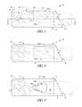
- FIG. 5is a longitudinal cross-sectional view of a drive tool according to another embodiment
- FIG. 6is an end view of the proximal end of the drive tool of FIGS. 1 and 2 ;
- FIG. 7is a fragmentary cross-sectional view of the drive tool of FIG. 5 ;
- FIG. 8is a fragmentary cross-sectional view of a drive tool according to a further embodiment
- FIG. 9is a fragmentary cross-sectional view of a drive tool according to a further embodiment.
- FIG. 10is a side elevation view of a portion of a one-piece dental implant with a substantially coliner orientation between the abutment portion and the implant body portion;
- FIG. 11is a side elevation view of a portion of a one-piece dental implant with a substantially non-colinear, or angled, orientation between the abutment portion and the implant body portion;
- FIG. 12is a fragmentary cross-sectional view of the drive tool of FIG. 5 ;
- FIG. 13is a fragmentary cross-sectional view of a drive tool according to a still further embodiment.
- FIG. 14is an end view of the proximal end of the drive tool of FIG. 9 .
- FIGS. 1-3show drive tool 10 according to one embodiment of the present invention, including an elongate body 12 having proximal end 14 and distal end 16 .
- proximal and distalmean closest to and furthest from a patient's maxilla or mandible, respectively, during use of drive tool 10 .
- Proximal end 14 of drive tool 10includes opening 18 which defines a cavity 20 , shown in FIGS. 2 and 3 .
- Cavity 20is sized to accept orthopedic screws such as dental implants 22 and 24 , shown in FIGS. 10 and 11 , respectively, each of which include a body portion and a head or abutment portion.
- the drive tools disclosed hereinare described in the context of use with dental implants, the drive tools may also find application with other types of orthopedic screws, such as internal or external fixation screws in trauma systems, and pedicle screws in spinal systems, for example.
- cavity 20 of elongate body 12is divided into two portions, proximal portion 26 and distal portion 28 .
- outer surface 30 of drive tool 10includes radial opening 32 .
- Radial opening 32defines passageway 34 which is angled to intersect cavity 20 at distal portion 28 of cavity 20 to provide a clearance space for receipt of certain angled orthopedic screws as described below.
- Passageway 34 and cavity 20may also include internal surfaces which substantially correspond to the external profiles of head portions 36 and 38 of dental implants 22 and 24 , shown in FIGS. 10 and 11 and described in further detail below.
- Cavity 20also includes non-rotational engagement structure, such as flat drive surfaces 44 and 46 , which engage corresponding non-rotational structure of implants 22 and 24 , such as flat portions 40 and 42 thereof, respectively, thereby rotationally locking and substantially prohibiting relative rotational motion between drive tool 10 and dental implants 22 and 24 , as described below.
- non-rotational engagement structuresuch as flat drive surfaces 44 and 46 , which engage corresponding non-rotational structure of implants 22 and 24 , such as flat portions 40 and 42 thereof, respectively, thereby rotationally locking and substantially prohibiting relative rotational motion between drive tool 10 and dental implants 22 and 24 , as described below.
- distal end 16 of drive tool 10may include one or more drive fittings, such as external polygonal fitting 48 , which in one embodiment includes four substantially flat walls 49 together defining a square cross-section, and internal polygonal fitting 50 , which in one embodiment includes six substantially flat walls 51 together defining a hexagonal cross-section.
- the number of walls of external polygonal fitting 48 and internal polygonal fitting 50may be varied.
- External polygonal fitting 48may be engaged by a driving instrument (not shown), such as a ratchet wrench or a drill, for example, to apply rotational torque to drive tool 10 .
- External polygonal fitting 48includes curved surfaces 52 between adjacent walls 49 thereof, which facilitate the engagement of the driving instrument with drive tool 10 .
- Internal polygonal fitting 50also includes broach relief 56 , which facilitates the manufacture of cavity 54 by accepting an accumulation of debris during broaching of cavity 54 .
- Internal polygonal fitting 50is capable of accepting a different type of driving instrument than internal polygonal fitting 48 to apply driving torque to drive tool 10 .
- annular collar 58is disposed adjacent to polygonal fitting 48 , which, together with annular flange 60 , forms the sidewalls of an annular groove 62 which facilitates handling and manipulation of drive tool 10 .
- Annular collar 58 and annular flange 60include flat sections 64 , 66 , respectively, which provide a visual indication to the surgeon when drive tool 10 is correctly aligned with dental implants 22 and 24 .
- FIGS. 10 and 11show exemplary embodiments of dental implants 22 and 24 having body portions 68 and 70 and abutment portions or head portions 36 and 38 , respectively, which are receivable within opening 18 of drive tool 10 .
- Body portions 68 and 70partially shown in FIGS. 10 and 11 , are externally threaded to facilitate implantation in the mandible or maxilla.
- Head portions 36 and 38include channels 72 and 74 and flat portions 40 and 42 , respectively.
- Channels 72 and 74are configured for receipt of a coping (not shown) to allow a dentist to take impressions in order to create a dental restoration.
- Dental implants 22 and 24also include margins 76 and 78 which may abut annular rim 80 of drive tool 10 when head portions 36 and 38 of implants 22 and 24 , respectively, are received within cavity 20 of drive tool 10 .
- margins 76 and 78 and annular rim 80are separated by a small distance, such as 0.25 inches, for example.
- head portion 36 of implant 22is non-angled, or has an angle of 0°, wherein head portion 36 includes a longitudinal axis A 2 which is substantially colinear with longitudinal axis A 1 of body portion 68 .
- head portion 38 of implant 24is angled, wherein head portion 38 includes a longitudinal axis A 2 which is angled with respect to, or divergent from, longitudinal axis A 1 of body portion 70 by an angle A 3 .
- flat portions 40 and 42are engaged by drive surfaces 44 and 46 of drive tool 10 upon insertion of head portions 36 and 38 into cavity 20 of drive tool 10 , substantially prohibiting relative rotation between dental implants 22 and 24 and drive tool 10 and thereby allowing rotational torque to be imparted to implants 22 and 24 via drive tool 10 .
- the non-rotational engagement structure of drive tool 10allows for substantial. prohibition of relative rotation between drive tool 10 and implants which have heads with different angular orientations with respect to the implant bodies, such as implants 22 and 24 .
- the end of head portion 38 of implant 24may be accommodated within channel 34 of cavity 20 of drive tool 10 .
- FIG. 3also depicts the longitudinal axis A 1 of the body of implants 22 and 24 , and the axis A 2 of the head portion 38 of implant 24 .
- a 2diverges from A 1 by acute angle A 3 .
- the axes of the cavity 20 and channel 34generally correspond to the axes of the implants 22 and 24 .
- FIG. 3also illustrates a wall 114 extending from a coronal wall 115 of cavity 20 .
- the wall 114extends outwardly from Axis A 1 generally at an angle corresponding to acute angle A 3 to accommodate angled head portion 38 .
- FIGS. 5 and 7depict drive tool 82 according to another embodiment. Except as described below, drive tool 82 of FIGS. 5 and 7 is substantially identical to drive tool 10 of FIGS. 1-3 discussed above, and identical reference numerals will be used to designate identical or substantially identical features therebetween.
- Proximal end 14 of elongate body 12 of drive tool 82has opening 18 defining cavity 84 , which may include drive surfaces, such as drive surfaces 44 and 46 of drive tool 10 for engaging corresponding drive surfaces of the dental implants.
- Cavity 84is divided into two portions, proximal portion 86 and distal portion 88 .
- Outer diameter 30includes radial opening 32 defining passageway 34 , which intersects cavity 84 at distal portion 88 .
- cavity 84allows for drive tool 78 to accept orthopedic screws having an angled head portion substantially non-colinear with the body portion thereof, such as dental implant 24 described above, for example.
- Portions 86 , 88 of cavity 84define a substantially lesser volume than portions 26 , 28 of drive tool 10 .
- opening 18defines an interior configuration of cavity 84 which is dimensioned to closely receive head portion 38 of implant 24 to closely maintain the alignment and positioning of head portion 36 of implant 24 within cavity 84 .
- FIG. 8depicts drive tool 90 according to another embodiment. Except as described below, drive tool 90 of FIG. 8 is substantially identical to drive tool 82 of FIGS. 1-3 discussed above, and identical reference numerals will be used to designate identical or substantially identical features therebetween.
- Drive tool 90has proximal end 14 having opening 18 defining cavity 84 , which may include drive surfaces, such as drive surfaces 44 and 46 of drive tool 10 , for engaging corresponding drive surfaces of the dental implants.
- Drive tool 90is identical to drive tool 10 , shown in FIGS.
- drive tool 90may accept implants having head portions within a more limited range of angular orientations with respect to the body portions of the implants than the implants which may be accepted by drive tool 10 .
- FIGS. 9 and 14depict drive tool 92 according to another embodiment. Except as described below, drive tool 92 of FIG. 9 is substantially identical to drive tool 10 of FIGS. 1-3 discussed above, and identical reference numerals will be used to designate identical or substantially identical features therebetween.
- Drive tool 92includes elongate body 12 having proximal end 14 with opening 18 defining a cavity 94 , which may include drive surfaces, such as drive surfaces 44 and 46 of drive tool 10 , for engaging corresponding drive surfaces of the dental implants. Cavity 94 is divided into two portions, including proximal portion 96 and distal portion 98 .
- Distal portion 96 of cavity 94 of drive tool 92is further defined by a plurality of wall sections 100 defining progressively decreasing interior volumes from the proximal end 16 towards the distal end 14 of drive tool 92 .
- Wall sections 100have a stepped configuration defining perimeters that are substantially similar to the dimensions of head portion 36 of dental implant 22 , shown in FIG. 10 , and the longitudinal axes of some of wall sections 100 may be shaped to be offset from the longitudinal axes of other wall sections 100 in order to more closely dimension cavity 94 to conform to the profile of the head portion of an implant.
- wall section 100 Ais offset from longitudinal axis A of drive tool 92
- wall section 100 Bwhich is substantially aligned with longitudinal axis A.
- cavity 94 of drive tool 92to accept an orthopedic screw having a specific angular orientation of the head portion with respect to the body portion of the dental implant, such as dental implant 22 as described above.
- wall sections 100define an interior configuration of cavity 94 which is dimensioned to closely receive head portion 36 of implant 22 to maintain the alignment and positioning of head portion 36 of implant 22 within cavity 94 .
- FIG. 13depicts another exemplary embodiment as drive tool 102 .
- Drive tool 102 of FIG. 13is substantially identical to drive tool 10 of FIG. 1 discussed above, and identical reference numerals will be used to designate identical or substantially identical features therebetween.
- Drive tool 102is formed by elongate body 12 having proximal end 14 with opening 18 defining cavity 104 .
- Cavity 104is further defined by interior walls defining first and second portions 106 and 107 of cavity 104 having internal shapes that are substantially identical to the exterior profiles of head portions 36 and 38 of dental implants 22 and 24 , respectively, with first and second portions 106 and 107 of cavity 104 terminating in frustoconical shapes substantially similar to tips 108 , 110 of dental implants 22 , 24 , respectively.
- a wall 111including a first side 112 and a second side 113 , can be located between first portion 106 and second portion 107 .
- cavity 104may lack drive surfaces 44 and 46 , wherein rotational torque is imparted to head portions 36 and 38 of dental implants 22 and 24 via the geometric fit between first and second portions 106 and 107 of cavity 104 and head portions 36 and 38 of dental implants 22 and 24 , respectively.
Landscapes
- Health & Medical Sciences (AREA)
- Orthopedic Medicine & Surgery (AREA)
- Life Sciences & Earth Sciences (AREA)
- Surgery (AREA)
- General Health & Medical Sciences (AREA)
- Veterinary Medicine (AREA)
- Public Health (AREA)
- Animal Behavior & Ethology (AREA)
- Heart & Thoracic Surgery (AREA)
- Medical Informatics (AREA)
- Molecular Biology (AREA)
- Biomedical Technology (AREA)
- Engineering & Computer Science (AREA)
- Nuclear Medicine, Radiotherapy & Molecular Imaging (AREA)
- Neurology (AREA)
- Oral & Maxillofacial Surgery (AREA)
- Dentistry (AREA)
- Epidemiology (AREA)
- Dental Prosthetics (AREA)
Abstract
Description
Claims (16)
Priority Applications (1)
| Application Number | Priority Date | Filing Date | Title |
|---|---|---|---|
| US11/532,291US8771285B2 (en) | 2006-09-15 | 2006-09-15 | Drive tool for orthopedic screws |
Applications Claiming Priority (1)
| Application Number | Priority Date | Filing Date | Title |
|---|---|---|---|
| US11/532,291US8771285B2 (en) | 2006-09-15 | 2006-09-15 | Drive tool for orthopedic screws |
Publications (2)
| Publication Number | Publication Date |
|---|---|
| US20080097458A1 US20080097458A1 (en) | 2008-04-24 |
| US8771285B2true US8771285B2 (en) | 2014-07-08 |
Family
ID=39339798
Family Applications (1)
| Application Number | Title | Priority Date | Filing Date |
|---|---|---|---|
| US11/532,291Expired - Fee RelatedUS8771285B2 (en) | 2006-09-15 | 2006-09-15 | Drive tool for orthopedic screws |
Country Status (1)
| Country | Link |
|---|---|
| US (1) | US8771285B2 (en) |
Cited By (2)
| Publication number | Priority date | Publication date | Assignee | Title |
|---|---|---|---|---|
| US20170252130A1 (en)* | 2014-07-17 | 2017-09-07 | Southern Implants (Pty) Ltd | Overdenture Retention Implant and Apparatus for Installing it |
| US20220087786A1 (en)* | 2019-01-22 | 2022-03-24 | Z-Systems AG | Occlusal screw, dental implant system and set |
Families Citing this family (10)
| Publication number | Priority date | Publication date | Assignee | Title |
|---|---|---|---|---|
| USD611511S1 (en)* | 2006-03-22 | 2010-03-09 | Bti, I+D, S.L. | Ridge expander drill |
| US20090240291A1 (en)* | 2008-03-24 | 2009-09-24 | K2M, Inc. | Breached pedicle screw |
| US9693799B2 (en) | 2009-09-17 | 2017-07-04 | Pilofocus, Inc. | System and method for aligning hair follicle |
| AU2010295447C1 (en) | 2009-09-17 | 2014-11-27 | Carlos K. Wesley | Hair restoration surgery |
| US9314082B2 (en)* | 2009-09-17 | 2016-04-19 | Pilofocus, Inc. | System and method for extraction of hair follicle |
| USD668764S1 (en)* | 2011-01-24 | 2012-10-09 | Straumann Holding Ag | Portion of a dental implant |
| HK1201134A1 (en) | 2011-10-17 | 2015-08-28 | 皮洛福克斯有限公司 | Hair restoration |
| FR2997007B1 (en)* | 2012-10-19 | 2015-10-30 | Teknimed | SYSTEM FOR FIXING OSTEOSYNTHESIS EQUIPMENT |
| IL230438A (en) | 2014-01-13 | 2015-07-30 | Boris Fridzon | Conical connection abutment for a dental implant |
| IT201600068763A1 (en)* | 2016-07-01 | 2018-01-01 | Errecieffe S R L | TOOL SET WITH MONOPHASIC DENTAL SYSTEMS WITH INCLINED AXIS |
Citations (38)
| Publication number | Priority date | Publication date | Assignee | Title |
|---|---|---|---|---|
| US916951A (en)* | 1908-05-19 | 1909-03-30 | Ohio Malleable Iron Company | Wrench. |
| US1321776A (en)* | 1919-11-11 | Wbeztch | ||
| US1346061A (en)* | 1920-02-24 | 1920-07-06 | Rosenberg Sidnez Clarence | Wrench |
| US4258596A (en)* | 1978-01-18 | 1981-03-31 | Southco, Inc. | Tamper-resistant fastener |
| US4380942A (en)* | 1981-06-25 | 1983-04-26 | Fenton John W | Torque-transmitting tool assembly |
| GB2141803A (en) | 1983-05-26 | 1985-01-03 | Decaut Et Btr Reunis Soc | Screwing device |
| US4955811A (en) | 1988-06-23 | 1990-09-11 | Implant Innovations, Inc. | Non-rotational single-tooth prosthodontic restoration |
| US5009596A (en) | 1987-04-22 | 1991-04-23 | Astra Meditec Aktiebolag | Device for fixing a dental prothesis |
| US5065649A (en) | 1990-08-21 | 1991-11-19 | Bulter Manufacturing Company | Device for holding fasteners |
| US5074174A (en)* | 1989-09-02 | 1991-12-24 | Dae Sam Co., Ltd. | Socket wrench |
| US5171117A (en)* | 1991-10-16 | 1992-12-15 | Textron Inc. | Fastener with multilobular internal recess and tool entry ramps |
| US5269208A (en) | 1992-08-14 | 1993-12-14 | James D. Sperling | Tamper-proof fastener and a driver tool therefor |
| US5484440A (en) | 1992-11-03 | 1996-01-16 | Zimmer, Inc. | Bone screw and screwdriver |
| US5538428A (en) | 1994-04-05 | 1996-07-23 | Attachments International | Packing delivery system for dental implant and method |
| US5636990A (en)* | 1994-03-15 | 1997-06-10 | Stemmann; Hartmut | Device for securing an insert on an implant |
| US5643320A (en) | 1995-03-13 | 1997-07-01 | Depuy Inc. | Soft tissue anchor and method |
| US5690489A (en) | 1995-07-26 | 1997-11-25 | Carchidi; Joseph Edward | Delivery and drive tool for threaded members and method for use |
| US5755575A (en) | 1996-08-16 | 1998-05-26 | Sulzer Calcitek, Inc. | Dental implant delivery system and method |
| US5927979A (en) | 1994-12-15 | 1999-07-27 | Biohorizons Implants Systems, Inc. | Abutment-mount system for dental implants |
| US5944525A (en)* | 1997-03-11 | 1999-08-31 | Ura; Robert S. | Dental implant and method and apparatus for installing the same |
| US5974917A (en) | 1997-11-21 | 1999-11-02 | Way; Michael A. | MIG welding gun contact tip changing tool |
| US6158310A (en)* | 1999-05-24 | 2000-12-12 | Textron Inc. | Drive system having a strengthened drive system member for resisting torsional stresses |
| US6159008A (en) | 1998-07-13 | 2000-12-12 | Steri-Oss Inc. | Implant carrier with gripping fingers |
| US6247933B1 (en) | 1999-12-10 | 2001-06-19 | Sulzer Dental Inc. | Dental implant delivery system |
| US6314841B1 (en)* | 2000-03-27 | 2001-11-13 | Larry K. Burk | Multi-purpose hand tool |
| US6343531B2 (en) | 1997-11-20 | 2002-02-05 | Macropore, Inc. | High-torque resorbable screws |
| US6389934B1 (en) | 2000-06-07 | 2002-05-21 | Huey-Wen Yang Yen | Two directional operation wrench |
| US6416324B1 (en) | 1999-12-10 | 2002-07-09 | Sulzer Dental Inc. | One step dental implant delivery system |
| US6454567B1 (en) | 2001-04-23 | 2002-09-24 | Ace Surgical Supply Co., Inc. | Dental implant delivery and drive tool |
| US6502483B1 (en)* | 2001-08-29 | 2003-01-07 | Tum Yeto, Inc. | Combination skateboard tool |
| US20030054319A1 (en) | 2001-09-17 | 2003-03-20 | Christopher Gervais | Impression post and temporary abutment and method of making dental restoration |
| US20030054318A1 (en) | 2001-09-17 | 2003-03-20 | Christopher Gervais | Torque limiting implant drive system |
| US20030224327A1 (en) | 2002-06-03 | 2003-12-04 | Aziz Constantino | Dental implant installation method and device |
| US20040101807A1 (en)* | 2002-11-13 | 2004-05-27 | Porter Stephan S. | Dental implant system |
| US20040137406A1 (en)* | 1999-08-17 | 2004-07-15 | Don Kennard | Immediate provisional implant |
| US20040175673A1 (en)* | 2003-03-05 | 2004-09-09 | Albert Zickman | Dental implant system |
| US6827575B1 (en) | 1999-03-18 | 2004-12-07 | Nobel Biocare Ab | Method, arrangement and use for applying a spacer to an implant by means of a screw |
| US20070082320A1 (en)* | 2005-10-10 | 2007-04-12 | Faus Badia Vicente G | Angled implant prosthesis and method of use thereof |
- 2006
- 2006-09-15USUS11/532,291patent/US8771285B2/ennot_activeExpired - Fee Related
Patent Citations (40)
| Publication number | Priority date | Publication date | Assignee | Title |
|---|---|---|---|---|
| US1321776A (en)* | 1919-11-11 | Wbeztch | ||
| US916951A (en)* | 1908-05-19 | 1909-03-30 | Ohio Malleable Iron Company | Wrench. |
| US1346061A (en)* | 1920-02-24 | 1920-07-06 | Rosenberg Sidnez Clarence | Wrench |
| US4258596A (en)* | 1978-01-18 | 1981-03-31 | Southco, Inc. | Tamper-resistant fastener |
| US4380942A (en)* | 1981-06-25 | 1983-04-26 | Fenton John W | Torque-transmitting tool assembly |
| GB2141803A (en) | 1983-05-26 | 1985-01-03 | Decaut Et Btr Reunis Soc | Screwing device |
| US5009596A (en) | 1987-04-22 | 1991-04-23 | Astra Meditec Aktiebolag | Device for fixing a dental prothesis |
| US4955811A (en) | 1988-06-23 | 1990-09-11 | Implant Innovations, Inc. | Non-rotational single-tooth prosthodontic restoration |
| US5074174A (en)* | 1989-09-02 | 1991-12-24 | Dae Sam Co., Ltd. | Socket wrench |
| US5065649A (en) | 1990-08-21 | 1991-11-19 | Bulter Manufacturing Company | Device for holding fasteners |
| US5171117A (en)* | 1991-10-16 | 1992-12-15 | Textron Inc. | Fastener with multilobular internal recess and tool entry ramps |
| US5269208A (en) | 1992-08-14 | 1993-12-14 | James D. Sperling | Tamper-proof fastener and a driver tool therefor |
| US5484440A (en) | 1992-11-03 | 1996-01-16 | Zimmer, Inc. | Bone screw and screwdriver |
| US5636990A (en)* | 1994-03-15 | 1997-06-10 | Stemmann; Hartmut | Device for securing an insert on an implant |
| US5538428A (en) | 1994-04-05 | 1996-07-23 | Attachments International | Packing delivery system for dental implant and method |
| US5927979A (en) | 1994-12-15 | 1999-07-27 | Biohorizons Implants Systems, Inc. | Abutment-mount system for dental implants |
| US5643320A (en) | 1995-03-13 | 1997-07-01 | Depuy Inc. | Soft tissue anchor and method |
| US5690489A (en) | 1995-07-26 | 1997-11-25 | Carchidi; Joseph Edward | Delivery and drive tool for threaded members and method for use |
| US5690489C1 (en) | 1995-07-26 | 2002-04-09 | Ace Surgical Supply Co Inc | Delivery and drive tool for threaded members and method for use |
| US5755575A (en) | 1996-08-16 | 1998-05-26 | Sulzer Calcitek, Inc. | Dental implant delivery system and method |
| US5944525A (en)* | 1997-03-11 | 1999-08-31 | Ura; Robert S. | Dental implant and method and apparatus for installing the same |
| US6343531B2 (en) | 1997-11-20 | 2002-02-05 | Macropore, Inc. | High-torque resorbable screws |
| US5974917A (en) | 1997-11-21 | 1999-11-02 | Way; Michael A. | MIG welding gun contact tip changing tool |
| US6315562B1 (en) | 1998-07-13 | 2001-11-13 | Nobel Biocare Usa, Inc. | Implant carrier with gripping fingers |
| US6159008A (en) | 1998-07-13 | 2000-12-12 | Steri-Oss Inc. | Implant carrier with gripping fingers |
| US6827575B1 (en) | 1999-03-18 | 2004-12-07 | Nobel Biocare Ab | Method, arrangement and use for applying a spacer to an implant by means of a screw |
| US6158310A (en)* | 1999-05-24 | 2000-12-12 | Textron Inc. | Drive system having a strengthened drive system member for resisting torsional stresses |
| US20040137406A1 (en)* | 1999-08-17 | 2004-07-15 | Don Kennard | Immediate provisional implant |
| US6416324B1 (en) | 1999-12-10 | 2002-07-09 | Sulzer Dental Inc. | One step dental implant delivery system |
| US6247933B1 (en) | 1999-12-10 | 2001-06-19 | Sulzer Dental Inc. | Dental implant delivery system |
| US6314841B1 (en)* | 2000-03-27 | 2001-11-13 | Larry K. Burk | Multi-purpose hand tool |
| US6389934B1 (en) | 2000-06-07 | 2002-05-21 | Huey-Wen Yang Yen | Two directional operation wrench |
| US6454567B1 (en) | 2001-04-23 | 2002-09-24 | Ace Surgical Supply Co., Inc. | Dental implant delivery and drive tool |
| US6502483B1 (en)* | 2001-08-29 | 2003-01-07 | Tum Yeto, Inc. | Combination skateboard tool |
| US20030054318A1 (en) | 2001-09-17 | 2003-03-20 | Christopher Gervais | Torque limiting implant drive system |
| US20030054319A1 (en) | 2001-09-17 | 2003-03-20 | Christopher Gervais | Impression post and temporary abutment and method of making dental restoration |
| US20030224327A1 (en) | 2002-06-03 | 2003-12-04 | Aziz Constantino | Dental implant installation method and device |
| US20040101807A1 (en)* | 2002-11-13 | 2004-05-27 | Porter Stephan S. | Dental implant system |
| US20040175673A1 (en)* | 2003-03-05 | 2004-09-09 | Albert Zickman | Dental implant system |
| US20070082320A1 (en)* | 2005-10-10 | 2007-04-12 | Faus Badia Vicente G | Angled implant prosthesis and method of use thereof |
Non-Patent Citations (2)
| Title |
|---|
| Product Brochure, Sulzer Medica Sulzer Calcitek Inc., Spline Dental Implant Interface, 2000. |
| Product Catalog, Swede-Vent, The external hex system from Dentsply, Dentsply Implant, 1992. |
Cited By (2)
| Publication number | Priority date | Publication date | Assignee | Title |
|---|---|---|---|---|
| US20170252130A1 (en)* | 2014-07-17 | 2017-09-07 | Southern Implants (Pty) Ltd | Overdenture Retention Implant and Apparatus for Installing it |
| US20220087786A1 (en)* | 2019-01-22 | 2022-03-24 | Z-Systems AG | Occlusal screw, dental implant system and set |
Also Published As
| Publication number | Publication date |
|---|---|
| US20080097458A1 (en) | 2008-04-24 |
Similar Documents
| Publication | Publication Date | Title |
|---|---|---|
| US8771285B2 (en) | Drive tool for orthopedic screws | |
| US9039415B2 (en) | Connecting screw for a dental implant | |
| US20200229904A1 (en) | Dental implant | |
| AU2006259478B2 (en) | Dental restorative system and components | |
| EP0376944B1 (en) | A tool for a prosthetic part | |
| US20070059666A1 (en) | Dental implant system | |
| US8734155B2 (en) | Dental implant system and method | |
| US5685715A (en) | Self-indexing transfer impression coping | |
| US8632336B2 (en) | Tooth implant | |
| US8430668B2 (en) | Dental restorative system and components | |
| RU2615125C2 (en) | Dental component, dental implantable component and dental implant | |
| US20020110783A1 (en) | Dental implant and tool and method for effecting a dental restoration using the same | |
| US20090298014A1 (en) | Dental Implant | |
| JP2004529698A (en) | Implant | |
| US20120164599A1 (en) | Dental fixture, a dental component and a dental implant assembly | |
| CA2600280A1 (en) | Screw-in enossal dental implant | |
| US20090305191A1 (en) | Failsafe Installation Tool For Dental Implants | |
| US20100015571A1 (en) | Flexible Abutment For Use With A Dental Implant | |
| CN113573661B (en) | Tool assembly for installing dental prosthesis and installation method | |
| US20220395357A1 (en) | Arrangement with a tool and with a fastening means, and method for fastening a fastening means | |
| US20120129130A1 (en) | Torque wrench and kit for implant dentistry | |
| HK1098658A (en) | Orthodontic bone screw |
Legal Events
| Date | Code | Title | Description |
|---|---|---|---|
| AS | Assignment | Owner name:ZIMMER DENTAL, INC., CALIFORNIA Free format text:ASSIGNMENT OF ASSIGNORS INTEREST;ASSIGNORS:DONAHOE, RYAN M.;JOHNSON, JAMES I.;REEL/FRAME:018352/0621;SIGNING DATES FROM 20060906 TO 20061002 Owner name:ZIMMER DENTAL, INC., CALIFORNIA Free format text:ASSIGNMENT OF ASSIGNORS INTEREST;ASSIGNORS:DONAHOE, RYAN M.;JOHNSON, JAMES I.;SIGNING DATES FROM 20060906 TO 20061002;REEL/FRAME:018352/0621 | |
| FEPP | Fee payment procedure | Free format text:PAYOR NUMBER ASSIGNED (ORIGINAL EVENT CODE: ASPN); ENTITY STATUS OF PATENT OWNER: LARGE ENTITY Free format text:PAYER NUMBER DE-ASSIGNED (ORIGINAL EVENT CODE: RMPN); ENTITY STATUS OF PATENT OWNER: LARGE ENTITY | |
| STCF | Information on status: patent grant | Free format text:PATENTED CASE | |
| CC | Certificate of correction | ||
| MAFP | Maintenance fee payment | Free format text:PAYMENT OF MAINTENANCE FEE, 4TH YEAR, LARGE ENTITY (ORIGINAL EVENT CODE: M1551) Year of fee payment:4 | |
| FEPP | Fee payment procedure | Free format text:MAINTENANCE FEE REMINDER MAILED (ORIGINAL EVENT CODE: REM.); ENTITY STATUS OF PATENT OWNER: LARGE ENTITY | |
| AS | Assignment | Owner name:JPMORGAN CHASE BANK, N.A., AS ADMINISTRATIVE AGENT, NEW YORK Free format text:SECURITY INTEREST;ASSIGNORS:BIOMET 3I, LLC;EBI, LLC;ZIMMER BIOMET SPINE, INC.;AND OTHERS;REEL/FRAME:059293/0213 Effective date:20220228 | |
| LAPS | Lapse for failure to pay maintenance fees | Free format text:PATENT EXPIRED FOR FAILURE TO PAY MAINTENANCE FEES (ORIGINAL EVENT CODE: EXP.); ENTITY STATUS OF PATENT OWNER: LARGE ENTITY | |
| STCH | Information on status: patent discontinuation | Free format text:PATENT EXPIRED DUE TO NONPAYMENT OF MAINTENANCE FEES UNDER 37 CFR 1.362 | |
| FP | Lapsed due to failure to pay maintenance fee | Effective date:20220708 |