US8771269B2 - RF energy delivery system and method - Google Patents
RF energy delivery system and methodDownload PDFInfo
- Publication number
- US8771269B2 US8771269B2US12/117,596US11759608AUS8771269B2US 8771269 B2US8771269 B2US 8771269B2US 11759608 AUS11759608 AUS 11759608AUS 8771269 B2US8771269 B2US 8771269B2
- Authority
- US
- United States
- Prior art keywords
- radio frequency
- monopolar
- bipolar
- energy
- power
- Prior art date
- Legal status (The legal status is an assumption and is not a legal conclusion. Google has not performed a legal analysis and makes no representation as to the accuracy of the status listed.)
- Active, expires
Links
Images


Classifications
- A—HUMAN NECESSITIES
- A61—MEDICAL OR VETERINARY SCIENCE; HYGIENE
- A61B—DIAGNOSIS; SURGERY; IDENTIFICATION
- A61B18/00—Surgical instruments, devices or methods for transferring non-mechanical forms of energy to or from the body
- A61B18/04—Surgical instruments, devices or methods for transferring non-mechanical forms of energy to or from the body by heating
- A61B18/12—Surgical instruments, devices or methods for transferring non-mechanical forms of energy to or from the body by heating by passing a current through the tissue to be heated, e.g. high-frequency current
- A61B18/14—Probes or electrodes therefor
- A61B18/1492—Probes or electrodes therefor having a flexible, catheter-like structure, e.g. for heart ablation
- A—HUMAN NECESSITIES
- A61—MEDICAL OR VETERINARY SCIENCE; HYGIENE
- A61B—DIAGNOSIS; SURGERY; IDENTIFICATION
- A61B18/00—Surgical instruments, devices or methods for transferring non-mechanical forms of energy to or from the body
- A61B18/04—Surgical instruments, devices or methods for transferring non-mechanical forms of energy to or from the body by heating
- A61B18/12—Surgical instruments, devices or methods for transferring non-mechanical forms of energy to or from the body by heating by passing a current through the tissue to be heated, e.g. high-frequency current
- A61B18/1206—Generators therefor
- A—HUMAN NECESSITIES
- A61—MEDICAL OR VETERINARY SCIENCE; HYGIENE
- A61B—DIAGNOSIS; SURGERY; IDENTIFICATION
- A61B18/00—Surgical instruments, devices or methods for transferring non-mechanical forms of energy to or from the body
- A61B2018/00053—Mechanical features of the instrument of device
- A61B2018/00214—Expandable means emitting energy, e.g. by elements carried thereon
- A—HUMAN NECESSITIES
- A61—MEDICAL OR VETERINARY SCIENCE; HYGIENE
- A61B—DIAGNOSIS; SURGERY; IDENTIFICATION
- A61B18/00—Surgical instruments, devices or methods for transferring non-mechanical forms of energy to or from the body
- A61B2018/00315—Surgical instruments, devices or methods for transferring non-mechanical forms of energy to or from the body for treatment of particular body parts
- A61B2018/00345—Vascular system
- A61B2018/00351—Heart
- A61B2018/00375—Ostium, e.g. ostium of pulmonary vein or artery
- A—HUMAN NECESSITIES
- A61—MEDICAL OR VETERINARY SCIENCE; HYGIENE
- A61B—DIAGNOSIS; SURGERY; IDENTIFICATION
- A61B18/00—Surgical instruments, devices or methods for transferring non-mechanical forms of energy to or from the body
- A61B18/04—Surgical instruments, devices or methods for transferring non-mechanical forms of energy to or from the body by heating
- A61B18/12—Surgical instruments, devices or methods for transferring non-mechanical forms of energy to or from the body by heating by passing a current through the tissue to be heated, e.g. high-frequency current
- A61B18/14—Probes or electrodes therefor
- A61B2018/1405—Electrodes having a specific shape
- A61B2018/1407—Loop
- A—HUMAN NECESSITIES
- A61—MEDICAL OR VETERINARY SCIENCE; HYGIENE
- A61B—DIAGNOSIS; SURGERY; IDENTIFICATION
- A61B18/00—Surgical instruments, devices or methods for transferring non-mechanical forms of energy to or from the body
- A61B18/04—Surgical instruments, devices or methods for transferring non-mechanical forms of energy to or from the body by heating
- A61B18/12—Surgical instruments, devices or methods for transferring non-mechanical forms of energy to or from the body by heating by passing a current through the tissue to be heated, e.g. high-frequency current
- A61B18/14—Probes or electrodes therefor
- A61B2018/1467—Probes or electrodes therefor using more than two electrodes on a single probe
- A—HUMAN NECESSITIES
- A61—MEDICAL OR VETERINARY SCIENCE; HYGIENE
- A61B—DIAGNOSIS; SURGERY; IDENTIFICATION
- A61B18/00—Surgical instruments, devices or methods for transferring non-mechanical forms of energy to or from the body
- A61B18/04—Surgical instruments, devices or methods for transferring non-mechanical forms of energy to or from the body by heating
- A61B18/12—Surgical instruments, devices or methods for transferring non-mechanical forms of energy to or from the body by heating by passing a current through the tissue to be heated, e.g. high-frequency current
- A61B18/14—Probes or electrodes therefor
- A61B2018/1475—Electrodes retractable in or deployable from a housing
Definitions
- the present inventionrelates generally to ablation systems and methods for performing targeted tissue ablation in a patient.
- the present inventionprovides radiofrequency (RF) energy generators that create safe, precision lesions in tissue such as cardiac tissue.
- RFradiofrequency
- Tissue ablationis used in numerous medical procedures to treat a patient.
- Ablationcan be performed to remove or denature undesired tissue such as cancer cells.
- Ablation proceduresmay also involve the modification of the tissue without removal, such as to stop electrical propagation through the tissue in patients with an arrhythmia condition.
- the ablationis performed by passing energy, such as electrical energy, through one or more electrodes and causing the tissue in contact with the electrodes to heat up to an ablative temperature.
- Ablation procedurescan be performed on patients with atrial fibrillation by ablating tissue in the heart.
- Mammalian organ functiontypically occurs through the transmission of electrical impulses from one tissue to another. A disturbance of such electrical transmission may lead to organ malfunction.
- One particular area where electrical impulse transmission is critical for proper organ functionis in the heart. Normal sinus rhythm of the heart begins with the sinus node generating an electrical impulse that is propagated uniformly across the right and left atria to the atrioventricular node. Atrial contraction leads to the pumping of blood into the ventricles in a manner synchronous with the pulse.
- Atrial fibrillationrefers to a type of cardiac arrhythmia where there is disorganized electrical conduction in the atria causing rapid uncoordinated contractions that result in ineffective pumping of blood into the ventricle and a lack of synchrony.
- the atrioventricular nodereceives electrical impulses from numerous locations throughout the atria instead of only from the sinus node. This overwhelms the atrioventricular node into producing an irregular and rapid heartbeat.
- bloodpools in the atria that increases a risk for blood clot formation.
- the major risk factors for atrial fibrillationinclude age, coronary artery disease, rheumatic heart disease, hypertension, diabetes, and thyrotoxicosis. Atrial fibrillation affects 7% of the population over age 65.
- Atrial fibrillation treatment optionsare limited. Lifestyle change only assists individuals with lifestyle related atrial fibrillation. Medication therapy assists only in the management of atrial fibrillation symptoms, may present side effects more dangerous than atrial fibrillation, and fail to cure atrial fibrillation. Electrical cardioversion attempts to restore sinus rhythm but has a high recurrence rate. In addition, if there is a blood clot in the atria, cardioversion may cause the clot to leave the heart and travel to the brain or to some other part of the body, which may lead to stroke. What are needed are new methods for treating atrial fibrillation and other conditions involving disorganized electrical conduction.
- RF energy generators and ablation catheter systems and methodswhich map and ablate large surface areas within the heart chambers of a patient, with one or few catheter placements. Any electrocardiogram signal site (e.g. a site with aberrant signals) or combination of multiple sites that are discovered with this placement may be ablated. In alternative embodiments, the RF generators and/or ablation catheters may be used to treat non-cardiac patient tissue, such as tumor tissue.
- the system and methodprovide maximum flexibility, efficacy and safety.
- the system and methodprovide independent delivery of monopolar and/or bipolar RF energy to multiple (e.g. 4, 8 or 12) user selectable electrodes.
- Monopolar energy deliveryprovides lesion depth and bipolar energy delivery provides lesion fill between selected electrodes.
- Sequential and/or simultaneous delivery of monopolar and bipolar RF energycan provide variable-depth linear lesions with a single or a reduced number of applications of energy.
- the system and methodprovide safe, precisely controlled delivery of RF energy to tissue.
- a constant voltage sourceis utilized for all pairs of RF outputs (channels) and adjustment of the phase angle of the applied (RF) voltage produces different ratios of simultaneous and/or cumulative monopolar and bipolar energy delivered such as to create varied length and depth lesions in the tissue of a patient.
- a varied voltage sourceis utilized for all pairs of RF outputs and adjustment of the voltage amplitude or other applied voltage property produces different ratios of simultaneous and/or cumulative monopolar and bipolar energy delivered such as to create varied length and depth lesions in the tissue of a patient.
- the duty cycle used during energy deliverymay be fixed, or alternatively it may be varied such as a configuration in which a minimal duty cycle is used which incrementally increases to reach a target tissue temperature.
- the phase shiftmay be fixed, such as fixed at 90° or 180° phase shift to create the bipolar energy.
- the RF generator of this embodimentincludes variable power supply circuits for each RF output.
- varying the average “on” time of bipolar and/or monopolar power deliveryis utilized for all pairs of RF outputs and adjustment of this average produces different ratios of simultaneous and/or cumulative monopolar and bipolar energy delivered such as to create varied length and depth lesions in the tissue of a patient.
- the ratio of bipolar fields (or combined monopolar-bipolar fields) to monopolar fieldsmay be adjusted to achieve a desired power level and/or bipolar-monopolar ratio.
- the duty cycle ratio within the bipolar fields (or combined monopolar-bipolar fields) and the monopolar fieldsmay be adjusted to achieve the desired power level and/or bipolar-monopolar ratio.
- the fields length of the bipolar fields (or combined monopolar-bipolar fields) and the monopolar fieldsmay be adjusted to achieve the desired power level and/or bipolar-monopolar ratio.
- the RF generators of the present inventionmay employ one or more energy delivery algorithms to control power delivery.
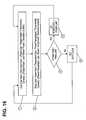
- an algorithmprovides energy at a fixed power, such as a maximum power, until the tissue to be ablated reaches a first temperature level. For temperatures above the first temperature level, power is delivered at a level determined by the actual tissue temperature. Target temperature levels and/or threshold temperatures may be adjustable by an operator of the system.
- an algorithmemploys a main control loop based on a power differential analysis and a secondary control loop based on a temperature differential analysis.
- the RF generators of the present inventionmay employ a multiplexing module which allows an operator of the system to selectively pair RF outputs from a group of three or more RF outputs to deliver bipolar energy between the selected pair.
- the system and methodinclude closed loop energy delivery for each RF output including a PID control loop which receives information from a thermocouple mounted proximate each electrode on the ablation catheter such as to provide closed loop energy delivery based on measured tissue temperature.
- Power deliverymay be duty cycle controlled to improve lesion creation efficiency, providing low power ablations.
- Duty cycle controlallows delivery of high peak powers while providing electrode cooling times during the off cycle.
- duty cycle power controlsimplifies design and control of multiple RF outputs utilizing different phase angles.
- Duty cycle energy deliveryalso improves temperature acquisition as data can be acquired during the off portion of the duty cycle (i.e., during the RF “quiet time”).
- the system and method including temperature acquisitionprovide fast, accurate and electrically-isolated temperature acquisition for all electrodes.
- Each catheter electrodemay include a small mass thermocouple.
- the system and methodprovide safe, controlled energy delivery.
- the RF generatorincludes a first set of ablation parameters that are utilized when a first form of ablation catheter is attached to the RF outputs and a second set of ablation parameters that are utilized when a second form of ablation catheter is attached to the RF outputs.
- the RF generatorincludes an improved EKG interface for connecting the RF outputs to an EKG diagnostic device.
- the electrodes of the ablation catheterare electrically attached to the RF outputs of the RF generator.
- the improved EKG interface of the present inventionattenuates the energy delivered to ablate tissue to a level to prevent damage to any attached EKG diagnostic device, yet allows EKG or other signals sensed by the electrodes to be transferred to the EKG diagnostic device with minimal attenuation of those signals.
- a system for performing an ablation procedureis described.
- one or more ablation cathetersare provided with an RF generator of the present invention.
- a remote controlis provided with the RF generator of the present invention.
- a radio frequency tissue ablation systemincluding a radio frequency generator.
- the generatorhas a radio frequency source, at least four independently controllable radio frequency outputs, a user interface and a controller configured to delivery radio frequency energy from the radio frequency source to the radio frequency outputs in one of at least two different output configurations in response to a configuration selection made through the user interface.
- the controlleris further configured to operate each output in either a monopolar mode or in a bipolar mode or possibly in a combination monopolar/bipolar mode, possibly in response to a configuration selection made through a user interface.
- the systemmay also include a ground pad connected to a ground source when the outputs are operated in both monopolar mode and bipolar mode.
- the controlleris further configured to deliver radio frequency energy from the radio frequency source to the radio frequency outputs in a plurality of successive time fields each having a period.
- the time fieldsmay have a duty cycle with a portion of the period when radio frequency energy is being delivered to the outputs and another portion of the period when radio frequency energy is not being delivered to the outputs.
- the controllermay be further configured to adjust the duty cycle in response to a configuration selection made through the user interface.
- at least one time field of the plurality of the successive time fieldsis monopolar for at least a portion of the period, and at least another time field of the successive time fields is bipolar for at least a portion of the period.
- the controllermay be configured to adjust a ratio of bipolar to monopolar time fields in response to a configuration selection made through the user interface.
- One time fieldmay be a combination monopolar/bipolar time field.
- the controllermay also be further configured to adjust a length of at least one time field in response to a configuration selection made through the user interface.
- the radio frequency sourceis a constant voltage source, and in some embodiments the radio frequency source is a variable voltage source, in which case the controller may be further configured to vary voltage amplitude in response to a configuration selection made through the user interface. In some embodiments the controller is further configured to adjust voltage phase angle of the RF source, possibly in response to a configuration selection made through the user interface. In some embodiments, the controller includes a time division multiplexor.
- the radio frequency generatorfurther includes an electrode tool interface configured to detect an identifier of a radio frequency electrode tool connected to the interface, the controller being configured to adjust radio frequency energy delivery parameters to an radio frequency electrode tool based on the identifier detected by the interface.
- Such systemsmay also include a first radio frequency electrode tool having a first electrode configuration and second radio frequency electrode tool having a second electrode configuration different from the first electrode configuration, the first and second radio frequency electrode tools each having a connector adapted to connect to the radio frequency generator electrode tool interface, the connector of each tool having a unique identifier adapted to communicate with the radio frequency generator electrode tool interface.
- each outputhas an output line, a return line and a resistance between output line and the return line.
- the resistancemay have a value that provides signal stability on the output during light load conditions at the output.
- a radio frequency ablation systemhaving a radio frequency generator; a plurality of radio frequency electrodes; a temperature sensor; and a controller communicating with the temperature sensor to control an amount of energy delivered to the electrodes in a first portion of an energy delivery session irrespective of temperature sensed by the temperature sensor and in a second portion of the energy delivery session based on the temperature sensed by the temperature sensor.
- the controlleris configured to cease energy delivery to the electrodes when a predetermined target temperature is sensed by the temperature sensor.
- the systemmay also have a user interface adapted to set the target temperature.
- the controlleris further configured to cease the first portion of the energy delivery session when the temperature sensor reaches a threshold temperature that is a predetermined amount lower than the target temperature. In some embodiments, the controller is configured to cease the first portion of the energy delivery session when temperature sensed by the temperature sensor reaches a threshold temperature.
- the systemmay also have a user interface adapted to set the threshold temperature.
- the controlleris configured to independently control energy delivery to each electrode.
- the systemmay also have a temperature sensor associated with each electrode, with the controller independently communicating with each temperature sensor in the delivering step to control the amount of energy delivered to the electrodes.
- the controlleris configured to independently control energy to a pair of electrodes and at least one other electrode.
- the controlleris configured to deliver radio frequency energy in a plurality of successive time fields each having a period and a duty cycle comprising a portion of the period when radio frequency energy is being delivered to the electrodes and another portion of the period when radio frequency energy is not being delivered to the electrodes.
- the controllermay also be further configured to adjust the duty cycle based on monitored temperature.
- the systemhas a radio frequency generator adapted to deliver radio frequency energy in both monopolar and bipolar modes to an ablation catheter, wherein the ablation catheter has an electrode array comprising at least one electrode; an EKG monitoring unit adapted to monitor and map signals detected by the plurality of ablation catheters; and an interface unit including an inductor which couples the radio frequency generator and EKG monitoring unit to filter radio frequency signals from EKG signals received by the EKG monitoring unit.
- the at least one electrodeis adapted to monitor the temperature of atrial tissue adjacent the electrode, and the generator generates radio frequency energy based on the temperature of the atrial tissue.
- the generatormay be adapted to independently monitor the temperature of atrial tissue measured by each of the plurality of electrodes, and the radio frequency generator may be adapted to generate and deliver radio frequency energy to each of the plurality of electrodes based on the independently monitored temperatures.
- the EKG monitoring unithas a plurality of inputs and an inductor associated with each input.
- the generatoris adapted to deliver energy in a bipolar mode, a monopolar mode, and a combination of both bipolar and monopolar, such as in bipolar to monopolar ratios of at least 4:1, 2:1, and 1:1.
- Still another aspect of the inventionprovides a method of delivering radio frequency ablation energy to a patient's tissue, such as heart tissue, prostate tissue, brain tissue, gall bladder tissue, uterine tissue, or tumor tissue.
- the methodincludes the steps of delivering radio frequency energy to a plurality of electrodes to heat the patient's tissue in first and second portions of an energy delivery session; monitoring temperature of the patient's tissue during the delivering step; delivering radio frequency energy at a power level in the first portion of the energy delivery session, the power level being irrespective of monitored tissue temperature; and controlling radio frequency energy delivered to the electrodes in the second portion of the energy delivery session based on monitored tissue temperature.
- the methodincludes the step of ceasing energy delivery when a predetermined target tissue temperature is reached.
- the methodmay also include the step of setting the target tissue temperature.
- the methodincludes the step of ceasing the first portion of the energy delivery session when monitored tissue temperature reaches a threshold tissue temperature that is a predetermined amount lower than the target tissue temperature.
- the first portion of the energy delivery sessionceases when a threshold tissue temperature is reached.
- the methodmay also include the step of setting the threshold tissue temperature.
- at least one of the controlling stepsincludes the step of independently controlling energy delivery to each electrode or to a pair of electrodes and to at least one other electrode.
- the delivering stepincludes the step of delivering radio frequency energy in a plurality of successive time fields each having a period and a duty cycle, where the duty cycle has a portion of the period when radio frequency energy is being delivered to the electrodes and another portion of the period when radio frequency energy is not being delivered to the electrodes.
- at least one of the controlling stepsincludes the step of adjusting the duty cycle.
- the step of controlling radio frequency energy delivered to the electrodes in the second portion of the energy delivery sessionincludes the step of comparing a monitored temperature to a target temperature and adjusting a power goal.
- the delivering stepmay also include the step of comparing the power goal to a power limit and resetting the power goal to the power limit if the power goal exceeds the power limit.
- a radiofrequency generator for delivering energy to ablate tissue of a patienthas at least four, at least eight, at least twelve or at least sixteen independent RF outputs configured to provide energy to four or more electrodes of an ablation catheter.
- independent RF outputscan deliver at least monopolar, bipolar, and combination bipolar/monopolar energy.
- Another embodiment of the inventionis a radiofrequency generator for delivering energy to ablate tissue of a patient having a power scheme, including an algorithm, which initially delivers energy to a maximum power level until the tissue reaches a first temperature, and subsequently delivers temperature regulated power until the tissue reaches a second temperature.
- Another embodiment of the inventionis a radiofrequency generator for delivering energy to ablate tissue of a patient; the invention having a power scheme, including an algorithm, which delivers bipolar and monopolar and combination power to multiple RF outputs and which adjusts the bipolar to monopolar ratio by varying phase angle.
- Another embodiment of the inventionis a radiofrequency generator for delivering energy to ablate tissue of a patient having a power scheme, including an algorithm, which delivers bipolar and monopolar and combination power to multiple RF outputs and which adjusts the bipolar to monopolar ratio by varying the voltage source.
- Another embodiment of the inventionis a radiofrequency generator for delivering energy to ablate tissue of a patient has a power scheme, including an algorithm, which delivers bipolar and monopolar and combination power to multiple RF outputs and which delivers the bipolar and monopolar power in sets of multiple repeating fields and adjusts the bipolar to monopolar ratio by varying the average “on” time of the bipolar and/or monopolar power delivery within each of said sets of multiple repeating fields.
- Another embodiment of the inventionis a radiofrequency generator, for delivering energy to ablate tissue of a patient, having a power scheme, including an algorithm, which delivers power to multiple RF outputs with a first duty cycle percentage, and increases the duty cycle percentage to achieve a target temperature such as to maximize the off-time portion of the duty cycle
- Another embodiment of the inventionis a radiofrequency generator, for delivering energy to ablate tissue of a patient, having multiple RF outputs which are configured to be selectively paired to deliver bipolar energy between the selected pair.
- Another embodimentis a radiofrequency generator, for delivering energy to ablate tissue of a patient, having at least four independent temperature inputs which are configured to receive temperature information and produce four corresponding temperature signals, and at least four PID loops configured to receive the four temperature signals and regulate RF power delivery.
- Another embodimentis a radiofrequency generator for delivering energy to ablate tissue of a patient, having a first set of ablation parameters configured to be utilized when a first ablation catheter is attached, and a second set of ablation parameters configured to be utilized when a second ablation catheter is attached.
- Another embodimentis a radiofrequency generator for delivering energy to ablate tissue of a patient, having an EKG interface module configured to isolate an EKG monitoring unit from delivered RF energy while minimizing attenuation of EKG signals received from the electrodes of the ablation catheter.
- the power schememay initially deliver energy at a maximum power level until the tissue reaches a first temperature and subsequently delivers temperature regulated power until the tissue reaches a second temperature.
- the first temperaturemay be set by an operator of the system, or may be automatically set to a temperature approximately 5° less than the second temperature.
- the second temperature of the radiofrequency generatoris set by an operator of the system.
- both the first and second temperaturesare set by an operator of the system.
- the first temperatureis automatically set to a temperature approximately 5° less than the second temperature.
- the voltage sourceis varied by varying the RMS voltage, and more particularly by varying the peak amplitude.
- the power scheme of the generatormay also include an algorithm that delivers bipolar and monopolar power to multiple RF outlets, and adjusts the bipolar to monopolar ratio by varying one or more of the phase angle, voltage source, the RMS voltage and the peak amplitude.
- the power from the generatoris delivered in multiple fields, and each field has a set duty cycle percentage. The duty cycle may be set between about 5 and about 25%.
- the generatormay have a least four, or at least 12, variable power supply circuits.
- the power from the generatormay be delivered in multiple fields, each field having an initial duty cycle percentage, said duty cycle percentage increasing to achieve a target temperature.
- the radiofrequency generatorhas at least four, or at least twelve variable power supply circuits.
- the algorithm of the power schemedelivers bipolar and/or monopolar power in sets of multiple repeating fields and the generator is adjusted by adjusting the ratio of monopolar fields to combination fields and/or bipolar fields by varying the average “on” time of the bipolar and/or monopolar power delivery within each of said sets of multiple repeating fields.
- the average “on” timemay be adjusted by adjusting one or more of the ratio of monopolar to combination and/or bipolar fields with a set, the duty cycle ratio within one or more fields in the set, and the field length of one or more fields within the set.
- the RF outputs of the generatormay be in-phase or out-of-phase and the systems include a ground pad that is always electrically connected. Out-of-phase energy delivery may be accomplished with a 90° or 180° phase shift.
- the algorithm of the power schememay deliver power to multiple RF outputs with a first duty cycle percentage and increase the duty cycle percentage to achieve a target temperature such as to maximize the off-time portion of the duty cycle.
- the generatormay have multiple RF outputs which are configured to be selectively paired to deliver bipolar energy between the selected pair.
- the generatormay have at least four independent temperature inputs configured to receive temperature information and produce at least four corresponding temperature signals, and at least four PID loops configured to receive the at least four temperature signals and regulate RF power delivery.
- the generatormay have a first set of ablation parameters configured to be utilized when a first ablation catheter is attached, and a second set of ablation parameters configured to be utilized when a second ablation catheter is attached.
- the power deliveredis dependent on one or more parameters of the ablation catheter receiving ablation energy, said parameters selected from the group consisting of distance between two electrodes, electrode geometry, thermocouple location and combinations thereof.
- the RF generatormay have an EKG interface module configured to isolate an EKG monitoring unit from delivered RF energy while minimizing attenuation of EKG signals received from the electrodes of the ablation catheter.
- the EKG interface modulemay include an inductor to attenuate the RF energy, which may have approximately 1000 milliHenry of inductance.
- the RF generatormay deliver energy in monopolar or combination mode only such that the return pad remains electrically connected during energy delivery.
- the bipolar portionmay be created with 90° or 180° phase shifted applied voltages.
- the generatormay have a signal generator for each two RF outputs.
- the first signal generatormay be synchronized in time with a second signal generator.
- Each signal generatormay be under microprocessor control.
- the power from the generatormay be duty cycle controlled, and may be adjusted in a series of discrete steps, which may be at least 256 steps.
- the duty cycle periodmay be a period of time less than the thermal time constant of the tissue to be ablated.
- the duty cycle periodmay be approximately 17 milliseconds or between 10 and 500 milliseconds and may be configured to be adjusted by an operator.
- the duty cyclemay be approximately 10%, and may be between about 5% and about 25%.
- the bipolar power delivered by the generatormay be created by a phase shift between applied voltages, said phase shift adjustable in discrete steps, such as 16 steps.
- the applied voltagemay be between about 20 and 200 volts RMS, more specifically 40 volts RMS, or 100 volts RMS. In some embodiments the applied voltage has a frequency of approximately 470 KHz.
- power delivered by the generatormaybe adjustable by an operator.
- the delivered powermay be adjustable between 0 and 80 watts RMS.
- the delivered powermay be adjusted by varying phase shift; duty cycle percentage; duty cycle period; applied voltage; frequency of applied voltage; shape of applied voltage such as sinusoidal, triangular wave, or square wave shapes; connections to the return pad; voltage applied to return pad; and combinations thereof.
- the bipolar to monopolar ratiomay be adjusted.
- the delivered powermay be adjusted by microprocessor control. In other embodiments, the power delivered by the generator is adjusted by microprocessor control.
- the generatormay deliver power during a set of repeating fields, said fields including an “on” time and an “off.”
- the set of repeating fieldsmay include 4 or 8 fields.
- Each fieldmay have a period between about 10 and 500 milliseconds, more specifically approximately 17 milliseconds.
- the generatormay deliver power during the “on” time including at least one of monopolar power, bipolar power, and combination power.
- the power delivered during the “on” timemay be limited to monopolar or combination power.
- the generatormay have an algorithm that includes at least one power limit.
- the power limitsmay include multiple power limits.
- the first power limitmay be applicable to a first ablation catheter and a second power limit applicable to a second ablation catheter.
- the first power limitmay be applicable to a first bipolar-monopolar ratio and a second power limit applicable to a second bipolar-monopolar ratio.
- the power limit for the greater bipolar-monopolar ratiomay be less than the power limit for the lesser bipolar-monopolar ratio.
- the power limitmay be approximately 10 watts RMS and applicable to a monopolar-only power delivery.
- the power limit of approximately 10 watts RMSmay be applicable to a monopolar-bipolar ratio of 1:1, 2:1, or 4:1.
- the power limit of approximately 6 watts RMSmay be applicable to a bipolar-only power delivery.
- a power limit of approximately 20 wattsmay be applicable to at least one electrode of an ablation catheter.
- a power limit of approximately 30 wattsmay be applicable to at least one electrode of an ablation catheter.
- the generatormay have a return pad that is electrically connected to a return or common connection of all the RF outputs.
- the return padmay be electrically connected during all energy deliveries.
- the generatormay provide duty cycle controlled energy delivery and one or more measurements are performed during the “off” time of a duty cycle.
- the measurementmay be an analysis of information received from a temperature sensor.
- the temperature sensormay be a thermocouple of an ablation catheter.
- the measurementmay be an analysis of information received from an EKG sensor.
- the EKG sensormay be an electrode of an ablation catheter.
- the generatormay be configured to provide electrical isolation between at least one component of the generator and the patient.
- the electrical isolation providedmay be at least 5000 volts of electrical isolation.
- the at least one componentmay be an RF output of the generator.
- the generatormay have a temperature input configured to receive temperature information from a thermocouple, and said at least one component is said temperature input.
- the generatormay have a temperature sensor module configured to receive temperature information from multiple temperature sensors.
- the temperature sensor modulemay include at least 4, at least 8, or at least 12 independent channels.
- the temperature sensor modulemay include multiple independent control loops configured to provide feedback to regulate power based on current temperature information received from the temperature sensors and target temperature information set by an operator of the system.
- the target temperature informationmay be selected from the range of 50° C. to 70° C.
- the generatormy have a second target temperature, said second target temperature used in combination with the first target temperature by a power control algorithm of the generator.
- the temperature sensor modulemay include an amplifier for each temperature input, each amplified configured to amplify the signal. The amplifier may have a gain of approximately 100.
- the temperature ratio between the various electrodesmay be controlled by adjusting each RF output's duty cycle, such as to balance the temperature across the lesion.
- the generatormay have bipolar to monopolar power delivery controlled using time division multiplexing.
- the generatoris configured is configured to perform cardiac procedures selected from the group consisting of atrial fibrillation procedures; supra ventricular tachycardia procedures; atrial tachycardia procedures; supra ventricular tachycardia procedures; ventricular fibrillation procedures; and combinations thereof.
- the generatoris configured to perform tumor ablation procedures.
- the generatoris configured to perform procedures selected from the group consisting of: prostate procedures; brain procedures; gall bladder procedures; uterus procedures; and combinations thereof.
- the generatorfurther has at least one ablation catheter.
- the ablation catheteris configured to perform a pulmonary vein ablation procedure.
- the ablation cathetermay include at least one electrode with a mass between 30 and 50 milligrams, more specifically approximately 40 milligrams.
- the ablation cathetermay have at least one thermocouple with a mass between 48 and 88 micrograms, more specifically approximately 68 milligrams.
- the ablation cathetermay include at least one thermocouple constructed of wire of approximately 38 gauge.
- the ablation cathetermay be configured to perform an atrial wall ablation procedure.
- the ablation cathetermay include at least one electrode with a mass between 17 and 37 milligrams, more specifically approximately 27 milligrams.
- the ablation cathetermay include at least one thermocouple with a mass between 22and 62 micrograms, more specifically 43 micrograms.
- the ablation cathetermay include at least one thermocouple constructed of wire of approximately 40 gauge.
- the ablation cathetermay include at least one electrode with a wall thickness between 0.004′′ and 0.010′′, more specifically approximately 0.006′′.
- the ablation cathetermay include at least one electrode including a heat sink.
- the at least one electrode including a heat sinkmay be a projecting fin.
- the generatormay include a static load electrically connected to each RF amplifier configured to stabilize the RF output.
- the static loadmay be approximately 2000 ohms of impedance.
- the generatormay include an algorithm which requires a minimum ablation energy delivery time.
- the minimum ablation energy delivery timemay be 25, or 40 seconds.
- Another embodiment of the inventionis a system for delivering energy to ablate tissue of a patient, having a remote controller for the radiofrequency generator and having a radiofrequency generator.
- the controllerhas a user interface configured to allow an operator to send commands to the radiofrequency generator or to provide to an operator information received from the radiofrequency generator.
- the remote controllermay both send commands and provide information to an operator, and the commands and/or said information may be transferred over a wired or wireless connection.
- the remote controllermay be sterile, and may be a sterile bag configured to surround at least the housing of the remote controller.
- the user interfacemay provide the same set of commands, or may provide the same set of information, as the user interface of the RF generator.
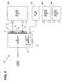
- FIG. 1illustrates a schematic depiction of an RF generator, consistent with the present invention.
- FIG. 2illustrates details of a portion of the embodiment of FIG. 1 , including a pair of RF outputs.
- FIG. 3illustrates a circuit diagram of an RF output of FIG. 2
- FIGS. 4A , 4 B and 4 Cillustrate perspective views of electrode carrier assemblies of three different ablation catheters, consistent with the present invention.
- FIG. 5illustrates a schematic depiction of an RF output portion of an RF generator, including multiplexed outputs, consistent with the present invention.
- FIGS. 6A and 6Billustrate end views of electrode carrier assemblies of two different ablation catheters, consistent with the present invention.
- FIGS. 7A and 7Beach illustrate a circuit equivalent to electrode-tissue interaction employed to demonstrate generation of bipolar and/or monopolar currents, consistent with the present invention.
- FIGS. 8A-Dillustrate a power delivery scheme including four fields configured to deliver only monopolar power, consistent with the present invention.
- FIGS. 9A-Dillustrate a power delivery scheme including four fields configured to deliver a 1:1 ratio of bipolar to monopolar power, consistent with the present invention.
- FIGS. 10A-Dillustrate a power delivery scheme including four fields configured to deliver a 2:1 ratio of bipolar to monopolar power, consistent with the present invention.
- FIGS. 11A-Dillustrate a power delivery scheme including four fields configured to deliver a 4:1 ratio of bipolar to monopolar power, consistent with the present invention.
- FIGS. 12A-Dillustrate a power delivery scheme including four fields configured to deliver only bipolar power, consistent with the present invention.
- FIG. 13illustrates a schematic depiction of a temperature sensor input portion of an RF generator, consistent with the present invention.
- FIG. 14illustrates a circuit diagram of a temperature sensor input portion of an RF generator, consistent with the present invention.
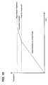
- FIG. 15illustrates a power delivery scheme for an RF generator, consistent with the present invention.
- FIG. 16illustrates a power delivery algorithm for an RF generator, consistent with the present invention.
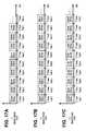
- FIGS. 17A , 17 B and 17 Cillustrates power delivery schemes in which the bipolar to monopolar ratio is set by varying the ratio of bipolar to monopolar fields, consistent with the present invention.
- FIGS. 18A and 18Billustrates power delivery schemes in which the bipolar to monopolar ratio is set by varying the duty cycle percentage within the bipolar and/or monopolar fields, consistent with the present invention.
- FIG. 19illustrates a power delivery scheme in which the bipolar to monopolar ratio is set by varying the length (time) of the bipolar and/or monopolar fields, consistent with the present invention.
- FIG. 20illustrates a schematic of an exemplary embodiment for interfacing RF outputs with an EKG diagnostic device.
- FIG. 21illustrates an exemplary remote control for an RG generator.
- the present inventionprovides catheters for performing targeted tissue ablation in a subject.
- the catheterscomprise a tubular body member having a proximal end and distal end and a lumen extending therebetween.
- the catheteris of the type used for performing intracardiac procedures, typically being introduced from the femoral vein in a patient's leg or from a vessel in the patient's neck.
- the catheteris introducible through a sheath and also has a steerable tip that allows positioning of the distal portion such as when the distal end of the catheter is within a heart chamber.
- the cathetersinclude ablation elements mounted on a carrier assembly.
- the carrier assemblyis attached to a coupler, which in turn is connected to a control shaft that is coaxially disposed and slidingly received within the lumen of the tubular body member.
- the carrier assemblyis deployable by activating one or more controls on a handle of the catheter, such as to engage one or more ablation elements against cardiac tissue, typically atrial wall tissue or other endocardial tissue.
- Electrodes arraysmay be configured in a wide variety of ways and patterns.
- the present inventionprovides devices with electrode arrays that provide electrical energy, such as radiofrequency (RF) energy, in monopolar mode, bipolar mode or combined monopolar-bipolar mode, as well as methods for treating conditions (e.g., atrial fibrillation, supra ventricular tachycardia, atrial tachycardia, ventricular tachycardia, ventricular fibrillation, and the like) with these devices.
- RFradiofrequency
- the normal functioning of the heartrelies on proper electrical impulse generation and transmission.
- proper electrical generation and transmissionare disrupted or are otherwise abnormal.
- the ablation catheters and RF generators of the present inventionmay be employed.
- One current method of treating cardiac arrhythmiasis with catheter ablation therapy. Physicians make use of catheters to gain access into interior regions of the body. Catheters with attached electrode arrays or other ablating devices are used to create lesions that disrupt electrical pathways in cardiac tissue. In the treatment of cardiac arrhythmias, a specific area of cardiac tissue having aberrant conductive pathways, such as atrial rotors, emitting or conducting erratic electrical impulses, is initially localized. A user (e.g., a physician) directs a catheter through a main vein or artery into the interior region of the heart that is to be treated. The ablating element is next placed near the targeted cardiac tissue that is to be ablated.
- a usere.g., a physician
- the physiciandirects energy, provided by a source external to the patient, from one or more ablation elements to ablate the neighboring tissue and form a lesion.
- energyprovided by a source external to the patient
- the goal of catheter ablation therapyis to disrupt the electrical pathways in cardiac tissue to stop the emission of and/or prevent the propagation of erratic electric impulses, thereby curing the focus of the disorder.
- atrial fibrillationcurrently available methods and devices have shown only limited success and/or employ devices that are extremely difficult to use or otherwise impractical.
- the ablation systems of the present inventionallow the generation of lesions of appropriate size and shape to treat conditions involving disorganized electrical conduction (e.g., atrial fibrillation).
- the ablation systems of the present inventionare also practical in terms of ease-of-use and limiting risk to the patient (such as in creating an efficacious lesion while minimizing damage to untargeted tissue), as well as significantly reducing procedure times.
- the present inventionaddresses this need with, for example, carrier assemblies with 3 or 4 carrier arms, carrier assemblies with forward facing electrodes, carrier assemblies with rear-facing electrodes and carrier assemblies configured in a helix or partial helix.
- the carrier assembliesinclude ablation elements such as electrodes which create spiral, radial, or other simple or complex shaped patterns of lesions in the endocardial surface of the atria by delivery of energy to tissue or other means.
- the electrodesmay include projecting fins to improve cooling properties.
- the lesions created by the ablation catheters and RF generators of the present inventionare suitable for inhibiting the propagation of inappropriate electrical impulses in the heart for prevention of reentrant arrhythmias, while minimizing damage to untargeted tissue, such as the esophagus or phrenic nerve of the patient.
- the terms “subject” and “patient”refer to any animal, such as a mammal like livestock, pets, or a human. Specific examples of “subjects” and “patients” include, but are not limited, to individuals requiring medical assistance, and in particular, requiring atrial fibrillation catheter ablation treatment.
- the terms “catheter ablation” or “ablation procedures” or “ablation therapy,” and like terms,refer to what is generally known as tissue destruction procedures.
- Ablationis often used in treating several medical conditions, including abnormal heart rhythms. It can be performed both surgically and non-surgically. Non-surgical ablation is typically performed in a special lab called the electrophysiology (EP) laboratory. During this non-surgical procedure an ablation catheter is inserted into the heart using fluoroscopy for visualization, and then an energy delivery apparatus is used to direct energy to the heart muscle via one or more ablation elements of the ablation catheter. This energy either “disconnects” or “isolates” the pathway of the abnormal rhythm (depending on the type of ablation). It can also be used to disconnect the conductive pathway between the upper chambers (atria) and the lower chambers (ventricles) of the heart. For individuals requiring heart surgery, ablation can be performed during coronary artery bypass or valve surgery.
- the term “ablation element”refers to an energy delivery element, such as an electrode for delivering electrical energy.
- Ablation elementscan be configured to deliver multiple types of energy, such as ultrasound energy and cryogenic energy, either simultaneously or serially.
- Electrodescan be constructed of a conductive plate, wire coil, or other means of conducting electrical energy through contacting tissue.
- monopolar energy delivery modethe energy is conducted from the electrode, through the tissue to a return or ground pad, such as a conductive pad attached to the back of the patient. The high concentration of energy at the electrode site causes localized tissue ablation.
- bipolar energy delivery modethe energy is conducted from a first electrode to one or more separate electrodes, relatively local to the first electrode, through the tissue between the associated electrodes. Bipolar energy delivery results in more precise, shallow lesions while monopolar delivery results in deeper lesions. Both monopolar and bipolar delivery provide advantages, and the combination of their use is one embodiment of this application.
- carrier assemblyrefers to a flexible carrier, on which one or more ablation elements are disposed.
- Carrier assembliesare not limited to any particular size, or shape, and can be configured to be constrained within an appropriately sized lumen.
- carrier armrefers to a wire-like shaft capable of interfacing with electrodes and the coupler.
- a carrier armis not limited to any size or measurement. Examples include, but are not limited to: stainless steel shafts; Nitinol shafts; titanium shafts; polyurethane shafts; nylon shafts; and steel shafts.
- Carrier armscan be entirely flexible, or may include flexible and rigid segments.
- tissuethat has received ablation therapy. Examples include, but are not limited to, scars, scabs, dead tissue, burned tissue and tissue with conductive pathways that have been made highly resistive or disconnected.
- coagulumrefers to a blood mass or clot such as a clot which may be caused by excessive heating in blood.
- the terms “return pad” or “ground pad”interchangeably refer to a surface electrode mounted to the patient's body, typically on the patient's back.
- the return padreceives the RF ablation currents generated during monopolar power delivery.
- the return padis sized (large enough) such that the high temperatures generated remain within a few millimeters of the specific ablation catheter's electrode delivering the monopolar power.
- RF outputrefers to an electrical output produced by the RF generator of the present invention.
- the RF outputis electrically connected to a jack or other electromechanical connection means which allows electrical connection to one or more electrodes of an ablation catheter.
- the RF outputprovides the RF energy to the electrode to ablate tissue with bipolar and/or monopolar energy.
- channelrefers to a pair of RF outputs between which bipolar energy is delivered.
- Each of the RF outputs in a channelmay also deliver monopolar energy (simultaneous and/or sequential to bipolar energy delivery), such as when a return pad is connected.
- targeted tissuerefers to tissue identified by the clinician (and/or one or more algorithms of the system) to be ablated, such as to disconnect an aberrant electrical pathway causing an arrhythmia, or other undesired tissue such as cancer tissue.
- untargeted tissuerefers to tissue which is desired to avoid damage by ablation energy, such as the esophagus or phrenic nerve in an arrhythmia ablation procedure.
- set ablation timerefers to a time period over which ablation energy is delivered to targeted tissue in a relatively continuous manner, to ablate that tissue.
- the set ablation timeis set by the operator and/or automatically set by one or more algorithms of the system of the present invention.
- duty cyclerefers to the proportion of time during which a component, device or system is operated.
- the duty cyclecan be expressed as a ratio or as a percentage.
- a microwave ovenis a good example of a product that uses duty cycle for power control. At, e.g., power level one, the oven will be on for one second, and then off for nine seconds. This cycle repeats until the timer runs out. The oven is on for one out of ten seconds, or 1/10 of the time, and its duty cycle is therefore 1/10 or 10 percent.
- the term “field”refers to a single period of a duty cycle. Each field includes an “on” time in which energy is delivered and an “off” time in which no energy is delivered. In the system of the present invention, a sequential set of fields (e.g. 2, 4, 8) have a customized power delivery scheme which repeats over time.
- power delivery schemerefers to a set of ablation parameters to be delivered during a set ablation time, and used to safely create an effective lesion in targeted tissue.
- Power delivery scheme parametersinclude but are not limited to: type (bipolar and/or monopolar) of energy delivered; voltage delivered; current delivered; frequency of energy delivery; duty cycle parameter such as duty cycle percentage or length of period; field parameter such as configuration of fields or number of fields in set that repeats; and combinations thereof.
- PIDProportional, Integral, Derivative
- Cruise control in a car and a house thermostatare common examples of how PID-based controllers are used to automatically adjust some variable to hold the measurement at the set-point.
- the present inventionprovides structures that embody aspects of the ablation catheter.
- the present inventionalso provides RF generators for providing ablation energy to the ablation catheters.
- the illustrated embodimentsdiscuss these structures and techniques in the context of catheter-based cardiac ablation. These structures, systems, and techniques are well suited for use in the field of cardiac ablation.
- the inventionis applicable for use in other tissue ablation applications such as tumor ablation procedures.
- the various aspects of the inventionhave application in procedures for ablating tissue in the prostrate, brain, gall bladder, uterus, and other regions of the body, such as regions with an accessible wall or flat tissue surface, using systems that are not necessarily catheter-based.
- the target tissueis tumor tissue.
- the multifunctional catheters and RF generators of the present inventionhave advantages over previous prior art devices.
- the accompanying figuresshow various embodiments of the ablation systems of the present invention. The present invention is not limited to these particular configurations.
- Electrodes and array designsmay include multiple electrodes, and in some configurations also include a return or ground pad (a large surface area electrode often attached to the patient's back). At least one pair of electrodes, and often many pairs, may be activated or powered with appropriately-powered potential differences to create RF waves that penetrate and ablate desired tissue. If the powering occurs between a pair of electrodes, it is termed “bipolar”. If the powering occurs between one electrode and the return pad, it is termed “monopolar”. If both bipolar and monopolar power is delivered simultaneously to tissue, it is termed “combo,” “combo mode” or “bipolar/monopolar mode.”
- FIG. 1shows a schematic depiction of an embodiment of the invention.
- System 100includes RF generator (RFG) 10 , which is attached to a power source, to ablation catheter 90 a and also to return pad 80 .
- a source of powersuch as AC line voltage of 120V, 220V, etc of single or multiple phase, or a DC source such as an electrochemical battery, is coupled to ablation catheter 90 a through RF generator (RFG) 10 .
- the power sourcesuch as the electrochemical battery
- RFG 10provides ablation energy to one or more ablation catheters by sending power to one or more independently controlled RF outputs 31 included in RF bank 30 .
- each RF outputallows a unique, programmable power delivery signal to be sent to each electrode of an ablation catheter.
- the independent control of each RF outputfurther allows unique (independent) closed loop power delivery, such as power delivery regulated by tissue temperature information received from one or more temperature sensors integral to the attached ablation catheter and/or from sensors included in a separate device.
- a multiple wire cable 92attaches RF bank 30 to the electrodes of ablation catheter 90 a via electrode connection 91 .
- the electrodesare not shown but may be metal plates with or without projecting fins that connect to electrode connection 91 via individual wires.
- RF bank 30includes twelve separate, electrically-isolated RF outputs, grouped into two outputs per channel (six channels total). Each RF output 31 is configured to provide monopolar, bipolar or a combination of monopolar and bipolar currents simultaneously. The number of RF outputs can vary as required by the design. In one embodiment, four to twelve independent RF outputs are provided, such as when the system of the present invention includes a kit of ablation catheters including at least one catheter with from four to twelve electrodes. In another embodiment, more than 16 independent RF outputs are provided, such as when the system of the present invention includes a kit of ablation catheters including at least one catheter with sixteen electrodes.
- Monopolar deliveryis accomplished by delivering currents that travel from an RF output 41 of bank 40 to an electrically attached electrode of an ablation catheter, through tissue to return pad 80 , and back to RFG through connection 11 to which return pad 80 has been connected.
- Bipolar deliveryis accomplished by delivering current between a first RF output 41 which has been electrically connected to a first electrode of an ablation catheter and a second RF output 41 which has been electrically connected to a second electrode of the ablation catheter, the current traveling through the tissue proximate the first and second electrodes.
- Combo mode energy deliveryis accomplished by combining the monopolar and bipolar currents described immediately hereabove.
- simultaneous monopolar and bipolar currentsare delivered by utilizing a constant voltage source for all pairs of RF outputs (channels). Varying the voltage phase angle between the paired electrodes can be used to adjust the magnitude of power delivered as well as adjust the ratio of monopolar to bipolar power delivery.
- the usere.g. a clinician or clinician's assistant
- a variable voltage sourceis applied to the RF outputs.
- the voltage phase anglemay be fixed (e.g. 0° phase difference for monopolar and 180° phase difference for bipolar). Alternatively, in addition to varying the voltage, the phase angle may be varied.
- the ratio of bipolar to monopolarmay be varied by other means, such as by adjusting the ratio of “cumulative” delivery times of the monopolar versus bipolar (or combo) currents (described in detail in reference to FIGS. 17A-17C , 18 A- 18 B and 19 herebelow).
- five different pre-set energy delivery optionsare provided to the user: monopolar-only, bipolar-only, and 4:1, 2:1 and 1:1 bipolar/monopolar ratios.
- a bipolar-only optionprovides the shallowest depth lesion, followed by 4:1, then 2:1, then 1:1 and then monopolar-only which provides the deepest depth lesion.
- the ability to precisely control lesion depthincreases the safety of the system and increases procedure success rates as target tissue can be ablated near or over important structures.
- currentsare delivered in either monopolar mode or combo mode (only). The embodiment which avoids bipolar-only, has been shown to provide numerous benefits including reduction of electrical noise generated by switching off the return pad circuit (e.g. to create bipolar-only mode).
- RFG 10includes multiple independent PID control loops that utilize measured tissue temperature information to regulate (i.e. provide closed loop) energy delivered to an ablation catheter's electrodes.
- a multiple wire cable 94attaches temperature sensor input bank 40 to the thermocouples of ablation catheter 90 a via thermocouple connection 93 .
- the thermocouplesare not shown but may be integral to the electrodes of ablation catheter 90 a and electrically connected to thermocouple connection 93 via one or more wires.
- multiple wire cable 92 and multiple wire cable 94are a single conduit.
- the PID control loops of RFG 10receive the temperature information via temperature sensor inputs 41 of bank 40 .
- temperature sensor input bank 40includes twelve separate, electrically-isolated temperature sensor inputs.
- Each temperature input 41is configured to receive temperature information such as from a sensor such as a thermocouple.
- the number of temperature inputscan vary as required by the design. In one embodiment, four to twelve independent inputs are provided, such as when the system of the present invention includes a kit of ablation catheters including at least one catheter with from four to twelve thermocouples. In another embodiment, more than 16 independent temperature inputs are provided, such as when the system of the present invention includes a kit of ablation catheters including at least one catheter with at least sixteen thermocouples.
- Ablation target temperaturesare user-selectable and automatically achieved and maintained throughout lesion creation, regardless of blood flow conditions and/or electrode contact scenarios. Temperature target information is entered via user interface 20 of RFG 10 .
- User interface 20may include a touch screen display, a membrane keypad or other user input components integral to or separate from a housing of RFG 10 (refer to FIG. 21 for a separate remote control configuration).
- User interface 20also includes user output components such as text and graphic display screens, indicator lights and other user output components integral to or separate from a housing of RFG 10 .
- User interface 20is configured to allow an operator to input system parameter and output configuration information including but not limited to: electrode selection; power delivery settings, targets and other power delivery parameters; and other information.
- User interface 20is further configured to provide information to the operator, such as visual and audible information including but not limited to: electrode selection, power delivery parameters and other information.
- Automatic temperature-controlled lesion creationprovides safety and consistency in lesion formation. Typical target temperature values made available to the operator range from 50 to 70° C.
- duty cycle power controlin order to regulate power across a number of separate RF outputs 31 that utilize phase angle differences to generate bipolar currents, greatly simplifies the control and regulation of power.
- Utilizing duty cycle power controlalso provides the ability to deliver high peak powers while providing electrode cooling time during the off-portion of the duty cycle.
- Duty cycle controlis configured such that the period (“on” time plus “off” time) is much less than the thermal time constant of the tissue, such that the tissue acts as an “integrator”, continuously accumulating the heat energy while the electrodes of the ablation catheter cool during the off period.
- the period of each duty cycleis approximately 17 msec, and the thermal time constant is much longer than 17 msec.
- Duty cycle periods of approximately 17 msecare applicable to the system of the present invention. Duty cycle periods that are too long result in inadequate ablation of targeted tissue. Duty cycle periods that are too short result in inadequate cooling which may cause char or other blood clots, or damage untargeted tissue. In alternative embodiment, the duty cycle periods may range from 10 msec to 500 msec, and may be adjustable by the operator of the RFG via, e.g., the user interface. Duty cycle energy delivery provides increased efficiency, effectiveness and safety during lesion creation at reduced RMS power levels.
- amplitude controlmay replace or work in conjunction with duty cycle control.
- a fixed duty cyclee.g. a 10% duty cycle
- the voltagemay be regulated (to an amplifier of each RF output 31 ), such as voltage regulated by the temperature PID loops described above to similarly achieve a target tissue temperature in a precise manner.
- the duty cycle percentagecan be increased (e.g. in small steps) until equilibrium is achieved (i.e. the varied voltage, varied duty cycle embodiment mentioned above).
- the duty cycle percentage chosenprovides a power limit (as well as bipolar to monopolar power ratios), and the temperature achieved is regulated by varying RF amplitude (voltage) delivered to RF outputs 31 , in monopolar, bipolar, or combo mode energy delivery.
- the temperature ratio between the various electrodescan be controlled by adjusting each RF output's duty cycle, such as to balance the temperature across the lesion.
- this varied voltage control configurationinvolves the addition of 12 separate variable power supply circuits on RF circuit boards of RFG 10 , such as to work with ablation catheters including up to 12 electrodes.
- the duty cycle percentageis typically set in the range of 5% to 25% depending upon the (tissue) load resistance and power required for adequate ablation.
- This voltage-varied configurationis an alternative method of power control that can give the same or similar clinical effects to the duty cycle power control described above.
- system 100further includes ablation catheter 90 b and ablation catheter 90 c , each of which is configured to attach to RF output bank 30 and temperature sensor input bank 40 for energy delivery and temperature feedback similar to that described above in reference to ablation catheter 90 a .
- Ablation catheters 90 a , 90 b and 90 cmay be of the construction described herebelow in reference to FIGS. 4A , 4 B and 4 C respectively.
- Alternative or additional ablation cathetersmay be included in the system of the present invention.
- FIG. 2illustrates two parallel circuits which produce a first RF output 31 a and a second RF output 31 b , such as a pair of RF outputs (a channel)—used to deliver bipolar energy to a pre-determined pair of electrodes on an ablation catheter.
- the parallel circuits for RF output 31 a and RF output 31 binclude half-bridge circuits 32 a and 32 b , series resonant circuits 33 a and 33 b , and output transformers 34 a and 34 b , respectively.
- Half-bridge circuits 32 a and 32 beach receive a drive signal from signal generator 35 , such as a programmable logic device (PLD).
- PLDprogrammable logic device
- Half bridge circuits 32 a and 32 beach produce a square wave, e.g. a 24-volt peak-to-peak square wave.
- Series resonant circuits 33 a and 33 beach couple the high power square wave to output transformers 34 a and 34 b respectively.
- Output transformers 34 a and 34 beach is an isolation transformer configured to provide both patient electrical isolation and the voltage step-up required to ablate tissue.
- the ablation electrodesare at patient potential, and 5000-6000 volts isolation is provided between the electrodes and earth ground. Since the input is at chassis ground, output transformers 34 a and 34 b each is configured to provide 5000-6000 volts isolation between its primary and secondary coils.
- An additional advantage of this isolation circuitryis that power can be measured without the need to isolate the measuring devices. A portion of the applicable circuitry is shown in FIG. 3 .
- Series resonant circuits 33 a and 33 beach convert the square ware received from half bridge circuits 32 a and 32 b respectively, to a sine wave. These conversions are accomplished by maximizing energy coupling at the fundamental frequency chosen, e.g., at 470 kHz.
- This power output configurationis over 95% efficient in converting the 24 VDC input power to RF energy, as the output transformer has an efficiency close to 100%.
- half-bridge circuit 32 a and 32 b , series resonant circuit 33 a and 33 b and output transformer 34 a and 34 bare configured to convert signal generator's 45 470 kHz logic level signal to two 100 VAC sine waves, each capable of delivering 100 watts.
- P inputpower inputted
- P outputoutputted power
- a current-sensing resistoris employed (not shown, but having a precise, known resistance) so inputted current (I in ) can be determined by the system. Since inputted voltage (V in ) is also known, as the power supply precisely regulates this, the system can determine P in and thus P output .
- the systememploys a frequency of 470 kHz (or approximately 470 kHz, noting that 500 kHz is not used as it may be reserved for a public emergency band.)
- the 470 kHzis generated by a PLD, signal generator 35 .
- an oscillatorprovides (starts with) a higher frequency, which is then divided down to 470 kHz.
- the 470 kHz waveformmay be generated in numerous configurations, such as with 0° phase or any other phase, such as a phase determined in 250 steps or divisions.
- the signal for the PLDis a 5-volt digital signal with the phase information “built-in”.
- Signal generator 35also generates the opposite polarity signal which may also be used to drive one or more field effect transistors (FETs) integral to half bridge circuit 32 a and 32 b .
- FETsfield effect transistors
- Signal generator 35provides a synchronization pulse, not shown but connected to the signal generators of subsequent pairs of RF outputs also not shown; such that all the signal generators of the RFG are in synchrony (i.e. signal generator 35 is the “master”).
- an RF circuit boardincludes two circuits of FIG. 2 , i.e. two signal generator 35 's, four half bridge circuits 32 's, four series resonant circuits 33 's and four output transformers 34 's, producing four RF outputs (or two channels).
- 2 RF boardswould provide 8 RF outputs and 3 RF boards would provide 12 RF outputs.
- Signal generator 35is under microprocessor control.
- the microprocessorcan set the duty cycle from all “off” to all “on” in at least 16 steps, and possibly 256 steps.
- the microprocessorcan adjust the phase of the RF output can be set from 0° to 180° in at least 4 steps, and possibly 16 steps. This adjustability allows the energy to flow to pairs of electrodes in the following ways: all monopolar from the electrodes to the return pad; all bipolar between the electrodes; and a combination of bipolar and monopolar with the ratio set by the phase difference between the electrodes.
- Transformer T 1is an isolation transformer.
- Resistor R 2e.g., approximately 2000 ohms, provides a static load across the RF amplifier circuitry and improves the stability of the signal during light load conditions.
- Carrier assembly 210 aincludes a single carrier arm 211 a with multiple electrodes 220 a (e.g. 10 electrodes) mounted along its length.
- Each electrodeis constructed of a conductive material, such as platinum, and typically has a mass between 20 and 50 milligrams, or between 30 and 40 milligrams.
- Each electrode 220 amay include a thermocouple, not shown, but integral to electrode 220 a and proximate the tissue contacting surface of electrode 220 a .
- thermocouplesmay be small mass thermocouples, typically less than 200 micrograms or less than 100 micrograms, such as to provide fast and accurate tissue/electrode interface temperatures.
- the thermocouples integral to electrodes 220 aare made of 38 gauge wire and have a mass between 48 and 88 micrograms, typically 68 micrograms.
- Carrier assembly 210 acan be adjusted to transition between a near-linear geometry to the near-helical geometry shown in FIG. 4A .
- Carrier assembly 210 amay be configured for making contact with a pulmonary vein ostium of a patient.
- Carrier assembly 210 bincludes multiple electrodes 220 b (e.g. 8 electrodes) mounted to four carrier arms 211 b arranged in an umbrella configuration.
- the tissue contacting portion of electrodes 220 bface away from the proximal end of the ablation catheter such that pushing forward carrier assembly 210 b advances the tissue contacting portion of electrodes 220 b into tissue.
- Each electrodeis constructed of a conductive material, such as platinum, and typically has a mass between 17 and 37 milligrams, such as approximately 27 milligrams.
- Each electrode 220 bmay include a thermocouple, not shown, but integral to electrode 220 b and proximate the tissue contacting surface of electrode 220 b .
- the thermocouplesmay be small mass thermocouples, typically less than 200 micrograms or less than 100 micrograms, such as to provide fast and accurate tissue/electrode interface temperatures.
- the thermocouples integral to electrodes 220 bare made of 40 gauge wire and have a mass between 22 and 62 micrograms, typically 42 micrograms.
- Each electrode 220 bmay include a projecting fin as shown, configured to provide a heat sink into circulating blood.
- Carrier assembly 210 bcan be adjusted to transition between a near-linear geometry to the umbrella geometry shown in FIG. 4B .
- Carrier assembly 210 bmay be configured for making contact with the far wall of the left or right atrium of the heart of a patient.
- Carrier assembly 210 cincludes multiple electrodes 220 c (e.g. 12 electrodes) mounted to three carrier arms 211 c arranged in an umbrella configuration.
- the tissue contacting portion of electrodes 220 cface toward the proximal end of the ablation catheter such that pulling carrier assembly 210 c advances the tissue contacting portion of electrodes 220 c into tissue.
- Each electrodeis constructed of a conductive material, such as platinum, and typically has a mass between 17 and 37 milligrams, such as approximately 27 milligrams.
- Each electrode 220 cmay include a thermocouple, not shown, but integral to electrode 220 c and proximate the tissue contacting surface of electrode 220 c .
- the thermocouplesmay be small mass thermocouples, typically less than 200 micrograms or less than 100 micrograms, such as to provide fast and accurate tissue/electrode interface temperatures.
- the thermocouples integral to electrodes 220 care made of 38 gauge wire and have a mass between 48 and 88 micrograms, typically 68 micrograms.
- Each electrode 220 cmay include a projecting fin as shown, facing away from the proximal end of the ablation catheter and configured to provide a heat sink into circulating blood.
- Carrier assembly 210 ccan be adjusted to transition between a near-linear geometry to the umbrella geometry shown in FIG. 4C .
- Carrier assembly 210 cmay be configured for making contact with the septum of the left atrium of the heart of a patient.
- the ablation catheters of FIGS. 4A , 4 B and 4 Care each ablation catheters configured to receive energy from the RF generator of the present invention. Additional and/or alternative catheters may also be configured to receive energy from the RF generator of the present invention.
- Each of the ablation catheters of FIGS. 4 a , 4 B and 4 Cmay include a thermocouple within each electrode. Alternatively or additionally, one or more carrier arms include a thermocouple along its length, such as midway between two electrodes.
- thermocouplesPlacement of the thermocouple in the electrode is such that during ablation, thermocouples are located directly over the target tissue at a distance separated by the electrode wall thickness only (such as a wall thickness of 0.006′′ or alternatively a wall thickness ranging from 0.004′′ to 0.010′′).
- the combination of thermocouple location, size and mounting methodsprovides fast and accurate tissue/electrode interface temperatures.
- Type T thermocouples(copper/constantan) may be employed as the temperature accuracy curve for type T is essentially linear within the temperature range used by the ablation system, i.e., body temperature through 80° C.
- FIG. 5another configuration of the present invention is illustrated in which the RF Generator's independent RF outputs can be selectively connected to the electrodes of one or more ablation catheters.
- Multiple outputs transformerssuch as output transformer 34 a , each of which produces an independent RF output, such as RF output 31 a , are connected to multiplexer 36 .
- Multiplexer 36includes circuitry to selectively connect each RF output to one of a bank of connections, each of which is electrically connected to one or more electrodes of an ablation catheter. Via a user interface of the RF generator, not shown, the operator can select which RF outputs are connected to which electrodes, such as to deliver bipolar or combo energy to any pair of electrodes.
- carrier assembly 210 aincludes four carrier arms 211 a on which eight electrodes are fixedly mounted.
- carrier assembly 210 bincludes three carrier arms 211 b on which twelve electrodes are fixedly mounted.
- any pairs of electrodesmay receive bipolar energy such as electrode pair “1-2” or “2-4” of carrier assembly 210 a of FIG. 6A , or electrode pair “3-4” or “4-12” of carrier assembly 210 b of FIG. 6B .
- All combinations of energy deliveryare enabled by the independent control of each RF output combined with the electrode selectivity provided by multiplexer 36 and associated circuitry of FIG. 5 .
- the energy deliveredcan be customized based on individual patient requirements.
- energy deliverymay start on the outermost electrodes (e.g. 1 , 3 , 6 and 8 of FIGS. 6A and 1 , 5 and 9 of FIG. 6B ), and drive power to the center.
- the centermost electrodese.g. 2 , 4 , 5 and 7 of FIGS. 6A and 4 , 8 and 12 of FIG. 6B ) receive energy simultaneously.
- the linearly aligned electrodes of FIG. 6A or FIG. 6Bdeliver energy to produce a circular lesion.
- a first electrode mounted to a first carrier armtransmits bipolar energy to a second electrode mounted to a second carrier arm.
- FIGS. 7A and 7Btwo schematic representations of multiple electrode assemblies and a return pad each in contact with patient tissue are shown.
- FIG. 7Aif four separate RF outputs of the same voltage and phase were connected to Electrode 1 , Electrode 2 , Electrode 3 , and Electrode 4 , and the return pad connected to RF Generator ground, there would be current flow through tissue portions T 1 , T 2 , T 3 and T 4 . There would be zero current flow through tissue portions T 5 , T 6 and T 7 .
- four separate RF outputs of all different voltageswere connected to Electrode 1 , Electrode 2 , Electrode 3 , and Electrode 4 and the return pad was disconnected (i.e.
- the phase difference between Electrode 5 and Electrode 6would cause a potential difference of 80 volts.
- the generation of the combined bipolar and monopolar currentsis achieved by varying the phase, as described above.
- the combined bipolar and monopolar currentsare determined by time-division multiplexing and/or by alternating monopolar and bipolar fields, as will be described in detail in reference to subsequent figures.
- repeating duty cycle fieldsare employed, each field having a similar period (duration) and each field including an “on” portion and an “off” portion.
- a possible field periodis approximately 17 msec.
- RMStypically 100 volts RMS
- the output of the channelis disconnected from the load.
- a sequence of four specific duty cycle fields that repeatare provided.
- a first fieldincludes monopolar energy delivery only followed by an off period; the second field includes combined monopolar and bipolar delivery (combo) followed by an off period; the third field includes monopolar energy delivery only followed by an off period; and the fourth field includes monopolar and bipolar delivery (combo), with opposite phase from that of field 2 , followed by an off period.
- the ratio between bipolar and monopolar energy deliverycan be varied from 4-to-1 to all-monopolar.
- an all-bipolar modecan be produced.
- the ablation signal delivered to each electrode pair from two associated RF outputs (channel)includes four fields (e.g. each of 17 ms period), the four fields repeating until ablation energy delivery is terminated. Each field is divided into an “on” time and an “off” time. This duty cycle ratio controls the amount of power delivered during each field by that RF output pair (channel). In one embodiment, during the “on” time, 100 volts RMS (at 470 kHz) is delivered to the load. During the “off” time, the output is floating, thus zero power is delivered. For example, a duty cycle of 10% would cause a power of 10 watts RMS to be delivered into a 100 ohm load during the duty cycle period (e.g.
- each RF output pairmay deliver RF power in monopolar, bipolar or combo energy delivery.
- Each fieldmay include “on” time ratios (monopolar, bipolar or combo) from 0% to 100% of the duty cycle period, typically 17 msec.
- each energy deliveryincludes at least monopolar energy delivered, avoiding the need to disconnect the return pad. Continuous connection of the return pad avoids generation of electrical noise, and allows the inclusion of safety detection circuitry which requires connection of the return pad.
- FIG. 8a repeating sequence of four fields configured to deliver monopolar power (only) to an RF output pair, or channel, is illustrated.
- the RF output pair receiving energyis connected to a pair of electrodes on an attached ablation catheter.
- RMSat 470 kHz
- the outputis floating, thus zero power is delivered.
- the return padis connected during all four fields, maintained at 0 volts and receives the monopolar currents from each electrode delivering monopolar energy.
- all four fieldshave a 17 msec duty cycle period.
- the four fieldsrepeat until the set ablation time is reached, or an alarm or alert condition is identified. All four fields have 0° phase shift between the two RF outputs (no bipolar energy delivery) causing monopolar energy to be delivered to the tissue in contact with the electrode pair during each of the four fields.
- a repeating sequence of four fieldsconfigured to deliver a 1:1 ratio of bipolar to monopolar power to an RF output pair, or channel, is illustrated.
- the RF output pair receiving energyis connected to a pair of electrodes on an attached ablation catheter.
- RMSat 470 kHz
- the outputis floating, thus zero power is delivered.
- the return padis connected and maintained at 0 volts during all four fields, and receives the monopolar currents from each electrode delivering monopolar energy.
- all four fieldshave a 17 msec duty cycle period.
- Field 1 and Field 3have 0° phase shift between the two RF outputs (no bipolar energy delivery) causing monopolar energy to be delivered to the tissue in contact with the electrode pair during the “on” time of Field 1 and Field 3 .
- Field 2 and Field 4have a 90° phase shift between the two RF outputs such that bipolar energy is delivered between the electrodes connected to the two RF outputs. Since the return pad is connected (as it is in Fields 1 and 3 ), monopolar energy is also delivered in Fields 2 and 4 (combo mode). As has been described above, the 90° phase shift causes twice the amount of bipolar energy as monopolar energy to be delivered, during that field where both are delivered.
- a repeating sequence of four fieldsconfigured to deliver a 2:1 ratio of bipolar to monopolar power to an RF output pair, or channel, is illustrated.
- the RF output pair receiving energyis connected to a pair of electrodes on an attached ablation catheter.
- RMSat 470 kHz
- the outputis floating, thus zero power is delivered.
- the return padis connected and maintained at 0 volts during all four fields, and receives the monopolar currents from each electrode delivering monopolar energy.
- all four fieldshave a 17 msec duty cycle period.
- Field 1 and Field 3have 0° phase shift between the two RF outputs (no bipolar energy delivery) causing monopolar energy to be delivered to the tissue in contact with the electrode pair during the “on” time of Field 1 and Field 3 .
- Field 2 and Field 4have a 180° phase shift between the two RF outputs such that bipolar energy is delivered between the electrodes connected to the two RF outputs. Since the return pad is connected (as it is in Fields 1 and 3 ), monopolar energy is also delivered in Fields 2 and 4 (combo mode). As has been described above, the 180° phase shift causes four times the amount of bipolar energy as monopolar energy to be delivered, during that field where both are delivered.
- a repeating sequence of four fieldsconfigured to deliver a 4:1 ratio of bipolar to monopolar power to an RF output pair, or channel, is illustrated.
- the RF output pair receiving energyis connected to a pair of electrodes on an attached ablation catheter.
- RMSat 470 kHz
- the outputis floating, thus zero power is delivered.
- the return padis connected and maintained at 0 volts during all four fields, and receives the monopolar currents from each electrode delivering monopolar energy.
- all four fieldshave a 17 msec duty cycle period.
- All fieldsrepeat until the set ablation time is reached, or an alarm or alert condition is identified.
- All fields ( 1 - 4 )have a 180° phase shift between the two RF outputs such that bipolar energy is delivered between the electrodes connected to the two RF outputs. Since the return pad is connected, monopolar energy is also delivered in all fields (combo mode). As has been described above, the 180° phase shift causes four times the amount of bipolar energy as monopolar energy to be delivered, during that field where both are delivered. Since all the fields are configured the same, the 4:1 ratio is delivered.
- FIG. 12a repeating sequence of four fields configured to deliver only bipolar power to an RF output pair, or channel, is illustrated.
- the RF output pair receiving energyis connected to a pair of electrodes on an attached ablation catheter.
- RMSat 470 kHz
- the outputis floating, thus zero power is delivered.
- the return padis disconnected, preventing monopolar energy delivery.
- all four fieldshave a 17 msec duty cycle period. The four fields repeat until the set ablation time is reached, or an alarm or alert condition is identified.
- All fields ( 1 - 4 )have a 180° phase shift between the two RF outputs such that bipolar energy is delivered between the electrodes connected to the two RF outputs. Since the return pad is disconnected, no monopolar energy is delivered in any field.
- the RF generatorcan be operated in bipolar-only mode with the return pad can be left connected by adjusting the phase angles such that ensure that all current flows only between the ablation electrodes and none flows to the return pad.
- all fieldsinclude monopolar power delivery such that the return pad is never switched off.
- the power delivery schemes illustrated in FIGS. 9-12utilize a phase shift adjustment between two RF outputs to control the ratio of bipolar to monopolar power delivery.
- the system of the present inventionis configured to independently provide similar or dissimilar fields of energy delivery to other provided channels, such as RF output pairs connected to 4, 8, 12, 16 or more electrodes of an ablation catheter. Additional variables may be controlled to modify the bipolar-monopolar ratio, total power delivered, or other output parameter, such variables including but not limited to: duty cycle percentage; duty cycle period; applied voltage; frequency of applied voltage; shape of applied voltage such as sinusoidal, triangle wave or square wave; connection to the return pad; voltage applied to return pad; and combinations thereof.
- the system of the present inventionallows independent phase control of each RF output (e.g. up to 16 outputs or more), providing more sophisticated power delivery as compared to a previously developed system in which every other channel was driven at the same phase and each RF output drove two electrodes.
- Each of the RF outputscan be driven up to a maximum power, and ablation energy can be sent to each RF output simultaneously or sequentially.
- the ability to control the phase of each electrode relative to the other electrodesenables the system to generate bipolar currents as well as monopolar, as well as various combinations of these.
- each RF channelmay utilize independent PID loops which process temperature information (e.g. temperature information received from a thermocouple mounted in each electrode) to modify the power delivery to that pair of RF outputs.
- temperature informatione.g. temperature information received from a thermocouple mounted in each electrode
- PID loopsprovide more accurate temperature-driven energy delivery than previously developed systems.
- One previously developed systemdelivered power to 12 electrodes based on temperature feedback from three zones. The electrodes were regulated to the highest temperature in the zone, which resulted in some of the electrodes ablating inefficiently (e.g. not enough power delivered).
- thermocouple amplifiers43 a , 43 b , 43 c , etc, which are configured to electrically connect to up to twelve thermocouples of one or more ablation catheters of the present invention.
- the thermocouplesmay be small mass thermocouples, typically less than 200 micrograms or less than 100 micrograms, such as to provide fast and accurate tissue/electrode interface temperatures.
- the twelve thermocouple amplifiers 43 a , 43 b , 43 c , etcare electrically connected to a twelve channel analog to digital (A/D) converter 42 .
- A/D converter 42is electrically connected to microprocessor module 15 .
- An RS-232 module 16is electrically connected to microprocessor module 15 .
- Fast and accurate temperature acquisitionis important in delivering the proper amount of RF energy (i.e. closed-loop control). Too much (high) energy delivery can cause coagulum and/or damage adjacent tissues and structures such as the phrenic nerve or the esophagus of the patient. Too little energy delivery can result in poor lesion creation and low therapeutic success rates.
- the system of the present inventionprovides enough RF energy to create a cardiac electrical conduction block without affecting adjacent tissues or structures.
- the thermocouple massis kept small and one or more electrodes are welded directly to the inside diameter of each of the electrodes of each ablation catheter.
- thermocouplesPlacement of the thermocouple in the electrode is such that during ablation, thermocouples are located directly over the target tissue at a distance separated by the electrode wall thickness only (such as a wall thickness of 0.006′′ or alternatively a wall thickness ranging from 0.004′′ to 0.010′′).
- the combination of thermocouple location, size and mounting methodsprovides fast and accurate tissue/electrode interface temperatures.
- Type T thermocouples(copper/constantan) may be employed as the temperature accuracy curve for type T is essentially linear within the temperature range used by the ablation system, i.e., body temperature through 800 C.
- thermocouples located on the ablation electrodesare at patient potential. 5000 volts of isolation is needed between the thermocouples and earth ground in order to meet patient safety regulations (e.g. IEC 601-2).
- the twelve temperature modulesare read by microprocessor module 15 which is powered by a dc-to-dc converter with the proper voltage isolation.
- An RS232 serial data stringis isolated with an opto-isolator. Since the RF power output is duty cycle-controlled, the temperature readings can be synchronized to the “off” period of each field. The synchronizing pulse is also supplied through an opto-isolator.
- thermocouple amplifier circuita schematic of a thermocouple amplifier circuit is shown.
- Each temperature modulemakes use of a true instrumentation amplifier with a precision DC gain of 100 and several poles of RC low pass filtering configured to attenuate the 470 kHz ablation voltage.
- a high-impedance DC bias voltageprovides an indication of when the (very low-resistance) thermocouple is not present.
- FIG. 15one embodiment of energy delivery is illustrated in which dual, sequentially implemented algorithms are employed to control power delivered.
- This method of energy deliverycan be applied independently to each RF output, or each RF channel (pair of RF outputs).
- a user-programmed target temperaturee.g. greater than 5° C. from a target ablation temperature
- energy deliverymay be generated at a fixed level of power, irrespective of temperature sensed by the thermocouples or other temperature sensors (first algorithm).
- P max16 watts
- the systemchanges from fixed (e.g. maximum) power level delivery to energy delivery controlled to temperature (second algorithm where power delivery is regulated by a temperature control loop).
- the systemchanges the duty cycle (“on” time/“off” time ratio) to allow the tissue temperature to controllably progress to the desired target temperature, such as to minimize or prevent overshoot.
- the threshold temperature at which the second algorithm is implementedis also set by the user through, e.g., the user interface.
- a threshold temperatureis also set by the user, instead of a fixed amount such as the 5° C. mentioned above.
- the duty cycle (field) periodis approximately 16-17 msec, such that if 10 watts RMS power is to be delivered for a specific field (entire length) and 100 watts RMS is delivered during the “on” period, the “on” period duration would be set to 1.7 msec and the “off” period duration would be set to 15.3 msec.
- a typical duty cyclemay be about 10%, and a typical voltage applied may be about 100 volts RMS. If the nominal load (impedance of the tissue) is about 100 ohms, this 10% duty cycle would yield 100 watts RMS for the 17 msec period.
- a target temperaturebetween 50° C.-70° C. (e.g., 60° C.) may be set, and the system may deliver energy to heat and ablate as described in reference to FIG. 15 .
- FIG. 16a flow chart of another power control algorithm is illustrated.
- This method of energy deliverycan be applied independently to each RF output, or each RF channel (pair of RF outputs).
- the control methoduses a main control loop and a secondary control loop.
- the main loopcontrols the duty cycle and compares the actual power to a power goal.
- the proportional difference between the goal and the actual poweris added to an integration register.
- the difference between the last power delivered and the present power (the derivative)is subtracted from the integration register.
- the new value in the integration registersets the duty cycle value.
- the secondary control loopcontrols the power goal and compares the actual temperature (measured) to a temperature goal.
- the proportional difference between the goal and the actual temperatureis added to an integration register.
- the difference between the last temperature measured and the present temperature (the derivative)is subtracted from the integration register.
- the value in the integration registersets the power goal value. If the power goal value is greater than the power limit, the power goal is set to equal the power limit.
- the algorithm of FIG. 16provides a safe and efficient way of delivering power to create a lesion, and is particularly effective at limiting overshoot of achieved temperature (above the target temperature).
- an algorithmapplies a set of power limits specific to the bipolar-monopolar ratio used. For one or more ablation catheters of the present invention, this set of power limits is as listed in Table 1 below:
- the bipolar to monopolar energy delivery ratiois varied by adjusting the number (ratio) of monopolar to bipolar fields.
- Held constantare the duty cycle (“on” time and “off” time lengths), the field length (17 msec) and the bipolar delivery phase angle.
- the phase angleis set to 90° such that bipolar energy is twice monopolar energy delivery at the same applied voltage, as has been described above.
- a 1:1 ratio of bipolar to monopolar energy deliveryis achieved with a 1:2 ratio of bipolar to monopolar fields (e.g. a set of two monopolar fields followed by one bipolar field, which repeat).
- a 2:1 ratio of bipolar to monopolar energy deliveryis achieved with a 1:1 ratio of bipolar to monopolar fields (e.g. a set of one monopolar field followed by one bipolar field, which repeat).
- a 4:1 ratio of bipolar to monopolar energy deliveryis achieved with a 2:1 ratio of bipolar to monopolar fields (e.g. a set of one monopolar field followed by two bipolar fields, which repeat).
- the bipolar to monopolar ratiois further adjusted by varying one or more of duty cycle, field length and phase angle.
- one or more bipolar fieldsare replaced with combo fields.
- FIGS. 18A 18 Banother algorithm for setting the ratio of bipolar to monopolar energy delivery is illustrated.
- the bipolar to monopolar energy delivery ratiois varied by adjusting duty cycle (“on” time and “off” time lengths). Held constant are the ratio of bipolar to monopolar fields (set to 1:1), the field length (17 msec) and the bipolar delivery phase angle. In this embodiment, the phase angle is also set to 90° such that bipolar energy is twice monopolar energy delivery at the same applied voltage, as has been described above.
- a 2:1 ratio of bipolar to monopolar energy deliveryis achieved with a 1:1 ratio of bipolar to monopolar “on” times.
- the duty cycleis set to 50%, or 8.5 msec of the 17 msec period.
- a 4:1 ratio of bipolar to monopolar energy deliveryis achieved with a 2:1 ratio of bipolar to monopolar “on” times.
- the bipolar to monopolar ratiois further adjusted by varying one or more of the ratio of bipolar to monopolar fields, field length and phase angle.
- one or more bipolar fieldsare replaced with combo fields.
- the bipolar to monopolar energy delivery ratiois varied by adjusting field length.
- Held constantare the ratio of bipolar to monopolar fields (set to 1:1), the duty cycle (within the fields—e.g. 10%) and the bipolar delivery phase angle.
- the phase angleis also set to 90° such that bipolar energy is twice monopolar energy delivery at the same applied voltage, as has been described above.
- a 4:1 ratio of bipolar to monopolar energy deliveryis achieved with a 2:1 ratio of bipolar to monopolar field lengths (e.g. 34 msec to 17 msec respectively).
- the bipolar to monopolar ratiois further adjusted by varying one or more of the ratio of bipolar to monopolar fields, field length and phase angle.
- one or more bipolar fieldsare replaced with combo fields.
- the applied voltageis also held constant. In alternative embodiments, the voltage is varied to modify the ratio of bipolar to monopolar power delivered. In the embodiments of FIGS. 17A-C , 18 A-B and 19 , some fields include the delivery of bipolar energy. In alternative embodiments, these bipolar energy delivery fields are replaced with combo energy delivery, and the associated variables mathematically adjusted to achieve the desired bipolar to monopolar ratio.
- FIG. 20a schematic of an embodiment for interfacing RF outputs with an EKG diagnostic device is illustrated. It is important that the RF energy delivered is “isolated” from an EKG diagnostic device or module (such as a separate EKG monitor or an EKG monitor integrated into the RF generator of the present invention).
- a resistorsuch as a 10 Kohm resistor in series with the output, can be used to attenuate the RF power yet let the mapping information pass through. The issue with such a configuration is the mapping information is also attenuated dramatically.
- a 1000 milliHenry inductor L 1is placed between the RF output 31 a and the input to the EKG module EKG 1 .
- the inductorprovides sufficient attenuation of the high frequency RF signal (e.g. 3300 ohms of impedance with RF delivered at 470 kHz as has been described above), yet very low impedance in the lower frequency spectrum representing EKG information.
- a second inductor L 2is placed between second RF output 31 b and a second input to the EKG module EKG 2 .
- a capacitor C 1is placed between EKG 1 and EKG 2 , completing a low-pass filter which reduces the RF voltage that is “exposed” to an attached EKG diagnostic device.
- Inductorscan be placed between each RF output (i.e. connected to each electrode of an ablation catheter) and an associated EKG diagnostic device input.
- Remote control 500is configured to send commands to an RFG of the present invention, via information input into user interface 520 by an operator of the system.
- User interface 520is configured to allow an operator to input system parameter and output configuration information including but not limited to: electrode selection; power delivery settings, targets and other power delivery parameters; and other information.
- User interface 520may be further configured to provide information to the operator, such as visual and audible information including but not limited to: electrode selection, power delivery parameters and other information.
- remote control 500provides full control of the RFG of the present invention, such that no other user interface is required to perform any and all functions of the RFG.
- remote control 500provides partial control of the RFG.
- User interface 520may replace a user interface integral to an RFG, or work in combination with it.
- user interface 520is the master control, overriding conflicting commands from a user interface of the RFG.
- the user interface of the RFGis the master control.
- User interface 520includes a bank of switches, such as a membrane keypad, and/or other user input components, to enter commands to be received by the RFG.
- User interface 520further includes user output components such as indicator lights, displays such as LCD displays, and other means of presenting information to an operator of the RFG.
- user interface 520includes a touch screen display configured to provide information to the user and receive commands from the user.
- Remote control 500includes a housing 501 , such as a plastic housing which surrounds one or more electronic modules and includes user interface 520 on its top, outer surface.
- a bundle of wiresconnect remote control 500 to the RFG of the present invention, such as via a ten pin receptacle integral to the housing of the RFG.
- remote control 500includes a wireless transceiver, not shown but possibly configured to send and receive wireless transfer of information to and from the RFG, such as via a handshaking protocol which assures accuracy of information transfer.
- Remote control 500may be provided sterilized and/or may be covered with a disposable sterile bag, not shown, but configured to surround remote control 500 and at least a portion of any wires attached to remote control 500 .
- the sterile assemblymay be brought into the sterile field of a patient undergoing a sterile procedure, such as a cardiac ablation procedure to treat atrial fibrillation, or a tumor ablation procedure.
- the systems of the present inventionmay include one or more power limits which can be integrated into software and/or hardware of the RFG.
- the systemmay employ different power limits for different ablation catheters.
- the systemmay employ different power limits for different bipolar-monopolar ratios.
- the systemincludes power limits from Table 1 above.
- different power limitsor sets of power limits as shown in the above table) are used for different ablation catheters.
- power limits of 20-30 Watts RMSmay be used by one or more algorithms for one or more ablation catheters of the present invention.
- ablation catheters with larger electrodesmay correlate to a higher power limit than an ablation catheter with smaller electrodes.
- the power limitsare employed to limit clinician error as well as otherwise improve safety, such as by reducing the likelihood of coagulum creation or ablation of untargeted tissue. It has been demonstrated that in the instance where one or more electrodes has limited or otherwise inadequate tissue contact, such as when a “hotspot” in the tissue may have been caused, the above power limits were successful in avoiding the creation of coagulum.
- the system of the present inventionmay include a limit on the minimum time ablation energy is delivered.
- a minimum energy delivery timeis approximately 25 seconds. In another embodiment, a minimum energy delivery time is approximately 40 seconds.
- the system of the present inventionmay include various means of adjusting power levels (delivered) as well as the simultaneous ratio of bipolar to monopolar power delivered.
- time division multiplexingTDM is utilized to set a power level and/or a bipolar to monopolar ratio.
- the system of the present inventionmay include one or more algorithms which adjust power delivery based on which form of ablation catheters is attached.
- the power deliverymay be adjusted based one or more parameters of the attached ablation catheter, such parameters including but not limited to: distance between two electrodes receiving energy; electrode geometry; thermocouple location; and combinations thereof.
- the systemincludes multiple functional components, such as the RF generator and various ablation catheters of the present invention.
- the ablation catheterconsists of a catheter shaft, a carrier assembly for providing electrodes in a resiliently biased configuration, a control shaft for deploying and withdrawing the carrier assembly, and a coupler for attaching the control shaft to the carrier assembly.
- the carrier assemblyis a support structure which is shiftable from a storage or confined configuration, such as a radially constrained configuration, to a deployed or expanded configuration.
- the carrier assemblycan include wires, ribbons, cables and struts, made of metals, non-metals or combinations of both.
- the carrier assemblycan be constructed of one or more materials, including both metals and non-metals.
- Typical metals chosen for carrier assembly constructioninclude but are not limited to: stainless steel, Nitinol, ElgiloyTM, other alloys and combinations thereof.
- the ablation catheters of the present inventionmay include a steerable outer sheath, or may work in conjunction as a system with a separate steerable outer sheath.
- One or more tubular components of the ablation cathetermay be steerable such as with the inclusion of a controllable pull wire at or near the distal end.
- the ablation catheters of the present inventionmay be inserted over the wire, such as via a lumen within one of the tubular conduits such as within a lumen of the tubular body member or control shaft, or alternatively the catheter may include a rapid exchange sidecar at or near its distal end, consisting of a small projection with a guidewire lumen therethrough.
- a guidewire lumenmay be included solely for the guidewire, or may provide other functions such as a vacuum lumen for an integral suction port integrated at the distal portion of the carrier assembly.
- the ablation catheters of the present inventionfurther include one or more ablation elements.
- one or more ablation elementsare electrodes configured to deliver RF energy.
- Other forms of energy, alternative or in addition to RF,may be delivered, including but not limited to: acoustic energy and ultrasound energy; electromagnetic energy such as electrical, magnetic, microwave and radiofrequency energies; thermal energy such as heat and cryogenic energies; chemical energy; light energy such as infrared and visible light energies; mechanical energy; radiation; and combinations thereof.
- the RF generator of the present inventionmay further provide one of the additional energy forms described immediately hereabove, in addition to the RF energy.
- One or more ablation elementsmay comprise a drug delivery pump or a device to cause mechanical tissue damage such as a forwardly advanceable spike or needle.
- the ablation elementscan deliver energy individually, in combination with or in serial fashion with other ablation elements.
- the ablation elementscan be electrically connected in parallel, in series, individually, or combinations thereof.
- the ablation cathetermay include cooling means, such as fins or other heat sinking geometries, to prevent undesired tissue damage and/or blood clotting.
- the ablation elementsmay be constructed of various materials, such as plates of metal and coils of wire for RF energy delivery.
- the electrodescan take on various shapes including shapes used to focus energy such as a horn shape to focus sound energy, and shapes to assist in cooling such as a geometry providing large surface area.
- Electrodescan vary within a single carrier assembly, such as a spiral array of electrodes or an umbrella tip configuration wherein electrodes farthest from the central axis of the catheter have the largest major axis.
- Wires and other flexible conduitsare attached to the ablation elements, such as electrical energy carrying wires for RF electrodes or ultrasound crystals, and tubes for cryogenic delivery.
- the ablation catheter of the present inventionmay include a handle activating or otherwise controlling one or more functions of the ablation catheter.
- the handlemay also include various knobs or levers, such as rotating or sliding knobs which are operably connected to advanceable conduits, or are operably connected to gear trains or cams which are connected to advanceable conduits.
- These controlssuch as knobs use to deflect a distal portion of a conduit, or to advance or retract the carrier assembly, may include a reversible locking mechanism such that a particular tip deflection or deployment amount can be maintained through various manipulations of the system.
- the ablation cathetermay include one or more sensors, such as sensors used to detect chemical activity; light; electrical activity; pH; temperature; pressure; fluid flow or another physiologic parameter. These sensors can be used to map electrical activity, measure temperature, or gather other information that may be used to modify the ablation procedure. In one embodiment, one or more sensors, such as a mapping electrode, can also be used to ablate tissue.
- sensorssuch as sensors used to detect chemical activity; light; electrical activity; pH; temperature; pressure; fluid flow or another physiologic parameter. These sensors can be used to map electrical activity, measure temperature, or gather other information that may be used to modify the ablation procedure.
- one or more sensorssuch as a mapping electrode, can also be used to ablate tissue.
- Numerous components internal to the patientmay include one or more visual markers such as radiopaque markers visible under fluoroscopy, or ultrasound markers.
- Selection of the tissue to be ablatedmay be based on a diagnosis of aberrant conduit or conduits, or based on anatomical location.
- RF energymay be delivered first, followed by another energy type in the same location, such as when a single electrode can deliver more than one type of energy, such as RF and ultrasound energy.
- a first proceduremay be performed utilizing one type of energy, followed by a second procedure utilizing a different form of energy. The second procedure may be performed shortly after the first procedure, such as within four hours, or at a later date such as greater than twenty-four hours after the first procedure.
- Numerous types of tissuecan be ablated utilizing the devices, systems and methods of the present invention.
- the various aspects of the inventionhave application in procedures for ablating tissue in the prostrate, brain, gall bladder, uterus, other organs and regions of the body, and a tumor, such as regions with an accessible wall or flat tissue surface.
- a tumorsuch as regions with an accessible wall or flat tissue surface.
- heart tissueis ablated, such as left atrial tissue.
- an ablation catheter and a heat sensing technologyare included.
- the heat sensing technologyincludes sensor means that may be placed on the chest of the patient, the esophagus or another area in close enough proximity to the tissue being ablated to directly measure temperature effects of the ablation, such as via a temperature sensor, or indirectly such as through the use of an infrared camera.
- the RFGincludes means of receiving the temperature information from the heat sensing technology, similar to the handling of the temperature information from thermocouples of the ablation catheters.
- This additional temperature informationcan be used in one or more algorithms for power delivery, as has been described above, and particularly as a safety threshold which shuts off or otherwise decreased power delivery.
- a temperature thresholdwill depend on the location of the heat sensing technology sensor means, as well as where the ablation energy is being delivered.
- the thresholdmay be adjustable, and may be automatically configured.
- An ablation catheteris provided with multiple carrier assemblies. These carrier assemblies can be removed for the tubular body member of the catheter, or may include multiple tubular body members in the kit.
- the multiple carrier assembliescan have different patterns, different types or amounts of electrodes, and have numerous other configurations including compatibility with different forms of energy.
- the arraymay be used on the heart during open heart surgery, open chest surgery, or minimally invasive thoracic surgery.
- a short catheter or cannula carrying the carrier assembly and its electrodesmay be inserted into the heart, such as through the left atrial appendage or an incision in the atrium wall, to apply the electrodes to the tissue to be ablated.
- the carrier assembly and its electrodesmay be applied to the epicardial surface of the atrium or other areas of the heart to detect and/or ablate arrhythmogenic foci from outside the heart.
Landscapes
- Health & Medical Sciences (AREA)
- Life Sciences & Earth Sciences (AREA)
- Surgery (AREA)
- Engineering & Computer Science (AREA)
- Plasma & Fusion (AREA)
- General Health & Medical Sciences (AREA)
- Otolaryngology (AREA)
- Physics & Mathematics (AREA)
- Veterinary Medicine (AREA)
- Biomedical Technology (AREA)
- Heart & Thoracic Surgery (AREA)
- Medical Informatics (AREA)
- Molecular Biology (AREA)
- Animal Behavior & Ethology (AREA)
- Nuclear Medicine, Radiotherapy & Molecular Imaging (AREA)
- Public Health (AREA)
- Cardiology (AREA)
- Surgical Instruments (AREA)
Abstract
Description
Power=E2/R=(1.414*EMONOPOLAR)2/R=2*(EMONOPOLAR)2/R
If the phase difference is 180°, the voltage difference is 2 times the monopolar voltage, thus the power delivered is four times the monopolar power, as shown in the equation:
Power=E2/R=(2*EMONOPOLAR)2/R=4*(EMONOPOLAR)2/R
If the return pad is off, then only bipolar currents will be delivered. Field sequences such as are shown in
| TABLE 1 | |||
| Bipolar-Monopolar Ratio | Power Limits | ||
| Monopolar-only | 10 Watts RMS | ||
| 1:1 | 10 Watts RMS | ||
| 2:1 | 10 Watts RMS | ||
| 4:1 | 8 Watts RMS | ||
| Bipolar-only | 6 Watts RMS | ||
Claims (19)
Priority Applications (2)
| Application Number | Priority Date | Filing Date | Title |
|---|---|---|---|
| US12/117,596US8771269B2 (en) | 2007-05-11 | 2008-05-08 | RF energy delivery system and method |
| US14/297,088US10219857B2 (en) | 2007-05-11 | 2014-06-05 | RF energy delivery system |
Applications Claiming Priority (2)
| Application Number | Priority Date | Filing Date | Title |
|---|---|---|---|
| US92878807P | 2007-05-11 | 2007-05-11 | |
| US12/117,596US8771269B2 (en) | 2007-05-11 | 2008-05-08 | RF energy delivery system and method |
Related Child Applications (1)
| Application Number | Title | Priority Date | Filing Date |
|---|---|---|---|
| US14/297,088DivisionUS10219857B2 (en) | 2007-05-11 | 2014-06-05 | RF energy delivery system |
Publications (2)
| Publication Number | Publication Date |
|---|---|
| US20080281322A1 US20080281322A1 (en) | 2008-11-13 |
| US8771269B2true US8771269B2 (en) | 2014-07-08 |
Family
ID=39688851
Family Applications (4)
| Application Number | Title | Priority Date | Filing Date |
|---|---|---|---|
| US12/116,753Expired - Fee RelatedUS8641704B2 (en) | 2007-05-11 | 2008-05-07 | Ablation therapy system and method for treating continuous atrial fibrillation |
| US12/117,596Active2032-08-27US8771269B2 (en) | 2007-05-11 | 2008-05-08 | RF energy delivery system and method |
| US14/162,934AbandonedUS20140142564A1 (en) | 2007-05-11 | 2014-01-24 | Ablation therapy system and method for treating continuous atrial fibrillation |
| US14/297,088Active2031-12-02US10219857B2 (en) | 2007-05-11 | 2014-06-05 | RF energy delivery system |
Family Applications Before (1)
| Application Number | Title | Priority Date | Filing Date |
|---|---|---|---|
| US12/116,753Expired - Fee RelatedUS8641704B2 (en) | 2007-05-11 | 2008-05-07 | Ablation therapy system and method for treating continuous atrial fibrillation |
Family Applications After (2)
| Application Number | Title | Priority Date | Filing Date |
|---|---|---|---|
| US14/162,934AbandonedUS20140142564A1 (en) | 2007-05-11 | 2014-01-24 | Ablation therapy system and method for treating continuous atrial fibrillation |
| US14/297,088Active2031-12-02US10219857B2 (en) | 2007-05-11 | 2014-06-05 | RF energy delivery system |
Country Status (6)
| Country | Link |
|---|---|
| US (4) | US8641704B2 (en) |
| EP (1) | EP2155096B1 (en) |
| JP (1) | JP2010526641A (en) |
| AU (1) | AU2008251489A1 (en) |
| CA (1) | CA2687267A1 (en) |
| WO (1) | WO2008141104A2 (en) |
Cited By (131)
| Publication number | Priority date | Publication date | Assignee | Title |
|---|---|---|---|---|
| US20110125148A1 (en)* | 2009-11-17 | 2011-05-26 | Turner Paul F | Multiple Frequency Energy Supply and Coagulation System |
| US9204921B2 (en) | 2012-12-13 | 2015-12-08 | Cook Medical Technologies Llc | RF energy controller and method for electrosurgical medical devices |
| US9364277B2 (en) | 2012-12-13 | 2016-06-14 | Cook Medical Technologies Llc | RF energy controller and method for electrosurgical medical devices |
| US9795405B2 (en) | 2012-10-22 | 2017-10-24 | Ethicon Llc | Surgical instrument |
| US10058381B2 (en) | 2014-05-23 | 2018-08-28 | Amphora Medical, Inc. | Methods and devices for treating pelvic conditions |
| US10117667B2 (en) | 2010-02-11 | 2018-11-06 | Ethicon Llc | Control systems for ultrasonically powered surgical instruments |
| US10154852B2 (en) | 2015-07-01 | 2018-12-18 | Ethicon Llc | Ultrasonic surgical blade with improved cutting and coagulation features |
| US10166068B2 (en) | 2011-07-26 | 2019-01-01 | Amphora Medical, Inc. | Apparatus and methods to modulate bladder function |
| US10179022B2 (en) | 2015-12-30 | 2019-01-15 | Ethicon Llc | Jaw position impedance limiter for electrosurgical instrument |
| US10194973B2 (en) | 2015-09-30 | 2019-02-05 | Ethicon Llc | Generator for digitally generating electrical signal waveforms for electrosurgical and ultrasonic surgical instruments |
| US10201382B2 (en) | 2009-10-09 | 2019-02-12 | Ethicon Llc | Surgical generator for ultrasonic and electrosurgical devices |
| US10245064B2 (en) | 2016-07-12 | 2019-04-02 | Ethicon Llc | Ultrasonic surgical instrument with piezoelectric central lumen transducer |
| US10245065B2 (en) | 2007-11-30 | 2019-04-02 | Ethicon Llc | Ultrasonic surgical blades |
| US10251664B2 (en) | 2016-01-15 | 2019-04-09 | Ethicon Llc | Modular battery powered handheld surgical instrument with multi-function motor via shifting gear assembly |
| USD847990S1 (en) | 2016-08-16 | 2019-05-07 | Ethicon Llc | Surgical instrument |
| US10278721B2 (en) | 2010-07-22 | 2019-05-07 | Ethicon Llc | Electrosurgical instrument with separate closure and cutting members |
| US10285723B2 (en) | 2016-08-09 | 2019-05-14 | Ethicon Llc | Ultrasonic surgical blade with improved heel portion |
| US10285724B2 (en) | 2014-07-31 | 2019-05-14 | Ethicon Llc | Actuation mechanisms and load adjustment assemblies for surgical instruments |
| US10299810B2 (en) | 2010-02-11 | 2019-05-28 | Ethicon Llc | Rotatable cutting implements with friction reducing material for ultrasonic surgical instruments |
| US10321950B2 (en) | 2015-03-17 | 2019-06-18 | Ethicon Llc | Managing tissue treatment |
| US10335614B2 (en) | 2008-08-06 | 2019-07-02 | Ethicon Llc | Devices and techniques for cutting and coagulating tissue |
| US10335183B2 (en) | 2012-06-29 | 2019-07-02 | Ethicon Llc | Feedback devices for surgical control systems |
| US10335182B2 (en) | 2012-06-29 | 2019-07-02 | Ethicon Llc | Surgical instruments with articulating shafts |
| US10342602B2 (en) | 2015-03-17 | 2019-07-09 | Ethicon Llc | Managing tissue treatment |
| US10349999B2 (en) | 2014-03-31 | 2019-07-16 | Ethicon Llc | Controlling impedance rise in electrosurgical medical devices |
| US10357303B2 (en) | 2015-06-30 | 2019-07-23 | Ethicon Llc | Translatable outer tube for sealing using shielded lap chole dissector |
| US10376305B2 (en) | 2016-08-05 | 2019-08-13 | Ethicon Llc | Methods and systems for advanced harmonic energy |
| US10398466B2 (en) | 2007-07-27 | 2019-09-03 | Ethicon Llc | Ultrasonic end effectors with increased active length |
| US10420580B2 (en) | 2016-08-25 | 2019-09-24 | Ethicon Llc | Ultrasonic transducer for surgical instrument |
| US10420579B2 (en) | 2007-07-31 | 2019-09-24 | Ethicon Llc | Surgical instruments |
| US10426507B2 (en) | 2007-07-31 | 2019-10-01 | Ethicon Llc | Ultrasonic surgical instruments |
| US10433900B2 (en) | 2011-07-22 | 2019-10-08 | Ethicon Llc | Surgical instruments for tensioning tissue |
| US10441310B2 (en) | 2012-06-29 | 2019-10-15 | Ethicon Llc | Surgical instruments with curved section |
| US10441308B2 (en) | 2007-11-30 | 2019-10-15 | Ethicon Llc | Ultrasonic surgical instrument blades |
| US10456193B2 (en) | 2016-05-03 | 2019-10-29 | Ethicon Llc | Medical device with a bilateral jaw configuration for nerve stimulation |
| US10463421B2 (en) | 2014-03-27 | 2019-11-05 | Ethicon Llc | Two stage trigger, clamp and cut bipolar vessel sealer |
| US10485607B2 (en) | 2016-04-29 | 2019-11-26 | Ethicon Llc | Jaw structure with distal closure for electrosurgical instruments |
| US10517627B2 (en) | 2012-04-09 | 2019-12-31 | Ethicon Llc | Switch arrangements for ultrasonic surgical instruments |
| US10524872B2 (en) | 2012-06-29 | 2020-01-07 | Ethicon Llc | Closed feedback control for electrosurgical device |
| US10524854B2 (en) | 2010-07-23 | 2020-01-07 | Ethicon Llc | Surgical instrument |
| US10531910B2 (en) | 2007-07-27 | 2020-01-14 | Ethicon Llc | Surgical instruments |
| US10537352B2 (en) | 2004-10-08 | 2020-01-21 | Ethicon Llc | Tissue pads for use with surgical instruments |
| US10543008B2 (en) | 2012-06-29 | 2020-01-28 | Ethicon Llc | Ultrasonic surgical instruments with distally positioned jaw assemblies |
| US10555746B2 (en) | 2014-02-04 | 2020-02-11 | Hologic, Inc. | Devices and methods for treating conditions caused by affarent nerve signals |
| US10555769B2 (en) | 2016-02-22 | 2020-02-11 | Ethicon Llc | Flexible circuits for electrosurgical instrument |
| US10575892B2 (en) | 2015-12-31 | 2020-03-03 | Ethicon Llc | Adapter for electrical surgical instruments |
| US10595930B2 (en) | 2015-10-16 | 2020-03-24 | Ethicon Llc | Electrode wiping surgical device |
| US10595929B2 (en) | 2015-03-24 | 2020-03-24 | Ethicon Llc | Surgical instruments with firing system overload protection mechanisms |
| US10603064B2 (en) | 2016-11-28 | 2020-03-31 | Ethicon Llc | Ultrasonic transducer |
| US10639092B2 (en) | 2014-12-08 | 2020-05-05 | Ethicon Llc | Electrode configurations for surgical instruments |
| US10646269B2 (en) | 2016-04-29 | 2020-05-12 | Ethicon Llc | Non-linear jaw gap for electrosurgical instruments |
| US10688321B2 (en) | 2009-07-15 | 2020-06-23 | Ethicon Llc | Ultrasonic surgical instruments |
| US10702329B2 (en) | 2016-04-29 | 2020-07-07 | Ethicon Llc | Jaw structure with distal post for electrosurgical instruments |
| US10709906B2 (en) | 2009-05-20 | 2020-07-14 | Ethicon Llc | Coupling arrangements and methods for attaching tools to ultrasonic surgical instruments |
| US10716615B2 (en) | 2016-01-15 | 2020-07-21 | Ethicon Llc | Modular battery powered handheld surgical instrument with curved end effectors having asymmetric engagement between jaw and blade |
| US10722261B2 (en) | 2007-03-22 | 2020-07-28 | Ethicon Llc | Surgical instruments |
| US10729494B2 (en) | 2012-02-10 | 2020-08-04 | Ethicon Llc | Robotically controlled surgical instrument |
| US10765470B2 (en) | 2015-06-30 | 2020-09-08 | Ethicon Llc | Surgical system with user adaptable techniques employing simultaneous energy modalities based on tissue parameters |
| US10779879B2 (en) | 2014-03-18 | 2020-09-22 | Ethicon Llc | Detecting short circuits in electrosurgical medical devices |
| US10779848B2 (en) | 2006-01-20 | 2020-09-22 | Ethicon Llc | Ultrasound medical instrument having a medical ultrasonic blade |
| US10779845B2 (en) | 2012-06-29 | 2020-09-22 | Ethicon Llc | Ultrasonic surgical instruments with distally positioned transducers |
| US10820920B2 (en) | 2017-07-05 | 2020-11-03 | Ethicon Llc | Reusable ultrasonic medical devices and methods of their use |
| US10828059B2 (en) | 2007-10-05 | 2020-11-10 | Ethicon Llc | Ergonomic surgical instruments |
| US10828057B2 (en) | 2007-03-22 | 2020-11-10 | Ethicon Llc | Ultrasonic surgical instruments |
| US10835768B2 (en) | 2010-02-11 | 2020-11-17 | Ethicon Llc | Dual purpose surgical instrument for cutting and coagulating tissue |
| US10835307B2 (en) | 2001-06-12 | 2020-11-17 | Ethicon Llc | Modular battery powered handheld surgical instrument containing elongated multi-layered shaft |
| US10842580B2 (en) | 2012-06-29 | 2020-11-24 | Ethicon Llc | Ultrasonic surgical instruments with control mechanisms |
| US10842522B2 (en) | 2016-07-15 | 2020-11-24 | Ethicon Llc | Ultrasonic surgical instruments having offset blades |
| US10856896B2 (en) | 2005-10-14 | 2020-12-08 | Ethicon Llc | Ultrasonic device for cutting and coagulating |
| US10856929B2 (en) | 2014-01-07 | 2020-12-08 | Ethicon Llc | Harvesting energy from a surgical generator |
| US10874418B2 (en) | 2004-02-27 | 2020-12-29 | Ethicon Llc | Ultrasonic surgical shears and method for sealing a blood vessel using same |
| US10881449B2 (en) | 2012-09-28 | 2021-01-05 | Ethicon Llc | Multi-function bi-polar forceps |
| US10893883B2 (en) | 2016-07-13 | 2021-01-19 | Ethicon Llc | Ultrasonic assembly for use with ultrasonic surgical instruments |
| US10898256B2 (en) | 2015-06-30 | 2021-01-26 | Ethicon Llc | Surgical system with user adaptable techniques based on tissue impedance |
| US10912580B2 (en) | 2013-12-16 | 2021-02-09 | Ethicon Llc | Medical device |
| US10912603B2 (en) | 2013-11-08 | 2021-02-09 | Ethicon Llc | Electrosurgical devices |
| US10925659B2 (en) | 2013-09-13 | 2021-02-23 | Ethicon Llc | Electrosurgical (RF) medical instruments for cutting and coagulating tissue |
| US10952759B2 (en) | 2016-08-25 | 2021-03-23 | Ethicon Llc | Tissue loading of a surgical instrument |
| US10952788B2 (en) | 2015-06-30 | 2021-03-23 | Ethicon Llc | Surgical instrument with user adaptable algorithms |
| US10980599B2 (en) | 2018-07-05 | 2021-04-20 | Avent, Inc. | System and method for adjusting available power per probe during an ablation procedure |
| US10987123B2 (en) | 2012-06-28 | 2021-04-27 | Ethicon Llc | Surgical instruments with articulating shafts |
| US10993763B2 (en) | 2012-06-29 | 2021-05-04 | Ethicon Llc | Lockout mechanism for use with robotic electrosurgical device |
| US11020140B2 (en) | 2015-06-17 | 2021-06-01 | Cilag Gmbh International | Ultrasonic surgical blade for use with ultrasonic surgical instruments |
| US11033292B2 (en) | 2013-12-16 | 2021-06-15 | Cilag Gmbh International | Medical device |
| US11051873B2 (en) | 2015-06-30 | 2021-07-06 | Cilag Gmbh International | Surgical system with user adaptable techniques employing multiple energy modalities based on tissue parameters |
| US11058447B2 (en) | 2007-07-31 | 2021-07-13 | Cilag Gmbh International | Temperature controlled ultrasonic surgical instruments |
| US11090104B2 (en) | 2009-10-09 | 2021-08-17 | Cilag Gmbh International | Surgical generator for ultrasonic and electrosurgical devices |
| US11129669B2 (en) | 2015-06-30 | 2021-09-28 | Cilag Gmbh International | Surgical system with user adaptable techniques based on tissue type |
| US11129670B2 (en) | 2016-01-15 | 2021-09-28 | Cilag Gmbh International | Modular battery powered handheld surgical instrument with selective application of energy based on button displacement, intensity, or local tissue characterization |
| US11229471B2 (en) | 2016-01-15 | 2022-01-25 | Cilag Gmbh International | Modular battery powered handheld surgical instrument with selective application of energy based on tissue characterization |
| US11253316B2 (en) | 2009-11-17 | 2022-02-22 | Varian Medical Systems, Inc. | Microwave coagulation applicator and system |
| US11266430B2 (en) | 2016-11-29 | 2022-03-08 | Cilag Gmbh International | End effector control and calibration |
| US11272952B2 (en) | 2013-03-14 | 2022-03-15 | Cilag Gmbh International | Mechanical fasteners for use with surgical energy devices |
| US11311326B2 (en) | 2015-02-06 | 2022-04-26 | Cilag Gmbh International | Electrosurgical instrument with rotation and articulation mechanisms |
| US11324527B2 (en) | 2012-11-15 | 2022-05-10 | Cilag Gmbh International | Ultrasonic and electrosurgical devices |
| US11337747B2 (en) | 2014-04-15 | 2022-05-24 | Cilag Gmbh International | Software algorithms for electrosurgical instruments |
| US11399855B2 (en) | 2014-03-27 | 2022-08-02 | Cilag Gmbh International | Electrosurgical devices |
| US11452525B2 (en) | 2019-12-30 | 2022-09-27 | Cilag Gmbh International | Surgical instrument comprising an adjustment system |
| US11497543B2 (en) | 2017-04-28 | 2022-11-15 | Stryker Corporation | Control console and accessories for RF nerve ablation and methods of operating the same |
| US11576716B2 (en) | 2013-03-15 | 2023-02-14 | Medtronic Holding Company Sàrl | Electrosurgical mapping tools and methods |
| US11589916B2 (en) | 2019-12-30 | 2023-02-28 | Cilag Gmbh International | Electrosurgical instruments with electrodes having variable energy densities |
| US11660089B2 (en) | 2019-12-30 | 2023-05-30 | Cilag Gmbh International | Surgical instrument comprising a sensing system |
| US11666372B2 (en) | 2019-05-09 | 2023-06-06 | Gyrus Acmi, Inc. | Alternate power correction outputs in electrosurgical systems |
| US11684412B2 (en) | 2019-12-30 | 2023-06-27 | Cilag Gmbh International | Surgical instrument with rotatable and articulatable surgical end effector |
| US11696776B2 (en) | 2019-12-30 | 2023-07-11 | Cilag Gmbh International | Articulatable surgical instrument |
| US11723716B2 (en) | 2019-12-30 | 2023-08-15 | Cilag Gmbh International | Electrosurgical instrument with variable control mechanisms |
| US11759251B2 (en) | 2019-12-30 | 2023-09-19 | Cilag Gmbh International | Control program adaptation based on device status and user input |
| US11779329B2 (en) | 2019-12-30 | 2023-10-10 | Cilag Gmbh International | Surgical instrument comprising a flex circuit including a sensor system |
| US11779387B2 (en) | 2019-12-30 | 2023-10-10 | Cilag Gmbh International | Clamp arm jaw to minimize tissue sticking and improve tissue control |
| US11786291B2 (en) | 2019-12-30 | 2023-10-17 | Cilag Gmbh International | Deflectable support of RF energy electrode with respect to opposing ultrasonic blade |
| US11812957B2 (en) | 2019-12-30 | 2023-11-14 | Cilag Gmbh International | Surgical instrument comprising a signal interference resolution system |
| US11877784B2 (en) | 2014-03-26 | 2024-01-23 | Venclose, Inc. | Venous disease treatment |
| US11911063B2 (en) | 2019-12-30 | 2024-02-27 | Cilag Gmbh International | Techniques for detecting ultrasonic blade to electrode contact and reducing power to ultrasonic blade |
| US11937866B2 (en) | 2019-12-30 | 2024-03-26 | Cilag Gmbh International | Method for an electrosurgical procedure |
| US11937863B2 (en) | 2019-12-30 | 2024-03-26 | Cilag Gmbh International | Deflectable electrode with variable compression bias along the length of the deflectable electrode |
| US11944366B2 (en) | 2019-12-30 | 2024-04-02 | Cilag Gmbh International | Asymmetric segmented ultrasonic support pad for cooperative engagement with a movable RF electrode |
| US11950797B2 (en) | 2019-12-30 | 2024-04-09 | Cilag Gmbh International | Deflectable electrode with higher distal bias relative to proximal bias |
| US11986201B2 (en) | 2019-12-30 | 2024-05-21 | Cilag Gmbh International | Method for operating a surgical instrument |
| US12023086B2 (en) | 2019-12-30 | 2024-07-02 | Cilag Gmbh International | Electrosurgical instrument for delivering blended energy modalities to tissue |
| US12053224B2 (en) | 2019-12-30 | 2024-08-06 | Cilag Gmbh International | Variation in electrode parameters and deflectable electrode to modify energy density and tissue interaction |
| US12064109B2 (en) | 2019-12-30 | 2024-08-20 | Cilag Gmbh International | Surgical instrument comprising a feedback control circuit |
| US12064622B2 (en) | 2018-03-30 | 2024-08-20 | Minnetronix, Inc. | Medical devices for ablating tissue |
| US12076006B2 (en) | 2019-12-30 | 2024-09-03 | Cilag Gmbh International | Surgical instrument comprising an orientation detection system |
| US12082808B2 (en) | 2019-12-30 | 2024-09-10 | Cilag Gmbh International | Surgical instrument comprising a control system responsive to software configurations |
| US12114912B2 (en) | 2019-12-30 | 2024-10-15 | Cilag Gmbh International | Non-biased deflectable electrode to minimize contact between ultrasonic blade and electrode |
| US12114915B2 (en) | 2013-10-18 | 2024-10-15 | May Health Us Inc. | Methods and systems for the treatment of polycystic ovary syndrome |
| US12193698B2 (en) | 2016-01-15 | 2025-01-14 | Cilag Gmbh International | Method for self-diagnosing operation of a control switch in a surgical instrument system |
| US12262937B2 (en) | 2019-12-30 | 2025-04-01 | Cilag Gmbh International | User interface for surgical instrument with combination energy modality end-effector |
| US12336747B2 (en) | 2019-12-30 | 2025-06-24 | Cilag Gmbh International | Method of operating a combination ultrasonic / bipolar RF surgical device with a combination energy modality end-effector |
| US12343063B2 (en) | 2019-12-30 | 2025-07-01 | Cilag Gmbh International | Multi-layer clamp arm pad for enhanced versatility and performance of a surgical device |
| US12440262B2 (en) | 2023-06-21 | 2025-10-14 | Gyrus Acmi, Inc. | Power-controlled waveform in electrosurgical systems |
Families Citing this family (362)
| Publication number | Priority date | Publication date | Assignee | Title |
|---|---|---|---|---|
| US7811282B2 (en) | 2000-03-06 | 2010-10-12 | Salient Surgical Technologies, Inc. | Fluid-assisted electrosurgical devices, electrosurgical unit with pump and methods of use thereof |
| US6907884B2 (en) | 2002-09-30 | 2005-06-21 | Depay Acromed, Inc. | Method of straddling an intraosseous nerve |
| US8361067B2 (en) | 2002-09-30 | 2013-01-29 | Relievant Medsystems, Inc. | Methods of therapeutically heating a vertebral body to treat back pain |
| US7258690B2 (en) | 2003-03-28 | 2007-08-21 | Relievant Medsystems, Inc. | Windowed thermal ablation probe |
| DE202004021953U1 (en) | 2003-09-12 | 2013-06-19 | Vessix Vascular, Inc. | Selectable eccentric remodeling and / or ablation of atherosclerotic material |
| US7226447B2 (en)* | 2004-06-23 | 2007-06-05 | Smith & Nephew, Inc. | Electrosurgical generator |
| US8396548B2 (en) | 2008-11-14 | 2013-03-12 | Vessix Vascular, Inc. | Selective drug delivery in a lumen |
| US9713730B2 (en) | 2004-09-10 | 2017-07-25 | Boston Scientific Scimed, Inc. | Apparatus and method for treatment of in-stent restenosis |
| US8041409B2 (en)* | 2005-09-08 | 2011-10-18 | Carestream Health, Inc. | Method and apparatus for multi-modal imaging |
| US20090281383A1 (en)* | 2005-09-08 | 2009-11-12 | Rao Papineni | Apparatus and method for external fluorescence imaging of internal regions of interest in a small animal using an endoscope for internal illumination |
| US8203132B2 (en)* | 2005-09-08 | 2012-06-19 | Carestream Health, Inc. | Apparatus and method for imaging ionizing radiation |
| US8050735B2 (en)* | 2005-09-08 | 2011-11-01 | Carestream Health, Inc. | Apparatus and method for multi-modal imaging |
| US8660631B2 (en)* | 2005-09-08 | 2014-02-25 | Bruker Biospin Corporation | Torsional support apparatus and method for craniocaudal rotation of animals |
| US20100220836A1 (en)* | 2005-09-08 | 2010-09-02 | Feke Gilbert D | Apparatus and method for multi-modal imaging |
| EP2007466A4 (en) | 2006-03-31 | 2012-01-18 | Automated Medical Instr Inc | System and method for advancing, orienting, and immobilizing on internal body tissue a catheter or other therapeutic device |
| US8019435B2 (en) | 2006-05-02 | 2011-09-13 | Boston Scientific Scimed, Inc. | Control of arterial smooth muscle tone |
| CN103222894B (en) | 2006-06-28 | 2015-07-01 | 美敦力Af卢森堡公司 | Methods and systems for thermally-induced renal neuromodulation |
| US11389232B2 (en) | 2006-06-28 | 2022-07-19 | Kardium Inc. | Apparatus and method for intra-cardiac mapping and ablation |
| US10028783B2 (en) | 2006-06-28 | 2018-07-24 | Kardium Inc. | Apparatus and method for intra-cardiac mapping and ablation |
| US8920411B2 (en) | 2006-06-28 | 2014-12-30 | Kardium Inc. | Apparatus and method for intra-cardiac mapping and ablation |
| US9119633B2 (en) | 2006-06-28 | 2015-09-01 | Kardium Inc. | Apparatus and method for intra-cardiac mapping and ablation |
| JP5559539B2 (en) | 2006-10-18 | 2014-07-23 | べシックス・バスキュラー・インコーポレイテッド | System that induces desirable temperature effects on body tissue |
| EP2076198A4 (en) | 2006-10-18 | 2009-12-09 | Minnow Medical Inc | Inducing desirable temperature effects on body tissue |
| EP2455036B1 (en) | 2006-10-18 | 2015-07-15 | Vessix Vascular, Inc. | Tuned RF energy and electrical tissue characterization for selective treatment of target tissues |
| US8226675B2 (en) | 2007-03-22 | 2012-07-24 | Ethicon Endo-Surgery, Inc. | Surgical instruments |
| US8882791B2 (en) | 2007-07-27 | 2014-11-11 | Ethicon Endo-Surgery, Inc. | Ultrasonic surgical instruments |
| US8906011B2 (en) | 2007-11-16 | 2014-12-09 | Kardium Inc. | Medical device for use in bodily lumens, for example an atrium |
| US8292880B2 (en) | 2007-11-27 | 2012-10-23 | Vivant Medical, Inc. | Targeted cooling of deployable microwave antenna |
| DE102008061418A1 (en)* | 2007-12-12 | 2009-06-18 | Erbe Elektromedizin Gmbh | Apparatus for contactless communication and use of a memory device |
| US8058771B2 (en) | 2008-08-06 | 2011-11-15 | Ethicon Endo-Surgery, Inc. | Ultrasonic device for cutting and coagulating with stepped output |
| US10028753B2 (en) | 2008-09-26 | 2018-07-24 | Relievant Medsystems, Inc. | Spine treatment kits |
| CA2737374C (en) | 2008-09-26 | 2017-03-28 | Relievant Medsystems, Inc. | Systems and methods for navigating an instrument through bone |
| US8295902B2 (en) | 2008-11-11 | 2012-10-23 | Shifamed Holdings, Llc | Low profile electrode assembly |
| US9795442B2 (en) | 2008-11-11 | 2017-10-24 | Shifamed Holdings, Llc | Ablation catheters |
| US9468364B2 (en)* | 2008-11-14 | 2016-10-18 | Intuitive Surgical Operations, Inc. | Intravascular catheter with hood and image processing systems |
| EP2355737B1 (en) | 2008-11-17 | 2021-08-11 | Boston Scientific Scimed, Inc. | Selective accumulation of energy without knowledge of tissue topography |
| US8241273B2 (en) | 2009-01-09 | 2012-08-14 | Ncontact Surgical, Inc. | Method and devices for coagulation of tissue |
| US20100191232A1 (en)* | 2009-01-27 | 2010-07-29 | Boveda Marco Medical Llc | Catheters and methods for performing electrophysiological interventions |
| WO2010093603A1 (en) | 2009-02-11 | 2010-08-19 | Boston Scientific Scimed, Inc. | Insulated ablation catheter devices and methods of use |
| WO2010104795A1 (en)* | 2009-03-10 | 2010-09-16 | Boston Scientific Scimed, Inc. | Apparatus for recapturing an ablation balloon |
| US8650728B2 (en) | 2009-06-24 | 2014-02-18 | Ethicon Endo-Surgery, Inc. | Method of assembling a transducer for a surgical instrument |
| AU2010266027B2 (en) | 2009-06-24 | 2015-05-07 | Shifamed Holdings, Llc | Steerable medical delivery devices and methods of use |
| US8920369B2 (en) | 2009-06-24 | 2014-12-30 | Shifamed Holdings, Llc | Steerable delivery sheaths |
| EP3106116B1 (en) | 2009-06-30 | 2018-08-01 | Boston Scientific Scimed, Inc. | Map and ablate open irrigated hybrid catheter |
| EP2932999A1 (en)* | 2009-07-29 | 2015-10-21 | Medtronic Ablation Frontiers LLC | Mono-phasic action potential electrogram recording catheter |
| US20110028962A1 (en)* | 2009-07-31 | 2011-02-03 | Randell Werneth | Adjustable pulmonary vein ablation catheter |
| US9387035B2 (en)* | 2009-08-25 | 2016-07-12 | Medtronic Ablation Frontiers Llc | Bi-modal catheter steering mechanism |
| US9439721B2 (en)* | 2009-08-25 | 2016-09-13 | Medtronic Ablation Frontiers Llc | Bi-modal linear and loop ablation catheter, and method |
| US10441345B2 (en) | 2009-10-09 | 2019-10-15 | Ethicon Llc | Surgical generator for ultrasonic and electrosurgical devices |
| USRE47996E1 (en) | 2009-10-09 | 2020-05-19 | Ethicon Llc | Surgical generator for ultrasonic and electrosurgical devices |
| US9168054B2 (en) | 2009-10-09 | 2015-10-27 | Ethicon Endo-Surgery, Inc. | Surgical generator for ultrasonic and electrosurgical devices |
| US20110257563A1 (en)* | 2009-10-26 | 2011-10-20 | Vytronus, Inc. | Methods and systems for ablating tissue |
| US20110118731A1 (en)* | 2009-11-16 | 2011-05-19 | Tyco Healthcare Group Lp | Multi-Phase Electrode |
| US8668686B2 (en) | 2009-12-23 | 2014-03-11 | Biosense Webster (Israel) Ltd. | Sensing contact of ablation catheter using differential temperature measurements |
| US8641708B2 (en)* | 2009-12-29 | 2014-02-04 | Biosense Webster (Israel), Ltd. | Measuring weak signals over ablation lines |
| JP2013524862A (en) | 2010-01-15 | 2013-06-20 | メドトロニック・アドヴァンスド・エナジー・エルエルシー | Electrosurgical apparatus, electrosurgical unit, and method of use thereof |
| US20110190755A1 (en)* | 2010-01-29 | 2011-08-04 | Medtronic Ablation Frontiers Llc | Patient return electrode detection for ablation system |
| US20130138097A1 (en)* | 2010-01-29 | 2013-05-30 | Medtronic Ablation Frontiers Llc | System and method to detect patient return electrode connection in an rf ablation system |
| US8579928B2 (en) | 2010-02-11 | 2013-11-12 | Ethicon Endo-Surgery, Inc. | Outer sheath and blade arrangements for ultrasonic surgical instruments |
| US8961547B2 (en) | 2010-02-11 | 2015-02-24 | Ethicon Endo-Surgery, Inc. | Ultrasonic surgical instruments with moving cutting implement |
| US8556891B2 (en)* | 2010-03-03 | 2013-10-15 | Medtronic Ablation Frontiers Llc | Variable-output radiofrequency ablation power supply |
| AU2011232335A1 (en) | 2010-03-24 | 2012-10-11 | Shifamed Holdings, Llc | Intravascular tissue disruption |
| US20110238058A1 (en)* | 2010-03-29 | 2011-09-29 | Estech, Inc. (Endoscopic Technologies, Inc.) | Indifferent electrode pad systems and methods for tissue ablation |
| WO2011126580A2 (en) | 2010-04-09 | 2011-10-13 | Minnow Medical, Inc. | Power generating and control apparatus for the treatment of tissue |
| US9192790B2 (en) | 2010-04-14 | 2015-11-24 | Boston Scientific Scimed, Inc. | Focused ultrasonic renal denervation |
| US9924997B2 (en) | 2010-05-05 | 2018-03-27 | Ablacor Medical Corporation | Anchored ablation catheter |
| EP4257065A3 (en) | 2010-05-05 | 2023-12-27 | ElectroPhysiology Frontiers S.p.A. | Anchored cardiac ablation catheter |
| AU2011252976A1 (en) | 2010-05-12 | 2012-11-08 | Shifamed Holdings, Llc | Low profile electrode assembly |
| US9655677B2 (en) | 2010-05-12 | 2017-05-23 | Shifamed Holdings, Llc | Ablation catheters including a balloon and electrodes |
| GB2480498A (en) | 2010-05-21 | 2011-11-23 | Ethicon Endo Surgery Inc | Medical device comprising RF circuitry |
| CN101862219B (en)* | 2010-06-01 | 2011-12-21 | 谭伟 | Radio frequency ablation probe |
| US8473067B2 (en) | 2010-06-11 | 2013-06-25 | Boston Scientific Scimed, Inc. | Renal denervation and stimulation employing wireless vascular energy transfer arrangement |
| US8906012B2 (en) | 2010-06-30 | 2014-12-09 | Medtronic Advanced Energy Llc | Electrosurgical devices with wire electrode |
| US8808283B2 (en)* | 2010-06-30 | 2014-08-19 | Covidien Lp | Inductive powered surgical device with wireless control |
| US9408661B2 (en) | 2010-07-30 | 2016-08-09 | Patrick A. Haverkost | RF electrodes on multiple flexible wires for renal nerve ablation |
| US9155589B2 (en) | 2010-07-30 | 2015-10-13 | Boston Scientific Scimed, Inc. | Sequential activation RF electrode set for renal nerve ablation |
| US9358365B2 (en) | 2010-07-30 | 2016-06-07 | Boston Scientific Scimed, Inc. | Precision electrode movement control for renal nerve ablation |
| US9084609B2 (en) | 2010-07-30 | 2015-07-21 | Boston Scientific Scime, Inc. | Spiral balloon catheter for renal nerve ablation |
| US9463062B2 (en) | 2010-07-30 | 2016-10-11 | Boston Scientific Scimed, Inc. | Cooled conductive balloon RF catheter for renal nerve ablation |
| US9039694B2 (en)* | 2010-10-22 | 2015-05-26 | Just Right Surgical, Llc | RF generator system for surgical vessel sealing |
| US8974451B2 (en) | 2010-10-25 | 2015-03-10 | Boston Scientific Scimed, Inc. | Renal nerve ablation using conductive fluid jet and RF energy |
| TWI513451B (en) | 2010-10-25 | 2015-12-21 | Medtronic Ardian Luxembourg | Devices, systems and methods for evaluation and feedback of neuromodulation treatment |
| US9220558B2 (en) | 2010-10-27 | 2015-12-29 | Boston Scientific Scimed, Inc. | RF renal denervation catheter with multiple independent electrodes |
| US8406875B2 (en) | 2010-10-28 | 2013-03-26 | Biosense Webster (Israel), Ltd. | Routing of pacing signals |
| US10499829B2 (en)* | 2010-11-01 | 2019-12-10 | G-Tech Medical, Inc. | Wearable wireless patches containing electrode pair arrays for gastrointestinal electrodiagnostics |
| US9474482B2 (en) | 2010-11-01 | 2016-10-25 | G-Tech Medical, Inc. | Method for diagnosis and treatment of disorders of the gastrointestinal tract, and apparatus for use therewith |
| CN104224434B (en)* | 2010-11-10 | 2016-09-14 | 余丽 | Accurate temperature control tumor therapy instrument |
| CN101972188A (en)* | 2010-11-10 | 2011-02-16 | 韩俊江 | Precise temperature control tumor therapeutic apparatus and control method thereof |
| US9028485B2 (en) | 2010-11-15 | 2015-05-12 | Boston Scientific Scimed, Inc. | Self-expanding cooling electrode for renal nerve ablation |
| US9089350B2 (en) | 2010-11-16 | 2015-07-28 | Boston Scientific Scimed, Inc. | Renal denervation catheter with RF electrode and integral contrast dye injection arrangement |
| US9668811B2 (en) | 2010-11-16 | 2017-06-06 | Boston Scientific Scimed, Inc. | Minimally invasive access for renal nerve ablation |
| US9326751B2 (en) | 2010-11-17 | 2016-05-03 | Boston Scientific Scimed, Inc. | Catheter guidance of external energy for renal denervation |
| US9060761B2 (en) | 2010-11-18 | 2015-06-23 | Boston Scientific Scime, Inc. | Catheter-focused magnetic field induced renal nerve ablation |
| US9023034B2 (en) | 2010-11-22 | 2015-05-05 | Boston Scientific Scimed, Inc. | Renal ablation electrode with force-activatable conduction apparatus |
| US9192435B2 (en) | 2010-11-22 | 2015-11-24 | Boston Scientific Scimed, Inc. | Renal denervation catheter with cooled RF electrode |
| EP2645955B1 (en)* | 2010-12-01 | 2016-10-26 | Boston Scientific Scimed, Inc. | Expandable angular vascular electrode for renal nerve ablation |
| US8998893B2 (en) | 2010-12-07 | 2015-04-07 | Boaz Avitall | Catheter systems for cardiac arrhythmia ablation |
| US11246653B2 (en) | 2010-12-07 | 2022-02-15 | Boaz Avitall | Catheter systems for cardiac arrhythmia ablation |
| CN102551873A (en)* | 2010-12-10 | 2012-07-11 | 韩俊峰 | Accurate temperature control tumor therapeutic apparatus and control method thereof |
| US20120157993A1 (en) | 2010-12-15 | 2012-06-21 | Jenson Mark L | Bipolar Off-Wall Electrode Device for Renal Nerve Ablation |
| US9737353B2 (en) | 2010-12-16 | 2017-08-22 | Biosense Webster (Israel) Ltd. | System for controlling tissue ablation using temperature sensors |
| US9089340B2 (en) | 2010-12-30 | 2015-07-28 | Boston Scientific Scimed, Inc. | Ultrasound guided tissue ablation |
| US9044245B2 (en)* | 2011-01-05 | 2015-06-02 | Medtronic Ablation Frontiers Llc | Multipolarity epicardial radiofrequency ablation |
| US9220561B2 (en) | 2011-01-19 | 2015-12-29 | Boston Scientific Scimed, Inc. | Guide-compatible large-electrode catheter for renal nerve ablation with reduced arterial injury |
| US9480525B2 (en) | 2011-01-21 | 2016-11-01 | Kardium, Inc. | High-density electrode-based medical device system |
| CA2764494A1 (en) | 2011-01-21 | 2012-07-21 | Kardium Inc. | Enhanced medical device for use in bodily cavities, for example an atrium |
| US9452016B2 (en) | 2011-01-21 | 2016-09-27 | Kardium Inc. | Catheter system |
| US11259867B2 (en) | 2011-01-21 | 2022-03-01 | Kardium Inc. | High-density electrode-based medical device system |
| WO2012149167A2 (en) | 2011-04-26 | 2012-11-01 | Christopher Gerard Kunis | Method and device for treatment of hypertension and other maladies |
| JP2012239831A (en) | 2011-05-24 | 2012-12-10 | Olympus Corp | Therapeutic treatment apparatus |
| WO2012166239A1 (en) | 2011-06-01 | 2012-12-06 | Boston Scientific Scimed, Inc. | Ablation probe with ultrasonic imaging capabilities |
| US9119636B2 (en) | 2011-06-27 | 2015-09-01 | Boston Scientific Scimed Inc. | Dispersive belt for an ablation system |
| CN103813745B (en) | 2011-07-20 | 2016-06-29 | 波士顿科学西美德公司 | In order to visualize, be directed at and to melt transcutaneous device and the method for nerve |
| EP2734264B1 (en) | 2011-07-22 | 2018-11-21 | Boston Scientific Scimed, Inc. | Nerve modulation system with a nerve modulation element positionable in a helical guide |
| US8676315B2 (en)* | 2011-07-26 | 2014-03-18 | General Electric Company | System and method of electrical current detection in electrophysiology study |
| ES2562990T3 (en)* | 2011-09-05 | 2016-03-09 | Venus Concept Ltd | Improved aesthetic device to beautify the skin |
| WO2013040201A2 (en) | 2011-09-14 | 2013-03-21 | Boston Scientific Scimed, Inc. | Ablation device with multiple ablation modes |
| US9603659B2 (en) | 2011-09-14 | 2017-03-28 | Boston Scientific Scimed Inc. | Ablation device with ionically conductive balloon |
| CN106823131B (en) | 2011-09-30 | 2019-12-20 | 柯惠有限合伙公司 | Energy transfer device and method of use |
| WO2013055826A1 (en) | 2011-10-10 | 2013-04-18 | Boston Scientific Scimed, Inc. | Medical devices including ablation electrodes |
| EP2765940B1 (en) | 2011-10-11 | 2015-08-26 | Boston Scientific Scimed, Inc. | Off-wall electrode device for nerve modulation |
| US9420955B2 (en) | 2011-10-11 | 2016-08-23 | Boston Scientific Scimed, Inc. | Intravascular temperature monitoring system and method |
| US9364284B2 (en) | 2011-10-12 | 2016-06-14 | Boston Scientific Scimed, Inc. | Method of making an off-wall spacer cage |
| EP2768568B1 (en) | 2011-10-18 | 2020-05-06 | Boston Scientific Scimed, Inc. | Integrated crossing balloon catheter |
| US9162046B2 (en) | 2011-10-18 | 2015-10-20 | Boston Scientific Scimed, Inc. | Deflectable medical devices |
| US10064678B2 (en)* | 2011-10-26 | 2018-09-04 | Medtronic Ablation Frontiers Llc | Semi-circular pulmonary vein ablation catheter |
| US8951251B2 (en) | 2011-11-08 | 2015-02-10 | Boston Scientific Scimed, Inc. | Ostial renal nerve ablation |
| WO2013074813A1 (en) | 2011-11-15 | 2013-05-23 | Boston Scientific Scimed, Inc. | Device and methods for renal nerve modulation monitoring |
| US9119632B2 (en) | 2011-11-21 | 2015-09-01 | Boston Scientific Scimed, Inc. | Deflectable renal nerve ablation catheter |
| JP6441679B2 (en) | 2011-12-09 | 2018-12-19 | メタベンション インコーポレイテッド | Therapeutic neuromodulation of the liver system |
| US9265969B2 (en) | 2011-12-21 | 2016-02-23 | Cardiac Pacemakers, Inc. | Methods for modulating cell function |
| US9028472B2 (en) | 2011-12-23 | 2015-05-12 | Vessix Vascular, Inc. | Methods and apparatuses for remodeling tissue of or adjacent to a body passage |
| EP2797534A1 (en) | 2011-12-28 | 2014-11-05 | Boston Scientific Scimed, Inc. | Device and methods for nerve modulation using a novel ablation catheter with polymeric ablative elements |
| JP2015506209A (en) | 2011-12-28 | 2015-03-02 | ボストン サイエンティフィック サイムド,インコーポレイテッドBoston Scientific Scimed,Inc. | Ablation probe and ablation and ultrasound imaging system |
| US9050106B2 (en) | 2011-12-29 | 2015-06-09 | Boston Scientific Scimed, Inc. | Off-wall electrode device and methods for nerve modulation |
| AU2012362524B2 (en) | 2011-12-30 | 2018-12-13 | Relievant Medsystems, Inc. | Systems and methods for treating back pain |
| JP2015506234A (en) | 2012-01-10 | 2015-03-02 | ボストン サイエンティフィック サイムド,インコーポレイテッドBoston Scientific Scimed,Inc. | Electrophysiology system |
| USD777925S1 (en) | 2012-01-20 | 2017-01-31 | Kardium Inc. | Intra-cardiac procedure device |
| USD777926S1 (en) | 2012-01-20 | 2017-01-31 | Kardium Inc. | Intra-cardiac procedure device |
| US10076383B2 (en) | 2012-01-25 | 2018-09-18 | Covidien Lp | Electrosurgical device having a multiplexer |
| EP2809253B8 (en) | 2012-01-31 | 2016-09-21 | Boston Scientific Scimed, Inc. | Ablation probe with fluid-based acoustic coupling for ultrasonic tissue imaging |
| JP6399399B2 (en)* | 2012-03-04 | 2018-10-03 | メドトロニック アーディアン ルクセンブルク ソシエテ ア レスポンサビリテ リミテ | Generator assembly and related systems and methods for neuromodulation therapy |
| US9237921B2 (en) | 2012-04-09 | 2016-01-19 | Ethicon Endo-Surgery, Inc. | Devices and techniques for cutting and coagulating tissue |
| US9724118B2 (en) | 2012-04-09 | 2017-08-08 | Ethicon Endo-Surgery, Llc | Techniques for cutting and coagulating tissue for ultrasonic surgical instruments |
| US9241731B2 (en) | 2012-04-09 | 2016-01-26 | Ethicon Endo-Surgery, Inc. | Rotatable electrical connection for ultrasonic surgical instruments |
| US9226766B2 (en) | 2012-04-09 | 2016-01-05 | Ethicon Endo-Surgery, Inc. | Serial communication protocol for medical device |
| US8961550B2 (en) | 2012-04-17 | 2015-02-24 | Indian Wells Medical, Inc. | Steerable endoluminal punch |
| US20130281997A1 (en)* | 2012-04-20 | 2013-10-24 | Medtronic Cryocath Lp | Method for treatment of vt using ablation |
| CN104582620B (en)* | 2012-04-26 | 2017-07-21 | 麦德托尼克消融前沿有限公司 | The detection of microvesicle formation in ablation procedure |
| US9060778B2 (en) | 2012-04-26 | 2015-06-23 | Medtronic Ablation Frontiers Llc | Intermittent short circuit detection on a multi-electrode catheter |
| US20130296840A1 (en) | 2012-05-01 | 2013-11-07 | Medtronic Ablation Frontiers Llc | Systems and methods for detecting tissue contact during ablation |
| US9216050B2 (en) | 2012-05-01 | 2015-12-22 | Medtronic Ablation Frontiers Llc | Detection of microbubble formation during catheter ablation |
| US9095350B2 (en) | 2012-05-01 | 2015-08-04 | Medtronic Ablation Frontiers Llc | Impedance detection of venous placement of multi-electrode catheters |
| US10660703B2 (en) | 2012-05-08 | 2020-05-26 | Boston Scientific Scimed, Inc. | Renal nerve modulation devices |
| US10827977B2 (en) | 2012-05-21 | 2020-11-10 | Kardium Inc. | Systems and methods for activating transducers |
| US9017321B2 (en) | 2012-05-21 | 2015-04-28 | Kardium, Inc. | Systems and methods for activating transducers |
| US9198592B2 (en) | 2012-05-21 | 2015-12-01 | Kardium Inc. | Systems and methods for activating transducers |
| US9387032B2 (en) | 2012-06-18 | 2016-07-12 | Medtronic Ablation Frontiers Llc | Systems and methods for detecting channel faults in energy delivery systems |
| US9283045B2 (en) | 2012-06-29 | 2016-03-15 | Ethicon Endo-Surgery, Llc | Surgical instruments with fluid management system |
| US20140025069A1 (en)* | 2012-07-17 | 2014-01-23 | Boston Scientific Scimed, Inc. | Renal nerve modulation catheter design |
| CA2881462C (en) | 2012-08-09 | 2020-07-14 | University Of Iowa Research Foundation | Catheters, catheter systems, and methods for puncturing through a tissue structure |
| US10321946B2 (en) | 2012-08-24 | 2019-06-18 | Boston Scientific Scimed, Inc. | Renal nerve modulation devices with weeping RF ablation balloons |
| WO2014036160A2 (en)* | 2012-08-28 | 2014-03-06 | Boston Scientific Scimed, Inc. | Renal nerve modulation and ablation catheter electrode design |
| US10588691B2 (en) | 2012-09-12 | 2020-03-17 | Relievant Medsystems, Inc. | Radiofrequency ablation of tissue within a vertebral body |
| CN104780859B (en) | 2012-09-17 | 2017-07-25 | 波士顿科学西美德公司 | Self-positioning electrode systems and methods for renal neuromodulation |
| US9370329B2 (en) | 2012-09-18 | 2016-06-21 | Boston Scientific Scimed, Inc. | Map and ablate closed-loop cooled ablation catheter |
| US9211156B2 (en) | 2012-09-18 | 2015-12-15 | Boston Scientific Scimed, Inc. | Map and ablate closed-loop cooled ablation catheter with flat tip |
| US10549127B2 (en) | 2012-09-21 | 2020-02-04 | Boston Scientific Scimed, Inc. | Self-cooling ultrasound ablation catheter |
| US10398464B2 (en) | 2012-09-21 | 2019-09-03 | Boston Scientific Scimed, Inc. | System for nerve modulation and innocuous thermal gradient nerve block |
| US11826170B2 (en) | 2012-10-10 | 2023-11-28 | G-Tech Medical, Inc. | Artificial intelligence models for wireless patch data acquisition for gastrointestinal electrodiagnostics |
| CN104869930B (en) | 2012-10-10 | 2020-12-25 | 波士顿科学国际有限公司 | Renal neuromodulation apparatus and methods |
| US10342608B2 (en) | 2012-10-18 | 2019-07-09 | The Board Of Trustees Of The Leland Stanford Junior University | Ablation catheter system and method for deploying same |
| US10201365B2 (en) | 2012-10-22 | 2019-02-12 | Ethicon Llc | Surgeon feedback sensing and display methods |
| WO2014071161A1 (en) | 2012-11-05 | 2014-05-08 | Relievant Medsystems, Inc. | System and methods for creating curved paths through bone and modulating nerves within the bone |
| CN102908191A (en) | 2012-11-13 | 2013-02-06 | 陈绍良 | Multipolar synchronous pulmonary artery radiofrequency ablation catheter |
| US12082868B2 (en) | 2012-11-13 | 2024-09-10 | Pulnovo Medical (Wuxi) Co., Ltd. | Multi-pole synchronous pulmonary artery radiofrequency ablation catheter |
| US11241267B2 (en) | 2012-11-13 | 2022-02-08 | Pulnovo Medical (Wuxi) Co., Ltd | Multi-pole synchronous pulmonary artery radiofrequency ablation catheter |
| US9827036B2 (en) | 2012-11-13 | 2017-11-28 | Pulnovo Medical (Wuxi) Co., Ltd. | Multi-pole synchronous pulmonary artery radiofrequency ablation catheter |
| US9474850B2 (en) | 2012-12-11 | 2016-10-25 | Biosense Webster (Israel) Ltd. | Lasso catheter with guide wire |
| WO2014118734A2 (en)* | 2013-01-31 | 2014-08-07 | David Prutchi | Unipolar and/or bipolar ablation catheter |
| CA2901843C (en)* | 2013-03-07 | 2017-01-03 | Evolution Engineering Inc. | Detection of downhole data telemetry signals |
| WO2014143571A1 (en) | 2013-03-11 | 2014-09-18 | Boston Scientific Scimed, Inc. | Medical devices for modulating nerves |
| WO2014163987A1 (en) | 2013-03-11 | 2014-10-09 | Boston Scientific Scimed, Inc. | Medical devices for modulating nerves |
| US9808311B2 (en) | 2013-03-13 | 2017-11-07 | Boston Scientific Scimed, Inc. | Deflectable medical devices |
| US10265122B2 (en) | 2013-03-15 | 2019-04-23 | Boston Scientific Scimed, Inc. | Nerve ablation devices and related methods of use |
| CN105228546B (en) | 2013-03-15 | 2017-11-14 | 波士顿科学国际有限公司 | Medical devices and methods for treating hypertension utilizing impedance compensation |
| EP2967734B1 (en) | 2013-03-15 | 2019-05-15 | Boston Scientific Scimed, Inc. | Methods and apparatuses for remodeling tissue of or adjacent to a body passage |
| US9241728B2 (en) | 2013-03-15 | 2016-01-26 | Ethicon Endo-Surgery, Inc. | Surgical instrument with multiple clamping mechanisms |
| US10349824B2 (en) | 2013-04-08 | 2019-07-16 | Apama Medical, Inc. | Tissue mapping and visualization systems |
| US10098694B2 (en) | 2013-04-08 | 2018-10-16 | Apama Medical, Inc. | Tissue ablation and monitoring thereof |
| KR20150140760A (en) | 2013-04-08 | 2015-12-16 | 아파마 메디칼, 인크. | Cardiac ablation catheters and methods of use thereof |
| US9351789B2 (en)* | 2013-05-31 | 2016-05-31 | Medtronic Ablation Frontiers Llc | Adjustable catheter for ostial, septal, and roof ablation in atrial fibrillation patients |
| AU2014274903B2 (en) | 2013-06-05 | 2019-03-07 | Medtronic Ireland Manufacturing Unlimited Company | Modulation of targeted nerve fibers |
| CN105473091B (en) | 2013-06-21 | 2020-01-21 | 波士顿科学国际有限公司 | Renal denervation balloon catheter with co-movable electrode supports |
| CN105473092B (en) | 2013-06-21 | 2019-05-17 | 波士顿科学国际有限公司 | The medical instrument for renal nerve ablation with rotatable shaft |
| US9707036B2 (en) | 2013-06-25 | 2017-07-18 | Boston Scientific Scimed, Inc. | Devices and methods for nerve modulation using localized indifferent electrodes |
| JP5641591B1 (en)* | 2013-06-27 | 2014-12-17 | 日本ライフライン株式会社 | Catheter system |
| WO2015000500A1 (en)* | 2013-07-01 | 2015-01-08 | Cathvision Aps | Multiple catheter cardiac electrophysiology system |
| CN105358084B (en) | 2013-07-01 | 2018-11-09 | 波士顿科学国际有限公司 | Medical instrument for renal nerve ablation |
| US10413357B2 (en) | 2013-07-11 | 2019-09-17 | Boston Scientific Scimed, Inc. | Medical device with stretchable electrode assemblies |
| CN105377169B (en) | 2013-07-11 | 2019-04-19 | 波士顿科学国际有限公司 | Devices and methods for neuromodulation |
| US9925001B2 (en) | 2013-07-19 | 2018-03-27 | Boston Scientific Scimed, Inc. | Spiral bipolar electrode renal denervation balloon |
| US10342609B2 (en) | 2013-07-22 | 2019-07-09 | Boston Scientific Scimed, Inc. | Medical devices for renal nerve ablation |
| US10695124B2 (en) | 2013-07-22 | 2020-06-30 | Boston Scientific Scimed, Inc. | Renal nerve ablation catheter having twist balloon |
| US9724151B2 (en) | 2013-08-08 | 2017-08-08 | Relievant Medsystems, Inc. | Modulating nerves within bone using bone fasteners |
| CN105473093B (en) | 2013-08-22 | 2019-02-05 | 波士顿科学国际有限公司 | Flexible circuit with improved adhesion to renal neuromodulation balloon |
| US9895194B2 (en) | 2013-09-04 | 2018-02-20 | Boston Scientific Scimed, Inc. | Radio frequency (RF) balloon catheter having flushing and cooling capability |
| EP3043733A1 (en) | 2013-09-13 | 2016-07-20 | Boston Scientific Scimed, Inc. | Ablation balloon with vapor deposited cover layer |
| CN109846543B (en) | 2013-09-24 | 2021-09-21 | 艾达吉欧医疗公司 | Cryoablation catheter based on intravascular near-critical fluid and related methods |
| US10448986B2 (en)* | 2013-09-27 | 2019-10-22 | Covidien Lp | Electrosurgical medical device with power modulation |
| US11246654B2 (en) | 2013-10-14 | 2022-02-15 | Boston Scientific Scimed, Inc. | Flexible renal nerve ablation devices and related methods of use and manufacture |
| EP3057488B1 (en) | 2013-10-14 | 2018-05-16 | Boston Scientific Scimed, Inc. | High resolution cardiac mapping electrode array catheter |
| US9770606B2 (en) | 2013-10-15 | 2017-09-26 | Boston Scientific Scimed, Inc. | Ultrasound ablation catheter with cooling infusion and centering basket |
| US9962223B2 (en) | 2013-10-15 | 2018-05-08 | Boston Scientific Scimed, Inc. | Medical device balloon |
| EP3057521B1 (en) | 2013-10-18 | 2020-03-25 | Boston Scientific Scimed, Inc. | Balloon catheters with flexible conducting wires |
| US10433902B2 (en) | 2013-10-23 | 2019-10-08 | Medtronic Ardian Luxembourg S.A.R.L. | Current control methods and systems |
| CN105658163B (en) | 2013-10-25 | 2020-08-18 | 波士顿科学国际有限公司 | Embedded thermocouple in denervation flexible circuit |
| EP3091921B1 (en) | 2014-01-06 | 2019-06-19 | Farapulse, Inc. | Apparatus for renal denervation ablation |
| EP3091922B1 (en) | 2014-01-06 | 2018-10-17 | Boston Scientific Scimed, Inc. | Tear resistant flex circuit assembly |
| US9848949B2 (en)* | 2014-01-21 | 2017-12-26 | Oscor Inc. | Renal denervation system |
| US9795315B2 (en)* | 2014-01-28 | 2017-10-24 | John Bullinga | Catheter system for mapping of the left atrium, right atrium and coronary sinus |
| US11000679B2 (en) | 2014-02-04 | 2021-05-11 | Boston Scientific Scimed, Inc. | Balloon protection and rewrapping devices and related methods of use |
| CN106572881B (en) | 2014-02-04 | 2019-07-26 | 波士顿科学国际有限公司 | Alternative placement of thermal sensors on bipolar electrodes |
| US20150272655A1 (en)* | 2014-03-27 | 2015-10-01 | Medtronic Ablation Frontiers, Llc | Controlled rf energy in a multi-electrode catheter |
| EP3131487A4 (en) | 2014-04-17 | 2017-12-13 | Adagio Medical, Inc. | Endovascular near critical fluid based cryoablation catheter having plurality of preformed treatment shapes |
| US10610292B2 (en) | 2014-04-25 | 2020-04-07 | Medtronic Ardian Luxembourg S.A.R.L. | Devices, systems, and methods for monitoring and/or controlling deployment of a neuromodulation element within a body lumen and related technology |
| US10342606B2 (en)* | 2014-05-06 | 2019-07-09 | Cosman Instruments, Llc | Electrosurgical generator |
| EP3495018B1 (en) | 2014-05-07 | 2023-09-06 | Farapulse, Inc. | Apparatus for selective tissue ablation |
| WO2015175944A1 (en) | 2014-05-16 | 2015-11-19 | Gary Long | Methods and apparatus for multi-catheter tissue ablation |
| EP3154463B1 (en) | 2014-06-12 | 2019-03-27 | Farapulse, Inc. | Apparatus for rapid and selective transurethral tissue ablation |
| WO2015192018A1 (en) | 2014-06-12 | 2015-12-17 | Iowa Approach Inc. | Method and apparatus for rapid and selective tissue ablation with cooling |
| WO2016033170A1 (en)* | 2014-08-26 | 2016-03-03 | Mayo Foundation For Medical Education And Research | Closure and ablation of body viscera and conduits |
| JP2017529169A (en) | 2014-10-13 | 2017-10-05 | ボストン サイエンティフィック サイムド,インコーポレイテッドBoston Scientific Scimed,Inc. | Tissue diagnosis and treatment using mini-electrodes |
| EP3206613B1 (en) | 2014-10-14 | 2019-07-03 | Farapulse, Inc. | Apparatus for rapid and safe pulmonary vein cardiac ablation |
| EP3900618B1 (en) | 2014-10-17 | 2024-11-20 | G-Tech Medical, Inc. | Systems and methods for processing electromyographic signals of the gastrointestinal tract |
| WO2016065337A1 (en) | 2014-10-24 | 2016-04-28 | Boston Scientific Scimed Inc. | Medical devices with a flexible electrode assembly coupled to an ablation tip |
| WO2016070009A1 (en) | 2014-10-31 | 2016-05-06 | Medtronic Advanced Energy Llc | Power monitoring circuitry and method for reducing leakage current in rf generators |
| CA2965314C (en) | 2014-11-13 | 2021-07-06 | Adagio Medical, Inc. | Pressure modulated cryoablation system and related methods |
| US10368936B2 (en) | 2014-11-17 | 2019-08-06 | Kardium Inc. | Systems and methods for selecting, activating, or selecting and activating transducers |
| US10722184B2 (en) | 2014-11-17 | 2020-07-28 | Kardium Inc. | Systems and methods for selecting, activating, or selecting and activating transducers |
| US9907547B2 (en) | 2014-12-02 | 2018-03-06 | 4Tech Inc. | Off-center tissue anchors |
| CA2969129A1 (en) | 2014-12-03 | 2016-06-09 | Metavention, Inc. | Systems and methods for modulating nerves or other tissue |
| US10271893B2 (en)* | 2014-12-15 | 2019-04-30 | Medtronic Ablation Frontiers Llc | Timed energy delivery |
| US9743854B2 (en) | 2014-12-18 | 2017-08-29 | Boston Scientific Scimed, Inc. | Real-time morphology analysis for lesion assessment |
| US11534239B2 (en)* | 2014-12-22 | 2022-12-27 | Biosense Webster (Israel) Ltd. | Systems and method or uses of ablating cardiac tissue |
| WO2016132339A1 (en)* | 2015-02-22 | 2016-08-25 | Renal Dynamics Ltd. | Method and system for radiofrequency ablation with means for activating electrode pairs in a bipolar mode, identifying electrodes with temperature deviations and calculating a remaining ablation time for a unipolar mode |
| US10271899B2 (en) | 2015-03-18 | 2019-04-30 | Medtronic Cryocath Lp | Multi-function device with treatment and sensing capabilities |
| US10420537B2 (en) | 2015-03-27 | 2019-09-24 | Shifamed Holdings, Llc | Steerable medical devices, systems, and methods of use |
| JP6820864B2 (en) | 2015-04-24 | 2021-01-27 | カリラ メディカル インコーポレイテッド | Manipulable medical devices, systems and usage |
| US20160338729A1 (en) | 2015-05-19 | 2016-11-24 | Jim Hassett | Catheter system for left heart access |
| US10034684B2 (en) | 2015-06-15 | 2018-07-31 | Ethicon Llc | Apparatus and method for dissecting and coagulating tissue |
| EP3349676A4 (en) | 2015-09-18 | 2019-05-15 | Adagio Medical, Inc. | TISSUE CONTACT VERIFICATION SYSTEM |
| US10687890B2 (en) | 2015-10-13 | 2020-06-23 | Biosense Webster (Israel) Ltd. | Lasso catheter with moveable ablation spine |
| CN108366715A (en) | 2015-11-09 | 2018-08-03 | 施菲姆德控股有限责任公司 | Steering assembly and application method for medical treatment device |
| EP4302713A3 (en) | 2015-11-16 | 2024-03-13 | Boston Scientific Scimed, Inc. | Energy delivery devices |
| US10864031B2 (en) | 2015-11-30 | 2020-12-15 | Adagio Medical, Inc. | Ablation method for creating elongate continuous lesions enclosing multiple vessel entries |
| US10864040B2 (en) | 2015-12-29 | 2020-12-15 | Warsaw Orthopedic, Inc. | Multi-probe system using bipolar probes and methods of using the same |
| US10172673B2 (en) | 2016-01-05 | 2019-01-08 | Farapulse, Inc. | Systems devices, and methods for delivery of pulsed electric field ablative energy to endocardial tissue |
| US10660702B2 (en) | 2016-01-05 | 2020-05-26 | Farapulse, Inc. | Systems, devices, and methods for focal ablation |
| US12144541B2 (en) | 2016-01-05 | 2024-11-19 | Boston Scientific Scimed, Inc. | Systems, apparatuses and methods for delivery of ablative energy to tissue |
| US10130423B1 (en) | 2017-07-06 | 2018-11-20 | Farapulse, Inc. | Systems, devices, and methods for focal ablation |
| US20170189097A1 (en) | 2016-01-05 | 2017-07-06 | Iowa Approach Inc. | Systems, apparatuses and methods for delivery of ablative energy to tissue |
| US11006887B2 (en) | 2016-01-14 | 2021-05-18 | Biosense Webster (Israel) Ltd. | Region of interest focal source detection using comparisons of R-S wave magnitudes and LATs of RS complexes |
| US10624554B2 (en)* | 2016-01-14 | 2020-04-21 | Biosense Webster (Israel) Ltd. | Non-overlapping loop-type or spline-type catheter to determine activation source direction and activation source type |
| US10638976B2 (en) | 2016-04-28 | 2020-05-05 | Biosense Webster (Israel) Ltd | Method of constructing irrigated balloon catheter |
| US10660700B2 (en) | 2016-04-28 | 2020-05-26 | Biosense Webster (Israel) Ltd. | Irrigated balloon catheter with flexible circuit electrode assembly |
| US10524859B2 (en) | 2016-06-07 | 2020-01-07 | Metavention, Inc. | Therapeutic tissue modulation devices and methods |
| US10905329B2 (en) | 2016-06-09 | 2021-02-02 | Biosense Webster (Israel) Ltd. | Multi-function conducting elements for a catheter |
| EP3471631A4 (en) | 2016-06-16 | 2020-03-04 | Farapulse, Inc. | GUIDE WIRE DISTRIBUTION SYSTEMS, APPARATUSES AND METHODS |
| EP3522807B1 (en) | 2016-10-04 | 2025-07-09 | Avent, Inc. | Cooled rf probes |
| US11400205B2 (en) | 2016-11-23 | 2022-08-02 | Biosense Webster (Israel) Ltd. | Balloon-in-balloon irrigation balloon catheter |
| US10568678B2 (en)* | 2016-12-16 | 2020-02-25 | Drägerwerk AG & Co. KGaA | Neutral drive feedback loop compensation for detected electrosurgical unit signal |
| US11344259B2 (en)* | 2017-01-11 | 2022-05-31 | Abbott Cardiovascular Systems Inc. | Expandable member for an electrophysiology catheter |
| US11364072B2 (en)* | 2017-01-27 | 2022-06-21 | Medtronic, Inc. | Catheter electrodes for energy management |
| WO2018175220A1 (en) | 2017-03-20 | 2018-09-27 | Medtronic Vascular, Inc. | Delivery systems and methods for transseptal access to a left atrium |
| CN110650687B (en)* | 2017-04-03 | 2023-02-21 | 皇家飞利浦有限公司 | Urine Turbidity Monitoring |
| US9987081B1 (en) | 2017-04-27 | 2018-06-05 | Iowa Approach, Inc. | Systems, devices, and methods for signal generation |
| US10617867B2 (en) | 2017-04-28 | 2020-04-14 | Farapulse, Inc. | Systems, devices, and methods for delivery of pulsed electric field ablative energy to esophageal tissue |
| US12029545B2 (en) | 2017-05-30 | 2024-07-09 | Biosense Webster (Israel) Ltd. | Catheter splines as location sensors |
| KR102736370B1 (en) | 2017-09-05 | 2024-11-29 | 아다지오 메디컬, 인크. | Ablation catheter with shape memory stylet |
| JP7586706B2 (en) | 2017-09-12 | 2024-11-19 | ボストン サイエンティフィック サイムド,インコーポレイテッド | Systems, devices and methods for focal ventricular ablation - Patents.com |
| DE112018005767T5 (en) | 2017-11-07 | 2020-10-22 | Evanesc Therapeutics, Inc. | Device for the treatment of tumors using evanescent waves |
| US11103308B2 (en) | 2017-12-11 | 2021-08-31 | Covidien Lp | Reusable transmission network for dividing energy and monitoring signals between surgical devices |
| BR112020013967A2 (en) | 2018-01-10 | 2020-12-01 | Adagio Medical, Inc. | cryoablation element with conductive lining |
| US12082917B2 (en) | 2018-01-24 | 2024-09-10 | Medtronic Ireland Manufacturing Unlimited Company | Systems, devices, and methods for assessing efficacy of renal neuromodulation therapy |
| EP3749238B1 (en) | 2018-02-08 | 2023-08-16 | Farapulse, Inc. | Apparatus for controlled delivery of pulsed electric field ablative energy to tissue |
| GB2601645B (en)* | 2018-03-01 | 2022-11-30 | Cmr Surgical Ltd | Electrosurgical network |
| GB2571567B (en) | 2018-03-01 | 2022-03-09 | Cmr Surgical Ltd | Electrosurgical network |
| US20190298441A1 (en)* | 2018-03-28 | 2019-10-03 | Biosense Webster (Israel) Ltd. | Irrigated electrophysiology catheter with distinguishable electrodes for multi-electrode identification and orientation under 2-d visualization |
| US20190336198A1 (en) | 2018-05-03 | 2019-11-07 | Farapulse, Inc. | Systems, devices, and methods for ablation using surgical clamps |
| CN119074196A (en) | 2018-05-07 | 2024-12-06 | 波士顿科学医学有限公司 | Systems, devices and methods for filtering high voltage noise induced by pulsed electric field ablation |
| CN112087978B (en) | 2018-05-07 | 2023-01-17 | 波士顿科学医学有限公司 | epicardial ablation catheter |
| WO2019217433A1 (en) | 2018-05-07 | 2019-11-14 | Farapulse, Inc. | Systems, apparatuses and methods for delivery of ablative energy to tissue |
| CN108852503B (en)* | 2018-05-18 | 2021-01-22 | 复旦大学 | Frequency-controllable multi-source radiofrequency ablation system |
| US12102781B2 (en) | 2018-06-29 | 2024-10-01 | Biosense Webster (Israel) Ltd. | Reinforcement for irrigated electrophysiology balloon catheter with flexible-circuit electrodes |
| US11071585B2 (en) | 2018-09-14 | 2021-07-27 | Biosense Webster (Israel) Ltd. | Systems and methods of ablating cardiac tissue |
| US10687892B2 (en) | 2018-09-20 | 2020-06-23 | Farapulse, Inc. | Systems, apparatuses, and methods for delivery of pulsed electric field ablative energy to endocardial tissue |
| KR102137740B1 (en) | 2018-11-15 | 2020-07-24 | (주) 타우피엔유메디칼 | Pacemaker lead for cerclage pacing |
| JP6908329B2 (en)* | 2018-11-21 | 2021-07-21 | タウ ピーエヌユー メディカル カンパニー, リミテッド | RF electrode resection catheter for hypertrophic cardiomyopathy surgery |
| US20220008125A1 (en)* | 2018-11-22 | 2022-01-13 | Afreeze Gmbh | Ablation device with adjustable ablation applicator size, ablation system, and method of operating an ablation device |
| GB2579644A (en)* | 2018-12-10 | 2020-07-01 | Creo Medical Ltd | A modular electrosurgical system, and modules for said system |
| US12245758B2 (en) | 2018-12-24 | 2025-03-11 | 4Tech Inc. | Self-locking tissue anchors |
| US11712284B2 (en) | 2018-12-31 | 2023-08-01 | Biosense Webster (Israel) Ltd. | Controlling bipolar ablation in multi-channel RF ablation devices |
| US11172984B2 (en) | 2019-05-03 | 2021-11-16 | Biosense Webster (Israel) Ltd. | Device, system and method to ablate cardiac tissue |
| WO2020224972A1 (en) | 2019-05-07 | 2020-11-12 | Vascomed Gmbh | Mapping and ablation catheter with multiple loop segments |
| US20210015549A1 (en)* | 2019-05-29 | 2021-01-21 | Sirona Medical Technologies, Inc. | Ablation lesion quality |
| USD968421S1 (en) | 2019-05-31 | 2022-11-01 | Biosense Webster (Israel) Ltd. | Display screen with a graphical user interface |
| USD968422S1 (en) | 2019-05-31 | 2022-11-01 | Biosense Webster (Israel) Ltd. | Display screen with transitional graphical user interface |
| USD969138S1 (en) | 2019-05-31 | 2022-11-08 | Biosense Webster (Israel) Ltd. | Display screen with a graphical user interface |
| EP4025130B1 (en) | 2019-09-04 | 2024-11-06 | Arga' Medtech Sa | Ablation assembly to treat target regions of tissue in organs |
| US12369975B2 (en) | 2019-09-12 | 2025-07-29 | Biosense Webster (Israel) Ltd. | Balloon catheter with force sensor |
| AU2020346827A1 (en) | 2019-09-12 | 2022-03-31 | Relievant Medsystems, Inc. | Systems and methods for tissue modulation |
| US10625080B1 (en) | 2019-09-17 | 2020-04-21 | Farapulse, Inc. | Systems, apparatuses, and methods for detecting ectopic electrocardiogram signals during pulsed electric field ablation |
| US11633228B2 (en) | 2019-10-04 | 2023-04-25 | Biosense Webster (Israel) Ltd. | Identifying pulmonary vein occlusion by dimension deformations of balloon catheter |
| US12369974B2 (en) | 2019-10-10 | 2025-07-29 | Biosense Webster (Israel) Ltd. | Touch indication of balloon-catheter ablation electrode via balloon surface temperature measurement |
| US12137967B2 (en) | 2019-11-12 | 2024-11-12 | Biosense Webster (Israel) Ltd. | Accurate positioning and shape visualization of balloon catheter ablation tags |
| US11497541B2 (en) | 2019-11-20 | 2022-11-15 | Boston Scientific Scimed, Inc. | Systems, apparatuses, and methods for protecting electronic components from high power noise induced by high voltage pulses |
| US11065047B2 (en) | 2019-11-20 | 2021-07-20 | Farapulse, Inc. | Systems, apparatuses, and methods for protecting electronic components from high power noise induced by high voltage pulses |
| US10842572B1 (en) | 2019-11-25 | 2020-11-24 | Farapulse, Inc. | Methods, systems, and apparatuses for tracking ablation devices and generating lesion lines |
| US20210161593A1 (en)* | 2019-12-03 | 2021-06-03 | Biosense Webster (Israel) Ltd. | Pulse Generator for Irreversible Electroporation |
| EP4076240A4 (en)* | 2019-12-18 | 2024-01-17 | Galvanize Therapeutics, Inc. | TREATMENT OF HEART TISSUE USING PULSED ELECTRICAL FIELDS |
| WO2021181231A2 (en)* | 2020-03-07 | 2021-09-16 | Arga' Medtech Sa | Ablation equipment for delivering non-thermal energy to treat target regions of tissue in organs and control method thereof |
| WO2021181230A1 (en)* | 2020-03-07 | 2021-09-16 | Arga' Medtech Sa | Method for performing non-thermal ablation of a target tissue |
| US20210361337A1 (en)* | 2020-05-21 | 2021-11-25 | Covidien Lp | Independent control of dual rf bipolar electrosurgery |
| US12029470B2 (en)* | 2020-05-21 | 2024-07-09 | Covidien Lp | Simultaneous RF monopolar calibration using a shared return electrode |
| JP2021183130A (en)* | 2020-05-21 | 2021-12-02 | コヴィディエン リミテッド パートナーシップ | Independent control of dual RF electrosurgery |
| JP7678705B2 (en)* | 2020-05-21 | 2025-05-16 | コヴィディエン リミテッド パートナーシップ | Independent Control of Dual RF Monopolar Electrosurgery with a Shared Return Electrode |
| US20210361340A1 (en)* | 2020-05-21 | 2021-11-25 | Covidien Lp | Independent control of dual rf electrosurgery |
| US20210361339A1 (en)* | 2020-05-21 | 2021-11-25 | Covidien Lp | Independent control of dual rf monopolar electrosurgery with shared return electrode |
| JP7678706B2 (en)* | 2020-05-21 | 2025-05-16 | コヴィディエン リミテッド パートナーシップ | Independent Control of Dual RF Bipolar Electrosurgery |
| JP2023528084A (en) | 2020-06-07 | 2023-07-03 | アルガ′ メドテック エスア | Ablation device for treating target areas of tissue within an organ |
| WO2022020478A1 (en) | 2020-07-24 | 2022-01-27 | Boston Scientific Scimed Inc | Electric field application for single shot cardiac ablation by irreversible electroporation |
| US12310652B2 (en) | 2020-07-24 | 2025-05-27 | Boston Scientific Scimed, Inc. | Hybrid electroporation ablation catheter |
| US12082876B1 (en) | 2020-09-28 | 2024-09-10 | Relievant Medsystems, Inc. | Introducer drill |
| WO2022072385A2 (en) | 2020-09-30 | 2022-04-07 | Boston Scientific Scimed Inc | Pretreatment waveform for irreversible electroporation |
| WO2022071168A1 (en)* | 2020-09-30 | 2022-04-07 | テルモ株式会社 | Medical device and shunt formation method |
| US12239364B2 (en) | 2020-10-07 | 2025-03-04 | Biosense Webster (Israel) Ltd. | Printed proximal electrodes of an expandable catheter for use as a common electrode |
| US11974803B2 (en) | 2020-10-12 | 2024-05-07 | Biosense Webster (Israel) Ltd. | Basket catheter with balloon |
| CN112244993B (en)* | 2020-10-31 | 2022-03-15 | 杭州诺生医疗科技有限公司 | radiofrequency ablation device |
| US20220160421A1 (en)* | 2020-11-25 | 2022-05-26 | Biosense Webster (Israel) Ltd. | Single frequency switch mode power supply generator with phase shifter |
| CN112451083B (en)* | 2020-11-27 | 2022-02-01 | 四川锦江电子科技有限公司 | Multipolar catheter that melts and subassembly thereof |
| US11911096B2 (en)* | 2020-12-17 | 2024-02-27 | Biosense Webster (Israel) Ltd. | Detecting contact and proximity between ablation electrodes by sensing changes in voltage morphology of non-activated electrodes |
| EP4268150A4 (en) | 2020-12-22 | 2024-12-18 | Relievant Medsystems, Inc. | PREDICTION OF CANDIDATES FOR SPINAL NEUROMODULATION |
| US20220202481A1 (en)* | 2020-12-28 | 2022-06-30 | Biosense Webster (Israel) Ltd. | Controlling Inter-Electrode Currents During Ablation |
| US11957852B2 (en) | 2021-01-14 | 2024-04-16 | Biosense Webster (Israel) Ltd. | Intravascular balloon with slidable central irrigation tube |
| JP2024504184A (en) | 2021-01-27 | 2024-01-30 | ボストン サイエンティフィック サイムド,インコーポレイテッド | Voltage-controlled pulse sequence for irreversible electroporation ablation |
| US11849995B2 (en) | 2021-02-18 | 2023-12-26 | Biosense Webster (Israel) Ltd. | Detection of balloon catheter tissue contact using optical measurement |
| PL4056135T3 (en)* | 2021-03-09 | 2023-10-02 | Circle Safe | Phrenic nerve stimulation |
| IL307916A (en) | 2021-04-26 | 2023-12-01 | Pulse Biosciences Inc | Circumferential ablation devices and methods |
| US11918275B2 (en)* | 2021-04-30 | 2024-03-05 | Cilag Gmbh International | Electrosurgical adaptation techniques of energy modality for combination electrosurgical instruments based on shorting or tissue impedance irregularity |
| WO2022251249A1 (en)* | 2021-05-24 | 2022-12-01 | Medtronic, Inc. | Interatrial multi-cuspid valvular shunt |
| US12114905B2 (en) | 2021-08-27 | 2024-10-15 | Biosense Webster (Israel) Ltd. | Reinforcement and stress relief for an irrigated electrophysiology balloon catheter with flexible-circuit electrodes |
| US12324601B2 (en) | 2021-10-11 | 2025-06-10 | Medtronic, Inc. | Interatrial septoplasty cutting device |
| US12433668B1 (en) | 2021-11-08 | 2025-10-07 | Relievant Medsystems, Inc. | Impedance stoppage mitigation during radiofrequency tissue ablation procedures |
| US12336823B2 (en) | 2021-12-06 | 2025-06-24 | Biosense Webster (Israel) Ltd. | Catheter connection configuration system |
| CN114983516A (en)* | 2022-05-19 | 2022-09-02 | 杭州天路医疗器械有限公司 | Control system of shock wave energy transmitting electrode |
| CN116637304A (en)* | 2022-05-20 | 2023-08-25 | 上海微创惟美医疗科技(集团)有限公司 | Cosmetic device, temperature control device and method |
| CN116158834A (en)* | 2022-12-30 | 2023-05-26 | 深圳半岛医疗有限公司 | Radio frequency array control device and radio frequency therapeutic apparatus |
| WO2025019835A1 (en)* | 2023-07-19 | 2025-01-23 | Ablation Innovations, LLC | Apparatus, systems, and methods for pacing in the left bundle branch block |
| WO2025144924A1 (en)* | 2023-12-28 | 2025-07-03 | Artha Partners B.V. | Catheter for neuromodulation of the subclavian ansae |
| JP2025129734A (en)* | 2024-02-26 | 2025-09-05 | 日本ライフライン株式会社 | Power Supply and Ablation System |
| US12150702B1 (en) | 2024-06-03 | 2024-11-26 | Physcade, Inc. | Generator and catheter for tissue ablation |
Citations (391)
| Publication number | Priority date | Publication date | Assignee | Title |
|---|---|---|---|---|
| US3516412A (en) | 1965-08-16 | 1970-06-23 | Electro Catheter Corp | Bipolar electrode having irregularity at inserting end thereof and method of insertion |
| US3951136A (en) | 1973-10-10 | 1976-04-20 | Vital Signs, Inc. | Multiple purpose esophageal probe |
| US4017903A (en) | 1975-08-27 | 1977-04-12 | Hewlett-Packard Company | Pulse code modulation recording and/or reproducing system |
| US4112952A (en) | 1977-02-11 | 1978-09-12 | The United States Of America As Represented By The Secretary Of Health, Education And Welfare | Electrode for artificial pacemaker |
| US4411266A (en) | 1980-09-24 | 1983-10-25 | Cosman Eric R | Thermocouple radio frequency lesion electrode |
| US4432377A (en) | 1982-01-29 | 1984-02-21 | Medtronic, Inc. | Biomedical lead with ring electrode and method of making same |
| US4660571A (en) | 1985-07-18 | 1987-04-28 | Cordis Corporation | Percutaneous lead having radially adjustable electrode |
| US4699147A (en) | 1985-09-25 | 1987-10-13 | Cordis Corporation | Intraventricular multielectrode cardial mapping probe and method for using same |
| US4785815A (en) | 1985-10-23 | 1988-11-22 | Cordis Corporation | Apparatus for locating and ablating cardiac conduction pathways |
| US4860769A (en) | 1987-11-12 | 1989-08-29 | Thomas J. Fogarty | Implantable defibrillation electrode |
| US4869248A (en) | 1987-04-17 | 1989-09-26 | Narula Onkar S | Method and apparatus for localized thermal ablation |
| SU1512622A1 (en) | 1987-11-12 | 1989-10-07 | Научно-Исследовательский Институт Онкологии И Медицинской Радиологии Мз Бсср | Electrode device for hyperthermia of hollow organs |
| US4882777A (en) | 1987-04-17 | 1989-11-21 | Narula Onkar S | Catheter |
| US4896671A (en) | 1988-08-01 | 1990-01-30 | C. R. Bard, Inc. | Catheter with contoured ablation electrode |
| SU1544396A1 (en) | 1987-12-08 | 1990-02-23 | 1-Й Ленинградский Медицинский Институт Им.Акад.И.П.Павлова | Electrodestruction device |
| US4907589A (en) | 1988-04-29 | 1990-03-13 | Cosman Eric R | Automatic over-temperature control apparatus for a therapeutic heating device |
| US4920980A (en) | 1987-09-14 | 1990-05-01 | Cordis Corporation | Catheter with controllable tip |
| WO1990006079A1 (en) | 1988-11-25 | 1990-06-14 | Sensor Electronics, Inc. | Radiofrequency ablation catheter |
| US4940064A (en) | 1986-11-14 | 1990-07-10 | Desai Jawahar M | Catheter for mapping and ablation and method therefor |
| US4966597A (en) | 1988-11-04 | 1990-10-30 | Cosman Eric R | Thermometric cardiac tissue ablation electrode with ultra-sensitive temperature detection |
| US5010894A (en) | 1988-01-07 | 1991-04-30 | Edhag Knut O | Intravascular electrode lead usable for cardiac defibrillation |
| US5016808A (en) | 1989-09-14 | 1991-05-21 | Cardiac Pacemakers, Inc. | Implantable tapered spiral endocardial lead for use in internal defibrillation |
| SU1690786A1 (en) | 1989-06-30 | 1991-11-15 | Каунасский Медицинский Институт | Electrocardial electrode |
| US5083565A (en) | 1990-08-03 | 1992-01-28 | Everest Medical Corporation | Electrosurgical instrument for ablating endocardial tissue |
| US5100423A (en) | 1990-08-21 | 1992-03-31 | Medical Engineering & Development Institute, Inc. | Ablation catheter |
| US5156151A (en) | 1991-02-15 | 1992-10-20 | Cardiac Pathways Corporation | Endocardial mapping and ablation system and catheter probe |
| US5184621A (en) | 1991-05-29 | 1993-02-09 | C. R. Bard, Inc. | Steerable guidewire having electrodes for measuring vessel cross-section and blood flow |
| WO1993008756A1 (en) | 1991-11-08 | 1993-05-13 | Ep Technologies, Inc. | Radiofrequency ablation with phase sensitive power detection |
| US5215103A (en) | 1986-11-14 | 1993-06-01 | Desai Jawahar M | Catheter for mapping and ablation and method therefor |
| US5228442A (en) | 1991-02-15 | 1993-07-20 | Cardiac Pathways Corporation | Method for mapping, ablation, and stimulation using an endocardial catheter |
| US5230349A (en) | 1988-11-25 | 1993-07-27 | Sensor Electronics, Inc. | Electrical heating catheter |
| US5231995A (en) | 1986-11-14 | 1993-08-03 | Desai Jawahar M | Method for catheter mapping and ablation |
| US5231987A (en) | 1992-04-10 | 1993-08-03 | Random Technologies, Inc. | Time domain reflectometer-integrity testing system and method for implantable electrode |
| US5234004A (en) | 1988-11-21 | 1993-08-10 | Technomed International | Method and apparatus for the surgical treatment of tissues by thermal effect, and in particular the prostate, using a urethral microwave-emitting probe means |
| US5239999A (en) | 1992-03-27 | 1993-08-31 | Cardiac Pathways Corporation | Helical endocardial catheter probe |
| US5255679A (en) | 1992-06-02 | 1993-10-26 | Cardiac Pathways Corporation | Endocardial catheter for mapping and/or ablation with an expandable basket structure having means for providing selective reinforcement and pressure sensing mechanism for use therewith, and method |
| WO1993025273A1 (en) | 1992-06-05 | 1993-12-23 | Cardiac Pathways Corporation | Catheter having needle electrode for radiofrequency ablation |
| US5281213A (en) | 1992-04-16 | 1994-01-25 | Implemed, Inc. | Catheter for ice mapping and ablation |
| US5309910A (en) | 1992-09-25 | 1994-05-10 | Ep Technologies, Inc. | Cardiac mapping and ablation systems |
| US5313943A (en) | 1992-09-25 | 1994-05-24 | Ep Technologies, Inc. | Catheters and methods for performing cardiac diagnosis and treatment |
| US5318525A (en) | 1992-04-10 | 1994-06-07 | Medtronic Cardiorhythm | Steerable electrode catheter |
| WO1994012098A1 (en) | 1992-12-01 | 1994-06-09 | Cardiac Pathways Corporation | Mapping and ablation catheter with individually deployable arms and method |
| US5324284A (en) | 1992-06-05 | 1994-06-28 | Cardiac Pathways, Inc. | Endocardial mapping and ablation system utilizing a separately controlled ablation catheter and method |
| US5330466A (en) | 1992-12-01 | 1994-07-19 | Cardiac Pathways Corporation | Control mechanism and system and method for steering distal extremity of a flexible elongate member |
| US5334193A (en) | 1992-11-13 | 1994-08-02 | American Cardiac Ablation Co., Inc. | Fluid cooled ablation catheter |
| US5342295A (en) | 1993-09-24 | 1994-08-30 | Cardiac Pathways Corporation | Catheter assembly, catheter and multi-port introducer for use therewith |
| US5342357A (en) | 1992-11-13 | 1994-08-30 | American Cardiac Ablation Co., Inc. | Fluid cooled electrosurgical cauterization system |
| US5345936A (en) | 1991-02-15 | 1994-09-13 | Cardiac Pathways Corporation | Apparatus with basket assembly for endocardial mapping |
| US5348554A (en) | 1992-12-01 | 1994-09-20 | Cardiac Pathways Corporation | Catheter for RF ablation with cooled electrode |
| USD351652S (en) | 1993-06-21 | 1994-10-18 | Ep Technologies, Inc. | Steerable medical catheter handle |
| US5364352A (en) | 1993-03-12 | 1994-11-15 | Heart Rhythm Technologies, Inc. | Catheter for electrophysiological procedures |
| US5365926A (en) | 1986-11-14 | 1994-11-22 | Desai Jawahar M | Catheter for mapping and ablation and method therefor |
| US5383917A (en) | 1991-07-05 | 1995-01-24 | Jawahar M. Desai | Device and method for multi-phase radio-frequency ablation |
| US5391147A (en) | 1992-12-01 | 1995-02-21 | Cardiac Pathways Corporation | Steerable catheter with adjustable bend location and/or radius and method |
| US5397304A (en) | 1992-04-10 | 1995-03-14 | Medtronic Cardiorhythm | Shapable handle for steerable electrode catheter |
| US5400783A (en) | 1993-10-12 | 1995-03-28 | Cardiac Pathways Corporation | Endocardial mapping apparatus with rotatable arm and method |
| US5411025A (en) | 1992-06-30 | 1995-05-02 | Cordis Webster, Inc. | Cardiovascular catheter with laterally stable basket-shaped electrode array |
| US5425704A (en)* | 1989-04-28 | 1995-06-20 | Olympus Optical Co., Ltd. | Apparatus for generating ultrasonic oscillation |
| US5433198A (en) | 1993-03-11 | 1995-07-18 | Desai; Jawahar M. | Apparatus and method for cardiac ablation |
| US5433739A (en) | 1993-11-02 | 1995-07-18 | Sluijter; Menno E. | Method and apparatus for heating an intervertebral disc for relief of back pain |
| US5445148A (en) | 1992-04-10 | 1995-08-29 | Medtronic Cardiorhythm | Intracardiac electrical potential reference catheter |
| US5462545A (en) | 1994-01-31 | 1995-10-31 | New England Medical Center Hospitals, Inc. | Catheter electrodes |
| US5462521A (en) | 1993-12-21 | 1995-10-31 | Angeion Corporation | Fluid cooled and perfused tip for a catheter |
| US5465717A (en) | 1991-02-15 | 1995-11-14 | Cardiac Pathways Corporation | Apparatus and Method for ventricular mapping and ablation |
| US5471982A (en) | 1992-09-29 | 1995-12-05 | Ep Technologies, Inc. | Cardiac mapping and ablation systems |
| US5487757A (en) | 1993-07-20 | 1996-01-30 | Medtronic Cardiorhythm | Multicurve deflectable catheter |
| US5492119A (en) | 1993-12-22 | 1996-02-20 | Heart Rhythm Technologies, Inc. | Catheter tip stabilizing apparatus |
| US5507802A (en) | 1993-06-02 | 1996-04-16 | Cardiac Pathways Corporation | Method of mapping and/or ablation using a catheter having a tip with fixation means |
| WO1996010961A1 (en) | 1994-10-07 | 1996-04-18 | Ep Technologies, Inc. | Flexible structures for supporting electrode elements |
| US5509411A (en) | 1993-01-29 | 1996-04-23 | Cardima, Inc. | Intravascular sensing device |
| US5533967A (en) | 1992-12-01 | 1996-07-09 | Cardiac Pathways Corporation | Steerable catheter with adjustable bend location and method |
| US5536267A (en) | 1993-11-08 | 1996-07-16 | Zomed International | Multiple electrode ablation apparatus |
| US5540681A (en) | 1992-04-10 | 1996-07-30 | Medtronic Cardiorhythm | Method and system for radiofrequency ablation of tissue |
| US5545200A (en) | 1993-07-20 | 1996-08-13 | Medtronic Cardiorhythm | Steerable electrophysiology catheter |
| US5545193A (en) | 1993-10-15 | 1996-08-13 | Ep Technologies, Inc. | Helically wound radio-frequency emitting electrodes for creating lesions in body tissue |
| US5545161A (en) | 1992-12-01 | 1996-08-13 | Cardiac Pathways Corporation | Catheter for RF ablation having cooled electrode with electrically insulated sleeve |
| WO1996032897A1 (en) | 1995-04-20 | 1996-10-24 | Desai Jawahar M | Apparatus for cardiac mapping and ablation |
| WO1996032885A1 (en) | 1995-04-20 | 1996-10-24 | Desai Jawahar M | Apparatus for cardiac ablation |
| WO1996034559A1 (en) | 1995-05-01 | 1996-11-07 | Cordis Webster, Inc. | Unique electrode configurations for cardiovascular electrode catheter with built-in deflection method and central puller wire |
| WO1996034653A1 (en) | 1995-05-02 | 1996-11-07 | Heart Rhythm Technologies, Inc. | Catheter control system having a pulley |
| WO1996034567A1 (en) | 1995-05-02 | 1996-11-07 | Heart Rhythm Technologies, Inc. | System for controlling the energy delivered to a patient for ablation |
| WO1996034569A1 (en) | 1995-05-01 | 1996-11-07 | Ep Technologies, Inc. | Systems and methods for ablating body tissue using predicted maximum tissue temperature |
| WO1996034570A1 (en) | 1995-05-01 | 1996-11-07 | Ep Technologies, Inc. | Systems and methods for obtaining desired lesion characteristics while ablating body tissue |
| WO1996034652A1 (en) | 1995-05-02 | 1996-11-07 | Heart Rhythm Technologies, Inc. | Catheter control system |
| WO1996034560A1 (en) | 1995-05-02 | 1996-11-07 | Heart Rhythm Technologies, Inc. | Catheter with expandable probe |
| WO1996034650A1 (en) | 1995-05-02 | 1996-11-07 | Heart Rhythm Technologies, Inc. | Locking mechanism for catheters |
| WO1996034558A1 (en) | 1995-05-02 | 1996-11-07 | Heart Rhythm Technologies, Inc. | Biomedical device having a temperature sensing system |
| US5573533A (en) | 1992-04-10 | 1996-11-12 | Medtronic Cardiorhythm | Method and system for radiofrequency ablation of cardiac tissue |
| US5575810A (en) | 1993-10-15 | 1996-11-19 | Ep Technologies, Inc. | Composite structures and methods for ablating tissue to form complex lesion patterns in the treatment of cardiac conditions and the like |
| US5575766A (en) | 1993-11-03 | 1996-11-19 | Daig Corporation | Process for the nonsurgical mapping and treatment of atrial arrhythmia using catheters guided by shaped guiding introducers |
| WO1996036860A2 (en) | 1995-05-01 | 1996-11-21 | Ep Technologies, Inc. | Systems and methods for sensing sub-surface temperatures in body tissue during ablation with actively cooled electrodes |
| US5582609A (en) | 1993-10-14 | 1996-12-10 | Ep Technologies, Inc. | Systems and methods for forming large lesions in body tissue using curvilinear electrode elements |
| US5584830A (en) | 1994-03-30 | 1996-12-17 | Medtronic Cardiorhythm | Method and system for radiofrequency ablation of cardiac tissue |
| WO1996039967A1 (en) | 1995-06-07 | 1996-12-19 | Ep Technologies, Inc. | Tissue heating and ablation systems and methods which predict maximum tissue temperature |
| US5588964A (en) | 1992-12-01 | 1996-12-31 | Cardiac Pathways Corporation | Steerable catheter with adjustable bend location and/or radius and method |
| US5588432A (en) | 1988-03-21 | 1996-12-31 | Boston Scientific Corporation | Catheters for imaging, sensing electrical potentials, and ablating tissue |
| US5595183A (en) | 1995-02-17 | 1997-01-21 | Ep Technologies, Inc. | Systems and methods for examining heart tissue employing multiple electrode structures and roving electrodes |
| US5598848A (en) | 1994-03-31 | 1997-02-04 | Ep Technologies, Inc. | Systems and methods for positioning multiple electrode structures in electrical contact with the myocardium |
| US5601088A (en) | 1995-02-17 | 1997-02-11 | Ep Technologies, Inc. | Systems and methods for filtering artifacts from composite signals |
| US5606974A (en) | 1995-05-02 | 1997-03-04 | Heart Rhythm Technologies, Inc. | Catheter having ultrasonic device |
| US5607462A (en) | 1993-09-24 | 1997-03-04 | Cardiac Pathways Corporation | Catheter assembly, catheter and multi-catheter introducer for use therewith |
| US5620481A (en) | 1991-07-05 | 1997-04-15 | Desai; Jawahar M. | Device for multi-phase radio-frequency ablation |
| WO1997015919A1 (en) | 1995-10-25 | 1997-05-01 | Iomega Corporation | Molded actuator crash stops |
| US5626136A (en) | 1993-04-28 | 1997-05-06 | Cordis Webster, Inc. | Electrophysiology catheter with pre-curved circular tip |
| US5630425A (en) | 1995-02-17 | 1997-05-20 | Ep Technologies, Inc. | Systems and methods for adaptive filtering artifacts from composite signals |
| US5630837A (en) | 1993-07-01 | 1997-05-20 | Boston Scientific Corporation | Acoustic ablation |
| WO1997017904A1 (en) | 1995-11-13 | 1997-05-22 | Ep Technologies, Inc. | Flexible tissue ablation elements for making long lesions |
| WO1997017893A1 (en) | 1995-11-13 | 1997-05-22 | Heart Rhythm Technologies, Inc. | System and method for analyzing electrogram waveforms |
| US5637090A (en) | 1993-10-15 | 1997-06-10 | Ep Technologies, Inc. | Multiple electrode element for mapping and ablating heart tissue |
| US5645082A (en) | 1993-01-29 | 1997-07-08 | Cardima, Inc. | Intravascular method and system for treating arrhythmia |
| US5645064A (en) | 1992-01-29 | 1997-07-08 | Cardima, Inc. | High resolution intravascular signal detection |
| USD381076S (en) | 1995-05-02 | 1997-07-15 | Heart Rhythm Technologies, Inc. | Manipulation handle |
| WO1997025917A1 (en) | 1996-01-19 | 1997-07-24 | Ep Technologies, Inc. | Multi-function electrode structures for electrically analyzing and heating body tissue |
| WO1997025919A1 (en) | 1996-01-19 | 1997-07-24 | Ep Technologies, Inc. | Systems and methods for heating and ablating tissue using multifunctional electrode structures |
| US5657755A (en) | 1993-03-11 | 1997-08-19 | Desai; Jawahar M. | Apparatus and method for cardiac ablation |
| WO1997032525A1 (en) | 1996-03-06 | 1997-09-12 | Cardiac Pathways Corporation | Apparatus for creating linear lesions by ablation |
| US5673695A (en) | 1995-08-02 | 1997-10-07 | Ep Technologies, Inc. | Methods for locating and ablating accessory pathways in the heart |
| WO1997036541A1 (en) | 1996-04-02 | 1997-10-09 | Cordis Webster, Inc. | Electrophysiology catheter with a bullseye electrode |
| US5680860A (en) | 1994-07-07 | 1997-10-28 | Cardiac Pathways Corporation | Mapping and/or ablation catheter with coilable distal extremity and method for using same |
| WO1997040760A1 (en) | 1996-04-30 | 1997-11-06 | Cardiac Crc Nominees Pty. Ltd. | A system for simultaneous unipolar multi-electrode ablation |
| US5687723A (en) | 1993-12-03 | 1997-11-18 | Avitall; Boaz | Mapping and ablation catheter system |
| WO1997042996A1 (en) | 1996-05-13 | 1997-11-20 | Ep Technologies, Inc. | Assemblies for creating compound curves in distal catheter regions |
| US5697928A (en) | 1996-09-23 | 1997-12-16 | Uab Research Foundation | Cardic electrode catheter |
| US5702438A (en) | 1995-06-08 | 1997-12-30 | Avitall; Boaz | Expandable recording and ablation catheter system |
| US5704791A (en) | 1995-03-29 | 1998-01-06 | Gillio; Robert G. | Virtual surgery system instrument |
| US5716389A (en) | 1995-11-13 | 1998-02-10 | Walinsky; Paul | Cardiac ablation catheter arrangement with movable guidewire |
| US5722401A (en) | 1994-10-19 | 1998-03-03 | Cardiac Pathways Corporation | Endocardial mapping and/or ablation catheter probe |
| US5724985A (en) | 1995-08-02 | 1998-03-10 | Pacesetter, Inc. | User interface for an implantable medical device using an integrated digitizer display screen |
| US5733323A (en) | 1995-11-13 | 1998-03-31 | Cordis Corporation | Electrically conductive unipolar vascular sheath |
| US5735280A (en) | 1995-05-02 | 1998-04-07 | Heart Rhythm Technologies, Inc. | Ultrasound energy delivery system and method |
| WO1998018520A2 (en) | 1996-10-28 | 1998-05-07 | Ep Technologies, Inc. | Asymmetric multiple electrode support structures |
| WO1998019611A1 (en) | 1996-11-01 | 1998-05-14 | Cordis Webster, Inc. | Multi-electrode ablation catheter |
| US5766152A (en) | 1996-08-15 | 1998-06-16 | Cardima, Inc. | Intraluminal delivery of tissue lysing medium |
| US5769791A (en) | 1992-09-14 | 1998-06-23 | Sextant Medical Corporation | Tissue interrogating device and methods |
| US5769847A (en) | 1994-06-27 | 1998-06-23 | Ep Technologies, Inc. | Systems and methods for controlling tissue ablation using multiple temperature sensing elements |
| WO1998026724A1 (en) | 1996-12-19 | 1998-06-25 | Ep Technologies, Inc. | Branched structures for supporting multiple electrode elements |
| US5772590A (en) | 1992-06-30 | 1998-06-30 | Cordis Webster, Inc. | Cardiovascular catheter with laterally stable basket-shaped electrode array with puller wire |
| WO1998028039A2 (en) | 1996-12-20 | 1998-07-02 | Ep Technologies, Inc. | Unified switching system for electrophysiological stimulation and signal recording and analysis |
| US5775327A (en) | 1995-06-07 | 1998-07-07 | Cardima, Inc. | Guiding catheter for the coronary sinus |
| US5782760A (en) | 1995-05-23 | 1998-07-21 | Cardima, Inc. | Over-the-wire EP catheter |
| US5782828A (en) | 1996-12-11 | 1998-07-21 | Irvine Biomedical, Inc. | Ablation catheter with multiple flexible curves |
| US5792140A (en) | 1997-05-15 | 1998-08-11 | Irvine Biomedical, Inc. | Catheter having cooled multiple-needle electrode |
| WO1998038913A1 (en) | 1997-03-07 | 1998-09-11 | Ep Technologies, Inc. | Graphical user interface for use with multiple electrode catheters |
| US5820568A (en) | 1996-10-15 | 1998-10-13 | Cardiac Pathways Corporation | Apparatus and method for aiding in the positioning of a catheter |
| US5827272A (en) | 1995-08-07 | 1998-10-27 | Medtronic Cardiorhythm | Simplified torquing electrode catheter |
| US5837001A (en) | 1995-12-08 | 1998-11-17 | C. R. Bard | Radio frequency energy delivery system for multipolar electrode catheters |
| US5849028A (en) | 1997-05-16 | 1998-12-15 | Irvine Biomedical, Inc. | Catheter and method for radiofrequency ablation of cardiac tissue |
| US5857997A (en) | 1994-11-14 | 1999-01-12 | Heart Rhythm Technologies, Inc. | Catheter for electrophysiological procedures |
| US5857464A (en) | 1995-06-07 | 1999-01-12 | Desai; Jawahar M. | Catheter for media injection |
| WO1999002096A1 (en) | 1997-07-08 | 1999-01-21 | The Regents Of The University Of California | Circumferential ablation device assembly and method |
| US5863291A (en) | 1996-04-08 | 1999-01-26 | Cardima, Inc. | Linear ablation assembly |
| US5873865A (en) | 1997-02-07 | 1999-02-23 | Eclipse Surgical Technologies, Inc. | Spiral catheter with multiple guide holes |
| US5876399A (en) | 1997-05-28 | 1999-03-02 | Irvine Biomedical, Inc. | Catheter system and methods thereof |
| US5882333A (en) | 1994-05-13 | 1999-03-16 | Cardima, Inc. | Catheter with deflectable distal section |
| US5885278A (en) | 1994-10-07 | 1999-03-23 | E.P. Technologies, Inc. | Structures for deploying movable electrode elements |
| US5891135A (en) | 1996-01-19 | 1999-04-06 | Ep Technologies, Inc. | Stem elements for securing tubing and electrical wires to expandable-collapsible electrode structures |
| US5891137A (en) | 1997-05-21 | 1999-04-06 | Irvine Biomedical, Inc. | Catheter system having a tip with fixation means |
| US5891027A (en) | 1996-10-21 | 1999-04-06 | Irvine Biomedical, Inc. | Cardiovascular catheter system with an inflatable soft tip |
| US5891138A (en) | 1997-08-11 | 1999-04-06 | Irvine Biomedical, Inc. | Catheter system having parallel electrodes |
| US5893847A (en) | 1993-03-16 | 1999-04-13 | Ep Technologies, Inc. | Multiple electrode support structures with slotted hub and hoop spline elements |
| US5893884A (en) | 1997-05-19 | 1999-04-13 | Irvine Biomedical, Inc. | Catheter system having rollable electrode means |
| US5895417A (en) | 1996-03-06 | 1999-04-20 | Cardiac Pathways Corporation | Deflectable loop design for a linear lesion ablation apparatus |
| US5895355A (en) | 1995-05-23 | 1999-04-20 | Cardima, Inc. | Over-the-wire EP catheter |
| US5897554A (en) | 1997-03-01 | 1999-04-27 | Irvine Biomedical, Inc. | Steerable catheter having a loop electrode |
| US5904680A (en) | 1992-09-25 | 1999-05-18 | Ep Technologies, Inc. | Multiple electrode support structures having optimal bio-mechanical characteristics |
| US5906605A (en) | 1997-01-10 | 1999-05-25 | Cardiac Pathways Corporation | Torquable guiding catheter for basket deployment and method |
| US5910129A (en) | 1996-12-19 | 1999-06-08 | Ep Technologies, Inc. | Catheter distal assembly with pull wires |
| US5911720A (en) | 1996-11-26 | 1999-06-15 | Ep Technologies, Inc. | Ablation catheter with segmented tip |
| US5913854A (en) | 1997-02-04 | 1999-06-22 | Medtronic, Inc. | Fluid cooled ablation catheter and method for making |
| US5916214A (en) | 1995-05-01 | 1999-06-29 | Medtronic Cardiorhythm | Dual curve ablation catheter |
| US5928191A (en) | 1993-07-30 | 1999-07-27 | E.P. Technologies, Inc. | Variable curve electrophysiology catheter |
| US5935063A (en) | 1997-10-29 | 1999-08-10 | Irvine Biomedical, Inc. | Electrode catheter system and methods thereof |
| US5938694A (en) | 1993-11-10 | 1999-08-17 | Medtronic Cardiorhythm | Electrode array catheter |
| US5941845A (en) | 1997-08-05 | 1999-08-24 | Irvine Biomedical, Inc. | Catheter having multiple-needle electrode and methods thereof |
| US5951471A (en) | 1998-03-09 | 1999-09-14 | Irvine Biomedical, Inc. | Catheter-based coronary sinus mapping and ablation |
| US5954719A (en) | 1996-12-11 | 1999-09-21 | Irvine Biomedical, Inc. | System for operating a RF ablation generator |
| US5968040A (en) | 1994-03-04 | 1999-10-19 | Ep Technologies, Inc. | Systems and methods using asymmetric multiple electrode arrays |
| WO1999056644A1 (en) | 1998-05-05 | 1999-11-11 | Cardiac Pacemakers, Inc. | Rf ablation apparatus and method using unipolar and bipolar techniques |
| WO1999056648A1 (en) | 1998-05-05 | 1999-11-11 | Cardiac Pacemakers, Inc. | Rf ablation apparatus and method using controllable duty cycle with alternate phasing |
| WO1999056649A1 (en) | 1998-05-05 | 1999-11-11 | Cardiac Pacemakers, Inc. | Catheter having common lead for electrode and sensor |
| WO1999056647A1 (en) | 1998-05-05 | 1999-11-11 | Cardiac Pacemakers, Inc. | Rf ablation apparatus having high output impedance drivers |
| US5992418A (en) | 1997-06-23 | 1999-11-30 | Irvine Biomedical , Inc. | Catheter system having safety means and methods thereof |
| US5997532A (en) | 1997-07-03 | 1999-12-07 | Cardiac Pathways Corporation | Ablation catheter tip with a buffer layer covering the electrode |
| US6002956A (en) | 1995-05-23 | 1999-12-14 | Cardima, Inc. | Method of treating using an over-the-wire EP catheter |
| US6001093A (en) | 1993-10-15 | 1999-12-14 | Ep Technologies, Inc. | Systems and methods for creating long, thin lesions in body tissue |
| US6004269A (en) | 1993-07-01 | 1999-12-21 | Boston Scientific Corporation | Catheters for imaging, sensing electrical potentials, and ablating tissue |
| US6014581A (en) | 1998-03-26 | 2000-01-11 | Ep Technologies, Inc. | Interface for performing a diagnostic or therapeutic procedure on heart tissue with an electrode structure |
| US6023638A (en) | 1995-07-28 | 2000-02-08 | Scimed Life Systems, Inc. | System and method for conducting electrophysiological testing using high-voltage energy pulses to stun tissue |
| US6029091A (en) | 1998-07-09 | 2000-02-22 | Irvine Biomedical, Inc. | Catheter system having lattice electrodes |
| US6032674A (en) | 1992-01-07 | 2000-03-07 | Arthrocare Corporation | Systems and methods for myocardial revascularization |
| US6033403A (en) | 1998-10-08 | 2000-03-07 | Irvine Biomedical, Inc. | Long electrode catheter system and methods thereof |
| US6042580A (en) | 1998-05-05 | 2000-03-28 | Cardiac Pacemakers, Inc. | Electrode having composition-matched, common-lead thermocouple wire for providing multiple temperature-sensitive junctions |
| US6045550A (en) | 1998-05-05 | 2000-04-04 | Cardiac Peacemakers, Inc. | Electrode having non-joined thermocouple for providing multiple temperature-sensitive junctions |
| US6048329A (en) | 1996-12-19 | 2000-04-11 | Ep Technologies, Inc. | Catheter distal assembly with pull wires |
| US6052612A (en) | 1995-06-07 | 2000-04-18 | Desai; Jawahar M. | Catheter for media injection |
| US6053937A (en) | 1995-08-15 | 2000-04-25 | Rita Medical Systems, Inc. | Multiple electrode ablation apparatus and method with cooling element |
| US6056744A (en) | 1994-06-24 | 2000-05-02 | Conway Stuart Medical, Inc. | Sphincter treatment apparatus |
| US6063082A (en) | 1997-11-04 | 2000-05-16 | Scimed Life Systems, Inc. | Percutaneous myocardial revascularization basket delivery system and radiofrequency therapeutic device |
| US6063077A (en) | 1996-04-08 | 2000-05-16 | Cardima, Inc. | Linear ablation device and assembly |
| US6064902A (en) | 1998-04-16 | 2000-05-16 | C.R. Bard, Inc. | Pulmonary vein ablation catheter |
| US6068629A (en) | 1997-02-04 | 2000-05-30 | Medtronic, Inc. | System and methods for tissue mapping and ablation |
| US6070094A (en) | 1994-10-11 | 2000-05-30 | Ep Technologies, Inc. | Systems and methods for guiding movable electrode elements within multiple-electrode structures |
| US6071281A (en) | 1998-05-05 | 2000-06-06 | Ep Technologies, Inc. | Surgical method and apparatus for positioning a diagnostic or therapeutic element within the body and remote power control unit for use with same |
| US6071274A (en) | 1996-12-19 | 2000-06-06 | Ep Technologies, Inc. | Loop structures for supporting multiple electrode elements |
| US6088610A (en) | 1993-01-29 | 2000-07-11 | Cardima, Inc. | Method and system for using multiple intravascular sensing devices to detect electrical activity |
| US6086581A (en) | 1992-09-29 | 2000-07-11 | Ep Technologies, Inc. | Large surface cardiac ablation catheter that assumes a low profile during introduction into the heart |
| US6096036A (en) | 1998-05-05 | 2000-08-01 | Cardiac Pacemakers, Inc. | Steerable catheter with preformed distal shape and method for use |
| US6099524A (en) | 1994-01-28 | 2000-08-08 | Cardiac Pacemakers, Inc. | Electrophysiological mapping and ablation catheter and method |
| US6107699A (en) | 1998-05-22 | 2000-08-22 | Scimed Life Systems, Inc. | Power supply for use in electrophysiological apparatus employing high-voltage pulses to render tissue temporarily unresponsive |
| US6106522A (en) | 1993-10-14 | 2000-08-22 | Ep Technologies, Inc. | Systems and methods for forming elongated lesion patterns in body tissue using straight or curvilinear electrode elements |
| US6115626A (en) | 1998-03-26 | 2000-09-05 | Scimed Life Systems, Inc. | Systems and methods using annotated images for controlling the use of diagnostic or therapeutic instruments in instruments in interior body regions |
| US6120476A (en) | 1997-12-01 | 2000-09-19 | Cordis Webster, Inc. | Irrigated tip catheter |
| US6129724A (en) | 1993-10-14 | 2000-10-10 | Ep Technologies, Inc. | Systems and methods for forming elongated lesion patterns in body tissue using straight or curvilinear electrode elements |
| US6146381A (en) | 1998-05-05 | 2000-11-14 | Cardiac Pacemakers, Inc. | Catheter having distal region for deflecting axial forces |
| US6146379A (en) | 1993-10-15 | 2000-11-14 | Ep Technologies, Inc. | Systems and methods for creating curvilinear lesions in body tissue |
| US6167291A (en) | 1998-03-12 | 2000-12-26 | Cardima, Inc. | Protected pin connector for an electrophysiology catheter |
| US6165169A (en) | 1994-03-04 | 2000-12-26 | Ep Technologies, Inc. | Systems and methods for identifying the physical, mechanical, and functional attributes of multiple electrode arrays |
| WO2000078239A2 (en) | 1999-06-17 | 2000-12-28 | Cardiac Pacemakers, Inc. | Rf ablation apparatus and method having electrode/tissue contact assessment scheme and electrocardiogram filtering |
| US6179833B1 (en) | 1995-06-09 | 2001-01-30 | Engineering & Research Associates, Inc. | Apparatus for thermal ablation |
| US6217576B1 (en) | 1997-05-19 | 2001-04-17 | Irvine Biomedical Inc. | Catheter probe for treating focal atrial fibrillation in pulmonary veins |
| US6217573B1 (en) | 1998-12-03 | 2001-04-17 | Cordis Webster | System and method for measuring surface temperature of tissue during ablation |
| US6226542B1 (en) | 1998-07-24 | 2001-05-01 | Biosense, Inc. | Three-dimensional reconstruction of intrabody organs |
| US6238390B1 (en) | 1998-05-27 | 2001-05-29 | Irvine Biomedical, Inc. | Ablation catheter system having linear lesion capabilities |
| US6241727B1 (en) | 1998-05-27 | 2001-06-05 | Irvine Biomedical, Inc. | Ablation catheter system having circular lesion capabilities |
| US6241724B1 (en) | 1993-10-19 | 2001-06-05 | Ep Technologies, Inc. | Systems and methods for creating lesions in body tissue using segmented electrode assemblies |
| US6241726B1 (en) | 1997-05-21 | 2001-06-05 | Irvine Biomedical, Inc. | Catheter system having a tip section with fixation means |
| US6241725B1 (en) | 1993-12-15 | 2001-06-05 | Sherwood Services Ag | High frequency thermal ablation of cancerous tumors and functional targets with image data assistance |
| US6241666B1 (en) | 1997-07-03 | 2001-06-05 | Cardiac Pathways Corp. | Ablation catheter tip with a buffer layer covering the electrode |
| US6241728B1 (en) | 1997-12-18 | 2001-06-05 | Medtronic, Inc. | Left atrium ablation catheter and method |
| US6245089B1 (en) | 1997-03-06 | 2001-06-12 | Scimed Life Systems, Inc. | Distal protection device and method |
| US6245067B1 (en) | 1997-04-16 | 2001-06-12 | Irvine Biomedical, Inc. | Ablation device and methods having perpendicular electrodes |
| US6251107B1 (en) | 1998-06-25 | 2001-06-26 | Cardima, Inc. | Ep catheter |
| US6256540B1 (en) | 1994-01-28 | 2001-07-03 | Ep Technologies | Systems and methods for examining the electrical characteristic of cardiac tissue |
| US6264664B1 (en) | 2000-03-10 | 2001-07-24 | General Science And Technology Corp. | Surgical basket devices |
| US6267746B1 (en) | 1999-03-22 | 2001-07-31 | Biosense Webster, Inc. | Multi-directional steerable catheters and control handles |
| US6290697B1 (en) | 1998-12-01 | 2001-09-18 | Irvine Biomedical, Inc. | Self-guiding catheter system for tissue ablation |
| US6293943B1 (en) | 1995-06-07 | 2001-09-25 | Ep Technologies, Inc. | Tissue heating and ablation systems and methods which predict maximum tissue temperature |
| US6302880B1 (en) | 1996-04-08 | 2001-10-16 | Cardima, Inc. | Linear ablation assembly |
| US6312425B1 (en) | 1998-05-05 | 2001-11-06 | Cardiac Pacemakers, Inc. | RF ablation catheter tip electrode with multiple thermal sensors |
| US20010039415A1 (en) | 2000-04-27 | 2001-11-08 | Medtronic, Inc. | System and method for assessing transmurality of ablation lesions |
| US6319251B1 (en) | 1998-09-24 | 2001-11-20 | Hosheng Tu | Medical device and methods for treating intravascular restenosis |
| US20010044625A1 (en) | 1998-05-27 | 2001-11-22 | Cary Hata | Catheter for circular tissue ablation and methods thereof |
| US6325797B1 (en) | 1999-04-05 | 2001-12-04 | Medtronic, Inc. | Ablation catheter and method for isolating a pulmonary vein |
| US20010051803A1 (en) | 1991-07-05 | 2001-12-13 | Desai Jawahar M. | Device and method for multi-phase radio-frequency ablation |
| US6332880B1 (en) | 1996-12-19 | 2001-12-25 | Ep Technologies, Inc. | Loop structures for supporting multiple electrode elements |
| US6332881B1 (en) | 1999-09-01 | 2001-12-25 | Cardima, Inc. | Surgical ablation tool |
| US6360128B2 (en) | 1993-03-16 | 2002-03-19 | Ep Technologies, Inc. | Cardiac mapping and ablation systems |
| US6371955B1 (en) | 1999-08-10 | 2002-04-16 | Biosense Webster, Inc. | Atrial branding iron catheter and a method for treating atrial fibrillation |
| US20020065465A1 (en) | 1997-09-26 | 2002-05-30 | Ep Technologies, Inc. | System for recording use of structures deployed in association with heart tissue |
| US6425894B1 (en) | 2000-07-12 | 2002-07-30 | Biosense Webster, Inc. | Ablation catheter with electrode temperature monitoring |
| US6428537B1 (en) | 1998-05-22 | 2002-08-06 | Scimed Life Systems, Inc. | Electrophysiological treatment methods and apparatus employing high voltage pulse to render tissue temporarily unresponsive |
| US6428536B2 (en) | 1996-01-19 | 2002-08-06 | Ep Technologies, Inc. | Expandable-collapsible electrode structures made of electrically conductive material |
| WO2002060523A2 (en) | 2000-12-15 | 2002-08-08 | Brown Tony R | Atrial fibrillation rf treatment device and method |
| US20020126036A1 (en) | 2000-12-21 | 2002-09-12 | Flaherty J. Christopher | Medical apparatus remote control and method |
| US6451015B1 (en) | 1998-11-18 | 2002-09-17 | Sherwood Services Ag | Method and system for menu-driven two-dimensional display lesion generator |
| US6471693B1 (en) | 1999-09-10 | 2002-10-29 | Cryocath Technologies Inc. | Catheter and system for monitoring tissue contact |
| US20020161422A1 (en) | 1996-12-19 | 2002-10-31 | Ep Technologies, Inc. | Structures for supporting porous electrode elements |
| US6477396B1 (en) | 2000-07-07 | 2002-11-05 | Biosense Webster, Inc. | Mapping and ablation catheter |
| US6475214B1 (en) | 2000-05-01 | 2002-11-05 | Biosense Webster, Inc. | Catheter with enhanced ablation electrode |
| US6475213B1 (en) | 1996-01-19 | 2002-11-05 | Ep Technologies, Inc. | Method of ablating body tissue |
| US6478793B1 (en) | 1999-06-11 | 2002-11-12 | Sherwood Services Ag | Ablation treatment of bone metastases |
| US6487441B1 (en) | 1995-02-17 | 2002-11-26 | Ep Technologies, Inc. | Systems and methods for acquiring and analyzing electrograms in myocardial tissue |
| US6493586B1 (en) | 2000-08-30 | 2002-12-10 | Cardiac Pacemakers, Inc. | Site reversion in cardiac rhythm management |
| US6500167B1 (en) | 1997-09-05 | 2002-12-31 | Biosense Webster, Inc. | Omni-directional steerable catheter |
| US6500172B1 (en) | 1994-08-08 | 2002-12-31 | Ep Technologies, Inc. | Systems and methods for controlling tissue ablation using multiple temperature sensing elements |
| US6517536B2 (en) | 2000-04-27 | 2003-02-11 | Atricure, Inc. | Transmural ablation device and method |
| US6522905B2 (en) | 1993-03-11 | 2003-02-18 | Jawahar M. Desai | Apparatus and method for cardiac ablation |
| US6529756B1 (en) | 1999-11-22 | 2003-03-04 | Scimed Life Systems, Inc. | Apparatus for mapping and coagulating soft tissue in or around body orifices |
| US6540744B2 (en) | 1997-06-27 | 2003-04-01 | St. Jude Medical, Daig Division, Inc. | Process and device for the treatment of atrial arrhythmia |
| US6542773B2 (en) | 1998-03-26 | 2003-04-01 | Scimed Life Systems, Inc. | Interactive systems and methods for controlling the use of diagnostic or therapeutic instruments in interior body regions |
| US6551271B2 (en) | 2001-04-30 | 2003-04-22 | Biosense Webster, Inc. | Asymmetrical bidirectional steerable catheter |
| US6554794B1 (en) | 1997-09-24 | 2003-04-29 | Richard L. Mueller | Non-deforming deflectable multi-lumen catheter |
| US6558378B2 (en) | 1998-05-05 | 2003-05-06 | Cardiac Pacemakers, Inc. | RF ablation system and method having automatic temperature control |
| WO2003041602A2 (en) | 2001-11-13 | 2003-05-22 | Mayo Foundation For Medical Education And Research | Tissue ablation device and methods of using |
| US6569162B2 (en) | 2001-03-29 | 2003-05-27 | Ding Sheng He | Passively self-cooled electrode design for ablation catheters |
| US6569114B2 (en) | 2001-08-31 | 2003-05-27 | Biosense Webster, Inc. | Steerable catheter with struts |
| US6569163B2 (en) | 2001-03-09 | 2003-05-27 | Quantumcor, Inc. | Wireless electrosurgical adapter unit and methods thereof |
| US6574492B1 (en) | 1996-01-08 | 2003-06-03 | Biosense, Inc. | Catheter having multiple arms with electrode and position sensor |
| US6575997B1 (en) | 1999-12-23 | 2003-06-10 | Endovascular Technologies, Inc. | Embolic basket |
| US6583796B2 (en) | 2000-12-14 | 2003-06-24 | Medtronic, Inc. | Method and apparatus for displaying information retrieved from an implanted medical device |
| US20030125730A1 (en) | 2002-01-03 | 2003-07-03 | Afx Inc. | Flexible device for ablation of biological tissue |
| US6605087B2 (en) | 1997-07-21 | 2003-08-12 | St. Jude Medical, Daig Division | Ablation catheter |
| US6607520B2 (en) | 1999-09-15 | 2003-08-19 | The General Hospital Corporation | Coiled ablation catheter system |
| US6625482B1 (en) | 1998-03-06 | 2003-09-23 | Ep Technologies, Inc. | Graphical user interface for use with multiple electrode catheters |
| US6628976B1 (en) | 2000-01-27 | 2003-09-30 | Biosense Webster, Inc. | Catheter having mapping assembly |
| US6632223B1 (en) | 2000-03-30 | 2003-10-14 | The General Hospital Corporation | Pulmonary vein ablation stent and method |
| US6635056B2 (en) | 2001-10-09 | 2003-10-21 | Cardiac Pacemakers, Inc. | RF ablation apparatus and method using amplitude control |
| US20030199746A1 (en) | 2000-01-27 | 2003-10-23 | Biosense Webster, Inc. | Catheter having mapping assembly |
| US6638275B1 (en) | 2000-10-05 | 2003-10-28 | Medironic, Inc. | Bipolar ablation apparatus and method |
| US6640120B1 (en) | 2000-10-05 | 2003-10-28 | Scimed Life Systems, Inc. | Probe assembly for mapping and ablating pulmonary vein tissue and method of using same |
| US6638223B2 (en) | 2000-12-28 | 2003-10-28 | Ge Medical Systems Global Technology Company, Llc | Operator interface for a medical diagnostic imaging device |
| US20030204185A1 (en) | 2002-04-26 | 2003-10-30 | Sherman Marshall L. | System and method for monitoring use of disposable catheters |
| US20030204186A1 (en) | 2002-04-24 | 2003-10-30 | Biotronik Mess-Und Therapiegerate Gmbh & Co. Ingen | Ablation device for cardiac tissue, in particular for forming linear lesions between two vessel orifices in the heart |
| WO2003089997A2 (en) | 2002-03-15 | 2003-10-30 | C.R. Bard, Inc. | Method and apparatus for control of ablation energy and electrogram acquisition through multiple common electrodes in an electrophysiology catheter |
| EP1360938A1 (en) | 2002-05-07 | 2003-11-12 | Irvine Biomedical, Inc. | System for operating an ablation generator with dual energy source |
| US6652517B1 (en) | 2000-04-25 | 2003-11-25 | Uab Research Foundation | Ablation catheter, system, and method of use thereof |
| US6658279B2 (en) | 1996-10-28 | 2003-12-02 | Ep Technologies, Inc. | Ablation and imaging catheter |
| US6671533B2 (en) | 2001-10-11 | 2003-12-30 | Irvine Biomedical Inc. | System and method for mapping and ablating body tissue of the interior region of the heart |
| US6669692B1 (en) | 2000-08-21 | 2003-12-30 | Biosense Webster, Inc. | Ablation catheter with cooled linear electrode |
| US20040015164A1 (en) | 2002-07-19 | 2004-01-22 | Fuimaono Kristine B. | Atrial ablation catheter and method for treating atrial fibrillation |
| US6690972B2 (en) | 1999-08-20 | 2004-02-10 | Cardiac Pacemakers, Inc. | System and method for detecting and displaying parameter interactions |
| US6702811B2 (en) | 1999-04-05 | 2004-03-09 | Medtronic, Inc. | Ablation catheter assembly with radially decreasing helix and method of use |
| US20040082947A1 (en) | 2002-10-25 | 2004-04-29 | The Regents Of The University Of Michigan | Ablation catheters |
| US6730078B2 (en) | 2002-04-22 | 2004-05-04 | Cardiac Pacemakers, Inc. | RF ablation apparatus and method using multi-frequency energy delivery |
| US6738673B2 (en) | 1986-11-14 | 2004-05-18 | Jawahar M. Desai | Method for catheter mapping and ablation |
| US6740080B2 (en) | 2001-08-31 | 2004-05-25 | Cardiac Pacemakers, Inc. | Ablation system with selectable current path means |
| US6743225B2 (en) | 2001-03-27 | 2004-06-01 | Uab Research Foundation | Electrophysiologic measure of endpoints for ablation lesions created in fibrillating substrates |
| US6746446B1 (en) | 2000-08-04 | 2004-06-08 | Cardima, Inc. | Electrophysiological device for the isthmus |
| US20040116921A1 (en) | 2002-12-11 | 2004-06-17 | Marshall Sherman | Cold tip rf/ultrasonic ablation catheter |
| US6752804B2 (en) | 2000-12-28 | 2004-06-22 | Cardiac Pacemakers, Inc. | Ablation system and method having multiple-sensor electrodes to assist in assessment of electrode and sensor position and adjustment of energy levels |
| US20040133154A1 (en) | 1996-10-11 | 2004-07-08 | Flaherty J. Christopher | Systems and methods for delivering drugs to selected locations within the body |
| US6761716B2 (en) | 2001-09-18 | 2004-07-13 | Cardiac Pacemakers, Inc. | System and method for assessing electrode-tissue contact and lesion quality during RF ablation by measurement of conduction time |
| US20040143256A1 (en) | 2003-01-21 | 2004-07-22 | Bednarek Michael C. | Ablation catheter and electrode |
| US20040158141A1 (en) | 2002-02-28 | 2004-08-12 | Biosense Webster, Inc. | Catheter having circular ablation assembly |
| US20040181139A1 (en) | 2001-04-27 | 2004-09-16 | Falwell Gary S. | Method and apparatus for three dimensional mapping of electrical activity in blood vessels and ablation of electrical pathways identified by the three dimension map |
| US20040181249A1 (en) | 2003-03-10 | 2004-09-16 | Pathway Medical Technologies, Inc. | Bearing system to support a rotatable operating head in an intracorporeal device |
| US20040182384A1 (en) | 1999-09-29 | 2004-09-23 | Alfery David D. | Perilaryngeal oral airway with temperature sensor |
| US6813520B2 (en) | 1996-04-12 | 2004-11-02 | Novacept | Method for ablating and/or coagulating tissue using moisture transport |
| US20040236324A1 (en) | 1995-02-22 | 2004-11-25 | Medtronic, Inc. | Pen-type electrosurgical instrument |
| US20040247164A1 (en) | 2003-06-09 | 2004-12-09 | Simon Furnish | Scanning catheter with position encoder |
| US6830576B2 (en) | 1995-06-07 | 2004-12-14 | Ep Technologies, Inc. | Apparatus for electrically isolating a portion of the atria |
| US20050010095A1 (en) | 1999-04-05 | 2005-01-13 | Medtronic, Inc. | Multi-purpose catheter apparatus and method of use |
| US20050015084A1 (en) | 2001-05-01 | 2005-01-20 | Cardima, Inc. | Helically shaped electrophysiology catheter |
| US20050033137A1 (en) | 2002-10-25 | 2005-02-10 | The Regents Of The University Of Michigan | Ablation catheters and methods for their use |
| US6866662B2 (en) | 2002-07-23 | 2005-03-15 | Biosense Webster, Inc. | Ablation catheter having stabilizing array |
| WO2005027766A1 (en) | 2003-09-01 | 2005-03-31 | Siemens Aktiengesellschaft | Method and device for visually assisting the electrophysiological use of a catheter in the heart |
| WO2005027765A1 (en) | 2003-09-01 | 2005-03-31 | Siemens Aktiengesellschaft | Method and device for visually supporting an electrophysiology catheter application in the heart |
| US20050096644A1 (en) | 2003-10-30 | 2005-05-05 | Hall Jeffrey A. | Energy delivery optimization for RF duty cycle for lesion creation |
| US20050101946A1 (en) | 2003-11-11 | 2005-05-12 | Biosense Webster Inc. | Externally applied RF for pulmonary vein isolation |
| US6893442B2 (en) | 2002-06-14 | 2005-05-17 | Ablatrics, Inc. | Vacuum coagulation probe for atrial fibrillation treatment |
| US6916306B1 (en) | 2000-11-10 | 2005-07-12 | Boston Scientific Scimed, Inc. | Steerable loop structures for supporting diagnostic and therapeutic elements in contact with body tissue |
| EP1554986A1 (en) | 2004-01-14 | 2005-07-20 | Biosense Webster, Inc. | Prediction and assessment of ablation of cardiac tissue |
| WO2005065563A1 (en) | 2003-12-31 | 2005-07-21 | Biosense Webster, Inc | Circumferential ablation device assembly with an expandable member |
| WO2005065562A1 (en) | 2003-12-31 | 2005-07-21 | Biosense Webster, Inc | Circumferential ablation device assembly with dual expandable members |
| US20050177146A1 (en) | 2004-02-10 | 2005-08-11 | Marshall Sherman | System and method for assessing ice ball formation during a cryoablation procedure |
| US20050187545A1 (en) | 2004-02-20 | 2005-08-25 | Hooven Michael D. | Magnetic catheter ablation device and method |
| US6936047B2 (en) | 2000-05-12 | 2005-08-30 | Agility Capital Llc | Multi-channel RF energy delivery with coagulum reduction |
| US6952615B2 (en) | 2001-09-28 | 2005-10-04 | Shutaro Satake | Radiofrequency thermal balloon catheter |
| US6955173B2 (en) | 1997-05-09 | 2005-10-18 | The Regents Of The University Of California | Device and method for forming a circumferential conduction block in a pulmonary vein |
| US20050234444A1 (en) | 2004-04-14 | 2005-10-20 | Hooven Michael D | Electrode and bipolar ablation method using same |
| US6961602B2 (en) | 2001-12-31 | 2005-11-01 | Biosense Webster, Inc. | Catheter having multiple spines each having electrical mapping and location sensing capabilities |
| US6964660B2 (en) | 1997-07-08 | 2005-11-15 | Atrionix, Inc. | Tissue ablation device assembly and method of electrically isolating a pulmonary vein ostium from an atrial wall |
| US6966908B2 (en) | 1997-07-08 | 2005-11-22 | Atrionix, Inc. | Tissue ablation device assembly and method for electrically isolating a pulmonary vein ostium from an atrial wall |
| US6973339B2 (en) | 2003-07-29 | 2005-12-06 | Biosense, Inc | Lasso for pulmonary vein mapping and ablation |
| US6987995B2 (en) | 2003-03-12 | 2006-01-17 | Biosense Webster, Inc. | Multifunctional catheter handle |
| US20060030844A1 (en) | 2004-08-04 | 2006-02-09 | Knight Bradley P | Transparent electrode for the radiofrequency ablation of tissue |
| US7001336B2 (en) | 2001-01-30 | 2006-02-21 | Advanced Cardiovascular Systems, Inc. | Method for treating ischemia |
| EP1169976B1 (en) | 2000-07-07 | 2006-04-05 | Biosense Webster, Inc. | Multi-electrode catheter, system and method |
| CA2194061C (en) | 1994-06-27 | 2006-04-11 | David K. Swanson | Systems and methods for sensing temperature within the body |
| US7029470B2 (en) | 2001-04-26 | 2006-04-18 | Medtronic, Inc. | Ablation system and method of use |
| EP1415680B1 (en) | 2002-10-30 | 2006-04-26 | Biosense Webster, Inc. | Multi-tip steerable catheter |
| WO2006044794A2 (en) | 2004-10-14 | 2006-04-27 | Ablation Frontiers | Ablation catheter |
| US20060095030A1 (en) | 2004-11-04 | 2006-05-04 | Scimed Life Systems, Inc. | Preshaped ablation catheter for ablating pulmonary vein ostia within the heart |
| EP1210021B1 (en) | 1999-03-19 | 2006-05-10 | Atrionix, Inc. | Atrial annulus ablation device |
| WO2006049970A2 (en) | 2004-10-27 | 2006-05-11 | Yuval Carmel | Radio-frequency device for passivation of vascular plaque and method of using same |
| US7047068B2 (en) | 2000-12-11 | 2006-05-16 | C.R. Bard, Inc. | Microelectrode catheter for mapping and ablation |
| WO2006052905A2 (en) | 2004-11-08 | 2006-05-18 | Cardima, Inc. | System and method for performing ablation and other medical procedures using an electrode array with flex circuit |
| US20060106375A1 (en)* | 2004-11-15 | 2006-05-18 | Werneth Randell L | Ablation system with feedback |
| US7048734B1 (en) | 1993-10-15 | 2006-05-23 | Ep Technologies, Inc. | Systems and methods for electronically altering the energy emitting characteristics of an electrode array to create different lesion patterns in body tissue |
| US7048756B2 (en) | 2002-01-18 | 2006-05-23 | Apasara Medical Corporation | System, method and apparatus for evaluating tissue temperature |
| EP1658818A1 (en) | 2004-11-23 | 2006-05-24 | Biosense Webster, Inc. | Externally applied rf for pulmonary vein isolation |
| US20060111702A1 (en) | 2004-11-24 | 2006-05-25 | Ablation Frontiers, Inc. | Atrial ablation catheter adapted for treatment of septal wall arrhythmogenic foci and method of use |
| US20060111708A1 (en) | 2003-01-17 | 2006-05-25 | Vanney Guy P | Ablation catheter assembly having a virtual electrode comprising portholes |
| US20060111703A1 (en) | 2004-11-24 | 2006-05-25 | Ablation Frontiers, Inc. | Atrial ablation catheter and method of use |
| WO2006055658A1 (en) | 2004-11-15 | 2006-05-26 | Biosense Webster Inc. | Catheter with multiple microfabricated temperature sensors |
| WO2006055741A1 (en) | 2004-11-17 | 2006-05-26 | Biosense Webster, Inc. | Apparatus for real time evaluation of tissue ablation |
| WO2006055654A1 (en) | 2004-11-15 | 2006-05-26 | Biosense Webster Inc. | Catheter with microfabricated temperature sensing |
| EP1125549B1 (en) | 2000-02-18 | 2006-06-07 | Biosense Webster, Inc. | Catheter for generating an electrical map of a chamber of the heart |
| US20060122526A1 (en) | 2004-12-02 | 2006-06-08 | Omer Berenfeld | Method and algorithm for spatially identifying sources of cardiac fibrillation |
| EP1321166B1 (en) | 2001-12-21 | 2006-07-05 | Ethicon Inc. | Expandable intracardiac return electrode and method of use |
| US7077823B2 (en) | 2003-11-19 | 2006-07-18 | Biosense Webster, Inc. | Bidirectional steerable catheter with slidable mated puller wires |
| EP1343427B1 (en) | 2000-12-11 | 2006-07-26 | C.R. Bard, Inc. | Apparatus for mapping |
| EP1690564A1 (en) | 2005-02-14 | 2006-08-16 | Biosense Webster | Steerable catheter with in-plane deflection |
| US7094235B2 (en) | 2001-04-26 | 2006-08-22 | Medtronic, Inc. | Method and apparatus for tissue ablation |
| US20060206109A1 (en) | 2005-03-08 | 2006-09-14 | Boston Scientific Scimed, Inc. | Finger mountable lesion formation devices and methods |
| US7113831B2 (en) | 2000-04-27 | 2006-09-26 | Atricure, Inc. | Transmural ablation device |
| EP1070480B1 (en) | 1999-07-22 | 2006-09-27 | Biosense Webster, Inc. | Vector mapping of three-dimensionally reconstructed intrabody organs |
| US7122031B2 (en) | 1998-02-19 | 2006-10-17 | Curon Medical, Inc. | Graphical user interface for association with an electrode structure deployed in contact with a tissue region |
| US20060241366A1 (en) | 2002-10-31 | 2006-10-26 | Gary Falwell | Electrophysiology loop catheter |
| EP1014874B1 (en) | 1997-05-19 | 2006-12-13 | Boston Scientific Limited | Apparatus for treating tissue with multiple electrodes |
| US7155270B2 (en) | 2003-10-24 | 2006-12-26 | Biosense Webster, Inc. | Catheter with multi-spine mapping assembly |
| US7156843B2 (en) | 2003-09-08 | 2007-01-02 | Medtronic, Inc. | Irrigated focal ablation tip |
| WO2007001981A2 (en) | 2005-06-20 | 2007-01-04 | Ablation Frontiers | Ablation catheter |
| US7163537B2 (en) | 2003-06-02 | 2007-01-16 | Biosense Webster, Inc. | Enhanced ablation and mapping catheter and method for treating atrial fibrillation |
| US20070027448A1 (en) | 2005-07-27 | 2007-02-01 | Sauray Paul | Multipolar, virtual-electrode catheter with at least one surface electrode and method for ablation |
| EP1750215A1 (en) | 2005-08-02 | 2007-02-07 | Biosense Webster, Inc. | Method for simulating and developing a treatment plan for atrial fibrillation |
| WO2007024785A2 (en) | 2005-08-22 | 2007-03-01 | St. Jude Medical, Atrial Fibrillation Division, Inc. | Multipolar, multi-lumen, virtual-electrode catheter with at least one surface electrode and method for ablation |
| WO2007024983A2 (en) | 2005-08-22 | 2007-03-01 | Ablation Frontiers | User interface for tissue ablation system |
| US20070049816A1 (en) | 2005-08-29 | 2007-03-01 | Washington University | Method and associated system for the interventional treatment of atrial fibrillation |
| US20070083195A1 (en)* | 2005-07-11 | 2007-04-12 | Werneth Randell L | Low power tissue ablation system |
| US20100286690A1 (en)* | 2005-12-06 | 2010-11-11 | Saurav Paul | Assessment of electrode coupling for tissue ablation |
Family Cites Families (17)
| Publication number | Priority date | Publication date | Assignee | Title |
|---|---|---|---|---|
| US695573A (en)* | 1899-07-25 | 1902-03-18 | Paul Magnier | Process of converting wood, wood shavings, &c., into dextrine, glucose, and alcohol. |
| US3614478A (en)* | 1969-07-30 | 1971-10-19 | Peter Schiff | Highly selective filter circuit |
| US5056517A (en) | 1989-07-24 | 1991-10-15 | Consiglio Nazionale Delle Ricerche | Biomagnetically localizable multipurpose catheter and method for magnetocardiographic guided intracardiac mapping, biopsy and ablation of cardiac arrhythmias |
| JPH0785489B2 (en) | 1991-02-08 | 1995-09-13 | 信越半導体株式会社 | Single crystal diameter measurement method |
| JPH04266333A (en) | 1991-02-19 | 1992-09-22 | Yoshida Kogyo Kk <Ykk> | Cargo transfer device in carrier car |
| US5341295A (en) | 1991-07-23 | 1994-08-23 | Toyota Jidosha Kabushiki Kaisha | Vehicle transmission shift control apparatus having means for suitably determining compensating coefficient used in determining shifting of the transmission |
| US5722400A (en)* | 1995-02-16 | 1998-03-03 | Daig Corporation | Guiding introducers for use in the treatment of left ventricular tachycardia |
| US5545191A (en) | 1994-05-06 | 1996-08-13 | Alfred E. Mann Foundation For Scientific Research | Method for optimally positioning and securing the external unit of a transcutaneous transducer of the skin of a living body |
| NL1001890C2 (en) | 1995-12-13 | 1997-06-17 | Cordis Europ | Catheter with plate-shaped electrode array. |
| US5711428A (en)* | 1996-12-13 | 1998-01-27 | Ho; Chiu-Fu | Tool box |
| US6493468B1 (en) | 1998-05-06 | 2002-12-10 | Canon Kabushiki Kaisha | Image processing apparatus and method |
| US6398779B1 (en)* | 1998-10-23 | 2002-06-04 | Sherwood Services Ag | Vessel sealing system |
| US6246902B1 (en)* | 1999-05-04 | 2001-06-12 | Siemens Medical Systems, Inc. | Lead set filter for a patient monitor |
| JP2003528830A (en) | 2000-03-10 | 2003-09-30 | ファルマシア・コーポレーション | Method for producing tetrahydrobenzothiepines |
| US6771996B2 (en)* | 2001-05-24 | 2004-08-03 | Cardiac Pacemakers, Inc. | Ablation and high-resolution mapping catheter system for pulmonary vein foci elimination |
| US7942872B2 (en)* | 2006-02-27 | 2011-05-17 | Moshe Ein-Gal | Blended monopolar and bipolar application of RF energy |
| EP2097762A1 (en)* | 2006-12-22 | 2009-09-09 | Philips Intellectual Property & Standards GmbH | Transmission line for use in magnetic resonance system |
- 2008
- 2008-05-07USUS12/116,753patent/US8641704B2/ennot_activeExpired - Fee Related
- 2008-05-08AUAU2008251489Apatent/AU2008251489A1/ennot_activeAbandoned
- 2008-05-08CACA002687267Apatent/CA2687267A1/ennot_activeAbandoned
- 2008-05-08EPEP08769342.0Apatent/EP2155096B1/ennot_activeNot-in-force
- 2008-05-08JPJP2010508505Apatent/JP2010526641A/enactivePending
- 2008-05-08USUS12/117,596patent/US8771269B2/enactiveActive
- 2008-05-08WOPCT/US2008/063104patent/WO2008141104A2/enactiveApplication Filing
- 2014
- 2014-01-24USUS14/162,934patent/US20140142564A1/ennot_activeAbandoned
- 2014-06-05USUS14/297,088patent/US10219857B2/enactiveActive
Patent Citations (535)
| Publication number | Priority date | Publication date | Assignee | Title |
|---|---|---|---|---|
| US3516412A (en) | 1965-08-16 | 1970-06-23 | Electro Catheter Corp | Bipolar electrode having irregularity at inserting end thereof and method of insertion |
| US3951136A (en) | 1973-10-10 | 1976-04-20 | Vital Signs, Inc. | Multiple purpose esophageal probe |
| US4017903A (en) | 1975-08-27 | 1977-04-12 | Hewlett-Packard Company | Pulse code modulation recording and/or reproducing system |
| US4112952A (en) | 1977-02-11 | 1978-09-12 | The United States Of America As Represented By The Secretary Of Health, Education And Welfare | Electrode for artificial pacemaker |
| US4411266A (en) | 1980-09-24 | 1983-10-25 | Cosman Eric R | Thermocouple radio frequency lesion electrode |
| US4432377A (en) | 1982-01-29 | 1984-02-21 | Medtronic, Inc. | Biomedical lead with ring electrode and method of making same |
| US4660571A (en) | 1985-07-18 | 1987-04-28 | Cordis Corporation | Percutaneous lead having radially adjustable electrode |
| US4699147A (en) | 1985-09-25 | 1987-10-13 | Cordis Corporation | Intraventricular multielectrode cardial mapping probe and method for using same |
| US4785815A (en) | 1985-10-23 | 1988-11-22 | Cordis Corporation | Apparatus for locating and ablating cardiac conduction pathways |
| US6738673B2 (en) | 1986-11-14 | 2004-05-18 | Jawahar M. Desai | Method for catheter mapping and ablation |
| US5215103A (en) | 1986-11-14 | 1993-06-01 | Desai Jawahar M | Catheter for mapping and ablation and method therefor |
| US5231995A (en) | 1986-11-14 | 1993-08-03 | Desai Jawahar M | Method for catheter mapping and ablation |
| US5397339A (en) | 1986-11-14 | 1995-03-14 | Desai; Jawahar M. | Catheter for mapping and ablation and method therefor |
| US5500011A (en) | 1986-11-14 | 1996-03-19 | Desai; Jawahar M. | Catheter for mapping and ablation and method therefor |
| US4940064A (en) | 1986-11-14 | 1990-07-10 | Desai Jawahar M | Catheter for mapping and ablation and method therefor |
| US5365926A (en) | 1986-11-14 | 1994-11-22 | Desai Jawahar M | Catheter for mapping and ablation and method therefor |
| US4869248A (en) | 1987-04-17 | 1989-09-26 | Narula Onkar S | Method and apparatus for localized thermal ablation |
| US4882777A (en) | 1987-04-17 | 1989-11-21 | Narula Onkar S | Catheter |
| US4920980A (en) | 1987-09-14 | 1990-05-01 | Cordis Corporation | Catheter with controllable tip |
| SU1512622A1 (en) | 1987-11-12 | 1989-10-07 | Научно-Исследовательский Институт Онкологии И Медицинской Радиологии Мз Бсср | Electrode device for hyperthermia of hollow organs |
| US4860769A (en) | 1987-11-12 | 1989-08-29 | Thomas J. Fogarty | Implantable defibrillation electrode |
| SU1544396A1 (en) | 1987-12-08 | 1990-02-23 | 1-Й Ленинградский Медицинский Институт Им.Акад.И.П.Павлова | Electrodestruction device |
| US5010894A (en) | 1988-01-07 | 1991-04-30 | Edhag Knut O | Intravascular electrode lead usable for cardiac defibrillation |
| US5588432A (en) | 1988-03-21 | 1996-12-31 | Boston Scientific Corporation | Catheters for imaging, sensing electrical potentials, and ablating tissue |
| US4907589A (en) | 1988-04-29 | 1990-03-13 | Cosman Eric R | Automatic over-temperature control apparatus for a therapeutic heating device |
| US4896671A (en) | 1988-08-01 | 1990-01-30 | C. R. Bard, Inc. | Catheter with contoured ablation electrode |
| US4966597A (en) | 1988-11-04 | 1990-10-30 | Cosman Eric R | Thermometric cardiac tissue ablation electrode with ultra-sensitive temperature detection |
| US5234004A (en) | 1988-11-21 | 1993-08-10 | Technomed International | Method and apparatus for the surgical treatment of tissues by thermal effect, and in particular the prostate, using a urethral microwave-emitting probe means |
| US5370644A (en) | 1988-11-25 | 1994-12-06 | Sensor Electronics, Inc. | Radiofrequency ablation catheter |
| WO1990006079A1 (en) | 1988-11-25 | 1990-06-14 | Sensor Electronics, Inc. | Radiofrequency ablation catheter |
| US5230349A (en) | 1988-11-25 | 1993-07-27 | Sensor Electronics, Inc. | Electrical heating catheter |
| US5425704A (en)* | 1989-04-28 | 1995-06-20 | Olympus Optical Co., Ltd. | Apparatus for generating ultrasonic oscillation |
| SU1690786A1 (en) | 1989-06-30 | 1991-11-15 | Каунасский Медицинский Институт | Electrocardial electrode |
| US5016808A (en) | 1989-09-14 | 1991-05-21 | Cardiac Pacemakers, Inc. | Implantable tapered spiral endocardial lead for use in internal defibrillation |
| US5083565A (en) | 1990-08-03 | 1992-01-28 | Everest Medical Corporation | Electrosurgical instrument for ablating endocardial tissue |
| US5100423A (en) | 1990-08-21 | 1992-03-31 | Medical Engineering & Development Institute, Inc. | Ablation catheter |
| US5404638A (en) | 1991-02-15 | 1995-04-11 | Cardiac Pathways Corporation | Method of forming a flexible expandable member for use with a catheter probe |
| US5345936A (en) | 1991-02-15 | 1994-09-13 | Cardiac Pathways Corporation | Apparatus with basket assembly for endocardial mapping |
| US5228442A (en) | 1991-02-15 | 1993-07-20 | Cardiac Pathways Corporation | Method for mapping, ablation, and stimulation using an endocardial catheter |
| US5279299A (en) | 1991-02-15 | 1994-01-18 | Cardiac Pathways Corporation | Endocardial mapping and ablation system and catheter probe |
| US5406946A (en) | 1991-02-15 | 1995-04-18 | Cardiac Pathways Corporation | Endocardial mapping and ablation system and catheter probe and method |
| US5156151A (en) | 1991-02-15 | 1992-10-20 | Cardiac Pathways Corporation | Endocardial mapping and ablation system and catheter probe |
| US5465717A (en) | 1991-02-15 | 1995-11-14 | Cardiac Pathways Corporation | Apparatus and Method for ventricular mapping and ablation |
| US5184621A (en) | 1991-05-29 | 1993-02-09 | C. R. Bard, Inc. | Steerable guidewire having electrodes for measuring vessel cross-section and blood flow |
| US5620481A (en) | 1991-07-05 | 1997-04-15 | Desai; Jawahar M. | Device for multi-phase radio-frequency ablation |
| US7151964B2 (en) | 1991-07-05 | 2006-12-19 | Desai Jawahar M | Device and method for multi-phase radio-frequency ablation |
| US5693078A (en) | 1991-07-05 | 1997-12-02 | Jawahar M. Desai | Device and method for multi-phase radio-frequency ablation |
| US20010051803A1 (en) | 1991-07-05 | 2001-12-13 | Desai Jawahar M. | Device and method for multi-phase radio-frequency ablation |
| US5383917A (en) | 1991-07-05 | 1995-01-24 | Jawahar M. Desai | Device and method for multi-phase radio-frequency ablation |
| US5423808A (en) | 1991-11-08 | 1995-06-13 | Ep Technologies, Inc. | Systems and methods for radiofrequency ablation with phase sensitive power detection |
| US5722975A (en) | 1991-11-08 | 1998-03-03 | E.P. Technologies Inc. | Systems for radiofrequency ablation with phase sensitive power detection and control |
| WO1993008756A1 (en) | 1991-11-08 | 1993-05-13 | Ep Technologies, Inc. | Radiofrequency ablation with phase sensitive power detection |
| US6032674A (en) | 1992-01-07 | 2000-03-07 | Arthrocare Corporation | Systems and methods for myocardial revascularization |
| US5645064A (en) | 1992-01-29 | 1997-07-08 | Cardima, Inc. | High resolution intravascular signal detection |
| US5239999A (en) | 1992-03-27 | 1993-08-31 | Cardiac Pathways Corporation | Helical endocardial catheter probe |
| US5397304A (en) | 1992-04-10 | 1995-03-14 | Medtronic Cardiorhythm | Shapable handle for steerable electrode catheter |
| US5540681A (en) | 1992-04-10 | 1996-07-30 | Medtronic Cardiorhythm | Method and system for radiofrequency ablation of tissue |
| US5231987A (en) | 1992-04-10 | 1993-08-03 | Random Technologies, Inc. | Time domain reflectometer-integrity testing system and method for implantable electrode |
| US5573533A (en) | 1992-04-10 | 1996-11-12 | Medtronic Cardiorhythm | Method and system for radiofrequency ablation of cardiac tissue |
| US5318525A (en) | 1992-04-10 | 1994-06-07 | Medtronic Cardiorhythm | Steerable electrode catheter |
| US5445148A (en) | 1992-04-10 | 1995-08-29 | Medtronic Cardiorhythm | Intracardiac electrical potential reference catheter |
| US5281213A (en) | 1992-04-16 | 1994-01-25 | Implemed, Inc. | Catheter for ice mapping and ablation |
| US5255679A (en) | 1992-06-02 | 1993-10-26 | Cardiac Pathways Corporation | Endocardial catheter for mapping and/or ablation with an expandable basket structure having means for providing selective reinforcement and pressure sensing mechanism for use therewith, and method |
| US5281218A (en) | 1992-06-05 | 1994-01-25 | Cardiac Pathways Corporation | Catheter having needle electrode for radiofrequency ablation |
| US5578007A (en) | 1992-06-05 | 1996-11-26 | Cardiac Pathways Corporation | Endocardial mapping and ablation system utilizing a separately controlled ablation catheter and method |
| US5324284A (en) | 1992-06-05 | 1994-06-28 | Cardiac Pathways, Inc. | Endocardial mapping and ablation system utilizing a separately controlled ablation catheter and method |
| WO1993025273A1 (en) | 1992-06-05 | 1993-12-23 | Cardiac Pathways Corporation | Catheter having needle electrode for radiofrequency ablation |
| US5782899A (en) | 1992-06-05 | 1998-07-21 | Cardiac Pathways Corporation | Endocardial mapping and ablation system utilizing a separately controlled ablation catheter and method |
| US5772590A (en) | 1992-06-30 | 1998-06-30 | Cordis Webster, Inc. | Cardiovascular catheter with laterally stable basket-shaped electrode array with puller wire |
| US5782239A (en) | 1992-06-30 | 1998-07-21 | Cordis Webster, Inc. | Unique electrode configurations for cardiovascular electrode catheter with built-in deflection method and central puller wire |
| US5411025A (en) | 1992-06-30 | 1995-05-02 | Cordis Webster, Inc. | Cardiovascular catheter with laterally stable basket-shaped electrode array |
| US5769791A (en) | 1992-09-14 | 1998-06-23 | Sextant Medical Corporation | Tissue interrogating device and methods |
| US5313943A (en) | 1992-09-25 | 1994-05-24 | Ep Technologies, Inc. | Catheters and methods for performing cardiac diagnosis and treatment |
| US5309910A (en) | 1992-09-25 | 1994-05-10 | Ep Technologies, Inc. | Cardiac mapping and ablation systems |
| US5904680A (en) | 1992-09-25 | 1999-05-18 | Ep Technologies, Inc. | Multiple electrode support structures having optimal bio-mechanical characteristics |
| US5471982A (en) | 1992-09-29 | 1995-12-05 | Ep Technologies, Inc. | Cardiac mapping and ablation systems |
| US6086581A (en) | 1992-09-29 | 2000-07-11 | Ep Technologies, Inc. | Large surface cardiac ablation catheter that assumes a low profile during introduction into the heart |
| US6379352B1 (en) | 1992-09-29 | 2002-04-30 | Ep Technologies, Inc. | Large surface cardiac ablation catherter that assumes a low profile during introduction into the heart |
| US5334193A (en) | 1992-11-13 | 1994-08-02 | American Cardiac Ablation Co., Inc. | Fluid cooled ablation catheter |
| US5342357A (en) | 1992-11-13 | 1994-08-30 | American Cardiac Ablation Co., Inc. | Fluid cooled electrosurgical cauterization system |
| WO1994012098A1 (en) | 1992-12-01 | 1994-06-09 | Cardiac Pathways Corporation | Mapping and ablation catheter with individually deployable arms and method |
| US5348554A (en) | 1992-12-01 | 1994-09-20 | Cardiac Pathways Corporation | Catheter for RF ablation with cooled electrode |
| US5391147A (en) | 1992-12-01 | 1995-02-21 | Cardiac Pathways Corporation | Steerable catheter with adjustable bend location and/or radius and method |
| US5527279A (en) | 1992-12-01 | 1996-06-18 | Cardiac Pathways Corporation | Control mechanism and system and method for steering distal extremity of a flexible elongate member |
| US5658278A (en) | 1992-12-01 | 1997-08-19 | Cardiac Pathways, Inc. | Catheter for RF ablation with cooled electrode and method |
| US5656029A (en) | 1992-12-01 | 1997-08-12 | Cardiac Pathways Corporation | Steerable catheter with adjustable bend location and/or radius and method |
| US5545161A (en) | 1992-12-01 | 1996-08-13 | Cardiac Pathways Corporation | Catheter for RF ablation having cooled electrode with electrically insulated sleeve |
| US5697927A (en) | 1992-12-01 | 1997-12-16 | Cardiac Pathways Corporation | Catheter for RF ablation with cooled electrode and apparatus for use therewith |
| US5533967A (en) | 1992-12-01 | 1996-07-09 | Cardiac Pathways Corporation | Steerable catheter with adjustable bend location and method |
| US5423811A (en) | 1992-12-01 | 1995-06-13 | Cardiac Pathways Corporation | Method for RF ablation using cooled electrode |
| US5330466A (en) | 1992-12-01 | 1994-07-19 | Cardiac Pathways Corporation | Control mechanism and system and method for steering distal extremity of a flexible elongate member |
| US5588964A (en) | 1992-12-01 | 1996-12-31 | Cardiac Pathways Corporation | Steerable catheter with adjustable bend location and/or radius and method |
| US5327889A (en) | 1992-12-01 | 1994-07-12 | Cardiac Pathways Corporation | Mapping and ablation catheter with individually deployable arms and method |
| US6088610A (en) | 1993-01-29 | 2000-07-11 | Cardima, Inc. | Method and system for using multiple intravascular sensing devices to detect electrical activity |
| US5685322A (en) | 1993-01-29 | 1997-11-11 | Cardima, Inc. | Intravascular system for treating arrhythmia |
| US5967978A (en) | 1993-01-29 | 1999-10-19 | Cardima, Inc. | Intravascular sensing device |
| US5881732A (en) | 1993-01-29 | 1999-03-16 | Cardima, Inc. | Intravascular method and system for treating arrhythmia |
| US5699796A (en) | 1993-01-29 | 1997-12-23 | Cardima, Inc. | High resolution intravascular signal detection |
| US5645082A (en) | 1993-01-29 | 1997-07-08 | Cardima, Inc. | Intravascular method and system for treating arrhythmia |
| US5706809A (en) | 1993-01-29 | 1998-01-13 | Cardima, Inc. | Method and system for using multiple intravascular sensing devices to detect electrical activity |
| US5960796A (en) | 1993-01-29 | 1999-10-05 | Cardima, Inc. | Intravascular method and device for occluding a body lumen |
| US6141576A (en) | 1993-01-29 | 2000-10-31 | Cardima, Inc. | Intravascular sensing device |
| US5682885A (en) | 1993-01-29 | 1997-11-04 | Cardima, Inc. | Intravascular sensing device |
| US5509411A (en) | 1993-01-29 | 1996-04-23 | Cardima, Inc. | Intravascular sensing device |
| US5433198A (en) | 1993-03-11 | 1995-07-18 | Desai; Jawahar M. | Apparatus and method for cardiac ablation |
| US5657755A (en) | 1993-03-11 | 1997-08-19 | Desai; Jawahar M. | Apparatus and method for cardiac ablation |
| US20030181819A1 (en) | 1993-03-11 | 2003-09-25 | Desai Jawahar M. | Apparatus and method for cardiac ablation |
| US6522905B2 (en) | 1993-03-11 | 2003-02-18 | Jawahar M. Desai | Apparatus and method for cardiac ablation |
| US20050148892A1 (en) | 1993-03-11 | 2005-07-07 | Desai Jawahar M. | Apparatus and method for cardiac ablation |
| US5662606A (en) | 1993-03-12 | 1997-09-02 | Heart Rhythm Technologies, Inc. | Catheter for electrophysiological procedures |
| US5364352A (en) | 1993-03-12 | 1994-11-15 | Heart Rhythm Technologies, Inc. | Catheter for electrophysiological procedures |
| US6805131B2 (en) | 1993-03-16 | 2004-10-19 | Ep Technologies, Inc. | Medical device with three dimensional collapsible basket structure |
| US6360128B2 (en) | 1993-03-16 | 2002-03-19 | Ep Technologies, Inc. | Cardiac mapping and ablation systems |
| US6460545B2 (en) | 1993-03-16 | 2002-10-08 | Ep Technologies, Inc. | Medical device with three dimensional collapsible basket structure |
| US6216044B1 (en) | 1993-03-16 | 2001-04-10 | Ep Technologies, Inc. | Medical device with three dimensional collapsible basket structure |
| US5893847A (en) | 1993-03-16 | 1999-04-13 | Ep Technologies, Inc. | Multiple electrode support structures with slotted hub and hoop spline elements |
| US5626136A (en) | 1993-04-28 | 1997-05-06 | Cordis Webster, Inc. | Electrophysiology catheter with pre-curved circular tip |
| US5507802A (en) | 1993-06-02 | 1996-04-16 | Cardiac Pathways Corporation | Method of mapping and/or ablation using a catheter having a tip with fixation means |
| USD351652S (en) | 1993-06-21 | 1994-10-18 | Ep Technologies, Inc. | Steerable medical catheter handle |
| US6004269A (en) | 1993-07-01 | 1999-12-21 | Boston Scientific Corporation | Catheters for imaging, sensing electrical potentials, and ablating tissue |
| US5630837A (en) | 1993-07-01 | 1997-05-20 | Boston Scientific Corporation | Acoustic ablation |
| US5487757A (en) | 1993-07-20 | 1996-01-30 | Medtronic Cardiorhythm | Multicurve deflectable catheter |
| US5545200A (en) | 1993-07-20 | 1996-08-13 | Medtronic Cardiorhythm | Steerable electrophysiology catheter |
| US6074351A (en) | 1993-07-30 | 2000-06-13 | Ep Technologies, Inc. | Variable curve electrophysiology catheter |
| US5928191A (en) | 1993-07-30 | 1999-07-27 | E.P. Technologies, Inc. | Variable curve electrophysiology catheter |
| US5342295A (en) | 1993-09-24 | 1994-08-30 | Cardiac Pathways Corporation | Catheter assembly, catheter and multi-port introducer for use therewith |
| US5607462A (en) | 1993-09-24 | 1997-03-04 | Cardiac Pathways Corporation | Catheter assembly, catheter and multi-catheter introducer for use therewith |
| US5400783A (en) | 1993-10-12 | 1995-03-28 | Cardiac Pathways Corporation | Endocardial mapping apparatus with rotatable arm and method |
| US5558073A (en) | 1993-10-12 | 1996-09-24 | Cardiac Pathways Corporation | Endocardial mapping apparatus with rotatable arm and method |
| US6106522A (en) | 1993-10-14 | 2000-08-22 | Ep Technologies, Inc. | Systems and methods for forming elongated lesion patterns in body tissue using straight or curvilinear electrode elements |
| US5860920A (en) | 1993-10-14 | 1999-01-19 | Ep Technologies, Inc. | Systems for locating and ablating accessory pathways in the heart |
| US5582609A (en) | 1993-10-14 | 1996-12-10 | Ep Technologies, Inc. | Systems and methods for forming large lesions in body tissue using curvilinear electrode elements |
| US6171306B1 (en) | 1993-10-14 | 2001-01-09 | Ep Technologies, Inc. | Systems and methods for forming large lesions in body tissue using curvilinear electrode elements |
| US6471699B1 (en) | 1993-10-14 | 2002-10-29 | Ep Technologies, Inc. | Systems and methods for forming elongated lesion patterns in body tissue using straight or curvilinear electrode elements |
| US6129724A (en) | 1993-10-14 | 2000-10-10 | Ep Technologies, Inc. | Systems and methods for forming elongated lesion patterns in body tissue using straight or curvilinear electrode elements |
| US6514246B1 (en) | 1993-10-14 | 2003-02-04 | Ep Technologies, Inc. | Systems and methods for forming large lesions in body tissue using curvilinear electrode elements |
| US5575810A (en) | 1993-10-15 | 1996-11-19 | Ep Technologies, Inc. | Composite structures and methods for ablating tissue to form complex lesion patterns in the treatment of cardiac conditions and the like |
| US20010029366A1 (en) | 1993-10-15 | 2001-10-11 | Swanson David K. | Composite structures and methods for ablating tissue to form complex lesion patterns in the treatment of cardiac conditions and the like |
| US7048734B1 (en) | 1993-10-15 | 2006-05-23 | Ep Technologies, Inc. | Systems and methods for electronically altering the energy emitting characteristics of an electrode array to create different lesion patterns in body tissue |
| US6001093A (en) | 1993-10-15 | 1999-12-14 | Ep Technologies, Inc. | Systems and methods for creating long, thin lesions in body tissue |
| US6447506B1 (en) | 1993-10-15 | 2002-09-10 | Ep Technologies, Inc. | Systems and methods for creating long, thin lesions in body tissue |
| US7115122B1 (en) | 1993-10-15 | 2006-10-03 | Ep Technologies, Inc. | Composite structures and methods for ablating tissue to form complex lesion patterns in the treatment of cardiac conditions and the like |
| US5871523A (en) | 1993-10-15 | 1999-02-16 | Ep Technologies, Inc. | Helically wound radio-frequency emitting electrodes for creating lesions in body tissue |
| US6241754B1 (en) | 1993-10-15 | 2001-06-05 | Ep Technologies, Inc. | Composite structures and methods for ablating tissue to form complex lesion patterns in the treatment of cardiac conditions and the like |
| US20030018330A1 (en) | 1993-10-15 | 2003-01-23 | Swanson David K. | Systems and methods for creating long, thin lesions in body tissue |
| US5637090A (en) | 1993-10-15 | 1997-06-10 | Ep Technologies, Inc. | Multiple electrode element for mapping and ablating heart tissue |
| US5545193A (en) | 1993-10-15 | 1996-08-13 | Ep Technologies, Inc. | Helically wound radio-frequency emitting electrodes for creating lesions in body tissue |
| US6146379A (en) | 1993-10-15 | 2000-11-14 | Ep Technologies, Inc. | Systems and methods for creating curvilinear lesions in body tissue |
| US6241724B1 (en) | 1993-10-19 | 2001-06-05 | Ep Technologies, Inc. | Systems and methods for creating lesions in body tissue using segmented electrode assemblies |
| US5433739A (en) | 1993-11-02 | 1995-07-18 | Sluijter; Menno E. | Method and apparatus for heating an intervertebral disc for relief of back pain |
| US5575766A (en) | 1993-11-03 | 1996-11-19 | Daig Corporation | Process for the nonsurgical mapping and treatment of atrial arrhythmia using catheters guided by shaped guiding introducers |
| US5536267A (en) | 1993-11-08 | 1996-07-16 | Zomed International | Multiple electrode ablation apparatus |
| EP1364677A2 (en) | 1993-11-10 | 2003-11-26 | Medtronic Cardiorhythm | Electrode array catheter |
| US5938694A (en) | 1993-11-10 | 1999-08-17 | Medtronic Cardiorhythm | Electrode array catheter |
| US5687723A (en) | 1993-12-03 | 1997-11-18 | Avitall; Boaz | Mapping and ablation catheter system |
| US6241725B1 (en) | 1993-12-15 | 2001-06-05 | Sherwood Services Ag | High frequency thermal ablation of cancerous tumors and functional targets with image data assistance |
| US5462521A (en) | 1993-12-21 | 1995-10-31 | Angeion Corporation | Fluid cooled and perfused tip for a catheter |
| US5492119A (en) | 1993-12-22 | 1996-02-20 | Heart Rhythm Technologies, Inc. | Catheter tip stabilizing apparatus |
| US5711298A (en) | 1994-01-27 | 1998-01-27 | Cardima, Inc. | High resolution intravascular signal detection |
| US5957842A (en) | 1994-01-27 | 1999-09-28 | Cardima, Inc. | High resolution intravascular signal detection |
| US6256540B1 (en) | 1994-01-28 | 2001-07-03 | Ep Technologies | Systems and methods for examining the electrical characteristic of cardiac tissue |
| US6099524A (en) | 1994-01-28 | 2000-08-08 | Cardiac Pacemakers, Inc. | Electrophysiological mapping and ablation catheter and method |
| US6370435B2 (en) | 1994-01-28 | 2002-04-09 | Ep Technologies, Inc. | Systems and methods for examining the electrical characteristic of cardiac tissue |
| US6597955B2 (en) | 1994-01-28 | 2003-07-22 | Ep Technologies, Inc. | Systems and methods for examining the electrical characteristic of cardiac tissue |
| US5462545A (en) | 1994-01-31 | 1995-10-31 | New England Medical Center Hospitals, Inc. | Catheter electrodes |
| US6165169A (en) | 1994-03-04 | 2000-12-26 | Ep Technologies, Inc. | Systems and methods for identifying the physical, mechanical, and functional attributes of multiple electrode arrays |
| US5968040A (en) | 1994-03-04 | 1999-10-19 | Ep Technologies, Inc. | Systems and methods using asymmetric multiple electrode arrays |
| US6216043B1 (en) | 1994-03-04 | 2001-04-10 | Ep Technologies, Inc. | Asymmetric multiple electrode support structures |
| US5584830A (en) | 1994-03-30 | 1996-12-17 | Medtronic Cardiorhythm | Method and system for radiofrequency ablation of cardiac tissue |
| US5598848A (en) | 1994-03-31 | 1997-02-04 | Ep Technologies, Inc. | Systems and methods for positioning multiple electrode structures in electrical contact with the myocardium |
| US5882333A (en) | 1994-05-13 | 1999-03-16 | Cardima, Inc. | Catheter with deflectable distal section |
| US6056744A (en) | 1994-06-24 | 2000-05-02 | Conway Stuart Medical, Inc. | Sphincter treatment apparatus |
| CA2194061C (en) | 1994-06-27 | 2006-04-11 | David K. Swanson | Systems and methods for sensing temperature within the body |
| US5769847A (en) | 1994-06-27 | 1998-06-23 | Ep Technologies, Inc. | Systems and methods for controlling tissue ablation using multiple temperature sensing elements |
| US5680860A (en) | 1994-07-07 | 1997-10-28 | Cardiac Pathways Corporation | Mapping and/or ablation catheter with coilable distal extremity and method for using same |
| US6500172B1 (en) | 1994-08-08 | 2002-12-31 | Ep Technologies, Inc. | Systems and methods for controlling tissue ablation using multiple temperature sensing elements |
| US6071282A (en) | 1994-10-07 | 2000-06-06 | Ep Technologies, Inc. | Structures for deploying electrode elements |
| US6214002B1 (en) | 1994-10-07 | 2001-04-10 | Ep Technologies, Inc. | Structures and methods for deploying electrode elements |
| US6893439B2 (en) | 1994-10-07 | 2005-05-17 | Ep Technologies, Inc. | Structures and methods for deploying electrode elements |
| US6544262B2 (en) | 1994-10-07 | 2003-04-08 | Ep Technologies, Inc. | Structures and methods for deploying electrode elements |
| US6939349B2 (en) | 1994-10-07 | 2005-09-06 | Ep Technologies, Inc. | Structures for deploying electrode elements |
| WO1996010961A1 (en) | 1994-10-07 | 1996-04-18 | Ep Technologies, Inc. | Flexible structures for supporting electrode elements |
| US5885278A (en) | 1994-10-07 | 1999-03-23 | E.P. Technologies, Inc. | Structures for deploying movable electrode elements |
| US6456864B1 (en) | 1994-10-11 | 2002-09-24 | Ep Technologies, Inc. | Systems and methods for guiding movable electrode elements within multiple-electrode structures |
| US6353751B1 (en) | 1994-10-11 | 2002-03-05 | Ep Technologies, Inc. | Systems and methods for guiding movable electrode elements within multiple-electrodes structures |
| US6070094A (en) | 1994-10-11 | 2000-05-30 | Ep Technologies, Inc. | Systems and methods for guiding movable electrode elements within multiple-electrode structures |
| US5722401A (en) | 1994-10-19 | 1998-03-03 | Cardiac Pathways Corporation | Endocardial mapping and/or ablation catheter probe |
| US5857997A (en) | 1994-11-14 | 1999-01-12 | Heart Rhythm Technologies, Inc. | Catheter for electrophysiological procedures |
| US6487441B1 (en) | 1995-02-17 | 2002-11-26 | Ep Technologies, Inc. | Systems and methods for acquiring and analyzing electrograms in myocardial tissue |
| US5630425A (en) | 1995-02-17 | 1997-05-20 | Ep Technologies, Inc. | Systems and methods for adaptive filtering artifacts from composite signals |
| US5601088A (en) | 1995-02-17 | 1997-02-11 | Ep Technologies, Inc. | Systems and methods for filtering artifacts from composite signals |
| US5595183A (en) | 1995-02-17 | 1997-01-21 | Ep Technologies, Inc. | Systems and methods for examining heart tissue employing multiple electrode structures and roving electrodes |
| US20040236324A1 (en) | 1995-02-22 | 2004-11-25 | Medtronic, Inc. | Pen-type electrosurgical instrument |
| US5704791A (en) | 1995-03-29 | 1998-01-06 | Gillio; Robert G. | Virtual surgery system instrument |
| WO1996032897A1 (en) | 1995-04-20 | 1996-10-24 | Desai Jawahar M | Apparatus for cardiac mapping and ablation |
| WO1996032885A1 (en) | 1995-04-20 | 1996-10-24 | Desai Jawahar M | Apparatus for cardiac ablation |
| WO1996034570A1 (en) | 1995-05-01 | 1996-11-07 | Ep Technologies, Inc. | Systems and methods for obtaining desired lesion characteristics while ablating body tissue |
| WO1996034559A1 (en) | 1995-05-01 | 1996-11-07 | Cordis Webster, Inc. | Unique electrode configurations for cardiovascular electrode catheter with built-in deflection method and central puller wire |
| US5916214A (en) | 1995-05-01 | 1999-06-29 | Medtronic Cardiorhythm | Dual curve ablation catheter |
| WO1996036860A2 (en) | 1995-05-01 | 1996-11-21 | Ep Technologies, Inc. | Systems and methods for sensing sub-surface temperatures in body tissue during ablation with actively cooled electrodes |
| WO1996034569A1 (en) | 1995-05-01 | 1996-11-07 | Ep Technologies, Inc. | Systems and methods for ablating body tissue using predicted maximum tissue temperature |
| CA2222617C (en) | 1995-05-02 | 2002-07-16 | Heart Rhythm Technologies, Inc. | System for controlling the energy delivered to a patient for ablation |
| US5741320A (en) | 1995-05-02 | 1998-04-21 | Heart Rhythm Technologies, Inc. | Catheter control system having a pulley |
| WO1996034650A1 (en) | 1995-05-02 | 1996-11-07 | Heart Rhythm Technologies, Inc. | Locking mechanism for catheters |
| US5971980A (en) | 1995-05-02 | 1999-10-26 | Heart Rhythm Technologies, Inc. | System for controlling the energy delivered to a patient for ablation |
| US5596995A (en) | 1995-05-02 | 1997-01-28 | Heart Rhythm Technologies, Inc. | Biomedical device having a temperature sensing system |
| WO1996034653A1 (en) | 1995-05-02 | 1996-11-07 | Heart Rhythm Technologies, Inc. | Catheter control system having a pulley |
| US5681280A (en) | 1995-05-02 | 1997-10-28 | Heart Rhythm Technologies, Inc. | Catheter control system |
| US5735280A (en) | 1995-05-02 | 1998-04-07 | Heart Rhythm Technologies, Inc. | Ultrasound energy delivery system and method |
| WO1996034567A1 (en) | 1995-05-02 | 1996-11-07 | Heart Rhythm Technologies, Inc. | System for controlling the energy delivered to a patient for ablation |
| US5606974A (en) | 1995-05-02 | 1997-03-04 | Heart Rhythm Technologies, Inc. | Catheter having ultrasonic device |
| USD381076S (en) | 1995-05-02 | 1997-07-15 | Heart Rhythm Technologies, Inc. | Manipulation handle |
| US5666970A (en) | 1995-05-02 | 1997-09-16 | Heart Rhythm Technologies, Inc. | Locking mechanism for catheters |
| WO1996034558A1 (en) | 1995-05-02 | 1996-11-07 | Heart Rhythm Technologies, Inc. | Biomedical device having a temperature sensing system |
| WO1996034652A1 (en) | 1995-05-02 | 1996-11-07 | Heart Rhythm Technologies, Inc. | Catheter control system |
| WO1996034560A1 (en) | 1995-05-02 | 1996-11-07 | Heart Rhythm Technologies, Inc. | Catheter with expandable probe |
| US6002956A (en) | 1995-05-23 | 1999-12-14 | Cardima, Inc. | Method of treating using an over-the-wire EP catheter |
| US5782760A (en) | 1995-05-23 | 1998-07-21 | Cardima, Inc. | Over-the-wire EP catheter |
| US5895355A (en) | 1995-05-23 | 1999-04-20 | Cardima, Inc. | Over-the-wire EP catheter |
| US20040152980A1 (en) | 1995-06-07 | 2004-08-05 | Desai Jawahar M. | Catheter for media injection |
| US6830576B2 (en) | 1995-06-07 | 2004-12-14 | Ep Technologies, Inc. | Apparatus for electrically isolating a portion of the atria |
| US6652513B2 (en) | 1995-06-07 | 2003-11-25 | Ep Technologies, Inc. | Tissue heating and ablation systems and methods which predict maximum tissue temperature |
| US5775327A (en) | 1995-06-07 | 1998-07-07 | Cardima, Inc. | Guiding catheter for the coronary sinus |
| US5857464A (en) | 1995-06-07 | 1999-01-12 | Desai; Jawahar M. | Catheter for media injection |
| WO1996039967A1 (en) | 1995-06-07 | 1996-12-19 | Ep Technologies, Inc. | Tissue heating and ablation systems and methods which predict maximum tissue temperature |
| US6293943B1 (en) | 1995-06-07 | 2001-09-25 | Ep Technologies, Inc. | Tissue heating and ablation systems and methods which predict maximum tissue temperature |
| US6052612A (en) | 1995-06-07 | 2000-04-18 | Desai; Jawahar M. | Catheter for media injection |
| US6021340A (en) | 1995-06-07 | 2000-02-01 | Cardima, Inc. | Guiding catheter for the coronary sinus |
| US6701180B1 (en) | 1995-06-07 | 2004-03-02 | Jawahar M. Desai | Catheter for media injection |
| US5702438A (en) | 1995-06-08 | 1997-12-30 | Avitall; Boaz | Expandable recording and ablation catheter system |
| US6179833B1 (en) | 1995-06-09 | 2001-01-30 | Engineering & Research Associates, Inc. | Apparatus for thermal ablation |
| US6023638A (en) | 1995-07-28 | 2000-02-08 | Scimed Life Systems, Inc. | System and method for conducting electrophysiological testing using high-voltage energy pulses to stun tissue |
| US6212426B1 (en) | 1995-07-28 | 2001-04-03 | Scimed Life Systems, Inc. | Systems and methods for conducting electrophysiological testing using high-voltage energy pulses to stun tissue |
| US5673695A (en) | 1995-08-02 | 1997-10-07 | Ep Technologies, Inc. | Methods for locating and ablating accessory pathways in the heart |
| US5724985A (en) | 1995-08-02 | 1998-03-10 | Pacesetter, Inc. | User interface for an implantable medical device using an integrated digitizer display screen |
| US5827272A (en) | 1995-08-07 | 1998-10-27 | Medtronic Cardiorhythm | Simplified torquing electrode catheter |
| US6053937A (en) | 1995-08-15 | 2000-04-25 | Rita Medical Systems, Inc. | Multiple electrode ablation apparatus and method with cooling element |
| WO1997015919A1 (en) | 1995-10-25 | 1997-05-01 | Iomega Corporation | Molded actuator crash stops |
| US5716389A (en) | 1995-11-13 | 1998-02-10 | Walinsky; Paul | Cardiac ablation catheter arrangement with movable guidewire |
| WO1997017893A1 (en) | 1995-11-13 | 1997-05-22 | Heart Rhythm Technologies, Inc. | System and method for analyzing electrogram waveforms |
| US5733323A (en) | 1995-11-13 | 1998-03-31 | Cordis Corporation | Electrically conductive unipolar vascular sheath |
| US5810740A (en) | 1995-11-13 | 1998-09-22 | Heart Rhythm Technologies, Inc. | System and method for analyzing electrogram waveforms |
| WO1997017904A1 (en) | 1995-11-13 | 1997-05-22 | Ep Technologies, Inc. | Flexible tissue ablation elements for making long lesions |
| US5837001A (en) | 1995-12-08 | 1998-11-17 | C. R. Bard | Radio frequency energy delivery system for multipolar electrode catheters |
| US5931835A (en) | 1995-12-08 | 1999-08-03 | C. R. Bard | Radio frequency energy delivery system for multipolar electrode catheters |
| US6574492B1 (en) | 1996-01-08 | 2003-06-03 | Biosense, Inc. | Catheter having multiple arms with electrode and position sensor |
| WO1997025917A1 (en) | 1996-01-19 | 1997-07-24 | Ep Technologies, Inc. | Multi-function electrode structures for electrically analyzing and heating body tissue |
| US20030093069A1 (en) | 1996-01-19 | 2003-05-15 | Ep Technologies, Inc. | Expandable-collapsible electrode structures made of electrically conductive material |
| US6475213B1 (en) | 1996-01-19 | 2002-11-05 | Ep Technologies, Inc. | Method of ablating body tissue |
| WO1997025919A1 (en) | 1996-01-19 | 1997-07-24 | Ep Technologies, Inc. | Systems and methods for heating and ablating tissue using multifunctional electrode structures |
| US6428536B2 (en) | 1996-01-19 | 2002-08-06 | Ep Technologies, Inc. | Expandable-collapsible electrode structures made of electrically conductive material |
| US5891135A (en) | 1996-01-19 | 1999-04-06 | Ep Technologies, Inc. | Stem elements for securing tubing and electrical wires to expandable-collapsible electrode structures |
| WO1997032525A1 (en) | 1996-03-06 | 1997-09-12 | Cardiac Pathways Corporation | Apparatus for creating linear lesions by ablation |
| US5800482A (en) | 1996-03-06 | 1998-09-01 | Cardiac Pathways Corporation | Apparatus and method for linear lesion ablation |
| US6119041A (en) | 1996-03-06 | 2000-09-12 | Cardiac Pathways Corporation | Apparatus and method for linear lesion ablation |
| US5895417A (en) | 1996-03-06 | 1999-04-20 | Cardiac Pathways Corporation | Deflectable loop design for a linear lesion ablation apparatus |
| WO1997036541A1 (en) | 1996-04-02 | 1997-10-09 | Cordis Webster, Inc. | Electrophysiology catheter with a bullseye electrode |
| US20050065512A1 (en) | 1996-04-08 | 2005-03-24 | Cardima, Inc. | Linear ablation assembly |
| US6302880B1 (en) | 1996-04-08 | 2001-10-16 | Cardima, Inc. | Linear ablation assembly |
| CA2251041C (en) | 1996-04-08 | 2006-06-06 | Cardima, Inc. | Linear ablation device and assembly |
| US6814732B2 (en) | 1996-04-08 | 2004-11-09 | Cardima, Inc. | Linear ablation assembly |
| US6063077A (en) | 1996-04-08 | 2000-05-16 | Cardima, Inc. | Linear ablation device and assembly |
| US5863291A (en) | 1996-04-08 | 1999-01-26 | Cardima, Inc. | Linear ablation assembly |
| US6813520B2 (en) | 1996-04-12 | 2004-11-02 | Novacept | Method for ablating and/or coagulating tissue using moisture transport |
| WO1997040760A1 (en) | 1996-04-30 | 1997-11-06 | Cardiac Crc Nominees Pty. Ltd. | A system for simultaneous unipolar multi-electrode ablation |
| US6346104B2 (en) | 1996-04-30 | 2002-02-12 | Western Sydney Area Health Service | System for simultaneous unipolar multi-electrode ablation |
| WO1997042996A1 (en) | 1996-05-13 | 1997-11-20 | Ep Technologies, Inc. | Assemblies for creating compound curves in distal catheter regions |
| US5766152A (en) | 1996-08-15 | 1998-06-16 | Cardima, Inc. | Intraluminal delivery of tissue lysing medium |
| US5697928A (en) | 1996-09-23 | 1997-12-16 | Uab Research Foundation | Cardic electrode catheter |
| US20040133154A1 (en) | 1996-10-11 | 2004-07-08 | Flaherty J. Christopher | Systems and methods for delivering drugs to selected locations within the body |
| US5820568A (en) | 1996-10-15 | 1998-10-13 | Cardiac Pathways Corporation | Apparatus and method for aiding in the positioning of a catheter |
| US5891027A (en) | 1996-10-21 | 1999-04-06 | Irvine Biomedical, Inc. | Cardiovascular catheter system with an inflatable soft tip |
| US6658279B2 (en) | 1996-10-28 | 2003-12-02 | Ep Technologies, Inc. | Ablation and imaging catheter |
| WO1998018520A2 (en) | 1996-10-28 | 1998-05-07 | Ep Technologies, Inc. | Asymmetric multiple electrode support structures |
| US5893885A (en) | 1996-11-01 | 1999-04-13 | Cordis Webster, Inc. | Multi-electrode ablation catheter |
| WO1998019611A1 (en) | 1996-11-01 | 1998-05-14 | Cordis Webster, Inc. | Multi-electrode ablation catheter |
| US5911720A (en) | 1996-11-26 | 1999-06-15 | Ep Technologies, Inc. | Ablation catheter with segmented tip |
| US5782828A (en) | 1996-12-11 | 1998-07-21 | Irvine Biomedical, Inc. | Ablation catheter with multiple flexible curves |
| US5954719A (en) | 1996-12-11 | 1999-09-21 | Irvine Biomedical, Inc. | System for operating a RF ablation generator |
| US5910129A (en) | 1996-12-19 | 1999-06-08 | Ep Technologies, Inc. | Catheter distal assembly with pull wires |
| CA2276755C (en) | 1996-12-19 | 2006-05-16 | Ep Technologies, Inc. | Branched structures for supporting multiple electrode elements |
| US6607505B1 (en) | 1996-12-19 | 2003-08-19 | Ep Technologies, Inc. | Catheter distal assembly with pull wires |
| WO1998026724A1 (en) | 1996-12-19 | 1998-06-25 | Ep Technologies, Inc. | Branched structures for supporting multiple electrode elements |
| US6071274A (en) | 1996-12-19 | 2000-06-06 | Ep Technologies, Inc. | Loop structures for supporting multiple electrode elements |
| US7029471B2 (en) | 1996-12-19 | 2006-04-18 | Ep Technologies, Inc. | Loop structures for supporting multiple electrode elements |
| US6454758B1 (en) | 1996-12-19 | 2002-09-24 | Ep Technologies, Inc. | Loop structures for supporting multiple electrode elements |
| US6071279A (en) | 1996-12-19 | 2000-06-06 | Ep Technologies, Inc. | Branched structures for supporting multiple electrode elements |
| US6332880B1 (en) | 1996-12-19 | 2001-12-25 | Ep Technologies, Inc. | Loop structures for supporting multiple electrode elements |
| US20020161422A1 (en) | 1996-12-19 | 2002-10-31 | Ep Technologies, Inc. | Structures for supporting porous electrode elements |
| US20060189975A1 (en) | 1996-12-19 | 2006-08-24 | Whayne James G | Structures For Supporting Multiple Electrode Elements |
| US7025766B2 (en) | 1996-12-19 | 2006-04-11 | Ep Technologies, Inc. | Structures for supporting multiple electrode elements |
| US6048329A (en) | 1996-12-19 | 2000-04-11 | Ep Technologies, Inc. | Catheter distal assembly with pull wires |
| WO1998028039A2 (en) | 1996-12-20 | 1998-07-02 | Ep Technologies, Inc. | Unified switching system for electrophysiological stimulation and signal recording and analysis |
| US5906605A (en) | 1997-01-10 | 1999-05-25 | Cardiac Pathways Corporation | Torquable guiding catheter for basket deployment and method |
| US5913854A (en) | 1997-02-04 | 1999-06-22 | Medtronic, Inc. | Fluid cooled ablation catheter and method for making |
| US6068629A (en) | 1997-02-04 | 2000-05-30 | Medtronic, Inc. | System and methods for tissue mapping and ablation |
| US5873865A (en) | 1997-02-07 | 1999-02-23 | Eclipse Surgical Technologies, Inc. | Spiral catheter with multiple guide holes |
| US5897554A (en) | 1997-03-01 | 1999-04-27 | Irvine Biomedical, Inc. | Steerable catheter having a loop electrode |
| US6245089B1 (en) | 1997-03-06 | 2001-06-12 | Scimed Life Systems, Inc. | Distal protection device and method |
| WO1998038913A1 (en) | 1997-03-07 | 1998-09-11 | Ep Technologies, Inc. | Graphical user interface for use with multiple electrode catheters |
| EP1011437B1 (en) | 1997-03-07 | 2006-05-31 | Cardima, Inc. | Over-the-wire electrophysiology catheter |
| US6245067B1 (en) | 1997-04-16 | 2001-06-12 | Irvine Biomedical, Inc. | Ablation device and methods having perpendicular electrodes |
| US6955173B2 (en) | 1997-05-09 | 2005-10-18 | The Regents Of The University Of California | Device and method for forming a circumferential conduction block in a pulmonary vein |
| US7044135B2 (en) | 1997-05-09 | 2006-05-16 | The Regents Of The University Of California | Device and method for forming a circumferential conduction block in a pulmonary vein |
| US6231570B1 (en) | 1997-05-15 | 2001-05-15 | Hosheng Tu | Electrode catheter system for tissue ablation |
| US5792140A (en) | 1997-05-15 | 1998-08-11 | Irvine Biomedical, Inc. | Catheter having cooled multiple-needle electrode |
| US5849028A (en) | 1997-05-16 | 1998-12-15 | Irvine Biomedical, Inc. | Catheter and method for radiofrequency ablation of cardiac tissue |
| EP1014874B1 (en) | 1997-05-19 | 2006-12-13 | Boston Scientific Limited | Apparatus for treating tissue with multiple electrodes |
| US5893884A (en) | 1997-05-19 | 1999-04-13 | Irvine Biomedical, Inc. | Catheter system having rollable electrode means |
| US6217576B1 (en) | 1997-05-19 | 2001-04-17 | Irvine Biomedical Inc. | Catheter probe for treating focal atrial fibrillation in pulmonary veins |
| US5891137A (en) | 1997-05-21 | 1999-04-06 | Irvine Biomedical, Inc. | Catheter system having a tip with fixation means |
| US6241726B1 (en) | 1997-05-21 | 2001-06-05 | Irvine Biomedical, Inc. | Catheter system having a tip section with fixation means |
| US5876399A (en) | 1997-05-28 | 1999-03-02 | Irvine Biomedical, Inc. | Catheter system and methods thereof |
| US6001095A (en) | 1997-06-23 | 1999-12-14 | Irvine Biomedical, Inc. | Catheter system having closely spaced distal bipolar electrodes |
| US5992418A (en) | 1997-06-23 | 1999-11-30 | Irvine Biomedical , Inc. | Catheter system having safety means and methods thereof |
| US6540744B2 (en) | 1997-06-27 | 2003-04-01 | St. Jude Medical, Daig Division, Inc. | Process and device for the treatment of atrial arrhythmia |
| US7118568B2 (en) | 1997-06-27 | 2006-10-10 | St. Jude Medical, Atrial Fibrillation Division, Inc. | Process and device for the treatment of atrial arrhythmia |
| US5997532A (en) | 1997-07-03 | 1999-12-07 | Cardiac Pathways Corporation | Ablation catheter tip with a buffer layer covering the electrode |
| US6241666B1 (en) | 1997-07-03 | 2001-06-05 | Cardiac Pathways Corp. | Ablation catheter tip with a buffer layer covering the electrode |
| US6964660B2 (en) | 1997-07-08 | 2005-11-15 | Atrionix, Inc. | Tissue ablation device assembly and method of electrically isolating a pulmonary vein ostium from an atrial wall |
| US6966908B2 (en) | 1997-07-08 | 2005-11-22 | Atrionix, Inc. | Tissue ablation device assembly and method for electrically isolating a pulmonary vein ostium from an atrial wall |
| US20060084966A1 (en) | 1997-07-08 | 2006-04-20 | Maguire Mark A | Tissue ablation device assembly and method for electrically isolating a pulmonary vein ostium from an atrial wall |
| WO1999002096A1 (en) | 1997-07-08 | 1999-01-21 | The Regents Of The University Of California | Circumferential ablation device assembly and method |
| US6605087B2 (en) | 1997-07-21 | 2003-08-12 | St. Jude Medical, Daig Division | Ablation catheter |
| US5941845A (en) | 1997-08-05 | 1999-08-24 | Irvine Biomedical, Inc. | Catheter having multiple-needle electrode and methods thereof |
| US5891138A (en) | 1997-08-11 | 1999-04-06 | Irvine Biomedical, Inc. | Catheter system having parallel electrodes |
| US6500167B1 (en) | 1997-09-05 | 2002-12-31 | Biosense Webster, Inc. | Omni-directional steerable catheter |
| US6554794B1 (en) | 1997-09-24 | 2003-04-29 | Richard L. Mueller | Non-deforming deflectable multi-lumen catheter |
| US20020065465A1 (en) | 1997-09-26 | 2002-05-30 | Ep Technologies, Inc. | System for recording use of structures deployed in association with heart tissue |
| US6565511B2 (en) | 1997-09-26 | 2003-05-20 | Ep Technologies, Inc. | Systems for recording use of structures deployed in association with heart tissue |
| US6490468B2 (en) | 1997-09-26 | 2002-12-03 | Ep Technologies, Inc. | Systems for recording use of structures deployed in association with heart tissue |
| US5935063A (en) | 1997-10-29 | 1999-08-10 | Irvine Biomedical, Inc. | Electrode catheter system and methods thereof |
| US6063082A (en) | 1997-11-04 | 2000-05-16 | Scimed Life Systems, Inc. | Percutaneous myocardial revascularization basket delivery system and radiofrequency therapeutic device |
| US6120476A (en) | 1997-12-01 | 2000-09-19 | Cordis Webster, Inc. | Irrigated tip catheter |
| US6602242B1 (en) | 1997-12-01 | 2003-08-05 | Biosense Webster, Inc. | Irrigated tip catheter |
| US6241728B1 (en) | 1997-12-18 | 2001-06-05 | Medtronic, Inc. | Left atrium ablation catheter and method |
| US7122031B2 (en) | 1998-02-19 | 2006-10-17 | Curon Medical, Inc. | Graphical user interface for association with an electrode structure deployed in contact with a tissue region |
| US6625482B1 (en) | 1998-03-06 | 2003-09-23 | Ep Technologies, Inc. | Graphical user interface for use with multiple electrode catheters |
| US5951471A (en) | 1998-03-09 | 1999-09-14 | Irvine Biomedical, Inc. | Catheter-based coronary sinus mapping and ablation |
| US6167291A (en) | 1998-03-12 | 2000-12-26 | Cardima, Inc. | Protected pin connector for an electrophysiology catheter |
| US6542773B2 (en) | 1998-03-26 | 2003-04-01 | Scimed Life Systems, Inc. | Interactive systems and methods for controlling the use of diagnostic or therapeutic instruments in interior body regions |
| US6115626A (en) | 1998-03-26 | 2000-09-05 | Scimed Life Systems, Inc. | Systems and methods using annotated images for controlling the use of diagnostic or therapeutic instruments in instruments in interior body regions |
| US6389311B1 (en) | 1998-03-26 | 2002-05-14 | Scimed Life Systems, Inc. | Systems and methods using annotated images for controlling the use of diagnostic or therapeutic instruments in interior body regions |
| US6014581A (en) | 1998-03-26 | 2000-01-11 | Ep Technologies, Inc. | Interface for performing a diagnostic or therapeutic procedure on heart tissue with an electrode structure |
| US6064902A (en) | 1998-04-16 | 2000-05-16 | C.R. Bard, Inc. | Pulmonary vein ablation catheter |
| US6171305B1 (en) | 1998-05-05 | 2001-01-09 | Cardiac Pacemakers, Inc. | RF ablation apparatus and method having high output impedance drivers |
| WO1999056647A1 (en) | 1998-05-05 | 1999-11-11 | Cardiac Pacemakers, Inc. | Rf ablation apparatus having high output impedance drivers |
| US6050994A (en) | 1998-05-05 | 2000-04-18 | Cardiac Pacemakers, Inc. | RF ablation apparatus and method using controllable duty cycle with alternate phasing |
| WO1999056644A1 (en) | 1998-05-05 | 1999-11-11 | Cardiac Pacemakers, Inc. | Rf ablation apparatus and method using unipolar and bipolar techniques |
| US6146381A (en) | 1998-05-05 | 2000-11-14 | Cardiac Pacemakers, Inc. | Catheter having distal region for deflecting axial forces |
| WO1999056649A1 (en) | 1998-05-05 | 1999-11-11 | Cardiac Pacemakers, Inc. | Catheter having common lead for electrode and sensor |
| US6616657B2 (en) | 1998-05-05 | 2003-09-09 | Cardiac Pacemakers, Inc. | RF ablation catheter tip electrode with multiple thermal sensors |
| US6045550A (en) | 1998-05-05 | 2000-04-04 | Cardiac Peacemakers, Inc. | Electrode having non-joined thermocouple for providing multiple temperature-sensitive junctions |
| US6309385B1 (en) | 1998-05-05 | 2001-10-30 | Cardiac Pacemakers, Inc. | Electrode having composition-matched, common-lead thermocouple wire for providing multiple temperature-sensitive junctions |
| US6558378B2 (en) | 1998-05-05 | 2003-05-06 | Cardiac Pacemakers, Inc. | RF ablation system and method having automatic temperature control |
| US6096036A (en) | 1998-05-05 | 2000-08-01 | Cardiac Pacemakers, Inc. | Steerable catheter with preformed distal shape and method for use |
| US6488678B2 (en) | 1998-05-05 | 2002-12-03 | Cardiac Pacemakers, Inc. | RF ablation apparatus and method using unipolar and bipolar techniques |
| US6049737A (en) | 1998-05-05 | 2000-04-11 | Cardiac Pacemakers, Inc. | Catheter having common lead for electrode and sensor |
| US20030195501A1 (en) | 1998-05-05 | 2003-10-16 | Sherman Marshall L. | RF ablation system and method having automatic temperature control |
| WO1999056648A1 (en) | 1998-05-05 | 1999-11-11 | Cardiac Pacemakers, Inc. | Rf ablation apparatus and method using controllable duty cycle with alternate phasing |
| US6059778A (en) | 1998-05-05 | 2000-05-09 | Cardiac Pacemakers, Inc. | RF ablation apparatus and method using unipolar and bipolar techniques |
| US6071281A (en) | 1998-05-05 | 2000-06-06 | Ep Technologies, Inc. | Surgical method and apparatus for positioning a diagnostic or therapeutic element within the body and remote power control unit for use with same |
| US6485487B1 (en) | 1998-05-05 | 2002-11-26 | Cardiac Pacemakers, Inc. | RF ablation apparatus having high output impedance drivers |
| US6200314B1 (en) | 1998-05-05 | 2001-03-13 | Cardiac Pacemakers, Inc. | RF ablation apparatus and method using unipolar and bipolar techniques |
| US6440129B1 (en) | 1998-05-05 | 2002-08-27 | Cardiac Pacemakers, Inc. | Electrode having non-joined thermocouple for providing multiple temperature-sensitive junctions |
| US6042580A (en) | 1998-05-05 | 2000-03-28 | Cardiac Pacemakers, Inc. | Electrode having composition-matched, common-lead thermocouple wire for providing multiple temperature-sensitive junctions |
| US6312425B1 (en) | 1998-05-05 | 2001-11-06 | Cardiac Pacemakers, Inc. | RF ablation catheter tip electrode with multiple thermal sensors |
| US6428537B1 (en) | 1998-05-22 | 2002-08-06 | Scimed Life Systems, Inc. | Electrophysiological treatment methods and apparatus employing high voltage pulse to render tissue temporarily unresponsive |
| US6107699A (en) | 1998-05-22 | 2000-08-22 | Scimed Life Systems, Inc. | Power supply for use in electrophysiological apparatus employing high-voltage pulses to render tissue temporarily unresponsive |
| US6241727B1 (en) | 1998-05-27 | 2001-06-05 | Irvine Biomedical, Inc. | Ablation catheter system having circular lesion capabilities |
| US6238390B1 (en) | 1998-05-27 | 2001-05-29 | Irvine Biomedical, Inc. | Ablation catheter system having linear lesion capabilities |
| US20010044625A1 (en) | 1998-05-27 | 2001-11-22 | Cary Hata | Catheter for circular tissue ablation and methods thereof |
| US6251107B1 (en) | 1998-06-25 | 2001-06-26 | Cardima, Inc. | Ep catheter |
| US6029091A (en) | 1998-07-09 | 2000-02-22 | Irvine Biomedical, Inc. | Catheter system having lattice electrodes |
| US6226542B1 (en) | 1998-07-24 | 2001-05-01 | Biosense, Inc. | Three-dimensional reconstruction of intrabody organs |
| US6319251B1 (en) | 1998-09-24 | 2001-11-20 | Hosheng Tu | Medical device and methods for treating intravascular restenosis |
| US6033403A (en) | 1998-10-08 | 2000-03-07 | Irvine Biomedical, Inc. | Long electrode catheter system and methods thereof |
| US6451015B1 (en) | 1998-11-18 | 2002-09-17 | Sherwood Services Ag | Method and system for menu-driven two-dimensional display lesion generator |
| US6290697B1 (en) | 1998-12-01 | 2001-09-18 | Irvine Biomedical, Inc. | Self-guiding catheter system for tissue ablation |
| US6217573B1 (en) | 1998-12-03 | 2001-04-17 | Cordis Webster | System and method for measuring surface temperature of tissue during ablation |
| EP1210021B1 (en) | 1999-03-19 | 2006-05-10 | Atrionix, Inc. | Atrial annulus ablation device |
| US6267746B1 (en) | 1999-03-22 | 2001-07-31 | Biosense Webster, Inc. | Multi-directional steerable catheters and control handles |
| US6325797B1 (en) | 1999-04-05 | 2001-12-04 | Medtronic, Inc. | Ablation catheter and method for isolating a pulmonary vein |
| US6572612B2 (en) | 1999-04-05 | 2003-06-03 | Medtronic, Inc. | Ablation catheter and method for isolating a pulmonary vein |
| US20050010095A1 (en) | 1999-04-05 | 2005-01-13 | Medtronic, Inc. | Multi-purpose catheter apparatus and method of use |
| US6702811B2 (en) | 1999-04-05 | 2004-03-09 | Medtronic, Inc. | Ablation catheter assembly with radially decreasing helix and method of use |
| EP1182980B1 (en) | 1999-05-11 | 2006-06-28 | Atrionix, Inc. | Tissue ablation device assembly |
| US6478793B1 (en) | 1999-06-11 | 2002-11-12 | Sherwood Services Ag | Ablation treatment of bone metastases |
| US6391024B1 (en) | 1999-06-17 | 2002-05-21 | Cardiac Pacemakers, Inc. | RF ablation apparatus and method having electrode/tissue contact assessment scheme and electrocardiogram filtering |
| WO2000078239A2 (en) | 1999-06-17 | 2000-12-28 | Cardiac Pacemakers, Inc. | Rf ablation apparatus and method having electrode/tissue contact assessment scheme and electrocardiogram filtering |
| EP1070480B1 (en) | 1999-07-22 | 2006-09-27 | Biosense Webster, Inc. | Vector mapping of three-dimensionally reconstructed intrabody organs |
| US6371955B1 (en) | 1999-08-10 | 2002-04-16 | Biosense Webster, Inc. | Atrial branding iron catheter and a method for treating atrial fibrillation |
| US6690972B2 (en) | 1999-08-20 | 2004-02-10 | Cardiac Pacemakers, Inc. | System and method for detecting and displaying parameter interactions |
| EP1207798B1 (en) | 1999-09-01 | 2006-06-21 | Cardima, Inc. | Elecrosurgical ablation tool |
| US6332881B1 (en) | 1999-09-01 | 2001-12-25 | Cardima, Inc. | Surgical ablation tool |
| US6471693B1 (en) | 1999-09-10 | 2002-10-29 | Cryocath Technologies Inc. | Catheter and system for monitoring tissue contact |
| US6960206B2 (en) | 1999-09-15 | 2005-11-01 | The General Hospital Corporation | Coiled ablation catheter system |
| US6607520B2 (en) | 1999-09-15 | 2003-08-19 | The General Hospital Corporation | Coiled ablation catheter system |
| US20040182384A1 (en) | 1999-09-29 | 2004-09-23 | Alfery David D. | Perilaryngeal oral airway with temperature sensor |
| US6529756B1 (en) | 1999-11-22 | 2003-03-04 | Scimed Life Systems, Inc. | Apparatus for mapping and coagulating soft tissue in or around body orifices |
| US6575997B1 (en) | 1999-12-23 | 2003-06-10 | Endovascular Technologies, Inc. | Embolic basket |
| US20030199746A1 (en) | 2000-01-27 | 2003-10-23 | Biosense Webster, Inc. | Catheter having mapping assembly |
| US20030195407A1 (en) | 2000-01-27 | 2003-10-16 | Biosense Webster, Inc. | Method for mapping electrical activity |
| US6711428B2 (en) | 2000-01-27 | 2004-03-23 | Biosense Webster, Inc. | Catheter having mapping assembly |
| US6628976B1 (en) | 2000-01-27 | 2003-09-30 | Biosense Webster, Inc. | Catheter having mapping assembly |
| US7099711B2 (en) | 2000-01-27 | 2006-08-29 | Biosense Webster, Inc. | Method for mapping electrical activity |
| EP1125549B1 (en) | 2000-02-18 | 2006-06-07 | Biosense Webster, Inc. | Catheter for generating an electrical map of a chamber of the heart |
| US6264664B1 (en) | 2000-03-10 | 2001-07-24 | General Science And Technology Corp. | Surgical basket devices |
| US6632223B1 (en) | 2000-03-30 | 2003-10-14 | The General Hospital Corporation | Pulmonary vein ablation stent and method |
| US6893438B2 (en) | 2000-04-25 | 2005-05-17 | Uab Research Foundation | Ablation catheter, system, and method of use thereof |
| US6652517B1 (en) | 2000-04-25 | 2003-11-25 | Uab Research Foundation | Ablation catheter, system, and method of use thereof |
| US6517536B2 (en) | 2000-04-27 | 2003-02-11 | Atricure, Inc. | Transmural ablation device and method |
| US20010039415A1 (en) | 2000-04-27 | 2001-11-08 | Medtronic, Inc. | System and method for assessing transmurality of ablation lesions |
| US7113831B2 (en) | 2000-04-27 | 2006-09-26 | Atricure, Inc. | Transmural ablation device |
| US6475214B1 (en) | 2000-05-01 | 2002-11-05 | Biosense Webster, Inc. | Catheter with enhanced ablation electrode |
| US6936047B2 (en) | 2000-05-12 | 2005-08-30 | Agility Capital Llc | Multi-channel RF energy delivery with coagulum reduction |
| EP1169976B1 (en) | 2000-07-07 | 2006-04-05 | Biosense Webster, Inc. | Multi-electrode catheter, system and method |
| US6477396B1 (en) | 2000-07-07 | 2002-11-05 | Biosense Webster, Inc. | Mapping and ablation catheter |
| US6425894B1 (en) | 2000-07-12 | 2002-07-30 | Biosense Webster, Inc. | Ablation catheter with electrode temperature monitoring |
| US6746446B1 (en) | 2000-08-04 | 2004-06-08 | Cardima, Inc. | Electrophysiological device for the isthmus |
| US6669692B1 (en) | 2000-08-21 | 2003-12-30 | Biosense Webster, Inc. | Ablation catheter with cooled linear electrode |
| US6493586B1 (en) | 2000-08-30 | 2002-12-10 | Cardiac Pacemakers, Inc. | Site reversion in cardiac rhythm management |
| US6638275B1 (en) | 2000-10-05 | 2003-10-28 | Medironic, Inc. | Bipolar ablation apparatus and method |
| US6640120B1 (en) | 2000-10-05 | 2003-10-28 | Scimed Life Systems, Inc. | Probe assembly for mapping and ablating pulmonary vein tissue and method of using same |
| US6916306B1 (en) | 2000-11-10 | 2005-07-12 | Boston Scientific Scimed, Inc. | Steerable loop structures for supporting diagnostic and therapeutic elements in contact with body tissue |
| EP1343427B1 (en) | 2000-12-11 | 2006-07-26 | C.R. Bard, Inc. | Apparatus for mapping |
| US7047068B2 (en) | 2000-12-11 | 2006-05-16 | C.R. Bard, Inc. | Microelectrode catheter for mapping and ablation |
| US6583796B2 (en) | 2000-12-14 | 2003-06-24 | Medtronic, Inc. | Method and apparatus for displaying information retrieved from an implanted medical device |
| WO2002060523A2 (en) | 2000-12-15 | 2002-08-08 | Brown Tony R | Atrial fibrillation rf treatment device and method |
| US20020120263A1 (en) | 2000-12-15 | 2002-08-29 | Tony R. Brown | Atrial fibrillation RF treatment device and method |
| US20020126036A1 (en) | 2000-12-21 | 2002-09-12 | Flaherty J. Christopher | Medical apparatus remote control and method |
| US6638223B2 (en) | 2000-12-28 | 2003-10-28 | Ge Medical Systems Global Technology Company, Llc | Operator interface for a medical diagnostic imaging device |
| US6752804B2 (en) | 2000-12-28 | 2004-06-22 | Cardiac Pacemakers, Inc. | Ablation system and method having multiple-sensor electrodes to assist in assessment of electrode and sensor position and adjustment of energy levels |
| US7001336B2 (en) | 2001-01-30 | 2006-02-21 | Advanced Cardiovascular Systems, Inc. | Method for treating ischemia |
| US6569163B2 (en) | 2001-03-09 | 2003-05-27 | Quantumcor, Inc. | Wireless electrosurgical adapter unit and methods thereof |
| US6743225B2 (en) | 2001-03-27 | 2004-06-01 | Uab Research Foundation | Electrophysiologic measure of endpoints for ablation lesions created in fibrillating substrates |
| US6569162B2 (en) | 2001-03-29 | 2003-05-27 | Ding Sheng He | Passively self-cooled electrode design for ablation catheters |
| US20060142753A1 (en) | 2001-04-26 | 2006-06-29 | Medtronic, Inc. | Ablation system and method of use |
| US7094235B2 (en) | 2001-04-26 | 2006-08-22 | Medtronic, Inc. | Method and apparatus for tissue ablation |
| US20060195082A1 (en) | 2001-04-26 | 2006-08-31 | Francischelli David E | Method and apparatus for tissue ablation |
| US7029470B2 (en) | 2001-04-26 | 2006-04-18 | Medtronic, Inc. | Ablation system and method of use |
| US20040181139A1 (en) | 2001-04-27 | 2004-09-16 | Falwell Gary S. | Method and apparatus for three dimensional mapping of electrical activity in blood vessels and ablation of electrical pathways identified by the three dimension map |
| US6551271B2 (en) | 2001-04-30 | 2003-04-22 | Biosense Webster, Inc. | Asymmetrical bidirectional steerable catheter |
| EP1383437B1 (en) | 2001-05-01 | 2006-12-06 | Cardima, Inc. | Helically shaped electrophysiology catheter |
| US6972016B2 (en) | 2001-05-01 | 2005-12-06 | Cardima, Inc. | Helically shaped electrophysiology catheter |
| US20050015084A1 (en) | 2001-05-01 | 2005-01-20 | Cardima, Inc. | Helically shaped electrophysiology catheter |
| US6740080B2 (en) | 2001-08-31 | 2004-05-25 | Cardiac Pacemakers, Inc. | Ablation system with selectable current path means |
| US6569114B2 (en) | 2001-08-31 | 2003-05-27 | Biosense Webster, Inc. | Steerable catheter with struts |
| US6761716B2 (en) | 2001-09-18 | 2004-07-13 | Cardiac Pacemakers, Inc. | System and method for assessing electrode-tissue contact and lesion quality during RF ablation by measurement of conduction time |
| US6952615B2 (en) | 2001-09-28 | 2005-10-04 | Shutaro Satake | Radiofrequency thermal balloon catheter |
| US6635056B2 (en) | 2001-10-09 | 2003-10-21 | Cardiac Pacemakers, Inc. | RF ablation apparatus and method using amplitude control |
| US6671533B2 (en) | 2001-10-11 | 2003-12-30 | Irvine Biomedical Inc. | System and method for mapping and ablating body tissue of the interior region of the heart |
| US20040138545A1 (en) | 2001-10-11 | 2004-07-15 | Irvine Biomedical, Inc. | System and method for mapping and ablating body tissue of the interior region of the heart |
| US6669693B2 (en) | 2001-11-13 | 2003-12-30 | Mayo Foundation For Medical Education And Research | Tissue ablation device and methods of using |
| WO2003041602A2 (en) | 2001-11-13 | 2003-05-22 | Mayo Foundation For Medical Education And Research | Tissue ablation device and methods of using |
| EP1455667B1 (en) | 2001-12-12 | 2007-01-17 | Medtronic, Inc. | Apparatus for tissue ablation |
| EP1321166B1 (en) | 2001-12-21 | 2006-07-05 | Ethicon Inc. | Expandable intracardiac return electrode and method of use |
| US7099712B2 (en) | 2001-12-31 | 2006-08-29 | Biosense Webster, Inc. | Catheter having multiple spines each having electrical mapping and location sensing capabilities |
| US6961602B2 (en) | 2001-12-31 | 2005-11-01 | Biosense Webster, Inc. | Catheter having multiple spines each having electrical mapping and location sensing capabilities |
| US20030125730A1 (en) | 2002-01-03 | 2003-07-03 | Afx Inc. | Flexible device for ablation of biological tissue |
| US7048756B2 (en) | 2002-01-18 | 2006-05-23 | Apasara Medical Corporation | System, method and apparatus for evaluating tissue temperature |
| US20040158141A1 (en) | 2002-02-28 | 2004-08-12 | Biosense Webster, Inc. | Catheter having circular ablation assembly |
| WO2003089997A2 (en) | 2002-03-15 | 2003-10-30 | C.R. Bard, Inc. | Method and apparatus for control of ablation energy and electrogram acquisition through multiple common electrodes in an electrophysiology catheter |
| US20050256521A1 (en) | 2002-03-15 | 2005-11-17 | Kozel Peter D | Method and apparatus for control of ablation energy and electrogram acquisition through multiple common electrodes in an electrophysiology catheter |
| US6730078B2 (en) | 2002-04-22 | 2004-05-04 | Cardiac Pacemakers, Inc. | RF ablation apparatus and method using multi-frequency energy delivery |
| US20030204186A1 (en) | 2002-04-24 | 2003-10-30 | Biotronik Mess-Und Therapiegerate Gmbh & Co. Ingen | Ablation device for cardiac tissue, in particular for forming linear lesions between two vessel orifices in the heart |
| US20030204185A1 (en) | 2002-04-26 | 2003-10-30 | Sherman Marshall L. | System and method for monitoring use of disposable catheters |
| EP1360938A1 (en) | 2002-05-07 | 2003-11-12 | Irvine Biomedical, Inc. | System for operating an ablation generator with dual energy source |
| US6893442B2 (en) | 2002-06-14 | 2005-05-17 | Ablatrics, Inc. | Vacuum coagulation probe for atrial fibrillation treatment |
| US20040015164A1 (en) | 2002-07-19 | 2004-01-22 | Fuimaono Kristine B. | Atrial ablation catheter and method for treating atrial fibrillation |
| US20050119651A1 (en) | 2002-07-19 | 2005-06-02 | Biosense Webster, Inc. | Atrial ablation catheter and method for treating atrial fibrillation |
| EP1384445B1 (en) | 2002-07-23 | 2006-02-15 | Biosense Webster, Inc. | Ablation catheter having stabilizing array |
| US6866662B2 (en) | 2002-07-23 | 2005-03-15 | Biosense Webster, Inc. | Ablation catheter having stabilizing array |
| US20050033137A1 (en) | 2002-10-25 | 2005-02-10 | The Regents Of The University Of Michigan | Ablation catheters and methods for their use |
| US20070106293A1 (en) | 2002-10-25 | 2007-05-10 | Hakan Oral | Ablation catheters |
| US20050251132A1 (en) | 2002-10-25 | 2005-11-10 | Regents Of The University Of Michigan | Ablation catheters |
| US20040082947A1 (en) | 2002-10-25 | 2004-04-29 | The Regents Of The University Of Michigan | Ablation catheters |
| US20050240176A1 (en) | 2002-10-25 | 2005-10-27 | Regents Of The University Of Michigan | Ablation catheters |
| EP1415680B1 (en) | 2002-10-30 | 2006-04-26 | Biosense Webster, Inc. | Multi-tip steerable catheter |
| US20060241366A1 (en) | 2002-10-31 | 2006-10-26 | Gary Falwell | Electrophysiology loop catheter |
| JP2004188179A (en) | 2002-12-11 | 2004-07-08 | Cryocor Inc | Low-temperature tip end rf/us ablation catheter |
| US20040116921A1 (en) | 2002-12-11 | 2004-06-17 | Marshall Sherman | Cold tip rf/ultrasonic ablation catheter |
| US20060111708A1 (en) | 2003-01-17 | 2006-05-25 | Vanney Guy P | Ablation catheter assembly having a virtual electrode comprising portholes |
| US20040143256A1 (en) | 2003-01-21 | 2004-07-22 | Bednarek Michael C. | Ablation catheter and electrode |
| US20040181249A1 (en) | 2003-03-10 | 2004-09-16 | Pathway Medical Technologies, Inc. | Bearing system to support a rotatable operating head in an intracorporeal device |
| US6987995B2 (en) | 2003-03-12 | 2006-01-17 | Biosense Webster, Inc. | Multifunctional catheter handle |
| US7163537B2 (en) | 2003-06-02 | 2007-01-16 | Biosense Webster, Inc. | Enhanced ablation and mapping catheter and method for treating atrial fibrillation |
| US20040247164A1 (en) | 2003-06-09 | 2004-12-09 | Simon Furnish | Scanning catheter with position encoder |
| US6973339B2 (en) | 2003-07-29 | 2005-12-06 | Biosense, Inc | Lasso for pulmonary vein mapping and ablation |
| WO2005027765A1 (en) | 2003-09-01 | 2005-03-31 | Siemens Aktiengesellschaft | Method and device for visually supporting an electrophysiology catheter application in the heart |
| WO2005027766A1 (en) | 2003-09-01 | 2005-03-31 | Siemens Aktiengesellschaft | Method and device for visually assisting the electrophysiological use of a catheter in the heart |
| US7156843B2 (en) | 2003-09-08 | 2007-01-02 | Medtronic, Inc. | Irrigated focal ablation tip |
| US7155270B2 (en) | 2003-10-24 | 2006-12-26 | Biosense Webster, Inc. | Catheter with multi-spine mapping assembly |
| US20050096644A1 (en) | 2003-10-30 | 2005-05-05 | Hall Jeffrey A. | Energy delivery optimization for RF duty cycle for lesion creation |
| US20050101946A1 (en) | 2003-11-11 | 2005-05-12 | Biosense Webster Inc. | Externally applied RF for pulmonary vein isolation |
| US7077823B2 (en) | 2003-11-19 | 2006-07-18 | Biosense Webster, Inc. | Bidirectional steerable catheter with slidable mated puller wires |
| WO2005065562A1 (en) | 2003-12-31 | 2005-07-21 | Biosense Webster, Inc | Circumferential ablation device assembly with dual expandable members |
| WO2005065563A1 (en) | 2003-12-31 | 2005-07-21 | Biosense Webster, Inc | Circumferential ablation device assembly with an expandable member |
| EP1554986A1 (en) | 2004-01-14 | 2005-07-20 | Biosense Webster, Inc. | Prediction and assessment of ablation of cardiac tissue |
| US20050177146A1 (en) | 2004-02-10 | 2005-08-11 | Marshall Sherman | System and method for assessing ice ball formation during a cryoablation procedure |
| US20050187545A1 (en) | 2004-02-20 | 2005-08-25 | Hooven Michael D. | Magnetic catheter ablation device and method |
| WO2005104972A2 (en) | 2004-04-14 | 2005-11-10 | Atricure, Inc. | Electrode and bipolar ablation method using same |
| US20050234444A1 (en) | 2004-04-14 | 2005-10-20 | Hooven Michael D | Electrode and bipolar ablation method using same |
| WO2006017517A2 (en) | 2004-08-04 | 2006-02-16 | Cardio-Optics, Inc. | Transparent electrode for the radiofrequency ablation of tissue |
| US20060030844A1 (en) | 2004-08-04 | 2006-02-09 | Knight Bradley P | Transparent electrode for the radiofrequency ablation of tissue |
| US20060089637A1 (en) | 2004-10-14 | 2006-04-27 | Werneth Randell L | Ablation catheter |
| WO2006044794A2 (en) | 2004-10-14 | 2006-04-27 | Ablation Frontiers | Ablation catheter |
| WO2006049970A2 (en) | 2004-10-27 | 2006-05-11 | Yuval Carmel | Radio-frequency device for passivation of vascular plaque and method of using same |
| US20060095030A1 (en) | 2004-11-04 | 2006-05-04 | Scimed Life Systems, Inc. | Preshaped ablation catheter for ablating pulmonary vein ostia within the heart |
| WO2006052651A1 (en) | 2004-11-04 | 2006-05-18 | Boston Scientific Limited | Preshaped ablation catheter for ablating pulmonary vein ostia within the heart |
| WO2006052905A2 (en) | 2004-11-08 | 2006-05-18 | Cardima, Inc. | System and method for performing ablation and other medical procedures using an electrode array with flex circuit |
| WO2006055658A1 (en) | 2004-11-15 | 2006-05-26 | Biosense Webster Inc. | Catheter with multiple microfabricated temperature sensors |
| WO2006055654A1 (en) | 2004-11-15 | 2006-05-26 | Biosense Webster Inc. | Catheter with microfabricated temperature sensing |
| US20060106375A1 (en)* | 2004-11-15 | 2006-05-18 | Werneth Randell L | Ablation system with feedback |
| WO2006055741A1 (en) | 2004-11-17 | 2006-05-26 | Biosense Webster, Inc. | Apparatus for real time evaluation of tissue ablation |
| WO2006055733A1 (en) | 2004-11-17 | 2006-05-26 | Biosense Webster, Inc. | Apparatus for real time evaluation of tissue ablation |
| EP1658818A1 (en) | 2004-11-23 | 2006-05-24 | Biosense Webster, Inc. | Externally applied rf for pulmonary vein isolation |
| US20060111702A1 (en) | 2004-11-24 | 2006-05-25 | Ablation Frontiers, Inc. | Atrial ablation catheter adapted for treatment of septal wall arrhythmogenic foci and method of use |
| US20060111703A1 (en) | 2004-11-24 | 2006-05-25 | Ablation Frontiers, Inc. | Atrial ablation catheter and method of use |
| US20060111700A1 (en) | 2004-11-24 | 2006-05-25 | Ablation Frontiers, Inc. | Atrial ablation catheter and method of use |
| US20060111701A1 (en) | 2004-11-24 | 2006-05-25 | Ablation Frontiers, Inc. | Atrial ablation catheter adapted for treatment of septal wall arrhythmogenic foci and method of use |
| US20060122526A1 (en) | 2004-12-02 | 2006-06-08 | Omer Berenfeld | Method and algorithm for spatially identifying sources of cardiac fibrillation |
| EP1690564A1 (en) | 2005-02-14 | 2006-08-16 | Biosense Webster | Steerable catheter with in-plane deflection |
| US20060206109A1 (en) | 2005-03-08 | 2006-09-14 | Boston Scientific Scimed, Inc. | Finger mountable lesion formation devices and methods |
| US20070083194A1 (en) | 2005-06-20 | 2007-04-12 | Kunis Christopher G | Ablation catheter |
| WO2007001981A2 (en) | 2005-06-20 | 2007-01-04 | Ablation Frontiers | Ablation catheter |
| US20070083195A1 (en)* | 2005-07-11 | 2007-04-12 | Werneth Randell L | Low power tissue ablation system |
| WO2007016123A2 (en) | 2005-07-27 | 2007-02-08 | St. Jude Medical, Atrial Fibrillation Division, Inc. | Multipolar, virtual-electrode catheter with at least one surface electrode and method for ablation |
| US20070027448A1 (en) | 2005-07-27 | 2007-02-01 | Sauray Paul | Multipolar, virtual-electrode catheter with at least one surface electrode and method for ablation |
| EP1750215A1 (en) | 2005-08-02 | 2007-02-07 | Biosense Webster, Inc. | Method for simulating and developing a treatment plan for atrial fibrillation |
| WO2007024785A2 (en) | 2005-08-22 | 2007-03-01 | St. Jude Medical, Atrial Fibrillation Division, Inc. | Multipolar, multi-lumen, virtual-electrode catheter with at least one surface electrode and method for ablation |
| WO2007024983A2 (en) | 2005-08-22 | 2007-03-01 | Ablation Frontiers | User interface for tissue ablation system |
| US20070083193A1 (en)* | 2005-08-22 | 2007-04-12 | Werneth Randell L | User interface for tissue ablation system |
| US20070049816A1 (en) | 2005-08-29 | 2007-03-01 | Washington University | Method and associated system for the interventional treatment of atrial fibrillation |
| US20100286690A1 (en)* | 2005-12-06 | 2010-11-11 | Saurav Paul | Assessment of electrode coupling for tissue ablation |
Non-Patent Citations (9)
Cited By (252)
| Publication number | Priority date | Publication date | Assignee | Title |
|---|---|---|---|---|
| US11229472B2 (en) | 2001-06-12 | 2022-01-25 | Cilag Gmbh International | Modular battery powered handheld surgical instrument with multiple magnetic position sensors |
| US10835307B2 (en) | 2001-06-12 | 2020-11-17 | Ethicon Llc | Modular battery powered handheld surgical instrument containing elongated multi-layered shaft |
| US11730507B2 (en) | 2004-02-27 | 2023-08-22 | Cilag Gmbh International | Ultrasonic surgical shears and method for sealing a blood vessel using same |
| US10874418B2 (en) | 2004-02-27 | 2020-12-29 | Ethicon Llc | Ultrasonic surgical shears and method for sealing a blood vessel using same |
| US10537352B2 (en) | 2004-10-08 | 2020-01-21 | Ethicon Llc | Tissue pads for use with surgical instruments |
| US11006971B2 (en) | 2004-10-08 | 2021-05-18 | Ethicon Llc | Actuation mechanism for use with an ultrasonic surgical instrument |
| US10856896B2 (en) | 2005-10-14 | 2020-12-08 | Ethicon Llc | Ultrasonic device for cutting and coagulating |
| US11998229B2 (en) | 2005-10-14 | 2024-06-04 | Cilag Gmbh International | Ultrasonic device for cutting and coagulating |
| US12042168B2 (en) | 2006-01-20 | 2024-07-23 | Cilag Gmbh International | Ultrasound medical instrument having a medical ultrasonic blade |
| US10779848B2 (en) | 2006-01-20 | 2020-09-22 | Ethicon Llc | Ultrasound medical instrument having a medical ultrasonic blade |
| US10828057B2 (en) | 2007-03-22 | 2020-11-10 | Ethicon Llc | Ultrasonic surgical instruments |
| US10722261B2 (en) | 2007-03-22 | 2020-07-28 | Ethicon Llc | Surgical instruments |
| US10398466B2 (en) | 2007-07-27 | 2019-09-03 | Ethicon Llc | Ultrasonic end effectors with increased active length |
| US10531910B2 (en) | 2007-07-27 | 2020-01-14 | Ethicon Llc | Surgical instruments |
| US11607268B2 (en) | 2007-07-27 | 2023-03-21 | Cilag Gmbh International | Surgical instruments |
| US11690641B2 (en) | 2007-07-27 | 2023-07-04 | Cilag Gmbh International | Ultrasonic end effectors with increased active length |
| US12324602B2 (en) | 2007-07-27 | 2025-06-10 | Cilag Gmbh International | Ultrasonic end effectors with increased active length |
| US10420579B2 (en) | 2007-07-31 | 2019-09-24 | Ethicon Llc | Surgical instruments |
| US11666784B2 (en) | 2007-07-31 | 2023-06-06 | Cilag Gmbh International | Surgical instruments |
| US12220143B2 (en) | 2007-07-31 | 2025-02-11 | Cilag Gmbh International | Temperature controlled ultrasonic surgical instruments |
| US10426507B2 (en) | 2007-07-31 | 2019-10-01 | Ethicon Llc | Ultrasonic surgical instruments |
| US11877734B2 (en) | 2007-07-31 | 2024-01-23 | Cilag Gmbh International | Ultrasonic surgical instruments |
| US11058447B2 (en) | 2007-07-31 | 2021-07-13 | Cilag Gmbh International | Temperature controlled ultrasonic surgical instruments |
| US12268900B2 (en) | 2007-07-31 | 2025-04-08 | Cilag Gmbh International | Surgical instruments |
| US10828059B2 (en) | 2007-10-05 | 2020-11-10 | Ethicon Llc | Ergonomic surgical instruments |
| US11766276B2 (en) | 2007-11-30 | 2023-09-26 | Cilag Gmbh International | Ultrasonic surgical blades |
| US11266433B2 (en) | 2007-11-30 | 2022-03-08 | Cilag Gmbh International | Ultrasonic surgical instrument blades |
| US10245065B2 (en) | 2007-11-30 | 2019-04-02 | Ethicon Llc | Ultrasonic surgical blades |
| US10463887B2 (en) | 2007-11-30 | 2019-11-05 | Ethicon Llc | Ultrasonic surgical blades |
| US12383296B2 (en) | 2007-11-30 | 2025-08-12 | Cilag Gmbh International | Ultrasonic surgical instrument blades |
| US11690643B2 (en) | 2007-11-30 | 2023-07-04 | Cilag Gmbh International | Ultrasonic surgical blades |
| US10265094B2 (en) | 2007-11-30 | 2019-04-23 | Ethicon Llc | Ultrasonic surgical blades |
| US11253288B2 (en) | 2007-11-30 | 2022-02-22 | Cilag Gmbh International | Ultrasonic surgical instrument blades |
| US12369939B2 (en) | 2007-11-30 | 2025-07-29 | Cilag Gmbh International | Ultrasonic surgical blades |
| US10888347B2 (en) | 2007-11-30 | 2021-01-12 | Ethicon Llc | Ultrasonic surgical blades |
| US10433865B2 (en) | 2007-11-30 | 2019-10-08 | Ethicon Llc | Ultrasonic surgical blades |
| US10441308B2 (en) | 2007-11-30 | 2019-10-15 | Ethicon Llc | Ultrasonic surgical instrument blades |
| US10433866B2 (en) | 2007-11-30 | 2019-10-08 | Ethicon Llc | Ultrasonic surgical blades |
| US11439426B2 (en) | 2007-11-30 | 2022-09-13 | Cilag Gmbh International | Ultrasonic surgical blades |
| US11890491B2 (en) | 2008-08-06 | 2024-02-06 | Cilag Gmbh International | Devices and techniques for cutting and coagulating tissue |
| US10335614B2 (en) | 2008-08-06 | 2019-07-02 | Ethicon Llc | Devices and techniques for cutting and coagulating tissue |
| US10709906B2 (en) | 2009-05-20 | 2020-07-14 | Ethicon Llc | Coupling arrangements and methods for attaching tools to ultrasonic surgical instruments |
| US11717706B2 (en) | 2009-07-15 | 2023-08-08 | Cilag Gmbh International | Ultrasonic surgical instruments |
| US10688321B2 (en) | 2009-07-15 | 2020-06-23 | Ethicon Llc | Ultrasonic surgical instruments |
| US11871982B2 (en) | 2009-10-09 | 2024-01-16 | Cilag Gmbh International | Surgical generator for ultrasonic and electrosurgical devices |
| US10201382B2 (en) | 2009-10-09 | 2019-02-12 | Ethicon Llc | Surgical generator for ultrasonic and electrosurgical devices |
| US11090104B2 (en) | 2009-10-09 | 2021-08-17 | Cilag Gmbh International | Surgical generator for ultrasonic and electrosurgical devices |
| US10265117B2 (en) | 2009-10-09 | 2019-04-23 | Ethicon Llc | Surgical generator method for controlling and ultrasonic transducer waveform for ultrasonic and electrosurgical devices |
| US12408967B2 (en) | 2009-10-09 | 2025-09-09 | Cilag Gmbh International | Surgical generator for ultrasonic and electrosurgical devices |
| US20110125148A1 (en)* | 2009-11-17 | 2011-05-26 | Turner Paul F | Multiple Frequency Energy Supply and Coagulation System |
| US11253316B2 (en) | 2009-11-17 | 2022-02-22 | Varian Medical Systems, Inc. | Microwave coagulation applicator and system |
| US12318134B2 (en) | 2009-11-17 | 2025-06-03 | Varian Medical Systems, Inc. | Microwave coagulation applicator and system |
| US10299810B2 (en) | 2010-02-11 | 2019-05-28 | Ethicon Llc | Rotatable cutting implements with friction reducing material for ultrasonic surgical instruments |
| US10835768B2 (en) | 2010-02-11 | 2020-11-17 | Ethicon Llc | Dual purpose surgical instrument for cutting and coagulating tissue |
| US11369402B2 (en) | 2010-02-11 | 2022-06-28 | Cilag Gmbh International | Control systems for ultrasonically powered surgical instruments |
| US11382642B2 (en) | 2010-02-11 | 2022-07-12 | Cilag Gmbh International | Rotatable cutting implements with friction reducing material for ultrasonic surgical instruments |
| US10117667B2 (en) | 2010-02-11 | 2018-11-06 | Ethicon Llc | Control systems for ultrasonically powered surgical instruments |
| US10278721B2 (en) | 2010-07-22 | 2019-05-07 | Ethicon Llc | Electrosurgical instrument with separate closure and cutting members |
| US10524854B2 (en) | 2010-07-23 | 2020-01-07 | Ethicon Llc | Surgical instrument |
| US10433900B2 (en) | 2011-07-22 | 2019-10-08 | Ethicon Llc | Surgical instruments for tensioning tissue |
| US12133678B2 (en) | 2011-07-26 | 2024-11-05 | Hologic, Inc. | Apparatus and methods to modulate bladder function |
| US10166068B2 (en) | 2011-07-26 | 2019-01-01 | Amphora Medical, Inc. | Apparatus and methods to modulate bladder function |
| US11723719B2 (en) | 2011-07-26 | 2023-08-15 | Hologic, Inc. | Apparatus and methods to modulate bladder function |
| US11229482B2 (en) | 2011-07-26 | 2022-01-25 | Hologic, Inc. | Apparatus and methods to modulate bladder function |
| US10238451B2 (en) | 2011-07-26 | 2019-03-26 | Amphora Medical, Inc. | Apparatus and methods to modulate bladder function |
| US10729494B2 (en) | 2012-02-10 | 2020-08-04 | Ethicon Llc | Robotically controlled surgical instrument |
| US12167866B2 (en) | 2012-04-09 | 2024-12-17 | Cilag Gmbh International | Switch arrangements for ultrasonic surgical instruments |
| US11419626B2 (en) | 2012-04-09 | 2022-08-23 | Cilag Gmbh International | Switch arrangements for ultrasonic surgical instruments |
| US10517627B2 (en) | 2012-04-09 | 2019-12-31 | Ethicon Llc | Switch arrangements for ultrasonic surgical instruments |
| US10987123B2 (en) | 2012-06-28 | 2021-04-27 | Ethicon Llc | Surgical instruments with articulating shafts |
| US11602371B2 (en) | 2012-06-29 | 2023-03-14 | Cilag Gmbh International | Ultrasonic surgical instruments with control mechanisms |
| US10966747B2 (en) | 2012-06-29 | 2021-04-06 | Ethicon Llc | Haptic feedback devices for surgical robot |
| US10441310B2 (en) | 2012-06-29 | 2019-10-15 | Ethicon Llc | Surgical instruments with curved section |
| US11871955B2 (en) | 2012-06-29 | 2024-01-16 | Cilag Gmbh International | Surgical instruments with articulating shafts |
| US11096752B2 (en) | 2012-06-29 | 2021-08-24 | Cilag Gmbh International | Closed feedback control for electrosurgical device |
| US10543008B2 (en) | 2012-06-29 | 2020-01-28 | Ethicon Llc | Ultrasonic surgical instruments with distally positioned jaw assemblies |
| US10779845B2 (en) | 2012-06-29 | 2020-09-22 | Ethicon Llc | Ultrasonic surgical instruments with distally positioned transducers |
| US10335183B2 (en) | 2012-06-29 | 2019-07-02 | Ethicon Llc | Feedback devices for surgical control systems |
| US11583306B2 (en) | 2012-06-29 | 2023-02-21 | Cilag Gmbh International | Surgical instruments with articulating shafts |
| US10993763B2 (en) | 2012-06-29 | 2021-05-04 | Ethicon Llc | Lockout mechanism for use with robotic electrosurgical device |
| US10524872B2 (en) | 2012-06-29 | 2020-01-07 | Ethicon Llc | Closed feedback control for electrosurgical device |
| US11717311B2 (en) | 2012-06-29 | 2023-08-08 | Cilag Gmbh International | Surgical instruments with articulating shafts |
| US10335182B2 (en) | 2012-06-29 | 2019-07-02 | Ethicon Llc | Surgical instruments with articulating shafts |
| US12268408B2 (en) | 2012-06-29 | 2025-04-08 | Cilag Gmbh International | Haptic feedback devices for surgical robot |
| US11426191B2 (en) | 2012-06-29 | 2022-08-30 | Cilag Gmbh International | Ultrasonic surgical instruments with distally positioned jaw assemblies |
| US10842580B2 (en) | 2012-06-29 | 2020-11-24 | Ethicon Llc | Ultrasonic surgical instruments with control mechanisms |
| US10881449B2 (en) | 2012-09-28 | 2021-01-05 | Ethicon Llc | Multi-function bi-polar forceps |
| US11179173B2 (en) | 2012-10-22 | 2021-11-23 | Cilag Gmbh International | Surgical instrument |
| US9795405B2 (en) | 2012-10-22 | 2017-10-24 | Ethicon Llc | Surgical instrument |
| US11324527B2 (en) | 2012-11-15 | 2022-05-10 | Cilag Gmbh International | Ultrasonic and electrosurgical devices |
| US9364277B2 (en) | 2012-12-13 | 2016-06-14 | Cook Medical Technologies Llc | RF energy controller and method for electrosurgical medical devices |
| US9204921B2 (en) | 2012-12-13 | 2015-12-08 | Cook Medical Technologies Llc | RF energy controller and method for electrosurgical medical devices |
| US11272952B2 (en) | 2013-03-14 | 2022-03-15 | Cilag Gmbh International | Mechanical fasteners for use with surgical energy devices |
| US11576716B2 (en) | 2013-03-15 | 2023-02-14 | Medtronic Holding Company Sàrl | Electrosurgical mapping tools and methods |
| US10925659B2 (en) | 2013-09-13 | 2021-02-23 | Ethicon Llc | Electrosurgical (RF) medical instruments for cutting and coagulating tissue |
| US12114915B2 (en) | 2013-10-18 | 2024-10-15 | May Health Us Inc. | Methods and systems for the treatment of polycystic ovary syndrome |
| US10912603B2 (en) | 2013-11-08 | 2021-02-09 | Ethicon Llc | Electrosurgical devices |
| US10912580B2 (en) | 2013-12-16 | 2021-02-09 | Ethicon Llc | Medical device |
| US11033292B2 (en) | 2013-12-16 | 2021-06-15 | Cilag Gmbh International | Medical device |
| US10856929B2 (en) | 2014-01-07 | 2020-12-08 | Ethicon Llc | Harvesting energy from a surgical generator |
| US11471180B2 (en) | 2014-02-04 | 2022-10-18 | Hologic, Inc. | Devices and methods for treating conditions caused by afferent nerve signals |
| US10555746B2 (en) | 2014-02-04 | 2020-02-11 | Hologic, Inc. | Devices and methods for treating conditions caused by affarent nerve signals |
| US10932847B2 (en) | 2014-03-18 | 2021-03-02 | Ethicon Llc | Detecting short circuits in electrosurgical medical devices |
| US10779879B2 (en) | 2014-03-18 | 2020-09-22 | Ethicon Llc | Detecting short circuits in electrosurgical medical devices |
| US11877784B2 (en) | 2014-03-26 | 2024-01-23 | Venclose, Inc. | Venous disease treatment |
| US12396778B2 (en) | 2014-03-26 | 2025-08-26 | Venclose, Inc. | Venous disease treatment |
| US10463421B2 (en) | 2014-03-27 | 2019-11-05 | Ethicon Llc | Two stage trigger, clamp and cut bipolar vessel sealer |
| US11399855B2 (en) | 2014-03-27 | 2022-08-02 | Cilag Gmbh International | Electrosurgical devices |
| US11471209B2 (en) | 2014-03-31 | 2022-10-18 | Cilag Gmbh International | Controlling impedance rise in electrosurgical medical devices |
| US10349999B2 (en) | 2014-03-31 | 2019-07-16 | Ethicon Llc | Controlling impedance rise in electrosurgical medical devices |
| US11337747B2 (en) | 2014-04-15 | 2022-05-24 | Cilag Gmbh International | Software algorithms for electrosurgical instruments |
| US11529189B2 (en) | 2014-05-23 | 2022-12-20 | Hologic, Inc. | Methods and devices for treating pelvic conditions |
| US10548662B2 (en) | 2014-05-23 | 2020-02-04 | Hologic, Inc. | Methods and devices for treating pelvic conditions |
| US11998263B2 (en) | 2014-05-23 | 2024-06-04 | Hologic, Inc. | Methods and devices for treating pelvic conditions |
| US10058381B2 (en) | 2014-05-23 | 2018-08-28 | Amphora Medical, Inc. | Methods and devices for treating pelvic conditions |
| US10285724B2 (en) | 2014-07-31 | 2019-05-14 | Ethicon Llc | Actuation mechanisms and load adjustment assemblies for surgical instruments |
| US11413060B2 (en) | 2014-07-31 | 2022-08-16 | Cilag Gmbh International | Actuation mechanisms and load adjustment assemblies for surgical instruments |
| US10639092B2 (en) | 2014-12-08 | 2020-05-05 | Ethicon Llc | Electrode configurations for surgical instruments |
| US11311326B2 (en) | 2015-02-06 | 2022-04-26 | Cilag Gmbh International | Electrosurgical instrument with rotation and articulation mechanisms |
| US10342602B2 (en) | 2015-03-17 | 2019-07-09 | Ethicon Llc | Managing tissue treatment |
| US10321950B2 (en) | 2015-03-17 | 2019-06-18 | Ethicon Llc | Managing tissue treatment |
| US10595929B2 (en) | 2015-03-24 | 2020-03-24 | Ethicon Llc | Surgical instruments with firing system overload protection mechanisms |
| US12156674B2 (en) | 2015-06-17 | 2024-12-03 | Cilag Gmbh International | Ultrasonic surgical blade for use with ultrasonic surgical instruments |
| US11020140B2 (en) | 2015-06-17 | 2021-06-01 | Cilag Gmbh International | Ultrasonic surgical blade for use with ultrasonic surgical instruments |
| US11129669B2 (en) | 2015-06-30 | 2021-09-28 | Cilag Gmbh International | Surgical system with user adaptable techniques based on tissue type |
| US10765470B2 (en) | 2015-06-30 | 2020-09-08 | Ethicon Llc | Surgical system with user adaptable techniques employing simultaneous energy modalities based on tissue parameters |
| US10357303B2 (en) | 2015-06-30 | 2019-07-23 | Ethicon Llc | Translatable outer tube for sealing using shielded lap chole dissector |
| US11141213B2 (en) | 2015-06-30 | 2021-10-12 | Cilag Gmbh International | Surgical instrument with user adaptable techniques |
| US11903634B2 (en) | 2015-06-30 | 2024-02-20 | Cilag Gmbh International | Surgical instrument with user adaptable techniques |
| US11553954B2 (en) | 2015-06-30 | 2023-01-17 | Cilag Gmbh International | Translatable outer tube for sealing using shielded lap chole dissector |
| US10898256B2 (en) | 2015-06-30 | 2021-01-26 | Ethicon Llc | Surgical system with user adaptable techniques based on tissue impedance |
| US11051873B2 (en) | 2015-06-30 | 2021-07-06 | Cilag Gmbh International | Surgical system with user adaptable techniques employing multiple energy modalities based on tissue parameters |
| US10952788B2 (en) | 2015-06-30 | 2021-03-23 | Ethicon Llc | Surgical instrument with user adaptable algorithms |
| US10154852B2 (en) | 2015-07-01 | 2018-12-18 | Ethicon Llc | Ultrasonic surgical blade with improved cutting and coagulation features |
| US10610286B2 (en) | 2015-09-30 | 2020-04-07 | Ethicon Llc | Techniques for circuit topologies for combined generator |
| US11058475B2 (en) | 2015-09-30 | 2021-07-13 | Cilag Gmbh International | Method and apparatus for selecting operations of a surgical instrument based on user intention |
| US10751108B2 (en) | 2015-09-30 | 2020-08-25 | Ethicon Llc | Protection techniques for generator for digitally generating electrosurgical and ultrasonic electrical signal waveforms |
| US11766287B2 (en) | 2015-09-30 | 2023-09-26 | Cilag Gmbh International | Methods for operating generator for digitally generating electrical signal waveforms and surgical instruments |
| US10624691B2 (en) | 2015-09-30 | 2020-04-21 | Ethicon Llc | Techniques for operating generator for digitally generating electrical signal waveforms and surgical instruments |
| US11033322B2 (en) | 2015-09-30 | 2021-06-15 | Ethicon Llc | Circuit topologies for combined generator |
| US10194973B2 (en) | 2015-09-30 | 2019-02-05 | Ethicon Llc | Generator for digitally generating electrical signal waveforms for electrosurgical and ultrasonic surgical instruments |
| US10736685B2 (en) | 2015-09-30 | 2020-08-11 | Ethicon Llc | Generator for digitally generating combined electrical signal waveforms for ultrasonic surgical instruments |
| US10687884B2 (en) | 2015-09-30 | 2020-06-23 | Ethicon Llc | Circuits for supplying isolated direct current (DC) voltage to surgical instruments |
| US11559347B2 (en) | 2015-09-30 | 2023-01-24 | Cilag Gmbh International | Techniques for circuit topologies for combined generator |
| US10595930B2 (en) | 2015-10-16 | 2020-03-24 | Ethicon Llc | Electrode wiping surgical device |
| US11666375B2 (en) | 2015-10-16 | 2023-06-06 | Cilag Gmbh International | Electrode wiping surgical device |
| US10179022B2 (en) | 2015-12-30 | 2019-01-15 | Ethicon Llc | Jaw position impedance limiter for electrosurgical instrument |
| US10575892B2 (en) | 2015-12-31 | 2020-03-03 | Ethicon Llc | Adapter for electrical surgical instruments |
| US12193698B2 (en) | 2016-01-15 | 2025-01-14 | Cilag Gmbh International | Method for self-diagnosing operation of a control switch in a surgical instrument system |
| US12201339B2 (en) | 2016-01-15 | 2025-01-21 | Cilag Gmbh International | Modular battery powered handheld surgical instrument with selective application of energy based on tissue characterization |
| US11129670B2 (en) | 2016-01-15 | 2021-09-28 | Cilag Gmbh International | Modular battery powered handheld surgical instrument with selective application of energy based on button displacement, intensity, or local tissue characterization |
| US10828058B2 (en) | 2016-01-15 | 2020-11-10 | Ethicon Llc | Modular battery powered handheld surgical instrument with motor control limits based on tissue characterization |
| US11134978B2 (en) | 2016-01-15 | 2021-10-05 | Cilag Gmbh International | Modular battery powered handheld surgical instrument with self-diagnosing control switches for reusable handle assembly |
| US12402906B2 (en) | 2016-01-15 | 2025-09-02 | Cilag Gmbh International | Modular battery powered handheld surgical instrument and methods therefor |
| US11896280B2 (en) | 2016-01-15 | 2024-02-13 | Cilag Gmbh International | Clamp arm comprising a circuit |
| US10779849B2 (en) | 2016-01-15 | 2020-09-22 | Ethicon Llc | Modular battery powered handheld surgical instrument with voltage sag resistant battery pack |
| US10537351B2 (en) | 2016-01-15 | 2020-01-21 | Ethicon Llc | Modular battery powered handheld surgical instrument with variable motor control limits |
| US11051840B2 (en) | 2016-01-15 | 2021-07-06 | Ethicon Llc | Modular battery powered handheld surgical instrument with reusable asymmetric handle housing |
| US11058448B2 (en) | 2016-01-15 | 2021-07-13 | Cilag Gmbh International | Modular battery powered handheld surgical instrument with multistage generator circuits |
| US11229471B2 (en) | 2016-01-15 | 2022-01-25 | Cilag Gmbh International | Modular battery powered handheld surgical instrument with selective application of energy based on tissue characterization |
| US10709469B2 (en) | 2016-01-15 | 2020-07-14 | Ethicon Llc | Modular battery powered handheld surgical instrument with energy conservation techniques |
| US11229450B2 (en) | 2016-01-15 | 2022-01-25 | Cilag Gmbh International | Modular battery powered handheld surgical instrument with motor drive |
| US11684402B2 (en) | 2016-01-15 | 2023-06-27 | Cilag Gmbh International | Modular battery powered handheld surgical instrument with selective application of energy based on tissue characterization |
| US10842523B2 (en) | 2016-01-15 | 2020-11-24 | Ethicon Llc | Modular battery powered handheld surgical instrument and methods therefor |
| US10251664B2 (en) | 2016-01-15 | 2019-04-09 | Ethicon Llc | Modular battery powered handheld surgical instrument with multi-function motor via shifting gear assembly |
| US10299821B2 (en) | 2016-01-15 | 2019-05-28 | Ethicon Llc | Modular battery powered handheld surgical instrument with motor control limit profile |
| US11974772B2 (en) | 2016-01-15 | 2024-05-07 | Cilag GmbH Intemational | Modular battery powered handheld surgical instrument with variable motor control limits |
| US11751929B2 (en) | 2016-01-15 | 2023-09-12 | Cilag Gmbh International | Modular battery powered handheld surgical instrument with selective application of energy based on tissue characterization |
| US10716615B2 (en) | 2016-01-15 | 2020-07-21 | Ethicon Llc | Modular battery powered handheld surgical instrument with curved end effectors having asymmetric engagement between jaw and blade |
| US12239360B2 (en) | 2016-01-15 | 2025-03-04 | Cilag Gmbh International | Modular battery powered handheld surgical instrument with selective application of energy based on button displacement, intensity, or local tissue characterization |
| US11202670B2 (en) | 2016-02-22 | 2021-12-21 | Cilag Gmbh International | Method of manufacturing a flexible circuit electrode for electrosurgical instrument |
| US10555769B2 (en) | 2016-02-22 | 2020-02-11 | Ethicon Llc | Flexible circuits for electrosurgical instrument |
| US10646269B2 (en) | 2016-04-29 | 2020-05-12 | Ethicon Llc | Non-linear jaw gap for electrosurgical instruments |
| US10485607B2 (en) | 2016-04-29 | 2019-11-26 | Ethicon Llc | Jaw structure with distal closure for electrosurgical instruments |
| US10702329B2 (en) | 2016-04-29 | 2020-07-07 | Ethicon Llc | Jaw structure with distal post for electrosurgical instruments |
| US10456193B2 (en) | 2016-05-03 | 2019-10-29 | Ethicon Llc | Medical device with a bilateral jaw configuration for nerve stimulation |
| US11864820B2 (en) | 2016-05-03 | 2024-01-09 | Cilag Gmbh International | Medical device with a bilateral jaw configuration for nerve stimulation |
| US10966744B2 (en) | 2016-07-12 | 2021-04-06 | Ethicon Llc | Ultrasonic surgical instrument with piezoelectric central lumen transducer |
| US10245064B2 (en) | 2016-07-12 | 2019-04-02 | Ethicon Llc | Ultrasonic surgical instrument with piezoelectric central lumen transducer |
| US11883055B2 (en) | 2016-07-12 | 2024-01-30 | Cilag Gmbh International | Ultrasonic surgical instrument with piezoelectric central lumen transducer |
| US10893883B2 (en) | 2016-07-13 | 2021-01-19 | Ethicon Llc | Ultrasonic assembly for use with ultrasonic surgical instruments |
| US10842522B2 (en) | 2016-07-15 | 2020-11-24 | Ethicon Llc | Ultrasonic surgical instruments having offset blades |
| US11344362B2 (en) | 2016-08-05 | 2022-05-31 | Cilag Gmbh International | Methods and systems for advanced harmonic energy |
| US10376305B2 (en) | 2016-08-05 | 2019-08-13 | Ethicon Llc | Methods and systems for advanced harmonic energy |
| US12114914B2 (en) | 2016-08-05 | 2024-10-15 | Cilag Gmbh International | Methods and systems for advanced harmonic energy |
| US10285723B2 (en) | 2016-08-09 | 2019-05-14 | Ethicon Llc | Ultrasonic surgical blade with improved heel portion |
| USD924400S1 (en) | 2016-08-16 | 2021-07-06 | Cilag Gmbh International | Surgical instrument |
| USD1049376S1 (en) | 2016-08-16 | 2024-10-29 | Cilag Gmbh International | Surgical instrument |
| USD847990S1 (en) | 2016-08-16 | 2019-05-07 | Ethicon Llc | Surgical instrument |
| US10779847B2 (en) | 2016-08-25 | 2020-09-22 | Ethicon Llc | Ultrasonic transducer to waveguide joining |
| US11925378B2 (en) | 2016-08-25 | 2024-03-12 | Cilag Gmbh International | Ultrasonic transducer for surgical instrument |
| US11350959B2 (en) | 2016-08-25 | 2022-06-07 | Cilag Gmbh International | Ultrasonic transducer techniques for ultrasonic surgical instrument |
| US10420580B2 (en) | 2016-08-25 | 2019-09-24 | Ethicon Llc | Ultrasonic transducer for surgical instrument |
| US10952759B2 (en) | 2016-08-25 | 2021-03-23 | Ethicon Llc | Tissue loading of a surgical instrument |
| US10603064B2 (en) | 2016-11-28 | 2020-03-31 | Ethicon Llc | Ultrasonic transducer |
| US11998230B2 (en) | 2016-11-29 | 2024-06-04 | Cilag Gmbh International | End effector control and calibration |
| US11266430B2 (en) | 2016-11-29 | 2022-03-08 | Cilag Gmbh International | End effector control and calibration |
| US12186004B2 (en) | 2017-04-28 | 2025-01-07 | Stryker Corporation | Control console and accessories for RF nerve ablation and methods of operating the same |
| US11497543B2 (en) | 2017-04-28 | 2022-11-15 | Stryker Corporation | Control console and accessories for RF nerve ablation and methods of operating the same |
| US10820920B2 (en) | 2017-07-05 | 2020-11-03 | Ethicon Llc | Reusable ultrasonic medical devices and methods of their use |
| US12064622B2 (en) | 2018-03-30 | 2024-08-20 | Minnetronix, Inc. | Medical devices for ablating tissue |
| US12226149B2 (en) | 2018-07-05 | 2025-02-18 | Avent, Inc. | System and method for adjusting available power per probe during an ablation procedure |
| US10980599B2 (en) | 2018-07-05 | 2021-04-20 | Avent, Inc. | System and method for adjusting available power per probe during an ablation procedure |
| US12070259B2 (en) | 2019-05-09 | 2024-08-27 | Gyrus Acmi, Inc. | Short circuit error trapping with band between trigger and escape values in electrosurgical systems |
| US11864813B2 (en) | 2019-05-09 | 2024-01-09 | Gyrus Acmi, Inc. | Evaluation of consumed energy in electrosurgical systems |
| US11666372B2 (en) | 2019-05-09 | 2023-06-06 | Gyrus Acmi, Inc. | Alternate power correction outputs in electrosurgical systems |
| US11672588B2 (en) | 2019-05-09 | 2023-06-13 | Gyrus Acmi, Inc. | Phase angle measurement techniques in electrosurgical systems |
| US12303183B2 (en) | 2019-05-09 | 2025-05-20 | Gyrus Acmi, Inc. | Staged impedance values to control thermal margins in electrosurgical systems |
| US11723711B2 (en) | 2019-05-09 | 2023-08-15 | Gyrus Acmi, Inc. | Power-controlled waveform in electrosurgical systems |
| US11751933B2 (en) | 2019-05-09 | 2023-09-12 | Gyrus Acmi, Inc. | Dwell time between pulses in electrosurgical systems |
| US12193721B2 (en) | 2019-05-09 | 2025-01-14 | Gyrus Acmi, Inc. | Terminating drying cycles by monitoring current in electrosurgical systems |
| US11918274B2 (en) | 2019-05-09 | 2024-03-05 | Gyrus Acmi, Inc. | Incremental adjustment of a control parameter as a function of a monitored variable in electrosurgical systems |
| US12171480B2 (en) | 2019-05-09 | 2024-12-24 | Gyrus Acmi, Inc. | Dwell time between pulses in electrosurgical systems |
| US12161384B2 (en) | 2019-05-09 | 2024-12-10 | Gyrus Acmi, Inc. | Evaluation of consumed energy in electrosurgical systems |
| US11819258B2 (en) | 2019-05-09 | 2023-11-21 | Gyrus Acmi, Inc. | Pulsing at the end of the drying cycle in electrosurgical systems |
| US12059191B2 (en) | 2019-05-09 | 2024-08-13 | Gyrus Acmi, Inc. | Terminating drying cycles by monitoring impedance in electrosurgical systems |
| US11864726B2 (en) | 2019-05-09 | 2024-01-09 | Gyrus Acmi, Inc. | Correction to measured tissue impedance to account for electrode temperature in electrosurgical systems |
| US11883088B2 (en) | 2019-05-09 | 2024-01-30 | Gyrus Acmi, Inc. | Open circuit check in electrosurgical systems |
| US11877787B2 (en) | 2019-05-09 | 2024-01-23 | Gyrus Acmi, Inc. | Terminating a pulse based upon measurements taken within the pulse in electrosurgical systems |
| US12064109B2 (en) | 2019-12-30 | 2024-08-20 | Cilag Gmbh International | Surgical instrument comprising a feedback control circuit |
| US11986234B2 (en) | 2019-12-30 | 2024-05-21 | Cilag Gmbh International | Surgical system communication pathways |
| US12114912B2 (en) | 2019-12-30 | 2024-10-15 | Cilag Gmbh International | Non-biased deflectable electrode to minimize contact between ultrasonic blade and electrode |
| US12076006B2 (en) | 2019-12-30 | 2024-09-03 | Cilag Gmbh International | Surgical instrument comprising an orientation detection system |
| US11950797B2 (en) | 2019-12-30 | 2024-04-09 | Cilag Gmbh International | Deflectable electrode with higher distal bias relative to proximal bias |
| US12053224B2 (en) | 2019-12-30 | 2024-08-06 | Cilag Gmbh International | Variation in electrode parameters and deflectable electrode to modify energy density and tissue interaction |
| US11812957B2 (en) | 2019-12-30 | 2023-11-14 | Cilag Gmbh International | Surgical instrument comprising a signal interference resolution system |
| US11786291B2 (en) | 2019-12-30 | 2023-10-17 | Cilag Gmbh International | Deflectable support of RF energy electrode with respect to opposing ultrasonic blade |
| US11911063B2 (en) | 2019-12-30 | 2024-02-27 | Cilag Gmbh International | Techniques for detecting ultrasonic blade to electrode contact and reducing power to ultrasonic blade |
| US11786294B2 (en) | 2019-12-30 | 2023-10-17 | Cilag Gmbh International | Control program for modular combination energy device |
| US12023086B2 (en) | 2019-12-30 | 2024-07-02 | Cilag Gmbh International | Electrosurgical instrument for delivering blended energy modalities to tissue |
| US11779387B2 (en) | 2019-12-30 | 2023-10-10 | Cilag Gmbh International | Clamp arm jaw to minimize tissue sticking and improve tissue control |
| US11937866B2 (en) | 2019-12-30 | 2024-03-26 | Cilag Gmbh International | Method for an electrosurgical procedure |
| US11779329B2 (en) | 2019-12-30 | 2023-10-10 | Cilag Gmbh International | Surgical instrument comprising a flex circuit including a sensor system |
| US11759251B2 (en) | 2019-12-30 | 2023-09-19 | Cilag Gmbh International | Control program adaptation based on device status and user input |
| US11937863B2 (en) | 2019-12-30 | 2024-03-26 | Cilag Gmbh International | Deflectable electrode with variable compression bias along the length of the deflectable electrode |
| US11744636B2 (en) | 2019-12-30 | 2023-09-05 | Cilag Gmbh International | Electrosurgical systems with integrated and external power sources |
| US12082808B2 (en) | 2019-12-30 | 2024-09-10 | Cilag Gmbh International | Surgical instrument comprising a control system responsive to software configurations |
| US12262937B2 (en) | 2019-12-30 | 2025-04-01 | Cilag Gmbh International | User interface for surgical instrument with combination energy modality end-effector |
| US11723716B2 (en) | 2019-12-30 | 2023-08-15 | Cilag Gmbh International | Electrosurgical instrument with variable control mechanisms |
| US11707318B2 (en) | 2019-12-30 | 2023-07-25 | Cilag Gmbh International | Surgical instrument with jaw alignment features |
| US11986201B2 (en) | 2019-12-30 | 2024-05-21 | Cilag Gmbh International | Method for operating a surgical instrument |
| US11696776B2 (en) | 2019-12-30 | 2023-07-11 | Cilag Gmbh International | Articulatable surgical instrument |
| US11684412B2 (en) | 2019-12-30 | 2023-06-27 | Cilag Gmbh International | Surgical instrument with rotatable and articulatable surgical end effector |
| US12336747B2 (en) | 2019-12-30 | 2025-06-24 | Cilag Gmbh International | Method of operating a combination ultrasonic / bipolar RF surgical device with a combination energy modality end-effector |
| US12343063B2 (en) | 2019-12-30 | 2025-07-01 | Cilag Gmbh International | Multi-layer clamp arm pad for enhanced versatility and performance of a surgical device |
| US12349961B2 (en) | 2019-12-30 | 2025-07-08 | Cilag Gmbh International | Electrosurgical instrument with electrodes operable in bipolar and monopolar modes |
| US11944366B2 (en) | 2019-12-30 | 2024-04-02 | Cilag Gmbh International | Asymmetric segmented ultrasonic support pad for cooperative engagement with a movable RF electrode |
| US11974801B2 (en) | 2019-12-30 | 2024-05-07 | Cilag Gmbh International | Electrosurgical instrument with flexible wiring assemblies |
| US11660089B2 (en) | 2019-12-30 | 2023-05-30 | Cilag Gmbh International | Surgical instrument comprising a sensing system |
| US11589916B2 (en) | 2019-12-30 | 2023-02-28 | Cilag Gmbh International | Electrosurgical instruments with electrodes having variable energy densities |
| US11452525B2 (en) | 2019-12-30 | 2022-09-27 | Cilag Gmbh International | Surgical instrument comprising an adjustment system |
| US12440262B2 (en) | 2023-06-21 | 2025-10-14 | Gyrus Acmi, Inc. | Power-controlled waveform in electrosurgical systems |
Also Published As
| Publication number | Publication date |
|---|---|
| US10219857B2 (en) | 2019-03-05 |
| CA2687267A1 (en) | 2008-11-20 |
| US8641704B2 (en) | 2014-02-04 |
| AU2008251489A1 (en) | 2008-11-20 |
| US20140142564A1 (en) | 2014-05-22 |
| JP2010526641A (en) | 2010-08-05 |
| EP2155096B1 (en) | 2014-04-30 |
| WO2008141104A2 (en) | 2008-11-20 |
| WO2008141104A3 (en) | 2009-05-07 |
| US20080281312A1 (en) | 2008-11-13 |
| US20080281322A1 (en) | 2008-11-13 |
| US20140288546A1 (en) | 2014-09-25 |
| EP2155096A2 (en) | 2010-02-24 |
Similar Documents
| Publication | Publication Date | Title |
|---|---|---|
| US10219857B2 (en) | RF energy delivery system | |
| US9155590B2 (en) | Variable-output radiofrequency ablation power supply | |
| AU2005306826B2 (en) | Ablation system with feedback | |
| US8834461B2 (en) | Low power tissue ablation system | |
| US8623010B2 (en) | Cardiac mapping instrument with shapeable electrode | |
| US8486063B2 (en) | Ablation catheter | |
| US8771267B2 (en) | Ablation catheter | |
| CN1832708B (en) | Radio-frequency based catheter system | |
| JP2020503144A (en) | Pulmonary vein isolation balloon catheter | |
| IL260233B2 (en) | Temperature controlled short duration ablation with multiple electrodes | |
| JP2022013664A (en) | Temperature control for ire | |
| EP3944830B1 (en) | System comprising a focal catheter having contact-force and temperature sensors | |
| CN116784972A (en) | Catheter and system for combining ablation modalities | |
| JP2024152699A (en) | CATHETERS AND SYSTEMS FOR COMBINED ABLATION MODALITIES - Patent application | |
| US20240164834A1 (en) | Systems and methods for catheters having combined mapping and ablation capabilities |
Legal Events
| Date | Code | Title | Description |
|---|---|---|---|
| AS | Assignment | Owner name:ABLATION FRONTIERS, INC., CALIFORNIA Free format text:ASSIGNMENT OF ASSIGNORS INTEREST;ASSIGNORS:SHERMAN, MARSHALL L.;WERNETH, RANDELL L.;FLAHERTY, J. CHRISTOPHER;REEL/FRAME:021947/0678;SIGNING DATES FROM 20080511 TO 20080512 Owner name:ABLATION FRONTIERS, INC., CALIFORNIA Free format text:ASSIGNMENT OF ASSIGNORS INTEREST;ASSIGNORS:SHERMAN, MARSHALL L.;WERNETH, RANDELL L.;FLAHERTY, J. CHRISTOPHER;SIGNING DATES FROM 20080511 TO 20080512;REEL/FRAME:021947/0678 | |
| AS | Assignment | Owner name:MEDTRONIC ABLATION FRONTIERS, LLC, MINNESOTA Free format text:CHANGE OF NAME;ASSIGNOR:MEDTRONIC ABLATION FRONTIERS TECHNOLOGIES, LLC;REEL/FRAME:022824/0893 Effective date:20090417 Owner name:MEDTRONIC ABLATION FRONTIERS, INC., MINNESOTA Free format text:MERGER;ASSIGNOR:ABLATION FRONTIERS, INC.;REEL/FRAME:022824/0760 Effective date:20090205 Owner name:MEDTRONIC ABLATION FRONTIERS TECHNOLOGIES, LLC, MI Free format text:CHANGE OF NAME;ASSIGNOR:MEDTRONIC ABLATION FRONTIERS, INC.;REEL/FRAME:022824/0856 Effective date:20090327 | |
| FEPP | Fee payment procedure | Free format text:PAYOR NUMBER ASSIGNED (ORIGINAL EVENT CODE: ASPN); ENTITY STATUS OF PATENT OWNER: LARGE ENTITY | |
| STCF | Information on status: patent grant | Free format text:PATENTED CASE | |
| MAFP | Maintenance fee payment | Free format text:PAYMENT OF MAINTENANCE FEE, 4TH YEAR, LARGE ENTITY (ORIGINAL EVENT CODE: M1551) Year of fee payment:4 | |
| MAFP | Maintenance fee payment | Free format text:PAYMENT OF MAINTENANCE FEE, 8TH YEAR, LARGE ENTITY (ORIGINAL EVENT CODE: M1552); ENTITY STATUS OF PATENT OWNER: LARGE ENTITY Year of fee payment:8 | |
| MAFP | Maintenance fee payment | Free format text:PAYMENT OF MAINTENANCE FEE, 12TH YEAR, LARGE ENTITY (ORIGINAL EVENT CODE: M1553); ENTITY STATUS OF PATENT OWNER: LARGE ENTITY Year of fee payment:12 |