US8771208B2 - Powered orthosis systems and methods - Google Patents
Powered orthosis systems and methodsDownload PDFInfo
- Publication number
- US8771208B2 US8771208B2US13/213,176US201113213176AUS8771208B2US 8771208 B2US8771208 B2US 8771208B2US 201113213176 AUS201113213176 AUS 201113213176AUS 8771208 B2US8771208 B2US 8771208B2
- Authority
- US
- United States
- Prior art keywords
- brace
- user
- trunk
- orthosis
- orthosis system
- Prior art date
- Legal status (The legal status is an assumption and is not a legal conclusion. Google has not performed a legal analysis and makes no representation as to the accuracy of the status listed.)
- Expired - Fee Related, expires
Links
Images


Classifications
- A—HUMAN NECESSITIES
- A61—MEDICAL OR VETERINARY SCIENCE; HYGIENE
- A61H—PHYSICAL THERAPY APPARATUS, e.g. DEVICES FOR LOCATING OR STIMULATING REFLEX POINTS IN THE BODY; ARTIFICIAL RESPIRATION; MASSAGE; BATHING DEVICES FOR SPECIAL THERAPEUTIC OR HYGIENIC PURPOSES OR SPECIFIC PARTS OF THE BODY
- A61H1/00—Apparatus for passive exercising; Vibrating apparatus; Chiropractic devices, e.g. body impacting devices, external devices for briefly extending or aligning unbroken bones
- A61H1/02—Stretching or bending or torsioning apparatus for exercising
- A61H1/0237—Stretching or bending or torsioning apparatus for exercising for the lower limbs
- A61H1/0244—Hip
- A—HUMAN NECESSITIES
- A61—MEDICAL OR VETERINARY SCIENCE; HYGIENE
- A61H—PHYSICAL THERAPY APPARATUS, e.g. DEVICES FOR LOCATING OR STIMULATING REFLEX POINTS IN THE BODY; ARTIFICIAL RESPIRATION; MASSAGE; BATHING DEVICES FOR SPECIAL THERAPEUTIC OR HYGIENIC PURPOSES OR SPECIFIC PARTS OF THE BODY
- A61H1/00—Apparatus for passive exercising; Vibrating apparatus; Chiropractic devices, e.g. body impacting devices, external devices for briefly extending or aligning unbroken bones
- A61H1/02—Stretching or bending or torsioning apparatus for exercising
- A61H1/0237—Stretching or bending or torsioning apparatus for exercising for the lower limbs
- A61H1/024—Knee
- A—HUMAN NECESSITIES
- A61—MEDICAL OR VETERINARY SCIENCE; HYGIENE
- A61H—PHYSICAL THERAPY APPARATUS, e.g. DEVICES FOR LOCATING OR STIMULATING REFLEX POINTS IN THE BODY; ARTIFICIAL RESPIRATION; MASSAGE; BATHING DEVICES FOR SPECIAL THERAPEUTIC OR HYGIENIC PURPOSES OR SPECIFIC PARTS OF THE BODY
- A61H1/00—Apparatus for passive exercising; Vibrating apparatus; Chiropractic devices, e.g. body impacting devices, external devices for briefly extending or aligning unbroken bones
- A61H1/02—Stretching or bending or torsioning apparatus for exercising
- A61H1/0237—Stretching or bending or torsioning apparatus for exercising for the lower limbs
- A61H1/0255—Both knee and hip of a patient, e.g. in supine or sitting position, the feet being moved together in a plane substantially parallel to the body-symmetrical plane
- A—HUMAN NECESSITIES
- A61—MEDICAL OR VETERINARY SCIENCE; HYGIENE
- A61H—PHYSICAL THERAPY APPARATUS, e.g. DEVICES FOR LOCATING OR STIMULATING REFLEX POINTS IN THE BODY; ARTIFICIAL RESPIRATION; MASSAGE; BATHING DEVICES FOR SPECIAL THERAPEUTIC OR HYGIENIC PURPOSES OR SPECIFIC PARTS OF THE BODY
- A61H3/00—Appliances for aiding patients or disabled persons to walk about
- A61H3/008—Appliances for aiding patients or disabled persons to walk about using suspension devices for supporting the body in an upright walking or standing position, e.g. harnesses
- A—HUMAN NECESSITIES
- A61—MEDICAL OR VETERINARY SCIENCE; HYGIENE
- A61H—PHYSICAL THERAPY APPARATUS, e.g. DEVICES FOR LOCATING OR STIMULATING REFLEX POINTS IN THE BODY; ARTIFICIAL RESPIRATION; MASSAGE; BATHING DEVICES FOR SPECIAL THERAPEUTIC OR HYGIENIC PURPOSES OR SPECIFIC PARTS OF THE BODY
- A61H2201/00—Characteristics of apparatus not provided for in the preceding codes
- A61H2201/12—Driving means
- A61H2201/1207—Driving means with electric or magnetic drive
- A61H2201/1215—Rotary drive
- A—HUMAN NECESSITIES
- A61—MEDICAL OR VETERINARY SCIENCE; HYGIENE
- A61H—PHYSICAL THERAPY APPARATUS, e.g. DEVICES FOR LOCATING OR STIMULATING REFLEX POINTS IN THE BODY; ARTIFICIAL RESPIRATION; MASSAGE; BATHING DEVICES FOR SPECIAL THERAPEUTIC OR HYGIENIC PURPOSES OR SPECIFIC PARTS OF THE BODY
- A61H2201/00—Characteristics of apparatus not provided for in the preceding codes
- A61H2201/12—Driving means
- A61H2201/1253—Driving means driven by a human being, e.g. hand driven
- A61H2201/1261—Driving means driven by a human being, e.g. hand driven combined with active exercising of the patient
- A—HUMAN NECESSITIES
- A61—MEDICAL OR VETERINARY SCIENCE; HYGIENE
- A61H—PHYSICAL THERAPY APPARATUS, e.g. DEVICES FOR LOCATING OR STIMULATING REFLEX POINTS IN THE BODY; ARTIFICIAL RESPIRATION; MASSAGE; BATHING DEVICES FOR SPECIAL THERAPEUTIC OR HYGIENIC PURPOSES OR SPECIFIC PARTS OF THE BODY
- A61H2201/00—Characteristics of apparatus not provided for in the preceding codes
- A61H2201/16—Physical interface with patient
- A61H2201/1602—Physical interface with patient kind of interface, e.g. head rest, knee support or lumbar support
- A61H2201/1619—Thorax
- A61H2201/1621—Holding means therefor
- A—HUMAN NECESSITIES
- A61—MEDICAL OR VETERINARY SCIENCE; HYGIENE
- A61H—PHYSICAL THERAPY APPARATUS, e.g. DEVICES FOR LOCATING OR STIMULATING REFLEX POINTS IN THE BODY; ARTIFICIAL RESPIRATION; MASSAGE; BATHING DEVICES FOR SPECIAL THERAPEUTIC OR HYGIENIC PURPOSES OR SPECIFIC PARTS OF THE BODY
- A61H2201/00—Characteristics of apparatus not provided for in the preceding codes
- A61H2201/16—Physical interface with patient
- A61H2201/1602—Physical interface with patient kind of interface, e.g. head rest, knee support or lumbar support
- A61H2201/164—Feet or leg, e.g. pedal
- A61H2201/1642—Holding means therefor
- A—HUMAN NECESSITIES
- A61—MEDICAL OR VETERINARY SCIENCE; HYGIENE
- A61H—PHYSICAL THERAPY APPARATUS, e.g. DEVICES FOR LOCATING OR STIMULATING REFLEX POINTS IN THE BODY; ARTIFICIAL RESPIRATION; MASSAGE; BATHING DEVICES FOR SPECIAL THERAPEUTIC OR HYGIENIC PURPOSES OR SPECIFIC PARTS OF THE BODY
- A61H2201/00—Characteristics of apparatus not provided for in the preceding codes
- A61H2201/16—Physical interface with patient
- A61H2201/1657—Movement of interface, i.e. force application means
- A61H2201/1676—Pivoting
- A—HUMAN NECESSITIES
- A61—MEDICAL OR VETERINARY SCIENCE; HYGIENE
- A61H—PHYSICAL THERAPY APPARATUS, e.g. DEVICES FOR LOCATING OR STIMULATING REFLEX POINTS IN THE BODY; ARTIFICIAL RESPIRATION; MASSAGE; BATHING DEVICES FOR SPECIAL THERAPEUTIC OR HYGIENIC PURPOSES OR SPECIFIC PARTS OF THE BODY
- A61H2201/00—Characteristics of apparatus not provided for in the preceding codes
- A61H2201/50—Control means thereof
- A61H2201/5058—Sensors or detectors
- A61H2201/5061—Force sensors
- A—HUMAN NECESSITIES
- A61—MEDICAL OR VETERINARY SCIENCE; HYGIENE
- A61H—PHYSICAL THERAPY APPARATUS, e.g. DEVICES FOR LOCATING OR STIMULATING REFLEX POINTS IN THE BODY; ARTIFICIAL RESPIRATION; MASSAGE; BATHING DEVICES FOR SPECIAL THERAPEUTIC OR HYGIENIC PURPOSES OR SPECIFIC PARTS OF THE BODY
- A61H2201/00—Characteristics of apparatus not provided for in the preceding codes
- A61H2201/50—Control means thereof
- A61H2201/5058—Sensors or detectors
- A61H2201/5071—Pressure sensors
- A—HUMAN NECESSITIES
- A61—MEDICAL OR VETERINARY SCIENCE; HYGIENE
- A61H—PHYSICAL THERAPY APPARATUS, e.g. DEVICES FOR LOCATING OR STIMULATING REFLEX POINTS IN THE BODY; ARTIFICIAL RESPIRATION; MASSAGE; BATHING DEVICES FOR SPECIAL THERAPEUTIC OR HYGIENIC PURPOSES OR SPECIFIC PARTS OF THE BODY
- A61H2201/00—Characteristics of apparatus not provided for in the preceding codes
- A61H2201/50—Control means thereof
- A61H2201/5058—Sensors or detectors
- A61H2201/5092—Optical sensor
- A—HUMAN NECESSITIES
- A61—MEDICAL OR VETERINARY SCIENCE; HYGIENE
- A61H—PHYSICAL THERAPY APPARATUS, e.g. DEVICES FOR LOCATING OR STIMULATING REFLEX POINTS IN THE BODY; ARTIFICIAL RESPIRATION; MASSAGE; BATHING DEVICES FOR SPECIAL THERAPEUTIC OR HYGIENIC PURPOSES OR SPECIFIC PARTS OF THE BODY
- A61H2201/00—Characteristics of apparatus not provided for in the preceding codes
- A61H2201/50—Control means thereof
- A61H2201/5097—Control means thereof wireless
- A—HUMAN NECESSITIES
- A63—SPORTS; GAMES; AMUSEMENTS
- A63B—APPARATUS FOR PHYSICAL TRAINING, GYMNASTICS, SWIMMING, CLIMBING, OR FENCING; BALL GAMES; TRAINING EQUIPMENT
- A63B22/00—Exercising apparatus specially adapted for conditioning the cardio-vascular system, for training agility or co-ordination of movements
- A63B22/02—Exercising apparatus specially adapted for conditioning the cardio-vascular system, for training agility or co-ordination of movements with movable endless bands, e.g. treadmills
Definitions
- the present inventionrelates generally to orthosis systems and methods, and more particularly, to powered orthosis systems and methods for use in assisting walking.
- orthosisor orthotic systems have been developed to assist patients in recovering their ability to walk.
- One such orthosis systemis disclosed in U.S. patent application Ser. No. 12/062,903, entitled “POWERED ORTHOSIS,” filed on Apr. 4, 2008, the contents of which are incorporated herein by reference in their entirety.
- These systemsoperate by retraining the coordination among the joints within and across a user's impaired limbs during a walking motion.
- the usermay redevelop their motor skills and recover walking ability.
- time spent during this rehabilitation processmay be frustrating or painful for the patient. Accordingly, orthosis systems that improve recovery time and patient comfort are desired.
- aspects of the present inventionrelate to powered orthosis systems and methods.
- an orthosis systemincludes a frame for supporting the orthosis system, a trunk brace adapted to be secured to a trunk of a user, at least one trunk joint coupling the trunk brace to the frame, an upper leg brace adapted to be secured to an upper leg of the user, at least one hip joint coupling the upper leg brace to the trunk brace, a lower leg brace adapted to be secured to a lower leg of the user, at least one knee joint coupling the lower leg brace to the upper leg brace, and a controller.
- the at least one hip jointincludes a hip actuator operable to rotate the upper leg brace relative to the trunk brace.
- the controlleris programmed to operate the hip actuator to rotate the upper leg brace relative to the trunk brace.
- an orthosis systemincludes a frame for supporting the orthosis system, a trunk brace adapted to be secured to a trunk of a user, at least one trunk joint coupling the trunk brace to the frame, an upper leg brace adapted to be secured to an upper leg of the user, at least one hip joint coupling the upper leg brace to the trunk brace, a lower leg brace adapted to be secured to a lower leg of the user, at least one knee joint coupling the lower leg brace to the upper leg brace, and a controller.
- the at least one knee jointincludes a knee actuator operable to rotate the lower leg brace relative to the upper leg brace.
- the controlleris programmed to operate the knee actuator to rotate the lower leg brace relative to the upper leg brace.
- an orthosis methodincludes securing a user to an orthosis system having a trunk brace, an upper leg brace, and a lower leg brace, enabling the user to walk while secured to the orthosis system, and actuating at least one of (i) a hip actuator to rotate the upper leg brace relative to the trunk brace and (ii) a knee actuator to rotate the lower leg brace relative to the upper leg brace.
- FIG. 1Ais a diagram of an exemplary orthosis system in accordance with aspects of the present invention.
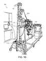
- FIG. 1Bis an image of the orthosis system of FIG. 1A ;
- FIG. 1Cis an image of a foot brace of the orthosis system of FIG. 1A ;
- FIG. 1Dis an image of a spring and pulley connection of the orthosis system of FIG. 1A ;
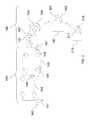
- FIG. 2is a diagram illustrating the degrees of freedom of the orthosis system of FIG. 1A ;
- FIG. 3is a diagram illustrating a gravity balancing spring of the orthosis system of FIG. 1A ;
- FIG. 4is a flowchart of an exemplary orthosis method in accordance with aspects of the present invention.
- the orthosis systems and methods disclosed hereinare usable to assist a user in developing or regaining the ability to walk.
- these systems and methodsgenerate forces for assisting the user in moving the appropriate limbs in a walking motion along a desired movement path at a desired speed (trajectory). At least a portion of the movement is performed under the user's own power.
- the systems and methodsmay be used by users who are performing walking motions on a treadmill.
- the various aspects of the present inventionrelate generally to powered orthosis systems adapted to be secured to a corresponding body portion of a user for guiding the motion of the user.
- the orthosis systemhas a plurality of structural members and one or more joints adjoining adjacent structural members.
- One or more springsmay be connected to the structural members in order to provide gravity balancing of the orthosis system independent of configuration.
- the jointshave one or more degrees of freedom and a range of joint angles.
- One or more of the jointshas at least one back-drivable actuator governed by at least one joint actuator controller for controlling the joint angle.
- the one or more joint actuator controllersmay be synchronized to cause the corresponding joint actuators to generate forces for assisting the user to move the orthosis system at least in part under the user's power along a desired trajectory within an allowed tolerance.
- the systems and methods disclosed hereinare particularly suitable for users that are developing or redeveloping control of motor skills due to neurological disorders including, for example, stroke, traumatic spinal cord injury, cerebral palsy, or spina bifida. These systems and methods may be effective for both adults and children.
- FIGS. 1A-3illustrate an exemplary orthosis system 100 in accordance with aspects of the present invention.
- Orthosis system 100may be usable to assist a user in developing or regaining the ability to walk.
- orthosis system 100includes a frame 110 , a trunk brace 130 , an upper leg brace 150 , a lower leg brace 170 , and a controller 190 . Additional details of orthosis system 100 are described herein.
- bracesis intended to encompass any and all structures adapted to be secured or coupled to a portion of the user of the orthosis system.
- the braces of the present inventionmay include and/or refer to straps, buckles, fasteners, or any other structure adapted for attachment to the user.
- the bracesmay, but need not, include structures adapted to support, align, or otherwise hold part of the user in a certain position or angle. Suitable structures for use as braces of the present invention will be understood to one of ordinary skill in the art from the description herein.
- Frame 110supports orthosis system 100 .
- Frame 110includes a base 112 and a stand 114 , as shown in FIG. 1A .
- Base 112is placed on a walking surface.
- Base 112is shaped to allow room for a user of orthosis system 100 to perform a walking motion.
- base 112is shaped to accommodate a treadmill (not shown) on which the user performs the walking motion.
- Base 112 of frame 110may include wheels 113 to enable movement of orthosis system 100 .
- Stand 114extends in an upright direction from base 112 .
- Stand 114includes a plurality of areas to which components of orthosis system 100 may be mounted, as will be described in greater detail below.
- Frame 110may be fashioned from any suitable rigid material using conventional manufacturing processes.
- Trunk brace 130is adapted to be secured to the trunk of a user. Trunk brace 130 anchors the user of orthosis system 100 to frame 110 .
- trunk brace 130comprises a padded belt adapted to be secured around the trunk of the user, as shown in FIG. 1B . Trunk brace 130 may be secured in place using suitable fasteners such as, for example, a buckles or straps. Suitable trunk braces 130 for use in the present invention will be understood by one of ordinary skill in the art from the description herein.
- Trunk brace 130is coupled to frame 110 with a trunk joint 140 , as shown in FIGS. 1A and 1B .
- trunk joint 140connects trunk brace 130 (and the user secured thereto) to frame 110 .
- Trunk joint 140enables movement by the user in multiple degrees of freedom relative to frame 110 , as set forth below.
- trunk joint 140enables the trunk of the user to move in four uncoupled degrees of freedom, as shown in FIG. 2 .
- a degree of freedomis uncoupled if the user's movement in that degree of freedom does not require or compel movement in one of the other degrees of freedom.
- the four degrees of freedomcomprise up/down motion, forward/backward motion, side-to-side motion, and rotation around a vertical axis.
- trunk joint 140includes: first and second rotational components 141 and 147 that enable side-to-side motion of the user relative to frame 110 (as shown by arrow 142 in FIG. 2 ) and rotation of the user around a vertical axis spaced from frame 110 (as shown by arrow 148 in FIG.
- trunk joint 140enable movement in these four uncoupled degrees of freedom in order to enable a user to perform the natural trunk movements that occur during a walking motion.
- Upper leg brace 150is adapted to be secured to the upper leg of a user.
- upper leg brace 150comprises one or more cuffs coupled to an elongated rigid structure (e.g., a rod).
- elongated rigid structuree.g., a rod
- upper leg brace 150is adjustable in length and circumferential size to accommodate users having varying leg lengths and diameters. Suitable upper leg braces 150 for use in the present invention will be understood by one of ordinary skill in the art from the description herein.
- Upper leg brace 150is coupled to trunk brace 130 with a hip joint 160 , as shown in FIG. 1A .
- hip joint 160enables movement of upper leg brace 150 by the user in multiple degrees of freedom relative to trunk brace 130 .
- hip joint 160enables the upper leg brace 150 of the user to move in three uncoupled degrees of freedom relative to trunk brace 130 , as shown in FIG. 2 .
- the three degrees of freedomcomprise flexion/extension rotation, abduction/adduction rotation, and rotation around a vertical axis.
- hip joint 160includes: a first rotational component 161 (e.g., a revolute joint) that enables abduction/adduction of the upper leg brace 150 relative to trunk brace 130 (as shown by arrow 162 in FIG. 2 ); a second rotational component 163 that enables flexion/extension of the upper leg brace 150 relative to trunk brace 130 (as shown by arrow 164 in FIG.
- hip joint 160enable movement in these three uncoupled degrees of freedom in order to enable a user to perform the normal movements that may occur during a walking motion.
- Hip joint 160may include at least one hip actuator 165 .
- hip actuator 165is operable to rotate upper leg brace 150 relative to trunk brace 130 .
- Hip actuator 165may be operable to perform this rotation in one or more of the degrees of freedom of hip joint 160 .
- hip actuator 165includes a motor 167 that is coupled directly to hip joint 160 in order to perform the rotation.
- Motor 167provides torque directly to hip joint 160 when instructed to do so by controller 190 .
- Suitable motors 167 for use with hip actuator 165include, for example, AKM-22c motors provided by Kollmorgen.
- Other suitable motors for use with hip actuator 165will be known to one of ordinary skill in the art from the description herein.
- Lower leg brace 170is adapted to be secured to the lower leg of a user.
- lower leg brace 170comprises components similar to those set forth above in the description of upper leg brace 150 .
- lower leg brace 170is desirably adjustable in length and circumferential size to accommodate users having varying leg lengths and diameters. Suitable lower leg braces 170 for use in the present invention will be understood by one of ordinary skill in the art from the description herein.
- Lower leg brace 170is coupled to upper leg brace 150 with a knee joint 180 , as shown in FIG. 1A .
- Knee joint 180enables movement of lower leg brace 170 by the user in one degree of freedom relative to upper leg brace 150 .
- knee joint 180includes a rotational component 181 that enables flexion/extension of the lower leg brace 170 relative to upper leg brace 150 (as shown by arrow 182 in FIG. 2 ).
- Knee joint 180may include at least one knee actuator 185 .
- knee actuator 185is operable to rotate lower leg brace 170 relative to upper leg brace 150 .
- knee actuator 185includes a motor 187 that is coupled directly to knee joint 180 in order to perform the rotation, as similarly described above with respect to motor 167 of hip actuator 165 .
- Suitable motors 187 for use with knee actuator 185include any of the motors set forth above with respect to motor 167 .
- Controller 190controls the operation of orthosis system 100 .
- controller 190is programmed to operate hip actuator 165 to rotate upper leg brace 150 relative to trunk brace 130 .
- controller 190is programmed to operate knee actuator 185 to rotate lower leg brace 170 relative to upper leg brace 150 .
- controller 190comprises a data processor. Suitable data processors for use as controller 190 will be known to one of ordinary skill in the art from the description herein.
- Controller 190may further include data storage for storing data for use in controlling the operation of orthosis system 100 , or data obtained during the operation of orthosis system 100 . Controller 190 may be connected to the joints and/or actuators of orthosis system 100 by conventional wired or wireless transmission devices.
- Orthosis system 100is not limited to the above components, but may include alternative or additional components, as would be understood by one of ordinary skill in the art.
- orthosis system 100may include a foot brace 210 adapted to be secured to the foot of a user, as shown in FIG. 1C .
- Foot brace 210may be positioned, for example, with a foot-bed inserted within the shoe of the user of orthosis system 100 .
- foot brace 210includes at least one pressure sensor 212 .
- the pressure sensormay sense a pressure exerted on the foot brace by the user during the performance of a walking motion. The sensed pressure may then be transmitted to controller 190 for storage and/or analysis.
- Pressure sensorsmay be positioned on foot brace 210 such that they sense pressures at the heel, ball, and toes of the user's foot, as shown in FIG. 1C .
- Suitable pressure sensors for use with foot brace 210include, for example, FlexiForce sensors provided by Tekscan, Inc.
- Foot brace 210may be coupled to lower leg brace 170 with an ankle joint 215 .
- Ankle joint 215enables movement of foot brace 210 by the user in one degree of freedom relative to lower leg brace 170 .
- ankle joint 215includes a rotational component 217 that enables flexion/extension of the foot brace 210 relative to lower leg brace 170 (as shown by arrow 218 in FIG. 2 ).
- orthosis system 100may include at least one motion sensing device 220 .
- Motion sensing devices 220are positioned to record the motion of the user at the degrees of freedom of orthosis system 100 .
- Motion sensing devices 220may be positioned, for example, at hip joint 160 and/or at knee joint 180 .
- Motion sensing devices 220are configured to sense a motion of the hip or knee joint during use of orthosis system 100 by the user. The sensed motion may then be transmitted to controller 190 for storage and/or analysis.
- Motion sensing devices 220include, for example, force sensors or torque sensors.
- motion sensing devices 220may comprise encoders for sensing brace positioning and torque sensors for measuring user intent and providing feedback to controller 190 .
- Suitable encoders for use as motion sensing devices 220include, for example, Kubler encoders from Turck, Inc., or encoders provided with the above-described motors.
- Suitable torque sensors for use as motion sensing devices 220include, for example, the Mini45 torque sensor from ATI Industrial Automation, Inc., or TRS series torque sensors from Transducer Techniques, Inc.
- orthosis system 100may include at least one spring 230 coupled between trunk brace 130 and frame 110 .
- Spring 230is configured to remove at least a portion of the weight of orthosis system 100 from the user.
- spring 230is coupled between a rear surface of trunk brace 130 and an upper portion of stand 114 of frame 110 , as shown in FIG. 1D .
- Frame 110may include one or more pulleys 116 affixed to the upper portion of stand 114 . Pulleys 116 are configured to couple the tension from spring 230 downward along stand 114 toward a fixed attachment at base 112 of frame 110 . Accordingly, at least a portion of the weight of trunk brace 130 and trunk joint 140 is lifted upward due to the elasticity of spring 230 .
- the force of the spring 230 on the trunk brace 130is diagrammatically shown in FIG. 3 .
- Employing a spring 230 to provide an upward forcemay be desirable in order to enhance the comfort of the user of orthosis system 100 . Additionally, this may be desirable in order to assist the user in performing a normal walking motion, i.e. by balancing the force of gravity and removing the weight of orthosis system 100 from the user.
- Orthosis system 100is described herein with respect to a single leg of the user, it will be understood that the invention is not so limited.
- Orthosis system 100may include components identical to those described above in order to be secured to both legs of a user. Alternatively, orthosis system 100 may be configured to be usable on either the right or left leg of the user. Switching orthosis system 100 from one leg to another may be performed, for example, by rotating a portion of hip joint 160 to change the abduction/adduction degree of freedom to function properly with the chosen leg.
- hip joint 160 and knee joint 180may include a respective actuator that is operable to rotate the braces on either side of the joint relative to each other.
- the operation of orthosis system 100will be described with respect to hip joint 160 .
- knee joint 180in addition to or in the alternative to hip joint 160 .
- controller 190is programmed to selectively power motor 167 of hip actuator 165 in order to rotate upper leg brace 150 relative to trunk brace 130 .
- controller 190powers motor 167 in accordance with predetermined walking models.
- Controller 190may store in its data storage one or more predetermined walking models.
- the modelscorrespond to the normal, healthy walking motion of a user of orthosis system 100 .
- Each modelis generated by storing data corresponding to the motion of hip joint 160 (e.g., the movement of hip joint 160 or the angle of upper leg brace 150 relative to trunk brace 130 ) along each degree of freedom during a normal, healthy walking motion.
- the models stored by controller 190may be created, for example, by monitoring the movement of a healthy user of orthosis system 100 using motion sensing devices 220 .
- controller 190actuates hip actuator 165 in accordance with the stored models.
- controller 190may actuate hip actuator 165 to perform the same movements as those stored in the normal, healthy walking model. Actuating the hip actuator 165 as described in this example may be desirable in order to enable a user of orthosis system 100 to experience the feeling of a normal, healthy walking motion in his or her limb(s).
- controller 190may only actuate hip actuator 165 when movement of hip joint 160 by the user differs from the normal, healthy walking model by a predetermined range.
- orthosis system 100allows a user to perform a walking motion to the best of his or her ability.
- controller 190actuates hip actuator 165 in order to correct the user's movements.
- Controller 190may actuate hip actuator 165 in order to assist a desired walking motion of the user (i.e. to rotate the joint in the direction of the movement by the user), or may do so to resist an undesired walking motion of the user (i.e. to rotate the joint in the direction opposite from the movement by the user).
- orthosis system 100may improve the recovery time and performance of users in developing or regaining the ability to walk.
- FIG. 4shows an exemplary orthosis method 300 in accordance with aspects of the present invention.
- Method 300may be implemented to assist a user in developing or regaining the ability to walk.
- method 300includes securing a user to an orthosis system, enabling the user to walk, and actuating at least one of a hip actuator and a knee actuator. Additional details of method 300 are described herein with respect to the components of orthosis system 100 .
- a useris secured to an orthosis system.
- the useris secured to orthosis system 100 .
- Trunk brace 130is secured to the trunk of a user; upper leg brace 150 is secured to the upper leg of the user; and lower leg brace 170 is secured to the lower leg of a user.
- the length of upper leg brace 150 and lower leg brace 170may be adjusted to correspond to the length of the user's leg.
- orthosis system 100includes a foot brace 210
- the foot bracemay be secured to the foot of the user, e.g., by insertion into the user's shoe.
- step 320the user is enabled to walk.
- the userwalks while secured to orthosis system 100 .
- the usermay desirably be positioned on a treadmill to enable the user to perform a walking motion without requiring movement of orthosis system 100 .
- orthosis system 100may include a hip actuator 165 and/or a knee actuator 185 .
- controller 190actuates (i) hip actuator 165 to rotate upper leg brace 150 relative to trunk brace 130 , and/or (ii) knee actuator 185 to rotate lower leg brace 170 relative to upper leg brace 150 .
- Step 330may be performed in accordance with stored walking models, as described above with respect to the operation of orthosis system 100 .
- controller 190may actuate the hip and/or knee actuator to perform the same movements as those stored in the normal, healthy walking model.
- controller 190may only actuate the hip and/or knee actuator when motion of the corresponding joint differs from the normal, healthy walking model by a predetermined range.
- Step 330may be performed in order to assist a desired walking motion of the user, or may be performed in order to resist an undesired walking motion of the user.
- Method 300is not limited to the above steps, but may include alternative steps and additional steps, as would be understood by one of ordinary skill in the art from the description herein.
- method 300may further include the step of recording a walking motion of the user while the user is secured to the orthosis system.
- controller 190records the motion of the user of orthosis system 100 using motion sensing devices 220 .
Landscapes
- Health & Medical Sciences (AREA)
- Epidemiology (AREA)
- Pain & Pain Management (AREA)
- Physical Education & Sports Medicine (AREA)
- Rehabilitation Therapy (AREA)
- Life Sciences & Earth Sciences (AREA)
- Animal Behavior & Ethology (AREA)
- General Health & Medical Sciences (AREA)
- Public Health (AREA)
- Veterinary Medicine (AREA)
- Rehabilitation Tools (AREA)
- Manipulator (AREA)
Abstract
Description
Claims (21)
Priority Applications (1)
| Application Number | Priority Date | Filing Date | Title |
|---|---|---|---|
| US13/213,176US8771208B2 (en) | 2010-08-19 | 2011-08-19 | Powered orthosis systems and methods |
Applications Claiming Priority (2)
| Application Number | Priority Date | Filing Date | Title |
|---|---|---|---|
| US37517110P | 2010-08-19 | 2010-08-19 | |
| US13/213,176US8771208B2 (en) | 2010-08-19 | 2011-08-19 | Powered orthosis systems and methods |
Publications (2)
| Publication Number | Publication Date |
|---|---|
| US20120046578A1 US20120046578A1 (en) | 2012-02-23 |
| US8771208B2true US8771208B2 (en) | 2014-07-08 |
Family
ID=45594626
Family Applications (1)
| Application Number | Title | Priority Date | Filing Date |
|---|---|---|---|
| US13/213,176Expired - Fee RelatedUS8771208B2 (en) | 2010-08-19 | 2011-08-19 | Powered orthosis systems and methods |
Country Status (2)
| Country | Link |
|---|---|
| US (1) | US8771208B2 (en) |
| WO (1) | WO2012024562A2 (en) |
Cited By (8)
| Publication number | Priority date | Publication date | Assignee | Title |
|---|---|---|---|---|
| US20140100491A1 (en)* | 2012-10-05 | 2014-04-10 | Jianjuen Hu | Lower Extremity Robotic Rehabilitation System |
| US20150165265A1 (en)* | 2013-12-13 | 2015-06-18 | ALT Innovations LLC | Multi-Modal Gait-Based Non-Invasive Therapy Platform |
| CN108143584A (en)* | 2016-12-02 | 2018-06-12 | 北京大艾机器人科技有限公司 | Suspension apparatus and use its exoskeleton robot |
| US20180289577A1 (en)* | 2015-01-18 | 2018-10-11 | Calabrian High Tech Srl | Six Degrees of Freedom Self Balanced Hybrid Serial-Parallel Robotic Systemfor Rehabilitation of Upper and Lower Limbs, Left and Right |
| US10315067B2 (en)* | 2013-12-13 | 2019-06-11 | ALT Innovations LLC | Natural assist simulated gait adjustment therapy system |
| US20190231630A1 (en)* | 2013-12-13 | 2019-08-01 | ALT Innovations LLC | Natural assist simulated gait therapy adjustment system |
| US10463308B2 (en)* | 2016-04-01 | 2019-11-05 | Hiwin Technologies Corp. | Lower limb spasticity measurement method |
| US11883714B2 (en) | 2020-12-24 | 2024-01-30 | ALT Innovations LLC | Upper body gait ergometer and gait trainer |
Families Citing this family (15)
| Publication number | Priority date | Publication date | Assignee | Title |
|---|---|---|---|---|
| KR101358943B1 (en)* | 2013-02-12 | 2014-02-07 | 한국과학기술연구원 | Pelvis support device for gait rehabilitation robot |
| DE202013101507U1 (en)* | 2013-04-09 | 2014-07-11 | Joachim Breid | exerciser |
| US10383784B2 (en) | 2013-07-30 | 2019-08-20 | Northeastern University | Gait training system and methods |
| EP3055038A4 (en)* | 2013-10-07 | 2017-03-22 | Daniel R. Tekulve | Portable rehab station |
| EP3133998B1 (en) | 2014-04-21 | 2019-07-03 | The Trustees of Columbia University in the City of New York | Human movement research, therapeutic, and diagnostic devices, methods, and systems |
| US10744362B2 (en)* | 2015-03-06 | 2020-08-18 | United States Government As Represented By The Department Of Veterans Affairs | Exercise machine |
| GB201506061D0 (en)* | 2015-04-09 | 2015-05-27 | Aldred Chris D | Realignment of the pelvis |
| ITPI20150027A1 (en) | 2015-04-11 | 2016-10-11 | Azienda Ospedaliera Pisana | HIGH ERGONOMIC EXOSKELETAL SYSTEM FOR THE UPPER LIMB |
| CN105742430A (en)* | 2016-03-07 | 2016-07-06 | 太原理工大学 | LED epitaxial structure and preparation method therefor |
| EP3222332A1 (en)* | 2016-03-24 | 2017-09-27 | Hocoma AG | Suspension device for balancing a weight |
| RU2641065C2 (en)* | 2016-04-26 | 2018-01-15 | Общество с ограниченной ответственностью Научно-внедренческое предприятие "ОРБИТА" (ООО НВП "ОРБИТА") | Device for restoration of knee and hip joint mobility by mechanotherapy |
| DE102016007741A1 (en)* | 2016-06-27 | 2017-12-28 | Marcel Reese | The invention relates to the field of exoskeletons, humanoid robots and also their use in teleoperative applications in virtual worlds or the real world |
| JP6555790B2 (en)* | 2016-07-18 | 2019-08-07 | 王 春宝 | Assisted rehabilitation training robot |
| US10639510B2 (en) | 2017-03-20 | 2020-05-05 | The Trustees Of Columbia University In The City Of New York | Human musculoskeletal support and training system methods and devices |
| US11135112B1 (en) | 2018-04-13 | 2021-10-05 | Arizona Board Of Regents Acting For And On Behalf Of Northern Arizona University | Multi-room in-home harness system |
Citations (23)
| Publication number | Priority date | Publication date | Assignee | Title |
|---|---|---|---|---|
| US2210269A (en) | 1938-02-01 | 1940-08-06 | Byron M Taylor | Means to aid in regaining normal body locomotion |
| GB1406420A (en) | 1971-11-03 | 1975-09-17 | Lywood B W | Seat lifting mechanism |
| US5020790A (en) | 1990-10-23 | 1991-06-04 | Board Of Supervisors Of Louisiana State University And Agricultural And Mechanical College | Powered gait orthosis |
| WO1994009727A2 (en) | 1992-10-29 | 1994-05-11 | Brian Andrews | Orthosis and prosthesis |
| US5333604A (en) | 1992-09-16 | 1994-08-02 | Sutter Corporation | Patella exercising apparatus |
| US5476441A (en) | 1993-09-30 | 1995-12-19 | Massachusetts Institute Of Technology | Controlled-brake orthosis |
| US6039707A (en) | 1999-02-16 | 2000-03-21 | Crawford; Michael K. | Pelvic support and walking assistance device |
| WO2000028927A1 (en) | 1998-11-13 | 2000-05-25 | Hocoma Ag | Device and method for automating treadmill therapy |
| US6213554B1 (en) | 1999-09-07 | 2001-04-10 | Groupe Myca | Lift chair |
| US20030023195A1 (en) | 2001-07-30 | 2003-01-30 | Tariq Rahman | Orthosis device |
| US6666831B1 (en) | 1999-08-20 | 2003-12-23 | The Regents Of The University Of California | Method, apparatus and system for automation of body weight support training (bwst) of biped locomotion over a treadmill using a programmable stepper device (psd) operating like an exoskeleton drive system from a fixed base |
| US6666796B1 (en) | 1999-09-16 | 2003-12-23 | Aerovironment, Inc. | Walking assisting apparatus |
| US20040049291A1 (en) | 2002-04-25 | 2004-03-11 | Mark Deharde | Ambulating knee joint |
| US20050043661A1 (en) | 2003-07-10 | 2005-02-24 | Nashner Lewis M. | Apparatus and method for characterizing contributions of forces associated with a body part of a subject |
| US20060211956A1 (en) | 2003-08-21 | 2006-09-21 | Yoshiyuki Sankai | Wearable action-assist device, and method and program for controlling wearable action-assist device |
| US20060241539A1 (en) | 2005-04-25 | 2006-10-26 | University Of Delaware | Gravity balanced orthosis apparatus |
| US20060293617A1 (en) | 2004-02-05 | 2006-12-28 | Reability Inc. | Methods and apparatuses for rehabilitation and training |
| US7247128B2 (en) | 2002-04-03 | 2007-07-24 | Oga Co., Ltd. | Exercise assisting machine |
| US7431707B2 (en)* | 2004-12-17 | 2008-10-07 | Honda Motor Co., Ltd. | Support moment control method for leg motion support orthosis |
| US20080249438A1 (en) | 2007-04-06 | 2008-10-09 | University Of Delaware | Passive Swing Assist Leg Exoskeleton |
| US20080255488A1 (en)* | 2007-04-06 | 2008-10-16 | University Of Delaware | Powered Orthosis |
| US7537573B2 (en)* | 2002-11-25 | 2009-05-26 | Tibion Corporation | Active muscle assistance and resistance device and method |
| US7601104B2 (en) | 2005-04-25 | 2009-10-13 | University Of Delaware | Passive gravity-balanced assistive device for sit-to-stand tasks |
- 2011
- 2011-08-19USUS13/213,176patent/US8771208B2/ennot_activeExpired - Fee Related
- 2011-08-19WOPCT/US2011/048376patent/WO2012024562A2/enactiveApplication Filing
Patent Citations (26)
| Publication number | Priority date | Publication date | Assignee | Title |
|---|---|---|---|---|
| US2210269A (en) | 1938-02-01 | 1940-08-06 | Byron M Taylor | Means to aid in regaining normal body locomotion |
| GB1406420A (en) | 1971-11-03 | 1975-09-17 | Lywood B W | Seat lifting mechanism |
| US5020790A (en) | 1990-10-23 | 1991-06-04 | Board Of Supervisors Of Louisiana State University And Agricultural And Mechanical College | Powered gait orthosis |
| US5333604A (en) | 1992-09-16 | 1994-08-02 | Sutter Corporation | Patella exercising apparatus |
| WO1994009727A2 (en) | 1992-10-29 | 1994-05-11 | Brian Andrews | Orthosis and prosthesis |
| US5476441A (en) | 1993-09-30 | 1995-12-19 | Massachusetts Institute Of Technology | Controlled-brake orthosis |
| US6821233B1 (en)* | 1998-11-13 | 2004-11-23 | Hocoma Ag | Device and method for automating treadmill therapy |
| WO2000028927A1 (en) | 1998-11-13 | 2000-05-25 | Hocoma Ag | Device and method for automating treadmill therapy |
| US6039707A (en) | 1999-02-16 | 2000-03-21 | Crawford; Michael K. | Pelvic support and walking assistance device |
| US6666831B1 (en) | 1999-08-20 | 2003-12-23 | The Regents Of The University Of California | Method, apparatus and system for automation of body weight support training (bwst) of biped locomotion over a treadmill using a programmable stepper device (psd) operating like an exoskeleton drive system from a fixed base |
| US6213554B1 (en) | 1999-09-07 | 2001-04-10 | Groupe Myca | Lift chair |
| US6666796B1 (en) | 1999-09-16 | 2003-12-23 | Aerovironment, Inc. | Walking assisting apparatus |
| US20030023195A1 (en) | 2001-07-30 | 2003-01-30 | Tariq Rahman | Orthosis device |
| US7247128B2 (en) | 2002-04-03 | 2007-07-24 | Oga Co., Ltd. | Exercise assisting machine |
| US20040049291A1 (en) | 2002-04-25 | 2004-03-11 | Mark Deharde | Ambulating knee joint |
| US7537573B2 (en)* | 2002-11-25 | 2009-05-26 | Tibion Corporation | Active muscle assistance and resistance device and method |
| US20050043661A1 (en) | 2003-07-10 | 2005-02-24 | Nashner Lewis M. | Apparatus and method for characterizing contributions of forces associated with a body part of a subject |
| US20060211956A1 (en) | 2003-08-21 | 2006-09-21 | Yoshiyuki Sankai | Wearable action-assist device, and method and program for controlling wearable action-assist device |
| US20060293617A1 (en) | 2004-02-05 | 2006-12-28 | Reability Inc. | Methods and apparatuses for rehabilitation and training |
| US7431707B2 (en)* | 2004-12-17 | 2008-10-07 | Honda Motor Co., Ltd. | Support moment control method for leg motion support orthosis |
| US20060241539A1 (en) | 2005-04-25 | 2006-10-26 | University Of Delaware | Gravity balanced orthosis apparatus |
| US7544155B2 (en) | 2005-04-25 | 2009-06-09 | University Of Delaware | Gravity balanced orthosis apparatus |
| US7601104B2 (en) | 2005-04-25 | 2009-10-13 | University Of Delaware | Passive gravity-balanced assistive device for sit-to-stand tasks |
| US20080249438A1 (en) | 2007-04-06 | 2008-10-09 | University Of Delaware | Passive Swing Assist Leg Exoskeleton |
| US20080255488A1 (en)* | 2007-04-06 | 2008-10-16 | University Of Delaware | Powered Orthosis |
| US8147436B2 (en)* | 2007-04-06 | 2012-04-03 | University Of Delaware | Powered orthosis |
Non-Patent Citations (33)
| Title |
|---|
| Agrawal, Abhishek, "Design of a Novel Two Degree-of-Freedom Ankle-Foot Orthosis", 8 pgs. |
| Agrawal, Abhishek, "Design of Gravity Balancing Leg Orthosis Using Non-Zero Free Length Springs", Mechanism and Machine Theory, vol. 40 (2005), 693-709. |
| Agrawal, Sunil K., "Design and Prototype of Gravity-Balanced Leg Orthosis", International Journal of HWRS, vol. 4, No. 3 (Sep. 2003), 13-16. |
| Agrawal, Sunil K., "Design of an Orthotic Device for Full or Partial Gravity-Balancing of a Human Upper Arm During Motion", Proceedings of the IEEE/RSJ International Conference on Intelligent Robots and Systems (Oct. 2003), 2841-2846. |
| Agrawal, Sunil K., "Theory and Design of an Orthotic Device for Full or Partial Gravity-Balancing of a Human Leg During Motion", IEEE Transactions on Neural Systems and Rehabilitation Engineering, vol. 12, No. 2 (Jun. 2004), 157-165. |
| Aoyagi, D., "An Assistive Robotic Device that Can Synchronize to the Pelvic Motion During Human Gait Training", Proceedings of the 9th International Conference on Rehabilitation Robotics (Jun. 28-Jul. 1, 2005), 565-568. |
| Bajd, T., "Standing-Up of a Healthy Subject and a Paraplegic Patient", J. Biomechanics, vol. 15, No. 1 (1982), 1-10. |
| Banala, Sai K., "A Gravity Balancing Leg Orthosis for Robotic Rehabilitation", Proceedings of the IEEE International Conference on Robotics & Automation (Apr. 2004), 2474-2479. |
| Banala, Sai K., "A Powered Leg Orthosis for Gait Rehabilitation of Motor-Impaired Patients", IEEE International Conference on Robotics and Automation (Apr. 10-14, 2007), 4140-4145. |
| Banala, Sai K., "Gait Rehabilitation with an Active Leg Orthosis", Proceedings of IDETC/CIE 2005, ASME International Design Engineering Technical Conferences and Computers and Information in Engineering Conference (Sep. 24-28, 2005), 1-7. |
| Banala, Sai K., "Gravity Balancing Leg Orthosis and Its Performance Evaluation", 12 pgs. |
| Banala, Sai K., "Robot Assisted Gait Training with Active Leg Exoskeleton (ALEX)", IEEE Transactions on Neural Systems and Rehabilitation Engineering, vol. 17, No. 1 (Feb. 2009), 2-8. |
| Bernhardt, Michael, "Hybrid Force-Position Control Yields Cooperative Behaviour of the Rehabilitation Robot LOKOMAT", Proceedings of the IEEE 9th International Conference on Rehabilitation Robotics (Jun. 28-Jul. 1, 2005), 536-539. |
| Cai, Lance L., "Assist-as-Needed Training Paradigms for Robotic Rehabilitation of Spinal Cord Injuries", Proceedings of the IEEE International Conference on Robotics and Automation (May 2006), 3504-3511. |
| Donaldson, N., "FES Standing: Control by Handle Reactions of Leg Muscle Stimulation (CHRELMS)", IEEE Transactions on Rehabilitation Engineering, vol. 4, No. 4 (Dec. 1996), 280-284. |
| Ekkelenkamp, J., "LOPES: A Lower Extremity Powered Exoskeleton", IEEE International Conference on Robotics and Automation (Apr. 10-14, 2007), 3132-3133. |
| Fattah, Abbas, "Design of a Gravity-Balanced Assistive Device for Sit-to-Stand Tasks", Proceedings of DETC '04, ASME Design Engineering Technical Conferences (Sep. 28-Oct. 2, 2004, 1-7. |
| Fattah, Abbas, "Design of a Passive Gravity-Balanced Assistive Device for Sit-to Stand Tasks", Journal of Mechanical Design, vol. 128 (Sep. 2006), 1122-1129. |
| Fattah, Abbas, "On the Design of a Passive Orthosis to Gravity Balance Human Legs", Journal of Mechanical Design, vol. 127 (Jul. 2005), 802-808. |
| International Application Serial No. PCT/US08/04319, International Search Report and Written Opinion mailed Jul. 25, 2008, 8 pgs. |
| International Application Serial No. PCT/US08/04330, International Search Report and Written Opinion mailed Jul. 25, 2008, 9 pgs. |
| International Application Serial No. PCT/US2008/004319, International Preliminary Report Patentability mailed Oct. 6, 2009, 5 pgs. |
| International Search Report dated Mar. 27, 2012, application No. PCT/US2011/048376. |
| Jezernik, Saso, "Automatic Gait-Pattern Adaptation Algorithms for Rehabilitation with a 4-DOF Robotic Orthosis", IEEE Transactions on Robotics and Automation, vol. 20, No. 3 (Jun. 2004), 574-582. |
| Kamnik, Roman, "Rehabilitation Robot Cell for Multimodal Standing-Up Motion Augmentation", Proceedings of IEEE International Conference on Robotics and Automation (Apr. 2005), 2277-2282. |
| Kamnik, Roman, "Robot Assistive Device for Augmenting Standing-Up Capabilities in Impaired People", Proceedings of the IEEE/RSJ International Conference on Intelligent Robots and Systems (Oct. 2003), 3606-3611. |
| Kim, Seok Hun, "Robot-Assisted Modifications of Gait in Healthy Individuals", Exp. Brain Res., vol. 202 (2010), 809-824. |
| Peshkin, Michael, "KineAssist: A Robotic Overground Gait and Balance Training Device", Proceedings of the IEEE 9th International Conference on Rehabilitation Robotics (Jun. 28-Jul. 1, 2005), 241-246. |
| Pledgie, Stephen, "Tremor Suppression Through Impedance Control", IEEE Transactions on Rehabilitation Engineering, vol. 8, No. 1 (Mar. 2000), 53-59. |
| Riener, Robert, "Human-Centered Rehabilitation Robotics", Proceedings of the 9th International Conference on Rehabilitation Robotics (Jun. 28-Jul. 1, 2005), 319-322. |
| Riener, Robert, "Identification of Passive Elastic Joint Moments in the Lower Extremities", Journal of Biomechanics, vol. 32 (1999), 539-544. |
| Riener, Robert, "Patient-Cooperative Strategies for Robot-Aided Treadmill Training: First Experimental Results", IEEE Transactions on Neural Systems and Rehabilitation Engineering, vol. 13, No. 3 (Sep. 2005), 380-394. |
| Riener, Robert, "Patient-Driven Control of FES-Supported Standing Up and Sitting Down: Experimental Results", IEEE Transactions on Rehabilitation Engineering, vol. 8, No. 4 (Dec. 2000), 523-529. |
Cited By (10)
| Publication number | Priority date | Publication date | Assignee | Title |
|---|---|---|---|---|
| US20140100491A1 (en)* | 2012-10-05 | 2014-04-10 | Jianjuen Hu | Lower Extremity Robotic Rehabilitation System |
| US20150165265A1 (en)* | 2013-12-13 | 2015-06-18 | ALT Innovations LLC | Multi-Modal Gait-Based Non-Invasive Therapy Platform |
| US9616282B2 (en)* | 2013-12-13 | 2017-04-11 | ALT Innovations LLC | Multi-modal gait-based non-invasive therapy platform |
| US10315067B2 (en)* | 2013-12-13 | 2019-06-11 | ALT Innovations LLC | Natural assist simulated gait adjustment therapy system |
| US20190231630A1 (en)* | 2013-12-13 | 2019-08-01 | ALT Innovations LLC | Natural assist simulated gait therapy adjustment system |
| US10881572B2 (en)* | 2013-12-13 | 2021-01-05 | ALT Innovations LLC | Natural assist simulated gait therapy adjustment system |
| US20180289577A1 (en)* | 2015-01-18 | 2018-10-11 | Calabrian High Tech Srl | Six Degrees of Freedom Self Balanced Hybrid Serial-Parallel Robotic Systemfor Rehabilitation of Upper and Lower Limbs, Left and Right |
| US10463308B2 (en)* | 2016-04-01 | 2019-11-05 | Hiwin Technologies Corp. | Lower limb spasticity measurement method |
| CN108143584A (en)* | 2016-12-02 | 2018-06-12 | 北京大艾机器人科技有限公司 | Suspension apparatus and use its exoskeleton robot |
| US11883714B2 (en) | 2020-12-24 | 2024-01-30 | ALT Innovations LLC | Upper body gait ergometer and gait trainer |
Also Published As
| Publication number | Publication date |
|---|---|
| WO2012024562A2 (en) | 2012-02-23 |
| US20120046578A1 (en) | 2012-02-23 |
| WO2012024562A3 (en) | 2012-05-18 |
Similar Documents
| Publication | Publication Date | Title |
|---|---|---|
| US8771208B2 (en) | Powered orthosis systems and methods | |
| US20230414381A1 (en) | Powered gait assistance systems | |
| US10278883B2 (en) | Systems, methods, and devices for assisting walking for developmentally-delayed toddlers | |
| Sanchez-Manchola et al. | Development of a robotic lower-limb exoskeleton for gait rehabilitation: AGoRA exoskeleton | |
| Veneman et al. | Design and evaluation of the LOPES exoskeleton robot for interactive gait rehabilitation | |
| US20100152629A1 (en) | Integrated system to assist in the rehabilitation and/or exercising of a single leg after stroke or other unilateral injury | |
| US9198821B2 (en) | Lower extremity exoskeleton for gait retraining | |
| EP1729858B1 (en) | Methods and apparatuses for rehabilitation exercise and training | |
| US6666831B1 (en) | Method, apparatus and system for automation of body weight support training (bwst) of biped locomotion over a treadmill using a programmable stepper device (psd) operating like an exoskeleton drive system from a fixed base | |
| US10576008B2 (en) | Methods of enhancing the rehabilitation or training of an exoskeleton wearer | |
| US20120197168A1 (en) | Pelvic orthosis systems and methods | |
| EP4259058B1 (en) | Powered-knee exoskeleton system | |
| Lagoda et al. | Human‐Robot Interfaces in Exoskeletons for Gait Training after Stroke: State of the Art and Challenges | |
| EP3415123A1 (en) | System and method for restoring human motor activity | |
| Jiang et al. | Recent advances on lower limb exoskeleton rehabilitation robot | |
| Taherifar et al. | Lokoiran-A novel robot for rehabilitation of spinal cord injury and stroke patients | |
| SANZ-MERODIO et al. | Control architecture of the ATLAS 2020 lower-limb active orthosis | |
| de Paiva et al. | Gait devices for stroke rehabilitation: State-of-the-art, challenges, and open issues | |
| EP2881008A1 (en) | Walk training apparatus, and use thereof. | |
| US11596828B1 (en) | Gait trainer attachment | |
| US20250065187A1 (en) | Stretching machine | |
| Kim et al. | Design of a cable-driven ankle rehabilitation system (C-DARS) | |
| CN120076774A (en) | System and method for moving in and out of a walking assistance system | |
| KR20250053289A (en) | Training robot system for leg rehabilitaton and method for controlling the same | |
| de Paiva et al. | State-of-the-art, challenges, and open issues |
Legal Events
| Date | Code | Title | Description |
|---|---|---|---|
| AS | Assignment | Owner name:UNIVERSITY OF DELAWARE, DELAWARE Free format text:ASSIGNMENT OF ASSIGNORS INTEREST;ASSIGNORS:AGRAWAL, SUNIL K.;WINFREE, KYLE N.;STEGALL, PAUL;AND OTHERS;SIGNING DATES FROM 20110818 TO 20110825;REEL/FRAME:026903/0853 | |
| AS | Assignment | Owner name:WINFREE, KYLE N., PENNSYLVANIA Free format text:ASSIGNMENT OF ASSIGNORS INTEREST;ASSIGNOR:UNIVERSITY OF DELAWARE;REEL/FRAME:033302/0455 Effective date:20140626 Owner name:AGRAWAL, SUNIL K., DELAWARE Free format text:ASSIGNMENT OF ASSIGNORS INTEREST;ASSIGNOR:UNIVERSITY OF DELAWARE;REEL/FRAME:033302/0455 Effective date:20140626 Owner name:HEIRS OR ESTATE OF JOHN P. SCHOLZ, DELAWARE Free format text:ASSIGNMENT OF ASSIGNORS INTEREST;ASSIGNOR:UNIVERSITY OF DELAWARE;REEL/FRAME:033302/0455 Effective date:20140626 Owner name:STEGALL, PAUL, MISSOURI Free format text:ASSIGNMENT OF ASSIGNORS INTEREST;ASSIGNOR:UNIVERSITY OF DELAWARE;REEL/FRAME:033302/0455 Effective date:20140626 | |
| AS | Assignment | Owner name:NATIONAL INSTITUTES OF HEALTH (NIH), U.S. DEPT. OF Free format text:CONFIRMATORY LICENSE;ASSIGNOR:UNIVERSITY OF DELAWARE;REEL/FRAME:042571/0982 Effective date:20170523 | |
| CC | Certificate of correction | ||
| FEPP | Fee payment procedure | Free format text:MAINTENANCE FEE REMINDER MAILED (ORIGINAL EVENT CODE: REM.) | |
| CC | Certificate of correction | ||
| LAPS | Lapse for failure to pay maintenance fees | Free format text:PATENT EXPIRED FOR FAILURE TO PAY MAINTENANCE FEES (ORIGINAL EVENT CODE: EXP.) | |
| STCH | Information on status: patent discontinuation | Free format text:PATENT EXPIRED DUE TO NONPAYMENT OF MAINTENANCE FEES UNDER 37 CFR 1.362 | |
| FP | Lapsed due to failure to pay maintenance fee | Effective date:20180708 |