US8770093B2 - Beverage machine with drip tray device for recipients of different heights - Google Patents
Beverage machine with drip tray device for recipients of different heightsDownload PDFInfo
- Publication number
- US8770093B2 US8770093B2US13/225,968US201113225968AUS8770093B2US 8770093 B2US8770093 B2US 8770093B2US 201113225968 AUS201113225968 AUS 201113225968AUS 8770093 B2US8770093 B2US 8770093B2
- Authority
- US
- United States
- Prior art keywords
- milk
- vessel
- dispenser
- drip
- housing
- Prior art date
- Legal status (The legal status is an assumption and is not a legal conclusion. Google has not performed a legal analysis and makes no representation as to the accuracy of the status listed.)
- Active
Links
Images


Classifications
- A—HUMAN NECESSITIES
- A47—FURNITURE; DOMESTIC ARTICLES OR APPLIANCES; COFFEE MILLS; SPICE MILLS; SUCTION CLEANERS IN GENERAL
- A47J—KITCHEN EQUIPMENT; COFFEE MILLS; SPICE MILLS; APPARATUS FOR MAKING BEVERAGES
- A47J31/00—Apparatus for making beverages
- A47J31/44—Parts or details or accessories of beverage-making apparatus
- A47J31/4485—Nozzles dispensing heated and foamed milk, i.e. milk is sucked from a milk container, heated and foamed inside the device, and subsequently dispensed from the nozzle
- A—HUMAN NECESSITIES
- A47—FURNITURE; DOMESTIC ARTICLES OR APPLIANCES; COFFEE MILLS; SPICE MILLS; SUCTION CLEANERS IN GENERAL
- A47J—KITCHEN EQUIPMENT; COFFEE MILLS; SPICE MILLS; APPARATUS FOR MAKING BEVERAGES
- A47J31/00—Apparatus for making beverages
- A47J31/44—Parts or details or accessories of beverage-making apparatus
- A47J31/4482—Details allowing to adapt the beverage-making apparatus to the size of the brewing vessel or the beverage container, e.g. with adjustable support for the beverage container or adjustable hot water outlet
- A—HUMAN NECESSITIES
- A47—FURNITURE; DOMESTIC ARTICLES OR APPLIANCES; COFFEE MILLS; SPICE MILLS; SUCTION CLEANERS IN GENERAL
- A47J—KITCHEN EQUIPMENT; COFFEE MILLS; SPICE MILLS; APPARATUS FOR MAKING BEVERAGES
- A47J31/00—Apparatus for making beverages
- A47J31/40—Beverage-making apparatus with dispensing means for adding a measured quantity of ingredients, e.g. coffee, water, sugar, cocoa, milk, tea
- A47J31/41—Beverage-making apparatus with dispensing means for adding a measured quantity of ingredients, e.g. coffee, water, sugar, cocoa, milk, tea of liquid ingredients
Definitions
- the inventionrelates to a machine for the preparation of beverages with a drip tray device configured to collect dripping liquid or liquid waste from recipients of variable dimensions, in particular, from short and long beverage recipients.
- the inventionalso relates to a milk froth dispensing device.
- Beverage preparation machinesare becoming very popular whether at home or in offices. There is a demand for machines that can prepare and deliver different beverage specialties; in particular, coffee and/or milk based beverages. For instance, machines exist for both extracting coffee capsules or pods and delivering milk froth thus providing the possibility to prepare both espresso coffee, cappuccino and macchiato. These beverages are served in recipients of different sizes.
- Espresso coffeesare typically served in 40-mL cups, while cappuccinos are served in 110-mL cups and macchiatos are served in long glasses or mugs of even larger volumes.
- beverage machinestypically have a drip tray adapted to collect the dripping liquid and waste liquid (water or beverage) that does not readily fall into the recipient.
- the drip traymust be emptied and rinsed by the user. This simple hygiene maintenance depends on the use and rest time of the machine but should be carried out frequently enough to avoid bad smells and organic growth.
- US patent publication 2003/0034359relates to a beverage dispenser with drip tray assembly for a portable coffee dispenser.
- EP patent application 1 440 639 A1refers to a beverage machine comprising a receptacle stand having a hollow interior forming a drip tray. An upper surface of the receptacle stand is provided with a grill on which the receptacle is positioned. The drip tray is removable from the housing to ease emptying of the collected water.
- the present inventionaims at proposing a beverage machine equipped with a drip tray device which overcomes these drawbacks.
- one object of the inventionis to propose a device which is simpler to use and more efficient.
- the present inventionis for a beverage machine comprising a drip tray device placed below at least a beverage outlet for collecting dripping liquid and/or foam; the drip tray device comprising a first drip support grid for holding a first beverage recipient and a collect tank for collecting the liquid passing through the support grid; wherein the first support grid is removable from the collect tank and, when removed, it leaves open a second drip support underneath configured for holding a second beverage recipient of larger height.
- One aspect of the inventionlies in having a first drip support grid that can simply be removed to uncover a second drip support underneath. The user does not have to spend more time and effort for manipulating or making the drip tray adapted to a longer size of recipient and thus operational for serving the beverage.
- Another advantagelies in that the beverage outlet and the fluid system attached to it, can be maintained in a fixed referential position while this is only the plane surface for receiving the beverage recipient that moves. This removes much complexity to the machine.
- Another aspectis to have the whole device removable for easy liquid emptying and cleaning.
- the support gridcan be removed either completely or removed partially in a manner to uncover the second recipient support underneath.
- the support gridcan retract or move away from its support position to a retracted or moved away position while still being attached to the machine or to the collect tank by connection means such as an hinge and the like.
- the second support meansis placed at several centimeters below the first support grid.
- the distanceis chosen depending upon the typical long beverages to be prepared.
- the distance between the first and second supportis of between 2 to 8 cm.
- the collect tankcomprises a first reservoir for collecting liquid from the first support grid.
- the second drip support meanscomprises a second collect reservoir to collect the dripping liquid when the second recipient of larger height is placed thereon.
- the reservoircan be made separate and closed from the main reservoir of the collect tank.
- the first reservoiris placed rearwardly and/or laterally adjacent but separate to the second reservoir.
- the first and second reservoirsare linked in a manner that they communicate together.
- the second reservoiris configured with a slope or altitude difference to naturally drain into the first reservoir.
- the first reservoiris preferably a reservoir of larger capacity.
- the first support gridcomprises a gutter.
- the guttercan be configured to direct the collected liquid that passes through the grid to the first reservoir of the collect tank.
- the guttercan be positioned over the second support means so that the dripping liquid is drained to the first main reservoir of the collect tank without the second support means being contaminated by the liquid dripping from the first support grid.
- the second support meansis used less frequently. Therefore, the waste liquid does not fall onto the second support means underneath and therefore it can remain cleaner until its use.
- the first reservoiris placed at the rear of the collect tank.
- the gutteris therefore configured to slope rearwardly and downwardly. Therefore, the reservoir is hidden for less smell and kept away from the user's eyes for a better hygiene perception.
- the second drip support meansis provided at the bottom of a recess of a sufficient transverse section to be able to receive a second recipient therein; said recess being contoured at its sides and rear side by an adjacent wall of the collect tank.
- the benefitis there to ensure that drops of liquid and/or foam that would fall outside the area of the second dripping support means are also collected by the collect tank.
- the recess of the second dripping support meansis demarcated by walls of the first large reservoir. Another advantage is that by having such a raised side drip collector that at least partly surrounds the recessed lower drip support, side liquid projections can be better recovered in the reservoir.
- An additional gridcan be provided to hide the first reservoir of the collect tank when the first support grid is removed. This provides a better external visual perception for the user who does not directly see the waste liquid in the collect tank. However, this grid is optional and could be omitted.
- the first support gridhas a front cover that is designed to close the recess when in place. In that way, the reservoir of the second drip support remains closed when the device is removed for emptying.
- the collect tankcomprises a single reservoir for collecting the liquid and/or foam from both first and second drip grid means; said reservoir being merely placed below the second drip support means.
- the machinecan comprise a waste capsule recovery container associated with the collect tank so that any liquid from the container can be drained to the collect tank.
- the inventionalso relates to a milk froth dispenser that can prepare and deliver, in a few seconds, in a very hygienic manner, a hot milk froth from liquid milk such as fresh milk contained in a thermo-insulated vessel.
- the inventionrelates to a milk froth dispenser comprising: a housing, the housing comprising a steamer adapted to produce steam under pressure through a steam outlet conduit; a disposable frothing nozzle that is configured to be removably plugged to the steam outlet conduit; and a drip tray device adapted to receive a recipient, wherein the dispenser comprises a milk vessel; the nozzle being fed with milk from the milk vessel by a tube or straw taking milk from the vessel to a milk inlet of the nozzle.
- the housingcomprises a recess to receive the milk vessel in a removable manner.
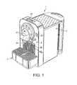
- FIG. 1shows a perspective view of a beverage machine equipped with the convertible drip tray device of the invention
- FIG. 2is a simplified cross section view of the beverage machine of FIG. 1 ,
- FIG. 3shows a perspective view of the convertible drip tray device
- FIG. 4shows a side view of the upper drip support grid of the device of FIG. 3 .
- FIG. 5shows a perspective view of the grid of FIG. 4 .
- FIG. 6shows the device of FIG. 3 with the upper drip support grid removed
- FIG. 7shows the device of FIG. 6 with further the additional grid of the collect tank removed for liquid emptying and rinsing
- FIG. 8shows the additional grid of the device
- FIG. 9shows a perspective view of a milk froth making device according to a varied embodiment of the present invention and where a short recipient is placed to receive the milk froth from a milk froth outlet,
- FIG. 10show a perspective view of the milk froth making device of FIG. 9 where a longer recipient is placed to receive the milk froth from the milk froth outlet
- FIG. 11is a cross sectional view of the drip tray device of FIG. 9 .
- FIG. 12shows a view of a detail of the drip tray device of FIG. 9 .
- a beverage machinemore particularly a coffee extraction machines which utilizes portioned coffee such as capsules in the preparation of the beverage.
- the machinecomprises typical components necessary for the extraction and delivery of a beverage such as coffee and milk-based coffee specialties (e.g. cappuccino, machiatto, . . . ).
- the machinecomprises within a cover and frame structure 2 , a front housing 20 for receiving a capsule extraction module (not shown), the frame structure comprising an opening 21 shaped to the profile of the capsule for easy capsule insertion in the module.
- the extraction housing 20terminates at its bottom end by a beverage (coffee) outlet 22 in the form of a collector and a funnelling portion of tube.
- the outlet 22can be configured with particular means to break the energy of the beverage coming out of the extraction module and/or for conditioning the foam and/or for reducing splashing.
- the machinefurther comprises a removable water supply tank 3 and internal components (not shown) necessary to supply hot water under pressure in the extraction module for preparing the hot beverages, in particular, a heater or boiler, a pump, tubing and an electronic controller.
- the machinealso has a suitable command means 23 and eventually an information screen 24 to deliver short messages or information regarding the preparation of the beverage and/or servicing of the machine.
- the machinemay further comprise a steam supply device 4 which is placed on the side for the preparation of milk froth.
- the steam supply devicemay be a simple steam pipe 40 with a steam outlet 40 a and, eventually, a frothing nozzle of the venturi type (not shown) as known in the art which is plugged to the steam outlet and which draws milk from a source of milk and froths it hot with a mixture of steam and air.
- the versatility of the machineis such that both pure coffee beverages (e.g., ristretto or espresso) and frothed milk and coffee beverages (cappuccino, machiatto) can be produced.
- pure coffee beveragese.g., ristretto or espresso
- frothed milk and coffee beveragescappuccino, machiatto
- the beverage machinecomprises a drip tray device 5 configured to accommodate beverage recipients of variable heights.
- An exemplary of drip tray device 5is shown in FIG. 3 when entirely removed from the rest of the machine for routine maintenance by the user (i.e., emptying, rinsing, cleaning).
- the deviceis partly inserted in a cavity of the frame of the machine.
- the drip tray devicecomprises a collect tank 6 and an upper drip support grid 7 which covers the collect tank during normal use with a small beverage recipient.
- the upper drip support grid 7is removable with respect to the collect tank 6 to uncover underneath a second drip support 8 made in a recess 60 of the collect tank.
- the collect tankhouses a main reservoir 51 for collecting the dripping liquid and waste as shown by FIG. 6 .
- the reservoirhas a portion 54 which is transversally shaped in a U-form but could also be in an O-form to surround completely the recess 60 .
- the reservoirthus demarcates the recess 60 along at least three sides, eventually four sides, by upwardly extending wall 52 .
- the advantageis mainly about the simplicity of construction with an integrated lower drip support 8 and also to ensure that side liquid projections, extending beyond the area of the cross-section of the recess, are also captured in the reservoir 51 .
- the collect tankfurther extends rearwardly of the U-shaped reservoir making a rear reservoir extension 53 of smaller width and lower height for easing the integration and insertion in the machine.
- the rear reservoir extensionalso ensures that the bulk of the liquid mass is kept away from the user's eyes and so bad smells are also reduced accordingly. This also enables to combine the drip tray device with other components of the machine to collect liquid waste from these components whenever necessary.
- the reservoiris positioned at least partially under a waste capsule recovery container to recover liquid dripping from used coffee capsules.
- the waste capsule recovery containerhas thus a draining means such as one or more holes or tubes or a basket communicating with the reservoir underneath.
- FIGS. 4 and 5shows a detail of the upper support grid 7 .
- the gridis formed of a horizontal metallic or plastic apertured plate 70 , a front cover wall 71 and a gutter 72 positioned under the plate 70 .
- the gutter 72is designed to recover the liquid from the central area of the plate and evacuate it to the rear of the collect tank in the main reservoir 51 .
- the gutterhas a shape that substantially matches the section of the recess for the lower drip support. It is positioned above the recess and it leans downwards and rearwards. Consequently, when a short recipient is used with the upper drip support on, the liquid does not fall on the lower drip support for higher recipients but is transported to the back of the reservoir which thus permits to keep the lower support substantially clean.
- the cover wall 71which has for primary function to close the front of the recess when the grid is placed on.
- the liquid in the bottom of the lower drip supportcannot escape the device during removal of the whole assembly and its transport to the sink.
- the collect tankpossesses a secondary grid 9 which is also preferably made removable from the body of the tank, whose function is so primarily to hide the inside reservoir when the upper grid 7 is removed and the lower support 8 is used.
- This grid 9is placed just below the first support grid 7 and fits a peripheral internal ridge bordering on the external wall and recess demarcating wall 52 of the tank.
- FIG. 8also shows that the grid 9 can comprise a rear demarcation wall 90 which partially separates the main reservoir 51 and the rear reservoir 53 .
- the lower drip support 8has recipient support elements 81 in the form of a plurality of support ridges protruding upwardly in a second reservoir 82 .
- the support elementscould also be replaced by a simple removable grid plate.
- the advantage of the ridgesis that they can be made of the same piece as the rest of the collect tank by plastic moulding.
- the second reservoir 82can be made separate of the main reservoir 51 with no liquid communication means as illustrated in the example. In an alternative, there could be a passage, gutter, opening or other link, through wall 52 , for the reservoir 82 to drain in the main reservoir 51 .
- the general rectangular shape and dimensions of the drip tray deviceis not essential and many variants can be envisaged although a large enough device is preferred for collecting all liquid including, as well, the water or milk drops below the steam delivery outlet.
- FIGS. 9 to 12illustrate a different embodiment for a milk froth dispenser 1 b .
- the dispenser of the inventionis configured to prepare hot frothed milk on demand from fresh milk and in a hygienic manner.
- the dispensercomprises a housing 2 b.
- the housingencompasses a steamer such as a thermobloc which produces steam on demand.
- a water supply reservoir 29can be provided in a side of the housing.
- a steam outlet conduit 22 bis provided on the top front side of the housing. The outlet can be protected by a heat insulated plastic cover to prevent burning issues.
- the steam outlet conduit 22 bterminates by a steam connector to which is plugged a disposable frothing device 41 that forms an extension to the connector.
- a disposable frothing devicecan be one as described in WO 2004/054413 or in US co-pending patent application Serial Number 11/279498 “Replaceable nozzle for producing a frothed liquid”; the contents of which are incorporated herewith by reference.
- the housingfurther comprises a large recess 20 b adapted to receive a heat-insulated milk vessel 25 .
- the vesselserves to feed the frothing device with liquid milk.
- the recessis preferably heat insulated to reduce the heat transfers from the steamer to the vessel.
- the vesselhas a lid 26 provided with a hole (not shown) and a U-shaped guide member 27 that protrudes radially from the lid.
- the liquid milkis supplied from the vessel to the frothing nozzle 41 a by a disposable straw 28 or a thin walled tube which is inserted through the hole of the lid. The straw 28 is thus guided in the U-shaped guide member 27 up to the milk inlet connector of the nozzle 41 a.
- the drip tray device 5 b of the milk froth dispenseris removable as illustrated in FIGS. 11 and 12 .
- the drip traycomprises a collect tank 51 b of substantially rectangular shape which is removably closed by a upper grid 70 b.
- the grid 70 bserves as support for a small recipient such as a coffee cup.
- the gridcan take support on an inner peripheral edge 51 d of the walls of the collect tank.
- a lower drip support meanslike a number of support elements 81 b (e.g., a plurality of spaced apart ridges) or a grid that can receive a recipient of large height as shown in FIG. 10 .
- the support elements 81 bshould be of sufficient height (e.g., between 10 to 25 mm) so that enough reserve space is made for liquid waste.
- the collect tankhas a front opening 60 b to allow a space for a large recipient to be conveniently inserted on the lower drip support means.
- the opening 60 bis closed by cover element 71 b that comprises rigidifying members 71 c with a support piece 71 d for receiving the upper grid 70 b in a stable manner.
- the collect tankmay also include a secondary reservoir 51 c to receive water waste through a passage 51 d from the dispenser such as water coming from the steamer when the steamer is emptied from water to reduce the scaling problems.
- the reservoircan have an upper door 51 e that can be opened to empty the reservoir.
- the drip tray devicefurther comprises a receiving seat 55 for the vessel.
- the seat 55has a shaped that is complementary to the base of the vessel so that the vessel can be inserted in the seat in a removable manner.
- the milk froth dispenserworks as follows.
- the userremoves the milk vessel for filling it with fresh milk by withdrawing the entire drip tray device 5 b as one block.
- the vesselis preferably refilled with milk that is at refrigerated temperature. Since the vessel has a thermos type structure, milk can be kept at low temperature during several hours.
- the lidcloses the vessel and a straw is placed through the lid and in the U-shaped guide member.
- the filled vesselis placed in the receiving seat 55 of the drip tray device and the assembly is inserted back to the housing.
- a disposable frothing nozzleis then plugged to the steam outlet/connector and the milk straw respectively at its steam inlet and milk inlet.
- the drip tray deviceis adjusted in height by manipulating the grid accordingly.
- the recipientis thus place below the milk froth outlet.
- the dispenseris switched on by pressing on command 23 b.
- the steamerproduces steam under pressure which steam is sent to the frothing nozzle device.
- the frothing nozzle deviceis discarded and replaced by a new one.
- the milk froth dispensercan be a stand alone system or can be a part or module of a coffee system.
- the milk vesselcould also be separate from the housing or placed on a side of it (not necessarily in a recess).
Landscapes
- Engineering & Computer Science (AREA)
- Food Science & Technology (AREA)
- Apparatus For Making Beverages (AREA)
- Devices For Dispensing Beverages (AREA)
- Containers And Packaging Bodies Having A Special Means To Remove Contents (AREA)
Abstract
Description
Claims (13)
Priority Applications (1)
| Application Number | Priority Date | Filing Date | Title |
|---|---|---|---|
| US13/225,968US8770093B2 (en) | 2005-06-07 | 2011-09-06 | Beverage machine with drip tray device for recipients of different heights |
Applications Claiming Priority (5)
| Application Number | Priority Date | Filing Date | Title |
|---|---|---|---|
| EP05104950.0 | 2005-06-07 | ||
| EP05104950AEP1731065B1 (en) | 2005-06-07 | 2005-06-07 | Beverage machine with drip tray device for recipients of different heights |
| EP05104950 | 2005-06-07 | ||
| US11/422,802US8091469B2 (en) | 2005-06-07 | 2006-06-07 | Beverage machine with drip tray device for recipients of different heights |
| US13/225,968US8770093B2 (en) | 2005-06-07 | 2011-09-06 | Beverage machine with drip tray device for recipients of different heights |
Related Parent Applications (1)
| Application Number | Title | Priority Date | Filing Date |
|---|---|---|---|
| US11/422,802ContinuationUS8091469B2 (en) | 2005-06-07 | 2006-06-07 | Beverage machine with drip tray device for recipients of different heights |
Publications (2)
| Publication Number | Publication Date |
|---|---|
| US20120000933A1 US20120000933A1 (en) | 2012-01-05 |
| US8770093B2true US8770093B2 (en) | 2014-07-08 |
Family
ID=35219484
Family Applications (2)
| Application Number | Title | Priority Date | Filing Date |
|---|---|---|---|
| US11/422,802Active2028-09-11US8091469B2 (en) | 2005-06-07 | 2006-06-07 | Beverage machine with drip tray device for recipients of different heights |
| US13/225,968ActiveUS8770093B2 (en) | 2005-06-07 | 2011-09-06 | Beverage machine with drip tray device for recipients of different heights |
Family Applications Before (1)
| Application Number | Title | Priority Date | Filing Date |
|---|---|---|---|
| US11/422,802Active2028-09-11US8091469B2 (en) | 2005-06-07 | 2006-06-07 | Beverage machine with drip tray device for recipients of different heights |
Country Status (11)
| Country | Link |
|---|---|
| US (2) | US8091469B2 (en) |
| EP (2) | EP1943931B1 (en) |
| JP (2) | JP5054327B2 (en) |
| CN (2) | CN101803876B (en) |
| AT (2) | ATE440529T1 (en) |
| AU (1) | AU2006202401B2 (en) |
| DE (3) | DE602005007475D1 (en) |
| DK (2) | DK1943931T3 (en) |
| ES (2) | ES2330810T3 (en) |
| PL (2) | PL1943931T3 (en) |
| PT (2) | PT1731065E (en) |
Cited By (6)
| Publication number | Priority date | Publication date | Assignee | Title |
|---|---|---|---|---|
| DE102015214099A1 (en)* | 2015-07-24 | 2017-01-26 | BSH Hausgeräte GmbH | capsule storage |
| US9844293B2 (en) | 2015-03-06 | 2017-12-19 | Spectrum Brands, Inc. | Apparatus for dispensing beverages |
| US12279629B1 (en) | 2024-01-18 | 2025-04-22 | Sharkninja Operating Llc | Mixing vessel baffles for a drink maker |
| USD1076580S1 (en) | 2024-01-18 | 2025-05-27 | Sharkninja Operating Llc | Drink maker dasher |
| USD1091236S1 (en) | 2024-01-18 | 2025-09-02 | Sharkninja Operating Llc | Collection tray for a drink maker |
| US12414578B1 (en) | 2025-03-14 | 2025-09-16 | Sharkninja Operating Llc | Shared output connector assembly for two drink maker dispenser assemblies |
Families Citing this family (128)
| Publication number | Priority date | Publication date | Assignee | Title |
|---|---|---|---|---|
| DE602005007475D1 (en) | 2005-06-07 | 2008-07-24 | Nestec Sa | Beverage machine with drip tray for containers of different heights |
| DE202006008409U1 (en)* | 2006-05-27 | 2006-08-10 | Eugster/Frismag Ag | Dissolving unit for instant powder, especially powdered milk, comprises a flow inducing member, a foam chamber and a nozzle |
| WO2008072295A1 (en)* | 2006-12-11 | 2008-06-19 | Devicestyle Holdings Corporation | Espresso machine |
| US7997187B2 (en)* | 2007-03-09 | 2011-08-16 | Hamilton Beach Brands, Inc | Brewed beverage maker |
| ITFI20070020U1 (en)* | 2007-04-06 | 2008-10-07 | Saeco Ipr Ltd | SUPPORT SUPPORT FOR CUPS AND COFFEE MACHINE OR SIMILAR INCLUDING THE SUPPORT. |
| ITFI20070172A1 (en)* | 2007-07-24 | 2009-01-25 | Saeco Ipr Ltd | "A SUPPORT FOR CUPS OR OTHER CONTAINERS IN DRINK MACHINES" |
| ITFI20070184A1 (en) | 2007-08-02 | 2009-02-03 | Saeco Ipr Ltd | "SUPPORT FOR DOUBLE SUPPORT PLATE FOR CUPS AND OTHER CONTAINERS IN BEVERAGE PRODUCTION MACHINES" |
| DE102007040305A1 (en)* | 2007-08-24 | 2009-02-26 | Miele & Cie. Kg | beverage maker |
| EP2070454B1 (en) | 2007-12-12 | 2015-07-15 | Nestec S.A. | Beverage production machines comprising a plurality of core units |
| AU2008334691B2 (en) | 2007-12-12 | 2015-01-22 | Société des Produits Nestlé S.A. | Used capsule or pod receptacle for liquid food or beverage machines |
| DK2276380T3 (en) | 2008-05-07 | 2013-09-08 | Nestec Sa | Capsule collector for used capsules for home appliances |
| DE102008028585A1 (en)* | 2008-06-16 | 2009-12-17 | BSH Bosch und Siemens Hausgeräte GmbH | Ice / liquid dispensing niche |
| ES2402221T3 (en) | 2008-09-01 | 2013-04-29 | Nestec S.A. | Device for conditioning a milk-based liquid |
| PL2341805T3 (en) | 2008-09-01 | 2012-11-30 | Nestec Sa | Appliance for fine steam-frothing a milk-based liquid |
| ITFI20080198A1 (en) | 2008-10-15 | 2010-04-16 | Saeco Ipr Ltd | "COFFEE MACHINE'" |
| EP2208450A1 (en)* | 2009-01-14 | 2010-07-21 | Nestec S.A. | Modular system with small footprint autonomous module |
| EP2427085B1 (en)* | 2009-05-06 | 2016-09-21 | Nestec S.A. | Method for manufacturing beverage machines with simplified servicing |
| EP2459035B1 (en)* | 2009-07-30 | 2013-11-20 | Nestec S.A. | Beverage production machine with antivibration drip tray assembly |
| AU2010295431A1 (en)* | 2009-09-17 | 2012-04-12 | Vinturi, Inc. | Wine aerator tower |
| CN102781291B (en) | 2009-12-02 | 2015-01-07 | 雀巢产品技术援助有限公司 | Beverage preparation machine with virtual shopping |
| AU2010326826B2 (en) | 2009-12-02 | 2015-07-30 | Société des Produits Nestlé S.A. | Beverage preparation machine comprising a card reading arrangement |
| CN102741889B (en) | 2009-12-02 | 2015-12-16 | 雀巢产品技术援助有限公司 | Beverage preparation machine with touch menu function |
| AU2010101537A4 (en) | 2009-12-02 | 2016-04-14 | Nestec S.A. | Beverage preparation machine comprising an extended user-advisory functionality |
| WO2011067188A1 (en) | 2009-12-02 | 2011-06-09 | Nestec S.A. | Beverage preparation machine with ambience emulation functionality |
| JP5809161B2 (en) | 2009-12-02 | 2015-11-10 | ネステク ソシエテ アノニム | Beverage preparation machine supporting remote service function |
| DE202010000024U1 (en)* | 2010-01-12 | 2011-05-19 | Wik Far East Ltd. | Beverage preparation machine |
| JP2013517026A (en)* | 2010-01-15 | 2013-05-16 | ネステク ソシエテ アノニム | Cooperation between ergonomic raw material holder and service unit |
| BR112012017591A2 (en)* | 2010-01-15 | 2016-08-16 | Nestec Sa | ergonomic service unit for beverage preparation machines |
| EP2353469A1 (en) | 2010-02-03 | 2011-08-10 | Nestec S.A. | Beverage preparation machine for large size beverages |
| EP2353473A1 (en) | 2010-02-03 | 2011-08-10 | Nestec S.A. | Beverage dispenser with hygienic cleaning cycle |
| EP2353474A1 (en) | 2010-02-03 | 2011-08-10 | Nestec S.A. | Beverage dispenser with safe cleaning arrangement |
| US8528466B2 (en)* | 2010-02-05 | 2013-09-10 | Bobbi J Sweet | Liquid overflow platform and container for small appliances |
| US20130112085A1 (en)* | 2010-05-21 | 2013-05-09 | Nestec S.A. | Storable hot water or steam delivery device |
| FR2960401B1 (en)* | 2010-05-25 | 2012-05-25 | Cie Mediterraneenne Des Cafes | INFUSION GROUP FOR BEVERAGE PRODUCTION MACHINE |
| CA2801278A1 (en) | 2010-06-09 | 2011-12-15 | Nestec S.A. | Ergonomic service arrangement for beverage machine |
| JP2013535242A (en)* | 2010-07-12 | 2013-09-12 | ネステク ソシエテ アノニム | Secure cup support for beverage machines |
| AU2011322725A1 (en) | 2010-10-27 | 2013-04-04 | Nestec S.A. | Beverage machine with a handy outlet |
| RU2571197C2 (en) | 2010-10-27 | 2015-12-20 | Нестек С.А. | Device for preparing beverages for different 3d environments |
| BR112013011242A2 (en)* | 2010-11-11 | 2016-11-01 | Nestec S A Ch | capsule, beverage production machine and system for preparing a nutritional product |
| EP2645914B1 (en) | 2010-12-01 | 2016-07-13 | Nestec S.A. | Beverage preparation machine with drop collector |
| IL217851A (en)* | 2011-02-08 | 2013-03-24 | Strauss Water Ltd | Beverage dispenser with a removable filter and a removable source beverage tank |
| RU2737062C9 (en)* | 2011-05-10 | 2021-02-04 | Бревилл Пти Лимитед | Device and method for improved coffee maker |
| US10383474B2 (en) | 2011-05-10 | 2019-08-20 | Breville Pty Limited | Coffee machine with overflow feature |
| EP2570059A1 (en) | 2011-09-16 | 2013-03-20 | Nestec S.A. | A beverage preparation machine |
| IN2014DN04766A (en)* | 2011-12-12 | 2015-05-22 | Nestec Sa | |
| US20130174743A1 (en)* | 2012-01-06 | 2013-07-11 | B/E Aerospace, Inc. | Aircraft brewing apparatus |
| IN2014DN05873A (en) | 2012-01-13 | 2015-05-22 | Nestec Sa | |
| RU2617365C9 (en) | 2012-01-13 | 2017-07-04 | Нестек С.А. | Beverage preparation machine for low and high cups |
| US8479945B1 (en) | 2012-02-02 | 2013-07-09 | Simmons Inventions Llc | Universal drain pan |
| EP2633789A1 (en) | 2012-02-28 | 2013-09-04 | Nestec S.A. | Beverage preparation machine with drop management |
| KR101936735B1 (en)* | 2012-04-13 | 2019-01-11 | 코웨이 주식회사 | Water purifier |
| FR2992155B1 (en)* | 2012-06-25 | 2015-02-20 | Cie Mediterraneenne Des Cafes | INFUSION DRINKING PREPARATION MACHINE COMPRISING A SLIDING BASIN |
| GB2504947B (en) | 2012-08-13 | 2015-01-14 | Kraft Foods R & D Inc | Beverage preparation machines |
| CN104379034B (en)* | 2012-10-26 | 2018-12-25 | 皇家飞利浦有限公司 | Machine for preparing drink including at least one pipe for conveying liquid |
| DE102013010110A1 (en)* | 2013-06-18 | 2014-12-18 | Beem Blitz-Elektro-Erzeugnisse Manufaktur Handels-Gmbh | coffee machine |
| CN103470887A (en)* | 2013-10-15 | 2013-12-25 | 惠生(南通)重工有限公司 | Leakage protection device for ultralow-temperature liquid at flange joint |
| CN203576311U (en)* | 2013-10-22 | 2014-05-07 | 宁波西摩电器有限公司 | Liquid heater with extendable chassis assembly |
| WO2015110128A1 (en)* | 2014-01-22 | 2015-07-30 | Aktiebolaget Electrolux | Drip plate assembly and beverage dispenser comprising a drip plate assembly |
| US9439532B2 (en) | 2014-03-11 | 2016-09-13 | Starbucks Corporation | Beverage production machines with multi-chambered basket units |
| US9504348B2 (en) | 2014-03-11 | 2016-11-29 | Starbucks Corporation | Cartridge ejection systems and methods for single-serve beverage production machines |
| US20150257586A1 (en)* | 2014-03-11 | 2015-09-17 | Starbucks Corporation Dba Starbucks Coffee Company | Single-serve beverage production machine |
| WO2016005348A1 (en) | 2014-07-09 | 2016-01-14 | Nestec S.A. | Device for connecting a beverage machine to a distribution network with safe flow interruption |
| EP3166457B1 (en) | 2014-07-09 | 2019-10-09 | Société des Produits Nestlé S.A. | Device for connecting a beverage machine to a distribution network with safe monitoring |
| US10595670B2 (en) | 2014-07-09 | 2020-03-24 | Societe Des Produits Nestle S.A. | Coupling of a device for connecting a beverage machine to a distribution network |
| ES2699086T3 (en) | 2014-07-09 | 2019-02-07 | Nestec Sa | Accessory to automatically supply a beverage machine with a liquid from a distribution network |
| DE102014109761B4 (en) | 2014-07-11 | 2020-07-09 | Melitta Single Portions Gmbh & Co. Kg | Device and method for preparing a brewed beverage |
| DE102014109760B4 (en)* | 2014-07-11 | 2018-06-28 | Melitta Single Portions Gmbh & Co. Kg | Apparatus and method for preparing a brewed beverage |
| EP3218299B2 (en) | 2014-11-12 | 2023-03-22 | Alfred Kärcher SE & Co. KG | Beverage preparation device |
| WO2016083485A1 (en) | 2014-11-27 | 2016-06-02 | Nestec S.A. | Liquid dispensing machine with manual drop stop |
| US11684204B2 (en) | 2014-11-27 | 2023-06-27 | Societe Des Produits Nestle S.A. | Liquid dispensing machine with compact drop stop |
| CN107105930B (en)* | 2014-12-18 | 2021-09-07 | 雀巢产品有限公司 | Removable cup support platform on collector receiver |
| RU2719183C2 (en)* | 2015-03-30 | 2020-04-17 | Бревилл Пти Лимитед | Milk foil device temperature sensor mounting assembly |
| CN104799699B (en)* | 2015-04-08 | 2017-08-25 | 洛阳理工学院 | A kind of water storage device for water dispenser |
| AU2016251426B2 (en)* | 2015-04-21 | 2020-07-23 | Société des Produits Nestlé S.A. | Beverage dispenser for preparing layered beverages |
| KR200481231Y1 (en)* | 2015-04-23 | 2016-09-01 | 정휘동 | Beverage Supplying Apparatus Having Height-adjustable Cup Support |
| US9809440B2 (en) | 2015-05-22 | 2017-11-07 | Dallas Kellerman | Combination dispenser drinking cup holder and drip collector apparatus |
| US10342377B2 (en) | 2015-06-16 | 2019-07-09 | Starbucks Corporation | Beverage preparation systems with adaptable brew chambers |
| US9968217B2 (en) | 2015-06-16 | 2018-05-15 | Starbucks Corporation | Beverage preparation systems with brew chamber securing mechanisms |
| US10602874B2 (en) | 2015-06-16 | 2020-03-31 | Starbucks Corporation Dba Starbucks Coffee Company | Beverage preparation systems with brew chamber access mechanisms |
| EP3158900A1 (en)* | 2015-10-20 | 2017-04-26 | Qbo Coffee GmbH | Machine for making beverages |
| US11284738B2 (en) | 2015-11-11 | 2022-03-29 | Societe Des Produits Nestle S.A. | Easy connection of a liquid tank to a beverage machine |
| CA3014513A1 (en) | 2016-03-02 | 2017-09-08 | Nestec S.A. | Beverage machine with an ergonomic service unit |
| PT3509464T (en) | 2016-09-09 | 2021-10-13 | Nestle Sa | BEVERAGE MACHINE WITH ERGONOMIC HANDLING |
| RU2752302C2 (en) | 2016-10-11 | 2021-07-26 | Сосьете Де Продюи Нестле С.А. | Liquid dispensing device with drop limiter |
| EP3525634B1 (en) | 2016-10-11 | 2020-10-07 | Société des Produits Nestlé S.A. | Liquid dispensing machine with speed regulator |
| CN106419577A (en)* | 2016-12-12 | 2017-02-22 | 珠海格力电器股份有限公司 | Drinking machine |
| US11432674B2 (en) | 2017-02-28 | 2022-09-06 | Societe Des Produits Nestle S.A. | Dispenser with parallel dispensing paths |
| KR101884904B1 (en)* | 2017-05-30 | 2018-09-11 | 금오공과대학교 산학협력단 | nozzle for drip coffee |
| CN110662469B (en)* | 2017-06-01 | 2023-03-14 | 雀巢产品有限公司 | Beverage machine with storable dispensing head |
| WO2018219989A1 (en) | 2017-06-01 | 2018-12-06 | Nestec Sa | Beverage machine with a stablizing foot |
| WO2018219984A1 (en)* | 2017-06-01 | 2018-12-06 | Nestec Sa | Beverage machine with a collapsible interface |
| CN110753505B (en) | 2017-06-13 | 2022-03-15 | 雀巢产品有限公司 | Beverage preparation machine with capsule recognition |
| DE102017117070B4 (en)* | 2017-07-27 | 2025-05-08 | Fresenius Medical Care Deutschland Gmbh | Container holder for dialysis device |
| PL3446602T3 (en)* | 2017-08-23 | 2021-06-14 | Jura Elektroapparate Ag | Residual water container for a device for beverage preparation and devices for beverage preparation |
| JP7308199B2 (en) | 2017-12-20 | 2023-07-13 | ソシエテ・デ・プロデュイ・ネスレ・エス・アー | Beverage preparation machine for miniaturizing foam |
| US11866318B2 (en) | 2017-12-20 | 2024-01-09 | Societe Des Produits Nestle S.A. | Beverage preparation machine with handy drop stop |
| US11564527B2 (en) | 2017-12-20 | 2023-01-31 | Societe Des Produits Nestle S.A. | Beverage preparation machine with drop evacuation |
| JP7242686B2 (en) | 2018-02-09 | 2023-03-20 | ソシエテ・デ・プロデュイ・ネスレ・エス・アー | Beverage preparation machine that recognizes capsules |
| US11819155B2 (en) | 2018-02-14 | 2023-11-21 | Societe Des Produits Nestle S.A. | Used capsule receptacle for beverage machines |
| EP3764850A1 (en) | 2018-03-14 | 2021-01-20 | Société des Produits Nestlé S.A. | Beverage machine with a non-homogeneous ingredient extraction configuration |
| BR112020015699A2 (en) | 2018-03-14 | 2020-12-08 | Société des Produits Nestlé S.A. | DRINKING MACHINE WITH A PARTIALLY CLOSED DISPENSING FACE |
| JP2021515626A (en) | 2018-03-14 | 2021-06-24 | ソシエテ・デ・プロデュイ・ネスレ・エス・アー | Beverage machine that controls and pierces capsules |
| JP2021515623A (en) | 2018-03-14 | 2021-06-24 | ソシエテ・デ・プロデュイ・ネスレ・エス・アー | Beverage machine with controlled outflow opening |
| WO2020030740A1 (en) | 2018-08-09 | 2020-02-13 | Société des Produits Nestlé SA | Easily insertable cup support |
| GB2578279B (en)* | 2018-08-17 | 2021-06-16 | Lavazza Professional Uk Ltd | Beverage vessel support apparatus |
| CN108968691B (en)* | 2018-08-30 | 2020-12-22 | 南京蓝领环境科技有限公司 | Milk making machine |
| PT3855986T (en) | 2018-09-27 | 2023-09-11 | Nestle Sa | Beverage machine with an actuation distribution |
| US12390044B2 (en) | 2018-09-27 | 2025-08-19 | Societe Des Produits Nestle S.A. | Adaptive service unit of a beverage machine |
| EP3628195A1 (en) | 2018-09-27 | 2020-04-01 | Société des Produits Nestlé S.A. | Beverage preparation machine with recipient detection |
| CA3121432A1 (en) | 2018-12-12 | 2020-06-18 | Societes Des Produits Nestle S.A. | Beverage preparation machine with capsule recognition |
| IT201900001175A1 (en) | 2019-01-25 | 2020-07-25 | De Longhi Appliances Srl | COFFEE MACHINE WITH IMPROVED LIQUID COLLECTION TRAY |
| CN110074673A (en)* | 2019-04-26 | 2019-08-02 | 广州腾工通用设备有限公司 | A kind of coffee brewing platform |
| CH716330A1 (en)* | 2019-06-17 | 2020-12-30 | Steiner Ag Weggis | Method and device for preparing a drink, preferably milk foam or hot milk. |
| USD941073S1 (en)* | 2019-07-24 | 2022-01-18 | The Coca-Cola Company | Beverage dispenser |
| ES2975752T3 (en) | 2020-02-05 | 2024-07-12 | Nestle Sa | Capsule recognition beverage preparation machine |
| CN115023164A (en) | 2020-02-05 | 2022-09-06 | 雀巢产品有限公司 | Beverage preparation machine with capsule recognition |
| IT202000018697A1 (en)* | 2020-07-31 | 2022-01-31 | Blupura Srl | DRINKING WATER DISPENSING DEVICE WITH CONTAINER WASHING SYSTEM |
| EP3987988A1 (en)* | 2020-10-21 | 2022-04-27 | Tchibo GmbH | Beverage preparation machine with silicone drainage grille |
| JP7504813B2 (en)* | 2021-01-21 | 2024-06-24 | ホシザキ株式会社 | Device for placing containers in a dispenser |
| USD976701S1 (en)* | 2021-04-08 | 2023-01-31 | Wen-Tsung Chang | Side wall for a storage box |
| EP4085801A1 (en)* | 2021-05-06 | 2022-11-09 | Tchibo GmbH | Beverage preparation machine with positioning element for positioning different containers for receiving beverages |
| IT202100018791A1 (en)* | 2021-07-15 | 2023-01-15 | Gruppo Cimbali Spa | Beverage making machine |
| IT202100020897A1 (en) | 2021-08-03 | 2023-02-03 | Illycaffe’ Spa | Machine for dispensing a drink |
| CN118102953A (en) | 2021-10-08 | 2024-05-28 | 雀巢产品有限公司 | Beverage preparation machine with easy ergonomic opening and closing |
| JP2024537023A (en) | 2021-10-13 | 2024-10-10 | ソシエテ・デ・プロデュイ・ネスレ・エス・アー | Ergonomic Drinking Machine |
| US20240382034A1 (en)* | 2023-05-18 | 2024-11-21 | Whirlpool Corporation | Coffee machine drip tray with integrated storage |
| WO2025120121A1 (en) | 2023-12-07 | 2025-06-12 | Societe Des Produits Nestle S.A. | Used capsule receptacle for beverage machines |
| WO2025158475A1 (en)* | 2024-01-24 | 2025-07-31 | De' Longhi Appliances S.R.L. | Beverage gasifier and beverage maker |
Citations (41)
| Publication number | Priority date | Publication date | Assignee | Title |
|---|---|---|---|---|
| US2598665A (en) | 1947-05-17 | 1952-06-03 | Bastian Blessing Co | Cup support and drain |
| US2827845A (en)* | 1955-06-16 | 1958-03-25 | Sanford E Richeson | Beverage making machine |
| US3094154A (en)* | 1960-09-16 | 1963-06-18 | Meterflo Dispensers Inc | Beverage dispensers |
| US3327902A (en)* | 1965-10-22 | 1967-06-27 | Alterwitz Melvin | Chilled beverage dispensing system |
| US4342710A (en)* | 1980-03-20 | 1982-08-03 | Intercylinder Ab | Apparatus for aerating beverages |
| US4944332A (en) | 1986-06-30 | 1990-07-31 | The Cornelius Company | Beverage dispenser for filling cups and extra-large receptacles with automatic dispensing shut off |
| US4949631A (en) | 1988-10-20 | 1990-08-21 | Fregnan Florindo--Costruzions Macchine de Caffe Elektra | Device for whipping milk designed to be connected to the conventional steam nozzle of an expresso coffee machine for the preparation of Italian cappuccino coffee |
| EP0472272A2 (en) | 1990-06-25 | 1992-02-26 | Caffe Acorto Inc. | Automated coffee apparatus |
| DE9109023U1 (en) | 1991-07-22 | 1992-11-19 | Bosch-Siemens Hausgeräte GmbH, 8000 München | Espresso machine, especially for the home |
| EP0585607A1 (en) | 1992-08-07 | 1994-03-09 | Braun Aktiengesellschaft | Espresso coffee machine |
| US5295431A (en) | 1992-02-10 | 1994-03-22 | Moulinex (Societe Anonyme) | Cappuccino accessory |
| US5305924A (en)* | 1993-05-12 | 1994-04-26 | The Coca-Cola Company | Beverage dispenser |
| FR2708185A3 (en) | 1993-06-30 | 1995-02-03 | Cma Spa | Machine for preparing individual servings of coffee or other infused drink mixed with milk |
| US5473972A (en) | 1994-10-24 | 1995-12-12 | Conair Corporation | Milk container attachment for cappucino maker |
| US5498757A (en) | 1995-04-04 | 1996-03-12 | Boyd Coffee Company | Milk frothing and heating system |
| US5542572A (en) | 1995-03-08 | 1996-08-06 | Imi Cornelius Inc. | Beverage dispenser removable driptray |
| US5549036A (en) | 1995-08-24 | 1996-08-27 | Hourizadeh; Richard | Cappuccino making apparatus |
| US5611262A (en) | 1996-06-24 | 1997-03-18 | Conair Corporation | Cappuccino maker |
| US5628239A (en) | 1996-03-28 | 1997-05-13 | Wu; Tsann-Kuen | Infusing unit for a venturi-type bubble-forming apparatus |
| EP0813834A1 (en) | 1996-06-21 | 1997-12-29 | Lucio Grossi | Device for frothing and heating liquids, such as milk and the like, provided with longitudinal channels for suction of the liquid-frothing air |
| US5768975A (en) | 1997-07-16 | 1998-06-23 | Tsann Kuen Usa Inc. | Bubble-forming sleeve for an espresso coffee maker |
| US5855162A (en) | 1996-07-22 | 1999-01-05 | Wmf Wuertembergische Metallwarenfabrik Ag | Coffee machine |
| US5884552A (en) | 1996-04-24 | 1999-03-23 | Sara Lee/De N.V. | Emulsifier for preparing frothed milk and hot milk |
| US5992298A (en)* | 1995-12-28 | 1999-11-30 | Francesco Illy | Coffee machine |
| US6183800B1 (en) | 1997-09-30 | 2001-02-06 | Sara Lee/De N.V. | Method for preparing frothed milk or café crème |
| US6192785B1 (en)* | 2000-03-27 | 2001-02-27 | Roberto Trida | Automatic dispenser of frothed milk and pre-made liquid coffee |
| US6293187B1 (en)* | 1999-05-08 | 2001-09-25 | Braun Gmbh | Milk frothing device |
| WO2001072190A1 (en) | 2000-03-27 | 2001-10-04 | Seb S.A. | Infusion machine |
| US20020134248A1 (en) | 2001-02-06 | 2002-09-26 | Arthur Eugster | Safety device of a steam-frothing device for producing a frothy beverage |
| US6499389B1 (en) | 1998-09-24 | 2002-12-31 | Jura Elekroapparate Ag | Device for producing milk froth for cappuccino |
| US20030010397A1 (en) | 2001-07-10 | 2003-01-16 | Ecolab Inc. | Fill station for a liquid dispensing system |
| US20030034359A1 (en) | 2001-08-16 | 2003-02-20 | Lassota Zbigniew G. | Beverage dispenser with drip tray assembly and method |
| EP1430819A1 (en) | 2002-12-16 | 2004-06-23 | Nestec S.A. | Connector piece for the steam outlet of a coffee machine |
| EP1440639A1 (en) | 2003-01-24 | 2004-07-28 | Kraft Foods R & D, Inc. | Machine for the preparation of beverages |
| US20040191370A1 (en)* | 2003-01-24 | 2004-09-30 | Kraft Foods R & D, Inc. | System and method for the preparation of beverages |
| US6827243B1 (en)* | 2002-08-01 | 2004-12-07 | Michael Nuzzolese | Portable liquid dispensing kit |
| US20060254428A1 (en)* | 2005-05-14 | 2006-11-16 | Glucksman Dov Z | Coffee making apparatus |
| JP2006341097A (en) | 2005-06-07 | 2006-12-21 | Nestec Sa | Beverage machine with drip tray device for recipient of different heights |
| USD549914S1 (en) | 2004-10-28 | 2007-08-28 | Naghmeh Eskandari | Combined dish rack and drain therefor |
| US20070243305A1 (en)* | 2004-04-21 | 2007-10-18 | Marconi Gian C | Device for Producing a Milk-Based Drink |
| US7322282B2 (en) | 2005-02-08 | 2008-01-29 | Saeco Ipr Limited | Assembly for creating milk froth and/or for heating milk |
Family Cites Families (7)
| Publication number | Priority date | Publication date | Assignee | Title |
|---|---|---|---|---|
| JPS4859043U (en)* | 1971-11-05 | 1973-07-26 | ||
| JPH0425072Y2 (en)* | 1985-01-09 | 1992-06-15 | ||
| JPH049958Y2 (en)* | 1985-01-09 | 1992-03-12 | ||
| CH681685A5 (en)* | 1990-11-02 | 1993-05-14 | Eldom Rothrist Ag | |
| ES2133212B1 (en)* | 1996-02-22 | 2000-04-16 | Gaggia Espanola | EXPRESS COFFEE MACHINE EQUIPPED WITH A DEVICE FOR MILK FOAMING. |
| JP3759898B2 (en)* | 2001-11-19 | 2006-03-29 | 象印マホービン株式会社 | Beverage extractor |
| NL1020833C2 (en)* | 2002-06-12 | 2003-12-15 | Sara Lee De Nv | Device for preparing a beverage suitable for consumption with a fine-bubble froth layer. |
- 2005
- 2005-06-07DEDE602005007475Tpatent/DE602005007475D1/ennot_activeExpired - Lifetime
- 2005-06-07ATAT08101131Tpatent/ATE440529T1/enactive
- 2005-06-07EPEP08101131Apatent/EP1943931B1/ennot_activeExpired - Lifetime
- 2005-06-07PLPL08101131Tpatent/PL1943931T3/enunknown
- 2005-06-07DKDK08101131Tpatent/DK1943931T3/enactive
- 2005-06-07PTPT05104950Tpatent/PT1731065E/enunknown
- 2005-06-07DKDK05104950Tpatent/DK1731065T3/enactive
- 2005-06-07PLPL05104950Tpatent/PL1731065T3/enunknown
- 2005-06-07ESES08101131Tpatent/ES2330810T3/ennot_activeExpired - Lifetime
- 2005-06-07DEDE602005016320Tpatent/DE602005016320D1/ennot_activeExpired - Lifetime
- 2005-06-07ESES05104950Tpatent/ES2308383T3/ennot_activeExpired - Lifetime
- 2005-06-07ATAT05104950Tpatent/ATE397878T1/enactive
- 2005-06-07EPEP05104950Apatent/EP1731065B1/ennot_activeExpired - Lifetime
- 2005-06-07PTPT08101131Tpatent/PT1943931E/enunknown
- 2006
- 2006-06-06DEDE102006026237Apatent/DE102006026237A1/ennot_activeWithdrawn
- 2006-06-06JPJP2006157072Apatent/JP5054327B2/ennot_activeExpired - Fee Related
- 2006-06-07CNCN2010101482215Apatent/CN101803876B/ennot_activeExpired - Fee Related
- 2006-06-07AUAU2006202401Apatent/AU2006202401B2/ennot_activeCeased
- 2006-06-07CNCN2006100879156Apatent/CN1875831B/ennot_activeExpired - Fee Related
- 2006-06-07USUS11/422,802patent/US8091469B2/enactiveActive
- 2011
- 2011-09-06USUS13/225,968patent/US8770093B2/enactiveActive
- 2011-12-22JPJP2011281693Apatent/JP5295347B2/ennot_activeExpired - Fee Related
Patent Citations (46)
| Publication number | Priority date | Publication date | Assignee | Title |
|---|---|---|---|---|
| US2598665A (en) | 1947-05-17 | 1952-06-03 | Bastian Blessing Co | Cup support and drain |
| US2827845A (en)* | 1955-06-16 | 1958-03-25 | Sanford E Richeson | Beverage making machine |
| US3094154A (en)* | 1960-09-16 | 1963-06-18 | Meterflo Dispensers Inc | Beverage dispensers |
| US3327902A (en)* | 1965-10-22 | 1967-06-27 | Alterwitz Melvin | Chilled beverage dispensing system |
| US4342710A (en)* | 1980-03-20 | 1982-08-03 | Intercylinder Ab | Apparatus for aerating beverages |
| US4944332A (en) | 1986-06-30 | 1990-07-31 | The Cornelius Company | Beverage dispenser for filling cups and extra-large receptacles with automatic dispensing shut off |
| US4949631A (en) | 1988-10-20 | 1990-08-21 | Fregnan Florindo--Costruzions Macchine de Caffe Elektra | Device for whipping milk designed to be connected to the conventional steam nozzle of an expresso coffee machine for the preparation of Italian cappuccino coffee |
| EP0472272A2 (en) | 1990-06-25 | 1992-02-26 | Caffe Acorto Inc. | Automated coffee apparatus |
| US5207148A (en) | 1990-06-25 | 1993-05-04 | Caffe Acorto, Inc. | Automated milk inclusive coffee apparatus |
| US5509349A (en) | 1990-06-25 | 1996-04-23 | Caffe Acorto, Inc. | Beverage valve venturi apparatus |
| DE9109023U1 (en) | 1991-07-22 | 1992-11-19 | Bosch-Siemens Hausgeräte GmbH, 8000 München | Espresso machine, especially for the home |
| US5295431A (en) | 1992-02-10 | 1994-03-22 | Moulinex (Societe Anonyme) | Cappuccino accessory |
| EP0585607A1 (en) | 1992-08-07 | 1994-03-09 | Braun Aktiengesellschaft | Espresso coffee machine |
| US5305924A (en)* | 1993-05-12 | 1994-04-26 | The Coca-Cola Company | Beverage dispenser |
| FR2708185A3 (en) | 1993-06-30 | 1995-02-03 | Cma Spa | Machine for preparing individual servings of coffee or other infused drink mixed with milk |
| US5473972A (en) | 1994-10-24 | 1995-12-12 | Conair Corporation | Milk container attachment for cappucino maker |
| US5542572A (en) | 1995-03-08 | 1996-08-06 | Imi Cornelius Inc. | Beverage dispenser removable driptray |
| US5498757A (en) | 1995-04-04 | 1996-03-12 | Boyd Coffee Company | Milk frothing and heating system |
| US5549036A (en) | 1995-08-24 | 1996-08-27 | Hourizadeh; Richard | Cappuccino making apparatus |
| US5992298A (en)* | 1995-12-28 | 1999-11-30 | Francesco Illy | Coffee machine |
| US5628239A (en) | 1996-03-28 | 1997-05-13 | Wu; Tsann-Kuen | Infusing unit for a venturi-type bubble-forming apparatus |
| US5884552A (en) | 1996-04-24 | 1999-03-23 | Sara Lee/De N.V. | Emulsifier for preparing frothed milk and hot milk |
| EP0813834A1 (en) | 1996-06-21 | 1997-12-29 | Lucio Grossi | Device for frothing and heating liquids, such as milk and the like, provided with longitudinal channels for suction of the liquid-frothing air |
| US5862740A (en) | 1996-06-21 | 1999-01-26 | Idea S.R.L. | Device for frothing and heating liquids, such as milk and the like, provided with longitudinal channels for suction of the liquid-frothing air |
| US5611262A (en) | 1996-06-24 | 1997-03-18 | Conair Corporation | Cappuccino maker |
| US5855162A (en) | 1996-07-22 | 1999-01-05 | Wmf Wuertembergische Metallwarenfabrik Ag | Coffee machine |
| US5768975A (en) | 1997-07-16 | 1998-06-23 | Tsann Kuen Usa Inc. | Bubble-forming sleeve for an espresso coffee maker |
| US6183800B1 (en) | 1997-09-30 | 2001-02-06 | Sara Lee/De N.V. | Method for preparing frothed milk or café crème |
| US6499389B1 (en) | 1998-09-24 | 2002-12-31 | Jura Elekroapparate Ag | Device for producing milk froth for cappuccino |
| US6293187B1 (en)* | 1999-05-08 | 2001-09-25 | Braun Gmbh | Milk frothing device |
| US6192785B1 (en)* | 2000-03-27 | 2001-02-27 | Roberto Trida | Automatic dispenser of frothed milk and pre-made liquid coffee |
| WO2001072190A1 (en) | 2000-03-27 | 2001-10-04 | Seb S.A. | Infusion machine |
| US20020134248A1 (en) | 2001-02-06 | 2002-09-26 | Arthur Eugster | Safety device of a steam-frothing device for producing a frothy beverage |
| US20030010397A1 (en) | 2001-07-10 | 2003-01-16 | Ecolab Inc. | Fill station for a liquid dispensing system |
| US20030034359A1 (en) | 2001-08-16 | 2003-02-20 | Lassota Zbigniew G. | Beverage dispenser with drip tray assembly and method |
| US6827243B1 (en)* | 2002-08-01 | 2004-12-07 | Michael Nuzzolese | Portable liquid dispensing kit |
| WO2004054413A1 (en) | 2002-12-16 | 2004-07-01 | Nestec S.A. | Nozzle adaptable to steam outlet of a coffee machine |
| EP1430819A1 (en) | 2002-12-16 | 2004-06-23 | Nestec S.A. | Connector piece for the steam outlet of a coffee machine |
| US20060113408A1 (en) | 2002-12-16 | 2006-06-01 | Mischa Stieger | Nozzle adaptable to steam outlet of a coffee machine |
| EP1440639A1 (en) | 2003-01-24 | 2004-07-28 | Kraft Foods R & D, Inc. | Machine for the preparation of beverages |
| US20040191370A1 (en)* | 2003-01-24 | 2004-09-30 | Kraft Foods R & D, Inc. | System and method for the preparation of beverages |
| US20070243305A1 (en)* | 2004-04-21 | 2007-10-18 | Marconi Gian C | Device for Producing a Milk-Based Drink |
| USD549914S1 (en) | 2004-10-28 | 2007-08-28 | Naghmeh Eskandari | Combined dish rack and drain therefor |
| US7322282B2 (en) | 2005-02-08 | 2008-01-29 | Saeco Ipr Limited | Assembly for creating milk froth and/or for heating milk |
| US20060254428A1 (en)* | 2005-05-14 | 2006-11-16 | Glucksman Dov Z | Coffee making apparatus |
| JP2006341097A (en) | 2005-06-07 | 2006-12-21 | Nestec Sa | Beverage machine with drip tray device for recipient of different heights |
Cited By (7)
| Publication number | Priority date | Publication date | Assignee | Title |
|---|---|---|---|---|
| US9844293B2 (en) | 2015-03-06 | 2017-12-19 | Spectrum Brands, Inc. | Apparatus for dispensing beverages |
| DE102015214099A1 (en)* | 2015-07-24 | 2017-01-26 | BSH Hausgeräte GmbH | capsule storage |
| US12279629B1 (en) | 2024-01-18 | 2025-04-22 | Sharkninja Operating Llc | Mixing vessel baffles for a drink maker |
| US12285028B1 (en) | 2024-01-18 | 2025-04-29 | Sharkninja Operating Llc | Mixing vessel baffles for a drink maker |
| USD1076580S1 (en) | 2024-01-18 | 2025-05-27 | Sharkninja Operating Llc | Drink maker dasher |
| USD1091236S1 (en) | 2024-01-18 | 2025-09-02 | Sharkninja Operating Llc | Collection tray for a drink maker |
| US12414578B1 (en) | 2025-03-14 | 2025-09-16 | Sharkninja Operating Llc | Shared output connector assembly for two drink maker dispenser assemblies |
Also Published As
| Publication number | Publication date |
|---|---|
| ATE397878T1 (en) | 2008-07-15 |
| EP1731065A1 (en) | 2006-12-13 |
| EP1731065B1 (en) | 2008-06-11 |
| EP1943931B1 (en) | 2009-08-26 |
| DE602005007475D1 (en) | 2008-07-24 |
| AU2006202401B2 (en) | 2012-07-19 |
| ES2308383T3 (en) | 2008-12-01 |
| EP1943931A2 (en) | 2008-07-16 |
| PT1731065E (en) | 2008-08-05 |
| PT1943931E (en) | 2009-09-04 |
| PL1731065T3 (en) | 2008-11-28 |
| JP2012066122A (en) | 2012-04-05 |
| US20070000944A1 (en) | 2007-01-04 |
| DK1731065T3 (en) | 2008-09-29 |
| CN1875831B (en) | 2010-05-26 |
| DE102006026237A1 (en) | 2007-01-11 |
| DE602005016320D1 (en) | 2009-10-08 |
| EP1943931A3 (en) | 2008-07-30 |
| ATE440529T1 (en) | 2009-09-15 |
| JP5295347B2 (en) | 2013-09-18 |
| US20120000933A1 (en) | 2012-01-05 |
| US8091469B2 (en) | 2012-01-10 |
| JP2006341097A (en) | 2006-12-21 |
| ES2330810T3 (en) | 2009-12-15 |
| CN101803876A (en) | 2010-08-18 |
| PL1943931T3 (en) | 2009-12-31 |
| AU2006202401A1 (en) | 2006-12-21 |
| CN101803876B (en) | 2012-03-21 |
| CN1875831A (en) | 2006-12-13 |
| JP5054327B2 (en) | 2012-10-24 |
| DK1943931T3 (en) | 2009-11-16 |
Similar Documents
| Publication | Publication Date | Title |
|---|---|---|
| US8770093B2 (en) | Beverage machine with drip tray device for recipients of different heights | |
| ES2370188T3 (en) | MACHINE TO PREPARE LIQUID FOOD OR DRINKS THAT HAS A DRIP TRAY AND A SUPPORT FOR MUGS. | |
| US9277839B2 (en) | Secure cup support for beverage machine | |
| CN108471899B (en) | Beverage machine with ergonomic water reservoir | |
| JP2013544172A (en) | Beverage preparation device with droplet collector | |
| US11220419B2 (en) | Beverage preparation machine with foam refinement | |
| CN111655092A (en) | Used capsule receptacles for beverage machines | |
| JP2013526358A (en) | Storeable hot water or steam delivery device | |
| JP2013526358A5 (en) | ||
| HK1263338B (en) | Machine for making beverages | |
| HK1263338A1 (en) | Machine for making beverages | |
| HK1146886B (en) | Liquid food or beverage machine having a drip tray and a cup support |
Legal Events
| Date | Code | Title | Description |
|---|---|---|---|
| AS | Assignment | Owner name:NESTEC S.A., SWITZERLAND Free format text:ASSIGNMENT OF ASSIGNORS INTEREST;ASSIGNORS:CAHEN, ANTOINE;STIEGER, MICHAEL;REEL/FRAME:026984/0805 Effective date:20060627 | |
| STCF | Information on status: patent grant | Free format text:PATENTED CASE | |
| MAFP | Maintenance fee payment | Free format text:PAYMENT OF MAINTENANCE FEE, 4TH YEAR, LARGE ENTITY (ORIGINAL EVENT CODE: M1551) Year of fee payment:4 | |
| AS | Assignment | Owner name:SOCIETE DES PRODUITS NESTLE S.A., SWITZERLAND Free format text:MERGER;ASSIGNOR:NESTEC S.A.;REEL/FRAME:049391/0756 Effective date:20190528 | |
| AS | Assignment | Owner name:SOCIETE DES PRODUITS NESTLE S.A., SWITZERLAND Free format text:CORRECTIVE ASSIGNMENT TO CORRECT THE ENGLISH TRANSLATION TO SHOW THE FULL AND CORRECT NEW NAME IN SECTION 51. PREVIOUSLY RECORDED AT REEL: 049391 FRAME: 0756. ASSIGNOR(S) HEREBY CONFIRMS THE MERGER;ASSIGNOR:NESTEC S.A.;REEL/FRAME:049853/0398 Effective date:20190528 | |
| AS | Assignment | Owner name:SOCIETE DES PRODUITS NESTLE S.A., SWITZERLAND Free format text:CORRECTIVE ASSIGNMENT TO CORRECT THE PATENT NUMBER 16062921 PREVIOUSLY RECORDED ON REEL 049391 FRAME 0756. ASSIGNOR(S) HEREBY CONFIRMS THE PATENT NUMBER SHOULD HAVE BEEN 16062912;ASSIGNOR:NESTEC S.A.;REEL/FRAME:054082/0165 Effective date:20190528 Owner name:SOCIETE DES PRODUITS NESTLE S.A., SWITZERLAND Free format text:CORRECTIVE ASSIGNMENT TO CORRECT THE PATENT NUMBER 16062921 PREVIOUSLY RECORDED ON REEL 049391 FRAME 0756. ASSIGNOR(S) HEREBY CONFIRMS THE PATENT NUMBER SHOULD HAVE BEEN 16062912;ASSIGNOR:NESTEC S.A.;REEL/FRAME:054082/0001 Effective date:20190528 | |
| MAFP | Maintenance fee payment | Free format text:PAYMENT OF MAINTENANCE FEE, 8TH YEAR, LARGE ENTITY (ORIGINAL EVENT CODE: M1552); ENTITY STATUS OF PATENT OWNER: LARGE ENTITY Year of fee payment:8 |