US8769171B2 - Electrical device with electrical interface that is compatible with integrated optical cable receptacle - Google Patents
Electrical device with electrical interface that is compatible with integrated optical cable receptacleDownload PDFInfo
- Publication number
- US8769171B2 US8769171B2US12/098,343US9834308AUS8769171B2US 8769171 B2US8769171 B2US 8769171B2US 9834308 AUS9834308 AUS 9834308AUS 8769171 B2US8769171 B2US 8769171B2
- Authority
- US
- United States
- Prior art keywords
- electrical
- active cable
- interface
- cable receptacle
- plug
- Prior art date
- Legal status (The legal status is an assumption and is not a legal conclusion. Google has not performed a legal analysis and makes no representation as to the accuracy of the status listed.)
- Active, expires
Links
- 230000003287optical effectEffects0.000titleclaimsabstractdescription51
- 230000006854communicationEffects0.000claimsabstractdescription75
- 238000004891communicationMethods0.000claimsabstractdescription75
- 230000007246mechanismEffects0.000claimsabstractdescription27
- 230000008878couplingEffects0.000claimsabstractdescription7
- 238000010168coupling processMethods0.000claimsabstractdescription7
- 238000005859coupling reactionMethods0.000claimsabstractdescription7
- 230000004888barrier functionEffects0.000claimsdescription9
- 229910052802copperInorganic materials0.000description16
- 239000010949copperSubstances0.000description16
- RYGMFSIKBFXOCR-UHFFFAOYSA-NCopperChemical compound[Cu]RYGMFSIKBFXOCR-UHFFFAOYSA-N0.000description14
- 239000013307optical fiberSubstances0.000description12
- 239000000835fiberSubstances0.000description6
- 238000003780insertionMethods0.000description6
- 230000037431insertionEffects0.000description6
- 238000000034methodMethods0.000description4
- 230000005693optoelectronicsEffects0.000description4
- 230000005540biological transmissionEffects0.000description3
- 238000006243chemical reactionMethods0.000description3
- 238000013461designMethods0.000description3
- 230000008901benefitEffects0.000description2
- 150000001879copperChemical class0.000description2
- 238000001514detection methodMethods0.000description2
- 238000005516engineering processMethods0.000description2
- 230000008569processEffects0.000description2
- 238000003860storageMethods0.000description2
- 238000012546transferMethods0.000description2
- RVCKCEDKBVEEHL-UHFFFAOYSA-N2,3,4,5,6-pentachlorobenzyl alcoholChemical compoundOCC1=C(Cl)C(Cl)=C(Cl)C(Cl)=C1ClRVCKCEDKBVEEHL-UHFFFAOYSA-N0.000description1
- 229920000271Kevlar®Polymers0.000description1
- 101100172132Mus musculus Eif3a geneProteins0.000description1
- 230000007175bidirectional communicationEffects0.000description1
- 230000015556catabolic processEffects0.000description1
- 239000004020conductorSubstances0.000description1
- 238000010276constructionMethods0.000description1
- 238000006731degradation reactionMethods0.000description1
- 238000011161developmentMethods0.000description1
- 230000009977dual effectEffects0.000description1
- 230000000694effectsEffects0.000description1
- 230000002349favourable effectEffects0.000description1
- 230000003993interactionEffects0.000description1
- 238000002955isolationMethods0.000description1
- 239000004761kevlarSubstances0.000description1
- 238000004519manufacturing processMethods0.000description1
- 239000002184metalSubstances0.000description1
- 229910052751metalInorganic materials0.000description1
- 238000000465mouldingMethods0.000description1
- 230000006855networkingEffects0.000description1
- 239000004033plasticSubstances0.000description1
- 238000012805post-processingMethods0.000description1
- 238000007781pre-processingMethods0.000description1
- 238000003825pressingMethods0.000description1
- 230000002265preventionEffects0.000description1
- 238000012545processingMethods0.000description1
- 239000011253protective coatingSubstances0.000description1
- 230000011664signalingEffects0.000description1
- 230000000007visual effectEffects0.000description1
Images


Classifications
- G—PHYSICS
- G02—OPTICS
- G02B—OPTICAL ELEMENTS, SYSTEMS OR APPARATUS
- G02B6/00—Light guides; Structural details of arrangements comprising light guides and other optical elements, e.g. couplings
- G02B6/24—Coupling light guides
- G02B6/42—Coupling light guides with opto-electronic elements
- G02B6/4201—Packages, e.g. shape, construction, internal or external details
- G02B6/4246—Bidirectionally operating package structures
- G—PHYSICS
- G02—OPTICS
- G02B—OPTICAL ELEMENTS, SYSTEMS OR APPARATUS
- G02B6/00—Light guides; Structural details of arrangements comprising light guides and other optical elements, e.g. couplings
- G02B6/24—Coupling light guides
- G02B6/42—Coupling light guides with opto-electronic elements
- G02B6/4201—Packages, e.g. shape, construction, internal or external details
- G02B6/4274—Electrical aspects
- G02B6/4284—Electrical aspects of optical modules with disconnectable electrical connectors
- H—ELECTRICITY
- H01—ELECTRIC ELEMENTS
- H01R—ELECTRICALLY-CONDUCTIVE CONNECTIONS; STRUCTURAL ASSOCIATIONS OF A PLURALITY OF MUTUALLY-INSULATED ELECTRICAL CONNECTING ELEMENTS; COUPLING DEVICES; CURRENT COLLECTORS
- H01R13/00—Details of coupling devices of the kinds covered by groups H01R12/70 or H01R24/00 - H01R33/00
- H01R13/66—Structural association with built-in electrical component
- H01R13/665—Structural association with built-in electrical component with built-in electronic circuit
- H01R13/6658—Structural association with built-in electrical component with built-in electronic circuit on printed circuit board
- H—ELECTRICITY
- H01—ELECTRIC ELEMENTS
- H01R—ELECTRICALLY-CONDUCTIVE CONNECTIONS; STRUCTURAL ASSOCIATIONS OF A PLURALITY OF MUTUALLY-INSULATED ELECTRICAL CONNECTING ELEMENTS; COUPLING DEVICES; CURRENT COLLECTORS
- H01R13/00—Details of coupling devices of the kinds covered by groups H01R12/70 or H01R24/00 - H01R33/00
- H01R13/66—Structural association with built-in electrical component
- H01R13/717—Structural association with built-in electrical component with built-in light source
- H01R13/7172—Conduits for light transmission
- H—ELECTRICITY
- H01—ELECTRIC ELEMENTS
- H01R—ELECTRICALLY-CONDUCTIVE CONNECTIONS; STRUCTURAL ASSOCIATIONS OF A PLURALITY OF MUTUALLY-INSULATED ELECTRICAL CONNECTING ELEMENTS; COUPLING DEVICES; CURRENT COLLECTORS
- H01R31/00—Coupling parts supported only by co-operation with counterpart
- H01R31/06—Intermediate parts for linking two coupling parts, e.g. adapter
- H01R31/065—Intermediate parts for linking two coupling parts, e.g. adapter with built-in electric apparatus
Definitions
- a linkmay typically comprise a transmitter that transmits a signal over a medium to a receiver, either in one direction between two network nodes, or bi-directionally.
- An optical linkmight include, for example, an optical transmitter, a fiber optic medium, and an optical receiver for each direction of communication.
- an optical transceiverserves as both an optical transmitter that serves to transmit optically over one fiber to the other node, while receiving optical signals over another fiber (typically in the same fiber-optic cable).
- 1Ggigabit per second
- Standards for communicating at 1Gare well established.
- the Gigabit Ethernet standardhas been available for some time, and specifies standards for communicating using Ethernet technology at the high rate of 1G.
- optical linkstend to be used more for longer spanning links (e.g., greater than 100 meters), whereas copper solutions tend to be used more for shorter links due in large part to the promulgation of the 1000Base-T standard, which permits 1G communication over standard Category 5 (“Cat-5”) unshielded twisted-pair network cable for links up to 100 meters.
- Cat-5Category 5
- 10GBASE-CX4uses a cable, which includes 4 shielded different pairs carrying a quarter of the bandwidth in each direction, for a total of 8 differential copper pairs.
- This cableis quite bulky (typically about 0.4′′ or 10 mm in diameter) and expensive to make and cannot be terminated in the field (as can CAT-5 for example). Furthermore, this copper-based 10G solution is limited to distances of about 15 m without special efforts. Alternative copper-based 10G solutions are being developed and standardized but are likely also to require significant power consumption.
- the primary exampleis known as 10GBASE-T under development in the IEEE (see IEEE draft standard 802.3an, “Part 3: Carrier Sense Multiple Access with Collision Detection (CSMA/CD) Access Method and Physical Layer Specifications Amendment: Physical Layer and Management Parameters for 10 Gb/s Operation, Type 10GBASE-T” 2006).
- This standarduses CAT5e or CAT6A unshielded twisted pair cable for distances to 55 m and 100 m respectively.
- this standardwill require circuitry with very high power dissipation, initially as high as 8-15 Watts (per port and thus twice this per link).
- a lower power variant which only achieves 30 m on CAT6A cableis still expected to be more than 4 Watts per port.
- These high power levelsrepresent both a significant increase in operating costs and perhaps more importantly, limitations on the density of ports which can be provided on a front panel. For example, power dissipations of 8-15 W could limit port density to 8 ports or less in the space of a typical 1U rack unit, whereas 1000BASE-T and 1G optical interfaces such as the SFP transceiver can provide up to 48 ports in the same space. Nevertheless, because of the cost of present day optical solutions at 10G, there remains interest in this copper solution.
- those setting up the high-bandwidth linkwill often weigh the pros and cons of using a copper-based solution versus an optical solution.
- the systemswill be set up with an electrical port if they decided to proceed with a copper-based solution, or an optical port (often more specifically a cage and connector to receiver a standard mechanical form factor optical transceiver such as the SFP) if they decided to proceed with an optical solution.
- embodiments of the present inventionrelate to a device that includes a plug that is configured to mechanically interface with a special receptacle external to the device.
- the external receptaclehas a mechanical and electrical interface shaped to interface with an integrated cable that includes an optical communication mechanism for communicating over much of the length of the integrated cable.
- the deviceis not such an integrated cable. That is to say, the device does not use an optical communication mechanism for communicating data.
- the plug of the devicehas an electrical interface configured to electrically interface with the receptacle even though the device itself has a full electrical communication channel communicatively coupling a data communication endpoint of the device with the electrical interface of the plug.
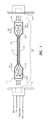
- FIG. 1illustrates a fully duplex electrical-to-electrical cable
- FIG. 2Aillustrates a top rear perspective view of an electrical connector representing one embodiment of a connector that may be used in FIG. 1
- FIG. 2Billustrates a side view of the electrical connector of FIG. 2A ;
- FIG. 2Cillustrates a bottom view of the electrical connector of FIG. 2A ;
- FIG. 3illustrates a top front perspective view of the electrical connector plugged into a receptacle
- FIG. 4illustrates a partial front view of the electrical connector of FIGS. 2A through 2C ;
- FIG. 5Aillustrates a top rear perspective view of an electrical device that has a mechanical and electrical interface that is similar to that of the connector of FIGS. 2A through 2C ;
- FIG. 5Billustrates a side view of the electrical device of FIG. 5A ;
- FIG. 5Cillustrates a bottom view of the electrical device of FIG. 5A ;
- FIG. 6illustrates a top front perspective view of the electrical device plugged into the receptacle
- FIG. 7Aillustrates a top front perspective view of the electrical device plugged into the receptacle, but with only the host panel, receptacle board, and contact array of the receptacle shown;
- FIG. 7Billustrates a side view of the combination of FIG. 7A ;
- FIG. 7Cillustrates a front view of the combination of FIG. 7A ;
- FIG. 8Aillustrates a top front perspective view of the combination of FIG. 7A , but with a socket shield added;
- FIG. 8Billustrates a top front perspective view of the combination of FIG. 8A , but with the contact body shown;
- FIG. 8Cillustrates a top front perspective view of the combination of FIG. 8B , but with the contact cover added;
- FIG. 9illustrates a top front perspective view of the combination of FIG. 8C , but with a receptacle housing shown;
- FIG. 10illustrates a top front perspective view of the combination of FIG. 9 , but with a host shield shown;
- FIG. 11illustrates an electrical device with an electrical interface that is compatible with optical cables in accordance with one aspect of the principles of the present invention.
- Embodiments of the present inventionrelate to a device that includes a plug that is configured to mechanically interface with a special receptacle external to the device.
- the external receptaclehas a mechanical and electrical interface shaped to interface with an integrated cable that includes an optical communication mechanism for communicating over much of the length of the integrated cable.
- the deviceis not such an integrated cable.
- the plug of the devicehas an electrical interface configured to electrically interface with the receptacle even though the device itself has a full electrical communication channel communicatively coupling a data communication endpoint of the device with the electrical interface of the plug.
- the integrated cableis exposed at least at one end using an electrical connection, while communicating over much of its length using optical fiber.
- those designing or selecting networking equipment or administrating network nodesneed not choose a copper-based solution or an optical solution in communicating over a network.
- the network nodeneed only have an electrical port of some type to thereby support either copper-based communication or optical communication.
- such a cablecan support point to point high speed serial connections such as the transmission of serialized video data from source to a display.
- the communication over the optical fibermay be high speed and suitable for 10G applications and higher.
- cable designswhich are purely electrical but mechanically and electrically interoperate with the optical cables described herein may be included as part of a complete system to provide the most effective solutions over the widest range of applications.
- FIG. 1schematically illustrates an integrated cable 100 that has electrical connections 111 and 121 at both ends.
- Each electrical connectionis sized and configured to connect to a corresponding electrical port at each network node.
- electrical connector 111is configured to connect to electrical port 112 at one network node
- the electrical connector 121is configured to connect to the electrical port 122 at the other network node. From the external connection viewpoint, it is as though the cable is entirely an electrical cable.
- Each end of the cable 100has optics that support duplex-mode optical communications.
- the optics at each end of the cable 100include a transmit optical sub-assembly (TOSA) for transmission of an optical signal over one optical fiber and a receive optical sub-assembly (ROSA) for receipt of an optical signal from another optical fiber.
- TOSAtransmit optical sub-assembly
- ROSAreceive optical sub-assembly
- ICs to drive the transmitting optics and to receive the detected signalare included. These ICs may be outside the TOSA or ROSA or may be integrated directly in their design.
- the cable 100is illustrated as supporting duplex-mode in which optical communication occurs in either direction, the cable may also perform communication in one direction consisting of a single transmitter at one end and a single receiver at the other.
- the cable 100includes two optical fibers 131 and 132 integrated within the cable 100 .
- an electrical signalis applied to the appropriate connections of the electrical connector 121 (e.g., through the electrical port 122 )
- those electrical signalsare converted by a laser driver and TOSA 123 (or more specifically by an electro-optical transducer within the TOSA 123 ) to a corresponding optical signal.
- the laser drivermay be included within the TOSA.
- the optical signalis transmitted over optical fiber 131 to ROSA 114 .
- the ROSA 114(or more specifically, an opto-electronic transducer within the ROSA 114 ) converts the optical signal received from the optical fiber 131 into a corresponding electrical signal.
- the optical transducerwould consist of a PIN detector and a preamplifier Integrated Circuit (IC), usually with a transimpedance amplifier front-end design.
- ICIntegrated Circuit
- a limiting amplifiermay also be integrated with the preamplifier or provided separately.
- the electrical signalis applied on the appropriate connections of the electrical connector 111 , whereupon it is provided to the electrical port 112 .
- the cable 100may be of any length, in one embodiment, the length is from 1 to 100 meters.
- the cablemay support high speed communication range between 1 to 10 gigabits per second and beyond.
- bi-directional communicationwhen an electrical signal is applied to the appropriate connections of the electrical connector 111 (e.g., through the electrical port 112 ), those electrical signals are converted by a laser driver and TOSA 113 (or more specifically by an electro-optical transducer within the TOSA 113 ) to a corresponding optical signal.
- the laser drivermay (but need not) be integrated within the TOSA.
- the optical signalis transmitted over optical fiber 132 to ROSA 124 .
- the ROSA 124(or more specifically, an opto-electronic transducer within the ROSA 124 ) converts the optical signal received from the optical fiber 132 into a corresponding electrical signal.
- the electrical signalis applied on the appropriate connections of the electrical connector 121 , whereupon it is provided to the electrical port 122 .
- the cable 100may additionally include a protective coating 133 which protects the optical fibers, the optics and portions of the electrical connectors.
- the fiber optic cablemight include some form of strength member such as Kevlar yarn.
- the electrical connectorssupply power from the host at least one end of the cable 133 to power the opto-electronic conversion.
- the power connectionmay be, for example, a 3.3 volt power connection.
- the electrical port 112is illustrated as supplying Power/Gnd connections for conveying electrical power from the host to electrical connector 111 .
- conveyance of informationis accomplished largely by means of an optical signal, while providing electrical connections on both ends of the cable.
- the purchaser of the cableneed not even be aware that the cable is an optical cable.
- a copper cablecould be provided for particularly short links (perhaps 1 to 5 meters) which emulates the cable 100 of FIG. 1 .
- the userneed not be concerned about choosing whether copper-based solutions or optical solutions are more appropriate, and then choose to configure the system with the appropriate ports.
- the usermay just plug in the cable, and enjoy all of the benefits of optical communication such as, for example, high bandwidth communication with low power consumption and high port density, and with less pre-processing and post-processing of information.
- the usercould choose a copper based version of the cable for particularly short links (say from the top to the bottom of a rack of switching equipment) if economically advantageous.
- the receptacle on the host systemmay include provisions for visual indicators of link activity and other status. This may be accomplished by two means common in the RJ-45 connector system. The first is inclusion of LEDs in the front panel face of the host receptacle with electrical connections to the host PCB. A second method is to include plastic light pipes within the receptacle assembly to guide light from LEDs on the host PCBA to the front surface of the receptacle.
- the cablemay have a provision for some sort of keying system to allow or prevent different types of host systems from being interconnected.
- a keying systemwould be important is to prevent the insertion of a single link cable in a dual link port.
- Another examplewould be the prevention of the connection of two host systems running different protocols, though this could be detected by protocol means themselves.
- exactly the same cablemay be useful for Ethernet and Fiber Channel applications, yet a system's administrator running a datacenter with both types of equipment may wish to prevent the interconnection of these systems by simple mechanical means. Of course color coding or other simple means could be used for this purpose as well.
- Keying features on a connectoroften comprise a mechanical protrusion on one of a set of locations on the host receptacle and corresponding slots on the cable plug, or vice versa. Examples of these features can be found in the definition of the HSSDC2 connector (see Small Form Factor Committee document SFF-8421 rev 2.6, Oct. 17, 2005).
- FIGS. 2A , 2 B and 2 Cillustrate a respective top rear perspective view 200 A, side view 200 B, and bottom view 200 C of an electrical connector 200 representing one embodiment of the electrical connectors 111 or 121 described above with respect to FIG. 1 .
- FIGS. 2A through 2Care present to show how the connector might mechanically interface with a receptacle.
- the connector 200includes an insertion portion 201 that may be inserted into the receptacle, whereupon a latch 202 may mechanically engage with the receptacle to lock the connector 200 into place within the receptacle until the next time the latch 202 is disengaged.
- the latch 202engages with the receptacle by simply pushing the insertion portion 201 into the receptacle, causing the latch 202 to depress downwards as the latch 202 engages the receptacle.
- the structure of the receptaclepermits the latch 202 to spring back up into a mechanically locked position within the receptacle once the insertion portion 201 of the connector 200 is fully inserted into the receptacle.
- the latch 202is disengaged from the receptacle by pressing downward on the latch 202 , allowing the latch 202 to once again move freely out of the receptacle.
- front sidewith respect to a connector means the electrical interface side of the connector closer to the insertion portion, while “rear side” means the side of the connector closer to the cable.
- Top sidemeans the side of the connector that includes the latch, whereas “bottom side” means the side of the connector opposite the latch.
- FIG. 3illustrate a respective top front perspective view 300 of a combination 300 of the connector 200 as plugged into a corresponding receptacle 310 .
- FIG. 4shows a front view the electrical connector 200 showing 12 contacts segmented into three groups 411 , 412 , 413 .
- the electrical contactsincludes contact group 411 including four contacts total (contacts 411 A, 411 B, 411 C and 411 D), contact group 412 including four contacts total (contacts 412 A, 412 B, 412 C and 412 D), and contact group 413 including four contacts total (contacts 413 A, 413 B, 413 C and 413 D).
- Each contact group 411 through 413is separated from other groups by a particular distance. For instance, there is a larger gap between contacts 411 D and 413 A, and between contacts 413 D and 412 A.
- this groupingcan result in reduced EMI emissions of the connector.
- the contact group 411may be used for communicating differential electrical transmit signals (sometimes referred to in the art as TX+ and TX ⁇ signals) and also include two ground signals for improved signal quality.
- contacts 411 A and 411 Dmay be ground contacts
- contacts 411 B and 411 Cmay be TX+ and TX ⁇ contacts actually carrying the differential electrical transmit signal during operation.
- the common mode impedance and differential mode impedance of the electrical transmit signalmay be more closely controlled.
- the contact group 412may be used for communicating differential electrical receive signals (sometimes referred to as RX+ and RX ⁇ signals) and also include two ground signals for improved signal quality.
- contacts 412 A and 412 Dmay be ground contacts
- contacts 412 B and 412 Cmay be RX+ and RX ⁇ contacts actually carrying the differential electrical receive signal during operation.
- the common mode impedance and differential mode impedance of the electrical receive signalmay also more closely controlled.
- Such common mode and differential mode impedance controlserves to reduce signal degradation contributed by the contacts, which is especially important at high data rates.
- the contact group 413may have contacts that serve purposes other than actually carrying the high speed electrical signal.
- the contacts 413include contacts 413 A through 413 D may be used for power and lower speed signaling.
- one contactmay be used to provide power to the connector, another might be used for presence detection, another might be used as a one-wire communication interface and yet another might be reserved or perhaps used as a power connection for the remote end of the cable.
- an active cablein which an electrical connection is provided on at least one side of the cable to receive the high speed electrical signal, while having the signal being communicated optically through most of the cable length.
- FIGS. 5A , 5 B and 5 Cillustrate a respective top rear perspective view 500 A, side view 500 B, and bottom view 500 C of an electrical device 500 .
- the electrical device 500has a similar mechanical and electrical interface for use in plugging into the receptacle 310 .
- the electrical device 500in not used for communication over an optical fiber, but is used for communication with a data endpoint within the electrical device. Note that the electrical device 500 is not in communication with an external cable.
- the electrical device 500includes an insertion portion 501 that may be inserted into the receptacle, whereupon a latch 502 may mechanically engage with the receptacle to lock the electrical device 500 into place within the receptacle until the next time the latch 502 is disengaged.
- FIG. 6illustrate a respective top front perspective view of a combination 600 of the electrical device 500 plugged into a corresponding receptacle 310 .
- the receptaclerepresents an example of the electrical port 112 or 122 of FIG. 1 .
- FIGS. 7A through 10will show an example construction of the receptacle 310 so that various internal features of the receptacle may be illustrated. The order of introduction illustrated in FIG. 7A through 10 does not imply an order of fabrication of the components of the receptacle 310 .
- FIGS. 7A , 7 B and 7 Cillustrate a respective top front perspective view 700 A, a side view 700 B, and front view 700 C of the combination 700 of the electrical device 500 interfacing with components of the receptacle 310 .
- the receptacle componentsare illustrated; namely, a host panel 710 , a receptacle board 720 , and a contact array 730 of receptacle side electrical contacts.
- the host panel 710may represent only a portion of a physical panel of the host into which the device 500 is plugged in.
- the receptacle board 720may be, for example, a printed circuit board, that may include electrical traces (not shown) for routing electrical signals and power to and from the contact array 730 .
- the receptacle 310would also include a mechanism for supporting the electrical device 500 as the device is plugged into the receptacle, a locking mechanism for interfacing with the latch 502 of the device 500 , a mechanism for structurally supporting the contact array 730 , and other components as will be apparent from the subsequent description of FIGS. 8A through 10 .
- the device 500As the device 500 is plugged into the receptacle 310 , the device 500 passes through the hole 711 in the host panel 710 , and is guided by structural pieces (not shown in FIGS. 7A through 7C ) in the receptacle. In addition, the latch mechanism 502 locks into place when the device is fully connected. Furthermore, the contact array 730 of the receptacle 310 is electrically coupled with the corresponding contact array 401 (see FIG. 4 ). Specifically, one group of four receptacle-side contacts 731 contacts the group of four connector-side contacts (e.g., including the differential transmit contacts and two ground contacts.
- Another group of four receptacle-side contacts 732contacts another group of four connector-side contacts (e.g., including the differential receive contacts and two ground contacts.
- the final group of four receptacle-side contacts 733contacts the final group of four connector-side contacts (e.g., including the power, low-speed, and reserved contacts).
- FIG. 8Aillustrates a top front perspective view of a combination 800 of the electrical device 500 plugged into the receptacle.
- the receptacleshows the same components as were illustrated in FIGS. 7A through 7C , but further includes a socket shield 810 .
- the socket shield 810serves as a component of the EMI barrier between the host and the ambient environment.
- the socket shield 810completed the EMI shield of the electrical device, thereby serving as an EMI barrier between the connector, and the host environment as well.
- the socket shield 810may be composed of conductive material, such as metal, and includes several fingers 811 that make electrical contact with the sleeve 501 of the electrical device 500 , when the device 500 is plugged into the receptacle.
- the small openings at the front of the socket shieldare the largest openings in the connector and host EMI barrier and serve to limit EMI better that a single large opening would.
- the smaller openingsare facilitated by the breaking up of the electrical contacts into three spatially distinct groupings as described above.
- the receptacle-side contact set 731contacts the corresponding device-side through the hole 801 in the socket shield 810 .
- the receptacle-side contact set 732contacts the corresponding device-side contact set 302 to form a second set of electrical connections through the hold 802 in the socket shield 810 .
- the receptacle-side contact set 733contacts the corresponding device-side contact set to form a third set of electrical connections through the hole 803 in the socket shield 810 .
- the socket shieldcovers the device housing which had represented the largest EMI discontinuity in the EMI barrier of the connector prior to the connector being plugged in. With the connector plugged in, the socket shield 810 covers the device housing.
- the EMI discontinuity at the front of the deviceis made into three much smaller EMI discontinuities.
- the EMI discontinuities at holes 801 through 803are still perhaps the largest EMI discontinuities in the EMI barrier at the connector, the EMI protection afforded the connector may be significantly improved by the presence of the receptacle-side socket shield 810 .
- FIG. 8Billustrates a top front perspective view of a combination 820 that is the same as the combination 800 of FIG. 8A , except that a contact body 830 is shown.
- the contact body 830may be insert molded around the receptacle contacts. However, a portion of the contacts 831 is left exposed to facilitate effective insert molding.
- FIG. 8Cillustrates a top front perspective view of a combination 840 that is the same as the combination 820 of FIG. 8B , except that a contact cover 850 is shown.
- the contact cover 850covers the previously exposed portion 831 of the contacts, and also extends over the end of the socket shield 810 .
- the contact cover 850also includes several prongs 851 A, 851 B, 851 C, and so forth (two on the top, and one on each side).
- FIG. 9illustrates a top front perspective view of a combination 900 that is the same as the combination 840 of FIG. 8C , except that receptacle housing 910 is disposed around the receptacle as shown.
- the receptacle housing 910provides further EMI protection.
- the receptacle housing 910also provides mechanical guidance for the device 500 as it is received into the receptacle.
- the socket housingincludes holes 911 A, 911 B, 911 C, and so forth, that receive respective prongs 851 A, 851 B, 851 C, and so forth, of the contact cover 850 . This mechanically locks the socket housing 910 to the contact cover 850 .
- the socket housing 910also includes two locking indentures 912 A and 912 B to receive the locking prongs of the locking mechanism 502 of the electrical device 500 . This serves to latch the electrical device 500 in place when plugged into the receptacle.
- FIG. 10illustrates a top front view of a combination 1000 that is the same as the combination 900 of FIG. 9 , except that a host shield 1010 is disposed thereon.
- the host shield 1010includes fingers 1011 that are bent back and placed in electrical contact with the host panel 710 .
- the host shield 1010is fixed at some voltage through a voltage pin 1020 in the host board 720 .
- the host shield 1010may be grounded. This shield serves to prevent any other emissions generated inside the host chassis from escaping through the panel opening.
- the details of the fingersare such that the openings are of small enough dimensions to greatly attenuate any emission.
- the receptacle housing 910makes electrical contact with the host shield 1010 and the socket shield 810 .
- the receptacle housing 910in combination with the host shield 1010 and the socket shield 810 provide an effective EMI barrier between the host and the environment, regardless of whether or not the electrical device 500 is plugged in.
- the socket shield 810serves to complete the EMI containment of the plug when it is inserted.
- FIG. 11schematically illustrates a device 1100 that comprises a plug 1110 .
- the device 1100is illustrated symbolically to illustrated functional relations and interactions between the various components of the device.
- the electrical device 500is an example of the device 1100 .
- the device 1100is shown more generally to show that the principles of the present invention are not limited to any specific form of an electrical device.
- a “plug”is any connector that is configured to mechanically interface with a port external to the device.
- the plug 1110is illustrated as symbolically mechanically interfacing with external port 1150 .
- the plug 1110has an electrical interface 1111 configured to electrically communicate with the external port 1150 when the plug 1110 is mechanically interfacing with the external port.
- the device 1100has a data communication endpoint 1120 which contains data.
- the device 1100might be, for example, a memory device.
- the communication endpoint 1120may contain non-volatile or volatile memory.
- the device 1100might be, for example, a memory stick, a digital music player, a video player, a photograph player or storage device, an external hard driver, an external optical drive, a camera, or any other device that contains volatile or non-volatile memory or storage.
- the device 1100has a full electrical communication channel 1130 that “communicatively couples” the data communication endpoint 1120 with electrical interface of the plug 1110 .
- two nodessuch as data communication endpoint 1120 and plug 1110
- communication channel 1130is illustrated as including electrical channel 1131 that communicates data from the plug 1110 to the data communication endpoint 1120 , and electrical channel 1132 that communicates data from the data communication endpoint 1120 to the plug 1110 .
- electrical channel 1132In a read-only device, only electrical channel 1132 will be used. In that case, the electrical channel 1131 need not even exist.
- both electrical channels 1131 and 1132are be used.
- the device 1100is configured such that data may be written to and read from the communication endpoint 1120 when the plug 1110 is mechanically and electrically interfacing with the external port 1150 .
- An electrical channelis a communication mechanism that employ electrical signals which involve the transfer of electrons, as contrasted with optical signals which involve the transfer of photons.
- the communication channel 1130is “full” electrical in that all communications between the data communication endpoint 1120 and the plug 1110 occur electrically, and not optically.
- the external port 1150is configured to mechanically and electrically interface with the device 1100 that has a full electrical communication channel. Nevertheless, the external port 1150 is also configured to mechanically and electrically interface with an integrated cable that include an optical communication mechanism for communicating over most of the length of the integrated cable. An example of such an integrated cable is described above with respect to FIG. 1 . Accordingly, the external port 1150 is quite flexible in that it can electrically and mechanically interface with a wide variety of devices.
- the device 1100 of FIG. 11represents symbolic components only. The principles of the present invention are not limited to a particular mechanical structure of such a device. In one embodiment, however, the device 1100 has a rigid casing 1140 that encases the data communication endpoint 1120 of the device 1110 , thereby providing some mechanical protection and electrical isolation from the surrounding environment, while permitting appropriate mechanical and electrical coupling to the external port 1150 via the plug 1110 .
- the device 1100is “consumer grade”.
- a “consumer grade” deviceis one that has a rigid casing (such as rigid casing 1140 ).
- rigid casing 1140For instance, conventional memory sticks are consumer grade since they contain a rigid casing that protects against damage from impact or externally applied pressure.
- a “consumer grade” deviceis a device in that has a mechanical locking mechanism such that less force is required to engage the plug 1110 with the external port 1150 than is required to remove the plug 1110 from the external port 1150 . This allows for convenience engagement of the device with the external port, while preventing inadvertent disengagement.
- the data communication endpoint 1120may include a wireless communication device.
- the wireless communication device 1120includes a transmitter for wirelessly transmitting data received by the data communication endpoint 1120 from the plug 1110 .
- the wireless communication device 1120includes a receiver for wireless receiving data to be communicated to the electrical interface of the plug.
- the device 1100is capable of mechanically and electrically interfacing with an external port 1150 that is also capable of electrically interfacing with an integrated cable that communicates of much of its length optically.
Landscapes
- Physics & Mathematics (AREA)
- Engineering & Computer Science (AREA)
- Microelectronics & Electronic Packaging (AREA)
- General Physics & Mathematics (AREA)
- Optics & Photonics (AREA)
- Details Of Connecting Devices For Male And Female Coupling (AREA)
Abstract
Description
Claims (20)
Priority Applications (2)
| Application Number | Priority Date | Filing Date | Title |
|---|---|---|---|
| US12/098,343US8769171B2 (en) | 2007-04-06 | 2008-04-04 | Electrical device with electrical interface that is compatible with integrated optical cable receptacle |
| PCT/US2008/059579WO2008124692A1 (en) | 2007-04-06 | 2008-04-07 | Electrical device with electrical interface that is compatible with optical cables |
Applications Claiming Priority (2)
| Application Number | Priority Date | Filing Date | Title |
|---|---|---|---|
| US91059207P | 2007-04-06 | 2007-04-06 | |
| US12/098,343US8769171B2 (en) | 2007-04-06 | 2008-04-04 | Electrical device with electrical interface that is compatible with integrated optical cable receptacle |
Publications (2)
| Publication Number | Publication Date |
|---|---|
| US20100325324A1 US20100325324A1 (en) | 2010-12-23 |
| US8769171B2true US8769171B2 (en) | 2014-07-01 |
Family
ID=39831386
Family Applications (1)
| Application Number | Title | Priority Date | Filing Date |
|---|---|---|---|
| US12/098,343Active2030-03-31US8769171B2 (en) | 2007-04-06 | 2008-04-04 | Electrical device with electrical interface that is compatible with integrated optical cable receptacle |
Country Status (2)
| Country | Link |
|---|---|
| US (1) | US8769171B2 (en) |
| WO (1) | WO2008124692A1 (en) |
Cited By (3)
| Publication number | Priority date | Publication date | Assignee | Title |
|---|---|---|---|---|
| US20190341728A1 (en)* | 2018-05-04 | 2019-11-07 | The Ricker Lyman Robotic Company Inc. | Surface-contact ethernet connector, network equipment chassis including the same and operating method thereof |
| US20220318116A1 (en)* | 2021-03-31 | 2022-10-06 | Dell Products L.P. | Direct-attach cable data transmission visual indicator system |
| US20220318167A1 (en)* | 2021-03-31 | 2022-10-06 | Dell Products L.P. | Direct-attach cable data transmission visual indicator system |
Families Citing this family (10)
| Publication number | Priority date | Publication date | Assignee | Title |
|---|---|---|---|---|
| US8882366B2 (en) | 2011-12-07 | 2014-11-11 | Finisar Corporation | Chip identification pads for identification of integrated circuits in an assembly |
| US9146367B2 (en)* | 2011-12-07 | 2015-09-29 | Finisar Corporation | Modular device for an optical communication module |
| US10171180B2 (en) | 2013-09-19 | 2019-01-01 | Radius Universal, LLC | Fiber optic communications and power network |
| US10277330B2 (en) | 2013-09-19 | 2019-04-30 | Radius Universal Llc | Fiber optic communications and power network |
| US12368615B2 (en) | 2013-09-19 | 2025-07-22 | Radius Universal Llc | Fiber optic communications and power network |
| US10139569B2 (en)* | 2016-04-05 | 2018-11-27 | Radius Universal, LLC | Connector assemblies for hybrid fiber/wire connections |
| US11025345B2 (en) | 2013-09-19 | 2021-06-01 | Radius Universal Llc | Hybrid cable providing data transmission through fiber optic cable and low voltage power over copper wire |
| US10663672B2 (en) | 2016-04-05 | 2020-05-26 | Radius Universal Llc | Connector assemblies for hybrid fiber/wire connections |
| MX388129B (en)* | 2017-11-13 | 2025-03-19 | Legrand Dpc Llc | HYBRID CABLE SET. |
| CN113965262A (en)* | 2021-09-10 | 2022-01-21 | 飞昂创新科技南通有限公司 | a network cable |
Citations (159)
| Publication number | Priority date | Publication date | Assignee | Title |
|---|---|---|---|---|
| US3663822A (en) | 1969-12-29 | 1972-05-16 | Nippon Selfoc Co Ltd | Multi-terminal optical cable utilizing a flexible graded optical fiber |
| US3792284A (en) | 1972-10-13 | 1974-02-12 | Gte Sylvania Inc | Electro-optic transmission link |
| US4127862A (en) | 1977-09-06 | 1978-11-28 | Bell Telephone Laboratories, Incorporated | Integrated optical detectors |
| US4427879A (en) | 1975-04-18 | 1984-01-24 | Allied Corporation | Optoelectronic connector assembly |
| US4595839A (en) | 1982-09-30 | 1986-06-17 | Tetra-Tech, Inc. | Bidirectional optical electronic converting connector with integral preamplification |
| US4768188A (en) | 1982-05-20 | 1988-08-30 | Hughes Network Systems, Inc. | Optical demand assigned local loop communication system |
| US4902092A (en) | 1988-01-04 | 1990-02-20 | Prestolite Wire Corporation | Multi-piece connector and receptacle therefor |
| US5064299A (en) | 1986-08-08 | 1991-11-12 | Siemens Aktiengesellschaft | Optocoupler apparatus |
| US5166761A (en) | 1991-04-01 | 1992-11-24 | Midwest Research Institute | Tunnel junction multiple wavelength light-emitting diodes |
| US5303251A (en) | 1990-08-17 | 1994-04-12 | Linotype-Hell Ag | Method and circuit arrangement for driving a laser diode |
| US5337398A (en) | 1992-11-30 | 1994-08-09 | At&T Bell Laboratories | Single in-line optical package |
| US5341086A (en) | 1990-10-20 | 1994-08-23 | Fujitsu Limited | Constant-current circuit for light-emitting element |
| US5448661A (en) | 1992-04-23 | 1995-09-05 | Hitachi, Ltd. | Optical parallel transmission device |
| US5451767A (en) | 1990-01-23 | 1995-09-19 | Nippon Telegraph & Telephone Corporation | Optical modulator gate array including multi-quantum well photodetector |
| US5497187A (en) | 1991-11-29 | 1996-03-05 | Scientific-Atlanta, Inc. | In-band/out-of-band data transmission method and apparatus for a television system |
| US5515467A (en) | 1994-12-30 | 1996-05-07 | Motorola, Inc. | Optical fiber assembly for connecting photonic devices to a fiber optic cable |
| US5631988A (en) | 1993-05-24 | 1997-05-20 | Vixel Corporation | Parallel optical interconnect |
| US5668419A (en) | 1995-06-30 | 1997-09-16 | Canon Information Systems, Inc. | Reconfigurable connector |
| US5732176A (en) | 1993-06-29 | 1998-03-24 | Savage, Jr.; John M. | Light pipe optical coupling between LED and fiber optics cable |
| US5892784A (en) | 1994-10-27 | 1999-04-06 | Hewlett-Packard Company | N-drive p-common surface emitting laser fabricated on n+ substrate |
| US5907569A (en) | 1997-05-28 | 1999-05-25 | Lucent Technologies Inc. | Circuit for controlling the output power of an uncooled laser or light emitting diode |
| US5926303A (en) | 1997-07-29 | 1999-07-20 | Alcatel Usa Sourcing, L.P. | System and apparatus for optical fiber interface |
| US6008917A (en) | 1997-10-29 | 1999-12-28 | Texas Instruments Incorporated | Apparatus and method for optical communication |
| US6036654A (en) | 1994-09-23 | 2000-03-14 | Baxter International Inc. | Multi-lumen, multi-parameter catheter |
| US6115516A (en) | 1997-05-12 | 2000-09-05 | Alcatel | Wavelength division multiplex branching unit and method of operation for optical transmission systems |
| JP2000241642A (en) | 1999-02-17 | 2000-09-08 | Sumitomo Electric Ind Ltd | Optical transceiver module |
| US6179627B1 (en) | 1998-04-22 | 2001-01-30 | Stratos Lightwave, Inc. | High speed interface converter module |
| US6217231B1 (en) | 1997-04-23 | 2001-04-17 | Fujitsu Limited | Optical fiber assembly, optical module including an optical fiber assembly, and a manufacturing process thereof |
| US6220873B1 (en) | 1999-08-10 | 2001-04-24 | Stratos Lightwave, Inc. | Modified contact traces for interface converter |
| US6267606B1 (en) | 1995-01-13 | 2001-07-31 | Stratos Lightwave, Inc. | Removable transceiver module and receptacle |
| US20010035994A1 (en) | 2000-02-28 | 2001-11-01 | Agazzi Oscar E. | System and method for high speed communications using digital signal processing |
| US20020006251A1 (en) | 2000-06-30 | 2002-01-17 | Jin-Hwan Kim | Bidirectional signal transmission device using light |
| US20020018609A1 (en) | 2000-06-23 | 2002-02-14 | Mathias Schumann | Oscilloscope probe with fiberoptic sensor for measuring floating electrical signals |
| US20020044746A1 (en) | 2000-07-12 | 2002-04-18 | Mitel Semiconductor Ab | Self powered data communication optical fiber cable extender |
| US20020049879A1 (en) | 2000-10-20 | 2002-04-25 | Sony Corporation And Sony Electronics, Inc. | Cable and connection with integrated DVI and IEEE 1394 capabilities |
| US20020063935A1 (en) | 2000-03-03 | 2002-05-30 | Price Alistair J. | Optical transmission systems including upconverter apparatuses and methods |
| US20020076157A1 (en) | 2000-07-10 | 2002-06-20 | Jorg-Reinhardt Kropp | Optical fiber for optically coupling a light radiation source to a multimode optical waveguide, and method for manufacturing it |
| JP2002208896A (en) | 2001-01-05 | 2002-07-26 | Mitsubishi Electric Corp | LSI system and semiconductor device |
| US20020101898A1 (en) | 2001-01-31 | 2002-08-01 | Nova Crystals, Inc. | Wavelength-tunable semiconductor laser diode |
| US20020114590A1 (en) | 2001-02-20 | 2002-08-22 | Jerome Eichenberger | Optical interface for 4-channel opto-electronic transmitter-receiver |
| US6441955B1 (en) | 1998-02-27 | 2002-08-27 | Fujitsu Limited | Light wavelength-multiplexing systems |
| US6446867B1 (en) | 1995-11-22 | 2002-09-10 | Jorge Sanchez | Electro-optic interface system and method of operation |
| US20020126967A1 (en)* | 1996-03-29 | 2002-09-12 | Dominion Lasercom, Inc. | Hybrid electro-optic cable |
| US20020136510A1 (en) | 2001-03-23 | 2002-09-26 | Edgar Heinz | Hybrid cable with optical and electrical cores and hybrid cable arrangement |
| US6458619B1 (en) | 1998-02-05 | 2002-10-01 | Integration Associates, Inc. | Process for producing an isolated planar high speed pin photodiode with improved capacitance |
| US6461059B2 (en) | 2000-03-31 | 2002-10-08 | Hitachi, Ltd. | Photo-electronic device and method of producing the same |
| US20020149821A1 (en) | 2001-02-05 | 2002-10-17 | Aronson Lewis B. | Integrated memory mapped controller circuit for fiber optics transceiver |
| US20020159725A1 (en) | 2001-04-05 | 2002-10-31 | Analog Devices, Inc. | Electrically-terminated, optically-coupled communication cables |
| US20020160656A1 (en) | 2001-04-27 | 2002-10-31 | Naoki Nishita | Connector |
| US6478625B2 (en) | 2000-07-11 | 2002-11-12 | Bernard R. Tolmie | Electrical-optical hybrid connector |
| US20020177362A1 (en) | 2001-05-23 | 2002-11-28 | Chang Ting Chen | Portable memory storage-retrieval device |
| US20020186243A1 (en) | 2001-06-06 | 2002-12-12 | Robert Ellis | Method and system for providing combined video and physiological data over a communication network for patient monitoring |
| JP2002366340A (en) | 2001-05-26 | 2002-12-20 | Ophit Co Ltd | Digital video signal interface module capable of long- distance transmission |
| US6502997B1 (en) | 1999-03-10 | 2003-01-07 | Samsung Electronics Co., Ltd. | Connector and cable having transducer and receiver for optical transmission |
| US20030016920A1 (en) | 2001-07-23 | 2003-01-23 | Sharp Kabushiki Kaisha | Jack module for optical transmission and plug-and-jack type optical transmission apparatus |
| US20030021580A1 (en) | 2001-07-18 | 2003-01-30 | Photoris, Inc. | Method and apparatus for coupling terminal equipment to a node in an optical communications network |
| US6515308B1 (en) | 2001-12-21 | 2003-02-04 | Xerox Corporation | Nitride-based VCSEL or light emitting diode with p-n tunnel junction current injection |
| US6539147B1 (en) | 1999-08-12 | 2003-03-25 | Bellsouth Intellectual Property Corporation | Connectorized inside fiber optic drop |
| US6540412B2 (en) | 2000-02-10 | 2003-04-01 | Sumitomo Electric Industries, Ltd. | Optical transceiver |
| US6553166B1 (en) | 2000-09-20 | 2003-04-22 | Lsi Logic Corporation | Concentric optical cable with full duplex connectors |
| JP2003163639A (en) | 2001-11-27 | 2003-06-06 | Hitachi Ltd | Optical transmitter |
| US6580739B1 (en) | 1999-09-02 | 2003-06-17 | Agility Communications, Inc. | Integrated opto-electronic wavelength converter assembly |
| US20030117960A1 (en) | 2001-12-17 | 2003-06-26 | Micron Technology, Inc. | DVI link with circuit and method for test |
| US6588942B1 (en) | 2000-04-06 | 2003-07-08 | Fitel Usa Corp. | Optical system having improved fiber-device coupling |
| US20030129865A1 (en)* | 2000-04-28 | 2003-07-10 | Nobukazu Kato | Connective apparatus in which a number of contacts are grouped into a plurality of contact groups according to intended use |
| US20030145258A1 (en) | 2001-12-17 | 2003-07-31 | Micron Technology, Inc. | DVI link with parallel test data |
| US6607307B2 (en) | 2001-06-01 | 2003-08-19 | Stratos Lightwave | Transceiver module having variable voltage capability |
| JP2003249711A (en) | 2002-02-26 | 2003-09-05 | Opnext Japan Inc | Optical communication module |
| US20030198445A1 (en)* | 2002-03-05 | 2003-10-23 | Takayoshi Inujima | Optical link module |
| US20030208779A1 (en) | 2002-04-15 | 2003-11-06 | Green Samuel I. | System and method for transmitting digital video over an optical fiber |
| US20030214807A1 (en) | 2002-05-17 | 2003-11-20 | Heng Liu | Light-emitting diode with silicon carbide substrate |
| JP2003332667A (en) | 2002-05-13 | 2003-11-21 | Sumitomo Electric Ind Ltd | Semiconductor laser module |
| US20030223756A1 (en) | 2002-06-04 | 2003-12-04 | Honeywell International Inc. | Optical transceiver |
| US20040008996A1 (en) | 2001-02-05 | 2004-01-15 | Aronson Lewis B. | Optical transceiver module with power integrated circuit |
| JP2004054139A (en) | 2002-07-23 | 2004-02-19 | Ricoh Co Ltd | Manufacturing method of electrophotographic toner, developer using this toner, developing method, transfer method, and process cartridge |
| US6717972B2 (en) | 2000-02-02 | 2004-04-06 | Infineon Technologies Ag | VCSEL with monolithically integrated photodetector |
| US20040076119A1 (en) | 2002-06-25 | 2004-04-22 | Aronson Lewis B. | Transceiver module and integrated circuit with dual eye openers and integrated loopback and bit error rate testing |
| US6758693B2 (en) | 2000-11-02 | 2004-07-06 | Ntt Advanced Technology Corporation | Optical active connector plug for LAN and its connector port |
| JP2004200847A (en) | 2002-12-17 | 2004-07-15 | Matsushita Electric Ind Co Ltd | Power supply control means |
| US20040141695A1 (en) | 2003-01-17 | 2004-07-22 | Miller Frederick W. | Disable/enable control for laser driver eye safety |
| JP2004213949A (en) | 2002-12-27 | 2004-07-29 | Tyco Electronics Amp Kk | Electric cable assembly |
| US6774348B2 (en) | 2002-06-04 | 2004-08-10 | Honeywell International Inc. | Method and apparatus for monitoring the power of a multi-wavelength optical signal |
| US20040158873A1 (en) | 2002-12-17 | 2004-08-12 | Pasqualino Christopher R. | Method and system for generating high definition multimedia interface (HDMI) codewords using a TMDS encoder/decoder |
| JP2004241361A (en) | 2003-02-10 | 2004-08-26 | Sumitomo Electric Ind Ltd | Interface module for digital video signal transmission |
| US6793539B1 (en) | 2003-04-18 | 2004-09-21 | Accton Technology Corporation | Linking apparatus for stackable network devices |
| US20040184746A1 (en) | 2003-03-17 | 2004-09-23 | Chang Chin L. | Fiber optic connector extension for transmission of digital video data |
| US6806114B1 (en) | 2001-11-07 | 2004-10-19 | Nova Crystals, Inc. | Broadly tunable distributed bragg reflector structure processing |
| US20040208600A1 (en) | 2002-06-04 | 2004-10-21 | Honeywell International Inc. | Optical transceiver |
| US20040208207A1 (en) | 2002-07-15 | 2004-10-21 | Kasper Bryon Lynn | Method and apparatus for directly modulating a laser diode using multi-stage driver circuitry |
| US6822987B2 (en) | 2000-11-22 | 2004-11-23 | Optical Communication Products, Inc. | High-speed laser array driver |
| US20040252560A1 (en) | 2003-06-13 | 2004-12-16 | Carry Computer Eng. Co., Ltd. | Multifunctional flash memory drive |
| US20040263941A1 (en) | 2003-06-24 | 2004-12-30 | Chung-Chien Chen | Single fiber connector extension for transmission of digital video data |
| US20040264879A1 (en) | 2003-06-25 | 2004-12-30 | Mccolloch Laurence Ray | Optical cable with integrated electrical connector |
| US6851867B2 (en) | 2001-04-14 | 2005-02-08 | Jds Uniphase Corporation | Cam-follower release mechanism for fiber optic modules with side delatching mechanisms |
| US20050036746A1 (en) | 2003-07-30 | 2005-02-17 | Joseph Scheibenreif | Flexible substrate for routing fibers in an optical transceiver |
| US20050053340A1 (en) | 2003-05-23 | 2005-03-10 | Yoichi Toriumi | Optical communication system, optical communication apparatus, and optical cable |
| US20050063707A1 (en) | 2003-08-07 | 2005-03-24 | Nobuyuki Imai | Method for transmitting digital image signal, digital image transmitting device, digital image sending device and digital image receiver |
| US20050063711A1 (en) | 2003-09-20 | 2005-03-24 | Agilent Technologies, Inc. | Electro-optical communication system |
| US20050063440A1 (en) | 2003-09-18 | 2005-03-24 | Deppe Dennis G. | Epitaxial mode-confined vertical cavity surface emitting laser (VCSEL) and method of manufacturing same |
| US20050078916A1 (en) | 2003-10-09 | 2005-04-14 | Hosking Lucy G. | Integrated optical assembly |
| US20050105910A1 (en) | 2003-11-17 | 2005-05-19 | Greta Light | Optical transceiver with integrated feedback device |
| US20050105913A1 (en) | 2003-11-14 | 2005-05-19 | Fuji Xerox Co., Ltd. | Signal transmission device |
| US20050105915A1 (en) | 2003-11-17 | 2005-05-19 | Greta Light | Compact optical transceivers for host bus adapters |
| US6912361B2 (en) | 2002-10-08 | 2005-06-28 | Finisar Corporation | Optical transceiver module with multipurpose internal serial bus |
| US6914637B1 (en) | 2001-12-24 | 2005-07-05 | Silicon Image, Inc. | Method and system for video and auxiliary data transmission over a serial link |
| US6920161B2 (en) | 2002-01-18 | 2005-07-19 | Oepic Semiconductors, Inc. | High-speed TO-can optoelectronic packages |
| US20050180700A1 (en) | 2003-12-12 | 2005-08-18 | Finisar Corporation | Optical connectors for electronic devices |
| US6941395B1 (en) | 2002-09-24 | 2005-09-06 | Monster Cable Products, Inc. | DVI cable interface |
| US6952395B1 (en) | 2001-06-01 | 2005-10-04 | Calix Networks, Inc. | Optical network restoration |
| US6954592B2 (en) | 2002-01-24 | 2005-10-11 | Jds Uniphase Corporation | Systems, methods and apparatus for bi-directional optical transceivers |
| US20050232555A1 (en)* | 2004-03-29 | 2005-10-20 | Rosenberg Paul K | Electrical connector for use in an optical transceiver module |
| US20050238358A1 (en) | 2004-04-22 | 2005-10-27 | Greta Light | Compact optical transceivers |
| US20050249477A1 (en) | 2004-05-04 | 2005-11-10 | Mark Parrish | Optical fiber connectors with identification circuits and distribution terminals that communicate therewith |
| US6965722B1 (en) | 2004-10-29 | 2005-11-15 | Finisar Corporation | High efficiency active matching electro-optic transducer driver circuit operable with low supply voltages |
| US20050286593A1 (en) | 2004-06-25 | 2005-12-29 | James Guenter | Light emitting device with an integrated monitor photodiode |
| US20060008276A1 (en) | 2004-07-06 | 2006-01-12 | Fuji Xerox Co., Ltd. | Optical signal transmission apparatus and optical signal transmission method |
| US20060026348A1 (en)* | 2004-07-08 | 2006-02-02 | Wallace Robert F | Portable memory devices with removable caps that effect operation of the devices when attached |
| US20060025018A1 (en)* | 2004-07-30 | 2006-02-02 | Finisar Corporation | First protocol to second protocol adapter |
| US20060036788A1 (en) | 2002-09-24 | 2006-02-16 | Monster Cable Products, Inc. | HDMI cable interface |
| US20060045425A1 (en) | 2004-09-02 | 2006-03-02 | Tomohiko Kanie | Wavelength-selectable device and optical communication system including the same |
| US20060045526A1 (en) | 2004-09-02 | 2006-03-02 | Makoto Katayama | Optical communication system |
| US20060045437A1 (en) | 2004-08-31 | 2006-03-02 | Jim Tatum | Laser package with digital electronic interface |
| US20060049936A1 (en) | 2004-08-02 | 2006-03-09 | Collins Williams F Jr | Configurable system for alerting caregivers |
| US20060067690A1 (en) | 2004-09-29 | 2006-03-30 | Tatum Jimmy A | Optical cables for consumer electronics |
| US20060077778A1 (en) | 2004-09-29 | 2006-04-13 | Tatum Jimmy A | Consumer electronics with optical communication interface |
| US20060083518A1 (en) | 2004-10-14 | 2006-04-20 | Myunghee Lee | Fiber optic connection for digital displays |
| US20060088251A1 (en)* | 2004-10-15 | 2006-04-27 | Xiaozhong Wang | Integrated optical fiber and electro-optical converter |
| US7062171B2 (en) | 2003-07-15 | 2006-06-13 | Yusuke Ota | Multi-wavelength, bi-directional optical multiplexer |
| US20060142744A1 (en) | 2004-07-27 | 2006-06-29 | Dmitri Boutoussov | Identification connector for a medical laser handpiece |
| US7070425B2 (en) | 2003-12-10 | 2006-07-04 | Ennova Direct, Inc. | Thumb drive with retractable USB connector |
| US20060147214A1 (en)* | 2004-12-31 | 2006-07-06 | Ruiz Everardo D | Optically connecting computer components |
| US20060164115A1 (en)* | 2002-10-29 | 2006-07-27 | Yasumaro Komiya | Defect analyzing device for semiconductor integrated circuits, system therefor, and detection method |
| US7088518B2 (en) | 2002-12-03 | 2006-08-08 | Finisar Corporation | Bidirectional optical device |
| US20060203830A1 (en) | 2005-03-08 | 2006-09-14 | Fujitsu Limited | Semiconductor integrated circuit and test method for the same |
| US20060222300A1 (en) | 2003-09-26 | 2006-10-05 | Siemens Ag | Optical module and optical system |
| US7154921B2 (en) | 2004-06-03 | 2006-12-26 | Seiko Epson Corporation | Light emitting element driving circuit, communication device and light emitting element driving method |
| US7153039B2 (en) | 2002-10-22 | 2006-12-26 | Firecomms Limited | Connection of optical waveguides to optical devices |
| US7162130B2 (en) | 2002-10-23 | 2007-01-09 | Prysmian Cavi E Sistemi Energia S.R.L. | Optical fiber with thermoplastic material based coating |
| US7170097B2 (en) | 2003-02-14 | 2007-01-30 | Cree, Inc. | Inverted light emitting diode on conductive substrate |
| US7179329B2 (en) | 2001-10-22 | 2007-02-20 | Yale University | Methods of hyperdoping semiconductor materials and hyperdoped semiconductor materials and devices |
| US20070058976A1 (en) | 2005-09-15 | 2007-03-15 | Tatum Jimmy A | Laser drivers for closed path optical cables |
| US7217022B2 (en) | 2004-08-31 | 2007-05-15 | Opto Technology, Inc. | Optic fiber LED light source |
| US20070122086A1 (en)* | 2005-11-30 | 2007-05-31 | Axcen Photonics Corp. | Optical fiber signal converter |
| US20070143509A1 (en)* | 2000-01-06 | 2007-06-21 | Super Talent Electronics Inc. | Symmetric USB Device with Metal-Tube Plastic-Plug Shell with USB Plug Centered and Integrated with Circuit Board Substrate |
| US7269673B2 (en) | 2004-02-18 | 2007-09-11 | Silicon Image, Inc. | Cable with circuitry for asserting stored cable data or other information to an external device or user |
| US20070224884A1 (en) | 2006-03-23 | 2007-09-27 | Finisar Corporation | Connector structure for a transceiver module |
| US7277620B2 (en) | 2004-06-18 | 2007-10-02 | Adc Telecommunications, Inc. | Fiber optic splitter |
| US20070233906A1 (en) | 2005-08-30 | 2007-10-04 | Finisar Corporation | Optical networks for consumer electronics |
| US7294868B2 (en) | 2004-06-25 | 2007-11-13 | Finisar Corporation | Super lattice tunnel junctions |
| US20070291938A1 (en)* | 2006-06-20 | 2007-12-20 | Radiospire Networks, Inc. | System, method and apparatus for transmitting high definition signals over a combined fiber and wireless system |
| US20080013896A1 (en)* | 2006-06-28 | 2008-01-17 | Salzberg Jose B | Miniature optical transceiver |
| US7327959B2 (en)* | 2001-12-17 | 2008-02-05 | Telecast Fiber Systems, Inc. | Camera-mountable fiber optic transceiver system |
| US20080044140A1 (en)* | 2006-08-21 | 2008-02-21 | Wang William H | Aligning lens carriers and ferrules with alignment frames |
| US7371014B2 (en) | 2006-08-21 | 2008-05-13 | Intel Corporation | Monolithic active optical cable assembly for data device applications and various connector types |
| US7373069B2 (en) | 2005-07-15 | 2008-05-13 | Daniel Otoniel Lazo | Fiber optic tester |
| US7401985B2 (en) | 2006-04-10 | 2008-07-22 | Finisar Corporation | Electrical-optical active optical cable |
| US7445389B2 (en) | 2006-04-10 | 2008-11-04 | Finisar Corporation | Active optical cable with integrated eye safety |
| US7496161B2 (en) | 2003-10-14 | 2009-02-24 | Realtek Semiconductor Corporation | Adaptive equalization system for a signal receiver |
| US7499616B2 (en) | 2006-04-10 | 2009-03-03 | Finisar Corporation | Active optical cable with electrical connector |
- 2008
- 2008-04-04USUS12/098,343patent/US8769171B2/enactiveActive
- 2008-04-07WOPCT/US2008/059579patent/WO2008124692A1/enactiveApplication Filing
Patent Citations (168)
| Publication number | Priority date | Publication date | Assignee | Title |
|---|---|---|---|---|
| US3663822A (en) | 1969-12-29 | 1972-05-16 | Nippon Selfoc Co Ltd | Multi-terminal optical cable utilizing a flexible graded optical fiber |
| US3792284A (en) | 1972-10-13 | 1974-02-12 | Gte Sylvania Inc | Electro-optic transmission link |
| US4427879A (en) | 1975-04-18 | 1984-01-24 | Allied Corporation | Optoelectronic connector assembly |
| US4127862A (en) | 1977-09-06 | 1978-11-28 | Bell Telephone Laboratories, Incorporated | Integrated optical detectors |
| US4768188A (en) | 1982-05-20 | 1988-08-30 | Hughes Network Systems, Inc. | Optical demand assigned local loop communication system |
| US4595839A (en) | 1982-09-30 | 1986-06-17 | Tetra-Tech, Inc. | Bidirectional optical electronic converting connector with integral preamplification |
| US5064299A (en) | 1986-08-08 | 1991-11-12 | Siemens Aktiengesellschaft | Optocoupler apparatus |
| US4902092A (en) | 1988-01-04 | 1990-02-20 | Prestolite Wire Corporation | Multi-piece connector and receptacle therefor |
| US5451767A (en) | 1990-01-23 | 1995-09-19 | Nippon Telegraph & Telephone Corporation | Optical modulator gate array including multi-quantum well photodetector |
| US5303251A (en) | 1990-08-17 | 1994-04-12 | Linotype-Hell Ag | Method and circuit arrangement for driving a laser diode |
| US5341086A (en) | 1990-10-20 | 1994-08-23 | Fujitsu Limited | Constant-current circuit for light-emitting element |
| US5166761A (en) | 1991-04-01 | 1992-11-24 | Midwest Research Institute | Tunnel junction multiple wavelength light-emitting diodes |
| US5497187A (en) | 1991-11-29 | 1996-03-05 | Scientific-Atlanta, Inc. | In-band/out-of-band data transmission method and apparatus for a television system |
| US5448661A (en) | 1992-04-23 | 1995-09-05 | Hitachi, Ltd. | Optical parallel transmission device |
| US5337398A (en) | 1992-11-30 | 1994-08-09 | At&T Bell Laboratories | Single in-line optical package |
| US5631988A (en) | 1993-05-24 | 1997-05-20 | Vixel Corporation | Parallel optical interconnect |
| US5732176A (en) | 1993-06-29 | 1998-03-24 | Savage, Jr.; John M. | Light pipe optical coupling between LED and fiber optics cable |
| US6036654A (en) | 1994-09-23 | 2000-03-14 | Baxter International Inc. | Multi-lumen, multi-parameter catheter |
| US5892784A (en) | 1994-10-27 | 1999-04-06 | Hewlett-Packard Company | N-drive p-common surface emitting laser fabricated on n+ substrate |
| US5515467A (en) | 1994-12-30 | 1996-05-07 | Motorola, Inc. | Optical fiber assembly for connecting photonic devices to a fiber optic cable |
| US6267606B1 (en) | 1995-01-13 | 2001-07-31 | Stratos Lightwave, Inc. | Removable transceiver module and receptacle |
| US5668419A (en) | 1995-06-30 | 1997-09-16 | Canon Information Systems, Inc. | Reconfigurable connector |
| US6446867B1 (en) | 1995-11-22 | 2002-09-10 | Jorge Sanchez | Electro-optic interface system and method of operation |
| US20020126967A1 (en)* | 1996-03-29 | 2002-09-12 | Dominion Lasercom, Inc. | Hybrid electro-optic cable |
| US6217231B1 (en) | 1997-04-23 | 2001-04-17 | Fujitsu Limited | Optical fiber assembly, optical module including an optical fiber assembly, and a manufacturing process thereof |
| US6115516A (en) | 1997-05-12 | 2000-09-05 | Alcatel | Wavelength division multiplex branching unit and method of operation for optical transmission systems |
| US5907569A (en) | 1997-05-28 | 1999-05-25 | Lucent Technologies Inc. | Circuit for controlling the output power of an uncooled laser or light emitting diode |
| US5926303A (en) | 1997-07-29 | 1999-07-20 | Alcatel Usa Sourcing, L.P. | System and apparatus for optical fiber interface |
| US6008917A (en) | 1997-10-29 | 1999-12-28 | Texas Instruments Incorporated | Apparatus and method for optical communication |
| US6458619B1 (en) | 1998-02-05 | 2002-10-01 | Integration Associates, Inc. | Process for producing an isolated planar high speed pin photodiode with improved capacitance |
| US6441955B1 (en) | 1998-02-27 | 2002-08-27 | Fujitsu Limited | Light wavelength-multiplexing systems |
| US6179627B1 (en) | 1998-04-22 | 2001-01-30 | Stratos Lightwave, Inc. | High speed interface converter module |
| JP2000241642A (en) | 1999-02-17 | 2000-09-08 | Sumitomo Electric Ind Ltd | Optical transceiver module |
| US6502997B1 (en) | 1999-03-10 | 2003-01-07 | Samsung Electronics Co., Ltd. | Connector and cable having transducer and receiver for optical transmission |
| US6220873B1 (en) | 1999-08-10 | 2001-04-24 | Stratos Lightwave, Inc. | Modified contact traces for interface converter |
| US6539147B1 (en) | 1999-08-12 | 2003-03-25 | Bellsouth Intellectual Property Corporation | Connectorized inside fiber optic drop |
| US6580739B1 (en) | 1999-09-02 | 2003-06-17 | Agility Communications, Inc. | Integrated opto-electronic wavelength converter assembly |
| US20070143509A1 (en)* | 2000-01-06 | 2007-06-21 | Super Talent Electronics Inc. | Symmetric USB Device with Metal-Tube Plastic-Plug Shell with USB Plug Centered and Integrated with Circuit Board Substrate |
| US6717972B2 (en) | 2000-02-02 | 2004-04-06 | Infineon Technologies Ag | VCSEL with monolithically integrated photodetector |
| US6540412B2 (en) | 2000-02-10 | 2003-04-01 | Sumitomo Electric Industries, Ltd. | Optical transceiver |
| US20010035994A1 (en) | 2000-02-28 | 2001-11-01 | Agazzi Oscar E. | System and method for high speed communications using digital signal processing |
| US20020063935A1 (en) | 2000-03-03 | 2002-05-30 | Price Alistair J. | Optical transmission systems including upconverter apparatuses and methods |
| US6461059B2 (en) | 2000-03-31 | 2002-10-08 | Hitachi, Ltd. | Photo-electronic device and method of producing the same |
| US6588942B1 (en) | 2000-04-06 | 2003-07-08 | Fitel Usa Corp. | Optical system having improved fiber-device coupling |
| US20030129865A1 (en)* | 2000-04-28 | 2003-07-10 | Nobukazu Kato | Connective apparatus in which a number of contacts are grouped into a plurality of contact groups according to intended use |
| US20020018609A1 (en) | 2000-06-23 | 2002-02-14 | Mathias Schumann | Oscilloscope probe with fiberoptic sensor for measuring floating electrical signals |
| US20020006251A1 (en) | 2000-06-30 | 2002-01-17 | Jin-Hwan Kim | Bidirectional signal transmission device using light |
| US20020076157A1 (en) | 2000-07-10 | 2002-06-20 | Jorg-Reinhardt Kropp | Optical fiber for optically coupling a light radiation source to a multimode optical waveguide, and method for manufacturing it |
| US6478625B2 (en) | 2000-07-11 | 2002-11-12 | Bernard R. Tolmie | Electrical-optical hybrid connector |
| US6755575B2 (en) | 2000-07-12 | 2004-06-29 | Zarlink Semiconductor Ab | Self powered data communication optical fiber cable extender |
| US20020044746A1 (en) | 2000-07-12 | 2002-04-18 | Mitel Semiconductor Ab | Self powered data communication optical fiber cable extender |
| US6553166B1 (en) | 2000-09-20 | 2003-04-22 | Lsi Logic Corporation | Concentric optical cable with full duplex connectors |
| US20020049879A1 (en) | 2000-10-20 | 2002-04-25 | Sony Corporation And Sony Electronics, Inc. | Cable and connection with integrated DVI and IEEE 1394 capabilities |
| US6758693B2 (en) | 2000-11-02 | 2004-07-06 | Ntt Advanced Technology Corporation | Optical active connector plug for LAN and its connector port |
| US6822987B2 (en) | 2000-11-22 | 2004-11-23 | Optical Communication Products, Inc. | High-speed laser array driver |
| US7269194B2 (en) | 2000-11-22 | 2007-09-11 | Optical Communication Products, Inc. | High speed laser array driver |
| JP2002208896A (en) | 2001-01-05 | 2002-07-26 | Mitsubishi Electric Corp | LSI system and semiconductor device |
| US20020101898A1 (en) | 2001-01-31 | 2002-08-01 | Nova Crystals, Inc. | Wavelength-tunable semiconductor laser diode |
| US20040008996A1 (en) | 2001-02-05 | 2004-01-15 | Aronson Lewis B. | Optical transceiver module with power integrated circuit |
| US20020149821A1 (en) | 2001-02-05 | 2002-10-17 | Aronson Lewis B. | Integrated memory mapped controller circuit for fiber optics transceiver |
| US6905257B2 (en) | 2001-02-20 | 2005-06-14 | Ngk Insulators, Ltd. | Optical interface for 4-channel opto-electronic transmitter-receiver |
| US20020114590A1 (en) | 2001-02-20 | 2002-08-22 | Jerome Eichenberger | Optical interface for 4-channel opto-electronic transmitter-receiver |
| US20020136510A1 (en) | 2001-03-23 | 2002-09-26 | Edgar Heinz | Hybrid cable with optical and electrical cores and hybrid cable arrangement |
| US20020159725A1 (en) | 2001-04-05 | 2002-10-31 | Analog Devices, Inc. | Electrically-terminated, optically-coupled communication cables |
| US6851867B2 (en) | 2001-04-14 | 2005-02-08 | Jds Uniphase Corporation | Cam-follower release mechanism for fiber optic modules with side delatching mechanisms |
| US20020160656A1 (en) | 2001-04-27 | 2002-10-31 | Naoki Nishita | Connector |
| US20020177362A1 (en) | 2001-05-23 | 2002-11-28 | Chang Ting Chen | Portable memory storage-retrieval device |
| JP2002366340A (en) | 2001-05-26 | 2002-12-20 | Ophit Co Ltd | Digital video signal interface module capable of long- distance transmission |
| US20030034963A1 (en) | 2001-05-26 | 2003-02-20 | Jong-Kook Moon | Digital video signal interface module for transferring signals to a long distance |
| US6607307B2 (en) | 2001-06-01 | 2003-08-19 | Stratos Lightwave | Transceiver module having variable voltage capability |
| US6952395B1 (en) | 2001-06-01 | 2005-10-04 | Calix Networks, Inc. | Optical network restoration |
| US20020186243A1 (en) | 2001-06-06 | 2002-12-12 | Robert Ellis | Method and system for providing combined video and physiological data over a communication network for patient monitoring |
| US20030021580A1 (en) | 2001-07-18 | 2003-01-30 | Photoris, Inc. | Method and apparatus for coupling terminal equipment to a node in an optical communications network |
| US20030016920A1 (en) | 2001-07-23 | 2003-01-23 | Sharp Kabushiki Kaisha | Jack module for optical transmission and plug-and-jack type optical transmission apparatus |
| US7179329B2 (en) | 2001-10-22 | 2007-02-20 | Yale University | Methods of hyperdoping semiconductor materials and hyperdoped semiconductor materials and devices |
| US6806114B1 (en) | 2001-11-07 | 2004-10-19 | Nova Crystals, Inc. | Broadly tunable distributed bragg reflector structure processing |
| JP2003163639A (en) | 2001-11-27 | 2003-06-06 | Hitachi Ltd | Optical transmitter |
| US20030117960A1 (en) | 2001-12-17 | 2003-06-26 | Micron Technology, Inc. | DVI link with circuit and method for test |
| US20030145258A1 (en) | 2001-12-17 | 2003-07-31 | Micron Technology, Inc. | DVI link with parallel test data |
| US7327959B2 (en)* | 2001-12-17 | 2008-02-05 | Telecast Fiber Systems, Inc. | Camera-mountable fiber optic transceiver system |
| US6515308B1 (en) | 2001-12-21 | 2003-02-04 | Xerox Corporation | Nitride-based VCSEL or light emitting diode with p-n tunnel junction current injection |
| US6914637B1 (en) | 2001-12-24 | 2005-07-05 | Silicon Image, Inc. | Method and system for video and auxiliary data transmission over a serial link |
| US6920161B2 (en) | 2002-01-18 | 2005-07-19 | Oepic Semiconductors, Inc. | High-speed TO-can optoelectronic packages |
| US6954592B2 (en) | 2002-01-24 | 2005-10-11 | Jds Uniphase Corporation | Systems, methods and apparatus for bi-directional optical transceivers |
| JP2003249711A (en) | 2002-02-26 | 2003-09-05 | Opnext Japan Inc | Optical communication module |
| US20030198445A1 (en)* | 2002-03-05 | 2003-10-23 | Takayoshi Inujima | Optical link module |
| US20030208779A1 (en) | 2002-04-15 | 2003-11-06 | Green Samuel I. | System and method for transmitting digital video over an optical fiber |
| JP2003332667A (en) | 2002-05-13 | 2003-11-21 | Sumitomo Electric Ind Ltd | Semiconductor laser module |
| US20030214807A1 (en) | 2002-05-17 | 2003-11-20 | Heng Liu | Light-emitting diode with silicon carbide substrate |
| US6774348B2 (en) | 2002-06-04 | 2004-08-10 | Honeywell International Inc. | Method and apparatus for monitoring the power of a multi-wavelength optical signal |
| US20040208600A1 (en) | 2002-06-04 | 2004-10-21 | Honeywell International Inc. | Optical transceiver |
| US20030223756A1 (en) | 2002-06-04 | 2003-12-04 | Honeywell International Inc. | Optical transceiver |
| US20040076119A1 (en) | 2002-06-25 | 2004-04-22 | Aronson Lewis B. | Transceiver module and integrated circuit with dual eye openers and integrated loopback and bit error rate testing |
| US20040208207A1 (en) | 2002-07-15 | 2004-10-21 | Kasper Bryon Lynn | Method and apparatus for directly modulating a laser diode using multi-stage driver circuitry |
| JP2004054139A (en) | 2002-07-23 | 2004-02-19 | Ricoh Co Ltd | Manufacturing method of electrophotographic toner, developer using this toner, developing method, transfer method, and process cartridge |
| US20060036788A1 (en) | 2002-09-24 | 2006-02-16 | Monster Cable Products, Inc. | HDMI cable interface |
| US6941395B1 (en) | 2002-09-24 | 2005-09-06 | Monster Cable Products, Inc. | DVI cable interface |
| US6912361B2 (en) | 2002-10-08 | 2005-06-28 | Finisar Corporation | Optical transceiver module with multipurpose internal serial bus |
| US7153039B2 (en) | 2002-10-22 | 2006-12-26 | Firecomms Limited | Connection of optical waveguides to optical devices |
| US7162130B2 (en) | 2002-10-23 | 2007-01-09 | Prysmian Cavi E Sistemi Energia S.R.L. | Optical fiber with thermoplastic material based coating |
| US20060164115A1 (en)* | 2002-10-29 | 2006-07-27 | Yasumaro Komiya | Defect analyzing device for semiconductor integrated circuits, system therefor, and detection method |
| US7088518B2 (en) | 2002-12-03 | 2006-08-08 | Finisar Corporation | Bidirectional optical device |
| WO2004054139A3 (en) | 2002-12-11 | 2004-09-16 | Honeywell Int Inc | Optical transceiver |
| US20040158873A1 (en) | 2002-12-17 | 2004-08-12 | Pasqualino Christopher R. | Method and system for generating high definition multimedia interface (HDMI) codewords using a TMDS encoder/decoder |
| JP2004200847A (en) | 2002-12-17 | 2004-07-15 | Matsushita Electric Ind Co Ltd | Power supply control means |
| JP2004213949A (en) | 2002-12-27 | 2004-07-29 | Tyco Electronics Amp Kk | Electric cable assembly |
| US20040141695A1 (en) | 2003-01-17 | 2004-07-22 | Miller Frederick W. | Disable/enable control for laser driver eye safety |
| US7065604B2 (en) | 2003-02-10 | 2006-06-20 | Sumitomo Electric Industries, Ltd. | Interface module for transmitting digital video signal |
| JP2004241361A (en) | 2003-02-10 | 2004-08-26 | Sumitomo Electric Ind Ltd | Interface module for digital video signal transmission |
| US7170097B2 (en) | 2003-02-14 | 2007-01-30 | Cree, Inc. | Inverted light emitting diode on conductive substrate |
| US20040184746A1 (en) | 2003-03-17 | 2004-09-23 | Chang Chin L. | Fiber optic connector extension for transmission of digital video data |
| US6793539B1 (en) | 2003-04-18 | 2004-09-21 | Accton Technology Corporation | Linking apparatus for stackable network devices |
| US20050053340A1 (en) | 2003-05-23 | 2005-03-10 | Yoichi Toriumi | Optical communication system, optical communication apparatus, and optical cable |
| US20040252560A1 (en) | 2003-06-13 | 2004-12-16 | Carry Computer Eng. Co., Ltd. | Multifunctional flash memory drive |
| US20040263941A1 (en) | 2003-06-24 | 2004-12-30 | Chung-Chien Chen | Single fiber connector extension for transmission of digital video data |
| US20060093280A1 (en) | 2003-06-25 | 2006-05-04 | Mccolloch Laurence R | Optical cable with integrated electrical connector |
| US20040264879A1 (en) | 2003-06-25 | 2004-12-30 | Mccolloch Laurence Ray | Optical cable with integrated electrical connector |
| US7062171B2 (en) | 2003-07-15 | 2006-06-13 | Yusuke Ota | Multi-wavelength, bi-directional optical multiplexer |
| US20050036746A1 (en) | 2003-07-30 | 2005-02-17 | Joseph Scheibenreif | Flexible substrate for routing fibers in an optical transceiver |
| US20050063707A1 (en) | 2003-08-07 | 2005-03-24 | Nobuyuki Imai | Method for transmitting digital image signal, digital image transmitting device, digital image sending device and digital image receiver |
| US20050063440A1 (en) | 2003-09-18 | 2005-03-24 | Deppe Dennis G. | Epitaxial mode-confined vertical cavity surface emitting laser (VCSEL) and method of manufacturing same |
| US20050063711A1 (en) | 2003-09-20 | 2005-03-24 | Agilent Technologies, Inc. | Electro-optical communication system |
| US20060222300A1 (en) | 2003-09-26 | 2006-10-05 | Siemens Ag | Optical module and optical system |
| US20050078916A1 (en) | 2003-10-09 | 2005-04-14 | Hosking Lucy G. | Integrated optical assembly |
| US7496161B2 (en) | 2003-10-14 | 2009-02-24 | Realtek Semiconductor Corporation | Adaptive equalization system for a signal receiver |
| US20050105913A1 (en) | 2003-11-14 | 2005-05-19 | Fuji Xerox Co., Ltd. | Signal transmission device |
| US20050105915A1 (en) | 2003-11-17 | 2005-05-19 | Greta Light | Compact optical transceivers for host bus adapters |
| US20050105910A1 (en) | 2003-11-17 | 2005-05-19 | Greta Light | Optical transceiver with integrated feedback device |
| US7070425B2 (en) | 2003-12-10 | 2006-07-04 | Ennova Direct, Inc. | Thumb drive with retractable USB connector |
| US20050180700A1 (en) | 2003-12-12 | 2005-08-18 | Finisar Corporation | Optical connectors for electronic devices |
| US7269673B2 (en) | 2004-02-18 | 2007-09-11 | Silicon Image, Inc. | Cable with circuitry for asserting stored cable data or other information to an external device or user |
| US20050232555A1 (en)* | 2004-03-29 | 2005-10-20 | Rosenberg Paul K | Electrical connector for use in an optical transceiver module |
| US20050238358A1 (en) | 2004-04-22 | 2005-10-27 | Greta Light | Compact optical transceivers |
| US20050249477A1 (en) | 2004-05-04 | 2005-11-10 | Mark Parrish | Optical fiber connectors with identification circuits and distribution terminals that communicate therewith |
| US7154921B2 (en) | 2004-06-03 | 2006-12-26 | Seiko Epson Corporation | Light emitting element driving circuit, communication device and light emitting element driving method |
| US7277620B2 (en) | 2004-06-18 | 2007-10-02 | Adc Telecommunications, Inc. | Fiber optic splitter |
| US7294868B2 (en) | 2004-06-25 | 2007-11-13 | Finisar Corporation | Super lattice tunnel junctions |
| US20050286593A1 (en) | 2004-06-25 | 2005-12-29 | James Guenter | Light emitting device with an integrated monitor photodiode |
| US20060008276A1 (en) | 2004-07-06 | 2006-01-12 | Fuji Xerox Co., Ltd. | Optical signal transmission apparatus and optical signal transmission method |
| US20060026348A1 (en)* | 2004-07-08 | 2006-02-02 | Wallace Robert F | Portable memory devices with removable caps that effect operation of the devices when attached |
| US20060142744A1 (en) | 2004-07-27 | 2006-06-29 | Dmitri Boutoussov | Identification connector for a medical laser handpiece |
| US20060025018A1 (en)* | 2004-07-30 | 2006-02-02 | Finisar Corporation | First protocol to second protocol adapter |
| US20060049936A1 (en) | 2004-08-02 | 2006-03-09 | Collins Williams F Jr | Configurable system for alerting caregivers |
| US7217022B2 (en) | 2004-08-31 | 2007-05-15 | Opto Technology, Inc. | Optic fiber LED light source |
| US20060045437A1 (en) | 2004-08-31 | 2006-03-02 | Jim Tatum | Laser package with digital electronic interface |
| US20060045425A1 (en) | 2004-09-02 | 2006-03-02 | Tomohiko Kanie | Wavelength-selectable device and optical communication system including the same |
| US20060045526A1 (en) | 2004-09-02 | 2006-03-02 | Makoto Katayama | Optical communication system |
| US20060077778A1 (en) | 2004-09-29 | 2006-04-13 | Tatum Jimmy A | Consumer electronics with optical communication interface |
| US20060067690A1 (en) | 2004-09-29 | 2006-03-30 | Tatum Jimmy A | Optical cables for consumer electronics |
| US7548675B2 (en) | 2004-09-29 | 2009-06-16 | Finisar Corporation | Optical cables for consumer electronics |
| US20060083518A1 (en) | 2004-10-14 | 2006-04-20 | Myunghee Lee | Fiber optic connection for digital displays |
| US20060088251A1 (en)* | 2004-10-15 | 2006-04-27 | Xiaozhong Wang | Integrated optical fiber and electro-optical converter |
| US6965722B1 (en) | 2004-10-29 | 2005-11-15 | Finisar Corporation | High efficiency active matching electro-optic transducer driver circuit operable with low supply voltages |
| US20060147214A1 (en)* | 2004-12-31 | 2006-07-06 | Ruiz Everardo D | Optically connecting computer components |
| US20060203830A1 (en) | 2005-03-08 | 2006-09-14 | Fujitsu Limited | Semiconductor integrated circuit and test method for the same |
| US7373069B2 (en) | 2005-07-15 | 2008-05-13 | Daniel Otoniel Lazo | Fiber optic tester |
| US20070233906A1 (en) | 2005-08-30 | 2007-10-04 | Finisar Corporation | Optical networks for consumer electronics |
| US7729618B2 (en) | 2005-08-30 | 2010-06-01 | Finisar Corporation | Optical networks for consumer electronics |
| US20070058976A1 (en) | 2005-09-15 | 2007-03-15 | Tatum Jimmy A | Laser drivers for closed path optical cables |
| US20070122086A1 (en)* | 2005-11-30 | 2007-05-31 | Axcen Photonics Corp. | Optical fiber signal converter |
| US20070224884A1 (en) | 2006-03-23 | 2007-09-27 | Finisar Corporation | Connector structure for a transceiver module |
| US7401985B2 (en) | 2006-04-10 | 2008-07-22 | Finisar Corporation | Electrical-optical active optical cable |
| US7445389B2 (en) | 2006-04-10 | 2008-11-04 | Finisar Corporation | Active optical cable with integrated eye safety |
| US7499616B2 (en) | 2006-04-10 | 2009-03-03 | Finisar Corporation | Active optical cable with electrical connector |
| US20070291938A1 (en)* | 2006-06-20 | 2007-12-20 | Radiospire Networks, Inc. | System, method and apparatus for transmitting high definition signals over a combined fiber and wireless system |
| US20080013896A1 (en)* | 2006-06-28 | 2008-01-17 | Salzberg Jose B | Miniature optical transceiver |
| US7371014B2 (en) | 2006-08-21 | 2008-05-13 | Intel Corporation | Monolithic active optical cable assembly for data device applications and various connector types |
| US20080044140A1 (en)* | 2006-08-21 | 2008-02-21 | Wang William H | Aligning lens carriers and ferrules with alignment frames |
Non-Patent Citations (96)
| Title |
|---|
| "DVI and HDMI extension, CAT5 and Fiber Optic Perfect Extenders for your Projector, Plasma, LCD screen or HDTV"; (Web Page; 6 pages). Date of first publication unknown. http://www.ramelectronics.net/html/DVI-fiber-cables.html. |
| "DVI Extender Extend a single link digital DVI display up to 4,950 feet (1,500 meters). Also known as: DVI Optical Extension, DVI-D extender, DVI digital to multimode fiber, optical extender, graphic extension modules, fiber optic digital video extender"; (Web Page; 2 pages). Date of first publication unknown. http://www.networktechinc.com/dvi-optical-extender.html. |
| "Fiber Optic Infrastructure," © 2000 by Extreme Networks, Inc. |
| "Full-Scale Entry of Optical Transmission System Business Begins as Fujifilm Introduces Optical DVI Link System That Utilizes Lumistar, A Graded Index Plastic Optical Fiber-Realizes World's First 30M-Class High-speed Optical Linking of Digital Images Using a Plastic Optical Fiber"; Sep. 8, 2004, (Web Page; 3 pages). http://www.fujifilm.com/news/n040908.html (3 pages). |
| "IEC 825-1 Eye Safety Classifcation of Some Consumer Electronic products," A.C. Boucouvalas, Bournemouth University, School of Electronics, Talbot campus, Fern Barrow, Pole, Dorset, BH12 5BB, U.K. E-mail: tbournemouth.ac.uk, 1996 The Institution of Electrical Engineers, printed and published by the IEE, Savoy Place, London WC2R OBL, UK, (Web page; 6 pages). |
| "Optical DVI (Digital Visual Interface) Link System" (Picture Image, 1 page). First date of publication unknown. |
| "Optical DVI-HDCP Extension Cable," by Opticis, dated Aug. 27, 2003. |
| "Sandia Develops Vertical Cavity Surface Emitting Laser that Promises to Reduce Cost of Fiber Optics Connections," Sandia National Laboratories, Jun. 6, 2000, (Web page; 3 pages). http://www.sandia.gove/media/NewsRel/NR2000/laser.htm. |
| Caruso, Jeff; "Bandwidth Boom: Making the Connection, Can Fiber Break Through the Glass Ceiling?" Jul. 13, 1998 [retrieved on Apr. 25, 2005]. (Web page; 3 pages). http://www.internetweek.com/supp/bandwidth/canfiber.htm. |
| Digital Visual Interface DVI Revision 1.0, Digital Display Working Group. Apr. 2, 1999. |
| Fiedler et al., "A 1.0625 Gbps Transceiver with 2x-Oversampling and Transmit Signal Pre-Emphasis," ISSCC97/Session 15/ Serial Data Communication/ Paper FP 15.1. |
| High-Definition Multimedia Interface Specification Version 1.1, HDMI Licensing, LLC. Aug. 22, 2005. |
| High-Definition Multimedia Interface Specification Version 1.1, HDMI Licensing, LLC. May 20, 2004. |
| Inova Semiconductors, Application Note, GigaStar Digital Display Link, Interfacing Between GigaSTaR DDL and DVI/LVDS, Revision 1.0, 10 pages. |
| Kanellos, Michael; "Intel Connects Chips With Optical Fiber" Feb. 27, 2004 [retrieved on Apr. 26, 2005]. (Web page; 5 pages). http://news.zdnet.com/2100-9574-22-5166883.html. |
| Kanellos, Michael; "Intel Gets Optical With Fibre" Mar. 1, 2004 [retrieved on Apr. 26, 2005]. (Web page; 2 pages). http://news.zdnet.co.uk/0,39020330,39147918,00.htm. |
| Opticis, M1-1PO DVI-HDCP Extension Cable, Stretch your Digital Visual Interface Experience, Version 1.03 Aug. 2003, www.opticis.com, 2 pages. |
| Opticis; "Optical DV1 Extension Module" © 2005 [retrieved on Apr. 25, 2005]. (Web page; 2 pages). http://www.opticis.com/products-2.htm. |
| Steve Joiner, Open Fiber Control for Parallel Optics, Communication Semiconductor Solutions Division, Mar. 27, 1997, 13, USA. |
| U.S. Appl. No. 10/829,609, filed Apr. 22, 2004 entitled "Compact Optical Transceivers." |
| U.S. Appl. No. 11/009,208, Apr. 3, 2007, Final Office Action. |
| U.S. Appl. No. 11/009,208, Feb. 14, 2006, Office Action. |
| U.S. Appl. No. 11/009,208, Jul. 26, 2006, Office Action. |
| U.S. Appl. No. 11/009,208, Oct. 1, 2007, Office Action. |
| U.S. Appl. No. 11/009,208, Oct. 26, 2007, Notice of Allowance. |
| U.S. Appl. No. 11/198,606, Dec. 31, 2007, Office Action. |
| U.S. Appl. No. 11/198,606, Dec. 7, 2009, Notice of Allowance. |
| U.S. Appl. No. 11/198,606, Feb. 24, 2009, Office Action. |
| U.S. Appl. No. 11/198,606, Jul. 9, 2008, Final Office Action. |
| U.S. Appl. No. 11/198,606, Nov. 23, 2009, Office Action. |
| U.S. Appl. No. 11/198,619, Apr. 13, 2009, Notice of Allowance. |
| U.S. Appl. No. 11/198,619, Apr. 18, 2008, Final Office Action. |
| U.S. Appl. No. 11/198,619, Dec. 17, 2008, Office Action. |
| U.S. Appl. No. 11/198,619, May 4, 2007, Final Office Action. |
| U.S. Appl. No. 11/198,619, Nov. 16, 2007, Office Action. |
| U.S. Appl. No. 11/198,619, Oct. 11, 2006, Office Action. |
| U.S. Appl. No. 11/401,802, Apr. 17, 2007, Office Action. |
| U.S. Appl. No. 11/401,802, Feb. 3, 2009, Office Action. |
| U.S. Appl. No. 11/401,802, filed Apr. 10, 2006; Active Optical Cable With Integrated Power; Lewis B. Aronson et al. |
| U.S. Appl. No. 11/401,802, Jul. 30, 2008, Panel Decision. |
| U.S. Appl. No. 11/401,802, Mar. 20, 2008, Final Office Action. |
| U.S. Appl. No. 11/401,802, May 20, 2010, Notice of Allowance. |
| U.S. Appl. No. 11/401,802, Nov. 1, 2007, Restriction Requirement. |
| U.S. Appl. No. 11/401,802, Nov. 30, 2009, Office Action. |
| U.S. Appl. No. 11/401,803, Apr. 3, 2008, Notice of Allowance. |
| U.S. Appl. No. 11/401,803, Aug. 24, 2007, Office Action. |
| U.S. Appl. No. 11/401,803, filed Apr. 10, 2006; Active Optical Cable With Integrated Eye Safety; Lewis B. Aronson. |
| U.S. Appl. No. 11/401,803, Jul. 11, 2007, Office Action. |
| U.S. Appl. No. 11/401,803, Jun. 30, 2008, Notice of Allowance. |
| U.S. Appl. No. 11/402,106, Apr. 29, 2008, Office Action. |
| U.S. Appl. No. 11/402,106, Dec. 28, 2007, Final Office Action. |
| U.S. Appl. No. 11/402,106, filed Apr. 10, 2006; Active Optical Cable With Electrical Connector; Lewis B. Aronson et al. |
| U.S. Appl. No. 11/402,106, May 7, 2007, Final Office Action. |
| U.S. Appl. No. 11/402,106, Oct. 20, 2008, Notice of Allowance. |
| U.S. Appl. No. 11/402,106, Sep. 21, 2006, Office Action. |
| U.S. Appl. No. 11/402,161, filed Apr. 10, 2006 Electrical-Optical Active Optical Cable; Lewis B. Aronson et al. |
| U.S. Appl. No. 11/402,161, Mar. 14, 2008, Notice of Allowance. |
| U.S. Appl. No. 11/402,161, May 31, 2007, Office Action. |
| U.S. Appl. No. 11/402,161, Sep. 11, 2007, Office Action. |
| U.S. Appl. No. 11/402,169, Apr. 1, 2010, Notice of Allowance. |
| U.S. Appl. No. 11/402,169, Dec. 23, 2009, Notice of Allowance. |
| U.S. Appl. No. 11/402,169, Feb. 10, 2009, Office Action. |
| U.S. Appl. No. 11/402,169, Feb. 16, 2010, Notice of Allowance. |
| U.S. Appl. No. 11/402,169, Feb. 21, 2008, Final Office Action. |
| U.S. Appl. No. 11/402,169, filed Apr. 10, 2006; Active Optical Cable With Integrated Retiming; Lewis B. Aronson et al. |
| U.S. Appl. No. 11/402,169, Jun. 29, 2007, Office Action. |
| U.S. Appl. No. 11/402,186, Apr. 5, 2010, Notice of Allowance. |
| U.S. Appl. No. 11/402,186, Aug. 13, 2009, Office Action. |
| U.S. Appl. No. 11/402,186, filed Apr. 10, 2006; Active Optical Cable Electrical Connector; Lewis B. Aronson et al. |
| U.S. Appl. No. 11/402,186, Jul. 3, 2007, Final Office Action. |
| U.S. Appl. No. 11/402,186, Oct. 10, 2006, Office Action. |
| U.S. Appl. No. 11/402,241, Apr. 17, 2007, Office Action. |
| U.S. Appl. No. 11/402,241, Dec. 29, 2009, Office Action. |
| U.S. Appl. No. 11/402,241, filed Apr. 10, 2006; Active Optical Cable Electrical Adaptor; Lewis B. Aronson et al. |
| U.S. Appl. No. 11/402,241, Jul. 9, 2010, Final Office Action. |
| U.S. Appl. No. 11/402,241, Mar. 25, 2008, Office Action. |
| U.S. Appl. No. 11/402,241, May 29, 2009, Final Office Action. |
| U.S. Appl. No. 11/402,241, Nov. 1, 2007, Restriction Requirement. |
| U.S. Appl. No. 11/468,280, filed Aug. 28, 2006; Optical Networks for Consumer Electronics; Jimmy A. Tatum et al. |
| U.S. Appl. No. 11/468,280, Jan. 12, 2010, Notice of Allowance. |
| U.S. Appl. No. 11/468,280, Jul. 28, 2008, Office Action. |
| U.S. Appl. No. 11/468,280, Jun. 3, 2009, Office Action. |
| U.S. Appl. No. 11/468,280, Mar. 20, 2008, Final Office Action. |
| U.S. Appl. No. 11/468,280, Oct. 20, 2008, Office Action. |
| U.S. Appl. No. 11/468,280, Sep. 11, 2007, Office Action. |
| U.S. Appl. No. 11/470,623, Apr. 17, 2009, Office Action. |
| U.S. Appl. No. 11/470,623, Apr. 26, 2010, Notice of Allowance. |
| U.S. Appl. No. 11/470,623, Aug. 19, 2010, Notice of Allowance. |
| U.S. Appl. No. 11/470,623, Feb. 19, 2008, Office Action. |
| U.S. Appl. No. 11/470,623, filed Sep. 6, 2006; Laser Drivers for Closed Path Optical Cables; Jim A. Tatum et al. |
| U.S. Appl. No. 11/470,623, Jan. 11, 2010, Notice of Allowance. |
| U.S. Appl. No. 11/470,623, Sep. 9, 2008, Final Office Action. |
| U.S. Appl. No. 12/262,872, Aug. 24, 2009, Interview Summary. |
| U.S. Appl. No. 12/262,872, Jun. 15, 2009, Restriction Requirement. |
| U.S. Appl. No. 12/262,872, Mar. 29, 2010, Notice of Allowance. |
| U.S. Appl. No. 12/262,872, Nov. 30, 2009, Office Action. |
Cited By (6)
| Publication number | Priority date | Publication date | Assignee | Title |
|---|---|---|---|---|
| US20190341728A1 (en)* | 2018-05-04 | 2019-11-07 | The Ricker Lyman Robotic Company Inc. | Surface-contact ethernet connector, network equipment chassis including the same and operating method thereof |
| US10862252B2 (en)* | 2018-05-04 | 2020-12-08 | The Ricker Lyman Robotic Company, Inc. | Surface-contact ethernet connector, network equipment chassis including the same and operating method thereof |
| US20220318116A1 (en)* | 2021-03-31 | 2022-10-06 | Dell Products L.P. | Direct-attach cable data transmission visual indicator system |
| US20220318167A1 (en)* | 2021-03-31 | 2022-10-06 | Dell Products L.P. | Direct-attach cable data transmission visual indicator system |
| US11809347B2 (en)* | 2021-03-31 | 2023-11-07 | Dell Products L.P. | Direct-attach cable data transmission visual indicator system |
| US11822451B2 (en)* | 2021-03-31 | 2023-11-21 | Dell Products L.P. | Direct-attach cable data transmission visual indicator system |
Also Published As
| Publication number | Publication date |
|---|---|
| WO2008124692A1 (en) | 2008-10-16 |
| US20100325324A1 (en) | 2010-12-23 |
Similar Documents
| Publication | Publication Date | Title |
|---|---|---|
| US8769171B2 (en) | Electrical device with electrical interface that is compatible with integrated optical cable receptacle | |
| US7762844B2 (en) | Electrical connector with EMI shield | |
| US7778510B2 (en) | Active optical cable electrical connector | |
| US8083417B2 (en) | Active optical cable electrical adaptor | |
| US7876989B2 (en) | Active optical cable with integrated power | |
| US6705879B2 (en) | Pluggable electrical transceiver module with high density form factor | |
| US7401985B2 (en) | Electrical-optical active optical cable | |
| US7445389B2 (en) | Active optical cable with integrated eye safety | |
| US7712976B2 (en) | Active optical cable with integrated retiming | |
| US7499616B2 (en) | Active optical cable with electrical connector | |
| CN106662713B (en) | Connection with management and control is supported and the pluggable active light module of emulated memory table | |
| US8526810B2 (en) | Eye safety and interoperability of active cable devices | |
| US7828569B2 (en) | Receptacle with multiple contact sets for different connector types | |
| CN101449189B (en) | Active fiber optic cable with electrical connector | |
| KR100840691B1 (en) | Modular Optical Device Packages | |
| KR100558309B1 (en) | Optical module matching device and Ethernet system using same | |
| US20090290619A1 (en) | Transceiver module with dual printed circuit boards | |
| US20080050074A1 (en) | 10gbase-lx4 optical transceiver in xfp package | |
| US20110243505A1 (en) | adapter configured with both optical and electrical connections for providing both optical and electrical communications capabilities | |
| JP2003502691A (en) | Multi-port plug-in transceiver (MPPT) | |
| US7447440B2 (en) | Multiple channel optical transceiver modules | |
| US7410307B2 (en) | Modular optical device package compatible with multiple fiber connectors | |
| US8882366B2 (en) | Chip identification pads for identification of integrated circuits in an assembly |
Legal Events
| Date | Code | Title | Description |
|---|---|---|---|
| AS | Assignment | Owner name:FINISAR CORPORATION, CALIFORNIA Free format text:ASSIGNMENT OF ASSIGNORS INTEREST;ASSIGNORS:ARONSON, LEWIS B.;DOUMA, DARIN JAMES;REEL/FRAME:026724/0344 Effective date:20080404 | |
| STCF | Information on status: patent grant | Free format text:PATENTED CASE | |
| MAFP | Maintenance fee payment | Free format text:PAYMENT OF MAINTENANCE FEE, 4TH YEAR, LARGE ENTITY (ORIGINAL EVENT CODE: M1551) Year of fee payment:4 | |
| AS | Assignment | Owner name:BANK OF AMERICA, N.A., AS ADMINISTRATIVE AGENT, NO Free format text:NOTICE OF GRANT OF SECURITY INTEREST IN PATENTS;ASSIGNORS:II-VI INCORPORATED;MARLOW INDUSTRIES, INC.;EPIWORKS, INC.;AND OTHERS;REEL/FRAME:050484/0204 Effective date:20190924 Owner name:BANK OF AMERICA, N.A., AS ADMINISTRATIVE AGENT, NORTH CAROLINA Free format text:NOTICE OF GRANT OF SECURITY INTEREST IN PATENTS;ASSIGNORS:II-VI INCORPORATED;MARLOW INDUSTRIES, INC.;EPIWORKS, INC.;AND OTHERS;REEL/FRAME:050484/0204 Effective date:20190924 | |
| AS | Assignment | Owner name:II-VI DELAWARE, INC., DELAWARE Free format text:ASSIGNMENT OF ASSIGNORS INTEREST;ASSIGNOR:FINISAR CORPORATION;REEL/FRAME:052286/0001 Effective date:20190924 | |
| MAFP | Maintenance fee payment | Free format text:PAYMENT OF MAINTENANCE FEE, 8TH YEAR, LARGE ENTITY (ORIGINAL EVENT CODE: M1552); ENTITY STATUS OF PATENT OWNER: LARGE ENTITY Year of fee payment:8 | |
| AS | Assignment | Owner name:JPMORGAN CHASE BANK, N.A., AS COLLATERAL AGENT, NEW YORK Free format text:SECURITY INTEREST;ASSIGNORS:II-VI INCORPORATED;II-VI DELAWARE, INC.;M CUBED TECHNOLOGIES, INC.;AND OTHERS;REEL/FRAME:060562/0254 Effective date:20220701 | |
| AS | Assignment | Owner name:PHOTOP TECHNOLOGIES, INC., CALIFORNIA Free format text:PATENT RELEASE AND REASSIGNMENT;ASSIGNOR:BANK OF AMERICA, N.A., AS ADMINISTRATIVE AGENT;REEL/FRAME:060574/0001 Effective date:20220701 Owner name:II-VI OPTOELECTRONIC DEVICES, INC., NEW JERSEY Free format text:PATENT RELEASE AND REASSIGNMENT;ASSIGNOR:BANK OF AMERICA, N.A., AS ADMINISTRATIVE AGENT;REEL/FRAME:060574/0001 Effective date:20220701 Owner name:II-VI DELAWARE, INC., PENNSYLVANIA Free format text:PATENT RELEASE AND REASSIGNMENT;ASSIGNOR:BANK OF AMERICA, N.A., AS ADMINISTRATIVE AGENT;REEL/FRAME:060574/0001 Effective date:20220701 Owner name:II-VI PHOTONICS (US), INC., MASSACHUSETTS Free format text:PATENT RELEASE AND REASSIGNMENT;ASSIGNOR:BANK OF AMERICA, N.A., AS ADMINISTRATIVE AGENT;REEL/FRAME:060574/0001 Effective date:20220701 Owner name:M CUBED TECHNOLOGIES, INC., CONNECTICUT Free format text:PATENT RELEASE AND REASSIGNMENT;ASSIGNOR:BANK OF AMERICA, N.A., AS ADMINISTRATIVE AGENT;REEL/FRAME:060574/0001 Effective date:20220701 Owner name:II-VI OPTICAL SYSTEMS, INC., CALIFORNIA Free format text:PATENT RELEASE AND REASSIGNMENT;ASSIGNOR:BANK OF AMERICA, N.A., AS ADMINISTRATIVE AGENT;REEL/FRAME:060574/0001 Effective date:20220701 Owner name:FINISAR CORPORATION, CALIFORNIA Free format text:PATENT RELEASE AND REASSIGNMENT;ASSIGNOR:BANK OF AMERICA, N.A., AS ADMINISTRATIVE AGENT;REEL/FRAME:060574/0001 Effective date:20220701 Owner name:OPTIUM CORPORATION, CALIFORNIA Free format text:PATENT RELEASE AND REASSIGNMENT;ASSIGNOR:BANK OF AMERICA, N.A., AS ADMINISTRATIVE AGENT;REEL/FRAME:060574/0001 Effective date:20220701 Owner name:COADNA PHOTONICS, INC., PENNSYLVANIA Free format text:PATENT RELEASE AND REASSIGNMENT;ASSIGNOR:BANK OF AMERICA, N.A., AS ADMINISTRATIVE AGENT;REEL/FRAME:060574/0001 Effective date:20220701 Owner name:KAILIGHT PHOTONICS, INC., CALIFORNIA Free format text:PATENT RELEASE AND REASSIGNMENT;ASSIGNOR:BANK OF AMERICA, N.A., AS ADMINISTRATIVE AGENT;REEL/FRAME:060574/0001 Effective date:20220701 Owner name:LIGHTSMYTH TECHNOLOGIES, INC., OREGON Free format text:PATENT RELEASE AND REASSIGNMENT;ASSIGNOR:BANK OF AMERICA, N.A., AS ADMINISTRATIVE AGENT;REEL/FRAME:060574/0001 Effective date:20220701 Owner name:EPIWORKS, INC., ILLINOIS Free format text:PATENT RELEASE AND REASSIGNMENT;ASSIGNOR:BANK OF AMERICA, N.A., AS ADMINISTRATIVE AGENT;REEL/FRAME:060574/0001 Effective date:20220701 Owner name:MARLOW INDUSTRIES, INC., TEXAS Free format text:PATENT RELEASE AND REASSIGNMENT;ASSIGNOR:BANK OF AMERICA, N.A., AS ADMINISTRATIVE AGENT;REEL/FRAME:060574/0001 Effective date:20220701 Owner name:II-VI INCORPORATED, PENNSYLVANIA Free format text:PATENT RELEASE AND REASSIGNMENT;ASSIGNOR:BANK OF AMERICA, N.A., AS ADMINISTRATIVE AGENT;REEL/FRAME:060574/0001 Effective date:20220701 |