US8768433B2 - MRI-guided devices and MRI-guided interventional systems that can track and generate dynamic visualizations of the devices in near real time - Google Patents
MRI-guided devices and MRI-guided interventional systems that can track and generate dynamic visualizations of the devices in near real timeDownload PDFInfo
- Publication number
- US8768433B2 US8768433B2US13/723,612US201213723612AUS8768433B2US 8768433 B2US8768433 B2US 8768433B2US 201213723612 AUS201213723612 AUS 201213723612AUS 8768433 B2US8768433 B2US 8768433B2
- Authority
- US
- United States
- Prior art keywords
- distal end
- dilator
- needle
- sheath
- mri
- Prior art date
- Legal status (The legal status is an assumption and is not a legal conclusion. Google has not performed a legal analysis and makes no representation as to the accuracy of the status listed.)
- Active
Links
- 238000012800visualizationMethods0.000titledescription55
- 239000000463materialSubstances0.000claimsabstractdescription44
- 239000004020conductorSubstances0.000claimsdescription28
- 238000000576coating methodMethods0.000claimsdescription14
- 239000011248coating agentSubstances0.000claimsdescription13
- 239000012811non-conductive materialSubstances0.000claimsdescription6
- 238000002595magnetic resonance imagingMethods0.000description118
- 210000001519tissueAnatomy0.000description40
- 210000002216heartAnatomy0.000description38
- 238000003384imaging methodMethods0.000description36
- 210000003484anatomyAnatomy0.000description31
- 238000000034methodMethods0.000description26
- 230000036961partial effectEffects0.000description17
- 238000012545processingMethods0.000description16
- 239000003550markerSubstances0.000description13
- 230000002452interceptive effectEffects0.000description12
- 210000005246left atriumAnatomy0.000description12
- 238000004891communicationMethods0.000description11
- 238000010586diagramMethods0.000description11
- 238000011282treatmentMethods0.000description11
- 210000003191femoral veinAnatomy0.000description10
- 230000002792vascularEffects0.000description10
- 238000004590computer programMethods0.000description9
- 239000012530fluidSubstances0.000description9
- 210000005245right atriumAnatomy0.000description9
- 238000002679ablationMethods0.000description8
- 210000003157atrial septumAnatomy0.000description8
- 238000011156evaluationMethods0.000description8
- 230000003902lesionEffects0.000description8
- 238000003745diagnosisMethods0.000description7
- 230000006870functionEffects0.000description7
- 230000033001locomotionEffects0.000description7
- 230000005291magnetic effectEffects0.000description7
- 238000002560therapeutic procedureMethods0.000description7
- 238000010009beatingMethods0.000description6
- 238000007917intracranial administrationMethods0.000description6
- 238000001208nuclear magnetic resonance pulse sequenceMethods0.000description6
- 238000009877renderingMethods0.000description6
- 238000012512characterization methodMethods0.000description5
- 230000004087circulationEffects0.000description5
- 238000002405diagnostic procedureMethods0.000description5
- 210000003128headAnatomy0.000description5
- 210000005166vasculatureAnatomy0.000description5
- 230000000007visual effectEffects0.000description5
- 230000008901benefitEffects0.000description4
- 210000004204blood vesselAnatomy0.000description4
- 230000000747cardiac effectEffects0.000description4
- 238000005516engineering processMethods0.000description4
- 230000002496gastric effectEffects0.000description4
- 210000005095gastrointestinal systemAnatomy0.000description4
- 210000005003heart tissueAnatomy0.000description4
- 238000010438heat treatmentMethods0.000description4
- 230000023597hemostasisEffects0.000description4
- 230000013011matingEffects0.000description4
- 230000005856abnormalityEffects0.000description3
- 230000001133accelerationEffects0.000description3
- 230000006399behaviorEffects0.000description3
- 239000008280bloodSubstances0.000description3
- 210000003792cranial nerveAnatomy0.000description3
- 208000037265diseases, disorders, signs and symptomsDiseases0.000description3
- 208000035475disorderDiseases0.000description3
- 210000003238esophagusAnatomy0.000description3
- 230000005294ferromagnetic effectEffects0.000description3
- 238000003780insertionMethods0.000description3
- 230000037431insertionEffects0.000description3
- 230000002107myocardial effectEffects0.000description3
- 210000002307prostateAnatomy0.000description3
- 210000000130stem cellAnatomy0.000description3
- 238000003860storageMethods0.000description3
- 230000001225therapeutic effectEffects0.000description3
- 210000003708urethraAnatomy0.000description3
- 210000001635urinary tractAnatomy0.000description3
- 210000003462veinAnatomy0.000description3
- 206010003658Atrial FibrillationDiseases0.000description2
- 206010028980NeoplasmDiseases0.000description2
- PXHVJJICTQNCMI-UHFFFAOYSA-NNickelChemical compound[Ni]PXHVJJICTQNCMI-UHFFFAOYSA-N0.000description2
- 230000009471actionEffects0.000description2
- 230000005540biological transmissionEffects0.000description2
- 238000001574biopsyMethods0.000description2
- 230000017531blood circulationEffects0.000description2
- 239000003990capacitorSubstances0.000description2
- 210000004027cellAnatomy0.000description2
- 210000003679cervix uteriAnatomy0.000description2
- 230000008859changeEffects0.000description2
- 210000000275circle of willisAnatomy0.000description2
- 210000001072colonAnatomy0.000description2
- 239000003086colorantSubstances0.000description2
- 238000011960computer-aided designMethods0.000description2
- 210000004351coronary vesselAnatomy0.000description2
- 230000008878couplingEffects0.000description2
- 238000010168coupling processMethods0.000description2
- 238000005859coupling reactionMethods0.000description2
- 229910003460diamondInorganic materials0.000description2
- 239000010432diamondSubstances0.000description2
- 230000000694effectsEffects0.000description2
- 230000005284excitationEffects0.000description2
- 210000003754fetusAnatomy0.000description2
- 230000000670limiting effectEffects0.000description2
- 230000004807localizationEffects0.000description2
- 210000001165lymph nodeAnatomy0.000description2
- 230000001926lymphatic effectEffects0.000description2
- 238000013507mappingMethods0.000description2
- 239000007769metal materialSubstances0.000description2
- 238000012986modificationMethods0.000description2
- 230000004048modificationEffects0.000description2
- 208000010125myocardial infarctionDiseases0.000description2
- 210000005036nerveAnatomy0.000description2
- 230000001537neural effectEffects0.000description2
- 210000000496pancreasAnatomy0.000description2
- 210000000664rectumAnatomy0.000description2
- 230000008439repair processEffects0.000description2
- 230000002441reversible effectEffects0.000description2
- 210000005241right ventricleAnatomy0.000description2
- 239000000243solutionSubstances0.000description2
- 210000002784stomachAnatomy0.000description2
- 239000010409thin filmSubstances0.000description2
- 210000001685thyroid glandAnatomy0.000description2
- 210000000626ureterAnatomy0.000description2
- 210000003932urinary bladderAnatomy0.000description2
- 210000004291uterusAnatomy0.000description2
- 210000001215vaginaAnatomy0.000description2
- 210000001631vena cava inferiorAnatomy0.000description2
- 238000003466weldingMethods0.000description2
- 206010002091AnaesthesiaDiseases0.000description1
- 206010002329AneurysmDiseases0.000description1
- 206010004146Basal cell carcinomaDiseases0.000description1
- 206010006322Breath holdingDiseases0.000description1
- 206010010356Congenital anomalyDiseases0.000description1
- 241001269524DuraSpecies0.000description1
- 201000009273EndometriosisDiseases0.000description1
- 241001522296Erithacus rubeculaSpecies0.000description1
- PXGOKWXKJXAPGV-UHFFFAOYSA-NFluorineChemical compoundFFPXGOKWXKJXAPGV-UHFFFAOYSA-N0.000description1
- 206010062767HypophysitisDiseases0.000description1
- 206010061216InfarctionDiseases0.000description1
- 241001465754MetazoaSpecies0.000description1
- 229910001182Mo alloyInorganic materials0.000description1
- 206010029113NeovascularisationDiseases0.000description1
- 208000000450Pelvic PainDiseases0.000description1
- FAPWRFPIFSIZLT-UHFFFAOYSA-MSodium chlorideChemical compound[Na+].[Cl-]FAPWRFPIFSIZLT-UHFFFAOYSA-M0.000description1
- 241000282898Sus scrofaSpecies0.000description1
- RTAQQCXQSZGOHL-UHFFFAOYSA-NTitaniumChemical compound[Ti]RTAQQCXQSZGOHL-UHFFFAOYSA-N0.000description1
- 206010046543Urinary incontinenceDiseases0.000description1
- HZEWFHLRYVTOIW-UHFFFAOYSA-N[Ti].[Ni]Chemical compound[Ti].[Ni]HZEWFHLRYVTOIW-UHFFFAOYSA-N0.000description1
- 230000003187abdominal effectEffects0.000description1
- 230000002159abnormal effectEffects0.000description1
- 230000003044adaptive effectEffects0.000description1
- 238000004026adhesive bondingMethods0.000description1
- 229910045601alloyInorganic materials0.000description1
- 239000000956alloySubstances0.000description1
- 230000037005anaesthesiaEffects0.000description1
- 238000004458analytical methodMethods0.000description1
- 238000002583angiographyMethods0.000description1
- 210000000436anusAnatomy0.000description1
- 210000000709aortaAnatomy0.000description1
- 238000013459approachMethods0.000description1
- 210000000013bile ductAnatomy0.000description1
- 230000015572biosynthetic processEffects0.000description1
- 230000000740bleeding effectEffects0.000description1
- 230000000903blocking effectEffects0.000description1
- 210000004369bloodAnatomy0.000description1
- 210000004556brainAnatomy0.000description1
- 238000004364calculation methodMethods0.000description1
- 238000013184cardiac magnetic resonance imagingMethods0.000description1
- 210000004903cardiac systemAnatomy0.000description1
- 210000003096cerebellopontine angleAnatomy0.000description1
- 239000002131composite materialSubstances0.000description1
- 238000010276constructionMethods0.000description1
- 239000002872contrast mediaSubstances0.000description1
- 238000013500data storageMethods0.000description1
- 230000003111delayed effectEffects0.000description1
- 230000008021depositionEffects0.000description1
- 210000001731descending colonAnatomy0.000description1
- 238000011161developmentMethods0.000description1
- 238000007435diagnostic evaluationMethods0.000description1
- 239000003989dielectric materialSubstances0.000description1
- 210000002249digestive systemAnatomy0.000description1
- 239000003814drugSubstances0.000description1
- 210000001198duodenumAnatomy0.000description1
- 210000000613ear canalAnatomy0.000description1
- 210000003027ear innerAnatomy0.000description1
- 210000000959ear middleAnatomy0.000description1
- 230000005684electric fieldEffects0.000description1
- 230000008030eliminationEffects0.000description1
- 238000003379elimination reactionMethods0.000description1
- 210000000918epididymisAnatomy0.000description1
- 201000010063epididymitisDiseases0.000description1
- 210000002388eustachian tubeAnatomy0.000description1
- 210000003414extremityAnatomy0.000description1
- 210000000256facial nerveAnatomy0.000description1
- 210000004996female reproductive systemAnatomy0.000description1
- 210000005002female reproductive tractAnatomy0.000description1
- 239000003302ferromagnetic materialSubstances0.000description1
- 238000002594fluoroscopyMethods0.000description1
- 239000011888foilSubstances0.000description1
- ZZUFCTLCJUWOSV-UHFFFAOYSA-NfurosemideChemical compoundC1=C(Cl)C(S(=O)(=O)N)=CC(C(O)=O)=C1NCC1=CC=CO1ZZUFCTLCJUWOSV-UHFFFAOYSA-N0.000description1
- 210000000232gallbladderAnatomy0.000description1
- 210000003709heart valveAnatomy0.000description1
- 239000000017hydrogelSubstances0.000description1
- 210000003405ileumAnatomy0.000description1
- 238000011065in-situ storageMethods0.000description1
- 230000001939inductive effectEffects0.000description1
- 230000007574infarctionEffects0.000description1
- 208000000509infertilityDiseases0.000description1
- 230000036512infertilityEffects0.000description1
- 231100000535infertilityToxicity0.000description1
- 230000002401inhibitory effectEffects0.000description1
- 238000002347injectionMethods0.000description1
- 239000007924injectionSubstances0.000description1
- 238000009413insulationMethods0.000description1
- 239000012212insulatorSubstances0.000description1
- 238000013152interventional procedureMethods0.000description1
- 230000009545invasionEffects0.000description1
- 230000005865ionizing radiationEffects0.000description1
- 238000002955isolationMethods0.000description1
- 210000001630jejunumAnatomy0.000description1
- 210000003734kidneyAnatomy0.000description1
- 210000000244kidney pelvisAnatomy0.000description1
- 210000004561lacrimal apparatusAnatomy0.000description1
- 210000005240left ventricleAnatomy0.000description1
- 210000004185liverAnatomy0.000description1
- 210000004072lungAnatomy0.000description1
- 210000004995male reproductive systemAnatomy0.000description1
- 210000005001male reproductive tractAnatomy0.000description1
- 230000036210malignancyEffects0.000description1
- 210000001161mammalian embryoAnatomy0.000description1
- 238000007726management methodMethods0.000description1
- 238000004519manufacturing processMethods0.000description1
- 210000001370mediastinumAnatomy0.000description1
- 210000004379membraneAnatomy0.000description1
- 239000012528membraneSubstances0.000description1
- 210000002418meningeAnatomy0.000description1
- 230000003340mental effectEffects0.000description1
- 210000002901mesenchymal stem cellAnatomy0.000description1
- 210000000713mesenteryAnatomy0.000description1
- 229910052751metalInorganic materials0.000description1
- 239000002184metalSubstances0.000description1
- DDTIGTPWGISMKL-UHFFFAOYSA-Nmolybdenum nickelChemical compound[Ni].[Mo]DDTIGTPWGISMKL-UHFFFAOYSA-N0.000description1
- 238000012544monitoring processMethods0.000description1
- 210000003205muscleAnatomy0.000description1
- 210000004165myocardiumAnatomy0.000description1
- 210000001989nasopharynxAnatomy0.000description1
- 230000009826neoplastic cell growthEffects0.000description1
- 229910052759nickelInorganic materials0.000description1
- 229910001000nickel titaniumInorganic materials0.000description1
- 210000004398oculomotor muscleAnatomy0.000description1
- 210000002589oculomotor nerveAnatomy0.000description1
- 230000003287optical effectEffects0.000description1
- 210000001672ovaryAnatomy0.000description1
- 210000003101oviductAnatomy0.000description1
- 230000000849parathyroidEffects0.000description1
- 230000037361pathwayEffects0.000description1
- 210000003903pelvic floorAnatomy0.000description1
- 230000035515penetrationEffects0.000description1
- 210000004303peritoneumAnatomy0.000description1
- 210000004560pineal glandAnatomy0.000description1
- 210000003635pituitary glandAnatomy0.000description1
- 229920000728polyesterPolymers0.000description1
- 230000008569processEffects0.000description1
- 230000005855radiationEffects0.000description1
- 230000009467reductionEffects0.000description1
- 230000002829reductive effectEffects0.000description1
- 238000002271resectionMethods0.000description1
- 230000000241respiratory effectEffects0.000description1
- 230000029058respiratory gaseous exchangeEffects0.000description1
- 210000000574retroperitoneal spaceAnatomy0.000description1
- 231100000241scarToxicity0.000description1
- 210000001625seminal vesicleAnatomy0.000description1
- 210000001599sigmoid colonAnatomy0.000description1
- 230000008054signal transmissionEffects0.000description1
- 210000000813small intestineAnatomy0.000description1
- 239000011780sodium chlorideSubstances0.000description1
- 210000004872soft tissueAnatomy0.000description1
- 239000003381stabilizerSubstances0.000description1
- 229910001220stainless steelInorganic materials0.000description1
- 239000010935stainless steelSubstances0.000description1
- 230000003068static effectEffects0.000description1
- 210000002330subarachnoid spaceAnatomy0.000description1
- 238000001356surgical procedureMethods0.000description1
- 208000011580syndromic diseaseDiseases0.000description1
- 210000001550testisAnatomy0.000description1
- 229940124597therapeutic agentDrugs0.000description1
- 229910052719titaniumInorganic materials0.000description1
- 239000010936titaniumSubstances0.000description1
- 238000012546transferMethods0.000description1
- 210000000591tricuspid valveAnatomy0.000description1
- 238000012285ultrasound imagingMethods0.000description1
- 210000002229urogenital systemAnatomy0.000description1
- 210000002620vena cava superiorAnatomy0.000description1
- 201000010653vesiculitisDiseases0.000description1
- 210000001835visceraAnatomy0.000description1
- XLYOFNOQVPJJNP-UHFFFAOYSA-NwaterSubstancesOXLYOFNOQVPJJNP-UHFFFAOYSA-N0.000description1
Images


Classifications
- A—HUMAN NECESSITIES
- A61—MEDICAL OR VETERINARY SCIENCE; HYGIENE
- A61B—DIAGNOSIS; SURGERY; IDENTIFICATION
- A61B5/00—Measuring for diagnostic purposes; Identification of persons
- A61B5/06—Devices, other than using radiation, for detecting or locating foreign bodies ; Determining position of diagnostic devices within or on the body of the patient
- A61B5/061—Determining position of a probe within the body employing means separate from the probe, e.g. sensing internal probe position employing impedance electrodes on the surface of the body
- A61B5/062—Determining position of a probe within the body employing means separate from the probe, e.g. sensing internal probe position employing impedance electrodes on the surface of the body using magnetic field
- A—HUMAN NECESSITIES
- A61—MEDICAL OR VETERINARY SCIENCE; HYGIENE
- A61B—DIAGNOSIS; SURGERY; IDENTIFICATION
- A61B18/00—Surgical instruments, devices or methods for transferring non-mechanical forms of energy to or from the body
- A61B18/02—Surgical instruments, devices or methods for transferring non-mechanical forms of energy to or from the body by cooling, e.g. cryogenic techniques
- A—HUMAN NECESSITIES
- A61—MEDICAL OR VETERINARY SCIENCE; HYGIENE
- A61B—DIAGNOSIS; SURGERY; IDENTIFICATION
- A61B18/00—Surgical instruments, devices or methods for transferring non-mechanical forms of energy to or from the body
- A61B18/18—Surgical instruments, devices or methods for transferring non-mechanical forms of energy to or from the body by applying electromagnetic radiation, e.g. microwaves
- A—HUMAN NECESSITIES
- A61—MEDICAL OR VETERINARY SCIENCE; HYGIENE
- A61B—DIAGNOSIS; SURGERY; IDENTIFICATION
- A61B34/00—Computer-aided surgery; Manipulators or robots specially adapted for use in surgery
- A61B34/10—Computer-aided planning, simulation or modelling of surgical operations
- A—HUMAN NECESSITIES
- A61—MEDICAL OR VETERINARY SCIENCE; HYGIENE
- A61B—DIAGNOSIS; SURGERY; IDENTIFICATION
- A61B34/00—Computer-aided surgery; Manipulators or robots specially adapted for use in surgery
- A61B34/20—Surgical navigation systems; Devices for tracking or guiding surgical instruments, e.g. for frameless stereotaxis
- A—HUMAN NECESSITIES
- A61—MEDICAL OR VETERINARY SCIENCE; HYGIENE
- A61B—DIAGNOSIS; SURGERY; IDENTIFICATION
- A61B5/00—Measuring for diagnostic purposes; Identification of persons
- A61B5/0033—Features or image-related aspects of imaging apparatus, e.g. for MRI, optical tomography or impedance tomography apparatus; Arrangements of imaging apparatus in a room
- A61B5/004—Features or image-related aspects of imaging apparatus, e.g. for MRI, optical tomography or impedance tomography apparatus; Arrangements of imaging apparatus in a room adapted for image acquisition of a particular organ or body part
- A61B5/0044—Features or image-related aspects of imaging apparatus, e.g. for MRI, optical tomography or impedance tomography apparatus; Arrangements of imaging apparatus in a room adapted for image acquisition of a particular organ or body part for the heart
- A—HUMAN NECESSITIES
- A61—MEDICAL OR VETERINARY SCIENCE; HYGIENE
- A61B—DIAGNOSIS; SURGERY; IDENTIFICATION
- A61B5/00—Measuring for diagnostic purposes; Identification of persons
- A61B5/05—Detecting, measuring or recording for diagnosis by means of electric currents or magnetic fields; Measuring using microwaves or radio waves
- A61B5/053—Measuring electrical impedance or conductance of a portion of the body
- A—HUMAN NECESSITIES
- A61—MEDICAL OR VETERINARY SCIENCE; HYGIENE
- A61B—DIAGNOSIS; SURGERY; IDENTIFICATION
- A61B5/00—Measuring for diagnostic purposes; Identification of persons
- A61B5/05—Detecting, measuring or recording for diagnosis by means of electric currents or magnetic fields; Measuring using microwaves or radio waves
- A61B5/055—Detecting, measuring or recording for diagnosis by means of electric currents or magnetic fields; Measuring using microwaves or radio waves involving electronic [EMR] or nuclear [NMR] magnetic resonance, e.g. magnetic resonance imaging
- A—HUMAN NECESSITIES
- A61—MEDICAL OR VETERINARY SCIENCE; HYGIENE
- A61B—DIAGNOSIS; SURGERY; IDENTIFICATION
- A61B5/00—Measuring for diagnostic purposes; Identification of persons
- A61B5/06—Devices, other than using radiation, for detecting or locating foreign bodies ; Determining position of diagnostic devices within or on the body of the patient
- A61B5/065—Determining position of the probe employing exclusively positioning means located on or in the probe, e.g. using position sensors arranged on the probe
- A—HUMAN NECESSITIES
- A61—MEDICAL OR VETERINARY SCIENCE; HYGIENE
- A61B—DIAGNOSIS; SURGERY; IDENTIFICATION
- A61B5/00—Measuring for diagnostic purposes; Identification of persons
- A61B5/24—Detecting, measuring or recording bioelectric or biomagnetic signals of the body or parts thereof
- A61B5/25—Bioelectric electrodes therefor
- A61B5/279—Bioelectric electrodes therefor specially adapted for particular uses
- A61B5/28—Bioelectric electrodes therefor specially adapted for particular uses for electrocardiography [ECG]
- A61B5/283—Invasive
- A61B5/287—Holders for multiple electrodes, e.g. electrode catheters for electrophysiological study [EPS]
- A—HUMAN NECESSITIES
- A61—MEDICAL OR VETERINARY SCIENCE; HYGIENE
- A61B—DIAGNOSIS; SURGERY; IDENTIFICATION
- A61B5/00—Measuring for diagnostic purposes; Identification of persons
- A61B5/41—Detecting, measuring or recording for evaluating the immune or lymphatic systems
- A61B5/414—Evaluating particular organs or parts of the immune or lymphatic systems
- A61B5/415—Evaluating particular organs or parts of the immune or lymphatic systems the glands, e.g. tonsils, adenoids or thymus
- A—HUMAN NECESSITIES
- A61—MEDICAL OR VETERINARY SCIENCE; HYGIENE
- A61B—DIAGNOSIS; SURGERY; IDENTIFICATION
- A61B5/00—Measuring for diagnostic purposes; Identification of persons
- A61B5/41—Detecting, measuring or recording for evaluating the immune or lymphatic systems
- A61B5/414—Evaluating particular organs or parts of the immune or lymphatic systems
- A61B5/418—Evaluating particular organs or parts of the immune or lymphatic systems lymph vessels, ducts or nodes
- A—HUMAN NECESSITIES
- A61—MEDICAL OR VETERINARY SCIENCE; HYGIENE
- A61M—DEVICES FOR INTRODUCING MEDIA INTO, OR ONTO, THE BODY; DEVICES FOR TRANSDUCING BODY MEDIA OR FOR TAKING MEDIA FROM THE BODY; DEVICES FOR PRODUCING OR ENDING SLEEP OR STUPOR
- A61M25/00—Catheters; Hollow probes
- A61M25/01—Introducing, guiding, advancing, emplacing or holding catheters
- A61M25/0105—Steering means as part of the catheter or advancing means; Markers for positioning
- A61M25/0127—Magnetic means; Magnetic markers
- A—HUMAN NECESSITIES
- A61—MEDICAL OR VETERINARY SCIENCE; HYGIENE
- A61M—DEVICES FOR INTRODUCING MEDIA INTO, OR ONTO, THE BODY; DEVICES FOR TRANSDUCING BODY MEDIA OR FOR TAKING MEDIA FROM THE BODY; DEVICES FOR PRODUCING OR ENDING SLEEP OR STUPOR
- A61M5/00—Devices for bringing media into the body in a subcutaneous, intra-vascular or intramuscular way; Accessories therefor, e.g. filling or cleaning devices, arm-rests
- G—PHYSICS
- G01—MEASURING; TESTING
- G01R—MEASURING ELECTRIC VARIABLES; MEASURING MAGNETIC VARIABLES
- G01R33/00—Arrangements or instruments for measuring magnetic variables
- G01R33/20—Arrangements or instruments for measuring magnetic variables involving magnetic resonance
- G01R33/28—Details of apparatus provided for in groups G01R33/44 - G01R33/64
- G01R33/285—Invasive instruments, e.g. catheters or biopsy needles, specially adapted for tracking, guiding or visualization by NMR
- G01R33/286—Invasive instruments, e.g. catheters or biopsy needles, specially adapted for tracking, guiding or visualization by NMR involving passive visualization of interventional instruments, i.e. making the instrument visible as part of the normal MR process
- G—PHYSICS
- G01—MEASURING; TESTING
- G01R—MEASURING ELECTRIC VARIABLES; MEASURING MAGNETIC VARIABLES
- G01R33/00—Arrangements or instruments for measuring magnetic variables
- G01R33/20—Arrangements or instruments for measuring magnetic variables involving magnetic resonance
- G01R33/28—Details of apparatus provided for in groups G01R33/44 - G01R33/64
- G01R33/285—Invasive instruments, e.g. catheters or biopsy needles, specially adapted for tracking, guiding or visualization by NMR
- G01R33/287—Invasive instruments, e.g. catheters or biopsy needles, specially adapted for tracking, guiding or visualization by NMR involving active visualization of interventional instruments, e.g. using active tracking RF coils or coils for intentionally creating magnetic field inhomogeneities
- A—HUMAN NECESSITIES
- A61—MEDICAL OR VETERINARY SCIENCE; HYGIENE
- A61B—DIAGNOSIS; SURGERY; IDENTIFICATION
- A61B90/00—Instruments, implements or accessories specially adapted for surgery or diagnosis and not covered by any of the groups A61B1/00 - A61B50/00, e.g. for luxation treatment or for protecting wound edges
- A61B90/36—Image-producing devices or illumination devices not otherwise provided for
- A61B2090/364—Correlation of different images or relation of image positions in respect to the body
- A61B2090/365—Correlation of different images or relation of image positions in respect to the body augmented reality, i.e. correlating a live optical image with another image
- A—HUMAN NECESSITIES
- A61—MEDICAL OR VETERINARY SCIENCE; HYGIENE
- A61B—DIAGNOSIS; SURGERY; IDENTIFICATION
- A61B90/00—Instruments, implements or accessories specially adapted for surgery or diagnosis and not covered by any of the groups A61B1/00 - A61B50/00, e.g. for luxation treatment or for protecting wound edges
- A61B90/36—Image-producing devices or illumination devices not otherwise provided for
- A61B90/37—Surgical systems with images on a monitor during operation
- A61B2090/374—NMR or MRI
- A—HUMAN NECESSITIES
- A61—MEDICAL OR VETERINARY SCIENCE; HYGIENE
- A61B—DIAGNOSIS; SURGERY; IDENTIFICATION
- A61B90/00—Instruments, implements or accessories specially adapted for surgery or diagnosis and not covered by any of the groups A61B1/00 - A61B50/00, e.g. for luxation treatment or for protecting wound edges
- A61B90/39—Markers, e.g. radio-opaque or breast lesions markers
- A61B2090/3954—Markers, e.g. radio-opaque or breast lesions markers magnetic, e.g. NMR or MRI
- A—HUMAN NECESSITIES
- A61—MEDICAL OR VETERINARY SCIENCE; HYGIENE
- A61M—DEVICES FOR INTRODUCING MEDIA INTO, OR ONTO, THE BODY; DEVICES FOR TRANSDUCING BODY MEDIA OR FOR TAKING MEDIA FROM THE BODY; DEVICES FOR PRODUCING OR ENDING SLEEP OR STUPOR
- A61M25/00—Catheters; Hollow probes
- A61M25/0067—Catheters; Hollow probes characterised by the distal end, e.g. tips
- A61M25/0082—Catheter tip comprising a tool
- A61M25/0084—Catheter tip comprising a tool being one or more injection needles
- A61M2025/0089—Single injection needle protruding axially, i.e. along the longitudinal axis of the catheter, from the distal tip
- A—HUMAN NECESSITIES
- A61—MEDICAL OR VETERINARY SCIENCE; HYGIENE
- A61M—DEVICES FOR INTRODUCING MEDIA INTO, OR ONTO, THE BODY; DEVICES FOR TRANSDUCING BODY MEDIA OR FOR TAKING MEDIA FROM THE BODY; DEVICES FOR PRODUCING OR ENDING SLEEP OR STUPOR
- A61M25/00—Catheters; Hollow probes
- A61M25/01—Introducing, guiding, advancing, emplacing or holding catheters
- A61M25/0105—Steering means as part of the catheter or advancing means; Markers for positioning
- A61M2025/0166—Sensors, electrodes or the like for guiding the catheter to a target zone, e.g. image guided or magnetically guided
- A—HUMAN NECESSITIES
- A61—MEDICAL OR VETERINARY SCIENCE; HYGIENE
- A61M—DEVICES FOR INTRODUCING MEDIA INTO, OR ONTO, THE BODY; DEVICES FOR TRANSDUCING BODY MEDIA OR FOR TAKING MEDIA FROM THE BODY; DEVICES FOR PRODUCING OR ENDING SLEEP OR STUPOR
- A61M25/00—Catheters; Hollow probes
- A61M25/01—Introducing, guiding, advancing, emplacing or holding catheters
- A61M25/06—Body-piercing guide needles or the like
- A61M25/0662—Guide tubes
- A61M2025/0681—Systems with catheter and outer tubing, e.g. sheath, sleeve or guide tube
- A—HUMAN NECESSITIES
- A61—MEDICAL OR VETERINARY SCIENCE; HYGIENE
- A61M—DEVICES FOR INTRODUCING MEDIA INTO, OR ONTO, THE BODY; DEVICES FOR TRANSDUCING BODY MEDIA OR FOR TAKING MEDIA FROM THE BODY; DEVICES FOR PRODUCING OR ENDING SLEEP OR STUPOR
- A61M25/00—Catheters; Hollow probes
- A61M25/01—Introducing, guiding, advancing, emplacing or holding catheters
- A61M25/09—Guide wires
- A61M2025/09175—Guide wires having specific characteristics at the distal tip
- A—HUMAN NECESSITIES
- A61—MEDICAL OR VETERINARY SCIENCE; HYGIENE
- A61M—DEVICES FOR INTRODUCING MEDIA INTO, OR ONTO, THE BODY; DEVICES FOR TRANSDUCING BODY MEDIA OR FOR TAKING MEDIA FROM THE BODY; DEVICES FOR PRODUCING OR ENDING SLEEP OR STUPOR
- A61M29/00—Dilators with or without means for introducing media, e.g. remedies
Definitions
- the present inventionrelates generally to medical devices and, more particularly, to MRI-guided medical devices.
- the human heartincludes a right ventricle, a right atrium, left ventricle, and left atrium.
- the right atriumis in fluid communication with the superior vena cava and the inferior vena cava.
- the tricuspid valveseparates the right atrium from the right ventricle.
- the right atriumis separated from the left atrium by a septum that includes a thin membrane known as the fossa ovalis.
- the left atriumis a difficult chamber of the heart to access with a catheter.
- One method of accessing the left atriuminvolves catheterization through the femoral vein into the right atrium, and subsequent penetration of the atrial septum to gain entry to the left atrium.
- Conventional transseptal medical devices used to penetrate this septuminclude a needle that is movable within an elongated dilator and/or sheath. The needle is maintained within the dilator until the assembly is positioned at the puncture location of the septum, and then is extended from the dilator to puncture the septum.
- X-ray and/or ultrasound imaging technologyare conducted using X-ray and/or ultrasound imaging technology to facilitate guidance of the puncture device through the body and to the target location within the heart.
- Conventional X-ray based systemsuse electroanatomical maps which are virtual representations of the heart showing sensed electrical activity. Examples of such systems include the Carto® electroanatomic mapping system from Biosense Webster, Inc., Diamond Bar, Calif., and the EnSite NavX® system from Endocardial Solutions Inc., St. Paul, Minn.
- X-ray imaging technologyhas a number of limitations, including limited anatomical visualization of the body and blood vessels, limited ability to obtain a cross-sectional view of a target vessel, and exposure of the subject to potentially damaging X-ray radiation.
- the deviceincludes an elongated sheath, an elongated dilator, and an elongated needle.
- the sheathhas a distal end, an opposite proximal end, and a lumen extending between the proximal and distal ends.
- a portion of the sheath adjacent to the sheath distal endhas a curved configuration that generally conforms to a curvature of the dilator and needle, as described below.
- the sheathcomprises MRI-compatible material and includes a tracking member located adjacent to the sheath distal end that is visible in an MRI image.
- the tracking memberis a coating of MRI-visible material applied to the outer surface of the wall of the sheath.
- the dilatorcomprises MRI-compatible material and is configured to be movably disposed within the sheath lumen.
- the dilatorhas a curved distal end, an opposite proximal end, and a central lumen extending between the dilator proximal and distal ends.
- the dilator distal endis configured to extend outwardly from the sheath distal end when the dilator is disposed within the sheath in an operative position.
- the dilatorincludes at least one tracking member adjacent the dilator distal end that is visible in an MRI image. The at least one tracking member may be embedded within the wall of the dilator.
- the at least one tracking memberis at least one RF coil that is electrically connected to a channel of an MRI Scanner. In some embodiments, the at least one RF coil is a pair of RF coils in adjacent spaced-apart relationship.
- the needleis movably disposed within the dilator lumen and has a curved distal end, an opposite proximal end, and a central lumen extending between the needle proximal and distal ends.
- the needleincludes a main body portion of non-conductive MRI-compatible material and a tip portion of conductive material.
- the tip portionis located at the needle distal end and has a tapered configuration that terminates at a sharp piercing tip.
- the needleis movable between retracted and extended positions relative to the dilator.
- the needle distal endis within the dilator lumen when in the retracted position and the needle distal end extends outwardly from the dilator distal end when in an extended or puncture position.
- the needle tip portionis deformable by a user.
- the deformable nature of the needle tip portionfacilitates manipulation and placement of the needle within a subject's heart.
- a base dialis positioned at the needle proximal end and includes a directional indicator that indicates the direction of curvature of the needle distal end.
- the needle tip portionhas an electrical length sufficient to define an odd harmonic/multiple of a quarter wavelength of an operational frequency of an MRI Scanner when in position in a magnetic field associated with the MRI Scanner. For example, in some embodiments, this may be a length of about four centimeters (4 cm) or less. In some embodiments, the needle tip portion may be longer than 4 cm, but may include multiple sections of conductive and non-conductive material alternately connected together, or a plurality of sections arranged in a telescopic configuration. In some embodiments, the needle tip portion includes a tracking member, such as an RF coil, to facilitate identification of the location of the needle tip portion within a subject.
- a tracking membersuch as an RF coil
- an RF shieldis coaxially disposed within the elongated sheath so as to surround a portion of the sheath central lumen.
- the RF shieldincludes elongated inner and outer conductors, each having respective opposite first and second end portions.
- An elongated dielectric layer of MRI compatible materialis sandwiched between the inner and outer conductors and surrounds the inner conductor. Only the respective first end portions (e.g., the proximal end portions) of the inner and outer conductors are electrically connected, and the second end portions are electrically isolated.
- a plurality of RF shieldsare coaxially disposed within the elongated sheath in end-to-end spaced-apart relationship.
- a transseptal medical device kitincludes an elongated sheath, dilator, and needle as described above, along with an elongated guidewire.
- the guidewirehas opposite distal and proximal ends and includes at least one tracking member adjacent the guidewire distal end that is visible in an MRI image.
- the guidewireis configured to be movably disposed within a body lumen e.g., the femoral vein, of a subject and to facilitate routing of the sheath and dilator to the heart of a subject.
- the guidewiremay comprise electrically non-conductive material to avoid heating when exposed to MRI.
- the guidewirehas an atraumatic tip on the distal end thereof that is configured to guide the guidewire through the vein of a subject (e.g., the femoral vein) while avoiding perforation of the vein.
- the atraumatic tipmay have a “J-shaped” configuration.
- the guidewireincludes at least one tracking member to facilitate routing of the guidewire in an MRI environment.
- a plurality of tracking membersmay be utilized and may be arranged in a defined pattern. For example, tracking members may be positioned adjacent the distal tip of the guidewire and along various other portions of the guidewire.
- the guidewireis routed, using MRI guidance, cranially toward the heart until it reaches the desired location.
- the tracking membersare visible in MRI or trackable via tracking coil signals in MRI space and allow the position of the guidewire distal end to be accurately determined.
- the kitmay include a shorter “introducer” guidewire that comprises non-metallic (at least non-ferromagnetic) material and that may initially be inserted into the vein of a subject.
- This introducer guidewiremay have a similar configuration to the longer guidewire that is routed to the heart.
- the introducer guidewiremay have an atraumatic tip with a “J-shaped” tip, and may include multiple tracking members arranged, for example, in a pattern. This introducer guidewire is removed prior to the insertion of the longer guidewire that is routed into the heart.
- a flexible medical deviceconfigured to be introduced into a patient via a tortuous and/or natural lumen path, and configured to penetrate the atrial septum in the patient's heart.
- a flexible deviceincludes the elongated sheath, dilator, and needle described above.
- At least one tracking member attached to the dilatoris connected to a channel of an MRI Scanner.
- a circuitis adapted to communicate with and/or reside in the MRI Scanner, and is configured to: (a) obtain MR image data and generate a series of near real time (RT) MRI images of target anatomy of a patient during a surgical procedure using relevant anatomical scan planes associated with a 3-D MRI image space having a coordinate system; (b) identify coordinates associated with a location of at least a distal portion of the dilator via the at least one tracking member using the coordinate system of the 3-D MRI image space; and (c) render near RT interactive visualizations of the dilator in the 3-D image space with RT image data of target patient anatomical structure and a registered pre-acquired first volumetric model of the target anatomical structure of the patient, wherein the circuit illustrates at least a distal end portion of the dilator with a physical representation in the visualizations.
- RTnear real time
- a display with a user interfaceis in communication with the circuit and is configured to display the visualizations during an MRI guided interventional procedure, wherein the user interface is configured to allow a user to (a) rotate the visualizations and (b) alter a displayed visualization to include only a near RT image of the target anatomy, to include the near RT image of the anatomy and the registered model of the anatomical structure, or to include only the registered model of the anatomical structure.
- the MRI Scanneris configured to interleave signal acquisition of tracking signals from the at least one tracking member with image data for the near RT MRI images, and the circuit is configured to electronically track the flexible device in the 3-D image space independent of scan planes used to obtain the MR image data so that the flexible device is not required to be in any of the relevant anatomical scan planes used to obtain MR image data for the at least one near RT MRI image.
- the circuitis configured to calculate a device-tissue interface location proximate a tip location of the device in the three dimensional image space, and is configured to project axially forward a defined distance beyond the tip to define the device-tissue interface.
- the calculated tissue interface locationcan be utilized to automatically define at least one scan plane used to obtain the MR image data during and/or proximate in time to a septal puncture procedure using the flexible device.
- FIG. 1is a schematic illustration of an MRI-guided system configured to show a device tissue interface using near RT MRI data according to some embodiments of the present invention.
- FIG. 2is a schematic illustration of an intrabody device with a tracking coil electrically connected to a Scanner channel according to some embodiments of the present invention.
- FIG. 3is a schematic illustration of an MRI system with a workstation and display according to some embodiments of the invention.
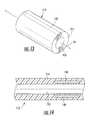
- FIG. 4is a perspective view of a flexible medical device for puncturing an atrial septum in the heart in an MRI environment, according to some embodiments of the present invention.
- FIG. 5is a plan view of the sheath of the device of FIG. 4 .
- FIG. 6is a plan view of the dilator of the device of FIG. 4 .
- FIG. 7is a perspective view of the needle of the device of FIG. 4 .
- FIG. 8is an enlarged partial perspective view of the distal end of the device of FIG. 4 .
- FIG. 9Ais an enlarged partial plan view of the distal end of the device of FIG. 4 .
- FIG. 9Bis an enlarged partial plan view of a distal end of a dilator that may be used with the device of FIG. 4 , according to other embodiments of the present invention.
- FIG. 10is a cross sectional view of the device of FIG. 9A , taken along lines 10 - 10 .
- FIG. 11is a cross sectional view of the device of FIG. 9A , taken along lines 11 - 11 .
- FIG. 12Ais an enlarged partial perspective view of the distal end of the sheath illustrated in FIG. 9A and illustrating a tracking member, according to some embodiments of the present invention.
- FIG. 12Bis an enlarged cross sectional view of the sheath of FIG. 12A taken along lines 12 B- 12 B.
- FIG. 13is an enlarged partial perspective view of the distal end of the sheath of the device of FIG. 4 and illustrating a tracking member, according to other embodiments of the present invention.
- FIG. 14is an enlarged partial cross sectional view of the distal end of the sheath of the device of FIG. 4 and illustrating a tracking member, according to other embodiments of the present invention.
- FIG. 15is an electrical schematic diagram of an RF tracking coil at the distal end of the dilator as illustrated in FIG. 9A and a corresponding coaxial cable connected thereto, according to some embodiments of the present invention.
- FIG. 16schematically illustrates two coaxial cables extending along a length of the dilator of the device of FIG. 4 and terminating at a connector housing at the dilator proximal end, according to some embodiments of the present invention.
- FIG. 17is an electrical schematic illustration of the electrical connections within the connector housing illustrated in FIG. 16 , according to some embodiments of the present invention.
- FIG. 18is an enlarged partial plan view of the distal end of a needle that can be utilized in the device of FIG. 4 , and illustrating a mating configuration of the needle tip portion and needle body, according to some embodiments of the present invention.
- FIG. 19is an enlarged partial plan view of the distal end of a needle that can be utilized in the device of FIG. 4 , and illustrating alternating sections of conductive and non-conductive material, according to some embodiments of the present invention.
- FIG. 20is an enlarged partial plan view of the distal end of a needle that can be utilized in the device of FIG. 4 , and illustrating telescoping segments, according to some embodiments of the present invention.
- FIG. 21is an enlarged partial plan view of the distal end portion of a needle that can be utilized in the device of FIG. 4 , and illustrating an RF tracking coil associated therewith, according to some embodiments of the present invention.
- FIG. 22is a perspective view of a guidewire that can be utilized with the device of FIG. 4 , according to some embodiments of the present invention.
- FIG. 23is an enlarged partial plan view of the distal end of the guidewire of FIG. 22 illustrating a pattern of tracking members, according to some embodiments of the present invention.
- FIG. 24is an enlarged cross sectional view of the tip portion of a needle that can be utilized in the device of FIG. 4 and illustrating a coating of material therearound, according to some embodiments of the present invention.
- FIGS. 25A-25Dare contemplated screen shots of exemplary interactive visualizations with a physical representation of an intrabody flexible medical device, such as the device of FIG. 4 , according to some embodiments of the present invention.
- FIG. 26is a schematic illustration of a display with two viewing windows, one showing an interactive visualization and the other showing at least one relevant near RT MRI image according to some embodiments of the present invention.
- FIG. 27is a contemplated screen shot of an exemplary visualization on a display and GUI controls that can be generated to facilitate an MRI guided procedure using the device of FIG. 4 , according to some embodiments of the present invention.
- FIGS. 28 and 29 A- 29 Gare exemplary screen shots illustrating navigational indicia that can be used to help guide and/or position an intrabody device, such as the septal puncture device of FIG. 4 , according to embodiments of the present invention.
- FIG. 30is a schematic illustration of an MRI-interventional suite according to some embodiments of the present invention.
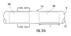
- FIG. 31Ais a partial side view of the sheath of the device of FIG. 4 including multiple RF shields in end-to-end spaced-apart relationship, according to some embodiments of the present invention.
- FIG. 31Bis a cross-sectional view of the sheath of FIG. 31A taken along line 31 B- 31 B.
- FIG. 31Cis a cross-sectional view of the sheath of FIG. 31A taken along line 31 C- 31 C.
- FIG. 32is a circuit diagram of an exemplary tracking coil tuning circuit according to some embodiments of the present invention.
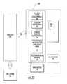
- FIG. 33is a schematic illustration of a data processing circuit or system according to embodiments of the present invention.
- spatially relative termssuch as “under”, “below”, “lower”, “over”, “upper” and the like, may be used herein for ease of description to describe one element or feature's relationship to another element(s) or feature(s) as illustrated in the figures. It will be understood that the spatially relative terms are intended to encompass different orientations of the device in use or operation in addition to the orientation depicted in the figures. For example, if the device in the figures is inverted, elements described as “under” or “beneath” other elements or features would then be oriented “over” the other elements or features. Thus, the exemplary term “under” can encompass both an orientation of “over” and “under”.
- the devicemay be otherwise oriented (rotated 90 degrees or at other orientations) and the spatially relative descriptors used herein interpreted accordingly.
- the terms “upwardly”, “downwardly”, “vertical”, “horizontal” and the likeare used herein for the purpose of explanation only unless specifically indicated otherwise.
- circuitrefers to an entirely software embodiment or an embodiment combining software and hardware aspects, features and/or components (including, for example, at least one processor and software associated therewith embedded therein and/or executable by and/or one or more Application Specific Integrated Circuits (ASICs), for programmatically directing and/or performing certain described actions or method steps).
- the circuitcan reside in one location or multiple locations, it may be integrated into one component or may be distributed, e.g., it may reside entirely in an MR Scanner control cabinet, partially in the MR Scanner control cabinet, totally in a separate component or system such as a clinician workstation but communicate with MR Scanner electronics and/or in an interface therebetween, in a remote processor and combinations thereof.
- MRIMagnetic Resonance Imaging system
- the operating componentse.g., RF amplifier, gradient amplifiers and processors that direct the pulse sequences and select the scan planes.
- Embodiments of the present inventioncan be utilized with any MRI Scanner including, but not limited to, GE Healthcare: Signa 1.5 T/3.0 T; Philips Medical Systems: Achieva 1.5 T/3.0 T; Integra 1.5 T; Siemens: MAGNETOM Avanto; MAGNETOM Espree; MAGNETOM Symphony; MAGNETOM Trio; and MAGNETOM Verio.
- pre-set scan planerefers to scan planes electronically (programmatically) defined for subsequent use by an MRI Scanner as being associated with a location of relevant anatomical tissue of a patient during a MRI guided therapeutic or diagnostic procedure.
- the pre-set scan planescan be defined based on a volumetric model or map of patient anatomical structure that is subsequently registered or aligned in 3-D imaging space and can be used to acquire near real-time MR image data of patient tissue.
- the actual pre-set scan planesare typically electronically defined after the model used to select a desired spatial location of a corresponding relevant scan plane is registered to the 3-D imaging space.
- tissue characterization maprefers to a rendered visualization or image of one or more selected parameters, conditions, or behaviors of cardiac tissue using MR image data
- the tissue characterization mapis a rendered partial or global (volumetric) anatomical map that shows at least one defined tissue characteristic of the heart in a manner that illustrates relative degrees or measures of that tissue characteristic(s), typically in different colors, opacities and/or intensities.
- the tissue characterization mapis to be contrasted with an electroanatomical tissue map which is based on sensed electrical activity of different regions of the heart rather than on MR image data.
- the visualizationscan use one or both types of volumetric maps (the term “map” is interchangeably used herein with the word “model”).
- the visualizationscan use one or both types of volumetric tissue maps, shown separately, overlaid on each other and/or integrated as a composite map.
- tissue data from an electroanatomical map and/or the tissue characteristic mapcan be selectively turned on and off with respect to a pre-acquired map/model of the patient's anatomical structure (e.g., Left Atrium).
- the actual visualizationcan be shown on a screen or display so that the map or anatomical structure is in a flat 2-D and/or in 2-D what appears to be 3-D volumetric images with data representing features or electrical output with different visual characteristics such as with differing intensity, opacity, color, texture and the like.
- a 4-D mapcan either illustrate a 3-D heart with movement (e.g., a beating heart and/or a heart with blood flow) or show additional information over a 3-D anatomic model of the contours of the heart or portions thereof.
- programmeans that the operation or step can be directed and/or carried out by a digital signal processor, computer program code and/or an Application Specific Integrated Circuit (ASIC).
- ASICApplication Specific Integrated Circuit
- electrotronicallymeans that the step or operation can be carried out in an automated manner using electronic components rather than manually or using merely mental steps.
- RF safemeans that a device and any conductive lead is configured to operate safely when exposed to RF signals, particularly RF signals associated with MRI systems, without inducing unplanned current that inadvertently unduly heats local tissue or interferes with the planned therapy.
- MRI visiblemeans that a device or portion thereof is visible, directly or indirectly, in an MRI image. The visibility may be indicated by the increased signal-to-noise ratio (SNR) of the MRI signal proximate the device or a lack of signal at the device.
- SNRsignal-to-noise ratio
- a devicecan act as an MRI receive antenna to collect signal from local tissue and/or the device actually generates MRI signal itself, such as via suitable medical grade hydro-based coatings, fluid (e.g., aqueous fluid) filled channels or lumens.
- MRI compatiblemeans that a component is safe for use in an MRI environment and as such is typically made of non-ferromagnetic MRI compatible material(s) suitable to reside and/or operate in a high magnetic field environment.
- high-magnetic fieldrefers to field strengths above about 0.5 T, typically above 1.0 T, and more typically between about 1.5 T and 10 T. Embodiments of the invention may be particularly suitable for 1.5 T and/or 3.0 T systems.
- the term “near real time”refers to both low latency and high frame rate. Latency is generally measured as the time from when an event occurs to display of the event (total processing time).
- the frame ratecan range from between about 100 fps (frames per second) to the imaging frame rate. In some embodiments, the tracking is updated at the imaging frame rate.
- the frame rateis typically between about 1 fps to about 20 fps, and in some embodiments, between about 3 fps to about 7 fps.
- a new imagecan be generated about every 1-7 s, depending on the sequence used.
- the low latency required to be considered “near real time”is generally less than or equal to about 1 second.
- the latency for tracking informationis about 0.01 s, and typically between about 0.25-0.5 s when interleaved with imaging data.
- visualizations with the location, orientation and/or configuration of a known intrabody devicecan be updated with low latency between about 1 fps to about 100 fps.
- visualizations using near real time MR image datacan be presented with a low latency, typically within between about 0.01 ms to less than about 1 second, and with a frame rate that is typically between about 1-20 fps.
- the systemcan use the tracking signal and image signal data to dynamically present anatomy and one or more intrabody devices in the visualization in near real-time.
- the tracking signal datais obtained and the associated spatial coordinates are determined while the MR image data is obtained and the resultant visualization(s) with the intrabody device (e.g., flexible catheter using the tracking coil data) and the near RT MR image(s) is generated.
- the intrabody devicee.g., flexible catheter using the tracking coil data
- tracking memberincludes all types of components that are visible in an MRI image including miniature RF tracking coils, passive markers, and receive antennas.
- a miniature RF tracking coilcan be connected to a channel of an MRI Scanner.
- the MR Scannercan be configured to operate to interleave the data acquisition of the tracking coils with the image data acquisition, as discussed further below.
- MRIhas several distinct advantages over X-ray imaging technology, such as: excellent soft-tissue contrast, the ability to define any tomographic plane, and the absence of ionizing radiation exposure.
- MRIoffers several specific advantages that make it especially well suited for guiding transseptal puncture procedures including: 1) near real-time interactive imaging, 2) direct visualization of critical endocardial anatomic landmarks, 3) direct high resolution imaging of the septum, including the fossa ovalis, 4) visualization of the needle tip-tissue interface, 5) the ability to actively track needle position in three-dimensional space, and 6) elimination of radiation exposure.
- Embodiments of the present inventioncan be configured to guide and/or place diagnostic or interventional devices in an MRI environment (e.g., interventional medical suite) to any desired internal region of a subject of interest, including, in some embodiments, to a cardiac location.
- the subjectcan be animal and/or human subjects.
- Some embodiments of the inventionprovide systems that can be used to ablate tissue for treating AFIB, and/or to deliver stem cells or other cardio-rebuilding cells or products into cardiac tissue, such as a heart wall, via a minimally invasive MRI guided procedure while the heart is beating (i.e., not requiring a non-beating heart with the patient on a heart-lung machine).
- the systemcan be configured so that the surgical space is the imaging space and the tracking is performed in the imaging space so that there is no requirement to employ a discrete tracking system that must then be registered to the imaging space.
- the trackingis carried out in the same 3-D imaging space but the flexible intrabody medical device is tracked independent of the imaging scan planes used to obtain the MR image data for generating images of local anatomy and is shown as a physical representation in the visualization.
- the systemcan be configured to work with robotic systems or non-robotic systems.
- FIG. 1illustrates an MRI interventional system 10 with a scanner 10 S and a flexible intrabody medical device 80 proximate target tissue 200 at a device-tissue interface 200 i .
- the system 10can be configured to electronically track the 3-D location of the device 80 in the body and identify and/or “know” the location of the tip portion 80 t of the device 80 (e.g., the dilator or needle tip) in a coordinate system associated with the 3-D imaging space.
- the device 80can include a plurality of spaced-apart tracking members 82 on a distal end portion thereof.
- the device 80can be a device configured to punch through atrial septums (e.g., the device 100 of FIG. 4 ).
- the tracking members 82can comprise miniature tracking coils, passive markers and/or a receive antenna.
- the tracking members 82include at least one miniature tracking coil 82 c that is connected to a channel 10 ch of an MRI Scanner 10 S ( FIG. 2 ).
- the MR Scanner 10 Scan be configured to operate to interleave the data acquisition of the tracking coils with the image data acquisition.
- the tracking datais acquired in a ‘tracking sequence block’ which takes about 10 msec (or less).
- the tracking sequence blockcan be executed between each acquisition of image data (the ‘imaging sequence block’). So the tracking coil coordinates can be updated immediately before each image acquisition and at the same rate.
- the tracking sequencecan give the coordinates of all tracking coils simultaneously. So, typically, the number of coils used to track a device has substantially no impact on the time required to track them.
- Embodiments of the present inventionprovide a new platform that can help facilitate clinical decisions during an MRI-guided procedure and can present real anatomical image data to the clinician in a visualization 200 v .
- the visualizations 200 v(e.g., as illustrated in FIGS. 25A-25D and 29 A- 29 G) can be dynamically generated as the intrabody device 80 moves in the body into and/or about a target location, as a user rotates, crops or otherwise alters a displayed visualization or view and/or during navigation with minimal latent time between serial MRI image data acquisitions, typically less than about 5 seconds, typically substantially continuously with a minimal latent time of about 1 second or less, such as between about 0.001 seconds and 1 second.
- the system 10can use the tracking signal(s) and image signal data to dynamically track the device 80 (which is typically a plurality of devices) and present visualizations of the anatomy and one or more intrabody devices 80 in near real-time.
- the term “physical representation”means that a device is not actually imaged but rather rendered with a physical form in the visualizations.
- the physical representationmay be of any form including, for example, a graphic with at least one geometric shape, icon and/or symbol.
- the physical representationmay be a virtual graphic substantial replica substantially corresponding to an actual shape and configuration of the actual physical appearance and/or configuration of the associated device (see, e.g., FIGS. 29A-29G ).
- the physical representationcan be electronically generated based on a priori knowledge of the dimensions and configuration of the device.
- the tip and each tracking coil on a distal end of a particular devicemay be shown in a geometric shape (the same or different shapes, e.g., an arrow for the tip and a sphere or block or other (typically 3-D) shape for tracking coils, each in its real location in the 3-D space and in its relative position on the device and each may be rendered with the same or a different color.
- the tip and each proximate tracking coilmay be shown in a different color.
- vasculaturerefers to a curvilinear pathway in the body, typically associated with a natural lumen such as vasculature.
- dynamic visualizationsrefers to a series of visualizations that show the movement of the device(s) in the body and can show a beating heart or movement based on respiratory cycle and the like.
- pre-acquiredmeans that the data used to generate the model or map of the actual patient anatomy was obtained prior to the start of an active therapeutic or diagnostic procedure and can include immediately prior to but during the same MRI session or at an earlier time than the procedure (typically days or weeks before).
- Some embodiments of the inventionprovide systems that can be used to facilitate ablation of tissue for treating AFIB, or to repair or replace cardiac valves, repair, flush or clean vasculature and/or place stents, and/or to deliver stem cells or other cardio-rebuilding cells or products into cardiac tissue, such as a heart wall, via a minimally invasive MRI guided procedure while the heart is beating (i.e., not requiring a non-beating heart with the patient on a heart-lung machine).
- the cardiac procedurescan be carried out from an inside of the heart or from an outside of the heart.
- the systemmay also be suitable for delivering a therapeutic agent or carrying out another treatment or diagnostic evaluation for any intrabody location, including, for example, the brain, gastrointestinal system, genourinary system, spine (central canal, the subarachnoid space or other region), vasculature or other intrabody locations. Additional discussion of exemplary target regions can be found at the end of this document.
- the system 10 and/or circuit 60 ccan calculate the position of the tip 80 t of the device 80 as well as the shape and orientation of the flexible device based on a priori information on the dimensions and behavior of the device 80 (e.g., for a steerable device, the amount of curvature expected when a certain pull wire extension or retraction exists, distance to tip from different coils 82 and the like).
- the circuit 60 ccan rapidly generate visualizations showing a physical representation of the location of a distal end portion of the device 80 with near RT MR images of the anatomy.
- the tracking signal datais obtained and the associated spatial coordinates are determined while a circuit 60 c in the MRI Scanner 10 S ( FIG. 2 ) and/or in communication with the Scanner 10 S obtains MR image data.
- the reverse operationcan also be used.
- the circuit 60 ccan then rapidly render the resultant visualization(s) 200 v (see, e.g., FIGS. 25A-25D ) with the flexible device(s) 80 shown with a physical representation based on spatial coordinates of the devices in the 3-D imaging space identified using the associated tracking coil data and the near RT MR image(s).
- the circuit 60 ccan be totally integrated into the MR Scanner 10 S (e.g., control cabinet), partially integrated into the MR Scanner 10 S or be separate from the MR Scanner 10 S but communicate therewith. If not totally integrated into the MR Scanner 10 S, the circuit 60 c may reside partially or totally in a workstation 60 ( FIG. 3 ) and/or in remote or other local processor(s) and/or ASIC.
- FIG. 3illustrates that a clinician workstation 60 can communicate with the MR Scanner 10 S via an interface 44 .
- the device 80 in the magnet roomcan connect to the MR Scanner 10 S via an interface box 86 which may optionally be integrated into the patch panel 250 .
- the system 10can include at least one (interactive) display 20 in communication with the circuit 60 c and/or the Scanner 10 S.
- the display 20can be configured to display the interactive visualizations 200 v (e.g., FIGS. 25A-25D ).
- the visualizations 200 vcan be dynamic showing the movement of the device 80 relative to the intrabody anatomical structure shown by the displayed near-real time MRI image.
- the system 10can include a user interface (UI) 25 , such as a graphical user interface (GUI) with several GUI controls 25 c ( FIG.
- UIuser interface
- GUIgraphical user interface
- the system 10can be configured to allow a user to select to show a map of patient vasculature and/or fibrous tissue based on pre-acquired image data (such as segmented MRA (Magnetic Resonance Angiography or other image slices) with the map or data therefrom being registered to and overlaid onto or incorporated into at least one of the models 200 M ( FIG.
- a clinicianin the visualization and can be selectively turned on and off by a user.
- This informationmay help a clinician select a treatment site or avoid a treatment site or otherwise affect clinical choices. For example, for cardiac use, if vasculature with a relatively large blood flow is shown in a target lesion space in cardiac tissue and/or if fibrous tissue is shown, a clinician may choose another spot or may ablate longer to form a transmural lesion. Further examples of display options will be discussed further below.
- the system/circuit 10 / 60 ccan employ interactive application of non-selective saturation to show the presence of a contrast agent in near real-time scanning.
- This optioncan help, for example, during image-guided catheter navigation to target tissue that borders scar regions. See, e.g., Dick et al., Real Time MRI enables targeted injection of labeled stem cells to the border of recent porcine myocardial infarction based on functional and tissue characteristics , Proc. Intl. Soc. Mag. Reson. Med. 11, p.
- FIG. 2illustrates that the device 80 can include at least one conductor 81 , such as a coaxial cable that connects a respective tracking coil 82 c to a channel 10 ch of the MR Scanner 10 S.
- the MR Scanner 10 Scan include at least 16 separate channels, and typically more channels but may operate with less as well.
- Each device 80can include between about 1-10 tracking coils, typically between about 1-4.
- the coils 82 c on a particular device 80can be arranged with different numbers of turns, different dimensional spacing between adjacent coils 82 c (where more than one coil is used) and/or other configurations.
- the circuit 60 ccan be configured to generate the device renderings based on tracking coil locations/positions relative to one another on a known device with a known shape and/or geometry or predictable or known changeable (deflectable) shape or form (e.g., deflectable end portion).
- the circuitcan identify or calculate the actual shape and orientation of the device for the renderings based on data from a CAD (computer aided design) model of the physical device.
- the circuitcan include data regarding known or predictable shape behavior based on forces applied to the device by the body or by internal or external components and/or based on the positions of the different tracking coils in 3-D image space and known relative (dimensional) spacings.
- the display 20can be provided in or associated with a clinician workstation 60 in communication with an MRI Scanner 10 .
- Other displaysmay be provided.
- the MRI Scanner 10 Stypically includes a magnet 15 in a shielded room and a control cabinet 11 (and other components) in a control room in communication with electronics in the magnet room.
- the MRI Scanner 10 Scan be any MRI Scanner as is well known to those of skill in the art.
- the tracking coils 82 ccan each include a tuning circuit that can help stabilize the tracking signal for faster system identification of spatial coordinates.
- FIG. 32illustrates an example of a tuning circuit 83 that may be particularly suitable for a tracking coil 82 c on an ablation catheter.
- CON 1connects the coaxial cable to the tracking coil 82 c on a distal end portion of the device 80 while J 1 connects to the MR Scanner channel 10 ch .
- the Scanner 10 Ssends a DC bias to the circuit 83 and turns U 1 diode “ON” to create an electrical short which creates a high impedance (open circuit) on the tracking coil to prevent current flow on the tracking coil and/or better tracking signal (stability).
- the tuning circuitcan be configured to have a 50 Ohm matching circuit (narrow band to Scanner frequency) to electrically connect the cable to the respective MR Scanner channel.
- the tracking coil datacan be transmitted to the MR Scanner receiver channel 10 ch .
- the C 1 and C 2 capacitorsare large DC blocking capacitors.
- C 4is optional but can allow for fine tuning (typically between about 2-12 picofarads) to account for variability (tolerance) in components. It is contemplated that other tuning circuits and/or tracking signal stabilizer configurations can be used.
- the tuning circuit 83can reside in the intrabody device 80 (such as in a handle or external portion), in a connector that connects the coil 82 c to the respective MRI scanner channel 10 ch , in the Scanner 10 S, in an interface box 86 ( FIG. 2 ), a patch panel 250 and/or the circuit 83 can be distributed among two or more of these or other components.
- each tracking coil 82 ccan be connected to a coaxial cable 81 having a length to the diode via a proximal circuit board (which can hold the tuning circuit and/or a decoupling/matching circuit) sufficient to define a defined odd harmonic/multiple of a quarter wavelength (lambda ( ⁇ )) at the operational frequency of the MRI Scanner 10 S, e.g., ⁇ /4, 3 ⁇ /4, 5 ⁇ /4, 7 ⁇ /4 at about 123.3 MHz for a 3.0 T MRI Scanner.
- This lengthmay also help stabilize the tracking signal for more precise and speedy localization.
- the tuned RF coilscan provide stable tracking signals for precise localization, typically within about 1 mm or less. Where a plurality (e.g., two closely spaced) of adjacent tracking coils are fixed on a substantially rigid material, the tuned RF tracking coils can provide a substantially constant spatial difference with respect to the corresponding tracking position signals.
- the tracking sequence used in the system 10can intentionally dephase signal perpendicular to the read-out direction to attenuate unwanted signal from 1) bulk objects and 2) regions sensed by other signal sensitive parts of the catheter which couple to the tracking coil (e.g. the coaxial cable along the catheter shaft). This tends to leave only a sharp peak indicating the position of the tracking coil.
- the tracking sequence blockcan include or consist of a plurality of (typically about three) repetitions of a small flip-angle excitation. Each repetition is designed to indicate the x, y or z component of the tracking coil coordinates in succession.
- Frequency encodingis used along the x-direction to obtain the x-coordinate, the y-direction for the y-coordinate, and the z-direction for the z-coordinate.
- the frequency encodingis in the x-direction, the other two directions (y and z) are not spatially encoded, producing projection (spatially integrated) signals in those directions from all excitation regions.
- the dephasing gradientattempts to attenuate unwanted signal included in these projections.
- a spoiler gradientcan be used to dephase any transverse signal remaining from the tracking before the imaging sequence block is executed.
- the imaging sequence blockobtains a portion, depending on the acceleration rate, of the data used to reconstruct an image of a single slice. If the acceleration rate is 1, then all of the data for an image is collected. If the acceleration rate is 2, then half is collected, etc. If multiple slices are activated, then each successive imaging block collects data for the next slice, in “round robin” fashion. If any saturation pulses are activated, these are executed after the tracking sequence block, immediately before the imaging sequence block.
- the device 100can be tracked and displayed in an MR system 10 similar to or the same as device 80 described above with respect to FIGS. 1-3 .
- the illustrated device 100includes an elongated sheath 112 , an elongated dilator 120 , and an elongated needle 130 .
- the needle 130is retracted in the dilator 120 .
- the sheath 112has opposite distal and proximal ends 112 a , 112 b , and a central lumen 113 ( FIGS. 5 , 8 ).
- the sheath wall 114is relatively thin.
- the diameter and length of the sheath 112may vary depending upon the subject in which the device 100 is being utilized.
- the sheath 112may have a size of between about 5 French and about 12 French (0.010′′-0.030′′).
- embodiments of the present inventionare not limited to any particular sheath size or length.
- the sheath 112comprises MRI compatible material, such as flexible polymeric material and/or combinations of polymeric and/or non-ferromagnetic materials. Various types of materials may be utilized, as well. Embodiments of the present invention are not limited to the use of any particular MRI-compatible material.
- a portion 112 c of the sheath adjacent the distal end 112 ahas a generally curved configuration, as illustrated ( FIG. 5 ), which generally corresponds with the curvature of the respective distal ends 120 a , 130 a of the dilator 120 and needle 130 , respectively, and which facilitates movement and positioning of the distal end 112 a of the sheath within a subject's heart.
- the distal end 112 a of the sheath 112includes at least one tracking member 140 ( FIG. 9A ).
- the tracking member 140may comprise MRI-visible material deposited or coated or otherwise placed on or into the outer surface of the sheath wall 114 .
- the tracking member 140may be a miniature tracking coil (e.g., tracking coil 82 c , FIG. 2 ).
- the tracking member 140may be a receive antenna.
- the sheath proximal end 112 bis connected to a hemostasis valve 118 ( FIG. 5 ) that is configured to seal around the dilator 120 and other devices that may be inserted through the sheath lumen 113 ( FIG. 8 ) and to prevent or reduce blood loss and/or the entry of air.
- the illustrated sheath 112 in FIG. 5also includes a tube 116 that is in fluid communication with the sheath lumen 113 .
- the tube 116includes opposite distal and proximal ends 116 a , 116 b .
- the tube distal end 116 ais connected to the hemostasis valve 118 and is in fluid communication with the sheath lumen 113 via the hemostasis valve 118 to allow the delivery and/or removal of fluids through and from the sheath 112 .
- the tube proximal end 116 bis connected to a valve or stopcock 119 for controlling the delivery of fluids through the tube 116 .
- Another hemostasis valve 118is in fluid communication with the stopcock 119 , as illustrated, and is configured to seal around a device inserted through the tube 116 .
- the dilator 120has opposite distal and proximal ends 120 a , 120 b , and a central lumen 121 ( FIGS. 6 , 8 ).
- the dilator wall 124is relatively thin.
- the diameter and length of the dilator 120may vary depending upon the subject in which the device 100 is being utilized. In some embodiments, the dilator 120 may have a size of between about 5 French and about 12 French (0.010′′-0.030′′). However, embodiments of the present invention are not limited to any particular dilator size or length.
- the dilator 120comprises MRI-compatible material, such as a flexible polymeric material. Various other types of MRI-compatible materials may be utilized. Embodiments of the present invention are not limited to the use of any particular MRI-compatible material.
- the dilator distal end 120 ahas a tapered configuration, as illustrated in FIGS. 6 , 9 A and 9 B.
- a portion 120 c of the dilator adjacent the distal end 120 ahas a generally curved configuration, as illustrated.
- the dilator distal end 120 atypically includes at least two tracking members 150 ( FIGS. 6 , 9 A, 9 B).
- FIG. 9Billustrates the distal end 120 a of a dilator 120 , according to other embodiments of the present invention, with a longer taper than that shown in FIG. 9A and with tracking coils 150 spaced further apart.
- the dilator proximal end 120 bincludes a Luer-lock fitting 122 that is configured to matingly engage with a mating fitting of another device. Luer-lock fittings are well known and need not be described further herein.
- the dilator 120is configured to be inserted within the sheath lumen 113 , as will be described below.
- the needle 130has a distal end 130 a , an opposite proximal end 130 b , and a central lumen 131 ( FIG. 8 ) extending therethrough from the proximal end 130 b to the distal end 130 a .
- the size and length of the needle 130may vary depending upon the subject in which the device 100 is being utilized. In some embodiments, the needle 130 may have a size of between about 5 French and about 12 French (0.010′′-0.030′′). However, embodiments of the present invention are not limited to any particular needle size or length.
- a portion 130 c of the needle 130 adjacent the distal end 130 ahas a generally curved configuration and is bendable, as illustrated in FIG. 7 .
- the needle proximal end 130 bincludes a Luer-lock fitting 122 that is configured to matingly engage with a mating fitting connected to a device.
- the needle proximal end 130 balso includes a stopcock 119 for controlling the delivery of fluids through the needle lumen 131 .
- the needle lumen 131can be flushed with a saline or other solution delivered via a pump or other delivery system through the Luer-lock fitting 122 at the needle proximal end 130 b.
- the needle proximal end 130 balso includes a handle 132 with a base dial 133 .
- the handle 132is configured to be gripped by a user and to facilitate insertion of the needle 130 into the dilator 120 , to facilitate extension of the needle 130 from the dilator distal end 120 a , and to facilitate puncturing the septal wall via the needle distal end 130 a.
- the base dial 133 attached to the handle 132includes a tapered end portion 132 a that serves as a directional indicator for the curvature of the needle distal end 130 a .
- the base dial 133is connected to the needle proximal end 130 b such that the tapered end portion 132 a points in the direction that needle portion 130 c is curved.
- the base dial tapered end portion 132 aallows a user to always know in which direction the needle curved portion 130 c is oriented. Other configurations/members that can indicate direction of the needle may also be utilized.
- a tip portion 130 t of the needlecan comprise material visible in MRI and is configured to be deformable.
- Exemplary MRI-visible materialincludes, but is not limited to, nickel, nickel-molybdenum alloys, nickel-titanium alloys, stainless steel, titanium, and combinations thereof.
- the main body 130 d of the needle 130i.e., the remaining portion of the needle 130 ) comprises MRI-compatible material, such as polyester or other polymeric materials. However, various other types of MRI-compatible materials may be utilized. Embodiments of the present invention are not limited to the use of any particular MRI-compatible material.
- Tip 130 tcan be bonded to the polymeric main body 130 d of the needle in any of various known ways of bonding metallic and polymeric materials together including, but not limited to, adhesive bonding, ultrasonic welding or other welding, mechanical coupling, etc.
- FIG. 18illustrates an exemplary embodiment wherein needle tip 130 t and the needle body 130 d have corresponding mating ends 130 x , 130 y that facilitate bonding therebetween and allow for a bendable tip 130 t.
- the needle tip 130 tmay have a length of about four centimeters (4 cm) or less. In other embodiments, the needle tip 130 t may have a length of greater than 4 cm. However, when the needle tip 130 t has a length greater than 4 cm and is metallic or conductive, the needle tip 130 t may be divided into physically separate sections of conductive and non-conductive material to prevent or reduce heating of the needle tip 130 t when exposed to RF energy.
- tip portion 130 tmay be formed of alternating sections of conductive 130 tc and non-conductive 130 td materials ( FIG. 19 ). In other embodiments, the needle tip portion 130 t can comprise multiple segments 130 t 1 , 130 t 2 , 130 t 3 ( FIG.
- MRI-visible materialarranged telescopically (i.e., multiple segments joined together, each subsequent segment having a reduced outer diameter compared to the previous segment).
- insulation between one or more segmentscan be utilized to reduce unwanted heating.
- it is desirable to limit heat generated in the presence of MRIso that the electrical length of the conductive material is less than or equal to one-quarter wavelength ( ⁇ 1 ⁇ 4 ⁇ ) (e.g., in a 3 T MRI scanner, this is ⁇ 4 cm for a “bare” metal needle) or an odd harmonic thereof.
- tip portion 130 thas a tapered configuration that terminates at sharp piercing tip (i.e., the needle distal end 130 a ) that is configured to puncture the septal wall.
- the piercing tipmay have a beveled configuration.
- the needle tip portion 130 tmay include a tracking member, as will be described below.
- the needle tip portion 130 thas an outer coating 130 p of material, as illustrated in FIG. 24 .
- Exemplary coating materialsmay include, but are not limited to, MRI-visible materials, conductive materials, non-conductive materials, polymeric materials, etc.
- the coating 130 pmay extend around the entire circumference of tip portion 130 t . However, in other embodiments, the coating 130 p may extend only partially around the circumference of the tip portion 130 t . In some embodiments, the coating 130 p may extend along the entire length of the tip portion 130 t . However, in other embodiments, the coating 130 p may only extend along a partial length of the tip portion 130 t.
- FIG. 8is an enlarged partial perspective view of the distal end 100 a of the device 100 of FIGS. 4-7 . Portions of the needle 130 and dilator 120 are positioned within the sheath 112 , and the needle tip 130 t is extended outwardly from the dilator distal end 120 a (i.e., in a puncture position).
- FIG. 9Ais an enlarged partial plan view of the distal end 100 a of the device 100 of FIGS. 4-7 .
- the distal end 112 a of the sheath 112includes a tracking member 140 in the form of a passive MRI marker.
- passive MRI markersare visible in MRI as they generate MRI image data signals, but use no wires or circuitry.
- the passive MRI marker 140can be formed from material that contains nuclei with their own distinct signal that is different from water or fat. Exemplary material includes, but is not limited to, fluorine-19 material, hydrogel, etc.
- the position of the passive MRI marker 140 and, thus, the distal end 112 a of the sheath 112can be determined within the body of a subject and relative to the 3-D coordinate system of an MRI scanner.
- the passive MRI marker 140can be a material that does not provide any signal (i.e., shows as a dark spot in an MR image).
- passive MRI marker 140is a band or coating of material extending circumferentially around the sheath 112 having a thickness T m of between about 0.0005 inches and about 0.010 inches, and having a width W m of between about 0.010 inches and about 0.50 inches.
- FIGS. 12A-12Billustrate this embodiment in more detail.
- FIG. 12Ais an enlarged partial perspective view of the sheath distal end 112 a .
- the passive MRI marker 140can be substantially flush with the surface of the sheath wall 114 and extends circumferentially therearound.
- Embodiments of the present inventionare not limited to the illustrated configuration of passive MRI marker 140 .
- Passive MRI marker 140can have other configurations and shapes, without limitation.
- passive MRI marker 140may be an elongated, non-ferromagnetic rod of material embedded within the sheath wall 114 and extending axially in a direction substantially parallel with the axis A s of the sheath lumen 113 .
- passive MRI marker 140may be embedded within the sheath wall 114 and extend circumferentially and elongately therearound.
- passive MRI marker 140may be a coating applied to the surface of the sheath wall 114 . Combinations of the above may also be utilized.
- the dilator distal end 120 aincludes a pair of active tracking members 150 in adjacent, spaced-apart relationship.
- active tracking members 150generate tracking signals due to the RF signal transmission of an MRI scanner. This includes tracking members that emit an RF signal, tracking members that transmit an RF signal to the MR scanner via a connection, and tracking members that generate their own magnetic or electrical field by application of electrical currents.
- the active tracking members 150are miniature RF tracking coils configured to be electrically connected to an MRI scanner channel (e.g., similar to tracking coil 82 c being connected to channel 10 ch in FIG. 2 ).
- the RF tracking coils 150are typically embedded within the dilator wall 123 .
- each RF tracking coil 150is connected to a respective coaxial cable 160 that may also be embedded within the dilator wall 123 ( FIGS. 9A , 10 , and 11 ) and extends longitudinally along the dilator 120 to an electrical connector interface 168 ( FIG. 16 ) within housing 170 at the dilator proximal end 120 b .
- Coaxial cables 160are typically constructed of a metallic inner conductor and a metallic sheath “coaxially” surrounding the inner conductor that serves as an outer conductor.
- a dielectric materialsurrounds the inner conductor and electrically insulates the inner conductor from the surrounding metallic sheath.
- RF tracking coils 150may be between about 2-16 turn solenoid coils, typically 2-10 turn solenoid coils. However, other coil configurations may be utilized in accordance with embodiments of the present invention. Each of the RF tracking coils 150 can have the same number of turns or a different number of turns. It is believed that an RF tracking coil 150 with between about 2-4 turns at 3.0 T provides a suitable signal for tracking purposes. A dephasing signal acquisition can be used to obtain the tracking signals as described above.
- the tip portion 130 t of the needle 130may also or alternately include an RF tracking coil 150 .
- an RF tracking coilbecause of its close proximity to the RF tracking coils 150 at the dilator distal end 120 a may provide increased SNR because of the cooperation of the RF coils 150 of the dilator 120 and needle tip 130 t during MRI. This close positioning of RF tracking coils may provide a greater SNR than possible with just the RF tracking coils 150 on the dilator distal end 120 a.
- FIG. 15is an electrical schematic diagram of an RF tracking coil 150 and corresponding coaxial cable 160 connected thereto.
- One end of the RF tracking coil 150is connected to the center conductor 162 of the coaxial cable 160
- the other end of the RF tracking coil 150is connected to the outer conductor 164 of the coaxial cable 160 .
- FIG. 16schematically illustrates two coaxial cables extending along the length of the dilator 120 and terminating at a connector housing 170 at the dilator distal end 120 b .
- Cabling 172is configured to electrically connect the coaxial cables 160 and RF tracking coils 150 to MRI circuitry 180 .
- FIG. 17is a schematic illustration of the electrical connections (labeled as connectors 1 - 8 ) within connector housing 170 .
- Connectors 1 and 2are associated with one coaxial cable 160 and RF tracking coil 150
- connectors 7 and 8are associated with the other coaxial cable 160 and RF tracking coil 150 .
- Connectors 3 and 4 and connectors 5 and 6are associated with the MRI scanner identification channels (e.g., channel 10 ch , FIG. 2 ) and are used to identify that the proper device or portion thereof is connected to the proper channel.
- this identification circuitrycommunicates an identification of the dilator 120 to the MRI circuitry 180 so that the MRI scanner recognizes that the dilator 120 and RF tracking coils 150 are present.
- embodiments of the present inventionare not limited to the illustrated circuitry associated with RF tracking coils 150 , as discussed above.
- the device 100is configured to allow for safe MRI operation so as to reduce the likelihood of undesired deposition of current or voltage in tissue.
- the device 100can include RF chokes such as a series of axially spaced apart Balun circuits or other suitable circuit configurations. See, e.g., U.S. Pat. No. 6,284,971, the contents of which are hereby incorporated by reference as if recited in full herein, for additional description of RF inhibiting coaxial cable that can inhibit RF induced current.
- the device 100can include one or more RF shields for reducing RF induced currents, as described below with respect to FIGS. 31A-31C .
- the RF coils 150 and coaxial cables 60 in the device 100can include a series of back and forth segments (e.g., it can turn on itself in a lengthwise direction a number of times along its length) and/or include high impedance circuits. See, e.g., U.S. patent application Ser. Nos. 11/417,594; 12/047,832; and 12/090,583, the contents of which are hereby incorporated by reference as if recited in full herein.
- the coaxial cables 160can be co-wound for a portion or all of a length of the dilator 120 .
- connector housing 170may not be located at the dilator proximal end 120 b .
- a cable associated with the above-described electronics of the dilator 120can extend from the dilator distal end 120 b and can be configured to directly connect to an interface associated with an MRI scanner, e.g., at the edge of a gantry associated with an MR scanner or with a grounding mat utilized with the MR scanner.
- an introducer tubeis inserted into the femoral vein via a percutaneous puncture.
- a guidewire G( FIG. 22 ) is inserted through the introducer tube and into the femoral vein.
- the guidewirecomprises non-metallic material to avoid heating issues when exposed to MRI.
- the guidewirehas an atraumatic tip on the distal end G d thereof that is configured to guide the guidewire through the femoral vein while avoiding perforation of the femoral vein.
- the atraumatic tipmay have a “J-shaped” configuration, as illustrated in FIG. 23 .
- the guidewireincludes one or more tracking members.
- tracking members 140may be positioned adjacent the distal tip G d of the guidewire G and along various other portions of the guidewire.
- the guidewireis routed, using MRI guidance, cranially toward the heart until it reaches the right atrium via the inferior vena cava.
- the tracking members 140are visible in MRI and allow the position of the guidewire distal end G d to be accurately determined.
- An exemplary length of the guidewireis about one hundred fifty centimeters (150 cm), although embodiments of the present invention are not limited to guidewires of this length.
- a shorter “introducer” guidewiree.g., about fifty centimeters (50 cm) in length, and comprising non-metallic material may initially be inserted through the introducer tube and into the femoral vein.
- This introducer guidewiremay have a similar configuration to the longer guidewire that is routed to the heart.
- the introducer guidewiremay have an atraumatic tip with a “J-shaped” tip, and may include multiple tracking members arranged in a pattern. This introducer guidewire is removed prior to the insertion of the guidewire that is routed into the heart.
- the sheath 112is routed over the guidewire G, through the skin puncture, through the wall of the femoral vein, and into the central lumen of the femoral vein.
- the dilator 120is inserted through the proximal end 112 b of the sheath 112 and routed through the sheath 112 , over the guidewire, and advanced to the right atrium.
- the guidewireis removed and the needle 130 is inserted through the proximal end 120 b of the dilator 120 and routed to the right atrium.
- the sheath 112 and dilator 120are routed over the guidewire together as a unit, rather than as separate steps. It is understood that the above described steps may vary depending on the physician performing the procedure.
- the sheath 112 and dilator 120are positioned, under MRI guidance, so that the distal end 112 a , 120 a of each is located at the desired location with respect to the atrial septum that divides the right atrium from the left atrium.
- the needle 130is next advanced through the distal end 120 a of the dilator 120 and punctures the atrial septum.
- the dilator 120is then advanced over the needle 130 until the distal end 120 a of the dilator resides within the left atrium.
- the sheath 112is then advanced into the left atrium.
- the dilator 120 and needle 130are removed from the sheath 112 leaving the sheath 112 in position in the left atrium and providing an access path into the heart for diagnostic and/or therapeutic procedures.
- examples of visualizations 200 v with a physical representation 80 R of the intrabody device 80e.g., the septal puncture device 100 of FIGS. 4-7
- a volumetric model 200 M of target anatomical structuree.g., a volumetric model 200 M of target anatomical structure
- MRInear real-time MRI image 200 MRI.
- device 80may represent the septal puncture device 100 of FIGS. 4-7
- the physical representation 80 Rmay be the physical representation of at least a distal end of one or more components of device 100 .
- the circuit 60 c /Scanner 10 Sis configured to present a 3-D volumetric model of at least a portion of the patient's heart 200 M in the visualization 200 v with the model registered to the 3-D imaging space along with a physical representation of at least the distal end portion of the at least one intrabody device 80 R in the imaging space.
- the visualizationscan be carried out to show the tracking coils in the physical representation of the distal end portion of the medical device in different colors using the identified location of the tracking coils and defined form factor and/or dimensional data regarding actual coil placement on the device.
- the circuit 60 ccan be configured to generate the visualizations 200 v with at least two visual reference planes 41 , 42 (shown with a third intersecting plane 43 ) that are typically oblique or orthogonal to each other and extend through at least a major portion of the visualization 200 v .
- the planes 41 , 42 (and 43 )can be transparent and/or translucent. They may be shown with different color perimeters that correspond to a respective two-dimensional image slice (which may be shown as thumbnails on the display also with a perimeter of similar or the same color).
- the planes 41 , 42can move relative to each other in the imaging space or may be locked together, in any case they can be configured to move relative to the model 200 M in the imaging space.
- a usercan rotate and zoom the visualization 200 v which automatically adjusts the visualization shown on the display.
- the flexible device 80is not required to be in any of the relevant anatomical scan planes used to obtain MR data for the at least one near RT MRI image 100 MRI in the visualization and the distal end portion 80 d of the flexible device 80 can take on a curvilinear shape and the tip 80 t can be steered or guided into different target positions.
- the circuit 60 c( FIG. 2 ) is configured to associate a tip location of the device 80 with an arrow 82 a and render the visualization so that each tracking coil 82 on the distal end portion 80 d has a shape 82 s with a color, with each tracking coil 82 having a respective different color from the other tracking coils, and with a line or spline 82 /connecting the tip 82 a and the coils 82 c and the line 82 l is able to flex, bend and move to reflect movement of the device 80 in the visualizations 200 v .
- the system/circuitcan be configured to display color-highlighted images from tracking coil channels and display them with the images in the 3D rendering of the physical representation.
- FIG. 26illustrates that the system 10 ( FIG. 1 ) can be configured to show both the interactive visualization 200 v in one viewing window 20 w 1 and an MRI image 200 MRI alone in a second viewing window 20 w 2 .
- the MRI image 200 MRI in the second window 20 w 2is typically associated with the target anatomy location (identified by a user) in the interactive visualization 200 v in the first viewing window 20 w 1 .
- the display 20can have a UI 25 configured to allow a physician or other clinician to select whether to show near real time MR images of target tissue 200 MRI either with a model 200 M of the target anatomical structure (e.g., heart or access path thereto) and/or in a separate viewing window ( FIG. 26 ).
- the circuit 60is in communication with at least one display 20 with the UI 25 .
- the UI 25can be configured to allow a user to alter the displayed visualization (fade) to include only a near RT image of the anatomy, to include the near RT image of the anatomy and the registered model of the heart, or to include only the registered model, see, e.g., FIG. 27 showing both types of images in the visualization 200 v .
- the UI 25can be an on off selection of these options or may “fade” from one viewing option to another.
- a virtual sliding GUI control 25 callows a user to change what is shown ((near) RTMRI 100 MRI to only the Model 100 M).
- the circuit 60 ccan also be configured to generate images showing the device location in MR image space.
- the UI 25can also be configured to allow a user to fade the renderings of the device 80 in and out of the visualizations with actual images of the device and tracking coils to confirm location or for additional visual input.
- the devicemay include other fiducial markers (e.g., a passive marker or an active marker such as receive antenna) for facilitating the visual recognition in the MR image.
- the UI 25typically includes multiple GUI controls 25 c that can include a touch screen input control to allow a clinician/physician to select a region of interest in the map 200 M by placing a cursor or by touching the screen at a region of interest. This can cause the system to obtain real time MR image data of that region and provide the associated image on the display and/or define scan planes (which may be preset scan planes) at that location in space.
- GUI controls 25 ccan include a touch screen input control to allow a clinician/physician to select a region of interest in the map 200 M by placing a cursor or by touching the screen at a region of interest. This can cause the system to obtain real time MR image data of that region and provide the associated image on the display and/or define scan planes (which may be preset scan planes) at that location in space.
- FIG. 28illustrates that the system 10 ( FIG. 1 ) can illustrate the location of the treatment device 80 with additional visual indicators and a “target” mark for help in navigation to the site.
- FIGS. 29A-29Gillustrate side by side windows displaying visualizations 200 v of local tissue rendered by system 10 ( FIG. 1 ) in axial and en face views.
- a physical representation 100 R of the septal puncture device 100(including physical representations 120 R and 130 R of the dilator 120 and needle 130 ) is rendered in the left window, along with a rendering of the target location T L for puncturing a septal wall.
- the relative location of the target location T L and the actual location A L of the distal end 100 a of the device 100are rendered.
- FIGS. 29A-29Cillustrate movement of the device 100 closer to the target location T L
- FIG. 29Dillustrates the actual location A L of distal end portion 100 a of the device 100 at the target location T L .
- the dilator distal end 120 a of the device 100is pushing against the septal wall tissue SW at the target location T L .
- the septal wall tissue SWmay be tented to show that it is being pushed on.
- the needle 130 of the device 100punctures the septal wall tissue SW.
- 130 Ris the physical representation of the needle 130 .
- a dyemay be injected into the left atrium to facilitate MR visibility of the tissue associated therewith.
- the dilator distal end 120 ais moved through the septal wall tissue SW into the left atrium of the heart.
- the device 100can be visualized using a different pulse sequence from that used in a high-resolution ablation mode, such as, for example, an RT MRI sequence using GRE or SSFP (e.g., TrueFISP) pulse sequence with about 5.5 fps), the tracking coils 150 can be used for spatial orientation and positioning.
- Typical scan parameters for (near) real-timeinclude: echo time (TE) 1.5 ms, repetition time (TR) 3.5 ms, flip angle 12 degrees, slice thickness 5 mm, resolution 1.8 mm ⁇ 2.4 mm, parallel imaging with reduction factor (R) of 2.
- a pulse sequence at the associated scan planecan be used to generate high resolution visualization of the dilator distal end 120 a and (myocardial) tissue interface.
- a T1-weighted 3D FLASH sequenceT1w FLASH
- Myocardial or other target tissue images during ablation or other therapycan be acquired using an Inner Volume Acquisition (IVA) dark-blood prepared T2-weighted HASTE (T2w HASTE) or dark-blood prepared Turbo Spin Echo (TSE) sequence.
- IVAInner Volume Acquisition
- T2w HASTEdark-blood prepared T2-weighted HASTE
- TSEdark-blood prepared Turbo Spin Echo
- Typical heart beat rates and free breathingcan present imaging challenges.
- (near) RT navigation imaging slicese.g., GRE pulse sequence at 5.5 fps
- high-resolution tissue interface slicese.g., T1w FLASH
- slices acquired with different sequencescan be interlaced to provide an interactive environment for device 100 visualization and lesion delivery
- a GUIcan allow a user to toggle between these views or can alternate the views based on these image slices or navigation versus ablation or interventional modes/views.
- FIG. 30illustrates one particular embodiments using a cardiac MRI Interventional suite 19 with an integrated cable management system that connects multiple patient connected leads that remain in position even when a patient is translated in or out of a magnet bore on the gantry 16 (the magnet can be an open face or closed magnet configuration) to allow a clinician direct access to a patient.
- the other ends of the leadsconnect to power sources, monitors and/or controls located remote from the patient (typically in the control room not the magnet room). As shown in FIG.
- the MRI interventional suite 19can include an IV pole 240 (typically attached to the scanner table/gantry 16 ) and a connection block 250 of cables 200 n that are routed through a ceiling (e.g., they extend up, through and above a ceiling) (where “n” is typically between about 1-400, typically between about 5-100), that connect to patch bay 235 and/or 237 .
- Cabling 210 n for anesthesia cart 260can also be routed through the ceiling (where n is typically between about 1-400, typically between about 5-100).
- the cabling 200 n , 210 nextends through the ceiling between the rooms 10 a , 10 b and can connect to the remote devices 500 through a patch panel 250 .
- foot pedal cabling 220 ncan extend through a floor trough to the patch panel/second room 10 b as well (where “n” is typically between about 1-100 cables).
- nis typically between about 1-100 cables.
- the cablesmay also alternately be routed under, on or over the floor, suspended on walls, employ wireless connections and the like (and combinations of same).
- the system 10can include a monitoring circuit that can automatically detect which devices are connected to the patient patch bay. One way this can be achieved is by using ID resistors in the patch bay and/or interface as well as in various devices that connect thereto.
- the MRI scanner computer or processor or the clinician workstation module or processorcan monitor resistors via connections CON 1 , CON 2 and CON 3 .
- the devices 80FIG. 1
- the devices 80can have built-in resistors that modify the resistance by lines that connect to CON 1 , CON 2 and CON 3 . Variation in resistance values helps the monitor which device is connected. Once that determination is made the scanner may automatically load special acquisition parameters, display parameters and update the progress of the procedure to display on the display 20 such as at workstation 60 ( FIG. 3 ), for example.
- MR Scanner 10 Scan be provided via low pass filters inside and outside the MRI suite.
- components in the MRI Suitecan be connected to external components using a waveguide built into the RF shield that encloses the MRI suite.
- the ablation catheter 80can be connected to an appropriate energy source, such as, for example, a Stockert 70 RF generator (Biosense Webster, Diamond Bar, Calif., USA) with MR compatible interface circuits configured for 3 T magnetic fields (where a 3 T system is used).
- the systemcan comprise an EP Suite with a Siemens Verio system (Siemens Healthcare, Er Weg, Germany) or other suitable scanner as well as suitable external imaging coils, such as spine and/or body array coils as is known to those of skill in the art.
- Embodiments of the present inventionmay be utilized in conjunction with navigation and mapping software features.
- current and/or future versions of devices and systems described hereinmay include features with adaptive projection navigation and/or 3-D volumetric mapping technology, the latter may include aspects associated with U.S. patent application Ser. No. 10/076,882, which is incorporated herein by reference in its entirety.
- the sheath 112 of the septal puncture device 100 of FIGS. 4-7may include a plurality of RF shields 300 coaxially disposed within the wall W of the sheath 112 in end-to-end spaced-apart relationship.
- the RF shields 300are configured to impede RF coupling along the dilator 120 and/or needle 130 inserted within the sheath 112 when exposed to an MRI environment.
- a pair of RF shields 300are illustrated in FIG. 31A , it is understood that many additional RF shields 300 may be coaxially disposed within the elongated sheath wall W in end-to-end spaced-apart relationship. Only two RF shields 300 are shown for ease of illustration.
- each RF shield 300includes an elongated inner tubular conductor 302 having opposite end portions 302 a , 302 b , an elongated dielectric layer 304 that coaxially surrounds the inner conductor 302 , and an elongated outer tubular conductor 306 that coaxially surrounds the dielectric layer 304 and has opposite end portions 306 a , 306 b .
- the inner and outer tubular conductors 302 , 306are electrically connected to each other at only one of the end portions. The opposite respective end portions are electrically isolated.
- the inner and outer tubular conductors 302 , 306are electrically connected to each other via jumper wires 310 at adjacent end portions 302 b , 306 b ( FIG. 31C ).
- the inner and outer conductorscan be formed as thin-film foil layers of conductive material on opposite sides of a thin film insulator (e.g., a laminated, thin flexible body).
- a thin film insulatore.g., a laminated, thin flexible body
- the RF shields 300are spaced-apart sufficiently to allow articulation of the sheath 112 and without any stiff points. In some embodiments, adjacent RF shields 300 may be spaced-apart between about 0.1 inches and about 1.0 inches.
- each RF shield 300serves as a quarter-wave resonant choke that forms an effective parallel resonance circuit at a frequency of interest and/or generates high impedance at the inner shield at the location not shorted.
- Each RF shield 300impedes the formation of resonating RF waves along conductive members, such as electrical leads and, thus, the transmission of unwanted RF energy along the dilator 120 and/or needle 130 at such frequency.
- Each of the illustrated RF shields 300can be tuned to a particular frequency by adjusting the length L of the RF shield 300 and/or the thickness of the dielectric layer 304 .
- the length L of RF shield 300is about twenty inches (20′′) or less.
- the RF shield 300is not limited to a particular length.
- the systemcan be used for other anatomical regions and deliver or apply other therapies as well as for diagnostic procedures.
- the esophagus and anatomy near the esophaguse.g., the aorta, coronary arteries, mediastinum, the hepaticobiliary system or the pancreas in order to yield anatomic information about the structures in those areas, “pancreaticohepaticobiliary” structures (collectively the structures of the liver, gallbladder, bile ducts and pancreas), the tracheobronchopulmonary structure (structures including the lungs and the tracheobronchial tree), the nasopharynx system (e.g., a device introduced transnasally may be adapted for evaluating the arterial circle of Willis and related vascular structures for abnormalities, for example congenital or other aneurysms), the proximal aerodigestive system or the
- the systems and methods of the present inventionmay be particularly useful in those lesions whose extent is not readily diagnosed, such as basal cell carcinomas. These lesions may follow nerves into the orbit or into the intracranial area, extensions not evident with traditional imaging modalities to the surgeon undertaking the resection to provide real time information to the resecting surgeon or the surgeon performing a biopsy as to the likely areas of lymph node invasion.
- the systemscan be used in the “head and neck” which refers collectively to those structures of the ear, nose and throat and proximal aerodigestive system as described above, traditionally falling within the province of otorhinolaryngology.
- the term “head and neck,” as used herein,will further include those structures of the neck such as the thyroid, the parathyroid, the parotid and the cervical lymph nodes, and will include also the extracranial portions of the cranial nerves, including but not limited to the facial nerve, this latter nerve being included from its entry into the internal auditory meatus outward.
- head and neckwill also include those structures of the orbit or of the globe, including the oculomotor muscles and nerves, lacrimal glands and adnexal structures.
- head and neckwill further include those intracranial structures in proximity to the aforesaid head and neck structures.
- These intracranial structuresmay include, as examples, the pituitary gland, the pineal gland, the nuclei of various cranial nerves, the intracranial extensions of the cranial nerves, the cerebellopontine angle, the arterial circle of Willis and associated vascular structures, the dura, and the meninges.
- the systemscan be used in the genourinary system, such as the urethra, prostate, bladder, cervix, uterus, and anatomies in proximity thereto.
- the term “genitourinary”shall include those structures of the urinary tract, the male genital system and the female genital system.
- the urinary tract structuresinclude the urethra, the bladder, the ureters, the kidney and related neural, vascular, lymphatic and adnexal structures.
- the male genital tractincludes the prostate, the seminal vesicles, the testicles, the epididymis and related neural, vascular, lymphatic, ductal and adnexal structures.
- the female genital tractincludes the vagina, the cervix, the non-gravid and gravid uterus, the fallopian tubes, the ovaries, the ova, the fertilized egg, the embryo and the fetus.
- the term “genitourinary”further refers to those pelvic structures that surround or support the above-mentioned structures, such as the paraurethral tissues, the urogenital diaphragm or the musculature of the pelvic floor.
- the devicescan be configured for transurethral placement for evaluation and treatment of female urinary incontinence or bleeding and may use high resolution images of the local tissue, e.g., different layers of the paraurethral tissues.
- the devicesmay also be configured for placement in the genitourinary system such as into the ureter or renal pelvis, urinary tract, or transvaginal use in analysis of the vagina and anatomies in proximity thereto.
- transvaginal or transcervical endouterine placementmay be useful in the diagnosis of neoplasia, in the diagnosis and treatment of endometriosis and in the evaluation of infertility or diagnosis, treatment of pelvic disorders resulting in pelvic pain syndromes, evaluation/treatment of cervical and uterine malignancies and to determine their stages, obstetric use such as permitting anatomic evaluation of mother and fetus.
- the systemscan be used for evaluating and/or treating the rectum or colon, typically by the transrectal route that can be inserted through the anus to a level within the rectum, sigmoid or descending colon where the designated anatomy can be visualized.
- this approachmay be used to delineate the anatomy of the prostate gland, and may further guide the biopsy or the extirpation of lesions undertaken transrectally or transurethrally.
- the systems and methods of the present inventionmay be used for the evaluation, diagnosis or treatment of a structure in the gastrointestinal system, or for the evaluation, diagnosis or treatment of a region of the gastrointestinal anatomy.
- gastrointestinalshall include structures of the digestive system including the esophagus, the stomach, the duodenum, jejunum and ileum (small intestine), the appendix and the colon.
- gastrointestinal anatomyshall refer to the structures of the gastrointestinal system as well as the surrounding supporting structures such as the mesentery and the enclosing structures such as the peritoneum, the diaphragm and the retroperitoneum.
- disorders of the gastrointestinal systemare well-known in the medical arts, as are disorders of the gastrointestinal anatomy.
- the intrabody devicemay be passed into the stomach.
- the systems and methods of the present inventionmay be used for the evaluation, diagnosis and treatment of the vascular system.
- the vascular systemis understood to include the blood vessels of the body, both arterial and venous.
- the vascular systemincludes both normal and abnormal blood vessels, named and unnamed vessels, and neovascularization. Access to the vascular system takes place using techniques familiar to practitioners of ordinary skill in the art.
- the present inventionmay be used in blood vessels of all size and the intrabody devices may be dimensionally adapted to enter smaller caliber vessels, such as those comprising the distal coronary circulation, the intracranial circulation, the circulation of the distal extremities or the distal circulation of the abdominal viscera.
- positioning a device within the vascular systemmay be useful for evaluating, diagnosing and treating conditions in structures adjacent to or in proximity to the particular vessel within which the device is situated.
- Such structuresare termed “perivascular structures.”
- a device placed within a coronary arterymay provide information about the vessel itself and about the myocardium that is perfused by the vessel or that is adjacent to the vessel.
- a device thus positionedmay be able to guide therapeutic interventions directed to the myocardial tissue, and may also be able to guide endovascular or extravascular manipulations directed to the vessel itself. It will be readily appreciated by those of ordinary skill in the art that a number of other applications exist or may be discovered with no more than routine experimentation using the systems and methods of the present invention within the vascular system.
- access to anatomic structures using the systems, devices modified to fit the intended purpose and anatomy, and methods of the present inventionmay be provided via naturally occurring anatomic orifices or lumens, as indicated in the examples above. It is further understood, however, that access to anatomic structures using these systems and methods may be additionally provided using temporary or permanent orifices that have been created medically.
- methods and systemsmay cooperate with robotic driven systems rather than manual systems.
- Some embodiments of the present inventionmay take the form of an entirely software embodiment or an embodiment combining software and hardware aspects, all generally referred to herein as a “circuit” or “module.”
- the present inventionmay take the form of a computer program product on a computer-usable storage medium having computer-usable program code embodied in the medium. Any suitable computer readable medium may be utilized including hard disks, CD-ROMs, optical storage devices, a transmission media such as those supporting the Internet or an intranet, or magnetic storage devices.
- Some circuits, modules or routinesmay be written in assembly language or even micro-code to enhance performance and/or memory usage.
- program modulesmay also be implemented using discrete hardware components, one or more application specific integrated circuits (ASICs), or a programmed digital signal processor or microcontroller.
- ASICsapplication specific integrated circuits
- Embodiments of the present inventionare not limited to a particular programming language.
- Computer program code for carrying out operations of data processing systems, method steps or actions, modules or circuits (or portions thereof) discussed hereinmay be written in a high-level programming language, such as Python, Java, AJAX (Asynchronous JavaScript), C, and/or C++, for development convenience.
- computer program code for carrying out operations of exemplary embodimentsmay also be written in other programming languages, such as, but not limited to, interpreted languages.
- Some modules or routinesmay be written in assembly language or even micro-code to enhance performance and/or memory usage.
- embodimentsare not limited to a particular programming language.
- any or all of the program modulesmay also be implemented using discrete hardware components, one or more application specific integrated circuits (ASICs), or a programmed digital signal processor or microcontroller.
- the program codemay execute entirely on one (e.g., a workstation computer or a Scanner's computer), partly on one computer, as a stand-alone software package, partly on the workstation's computer or Scanner's computer and partly on another computer, local and/or remote or entirely on the other local or remote computer.
- the other local or remote computermay be connected to the user's computer through a local area network (LAN) or a wide area network (WAN), or the connection may be made to an external computer (for example, through the Internet using an Internet Service Provider).
- LANlocal area network
- WANwide area network
- Internet Service Providerfor example, AT&T, MCI, Sprint, EarthLink, MSN, GTE, etc.
- These computer program instructionsmay also be stored in a computer-readable memory that can direct a computer or other programmable data processing apparatus to function in a particular manner, such that the instructions stored in the computer-readable memory produce an article of manufacture including instruction means which implement the function/act specified in the flowchart and/or block diagram block or blocks.
- the computer program instructionsmay also be loaded onto a computer or other programmable data processing apparatus to cause a series of operational steps to be performed on the computer or other programmable apparatus to produce a computer implemented process such that the instructions which execute on the computer or other programmable apparatus provide steps for implementing some or all of the functions/acts specified in the flowchart and/or block diagram block or blocks.
- each block in the flow charts or block diagramsrepresents a module, segment, or portion of code, which comprises one or more executable instructions for implementing the specified logical function(s).
- the functions noted in the blocksmay occur out of the order noted in the figures. For example, two blocks shown in succession may in fact be executed substantially concurrently or the blocks may sometimes be executed in the reverse order or two or more blocks may be combined, depending upon the functionality involved.
- the workstation 60 and/or interface 44 , 84 , or patch baymay also include a decoupling/tuning circuit that allows the system to cooperate with an MRI scanner 10 S and filters and the like. See, e.g., U.S. Pat. Nos. 6,701,176; 6,904,307 and U.S. Patent Application Publication No. 2003/0050557, the contents of which are hereby incorporated by reference as if recited in full herein.
- FIG. 33is a schematic illustration of a circuit or data processing system that can be used with the system 10 ( FIG. 1 ).
- the circuits and/or data processing systems 290may be incorporated in a digital signal processor in any suitable device or devices.
- the processor 410communicates with and/or is integral with an MRI scanner 10 S and with memory 414 via an address/data bus 448 .
- the processor 410can be any commercially available or custom microprocessor.
- the memory 414is representative of the overall hierarchy of memory devices containing the software and data used to implement the functionality of the data processing system.
- the memory 414can include, but is not limited to, the following types of devices: cache, ROM, PROM, EPROM, EEPROM, flash memory, SRAM, and DRAM.
- FIG. 33illustrates that the memory 414 may include several categories of software and data used in the data processing system: the operating system 449 ; the application programs 454 ; the input/output (I/O) device drivers 458 ; and data 456 .
- the data 456can also include device (ablation catheter) dimensions (e.g., distance of a tracking coil to the tip) and patient-specific image data 455 .
- FIG. 33illustrates that the memory 414 may include several categories of software and data used in the data processing system: the operating system 449 ; the application programs 454 ; the input/output
- the application programs 454can include a Tracking Coil Location Identification Calculation Module 450 , a Visualization Rendering Module 452 , an Interactive Visualization (and UI) Module 453 , a Tissue Characterization Map Module 456 , and a Pre-Set Scan Plane to Target Ablation Site Module 454 , a and a UI Interface Module 453 .
- the operating systems 449may be any operating system suitable for use with a data processing system, such as OS/2, AIX, or z/OS from International Business Machines Corporation, Armonk, N.Y., Windows CE, Windows NT, Windows95, Windows98, Windows2000, WindowsXP, Windows Visa, Windows7, Windows CE or other Windows versions from Microsoft Corporation, Redmond, Wash., Palm OS, Symbian OS, Cisco IOS, VxWorks, Unix or Linux, Mac OS from Apple Computer, LabView, or proprietary operating systems.
- VxWorkswhich can run on the Scanner's sequence generator for precise control of pulse sequence waveform timings.
- the I/O device drivers 458typically include software routines accessed through the operating system 449 by the application programs 454 to communicate with devices such as I/O data port(s), data storage 456 and certain memory 414 components.
- the application programs 454are illustrative of the programs that implement the various features of the data processing system and can include at least one application, which supports operations according to embodiments of the present invention.
- the data 456represents the static and dynamic data used by the application programs 454 , the operating system 449 , the I/O device drivers 458 , and other software programs that may reside in the memory 414 .
- Modules 450 , 452 , 453 , 454 , 456being application programs in FIG. 33
- the Modules and/ormay also be incorporated into the operating system 449 , the I/O device drivers 458 or other such logical division of the data processing system.
- the present inventionshould not be construed as limited to the configuration of FIG. 33 which is intended to encompass any configuration capable of carrying out the operations described herein.
- Modules 450 , 452 , 453 , 454 , 456can communicate with or be incorporated totally or partially in other components, such as separate or a single processor, an MRI scanner 10 S or workstation 60 .
- the I/O data portcan be used to transfer information between the data processing system, the workstation, the MRI scanner, and another computer system or a network (e.g., the Internet) or to other devices controlled by the processor.
- These componentsmay be conventional components such as those used in many conventional data processing systems, which may be configured in accordance with the present invention to operate as described herein.
Landscapes
- Health & Medical Sciences (AREA)
- Life Sciences & Earth Sciences (AREA)
- Engineering & Computer Science (AREA)
- General Health & Medical Sciences (AREA)
- Surgery (AREA)
- Physics & Mathematics (AREA)
- Public Health (AREA)
- Heart & Thoracic Surgery (AREA)
- Animal Behavior & Ethology (AREA)
- Biomedical Technology (AREA)
- Veterinary Medicine (AREA)
- Medical Informatics (AREA)
- Molecular Biology (AREA)
- Pathology (AREA)
- Biophysics (AREA)
- Nuclear Medicine, Radiotherapy & Molecular Imaging (AREA)
- Radiology & Medical Imaging (AREA)
- Vascular Medicine (AREA)
- Anesthesiology (AREA)
- Hematology (AREA)
- Condensed Matter Physics & Semiconductors (AREA)
- General Physics & Mathematics (AREA)
- Immunology (AREA)
- Robotics (AREA)
- Cardiology (AREA)
- Pulmonology (AREA)
- Otolaryngology (AREA)
- Human Computer Interaction (AREA)
- High Energy & Nuclear Physics (AREA)
- Endocrinology (AREA)
- Electromagnetism (AREA)
- Physiology (AREA)
- Magnetic Resonance Imaging Apparatus (AREA)
- Surgical Instruments (AREA)
- Media Introduction/Drainage Providing Device (AREA)
Abstract
Description
Claims (19)
Priority Applications (1)
| Application Number | Priority Date | Filing Date | Title |
|---|---|---|---|
| US13/723,612US8768433B2 (en) | 2009-06-16 | 2012-12-21 | MRI-guided devices and MRI-guided interventional systems that can track and generate dynamic visualizations of the devices in near real time |
Applications Claiming Priority (5)
| Application Number | Priority Date | Filing Date | Title |
|---|---|---|---|
| US18732309P | 2009-06-16 | 2009-06-16 | |
| US21963809P | 2009-06-23 | 2009-06-23 | |
| US26110309P | 2009-11-13 | 2009-11-13 | |
| US12/816,757US8396532B2 (en) | 2009-06-16 | 2010-06-16 | MRI-guided devices and MRI-guided interventional systems that can track and generate dynamic visualizations of the devices in near real time |
| US13/723,612US8768433B2 (en) | 2009-06-16 | 2012-12-21 | MRI-guided devices and MRI-guided interventional systems that can track and generate dynamic visualizations of the devices in near real time |
Related Parent Applications (1)
| Application Number | Title | Priority Date | Filing Date |
|---|---|---|---|
| US12/816,757ContinuationUS8396532B2 (en) | 2009-06-16 | 2010-06-16 | MRI-guided devices and MRI-guided interventional systems that can track and generate dynamic visualizations of the devices in near real time |
Publications (2)
| Publication Number | Publication Date |
|---|---|
| US20130116543A1 US20130116543A1 (en) | 2013-05-09 |
| US8768433B2true US8768433B2 (en) | 2014-07-01 |
Family
ID=43307014
Family Applications (5)
| Application Number | Title | Priority Date | Filing Date |
|---|---|---|---|
| US12/816,803Expired - Fee RelatedUS8369930B2 (en) | 2009-06-16 | 2010-06-16 | MRI-guided devices and MRI-guided interventional systems that can track and generate dynamic visualizations of the devices in near real time |
| US12/816,757Expired - Fee RelatedUS8396532B2 (en) | 2009-06-16 | 2010-06-16 | MRI-guided devices and MRI-guided interventional systems that can track and generate dynamic visualizations of the devices in near real time |
| US13/723,612ActiveUS8768433B2 (en) | 2009-06-16 | 2012-12-21 | MRI-guided devices and MRI-guided interventional systems that can track and generate dynamic visualizations of the devices in near real time |
| US13/738,621ActiveUS8886288B2 (en) | 2009-06-16 | 2013-01-10 | MRI-guided devices and MRI-guided interventional systems that can track and generate dynamic visualizations of the devices in near real time |
| US13/749,351ActiveUS8825133B2 (en) | 2009-06-16 | 2013-01-24 | MRI-guided catheters |
Family Applications Before (2)
| Application Number | Title | Priority Date | Filing Date |
|---|---|---|---|
| US12/816,803Expired - Fee RelatedUS8369930B2 (en) | 2009-06-16 | 2010-06-16 | MRI-guided devices and MRI-guided interventional systems that can track and generate dynamic visualizations of the devices in near real time |
| US12/816,757Expired - Fee RelatedUS8396532B2 (en) | 2009-06-16 | 2010-06-16 | MRI-guided devices and MRI-guided interventional systems that can track and generate dynamic visualizations of the devices in near real time |
Family Applications After (2)
| Application Number | Title | Priority Date | Filing Date |
|---|---|---|---|
| US13/738,621ActiveUS8886288B2 (en) | 2009-06-16 | 2013-01-10 | MRI-guided devices and MRI-guided interventional systems that can track and generate dynamic visualizations of the devices in near real time |
| US13/749,351ActiveUS8825133B2 (en) | 2009-06-16 | 2013-01-24 | MRI-guided catheters |
Country Status (5)
| Country | Link |
|---|---|
| US (5) | US8369930B2 (en) |
| EP (2) | EP2442718B1 (en) |
| JP (2) | JP2012529977A (en) |
| CN (1) | CN102625670B (en) |
| WO (2) | WO2010148083A2 (en) |
Cited By (22)
| Publication number | Priority date | Publication date | Assignee | Title |
|---|---|---|---|---|
| US20130030286A1 (en)* | 2011-07-28 | 2013-01-31 | Alouani Ali T | Image guided surgery trackers using multiple asynchronous sensors |
| US20150039004A1 (en)* | 2012-01-18 | 2015-02-05 | Bard Peripheral Vascular, Inc. | Vascular Re-Entry Device |
| JP2015142744A (en)* | 2009-06-16 | 2015-08-06 | エムアールアイ・インターヴェンションズ,インコーポレイテッド | Mri-guided devices and mri-guided interventional systems that can track the devices and generate dynamic visualizations of the devices in near real time |
| WO2019028306A2 (en) | 2017-08-03 | 2019-02-07 | Voyager Therapeutics, Inc. | Compositions and methods for delivery of aav |
| US10349964B2 (en) | 2003-09-19 | 2019-07-16 | Flowcardia, Inc. | Connector for securing ultrasound catheter to transducer |
| US10426375B2 (en) | 2016-08-30 | 2019-10-01 | The Regents Of The University Of California | Methods for biomedical targeting and delivery and devices and systems for practicing the same |
| WO2019222444A2 (en) | 2018-05-16 | 2019-11-21 | Voyager Therapeutics, Inc. | Directed evolution |
| WO2019222328A1 (en) | 2018-05-15 | 2019-11-21 | Voyager Therapeutics, Inc. | Compositions and methods for the treatment of parkinson's disease |
| WO2019222329A1 (en) | 2018-05-15 | 2019-11-21 | Voyager Therapeutics, Inc. | Compositions and methods for delivery of aav |
| US10537712B2 (en) | 2006-11-07 | 2020-01-21 | Flowcardia, Inc. | Ultrasound catheter having improved distal end |
| WO2020023612A1 (en) | 2018-07-24 | 2020-01-30 | Voyager Therapeutics, Inc. | Systems and methods for producing gene therapy formulations |
| US10582983B2 (en) | 2017-02-06 | 2020-03-10 | C. R. Bard, Inc. | Ultrasonic endovascular catheter with a controllable sheath |
| EP3632923A1 (en) | 2015-01-16 | 2020-04-08 | Voyager Therapeutics, Inc. | Central nervous system targeting polynucleotides |
| WO2020077165A1 (en) | 2018-10-12 | 2020-04-16 | Voyager Therapeutics, Inc. | Compositions and methods for delivery of aav |
| US10835267B2 (en) | 2002-08-02 | 2020-11-17 | Flowcardia, Inc. | Ultrasound catheter having protective feature against breakage |
| WO2021046155A1 (en) | 2019-09-03 | 2021-03-11 | Voyager Therapeutics, Inc. | Vectorized editing of nucleic acids to correct overt mutations |
| US11109884B2 (en) | 2003-11-24 | 2021-09-07 | Flowcardia, Inc. | Steerable ultrasound catheter |
| US11224725B2 (en) | 2017-12-05 | 2022-01-18 | Baylis Medical Company Inc. | Transseptal guide wire puncture system |
| US11344750B2 (en) | 2012-08-02 | 2022-05-31 | Flowcardia, Inc. | Ultrasound catheter system |
| US11497576B2 (en) | 2017-07-17 | 2022-11-15 | Voyager Therapeutics, Inc. | Trajectory array guide system |
| US11596726B2 (en) | 2016-12-17 | 2023-03-07 | C.R. Bard, Inc. | Ultrasound devices for removing clots from catheters and related methods |
| US12156642B2 (en) | 2019-04-29 | 2024-12-03 | Boston Scientific Medical Device Limited | Transseptal systems, devices and methods |
Families Citing this family (143)
| Publication number | Priority date | Publication date | Assignee | Title |
|---|---|---|---|---|
| US8256430B2 (en) | 2001-06-15 | 2012-09-04 | Monteris Medical, Inc. | Hyperthermia treatment and probe therefor |
| US7270656B2 (en) | 2003-11-07 | 2007-09-18 | Visualase, Inc. | Cooled laser fiber for improved thermal therapy |
| US10363092B2 (en) | 2006-03-24 | 2019-07-30 | Neuwave Medical, Inc. | Transmission line with heat transfer ability |
| US11389235B2 (en) | 2006-07-14 | 2022-07-19 | Neuwave Medical, Inc. | Energy delivery systems and uses thereof |
| US10376314B2 (en) | 2006-07-14 | 2019-08-13 | Neuwave Medical, Inc. | Energy delivery systems and uses thereof |
| CN101772642B (en)* | 2007-07-02 | 2015-06-17 | 博格华纳公司 | Inlet design for a pump assembly |
| US9403029B2 (en) | 2007-07-18 | 2016-08-02 | Visualase, Inc. | Systems and methods for thermal therapy |
| ATE509568T1 (en)* | 2008-10-22 | 2011-06-15 | Sensomotoric Instr Ges Fuer Innovative Sensorik Mbh | METHOD AND DEVICE FOR IMAGE PROCESSING FOR COMPUTER-ASSISTED EYE OPERATIONS |
| WO2010144402A2 (en)* | 2009-06-08 | 2010-12-16 | Surgivision, Inc. | Mri-guided surgical systems with preset scan planes |
| EP3549544B1 (en) | 2009-07-28 | 2021-01-06 | Neuwave Medical, Inc. | DEVICE FOR ABLATION |
| AU2010206053B2 (en) | 2009-07-31 | 2014-08-07 | ResMed Pty Ltd | Wire Heated Tube with Temperature Control System, Tube Type Detection, and Active Over Temperature Protection for Humidifier for Respiratory Apparatus |
| US11027154B2 (en)* | 2010-03-09 | 2021-06-08 | Profound Medical Inc. | Ultrasonic therapy applicator and method of determining position of ultrasonic transducers |
| US10105485B2 (en) | 2010-04-16 | 2018-10-23 | MRI Interventions, Inc. | MRI surgical systems including MRI-compatible surgical cannulae for transferring a substance to and/or from a patient |
| ES2856026T3 (en) | 2010-05-03 | 2021-09-27 | Neuwave Medical Inc | Power supply systems |
| US10391277B2 (en)* | 2011-02-18 | 2019-08-27 | Voxel Rad, Ltd. | Systems and methods for 3D stereoscopic angiovision, angionavigation and angiotherapeutics |
| EP2678067A4 (en)* | 2011-02-24 | 2015-02-25 | Mri Interventions Inc | Mri-guided catheters |
| EP2508907A1 (en) | 2011-04-07 | 2012-10-10 | Koninklijke Philips Electronics N.V. | Magnetic resonance guidance of a shaft to a target zone |
| DE102011080591A1 (en)* | 2011-08-08 | 2013-02-14 | Siemens Aktiengesellschaft | Method for processing medical image data |
| US9820811B2 (en) | 2011-08-26 | 2017-11-21 | Symap Medical (Suzhou), Ltd | System and method for mapping the functional nerves innervating the wall of arteries, 3-D mapping and catheters for same |
| US9022948B2 (en)* | 2011-08-26 | 2015-05-05 | Symap Holding Limited | System and method for locating and identifying the functional nerves innervating the wall of arteries |
| US8702619B2 (en) | 2011-08-26 | 2014-04-22 | Symap Holding Limited | Mapping sympathetic nerve distribution for renal ablation and catheters for same |
| CN103891157B (en) | 2011-10-25 | 2016-04-27 | 皇家飞利浦有限公司 | Magnetic field data modulator-demodulator |
| WO2013068896A1 (en)* | 2011-11-10 | 2013-05-16 | Koninklijke Philips Electronics N.V. | Spectral imaging |
| US9192438B2 (en) | 2011-12-21 | 2015-11-24 | Neuwave Medical, Inc. | Energy delivery systems and uses thereof |
| US9427172B2 (en)* | 2011-12-30 | 2016-08-30 | Mediguide Ltd. | Roll detection and six degrees of freedom sensor assembly |
| US9858687B2 (en)* | 2012-01-17 | 2018-01-02 | Emory University | Systems, methods, and computer readable storage media storing instructions for generating an image integrating functional, physiological and anatomical images |
| US9717554B2 (en) | 2012-03-26 | 2017-08-01 | Biosense Webster (Israel) Ltd. | Catheter with composite construction |
| EP2653868A1 (en)* | 2012-04-18 | 2013-10-23 | NovioSense B.V. | Process for making biosensor |
| EP2664359A1 (en)* | 2012-05-14 | 2013-11-20 | Koninklijke Philips N.V. | Magnetic resonance guided therapy with interleaved scanning |
| US20130316318A1 (en)* | 2012-05-22 | 2013-11-28 | Vivant Medical, Inc. | Treatment Planning System |
| US10639099B2 (en) | 2012-05-25 | 2020-05-05 | Biosense Webster (Israel), Ltd. | Catheter having a distal section with spring sections for biased deflection |
| US8876848B2 (en)* | 2012-06-06 | 2014-11-04 | Stewart And Stien Enterprises, Llc | Dilator and elongate guide wire and method of using same |
| EP2866723A4 (en) | 2012-06-27 | 2016-12-14 | Monteris Medical Corp | GUIDED THERAPY BY IMAGE OF A FABRIC |
| US9351687B2 (en)* | 2012-06-28 | 2016-05-31 | Volcano Corporation | Intravascular devices, systems, and methods |
| CN104470575B (en)* | 2012-08-14 | 2017-06-06 | 直观外科手术操作公司 | Systems and methods for configuring components in a minimally invasive device |
| US20140073907A1 (en) | 2012-09-12 | 2014-03-13 | Convergent Life Sciences, Inc. | System and method for image guided medical procedures |
| KR20140069474A (en)* | 2012-11-29 | 2014-06-10 | 이재성 | Colorectal stick used in the treatment of HIFU |
| WO2014110117A1 (en)* | 2013-01-09 | 2014-07-17 | Brigham And Women's Hospital, Inc. | An active tracking system and method for mri |
| US9468397B2 (en)* | 2013-01-23 | 2016-10-18 | St. Jude Medical, Atrial Fibrillation Division, Inc. | Distributed location sensor |
| NZ710078A (en) | 2013-02-01 | 2017-01-27 | Resmed Ltd | Wire heated tube with temperature control system for humidifier for respiratory apparatus |
| US9383421B2 (en)* | 2013-03-12 | 2016-07-05 | MRI Interventions, Inc. | Intra-body medical devices for use in MRI environments |
| US9730762B2 (en) | 2013-03-15 | 2017-08-15 | Neocoil, Llc | Automatic needle insertion location identification |
| US9618590B2 (en) | 2013-03-15 | 2017-04-11 | MRI Interventions, Inc. | Tip assembly for MRI-compatible medical devices and MRI-compatible medical devices incorporating same |
| US10172521B2 (en)* | 2013-07-08 | 2019-01-08 | General Electric Company | Systems and methods for tracking imaging attenuators |
| US20160158509A1 (en)* | 2013-07-29 | 2016-06-09 | Imricor Medical Systems, Inc. | Actively tracked medical devices |
| EP3050214B1 (en) | 2013-09-25 | 2019-03-20 | Georgia Tech Research Corporation | Mri compatible 3-d intracardiac echography catheter and system |
| WO2015089505A2 (en) | 2013-12-13 | 2015-06-18 | The Trustees Of The University Of Pennsylvania | Coaxial ablation probe and method and system for real-time monitoring of ablation therapy |
| WO2015101913A1 (en)* | 2014-01-02 | 2015-07-09 | Koninklijke Philips N.V. | Ultrasound navigation/tissue characterization combination |
| US9524582B2 (en)* | 2014-01-28 | 2016-12-20 | Siemens Healthcare Gmbh | Method and system for constructing personalized avatars using a parameterized deformable mesh |
| US10234518B2 (en) | 2014-02-21 | 2019-03-19 | Children's Hospital Medical Center | Loop coil with integrated balun for MR applications |
| JP6486380B2 (en) | 2014-03-17 | 2019-03-20 | インテュイティブ サージカル オペレーションズ, インコーポレイテッド | Method for controlling the motion of an underactuated joint of a surgical setup structure |
| US10675113B2 (en) | 2014-03-18 | 2020-06-09 | Monteris Medical Corporation | Automated therapy of a three-dimensional tissue region |
| US20150265353A1 (en) | 2014-03-18 | 2015-09-24 | Monteris Medical Corporation | Image-guided therapy of a tissue |
| US9433383B2 (en) | 2014-03-18 | 2016-09-06 | Monteris Medical Corporation | Image-guided therapy of a tissue |
| EP3122232B1 (en)* | 2014-03-28 | 2020-10-21 | Intuitive Surgical Operations Inc. | Alignment of q3d models with 3d images |
| WO2015149043A1 (en) | 2014-03-28 | 2015-10-01 | Dorin Panescu | Quantitative three-dimensional imaging and printing of surgical implants |
| CN106456267B (en) | 2014-03-28 | 2020-04-03 | 直观外科手术操作公司 | Quantitative 3D visualization of instruments in the field of view |
| KR102373714B1 (en) | 2014-03-28 | 2022-03-15 | 인튜어티브 서지컬 오퍼레이션즈 인코포레이티드 | Quantitative three-dimensional imaging of surgical scenes from multiport perspectives |
| WO2015149040A1 (en) | 2014-03-28 | 2015-10-01 | Dorin Panescu | Quantitative three-dimensional imaging of surgical scenes |
| WO2015149044A1 (en) | 2014-03-28 | 2015-10-01 | Dorin Panescu | Surgical system with haptic feedback based upon quantitative three-dimensional imaging |
| US9833165B2 (en)* | 2014-04-29 | 2017-12-05 | Biosense Webster (Israel) Ltd. | Checking for perforation of the epicardium using magnetic resonance imaging |
| JP6288676B2 (en)* | 2014-05-29 | 2018-03-07 | 富士通株式会社 | Visualization device, visualization method, and visualization program |
| JP6734203B2 (en)* | 2014-06-20 | 2020-08-05 | コーニンクレッカ フィリップス エヌ ヴェKoninklijke Philips N.V. | Thermal cauterization system and method |
| US9848799B2 (en)* | 2014-06-25 | 2017-12-26 | Biosense Webster (Israel) Ltd | Real-time generation of MRI slices |
| WO2016014949A1 (en) | 2014-07-24 | 2016-01-28 | Blake Robert C | System and method for cardiac ablation |
| US10816621B2 (en) | 2014-07-30 | 2020-10-27 | Children's Hospital Medical Center | Magnetic resonance signal detector grid assemblies for magnetic resonance imaging |
| US10031195B2 (en) | 2014-07-30 | 2018-07-24 | Children's Hospital Medical Center | Detector grid arrays for MR imaging |
| CN106572884B (en)* | 2014-08-20 | 2020-06-12 | 柯惠有限合伙公司 | System and method for spherical ablation |
| US9955889B2 (en)* | 2014-11-03 | 2018-05-01 | Biosense Webster (Israel) Ltd. | Registration maps using intra-cardiac signals |
| WO2016112066A1 (en)* | 2015-01-08 | 2016-07-14 | Imricor Medical Systems, Inc. | Deflectable trackable interventional device |
| DE102015201521A1 (en)* | 2015-01-29 | 2016-08-04 | Siemens Healthcare Gmbh | Method for setting a patient position and / or at least one slice position in a magnetic resonance device and magnetic resonance device |
| US10197518B2 (en)* | 2015-02-20 | 2019-02-05 | Teleflex Medical Devices S.À R.L. | Medical device position location systems, devices and methods |
| WO2016134282A1 (en) | 2015-02-20 | 2016-08-25 | Nostix, Llc | Medical device position location systems, devices and methods |
| US10098567B2 (en)* | 2015-04-29 | 2018-10-16 | Teleflex Medical Devices S.À R.L | Medical device position location systems, devices and methods |
| US20160262654A1 (en)* | 2015-03-09 | 2016-09-15 | Steven R. Wedan | Tracking signals for catheter |
| US10327830B2 (en) | 2015-04-01 | 2019-06-25 | Monteris Medical Corporation | Cryotherapy, thermal therapy, temperature modulation therapy, and probe apparatus therefor |
| US20180085027A1 (en)* | 2015-04-28 | 2018-03-29 | Imricor Medical Systems, Inc. | Mr compatible puncture catheter |
| PL231126B1 (en)* | 2015-05-27 | 2019-01-31 | Borycka Kiciak Katarzyna Specjalistyczna Praktyka Prywatna | Method for assessment of the pelvis fundus muscle damage and the probe and set to perform the assessment |
| CN108351391B (en) | 2015-09-30 | 2021-06-29 | 皇家飞利浦有限公司 | Device localization method using magnetic resonance imaging |
| CN113367788B (en) | 2015-10-26 | 2024-09-06 | 纽韦弗医疗设备公司 | Energy delivery systems and uses thereof |
| CN108369261B (en)* | 2015-11-06 | 2021-07-16 | 西达-赛奈医疗中心 | United Coil (UNIC) System and Method for Next Generation Magnetic Resonance Coils |
| US11344365B2 (en)* | 2016-01-05 | 2022-05-31 | Cardiofocus, Inc. | Ablation system with automated sweeping ablation energy element |
| EP3393571B1 (en) | 2016-02-17 | 2024-03-06 | ClearPoint Neuro, Inc. | Intrabody surgical fluid transfer assemblies with adjustable exposed cannula to needle tip length, related systems and methods |
| US10555776B2 (en)* | 2016-03-08 | 2020-02-11 | Biosense Webster (Israel) Ltd. | Magnetic resonance thermometry during ablation |
| US10531917B2 (en) | 2016-04-15 | 2020-01-14 | Neuwave Medical, Inc. | Systems and methods for energy delivery |
| US11172821B2 (en)* | 2016-04-28 | 2021-11-16 | Medtronic Navigation, Inc. | Navigation and local thermometry |
| WO2017218836A2 (en)* | 2016-06-15 | 2017-12-21 | Miller Steven W | Gastric tube for ablation procedures |
| US11129574B2 (en)* | 2016-12-12 | 2021-09-28 | Biosense Webster (Israel) Ltd. | Real time electroanatomical coloring of the heart |
| PT3554424T (en)* | 2016-12-16 | 2023-04-03 | Edwards Lifesciences Corp | Deployment systems, tools, and methods for delivering an anchoring device for a prosthetic valve |
| US10321878B2 (en)* | 2016-12-22 | 2019-06-18 | Biosense Webster (Israel) Ltd. | Pulmonary vein display in two dimensions |
| US11083517B2 (en)* | 2017-01-19 | 2021-08-10 | Biosense Webster (Israel) Ltd. | Enhancing efficiency of repeat ablation by merging current and previous maps |
| WO2018165277A1 (en)* | 2017-03-08 | 2018-09-13 | Children's National Medical Center | Fluoroless vascular sheath manipulation and electrogram monitoring |
| EP3634227A4 (en)* | 2017-06-09 | 2021-07-14 | Poulin, Nathan | MAGNETIC RESONANCE IMAGING DEVICES, METHODS, AND SYSTEMS FOR VASCULAR INTERVENTION |
| US11523858B2 (en)* | 2017-08-11 | 2022-12-13 | Bradley D. Vilims | System and method for RF ablation with generated images of ablated tissue lesions |
| WO2019040395A1 (en)* | 2017-08-21 | 2019-02-28 | The Johns Hopkins University | Mri radio-frequency heating amelioration for metallic braided catheters |
| US10835327B2 (en)* | 2017-09-05 | 2020-11-17 | Acclarent, Inc. | Sensor guided instrument with penetrating feature |
| JP6912341B2 (en)* | 2017-09-27 | 2021-08-04 | 株式会社日立製作所 | Magnetic resonance imaging device, device position detection method using it, and image-guided intervention support device |
| WO2019094530A2 (en) | 2017-11-08 | 2019-05-16 | Teleflex Medical Incorporated | Wireless medical device navigation systems and methods |
| CN116919565A (en) | 2017-11-13 | 2023-10-24 | 生物相容英国有限公司 | Cryoablation system with magnetic resonance imaging detection |
| US11596477B2 (en) | 2017-11-20 | 2023-03-07 | Covidien Lp | Systems and methods for generating energy delivery heat maps |
| CN108022291B (en)* | 2017-12-01 | 2020-08-28 | 中山大学附属第一医院 | Visual 3D reconstruction method of human peripheral nerve bundle structure |
| US12144601B2 (en)* | 2017-12-15 | 2024-11-19 | C. R. Bard, Inc. | Impedance measuring probe and biopsy apparatus |
| US10413363B2 (en)* | 2017-12-15 | 2019-09-17 | Medtronic, Inc. | Augmented reality solution to optimize the directional approach and therapy delivery of interventional cardiology tools |
| EP3740147B1 (en) | 2018-01-15 | 2024-03-27 | Cardiofocus, Inc. | Ablation system with automated ablation energy element |
| DE102018102965A1 (en)* | 2018-02-09 | 2019-08-14 | Otto-Von-Guericke-Universität Magdeburg | Hybrid system for performing magnetic resonance imaging and radiofrequency ablation and method of operation |
| US11672596B2 (en) | 2018-02-26 | 2023-06-13 | Neuwave Medical, Inc. | Energy delivery devices with flexible and adjustable tips |
| EP3761872B1 (en)* | 2018-03-09 | 2024-03-27 | The University of Hong Kong | Mri tracking device design, fabrication, and methods of use for mri-guided robotic system |
| CN111684650B (en)* | 2018-03-29 | 2024-12-24 | 直观外科手术操作公司 | Systems and methods related to flexible antennas |
| US11253237B2 (en) | 2018-05-09 | 2022-02-22 | Clearpoint Neuro, Inc. | MRI compatible intrabody fluid transfer systems and related devices and methods |
| EP3781074A1 (en) | 2018-05-09 | 2021-02-24 | ClearPoint Neuro, Inc. | Mri compatible intrabody fluid transfer systems and related devices and methods |
| US12156979B2 (en)* | 2018-05-21 | 2024-12-03 | St. Jude Medical, Cardiology Division, Inc. | Deflectable catheter shaft with pullwire anchor feature |
| EP3578226A1 (en)* | 2018-06-07 | 2019-12-11 | Koninklijke Philips N.V. | A temporal thermal ablation representation for therapy delivery |
| US11737851B2 (en) | 2018-06-28 | 2023-08-29 | Cook Medical Technologies Llc | Medical devices for magnetic resonance imaging and related methods |
| US20200046420A1 (en)* | 2018-08-08 | 2020-02-13 | Biosense Webster (Israel) Ltd. | Contact force sensor comprising tuned amplifiers |
| US12064271B2 (en)* | 2018-08-16 | 2024-08-20 | Dilon Medical Technologies Ltd. | Tissue properties presentation system and method |
| JP2022502225A (en)* | 2018-09-24 | 2022-01-11 | ユニバーシティー オブ メリーランド,ボルティモア | Equipment and methods for septal punches |
| US11567150B2 (en) | 2018-10-19 | 2023-01-31 | Transmural Systems Llc | MRI-compatible devices |
| WO2021216935A1 (en) | 2020-04-22 | 2021-10-28 | Transmural Systems Llc | Mri-compatible devices |
| JP7609435B2 (en)* | 2018-10-19 | 2025-01-07 | トランスミュラル システムズ エルエルシー | MRI compatible device |
| WO2020112891A1 (en)* | 2018-11-26 | 2020-06-04 | Neotherma Oncology, Inc. | Systems, methods and apparatus for a passive radiofrequency shield of selective frequency |
| EP3659514A1 (en)* | 2018-11-29 | 2020-06-03 | Koninklijke Philips N.V. | Image-based device identification and localization |
| US10806339B2 (en) | 2018-12-12 | 2020-10-20 | Voxel Rad, Ltd. | Systems and methods for treating cancer using brachytherapy |
| US11457995B2 (en) | 2018-12-27 | 2022-10-04 | Biosense Webster (Israel) Ltd. | Accurate balloon computation and visualization |
| US11832879B2 (en) | 2019-03-08 | 2023-12-05 | Neuwave Medical, Inc. | Systems and methods for energy delivery |
| US12262976B2 (en) | 2019-03-13 | 2025-04-01 | Blossom Innovations Llc | Devices, systems and methods for tissue analysis, location determination and therapy thereof using optical radiation |
| US11344221B2 (en) | 2019-09-16 | 2022-05-31 | Biosense Webster (Israel) Ltd. | Flexible shielded position sensor |
| US11471650B2 (en) | 2019-09-20 | 2022-10-18 | Biosense Webster (Israel) Ltd. | Mechanism for manipulating a puller wire |
| US11684750B2 (en) | 2019-10-08 | 2023-06-27 | Clearpoint Neuro, Inc. | Extension tube assembly and related medical fluid transfer systems and methods |
| US11191446B2 (en)* | 2019-11-27 | 2021-12-07 | Blossom Innovations, LLC | Devices, systems and methods for tissue analysis, locaton determination and tissue ablation |
| WO2021146465A1 (en)* | 2020-01-15 | 2021-07-22 | The Johns Hopkins University | Devices and related aspects for magnetic resonance imaging-based in- situ tissue characterization |
| RU204874U1 (en)* | 2020-04-02 | 2021-06-16 | Ирина Васильевна Кононова | Cervical electrode for electrical signal measuring devices |
| US11571261B2 (en)* | 2020-04-22 | 2023-02-07 | Medtronic Navigation, Inc. | System and method for navigation |
| EP4138709A4 (en)* | 2020-04-22 | 2024-05-15 | Transmural Systems LLC | MRI COMPATIBLE DEVICES |
| JP7421689B2 (en)* | 2020-11-20 | 2024-01-24 | コーニンクレッカ フィリップス エヌ ヴェ | Determination of intervention device shape |
| US12070277B2 (en)* | 2020-12-16 | 2024-08-27 | Biosense Webster (Israel) Ltd. | Regional resolution in fast anatomical mapping |
| WO2022132622A1 (en)* | 2020-12-16 | 2022-06-23 | The Johns Hopkins University | Magnetic resonance imaging guided active injection needle for radiation-oncology brachytherapy |
| US12102489B2 (en) | 2021-06-30 | 2024-10-01 | Clearpoint Neuro, Inc. | Image-guided surgical systems with quantitative evaluation of in vivo thermal treatments and related methods |
| WO2023150777A1 (en)* | 2022-02-07 | 2023-08-10 | Anttila Eric D | Medical systems, devices, and kits useful in performing treatment under magnetic resonance imaging and related methods |
| US20240058094A1 (en)* | 2022-08-16 | 2024-02-22 | Ram H. Paul, Jr. | MRI Compatible Interventional Medical Devices and Related Methods |
| CN115337094B (en)* | 2022-10-20 | 2023-01-31 | 北京晨息医疗科技有限公司 | Retronasal nerve ablation device and retronasal nerve ablation device thereof |
| KR20240133353A (en)* | 2023-02-28 | 2024-09-04 | 한국과학기술연구원 | Apparatus and method for 3d navigation of medical tools |
| US20250025127A1 (en)* | 2023-07-17 | 2025-01-23 | SoundCath, Inc. | Ultrasound imaging and backscatter system and method |
| WO2025075929A1 (en)* | 2023-10-02 | 2025-04-10 | Neurona Therapeutics Inc. | Methods of treating seizure activity |
Citations (523)
| Publication number | Priority date | Publication date | Assignee | Title |
|---|---|---|---|---|
| US3499435A (en) | 1967-06-02 | 1970-03-10 | Paul E Rockwell | Esophageal probe for use in monitoring |
| US3661158A (en) | 1969-12-15 | 1972-05-09 | American Optical Corp | Atrio-ventricular demand pacer with atrial stimuli discrimination |
| US4295467A (en) | 1979-05-24 | 1981-10-20 | Inverness International Corp. | Electrolysis apparatus with retractable probe |
| US4431005A (en) | 1981-05-07 | 1984-02-14 | Mccormick Laboratories, Inc. | Method of and apparatus for determining very accurately the position of a device inside biological tissue |
| US4445501A (en) | 1981-05-07 | 1984-05-01 | Mccormick Laboratories, Inc. | Circuits for determining very accurately the position of a device inside biological tissue |
| US4572198A (en) | 1984-06-18 | 1986-02-25 | Varian Associates, Inc. | Catheter for use with NMR imaging systems |
| US4612930A (en) | 1985-03-19 | 1986-09-23 | Bremer Paul W | Head fixation apparatus including crown and skull pin |
| US4639365A (en) | 1984-10-18 | 1987-01-27 | The Board Of Regents, The University Of Texas System | Gadolinium chelates as NMR contrast agents |
| US4643186A (en) | 1985-10-30 | 1987-02-17 | Rca Corporation | Percutaneous transluminal microwave catheter angioplasty |
| US4672972A (en) | 1984-08-13 | 1987-06-16 | Berke Howard R | Solid state NMR probe |
| US4752198A (en) | 1985-05-14 | 1988-06-21 | Arbo Handels- En Ontwikkelingsmij B.V. | Apparatus for simultaneously encapsulating a plurality of electronic components |
| US4754752A (en) | 1986-07-28 | 1988-07-05 | Robert Ginsburg | Vascular catheter |
| US4757820A (en) | 1985-03-15 | 1988-07-19 | Kabushiki Kaisha Toshiba | Ultrasound therapy system |
| US4766381A (en) | 1987-08-12 | 1988-08-23 | Vanderbilt University | Driven inversion spin echo magnetic resonance imaging |
| US4791934A (en) | 1986-08-07 | 1988-12-20 | Picker International, Inc. | Computer tomography assisted stereotactic surgery system and method |
| US4793359A (en) | 1987-04-24 | 1988-12-27 | Gv Medical, Inc. | Centering balloon structure for transluminal angioplasty catheter |
| US4813429A (en) | 1986-05-12 | 1989-03-21 | Biodan Medical Systems Ltd. | Catheter and probe |
| US4823812A (en) | 1986-05-12 | 1989-04-25 | Biodan Medical Systems Ltd. | Applicator for insertion into a body opening for medical purposes |
| US4832023A (en) | 1987-06-03 | 1989-05-23 | Mcm Laboratories, Inc. | Method and apparatus for reducing blockage in body channels |
| US4859950A (en) | 1987-05-26 | 1989-08-22 | Elscint Ltd | Balun circuit for radio frequency coils in magnetic resonance systems |
| US4932411A (en) | 1984-08-09 | 1990-06-12 | Siemens Aktiengesellschaft | Intervivo coil for a nuclear magnetic resonance tomographic apparatus |
| US4951672A (en) | 1985-07-02 | 1990-08-28 | General Electric Company | Controlled impedance monitoring lead wires |
| US4960106A (en) | 1987-04-28 | 1990-10-02 | Olympus Optical Co., Ltd. | Endoscope apparatus |
| US4989608A (en) | 1987-07-02 | 1991-02-05 | Ratner Adam V | Device construction and method facilitating magnetic resonance imaging of foreign objects in a body |
| US4991580A (en) | 1989-03-30 | 1991-02-12 | Invivo Research, Inc. | Method of improving the quality of an electrocardiogram obtained from a patient undergoing magnetic resonance imaging |
| US5019075A (en) | 1984-10-24 | 1991-05-28 | The Beth Israel Hospital | Method and apparatus for angioplasty |
| US5078140A (en) | 1986-05-08 | 1992-01-07 | Kwoh Yik S | Imaging device - aided robotic stereotaxis system |
| US5095911A (en) | 1990-05-18 | 1992-03-17 | Cardiovascular Imaging Systems, Inc. | Guidewire with imaging capability |
| US5099208A (en) | 1989-10-05 | 1992-03-24 | Vanderbilt University | Method for magnetic resonance imaging and related apparatus |
| US5125896A (en) | 1990-10-10 | 1992-06-30 | C. R. Bard, Inc. | Steerable electrode catheter |
| US5151856A (en) | 1989-08-30 | 1992-09-29 | Technion R & D Found. Ltd. | Method of displaying coronary function |
| US5154179A (en) | 1987-07-02 | 1992-10-13 | Medical Magnetics, Inc. | Device construction and method facilitating magnetic resonance imaging of foreign objects in a body |
| US5156151A (en) | 1991-02-15 | 1992-10-20 | Cardiac Pathways Corporation | Endocardial mapping and ablation system and catheter probe |
| US5167233A (en) | 1991-01-07 | 1992-12-01 | Endosonics Corporation | Dilating and imaging apparatus |
| US5170789A (en) | 1987-06-17 | 1992-12-15 | Perinchery Narayan | Insertable NMR coil probe |
| US5178618A (en) | 1991-01-16 | 1993-01-12 | Brigham And Womens Hospital | Method and device for recanalization of a body passageway |
| US5190528A (en) | 1990-10-19 | 1993-03-02 | Boston University | Percutaneous transseptal left atrial cannulation system |
| US5190046A (en) | 1992-05-01 | 1993-03-02 | Shturman Cardiology Systems, Inc. | Ultrasound imaging balloon catheter |
| US5209233A (en) | 1985-08-09 | 1993-05-11 | Picker International, Inc. | Temperature sensing and control system for cardiac monitoring electrodes |
| US5211165A (en) | 1991-09-03 | 1993-05-18 | General Electric Company | Tracking system to follow the position and orientation of a device with radiofrequency field gradients |
| US5218025A (en) | 1988-06-07 | 1993-06-08 | Sumitomo Chemical Company, Limited | Method for improving properties of vulcanized rubber containing inorganic whity filler |
| US5217010A (en) | 1991-05-28 | 1993-06-08 | The Johns Hopkins University | Ecg amplifier and cardiac pacemaker for use during magnetic resonance imaging |
| US5230338A (en) | 1987-11-10 | 1993-07-27 | Allen George S | Interactive image-guided surgical system for displaying images corresponding to the placement of a surgical tool or the like |
| EP0557127A2 (en) | 1992-02-21 | 1993-08-25 | Scimed Life Systems, Inc. | Intravascular imaging guide wire apparatus and methods for use and manufacture |
| US5246438A (en) | 1988-11-25 | 1993-09-21 | Sensor Electronics, Inc. | Method of radiofrequency ablation |
| US5251120A (en) | 1986-07-23 | 1993-10-05 | Steve Smith | Harmonic noise isolation and power factor correction network |
| US5251635A (en) | 1991-09-03 | 1993-10-12 | General Electric Company | Stereoscopic X-ray fluoroscopy system using radiofrequency fields |
| US5255680A (en) | 1991-09-03 | 1993-10-26 | General Electric Company | Automatic gantry positioning for imaging systems |
| US5263485A (en) | 1989-09-18 | 1993-11-23 | The Research Foundation Of State University Of New York | Combination esophageal catheter for the measurement of atrial pressure |
| US5271400A (en) | 1992-04-01 | 1993-12-21 | General Electric Company | Tracking system to monitor the position and orientation of a device using magnetic resonance detection of a sample contained within the device |
| US5275163A (en) | 1991-04-02 | 1994-01-04 | U.S. Philips Corporation | Magnetic resonance imaging method and device for monitoring motion of a part of an object |
| US5276927A (en) | 1992-09-21 | 1994-01-11 | Ohio Medical Instrument Co. | Radiolucent head support |
| US5284144A (en) | 1989-11-22 | 1994-02-08 | The United States Of America As Represented By The Secretary Of The Dept. Of Health & Human Services | Apparatus for hyperthermia treatment of cancer |
| US5290266A (en) | 1992-08-14 | 1994-03-01 | General Electric Company | Flexible coating for magnetic resonance imaging compatible invasive devices |
| US5293868A (en) | 1992-06-30 | 1994-03-15 | American Cardiac Ablation Co., Inc. | Cardiac ablation catheter having resistive mapping electrodes |
| US5297549A (en) | 1992-09-23 | 1994-03-29 | Endocardial Therapeutics, Inc. | Endocardial mapping system |
| US5307808A (en) | 1992-04-01 | 1994-05-03 | General Electric Company | Tracking system and pulse sequences to monitor the position of a device using magnetic resonance |
| US5307814A (en) | 1991-09-17 | 1994-05-03 | Medrad, Inc. | Externally moveable intracavity probe for MRI imaging and spectroscopy |
| US5318025A (en) | 1992-04-01 | 1994-06-07 | General Electric Company | Tracking system to monitor the position and orientation of a device using multiplexed magnetic resonance detection |
| US5323778A (en) | 1991-11-05 | 1994-06-28 | Brigham & Women's Hospital | Method and apparatus for magnetic resonance imaging and heating tissues |
| US5323776A (en) | 1992-10-15 | 1994-06-28 | Picker International, Inc. | MRI compatible pulse oximetry system |
| US5347221A (en) | 1993-03-09 | 1994-09-13 | Rubinson Kenneth A | Truncated nuclear magnetic imaging probe |
| US5348010A (en) | 1989-02-24 | 1994-09-20 | Medrea, Inc., Pennsylvania Corp., Pa. | Intracavity probe and interface device for MRI imaging and spectroscopy |
| US5352979A (en) | 1992-08-07 | 1994-10-04 | Conturo Thomas E | Magnetic resonance imaging with contrast enhanced phase angle reconstruction |
| US5353795A (en) | 1992-12-10 | 1994-10-11 | General Electric Company | Tracking system to monitor the position of a device using multiplexed magnetic resonance detection |
| US5355087A (en) | 1989-02-27 | 1994-10-11 | Medrad, Inc. | Intracavity probe and interface device for MRI imaging and spectroscopy |
| US5358515A (en) | 1989-08-16 | 1994-10-25 | Deutsches Krebsforschungzentrum Stiftung Des Offentlichen Rechts | Microwave hyperthermia applicator |
| US5362475A (en) | 1981-07-24 | 1994-11-08 | Schering Aktiengesellschaft | Gadolinium chelates for magnetic resonance imaging |
| US5365928A (en) | 1992-11-25 | 1994-11-22 | Medrad, Inc. | Endorectal probe with planar moveable MRI coil |
| US5377678A (en) | 1991-09-03 | 1995-01-03 | General Electric Company | Tracking system to follow the position and orientation of a device with radiofrequency fields |
| US5384537A (en) | 1992-05-07 | 1995-01-24 | Kabushiki Kaisha Toshiba | Nuclear magnetic resonance imaging system with noise reduced intercom |
| US5383454A (en) | 1990-10-19 | 1995-01-24 | St. Louis University | System for indicating the position of a surgical probe within a head on an image of the head |
| US5389101A (en) | 1992-04-21 | 1995-02-14 | University Of Utah | Apparatus and method for photogrammetric surgical localization |
| US5391199A (en) | 1993-07-20 | 1995-02-21 | Biosense, Inc. | Apparatus and method for treating cardiac arrhythmias |
| US5394873A (en) | 1990-11-23 | 1995-03-07 | Odam, S.A. | Monitor for surveying the vital physiological parameters of a patient undergoing NMR imaging |
| US5398683A (en) | 1991-05-24 | 1995-03-21 | Ep Technologies, Inc. | Combination monophasic action potential/ablation catheter and high-performance filter system |
| US5405346A (en) | 1993-05-14 | 1995-04-11 | Fidus Medical Technology Corporation | Tunable microwave ablation catheter |
| US5409008A (en) | 1991-01-30 | 1995-04-25 | Angeion Corporation | Process and apparatus for mapping of tachyarrhythmia |
| US5413104A (en) | 1992-11-10 | 1995-05-09 | Drager Medical Electronics B.V. | Invasive MRI transducers |
| US5415163A (en) | 1991-08-09 | 1995-05-16 | Steven E. Harms | Diagnostic and therapeutic processes utilizing magnetic resonance imaging techniques |
| US5422576A (en) | 1993-07-13 | 1995-06-06 | Wisconsin Alumni Research Foundation | Magnetic resonance angiography using fast spin echo pulse sequence |
| US5433198A (en) | 1993-03-11 | 1995-07-18 | Desai; Jawahar M. | Apparatus and method for cardiac ablation |
| US5433717A (en) | 1993-03-23 | 1995-07-18 | The Regents Of The University Of California | Magnetic resonance imaging assisted cryosurgery |
| US5436564A (en) | 1990-08-06 | 1995-07-25 | General Electric Company | Bio-potential signal processor for magnetic resonance imaging |
| US5437277A (en) | 1991-11-18 | 1995-08-01 | General Electric Company | Inductively coupled RF tracking system for use in invasive imaging of a living body |
| US5443066A (en) | 1991-11-18 | 1995-08-22 | General Electric Company | Invasive system employing a radiofrequency tracking system |
| US5447156A (en) | 1994-04-04 | 1995-09-05 | General Electric Company | Magnetic resonance (MR) active invasive devices for the generation of selective MR angiograms |
| EP0466424B1 (en) | 1990-07-06 | 1995-10-25 | Cardiometrics, Inc. | Torqueable guide wire assembly with male and female connectors |
| US5462055A (en) | 1994-08-23 | 1995-10-31 | Northrop Grumman Corporation | MRI/hyperthermia dual function antenna system |
| US5507743A (en) | 1993-11-08 | 1996-04-16 | Zomed International | Coiled RF electrode treatment apparatus |
| US5512825A (en) | 1994-11-25 | 1996-04-30 | The Johns Hopkins University | Method of minimizing dead-periods in magnetic resonance imaging pulse sequences and associated apparatus |
| US5529068A (en) | 1994-06-16 | 1996-06-25 | The Regents Of The University Of California | Synchronized digital signal processor for MRI reception |
| US5531227A (en) | 1994-01-28 | 1996-07-02 | Schneider Medical Technologies, Inc. | Imaging device and method |
| US5546940A (en) | 1994-01-28 | 1996-08-20 | Ep Technologies, Inc. | System and method for matching electrical characteristics and propagation velocities in cardiac tissue to locate potential ablation sites |
| US5558093A (en) | 1990-05-18 | 1996-09-24 | Cardiovascular Imaging Systems, Inc. | Guidewire with imaging capability |
| US5569266A (en) | 1991-03-11 | 1996-10-29 | Fischer Imaging Corporation | Magnetic resonance imaging device useful for guiding a medical instrument |
| US5577502A (en) | 1995-04-03 | 1996-11-26 | General Electric Company | Imaging of interventional devices during medical procedures |
| US5588432A (en) | 1988-03-21 | 1996-12-31 | Boston Scientific Corporation | Catheters for imaging, sensing electrical potentials, and ablating tissue |
| US5590657A (en) | 1995-11-06 | 1997-01-07 | The Regents Of The University Of Michigan | Phased array ultrasound system and method for cardiac ablation |
| US5617026A (en) | 1993-09-17 | 1997-04-01 | Hitachi Medical Corporation | Quiet magnetic resonance imaging apparatus |
| US5622170A (en) | 1990-10-19 | 1997-04-22 | Image Guided Technologies, Inc. | Apparatus for determining the position and orientation of an invasive portion of a probe inside a three-dimensional body |
| US5634467A (en) | 1993-11-08 | 1997-06-03 | Robin Medical Technologies | Method and apparatus for assessing cardiovascular performance |
| US5643255A (en) | 1994-12-12 | 1997-07-01 | Hicor, Inc. | Steerable catheter with rotatable tip electrode and method of use |
| US5644234A (en) | 1995-03-04 | 1997-07-01 | U.S. Philips Corporation | MR method and MR device for implementing the method |
| US5647361A (en) | 1992-09-28 | 1997-07-15 | Fonar Corporation | Magnetic resonance imaging method and apparatus for guiding invasive therapy |
| US5657755A (en) | 1993-03-11 | 1997-08-19 | Desai; Jawahar M. | Apparatus and method for cardiac ablation |
| US5662108A (en) | 1992-09-23 | 1997-09-02 | Endocardial Solutions, Inc. | Electrophysiology mapping system |
| US5682886A (en) | 1995-12-26 | 1997-11-04 | Musculographics Inc | Computer-assisted surgical system |
| US5685878A (en) | 1995-11-13 | 1997-11-11 | C.R. Bard, Inc. | Snap fit distal assembly for an ablation catheter |
| US5687725A (en) | 1995-08-02 | 1997-11-18 | Siemens Aktiengesellschaft | Method for motion tracking of interventional instruments with MR imaging |
| US5699801A (en) | 1995-06-01 | 1997-12-23 | The Johns Hopkins University | Method of internal magnetic resonance imaging and spectroscopic analysis and associated apparatus |
| US5706823A (en) | 1995-08-18 | 1998-01-13 | Quinton Instrument Company | Electrophysiology filtering system |
| US5713357A (en) | 1994-06-30 | 1998-02-03 | U.S. Philips Corporation | Imaging system comprising magnetic resonance and X-ray imaging devices |
| US5715822A (en) | 1995-09-28 | 1998-02-10 | General Electric Company | Magnetic resonance devices suitable for both tracking and imaging |
| US5722402A (en) | 1994-10-11 | 1998-03-03 | Ep Technologies, Inc. | Systems and methods for guiding movable electrode elements within multiple-electrode structures |
| EP0673621B1 (en) | 1994-03-18 | 1998-03-04 | Schneider (Europe) Ag | A magnetic resonance imaging system for tracking a medical appliance |
| US5728079A (en) | 1994-09-19 | 1998-03-17 | Cordis Corporation | Catheter which is visible under MRI |
| US5738096A (en) | 1993-07-20 | 1998-04-14 | Biosense, Inc. | Cardiac electromechanics |
| US5739691A (en) | 1995-11-28 | 1998-04-14 | The Regents Of The University Of California | Multi-frequency digital low pass filter for magnetic resonance imaging |
| US5740808A (en) | 1996-10-28 | 1998-04-21 | Ep Technologies, Inc | Systems and methods for guilding diagnostic or therapeutic devices in interior tissue regions |
| US5744958A (en) | 1995-11-07 | 1998-04-28 | Iti Medical Technologies, Inc. | Instrument having ultra-thin conductive coating and method for magnetic resonance imaging of such instrument |
| US5749835A (en) | 1994-09-06 | 1998-05-12 | Sims Deltec, Inc. | Method and apparatus for location of a catheter tip |
| US5754085A (en) | 1992-09-28 | 1998-05-19 | Fonar Corporation | Ferromagnetic yoke magnets for medical magnetic resonance studies |
| US5769846A (en) | 1994-06-24 | 1998-06-23 | Stuart D. Edwards | Ablation apparatus for cardiac chambers |
| US5782764A (en) | 1995-11-07 | 1998-07-21 | Iti Medical Technologies, Inc. | Fiber composite invasive medical instruments and methods for use in interventional imaging procedures |
| US5797849A (en) | 1995-03-28 | 1998-08-25 | Sonometrics Corporation | Method for carrying out a medical procedure using a three-dimensional tracking and imaging system |
| US5800352A (en) | 1994-09-15 | 1998-09-01 | Visualization Technology, Inc. | Registration system for use with position tracking and imaging system for use in medical applications |
| US5810728A (en) | 1993-04-03 | 1998-09-22 | U.S. Philips Corporation | MR imaging method and apparatus for guiding a catheter |
| US5817130A (en) | 1996-05-03 | 1998-10-06 | Sulzer Intermedics Inc. | Implantable cardiac cardioverter/defibrillator with EMI suppression filter with independent ground connection |
| US5820580A (en) | 1996-02-23 | 1998-10-13 | Somnus Medical Technologies, Inc. | Method for ablating interior sections of the tongue |
| US5833608A (en) | 1993-10-06 | 1998-11-10 | Biosense, Inc. | Magnetic determination of position and orientation |
| US5836874A (en) | 1996-04-08 | 1998-11-17 | Ep Technologies, Inc. | Multi-function electrode structures for electrically analyzing and heating body tissue |
| US5840031A (en) | 1993-07-01 | 1998-11-24 | Boston Scientific Corporation | Catheters for imaging, sensing electrical potentials and ablating tissue |
| US5864234A (en) | 1996-04-24 | 1999-01-26 | U.S. Philips Corporation | Image synthesizing method for forming a composite image from basic images |
| US5868674A (en) | 1995-11-24 | 1999-02-09 | U.S. Philips Corporation | MRI-system and catheter for interventional procedures |
| US5882304A (en) | 1997-10-27 | 1999-03-16 | Picker Nordstar Corporation | Method and apparatus for determining probe location |
| US5891047A (en) | 1997-03-14 | 1999-04-06 | Cambridge Heart, Inc. | Detecting abnormal activation of heart |
| US5908445A (en) | 1996-10-28 | 1999-06-01 | Ep Technologies, Inc. | Systems for visualizing interior tissue regions including an actuator to move imaging element |
| US5916162A (en) | 1996-09-02 | 1999-06-29 | U.S. Philips Corporation | Invasive device for use in a magnetic resonance imaging apparatus |
| US5928145A (en) | 1996-04-25 | 1999-07-27 | The Johns Hopkins University | Method of magnetic resonance imaging and spectroscopic analysis and associated apparatus employing a loopless antenna |
| US5938599A (en) | 1995-11-24 | 1999-08-17 | U.S. Philips Corporation | MR method and arrangement for carrying out the method |
| US5944022A (en) | 1997-04-28 | 1999-08-31 | American Cardiac Ablation Co. Inc. | Catheter positioning system |
| US5951472A (en) | 1996-11-04 | 1999-09-14 | U.S. Philips Corporation | MR system and invasive device for interventional procedures |
| US5961528A (en) | 1997-12-10 | 1999-10-05 | Depuy Ace Medical Company | Insulated skull pins |
| US5964753A (en) | 1993-10-14 | 1999-10-12 | Ep Technologies, Inc. | Integrated cardiac mapping and ablation probe |
| US5964705A (en) | 1997-08-22 | 1999-10-12 | Image-Guided Drug Delivery System, Inc. | MR-compatible medical devices |
| US5978696A (en) | 1997-10-06 | 1999-11-02 | General Electric Company | Real-time image-guided placement of anchor devices |
| US6004269A (en) | 1993-07-01 | 1999-12-21 | Boston Scientific Corporation | Catheters for imaging, sensing electrical potentials, and ablating tissue |
| US6014581A (en) | 1998-03-26 | 2000-01-11 | Ep Technologies, Inc. | Interface for performing a diagnostic or therapeutic procedure on heart tissue with an electrode structure |
| US6014579A (en) | 1997-07-21 | 2000-01-11 | Cardiac Pathways Corp. | Endocardial mapping catheter with movable electrode |
| US6019725A (en) | 1997-03-07 | 2000-02-01 | Sonometrics Corporation | Three-dimensional tracking and imaging system |
| US6023165A (en) | 1992-09-28 | 2000-02-08 | Fonar Corporation | Nuclear magnetic resonance apparatus and methods of use and facilities for incorporating the same |
| US6023636A (en) | 1997-06-25 | 2000-02-08 | Siemens Aktiengesellschaft | Magnetic resonance apparatus and method for determining the location of a positionable object in a subject |
| US6026316A (en) | 1997-05-15 | 2000-02-15 | Regents Of The University Of Minnesota | Method and apparatus for use with MR imaging |
| US6027500A (en) | 1998-05-05 | 2000-02-22 | Buckles; David S. | Cardiac ablation system |
| US6031375A (en) | 1997-11-26 | 2000-02-29 | The Johns Hopkins University | Method of magnetic resonance analysis employing cylindrical coordinates and an associated apparatus |
| US6045532A (en) | 1998-02-20 | 2000-04-04 | Arthrocare Corporation | Systems and methods for electrosurgical treatment of tissue in the brain and spinal cord |
| US6045553A (en) | 1998-10-13 | 2000-04-04 | Pmt Corporation | Hybrid skull pins |
| US6052614A (en) | 1997-09-12 | 2000-04-18 | Magnetic Resonance Equipment Corp. | Electrocardiograph sensor and sensor control system for use with magnetic resonance imaging machines |
| US6052618A (en) | 1997-07-11 | 2000-04-18 | Siemens-Elema Ab | Device for mapping electrical activity in the heart |
| US6067371A (en) | 1995-11-28 | 2000-05-23 | Dornier Medical Systems, Inc. | Method and system for non-invasive temperature mapping of tissue |
| US6066136A (en) | 1997-06-13 | 2000-05-23 | Sulzer Osypka Gmbh | Ablation catheter with a plurality of poles |
| US6070094A (en) | 1994-10-11 | 2000-05-30 | Ep Technologies, Inc. | Systems and methods for guiding movable electrode elements within multiple-electrode structures |
| US6071281A (en) | 1998-05-05 | 2000-06-06 | Ep Technologies, Inc. | Surgical method and apparatus for positioning a diagnostic or therapeutic element within the body and remote power control unit for use with same |
| US6073039A (en) | 1997-11-07 | 2000-06-06 | The United States Of America As Represented By The Department Of Health And Human Services | Device and method for real-time monitoring of an electrocardiogram during magnetic resonance imaging |
| US6076007A (en) | 1997-08-19 | 2000-06-13 | Flying Null Limited | Surgical devices and their location |
| US6095150A (en) | 1994-10-11 | 2000-08-01 | Ep Technologies, Inc. | Systems and methods for locating and guiding operative elements within interior body regions |
| US6119032A (en) | 1997-12-31 | 2000-09-12 | U.S. Philips Corporation | Method and system for positioning an invasive device by magnetic resonance (MR) imaging of an MR visible device |
| US6128522A (en) | 1997-05-23 | 2000-10-03 | Transurgical, Inc. | MRI-guided therapeutic unit and methods |
| US6129670A (en) | 1997-11-24 | 2000-10-10 | Burdette Medical Systems | Real time brachytherapy spatial registration and visualization system |
| US6167296A (en) | 1996-06-28 | 2000-12-26 | The Board Of Trustees Of The Leland Stanford Junior University | Method for volumetric image navigation |
| US6171240B1 (en) | 1996-12-05 | 2001-01-09 | Picker International, Inc. | MRI RF catheter coil |
| US6171241B1 (en) | 1997-06-12 | 2001-01-09 | The Johns Hopkins University School Of Medicine | Method for measuring myocardial motion and the like |
| US6179833B1 (en) | 1995-06-09 | 2001-01-30 | Engineering & Research Associates, Inc. | Apparatus for thermal ablation |
| US6188219B1 (en) | 1999-01-22 | 2001-02-13 | The Johns Hopkins University | Magnetic resonance imaging method and apparatus and method of calibrating the same |
| US6192144B1 (en) | 1997-01-15 | 2001-02-20 | U.S. Philips Corporation | MR method for the image-assisted monitoring of the displacement of an object, and MR device for carry out the method |
| US6190353B1 (en) | 1995-10-13 | 2001-02-20 | Transvascular, Inc. | Methods and apparatus for bypassing arterial obstructions and/or performing other transvascular procedures |
| US6201394B1 (en) | 1992-12-18 | 2001-03-13 | Fonar Corporation | MRI apparatus |
| US6216029B1 (en) | 1995-07-16 | 2001-04-10 | Ultraguide Ltd. | Free-hand aiming of a needle guide |
| US6226542B1 (en) | 1998-07-24 | 2001-05-01 | Biosense, Inc. | Three-dimensional reconstruction of intrabody organs |
| US6226545B1 (en) | 1997-10-07 | 2001-05-01 | David John Gilderdale | RF coil structure for intra-cavity use in magnetic resonance imaging |
| US6224553B1 (en) | 1997-03-10 | 2001-05-01 | Robin Medical, Inc. | Method and apparatus for the assessment and display of variability in mechanical activity of the heart, and enhancement of ultrasound contrast imaging by variability analysis |
| US6233474B1 (en) | 1996-11-05 | 2001-05-15 | Jerome Lemelson | System and method for treating select tissue in a living being |
| US6231570B1 (en) | 1997-05-15 | 2001-05-15 | Hosheng Tu | Electrode catheter system for tissue ablation |
| US6234970B1 (en) | 1996-05-28 | 2001-05-22 | Robin Medical Technologies, Ltd. | Method and apparatus for cardiologic echo-doppler image enhancement by gated adaptive filtering in time domain |
| US6236205B1 (en) | 1997-12-16 | 2001-05-22 | U.S. Philips Corporation | MR device provided with a medical instrument, and method of determining the position of the medical instrument |
| US6238390B1 (en) | 1998-05-27 | 2001-05-29 | Irvine Biomedical, Inc. | Ablation catheter system having linear lesion capabilities |
| US6241725B1 (en) | 1993-12-15 | 2001-06-05 | Sherwood Services Ag | High frequency thermal ablation of cancerous tumors and functional targets with image data assistance |
| US6246896B1 (en) | 1998-11-24 | 2001-06-12 | General Electric Company | MRI guided ablation system |
| US6256529B1 (en) | 1995-07-26 | 2001-07-03 | Burdette Medical Systems, Inc. | Virtual reality 3D visualization for surgical procedures |
| US6263229B1 (en) | 1998-11-13 | 2001-07-17 | Johns Hopkins University School Of Medicine | Miniature magnetic resonance catheter coils and related methods |
| US6272371B1 (en) | 1997-01-03 | 2001-08-07 | Biosense Inc. | Bend-responsive catheter |
| US6272370B1 (en) | 1998-08-07 | 2001-08-07 | The Regents Of University Of Minnesota | MR-visible medical device for neurological interventions using nonlinear magnetic stereotaxis and a method imaging |
| US6280385B1 (en) | 1997-10-13 | 2001-08-28 | Simag Gmbh | Stent and MR imaging process for the imaging and the determination of the position of a stent |
| US6284971B1 (en) | 1998-11-25 | 2001-09-04 | Johns Hopkins University School Of Medicine | Enhanced safety coaxial cables |
| JP2001238959A (en) | 2000-02-28 | 2001-09-04 | Terumo Corp | Medical instrument |
| US6284970B1 (en) | 1999-09-13 | 2001-09-04 | Lucent Technologies Inc. | Electromagnetic interference cover for an electronics module and an electronic equipment chassis employing the same |
| US6289233B1 (en) | 1998-11-25 | 2001-09-11 | General Electric Company | High speed tracking of interventional devices using an MRI system |
| US20010025142A1 (en) | 1997-06-13 | 2001-09-27 | Gerd Wessels | Medical examination apparatus with means for acquiring patient and/or apparatus movements |
| WO2001073461A2 (en) | 2000-03-24 | 2001-10-04 | Surgi-Vision | Endoluminal mri probe |
| US6301496B1 (en) | 1998-07-24 | 2001-10-09 | Biosense, Inc. | Vector mapping of three-dimensionally reconstructed intrabody organs and method of display |
| US6317619B1 (en) | 1999-07-29 | 2001-11-13 | U.S. Philips Corporation | Apparatus, methods, and devices for magnetic resonance imaging controlled by the position of a moveable RF coil |
| US6322558B1 (en) | 1995-06-09 | 2001-11-27 | Engineering & Research Associates, Inc. | Apparatus and method for predicting ablation depth |
| US6332089B1 (en) | 1996-02-15 | 2001-12-18 | Biosense, Inc. | Medical procedures and apparatus using intrabody probes |
| US20020019644A1 (en) | 1999-07-12 | 2002-02-14 | Hastings Roger N. | Magnetically guided atherectomy |
| US20020019629A1 (en) | 1998-07-10 | 2002-02-14 | Medtronic, Inc. | Devices, systems and methods for transluminally and controllably forming intramyocardial channels in cardiac tissue |
| US6370434B1 (en) | 2000-02-28 | 2002-04-09 | Cardiac Pacemakers, Inc. | Cardiac lead and method for lead implantation |
| US6368285B1 (en) | 1999-09-21 | 2002-04-09 | Biosense, Inc. | Method and apparatus for mapping a chamber of a heart |
| US6375606B1 (en) | 1999-03-17 | 2002-04-23 | Stereotaxis, Inc. | Methods of and apparatus for treating vascular defects |
| US6385476B1 (en) | 1999-09-21 | 2002-05-07 | Biosense, Inc. | Method and apparatus for intracardially surveying a condition of a chamber of a heart |
| US6385472B1 (en) | 1999-09-10 | 2002-05-07 | Stereotaxis, Inc. | Magnetically navigable telescoping catheter and method of navigating telescoping catheter |
| US20020055678A1 (en) | 2000-07-13 | 2002-05-09 | Scott Greig C. | Electrode probe coil for MRI |
| US20020058868A1 (en)* | 2000-06-05 | 2002-05-16 | Tsutomu Hoshino | Interventional MR imaging with detection and display of device position |
| US6393314B1 (en) | 1999-05-06 | 2002-05-21 | General Electric Company | RF driven resistive ablation system for use in MRI guided therapy |
| US20020072712A1 (en)* | 2000-10-12 | 2002-06-13 | Nool Jeffrey A. | Medical wire introducer and protective sheath |
| US6408202B1 (en) | 1998-11-03 | 2002-06-18 | The Johns Hopkins University | Transesophageal magnetic resonance analysis method and apparatus |
| US6422748B1 (en) | 1994-05-10 | 2002-07-23 | Joseph S. Shepherd | Radiation therapy and radiation surgery treatment system and methods of use of same |
| US20020103430A1 (en) | 2001-01-29 | 2002-08-01 | Hastings Roger N. | Catheter navigation within an MR imaging device |
| US6428537B1 (en) | 1998-05-22 | 2002-08-06 | Scimed Life Systems, Inc. | Electrophysiological treatment methods and apparatus employing high voltage pulse to render tissue temporarily unresponsive |
| US6430429B1 (en) | 1998-12-03 | 2002-08-06 | Koninklijke Philips Electronics, N.V. | Magnetic resonance imaging system with an interventional instrument |
| US6431173B1 (en) | 1998-02-12 | 2002-08-13 | Pacesetter, Inc. | Method of using electrical energy to produce temporary conduction block for defibrillation and cardioversion |
| EP0732082B1 (en) | 1995-02-16 | 2002-09-18 | Hitachi, Ltd. | Remote surgery support system |
| US6470204B1 (en) | 1999-08-25 | 2002-10-22 | Egidijus Edward Uzgiris | Intracavity probe for MR image guided biopsy and delivery of therapy |
| US6475223B1 (en) | 1997-08-29 | 2002-11-05 | Stereotaxis, Inc. | Method and apparatus for magnetically controlling motion direction of a mechanically pushed catheter |
| US20020169371A1 (en) | 2001-04-20 | 2002-11-14 | Gilderdale David J. | Surgical probe |
| US6487431B1 (en) | 1998-10-27 | 2002-11-26 | Shimadzu Corporation | Radiographic apparatus and method for monitoring the path of a thrust needle |
| US6487437B1 (en) | 2000-03-21 | 2002-11-26 | Image-Guided Neurologies, Inc. | Device for high gain and uniformly localized magnetic resonance imaging |
| US20020177771A1 (en) | 2001-02-16 | 2002-11-28 | Michael Guttman | Real-time, interactive volumetric magnetic resonance imaging |
| US6490473B1 (en) | 2000-04-07 | 2002-12-03 | Coin Medical Technologies, Ltd. | System and method of interactive positioning |
| US6506189B1 (en) | 1995-05-04 | 2003-01-14 | Sherwood Services Ag | Cool-tip electrode thermosurgery system |
| US6516213B1 (en) | 1999-09-03 | 2003-02-04 | Robin Medical, Inc. | Method and apparatus to estimate location and orientation of objects during magnetic resonance imaging |
| US20030028095A1 (en) | 1999-04-15 | 2003-02-06 | Steve Tulley | Magnetic resonance imaging probe |
| US6522913B2 (en) | 1996-10-28 | 2003-02-18 | Ep Technologies, Inc. | Systems and methods for visualizing tissue during diagnostic or therapeutic procedures |
| US6529764B1 (en) | 1999-10-05 | 2003-03-04 | Ge Yokogawa Medical Systems, Limited | Puncture needle support tool, RF coil, magnetic resonance signal measuring apparatus, and magnetic resonance imaging apparatus and method |
| US20030050557A1 (en) | 1998-11-04 | 2003-03-13 | Susil Robert C. | Systems and methods for magnetic-resonance-guided interventional procedures |
| US6534982B1 (en) | 1998-12-23 | 2003-03-18 | Peter D. Jakab | Magnetic resonance scanner with electromagnetic position and orientation tracking device |
| US6535755B2 (en) | 2000-03-16 | 2003-03-18 | Koninklijke Philips Electronics N.V. | Nuclear magnetic resonance apparatus and method |
| US20030055332A1 (en) | 2001-09-14 | 2003-03-20 | Wolfgang Daum | MRI compatible guidewire |
| US6546273B2 (en) | 1997-07-22 | 2003-04-08 | Hitachi Medical Corporation | MR fluoroscopy method and apparatus |
| US6546279B1 (en) | 2001-10-12 | 2003-04-08 | University Of Florida | Computer controlled guidance of a biopsy needle |
| US6549800B1 (en) | 1996-04-25 | 2003-04-15 | Johns Hopkins Unversity School Of Medicine | Methods for in vivo magnetic resonance imaging |
| EP0702976B1 (en) | 1994-09-21 | 2003-04-16 | Cordis Europa N.V. | MR-visible catheter with elements of paramagnetic material |
| US20030078494A1 (en) | 2001-10-24 | 2003-04-24 | Scimed Life Systems, Inc. | Systems and methods for guiding and locating functional elements on medical devices positioned in a body |
| US6556009B2 (en) | 2000-12-11 | 2003-04-29 | The United States Of America As Represented By The Department Of Health And Human Services | Accelerated magnetic resonance imaging using a parallel spatial filter |
| US6556695B1 (en) | 1999-02-05 | 2003-04-29 | Mayo Foundation For Medical Education And Research | Method for producing high resolution real-time images, of structure and function during medical procedures |
| US6558382B2 (en) | 2000-04-27 | 2003-05-06 | Medtronic, Inc. | Suction stabilized epicardial ablation devices |
| US6558333B2 (en) | 1998-09-24 | 2003-05-06 | Super Dimension Ltd | System and method of recording and displaying in context of an image a location of at least one point-of-interest in a body during an intra-body medical procedure |
| US20030088181A1 (en) | 2001-10-19 | 2003-05-08 | Bernhard Gleich | Method of localizing an object in an MR apparatus, a catheter and an MR apparatus for carrying out the method |
| US20030093067A1 (en) | 2001-11-09 | 2003-05-15 | Scimed Life Systems, Inc. | Systems and methods for guiding catheters using registered images |
| US20030097149A1 (en)* | 1996-12-18 | 2003-05-22 | Edwards Stuart D. | Pretreatment method for enhancing tissue adhesion |
| US20030100829A1 (en) | 2001-11-27 | 2003-05-29 | Sheng-Ping Zhong | Medical devices with magnetic resonance visibility enhancing material |
| US6575969B1 (en) | 1995-05-04 | 2003-06-10 | Sherwood Services Ag | Cool-tip radiofrequency thermosurgery electrode system for tumor ablation |
| US6591128B1 (en) | 2000-11-09 | 2003-07-08 | Koninklijke Philips Electronics, N.V. | MRI RF coil systems having detachable, relocatable, and or interchangeable sections and MRI imaging systems and methods employing the same |
| US20030130577A1 (en)* | 2001-07-13 | 2003-07-10 | Board Of Regents, The University Of Texas System | Introducer sheath |
| US6593884B1 (en) | 1998-08-02 | 2003-07-15 | Super Dimension Ltd. | Intrabody navigation system for medical applications |
| US6594517B1 (en) | 1998-05-15 | 2003-07-15 | Robin Medical, Inc. | Method and apparatus for generating controlled torques on objects particularly objects inside a living body |
| US6597935B2 (en) | 2000-02-10 | 2003-07-22 | The Johns Hopkins University | Method for harmonic phase magnetic resonance imaging |
| US6600319B2 (en) | 1999-12-08 | 2003-07-29 | Topspin Medical (Israel) Limited | Magnetic resonance imaging device |
| US6603997B2 (en) | 2001-11-02 | 2003-08-05 | Michael C. Doody | Probe penetration detector and method of operation |
| US6606513B2 (en) | 2000-02-01 | 2003-08-12 | Surgi-Vision, Inc. | Magnetic resonance imaging transseptal needle antenna |
| US20030158477A1 (en) | 2001-11-09 | 2003-08-21 | Dorin Panescu | Systems and methods for guiding catheters using registered images |
| US6626902B1 (en) | 2000-04-12 | 2003-09-30 | University Of Virginia Patent Foundation | Multi-probe system |
| US6633773B1 (en) | 2000-09-29 | 2003-10-14 | Biosene, Inc. | Area of interest reconstruction for surface of an organ using location data |
| US6640126B2 (en) | 2001-02-26 | 2003-10-28 | Toshiba America Mri, Inc. | Acoustic gating monitor for magnetic resonance imaging system |
| US6643535B2 (en) | 1999-05-26 | 2003-11-04 | Endocare, Inc. | System for providing computer guided ablation of tissue |
| US20030208252A1 (en) | 2001-05-14 | 2003-11-06 | O' Boyle Gary S. | Mri ablation catheter |
| EP0701835B1 (en) | 1994-09-19 | 2003-11-12 | Cordis Europa N.V. | MR-visible catheter comprising hardened magnetisable material |
| US6650923B1 (en) | 2000-04-13 | 2003-11-18 | Ev3 Sunnyvale, Inc. | Method for accessing the left atrium of the heart by locating the fossa ovalis |
| JP2003325475A (en) | 2002-05-16 | 2003-11-18 | Hitachi Medical Corp | Catheter RF antenna |
| US6650927B1 (en) | 2000-08-18 | 2003-11-18 | Biosense, Inc. | Rendering of diagnostic imaging data on a three-dimensional map |
| US20030216642A1 (en) | 2002-05-16 | 2003-11-20 | Pepin Henry J. | Radiopaque and MRI compatible catheter braid |
| US6654628B1 (en) | 2000-11-03 | 2003-11-25 | The Johns Hopkins University | Methods to assess vascular endothelial function |
| US6668184B1 (en) | 2000-12-19 | 2003-12-23 | Ge Medical Systems Global Technology Company, Llc | System for and method of synchronizing an image data receiver and an MR imaging acquisition slice |
| US6675037B1 (en) | 1999-09-29 | 2004-01-06 | Regents Of The University Of Minnesota | MRI-guided interventional mammary procedures |
| US6675033B1 (en) | 1999-04-15 | 2004-01-06 | Johns Hopkins University School Of Medicine | Magnetic resonance imaging guidewire probe |
| US20040006268A1 (en) | 1998-09-24 | 2004-01-08 | Super Dimension Ltd Was Filed In Parent Case | System and method of recording and displaying in context of an image a location of at least one point-of-interest in a body during an intra-body medical procedure |
| US20040015075A1 (en)* | 2000-08-21 | 2004-01-22 | Yoav Kimchy | Radioactive emission detector equipped with a position tracking system and utilization thereof with medical systems and in medical procedures |
| US6687530B2 (en) | 2001-12-21 | 2004-02-03 | General Electric Company | Method and system for tracking small coils using magnetic resonance |
| US20040024308A1 (en) | 2002-08-02 | 2004-02-05 | Wickline Samuel A. | Method and apparatus for intracorporeal medical imaging using self-tuned coils |
| US6690963B2 (en) | 1995-01-24 | 2004-02-10 | Biosense, Inc. | System for determining the location and orientation of an invasive medical instrument |
| US20040030244A1 (en) | 1999-08-06 | 2004-02-12 | Garibaldi Jeffrey M. | Method and apparatus for magnetically controlling catheters in body lumens and cavities |
| US20040034297A1 (en) | 2002-08-13 | 2004-02-19 | General Electric Company | Medical device positioning system and method |
| US6701176B1 (en) | 1998-11-04 | 2004-03-02 | Johns Hopkins University School Of Medicine | Magnetic-resonance-guided imaging, electrophysiology, and ablation |
| US6702835B2 (en) | 2001-09-07 | 2004-03-09 | Core Medical, Inc. | Needle apparatus for closing septal defects and methods for using such apparatus |
| US20040049121A1 (en) | 2002-09-06 | 2004-03-11 | Uri Yaron | Positioning system for neurological procedures in the brain |
| US20040046557A1 (en) | 2002-05-29 | 2004-03-11 | Parag Karmarkar | Magnetic resonance probes |
| US20040054279A1 (en) | 2000-11-29 | 2004-03-18 | Peter Hanley | Catheter steering apparatus and method |
| US6711429B1 (en) | 1998-09-24 | 2004-03-23 | Super Dimension Ltd. | System and method for determining the location of a catheter during an intra-body medical procedure |
| US6714809B2 (en) | 2000-11-20 | 2004-03-30 | Surgi-Vision, Inc. | Connector and guidewire connectable thereto |
| EP0701836B1 (en) | 1994-09-19 | 2004-03-31 | Cordis Europa N.V. | MR-visible catheter |
| US20040064148A1 (en)* | 2001-09-14 | 2004-04-01 | Wolfgang Daum | Navigation of medical instrument |
| US20040073088A1 (en) | 2002-10-15 | 2004-04-15 | Friedman Marc David | Medical device sheath apparatus and method of making and using same |
| JP2004113808A (en) | 2003-11-14 | 2004-04-15 | General Electric Co <Ge> | Magnetic resonance tracer |
| US6725079B2 (en)* | 2001-06-20 | 2004-04-20 | Odin Medical Technologies, Ltd. | Dual pointer device and method for surgical navigation |
| US20040082948A1 (en)* | 1999-04-05 | 2004-04-29 | Medtronic, Inc. | Ablation catheter assembly and method for isolating a pulmonary vein |
| US20040092813A1 (en) | 2001-03-01 | 2004-05-13 | Masahiro Takizawa | Magnetic resonance imaging apparatus |
| US6741882B2 (en) | 1999-12-02 | 2004-05-25 | Koninklijke Philips Electronics N.V. | MR device and MR method for localizing and/or visualizing a medical instrument provided with a passive magnet device |
| US6740883B1 (en) | 1998-08-14 | 2004-05-25 | Robert Z. Stodilka | Application of scatter and attenuation correction to emission tomography images using inferred anatomy from atlas |
| US20040111022A1 (en) | 2002-08-16 | 2004-06-10 | Grabek James R. | Intrapericardial MRI device and method |
| US20040116800A1 (en) | 2002-02-19 | 2004-06-17 | Helfer Jeffrey L. | Magnetic resonance imaging capable catheter assembly |
| WO2004029782A3 (en) | 2002-09-30 | 2004-06-24 | Stereotaxis Inc | A method and apparatus for improved surgical navigation employing electronic indentification with automatically actuated flexible medical devices |
| US20040124838A1 (en)* | 2001-03-30 | 2004-07-01 | Duerk Jeffrey L | Wireless detuning of a resonant circuit in an mr imaging system |
| US20040143180A1 (en) | 2001-11-27 | 2004-07-22 | Sheng-Ping Zhong | Medical devices visible under magnetic resonance imaging |
| US6771067B2 (en) | 2001-04-03 | 2004-08-03 | The United States Of America As Represented By The Department Of Health And Human Services | Ghost artifact cancellation using phased array processing |
| US20040152974A1 (en) | 2001-04-06 | 2004-08-05 | Stephen Solomon | Cardiology mapping and navigation system |
| US20040152968A1 (en) | 2003-01-17 | 2004-08-05 | Iversen Alfred A. | MRI-compatible surgical instruments |
| US6780183B2 (en) | 2002-09-16 | 2004-08-24 | Biosense Webster, Inc. | Ablation catheter having shape-changing balloon |
| US6785572B2 (en) | 2001-11-21 | 2004-08-31 | Koninklijke Philips Electronics, N.V. | Tactile feedback and display in a CT image guided robotic system for interventional procedures |
| US20040171934A1 (en) | 2003-02-06 | 2004-09-02 | Khan I. John | Magnetic resonance system with multiple independent tracking coils |
| US6788062B2 (en) | 2002-07-25 | 2004-09-07 | Stryker Leibinger Gmbh & Co., Kg | Correcting geometry and intensity distortions in MR data |
| US20040181160A1 (en) | 1997-07-31 | 2004-09-16 | Case Western Reserve University | Electrophysiological cardiac mapping system based on a non-contact non-expandable miniature multi-electrode catheter and method therefor |
| US6794872B2 (en) | 2002-02-22 | 2004-09-21 | Siemens Aktiengesellschaft | Method for determining the position of a local antenna in an MR system |
| US6793664B2 (en) | 2000-06-19 | 2004-09-21 | Image-Guided Neurologics | System and method of minimally-invasive exovascular aneurysm treatment |
| US20040199072A1 (en) | 2003-04-01 | 2004-10-07 | Stacy Sprouse | Integrated electromagnetic navigation and patient positioning device |
| US6813512B2 (en) | 2000-10-17 | 2004-11-02 | Koninklijke Philips Electronics, N.V. | Method and apparatus for intravascular localization and imaging without X-rays |
| US20040220470A1 (en)* | 2003-02-03 | 2004-11-04 | The John Hopkins University | Active MRI intramyocardial injection catheter with a deflectable distal section |
| US20040225213A1 (en) | 2002-01-22 | 2004-11-11 | Xingwu Wang | Magnetic resonance imaging coated assembly |
| US6829509B1 (en) | 2001-02-20 | 2004-12-07 | Biophan Technologies, Inc. | Electromagnetic interference immune tissue invasive system |
| US20050010105A1 (en) | 2003-07-01 | 2005-01-13 | Sra Jasbir S. | Method and system for Coronary arterial intervention |
| US20050014995A1 (en) | 2001-11-09 | 2005-01-20 | David Amundson | Direct, real-time imaging guidance of cardiac catheterization |
| US6847210B1 (en) | 1999-12-17 | 2005-01-25 | Fonar Corporation | MRI antenna |
| US6853856B2 (en) | 2000-11-24 | 2005-02-08 | Koninklijke Philips Electronics N.V. | Diagnostic imaging interventional apparatus |
| US20050033164A1 (en)* | 2001-07-12 | 2005-02-10 | Takeshi Yatsuo | Endoscopic image pickup method and magnetic resonance imaging device using the same |
| US20050054913A1 (en) | 2003-05-05 | 2005-03-10 | Duerk Jeffrey L. | Adaptive tracking and MRI-guided catheter and stent placement |
| US20050054910A1 (en) | 2003-07-14 | 2005-03-10 | Sunnybrook And Women's College Health Sciences Centre | Optical image-based position tracking for magnetic resonance imaging applications |
| US6871086B2 (en) | 2001-02-15 | 2005-03-22 | Robin Medical Inc. | Endoscopic examining apparatus particularly useful in MRI, a probe useful in such apparatus, and a method of making such probe |
| US6892090B2 (en) | 2002-08-19 | 2005-05-10 | Surgical Navigation Technologies, Inc. | Method and apparatus for virtual endoscopy |
| US6892091B1 (en) | 2000-02-18 | 2005-05-10 | Biosense, Inc. | Catheter, method and apparatus for generating an electrical map of a chamber of the heart |
| US6898302B1 (en) | 1999-05-21 | 2005-05-24 | Emory University | Systems, methods and computer program products for the display and visually driven definition of tomographic image planes in three-dimensional space |
| US6898454B2 (en) | 1996-04-25 | 2005-05-24 | The Johns Hopkins University | Systems and methods for evaluating the urethra and the periurethral tissues |
| US6896678B2 (en) | 2000-10-05 | 2005-05-24 | The Jerome Group, Inc. | Ceramic-tipped skull pins |
| US20050113874A1 (en) | 2003-04-02 | 2005-05-26 | Biophan Technologies, Inc. | Device and method for preventing magnetic-resonance imaging induced damage |
| US20050154282A1 (en) | 2003-12-31 | 2005-07-14 | Wenguang Li | System and method for registering an image with a representation of a probe |
| US20050154281A1 (en) | 2003-12-31 | 2005-07-14 | Xue Joel Q. | System and method for registering an image with a representation of a probe |
| US20050154279A1 (en) | 2003-12-31 | 2005-07-14 | Wenguang Li | System and method for registering an image with a representation of a probe |
| US6920347B2 (en) | 2000-04-07 | 2005-07-19 | Surgical Navigation Technologies, Inc. | Trajectory storage apparatus and method for surgical navigation systems |
| US20050165301A1 (en) | 2004-01-23 | 2005-07-28 | Smith Scott R. | Medical devices visible by magnetic resonance imaging |
| US6941166B2 (en) | 2000-11-10 | 2005-09-06 | C.R. Bard, Inc. | Software controlled electrophysiology data management |
| US6950543B2 (en) | 2002-05-02 | 2005-09-27 | Ge Medical Systems Global Technology Company, Llc | Method and system for image reconstruction |
| US6949929B2 (en) | 2003-06-24 | 2005-09-27 | Biophan Technologies, Inc. | Magnetic resonance imaging interference immune device |
| US20050215886A1 (en) | 2004-03-19 | 2005-09-29 | Schmidt Ehud J | Self-expanding multi-channel rf receiver coil for high resolution intra-cardiac mri and method of use |
| US20050222509A1 (en) | 2004-04-02 | 2005-10-06 | General Electric Company | Electrophysiology system and method |
| US20050228252A1 (en) | 2004-04-02 | 2005-10-13 | General Electric Company | Electrophysiology system and method |
| US6961602B2 (en) | 2001-12-31 | 2005-11-01 | Biosense Webster, Inc. | Catheter having multiple spines each having electrical mapping and location sensing capabilities |
| US20050256398A1 (en) | 2004-05-12 | 2005-11-17 | Hastings Roger N | Systems and methods for interventional medicine |
| US6975896B2 (en) | 2002-05-23 | 2005-12-13 | Koninklijke Philips Electronics N.V. | Fiducial markers for MRI |
| US6980865B1 (en) | 2002-01-22 | 2005-12-27 | Nanoset, Llc | Implantable shielded medical device |
| US20050288599A1 (en) | 2004-05-17 | 2005-12-29 | C.R. Bard, Inc. | High density atrial fibrillation cycle length (AFCL) detection and mapping system |
| US6985775B2 (en) | 2002-01-29 | 2006-01-10 | Medtronic, Inc. | Method and apparatus for shunting induced currents in an electrical lead |
| US20060009756A1 (en) | 2004-05-14 | 2006-01-12 | Francischelli David E | Method and devices for treating atrial fibrillation by mass ablation |
| US6988001B2 (en) | 2001-10-31 | 2006-01-17 | Biophan Technologies, Inc. | Hermetic component housing for photonic catheter |
| US20060025677A1 (en) | 2003-10-17 | 2006-02-02 | Verard Laurent G | Method and apparatus for surgical navigation |
| US6996430B1 (en) | 1999-08-16 | 2006-02-07 | Super Dimension Ltd | Method and system for displaying cross-sectional images of a body |
| US6994094B2 (en) | 2003-04-29 | 2006-02-07 | Biosense, Inc. | Method and device for transseptal facilitation based on injury patterns |
| US7001383B2 (en) | 2002-10-21 | 2006-02-21 | Biosense, Inc. | Real-time monitoring and mapping of ablation lesion formation in the heart |
| US20060052706A1 (en) | 2004-08-20 | 2006-03-09 | Kullervo Hynynen | Phased array ultrasound for cardiac ablation |
| JP2006070902A (en) | 2005-10-27 | 2006-03-16 | Tgk Co Ltd | Variable displacement type compressor |
| US7020312B2 (en) | 2001-08-09 | 2006-03-28 | Koninklijke Philips Electronics N.V. | Method of determining at least one contour of a left and/or right ventricle of a heart |
| US7027851B2 (en) | 2002-10-30 | 2006-04-11 | Biosense Webster, Inc. | Multi-tip steerable catheter |
| US7027854B2 (en) | 2000-03-30 | 2006-04-11 | Koninklijke Philips Electronics N.V. | Magnetic resonance imaging utilizing a microcoil |
| US20060084867A1 (en) | 2003-10-17 | 2006-04-20 | Tremblay Brian M | Method and apparatus for surgical navigation |
| US20060089624A1 (en) | 2004-10-22 | 2006-04-27 | Voegele James W | System and method for planning treatment of tissue |
| US7047060B1 (en) | 2001-11-26 | 2006-05-16 | Koninklijke Philips Electronics N.V. | Multiple preparatory excitations and readouts distributed over the cardiac cycle |
| US20060106303A1 (en) | 2004-05-18 | 2006-05-18 | The Johns Hopkins University | Interventional devices for chronic total occlusion recanalization under MRI guidance |
| US7048716B1 (en) | 1997-05-15 | 2006-05-23 | Stanford University | MR-compatible devices |
| US20060116576A1 (en) | 2004-12-01 | 2006-06-01 | Scimed Life Systems, Inc. | System and use thereof to provide indication of proximity between catheter and location of interest in 3-D space |
| US7056294B2 (en) | 2000-04-13 | 2006-06-06 | Ev3 Sunnyvale, Inc | Method and apparatus for accessing the left atrial appendage |
| US7082325B2 (en) | 2003-07-24 | 2006-07-25 | Dune Medical Devices Ltd. | Method and apparatus for examining a substance, particularly tissue, to characterize its type |
| US7089045B2 (en) | 2002-08-30 | 2006-08-08 | Biosense Webster, Inc. | Catheter and method for mapping Purkinje fibers |
| US20060184011A1 (en) | 2001-02-06 | 2006-08-17 | Medtronic Vascular, Inc. | In Vivo Localization and Tracking of Tissue Penetrating Catheters Using Magnetic Resonance Imaging |
| US7096057B2 (en) | 2002-08-02 | 2006-08-22 | Barnes Jewish Hospital | Method and apparatus for intracorporeal medical imaging using a self-tuned coil |
| US7095890B2 (en) | 2002-02-01 | 2006-08-22 | Siemens Corporate Research, Inc. | Integration of visual information, anatomic constraints and prior shape knowledge for medical segmentations |
| US20060224062A1 (en) | 2005-04-14 | 2006-10-05 | Nitin Aggarwal | Adaptive acquisition and reconstruction of dynamic MR images |
| US20060241392A1 (en) | 2005-04-04 | 2006-10-26 | Igor Feinstein | Method and apparatus for wireless monitoring of subjects within a magnetic field |
| JP2006296826A (en) | 2005-04-22 | 2006-11-02 | Ge Medical Systems Global Technology Co Llc | Switching device, rf coil, and magnetic resonance imaging apparatus |
| US20060247684A1 (en) | 2001-04-13 | 2006-11-02 | Greatbatch-Sierra, Inc. | Band stop filter employing a capacitor and an inductor tank circuit to enhance mri compatibility of active medical devices |
| US20060247521A1 (en) | 2005-04-28 | 2006-11-02 | Boston Scientific Scimed, Inc. | Automated activation/deactivation of imaging device based on tracked medical device position |
| US20060258934A1 (en) | 2003-04-23 | 2006-11-16 | Michael Zenge | Magnetic resonance locating method |
| JP2006334259A (en) | 2005-06-06 | 2006-12-14 | Toshiba Corp | 3D image processing apparatus and 3D image display method |
| US7154498B2 (en) | 2003-09-10 | 2006-12-26 | Siemens Medical Solutions Usa, Inc. | System and method for spatio-temporal guidepoint modeling |
| WO2006136029A1 (en) | 2005-06-23 | 2006-12-28 | Corporation De L'ecole Polytechnique De Montrea L | Mr-tracking based on magnetic signature selective excitation |
| US7162293B2 (en) | 2001-10-10 | 2007-01-09 | Steffen Weiss | MR arrangement for localizing a medical instrument |
| US20070049817A1 (en) | 2005-08-30 | 2007-03-01 | Assaf Preiss | Segmentation and registration of multimodal images using physiological data |
| US7187964B2 (en) | 2001-09-27 | 2007-03-06 | Dirar S. Khoury | Cardiac catheter imaging system |
| US20070055328A1 (en) | 2005-09-02 | 2007-03-08 | Mayse Martin L | Device and method for esophageal cooling |
| US20070062547A1 (en) | 2005-07-21 | 2007-03-22 | Carlo Pappone | Systems for and methods of tissue ablation |
| WO2007033240A1 (en) | 2005-09-14 | 2007-03-22 | The Government Of The United States Of America, As Represented By The Secretary, Department Of Health And Human Services | Mri catheter comprising means for suppressing resonant rf heating |
| US20070073179A1 (en) | 2005-09-15 | 2007-03-29 | St. Jude Medical, Atrial Fibrillation Division, Inc. | System and Method for Three Dimensional Mapping of Electrophysiology Information |
| US20070073135A1 (en) | 2005-09-13 | 2007-03-29 | Warren Lee | Integrated ultrasound imaging and ablation probe |
| US20070083195A1 (en) | 2005-07-11 | 2007-04-12 | Werneth Randell L | Low power tissue ablation system |
| US7205768B2 (en) | 2002-10-23 | 2007-04-17 | Koninklijke Philips Electronics N.V. | Connection lead for an electrical accessory device of an MRI system |
| US7204840B2 (en) | 2000-04-07 | 2007-04-17 | Image-Guided Neurologics, Inc. | Deep organ access device and method |
| US20070088416A1 (en) | 2001-04-13 | 2007-04-19 | Surgi-Vision, Inc. | Mri compatible medical leads |
| US20070088295A1 (en) | 2005-08-23 | 2007-04-19 | Bankiewicz Krystof S | Reflux resistant cannula and system for chronic delivery of therapeutic agents using convection-enhanced delivery |
| US7209777B2 (en) | 2000-11-30 | 2007-04-24 | General Electric Company | Method and apparatus for automated tracking of non-linear vessel movement using MR imaging |
| US20070100232A1 (en) | 2003-12-01 | 2007-05-03 | Karl-Heinz Hiller | Electrode catheter for the electrotherapy of cardiac tissue |
| US20070100223A1 (en) | 2005-10-14 | 2007-05-03 | Rui Liao | Method and system for cardiac imaging and catheter guidance for radio frequency (RF) ablation |
| US20070106148A1 (en) | 2005-10-28 | 2007-05-10 | Dumoulin Charles L | Electronic circuits to improve the sensitivity of magnetic resonance tracking catheters and intraluminal RF coils |
| US20070112398A1 (en) | 2005-11-11 | 2007-05-17 | Greatbatch Ltd. | Tank filters placed in series with the lead wires or circuits of active medical devices to enhance mri compatibility |
| US7220265B2 (en) | 2002-01-14 | 2007-05-22 | Nmt Medical, Inc. | Patent foramen ovale (PFO) closure method and device |
| US7225012B1 (en) | 2000-09-18 | 2007-05-29 | The Johns Hopkins University | Methods and systems for image-guided surgical interventions |
| US7236816B2 (en)* | 1996-04-25 | 2007-06-26 | Johns Hopkins University | Biopsy and sampling needle antennas for magnetic resonance imaging-guided biopsies |
| US7239400B2 (en) | 2003-01-10 | 2007-07-03 | Deutsches Krebsforschungszentrum Stiftung des öffentlichen Rechts | Method and apparatus for detecting the position and the orientation of an interventional device |
| US20070156042A1 (en) | 2005-12-30 | 2007-07-05 | Orhan Unal | Medical device system and method for tracking and visualizing a medical device system under MR guidance |
| US7241283B2 (en) | 2003-04-25 | 2007-07-10 | Ad-Tech Medical Instrument Corp. | Method for intracranial catheter treatment of brain tissue |
| US20070167738A1 (en) | 2004-01-20 | 2007-07-19 | Koninklijke Philips Electronics N.V. | Device and method for navigating a catheter |
| US20070167726A1 (en) | 2005-12-30 | 2007-07-19 | Orhan Unal | Multi-mode medical device system and methods of manufacturing and using same |
| US20070167745A1 (en) | 2005-12-29 | 2007-07-19 | Cook Incorporated | Methods for delivering medical devices to a target implant site within a body vessel |
| US20070167736A1 (en) | 2004-05-21 | 2007-07-19 | Dietz Timothy G | MRI biopsy apparatus incorporating an imageable penetrating portion |
| US20070167801A1 (en) | 2005-12-02 | 2007-07-19 | Webler William E | Methods and apparatuses for image guided medical procedures |
| US20070185485A1 (en) | 2004-05-28 | 2007-08-09 | Hauck John A | Robotic surgical system and method for automated creation of ablation lesions |
| US7255691B2 (en) | 2002-04-16 | 2007-08-14 | Lumerx Inc. | Chemiluminescent light source using visible light for biotherapy |
| US7263397B2 (en) | 1998-06-30 | 2007-08-28 | St. Jude Medical, Atrial Fibrillation Division, Inc. | Method and apparatus for catheter navigation and location and mapping in the heart |
| US20070208260A1 (en) | 2005-09-15 | 2007-09-06 | Afonso Valtino X | System and method for mapping complex fractionated electrogram information |
| US7276905B2 (en) | 2005-07-11 | 2007-10-02 | General Electric Company | Method and system of tracking an intracorporeal device with MR imaging |
| US20070233238A1 (en) | 2006-03-31 | 2007-10-04 | Medtronic Vascular, Inc. | Devices for Imaging and Navigation During Minimally Invasive Non-Bypass Cardiac Procedures |
| US7280863B2 (en) | 2003-10-20 | 2007-10-09 | Magnetecs, Inc. | System and method for radar-assisted catheter guidance and control |
| US20070238970A1 (en) | 2004-04-29 | 2007-10-11 | Koninklijke Philips Electronics N.V. | Magnetic resonance imaging for interventional procedures |
| US20070238985A1 (en) | 2006-02-16 | 2007-10-11 | Catholic Healthcare West (D/B/A St. Joseph's Hospital And Medical Center) | System utilizing radio frequency signals for tracking and improving navigation of slender instruments during insertion in the body |
| US20070249934A1 (en) | 2006-04-20 | 2007-10-25 | Pelin Aksit | System and method for image-based interventional device tracking and scan plane guidance |
| US7289843B2 (en) | 1992-09-23 | 2007-10-30 | St. Jude Medical, Atrial Fibrillation Division, Inc. | Software for mapping potential distribution of a heart chamber |
| US20070265521A1 (en) | 2006-05-15 | 2007-11-15 | Thomas Redel | Integrated MRI and OCT system and dedicated workflow for planning, online guiding and monitoring of interventions using MRI in combination with OCT |
| US20070270741A1 (en) | 2006-05-17 | 2007-11-22 | Hassett James A | Transseptal needle assembly and methods |
| US7308299B2 (en) | 2003-10-22 | 2007-12-11 | General Electric Company | Method, apparatus and product for acquiring cardiac images |
| US7306593B2 (en) | 2002-10-21 | 2007-12-11 | Biosense, Inc. | Prediction and assessment of ablation of cardiac tissue |
| US7307420B2 (en) | 2005-10-12 | 2007-12-11 | General Electric Company | MRI method for simultaneous phase contrast angiography and invasive device tracking |
| US20070293724A1 (en) | 2005-02-02 | 2007-12-20 | Voyage Medical, Inc. | Visualization apparatus for transseptal access |
| WO2006094156B1 (en) | 2005-03-02 | 2007-12-21 | Calypso Med Technologies Inc | Systems and methods for treating a patient using guided radiation therapy or surgery |
| US7311705B2 (en) | 2002-02-05 | 2007-12-25 | Medtronic, Inc. | Catheter apparatus for treatment of heart arrhythmia |
| US20080009700A1 (en) | 2006-05-16 | 2008-01-10 | General Electric Company | System and method for interventional procedures using mri |
| US7320695B2 (en) | 2003-12-31 | 2008-01-22 | Biosense Webster, Inc. | Safe septal needle and method for its use |
| US20080021336A1 (en) | 2006-04-24 | 2008-01-24 | Dobak John D Iii | Devices and methods for accelerometer-based characterization of cardiac synchrony and dyssynchrony |
| US20080027696A1 (en) | 2006-07-27 | 2008-01-31 | Christoph Pedain | Display of information regarding the therapeutic or diagnostic effects |
| US20080033281A1 (en) | 2006-07-25 | 2008-02-07 | Horst Kroeckel | Catheter for magnetic resonance-supporting interventional procedures |
| WO2008015605A1 (en) | 2006-08-02 | 2008-02-07 | Koninklijke Philips Electronics N.V., | Transmission path for use in rf fields providing reduced rf heating |
| US20080033278A1 (en) | 2006-08-01 | 2008-02-07 | Insightec Ltd. | System and method for tracking medical device using magnetic resonance detection |
| US20080032249A1 (en) | 2004-05-26 | 2008-02-07 | Leone S.P.A. | Ligature device |
| US20080039897A1 (en) | 2006-08-10 | 2008-02-14 | Kluge Stanley E | Trans-Septal Left Ventricular Pressure Measurement |
| US20080049376A1 (en) | 1998-11-04 | 2008-02-28 | Greatbatch Ltd. | Non-ferromagnetic tank filters in lead wires of active implantable medical devices to enhance mri compatibility |
| US7343195B2 (en) | 1999-05-18 | 2008-03-11 | Mediguide Ltd. | Method and apparatus for real time quantitative three-dimensional image reconstruction of a moving organ and intra-body navigation |
| US7347829B2 (en) | 2002-10-07 | 2008-03-25 | Suros Surgical Systems, Inc. | Introduction system for minimally invasive surgical instruments |
| US20080097189A1 (en) | 2006-09-12 | 2008-04-24 | General Electric Company | Combined MR imaging and tracking |
| US20080097191A1 (en) | 2006-08-15 | 2008-04-24 | General Electric Company | Method for multiplexed MR tracking |
| US20080130965A1 (en) | 2004-11-23 | 2008-06-05 | Avinash Gopal B | Method and apparatus for parameter assisted image-guided surgery (PAIGS) |
| US7386339B2 (en) | 1999-05-18 | 2008-06-10 | Mediguide Ltd. | Medical imaging and navigation system |
| US20080139925A1 (en) | 2006-11-24 | 2008-06-12 | Senorx, Inc. | MRI detectable obturator |
| US20080143459A1 (en) | 2005-04-01 | 2008-06-19 | Koninklijke Philips Electronics N. V. | Arrangement, a Magnetic Resonance Imaging System and a Method of Conducting a Signal |
| US20080154253A1 (en) | 1999-05-26 | 2008-06-26 | Endocare, Inc. | System for providing computer guided ablation of tissue |
| US7398116B2 (en) | 2003-08-11 | 2008-07-08 | Veran Medical Technologies, Inc. | Methods, apparatuses, and systems useful in conducting image guided interventions |
| EP1943974A1 (en) | 2007-01-12 | 2008-07-16 | Medtronic Vascular, Inc. | Vessel position and configuration imaging apparatus and methods |
| US20080171931A1 (en) | 2007-01-16 | 2008-07-17 | Michael Maschke | Device and procedure for cardiac treatment with a MRI - X-ray hybrid system |
| US20080177183A1 (en) | 2007-01-19 | 2008-07-24 | Brian Courtney | Imaging probe with combined ultrasounds and optical means of imaging |
| US20080183070A1 (en) | 2007-01-29 | 2008-07-31 | Wisconsin Alumni Research Foundation | Multi-mode medical device system with thermal ablation capability and methods of using same |
| US20080190438A1 (en) | 2007-02-08 | 2008-08-14 | Doron Harlev | Impedance registration and catheter tracking |
| US7415301B2 (en) | 1998-03-25 | 2008-08-19 | Olympus Optical Co., Ltd. | Therapeutic system |
| US7418289B2 (en) | 2002-06-27 | 2008-08-26 | Abbott Cardiovascular Systems Inc. | Markers for interventional devices in magnetic resonant image (MRI) systems |
| US20080215008A1 (en)* | 2006-12-20 | 2008-09-04 | Nance Edward J | Expandable trans-septal sheath |
| US20080214931A1 (en) | 2005-06-28 | 2008-09-04 | Timm Dickfeld | Method and System for Guiding a Probe in a Patient for a Medical Procedure |
| US7422568B2 (en) | 2002-04-01 | 2008-09-09 | The Johns Hopkins University | Device, systems and methods for localized heating of a vessel and/or in combination with MR/NMR imaging of the vessel and surrounding tissue |
| US20080231264A1 (en) | 2005-08-04 | 2008-09-25 | Koninklijke Philips Electronics, N.V. | System and Method for Magnetic Tracking of a Sensor for Interventional Device Localization |
| US20080243218A1 (en) | 2007-03-19 | 2008-10-02 | Bottomley Paul A | Mri and rf compatible leads and related methods of operating and fabricating leads |
| US20080243081A1 (en)* | 2007-03-30 | 2008-10-02 | Onset Medical, Inc. | Expandable trans-septal sheath |
| US7440792B2 (en) | 2003-02-05 | 2008-10-21 | Koninklijke Philips Electronics N.V. | MR visualization of interventional devices |
| US20080262584A1 (en) | 2007-03-19 | 2008-10-23 | Bottomley Paul A | Methods and apparatus for fabricating leads with conductors and related flexible lead configurations |
| US20080275395A1 (en) | 2006-12-22 | 2008-11-06 | Innerspace Medical, Inc. | MRI-Compatible Temperature-Sensing Catheter |
| US20080287773A1 (en) | 2004-08-02 | 2008-11-20 | Koninklijke Philips Electronics N.V. | Mri Thermometry Involving Phase Mapping and Reference Medium Used as Phase Reference |
| US7463920B2 (en) | 2005-03-25 | 2008-12-09 | Siemens Medical Solutions Usa, Inc. | Rapid MR visualization of interventional devices |
| US20080306375A1 (en) | 2007-06-07 | 2008-12-11 | Surgi-Vision, Inc. | Mri-guided medical interventional systems and methods |
| US7474913B2 (en) | 2004-06-25 | 2009-01-06 | Siemens Aktiengesellschaft | Method for medical imaging |
| US7477054B2 (en) | 2004-04-29 | 2009-01-13 | Koninklijke Philips Electronics N.V. | Magnetic resonance imaging at several RF frequencies |
| US7480398B2 (en) | 2004-03-08 | 2009-01-20 | Siemens Aktiengesellschaft | Method of registering a sequence of 2D image data with 3D image data |
| US7483732B2 (en) | 2004-04-15 | 2009-01-27 | Boston Scientific Scimed, Inc. | Magnetic resonance imaging of a medical device and proximate body tissue |
| US7495438B2 (en) | 2005-05-04 | 2009-02-24 | John Hopkins University | Three dimensional magnetic resonance motion estimation on a single image plane |
| US7499743B2 (en) | 2002-03-15 | 2009-03-03 | General Electric Company | Method and system for registration of 3D images within an interventional system |
| US7505808B2 (en) | 2004-04-28 | 2009-03-17 | Sunnybrook Health Sciences Centre | Catheter tracking with phase information |
| US7505810B2 (en) | 2006-06-13 | 2009-03-17 | Rhythmia Medical, Inc. | Non-contact cardiac mapping, including preprocessing |
| US7505809B2 (en) | 2003-01-13 | 2009-03-17 | Mediguide Ltd. | Method and system for registering a first image with a second image relative to the body of a patient |
| US20090088627A1 (en) | 2007-09-24 | 2009-04-02 | Surgi-Vision, Inc. | Mri-compatible head fixation frame with cooperating head coil apparatus |
| US20090102479A1 (en) | 2007-09-24 | 2009-04-23 | Smith Scott R | MRI Phase Visualization of Interventional Devices |
| US20090112084A1 (en) | 2007-06-07 | 2009-04-30 | Surgi-Vision, Inc. | Mri-guided medical interventional systems and methods |
| US20090118610A1 (en) | 2005-11-29 | 2009-05-07 | Karmarkar Parag V | Mri-guided localization and/or lead placement systems, related methods, devices and computer program products |
| US20090131783A1 (en) | 2007-11-21 | 2009-05-21 | Surgi-Vision, Inc. | Methods, systems and computer program products for positioning a guidance apparatus relative to a patient |
| US7542793B2 (en) | 2002-08-22 | 2009-06-02 | Mayo Foundation For Medical Education And Research | MR-guided breast tumor ablation and temperature imaging system |
| US20090143696A1 (en) | 2007-11-29 | 2009-06-04 | Integrated Sensing Systems, Inc. | Sensor unit and procedure for monitoring intracranial physiological properties |
| US20090171421A1 (en) | 2005-10-21 | 2009-07-02 | Ergin Atalar | Mri-safe high impedance lead systems |
| US20090171184A1 (en) | 2007-09-24 | 2009-07-02 | Surgi-Vision | Mri surgical systems for real-time visualizations using mri image data and predefined data of surgical tools |
| US7561906B2 (en) | 2005-05-04 | 2009-07-14 | Boston Scientific Neuromodulation Corporation | Electrical lead for an electronic device such as an implantable device |
| US7587234B2 (en) | 2001-11-02 | 2009-09-08 | Abbott Cardiovascular Systems Inc. | Method and apparatus for computer modified magnetic resonance imaging |
| US7593558B2 (en) | 2005-04-15 | 2009-09-22 | Siemens Aktiengesellschaft | Method for movement-compensation in imaging |
| US7599730B2 (en) | 2002-11-19 | 2009-10-06 | Medtronic Navigation, Inc. | Navigation system for cardiac therapies |
| US7606611B2 (en) | 2004-07-26 | 2009-10-20 | Siemens Aktiengesellschaft | Method and apparatus for determining the azimuthal orientation of a medical instrument from MR signals |
| US7609862B2 (en) | 2000-01-24 | 2009-10-27 | Pen-One Inc. | Method for identity verification |
| US7623903B2 (en) | 2002-05-17 | 2009-11-24 | Wacker Frank K | Double contrast technique for MRI-guided vascular interventions |
| US20090306643A1 (en) | 2008-02-25 | 2009-12-10 | Carlo Pappone | Method and apparatus for delivery and detection of transmural cardiac ablation lesions |
| US7632265B2 (en) | 2004-05-28 | 2009-12-15 | St. Jude Medical, Atrial Fibrillation Division, Inc. | Radio frequency ablation servo catheter and method |
| US7660623B2 (en) | 2003-01-30 | 2010-02-09 | Medtronic Navigation, Inc. | Six degree of freedom alignment display for medical procedures |
| US20100066371A1 (en) | 2008-09-12 | 2010-03-18 | Kamal Vij | Intrabody mri stacked flat loop antennas and related systems |
| US7689264B2 (en) | 2005-06-29 | 2010-03-30 | Bruker Biospin Mri Gmbh | Method for producing MR (magnetic resonance) images of a moving object using navigator signals |
| US7697972B2 (en) | 2002-11-19 | 2010-04-13 | Medtronic Navigation, Inc. | Navigation system for cardiac therapies |
| US7720520B2 (en) | 2004-12-01 | 2010-05-18 | Boston Scientific Scimed, Inc. | Method and system for registering an image with a navigation reference catheter |
| US7725160B2 (en) | 2002-08-12 | 2010-05-25 | Boston Scientific Scimed, Inc. | Tunable MRI enhancing device |
| US7726708B2 (en) | 2005-11-23 | 2010-06-01 | Novatec Sa | Tamper-proof and reusable high security seal |
| US7751865B2 (en) | 2003-10-17 | 2010-07-06 | Medtronic Navigation, Inc. | Method and apparatus for surgical navigation |
| US7769427B2 (en) | 2002-07-16 | 2010-08-03 | Magnetics, Inc. | Apparatus and method for catheter guidance control and imaging |
| US20100198052A1 (en) | 2009-01-28 | 2010-08-05 | Kimble Jenkins | Mri-compatible articulating arms and related systems and methods |
| US7787935B2 (en) | 2004-09-27 | 2010-08-31 | General Electric Company | System and method for correcting motion artifacts in imaging |
| US7811294B2 (en) | 2004-03-08 | 2010-10-12 | Mediguide Ltd. | Automatic guidewire maneuvering system and method |
| US7815623B2 (en) | 2004-10-05 | 2010-10-19 | Genzyme Corporation | Stepped cannula |
| US20100286725A1 (en)* | 2009-05-08 | 2010-11-11 | Medtronic Vascular, Inc. | Systems and Methods for Closing a Percutaneous Vascular Puncture |
| US7841986B2 (en) | 2006-05-10 | 2010-11-30 | Regents Of The University Of Minnesota | Methods and apparatus of three dimensional cardiac electrophysiological imaging |
| US20100312096A1 (en)* | 2009-06-08 | 2010-12-09 | Michael Guttman | Mri-guided interventional systems that can track and generate dynamic visualizations of flexible intrabody devices in near real time |
| US7853332B2 (en) | 2005-04-29 | 2010-12-14 | Medtronic, Inc. | Lead electrode for use in an MRI-safe implantable medical device |
| US20100317962A1 (en) | 2009-06-16 | 2010-12-16 | Jenkins Kimble L | MRI-Guided Devices and MRI-Guided Interventional Systems that can Track and Generate Dynamic Visualizations of the Devices in near Real Time |
| US7881769B2 (en) | 2002-11-18 | 2011-02-01 | Mediguide Ltd. | Method and system for mounting an MPS sensor on a catheter |
| US7894877B2 (en) | 2002-05-17 | 2011-02-22 | Case Western Reserve University | System and method for adjusting image parameters based on device tracking |
| US20110106131A1 (en)* | 2009-10-29 | 2011-05-05 | Medtronic Vascular, Inc. | Systems and Methods for Closing a Percutaneous Vascular Puncture |
| US7999547B2 (en) | 2006-03-21 | 2011-08-16 | Fonar Corporation | System for magnetic resonance imaging assisted surgery |
| US8010177B2 (en) | 2007-04-24 | 2011-08-30 | Medtronic, Inc. | Intraoperative image registration |
| US8016857B2 (en)* | 2008-04-18 | 2011-09-13 | Medtronic Vascular, Inc. | Vascular puncture closure |
| US20110270192A1 (en)* | 2007-04-18 | 2011-11-03 | Access Scientific, Inc. | Access device |
| US8221442B2 (en)* | 2004-06-23 | 2012-07-17 | Bioprotect Ltd. | Device system and method for tissue displacement or separation |
| US8521257B2 (en)* | 2006-03-14 | 2013-08-27 | The Johns Hopkins University | Apparatus for insertion of a medical device within a body during a medical imaging process |
| US8532742B2 (en) | 2006-11-15 | 2013-09-10 | Wisconsin Alumni Research Foundation | System and method for simultaneous 3DPR device tracking and imaging under MR-guidance for therapeutic endovascular interventions |
Family Cites Families (37)
| Publication number | Priority date | Publication date | Assignee | Title |
|---|---|---|---|---|
| JPS6216753Y2 (en) | 1976-05-20 | 1987-04-27 | ||
| JPS6216753A (en)* | 1985-07-17 | 1987-01-24 | 三洋電機株式会社 | Magnetic resonance image pickup apparatus |
| GB8600665D0 (en) | 1986-01-13 | 1986-02-19 | Longmore D B | Surgical catheters |
| JPH01212569A (en) | 1988-02-19 | 1989-08-25 | Toshiba Corp | X-ray image display device |
| US5122363A (en) | 1990-12-07 | 1992-06-16 | Board Of Regents, The University Of Texas System | Zeolite-enclosed transistion and rare earth metal ions as contrast agents for the gastrointestinal tract |
| ATE195258T1 (en) | 1993-04-14 | 2000-08-15 | Pharmacyclics Inc | MEDICAL DEVICES AND MATERIALS WITH INCREASED VISIBILITY DURING MAGNETIC IMAGING |
| DE9315586U1 (en) | 1993-07-30 | 1993-12-09 | Siemens Ag | Electric motor drive |
| WO1996012972A2 (en) | 1994-10-25 | 1996-05-02 | Weinstock Ronald J | Magnetic resonance treatment apparatus |
| JPH0994238A (en) | 1995-09-29 | 1997-04-08 | Olympus Optical Co Ltd | High-frequency treating apparatus |
| WO1997029710A1 (en) | 1996-02-15 | 1997-08-21 | Biosense, Inc. | Medical probes with field transducers |
| US6618612B1 (en) | 1996-02-15 | 2003-09-09 | Biosense, Inc. | Independently positionable transducers for location system |
| JPH09238924A (en)* | 1996-03-12 | 1997-09-16 | Toshiba Corp | Treatment tool and combined medical diagnostic system including the treatment tool |
| JPH09299346A (en) | 1996-05-10 | 1997-11-25 | Toshiba Corp | MRI diagnostic treatment instrument and medical diagnosis / treatment system |
| AU7594798A (en) | 1997-05-21 | 1998-12-11 | Cardiac M.R.I. Inc. | Cardiac mri with an internal receiving coil and an external receiving coil |
| NL1006254C2 (en) | 1997-06-06 | 1998-12-08 | Cordis Europ | MRI-compatible guidewire. |
| EP0999785A4 (en) | 1997-06-27 | 2007-04-25 | Univ Leland Stanford Junior | METHOD AND APPARATUS FOR GENERATING THREE-DIMENSIONAL IMAGES FOR "NAVIGATION" PURPOSES |
| AU9482698A (en) | 1997-09-29 | 1999-04-23 | Medsim Advanced Radiology Medical Simulation Ltd. | Interventional radiology guidance system |
| NL1011364C2 (en) | 1999-02-22 | 2000-08-24 | Cordis Europ | Catheter with circuit for positioning and imaging. |
| EP1196089A2 (en) | 1999-03-31 | 2002-04-17 | Ultraguide Ltd. | Apparatus and methods for medical diagnostic and for medical guided interventions and therapy |
| WO2000068637A1 (en) | 1999-04-23 | 2000-11-16 | Sentec Limited | Catheter device |
| AU5561400A (en) | 1999-07-02 | 2001-01-22 | Ultra-Guide Ltd. | Apparatus and methods for medical interventions |
| WO2001006925A1 (en) | 1999-07-26 | 2001-02-01 | The Johns Hopkins University | Method of magnetic resonance imaging and spectroscopic analysis and associated apparatus |
| WO2001012093A1 (en) | 1999-08-16 | 2001-02-22 | Super Dimension Ltd. | Method and system for navigating a catheter toward a target in a body cavity |
| WO2001075465A1 (en) | 2000-03-30 | 2001-10-11 | Case Western Reserve University | Mr invasive device and method for active mr guidance of invasive devices with target navigation |
| WO2001087173A2 (en) | 2000-05-12 | 2001-11-22 | C.R. Bard, Inc. | Mri ablation catheter |
| WO2002083016A1 (en) | 2001-04-13 | 2002-10-24 | Surgi-Vision, Inc. | Systems and methods for magnetic-resonance-guided interventional procedures |
| DE10302536A1 (en) | 2003-01-23 | 2004-08-05 | Ott, Reinhold, Waterloo | Method and device for securing goods against theft |
| WO2005067563A2 (en) | 2004-01-12 | 2005-07-28 | Calypso Medical Technologies, Inc. | Instruments with location markers and methods for tracking instruments through anatomical passageways |
| WO2006081409A2 (en) | 2005-01-28 | 2006-08-03 | Massachusetts General Hospital | Guidance and insertion system |
| WO2007005367A2 (en) | 2005-06-30 | 2007-01-11 | Intuitive Surgical, Inc | Robotic image guided catheter-based surgical devices and techniques |
| US8233985B2 (en)* | 2005-11-04 | 2012-07-31 | Kenergy, Inc. | MRI compatible implanted electronic medical device with power and data communication capability |
| GB0524974D0 (en) | 2005-12-07 | 2006-01-18 | King S College London | Interventional device location method and apparatus |
| JP5081244B2 (en) | 2006-08-22 | 2012-11-28 | コーニンクレッカ フィリップス エレクトロニクス エヌ ヴィ | Intervention device for RF ablation used in RF field |
| CA2674222A1 (en) | 2006-12-29 | 2008-07-10 | The Johns Hopkins University | Methods, systems and devices for local endoscopic magnetic resonance |
| WO2008129510A2 (en) | 2007-04-24 | 2008-10-30 | Koninklijke Philips Electronics N.V. | Localization system for interventional instruments |
| US8439907B2 (en)* | 2007-11-07 | 2013-05-14 | Mirabilis Medica Inc. | Hemostatic tissue tunnel generator for inserting treatment apparatus into tissue of a patient |
| US8187270B2 (en)* | 2007-11-07 | 2012-05-29 | Mirabilis Medica Inc. | Hemostatic spark erosion tissue tunnel generator with integral treatment providing variable volumetric necrotization of tissue |
- 2010
- 2010-06-16CNCN201080037018.9Apatent/CN102625670B/ennot_activeExpired - Fee Related
- 2010-06-16WOPCT/US2010/038816patent/WO2010148083A2/enactiveApplication Filing
- 2010-06-16USUS12/816,803patent/US8369930B2/ennot_activeExpired - Fee Related
- 2010-06-16EPEP10790116.7Apatent/EP2442718B1/ennot_activeNot-in-force
- 2010-06-16EPEP10790114.2Apatent/EP2442717B1/enactiveActive
- 2010-06-16JPJP2012516263Apatent/JP2012529977A/ennot_activeWithdrawn
- 2010-06-16WOPCT/US2010/038824patent/WO2010148088A2/enactiveApplication Filing
- 2010-06-16USUS12/816,757patent/US8396532B2/ennot_activeExpired - Fee Related
- 2012
- 2012-12-21USUS13/723,612patent/US8768433B2/enactiveActive
- 2013
- 2013-01-10USUS13/738,621patent/US8886288B2/enactiveActive
- 2013-01-24USUS13/749,351patent/US8825133B2/enactiveActive
- 2015
- 2015-03-02JPJP2015040390Apatent/JP6082414B2/ennot_activeExpired - Fee Related
Patent Citations (591)
| Publication number | Priority date | Publication date | Assignee | Title |
|---|---|---|---|---|
| US3499435A (en) | 1967-06-02 | 1970-03-10 | Paul E Rockwell | Esophageal probe for use in monitoring |
| US3661158A (en) | 1969-12-15 | 1972-05-09 | American Optical Corp | Atrio-ventricular demand pacer with atrial stimuli discrimination |
| US4295467A (en) | 1979-05-24 | 1981-10-20 | Inverness International Corp. | Electrolysis apparatus with retractable probe |
| US4431005A (en) | 1981-05-07 | 1984-02-14 | Mccormick Laboratories, Inc. | Method of and apparatus for determining very accurately the position of a device inside biological tissue |
| US4445501A (en) | 1981-05-07 | 1984-05-01 | Mccormick Laboratories, Inc. | Circuits for determining very accurately the position of a device inside biological tissue |
| US5362475A (en) | 1981-07-24 | 1994-11-08 | Schering Aktiengesellschaft | Gadolinium chelates for magnetic resonance imaging |
| US4572198A (en) | 1984-06-18 | 1986-02-25 | Varian Associates, Inc. | Catheter for use with NMR imaging systems |
| US4932411A (en) | 1984-08-09 | 1990-06-12 | Siemens Aktiengesellschaft | Intervivo coil for a nuclear magnetic resonance tomographic apparatus |
| US4672972A (en) | 1984-08-13 | 1987-06-16 | Berke Howard R | Solid state NMR probe |
| US4639365A (en) | 1984-10-18 | 1987-01-27 | The Board Of Regents, The University Of Texas System | Gadolinium chelates as NMR contrast agents |
| US5019075A (en) | 1984-10-24 | 1991-05-28 | The Beth Israel Hospital | Method and apparatus for angioplasty |
| US4757820A (en) | 1985-03-15 | 1988-07-19 | Kabushiki Kaisha Toshiba | Ultrasound therapy system |
| US4612930A (en) | 1985-03-19 | 1986-09-23 | Bremer Paul W | Head fixation apparatus including crown and skull pin |
| US4752198A (en) | 1985-05-14 | 1988-06-21 | Arbo Handels- En Ontwikkelingsmij B.V. | Apparatus for simultaneously encapsulating a plurality of electronic components |
| US4951672A (en) | 1985-07-02 | 1990-08-28 | General Electric Company | Controlled impedance monitoring lead wires |
| US5209233A (en) | 1985-08-09 | 1993-05-11 | Picker International, Inc. | Temperature sensing and control system for cardiac monitoring electrodes |
| US4643186A (en) | 1985-10-30 | 1987-02-17 | Rca Corporation | Percutaneous transluminal microwave catheter angioplasty |
| US5078140A (en) | 1986-05-08 | 1992-01-07 | Kwoh Yik S | Imaging device - aided robotic stereotaxis system |
| US4813429A (en) | 1986-05-12 | 1989-03-21 | Biodan Medical Systems Ltd. | Catheter and probe |
| US4823812A (en) | 1986-05-12 | 1989-04-25 | Biodan Medical Systems Ltd. | Applicator for insertion into a body opening for medical purposes |
| US5251120A (en) | 1986-07-23 | 1993-10-05 | Steve Smith | Harmonic noise isolation and power factor correction network |
| US4754752A (en) | 1986-07-28 | 1988-07-05 | Robert Ginsburg | Vascular catheter |
| US4791934A (en) | 1986-08-07 | 1988-12-20 | Picker International, Inc. | Computer tomography assisted stereotactic surgery system and method |
| US4793359A (en) | 1987-04-24 | 1988-12-27 | Gv Medical, Inc. | Centering balloon structure for transluminal angioplasty catheter |
| US4960106A (en) | 1987-04-28 | 1990-10-02 | Olympus Optical Co., Ltd. | Endoscope apparatus |
| US4859950A (en) | 1987-05-26 | 1989-08-22 | Elscint Ltd | Balun circuit for radio frequency coils in magnetic resonance systems |
| US4832023A (en) | 1987-06-03 | 1989-05-23 | Mcm Laboratories, Inc. | Method and apparatus for reducing blockage in body channels |
| US5170789A (en) | 1987-06-17 | 1992-12-15 | Perinchery Narayan | Insertable NMR coil probe |
| US4989608A (en) | 1987-07-02 | 1991-02-05 | Ratner Adam V | Device construction and method facilitating magnetic resonance imaging of foreign objects in a body |
| US5154179A (en) | 1987-07-02 | 1992-10-13 | Medical Magnetics, Inc. | Device construction and method facilitating magnetic resonance imaging of foreign objects in a body |
| US4766381A (en) | 1987-08-12 | 1988-08-23 | Vanderbilt University | Driven inversion spin echo magnetic resonance imaging |
| US5230338A (en) | 1987-11-10 | 1993-07-27 | Allen George S | Interactive image-guided surgical system for displaying images corresponding to the placement of a surgical tool or the like |
| US5588432A (en) | 1988-03-21 | 1996-12-31 | Boston Scientific Corporation | Catheters for imaging, sensing electrical potentials, and ablating tissue |
| US5218025A (en) | 1988-06-07 | 1993-06-08 | Sumitomo Chemical Company, Limited | Method for improving properties of vulcanized rubber containing inorganic whity filler |
| US5246438A (en) | 1988-11-25 | 1993-09-21 | Sensor Electronics, Inc. | Method of radiofrequency ablation |
| US5370644A (en) | 1988-11-25 | 1994-12-06 | Sensor Electronics, Inc. | Radiofrequency ablation catheter |
| US5348010A (en) | 1989-02-24 | 1994-09-20 | Medrea, Inc., Pennsylvania Corp., Pa. | Intracavity probe and interface device for MRI imaging and spectroscopy |
| US5355087A (en) | 1989-02-27 | 1994-10-11 | Medrad, Inc. | Intracavity probe and interface device for MRI imaging and spectroscopy |
| US4991580A (en) | 1989-03-30 | 1991-02-12 | Invivo Research, Inc. | Method of improving the quality of an electrocardiogram obtained from a patient undergoing magnetic resonance imaging |
| US5358515A (en) | 1989-08-16 | 1994-10-25 | Deutsches Krebsforschungzentrum Stiftung Des Offentlichen Rechts | Microwave hyperthermia applicator |
| US5151856A (en) | 1989-08-30 | 1992-09-29 | Technion R & D Found. Ltd. | Method of displaying coronary function |
| US5398692A (en) | 1989-09-18 | 1995-03-21 | The Research Foundation Of State University Of New York | Combination esophageal catheter for the measurement of atrial pressure |
| US5263485A (en) | 1989-09-18 | 1993-11-23 | The Research Foundation Of State University Of New York | Combination esophageal catheter for the measurement of atrial pressure |
| US5099208A (en) | 1989-10-05 | 1992-03-24 | Vanderbilt University | Method for magnetic resonance imaging and related apparatus |
| US5284144A (en) | 1989-11-22 | 1994-02-08 | The United States Of America As Represented By The Secretary Of The Dept. Of Health & Human Services | Apparatus for hyperthermia treatment of cancer |
| US5682897A (en) | 1990-05-18 | 1997-11-04 | Cardiovascular Imaging Systems, Inc. | Guidewire with imaging capability |
| US5558093A (en) | 1990-05-18 | 1996-09-24 | Cardiovascular Imaging Systems, Inc. | Guidewire with imaging capability |
| US5095911A (en) | 1990-05-18 | 1992-03-17 | Cardiovascular Imaging Systems, Inc. | Guidewire with imaging capability |
| US5938609A (en) | 1990-05-18 | 1999-08-17 | Cardiovascular Imaging Systems, Inc. | Guidewire with imaging capability |
| EP0466424B1 (en) | 1990-07-06 | 1995-10-25 | Cardiometrics, Inc. | Torqueable guide wire assembly with male and female connectors |
| US5436564A (en) | 1990-08-06 | 1995-07-25 | General Electric Company | Bio-potential signal processor for magnetic resonance imaging |
| US5125896A (en) | 1990-10-10 | 1992-06-30 | C. R. Bard, Inc. | Steerable electrode catheter |
| US5622170A (en) | 1990-10-19 | 1997-04-22 | Image Guided Technologies, Inc. | Apparatus for determining the position and orientation of an invasive portion of a probe inside a three-dimensional body |
| US5383454A (en) | 1990-10-19 | 1995-01-24 | St. Louis University | System for indicating the position of a surgical probe within a head on an image of the head |
| US5383454B1 (en) | 1990-10-19 | 1996-12-31 | Univ St Louis | System for indicating the position of a surgical probe within a head on an image of the head |
| US5190528A (en) | 1990-10-19 | 1993-03-02 | Boston University | Percutaneous transseptal left atrial cannulation system |
| US5394873A (en) | 1990-11-23 | 1995-03-07 | Odam, S.A. | Monitor for surveying the vital physiological parameters of a patient undergoing NMR imaging |
| US5167233A (en) | 1991-01-07 | 1992-12-01 | Endosonics Corporation | Dilating and imaging apparatus |
| US5178618A (en) | 1991-01-16 | 1993-01-12 | Brigham And Womens Hospital | Method and device for recanalization of a body passageway |
| US5409008A (en) | 1991-01-30 | 1995-04-25 | Angeion Corporation | Process and apparatus for mapping of tachyarrhythmia |
| EP0498996B1 (en) | 1991-02-11 | 1997-03-05 | Picker International, Inc. | Apparatus and methods for non-invasive examination |
| US5156151A (en) | 1991-02-15 | 1992-10-20 | Cardiac Pathways Corporation | Endocardial mapping and ablation system and catheter probe |
| US5569266A (en) | 1991-03-11 | 1996-10-29 | Fischer Imaging Corporation | Magnetic resonance imaging device useful for guiding a medical instrument |
| US5275163A (en) | 1991-04-02 | 1994-01-04 | U.S. Philips Corporation | Magnetic resonance imaging method and device for monitoring motion of a part of an object |
| US5398683A (en) | 1991-05-24 | 1995-03-21 | Ep Technologies, Inc. | Combination monophasic action potential/ablation catheter and high-performance filter system |
| US5217010A (en) | 1991-05-28 | 1993-06-08 | The Johns Hopkins University | Ecg amplifier and cardiac pacemaker for use during magnetic resonance imaging |
| US5415163A (en) | 1991-08-09 | 1995-05-16 | Steven E. Harms | Diagnostic and therapeutic processes utilizing magnetic resonance imaging techniques |
| US5251635A (en) | 1991-09-03 | 1993-10-12 | General Electric Company | Stereoscopic X-ray fluoroscopy system using radiofrequency fields |
| US5211165A (en) | 1991-09-03 | 1993-05-18 | General Electric Company | Tracking system to follow the position and orientation of a device with radiofrequency field gradients |
| US5255680A (en) | 1991-09-03 | 1993-10-26 | General Electric Company | Automatic gantry positioning for imaging systems |
| US5377678A (en) | 1991-09-03 | 1995-01-03 | General Electric Company | Tracking system to follow the position and orientation of a device with radiofrequency fields |
| US5307814A (en) | 1991-09-17 | 1994-05-03 | Medrad, Inc. | Externally moveable intracavity probe for MRI imaging and spectroscopy |
| US5323778A (en) | 1991-11-05 | 1994-06-28 | Brigham & Women's Hospital | Method and apparatus for magnetic resonance imaging and heating tissues |
| US5437277A (en) | 1991-11-18 | 1995-08-01 | General Electric Company | Inductively coupled RF tracking system for use in invasive imaging of a living body |
| US5443066A (en) | 1991-11-18 | 1995-08-22 | General Electric Company | Invasive system employing a radiofrequency tracking system |
| EP0557127A2 (en) | 1992-02-21 | 1993-08-25 | Scimed Life Systems, Inc. | Intravascular imaging guide wire apparatus and methods for use and manufacture |
| US5271400A (en) | 1992-04-01 | 1993-12-21 | General Electric Company | Tracking system to monitor the position and orientation of a device using magnetic resonance detection of a sample contained within the device |
| US5307808A (en) | 1992-04-01 | 1994-05-03 | General Electric Company | Tracking system and pulse sequences to monitor the position of a device using magnetic resonance |
| US5318025A (en) | 1992-04-01 | 1994-06-07 | General Electric Company | Tracking system to monitor the position and orientation of a device using multiplexed magnetic resonance detection |
| US5389101A (en) | 1992-04-21 | 1995-02-14 | University Of Utah | Apparatus and method for photogrammetric surgical localization |
| US5190046A (en) | 1992-05-01 | 1993-03-02 | Shturman Cardiology Systems, Inc. | Ultrasound imaging balloon catheter |
| US5384537A (en) | 1992-05-07 | 1995-01-24 | Kabushiki Kaisha Toshiba | Nuclear magnetic resonance imaging system with noise reduced intercom |
| US5293868A (en) | 1992-06-30 | 1994-03-15 | American Cardiac Ablation Co., Inc. | Cardiac ablation catheter having resistive mapping electrodes |
| US5352979A (en) | 1992-08-07 | 1994-10-04 | Conturo Thomas E | Magnetic resonance imaging with contrast enhanced phase angle reconstruction |
| US5290266A (en) | 1992-08-14 | 1994-03-01 | General Electric Company | Flexible coating for magnetic resonance imaging compatible invasive devices |
| US5276927A (en) | 1992-09-21 | 1994-01-11 | Ohio Medical Instrument Co. | Radiolucent head support |
| US7289843B2 (en) | 1992-09-23 | 2007-10-30 | St. Jude Medical, Atrial Fibrillation Division, Inc. | Software for mapping potential distribution of a heart chamber |
| US5662108A (en) | 1992-09-23 | 1997-09-02 | Endocardial Solutions, Inc. | Electrophysiology mapping system |
| US5297549A (en) | 1992-09-23 | 1994-03-29 | Endocardial Therapeutics, Inc. | Endocardial mapping system |
| US5754085A (en) | 1992-09-28 | 1998-05-19 | Fonar Corporation | Ferromagnetic yoke magnets for medical magnetic resonance studies |
| US5647361A (en) | 1992-09-28 | 1997-07-15 | Fonar Corporation | Magnetic resonance imaging method and apparatus for guiding invasive therapy |
| US6023165A (en) | 1992-09-28 | 2000-02-08 | Fonar Corporation | Nuclear magnetic resonance apparatus and methods of use and facilities for incorporating the same |
| US5323776A (en) | 1992-10-15 | 1994-06-28 | Picker International, Inc. | MRI compatible pulse oximetry system |
| US5413104A (en) | 1992-11-10 | 1995-05-09 | Drager Medical Electronics B.V. | Invasive MRI transducers |
| US5365928A (en) | 1992-11-25 | 1994-11-22 | Medrad, Inc. | Endorectal probe with planar moveable MRI coil |
| US5353795A (en) | 1992-12-10 | 1994-10-11 | General Electric Company | Tracking system to monitor the position of a device using multiplexed magnetic resonance detection |
| US6201394B1 (en) | 1992-12-18 | 2001-03-13 | Fonar Corporation | MRI apparatus |
| US5347221A (en) | 1993-03-09 | 1994-09-13 | Rubinson Kenneth A | Truncated nuclear magnetic imaging probe |
| US5657755A (en) | 1993-03-11 | 1997-08-19 | Desai; Jawahar M. | Apparatus and method for cardiac ablation |
| US5433198A (en) | 1993-03-11 | 1995-07-18 | Desai; Jawahar M. | Apparatus and method for cardiac ablation |
| US5433717A (en) | 1993-03-23 | 1995-07-18 | The Regents Of The University Of California | Magnetic resonance imaging assisted cryosurgery |
| US5810728A (en) | 1993-04-03 | 1998-09-22 | U.S. Philips Corporation | MR imaging method and apparatus for guiding a catheter |
| US5405346A (en) | 1993-05-14 | 1995-04-11 | Fidus Medical Technology Corporation | Tunable microwave ablation catheter |
| US6004269A (en) | 1993-07-01 | 1999-12-21 | Boston Scientific Corporation | Catheters for imaging, sensing electrical potentials, and ablating tissue |
| US5840031A (en) | 1993-07-01 | 1998-11-24 | Boston Scientific Corporation | Catheters for imaging, sensing electrical potentials and ablating tissue |
| US5422576A (en) | 1993-07-13 | 1995-06-06 | Wisconsin Alumni Research Foundation | Magnetic resonance angiography using fast spin echo pulse sequence |
| US5443489A (en) | 1993-07-20 | 1995-08-22 | Biosense, Inc. | Apparatus and method for ablation |
| US5694945A (en) | 1993-07-20 | 1997-12-09 | Biosense, Inc. | Apparatus and method for intrabody mapping |
| US5391199A (en) | 1993-07-20 | 1995-02-21 | Biosense, Inc. | Apparatus and method for treating cardiac arrhythmias |
| US5713946A (en) | 1993-07-20 | 1998-02-03 | Biosense, Inc. | Apparatus and method for intrabody mapping |
| US5738096A (en) | 1993-07-20 | 1998-04-14 | Biosense, Inc. | Cardiac electromechanics |
| US5840025A (en) | 1993-07-20 | 1998-11-24 | Biosense, Inc. | Apparatus and method for treating cardiac arrhythmias |
| US5480422A (en) | 1993-07-20 | 1996-01-02 | Biosense, Inc. | Apparatus for treating cardiac arrhythmias |
| US5568809A (en) | 1993-07-20 | 1996-10-29 | Biosense, Inc. | Apparatus and method for intrabody mapping |
| US5546951A (en) | 1993-07-20 | 1996-08-20 | Biosense, Inc. | Method and apparatus for studying cardiac arrhythmias |
| US5617026A (en) | 1993-09-17 | 1997-04-01 | Hitachi Medical Corporation | Quiet magnetic resonance imaging apparatus |
| US5833608A (en) | 1993-10-06 | 1998-11-10 | Biosense, Inc. | Magnetic determination of position and orientation |
| US5964753A (en) | 1993-10-14 | 1999-10-12 | Ep Technologies, Inc. | Integrated cardiac mapping and ablation probe |
| US5507743A (en) | 1993-11-08 | 1996-04-16 | Zomed International | Coiled RF electrode treatment apparatus |
| US5634467A (en) | 1993-11-08 | 1997-06-03 | Robin Medical Technologies | Method and apparatus for assessing cardiovascular performance |
| US6241725B1 (en) | 1993-12-15 | 2001-06-05 | Sherwood Services Ag | High frequency thermal ablation of cancerous tumors and functional targets with image data assistance |
| US5531227A (en) | 1994-01-28 | 1996-07-02 | Schneider Medical Technologies, Inc. | Imaging device and method |
| US5546940A (en) | 1994-01-28 | 1996-08-20 | Ep Technologies, Inc. | System and method for matching electrical characteristics and propagation velocities in cardiac tissue to locate potential ablation sites |
| US5792055A (en) | 1994-03-18 | 1998-08-11 | Schneider (Usa) Inc. | Guidewire antenna |
| EP0673621B1 (en) | 1994-03-18 | 1998-03-04 | Schneider (Europe) Ag | A magnetic resonance imaging system for tracking a medical appliance |
| US5447156A (en) | 1994-04-04 | 1995-09-05 | General Electric Company | Magnetic resonance (MR) active invasive devices for the generation of selective MR angiograms |
| US6422748B1 (en) | 1994-05-10 | 2002-07-23 | Joseph S. Shepherd | Radiation therapy and radiation surgery treatment system and methods of use of same |
| US5529068A (en) | 1994-06-16 | 1996-06-25 | The Regents Of The University Of California | Synchronized digital signal processor for MRI reception |
| US5769846A (en) | 1994-06-24 | 1998-06-23 | Stuart D. Edwards | Ablation apparatus for cardiac chambers |
| US5713357A (en) | 1994-06-30 | 1998-02-03 | U.S. Philips Corporation | Imaging system comprising magnetic resonance and X-ray imaging devices |
| US5462055A (en) | 1994-08-23 | 1995-10-31 | Northrop Grumman Corporation | MRI/hyperthermia dual function antenna system |
| US5749835A (en) | 1994-09-06 | 1998-05-12 | Sims Deltec, Inc. | Method and apparatus for location of a catheter tip |
| US5800352A (en) | 1994-09-15 | 1998-09-01 | Visualization Technology, Inc. | Registration system for use with position tracking and imaging system for use in medical applications |
| EP0701836B1 (en) | 1994-09-19 | 2004-03-31 | Cordis Europa N.V. | MR-visible catheter |
| US5728079A (en) | 1994-09-19 | 1998-03-17 | Cordis Corporation | Catheter which is visible under MRI |
| EP0701835B1 (en) | 1994-09-19 | 2003-11-12 | Cordis Europa N.V. | MR-visible catheter comprising hardened magnetisable material |
| EP0702976B1 (en) | 1994-09-21 | 2003-04-16 | Cordis Europa N.V. | MR-visible catheter with elements of paramagnetic material |
| US6095150A (en) | 1994-10-11 | 2000-08-01 | Ep Technologies, Inc. | Systems and methods for locating and guiding operative elements within interior body regions |
| US5722402A (en) | 1994-10-11 | 1998-03-03 | Ep Technologies, Inc. | Systems and methods for guiding movable electrode elements within multiple-electrode structures |
| US6070094A (en) | 1994-10-11 | 2000-05-30 | Ep Technologies, Inc. | Systems and methods for guiding movable electrode elements within multiple-electrode structures |
| US5512825A (en) | 1994-11-25 | 1996-04-30 | The Johns Hopkins University | Method of minimizing dead-periods in magnetic resonance imaging pulse sequences and associated apparatus |
| US5643255A (en) | 1994-12-12 | 1997-07-01 | Hicor, Inc. | Steerable catheter with rotatable tip electrode and method of use |
| US6690963B2 (en) | 1995-01-24 | 2004-02-10 | Biosense, Inc. | System for determining the location and orientation of an invasive medical instrument |
| EP0732082B1 (en) | 1995-02-16 | 2002-09-18 | Hitachi, Ltd. | Remote surgery support system |
| US5644234A (en) | 1995-03-04 | 1997-07-01 | U.S. Philips Corporation | MR method and MR device for implementing the method |
| US5797849A (en) | 1995-03-28 | 1998-08-25 | Sonometrics Corporation | Method for carrying out a medical procedure using a three-dimensional tracking and imaging system |
| US5577502A (en) | 1995-04-03 | 1996-11-26 | General Electric Company | Imaging of interventional devices during medical procedures |
| US5671739A (en) | 1995-04-03 | 1997-09-30 | General Electric Company | Imaging of interventional devices during medical procedures |
| US6506189B1 (en) | 1995-05-04 | 2003-01-14 | Sherwood Services Ag | Cool-tip electrode thermosurgery system |
| US6575969B1 (en) | 1995-05-04 | 2003-06-10 | Sherwood Services Ag | Cool-tip radiofrequency thermosurgery electrode system for tumor ablation |
| US5699801A (en) | 1995-06-01 | 1997-12-23 | The Johns Hopkins University | Method of internal magnetic resonance imaging and spectroscopic analysis and associated apparatus |
| US6179833B1 (en) | 1995-06-09 | 2001-01-30 | Engineering & Research Associates, Inc. | Apparatus for thermal ablation |
| US6322558B1 (en) | 1995-06-09 | 2001-11-27 | Engineering & Research Associates, Inc. | Apparatus and method for predicting ablation depth |
| US6216029B1 (en) | 1995-07-16 | 2001-04-10 | Ultraguide Ltd. | Free-hand aiming of a needle guide |
| US6256529B1 (en) | 1995-07-26 | 2001-07-03 | Burdette Medical Systems, Inc. | Virtual reality 3D visualization for surgical procedures |
| US5687725A (en) | 1995-08-02 | 1997-11-18 | Siemens Aktiengesellschaft | Method for motion tracking of interventional instruments with MR imaging |
| US5706823A (en) | 1995-08-18 | 1998-01-13 | Quinton Instrument Company | Electrophysiology filtering system |
| US5715822A (en) | 1995-09-28 | 1998-02-10 | General Electric Company | Magnetic resonance devices suitable for both tracking and imaging |
| US7134438B2 (en) | 1995-10-13 | 2006-11-14 | Medtronic Vascular, Inc. | Methods and apparatus for bypassing arterial obstructions and/or performing other transvascular procedures |
| US6190353B1 (en) | 1995-10-13 | 2001-02-20 | Transvascular, Inc. | Methods and apparatus for bypassing arterial obstructions and/or performing other transvascular procedures |
| US5590657A (en) | 1995-11-06 | 1997-01-07 | The Regents Of The University Of Michigan | Phased array ultrasound system and method for cardiac ablation |
| US5782764A (en) | 1995-11-07 | 1998-07-21 | Iti Medical Technologies, Inc. | Fiber composite invasive medical instruments and methods for use in interventional imaging procedures |
| US5744958A (en) | 1995-11-07 | 1998-04-28 | Iti Medical Technologies, Inc. | Instrument having ultra-thin conductive coating and method for magnetic resonance imaging of such instrument |
| US5685878A (en) | 1995-11-13 | 1997-11-11 | C.R. Bard, Inc. | Snap fit distal assembly for an ablation catheter |
| US5868674A (en) | 1995-11-24 | 1999-02-09 | U.S. Philips Corporation | MRI-system and catheter for interventional procedures |
| US5938599A (en) | 1995-11-24 | 1999-08-17 | U.S. Philips Corporation | MR method and arrangement for carrying out the method |
| US5739691A (en) | 1995-11-28 | 1998-04-14 | The Regents Of The University Of California | Multi-frequency digital low pass filter for magnetic resonance imaging |
| US6067371A (en) | 1995-11-28 | 2000-05-23 | Dornier Medical Systems, Inc. | Method and system for non-invasive temperature mapping of tissue |
| US5682886A (en) | 1995-12-26 | 1997-11-04 | Musculographics Inc | Computer-assisted surgical system |
| US6332089B1 (en) | 1996-02-15 | 2001-12-18 | Biosense, Inc. | Medical procedures and apparatus using intrabody probes |
| US5820580A (en) | 1996-02-23 | 1998-10-13 | Somnus Medical Technologies, Inc. | Method for ablating interior sections of the tongue |
| US5836874A (en) | 1996-04-08 | 1998-11-17 | Ep Technologies, Inc. | Multi-function electrode structures for electrically analyzing and heating body tissue |
| US5864234A (en) | 1996-04-24 | 1999-01-26 | U.S. Philips Corporation | Image synthesizing method for forming a composite image from basic images |
| US7236816B2 (en)* | 1996-04-25 | 2007-06-26 | Johns Hopkins University | Biopsy and sampling needle antennas for magnetic resonance imaging-guided biopsies |
| US6898454B2 (en) | 1996-04-25 | 2005-05-24 | The Johns Hopkins University | Systems and methods for evaluating the urethra and the periurethral tissues |
| US20070238978A1 (en) | 1996-04-25 | 2007-10-11 | Johns Hopkins University | Biopsy and Sampling Needle Antennas for Magnetic Resonance Imaging-Guided Biopsies |
| US5928145A (en) | 1996-04-25 | 1999-07-27 | The Johns Hopkins University | Method of magnetic resonance imaging and spectroscopic analysis and associated apparatus employing a loopless antenna |
| US6549800B1 (en) | 1996-04-25 | 2003-04-15 | Johns Hopkins Unversity School Of Medicine | Methods for in vivo magnetic resonance imaging |
| US5817130A (en) | 1996-05-03 | 1998-10-06 | Sulzer Intermedics Inc. | Implantable cardiac cardioverter/defibrillator with EMI suppression filter with independent ground connection |
| US6234970B1 (en) | 1996-05-28 | 2001-05-22 | Robin Medical Technologies, Ltd. | Method and apparatus for cardiologic echo-doppler image enhancement by gated adaptive filtering in time domain |
| US6167296A (en) | 1996-06-28 | 2000-12-26 | The Board Of Trustees Of The Leland Stanford Junior University | Method for volumetric image navigation |
| US6529758B2 (en) | 1996-06-28 | 2003-03-04 | The Board Of Trustees Of The Leland Stanford Junior University | Method and apparatus for volumetric image navigation |
| US6591130B2 (en) | 1996-06-28 | 2003-07-08 | The Board Of Trustees Of The Leland Stanford Junior University | Method of image-enhanced endoscopy at a patient site |
| US7844320B2 (en) | 1996-06-28 | 2010-11-30 | Ramin Shahidi | Method and apparatus for volumetric image navigation |
| US20110040175A1 (en) | 1996-06-28 | 2011-02-17 | Ramin Shahidi | Method and Apparatus for Volumetric Image Navigation |
| US5916162A (en) | 1996-09-02 | 1999-06-29 | U.S. Philips Corporation | Invasive device for use in a magnetic resonance imaging apparatus |
| US5908445A (en) | 1996-10-28 | 1999-06-01 | Ep Technologies, Inc. | Systems for visualizing interior tissue regions including an actuator to move imaging element |
| US5740808A (en) | 1996-10-28 | 1998-04-21 | Ep Technologies, Inc | Systems and methods for guilding diagnostic or therapeutic devices in interior tissue regions |
| US6522913B2 (en) | 1996-10-28 | 2003-02-18 | Ep Technologies, Inc. | Systems and methods for visualizing tissue during diagnostic or therapeutic procedures |
| US5951472A (en) | 1996-11-04 | 1999-09-14 | U.S. Philips Corporation | MR system and invasive device for interventional procedures |
| US6233474B1 (en) | 1996-11-05 | 2001-05-15 | Jerome Lemelson | System and method for treating select tissue in a living being |
| US6171240B1 (en) | 1996-12-05 | 2001-01-09 | Picker International, Inc. | MRI RF catheter coil |
| US6743248B2 (en) | 1996-12-18 | 2004-06-01 | Neomend, Inc. | Pretreatment method for enhancing tissue adhesion |
| US20030097149A1 (en)* | 1996-12-18 | 2003-05-22 | Edwards Stuart D. | Pretreatment method for enhancing tissue adhesion |
| US6272371B1 (en) | 1997-01-03 | 2001-08-07 | Biosense Inc. | Bend-responsive catheter |
| US6192144B1 (en) | 1997-01-15 | 2001-02-20 | U.S. Philips Corporation | MR method for the image-assisted monitoring of the displacement of an object, and MR device for carry out the method |
| US6019725A (en) | 1997-03-07 | 2000-02-01 | Sonometrics Corporation | Three-dimensional tracking and imaging system |
| US6224553B1 (en) | 1997-03-10 | 2001-05-01 | Robin Medical, Inc. | Method and apparatus for the assessment and display of variability in mechanical activity of the heart, and enhancement of ultrasound contrast imaging by variability analysis |
| US5891047A (en) | 1997-03-14 | 1999-04-06 | Cambridge Heart, Inc. | Detecting abnormal activation of heart |
| US5944022A (en) | 1997-04-28 | 1999-08-31 | American Cardiac Ablation Co. Inc. | Catheter positioning system |
| US6788967B2 (en) | 1997-05-14 | 2004-09-07 | Biosense, Inc. | Medical diagnosis, treatment and imaging systems |
| US6231570B1 (en) | 1997-05-15 | 2001-05-15 | Hosheng Tu | Electrode catheter system for tissue ablation |
| US7048716B1 (en) | 1997-05-15 | 2006-05-23 | Stanford University | MR-compatible devices |
| US6026316A (en) | 1997-05-15 | 2000-02-15 | Regents Of The University Of Minnesota | Method and apparatus for use with MR imaging |
| US6128522A (en) | 1997-05-23 | 2000-10-03 | Transurgical, Inc. | MRI-guided therapeutic unit and methods |
| US6171241B1 (en) | 1997-06-12 | 2001-01-09 | The Johns Hopkins University School Of Medicine | Method for measuring myocardial motion and the like |
| US6066136A (en) | 1997-06-13 | 2000-05-23 | Sulzer Osypka Gmbh | Ablation catheter with a plurality of poles |
| US20010025142A1 (en) | 1997-06-13 | 2001-09-27 | Gerd Wessels | Medical examination apparatus with means for acquiring patient and/or apparatus movements |
| US6023636A (en) | 1997-06-25 | 2000-02-08 | Siemens Aktiengesellschaft | Magnetic resonance apparatus and method for determining the location of a positionable object in a subject |
| US6052618A (en) | 1997-07-11 | 2000-04-18 | Siemens-Elema Ab | Device for mapping electrical activity in the heart |
| US6014579A (en) | 1997-07-21 | 2000-01-11 | Cardiac Pathways Corp. | Endocardial mapping catheter with movable electrode |
| US6546273B2 (en) | 1997-07-22 | 2003-04-08 | Hitachi Medical Corporation | MR fluoroscopy method and apparatus |
| US20040181160A1 (en) | 1997-07-31 | 2004-09-16 | Case Western Reserve University | Electrophysiological cardiac mapping system based on a non-contact non-expandable miniature multi-electrode catheter and method therefor |
| US6076007A (en) | 1997-08-19 | 2000-06-13 | Flying Null Limited | Surgical devices and their location |
| US5964705A (en) | 1997-08-22 | 1999-10-12 | Image-Guided Drug Delivery System, Inc. | MR-compatible medical devices |
| US6475223B1 (en) | 1997-08-29 | 2002-11-05 | Stereotaxis, Inc. | Method and apparatus for magnetically controlling motion direction of a mechanically pushed catheter |
| US6052614A (en) | 1997-09-12 | 2000-04-18 | Magnetic Resonance Equipment Corp. | Electrocardiograph sensor and sensor control system for use with magnetic resonance imaging machines |
| US5978696A (en) | 1997-10-06 | 1999-11-02 | General Electric Company | Real-time image-guided placement of anchor devices |
| US6226545B1 (en) | 1997-10-07 | 2001-05-01 | David John Gilderdale | RF coil structure for intra-cavity use in magnetic resonance imaging |
| US6847837B1 (en) | 1997-10-13 | 2005-01-25 | Simag Gmbh | MR imaging method and medical device for use in method |
| US6280385B1 (en) | 1997-10-13 | 2001-08-28 | Simag Gmbh | Stent and MR imaging process for the imaging and the determination of the position of a stent |
| US5882304A (en) | 1997-10-27 | 1999-03-16 | Picker Nordstar Corporation | Method and apparatus for determining probe location |
| US6073039A (en) | 1997-11-07 | 2000-06-06 | The United States Of America As Represented By The Department Of Health And Human Services | Device and method for real-time monitoring of an electrocardiogram during magnetic resonance imaging |
| US6129670A (en) | 1997-11-24 | 2000-10-10 | Burdette Medical Systems | Real time brachytherapy spatial registration and visualization system |
| US6031375A (en) | 1997-11-26 | 2000-02-29 | The Johns Hopkins University | Method of magnetic resonance analysis employing cylindrical coordinates and an associated apparatus |
| US5961528A (en) | 1997-12-10 | 1999-10-05 | Depuy Ace Medical Company | Insulated skull pins |
| US6236205B1 (en) | 1997-12-16 | 2001-05-22 | U.S. Philips Corporation | MR device provided with a medical instrument, and method of determining the position of the medical instrument |
| US6119032A (en) | 1997-12-31 | 2000-09-12 | U.S. Philips Corporation | Method and system for positioning an invasive device by magnetic resonance (MR) imaging of an MR visible device |
| US6431173B1 (en) | 1998-02-12 | 2002-08-13 | Pacesetter, Inc. | Method of using electrical energy to produce temporary conduction block for defibrillation and cardioversion |
| US6045532A (en) | 1998-02-20 | 2000-04-04 | Arthrocare Corporation | Systems and methods for electrosurgical treatment of tissue in the brain and spinal cord |
| US7415301B2 (en) | 1998-03-25 | 2008-08-19 | Olympus Optical Co., Ltd. | Therapeutic system |
| US6014581A (en) | 1998-03-26 | 2000-01-11 | Ep Technologies, Inc. | Interface for performing a diagnostic or therapeutic procedure on heart tissue with an electrode structure |
| US6071281A (en) | 1998-05-05 | 2000-06-06 | Ep Technologies, Inc. | Surgical method and apparatus for positioning a diagnostic or therapeutic element within the body and remote power control unit for use with same |
| US6027500A (en) | 1998-05-05 | 2000-02-22 | Buckles; David S. | Cardiac ablation system |
| US6594517B1 (en) | 1998-05-15 | 2003-07-15 | Robin Medical, Inc. | Method and apparatus for generating controlled torques on objects particularly objects inside a living body |
| US6428537B1 (en) | 1998-05-22 | 2002-08-06 | Scimed Life Systems, Inc. | Electrophysiological treatment methods and apparatus employing high voltage pulse to render tissue temporarily unresponsive |
| US6238390B1 (en) | 1998-05-27 | 2001-05-29 | Irvine Biomedical, Inc. | Ablation catheter system having linear lesion capabilities |
| US7263397B2 (en) | 1998-06-30 | 2007-08-28 | St. Jude Medical, Atrial Fibrillation Division, Inc. | Method and apparatus for catheter navigation and location and mapping in the heart |
| US20020019629A1 (en) | 1998-07-10 | 2002-02-14 | Medtronic, Inc. | Devices, systems and methods for transluminally and controllably forming intramyocardial channels in cardiac tissue |
| US6226542B1 (en) | 1998-07-24 | 2001-05-01 | Biosense, Inc. | Three-dimensional reconstruction of intrabody organs |
| US6301496B1 (en) | 1998-07-24 | 2001-10-09 | Biosense, Inc. | Vector mapping of three-dimensionally reconstructed intrabody organs and method of display |
| US6456867B2 (en) | 1998-07-24 | 2002-09-24 | Biosense, Inc. | Three-dimensional reconstruction of intrabody organs |
| US6593884B1 (en) | 1998-08-02 | 2003-07-15 | Super Dimension Ltd. | Intrabody navigation system for medical applications |
| US6272370B1 (en) | 1998-08-07 | 2001-08-07 | The Regents Of University Of Minnesota | MR-visible medical device for neurological interventions using nonlinear magnetic stereotaxis and a method imaging |
| US6740883B1 (en) | 1998-08-14 | 2004-05-25 | Robert Z. Stodilka | Application of scatter and attenuation correction to emission tomography images using inferred anatomy from atlas |
| US7211082B2 (en) | 1998-09-11 | 2007-05-01 | Stereotaxis, Inc. | Magnetically navigable telescoping catheter and method of navigating telescoping catheter |
| US20040006268A1 (en) | 1998-09-24 | 2004-01-08 | Super Dimension Ltd Was Filed In Parent Case | System and method of recording and displaying in context of an image a location of at least one point-of-interest in a body during an intra-body medical procedure |
| US6558333B2 (en) | 1998-09-24 | 2003-05-06 | Super Dimension Ltd | System and method of recording and displaying in context of an image a location of at least one point-of-interest in a body during an intra-body medical procedure |
| US6711429B1 (en) | 1998-09-24 | 2004-03-23 | Super Dimension Ltd. | System and method for determining the location of a catheter during an intra-body medical procedure |
| US6045553A (en) | 1998-10-13 | 2000-04-04 | Pmt Corporation | Hybrid skull pins |
| US6487431B1 (en) | 1998-10-27 | 2002-11-26 | Shimadzu Corporation | Radiographic apparatus and method for monitoring the path of a thrust needle |
| US6408202B1 (en) | 1998-11-03 | 2002-06-18 | The Johns Hopkins University | Transesophageal magnetic resonance analysis method and apparatus |
| US20030050557A1 (en) | 1998-11-04 | 2003-03-13 | Susil Robert C. | Systems and methods for magnetic-resonance-guided interventional procedures |
| US20060100506A1 (en) | 1998-11-04 | 2006-05-11 | Johns Hopkins University School Of Medicine | System and method for magnetic-resonance-guided electrophysiologic and ablation procedures |
| US7822460B2 (en) | 1998-11-04 | 2010-10-26 | Surgi-Vision, Inc. | MRI-guided therapy methods and related systems |
| US7155271B2 (en) | 1998-11-04 | 2006-12-26 | Johns Hopkins University School Of Medicine | System and method for magnetic-resonance-guided electrophysiologic and ablation procedures |
| US7412276B2 (en) | 1998-11-04 | 2008-08-12 | Johns Hopkins University School Of Medicine | Brain therapy |
| US6701176B1 (en) | 1998-11-04 | 2004-03-02 | Johns Hopkins University School Of Medicine | Magnetic-resonance-guided imaging, electrophysiology, and ablation |
| US20080049376A1 (en) | 1998-11-04 | 2008-02-28 | Greatbatch Ltd. | Non-ferromagnetic tank filters in lead wires of active implantable medical devices to enhance mri compatibility |
| US20080058635A1 (en) | 1998-11-04 | 2008-03-06 | Johns Hopkins University School Of Medicine | Mri-guided therapy methods and related systems |
| US6263229B1 (en) | 1998-11-13 | 2001-07-17 | Johns Hopkins University School Of Medicine | Miniature magnetic resonance catheter coils and related methods |
| US6246896B1 (en) | 1998-11-24 | 2001-06-12 | General Electric Company | MRI guided ablation system |
| US6284971B1 (en) | 1998-11-25 | 2001-09-04 | Johns Hopkins University School Of Medicine | Enhanced safety coaxial cables |
| US6289233B1 (en) | 1998-11-25 | 2001-09-11 | General Electric Company | High speed tracking of interventional devices using an MRI system |
| US6430429B1 (en) | 1998-12-03 | 2002-08-06 | Koninklijke Philips Electronics, N.V. | Magnetic resonance imaging system with an interventional instrument |
| US6879160B2 (en) | 1998-12-23 | 2005-04-12 | Peter D. Jakab | Magnetic resonance scanner with electromagnetic position and orientation tracking device |
| US7081748B2 (en) | 1998-12-23 | 2006-07-25 | Jakab Peter D | Magnetic resonance scanner with electromagnetic position and orientation tracking device |
| US6534982B1 (en) | 1998-12-23 | 2003-03-18 | Peter D. Jakab | Magnetic resonance scanner with electromagnetic position and orientation tracking device |
| US6188219B1 (en) | 1999-01-22 | 2001-02-13 | The Johns Hopkins University | Magnetic resonance imaging method and apparatus and method of calibrating the same |
| US6556695B1 (en) | 1999-02-05 | 2003-04-29 | Mayo Foundation For Medical Education And Research | Method for producing high resolution real-time images, of structure and function during medical procedures |
| US6375606B1 (en) | 1999-03-17 | 2002-04-23 | Stereotaxis, Inc. | Methods of and apparatus for treating vascular defects |
| US20040082948A1 (en)* | 1999-04-05 | 2004-04-29 | Medtronic, Inc. | Ablation catheter assembly and method for isolating a pulmonary vein |
| US7285119B2 (en) | 1999-04-05 | 2007-10-23 | Medtronic, Inc. | Ablation catheter assembly and method for isolating a pulmonary vein |
| US6675033B1 (en) | 1999-04-15 | 2004-01-06 | Johns Hopkins University School Of Medicine | Magnetic resonance imaging guidewire probe |
| US7551953B2 (en) | 1999-04-15 | 2009-06-23 | Surgivision, Inc. | Magnetic resonance imaging needle antennas |
| US20030028095A1 (en) | 1999-04-15 | 2003-02-06 | Steve Tulley | Magnetic resonance imaging probe |
| US6393314B1 (en) | 1999-05-06 | 2002-05-21 | General Electric Company | RF driven resistive ablation system for use in MRI guided therapy |
| US7343195B2 (en) | 1999-05-18 | 2008-03-11 | Mediguide Ltd. | Method and apparatus for real time quantitative three-dimensional image reconstruction of a moving organ and intra-body navigation |
| US7386339B2 (en) | 1999-05-18 | 2008-06-10 | Mediguide Ltd. | Medical imaging and navigation system |
| US6898302B1 (en) | 1999-05-21 | 2005-05-24 | Emory University | Systems, methods and computer program products for the display and visually driven definition of tomographic image planes in three-dimensional space |
| US20080154253A1 (en) | 1999-05-26 | 2008-06-26 | Endocare, Inc. | System for providing computer guided ablation of tissue |
| US6643535B2 (en) | 1999-05-26 | 2003-11-04 | Endocare, Inc. | System for providing computer guided ablation of tissue |
| US20020019644A1 (en) | 1999-07-12 | 2002-02-14 | Hastings Roger N. | Magnetically guided atherectomy |
| US6317619B1 (en) | 1999-07-29 | 2001-11-13 | U.S. Philips Corporation | Apparatus, methods, and devices for magnetic resonance imaging controlled by the position of a moveable RF coil |
| US20040030244A1 (en) | 1999-08-06 | 2004-02-12 | Garibaldi Jeffrey M. | Method and apparatus for magnetically controlling catheters in body lumens and cavities |
| US6996430B1 (en) | 1999-08-16 | 2006-02-07 | Super Dimension Ltd | Method and system for displaying cross-sectional images of a body |
| US6470204B1 (en) | 1999-08-25 | 2002-10-22 | Egidijus Edward Uzgiris | Intracavity probe for MR image guided biopsy and delivery of therapy |
| US6516213B1 (en) | 1999-09-03 | 2003-02-04 | Robin Medical, Inc. | Method and apparatus to estimate location and orientation of objects during magnetic resonance imaging |
| US6385472B1 (en) | 1999-09-10 | 2002-05-07 | Stereotaxis, Inc. | Magnetically navigable telescoping catheter and method of navigating telescoping catheter |
| US6284970B1 (en) | 1999-09-13 | 2001-09-04 | Lucent Technologies Inc. | Electromagnetic interference cover for an electronics module and an electronic equipment chassis employing the same |
| US6385476B1 (en) | 1999-09-21 | 2002-05-07 | Biosense, Inc. | Method and apparatus for intracardially surveying a condition of a chamber of a heart |
| US6368285B1 (en) | 1999-09-21 | 2002-04-09 | Biosense, Inc. | Method and apparatus for mapping a chamber of a heart |
| US6675037B1 (en) | 1999-09-29 | 2004-01-06 | Regents Of The University Of Minnesota | MRI-guided interventional mammary procedures |
| US6529764B1 (en) | 1999-10-05 | 2003-03-04 | Ge Yokogawa Medical Systems, Limited | Puncture needle support tool, RF coil, magnetic resonance signal measuring apparatus, and magnetic resonance imaging apparatus and method |
| US6741882B2 (en) | 1999-12-02 | 2004-05-25 | Koninklijke Philips Electronics N.V. | MR device and MR method for localizing and/or visualizing a medical instrument provided with a passive magnet device |
| US6600319B2 (en) | 1999-12-08 | 2003-07-29 | Topspin Medical (Israel) Limited | Magnetic resonance imaging device |
| US6847210B1 (en) | 1999-12-17 | 2005-01-25 | Fonar Corporation | MRI antenna |
| US7609862B2 (en) | 2000-01-24 | 2009-10-27 | Pen-One Inc. | Method for identity verification |
| US6606513B2 (en) | 2000-02-01 | 2003-08-12 | Surgi-Vision, Inc. | Magnetic resonance imaging transseptal needle antenna |
| US6597935B2 (en) | 2000-02-10 | 2003-07-22 | The Johns Hopkins University | Method for harmonic phase magnetic resonance imaging |
| US6892091B1 (en) | 2000-02-18 | 2005-05-10 | Biosense, Inc. | Catheter, method and apparatus for generating an electrical map of a chamber of the heart |
| JP2001238959A (en) | 2000-02-28 | 2001-09-04 | Terumo Corp | Medical instrument |
| US6370434B1 (en) | 2000-02-28 | 2002-04-09 | Cardiac Pacemakers, Inc. | Cardiac lead and method for lead implantation |
| US6535755B2 (en) | 2000-03-16 | 2003-03-18 | Koninklijke Philips Electronics N.V. | Nuclear magnetic resonance apparatus and method |
| US6487437B1 (en) | 2000-03-21 | 2002-11-26 | Image-Guided Neurologies, Inc. | Device for high gain and uniformly localized magnetic resonance imaging |
| US6628980B2 (en) | 2000-03-24 | 2003-09-30 | Surgi-Vision, Inc. | Apparatus, systems, and methods for in vivo magnetic resonance imaging |
| WO2001073461A2 (en) | 2000-03-24 | 2001-10-04 | Surgi-Vision | Endoluminal mri probe |
| US7027854B2 (en) | 2000-03-30 | 2006-04-11 | Koninklijke Philips Electronics N.V. | Magnetic resonance imaging utilizing a microcoil |
| US6920347B2 (en) | 2000-04-07 | 2005-07-19 | Surgical Navigation Technologies, Inc. | Trajectory storage apparatus and method for surgical navigation systems |
| US7204840B2 (en) | 2000-04-07 | 2007-04-17 | Image-Guided Neurologics, Inc. | Deep organ access device and method |
| US6490473B1 (en) | 2000-04-07 | 2002-12-03 | Coin Medical Technologies, Ltd. | System and method of interactive positioning |
| US6626902B1 (en) | 2000-04-12 | 2003-09-30 | University Of Virginia Patent Foundation | Multi-probe system |
| US7056294B2 (en) | 2000-04-13 | 2006-06-06 | Ev3 Sunnyvale, Inc | Method and apparatus for accessing the left atrial appendage |
| US6650923B1 (en) | 2000-04-13 | 2003-11-18 | Ev3 Sunnyvale, Inc. | Method for accessing the left atrium of the heart by locating the fossa ovalis |
| US6558382B2 (en) | 2000-04-27 | 2003-05-06 | Medtronic, Inc. | Suction stabilized epicardial ablation devices |
| US20020058868A1 (en)* | 2000-06-05 | 2002-05-16 | Tsutomu Hoshino | Interventional MR imaging with detection and display of device position |
| US7920911B2 (en)* | 2000-06-05 | 2011-04-05 | Kabushiki Kaisha Toshiba | Interventional MR imaging with detection and display of device position |
| US6961608B2 (en)* | 2000-06-05 | 2005-11-01 | Kabushiki Kaisha Toshiba | Interventional MR imaging with detection and display of device position |
| US6793664B2 (en) | 2000-06-19 | 2004-09-21 | Image-Guided Neurologics | System and method of minimally-invasive exovascular aneurysm treatment |
| US20020055678A1 (en) | 2000-07-13 | 2002-05-09 | Scott Greig C. | Electrode probe coil for MRI |
| US6650927B1 (en) | 2000-08-18 | 2003-11-18 | Biosense, Inc. | Rendering of diagnostic imaging data on a three-dimensional map |
| US20040015075A1 (en)* | 2000-08-21 | 2004-01-22 | Yoav Kimchy | Radioactive emission detector equipped with a position tracking system and utilization thereof with medical systems and in medical procedures |
| US7225012B1 (en) | 2000-09-18 | 2007-05-29 | The Johns Hopkins University | Methods and systems for image-guided surgical interventions |
| US6633773B1 (en) | 2000-09-29 | 2003-10-14 | Biosene, Inc. | Area of interest reconstruction for surface of an organ using location data |
| US6896678B2 (en) | 2000-10-05 | 2005-05-24 | The Jerome Group, Inc. | Ceramic-tipped skull pins |
| US20020072712A1 (en)* | 2000-10-12 | 2002-06-13 | Nool Jeffrey A. | Medical wire introducer and protective sheath |
| US6813512B2 (en) | 2000-10-17 | 2004-11-02 | Koninklijke Philips Electronics, N.V. | Method and apparatus for intravascular localization and imaging without X-rays |
| US6654628B1 (en) | 2000-11-03 | 2003-11-25 | The Johns Hopkins University | Methods to assess vascular endothelial function |
| US6591128B1 (en) | 2000-11-09 | 2003-07-08 | Koninklijke Philips Electronics, N.V. | MRI RF coil systems having detachable, relocatable, and or interchangeable sections and MRI imaging systems and methods employing the same |
| US6941166B2 (en) | 2000-11-10 | 2005-09-06 | C.R. Bard, Inc. | Software controlled electrophysiology data management |
| US6714809B2 (en) | 2000-11-20 | 2004-03-30 | Surgi-Vision, Inc. | Connector and guidewire connectable thereto |
| US20040181177A1 (en) | 2000-11-20 | 2004-09-16 | Chris Lee | Guidewire and connector therefor |
| US6853856B2 (en) | 2000-11-24 | 2005-02-08 | Koninklijke Philips Electronics N.V. | Diagnostic imaging interventional apparatus |
| US20040054279A1 (en) | 2000-11-29 | 2004-03-18 | Peter Hanley | Catheter steering apparatus and method |
| US7209777B2 (en) | 2000-11-30 | 2007-04-24 | General Electric Company | Method and apparatus for automated tracking of non-linear vessel movement using MR imaging |
| US6556009B2 (en) | 2000-12-11 | 2003-04-29 | The United States Of America As Represented By The Department Of Health And Human Services | Accelerated magnetic resonance imaging using a parallel spatial filter |
| US6668184B1 (en) | 2000-12-19 | 2003-12-23 | Ge Medical Systems Global Technology Company, Llc | System for and method of synchronizing an image data receiver and an MR imaging acquisition slice |
| US20050119556A1 (en) | 2001-01-29 | 2005-06-02 | Gillies George T. | Catheter navigation within an MR imaging device |
| US20020103430A1 (en) | 2001-01-29 | 2002-08-01 | Hastings Roger N. | Catheter navigation within an MR imaging device |
| US20060184011A1 (en) | 2001-02-06 | 2006-08-17 | Medtronic Vascular, Inc. | In Vivo Localization and Tracking of Tissue Penetrating Catheters Using Magnetic Resonance Imaging |
| US20050171427A1 (en) | 2001-02-15 | 2005-08-04 | Robin Medical Inc. | Endoscopic examining apparatus particularly useful in MRI, a probe useful in such apparatus, and a method of making such probe |
| US6871086B2 (en) | 2001-02-15 | 2005-03-22 | Robin Medical Inc. | Endoscopic examining apparatus particularly useful in MRI, a probe useful in such apparatus, and a method of making such probe |
| US20020177771A1 (en) | 2001-02-16 | 2002-11-28 | Michael Guttman | Real-time, interactive volumetric magnetic resonance imaging |
| US6829509B1 (en) | 2001-02-20 | 2004-12-07 | Biophan Technologies, Inc. | Electromagnetic interference immune tissue invasive system |
| US6741879B2 (en) | 2001-02-26 | 2004-05-25 | Toshiba America Mri, Inc. | Acoustic gating monitor for magnetic resonance imaging system |
| US6640126B2 (en) | 2001-02-26 | 2003-10-28 | Toshiba America Mri, Inc. | Acoustic gating monitor for magnetic resonance imaging system |
| US20040092813A1 (en) | 2001-03-01 | 2004-05-13 | Masahiro Takizawa | Magnetic resonance imaging apparatus |
| US20040124838A1 (en)* | 2001-03-30 | 2004-07-01 | Duerk Jeffrey L | Wireless detuning of a resonant circuit in an mr imaging system |
| US6771067B2 (en) | 2001-04-03 | 2004-08-03 | The United States Of America As Represented By The Department Of Health And Human Services | Ghost artifact cancellation using phased array processing |
| US20040152974A1 (en) | 2001-04-06 | 2004-08-05 | Stephen Solomon | Cardiology mapping and navigation system |
| US20070088416A1 (en) | 2001-04-13 | 2007-04-19 | Surgi-Vision, Inc. | Mri compatible medical leads |
| US20080119919A1 (en) | 2001-04-13 | 2008-05-22 | Surgi-Vision, Inc. | Mri compatible medical leads with band stop filters |
| US20060247684A1 (en) | 2001-04-13 | 2006-11-02 | Greatbatch-Sierra, Inc. | Band stop filter employing a capacitor and an inductor tank circuit to enhance mri compatibility of active medical devices |
| US7363090B2 (en) | 2001-04-13 | 2008-04-22 | Greatbatch Ltd. | Band stop filter employing a capacitor and an inductor tank circuit to enhance MRI compatibility of active implantable medical devices |
| US20020169371A1 (en) | 2001-04-20 | 2002-11-14 | Gilderdale David J. | Surgical probe |
| US20030208252A1 (en) | 2001-05-14 | 2003-11-06 | O' Boyle Gary S. | Mri ablation catheter |
| US6725079B2 (en)* | 2001-06-20 | 2004-04-20 | Odin Medical Technologies, Ltd. | Dual pointer device and method for surgical navigation |
| US20050033164A1 (en)* | 2001-07-12 | 2005-02-10 | Takeshi Yatsuo | Endoscopic image pickup method and magnetic resonance imaging device using the same |
| US20030130577A1 (en)* | 2001-07-13 | 2003-07-10 | Board Of Regents, The University Of Texas System | Introducer sheath |
| US7011647B2 (en)* | 2001-07-13 | 2006-03-14 | Scimed Life Systems, Inc. | Introducer sheath |
| US7020312B2 (en) | 2001-08-09 | 2006-03-28 | Koninklijke Philips Electronics N.V. | Method of determining at least one contour of a left and/or right ventricle of a heart |
| US6702835B2 (en) | 2001-09-07 | 2004-03-09 | Core Medical, Inc. | Needle apparatus for closing septal defects and methods for using such apparatus |
| US20040064148A1 (en)* | 2001-09-14 | 2004-04-01 | Wolfgang Daum | Navigation of medical instrument |
| US20030055332A1 (en) | 2001-09-14 | 2003-03-20 | Wolfgang Daum | MRI compatible guidewire |
| US7187964B2 (en) | 2001-09-27 | 2007-03-06 | Dirar S. Khoury | Cardiac catheter imaging system |
| US7162293B2 (en) | 2001-10-10 | 2007-01-09 | Steffen Weiss | MR arrangement for localizing a medical instrument |
| US6546279B1 (en) | 2001-10-12 | 2003-04-08 | University Of Florida | Computer controlled guidance of a biopsy needle |
| US20030088181A1 (en) | 2001-10-19 | 2003-05-08 | Bernhard Gleich | Method of localizing an object in an MR apparatus, a catheter and an MR apparatus for carrying out the method |
| US20030078494A1 (en) | 2001-10-24 | 2003-04-24 | Scimed Life Systems, Inc. | Systems and methods for guiding and locating functional elements on medical devices positioned in a body |
| US6988001B2 (en) | 2001-10-31 | 2006-01-17 | Biophan Technologies, Inc. | Hermetic component housing for photonic catheter |
| US6603997B2 (en) | 2001-11-02 | 2003-08-05 | Michael C. Doody | Probe penetration detector and method of operation |
| US7587234B2 (en) | 2001-11-02 | 2009-09-08 | Abbott Cardiovascular Systems Inc. | Method and apparatus for computer modified magnetic resonance imaging |
| US20030158477A1 (en) | 2001-11-09 | 2003-08-21 | Dorin Panescu | Systems and methods for guiding catheters using registered images |
| US20030093067A1 (en) | 2001-11-09 | 2003-05-15 | Scimed Life Systems, Inc. | Systems and methods for guiding catheters using registered images |
| US20050014995A1 (en) | 2001-11-09 | 2005-01-20 | David Amundson | Direct, real-time imaging guidance of cardiac catheterization |
| US6785572B2 (en) | 2001-11-21 | 2004-08-31 | Koninklijke Philips Electronics, N.V. | Tactile feedback and display in a CT image guided robotic system for interventional procedures |
| US7047060B1 (en) | 2001-11-26 | 2006-05-16 | Koninklijke Philips Electronics N.V. | Multiple preparatory excitations and readouts distributed over the cardiac cycle |
| US20030100829A1 (en) | 2001-11-27 | 2003-05-29 | Sheng-Ping Zhong | Medical devices with magnetic resonance visibility enhancing material |
| US20040143180A1 (en) | 2001-11-27 | 2004-07-22 | Sheng-Ping Zhong | Medical devices visible under magnetic resonance imaging |
| US6687530B2 (en) | 2001-12-21 | 2004-02-03 | General Electric Company | Method and system for tracking small coils using magnetic resonance |
| US6961602B2 (en) | 2001-12-31 | 2005-11-01 | Biosense Webster, Inc. | Catheter having multiple spines each having electrical mapping and location sensing capabilities |
| US7099712B2 (en) | 2001-12-31 | 2006-08-29 | Biosense Webster, Inc. | Catheter having multiple spines each having electrical mapping and location sensing capabilities |
| US7220265B2 (en) | 2002-01-14 | 2007-05-22 | Nmt Medical, Inc. | Patent foramen ovale (PFO) closure method and device |
| US20070265642A1 (en) | 2002-01-14 | 2007-11-15 | Nmt Medical, Inc. | Patent foramen ovale (PFO) closure method and device |
| US6980865B1 (en) | 2002-01-22 | 2005-12-27 | Nanoset, Llc | Implantable shielded medical device |
| US20040225213A1 (en) | 2002-01-22 | 2004-11-11 | Xingwu Wang | Magnetic resonance imaging coated assembly |
| US7473843B2 (en) | 2002-01-22 | 2009-01-06 | Biophan Technologies, Inc. | Magnetic resonance imaging coated assembly |
| US6985775B2 (en) | 2002-01-29 | 2006-01-10 | Medtronic, Inc. | Method and apparatus for shunting induced currents in an electrical lead |
| US7095890B2 (en) | 2002-02-01 | 2006-08-22 | Siemens Corporate Research, Inc. | Integration of visual information, anatomic constraints and prior shape knowledge for medical segmentations |
| US7311705B2 (en) | 2002-02-05 | 2007-12-25 | Medtronic, Inc. | Catheter apparatus for treatment of heart arrhythmia |
| US20040116800A1 (en) | 2002-02-19 | 2004-06-17 | Helfer Jeffrey L. | Magnetic resonance imaging capable catheter assembly |
| US6794872B2 (en) | 2002-02-22 | 2004-09-21 | Siemens Aktiengesellschaft | Method for determining the position of a local antenna in an MR system |
| US7499743B2 (en) | 2002-03-15 | 2009-03-03 | General Electric Company | Method and system for registration of 3D images within an interventional system |
| US7422568B2 (en) | 2002-04-01 | 2008-09-09 | The Johns Hopkins University | Device, systems and methods for localized heating of a vessel and/or in combination with MR/NMR imaging of the vessel and surrounding tissue |
| US7255691B2 (en) | 2002-04-16 | 2007-08-14 | Lumerx Inc. | Chemiluminescent light source using visible light for biotherapy |
| US6950543B2 (en) | 2002-05-02 | 2005-09-27 | Ge Medical Systems Global Technology Company, Llc | Method and system for image reconstruction |
| US20030216642A1 (en) | 2002-05-16 | 2003-11-20 | Pepin Henry J. | Radiopaque and MRI compatible catheter braid |
| JP2003325475A (en) | 2002-05-16 | 2003-11-18 | Hitachi Medical Corp | Catheter RF antenna |
| US7894877B2 (en) | 2002-05-17 | 2011-02-22 | Case Western Reserve University | System and method for adjusting image parameters based on device tracking |
| US7623903B2 (en) | 2002-05-17 | 2009-11-24 | Wacker Frank K | Double contrast technique for MRI-guided vascular interventions |
| US6975896B2 (en) | 2002-05-23 | 2005-12-13 | Koninklijke Philips Electronics N.V. | Fiducial markers for MRI |
| US6904307B2 (en)* | 2002-05-29 | 2005-06-07 | Surgi-Vision, Inc. | Magnetic resonance probes |
| US20040046557A1 (en) | 2002-05-29 | 2004-03-11 | Parag Karmarkar | Magnetic resonance probes |
| US7133714B2 (en) | 2002-05-29 | 2006-11-07 | Surgi-Vision, Inc. | Magnetic resonance imaging probes |
| US20080306376A1 (en) | 2002-06-27 | 2008-12-11 | Gregory Matthew Hyde | Markers for interventional devices in magnetic resonant image (mri) systems |
| US7418289B2 (en) | 2002-06-27 | 2008-08-26 | Abbott Cardiovascular Systems Inc. | Markers for interventional devices in magnetic resonant image (MRI) systems |
| US7769427B2 (en) | 2002-07-16 | 2010-08-03 | Magnetics, Inc. | Apparatus and method for catheter guidance control and imaging |
| US6788062B2 (en) | 2002-07-25 | 2004-09-07 | Stryker Leibinger Gmbh & Co., Kg | Correcting geometry and intensity distortions in MR data |
| US7096057B2 (en) | 2002-08-02 | 2006-08-22 | Barnes Jewish Hospital | Method and apparatus for intracorporeal medical imaging using a self-tuned coil |
| US20040024308A1 (en) | 2002-08-02 | 2004-02-05 | Wickline Samuel A. | Method and apparatus for intracorporeal medical imaging using self-tuned coils |
| US7725160B2 (en) | 2002-08-12 | 2010-05-25 | Boston Scientific Scimed, Inc. | Tunable MRI enhancing device |
| US20040034297A1 (en) | 2002-08-13 | 2004-02-19 | General Electric Company | Medical device positioning system and method |
| US20040111022A1 (en) | 2002-08-16 | 2004-06-10 | Grabek James R. | Intrapericardial MRI device and method |
| US20050143651A1 (en) | 2002-08-19 | 2005-06-30 | Laurent Verard | Method and apparatus for virtual endoscopy |
| US6892090B2 (en) | 2002-08-19 | 2005-05-10 | Surgical Navigation Technologies, Inc. | Method and apparatus for virtual endoscopy |
| US7542793B2 (en) | 2002-08-22 | 2009-06-02 | Mayo Foundation For Medical Education And Research | MR-guided breast tumor ablation and temperature imaging system |
| US7228164B2 (en) | 2002-08-30 | 2007-06-05 | Biosense Webster Inc. | Catheter and method for mapping Purkinje fibers |
| US7089045B2 (en) | 2002-08-30 | 2006-08-08 | Biosense Webster, Inc. | Catheter and method for mapping Purkinje fibers |
| US7302285B2 (en) | 2002-08-30 | 2007-11-27 | Biosense Webster, Inc. | Catheter and method for mapping purkinje fibers |
| US20040049121A1 (en) | 2002-09-06 | 2004-03-11 | Uri Yaron | Positioning system for neurological procedures in the brain |
| US6780183B2 (en) | 2002-09-16 | 2004-08-24 | Biosense Webster, Inc. | Ablation catheter having shape-changing balloon |
| WO2004029782A3 (en) | 2002-09-30 | 2004-06-24 | Stereotaxis Inc | A method and apparatus for improved surgical navigation employing electronic indentification with automatically actuated flexible medical devices |
| US7347829B2 (en) | 2002-10-07 | 2008-03-25 | Suros Surgical Systems, Inc. | Introduction system for minimally invasive surgical instruments |
| US6958035B2 (en) | 2002-10-15 | 2005-10-25 | Dusa Pharmaceuticals, Inc | Medical device sheath apparatus and method of making and using same |
| US20040073088A1 (en) | 2002-10-15 | 2004-04-15 | Friedman Marc David | Medical device sheath apparatus and method of making and using same |
| US7001383B2 (en) | 2002-10-21 | 2006-02-21 | Biosense, Inc. | Real-time monitoring and mapping of ablation lesion formation in the heart |
| US7306593B2 (en) | 2002-10-21 | 2007-12-11 | Biosense, Inc. | Prediction and assessment of ablation of cardiac tissue |
| US7205768B2 (en) | 2002-10-23 | 2007-04-17 | Koninklijke Philips Electronics N.V. | Connection lead for an electrical accessory device of an MRI system |
| US7027851B2 (en) | 2002-10-30 | 2006-04-11 | Biosense Webster, Inc. | Multi-tip steerable catheter |
| US7881769B2 (en) | 2002-11-18 | 2011-02-01 | Mediguide Ltd. | Method and system for mounting an MPS sensor on a catheter |
| US7697972B2 (en) | 2002-11-19 | 2010-04-13 | Medtronic Navigation, Inc. | Navigation system for cardiac therapies |
| US7599730B2 (en) | 2002-11-19 | 2009-10-06 | Medtronic Navigation, Inc. | Navigation system for cardiac therapies |
| US7239400B2 (en) | 2003-01-10 | 2007-07-03 | Deutsches Krebsforschungszentrum Stiftung des öffentlichen Rechts | Method and apparatus for detecting the position and the orientation of an interventional device |
| US7505809B2 (en) | 2003-01-13 | 2009-03-17 | Mediguide Ltd. | Method and system for registering a first image with a second image relative to the body of a patient |
| US20040152968A1 (en) | 2003-01-17 | 2004-08-05 | Iversen Alfred A. | MRI-compatible surgical instruments |
| US7660623B2 (en) | 2003-01-30 | 2010-02-09 | Medtronic Navigation, Inc. | Six degree of freedom alignment display for medical procedures |
| US20040220470A1 (en)* | 2003-02-03 | 2004-11-04 | The John Hopkins University | Active MRI intramyocardial injection catheter with a deflectable distal section |
| US7725161B2 (en) | 2003-02-03 | 2010-05-25 | John Hopkins University | Active MRI intramyocardial injeciton catheter with a deflectable distal section |
| US7440792B2 (en) | 2003-02-05 | 2008-10-21 | Koninklijke Philips Electronics N.V. | MR visualization of interventional devices |
| US20040171934A1 (en) | 2003-02-06 | 2004-09-02 | Khan I. John | Magnetic resonance system with multiple independent tracking coils |
| US20040199072A1 (en) | 2003-04-01 | 2004-10-07 | Stacy Sprouse | Integrated electromagnetic navigation and patient positioning device |
| US20050113874A1 (en) | 2003-04-02 | 2005-05-26 | Biophan Technologies, Inc. | Device and method for preventing magnetic-resonance imaging induced damage |
| US20060258934A1 (en) | 2003-04-23 | 2006-11-16 | Michael Zenge | Magnetic resonance locating method |
| US7241283B2 (en) | 2003-04-25 | 2007-07-10 | Ad-Tech Medical Instrument Corp. | Method for intracranial catheter treatment of brain tissue |
| US6994094B2 (en) | 2003-04-29 | 2006-02-07 | Biosense, Inc. | Method and device for transseptal facilitation based on injury patterns |
| US20050054913A1 (en) | 2003-05-05 | 2005-03-10 | Duerk Jeffrey L. | Adaptive tracking and MRI-guided catheter and stent placement |
| US6949929B2 (en) | 2003-06-24 | 2005-09-27 | Biophan Technologies, Inc. | Magnetic resonance imaging interference immune device |
| US7123013B2 (en) | 2003-06-24 | 2006-10-17 | Biophan Technologies, Inc. | Magnetic resonance imaging interference immune device |
| US20050010105A1 (en) | 2003-07-01 | 2005-01-13 | Sra Jasbir S. | Method and system for Coronary arterial intervention |
| US20050054910A1 (en) | 2003-07-14 | 2005-03-10 | Sunnybrook And Women's College Health Sciences Centre | Optical image-based position tracking for magnetic resonance imaging applications |
| US7082325B2 (en) | 2003-07-24 | 2006-07-25 | Dune Medical Devices Ltd. | Method and apparatus for examining a substance, particularly tissue, to characterize its type |
| US7398116B2 (en) | 2003-08-11 | 2008-07-08 | Veran Medical Technologies, Inc. | Methods, apparatuses, and systems useful in conducting image guided interventions |
| US7154498B2 (en) | 2003-09-10 | 2006-12-26 | Siemens Medical Solutions Usa, Inc. | System and method for spatio-temporal guidepoint modeling |
| US20060084867A1 (en) | 2003-10-17 | 2006-04-20 | Tremblay Brian M | Method and apparatus for surgical navigation |
| US7751865B2 (en) | 2003-10-17 | 2010-07-06 | Medtronic Navigation, Inc. | Method and apparatus for surgical navigation |
| US20060025677A1 (en) | 2003-10-17 | 2006-02-02 | Verard Laurent G | Method and apparatus for surgical navigation |
| US7840253B2 (en)* | 2003-10-17 | 2010-11-23 | Medtronic Navigation, Inc. | Method and apparatus for surgical navigation |
| US7280863B2 (en) | 2003-10-20 | 2007-10-09 | Magnetecs, Inc. | System and method for radar-assisted catheter guidance and control |
| US7308299B2 (en) | 2003-10-22 | 2007-12-11 | General Electric Company | Method, apparatus and product for acquiring cardiac images |
| JP2004113808A (en) | 2003-11-14 | 2004-04-15 | General Electric Co <Ge> | Magnetic resonance tracer |
| US20070100232A1 (en) | 2003-12-01 | 2007-05-03 | Karl-Heinz Hiller | Electrode catheter for the electrotherapy of cardiac tissue |
| US20050154279A1 (en) | 2003-12-31 | 2005-07-14 | Wenguang Li | System and method for registering an image with a representation of a probe |
| US20050154282A1 (en) | 2003-12-31 | 2005-07-14 | Wenguang Li | System and method for registering an image with a representation of a probe |
| US20050154281A1 (en) | 2003-12-31 | 2005-07-14 | Xue Joel Q. | System and method for registering an image with a representation of a probe |
| US20080125802A1 (en) | 2003-12-31 | 2008-05-29 | Biosense Webster, Inc. | Safe septal needle and method for its use |
| US7320695B2 (en) | 2003-12-31 | 2008-01-22 | Biosense Webster, Inc. | Safe septal needle and method for its use |
| US20070167738A1 (en) | 2004-01-20 | 2007-07-19 | Koninklijke Philips Electronics N.V. | Device and method for navigating a catheter |
| US20050165301A1 (en) | 2004-01-23 | 2005-07-28 | Smith Scott R. | Medical devices visible by magnetic resonance imaging |
| US7811294B2 (en) | 2004-03-08 | 2010-10-12 | Mediguide Ltd. | Automatic guidewire maneuvering system and method |
| US7480398B2 (en) | 2004-03-08 | 2009-01-20 | Siemens Aktiengesellschaft | Method of registering a sequence of 2D image data with 3D image data |
| US20050215886A1 (en) | 2004-03-19 | 2005-09-29 | Schmidt Ehud J | Self-expanding multi-channel rf receiver coil for high resolution intra-cardiac mri and method of use |
| US20050222509A1 (en) | 2004-04-02 | 2005-10-06 | General Electric Company | Electrophysiology system and method |
| US20050228252A1 (en) | 2004-04-02 | 2005-10-13 | General Electric Company | Electrophysiology system and method |
| US7483732B2 (en) | 2004-04-15 | 2009-01-27 | Boston Scientific Scimed, Inc. | Magnetic resonance imaging of a medical device and proximate body tissue |
| US7505808B2 (en) | 2004-04-28 | 2009-03-17 | Sunnybrook Health Sciences Centre | Catheter tracking with phase information |
| US20070238970A1 (en) | 2004-04-29 | 2007-10-11 | Koninklijke Philips Electronics N.V. | Magnetic resonance imaging for interventional procedures |
| US7477054B2 (en) | 2004-04-29 | 2009-01-13 | Koninklijke Philips Electronics N.V. | Magnetic resonance imaging at several RF frequencies |
| US20050256398A1 (en) | 2004-05-12 | 2005-11-17 | Hastings Roger N | Systems and methods for interventional medicine |
| US20060009756A1 (en) | 2004-05-14 | 2006-01-12 | Francischelli David E | Method and devices for treating atrial fibrillation by mass ablation |
| US20050288599A1 (en) | 2004-05-17 | 2005-12-29 | C.R. Bard, Inc. | High density atrial fibrillation cycle length (AFCL) detection and mapping system |
| US20060106303A1 (en) | 2004-05-18 | 2006-05-18 | The Johns Hopkins University | Interventional devices for chronic total occlusion recanalization under MRI guidance |
| US20070167736A1 (en) | 2004-05-21 | 2007-07-19 | Dietz Timothy G | MRI biopsy apparatus incorporating an imageable penetrating portion |
| US20080032249A1 (en) | 2004-05-26 | 2008-02-07 | Leone S.P.A. | Ligature device |
| US20070185485A1 (en) | 2004-05-28 | 2007-08-09 | Hauck John A | Robotic surgical system and method for automated creation of ablation lesions |
| US7632265B2 (en) | 2004-05-28 | 2009-12-15 | St. Jude Medical, Atrial Fibrillation Division, Inc. | Radio frequency ablation servo catheter and method |
| US8221442B2 (en)* | 2004-06-23 | 2012-07-17 | Bioprotect Ltd. | Device system and method for tissue displacement or separation |
| US7474913B2 (en) | 2004-06-25 | 2009-01-06 | Siemens Aktiengesellschaft | Method for medical imaging |
| US7606611B2 (en) | 2004-07-26 | 2009-10-20 | Siemens Aktiengesellschaft | Method and apparatus for determining the azimuthal orientation of a medical instrument from MR signals |
| US20080287773A1 (en) | 2004-08-02 | 2008-11-20 | Koninklijke Philips Electronics N.V. | Mri Thermometry Involving Phase Mapping and Reference Medium Used as Phase Reference |
| US20060052706A1 (en) | 2004-08-20 | 2006-03-09 | Kullervo Hynynen | Phased array ultrasound for cardiac ablation |
| US7787935B2 (en) | 2004-09-27 | 2010-08-31 | General Electric Company | System and method for correcting motion artifacts in imaging |
| US7815623B2 (en) | 2004-10-05 | 2010-10-19 | Genzyme Corporation | Stepped cannula |
| US20060089624A1 (en) | 2004-10-22 | 2006-04-27 | Voegele James W | System and method for planning treatment of tissue |
| US20080130965A1 (en) | 2004-11-23 | 2008-06-05 | Avinash Gopal B | Method and apparatus for parameter assisted image-guided surgery (PAIGS) |
| US20060116576A1 (en) | 2004-12-01 | 2006-06-01 | Scimed Life Systems, Inc. | System and use thereof to provide indication of proximity between catheter and location of interest in 3-D space |
| US7720520B2 (en) | 2004-12-01 | 2010-05-18 | Boston Scientific Scimed, Inc. | Method and system for registering an image with a navigation reference catheter |
| US20070293724A1 (en) | 2005-02-02 | 2007-12-20 | Voyage Medical, Inc. | Visualization apparatus for transseptal access |
| WO2006094156B1 (en) | 2005-03-02 | 2007-12-21 | Calypso Med Technologies Inc | Systems and methods for treating a patient using guided radiation therapy or surgery |
| US7463920B2 (en) | 2005-03-25 | 2008-12-09 | Siemens Medical Solutions Usa, Inc. | Rapid MR visualization of interventional devices |
| US20080143459A1 (en) | 2005-04-01 | 2008-06-19 | Koninklijke Philips Electronics N. V. | Arrangement, a Magnetic Resonance Imaging System and a Method of Conducting a Signal |
| US20060241392A1 (en) | 2005-04-04 | 2006-10-26 | Igor Feinstein | Method and apparatus for wireless monitoring of subjects within a magnetic field |
| US20060224062A1 (en) | 2005-04-14 | 2006-10-05 | Nitin Aggarwal | Adaptive acquisition and reconstruction of dynamic MR images |
| US7593558B2 (en) | 2005-04-15 | 2009-09-22 | Siemens Aktiengesellschaft | Method for movement-compensation in imaging |
| JP2006296826A (en) | 2005-04-22 | 2006-11-02 | Ge Medical Systems Global Technology Co Llc | Switching device, rf coil, and magnetic resonance imaging apparatus |
| US20060247521A1 (en) | 2005-04-28 | 2006-11-02 | Boston Scientific Scimed, Inc. | Automated activation/deactivation of imaging device based on tracked medical device position |
| US7853332B2 (en) | 2005-04-29 | 2010-12-14 | Medtronic, Inc. | Lead electrode for use in an MRI-safe implantable medical device |
| US7561906B2 (en) | 2005-05-04 | 2009-07-14 | Boston Scientific Neuromodulation Corporation | Electrical lead for an electronic device such as an implantable device |
| US7495438B2 (en) | 2005-05-04 | 2009-02-24 | John Hopkins University | Three dimensional magnetic resonance motion estimation on a single image plane |
| JP2006334259A (en) | 2005-06-06 | 2006-12-14 | Toshiba Corp | 3D image processing apparatus and 3D image display method |
| WO2006136029A1 (en) | 2005-06-23 | 2006-12-28 | Corporation De L'ecole Polytechnique De Montrea L | Mr-tracking based on magnetic signature selective excitation |
| US20080214931A1 (en) | 2005-06-28 | 2008-09-04 | Timm Dickfeld | Method and System for Guiding a Probe in a Patient for a Medical Procedure |
| US7689264B2 (en) | 2005-06-29 | 2010-03-30 | Bruker Biospin Mri Gmbh | Method for producing MR (magnetic resonance) images of a moving object using navigator signals |
| US20070083195A1 (en) | 2005-07-11 | 2007-04-12 | Werneth Randell L | Low power tissue ablation system |
| US7276905B2 (en) | 2005-07-11 | 2007-10-02 | General Electric Company | Method and system of tracking an intracorporeal device with MR imaging |
| US20070062547A1 (en) | 2005-07-21 | 2007-03-22 | Carlo Pappone | Systems for and methods of tissue ablation |
| US20080231264A1 (en) | 2005-08-04 | 2008-09-25 | Koninklijke Philips Electronics, N.V. | System and Method for Magnetic Tracking of a Sensor for Interventional Device Localization |
| US20070088295A1 (en) | 2005-08-23 | 2007-04-19 | Bankiewicz Krystof S | Reflux resistant cannula and system for chronic delivery of therapeutic agents using convection-enhanced delivery |
| US20070049817A1 (en) | 2005-08-30 | 2007-03-01 | Assaf Preiss | Segmentation and registration of multimodal images using physiological data |
| US20070055328A1 (en) | 2005-09-02 | 2007-03-08 | Mayse Martin L | Device and method for esophageal cooling |
| US20070073135A1 (en) | 2005-09-13 | 2007-03-29 | Warren Lee | Integrated ultrasound imaging and ablation probe |
| WO2007033240A1 (en) | 2005-09-14 | 2007-03-22 | The Government Of The United States Of America, As Represented By The Secretary, Department Of Health And Human Services | Mri catheter comprising means for suppressing resonant rf heating |
| US20070073179A1 (en) | 2005-09-15 | 2007-03-29 | St. Jude Medical, Atrial Fibrillation Division, Inc. | System and Method for Three Dimensional Mapping of Electrophysiology Information |
| US20070208260A1 (en) | 2005-09-15 | 2007-09-06 | Afonso Valtino X | System and method for mapping complex fractionated electrogram information |
| US7307420B2 (en) | 2005-10-12 | 2007-12-11 | General Electric Company | MRI method for simultaneous phase contrast angiography and invasive device tracking |
| US20070100223A1 (en) | 2005-10-14 | 2007-05-03 | Rui Liao | Method and system for cardiac imaging and catheter guidance for radio frequency (RF) ablation |
| US20090171421A1 (en) | 2005-10-21 | 2009-07-02 | Ergin Atalar | Mri-safe high impedance lead systems |
| JP2006070902A (en) | 2005-10-27 | 2006-03-16 | Tgk Co Ltd | Variable displacement type compressor |
| US20070106148A1 (en) | 2005-10-28 | 2007-05-10 | Dumoulin Charles L | Electronic circuits to improve the sensitivity of magnetic resonance tracking catheters and intraluminal RF coils |
| US20070112398A1 (en) | 2005-11-11 | 2007-05-17 | Greatbatch Ltd. | Tank filters placed in series with the lead wires or circuits of active medical devices to enhance mri compatibility |
| US7726708B2 (en) | 2005-11-23 | 2010-06-01 | Novatec Sa | Tamper-proof and reusable high security seal |
| US20090118610A1 (en) | 2005-11-29 | 2009-05-07 | Karmarkar Parag V | Mri-guided localization and/or lead placement systems, related methods, devices and computer program products |
| US20070167801A1 (en) | 2005-12-02 | 2007-07-19 | Webler William E | Methods and apparatuses for image guided medical procedures |
| US20070167745A1 (en) | 2005-12-29 | 2007-07-19 | Cook Incorporated | Methods for delivering medical devices to a target implant site within a body vessel |
| US20070167726A1 (en) | 2005-12-30 | 2007-07-19 | Orhan Unal | Multi-mode medical device system and methods of manufacturing and using same |
| US20070156042A1 (en) | 2005-12-30 | 2007-07-05 | Orhan Unal | Medical device system and method for tracking and visualizing a medical device system under MR guidance |
| US20070238985A1 (en) | 2006-02-16 | 2007-10-11 | Catholic Healthcare West (D/B/A St. Joseph's Hospital And Medical Center) | System utilizing radio frequency signals for tracking and improving navigation of slender instruments during insertion in the body |
| US8521257B2 (en)* | 2006-03-14 | 2013-08-27 | The Johns Hopkins University | Apparatus for insertion of a medical device within a body during a medical imaging process |
| US7999547B2 (en) | 2006-03-21 | 2011-08-16 | Fonar Corporation | System for magnetic resonance imaging assisted surgery |
| US20070233238A1 (en) | 2006-03-31 | 2007-10-04 | Medtronic Vascular, Inc. | Devices for Imaging and Navigation During Minimally Invasive Non-Bypass Cardiac Procedures |
| US20070249934A1 (en) | 2006-04-20 | 2007-10-25 | Pelin Aksit | System and method for image-based interventional device tracking and scan plane guidance |
| US20080021336A1 (en) | 2006-04-24 | 2008-01-24 | Dobak John D Iii | Devices and methods for accelerometer-based characterization of cardiac synchrony and dyssynchrony |
| US7841986B2 (en) | 2006-05-10 | 2010-11-30 | Regents Of The University Of Minnesota | Methods and apparatus of three dimensional cardiac electrophysiological imaging |
| US20070265521A1 (en) | 2006-05-15 | 2007-11-15 | Thomas Redel | Integrated MRI and OCT system and dedicated workflow for planning, online guiding and monitoring of interventions using MRI in combination with OCT |
| US20080009700A1 (en) | 2006-05-16 | 2008-01-10 | General Electric Company | System and method for interventional procedures using mri |
| US7725157B2 (en) | 2006-05-16 | 2010-05-25 | General Electric Company | System and method for interventional procedures using MRI |
| US20070270741A1 (en) | 2006-05-17 | 2007-11-22 | Hassett James A | Transseptal needle assembly and methods |
| US7505810B2 (en) | 2006-06-13 | 2009-03-17 | Rhythmia Medical, Inc. | Non-contact cardiac mapping, including preprocessing |
| US20080033281A1 (en) | 2006-07-25 | 2008-02-07 | Horst Kroeckel | Catheter for magnetic resonance-supporting interventional procedures |
| US20080027696A1 (en) | 2006-07-27 | 2008-01-31 | Christoph Pedain | Display of information regarding the therapeutic or diagnostic effects |
| US20080033278A1 (en) | 2006-08-01 | 2008-02-07 | Insightec Ltd. | System and method for tracking medical device using magnetic resonance detection |
| WO2008015605A1 (en) | 2006-08-02 | 2008-02-07 | Koninklijke Philips Electronics N.V., | Transmission path for use in rf fields providing reduced rf heating |
| US20080039897A1 (en) | 2006-08-10 | 2008-02-14 | Kluge Stanley E | Trans-Septal Left Ventricular Pressure Measurement |
| US20080097191A1 (en) | 2006-08-15 | 2008-04-24 | General Electric Company | Method for multiplexed MR tracking |
| US7777485B2 (en)* | 2006-08-15 | 2010-08-17 | General Electric Company | Method for multiplexed MR tracking |
| US20080097189A1 (en) | 2006-09-12 | 2008-04-24 | General Electric Company | Combined MR imaging and tracking |
| US8532742B2 (en) | 2006-11-15 | 2013-09-10 | Wisconsin Alumni Research Foundation | System and method for simultaneous 3DPR device tracking and imaging under MR-guidance for therapeutic endovascular interventions |
| US20080139925A1 (en) | 2006-11-24 | 2008-06-12 | Senorx, Inc. | MRI detectable obturator |
| US20080215008A1 (en)* | 2006-12-20 | 2008-09-04 | Nance Edward J | Expandable trans-septal sheath |
| US20080275395A1 (en) | 2006-12-22 | 2008-11-06 | Innerspace Medical, Inc. | MRI-Compatible Temperature-Sensing Catheter |
| EP1943974A1 (en) | 2007-01-12 | 2008-07-16 | Medtronic Vascular, Inc. | Vessel position and configuration imaging apparatus and methods |
| US20080171931A1 (en) | 2007-01-16 | 2008-07-17 | Michael Maschke | Device and procedure for cardiac treatment with a MRI - X-ray hybrid system |
| US20080177183A1 (en) | 2007-01-19 | 2008-07-24 | Brian Courtney | Imaging probe with combined ultrasounds and optical means of imaging |
| US20080183070A1 (en) | 2007-01-29 | 2008-07-31 | Wisconsin Alumni Research Foundation | Multi-mode medical device system with thermal ablation capability and methods of using same |
| US20080190438A1 (en) | 2007-02-08 | 2008-08-14 | Doron Harlev | Impedance registration and catheter tracking |
| US20080262584A1 (en) | 2007-03-19 | 2008-10-23 | Bottomley Paul A | Methods and apparatus for fabricating leads with conductors and related flexible lead configurations |
| US20080243218A1 (en) | 2007-03-19 | 2008-10-02 | Bottomley Paul A | Mri and rf compatible leads and related methods of operating and fabricating leads |
| US20080243081A1 (en)* | 2007-03-30 | 2008-10-02 | Onset Medical, Inc. | Expandable trans-septal sheath |
| US20110270192A1 (en)* | 2007-04-18 | 2011-11-03 | Access Scientific, Inc. | Access device |
| US8010177B2 (en) | 2007-04-24 | 2011-08-30 | Medtronic, Inc. | Intraoperative image registration |
| US20080306375A1 (en) | 2007-06-07 | 2008-12-11 | Surgi-Vision, Inc. | Mri-guided medical interventional systems and methods |
| US20090112084A1 (en) | 2007-06-07 | 2009-04-30 | Surgi-Vision, Inc. | Mri-guided medical interventional systems and methods |
| US20090112082A1 (en) | 2007-06-07 | 2009-04-30 | Surgi-Vision, Inc. | Imaging device for mri-guided medical interventional systems |
| US20090082783A1 (en) | 2007-09-24 | 2009-03-26 | Surgi-Vision, Inc. | Control unit for mri-guided medical interventional systems |
| US20090088627A1 (en) | 2007-09-24 | 2009-04-02 | Surgi-Vision, Inc. | Mri-compatible head fixation frame with cooperating head coil apparatus |
| US20090171184A1 (en) | 2007-09-24 | 2009-07-02 | Surgi-Vision | Mri surgical systems for real-time visualizations using mri image data and predefined data of surgical tools |
| US7602190B2 (en) | 2007-09-24 | 2009-10-13 | Surgivision, Inc. | External MRI imaging coil assemblies and MRI-guided interventional systems utilizing same |
| US20090102479A1 (en) | 2007-09-24 | 2009-04-23 | Smith Scott R | MRI Phase Visualization of Interventional Devices |
| US20090079431A1 (en) | 2007-09-24 | 2009-03-26 | Surgi-Vision, Inc. | External mri imaging coil assemblies and mri-guided interventional systems utilizing same |
| US20090131783A1 (en) | 2007-11-21 | 2009-05-21 | Surgi-Vision, Inc. | Methods, systems and computer program products for positioning a guidance apparatus relative to a patient |
| US20090143696A1 (en) | 2007-11-29 | 2009-06-04 | Integrated Sensing Systems, Inc. | Sensor unit and procedure for monitoring intracranial physiological properties |
| US20090306643A1 (en) | 2008-02-25 | 2009-12-10 | Carlo Pappone | Method and apparatus for delivery and detection of transmural cardiac ablation lesions |
| US8016857B2 (en)* | 2008-04-18 | 2011-09-13 | Medtronic Vascular, Inc. | Vascular puncture closure |
| US20100066371A1 (en) | 2008-09-12 | 2010-03-18 | Kamal Vij | Intrabody mri stacked flat loop antennas and related systems |
| US20100198052A1 (en) | 2009-01-28 | 2010-08-05 | Kimble Jenkins | Mri-compatible articulating arms and related systems and methods |
| US20100286725A1 (en)* | 2009-05-08 | 2010-11-11 | Medtronic Vascular, Inc. | Systems and Methods for Closing a Percutaneous Vascular Puncture |
| US20100312096A1 (en)* | 2009-06-08 | 2010-12-09 | Michael Guttman | Mri-guided interventional systems that can track and generate dynamic visualizations of flexible intrabody devices in near real time |
| US20100312094A1 (en) | 2009-06-08 | 2010-12-09 | Michael Guttman | Mri-guided surgical systems with preset scan planes |
| US20100312095A1 (en) | 2009-06-08 | 2010-12-09 | Jenkins Kimble L | Mri-guided surgical systems with proximity alerts |
| US20100317961A1 (en) | 2009-06-16 | 2010-12-16 | Jenkins Kimble L | MRI-Guided Devices and MRI-Guided Interventional Systems that can Track and Generate Dynamic Visualizations of the Devices in near Real Time |
| US20100317962A1 (en) | 2009-06-16 | 2010-12-16 | Jenkins Kimble L | MRI-Guided Devices and MRI-Guided Interventional Systems that can Track and Generate Dynamic Visualizations of the Devices in near Real Time |
| US20110106131A1 (en)* | 2009-10-29 | 2011-05-05 | Medtronic Vascular, Inc. | Systems and Methods for Closing a Percutaneous Vascular Puncture |
Non-Patent Citations (76)
| Title |
|---|
| Ackerman et al., "Rapid 3D Tracking of Small RF Coils [abstract]," Proceedings of the 5th Annual Meeting of ISMRM, Montreal, Canada pp. 1131-1132 (1986). |
| Atalar et al., "High Resolution Intravascular MRI and MRS using a Catheter Receiver Coil," MRM 36:596-605 (1996). |
| Bahnson, "Strategies to Minimize the Risk of Esophageal Injury During Catheter Ablation for Atrial Fibrillation: Catheter Ablation for AF Using a Combination of RF and Cryothermy Ablation-a Practical Approach," Pacing Clin. Electrophysiol. 32:248-260 (2009). |
| Bhakta et al., "Principles of Electroanatomic Mapping," Indian Pacing Electrophysiol. J. 8:32-50 (2008). |
| Biosense Webster, Inc., CARTO(TM) XP Electroanatomical Navigation System [Brochure] (2004) (accessed at www.biosensewebster.com/products/pdf/B0037Carto-V7-Bro-Fnl.pdf). |
| Biosense Webster, Inc., CARTO™ XP Electroanatomical Navigation System [Brochure] (2004) (accessed at www.biosensewebster.com/products/pdf/B0037Carto—V7—Bro—Fnl.pdf). |
| Bleier et al., "Real-time Magnetic Resonance Imaging of Laser Heat Deposition in Tissue," Mag. Reson. Med. 21:132-137 (1991). |
| Burke et al., "Integration of Cardiac Imaging and Electrophysiology During Catheter Ablation Procedures for Atrial Fibrillation," J. Electrocardiol. 39:S188-S192 (2006). |
| Chen et al., "Right Atrial Focal Fibriliation: Electrophysiologic Characteristics and Radiofrequency Catheter Ablation," J. Cardiovasc. Electrophysiol. 10:328-335 (1999). |
| Chorro et al., "Transcatheter ablation of the sinus node in dogs using high-frequency current," Eur Heart J 11:82-89 (1990). |
| Communication and extended European Search Report corresponding to European Patent Application No. EP 10 79 0114; Dated Apr. 19, 2013; 13 pages. |
| Cummings et al., "Assessment of Temperature, Proximity, and Course of the Esophagus During Radiofrequency Ablation within the Left Atrium," Circulation 112:459-464 (2005). |
| Dick et al., "Magnetic Resonance Fluoroscopy Allows Targeted Delivery of Mesenchymal Stem Cells to Infarct Borders in Swine," Circulation, 108:2899-2904 (2003). |
| Dick et al., "Real-time MRI enables targeted injection of labeled stem cells to the border of recent porcine myocardial infarction based on functional and tissue characteristics," Proc. Intl. Soc. Mag. Reson. Med. 11, p. 365 (2003). |
| Dumoulin et al. "Real-Time Position Monitoring of Invasive Devices Using Magnetic Resonance," Mag. Reson. Med. 29:411-415 (1993). |
| Dumoulin et al., "Simultaneous Acquisition of Phase-Contrast Angiograms and Stationary-Tissue Images with Hadamard Encoding of Flow-induced Phase Shifts," JMRI 1:399-404 (1991). |
| Ector et al., Improved Efficiency in the EP Lab with syngo DynaCT Cardiac, AXIOM Innovations 26-32 (2008). |
| Edelman et al., "Magnetic Resonance Imaging," N. Engl. J. Med. 328:708-716 (1993). |
| Elgort et al., "Real-time Catheter Tracking and Adaptive Imaging," J. Magnetic Resonance Imaging 18:621-626 (2003). |
| Elgort, "Real-Time Catheter Tracking and Adaptive Imaging for Interventional Cardiovascular MRI," Case Western Reserve University student thesis (2005). |
| Fisher et al., "Atrial Fibrillation Ablation: Reaching the Mainstream: Methodology," Pacing Clin. Electrophysiol. 29:523-537 (2006). |
| Greenleaf et al., "Multidimensional Cardiac Imaging," Acoustical Imaging 20:403-411 (1993). |
| Grimson et al., "An Automatic Registration Method for Frameless Stereotaxy, Image Guided Surgery, and Enhanced Reality Visualization," IEEE Trans Med Imaging 15:129-140 (1996). |
| Guttman et al., "Imaging of Myocardial Infarction for Diagnosis and Intervention Using Real-Time Interactive MRI Without ECG-Gating or Breath-Holding," Mag. Reson. Med., 52:354-361 (2004). |
| Hamadeh et al., "Anatomy Based Multi-modal Medical Image Registration for Computer Integrated Surgery," SPIE 2355:178-188 (1994). |
| Hao and Hongo, "Use of Intracardiac Echocardiography During Catheter Ablation for Atrial Fibrillation: Maximizing Safety and Efficacy," EP Lab Digest 5(4) (2005). |
| Hillenbrand et al., "The Bazzoka Coil: A Novel Dual-Purpose Device for Active Visualization and Reduction of Cable Currents in Electrically Conductive Endovascular Instruments," Proc. Intl. Soc. Mag. Reson. Med. 13:197 (2005). |
| International Preliminary Report on Patentability Corresponding to International Application No. PCT/US2010/038816; Date of Mailing: Dec. 29, 2011; 5 pages. |
| International Preliminary Report on Patentability Corresponding to International Application No. PCT/US2010/038824; Date of Mailing: Dec. 29, 2011; 5 pages. |
| Jais et al., "Ablation Therapy for Atrial Fibrillation (AF): Past, Present and Future," Cardiovasc. Res. 54:337-346 (2002). |
| Jerwzewski et al., "Development of an MRI-Compatible Catheter for Pacing the Heart: Initial in Vitro and in Vivo Results," JMRI, ISHRM 6(6):948-949 (1996). |
| Jolesz et al., "MR Imaging of Laser-Tissue Interactions," Radiol. 168:249-253 (1988). |
| Kainz, "MR Heating Tests of MR Clinical Implants," J. Magnetic Resonance Imaging 26:450-451 (2007). |
| Kantor et al., "In vivo 31P Nuclear Magnetic Resonance Measurements in Canine Heart Using a Catheter-Coil," Circ. Res. 55:261-266 (1984). |
| Karmarkar, "An Active MRI Intramyocardial Injection Catheter," Proc. Intl. Soc. Mag. Reson. Med. 11:311 (2003). |
| Kerr et al., "Real-time Interactive MRI on a Conventional Scanner," MRM 38:355-367 (1997). |
| Kumar, "MR Imaging with a Biopsy Needle," Proc. Intl. Soc. Mag. Reson. Med. 9:2148 (2001). |
| Lewin et al., "Needle localization in MR-guided biopsy and aspiration: effects of field strength, sequence design, and magnetic field orientation," Am. J. Roentgenol. 166:1337-1345 (1996). |
| Morady, "Mechanisms and Catheter Ablation Therapy of Atrial Fibrillation," Tex. Heart Inst. J. 32:199-201 (2005). |
| Nademanee et al., "A New Approach for Catheter Ablation of Atrial Fibrillation: Mapping of the Electrophysiologic Substrate," J. Am. Coll. Cardiol. 43:2044-2053 (2004). |
| Notification of Transmittal of the International Search Report and the Written Opinion of the International Searching Authority issued Jan. 25, 2011 by the Korean Intellectual Property Office for corresponding PCT Application No. PCT/US2010/038816. |
| Notification of Transmittal of the International Search Report and the Written Opinion of the International Searching Authority issued Jan. 25, 2011 by the Korean Intellectual Property Office for corresponding PCT Application No. PCT/US2010/038824. |
| Ocali et al., "Intravascular Magnetic Resonance Imaging Using a Loopless Catheter Antenna," Mag. Reson. Med. 37:112-118 (1997). |
| Office Action corresponding to Japanese Patent Application No. 2012-516263; Dispatch date: Feb. 18, 2014; 2 pages. |
| Oral et al., "A Tailored Approach to Catheter Ablation of Paroxysmal Atrial Fibrillation," Circulation 113:1824-1831 (2006). |
| Pfister, "Architectures for Real-Time Volume Rendering," Future Generations Computer Systems 15(1):1-9 (1999). |
| Pickens, "Magnetic Resonance Imaging," Handbook of Medical Imaging (Beutel, et al. eds.) 1:373-461 (2000). |
| Quick et al., "Endourethral MRI," Mag. Reson. Med. 45:138-146 (2001). |
| Ratnayaka et al., "Interventional cardiovascular magnetic resonance: still tantalizing," J. Cardiovasc. Mag. Reson.10:62 (2008). |
| Reddy et al., "Integration of Cardiac Magnetic Resonance Imaging with Three-Dimensional Electroanatomic Mapping to Guide Left Ventiruclar Catheter Manipulation: Feasibility in a Porcine Model of Healed Myocardial Infarction," J. Am. Coll. Cardiol. 44(11):2202-2213 (2004). |
| Robin Medical, Inc., "Sensors" Robin Medical Inc. (2009) (accessed at http://www.robinmedical.com/sensors.html). |
| Robin Medical, Inc., "The EndoScout® Tracking System" Robin Medical Inc. (2009) (accessed at http://www.robinmedical.com/endoscout.html). |
| Robin Medical, Inc., Endoscout® Tracking System for MRI [Brochure] (2009) (accessed at http://www.robinmedical.com/Robin-Medical-Brochure.pdf). |
| Schirra et al., "A View-sharing Compressed Sensing Technique for 3D Catheter Visualization from Bi-planar Views," Proc. Intl. Soc. Mag. Reson. Med. 17:68 (2009). |
| Siemens USA, "Siemens Medical Solutions Revolutionizes Electrophysiology with syngo® DynaCT Cardiac Enhancement 3D Visualization of the Left Atrium, Reducing the Need for Pre-Procedural CT or MR Imaging, and Facilitating Improved Workflow," Siemens USA (2007) (accessed at http://press.siemens.us/index.php?s=43&item=94). |
| Silverman et al., "Interactive MR-guided Biopsy in an Open Configuration MR Imaging System," Radiol. 197:175-181 (1995). |
| St. Jude Medical, Inc., "EnSite Array(TM) Catheter," St. Jude Medical (2011) (accessed at http://wvvw.sjmprofessional.com/Products/Intl/Mapping-and-Visualization/EnSite-Array-Catheter.aspx). |
| St. Jude Medical, Inc., "EnSite Array™ Catheter," St. Jude Medical (2011) (accessed at http://wvvw.sjmprofessional.com/Products/Intl/Mapping-and-Visualization/EnSite-Array-Catheter.aspx). |
| St. Jude Medical, Inc., "EnSite Fusion(TM) Registration Module," St. Jude Medical (2011) (accessed at http://www.sjmprofessional.com/Products/US/Mapping-and-Visualization/EnSite-Fusion-Registration-Module.aspx). |
| St. Jude Medical, Inc., "EnSite Fusion™ Registration Module," St. Jude Medical (2011) (accessed at http://www.sjmprofessional.com/Products/US/Mapping-and-Visualization/EnSite-Fusion-Registration-Module.aspx). |
| St. Jude Medical, Inc., "EnSite NavX(TM) Navigation & Visualization Technology," St. Jude Medical (2011) (accessed at http://www.sjmprofessional.com/Products/US/Mapping-and-Visualization/EnSite-NavX-Navigation-and-Visualization-Technology.aspx). |
| St. Jude Medical, Inc., "EnSite NavX™ Navigation & Visualization Technology," St. Jude Medical (2011) (accessed at http://www.sjmprofessional.com/Products/US/Mapping-and-Visualization/EnSite-NavX-Navigation-and-Visualization-Technology.aspx). |
| St. Jude Medical, Inc., "EnSite Verismo(TM) Segmentation Tool," St. Jude Medical (2011) (accessed at http://www.sjmprofessional.com/Products/US/Mapping-and-Visualization/EnSite-Verismo-Segmentation-Tool.aspx). |
| St. Jude Medical, Inc., "EnSite Verismo™ Segmentation Tool," St. Jude Medical (2011) (accessed at http://www.sjmprofessional.com/Products/US/Mapping-and-Visualization/EnSite-Verismo-Segmentation-Tool.aspx). |
| St. Jude Medical, Inc., "EnSite(TM) System," St. Jude Medical (2011) (accessed at http://www.sjmprofessional.com/Products/US/Mapping-and-Visualization/EnSite-System.aspx). |
| St. Jude Medical, Inc., "EnSite™ System," St. Jude Medical (2011) (accessed at http://www.sjmprofessional.com/Products/US/Mapping-and-Visualization/EnSite-System.aspx). |
| St. Jude Medical, Inc., Ensite Fusion(TM) Registration Module Procedure Guide [Brochure] (2007) (accessed at http://www.ensitefusion.com/downloads/EnSiteFusionRegistrationModuleProcedureGuide.pdf). |
| St. Jude Medical, Inc., Ensite Fusion™ Registration Module Procedure Guide [Brochure] (2007) (accessed at http://www.ensitefusion.com/downloads/EnSiteFusionRegistrationModuleProcedureGuide.pdf). |
| Surgivision, Inc., "ClearTrace(TM) Cardiac Intervention System," Surgivision (2010) (accessed at http://www.surgivision.com/development). |
| Surgivision, Inc., "ClearTrace™ Cardiac Intervention System," Surgivision (2010) (accessed at http://www.surgivision.com/development). |
| Susil et al., "Multifunctional Interventional Devices for MRI: A Combined Electrophysiology/MRI Catheter," Mag. Reson. Med. 47:594-600 (2002). |
| Swain, "New MRI, Ultrasound Techniques Could Advance Breast Cancer Treatment," Medical Device & Diagnostic Industry Online (Apr. 1, 2004). |
| Torres et al.,"La cartografia electroanatomica (CARTO) en la ablacion de la fibrilacion auricular," Arch. Cardiol. Mex, 76(Supp 2):196-199 (2006). |
| Van Den Elsen et al., "Image Fusion Using Geometrical Features," SPIE 1808:172-186 (1992). |
| Weiss et al., "Transmission Line for Improved RF Safety of Interventional Devices," Mag. Reson. Med. 54:182-189 (2005). |
| Yang et al., "New Real-time Interactive Cardiac Magnetic Resonance Imaging System Complements Echocardiology," J. Am. Coll. Cardiol., 32:2049-2056 (1998). |
Cited By (34)
| Publication number | Priority date | Publication date | Assignee | Title |
|---|---|---|---|---|
| US10835267B2 (en) | 2002-08-02 | 2020-11-17 | Flowcardia, Inc. | Ultrasound catheter having protective feature against breakage |
| US11426189B2 (en) | 2003-09-19 | 2022-08-30 | Flowcardia, Inc. | Connector for securing ultrasound catheter to transducer |
| US10349964B2 (en) | 2003-09-19 | 2019-07-16 | Flowcardia, Inc. | Connector for securing ultrasound catheter to transducer |
| US11109884B2 (en) | 2003-11-24 | 2021-09-07 | Flowcardia, Inc. | Steerable ultrasound catheter |
| US10537712B2 (en) | 2006-11-07 | 2020-01-21 | Flowcardia, Inc. | Ultrasound catheter having improved distal end |
| US11229772B2 (en) | 2006-11-07 | 2022-01-25 | Flowcardia, Inc. | Ultrasound catheter having improved distal end |
| JP2015142744A (en)* | 2009-06-16 | 2015-08-06 | エムアールアイ・インターヴェンションズ,インコーポレイテッド | Mri-guided devices and mri-guided interventional systems that can track the devices and generate dynamic visualizations of the devices in near real time |
| US20130030286A1 (en)* | 2011-07-28 | 2013-01-31 | Alouani Ali T | Image guided surgery trackers using multiple asynchronous sensors |
| US9603615B2 (en)* | 2012-01-18 | 2017-03-28 | C.R. Bard, Inc. | Vascular re-entry device |
| US11191554B2 (en) | 2012-01-18 | 2021-12-07 | C.R. Bard, Inc. | Vascular re-entry device |
| US10357263B2 (en)* | 2012-01-18 | 2019-07-23 | C. R. Bard, Inc. | Vascular re-entry device |
| US20150039004A1 (en)* | 2012-01-18 | 2015-02-05 | Bard Peripheral Vascular, Inc. | Vascular Re-Entry Device |
| US11344750B2 (en) | 2012-08-02 | 2022-05-31 | Flowcardia, Inc. | Ultrasound catheter system |
| EP3632923A1 (en) | 2015-01-16 | 2020-04-08 | Voyager Therapeutics, Inc. | Central nervous system targeting polynucleotides |
| US11298043B2 (en) | 2016-08-30 | 2022-04-12 | The Regents Of The University Of California | Methods for biomedical targeting and delivery and devices and systems for practicing the same |
| US10426374B2 (en) | 2016-08-30 | 2019-10-01 | The Regents Of The University Of California | Methods for biomedical targeting and delivery and devices and systems for practicing the same |
| US12318183B2 (en) | 2016-08-30 | 2025-06-03 | The Regents Of The University Of California | Methods for biomedical targeting and delivery and devices and systems for practicing the same |
| US10426375B2 (en) | 2016-08-30 | 2019-10-01 | The Regents Of The University Of California | Methods for biomedical targeting and delivery and devices and systems for practicing the same |
| US11298041B2 (en) | 2016-08-30 | 2022-04-12 | The Regents Of The University Of California | Methods for biomedical targeting and delivery and devices and systems for practicing the same |
| US11596726B2 (en) | 2016-12-17 | 2023-03-07 | C.R. Bard, Inc. | Ultrasound devices for removing clots from catheters and related methods |
| US11638624B2 (en) | 2017-02-06 | 2023-05-02 | C.R. Bard, Inc. | Ultrasonic endovascular catheter with a controllable sheath |
| US10582983B2 (en) | 2017-02-06 | 2020-03-10 | C. R. Bard, Inc. | Ultrasonic endovascular catheter with a controllable sheath |
| US11497576B2 (en) | 2017-07-17 | 2022-11-15 | Voyager Therapeutics, Inc. | Trajectory array guide system |
| WO2019028306A2 (en) | 2017-08-03 | 2019-02-07 | Voyager Therapeutics, Inc. | Compositions and methods for delivery of aav |
| EP3808849A1 (en) | 2017-08-03 | 2021-04-21 | Voyager Therapeutics, Inc. | Compositions and methods for delivery of aav |
| US11224725B2 (en) | 2017-12-05 | 2022-01-18 | Baylis Medical Company Inc. | Transseptal guide wire puncture system |
| US11878131B2 (en) | 2017-12-05 | 2024-01-23 | Boston Scientific Medical Device Limited | Transseptal guide wire puncture system |
| WO2019222328A1 (en) | 2018-05-15 | 2019-11-21 | Voyager Therapeutics, Inc. | Compositions and methods for the treatment of parkinson's disease |
| WO2019222329A1 (en) | 2018-05-15 | 2019-11-21 | Voyager Therapeutics, Inc. | Compositions and methods for delivery of aav |
| WO2019222444A2 (en) | 2018-05-16 | 2019-11-21 | Voyager Therapeutics, Inc. | Directed evolution |
| WO2020023612A1 (en) | 2018-07-24 | 2020-01-30 | Voyager Therapeutics, Inc. | Systems and methods for producing gene therapy formulations |
| WO2020077165A1 (en) | 2018-10-12 | 2020-04-16 | Voyager Therapeutics, Inc. | Compositions and methods for delivery of aav |
| US12156642B2 (en) | 2019-04-29 | 2024-12-03 | Boston Scientific Medical Device Limited | Transseptal systems, devices and methods |
| WO2021046155A1 (en) | 2019-09-03 | 2021-03-11 | Voyager Therapeutics, Inc. | Vectorized editing of nucleic acids to correct overt mutations |
Also Published As
| Publication number | Publication date |
|---|---|
| CN102625670A (en) | 2012-08-01 |
| US20130123598A1 (en) | 2013-05-16 |
| US20100317961A1 (en) | 2010-12-16 |
| EP2442717A4 (en) | 2013-05-29 |
| JP6082414B2 (en) | 2017-02-15 |
| WO2010148088A3 (en) | 2011-03-31 |
| EP2442717B1 (en) | 2020-11-25 |
| US20100317962A1 (en) | 2010-12-16 |
| US8369930B2 (en) | 2013-02-05 |
| EP2442718A4 (en) | 2015-06-17 |
| CN102625670B (en) | 2015-07-15 |
| EP2442718B1 (en) | 2018-04-25 |
| WO2010148083A3 (en) | 2011-03-31 |
| US20130116543A1 (en) | 2013-05-09 |
| JP2015142744A (en) | 2015-08-06 |
| US20130131496A1 (en) | 2013-05-23 |
| US8396532B2 (en) | 2013-03-12 |
| EP2442718A2 (en) | 2012-04-25 |
| US8825133B2 (en) | 2014-09-02 |
| WO2010148083A2 (en) | 2010-12-23 |
| EP2442717A2 (en) | 2012-04-25 |
| JP2012529977A (en) | 2012-11-29 |
| WO2010148088A2 (en) | 2010-12-23 |
| US8886288B2 (en) | 2014-11-11 |
Similar Documents
| Publication | Publication Date | Title |
|---|---|---|
| US8768433B2 (en) | MRI-guided devices and MRI-guided interventional systems that can track and generate dynamic visualizations of the devices in near real time | |
| US9439735B2 (en) | MRI-guided interventional systems that can track and generate dynamic visualizations of flexible intrabody devices in near real time | |
| Lardo | Real-time magnetic resonance imaging: diagnostic and interventional applications | |
| US9618590B2 (en) | Tip assembly for MRI-compatible medical devices and MRI-compatible medical devices incorporating same | |
| US20140024909A1 (en) | Mri-guided catheters | |
| EP2387430A1 (en) | Catheter being usable in a magnetic resonance imaging system | |
| US20140266207A1 (en) | Electrical lead assemblies for mri-compatible medical devices and mri-compatible medical devices incorporating same | |
| Elagha et al. | Real-Time MR Imaging–guided Laser Atrial Septal Puncture in Swine | |
| US20140257086A1 (en) | Mri compatible intrabody stylets and related methods and systems | |
| Rogers et al. | Interventional Cardiovascular Magnetic Resonance | |
| Halperin et al. | MRI-guided electrophysiology intervention | |
| Quick | Interventional MR: devices, applications, electromagnetic safety concerns | |
| Saikus | Towards MRI-guided cardiovascular interventions | |
| Schaeffter | Setting Up an MR Suite for Electrophysiology |
Legal Events
| Date | Code | Title | Description |
|---|---|---|---|
| AS | Assignment | Owner name:LANDMARK COMMUNITY BANK, TENNESSEE Free format text:SECURITY INTEREST;ASSIGNOR:MRI INTERVENTIONS, INC.;REEL/FRAME:032528/0536 Effective date:20140325 | |
| STCF | Information on status: patent grant | Free format text:PATENTED CASE | |
| CC | Certificate of correction | ||
| AS | Assignment | Owner name:LANDMARK COMMUNITY BANK, TENNESSEE Free format text:CORRECTIVE ASSIGNMENT TO CORRECT THE INCORRECTLY LISTED PROPERTY U.S. PATENT NO. 8374667 PREVIOUSLY RECORDED ON REEL 032528 FRAME 0536. ASSIGNOR(S) HEREBY CONFIRMS THE SECURITY AGREEMENT;ASSIGNOR:MRI INTERVENTIONS, INC.;REEL/FRAME:037120/0574 Effective date:20140325 | |
| MAFP | Maintenance fee payment | Free format text:PAYMENT OF MAINTENANCE FEE, 4TH YEAR, LARGE ENTITY (ORIGINAL EVENT CODE: M1551) Year of fee payment:4 | |
| MAFP | Maintenance fee payment | Free format text:PAYMENT OF MAINTENANCE FEE, 8TH YEAR, LARGE ENTITY (ORIGINAL EVENT CODE: M1552); ENTITY STATUS OF PATENT OWNER: LARGE ENTITY Year of fee payment:8 | |
| AS | Assignment | Owner name:CLEARPOINT NEURO, INC., CALIFORNIA Free format text:CHANGE OF NAME;ASSIGNOR:MRI INTERVENTIONS, INC.;REEL/FRAME:058702/0976 Effective date:20200212 | |
| AS | Assignment | Owner name:CLEARPOINT NEURO, INC. (FORMERLY KNOWN AS MRI INTERVENTIONS, INC. AND SURGIVISION, INC., TENNESSEE Free format text:RELEASE BY SECURED PARTY;ASSIGNOR:LANDMARK COMMUNITY BANK;REEL/FRAME:059177/0392 Effective date:20220302 | |
| FEPP | Fee payment procedure | Free format text:ENTITY STATUS SET TO SMALL (ORIGINAL EVENT CODE: SMAL); ENTITY STATUS OF PATENT OWNER: SMALL ENTITY |