US8768350B2 - Systems and methods for locating endpoints in a communication network - Google Patents
Systems and methods for locating endpoints in a communication networkDownload PDFInfo
- Publication number
- US8768350B2 US8768350B2US11/009,216US921604AUS8768350B2US 8768350 B2US8768350 B2US 8768350B2US 921604 AUS921604 AUS 921604AUS 8768350 B2US8768350 B2US 8768350B2
- Authority
- US
- United States
- Prior art keywords
- communication device
- location
- user
- network
- call
- Prior art date
- Legal status (The legal status is an assumption and is not a legal conclusion. Google has not performed a legal analysis and makes no representation as to the accuracy of the status listed.)
- Active, expires
Links
- 238000004891communicationMethods0.000titleclaimsabstractdescription287
- 238000000034methodMethods0.000titleclaimsabstractdescription54
- 230000004044responseEffects0.000claimsabstractdescription34
- 108010007100Pulmonary Surfactant-Associated Protein AProteins0.000claimsdescription65
- 102100027773Pulmonary surfactant-associated protein A2Human genes0.000claimsdescription65
- 238000013480data collectionMethods0.000description11
- 230000008859changeEffects0.000description9
- 238000010586diagramMethods0.000description9
- 230000008569processEffects0.000description7
- 230000007246mechanismEffects0.000description4
- 238000012544monitoring processMethods0.000description3
- 238000013459approachMethods0.000description2
- 230000005540biological transmissionEffects0.000description2
- 150000001875compoundsChemical class0.000description2
- 230000008878couplingEffects0.000description2
- 238000010168coupling processMethods0.000description2
- 238000005859coupling reactionMethods0.000description2
- 230000006870functionEffects0.000description2
- 230000000977initiatory effectEffects0.000description2
- 238000010295mobile communicationMethods0.000description2
- 230000001960triggered effectEffects0.000description2
- 208000003028StutteringDiseases0.000description1
- 230000008901benefitEffects0.000description1
- 230000000903blocking effectEffects0.000description1
- 230000002596correlated effectEffects0.000description1
- 230000001627detrimental effectEffects0.000description1
- 230000003862health statusEffects0.000description1
- 238000004246ligand exchange chromatographyMethods0.000description1
- 238000012986modificationMethods0.000description1
- 230000004048modificationEffects0.000description1
- 238000012545processingMethods0.000description1
- 230000011664signalingEffects0.000description1
Images


Classifications
- H—ELECTRICITY
- H04—ELECTRIC COMMUNICATION TECHNIQUE
- H04L—TRANSMISSION OF DIGITAL INFORMATION, e.g. TELEGRAPHIC COMMUNICATION
- H04L67/00—Network arrangements or protocols for supporting network services or applications
- H04L67/50—Network services
- H04L67/52—Network services specially adapted for the location of the user terminal
- H—ELECTRICITY
- H04—ELECTRIC COMMUNICATION TECHNIQUE
- H04M—TELEPHONIC COMMUNICATION
- H04M3/00—Automatic or semi-automatic exchanges
- H04M3/42—Systems providing special services or facilities to subscribers
- H04M3/50—Centralised arrangements for answering calls; Centralised arrangements for recording messages for absent or busy subscribers ; Centralised arrangements for recording messages
- H04M3/51—Centralised call answering arrangements requiring operator intervention, e.g. call or contact centers for telemarketing
- H04M3/5116—Centralised call answering arrangements requiring operator intervention, e.g. call or contact centers for telemarketing for emergency applications
- H—ELECTRICITY
- H04—ELECTRIC COMMUNICATION TECHNIQUE
- H04L—TRANSMISSION OF DIGITAL INFORMATION, e.g. TELEGRAPHIC COMMUNICATION
- H04L61/00—Network arrangements, protocols or services for addressing or naming
- H04L61/45—Network directories; Name-to-address mapping
- H04L61/4557—Directories for hybrid networks, e.g. including telephone numbers
- H—ELECTRICITY
- H04—ELECTRIC COMMUNICATION TECHNIQUE
- H04W—WIRELESS COMMUNICATION NETWORKS
- H04W76/00—Connection management
- H04W76/50—Connection management for emergency connections
Definitions
- the present inventionrelates to systems and methods for identifying the location of a communication device, and in particular to systems and methods for identifying the location of a device originating a communication and/or providing location information to an emergency services dispatcher.
- a physical locationis associated with a telephone number assigned to that location.
- a telephone number associated with the originating locationis registered with the telephone system. This telephone number can be used to access a database that correlates assigned telephone numbers with physical addresses. In this way, a physical address identifying the location of the call origin can be obtained.
- the present inventionrelates to systems and methods for identifying the location of a communication device, and in particular to systems and methods for identifying the location of a device originating a communication and/or providing location information to an emergency services dispatcher.
- Various embodiments of the present inventionprovide methods for identifying communication origin location in relation to an emergency response system. Such methods include providing a communication device stability module capable of determining a location status of a communication device.
- the communication devicecan be, but is not limited to, a terminal adapter, a SIP phone, a DSL modem, a dial up modem, or a cable modem.
- the location statuscan be, for example, an indication that the communication device has or may have moved.
- the location statusmay be triggered by a change in Internet Protocol address between when the device previously accessed the network, a recent power on or boot-up status provided by the communication device, an access to the network via a different gateway or other server than previously utilized, and/or an indication from the communication device that the device has moved. Based at least in part on the location status of the communication device, a query for a current location of the communication device is performed.
- querying for the current location of the communication deviceincludes connecting the communication device to a voice response unit capable of ascertaining the location of the communication device.
- the voice response unitasks for and receives the physical address of the communication device from a user of the communication device.
- a plurality of potential locations for the communication deviceare predefined in relation to the communication device.
- a menucomprising the list of predefined locations is presented, and a user can select one of the predefined locations as the physical location of the communication device.
- a home address, a work address, a vacation home address, and/or another likely location of the communication devicecan be registered in relation to the communication device. This facilitates ease of updating a physical location of a mobile communication device.
- a phone number with an area code or other indicator being local to a physical addressis associated with one or more of the predefined locations.
- This phone numbercan be, for example, provided to a PSAP local to a physical address of the communication device. Because the phone number is identified as local to the PSAP, the PSAP accepts and addresses the call. In particular instances, all telephone numbers provided in relation to physical locations can be cross connected such that a call received on any of the numbers is automatically forwarded to the active number associated with the selected physical address. Alternatively, in some cases the communication device always responds to calls directed to only one assigned telephone number, and calls received on the numbers registered in relation to the list of physical addresses are automatically forwarded to the one assigned number.
- the communication deviceis a SIP phone with a display
- querying for the location of the communication deviceincludes displaying a location request on the display.
- a location requestcan, for example, include the list of predefined locations.
- the communication deviceis registered with a network provider.
- the network providerregisters the list of predefined locations including the current location of the communication device.
- This current location of the communication devicecan include an associated IP address detected in relation to the communication device.
- the location status of the deviceis set to indicate the possibility that the communication device may have moved.
- the network providercan query for an update of the physical location of the communication device.
- the physical locationwill be the same as that previously registered. In other cases, the physical location will be different from that previously registered.
- the systemsinclude a communication device stability module that is operable to determine a location status of a communication device.
- the systemsinclude a registration module that is operable to register a location of the communication device and a location access module that is operable to query for a location of the communication device based at least in part on the location status of the communication device.
- inventions of the present inventionprovide methods for registering call origin location in relation to emergency service delivery.
- the methodsinclude providing a communication device stability module and receiving a network access request associated with a communication device
- the communication deviceis selected from a group consisting of a SIP phone, a cable modem, and a DSL modem.
- the methodsfurther include determining a location status of the communication device which includes an indication that the communication device has moved. Based at least in part on the location status of the communication device, a query requesting a location of the communication device is issued via a voice response unit to which the communication device is automatically connected.
- Yet other embodiments of the present inventionprovide methods for determining call origin location that include sending a SIP Register message to a provisioned URL maintained by, for example, a Voice Over Internet Protocol service provider.
- the SIP Register messageincludes the phone number and IP address of the communication device from which the SIP Register message is sent. If it is determined that the IP address is different from that previously identified in relation to the communication device, a call is automatically set up between the communication device and a voice response unit.
- the voice response unitplays a menu of options that can be heard at the communication device. A user accessing the communication device can then interact with the menu of options to select a current physical location of the communication device and/or a current local phone number of the communication device.
- FIG. 1depict a communication network in accordance with some embodiments of the present invention as well as a compound non-traditional communication device useful in accordance with some embodiments of the present invention
- FIG. 2Adepicts a method for registering devices and/or device locations in accordance with various embodiments of the present invention
- FIG. 2Bdepicts a method for updating device location in accordance with some embodiments of the present invention
- FIG. 3depict a method in accordance with one or more embodiments of the present invention for locating a device and/or fielding communications
- FIG. 4depicts a system in accordance with various embodiments of the present invention for terminating third party emergency calls.
- FIG. 5is a flow diagram illustrating a method in accordance with some embodiments of the present invention for terminating third party emergency calls.
- the present inventionrelates to systems and methods for identifying the location of a communication device, and in particular to systems and methods for identifying the location of a device originating a communication and/or providing location information to an emergency services dispatcher.
- a communication origin locationis used in its broadest sense to mean any description of the physical location from which a communication is originated.
- a communication origin locationcan be, but is not limited to, a street address of the location where a communication is being initiated, or a longitude and latitude coordinate of the location from which the communication originates.
- the aforementioned methods for identifying communication origin locationcan include providing a communication device stability module capable of determining a location status of a communication device.
- the term “stability module”is used in its broadest sense to mean any system, device, and/or software program capable of receiving inputs from or about a communication device, and determining whether the communication device may have potentially changed location.
- the term “location status”is used in its broadest sense to mean any status about a communication device related to the location of the communication device.
- a location statuscan indicate, among other things, that a subject device has moved or has potentially moved, and/or the actual location of the subject device.
- a location status indicating that a subject device potentially movedmay be triggered by a change in Internet Protocol address between when the device previously accessed the network, a recent power on or boot-up status provided by the communication device, an access to the network via a different gateway or load balancer than previously utilized, and/or an indication from the communication device that the device has moved.
- the term “communication device”is used in its broadest sense to mean any device whereby communications or other information are introduced or received from a communication network.
- the communication devicecan be, but is not limited to, a SIP phone, a DSL modem, a dial up modem, or a cable modem. Based at least in part on the location status of the communication device, a query for a current location of the communication device is performed.
- TATerminal Adapter
- querying for the current location of the communication deviceincludes connecting the communication device to a voice response unit capable of ascertaining the physical location of the communication device.
- the queryis performed via a voice response unit that requests and receives the physical address associated with the location of the communication device from a user of the communication device.
- a plurality of potential locations for the communication deviceare predefined in relation to the communication device.
- a menucomprising the list of predefined locations is presented, and a user can select one of the predefined locations as the physical location of the communication device.
- a home address, a work address, a vacation home address, and/or another likely location of the communication devicecan be registered in relation to the communication device. This facilitates ease of updating a physical location of a mobile communication device.
- an emergency communicationis directed from a communication device having a phone number that is not local to the PSAP designated to respond to emergency calls from the location of the communication device.
- Some PSAPswill automatically reject such calls because they do not appear local to the area serviced by the PSAP.
- an admin line for the PSAPmay be used to terminate the emergency call, rather than a standard call approach where the telephone number of the communication device is reported to the PSAP.
- Another message or keycan be provided to the PSAP indicating the number of the communication device that can be cross referenced to find the location of the communication device. Because the admin line may not be subject to automatic rejection, the call is received and processed.
- a plurality of numbersare associated with the same communication device.
- a number apparently local to the physical location of the deviceis available, it can be assigned as the number by which the communication device can be accessed, and when an emergency call is made from the communication device, the number can be used as the call back number provided to the PSAP.
- call forwardingcan be implemented such that a call received on any of the numbers is automatically directed to the selected number.
- the communication deviceis registered with a network provider.
- the network providermay assemble a list of predefined locations including the current location of the communication device. This current location of the communication device can include an associated IP address detected in relation to the communication device.
- the location status of the devicemay be set to indicate the possibility that the communication device may have moved.
- the network providercan query for an update of the physical location of the communication device. In some cases, the physical location will be the same as that previously registered. In other cases, the physical location will be different from that previously registered.
- Communication network 100includes a voice network 110 with one or more registrar servers 116 , one or more feature servers 114 , one or more data collection units 112 , and one or more location databases 117 .
- Registrar server 116is operable to direct communications.
- Feature server 114is operable to provide one or more telecommunications services provided via voice network 110 .
- feature server 114may provide caller identification, call forwarding, voice mail, and/or the like.
- feature server 114is a Class-5 soft switch.
- Data collection unit 112is operable to gather information from or about one or more communication devices accessing voice network 110 .
- Such informationmay include, for example, the physical location of a communication device and identification information about the communication device. This information can be updated to location database 117 .
- Location database 117may be used to provide physical location information to an Automatic Location Identification (“ALI”) database 418 as known in the art.
- ALIAutomatic Location Identification
- PSAPPublic Safety Answering Points
- network 100includes one or more NAT Traversal Managers (“NTM”) 198 and one or more gateways 135 , 165 .
- NTM 198is operable to facilitate communications between a public internet 185 and voice network 110 .
- gateways 135 , 165are operable to facilitate communications between respective Public Switched Telephone Networks (PSTN) 125 , 155 and voice network 110 .
- PSTNPublic Switched Telephone Networks
- Such gatewayscan be, for example, gateways capable of transmissions between TDM and IP sources.
- NTMs and gatewaysare available from a number of sources, with a number of functional capabilities, and in a number of different configurations.
- NTM 198is operable to traverse home firewalls by keeping a pinhole open for sending SIP Requests to an accessing communication device. This may be used to reduce or eliminate the possibility of a home firewall blocking SIP Requests related to establishing a call to the communication device.
- the communication devicecan also participate in keeping the pinhole open by periodically sending SIP Register messages to NTM 198 .
- FIG. 1Ashows two PSTNs 125 , 155 included with network 100
- PSTNsare shown coupled to one or more land lines 130 , 160 via which fixed point telecommunications can be serviced.
- land linescan be, for example, traditional PSTN phone lines coupled to traditional telephones.
- the PSTN receiving the callmay access location database 117 (using a direct or other connection not necessarily traversing voice network 110 ).
- Location database 117includes a cross reference providing the physical address associated with the fixed location land lines 130 , 160 .
- a PSAP responsible for responding to emergency calls in the geographic area associated with the identified physical addressis selected, and the PSTN connects the call to the selected PSAP.
- PSTNs 125 , 155may access one or more PSAPs not just the single PSAP illustrated.
- the physical address information and other information about the callis automatically provided to the receiving PSAP.
- PSAPs 140 , 170that are responsible for dispatching public services in relation to respective physical geographies 120 , 150 .
- a PSAPis a designated recipient of emergency calls within a particular geography.
- a PSAPincludes an emergency operator and communication systems capable of dispatching appropriate emergency services to the physical origin of an emergency call, or some other location designated by an emergency caller. It should be recognized that any number of PSAPs can be communicably coupled with voice network 110 and/or respective PSTNs, with each representing different geographies.
- PSAP 140may be directly coupled to voice network 110 (i.e., a VoIP enabled PSAP), while other PSAPs (e.g., PSAP 170 ) may only be accessible to voice network 110 via a PSTN (i.e., a PSTN exclusive PSAP). Yet other PSAPs (not illustrated) may only be accessible via voice network 110 (i.e., a VoIP exclusive PSAP).
- PSTNi.e., a PSTN exclusive PSAP
- voice network 110i.e., a VoIP exclusive PSAP
- SBCSession Border Controller
- non-traditional communication devicescan be connected to network 100 from a number of physical locations. These devices are grouped together with public internet 185 as geographically unbounded region 180 . Geographically unbounded region 180 can include a number of devices from physical geographies 120 , 150 , as well as other physical geographies. Such non-traditional communication devices can include, but are not limited to, one or more fixed location communication devices 190 , 192 stationed in various physical locations, and/or one or more roaming communication devices 196 capable of moving between various physical locations.
- Such communication devicescan be, but are not limited to, traditional analog telephones communicably coupled to public internet 185 via an Analog Terminal Adapter (ATA), Voice Over Internet Protocol (VoIP) phones, computers operable to transmit via public internet 185 , Personal Digital Assistants (PDA) operable to transmit via public internet 185 , and/or the like.
- public internet 185includes a load balancer 187 operable to redirect a communication device to an appropriate access point. Based on the disclosure provided herein, one of ordinary skill in the art will recognize one or more routing rules that can be employed in relation to the redirection.
- PSAP 170is accessible to voice network 110 only via PSTN 155
- PSAP 140is accessible to voice network 110 via both PSTN 125 and directly as indicated by a path 199 .
- Non-traditional communication device 101includes a broadband modem 115 capable of coupling to public internet 185 , an Analog Terminal Adapter (ATA) 113 capable of attaching a traditional analog telephone 103 to broadband modem 115 , and a home router 111 capable of allowing access for one or more communication devices to broadband modem 115 .
- Such communication devicescan be, for example, an electronic monitor 109 , a personal computer 107 , and an IP telephone 105 .
- Electronic monitor 109may be any device or system capable of monitoring a defined set of events and reporting on that set of events.
- electronic monitor 109can be a home security system or a patient health status monitoring system. Such systems may be capable of automatically initiating an emergency call and thereafter transmitting relevant information associated with the emergency call. Based on the disclosure provided herein, one of ordinary skill in the art will recognize a number of electronic monitoring equipment that can be associated with non-traditional communication device 101 , and a number of situations that can be monitored by such devices.
- PC 107may connect directly to broadband router 115 , and in some cases, broadband router 115 may be replaced by a dial up modem.
- IP phone 105may include a broadband modem capable of coupling directly to public internet 185 . Based on the disclosure provided herein, one of ordinary skill in the art will recognize a number of other configurations and/or equipment either apart or in combination that can serve the function of non-traditional communication device 101 .
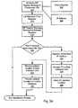
- a flow diagram 200illustrates a method for identifying communication device location in accordance with one or more embodiments of the present invention.
- a requestis received to initially register or enroll a user (block 205 ).
- This usermay be, for example, an individual or entity that contacts a telecommunications provider for service.
- the useris registered by receiving and entering, for example, the name and contact information for the user.
- the contact information for the usermay include, but is not limited to, the user's home address, billing address, payment form, email address, telephone number, and/or the like.
- the telecommunications providertypically assigns one or more telephone numbers through which communication devices associated with the user can be accessed.
- this process of registrationis facilitated using an Internet website.
- a potential customeraccesses a website maintained by a telecommunications service provider.
- the potential customerenters contact and payment information.
- the telecommunications services providerprovides the customer with a telephone number that is provisioned to direct communications to a communication device used by the customer.
- the telecommunications services provider or usermay port the user's existing number to the provider (LNP).
- a primary location of the useris identified (block 210 ), along with one or more alternative locations for the user (block 215 ).
- the primary locationwould be where the user would most likely be found, and the alternative locations would be locations that the user frequents.
- the usermay be an individual with the individual's home address being the primary location.
- the home addresscan be maintained in a format that can be used by a PSAP in disbursing emergency services personnel.
- the primary locationmay be a street address of the individual's home. Based on the disclosure provided herein, one of ordinary skill in the art will recognize various other location formats that may be used in accordance with embodiments of the present invention.
- the locationsmay be recorded in longitude and latitude coordinates satisfactory for access using a GPS guidance system.
- Alternative locationsmay be the individual's work address, the address of a friend or relative's house, the address of a frequented hotel, and/or the like.
- the list of locationsis entered by a user via a website maintained by the telecommunications service provider.
- a predefined location list(block 220 ) which is associated with the user.
- this location listis associated with each phone number assigned to the user.
- this listcan be dynamic allowing the user to add, delete, and change locations from the predefined location list when such changes are appropriate.
- changescan be made to the list of locations by indicating a new current physical location via a voice response unit as described below. Further, where a particular location is not used for a long period of time, it may be removed from the list. In other cases, the list may be modified through access to the website maintained by the telecommunications service provider.
- this predefined location listis associated with a device used by the user.
- a device used by the userFor example, when the user registers with the system, one or more communication devices utilized by the user are associated with the predefined location list. This may include, for example, associating a serial number or some other identifying feature of a device with the predefined location list.
- a communication deviceaccesses the network and registers/re-registers itself with the telecommunications service provider (block 225 ).
- the registration accessmay be done automatically based upon a preset period, and/or upon trying to make a phone call using the network.
- various informationis provided to the telecommunications service provider including, but not limited to, the call back number for the originating communication device and origination information related to the call.
- the origination informationincludes an IP address associated with the communication device originating the call.
- One or more methodsmay be used to determine a change in device location including, but not limited to, a user of the device indicating that the device location has changed, a change in an IP address of the communication device, access to a different load balancer by the communication device, and/or an automatic locating mechanism such as, for example, GPS capability associated with the communication device.
- FIG. 2Bone embodiment of block 230 is described in greater detail.
- the new coordinatesare updated to be the current physical location of the communication device (block 245 ). In some cases, this can include providing the newly received coordinates to data collection unit 112 which in turn updates the location information to location database 117 . Before the update to the location database, the GPS coordinates may be converted to address information useful in dispatching emergency personnel. This may include converting the GPS coordinate information to street address information. As another example, updating location database 117 with the most recent GPS location may be done directly without utilizing the data collection unit. Where no substantial change in location is indicated by the GPS coordinates (block 240 ), the existing location information for the communication device is used (block 260 ).
- the load balancerdetermines if the communication device is accessing the network using the same load balancer used in a prior access (block 255 ). More particularly, when a device accesses a load balancer, the load balancer queries the load balancer cache to determine registration status or other preferences about the communication device. Where such preferences are found, it is assumed that the communication device accessed the current load balancer last time the communication device accessed the network. Alternatively, where such preferences are not found, the load balancer creates a device record in its cache and it is assumed that a different load balancer was used last time the communication device accessed the network. Access via a different load balancer suggests that the communication device may have moved.
- the user utilizing the communication deviceis queried for updated location information (block 265 ). In some cases, this can include connecting the communication device to data collection unit 112 which performs the query.
- Location informationis received from the user (block 285 ), and the location information is recorded in a location database in association with a designation of the communication device (block 290 ).
- the designation of the communication devicecan be, for example, a telephone number of the communication device.
- This updated location informationcan be accessed indirectly by a call to an ALI database as described in more detail below in relation to FIG. 3 .
- data collection unit 112is a Voice Response Unit (VRU) that presents a selection menu with the primary location and one or more alternative locations.
- This menucan be audibly provided to the user via the communication device, and the user can select one of the provided locations or select “other” and provide a new location not previously included in the list of locations.
- the list of locationsincludes the user's home address and Work address and the user is at the home address, the user would select the home address.
- the userwould select “other” and verbally say the address of the friend's house. This new location would be added to the list of locations.
- the list of locationsmay be presented in an order where the most likely address is presented first followed by less likely addresses in descending order. Further, based on the disclosure provided herein, one of ordinary skill in the art will recognize that some of the locations can be removed from the list based on non-use. It should also be noted that other mechanisms for querying the user for location information can be used in accordance with embodiments of the present invention.
- the communication devicemay have a display and data collection unit 112 may be capable of displaying a list of location options via the display. In such a case, the user can select from the displayed locations, or enter an alternative location.
- the status of the deviceis indicated as active allowing the network to service calls from the device (block 295 ).
- the device location update (block 230 )fails to complete, the call is still serviced by the network.
- the predefined location listis not initially populated, but is rather dynamically formed by entering a new location in the list each time the user accesses the telecommunications network from a potentially different location. Over time, the list of locations becomes larger as the user utilizes the telecommunications network from different locations.
- a flow diagram 300depicts a more particular embodiment of the present invention for facilitating emergency calls.
- a SIP endpointrepresented by one of communication devices 190 , 192 , 196 sends a SIP Register Message to a provisioned URL (block 303 ).
- the SIP Register Messageincludes the telephone number (block 306 ) for the communication device, as well as the IP address (block 309 ) of the communication device.
- the SIP register messagegoes to load balancer 187 , and load balancer 187 redirects the originating communication device based on one or more routing rules to registrar 116 .
- This redirectioncan include a SIP Moved Temporarily Message with one or more redirect URLs.
- the communication deviceuses the first of the redirect URLs as the destination of the original SIP Register Message for a period specified in the Moved Temporarily Message.
- the first URLindicates NTM 198 and based on the IP address of the communication device and the port on which NTM 198 received the request, NTM 198 directs the SIP Register Message to registrar server 116 (block 316 ).
- registrar server 116When registrar server 116 receives the SIP Register Message, it may authenticate the communication device by sending back a SIP Authorize Response. Such a response notifies the communication device that it needs to send a subsequent SIP Register Message with a valid username and password. Registrar server 116 then accesses subscriber information with the username and password to validate the registration.
- registrar server 116determines if the IP address of the communication device is the same as that used last time the communication device accessed the network (block 319 ). Where a different IP address is detected (block 319 ), registrar 116 stores the newly received IP address as the current IP address (block 323 ) and sets up a call between the communication device and data collection unit 112 (block 326 ). Where data collection unit 112 is a voice response unit, registrar 116 uses SIP signaling to invite the VRU to join a call. Because registrar server 116 does not yet have a Session Description Protocol (SDP) for the communication device, it sends a null SDP to the VRU placing it on hold.
- SDPSession Description Protocol
- registrar server 116When registrar server 116 receives the SDP from the VRU, registrar server 116 sends a SIP Invite to the communication device with the SDP for the VRU. The communication device returns its SDP to registrar server 116 . This return from the communication device may occur during ringing so registrar server 116 can re-Invite the VRU before the call is answered. In addition, registrar server 116 uses the SDP from the communication device to send a SIP re-Invite to the VRU. When the VRU receives the SIP Invite, it takes the phone off hold, and waits for call answer. When the call answer occurs, the VRU begins playing menu options querying a user of the communication device for location information (block 329 ).
- the usercan hear the menu options via the communication device.
- the usercan respond to the menu options by indicating a current location of the communication device which is received by the VRU (block 333 ).
- the VRUcan perform some level of authentication to determine whether the accessing user is authenticated.
- the VRUupdates location database 117 and associates the received location information with the telephone number of the communication device (block 336 ).
- updating location database 117is done via a message sent in XML format from the VRU to location database 117 . This completes the registration process which is periodically repeated, or performed on power up of the TA.
- the callmay be automatically set up as previously described, or the user may be encouraged to call the VRU.
- the usercan be encouraged to call the VRU in one of various ways including sending the user a voicemail, email or other message indicating that the user should call the VRU, changing the dial tone of the communication device used by the user, and/or the like.
- the dial tonecould be changed from a standard dial tone to, for example, a stutter tone or other audible indicator played to the phone when the user picks up the receiver after changing IP addresses. This could indicate that the user needs to dial into the VRU and provide updated location information.
- a usermay be directed to a website to update their location information.
- a usermay be sent a voicemail, email, or a modified dial tone encouraging the user to log onto a particular website and update location information.
- the website receiving the updated location informationmay provide that location information to location database 117 .
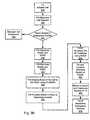
- a flow diagram 301depicts call completion processes that can be performed in accordance with one or more embodiments of the present invention.
- a TAinitiates a call (block 332 ).
- the callincludes the telephone number of the originating TA and the telephone number of the destination. It is determined if the call is an emergency call (block 343 ). In one particular case, this determination is made by determining whether the telephone number of the destination is “911”. Where the call is a non-emergency call (block 343 ), standard call termination is utilized to complete the call (block 346 ).
- feature server 114requests contact information for the PSAP responsible for servicing emergency calls from the geographic area where the TA is located (block 349 ).
- the requested informationincludes an Emergency Services Routing Number (“ESRN”) that uniquely identifies the appropriate PSAP, and an Emergency Services Request Key (“ESQK”) that alerts the PSAP that an indirect lookup is necessary to determine the location and call back number for the communication device.
- ESRNEmergency Services Routing Number
- ESQKEmergency Services Request Key
- the feature serverreceives the requested ESRN and ESQK (block 353 ), and initiates routing of the emergency call to the PSAP using the ESRN (block 353 ).
- Routing the emergency call to the PSAPincludes setting up a media communication path from voice network 110 to the PSAP (e.g., PSAP 140 ) via a gateway (e.g., gateway 135 ) and a PSTN (e.g., PSTN 125 ) local to the PSAP.
- voice network 110enjoys a more direct link to the PSTN allowing voice network 110 to transmit information to the PSAP without traversing the PSTN. This possibility is depicted in FIG. 1A , where a direct connection 199 from voice network 110 to PSAP 140 is shown.
- SR TrunkSelective Router Trunk
- voice network 100routes the call to the SR Trunk, and if that fails to the PSAP admin line using the caller's phone number.
- the telephone number for the TAis replaced by the ESQK (block 359 ).
- the PSAPreceives the routed call and uses the ESQK to access ALI database 118 (block 363 ). Based on the received ESQK, ALI database 418 accesses location database 117 (block 366 ) which returns the location and telephone number for the TA (block 369 ).
- the PSAPcan use the location information to dispatch emergency services, and the telephone number of the TA to call back where the call is lost (block 373 ).
- ESQKis a specialized token used for one particular implementation, and that other tokens or substitute numbers may be used in accordance with other embodiments of the present invention.
- voice network 110may be capable of generating its own numbers for passage to a PSTN and operation similar to that previously described as an ESQK. These numbers would cause the PSTN to access a database in voice network 110 to find out call back and location information.
- other routing indicators besides the ESRNmay be available for use in directing an emergency call to the appropriate PSAP.
- more than one telephone numberis associated with a user and/or communication device.
- these telephone numberscould each be associated with a physical location and when a user picks a particular telephone number, they are also picking the physical location associated with that telephone number.
- the userselects to use one of the telephone numbers, they may also be able to select to forward calls received on all the other telephone numbers to the selected telephone number.
- the registrar serverknows the other telephone numbers, the registrar server can set up the call forwarding. It could also be possible for the voice network to translate the original called number to the currently registered number on the feature server or Edge Proxy Server (EPS) fronting the feature server.
- EPSEdge Proxy Server
- An ALI databasecan be updated to include all of the telephone numbers along with the associated physical locations, thus allowing a PSAP to use the received telephone number to access the ALI database and determine a physical location of the call origination.
- the voice networkmay still connect the emergency call using the admin line of the PSAP, and directing the PSAP to the ALI database for physical location information as previously described.
- the callmay be patched directly to the PSAP, and the PSAP can access the physical location information from the ALI database much as it would do if a traditional land line was used to make the emergency call.
- the communication device used to access the voice networkis communicably coupled to the voice network via a broadband interface such as, but not limited to, a DSL or Cable Modem connection.
- a broadband interfacesuch as, but not limited to, a DSL or Cable Modem connection.
- the geographic locationis associated with the particular broadband interface.
- the location of the broadband interfacecan be used as the location of the communication device.
- the location of the broadband interfaceis maintained in a central database of an ISP.
- call processingprogresses similar to that described in relation to FIG. 2 , except that instead of collecting data via the VRU, the data is gathered automatically from an available database.
- Registrar server 116can use this location information to update the location database as previously described.
- System 400includes a voice network 411 with one or more registrar servers 416 , one or more feature servers 414 , one or more data collection units 412 , and one or more location databases 417 .
- Registrar server 416 , feature server 414 , data collection unit 412 , and location database 417are similar to the commonly named components described in relation to FIG. 1A above.
- Voice network 411is communicably coupled to public internet 185 via NTM 498 .
- Public internet 185is communicably coupled to one or more communication devices 190 , 192 , 196 via load balancer 187 as described in more detail above in relation to FIG. 1A .
- System 400also includes an ALI database 418 and a service network 410 communicably coupled to voice network 411 via a session border controller 403 .
- Service network 410includes one or more feature servers 413 operable to receive communication information and instructions, and to terminate the communication information in accordance with the instructions.
- Service network 410is communicably coupled to PSTN 155 via gateway 165 .
- PSAP 170is accessible via PSTN 155 as described in more detail above in relation to FIG. 1A .
- the location and call back number for each of communication devices 190 , 192 , 196is registered with voice network 411 and the information is maintained in location database 417 .
- the callis ultimately directed to feature server 414 .
- Feature server 414requests an ESRN and ESQK in relation to servicing the call.
- This ESRN and ESQK, along with control of the emergency callare then passed to feature server 413 .
- feature server 413directs the call to the PSAP (e.g. PSAP 170 ) indicated by the ESRN and including the ESQK as the call back number for the originating communication device.
- PSAPe.g. PSAP 170
- PSTN 155uses the received ESQK to access ALI database 418 to request the location of the originating communication device. Based on the received ESQK, ALI database 418 accesses location database 417 to access the location and call back number for the originating communication device. ALI database passes the location and callback information of the originating communication device to PSTN 155 , and PSTN 155 fields the call and where necessary dispatches appropriate emergency services.
- service network 410can terminate emergency calls to the appropriate PSTN without knowing the underlying information about a user of the originating communication device.
- voice network 411can provide emergency telephone service to its customers without implementing capability to terminate the calls, and without having to disclose information about its customer base to outsiders. This can provide an effective way for offering emergency telephone services for a VoIP service provider.
- a flow diagram 500illustrates a method in accordance with some embodiments of the present invention for terminating third party emergency calls.
- a communication device previously registered with voice network 411initiates a call (block 532 ).
- This registration processincludes determining a location of the communication device, and updating that location along with the callback number for the communication device with location database 417 . In some cases, this registration process proceeds similar to that described above in relation to FIG. 3A .
- the call initiated by the communication deviceincludes the telephone number of the originating TA and the telephone number of the destination.
- the callis received by feature server 414 (block 534 ), and the destination telephone number is used to determine if the call is an emergency call (block 543 ). Where the call is a non-emergency call (block 543 ), voice network 411 uses standard call termination to complete the call (block 546 ).
- feature server 414requests contact information for the PSAP responsible for servicing emergency calls from the geographic area where the TA is located (block 549 ).
- the requested informationincludes the ESRN for the appropriate PSAP, and an ESQK to be used in relation with the PSAP.
- Feature server 414receives the requested ESRN and ESQK (block 553 ), and replaces the call back number of the originating communication device with the ESQK (block 555 ). With this done, feature server 414 transfers control of the emergency call to feature server 413 (block 557 ). In transferring the call, feature server 414 indicates that the call should be directed to the PSAP indicated by the ESRN.
- feature serverprovides a means for obtaining location information and the callback number for the originating communication device without disclosing information (e.g., the call back number) of the user originating the call.
- voice network 411can guard its customer information from service network 410 .
- feature server 414Having received control of the call and the ESQK and ESRN, feature server 414 initiates routing of the call to the PSAP indicated by the ESRN (block 559 ).
- the PSAP receiving the callaccesses ALI database 418 using the received ESQK (block 563 ).
- ALI database 418accesses location database 417 (block 566 ) which returns the location and telephone number for the originating communication device (block 569 ).
- the PSAPcan use the location information to dispatch emergency services, and the telephone number of the TA to call back where the call is lost (block 573 ).
- the present inventionprovides novel systems, methods and arrangements for detecting device locations; querying for device location, reporting device location, and/or dynamically registering devices. While detailed descriptions of one or more embodiments of the invention have been given above, various alternatives, modifications, and equivalents will be apparent to those skilled in the art without varying from the spirit of the invention. Therefore, the above description should not be taken as limiting the scope of the invention, which is defined by the appended claims.
Landscapes
- Engineering & Computer Science (AREA)
- Signal Processing (AREA)
- Business, Economics & Management (AREA)
- Computer Networks & Wireless Communication (AREA)
- Emergency Management (AREA)
- Marketing (AREA)
- Telephonic Communication Services (AREA)
Abstract
Description
Claims (24)
Priority Applications (2)
| Application Number | Priority Date | Filing Date | Title |
|---|---|---|---|
| US11/009,216US8768350B2 (en) | 2004-12-09 | 2004-12-09 | Systems and methods for locating endpoints in a communication network |
| US14/321,731US20150156320A1 (en) | 2004-12-09 | 2014-07-01 | Systems and methods for locating endpoints in a communication network |
Applications Claiming Priority (1)
| Application Number | Priority Date | Filing Date | Title |
|---|---|---|---|
| US11/009,216US8768350B2 (en) | 2004-12-09 | 2004-12-09 | Systems and methods for locating endpoints in a communication network |
Related Child Applications (1)
| Application Number | Title | Priority Date | Filing Date |
|---|---|---|---|
| US14/321,731ContinuationUS20150156320A1 (en) | 2004-12-09 | 2014-07-01 | Systems and methods for locating endpoints in a communication network |
Publications (2)
| Publication Number | Publication Date |
|---|---|
| US20120243466A1 US20120243466A1 (en) | 2012-09-27 |
| US8768350B2true US8768350B2 (en) | 2014-07-01 |
Family
ID=46877298
Family Applications (2)
| Application Number | Title | Priority Date | Filing Date |
|---|---|---|---|
| US11/009,216Active2028-12-24US8768350B2 (en) | 2004-12-09 | 2004-12-09 | Systems and methods for locating endpoints in a communication network |
| US14/321,731AbandonedUS20150156320A1 (en) | 2004-12-09 | 2014-07-01 | Systems and methods for locating endpoints in a communication network |
Family Applications After (1)
| Application Number | Title | Priority Date | Filing Date |
|---|---|---|---|
| US14/321,731AbandonedUS20150156320A1 (en) | 2004-12-09 | 2014-07-01 | Systems and methods for locating endpoints in a communication network |
Country Status (1)
| Country | Link |
|---|---|
| US (2) | US8768350B2 (en) |
Cited By (2)
| Publication number | Priority date | Publication date | Assignee | Title |
|---|---|---|---|---|
| US20170180093A1 (en)* | 2015-12-21 | 2017-06-22 | Intel IP Corporation | Communication device and method for performing radio communication |
| US9998526B2 (en) | 2004-05-03 | 2018-06-12 | Level 3 Communications, Llc | Registration redirect server |
Families Citing this family (5)
| Publication number | Priority date | Publication date | Assignee | Title |
|---|---|---|---|---|
| US9843557B2 (en) | 2004-12-09 | 2017-12-12 | Level 3 Communications, Llc | Systems and methods for dynamically registering endpoints in a network |
| US7961717B2 (en)* | 2005-05-12 | 2011-06-14 | Iposi, Inc. | System and methods for IP and VoIP device location determination |
| US9258386B2 (en)* | 2005-11-18 | 2016-02-09 | Telecommunication Systems, Inc. | Voice over internet protocol (VoIP) mobility detection |
| US8761721B2 (en) | 2011-07-27 | 2014-06-24 | Verizon Patent And Licensing Inc. | Integrated emergency call support for mobile and nomadic devices |
| US11106263B2 (en)* | 2019-01-31 | 2021-08-31 | Sapient Industries, Inc. | Region-based electrical intelligence system |
Citations (103)
| Publication number | Priority date | Publication date | Assignee | Title |
|---|---|---|---|---|
| US5742666A (en) | 1994-10-05 | 1998-04-21 | Tele Digital Development, Inc. | Emergency mobile telephone |
| US5774668A (en) | 1995-06-07 | 1998-06-30 | Microsoft Corporation | System for on-line service in which gateway computer uses service map which includes loading condition of servers broadcasted by application servers for load balancing |
| US5812769A (en) | 1995-09-20 | 1998-09-22 | Infonautics Corporation | Method and apparatus for redirecting a user to a new location on the world wide web using relative universal resource locators |
| US5819092A (en) | 1994-11-08 | 1998-10-06 | Vermeer Technologies, Inc. | Online service development tool with fee setting capabilities |
| JPH10307783A (en) | 1997-05-07 | 1998-11-17 | N T T Data:Kk | Site access control system and recording medium |
| WO1998057275A2 (en) | 1997-06-12 | 1998-12-17 | Telia Ab | Arrangement for load sharing in computer networks |
| US5920701A (en) | 1995-01-19 | 1999-07-06 | Starburst Communications Corporation | Scheduling data transmission |
| US5956716A (en) | 1995-06-07 | 1999-09-21 | Intervu, Inc. | System and method for delivery of video data over a computer network |
| US6052718A (en) | 1997-01-07 | 2000-04-18 | Sightpath, Inc | Replica routing |
| US6078943A (en) | 1997-02-07 | 2000-06-20 | International Business Machines Corporation | Method and apparatus for dynamic interval-based load balancing |
| US6081835A (en) | 1996-04-04 | 2000-06-27 | British Telecommunications Public Limited Company | Internet server and method of controlling an internet server |
| US6108703A (en) | 1998-07-14 | 2000-08-22 | Massachusetts Institute Of Technology | Global hosting system |
| US6112239A (en) | 1997-06-18 | 2000-08-29 | Intervu, Inc | System and method for server-side optimization of data delivery on a distributed computer network |
| US6138026A (en)* | 1998-06-16 | 2000-10-24 | Ericsson Inc. | Method and apparatus for locating a wireless communication device |
| US6154744A (en) | 1995-06-07 | 2000-11-28 | Intervu, Inc. | System and method for optimized storage and retrieval of data on a distributed computer network |
| US6167427A (en) | 1997-11-28 | 2000-12-26 | Lucent Technologies Inc. | Replication service system and method for directing the replication of information servers based on selected plurality of servers load |
| US6175869B1 (en) | 1998-04-08 | 2001-01-16 | Lucent Technologies Inc. | Client-side techniques for web server allocation |
| US6185619B1 (en) | 1996-12-09 | 2001-02-06 | Genuity Inc. | Method and apparatus for balancing the process load on network servers according to network and serve based policies |
| US6185601B1 (en) | 1996-08-02 | 2001-02-06 | Hewlett-Packard Company | Dynamic load balancing of a network of client and server computers |
| US6187160B1 (en) | 1998-06-19 | 2001-02-13 | Leybold Systems Gmbh | Apparatus for the coating of substrates in a vacuum chamber |
| US6243760B1 (en) | 1997-06-24 | 2001-06-05 | Vistar Telecommunications Inc. | Information dissemination system with central and distributed caches |
| US6314465B1 (en) | 1999-03-11 | 2001-11-06 | Lucent Technologies Inc. | Method and apparatus for load sharing on a wide area network |
| US20010042139A1 (en) | 2000-03-31 | 2001-11-15 | Aprisma Management Technologies | Replicated resource management system for managing resources in a distributed application and maintaining a relativistic view of state |
| US6330605B1 (en) | 1998-11-19 | 2001-12-11 | Volera, Inc. | Proxy cache cluster |
| US20020031107A1 (en) | 2000-08-31 | 2002-03-14 | Hongyi Li | Methods and apparatus for supporting micro-mobility within a radio access network |
| US20020032777A1 (en) | 2000-09-11 | 2002-03-14 | Yoko Kawata | Load sharing apparatus and a load estimation method |
| US6374299B1 (en) | 1998-02-05 | 2002-04-16 | Merrill Lynch & Co. Inc. | Enhanced scalable distributed network controller |
| US20020078263A1 (en) | 2000-12-18 | 2002-06-20 | Darling Christopher L. | Dynamic monitor and controller of availability of a load-balancing cluster |
| US20020078209A1 (en) | 2000-12-15 | 2002-06-20 | Luosheng Peng | Apparatus and methods for intelligently providing applications and data on a mobile device system |
| US6412004B1 (en) | 1997-03-27 | 2002-06-25 | Microsoft Corporation | Metaserver for a multimedia distribution network |
| US6412002B1 (en) | 1999-11-15 | 2002-06-25 | Ncr Corporation | Method and apparatus for selecting nodes in configuring massively parallel systems |
| US6438652B1 (en) | 1998-10-09 | 2002-08-20 | International Business Machines Corporation | Load balancing cooperating cache servers by shifting forwarded request |
| US20020141401A1 (en) | 1999-07-01 | 2002-10-03 | Mark Albert | Distributing packets among multiple tiers of network appliances |
| US20020166117A1 (en) | 2000-09-12 | 2002-11-07 | Abrams Peter C. | Method system and apparatus for providing pay-per-use distributed computing resources |
| US6484204B1 (en) | 1997-05-06 | 2002-11-19 | At&T Corp. | System and method for allocating requests for objects and managing replicas of objects on a network |
| US20020194342A1 (en) | 2001-06-18 | 2002-12-19 | Transtech Networks Usa, Inc. | Content-aware application switch and methods thereof |
| US20020194335A1 (en) | 2001-06-19 | 2002-12-19 | Maynard William Pat | Method and apparatus for load balancing |
| US20030007622A1 (en) | 1998-08-04 | 2003-01-09 | Kalmanek Charles Robert | Method for allocating network resources |
| US20030009559A1 (en) | 2001-07-09 | 2003-01-09 | Naoya Ikeda | Network system and method of distributing accesses to a plurality of server apparatus in the network system |
| US20030012344A1 (en) | 2001-07-10 | 2003-01-16 | Rita Agarwal | System and a method for emergency services |
| US20030041238A1 (en) | 2001-08-15 | 2003-02-27 | International Business Machines Corporation | Method and system for managing resources using geographic location information within a network management framework |
| US20030050051A1 (en)* | 2000-03-18 | 2003-03-13 | Vilander Harri Tapani | IP communication in a cellular telecommunications system |
| US20030065761A1 (en) | 2001-09-28 | 2003-04-03 | Nevton Cereja | System and method of creating and maintaining a replicated naming service to support a telecommunications network |
| EP1307018A1 (en) | 2001-10-24 | 2003-05-02 | Sun Microsystems, Inc. | Load balancing unit and method of its operation |
| US6574612B1 (en) | 1999-02-19 | 2003-06-03 | International Business Machines Corporation | License management system |
| US20030105865A1 (en) | 1999-09-03 | 2003-06-05 | Fastforward Networks, Inc. | Proximity-based redirection system for robust and scalable service-node location in an internetwork |
| US20030108000A1 (en) | 2001-12-07 | 2003-06-12 | Telefonaktiebolaget Lm Ericsson (Pub1) | Service access system and method in a telecommunications network |
| US6601084B1 (en) | 1997-12-19 | 2003-07-29 | Avaya Technology Corp. | Dynamic load balancer for multiple network servers |
| US6606643B1 (en) | 2000-01-04 | 2003-08-12 | International Business Machines Corporation | Method of automatically selecting a mirror server for web-based client-host interaction |
| US20030156577A1 (en)* | 2002-02-19 | 2003-08-21 | Mitel Knowledge Corporation | Solution to enhanced emergency services (e.g. 911) for IP telephony systems |
| US6636499B1 (en) | 1999-12-02 | 2003-10-21 | Cisco Technology, Inc. | Apparatus and method for cluster network device discovery |
| US6665702B1 (en) | 1998-07-15 | 2003-12-16 | Radware Ltd. | Load balancing |
| US6678357B2 (en) | 2001-09-26 | 2004-01-13 | Siemens Information And Communication Networks, Inc. | Internet protocol (IP) emergency connections (ITEC) telephony |
| US6722211B1 (en) | 2001-11-29 | 2004-04-20 | Viasys Healthcare, Critical Care Division | Multi-stage variable orifice flow obstruction sensor |
| US6760775B1 (en) | 1999-03-05 | 2004-07-06 | At&T Corp. | System, method and apparatus for network service load and reliability management |
| US20040143662A1 (en) | 2001-08-15 | 2004-07-22 | Nokia Corporation | Load balancing for a server farm |
| US20040152469A1 (en) | 2003-01-30 | 2004-08-05 | Petteri Yla-Outinen | Message-based conveyance of load control information |
| US6778496B1 (en) | 2000-06-07 | 2004-08-17 | Lucent Technologies Inc. | Distributed call admission and load balancing method and apparatus for packet networks |
| US20040160947A1 (en) | 2001-03-20 | 2004-08-19 | Hardy William Geoffrey | Voip systems |
| US6795858B1 (en) | 2000-12-29 | 2004-09-21 | Cisco Technology, Inc. | Method and apparatus for metric based server selection |
| US20040205192A1 (en) | 2003-03-12 | 2004-10-14 | Microsoft Corporation | End-point identifiers in SIP |
| US20040264481A1 (en) | 2003-06-30 | 2004-12-30 | Darling Christopher L. | Network load balancing with traffic routing |
| US20050010653A1 (en) | 1999-09-03 | 2005-01-13 | Fastforward Networks, Inc. | Content distribution system for operation over an internetwork including content peering arrangements |
| US6845092B2 (en) | 2001-07-13 | 2005-01-18 | Qualcomm Incorporated | System and method for mobile station authentication using session initiation protocol (SIP) |
| US20050022203A1 (en) | 1998-07-15 | 2005-01-27 | Radware Ltd. | Load balancing |
| US6857021B1 (en) | 1998-10-30 | 2005-02-15 | 3Com Corporation | Proximity-based registration on a data network telephony system |
| US20050044141A1 (en) | 2001-02-19 | 2005-02-24 | Heino Hameleers | Method and system for multiple hosts anycast routing |
| US20050055435A1 (en) | 2003-06-30 | 2005-03-10 | Abolade Gbadegesin | Network load balancing with connection manipulation |
| US20050085257A1 (en)* | 2003-10-01 | 2005-04-21 | Laird Mark D. | Mobile emergency notification system |
| US6886035B2 (en) | 1996-08-02 | 2005-04-26 | Hewlett-Packard Development Company, L.P. | Dynamic load balancing of a network of client and server computer |
| US20050091407A1 (en) | 2003-10-23 | 2005-04-28 | Tivox Systems, Inc | Multi-network exchange system for telephony applications |
| US20050101327A1 (en)* | 2003-11-08 | 2005-05-12 | Hyun-Ho Nam | Roaming service method and system in multi-zone private wireless network systems |
| US20050136925A1 (en)* | 2003-12-17 | 2005-06-23 | Toshiaki Yamauchi | Variable expiration parameter of a wireless communication device based upon signal strength |
| US20050169438A1 (en)* | 2004-01-30 | 2005-08-04 | Valerie Binning | System & methods for providing location signals/indicators when 911 dialed |
| US6938031B1 (en) | 2001-10-19 | 2005-08-30 | Data Return Llc | System and method for accessing information in a replicated database |
| US20050197767A1 (en)* | 2004-02-05 | 2005-09-08 | Nortrup Edward H. | Smart answering machine |
| US20050213716A1 (en) | 2004-03-23 | 2005-09-29 | Yinjun Zhu | Solutions for voice over internet protocol (VoIP) 911 location services |
| US6963557B2 (en) | 2003-03-29 | 2005-11-08 | Intrado Inc. | System and method for routing telephone calls involving internet protocol network |
| US20060013147A1 (en) | 2004-05-03 | 2006-01-19 | Level 3 Communications, Inc. | Registration redirect server |
| US7000016B1 (en) | 2001-10-19 | 2006-02-14 | Data Return Llc | System and method for multi-site clustering in a network |
| US20060056388A1 (en)* | 2004-08-24 | 2006-03-16 | Comcast Cable Holdings, Llc | Method and system for locating a voice over internet protocol (VoIP) device connected to a network |
| US20060064478A1 (en) | 2004-05-03 | 2006-03-23 | Level 3 Communications, Inc. | Geo-locating load balancing |
| US20060069776A1 (en) | 2004-09-15 | 2006-03-30 | Shim Choon B | System and method for load balancing a communications network |
| US7031728B2 (en)* | 2004-09-21 | 2006-04-18 | Beyer Jr Malcolm K | Cellular phone/PDA communication system |
| US20060112170A1 (en) | 2004-05-03 | 2006-05-25 | Craig Sirkin | Geo-locating load balancing |
| US7076541B1 (en) | 2000-06-05 | 2006-07-11 | Register.Com, Inc. | Method and apparatus providing distributed domain management capabilities |
| US7088718B1 (en) | 2002-03-19 | 2006-08-08 | Cisco Technology, Inc. | Server load balancing using IP option field approach to identify route to selected server |
| US7103647B2 (en) | 1999-08-23 | 2006-09-05 | Terraspring, Inc. | Symbolic definition of a computer system |
| US7110393B1 (en) | 2001-02-28 | 2006-09-19 | 3Com Corporation | System and method for providing user mobility handling in a network telephony system |
| US7111052B1 (en) | 2000-04-24 | 2006-09-19 | Sprint Communications Company L.P. | Network shell |
| US20060235980A1 (en) | 2004-09-27 | 2006-10-19 | Netdevices, Inc. | Enabling VoIP Calls to be Initiated When a Call Server is Unavailable |
| US7136651B2 (en) | 2004-08-30 | 2006-11-14 | Tatara Systems, Inc. | Mobile services control platform providing a converged voice service |
| US20060265467A1 (en) | 2003-03-28 | 2006-11-23 | Kyuo Jang | P2p service method |
| US7177399B2 (en)* | 2004-02-27 | 2007-02-13 | Nortel Network Limited | Determining the geographical location from which an emergency call originates in a packet-based communications network |
| US7194552B1 (en) | 1999-03-22 | 2007-03-20 | Eric Schneider | Method, product, and apparatus for requesting a network resource |
| US20070254625A1 (en) | 2006-04-28 | 2007-11-01 | Edge Stephen W | System and method for supporting voice call continuity for voip emergency calls |
| US7308481B2 (en) | 2003-01-20 | 2007-12-11 | Hitachi, Ltd. | Network storage system |
| US7328281B2 (en) | 2002-05-30 | 2008-02-05 | Hitachi, Ltd. | Address translation equipment, terminal equipment and mobile communication method |
| US7333459B2 (en) | 2000-01-27 | 2008-02-19 | Telefonaktiebolaget Lm Ericsson (Publ) | Allocation of a server address to a terminal |
| US7342928B2 (en) | 2003-04-30 | 2008-03-11 | France Telecom | Method and system for accessing a peer-to-peer network |
| US7379458B2 (en) | 2001-12-06 | 2008-05-27 | Fujitsu Limited | Server load sharing system |
| US20090070406A1 (en) | 2004-12-09 | 2009-03-12 | Level 3 Communications, Inc. | Systems and methods for dynamically registering endpoints in a network |
| US7734019B1 (en) | 2004-12-09 | 2010-06-08 | Level 3 Communications, Llc | Systems and methods for third party emergency call termination |
- 2004
- 2004-12-09USUS11/009,216patent/US8768350B2/enactiveActive
- 2014
- 2014-07-01USUS14/321,731patent/US20150156320A1/ennot_activeAbandoned
Patent Citations (111)
| Publication number | Priority date | Publication date | Assignee | Title |
|---|---|---|---|---|
| US5742666A (en) | 1994-10-05 | 1998-04-21 | Tele Digital Development, Inc. | Emergency mobile telephone |
| US5819092A (en) | 1994-11-08 | 1998-10-06 | Vermeer Technologies, Inc. | Online service development tool with fee setting capabilities |
| US5920701A (en) | 1995-01-19 | 1999-07-06 | Starburst Communications Corporation | Scheduling data transmission |
| US6154744A (en) | 1995-06-07 | 2000-11-28 | Intervu, Inc. | System and method for optimized storage and retrieval of data on a distributed computer network |
| US5774668A (en) | 1995-06-07 | 1998-06-30 | Microsoft Corporation | System for on-line service in which gateway computer uses service map which includes loading condition of servers broadcasted by application servers for load balancing |
| US5956716A (en) | 1995-06-07 | 1999-09-21 | Intervu, Inc. | System and method for delivery of video data over a computer network |
| US5812769A (en) | 1995-09-20 | 1998-09-22 | Infonautics Corporation | Method and apparatus for redirecting a user to a new location on the world wide web using relative universal resource locators |
| US6081835A (en) | 1996-04-04 | 2000-06-27 | British Telecommunications Public Limited Company | Internet server and method of controlling an internet server |
| US6886035B2 (en) | 1996-08-02 | 2005-04-26 | Hewlett-Packard Development Company, L.P. | Dynamic load balancing of a network of client and server computer |
| US6185601B1 (en) | 1996-08-02 | 2001-02-06 | Hewlett-Packard Company | Dynamic load balancing of a network of client and server computers |
| US6185619B1 (en) | 1996-12-09 | 2001-02-06 | Genuity Inc. | Method and apparatus for balancing the process load on network servers according to network and serve based policies |
| US6052718A (en) | 1997-01-07 | 2000-04-18 | Sightpath, Inc | Replica routing |
| US6078943A (en) | 1997-02-07 | 2000-06-20 | International Business Machines Corporation | Method and apparatus for dynamic interval-based load balancing |
| US6412004B1 (en) | 1997-03-27 | 2002-06-25 | Microsoft Corporation | Metaserver for a multimedia distribution network |
| US6484204B1 (en) | 1997-05-06 | 2002-11-19 | At&T Corp. | System and method for allocating requests for objects and managing replicas of objects on a network |
| JPH10307783A (en) | 1997-05-07 | 1998-11-17 | N T T Data:Kk | Site access control system and recording medium |
| US6687731B1 (en) | 1997-06-12 | 2004-02-03 | Telia Ab | Arrangement for load sharing in computer networks |
| WO1998057275A2 (en) | 1997-06-12 | 1998-12-17 | Telia Ab | Arrangement for load sharing in computer networks |
| US6112239A (en) | 1997-06-18 | 2000-08-29 | Intervu, Inc | System and method for server-side optimization of data delivery on a distributed computer network |
| US6243760B1 (en) | 1997-06-24 | 2001-06-05 | Vistar Telecommunications Inc. | Information dissemination system with central and distributed caches |
| US6167427A (en) | 1997-11-28 | 2000-12-26 | Lucent Technologies Inc. | Replication service system and method for directing the replication of information servers based on selected plurality of servers load |
| US6601084B1 (en) | 1997-12-19 | 2003-07-29 | Avaya Technology Corp. | Dynamic load balancer for multiple network servers |
| US6374299B1 (en) | 1998-02-05 | 2002-04-16 | Merrill Lynch & Co. Inc. | Enhanced scalable distributed network controller |
| US6175869B1 (en) | 1998-04-08 | 2001-01-16 | Lucent Technologies Inc. | Client-side techniques for web server allocation |
| US6138026A (en)* | 1998-06-16 | 2000-10-24 | Ericsson Inc. | Method and apparatus for locating a wireless communication device |
| US6187160B1 (en) | 1998-06-19 | 2001-02-13 | Leybold Systems Gmbh | Apparatus for the coating of substrates in a vacuum chamber |
| US7103645B2 (en) | 1998-07-14 | 2006-09-05 | Massachusetts Institute Of Technology | Method and system for providing content delivery to a set of participating content providers |
| US6108703A (en) | 1998-07-14 | 2000-08-22 | Massachusetts Institute Of Technology | Global hosting system |
| US20050022203A1 (en) | 1998-07-15 | 2005-01-27 | Radware Ltd. | Load balancing |
| US6665702B1 (en) | 1998-07-15 | 2003-12-16 | Radware Ltd. | Load balancing |
| US20030007622A1 (en) | 1998-08-04 | 2003-01-09 | Kalmanek Charles Robert | Method for allocating network resources |
| US6438652B1 (en) | 1998-10-09 | 2002-08-20 | International Business Machines Corporation | Load balancing cooperating cache servers by shifting forwarded request |
| US6857021B1 (en) | 1998-10-30 | 2005-02-15 | 3Com Corporation | Proximity-based registration on a data network telephony system |
| US6330605B1 (en) | 1998-11-19 | 2001-12-11 | Volera, Inc. | Proxy cache cluster |
| US6574612B1 (en) | 1999-02-19 | 2003-06-03 | International Business Machines Corporation | License management system |
| US6760775B1 (en) | 1999-03-05 | 2004-07-06 | At&T Corp. | System, method and apparatus for network service load and reliability management |
| US6314465B1 (en) | 1999-03-11 | 2001-11-06 | Lucent Technologies Inc. | Method and apparatus for load sharing on a wide area network |
| US7194552B1 (en) | 1999-03-22 | 2007-03-20 | Eric Schneider | Method, product, and apparatus for requesting a network resource |
| US20020141401A1 (en) | 1999-07-01 | 2002-10-03 | Mark Albert | Distributing packets among multiple tiers of network appliances |
| US7103647B2 (en) | 1999-08-23 | 2006-09-05 | Terraspring, Inc. | Symbolic definition of a computer system |
| US20030105865A1 (en) | 1999-09-03 | 2003-06-05 | Fastforward Networks, Inc. | Proximity-based redirection system for robust and scalable service-node location in an internetwork |
| US20050010653A1 (en) | 1999-09-03 | 2005-01-13 | Fastforward Networks, Inc. | Content distribution system for operation over an internetwork including content peering arrangements |
| US6412002B1 (en) | 1999-11-15 | 2002-06-25 | Ncr Corporation | Method and apparatus for selecting nodes in configuring massively parallel systems |
| US6636499B1 (en) | 1999-12-02 | 2003-10-21 | Cisco Technology, Inc. | Apparatus and method for cluster network device discovery |
| US6606643B1 (en) | 2000-01-04 | 2003-08-12 | International Business Machines Corporation | Method of automatically selecting a mirror server for web-based client-host interaction |
| US7333459B2 (en) | 2000-01-27 | 2008-02-19 | Telefonaktiebolaget Lm Ericsson (Publ) | Allocation of a server address to a terminal |
| US20030050051A1 (en)* | 2000-03-18 | 2003-03-13 | Vilander Harri Tapani | IP communication in a cellular telecommunications system |
| US20010042139A1 (en) | 2000-03-31 | 2001-11-15 | Aprisma Management Technologies | Replicated resource management system for managing resources in a distributed application and maintaining a relativistic view of state |
| US7111052B1 (en) | 2000-04-24 | 2006-09-19 | Sprint Communications Company L.P. | Network shell |
| US7076541B1 (en) | 2000-06-05 | 2006-07-11 | Register.Com, Inc. | Method and apparatus providing distributed domain management capabilities |
| US6778496B1 (en) | 2000-06-07 | 2004-08-17 | Lucent Technologies Inc. | Distributed call admission and load balancing method and apparatus for packet networks |
| US20020031107A1 (en) | 2000-08-31 | 2002-03-14 | Hongyi Li | Methods and apparatus for supporting micro-mobility within a radio access network |
| US20020032777A1 (en) | 2000-09-11 | 2002-03-14 | Yoko Kawata | Load sharing apparatus and a load estimation method |
| US20020166117A1 (en) | 2000-09-12 | 2002-11-07 | Abrams Peter C. | Method system and apparatus for providing pay-per-use distributed computing resources |
| US20020078209A1 (en) | 2000-12-15 | 2002-06-20 | Luosheng Peng | Apparatus and methods for intelligently providing applications and data on a mobile device system |
| US20020078263A1 (en) | 2000-12-18 | 2002-06-20 | Darling Christopher L. | Dynamic monitor and controller of availability of a load-balancing cluster |
| US6795858B1 (en) | 2000-12-29 | 2004-09-21 | Cisco Technology, Inc. | Method and apparatus for metric based server selection |
| US20050044141A1 (en) | 2001-02-19 | 2005-02-24 | Heino Hameleers | Method and system for multiple hosts anycast routing |
| US7110393B1 (en) | 2001-02-28 | 2006-09-19 | 3Com Corporation | System and method for providing user mobility handling in a network telephony system |
| US20040160947A1 (en) | 2001-03-20 | 2004-08-19 | Hardy William Geoffrey | Voip systems |
| US20020194342A1 (en) | 2001-06-18 | 2002-12-19 | Transtech Networks Usa, Inc. | Content-aware application switch and methods thereof |
| US20020194335A1 (en) | 2001-06-19 | 2002-12-19 | Maynard William Pat | Method and apparatus for load balancing |
| US20030009559A1 (en) | 2001-07-09 | 2003-01-09 | Naoya Ikeda | Network system and method of distributing accesses to a plurality of server apparatus in the network system |
| US20030012344A1 (en) | 2001-07-10 | 2003-01-16 | Rita Agarwal | System and a method for emergency services |
| US6845092B2 (en) | 2001-07-13 | 2005-01-18 | Qualcomm Incorporated | System and method for mobile station authentication using session initiation protocol (SIP) |
| US20030041238A1 (en) | 2001-08-15 | 2003-02-27 | International Business Machines Corporation | Method and system for managing resources using geographic location information within a network management framework |
| US20040143662A1 (en) | 2001-08-15 | 2004-07-22 | Nokia Corporation | Load balancing for a server farm |
| US6678357B2 (en) | 2001-09-26 | 2004-01-13 | Siemens Information And Communication Networks, Inc. | Internet protocol (IP) emergency connections (ITEC) telephony |
| US20030065761A1 (en) | 2001-09-28 | 2003-04-03 | Nevton Cereja | System and method of creating and maintaining a replicated naming service to support a telecommunications network |
| US6938031B1 (en) | 2001-10-19 | 2005-08-30 | Data Return Llc | System and method for accessing information in a replicated database |
| US7000016B1 (en) | 2001-10-19 | 2006-02-14 | Data Return Llc | System and method for multi-site clustering in a network |
| EP1307018A1 (en) | 2001-10-24 | 2003-05-02 | Sun Microsystems, Inc. | Load balancing unit and method of its operation |
| US6722211B1 (en) | 2001-11-29 | 2004-04-20 | Viasys Healthcare, Critical Care Division | Multi-stage variable orifice flow obstruction sensor |
| US7379458B2 (en) | 2001-12-06 | 2008-05-27 | Fujitsu Limited | Server load sharing system |
| US20030108000A1 (en) | 2001-12-07 | 2003-06-12 | Telefonaktiebolaget Lm Ericsson (Pub1) | Service access system and method in a telecommunications network |
| US7151753B2 (en) | 2001-12-07 | 2006-12-19 | Telefonaktiebolaget Lm Ericsson (Publ) | System and method for establishing a conference call |
| US20030156577A1 (en)* | 2002-02-19 | 2003-08-21 | Mitel Knowledge Corporation | Solution to enhanced emergency services (e.g. 911) for IP telephony systems |
| US7088718B1 (en) | 2002-03-19 | 2006-08-08 | Cisco Technology, Inc. | Server load balancing using IP option field approach to identify route to selected server |
| US7328281B2 (en) | 2002-05-30 | 2008-02-05 | Hitachi, Ltd. | Address translation equipment, terminal equipment and mobile communication method |
| US7308481B2 (en) | 2003-01-20 | 2007-12-11 | Hitachi, Ltd. | Network storage system |
| US20040152469A1 (en) | 2003-01-30 | 2004-08-05 | Petteri Yla-Outinen | Message-based conveyance of load control information |
| US7412521B2 (en) | 2003-03-12 | 2008-08-12 | Microsoft Corporation | End-point identifiers in SIP |
| US20040205192A1 (en) | 2003-03-12 | 2004-10-14 | Microsoft Corporation | End-point identifiers in SIP |
| US20060265467A1 (en) | 2003-03-28 | 2006-11-23 | Kyuo Jang | P2p service method |
| US6963557B2 (en) | 2003-03-29 | 2005-11-08 | Intrado Inc. | System and method for routing telephone calls involving internet protocol network |
| US7342928B2 (en) | 2003-04-30 | 2008-03-11 | France Telecom | Method and system for accessing a peer-to-peer network |
| US20040264481A1 (en) | 2003-06-30 | 2004-12-30 | Darling Christopher L. | Network load balancing with traffic routing |
| US20050055435A1 (en) | 2003-06-30 | 2005-03-10 | Abolade Gbadegesin | Network load balancing with connection manipulation |
| US20050085257A1 (en)* | 2003-10-01 | 2005-04-21 | Laird Mark D. | Mobile emergency notification system |
| US20050091407A1 (en) | 2003-10-23 | 2005-04-28 | Tivox Systems, Inc | Multi-network exchange system for telephony applications |
| US20050101327A1 (en)* | 2003-11-08 | 2005-05-12 | Hyun-Ho Nam | Roaming service method and system in multi-zone private wireless network systems |
| US7292853B2 (en)* | 2003-11-08 | 2007-11-06 | Samsung Electronics Co., Ltd. | Roaming service method and system in multi-zone private wireless network systems |
| US20050136925A1 (en)* | 2003-12-17 | 2005-06-23 | Toshiaki Yamauchi | Variable expiration parameter of a wireless communication device based upon signal strength |
| US20050169438A1 (en)* | 2004-01-30 | 2005-08-04 | Valerie Binning | System & methods for providing location signals/indicators when 911 dialed |
| US20050197767A1 (en)* | 2004-02-05 | 2005-09-08 | Nortrup Edward H. | Smart answering machine |
| US7177399B2 (en)* | 2004-02-27 | 2007-02-13 | Nortel Network Limited | Determining the geographical location from which an emergency call originates in a packet-based communications network |
| US20050213716A1 (en) | 2004-03-23 | 2005-09-29 | Yinjun Zhu | Solutions for voice over internet protocol (VoIP) 911 location services |
| US20060112170A1 (en) | 2004-05-03 | 2006-05-25 | Craig Sirkin | Geo-locating load balancing |
| US20060013147A1 (en) | 2004-05-03 | 2006-01-19 | Level 3 Communications, Inc. | Registration redirect server |
| US20130060941A1 (en) | 2004-05-03 | 2013-03-07 | Level 3 Communications, Inc. | Registration Redirect Server |
| US8089972B2 (en) | 2004-05-03 | 2012-01-03 | Level 3 Communications, Llc | Registration redirect server |
| US20060064478A1 (en) | 2004-05-03 | 2006-03-23 | Level 3 Communications, Inc. | Geo-locating load balancing |
| US20060056388A1 (en)* | 2004-08-24 | 2006-03-16 | Comcast Cable Holdings, Llc | Method and system for locating a voice over internet protocol (VoIP) device connected to a network |
| US7136651B2 (en) | 2004-08-30 | 2006-11-14 | Tatara Systems, Inc. | Mobile services control platform providing a converged voice service |
| US20060069776A1 (en) | 2004-09-15 | 2006-03-30 | Shim Choon B | System and method for load balancing a communications network |
| US7031728B2 (en)* | 2004-09-21 | 2006-04-18 | Beyer Jr Malcolm K | Cellular phone/PDA communication system |
| US20060235980A1 (en) | 2004-09-27 | 2006-10-19 | Netdevices, Inc. | Enabling VoIP Calls to be Initiated When a Call Server is Unavailable |
| US20090070406A1 (en) | 2004-12-09 | 2009-03-12 | Level 3 Communications, Inc. | Systems and methods for dynamically registering endpoints in a network |
| US7734019B1 (en) | 2004-12-09 | 2010-06-08 | Level 3 Communications, Llc | Systems and methods for third party emergency call termination |
| US20100248683A1 (en) | 2004-12-09 | 2010-09-30 | Level 3 Communications, Inc. | Systems and Methods for Third Party Emergency Call Termination |
| US20070254625A1 (en) | 2006-04-28 | 2007-11-01 | Edge Stephen W | System and method for supporting voice call continuity for voip emergency calls |
Non-Patent Citations (42)
| Title |
|---|
| Almeroth, K. et al., "Scalable Delivery of Web Pages Using Cyclic Best-Effort (UDP) Multicast", IEEE INFOCOM San Francisco, California, USA Jun. 1998, pp. 1-24. |
| Baentsch, M. et al., "Introducing Application-Level Replication and Naming into Today's Web", Computer Networks and ISDN Systems vol. 28, Nos. 7-11 May 199 , pp. 921-930. |
| Berners-Lee, T. , "Univeral Resource Identifiers in WWW: A Unifying Syntax for the Expression of Names and Addresses of Objects on the Network as Used in the World-Wide Web", Internet Engineering Task Force (IETF) Request for Comments (RFC) 1630 Jun. 1994 , pp. 1-28. |
| Berners-Lee, T. et al., "Hypertext Markup Language-2.0", Internet Engineering Task Force (IETF) Request for Comments (RFC) 1866 Nov 1995, pp. 1-77. |
| Berners-Lee, T. et al., "Hypertext Transfer Protocol-HTTP/1.0", Internet Engineering Task Force (IETF) Internet Draft, draft-ietf-http-v10-spec-00.ps Mar. 1995 , pp. 1-59. |
| Berners-Lee, T. et al., "Hypertext Transfer Protocol-HTTP/1.0", Internet Engineering Task Force (IETF) Request for Comments (RFC) 1945 May 1996, pp. 1-60. |
| Berners-Lee, T. et al., "Uniform Resource Locators", RFC 1738 Dec. 1994, pp. 1-25. |
| Bestavros, A., "Demand-Based Document Dissemination to Reduce Traffic and Balance Load in Distributed Information Systems", IEEE Symposium on Parallel and Distributed Processing San Antonio, TX Oct. 1995 , 8 pgs. |
| Bhattacharjee, S. et al., "Application-Layer Anycasting", in Proc. IEEE INFOCOM '97 Apr. 1997 , 9 pgs. |
| Brisco, T., "DNS Support for Load Balancing", IETF RFC 1794 Apr. 1995 , pp. 1-7. |
| Callon, R., "Use of OSI IS-IS for Routing in TCP/IP and Dual Environments", Internet Engineering Task Force (IETF) Request for Comments (RFC) 1195 Dec. 1990, pp. 1-85. |
| Chandra, R. et al., "BGP Communities Attribute", Internet Engineering Task Force (IETF) Request for Comments (RFC) 61997 Aug. 1996 , pp. 1-5. |
| Chen, E. et al., "An Application of the BGP Community Attribute in Multi-home Routing", Internet Engineering Task Force (IETF) Request for Comments (RFC) 1998 Aug. 1996 , pp. 1-9. |
| Cisco DistributedDirector, Cisco Systems, Inc. 1996 , 9 pgs. |
| Colajanni, M. et al., "Scheduling Algorithms for Distributed Web Servers", Intl Conf. on Distributed Computing Systems (ICDCS) Baltimore, Maryland, USA May 1997 , pp. 169-176. |
| Collins, A., "The Detour Framework for packet Rerouting", University of Washington; http://web.archive.org/web/19990202122310/http://www.cs/washington.edu/research/networking/detour/ Oct. 29, 1998, pp. 1-20. |
| Eriksson, H., "MBONE: The Multicast Backbone", Communications of the ACM vol. 37, No. 8 Aug. 1994, pp. 54-60. |
| European Examination Report, dated Sep. 19, 2012, Application No. 05744499.4, 5 pgs. |
| European Search Report dated May 17, 2011, counterpart European Application No. 05744499.4, 5 pgs. |
| European Supplementary Search Report dated Feb. 2, 2011 counterpart European Application No. 05744499.4, 4 pgs. |
| Extended European Search Report, mailed Sep. 24, 2013, Application No. 06717386.4 filed Jan. 3, 2006, 6 pgs. |
| Fielding, R. et al., "Hypertext Transfer Protocol-HTTP/1.1", Internet Engineering Task Force (IETF) Internet Draft, draft-ietf-http-v11-spec-00.txt Nov. 1995 , pp. 1-81. |
| Fielding, R. et al., "Hypertext Transfer Protocol-HTTP/1.1", Internet Engineering Task Force (IETF) Request for Comments (RFC) 2068 Jan. 1997, pp. 1-162. |
| International Searching Authority, U.S. Patent and Trademark Office and Receiving Office, International Search Report (Form PCT/ISAI210) for international application No. PCT/US05/15260 Oct. 27, 2005, 3 pgs. |
| International Searching Authority, US Patent and Trademark Office and Receiving Office, Written Opinion of the International Searching Authority (Form PCT/ISA/237) for international application No. PCT/US05/15260 Oct. 27, 2005, 3 pgs. |
| Malkin, G., "RIP Version 2 Carrying Additional Information", Internet Engineering Task Force (IETF) Request for Comments (RFC) 1388 Jan. 1993, pp. 1-7. |
| Mockapetris, P., "Domain Names-Concepts and Facilities", IETF RFC 1034 Nov. 1987 , 55 pgs. |
| Mockapetris, P., "Domain Names-Implementation and Specification", IETF RFC 1035 Nov. 1987 , 55 pgs. |
| Moy, J., "OSPF Version 2", Internet Engineering Task Force (IETF) Request for Comments (RFC) 1583 .Mar. 1994 , 132 pgs. |
| NAT Traversal and VoIP: The Challenge to Peer-to-Peer Interne1 Communication, retrieved at hltp'//msdn.microsoft.com/en-us/librarylbb330896 (Printer) aspxon Jul. 8, 2008 Microsoft Corporation Mar. 24, 2008, 11. |
| Parris, C. et al., "A Dynamic Connection Management Scheme for Guaranteed Performance Services in Packet-Switching Integrated Services Networks", UC Berkeley Computer Science Division Tech. Report TR-93-005 1993 , 37 pgs. |
| Partridge, C. et al., "Host Anycasting Service", Internet Engineering Task Force (IETF) Request for Comments (RFC) 1546 .Nov. 1993 , pp. 1-9. |
| Rekhter, Y. et al., "A Border Gateway Protocol 4 (BGP-4)", Internet Engineering Task Force (IETF) Request for Comments (RFC) 1771 Mar. 1995, pp. 1-57. |
| Rekhter, Y. et al., "Application of the Border Gateway Protocol in the Internet", Internet Engineering Task Force (IETF) Request for Comments (RFC) 1772 Mar. 1995 , pp. 1-19. |
| Savage, S. et al., "Detour: Informed Internet Routing and Transport", IEEE Micro vol. 19, No. 1 Jan.-Feb. 1999 , pp. 1-10. |
| Schemers, R., "Ibnamed: A Load Balancing Name Server in Perl", 1995 LISA IX Monterey, California Sep. 1995 , pp. 1-12. |
| Topolcic, C., "Experimental Internet Stream Protocol, Version 2 (ST-II)", Internet Engineering Task Force (IETF) Request for Comments (RFC) 1190 Oct. 1990 , pp. 1-148. |
| Touch, J. et al., "The X-Bone", Third Global Internet Mini-Conference at.Globecom '98 Sydney, Australia (pp. 44-52 of mini-conference) Nov. 1998 , pp. 59-68. |
| Traina, P., "BGP-4 Protocol Analysis", Internet Engineering Task Force (IETF) Request for Comments (RFC) 1774Mar. 1995 , pp. 1-10. |
| Traina, P., "Experience with the BGP-4 Protocol", Internet Enqienering Task Force (IETF) Request for Comments (RFC) 1773 Mar. 1995 , pp. 1-9. |
| Wessels, D. et al., "Application of Internet Cache Protocol (ICP), Version 2", Internet Engineering Task Force (IETF) Request for Comments (RFC) 2187 Sep. 1997 , pp. 1-24. |
| Wessels, D. et al., "Internet Cache Protocol (ICP), version 2", Internet Engineering Task Force (IETF) Request for Comments (RFC) 2186Sep. 1997 , pp. 1-9. |
Cited By (4)
| Publication number | Priority date | Publication date | Assignee | Title |
|---|---|---|---|---|
| US9998526B2 (en) | 2004-05-03 | 2018-06-12 | Level 3 Communications, Llc | Registration redirect server |
| US10630766B2 (en) | 2004-05-03 | 2020-04-21 | Level 3 Communications, Llc | Registration redirect server |
| US20170180093A1 (en)* | 2015-12-21 | 2017-06-22 | Intel IP Corporation | Communication device and method for performing radio communication |
| US10171213B2 (en)* | 2015-12-21 | 2019-01-01 | Intel IP Corporation | Communication device and method for performing radio communication |
Also Published As
| Publication number | Publication date |
|---|---|
| US20120243466A1 (en) | 2012-09-27 |
| US20150156320A1 (en) | 2015-06-04 |
Similar Documents
| Publication | Publication Date | Title |
|---|---|---|
| US9020105B2 (en) | Systems and methods for third party emergency call termination | |
| US7907551B2 (en) | Voice over internet protocol (VoIP) location based 911 conferencing | |
| US7602886B1 (en) | Method and system for using a network-provided location for voice-over-packet emergency services calls | |
| US7330464B2 (en) | Location identification for IP telephony to support emergency services | |
| US7366157B1 (en) | Methods and system for routing emergency calls through the internet | |
| US8798572B2 (en) | Solutions for voice over internet protocol (VoIP) 911 location services | |
| US7843903B2 (en) | Methods, systems, and computer program products for emergency 911 (E911) registration assistance for subscribers using portable internet protocol (IP) communications devices | |
| US8756328B2 (en) | Caller-callee association of a plurality of networked devices with direct dial through thin client | |
| US8004402B2 (en) | Method and apparatus for determining a physical location of a customer | |
| US20150156320A1 (en) | Systems and methods for locating endpoints in a communication network | |
| CA2712420C (en) | Method and apparatus for emergency services number alerting in an internet protocol network | |
| US8014511B2 (en) | Communication system | |
| US8289958B1 (en) | Using a clearinghouse to determine caller location for VoIP calls | |
| US7907716B2 (en) | System and method for facilitating enhanced call awareness | |
| US20050111646A1 (en) | Method, system and computer program product for providing a no-ring telephone call service | |
| US8638923B1 (en) | Dynamic registration for call-pickup group membership, and selective rerouting of calls | |
| US8315359B2 (en) | Method and system for enabling emergency calling from nomadic VoIP extension telephones | |
| US7154878B1 (en) | Integrated network | |
| HK1148622B (en) | Method and apparatus for emergency services number alerting in an internet protocol network |
Legal Events
| Date | Code | Title | Description |
|---|---|---|---|
| AS | Assignment | Owner name:LEVEL 3 COMMUNICATIONS, INC., COLORADO Free format text:ASSIGNMENT OF ASSIGNORS INTEREST;ASSIGNORS:HAGENS, ROBERT A.;MORGAN, JOHN A.;TERPSTRA, RICHARD D.;REEL/FRAME:016081/0556 Effective date:20041208 | |
| AS | Assignment | Owner name:MERRILL LYNCH CAPITAL CORPORATION, AS COLLATERAL A Free format text:SECURITY AGREEMENT;ASSIGNORS:LEVEL 3 COMMUNICATIONS, INC.;ICG COMMUNICATIONS, INC.;REEL/FRAME:018207/0120 Effective date:20060627 | |
| AS | Assignment | Owner name:LEVEL 3 COMMUNICATIONS, LLC, COLORADO Free format text:ASSIGNMENT OF ASSIGNORS INTEREST;ASSIGNOR:LEVEL 3 COMMUNICATIONS, INC.;REEL/FRAME:018989/0678 Effective date:20070312 | |
| STCF | Information on status: patent grant | Free format text:PATENTED CASE | |
| MAFP | Maintenance fee payment | Free format text:PAYMENT OF MAINTENANCE FEE, 4TH YEAR, LARGE ENTITY (ORIGINAL EVENT CODE: M1551) Year of fee payment:4 | |
| MAFP | Maintenance fee payment | Free format text:PAYMENT OF MAINTENANCE FEE, 8TH YEAR, LARGE ENTITY (ORIGINAL EVENT CODE: M1552); ENTITY STATUS OF PATENT OWNER: LARGE ENTITY Year of fee payment:8 | |
| AS | Assignment | Owner name:WILMINGTON TRUST, NATIONAL ASSOCIATION, AS COLLATERAL AGENT, MINNESOTA Free format text:NOTICE OF GRANT OF SECURITY INTEREST IN INTELLECTUAL PROPERTY (SECOND LIEN);ASSIGNORS:LEVEL 3 COMMUNICATIONS, LLC;GLOBAL CROSSING TELECOMMUNICATIONS, INC;REEL/FRAME:069295/0749 Effective date:20241031 Owner name:WILMINGTON TRUST, NATIONAL ASSOCIATION, AS COLLATERAL AGENT, MINNESOTA Free format text:NOTICE OF GRANT OF SECURITY INTEREST IN INTELLECTUAL PROPERTY (FIRST LIEN);ASSIGNORS:LEVEL 3 COMMUNICATIONS, LLC;GLOBAL CROSSING TELECOMMUNICATIONS, INC.;REEL/FRAME:069295/0858 Effective date:20241031 |