US8768016B2 - Method for quantifying caries - Google Patents
Method for quantifying cariesDownload PDFInfo
- Publication number
- US8768016B2 US8768016B2US12/487,729US48772909AUS8768016B2US 8768016 B2US8768016 B2US 8768016B2US 48772909 AUS48772909 AUS 48772909AUS 8768016 B2US8768016 B2US 8768016B2
- Authority
- US
- United States
- Prior art keywords
- image
- tooth
- regions
- lesion area
- caries
- Prior art date
- Legal status (The legal status is an assumption and is not a legal conclusion. Google has not performed a legal analysis and makes no representation as to the accuracy of the status listed.)
- Active, expires
Links
Images


Classifications
- G—PHYSICS
- G06—COMPUTING OR CALCULATING; COUNTING
- G06T—IMAGE DATA PROCESSING OR GENERATION, IN GENERAL
- G06T7/00—Image analysis
- G06T7/0002—Inspection of images, e.g. flaw detection
- G06T7/0012—Biomedical image inspection
- A—HUMAN NECESSITIES
- A61—MEDICAL OR VETERINARY SCIENCE; HYGIENE
- A61C—DENTISTRY; APPARATUS OR METHODS FOR ORAL OR DENTAL HYGIENE
- A61C19/00—Dental auxiliary appliances
- A61C19/04—Measuring instruments specially adapted for dentistry
- A—HUMAN NECESSITIES
- A61—MEDICAL OR VETERINARY SCIENCE; HYGIENE
- A61B—DIAGNOSIS; SURGERY; IDENTIFICATION
- A61B10/00—Instruments for taking body samples for diagnostic purposes; Other methods or instruments for diagnosis, e.g. for vaccination diagnosis, sex determination or ovulation-period determination; Throat striking implements
- A—HUMAN NECESSITIES
- A61—MEDICAL OR VETERINARY SCIENCE; HYGIENE
- A61B—DIAGNOSIS; SURGERY; IDENTIFICATION
- A61B5/00—Measuring for diagnostic purposes; Identification of persons
- A61B5/0059—Measuring for diagnostic purposes; Identification of persons using light, e.g. diagnosis by transillumination, diascopy, fluorescence
- A61B5/0082—Measuring for diagnostic purposes; Identification of persons using light, e.g. diagnosis by transillumination, diascopy, fluorescence adapted for particular medical purposes
- A61B5/0088—Measuring for diagnostic purposes; Identification of persons using light, e.g. diagnosis by transillumination, diascopy, fluorescence adapted for particular medical purposes for oral or dental tissue
- A—HUMAN NECESSITIES
- A61—MEDICAL OR VETERINARY SCIENCE; HYGIENE
- A61B—DIAGNOSIS; SURGERY; IDENTIFICATION
- A61B5/00—Measuring for diagnostic purposes; Identification of persons
- A61B5/06—Devices, other than using radiation, for detecting or locating foreign bodies ; Determining position of diagnostic devices within or on the body of the patient
- A61B5/061—Determining position of a probe within the body employing means separate from the probe, e.g. sensing internal probe position employing impedance electrodes on the surface of the body
- A61B5/064—Determining position of a probe within the body employing means separate from the probe, e.g. sensing internal probe position employing impedance electrodes on the surface of the body using markers
- A—HUMAN NECESSITIES
- A61—MEDICAL OR VETERINARY SCIENCE; HYGIENE
- A61B—DIAGNOSIS; SURGERY; IDENTIFICATION
- A61B5/00—Measuring for diagnostic purposes; Identification of persons
- A61B5/45—For evaluating or diagnosing the musculoskeletal system or teeth
- A61B5/4538—Evaluating a particular part of the muscoloskeletal system or a particular medical condition
- A61B5/4542—Evaluating the mouth, e.g. the jaw
- A61B5/4547—Evaluating teeth
- A—HUMAN NECESSITIES
- A61—MEDICAL OR VETERINARY SCIENCE; HYGIENE
- A61C—DENTISTRY; APPARATUS OR METHODS FOR ORAL OR DENTAL HYGIENE
- A61C19/00—Dental auxiliary appliances
- A61C19/06—Implements for therapeutic treatment
- G—PHYSICS
- G06—COMPUTING OR CALCULATING; COUNTING
- G06T—IMAGE DATA PROCESSING OR GENERATION, IN GENERAL
- G06T7/00—Image analysis
- G—PHYSICS
- G06—COMPUTING OR CALCULATING; COUNTING
- G06T—IMAGE DATA PROCESSING OR GENERATION, IN GENERAL
- G06T2207/00—Indexing scheme for image analysis or image enhancement
- G06T2207/10—Image acquisition modality
- G06T2207/10024—Color image
- G—PHYSICS
- G06—COMPUTING OR CALCULATING; COUNTING
- G06T—IMAGE DATA PROCESSING OR GENERATION, IN GENERAL
- G06T2207/00—Indexing scheme for image analysis or image enhancement
- G06T2207/10—Image acquisition modality
- G06T2207/10064—Fluorescence image
- G—PHYSICS
- G06—COMPUTING OR CALCULATING; COUNTING
- G06T—IMAGE DATA PROCESSING OR GENERATION, IN GENERAL
- G06T2207/00—Indexing scheme for image analysis or image enhancement
- G06T2207/20—Special algorithmic details
- G06T2207/20212—Image combination
- G—PHYSICS
- G06—COMPUTING OR CALCULATING; COUNTING
- G06T—IMAGE DATA PROCESSING OR GENERATION, IN GENERAL
- G06T2207/00—Indexing scheme for image analysis or image enhancement
- G06T2207/30—Subject of image; Context of image processing
- G06T2207/30004—Biomedical image processing
- G06T2207/30036—Dental; Teeth
Definitions
- the inventionrelates generally to the field of dental imaging, and in particular to a method and an apparatus for early detection of caries. More specifically, the invention relates to a method and an apparatus for quantifying caries in tooth images captured using fluorescence and scattering of light.
- U.S. Pat. No. 6,231,338(de Josselin de Jong et al.) describes an imaging apparatus for identifying dental caries using fluorescence detection.
- U.S. Patent Application Publication No. 2004/0202356(Stookey et al.) describes mathematical processing of spectral changes in fluorescence in order to detect caries in different stages with improved accuracy. Acknowledging the difficulty of early detection when using spectral fluorescence measurements, the '2356 Stookey et al. disclosure describes approaches for enhancing the spectral values obtained, effecting a transformation of the spectral data that is adapted to the spectral response of the camera that obtains the fluorescent image.
- a method and apparatus that employs both the reflectance and fluorescence images of the toothis used to detect caries. It takes advantage of the observed back-scattering, or reflectance, for incipient caries and in combination with fluorescence effects, to provide an improved dental imaging technique to detect caries.
- the techniquereferred to as Fluorescence Imaging with Reflectance Enhancement (FIRE), helps to increase the contrast of images over that of earlier approaches, and also makes it possible to detect incipient caries at stages when preventive measures are likely to take effect.
- FIRE detectioncan be accurate at an earlier stage of caries infection than has been exhibited using existing fluorescence approaches that measure fluorescence alone.
- the applicationdescribes a downshifting method to generate the FIRE image.
- Quantification of caries based on a digital image of a tooth such as a fluorescence imageprovides numerical information on the severity of lesion regions and can help dentists make and carry out treatment plans. It can be a useful tool in the longitudinal monitoring of caries for dentists to observe the evolution of each lesion area over time.
- U.S. Patent Application Publication No. 2004/0240716has disclosed some methods for quantification of caries; however, the disclosed methods generally require manual extraction of lesion regions from sound tooth areas of the image by the user, and they are based on fluorescence-only images. Manual extraction of lesion regions from the image presents two problems. Firstly, the extraction process is slow, requiring the user to make many mouse clicks or to draw lines on the images to indicate the boundary of a lesion region.
- An object of the present inventionis to provide a method for quantifying caries in a digital image of a tooth, especially in earlier stages of caries.
- Another object of the present inventionis to provide a method for quantifying caries based a FIRE image of a tooth.
- a feature of the present inventionis that carious lesions are automatically extracted in a FIRE image, the high contrast in the FIRE image providing improved sensitivity and accuracy for the identification of caries.
- An advantage of the present inventionis that carious lesions in tooth images are extracted and quantified without user intervention, thus providing an efficient workflow in caries identification and monitoring.
- a method for quantifying cariesexecuted at least in part on data processing hardware such as computer hardware, the method comprising steps of generating a digital image of a tooth, the image comprising actual intensity values for a region of pixels corresponding to the tooth, gum, and background; extracting a lesion area from sound tooth regions by identifying tooth regions, extracting suspicious lesion areas, and removing false positives; identifying an adjacent sound region that is adjacent to the extracted lesion area; reconstructing intensity values for tooth tissue within the lesion area according to values in the adjacent sound region; and quantifying the condition of the caries using the reconstructed intensity values and intensity values from the lesion area.
- FIG. 1shows a method for quantifying caries comprising five steps according to the present invention.
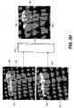
- FIGS. 2A , 2 B, 2 Cshow illustratively a typical reflectance image, a fluorescence image, and a FIRE image, respectively.
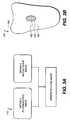
- FIG. 2Dis a view showing the process for combining dental image data to generate a FIRE image.
- FIG. 3Ashows an embodiment of a digital image generation step.
- FIG. 3Bshows a tooth region in a FIRE image having a lesion area identified in an extraction step.
- FIG. 3Cshows an embodiment of a step for extracting a lesion area from sound tooth regions according to the present invention.
- FIG. 3Dshows a FIRE image with a dilated line in a sound tooth area, and a lesion segmentation border separating a sound tooth area and a lesion area after a sound region identification step.
- FIG. 3Eshows an embodiment of an intensity reconstruction step using a bilinear interpolation.
- FIG. 4Ashows a binary image of three teeth.
- FIG. 4Bshows a contour line formed from a fan of ray lines from the origin point.
- FIG. 4Cshows determined internal and external markers.
- FIG. 4Dis an illustration of the marker-controlled watershed result.
- FIG. 4Eis an illustration of interlines between adjoining teeth.
- FIG. 5Ashows a binary image of three teeth similar to FIG. 4A .
- FIG. 5Bshows a distance image Idist formed from a distance transformation on the image of FIG. 5A .
- FIG. 5Cshows seed points in seeded areas.
- FIG. 5Dshows internal and external markers.
- FIG. 5Eis an illustration of interlines after the marker-controlled watershed and distance transform processing.
- FIG. 6Ashows a method for quantification of caries comprising a step of generating a FIRE image according to the present invention.
- FIG. 6Bshows a method for quantifying caries comprising a step of generating a FIRE image and sub-steps in step of extracting a lesion area from sound tooth regions according to the present invention.
- This inventionincludes calculation steps. Those skilled in the art will recognize that these calculation steps may be performed by data processing hardware that is provided with instructions for image data processing. Because such image manipulation systems are well known, the present description is directed more particularly to algorithms and systems that execute the method of the present invention. Other aspects of such algorithms and systems, and data processing hardware and/or software for producing and otherwise processing the image signals may be selected from such systems, algorithms, components and elements known in the art. Given the description as set forth in the following specification, software implementation lies within the ordinary skill of those versed in the programming arts.
- the stored instructions of such a software programmay be stored in a computer readable storage medium, which may comprise, for example: magnetic storage media such as a magnetic disk or magnetic tape; optical storage media such as an optical disc, optical tape, or machine readable bar code; solid state electronic storage devices such as random access memory (RAM), or read only memory (ROM); or any other physical device or medium employed to store a computer program.
- a computer readable storage mediumwhich may comprise, for example: magnetic storage media such as a magnetic disk or magnetic tape; optical storage media such as an optical disc, optical tape, or machine readable bar code; solid state electronic storage devices such as random access memory (RAM), or read only memory (ROM); or any other physical device or medium employed to store a computer program.
- RAMrandom access memory
- ROMread only memory
- the present inventioncan be utilized on a data processing hardware apparatus, such as a computer system or personal computer, or on an embedded system that employs a dedicated data processing component, such as a digital signal processing chip.
- the word “intensity”is used to refer to light level, and is also broadly used to refer to the value of a pixel in a digital image.
- water basinas used herein is a term of art used to describe a structure that is identified and used in executing a marker-controlled watershed transformation in the imaging arts.
- the term “catchment basin”is sometimes used in the same way. References in this disclosure to “water basin” refer to this imaging arts construct.
- a method for quantifying cariesexecuted at least in part on data processing hardware such as computer hardware, comprises a step 110 of generating a digital image of a tooth, the image comprising actual intensity values for a region of pixels corresponding to the tooth, gum, and background; a step 120 of extracting a lesion area from sound tooth regions by identifying tooth regions, extracting suspicious lesion areas, and removing false positives; a step 130 of identifying a sound region that is adjacent to the extracted lesion area; a step 140 of reconstructing intensity values for tooth tissue within the lesion area according to values in the adjacent sound region; and a step 150 of quantifying the condition of the caries using the reconstructed intensity values and intensity values from the lesion area.
- extracting a lesion areameans identifying at least one lesion area in a digital tooth image.
- FIGS. 2A , 2 B, and 2 Cshow illustratively a typical reflectance image 167 , a fluorescence image 168 , and a FIRE image 169 , respectively, of a tooth surface including a sound tooth area 164 and an early lesion area (or caries region) 162 .
- a reflectance imagesuch as a white light reflectance image
- the intensity of early caries regionsis higher than that of their surrounding sound areas.
- a fluorescence imagesuch as one obtained under blue excitation light
- the intensity of caries regionsis lower than that of their surrounding sound areas because of the fluorescence loss in caries regions.
- a FIRE imageis obtained through subtracting regional maxima and dome regions of the reflectance image from the fluorescence image.
- the FIRE imagehas a similar appearance as a fluorescence image because both have lower intensity values in a lesion area than in a surrounding sound area.
- the FIRE imagehas higher contrast than a fluorescence image, making it potentially more sensitive in detecting caries. It should be noted that other images that are generated by combining image data for the fluorescence and reflectance images can also be used for substituting the FIRE image.
- FIG. 2Dcorresponds to FIG. 5 of commonly-assigned copending U.S. Patent Application Publication No. 2008/0056551 (Wong et al.), entitled METHOD FOR DETECTION OF CARIES.
- This figureshows that a FIRE image 169 is formed by combining the fluorescence image 168 with the reflectance image 167 through a processing apparatus 180 .
- FIG. 3Ashows one embodiment of step 110 of generating a digital image of a tooth, comprising steps of obtaining a fluorescence image, obtaining a reflectance image, and combining image data for the fluorescence and reflectance images to generate an image such as a FIRE image. Details of how the fluorescence and reflectance images are obtained are described in U.S. Patent Application Publication No. 2008/0063998, published Mar. 13, 2008, entitled APPARATUS FOR CARIES DETECTION, by Liang et al.
- the digital image of the toothis a FIRE image 169 , which is formed by combining the fluorescence image 168 with the reflectance image 167 through a processing apparatus 180 as shown in FIG. 2D .
- the gray reflectance imagecan be the green channel of the reflectance image.
- the reflectance imageis a white light reflectance image.
- the white lightcan be emitted from one or more white LEDs.
- I markerI mask ⁇ h dome, where hdome, representing the height of a dome in the gray reflectance image, is a fixed value and is empirically selected based on the intensity values of a plurality of gray reflectance teeth images obtained. In one inventive example, hdome is 50.
- the generated FIRE imagecan be displayed as a color image by combining I FIRE with the red and blue channels of the fluorescence image.
- the fluorescence imageis one obtained under blue excitation light.
- the blue lightcan be emitted from one or more blue LEDs.
- the FIRE imageis the digital image used for subsequent image processing steps.
- step 110 of generating a digital image of a toothcomprises a step of obtaining a fluorescence image.
- the fluorescence imageis the digital image used for subsequent image processing steps.
- a digital image of a toothcan be classified into three groups of regions: 1) gum, 2) tooth, and 3) other background. Caries detection only needs to be performed inside tooth regions 165 .
- a lesion area 162inside the tooth region 165 is a lesion area 162 , a surrounding sound tooth area 164 , and segmentation border 163 that separates the two areas.
- segmentation border 163Methods for identifying tooth region 165 , lesion area 162 , surrounding sound tooth area 164 , and segmentation border 163 are described below.
- FIG. 3Cshows an embodiment of step 120 for extracting a lesion area 162 from tooth regions 165 in a digital image of a tooth according to the present invention.
- Step 120is performed automatically without a need for a user input.
- step 120includes sub-steps of identifying the tooth regions 165 , extracting one or more suspicious lesion areas, and removing false positives. These sub-steps include details specific to tooth images, as discussed below.
- Iwred, Iwgreen, Iwblue, Ibred, Ibgreen, Ibblue, Ifred, Ifgreen, and Ifblueare used to represent the intensity values of the pixels in the red, green, and blue channels of the reflectance, fluorescence, and FIRE images, respectively.
- intensity values of both reflectance and fluorescence imagesare adjusted to a range between 0 and 150, where 0 and 150 correspond to minimum and maximum intensity values.
- the FIRE imagehas higher green intensity values inside normal/sound tooth areas than in caries and other background areas. Consequently, an adapted threshold technique is preferably used on a fluorescence or FIRE image to separate the tooth region, which contains both normal/sound tooth areas and caries areas, from the gum and other background.
- tooth regions 165are identified from the digital tooth image as follows.
- grayscale versions of both the fluorescence and reflectance imagesare used, the grayscale images being generated from one channel of their respective color images, such as the green channel, or from a mixing of the three channels using methods well known in the image processing art.
- the embodimentis described below using the green channels of the fluorescence and reflectance images, Ibgreen and Iwgreen, respectively.
- Threshold imagesare generated from Ibgreen and Iwgreen by selecting intensity values higher than some predetermined threshold values c 1 and c 2 , for example, 10 and 30, respectively.
- the intersection regions of the two threshold imagesare taken as the preliminary tooth regions image Iroi 0 .
- a reference binary image Irefroiis obtained by thresholding the image Ibgreen with a threshold value c 3 higher than the one used in generating Iroi 0 , such as 30.
- a refined tooth regions 165 image, Iroiis generated by choosing the regions that are in Iroi 0 and connected to the objects in Irefroi. The above four steps increase the accuracy of selecting tooth regions 165 as compared to thresholding just the FIRE or fluorescence image.
- the refined tooth regions 165 imageis then used in the following sub-steps of extracting suspicious lesion areas and removing false positives.
- thresholding techniqueis applied to the fluorescence or FIRE image to determine tooth regions 165 . This embodiment helps to provide simpler and faster processing.
- a marker-controlled watershed based methodis adapted to detect and segment the suspicious caries areas.
- the key to this methodis to determine internal and external markers for the target objects.
- the internal markersare determined with the morphological grayscale reconstruction technique. The same technique has also been used for generating a FIRE image as discussed above.
- the regional basins Ihbasinare first detected; they correspond to the target regions of caries because they have lower intensity than surrounding sound areas. Then, the internal markers are obtained by thresholding Ihbasin with a fixed value, for example, 50. Note that the fixed value can be adjusted according to detection sensitivity requirement.
- the internal markersare the regions inside which the intensities of Ihbasin are higher than the given threshold value.
- a binary imageis first formed from the internal markers, wherein the pixel value of the binary image is 1 for a pixel inside internal markers and is 0 otherwise. Then a distance transformation (DT), mapping each image pixel onto its shortest distance to the target objects, is applied to the binary image to generate a DT image (see “Sequential operations in digital picture processing”, J. ACM. 13, 1966, by Rosenfeld, A. and Pfaltz, J. and “2D Euclidean distance transform algorithms: a comparative survey”, ACM computing surveys 40, 2008, by Ricardo Fabbri, Luciano Da F. Costa, Julio C. Torelli and Odemir M. Bruno). The ridge lines that are composed of the pixels with local maximal values in the DT image and located between the internal markers are taken as the external markers.
- DTdistance transformation
- the Sobel operatoris an image processing function well known to those skilled in the image processing/pattern recognition art; a description of it can be found in Pattern Classification and Scene Analysis , Duda, R. and Hart, P., John Wiley and Sons, 1973, pp.271-272.
- marker-controlled watershed transformationis then applied to generate a contour of the target regions of caries 162 directly.
- a description of the marker-controlled watershed transformationcan be found in “Morphological grayscale reconstruction in image analysis: applications and efficient algorithms”, IEEE Transaction on Image Processing, Vol. 2, pp. 176-201, 1993, by Luc Vincent.
- a method based on morphological bottom-hat operation along with the multi-resolution and surface reconstruction techniquesis adapted to detect and segment the suspicious caries areas.
- a bottom-hat operationis first applied to Ifgreen to produce an original bottom-hat image with an intensity value of Ibothat.
- a multi-resolution strategyis adapted to enable detection of caries with different sizes.
- the original bottom-hat imageis down-sampled to form one or more reduced-resolution bottom-hat images, such as 2 ⁇ -down sampled image and 4 ⁇ -down sampled image.
- the morphological bottom hatis then applied to the images with different resolutions (that is, original bottom-hat image, 2 ⁇ -down sampled bottom-hat image, 4 ⁇ -down sampled bottom-hat image, etc.).
- the 2-Dimensional structure elementcan take other shapes.
- the size of the structure elementfor example, the radius of the disk, can be adjusted according to the image resolution or the size of the target objects.
- the initial suspicious caries areasare usually not the optimal results.
- the target caries areascan be included inside the initial suspicious caries areas with high confidence.
- the weighting parameter wis 1.0, 0.5, and 0 for the original, 2 ⁇ -down sampled, and 4 ⁇ -down sampled images, respectively.
- the weighting parameter wcan be adjusted according to practical requirements.
- the normal intensity values (i.e., intensity values of the areas before the development of caries) inside the initial suspicious caries areascan be further estimated according to those outside the initial suspicious caries areas.
- the intensity estimationis a surface reconstruction processing, generating Ireconstructed, where intensity is taken as a topological surface. Subtracting the original image Ifgreen from the reconstructed image Ireconstructed, a difference image Idiff is obtained.
- the regions with larger change in intensity valuesare taken as the refined suspicious caries areas.
- the morphological grayscale reconstruction techniquecould also be used to detect regional maxima-dome of a certain height or regional minima-basin of a certain depth in a grayscale image, it is not as suitable as the embodiments discussed above to extract caries lesion in teeth image. This is because different caries areas have different contrast with respect to their surrounding areas. Thus, different regional extrema heights or depths are needed to suit different images or different caries infections. After all, the height or depth is still a global parameter. Additionally, the morphological grayscale reconstruction is more difficult to be implemented and is slower than the morphological bottom-hat method of the present invention.
- top/bottom hat methodmight also be considered for use to detect regional maxima dome or minima basin regions
- the methodalso is unsuitable in extracting caries lesion because it is difficult to determine the size of the structure element.
- Thisis unlike the morphological bottom-hat method of the present invention, which when used along with the multi-resolution and surface reconstruction techniques, successfully overcomes the problem of determining the size of the structure element.
- interproximal regionsareas having low contrast (typically lower than 7, though it can be adjusted according to the practical application) compared to the surrounding areas, and (2) areas between the proximal surfaces of adjoining teeth (hereafter referred to as interproximal regions).
- the low contrast false positivesare removed by calculating the intensity contrast between suspicious area and its surrounding area.
- the interproximal false positivesare removed according to the morphological features of the suspicious caries located inside or connected to the interproximal regions. To do this, the interproximal region is first identified.
- the interproximal regionscontain spaces that are part of the background.
- This first kind of interproximal region having clear demarcation of the adjoining teethis located as follows. Firstly, a distance transformation is applied to the binary image of tooth regions, and the pixel with the largest distance measured from the boundaries of the identified tooth regions in the binary image is located. Secondly, the identified tooth region that is connected to the located pixel is assigned as one object, and the other identified tooth regions are assigned as another object. And thirdly, the pixels in the background having the same distance to the two objects are then defined to be the interproximal regions.
- the interproximal regionsdo not contain a clear demarcation of the adjoining teeth.
- Different image processing approacheshave to be taken to identify this second kind of interproximal region in tooth images.
- the second kind of interproximal regionsare located in four steps with marker-controlled watershed transformation and distance transformation in the region connected to the pixel with the largest distance.
- FIG. 4Ashows a binary image of a target tooth 165 a and two neighboring teeth 165 b and 165 c .
- the light areasrepresent the teeth, while the dark areas represent background of the teeth.
- the light and dark areasare separated by a boundary.
- the origin point 200is defined as the pixel with the maximal distance to the boundaries of the teeth, though any point near the center of the target tooth 165 a can also be chosen as the origin point.
- the origin pointcan also be determined with other methods according to practical applications. For example, if the tooth located at the center of the image is chosen as the target tooth, the local maxima point closest to the image center can be selected as the origin point.
- a fan of ray lines 210are cast from the origin point 200 in every direction between 0° and 360°.
- a contour line 202is formed or defined from points at which each ray line 210 first encounters the boundary between the light and dark areas.
- internal and external markersare identified or determined as follows. As shown in FIG. 4C , internal makers are determined from a certain circular area 222 around the origin point 200 and the gray areas 220 a , 220 b , 220 c , 220 d . According to one example of the present invention, the radius of the circular area 222 is chosen as 3 ⁇ 4 times of the maximal distance, the distance of the origin point 200 to the tooth boundaries.
- the gray areas 220 a , 220 b , 220 c , 220 dare obtained by subtracting the area enclosed by the contour line 202 from the tooth areas 165 a , 165 b , 165 c , which have been determined by the boundary between the light and dark areas in reference to FIG. 4A .
- the outer light areas 224corresponding to the dark areas of FIG. 4A , are taken as the external markers.
- a marker-controlled watershed transformationis applied to a gradient image of a grayscale FIRE image with the above determined internal and external markers.
- the grayscale FIRE imageis generated from the green channel of the FIRE image, Ifgreen.
- the grayscale FIRE imagecan be generated from a mixing of the three channels using methods well known in the image processing art. This transformation results in a water basin 170 connected to the internal marker that corresponds to the circular area 222 of FIG. 4C , and water basins 172 a , 172 b , 172 c , 172 d connected to the internal markers that correspond to the gray areas 220 a , 220 b , 220 c and 220 d of FIG. 4C , respectively.
- Watershed line 173 aseparates water basins 172 a from 172 b
- watershed line 173 bseparates water basins 172 c from 172 d
- water basinalso referred to as catchment basin
- catchment basinis a term of the marker-controlled watershed transformation art in imaging, known to a person skilled in the art.
- FIG. 4Eshows parts of the interlines 176 , indicating locations of the interproximal regions that are identified.
- Interlines 176are obtained by marker-controlled watershed transformation and distance transformation.
- Region 174 ais obtained from water basin 170 .
- Region 174 bis obtained from a combination of water basins 172 a and 172 b .
- a region 174 cis obtained from a combination of water basins 172 c and 172 d.
- the second kind of interproximal regions that have no clear demarcationare located in four steps with a different adaptation of marker-controlled watershed transformation and distance transformation in the region connected to the pixel with the largest distance.
- this second inventive examplediffers from the first inventive example in the first two steps.
- FIG. 5Ashows a binary image of a target tooth 165 a and two neighboring teeth 165 b and 165 c .
- the light areasrepresent the teeth, while the dark areas represent background of the teeth.
- a distance transformationis applied to the image of FIG. 5A and results in a distance image Idist, in which the pixel value represents the closest distance of that pixel to the background of the teeth.
- the internal markers 230 a , 230 b , 230 c and external marker 232are determined as follows.
- Tdrecon>Tdreconrefers to the area in which the pixel values of Idrecon are greater than Tdrecon
- the symbol (Idist>Tdist)refers to the area in which the pixel values of Idist are greater than Tdrecon.
- the symbol ⁇is the intersection operator, familiar to those skilled in set theory.
- Seeded regions 230 a , 230 b , 230 c obtained from Iseedsare shown in FIG. 5C .
- a seed pointis identified as the pixel with maximal distance.
- seed points 234 a , 234 b , and 234 care the pixels having maximal distance in seeded areas 230 a , 230 b , and 230 c , respectively.
- a circular regionis created as an internal marker corresponding to the seed point.
- circular internal markers 236 a , 236 b , and 236 care created from seed points 234 a , 234 b , and 234 c , respectively, as shown in FIG. 5D .
- the background regions of the teethare used as the external markers 232 a , 232 b.
- marker-controlled watershed transformationis applied to the gradient image of a grayscale FIRE image with the above determined internal markers 236 a , 236 b , and 236 c and external markers 232 a , 232 b , and water basin regions 238 a , 238 b , 238 c for internal markers 236 a , 236 b , and 236 c are obtained, respectively.
- interlines 240 a , 240 bare located as the pixels having the same distance to two neighboring water basin regions.
- the suspicious caries areas connected to the interproximal regionsare then identified. Because some true caries are also located in these regions, not all the suspicious caries areas connected to the interproximal regions should be removed.
- a true cariesoften appears as a “grayscale hole”, which is an area of dark pixels surrounded by lighter pixels in the grayscale image.
- the “grayscale hole” characteristicis used to test which of the suspicious caries areas are true caries and should be retained, while the other suspicious areas connected to the interproximal regions are removed as false positives.
- the remaining suspicious caries areasare the extracted regions of caries 162 . These areas may be outlined or highlighted with false colors in a displayed FIRE, fluorescence, or reflectance image of the teeth to aid caries screening or diagnosis. They are also used for caries quantification analysis, in the steps described below.
- step 130 of identifying a sound tooth region adjacent to the extracted lesion areais performed by expanding the suspicious lesion areas 162 outward to dilated line 166 with morphological dilation, an operation well known in the image processing art.
- This stepis performed automatically without a need for user input.
- This step and steps 140 and 150are preferably performed on the fluorescence image, for reasons explained below.
- the areas surrounding the expanded suspicious lesion areasare taken as the normal/sound areas, and the values of the pixels making up the dilated line 166 are taken as the intensity values of the surrounding normal/sound areas.
- the algorithmic implementation of the morphological dilation stepis similar to that presented in FIG. 3 of commonly assigned co-pending U.S. Patent Application Publication No. 2008/0170764. This step reduces errors even if there are possible detection errors in the detected suspicious caries regions and in the non-significant intensity changes in normal/sound tooth areas.
- the reconstructed intensity value for tooth tissue within the lesion areacan be obtained using a bilinear interpolation technique according to values in the adjacent sound region as described below.
- FIG. 3Eshows an exploded view of a region of interest 161 shown in FIG. 3D .
- the estimation of the reconstructed intensity value I r at Pcan be calculated using a bilinear interpolation, for which the formulae are shown below.
- I HI L ⁇ x 2 + I R ⁇ x 1 x 2 + x 1
- Bilinear interpolationis carried out in this way for every pixel in the region of caries 162 to reconstruct the normal intensity values for the whole region.
- the reconstructed intensity value for tooth tissue within the lesion areacan be obtained using a surface fitting technique such as a two-dimensional spline, or Bézier fit.
- Another alternative embodiment for reconstructing intensity value for tooth tissue within the lesion areais to smoothly interpolate inward from the pixel's values on the boundaries of the expanded suspicious caries areas by solving Laplace's equation.
- This embodimentis an adaptation of a common image processing technique (such as what has been implemented in the familiar Matlab software function “roifill” in its image processing toolbox), and results in more accurate estimation.
- the condition of caries in a tooth imagecan be quantified in a number of ways, including calculating the size (or area) of the lesion area and calculating fluorescence loss ratio of the lesion area.
- the lesion areais calculated by counting the actual pixel number within the regions of caries 162 , and then converting that to actual spatial dimension, such as mm 2 .
- the fluorescence lossis used to measure the condition of the caries. Fluorescence loss in tooth structure has been demonstrated to be a direct indication of the degree of demineralization in the structure. This quantity can be directly calculated from the intensity values in the tooth's fluorescence image. In the fluorescence image, the fluorescence loss ratio ⁇ F at each pixel within the lesion area is calculated using the formula below:
- ⁇ ⁇ ⁇ FI r - I o I r , where I r is the reconstructed intensity value from step 140 , and I o is the actual measured intensity value of the green channel of the fluorescence image I FIuo . Where caries has occurred, ⁇ F>0.
- the whole fluorescence loss L of the lesion regionis the sum of ⁇ F within the lesion region R:
- FIG. 6Ashows a method for quantification of caries comprising a step of generating a FIRE image or other images obtained by combining a fluorescence image and a reflectance image of the tooth according to the present invention.
- FIG. 6Ais similar to FIG. 1 .
- the digital image of the toothis a FIRE image or the like which is generated from both a reflectance image and a fluorescence image.
- the reflectance imageis generated using white or single color light, while the fluorescence image is generated under excitation light in the ultraviolet-blue range.
- the fluorescence imagemay substitute the FIRE image as input, indicated by the dashed arrow 160 a .
- the fluorescence imageis also needed as input, indicated by the arrow 160 .
- FIG. 6Bshows another embodiment of the prevent invention. It is similar to FIG. 6A , but differs in step 120 which specifically comprises steps of identifying the tooth regions 165 from a tooth image, extracting a suspicious lesion area, and removing false positives.
- the dashed arrow 160 ashows that the fluorescence image may be used for step 130
- the arrow 160shows that the fluorescence image is used for steps 140 and 150 .
- the digital image generated in step 110is a fluorescence image of the tooth.
- the fluorescence imagehas similar characteristics as the FIRE image, and so the methods used in the lesion areas extraction step 120 can all be carried out on the fluorescence image. Therefore, in this alternative embodiment, the fluorescence image is used in all steps from Step 110 to Step 150 .
Landscapes
- Health & Medical Sciences (AREA)
- Engineering & Computer Science (AREA)
- Life Sciences & Earth Sciences (AREA)
- General Health & Medical Sciences (AREA)
- Physics & Mathematics (AREA)
- Medical Informatics (AREA)
- Public Health (AREA)
- Animal Behavior & Ethology (AREA)
- Veterinary Medicine (AREA)
- Biomedical Technology (AREA)
- Pathology (AREA)
- Heart & Thoracic Surgery (AREA)
- Molecular Biology (AREA)
- Biophysics (AREA)
- Surgery (AREA)
- Oral & Maxillofacial Surgery (AREA)
- Dentistry (AREA)
- General Physics & Mathematics (AREA)
- Theoretical Computer Science (AREA)
- Computer Vision & Pattern Recognition (AREA)
- Quality & Reliability (AREA)
- Radiology & Medical Imaging (AREA)
- Nuclear Medicine, Radiotherapy & Molecular Imaging (AREA)
- Audiology, Speech & Language Pathology (AREA)
- Epidemiology (AREA)
- Human Computer Interaction (AREA)
- Orthopedic Medicine & Surgery (AREA)
- Rheumatology (AREA)
- Physical Education & Sports Medicine (AREA)
- Investigating, Analyzing Materials By Fluorescence Or Luminescence (AREA)
- Dental Tools And Instruments Or Auxiliary Dental Instruments (AREA)
- Endoscopes (AREA)
- Investigating Or Analysing Materials By Optical Means (AREA)
- Image Analysis (AREA)
- Image Processing (AREA)
- Investigating Or Analysing Biological Materials (AREA)
Abstract
Description
Imarker=Imask−hdome,
where hdome, representing the height of a dome in the gray reflectance image, is a fixed value and is empirically selected based on the intensity values of a plurality of gray reflectance teeth images obtained. In one inventive example, hdome is 50.
Ihdome=Imask−Ireconstructed.
IFIRE=IFluo−Ihdome,
where IFIREand IFluoare the intensity values of the green channel of the generated FIRE image and the obtained fluorescence image, respectively. The generated FIRE image can be displayed as a color image by combining IFIREwith the red and blue channels of the fluorescence image. In one example, the fluorescence image is one obtained under blue excitation light. The blue light can be emitted from one or more blue LEDs. The FIRE image is the digital image used for subsequent image processing steps.
Ithres=Imean+w*Istd,
where w is the weighting parameter determined experimentally, and Imean and Istd are the mean and standard deviation of intensity values, respectively. Applying a threshold operation to each of the multi-resolution bottom-hat images, a binary image is obtained, inside which the regions with a nonzero value are the initial suspicious caries areas in the image with corresponding resolution. After interpolating each of the binary images back to the original resolution to produce interpolated images, the union of all the interpolated images is taken as the initial suspicious lesion areas.
Iseeds=(Idrecon>Tdrecon)∩(Idist>Tdist),
where Tdrecon and Tdist are two threshold values (for example, Tdrecon=5, and Tdist=10), respectively. The symbol (Idrecon>Tdrecon) refers to the area in which the pixel values of Idrecon are greater than Tdrecon, and the symbol (Idist>Tdist) refers to the area in which the pixel values of Idist are greater than Tdrecon. The symbol ∩ is the intersection operator, familiar to those skilled in set theory.
where Iris the reconstructed intensity value from
- 110 step of generating a digital image of a tooth
- 120 step of extracting a lesion area from sound tooth regions
- 130 step of identifying a sound region adjacent to the extracted lesion area
- 140 step of reconstructing intensity values for tooth tissue within the lesion area
- 150 step of calculating the condition of the caries
- 160,160aarrow
- 161 region of interest
- 162 lesion area (or region of caries)
- 163 segmentation border
- 164 sound tooth area
- 165 tooth region
- 165a,165b,165ctooth
- 166 dilated line
- 167 reflectance image
- 168 fluorescence image
- 169 FIRE image
- 170 water basin corresponding to the circular
internal marker area 222 - 172a,172b,172c,172dwater basins
- 173a,173bwatershed lines
- 174aregion corresponding to
water basin 170 - 174bregion corresponding to a combination of
water basins - 174cregion corresponding to a combination of
water basins - 176 interlines between teeth
- 180 processing apparatus
- 200 origin point
- 202 contour line
- 210 ray lines
- 220a,220b,220c,220dgray areas corresponding to internal markers
- 222 circular area on the target tooth corresponding to internal markers
- 224 light areas corresponding to an external marker
- 230a,230b,230cseeded areas
- 232a,232bexternal markers
- 234a,234b,234cseed points
- 236a,236b,236cinternal markers
- 238a,236b,236cwater basin regions
- 240a,240binterlines
Claims (23)
Priority Applications (7)
| Application Number | Priority Date | Filing Date | Title |
|---|---|---|---|
| US12/487,729US8768016B2 (en) | 2009-06-19 | 2009-06-19 | Method for quantifying caries |
| JP2010127725AJP5729924B2 (en) | 2009-06-19 | 2010-06-03 | Caries determination method |
| EP10006356AEP2312527A3 (en) | 2009-06-19 | 2010-06-18 | Method for quantifying caries |
| KR1020100058206AKR101646792B1 (en) | 2009-06-19 | 2010-06-18 | Method for quantifying caries |
| CN201611034037.1ACN106898013A (en) | 2009-06-19 | 2010-06-18 | The method of quantifying caries |
| CN201010211688XACN101926641A (en) | 2009-06-19 | 2010-06-18 | Method for quantifying dental caries |
| US14/197,637US9773306B2 (en) | 2009-06-19 | 2014-03-05 | Method for quantifying caries |
Applications Claiming Priority (1)
| Application Number | Priority Date | Filing Date | Title |
|---|---|---|---|
| US12/487,729US8768016B2 (en) | 2009-06-19 | 2009-06-19 | Method for quantifying caries |
Related Child Applications (1)
| Application Number | Title | Priority Date | Filing Date |
|---|---|---|---|
| US14/197,637ContinuationUS9773306B2 (en) | 2009-06-19 | 2014-03-05 | Method for quantifying caries |
Publications (2)
| Publication Number | Publication Date |
|---|---|
| US20100322490A1 US20100322490A1 (en) | 2010-12-23 |
| US8768016B2true US8768016B2 (en) | 2014-07-01 |
Family
ID=42702031
Family Applications (2)
| Application Number | Title | Priority Date | Filing Date |
|---|---|---|---|
| US12/487,729Active2032-09-17US8768016B2 (en) | 2009-06-19 | 2009-06-19 | Method for quantifying caries |
| US14/197,637Active2029-08-06US9773306B2 (en) | 2009-06-19 | 2014-03-05 | Method for quantifying caries |
Family Applications After (1)
| Application Number | Title | Priority Date | Filing Date |
|---|---|---|---|
| US14/197,637Active2029-08-06US9773306B2 (en) | 2009-06-19 | 2014-03-05 | Method for quantifying caries |
Country Status (5)
| Country | Link |
|---|---|
| US (2) | US8768016B2 (en) |
| EP (1) | EP2312527A3 (en) |
| JP (1) | JP5729924B2 (en) |
| KR (1) | KR101646792B1 (en) |
| CN (2) | CN101926641A (en) |
Cited By (62)
| Publication number | Priority date | Publication date | Assignee | Title |
|---|---|---|---|---|
| US20150164335A1 (en)* | 2012-06-27 | 2015-06-18 | 3Shape A/S | 3d intraoral scanner measuring fluorescence |
| US9547903B2 (en) | 2015-04-16 | 2017-01-17 | Carestream Health, Inc. | Method for quantifying caries |
| US10123706B2 (en) | 2016-07-27 | 2018-11-13 | Align Technology, Inc. | Intraoral scanner with dental diagnostics capabilities |
| US10130445B2 (en) | 2014-09-19 | 2018-11-20 | Align Technology, Inc. | Arch expanding appliance |
| US10248883B2 (en) | 2015-08-20 | 2019-04-02 | Align Technology, Inc. | Photograph-based assessment of dental treatments and procedures |
| US10327872B2 (en) | 2014-08-15 | 2019-06-25 | Align Technology, Inc. | Field curvature model for confocal imaging apparatus with curved focal surface |
| US10383705B2 (en) | 2016-06-17 | 2019-08-20 | Align Technology, Inc. | Orthodontic appliance performance monitor |
| US10390913B2 (en) | 2018-01-26 | 2019-08-27 | Align Technology, Inc. | Diagnostic intraoral scanning |
| US10421152B2 (en) | 2011-09-21 | 2019-09-24 | Align Technology, Inc. | Laser cutting |
| US10449016B2 (en) | 2014-09-19 | 2019-10-22 | Align Technology, Inc. | Arch adjustment appliance |
| US10456043B2 (en) | 2017-01-12 | 2019-10-29 | Align Technology, Inc. | Compact confocal dental scanning apparatus |
| US10470847B2 (en) | 2016-06-17 | 2019-11-12 | Align Technology, Inc. | Intraoral appliances with sensing |
| US10504386B2 (en) | 2015-01-27 | 2019-12-10 | Align Technology, Inc. | Training method and system for oral-cavity-imaging-and-modeling equipment |
| US10507087B2 (en) | 2016-07-27 | 2019-12-17 | Align Technology, Inc. | Methods and apparatuses for forming a three-dimensional volumetric model of a subject's teeth |
| US10517482B2 (en) | 2017-07-27 | 2019-12-31 | Align Technology, Inc. | Optical coherence tomography for orthodontic aligners |
| US10524881B2 (en) | 2010-04-30 | 2020-01-07 | Align Technology, Inc. | Patterned dental positioning appliance |
| US10537405B2 (en) | 2014-11-13 | 2020-01-21 | Align Technology, Inc. | Dental appliance with cavity for an unerupted or erupting tooth |
| US10548700B2 (en) | 2016-12-16 | 2020-02-04 | Align Technology, Inc. | Dental appliance etch template |
| US10595966B2 (en) | 2016-11-04 | 2020-03-24 | Align Technology, Inc. | Methods and apparatuses for dental images |
| US10613515B2 (en) | 2017-03-31 | 2020-04-07 | Align Technology, Inc. | Orthodontic appliances including at least partially un-erupted teeth and method of forming them |
| US10610332B2 (en) | 2012-05-22 | 2020-04-07 | Align Technology, Inc. | Adjustment of tooth position in a virtual dental model |
| US10639134B2 (en) | 2017-06-26 | 2020-05-05 | Align Technology, Inc. | Biosensor performance indicator for intraoral appliances |
| US10772506B2 (en) | 2014-07-07 | 2020-09-15 | Align Technology, Inc. | Apparatus for dental confocal imaging |
| US10779718B2 (en) | 2017-02-13 | 2020-09-22 | Align Technology, Inc. | Cheek retractor and mobile device holder |
| US10813720B2 (en) | 2017-10-05 | 2020-10-27 | Align Technology, Inc. | Interproximal reduction templates |
| US10885521B2 (en) | 2017-07-17 | 2021-01-05 | Align Technology, Inc. | Method and apparatuses for interactive ordering of dental aligners |
| US10893918B2 (en) | 2012-03-01 | 2021-01-19 | Align Technology, Inc. | Determining a dental treatment difficulty |
| US10919209B2 (en) | 2009-08-13 | 2021-02-16 | Align Technology, Inc. | Method of forming a dental appliance |
| US10937108B1 (en) | 2020-01-17 | 2021-03-02 | Pearl Inc. | Computer vision-based claims processing |
| US20210073977A1 (en)* | 2019-09-05 | 2021-03-11 | Pearl Inc. | Systems and methods for automated medical image annotation |
| US10980613B2 (en) | 2017-12-29 | 2021-04-20 | Align Technology, Inc. | Augmented reality enhancements for dental practitioners |
| US10993783B2 (en) | 2016-12-02 | 2021-05-04 | Align Technology, Inc. | Methods and apparatuses for customizing a rapid palatal expander |
| US11026831B2 (en) | 2016-12-02 | 2021-06-08 | Align Technology, Inc. | Dental appliance features for speech enhancement |
| US11045283B2 (en) | 2017-06-09 | 2021-06-29 | Align Technology, Inc. | Palatal expander with skeletal anchorage devices |
| US11096763B2 (en) | 2017-11-01 | 2021-08-24 | Align Technology, Inc. | Automatic treatment planning |
| US11103330B2 (en) | 2015-12-09 | 2021-08-31 | Align Technology, Inc. | Dental attachment placement structure |
| US11116605B2 (en) | 2017-08-15 | 2021-09-14 | Align Technology, Inc. | Buccal corridor assessment and computation |
| US11123156B2 (en) | 2017-08-17 | 2021-09-21 | Align Technology, Inc. | Dental appliance compliance monitoring |
| US11219506B2 (en) | 2017-11-30 | 2022-01-11 | Align Technology, Inc. | Sensors for monitoring oral appliances |
| US11273011B2 (en) | 2016-12-02 | 2022-03-15 | Align Technology, Inc. | Palatal expanders and methods of expanding a palate |
| US11376101B2 (en) | 2016-12-02 | 2022-07-05 | Align Technology, Inc. | Force control, stop mechanism, regulating structure of removable arch adjustment appliance |
| US11389131B2 (en) | 2018-06-27 | 2022-07-19 | Denti.Ai Technology Inc. | Systems and methods for processing of dental images |
| US11419702B2 (en) | 2017-07-21 | 2022-08-23 | Align Technology, Inc. | Palatal contour anchorage |
| US11426259B2 (en) | 2012-02-02 | 2022-08-30 | Align Technology, Inc. | Identifying forces on a tooth |
| US11432908B2 (en) | 2017-12-15 | 2022-09-06 | Align Technology, Inc. | Closed loop adaptive orthodontic treatment methods and apparatuses |
| US11534268B2 (en) | 2017-10-27 | 2022-12-27 | Align Technology, Inc. | Alternative bite adjustment structures |
| US11534974B2 (en) | 2017-11-17 | 2022-12-27 | Align Technology, Inc. | Customized fabrication of orthodontic retainers based on patient anatomy |
| US11554000B2 (en) | 2015-11-12 | 2023-01-17 | Align Technology, Inc. | Dental attachment formation structure |
| US11564777B2 (en) | 2018-04-11 | 2023-01-31 | Align Technology, Inc. | Releasable palatal expanders |
| US11576752B2 (en) | 2017-10-31 | 2023-02-14 | Align Technology, Inc. | Dental appliance having selective occlusal loading and controlled intercuspation |
| US11596502B2 (en) | 2015-12-09 | 2023-03-07 | Align Technology, Inc. | Dental attachment placement structure |
| US11612454B2 (en) | 2010-04-30 | 2023-03-28 | Align Technology, Inc. | Individualized orthodontic treatment index |
| US11633268B2 (en) | 2017-07-27 | 2023-04-25 | Align Technology, Inc. | Tooth shading, transparency and glazing |
| US11653838B2 (en)* | 2020-03-11 | 2023-05-23 | Alireza Moheb | System and method for classification of dental health based on digital imagery |
| US11676701B2 (en) | 2019-09-05 | 2023-06-13 | Pearl Inc. | Systems and methods for automated medical image analysis |
| US11776677B2 (en) | 2021-01-06 | 2023-10-03 | Pearl Inc. | Computer vision-based analysis of provider data |
| US11931222B2 (en) | 2015-11-12 | 2024-03-19 | Align Technology, Inc. | Dental attachment formation structures |
| US11937991B2 (en) | 2018-03-27 | 2024-03-26 | Align Technology, Inc. | Dental attachment placement structure |
| US11996181B2 (en) | 2017-06-16 | 2024-05-28 | Align Technology, Inc. | Automatic detection of tooth type and eruption status |
| US12090020B2 (en) | 2017-03-27 | 2024-09-17 | Align Technology, Inc. | Apparatuses and methods assisting in dental therapies |
| US12171575B2 (en) | 2017-10-04 | 2024-12-24 | Align Technology, Inc. | Intraoral systems and methods for sampling soft-tissue |
| US12274597B2 (en) | 2017-08-11 | 2025-04-15 | Align Technology, Inc. | Dental attachment template tray systems |
Families Citing this family (32)
| Publication number | Priority date | Publication date | Assignee | Title |
|---|---|---|---|---|
| US7259906B1 (en) | 2002-09-03 | 2007-08-21 | Cheetah Omni, Llc | System and method for voice control of medical devices |
| US7519253B2 (en) | 2005-11-18 | 2009-04-14 | Omni Sciences, Inc. | Broadband or mid-infrared fiber light sources |
| US8768016B2 (en) | 2009-06-19 | 2014-07-01 | Carestream Health, Inc. | Method for quantifying caries |
| US8687859B2 (en)* | 2009-10-14 | 2014-04-01 | Carestream Health, Inc. | Method for identifying a tooth region |
| US9235901B2 (en)* | 2009-10-14 | 2016-01-12 | Carestream Health, Inc. | Method for locating an interproximal tooth region |
| US8908936B2 (en)* | 2009-10-14 | 2014-12-09 | Carestream Health, Inc. | Method for extracting a carious lesion area |
| TWI435704B (en)* | 2011-03-15 | 2014-05-01 | Crystalvue Medical Corp | Oral optical diagnosing apparatus and operating method thereof |
| WO2012129160A2 (en)* | 2011-03-21 | 2012-09-27 | Carestream Health, Inc. | A method for tooth surface classification |
| WO2012173976A2 (en) | 2011-06-17 | 2012-12-20 | Carroll Robert G | Methods and apparatus for assessing activity of an organ and uses thereof |
| US9486141B2 (en) | 2011-08-09 | 2016-11-08 | Carestream Health, Inc. | Identification of dental caries in live video images |
| CN104303184B (en)* | 2012-03-21 | 2018-05-15 | 皇家飞利浦有限公司 | Clinical workstation integrating medical imaging and biopsy data and method of using same |
| US12193790B2 (en) | 2012-12-31 | 2025-01-14 | Omni Medsci, Inc. | Wearable devices comprising semiconductor diode light sources with improved signal-to-noise ratio |
| EP2938259A4 (en) | 2012-12-31 | 2016-08-17 | Omni Medsci Inc | Near-infrared lasers for non-invasive monitoring of glucose, ketones, hba1c, and other blood constituents |
| US9500634B2 (en) | 2012-12-31 | 2016-11-22 | Omni Medsci, Inc. | Short-wave infrared super-continuum lasers for natural gas leak detection, exploration, and other active remote sensing applications |
| WO2014143276A2 (en) | 2012-12-31 | 2014-09-18 | Omni Medsci, Inc. | Short-wave infrared super-continuum lasers for natural gas leak detection, exploration, and other active remote sensing applications |
| US10660526B2 (en) | 2012-12-31 | 2020-05-26 | Omni Medsci, Inc. | Near-infrared time-of-flight imaging using laser diodes with Bragg reflectors |
| CA2895982A1 (en) | 2012-12-31 | 2014-07-03 | Omni Medsci, Inc. | Short-wave infrared super-continuum lasers for early detection of dental caries |
| US9993159B2 (en) | 2012-12-31 | 2018-06-12 | Omni Medsci, Inc. | Near-infrared super-continuum lasers for early detection of breast and other cancers |
| US9870613B2 (en)* | 2014-11-05 | 2018-01-16 | Carestream Health, Inc. | Detection of tooth condition using reflectance images with red and green fluorescence |
| CN104574411A (en)* | 2015-01-22 | 2015-04-29 | 北京交通大学 | Dental caries image processing method based on extracted tooth CBCT |
| US10198819B2 (en)* | 2015-11-30 | 2019-02-05 | Snap Inc. | Image segmentation and modification of a video stream |
| KR20190007451A (en) | 2016-05-10 | 2019-01-22 | 마사키 캄바라 | Dental health judgment support device and tooth health judgment support system |
| JP2018022260A (en)* | 2016-08-02 | 2018-02-08 | 株式会社オプテック | Image processor |
| KR102329680B1 (en)* | 2017-03-24 | 2021-11-23 | 삼성메디슨 주식회사 | Method and apparatus for displaying medical images |
| CN110913956A (en)* | 2017-04-24 | 2020-03-24 | 高露洁-棕榄公司 | Method for monitoring white spots on teeth |
| TWI633875B (en)* | 2017-09-15 | 2018-09-01 | 霽邦有限公司 | Method and system for manufacturing apical resection surgery guide plate and computer-readable recording medium |
| CN114283105A (en)* | 2020-09-18 | 2022-04-05 | 强生(中国)有限公司 | Oral detection method, oral detection device, and computer-readable storage medium |
| KR102442719B1 (en)* | 2020-10-22 | 2022-09-13 | 주식회사 메디트 | Image processing method and image processing apparatus using same |
| CN112914484A (en)* | 2021-03-03 | 2021-06-08 | 清华大学深圳国际研究生院 | Endoscopic detection device of tooth of intelligence |
| TWI818372B (en)* | 2021-12-03 | 2023-10-11 | 財團法人金屬工業研究發展中心 | Oral cavity detecting system |
| TWI769966B (en)* | 2022-01-05 | 2022-07-01 | 中山醫學大學 | Auxiliary methods for caries detection |
| CN118314143A (en)* | 2024-06-11 | 2024-07-09 | 成都玻尔兹曼智贝科技有限公司 | Tooth early enamel demineralization evaluation method and device based on artificial intelligence |
Citations (32)
| Publication number | Priority date | Publication date | Assignee | Title |
|---|---|---|---|---|
| US4479499A (en) | 1982-01-29 | 1984-10-30 | Alfano Robert R | Method and apparatus for detecting the presence of caries in teeth using visible light |
| US4515476A (en) | 1981-04-01 | 1985-05-07 | Bjelkhagen Hans Ingmar | Device for the ocular determination of any discrepancy in the luminescence capacity of the surface of a tooth for the purpose of identifying any caried area on the surface to the tooth |
| US4941164A (en) | 1987-10-29 | 1990-07-10 | The Governors Of The University Of Alberta | Method and apparatus for improving the alignment of radiographic images |
| US6231338B1 (en)* | 1999-05-10 | 2001-05-15 | Inspektor Research Systems B.V. | Method and apparatus for the detection of carious activity of a carious lesion in a tooth |
| US20040184643A1 (en) | 2003-03-21 | 2004-09-23 | Stantchev Gueorgui H. | Methods and apparatus for imaging |
| US20040202356A1 (en) | 2003-04-10 | 2004-10-14 | Stookey George K. | Optical detection of dental caries |
| US20040240716A1 (en)* | 2003-05-22 | 2004-12-02 | De Josselin De Jong Elbert | Analysis and display of fluorescence images |
| US20050010106A1 (en)* | 2003-03-25 | 2005-01-13 | Imaging Therapeutics, Inc. | Methods for the compensation of imaging technique in the processing of radiographic images |
| US20050244794A1 (en) | 2004-04-30 | 2005-11-03 | Kemp James H | Computer-implemented system and method for automated and highly accurate plaque analysis, reporting, and visualization |
| US20050283058A1 (en) | 2004-06-09 | 2005-12-22 | Choo-Smith Lin-P Ing | Detection and monitoring of changes in mineralized tissues or calcified deposits by optical coherence tomography and Raman spectroscopy |
| US20060239526A1 (en)* | 2003-06-17 | 2006-10-26 | Centre National De La Recherche Scientifique | Method and apparatus for acquiring and processing images of an article such as a tooth |
| US20070021670A1 (en) | 2005-07-18 | 2007-01-25 | Andreas Mandelis | Method and apparatus using infrared photothermal radiometry (PTR) and modulated laser luminescence (LUM) for diagnostics of defects in teeth |
| US20070019858A1 (en) | 2005-07-22 | 2007-01-25 | Hitachi High-Technologies Corporation | Method and apparatus for visual inspection |
| US7179066B2 (en)* | 2003-08-13 | 2007-02-20 | Ti Group Automotive Systems, L.L.C. | Electric motor fuel pump |
| US20070053491A1 (en) | 2005-09-07 | 2007-03-08 | Eastman Kodak Company | Adaptive radiation therapy method with target detection |
| US20070081718A1 (en) | 2000-04-28 | 2007-04-12 | Rudger Rubbert | Methods for registration of three-dimensional frames to create three-dimensional virtual models of objects |
| US20070099148A1 (en) | 2005-10-31 | 2007-05-03 | Eastman Kodak Company | Method and apparatus for detection of caries |
| US7270543B2 (en)* | 2004-06-29 | 2007-09-18 | Therametric Technologies, Inc. | Handpiece for caries detection |
| US20070248931A1 (en)* | 2006-04-21 | 2007-10-25 | Eastman Kodak Company | Optical detection of dental caries |
| US7305111B2 (en)* | 2004-01-30 | 2007-12-04 | University Of Chicago | Automated method and system for the detection of lung nodules in low-dose CT images for lung-cancer screening |
| WO2008027323A2 (en) | 2006-08-31 | 2008-03-06 | Carestream Health, Inc. | Method for detection of caries |
| US20080062429A1 (en) | 2006-09-12 | 2008-03-13 | Rongguang Liang | Low coherence dental oct imaging |
| US20080063998A1 (en) | 2006-09-12 | 2008-03-13 | Rongguang Liang | Apparatus for caries detection |
| US20080170764A1 (en) | 2007-01-17 | 2008-07-17 | Burns Peter D | System for early detection of dental caries |
| EP2083389A2 (en) | 2008-01-22 | 2009-07-29 | Carestream Health, Inc. | Method for a real-time visualization of caries condition |
| US20090238457A1 (en) | 2008-03-21 | 2009-09-24 | General Electric Company | Methods and systems for automated segmentation of dense cell populations |
| WO2010083623A1 (en) | 2009-01-20 | 2010-07-29 | Carestream Health, Inc. | Method and apparatus for detection of caries |
| US20100322490A1 (en) | 2009-06-19 | 2010-12-23 | Liangliang Pan | Method for quantifying caries |
| US20110085715A1 (en)* | 2009-10-14 | 2011-04-14 | Jiayong Yan | Method for locating an interproximal tooth region |
| US20110085714A1 (en)* | 2009-10-14 | 2011-04-14 | Jiayong Yan | Method for extracting a carious lesion area |
| US20120148986A1 (en)* | 2010-12-13 | 2012-06-14 | Jiayong Yan | Method for identification of dental caries in polychromatic images |
| US8447087B2 (en)* | 2006-09-12 | 2013-05-21 | Carestream Health, Inc. | Apparatus and method for caries detection |
Family Cites Families (21)
| Publication number | Priority date | Publication date | Assignee | Title |
|---|---|---|---|---|
| JP4338425B2 (en)* | 2003-04-16 | 2009-10-07 | 花王株式会社 | Caries detection device and cavities detection program for realizing the same |
| JP2005118197A (en)* | 2003-10-15 | 2005-05-12 | Matsushita Electric Ind Co Ltd | Caries detection device |
| KR100800120B1 (en)* | 2003-12-08 | 2008-02-01 | 가부시끼가이샤 모리다 세이사꾸쇼 | Dental medical examination device |
| CN1556502A (en)* | 2004-01-08 | 2004-12-22 | 上海交通大学 | Dynamic Image Sequence Segmentation Method |
| US7327880B2 (en) | 2004-03-12 | 2008-02-05 | Siemens Medical Solutions Usa, Inc. | Local watershed operators for image segmentation |
| US7698068B2 (en)* | 2004-06-17 | 2010-04-13 | Cadent Ltd. | Method for providing data associated with the intraoral cavity |
| ES2405829T3 (en)* | 2004-08-13 | 2013-06-04 | Biolase, Inc. | Caries detection using time differentials between excitation and return impulses |
| JP2006122335A (en)* | 2004-10-28 | 2006-05-18 | Morita Mfg Co Ltd | Camera device |
| US7773787B2 (en) | 2005-04-19 | 2010-08-10 | Siemens Medical Solutions Usa, Inc. | Method and apparatus for detecting blood vessel boundaries using multi-scale mean-shift ray propagation |
| JP2006325640A (en)* | 2005-05-23 | 2006-12-07 | Konica Minolta Medical & Graphic Inc | Method of displaying abnormal shadow candidate and medical image processing system |
| DE102005058217B4 (en)* | 2005-12-06 | 2013-06-06 | Siemens Aktiengesellschaft | Method and system for computer-aided detection of high-contrast objects in tomographic images |
| US20080038686A1 (en)* | 2006-04-18 | 2008-02-14 | Shigemi Nagai | Methods and kits for early stage caries detection |
| US7702139B2 (en)* | 2006-10-13 | 2010-04-20 | Carestream Health, Inc. | Apparatus for caries detection |
| CN100562291C (en)* | 2006-11-08 | 2009-11-25 | 沈阳东软医疗系统有限公司 | A processing device, method and system for CT images |
| US9305334B2 (en)* | 2007-03-08 | 2016-04-05 | Sync-Rx, Ltd. | Luminal background cleaning |
| US20090082695A1 (en) | 2007-06-25 | 2009-03-26 | Led Medical Diagnostics, Inc. | Methods, systems and apparatus relating to colposcopic-type viewing extension devices |
| US9095313B2 (en)* | 2008-11-18 | 2015-08-04 | Sync-Rx, Ltd. | Accounting for non-uniform longitudinal motion during movement of an endoluminal imaging probe |
| US8687859B2 (en)* | 2009-10-14 | 2014-04-01 | Carestream Health, Inc. | Method for identifying a tooth region |
| WO2012129160A2 (en)* | 2011-03-21 | 2012-09-27 | Carestream Health, Inc. | A method for tooth surface classification |
| US9486141B2 (en)* | 2011-08-09 | 2016-11-08 | Carestream Health, Inc. | Identification of dental caries in live video images |
| DK2956084T3 (en)* | 2013-02-13 | 2022-10-31 | 3Shape As | FOCUS SCANNING DEVICE FOR REGISTERING COLOR |
- 2009
- 2009-06-19USUS12/487,729patent/US8768016B2/enactiveActive
- 2010
- 2010-06-03JPJP2010127725Apatent/JP5729924B2/ennot_activeExpired - Fee Related
- 2010-06-18EPEP10006356Apatent/EP2312527A3/ennot_activeWithdrawn
- 2010-06-18CNCN201010211688XApatent/CN101926641A/enactivePending
- 2010-06-18CNCN201611034037.1Apatent/CN106898013A/enactivePending
- 2010-06-18KRKR1020100058206Apatent/KR101646792B1/ennot_activeExpired - Fee Related
- 2014
- 2014-03-05USUS14/197,637patent/US9773306B2/enactiveActive
Patent Citations (37)
| Publication number | Priority date | Publication date | Assignee | Title |
|---|---|---|---|---|
| US4515476A (en) | 1981-04-01 | 1985-05-07 | Bjelkhagen Hans Ingmar | Device for the ocular determination of any discrepancy in the luminescence capacity of the surface of a tooth for the purpose of identifying any caried area on the surface to the tooth |
| US4479499A (en) | 1982-01-29 | 1984-10-30 | Alfano Robert R | Method and apparatus for detecting the presence of caries in teeth using visible light |
| US4941164A (en) | 1987-10-29 | 1990-07-10 | The Governors Of The University Of Alberta | Method and apparatus for improving the alignment of radiographic images |
| US6231338B1 (en)* | 1999-05-10 | 2001-05-15 | Inspektor Research Systems B.V. | Method and apparatus for the detection of carious activity of a carious lesion in a tooth |
| US20070081718A1 (en) | 2000-04-28 | 2007-04-12 | Rudger Rubbert | Methods for registration of three-dimensional frames to create three-dimensional virtual models of objects |
| US20040184643A1 (en) | 2003-03-21 | 2004-09-23 | Stantchev Gueorgui H. | Methods and apparatus for imaging |
| US20050010106A1 (en)* | 2003-03-25 | 2005-01-13 | Imaging Therapeutics, Inc. | Methods for the compensation of imaging technique in the processing of radiographic images |
| US20040202356A1 (en) | 2003-04-10 | 2004-10-14 | Stookey George K. | Optical detection of dental caries |
| US20040240716A1 (en)* | 2003-05-22 | 2004-12-02 | De Josselin De Jong Elbert | Analysis and display of fluorescence images |
| WO2004104927A2 (en) | 2003-05-22 | 2004-12-02 | Inspektor Research Systems B.V. | Analysis and display of fluorescence images |
| US20060239526A1 (en)* | 2003-06-17 | 2006-10-26 | Centre National De La Recherche Scientifique | Method and apparatus for acquiring and processing images of an article such as a tooth |
| US7179066B2 (en)* | 2003-08-13 | 2007-02-20 | Ti Group Automotive Systems, L.L.C. | Electric motor fuel pump |
| US7305111B2 (en)* | 2004-01-30 | 2007-12-04 | University Of Chicago | Automated method and system for the detection of lung nodules in low-dose CT images for lung-cancer screening |
| US20050244794A1 (en) | 2004-04-30 | 2005-11-03 | Kemp James H | Computer-implemented system and method for automated and highly accurate plaque analysis, reporting, and visualization |
| US20050283058A1 (en) | 2004-06-09 | 2005-12-22 | Choo-Smith Lin-P Ing | Detection and monitoring of changes in mineralized tissues or calcified deposits by optical coherence tomography and Raman spectroscopy |
| US7270543B2 (en)* | 2004-06-29 | 2007-09-18 | Therametric Technologies, Inc. | Handpiece for caries detection |
| US20070021670A1 (en) | 2005-07-18 | 2007-01-25 | Andreas Mandelis | Method and apparatus using infrared photothermal radiometry (PTR) and modulated laser luminescence (LUM) for diagnostics of defects in teeth |
| US8131058B2 (en)* | 2005-07-22 | 2012-03-06 | Hitachi High-Technologies Corporation | Method and apparatus for visual inspection |
| US20070019858A1 (en) | 2005-07-22 | 2007-01-25 | Hitachi High-Technologies Corporation | Method and apparatus for visual inspection |
| US20070053491A1 (en) | 2005-09-07 | 2007-03-08 | Eastman Kodak Company | Adaptive radiation therapy method with target detection |
| US20070099148A1 (en) | 2005-10-31 | 2007-05-03 | Eastman Kodak Company | Method and apparatus for detection of caries |
| US20070248931A1 (en)* | 2006-04-21 | 2007-10-25 | Eastman Kodak Company | Optical detection of dental caries |
| WO2008027323A2 (en) | 2006-08-31 | 2008-03-06 | Carestream Health, Inc. | Method for detection of caries |
| US20080056551A1 (en) | 2006-08-31 | 2008-03-06 | Wong Victor C | Method for detection of caries |
| US20080062429A1 (en) | 2006-09-12 | 2008-03-13 | Rongguang Liang | Low coherence dental oct imaging |
| US20080063998A1 (en) | 2006-09-12 | 2008-03-13 | Rongguang Liang | Apparatus for caries detection |
| US8447087B2 (en)* | 2006-09-12 | 2013-05-21 | Carestream Health, Inc. | Apparatus and method for caries detection |
| US20080170764A1 (en) | 2007-01-17 | 2008-07-17 | Burns Peter D | System for early detection of dental caries |
| EP2083389A2 (en) | 2008-01-22 | 2009-07-29 | Carestream Health, Inc. | Method for a real-time visualization of caries condition |
| US20090238457A1 (en) | 2008-03-21 | 2009-09-24 | General Electric Company | Methods and systems for automated segmentation of dense cell populations |
| WO2010083623A1 (en) | 2009-01-20 | 2010-07-29 | Carestream Health, Inc. | Method and apparatus for detection of caries |
| US20100322490A1 (en) | 2009-06-19 | 2010-12-23 | Liangliang Pan | Method for quantifying caries |
| EP2312527A2 (en) | 2009-06-19 | 2011-04-20 | Carestream Health, Inc. | Method for quantifying caries |
| US20110085715A1 (en)* | 2009-10-14 | 2011-04-14 | Jiayong Yan | Method for locating an interproximal tooth region |
| US20110085714A1 (en)* | 2009-10-14 | 2011-04-14 | Jiayong Yan | Method for extracting a carious lesion area |
| US20120148986A1 (en)* | 2010-12-13 | 2012-06-14 | Jiayong Yan | Method for identification of dental caries in polychromatic images |
| US8311302B2 (en)* | 2010-12-13 | 2012-11-13 | Carestream Health, Inc. | Method for identification of dental caries in polychromatic images |
Non-Patent Citations (21)
| Title |
|---|
| Anil K. Jain, Hong Chen, "Matching of dental x-ray images for human identification", Pattern Recognition vol. 37, pp. 1519-1532, 2004. |
| Commonly Assigned co-pending U.S. Appl. No. 12/578,806, entitled: "Method for Extracting a Carious Lesion Area", filed Oct. 14, 2009, by Jiayong Yan, et al. |
| Commonly Assigned co-pending, WO Application No. PCT/CN2009/000078, entitled "Method for Detection of Caries," Filed on Jan. 20, 2009, by Wei Wang, et al. |
| Duda, R. and Hart, P., Pattern Classification and Scene Analysis, John Wiley and Sons, 1973, pp. 271-272. |
| European Search Report dated Jan. 25, 2013, Application No. EP 10 00 6356, 3 pages. |
| European Search Report dated May 30, 2011 for Application No. 10 013 638.1, 3 pages. |
| European Search Report, Application No. EP 10 01 3639, Dated May 30, 2011, 2 pages. |
| European Search Report, Application No. EP 10 013 637, May 31, 2011, 3 pages. |
| European Search Report, Application No. EP 10013637, May 31, 2011, 3 pages. |
| Feature detection on 3-D images of dental imprints ; Mokhtari Jun. 1994.* |
| Hong Chen, Anil K. Jain, "Tooth contour extraction for matching dental radiographs", ICPR 2004. |
| I.A. Pretty, "Caries detection and diagnosis: Novel technologies", Journal of Dentistry, vol. 34, 2006, pp. 727-739. |
| I.A. Pretty, "Quantification of dental plaque in the research environment", Journal of Dentistry, 2005, vol. 33, pp. 193-207. |
| L. Vincent, "Morphological Grayscale Reconstruction: Definition, Efficient Algorithm and Applications in Image Analysis," Proceedings of the Computer Society Conference on Computer Visions and Pattern Recognition, Jun. 1992, pp. 633-635. |
| Luc Vincent, "Morphological grayscale reconstruction in image analysis: applications and efficient algorithms", IEEE Transaction on Image Processing, vol. 2, No. 2, pp. 176-201, 1993. |
| M. Mokhtari et al., "Feature detection on 3-Dimages of dental imprints," Proceedings of the IEEE Workshop on Biomedical Image Analysis, Jun. 1994, pp. 287-296. |
| Mukhopadhyay et al., "Multiscale Morphological Segmentation of Gray-Scale Images", IEEE Transactions on Image Processing, vol. 12, No. 5, May 2003, pp. 533-549. |
| Mukhopadhyay et al., "Multiscale Morphological Segmentation of Gray-Scale Images", IEEE Transactions on Image Processing, vol. 12, No. 5, May 2003. |
| Ricardo Fabbri, Luciano Da F. Costa, Julio C. Torelli and Odemir M. Bruno "2D Euclidean distance transform algorithms: a comparative survey", ACM computing surveys 40, 2008. |
| Rick et al., "Quantitative Modelling of Microcalcification Detection in Digital Mammography", MICCAI, LNCS 1679, 1999, pp. 32-42. |
| Rosenfeld, A. and Pfaltz, J. "Sequential operations in digital picture processing", J. ACM. 13, 1966. |
Cited By (99)
| Publication number | Priority date | Publication date | Assignee | Title |
|---|---|---|---|---|
| US10919209B2 (en) | 2009-08-13 | 2021-02-16 | Align Technology, Inc. | Method of forming a dental appliance |
| US10524881B2 (en) | 2010-04-30 | 2020-01-07 | Align Technology, Inc. | Patterned dental positioning appliance |
| US11612454B2 (en) | 2010-04-30 | 2023-03-28 | Align Technology, Inc. | Individualized orthodontic treatment index |
| US10421152B2 (en) | 2011-09-21 | 2019-09-24 | Align Technology, Inc. | Laser cutting |
| US10828719B2 (en) | 2011-09-21 | 2020-11-10 | Align Technology, Inc. | Laser cutting |
| US11426259B2 (en) | 2012-02-02 | 2022-08-30 | Align Technology, Inc. | Identifying forces on a tooth |
| US10893918B2 (en) | 2012-03-01 | 2021-01-19 | Align Technology, Inc. | Determining a dental treatment difficulty |
| US10610332B2 (en) | 2012-05-22 | 2020-04-07 | Align Technology, Inc. | Adjustment of tooth position in a virtual dental model |
| US12114960B2 (en) | 2012-06-27 | 2024-10-15 | 3Shape A/S | 3D intraoral scanner measuring fluorescence |
| US11246490B2 (en) | 2012-06-27 | 2022-02-15 | 3Shape A/S | 3D intraoral scanner measuring fluorescence |
| US10238296B2 (en)* | 2012-06-27 | 2019-03-26 | 3Shape A/S | 3D intraoral scanner measuring fluorescence |
| US11647909B2 (en) | 2012-06-27 | 2023-05-16 | 3Shape A/S | 3D intraoral scanner measuring fluorescence |
| US10905333B2 (en)* | 2012-06-27 | 2021-02-02 | 3Shape A/S | 3D intraoral scanner measuring fluorescence |
| US20150164335A1 (en)* | 2012-06-27 | 2015-06-18 | 3Shape A/S | 3d intraoral scanner measuring fluorescence |
| US11369271B2 (en) | 2014-07-07 | 2022-06-28 | Align Technology, Inc. | Apparatus for dental imaging |
| US10835128B2 (en) | 2014-07-07 | 2020-11-17 | Align Technology, Inc. | Apparatus for dental confocal imaging |
| US10772506B2 (en) | 2014-07-07 | 2020-09-15 | Align Technology, Inc. | Apparatus for dental confocal imaging |
| US10952827B2 (en) | 2014-08-15 | 2021-03-23 | Align Technology, Inc. | Calibration of an intraoral scanner |
| US10507088B2 (en) | 2014-08-15 | 2019-12-17 | Align Technology, Inc. | Imaging apparatus with simplified optical design |
| US10507089B2 (en) | 2014-08-15 | 2019-12-17 | Align Technology, Inc. | Imaging apparatus with simplified optical design |
| US10327872B2 (en) | 2014-08-15 | 2019-06-25 | Align Technology, Inc. | Field curvature model for confocal imaging apparatus with curved focal surface |
| US10624720B1 (en) | 2014-08-15 | 2020-04-21 | Align Technology, Inc. | Imaging apparatus with temperature compensation |
| US11744677B2 (en) | 2014-09-19 | 2023-09-05 | Align Technology, Inc. | Arch adjustment appliance |
| US11638629B2 (en) | 2014-09-19 | 2023-05-02 | Align Technology, Inc. | Arch expanding appliance |
| US10449016B2 (en) | 2014-09-19 | 2019-10-22 | Align Technology, Inc. | Arch adjustment appliance |
| US10130445B2 (en) | 2014-09-19 | 2018-11-20 | Align Technology, Inc. | Arch expanding appliance |
| US10537405B2 (en) | 2014-11-13 | 2020-01-21 | Align Technology, Inc. | Dental appliance with cavity for an unerupted or erupting tooth |
| US11037466B2 (en) | 2015-01-27 | 2021-06-15 | Align Technology, Inc. | Training method and system for oral-cavity-imaging-and-modeling equipment |
| US10504386B2 (en) | 2015-01-27 | 2019-12-10 | Align Technology, Inc. | Training method and system for oral-cavity-imaging-and-modeling equipment |
| US9547903B2 (en) | 2015-04-16 | 2017-01-17 | Carestream Health, Inc. | Method for quantifying caries |
| US11042774B2 (en) | 2015-08-20 | 2021-06-22 | Align Technology, Inc. | Photograph-based assessment of dental treatments and procedures |
| US10248883B2 (en) | 2015-08-20 | 2019-04-02 | Align Technology, Inc. | Photograph-based assessment of dental treatments and procedures |
| US11931222B2 (en) | 2015-11-12 | 2024-03-19 | Align Technology, Inc. | Dental attachment formation structures |
| US11554000B2 (en) | 2015-11-12 | 2023-01-17 | Align Technology, Inc. | Dental attachment formation structure |
| US11596502B2 (en) | 2015-12-09 | 2023-03-07 | Align Technology, Inc. | Dental attachment placement structure |
| US11103330B2 (en) | 2015-12-09 | 2021-08-31 | Align Technology, Inc. | Dental attachment placement structure |
| US10888396B2 (en) | 2016-06-17 | 2021-01-12 | Align Technology, Inc. | Intraoral appliances with proximity and contact sensing |
| US11612455B2 (en) | 2016-06-17 | 2023-03-28 | Align Technology, Inc. | Orthodontic appliance performance monitor |
| US10470847B2 (en) | 2016-06-17 | 2019-11-12 | Align Technology, Inc. | Intraoral appliances with sensing |
| US10383705B2 (en) | 2016-06-17 | 2019-08-20 | Align Technology, Inc. | Orthodontic appliance performance monitor |
| US10509838B2 (en) | 2016-07-27 | 2019-12-17 | Align Technology, Inc. | Methods and apparatuses for forming a three-dimensional volumetric model of a subject's teeth |
| US10888400B2 (en) | 2016-07-27 | 2021-01-12 | Align Technology, Inc. | Methods and apparatuses for forming a three-dimensional volumetric model of a subject's teeth |
| US10585958B2 (en) | 2016-07-27 | 2020-03-10 | Align Technology, Inc. | Intraoral scanner with dental diagnostics capabilities |
| US10123706B2 (en) | 2016-07-27 | 2018-11-13 | Align Technology, Inc. | Intraoral scanner with dental diagnostics capabilities |
| US10380212B2 (en) | 2016-07-27 | 2019-08-13 | Align Technology, Inc. | Methods and apparatuses for forming a three-dimensional volumetric model of a subject's teeth |
| US10528636B2 (en) | 2016-07-27 | 2020-01-07 | Align Technology, Inc. | Methods for dental diagnostics |
| US10507087B2 (en) | 2016-07-27 | 2019-12-17 | Align Technology, Inc. | Methods and apparatuses for forming a three-dimensional volumetric model of a subject's teeth |
| US10606911B2 (en) | 2016-07-27 | 2020-03-31 | Align Technology, Inc. | Intraoral scanner with dental diagnostics capabilities |
| US10595966B2 (en) | 2016-11-04 | 2020-03-24 | Align Technology, Inc. | Methods and apparatuses for dental images |
| US10932885B2 (en) | 2016-11-04 | 2021-03-02 | Align Technology, Inc. | Methods and apparatuses for dental images |
| US11191617B2 (en) | 2016-11-04 | 2021-12-07 | Align Technology, Inc. | Methods and apparatuses for dental images |
| US11026831B2 (en) | 2016-12-02 | 2021-06-08 | Align Technology, Inc. | Dental appliance features for speech enhancement |
| US10993783B2 (en) | 2016-12-02 | 2021-05-04 | Align Technology, Inc. | Methods and apparatuses for customizing a rapid palatal expander |
| US11376101B2 (en) | 2016-12-02 | 2022-07-05 | Align Technology, Inc. | Force control, stop mechanism, regulating structure of removable arch adjustment appliance |
| US11273011B2 (en) | 2016-12-02 | 2022-03-15 | Align Technology, Inc. | Palatal expanders and methods of expanding a palate |
| US10548700B2 (en) | 2016-12-16 | 2020-02-04 | Align Technology, Inc. | Dental appliance etch template |
| US11712164B2 (en) | 2017-01-12 | 2023-08-01 | Align Technology, Inc. | Intraoral scanner with moveable opto-mechanical module |
| US10918286B2 (en) | 2017-01-12 | 2021-02-16 | Align Technology, Inc. | Compact confocal dental scanning apparatus |
| US10456043B2 (en) | 2017-01-12 | 2019-10-29 | Align Technology, Inc. | Compact confocal dental scanning apparatus |
| US10779718B2 (en) | 2017-02-13 | 2020-09-22 | Align Technology, Inc. | Cheek retractor and mobile device holder |
| US12090020B2 (en) | 2017-03-27 | 2024-09-17 | Align Technology, Inc. | Apparatuses and methods assisting in dental therapies |
| US10613515B2 (en) | 2017-03-31 | 2020-04-07 | Align Technology, Inc. | Orthodontic appliances including at least partially un-erupted teeth and method of forming them |
| US11045283B2 (en) | 2017-06-09 | 2021-06-29 | Align Technology, Inc. | Palatal expander with skeletal anchorage devices |
| US11996181B2 (en) | 2017-06-16 | 2024-05-28 | Align Technology, Inc. | Automatic detection of tooth type and eruption status |
| US10639134B2 (en) | 2017-06-26 | 2020-05-05 | Align Technology, Inc. | Biosensor performance indicator for intraoral appliances |
| US10885521B2 (en) | 2017-07-17 | 2021-01-05 | Align Technology, Inc. | Method and apparatuses for interactive ordering of dental aligners |
| US11419702B2 (en) | 2017-07-21 | 2022-08-23 | Align Technology, Inc. | Palatal contour anchorage |
| US10842380B2 (en) | 2017-07-27 | 2020-11-24 | Align Technology, Inc. | Methods and systems for imaging orthodontic aligners |
| US11633268B2 (en) | 2017-07-27 | 2023-04-25 | Align Technology, Inc. | Tooth shading, transparency and glazing |
| US10517482B2 (en) | 2017-07-27 | 2019-12-31 | Align Technology, Inc. | Optical coherence tomography for orthodontic aligners |
| US12274597B2 (en) | 2017-08-11 | 2025-04-15 | Align Technology, Inc. | Dental attachment template tray systems |
| US11116605B2 (en) | 2017-08-15 | 2021-09-14 | Align Technology, Inc. | Buccal corridor assessment and computation |
| US11123156B2 (en) | 2017-08-17 | 2021-09-21 | Align Technology, Inc. | Dental appliance compliance monitoring |
| US12171575B2 (en) | 2017-10-04 | 2024-12-24 | Align Technology, Inc. | Intraoral systems and methods for sampling soft-tissue |
| US10813720B2 (en) | 2017-10-05 | 2020-10-27 | Align Technology, Inc. | Interproximal reduction templates |
| US11534268B2 (en) | 2017-10-27 | 2022-12-27 | Align Technology, Inc. | Alternative bite adjustment structures |
| US11576752B2 (en) | 2017-10-31 | 2023-02-14 | Align Technology, Inc. | Dental appliance having selective occlusal loading and controlled intercuspation |
| US11096763B2 (en) | 2017-11-01 | 2021-08-24 | Align Technology, Inc. | Automatic treatment planning |
| US11534974B2 (en) | 2017-11-17 | 2022-12-27 | Align Technology, Inc. | Customized fabrication of orthodontic retainers based on patient anatomy |
| US11219506B2 (en) | 2017-11-30 | 2022-01-11 | Align Technology, Inc. | Sensors for monitoring oral appliances |
| US11432908B2 (en) | 2017-12-15 | 2022-09-06 | Align Technology, Inc. | Closed loop adaptive orthodontic treatment methods and apparatuses |
| US10980613B2 (en) | 2017-12-29 | 2021-04-20 | Align Technology, Inc. | Augmented reality enhancements for dental practitioners |
| US11013581B2 (en) | 2018-01-26 | 2021-05-25 | Align Technology, Inc. | Diagnostic intraoral methods and apparatuses |
| US10390913B2 (en) | 2018-01-26 | 2019-08-27 | Align Technology, Inc. | Diagnostic intraoral scanning |
| US10813727B2 (en) | 2018-01-26 | 2020-10-27 | Align Technology, Inc. | Diagnostic intraoral tracking |
| US11937991B2 (en) | 2018-03-27 | 2024-03-26 | Align Technology, Inc. | Dental attachment placement structure |
| US11564777B2 (en) | 2018-04-11 | 2023-01-31 | Align Technology, Inc. | Releasable palatal expanders |
| US11389131B2 (en) | 2018-06-27 | 2022-07-19 | Denti.Ai Technology Inc. | Systems and methods for processing of dental images |
| US12251253B2 (en) | 2018-06-27 | 2025-03-18 | Denti.Ai Technology Inc. | Systems and methods for processing of dental images |
| US10984529B2 (en)* | 2019-09-05 | 2021-04-20 | Pearl Inc. | Systems and methods for automated medical image annotation |
| US11676701B2 (en) | 2019-09-05 | 2023-06-13 | Pearl Inc. | Systems and methods for automated medical image analysis |
| US20210073977A1 (en)* | 2019-09-05 | 2021-03-11 | Pearl Inc. | Systems and methods for automated medical image annotation |
| US11055789B1 (en) | 2020-01-17 | 2021-07-06 | Pearl Inc. | Systems and methods for insurance fraud detection |
| US10937108B1 (en) | 2020-01-17 | 2021-03-02 | Pearl Inc. | Computer vision-based claims processing |
| US11328365B2 (en) | 2020-01-17 | 2022-05-10 | Pearl Inc. | Systems and methods for insurance fraud detection |
| US11587184B2 (en) | 2020-01-17 | 2023-02-21 | Pearl Inc. | Computer vision-based claims processing |
| US11653838B2 (en)* | 2020-03-11 | 2023-05-23 | Alireza Moheb | System and method for classification of dental health based on digital imagery |
| US12076115B2 (en)* | 2020-03-11 | 2024-09-03 | Alireza Moheb | System and method for classification of dental health based on digital imagery |
| US11776677B2 (en) | 2021-01-06 | 2023-10-03 | Pearl Inc. | Computer vision-based analysis of provider data |
Also Published As
| Publication number | Publication date |
|---|---|
| CN106898013A (en) | 2017-06-27 |
| CN101926641A (en) | 2010-12-29 |
| US20140185892A1 (en) | 2014-07-03 |
| KR101646792B1 (en) | 2016-08-08 |
| EP2312527A3 (en) | 2013-03-06 |
| JP5729924B2 (en) | 2015-06-03 |
| EP2312527A2 (en) | 2011-04-20 |
| US9773306B2 (en) | 2017-09-26 |
| JP2011011055A (en) | 2011-01-20 |
| KR20100136942A (en) | 2010-12-29 |
| US20100322490A1 (en) | 2010-12-23 |
Similar Documents
| Publication | Publication Date | Title |
|---|---|---|
| US8768016B2 (en) | Method for quantifying caries | |
| US9020228B2 (en) | Method for identifying a tooth region | |
| US8908936B2 (en) | Method for extracting a carious lesion area | |
| US9235901B2 (en) | Method for locating an interproximal tooth region | |
| US9870613B2 (en) | Detection of tooth condition using reflectance images with red and green fluorescence | |
| EP2688479B1 (en) | A method for tooth surface classification | |
| EP2587452B1 (en) | Method for identification of dental caries in polychromatic images | |
| US9547903B2 (en) | Method for quantifying caries |
Legal Events
| Date | Code | Title | Description |
|---|---|---|---|
| AS | Assignment | Owner name:CARESTREAM HEALTH, INC., NEW YORK Free format text:ASSIGNMENT OF ASSIGNORS INTEREST;ASSIGNORS:PAN, LIANGLIANG;YAN, JIAYONG;WANG, WEI;AND OTHERS;SIGNING DATES FROM 20090721 TO 20090729;REEL/FRAME:023109/0144 | |
| AS | Assignment | Owner name:CREDIT SUISSE AG, CAYMAN ISLANDS BRANCH, NEW YORK Free format text:INTELLECTUAL PROPERTY SECURITY AGREEMENT;ASSIGNORS:CARESTREAM HEALTH, INC.;CARESTREAM DENTAL, LLC;QUANTUM MEDICAL IMAGING, L.L.C.;AND OTHERS;REEL/FRAME:026269/0411 Effective date:20110225 | |
| AS | Assignment | Owner name:CARESTREAM HEALTH, INC., NEW YORK Free format text:RELEASE OF SECURITY INTEREST IN INTELLECTUAL PROPERTY (SECOND LIEN);ASSIGNOR:CREDIT SUISSE AG, CAYMAN ISLANDS BRANCH;REEL/FRAME:027851/0812 Effective date:20110225 | |
| AS | Assignment | Owner name:CREDIT SUISSE AG, CAYMAN ISLANDS BRANCH, NEW YORK Free format text:AMENDED AND RESTATED INTELLECTUAL PROPERTY SECURITY AGREEMENT (FIRST LIEN);ASSIGNORS:CARESTREAM HEALTH, INC.;CARESTREAM DENTAL LLC;QUANTUM MEDICAL IMAGING, L.L.C.;AND OTHERS;REEL/FRAME:030711/0648 Effective date:20130607 | |
| AS | Assignment | Owner name:CREDIT SUISSE AG, CAYMAN ISLANDS BRANCH, NEW YORK Free format text:SECOND LIEN INTELLECTUAL PROPERTY SECURITY AGREEMENT;ASSIGNORS:CARESTREAM HEALTH, INC.;CARESTREAM DENTAL LLC;QUANTUM MEDICAL IMAGING, L.L.C.;AND OTHERS;REEL/FRAME:030724/0154 Effective date:20130607 | |
| FEPP | Fee payment procedure | Free format text:PAYOR NUMBER ASSIGNED (ORIGINAL EVENT CODE: ASPN); ENTITY STATUS OF PATENT OWNER: LARGE ENTITY | |
| STCF | Information on status: patent grant | Free format text:PATENTED CASE | |
| AS | Assignment | Owner name:CARESTREAM HEALTH, INC., NEW YORK Free format text:RELEASE BY SECURED PARTY;ASSIGNOR:CREDIT SUISSE AG, CAYMAN ISLANDS BRANCH;REEL/FRAME:043749/0243 Effective date:20170901 Owner name:RAYCO (SHANGHAI) MEDICAL PRODUCTS CO., LTD., CHINA Free format text:RELEASE BY SECURED PARTY;ASSIGNOR:CREDIT SUISSE AG, CAYMAN ISLANDS BRANCH;REEL/FRAME:043749/0133 Effective date:20170901 Owner name:CARESTREAM HEALTH LTD., ISRAEL Free format text:RELEASE BY SECURED PARTY;ASSIGNOR:CREDIT SUISSE AG, CAYMAN ISLANDS BRANCH;REEL/FRAME:043749/0243 Effective date:20170901 Owner name:CARESTREAM HEALTH FRANCE, FRANCE Free format text:RELEASE BY SECURED PARTY;ASSIGNOR:CREDIT SUISSE AG, CAYMAN ISLANDS BRANCH;REEL/FRAME:043749/0243 Effective date:20170901 Owner name:CARESTREAM HEALTH FRANCE, FRANCE Free format text:RELEASE BY SECURED PARTY;ASSIGNOR:CREDIT SUISSE AG, CAYMAN ISLANDS BRANCH;REEL/FRAME:043749/0133 Effective date:20170901 Owner name:CARESTREAM DENTAL LLC, GEORGIA Free format text:RELEASE BY SECURED PARTY;ASSIGNOR:CREDIT SUISSE AG, CAYMAN ISLANDS BRANCH;REEL/FRAME:043749/0133 Effective date:20170901 Owner name:RAYCO (SHANGHAI) MEDICAL PRODUCTS CO., LTD., CHINA Free format text:RELEASE BY SECURED PARTY;ASSIGNOR:CREDIT SUISSE AG, CAYMAN ISLANDS BRANCH;REEL/FRAME:043749/0243 Effective date:20170901 Owner name:CARESTREAM HEALTH, INC., NEW YORK Free format text:RELEASE BY SECURED PARTY;ASSIGNOR:CREDIT SUISSE AG, CAYMAN ISLANDS BRANCH;REEL/FRAME:043749/0133 Effective date:20170901 Owner name:CARESTREAM HEALTH LTD., ISRAEL Free format text:RELEASE BY SECURED PARTY;ASSIGNOR:CREDIT SUISSE AG, CAYMAN ISLANDS BRANCH;REEL/FRAME:043749/0133 Effective date:20170901 Owner name:CARESTREAM DENTAL LLC, GEORGIA Free format text:RELEASE BY SECURED PARTY;ASSIGNOR:CREDIT SUISSE AG, CAYMAN ISLANDS BRANCH;REEL/FRAME:043749/0243 Effective date:20170901 | |
| AS | Assignment | Owner name:CARESTREAM DENTAL TECHNOLOGY TOPCO LIMITED, UNITED KINGDOM Free format text:ASSIGNMENT OF ASSIGNORS INTEREST;ASSIGNOR:CARESTREAM HEALTH, INC.;REEL/FRAME:044873/0520 Effective date:20171027 Owner name:CARESTREAM DENTAL TECHNOLOGY TOPCO LIMITED, UNITED Free format text:ASSIGNMENT OF ASSIGNORS INTEREST;ASSIGNOR:CARESTREAM HEALTH, INC.;REEL/FRAME:044873/0520 Effective date:20171027 | |
| MAFP | Maintenance fee payment | Free format text:PAYMENT OF MAINTENANCE FEE, 4TH YEAR, LARGE ENTITY (ORIGINAL EVENT CODE: M1551) Year of fee payment:4 | |
| MAFP | Maintenance fee payment | Free format text:PAYMENT OF MAINTENANCE FEE, 8TH YEAR, LARGE ENTITY (ORIGINAL EVENT CODE: M1552); ENTITY STATUS OF PATENT OWNER: LARGE ENTITY Year of fee payment:8 | |
| AS | Assignment | Owner name:TROPHY DENTAL INC., GEORGIA Free format text:RELEASE BY SECURED PARTY;ASSIGNOR:CREDIT SUISSE AG, CAYMAN ISLANDS BRANCH;REEL/FRAME:061681/0380 Effective date:20220930 Owner name:QUANTUM MEDICAL HOLDINGS, LLC, NEW YORK Free format text:RELEASE BY SECURED PARTY;ASSIGNOR:CREDIT SUISSE AG, CAYMAN ISLANDS BRANCH;REEL/FRAME:061681/0380 Effective date:20220930 Owner name:QUANTUM MEDICAL IMAGING, L.L.C., NEW YORK Free format text:RELEASE BY SECURED PARTY;ASSIGNOR:CREDIT SUISSE AG, CAYMAN ISLANDS BRANCH;REEL/FRAME:061681/0380 Effective date:20220930 Owner name:CARESTREAM DENTAL, LLC, GEORGIA Free format text:RELEASE BY SECURED PARTY;ASSIGNOR:CREDIT SUISSE AG, CAYMAN ISLANDS BRANCH;REEL/FRAME:061681/0380 Effective date:20220930 Owner name:CARESTREAM HEALTH, INC., NEW YORK Free format text:RELEASE BY SECURED PARTY;ASSIGNOR:CREDIT SUISSE AG, CAYMAN ISLANDS BRANCH;REEL/FRAME:061681/0380 Effective date:20220930 Owner name:TROPHY DENTAL INC., NEW YORK Free format text:RELEASE OF SECURITY INTEREST IN INTELLECTUAL PROPERTY (FIRST LIEN);ASSIGNOR:CREDIT SUISSE AG, CAYMAN ISLANDS BRANCH;REEL/FRAME:061683/0441 Effective date:20220930 Owner name:QUANTUM MEDICAL IMAGING, L.L.C., NEW YORK Free format text:RELEASE OF SECURITY INTEREST IN INTELLECTUAL PROPERTY (FIRST LIEN);ASSIGNOR:CREDIT SUISSE AG, CAYMAN ISLANDS BRANCH;REEL/FRAME:061683/0441 Effective date:20220930 Owner name:CARESTREAM DENTAL LLC, GEORGIA Free format text:RELEASE OF SECURITY INTEREST IN INTELLECTUAL PROPERTY (FIRST LIEN);ASSIGNOR:CREDIT SUISSE AG, CAYMAN ISLANDS BRANCH;REEL/FRAME:061683/0441 Effective date:20220930 Owner name:CARESTREAM HEALTH, INC., NEW YORK Free format text:RELEASE OF SECURITY INTEREST IN INTELLECTUAL PROPERTY (FIRST LIEN);ASSIGNOR:CREDIT SUISSE AG, CAYMAN ISLANDS BRANCH;REEL/FRAME:061683/0441 Effective date:20220930 Owner name:TROPHY DENTAL INC., GEORGIA Free format text:RELEASE OF SECURITY INTEREST IN INTELLECTUAL PROPERTY (SECOND LIEN);ASSIGNOR:CREDIT SUISSE AG, CAYMAN ISLANDS BRANCH;REEL/FRAME:061683/0601 Effective date:20220930 Owner name:QUANTUM MEDICAL IMAGING, L.L.C., NEW YORK Free format text:RELEASE OF SECURITY INTEREST IN INTELLECTUAL PROPERTY (SECOND LIEN);ASSIGNOR:CREDIT SUISSE AG, CAYMAN ISLANDS BRANCH;REEL/FRAME:061683/0601 Effective date:20220930 Owner name:CARESTREAM DENTAL LLC, GEORGIA Free format text:RELEASE OF SECURITY INTEREST IN INTELLECTUAL PROPERTY (SECOND LIEN);ASSIGNOR:CREDIT SUISSE AG, CAYMAN ISLANDS BRANCH;REEL/FRAME:061683/0601 Effective date:20220930 Owner name:CARESTREAM HEALTH, INC., NEW YORK Free format text:RELEASE OF SECURITY INTEREST IN INTELLECTUAL PROPERTY (SECOND LIEN);ASSIGNOR:CREDIT SUISSE AG, CAYMAN ISLANDS BRANCH;REEL/FRAME:061683/0601 Effective date:20220930 | |
| AS | Assignment | Owner name:CARESTREAM DENTAL LLC, GEORGIA Free format text:NUNC PRO TUNC ASSIGNMENT;ASSIGNOR:CARESTREAM DENTAL TECHNOLOGY TOPCO LIMITED;REEL/FRAME:068806/0813 Effective date:20200731 | |
| AS | Assignment | Owner name:ATLANTIC PARK STRATEGIC CAPITAL MASTER FUND II, L.P., NEW YORK Free format text:PATENT SECURITY AGREEMENT;ASSIGNOR:CARESTREAM DENTAL LLC;REEL/FRAME:068822/0572 Effective date:20240830 |