US8767735B2 - System and method for multi-chassis link aggregation - Google Patents
System and method for multi-chassis link aggregationDownload PDFInfo
- Publication number
- US8767735B2 US8767735B2US13/010,168US201113010168AUS8767735B2US 8767735 B2US8767735 B2US 8767735B2US 201113010168 AUS201113010168 AUS 201113010168AUS 8767735 B2US8767735 B2US 8767735B2
- Authority
- US
- United States
- Prior art keywords
- hardware device
- packet
- remote
- lag
- device information
- Prior art date
- Legal status (The legal status is an assumption and is not a legal conclusion. Google has not performed a legal analysis and makes no representation as to the accuracy of the status listed.)
- Active, expires
Links
Images


Classifications
- H—ELECTRICITY
- H04—ELECTRIC COMMUNICATION TECHNIQUE
- H04L—TRANSMISSION OF DIGITAL INFORMATION, e.g. TELEGRAPHIC COMMUNICATION
- H04L49/00—Packet switching elements
- H04L49/55—Prevention, detection or correction of errors
- H04L49/552—Prevention, detection or correction of errors by ensuring the integrity of packets received through redundant connections
- H—ELECTRICITY
- H04—ELECTRIC COMMUNICATION TECHNIQUE
- H04L—TRANSMISSION OF DIGITAL INFORMATION, e.g. TELEGRAPHIC COMMUNICATION
- H04L45/00—Routing or path finding of packets in data switching networks
- H04L45/54—Organization of routing tables
- H—ELECTRICITY
- H04—ELECTRIC COMMUNICATION TECHNIQUE
- H04L—TRANSMISSION OF DIGITAL INFORMATION, e.g. TELEGRAPHIC COMMUNICATION
- H04L45/00—Routing or path finding of packets in data switching networks
- H04L45/24—Multipath
- H04L45/245—Link aggregation, e.g. trunking
- H—ELECTRICITY
- H04—ELECTRIC COMMUNICATION TECHNIQUE
- H04L—TRANSMISSION OF DIGITAL INFORMATION, e.g. TELEGRAPHIC COMMUNICATION
- H04L45/00—Routing or path finding of packets in data switching networks
- H04L45/58—Association of routers
- H04L45/586—Association of routers of virtual routers
- H—ELECTRICITY
- H04—ELECTRIC COMMUNICATION TECHNIQUE
- H04L—TRANSMISSION OF DIGITAL INFORMATION, e.g. TELEGRAPHIC COMMUNICATION
- H04L45/00—Routing or path finding of packets in data switching networks
- H04L45/22—Alternate routing
- H—ELECTRICITY
- H04—ELECTRIC COMMUNICATION TECHNIQUE
- H04L—TRANSMISSION OF DIGITAL INFORMATION, e.g. TELEGRAPHIC COMMUNICATION
- H04L45/00—Routing or path finding of packets in data switching networks
- H04L45/28—Routing or path finding of packets in data switching networks using route fault recovery
- Y—GENERAL TAGGING OF NEW TECHNOLOGICAL DEVELOPMENTS; GENERAL TAGGING OF CROSS-SECTIONAL TECHNOLOGIES SPANNING OVER SEVERAL SECTIONS OF THE IPC; TECHNICAL SUBJECTS COVERED BY FORMER USPC CROSS-REFERENCE ART COLLECTIONS [XRACs] AND DIGESTS
- Y02—TECHNOLOGIES OR APPLICATIONS FOR MITIGATION OR ADAPTATION AGAINST CLIMATE CHANGE
- Y02D—CLIMATE CHANGE MITIGATION TECHNOLOGIES IN INFORMATION AND COMMUNICATION TECHNOLOGIES [ICT], I.E. INFORMATION AND COMMUNICATION TECHNOLOGIES AIMING AT THE REDUCTION OF THEIR OWN ENERGY USE
- Y02D30/00—Reducing energy consumption in communication networks
- Y02D30/50—Reducing energy consumption in communication networks in wire-line communication networks, e.g. low power modes or reduced link rate
Definitions
- This inventionrelates generally to data networks and in particular to systems and methods for providing topological redundancy and resiliency between nodes of one or more data networks.
- Data networksallow many different computing devices, for example, personal computers, IP telephony devices or servers to communicate with each other and/or with various other network elements or remote servers attached to the network.
- data networksmay comprise, without limitation, Metro Ethernet or Enterprise Ethernet networks that support multiple applications including, for example, voice-over-IP (VoIP), data and video applications.
- VoIPvoice-over-IP
- Such networksregularly include many interconnected nodes, commonly known as switches or routers, for routing traffic through the network.
- the various nodesare often distinguished based on their location within particular areas of the network, commonly characterizing two or three “tiers” or “layers,” depending on the size of the network.
- a three tier networkconsists of an edge layer, an aggregation layer and a core layer (whereas a two tier network consists of only an edge layer and core layer).
- the edge layer of data networksincludes edge (also called access) networks that typically provide connectivity from an Enterprise network or home network, such as a local area network, to a metro or core network.
- the edge/access layeris the entry point of the network, i.e., to which the customer network is nominally attached, and the switches residing at the edge layer are known as edge nodes.
- Edge nodesmay perform, for example, L2 switching functions for the attached devices.
- the edge nodesare generally connected to an aggregate layer that terminates access links coming from multiple edge nodes. Switches residing at the aggregation layer are known as Aggregation Switches.
- Aggregation Switchesmay perform, for example, L2 switching and L3 routing of traffic received via the aggregate links from the edge nodes.
- the aggregate layeris connected to a metro or core network layer that performs Layer 3/IP routing of traffic received from the Aggregation Switches (in a three tier network) or from edge nodes (in a two tier network).
- nodes at each incremental layer of the networktypically have larger capacity and faster throughput.
- Network resiliencyi.e., the ability to maintain high availability despite eventual component failures, link failures or the like, which is critical to providing satisfactory network performance.
- Network resiliencymay be achieved in part through topological redundancy, i.e., by providing redundant nodes (and redundant components within nodes) and multiple physical paths between nodes to prevent single points of failure, and in part through L2/L3 protocols to exploit the redundancy upon occurrences of failures to converge upon alternate paths for switching/routing traffic flows through the network.
- detection and convergence timesmust occur quickly (advantageously, less than one second) to achieve seamless transition to the alternate paths.
- Ethernet protocolis a transport technology that is used ubiquitously in local area networks (LAN), such as the home and enterprise networks to communicate between computers and networks.
- LANlocal area networks
- Ethernet protocol technologyin access and aggregate networks, as well as metro networks, is continuing to rise and to revolutionize the edge network as it did the enterprise network.
- Ethernetoffers significant advantages over other access technologies, such as: (i) future-proof transport for data, video and voice applications; (ii) cost-effective infrastructure for data services; and (iii) simple, globally accepted standard that will ensure interoperability.
- STPspanning tree protocol
- STPrelies on multiple physical paths between switches, but with only one path active at any one time, the other path being placed in a blocking mode (defining an “active/passive” paradigm).
- an alternative pathis brought out of the blocking mode into an active state, thereby re-establishing the connection.
- STPcan result in unacceptable convergence times (e.g., up to several seconds) in some network topologies, including without limitation, convergence between edge nodes and Aggregation Switches of a data network. Further, STP provides only for an active/passive operation paradigm whereby not all links are actively forwarding traffic at the same time.
- FIG. 1illustrates a schematic block diagram of an embodiment of a network architecture in accordance with the present invention
- FIG. 2illustrates a schematic block diagram of an embodiment of a multi-chassis system in accordance with the present invention
- FIG. 3illustrate a schematic block diagram of an embodiment of Aggregation Switches in a multi-chassis system in accordance with the present invention
- FIG. 4illustrates a schematic block diagram of an embodiments of a network interface module of an Aggregation Switch in a multi-chassis system in accordance with the present invention
- FIG. 5illustrates a schematic block diagram of an embodiment of packet flow through an Aggregation Switch in a multi-chassis system in accordance with the present invention in accordance with the present invention
- FIG. 6illustrates a schematic block diagram of an embodiment of source address learning in a multi-chassis system in accordance with the present invention
- FIG. 7illustrates a schematic block diagram of another embodiment of source address learning in a multi-chassis system in accordance with the present invention.
- FIG. 8illustrates a schematic block diagram of another embodiment of Aggregation Switches in a multi-chassis system in accordance with the present invention
- FIG. 9illustrates a schematic block diagram of an embodiment of active/standby mode of operation in a multi-chassis system in accordance with the present invention.
- FIG. 10illustrates a schematic block diagram of another embodiment of active/standby mode of operation in a multi-chassis system in accordance with the present invention
- FIG. 11illustrates a schematic block diagram of an embodiment of the multi-chassis system when a failure occurs in accordance with the present invention.
- FIG. 12illustrates a schematic block diagram of an embodiment of a pre-pended header of a packet in the multi-chassis system in accordance with the present invention.
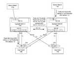
- FIG. 1illustrates an embodiment of a resilient network 100 with multi-chassis link aggregation that provides an active/active paradigm (i.e., all links actively forwarding traffic at the same time) that more fully utilizes the capacity of the network nodes.
- active/active paradigmi.e., all links actively forwarding traffic at the same time
- CMM Chassis Management ModuleIGMP Internet Group Management Protocol IP Internet Protocol IPMS Internet Protocol Multicast LAG Link Aggregation L2 Layer 2 (“Data Link Layer”) of the OSI model for networks L3 Layer 3 (“Network Layer”) of the OSI model for networks MAC Media Access Control Protocol MC-LAG Multi-Chassis Link Aggregate Group MC-VFA Multi-Chassis Virtual Fabric Aggregation NIM Network Interface Module STP Spanning Tree Protocol VLAN Virtual Local Area Network VRRP Virtual Router Redundancy Protocol ASIC Application Specific Integrated Circuit
- LACPLink Aggregation Control Protocol
- the LACPprovides a method to control the bundling of several physical links, called a link aggregation group (LAG), between two peer nodes to form a single logical channel there between.
- the peer nodesnegotiate the bundling of the physical links into a LAG by exchanging LACP packets, or alternatively the LAG can be configured manually.
- Link aggregationoffers an inexpensive way to transfer more data than any one single port or link can deliver alone.
- the ports of a LAGinclude the same physical type, such as all copper ports (CAT-5E/CAT-6), all multi-mode fiber ports (SX), or all single-mode fiber ports (LX).
- the ports of a LAGmay have a different physical type.
- a LAGis split across two devices as seen in FIG. 1 and is referred to herein as a multi-chassis link aggregation group (MC-LAG) 102 .
- MC-LAG 102 aoriginates from edge node 104 and is split into two subsets and connected to two Aggregation Switches 106 a and 106 b , with one or more physical links of the MC-LAG 102 a in each subset.
- the edge node 104may use load balancing techniques to distribute traffic across all available links of the MC-LAG 102 a .
- one of the physical linksis selected based on a load-balancing algorithm (usually involving a hash function operating on the source and destination Internet Protocol (IP) or Media Access Control (MAC) address information). Load balancing across the physical links of the MC-LAG 102 results in a more effective use of bandwidth.
- IPInternet Protocol
- MACMedia Access Control
- the edge node 104is connected over an access network 122 to an enterprise network device 110 , such as a bridge, switch, router, etc., that is operating in a LAN, and/or it may also be connected to a home network device 112 , such as a DSL modem, set-top box, optical line terminal, etc.
- the edge node 104is a switch or server and may functionally include a digital subscriber line access multiplexer (DSLAM), cable modem termination system (CMTS), optical line terminal (OLT), etc. in an embodiment but may include other types of devices as well.
- DSLAMdigital subscriber line access multiplexer
- CMTScable modem termination system
- OLToptical line terminal
- the Aggregation Switches 106are coupled with a virtual fabric link (VFL) 124 .
- VFL 124provides a connection for exchange of information between the Aggregation Switches regarding traffic forwarding, MAC addressing, multicast flows, address resolution protocol (ARP) tables, Layer 2 control protocols (e.g. spanning tree, Ethernet ring protection, logical link detection protocol), routing protocols (e.g. RIP, OSPF, BGP) and the status of the MC-LAG 102 a .
- the Aggregation Switches 106operate transparently to the edge node 104 and are treated as a single logical device by the edge node 104 .
- the edge node 104is able to actively forward traffic on the MC-LAG 102 a while the synchronization of MAC address tables and other forwarding information between the Aggregation Switches 106 is driven by L2 packet flows over the VFL along with a reduced amount of control messaging in an embodiment.
- This featureenables dual homing of the edge node 104 to the pair of Aggregation Switches 106 and provides a Layer 2 multi-path intra-structure as well as basic Layer 3 access infra-structure.
- the MC-VFA featureprovides this functionality without requiring Layer 2 redundancy protocols (e.g.
- Spanning Treebetween the edge node 104 and Aggregation Switches 106 , while still facilitating a carrier-grade detection and convergence time to edge uplink failures as well as aggregation/core switch failures.
- Many recent network designs, especially for data centers,are requiring an ever increasing number of layer 2 adjacencies between edge node and Aggregation Switches. This trend is pushing the limits of the spanning tree protocol, such as loop-detection function and convergence times.
- the spanning tree convergence timecan be of up to several seconds in many current network topologies.
- the multi-chassis architecturein an embodiment provides a dual-homed, layer 2 multi-path connection between the edge node 104 and Aggregation Switches 106 preferably without needing to run the spanning tree protocol operation for loop prevention, while still being flexible enough to allow the spanning tree protocol operation along with the multi-chassis functionality in some of the portions of the network topology in an embodiment (e.g. between the Aggregation Switches over the virtual fabric link as well as over the links connecting these devices to upstream/core switches).
- the feature in some embodimentsalso facilitates fast fail-over detection and convergence times for access uplink failures, virtual fabric link failures and node failures.
- Another advantage of the MC-VFA architecture in an embodimentis the active/active forwarding mode of the edge node 104 whereby both sets of operational MC-LAG uplinks are processing traffic to increase efficiency of the use of bandwidth of the MC-LAG links.
- the Aggregation Switches 106are also connected to a metro or core network 120 that includes one or more network nodes 116 , such as network switches and/or routers, using the MC-LAG functionality (as part of the M-VFA architecture) as described herein.
- aggregate switch 106 bis connected to network nodes 116 b and 116 c over MC-LAG 102 b wherein the network nodes 116 b and 116 c exchange state information over a VFL as well.
- the MC-LAG 102 b architectureprovides a dual-homed, layer 2 multi-path connection between the aggregation switch 106 b and network nodes 116 b and 116 c .
- network nodes 116can also be connected using MC-LAG functionality, as seen with MC-LAG 102 c and VFL 124 .
- the Aggregation Switches 106may also be connected to the network nodes 116 using a standard LAG, such as LAG 118 , or other trunks or links.
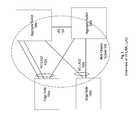
- Edge node 104 ais connected to Aggregation Switches 106 a and 106 b by a first MC-LAG 1 102 a while edge node 104 b is connected to Aggregation Switches 104 a and 104 b by second MC-LAG 2 102 b .
- Each MC-LAG 102 a and 102 bincludes a plurality of physical links divided into at least two subsets, wherein each of the two subsets includes at least one physical link. As seen in FIG.
- the first set of MC-LAG 102 a physical linksare terminated at a first Aggregation Switch 106 a while the second set of MC-LAG 102 a physical links are terminated at a second Aggregation Switch 106 b .
- MC-LAG 1forms logical dual homed, layer 2 multi-paths.
- the MC-LAG member portsare the external, user ports that are members of the MC-LAG 102 .
- the VFL 124is an aggregate of ports that in an embodiment span multiple network interface modules for resiliency and provides for inter-chassis traffic and control/state data transfer.
- the multi-chassis system 140includes the Aggregation Switches 106 , the virtual fabric link 124 , the MC-LAG 102 a , the MC-LAG 102 b and their respective MC-LAG member ports attached to the downstream edge devices.
- the Aggregation Switches 106 a and 106 bare separate physical switches with each operable as a stand-alone switch and each encased by its own separate physical chassis.
- the aggregates switches 106 a and 106 bmay be in the same geographic area, such as in a central office or data center, or may be separate geographic locations, such as different buildings or cities, to provide geo diversity.
- the edge nodes 104 operating as MC-LAG clients attached to the Aggregation Switchescan use different methods to assign traffic to the links within their aggregates as long as the choice of links remains fixed for a given flow. This ensures that traffic is delivered in-sequence between any pair of communicating end stations.
- the same number of uplink ports from the edge devices to each one of the MC-LAG Aggregation Switchesshould preferably be configured. In other words, if two uplinks are configured between the edge switch and one of the MC-LAG Aggregation Switches, then two uplinks between the edge switch and the other multi-chassis switch should also be configured. Although not mandatory, this arrangement provides a more homogeneous traffic distribution for flows between the multi-chassis switches and the edge device.
- the Virtual fabric link (VFL) 124 between the Aggregation Switches 106is now described in more detail with respect to FIG. 3 .
- the Aggregation Switches 106in one embodiment each include at least one CMM module 150 a (primary) and preferably a second CMM module 150 b (back-up) as well as a plurality of Network Interface modules (NIM) 152 , such as line cards or port modules.
- the VFL 124is an aggregate of VFL member ports connected to one or more NIMs 152 , in the first and second Aggregation Switches 106 .
- VFL 124includes a first subset A of physical links between NIM 152 a of Aggregation Switch 106 a and NIM 152 b of Aggregation Switch 106 b , and a second subset B of physical links between NIMs 152 n of Aggregation Switch 106 a and 106 b .
- the VFL linksare connected between Switching ASICs 210 residing in the NIMs 152 of the Aggregation Switches 106 .
- the NIMs 152each also include a Queuing ASIC 212 , described further below.
- a switching fabric integrated circuit (IC) 214provides an interconnection between the various NIMs 152 in the Aggregation Switch 106 .
- a unique chassis identifieris assigned to each Aggregation Switch 106 in the multi-chassis system.
- the Chassis ID for each Aggregation Switch 106is unique and global, e.g. each Aggregation Switch is aware of the chassis ID of its peer Aggregation Switch.
- Unique hardware device identifiers (MIDs) for various components, such as IC, NIM, CMM, in each Aggregation Switchare also generated allowing for management of local and remote objects.
- the hardware device identifiers for the Switching ASICs 210have global significance within the multi-chassis system while MIDs for other components, such as Queuing ASICs 212 , may have only local significance.
- the hardware device identifiers' assigned to the Switching ASICs 210are known by both Aggregation Switches 106 while hardware device identifiers for other devices are restricted to a local Aggregation Switch and have no significance to the remote Aggregation Switch.
- the Switching ASICs 210are assigned a global unique hardware device identifier (MID) in a range assigned to its Aggregation Switch, such as:
- Exemplary MIDs assigned to Switching ASICs 210are shown in FIG. 3 .
- a moduleis able to determine the location of a switching ASIC from its MID as in Aggregation Switch 106 a or Aggregation Switch 106 b.
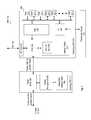
- FIG. 4illustrates a schematic block diagram of an embodiment of a network interface module (NIM) 152 in more detail.
- the Switching ASIC 210includes a plurality of external port interfaces 240 that are connected to external nodes, such as edge nodes 104 a and 104 b .
- One or more of the external port interfaces 240may include member ports for a MC-LAG physical link, LAG or other trunk group, fixed link, etc.
- the external ports 240may have the same physical interface type, such as copper ports (CAT-5E/CAT-6), multi-mode fiber ports (SX) or single-mode fiber ports (LX).
- the external ports 240may have one or more different physical interface types.
- the external ports 240are assigned an external port interface identifiers (Port ID), e.g., device port values, such as gport and dport values, associated with the Switching ASICs 210 .
- Port IDe.g., device port values, such as gport and dport values
- MIDs of the Switching ASICs 210 and an external port interface identifiers for external ports 240 on the Switching ASICs 210are used to uniquely identify a physical external port interface 240 of a Switching ASIC 210 on either the local or remote Aggregation Switch in the multi-chassis system.
- a Port Mangerthat includes a conversion module or other entity may convert the MIDs of the Switching ASICs 210 and external port identifiers into a single integer value, to generate a global port value (GPV), e.g. MID 4 ; device port identifier (dport) 5 converts to GPV 20 .
- GDVglobal port value
- MID 4device port identifier
- device port identifier (dport) 5converts to GPV 20 .
- unique external port identifiers for the external ports of NIMs 152 in both the local and remote Aggregation Switchesare generated.
- Unique port identifiersmay also be assigned to internal ports of a Switching ASIC 210 , such as an internal port from the Switching ASIC 210 to a processing module on the NIM 152 . These internal ports are also uniquely identified by the port identifier and the MID of the Switching ASIC.
- the Switching ASIC 210further includes a packet management unit (PMU) 242 that determines a destination address of incoming packets.
- PMUpacket management unit
- the packetsmay be switched to another external port interface 240 of the Switching ASIC 210 , to the Queuing ASIC 212 for transmission to another NIM 152 on the local or remote aggregate switch, or to the processor interface (PI) 244 for transmission to a processing module 266 of the NIM 152 external or internal to the Switching ASIC 210 .
- PMUpacket management unit
- the Switching ASIC 210transfers the packet to a pre-pended packet header interface (PPHI) that adds or otherwise modifies the packet header to include hardware device information (HDI).
- the HDIincludes identifiers of hardware devices associated with the source and/or the destination of the packet.
- the pre-pended headermay include other information such as packet priority and load balance identifiers.
- the PPHIperforms a look-up process to MAC/HDI forwarding table 250 .
- the MAC/HDI forwarding table 250 stored in the address table memory 248includes a list of MAC address entries, such as MAC address for external devices, nodes, modules, software or hardware connected to the Aggregation Switch 106 .
- the MAC address entriesinclude associated hardware device information used in bridging or routing a packet to reach a device with the associated MAC address.
- the destination hardware device informationmay include the global port value (GPV) of the external port interface associated with the destination MAC address.
- GPSglobal port value
- the MAC/HDI forwarding table 250may include one or more tables, such as source trunk map, trunk bitmap table, trunk group tables, VLAN mapping table, etc.
- the MAC/HDI forwarding table 250 or parts thereofmay be located in the Queuing ASIC of the NIM 152 as well.
- the MAC/HDI forwarding table 250may include additional HDI information, such as a table to associate gport values into Switching ASIC MID values and device port values and/or a table with logical aggregate group identifiers mapping to external port interfaces.
- the pre-pended headerincludes hardware device information HDI associated with the source port, such as an external or internal port interface, including hardware device identifier MID of the Switching ASIC and device port identifier of the source port).
- hardware device information HDIassociated with the source port, such as an external or internal port interface, including hardware device identifier MID of the Switching ASIC and device port identifier of the source port).
- the Switching ASIC 210 connected to the VFL portwill then translate or convert the HDI in the pre-pended header before transmitting the packet over the VFL.
- the PPHI 246also appends source hardware device information associated with the source port, e.g. the external port interface 240 that first received the packet.
- the source hardware device informationmay include the MID of the Switching ASIC 210 and the port identifier (e.g., device port) and/or global port value (GPV) of the external port interface 240 .
- Additional informationsuch as destination hardware device identifier or MID, a destination device port, VLAN ID, packet type (multicast, unicast, broadcast), packet priority and load balance identifier is also added to the pre-pended header in an embodiment.
- the destination HDIis retrieved from the address tables 248 , such as MAC/HDI forwarding table 250 .
- the packet with the pre-pended headeris then transmitted to the Queuing ASIC 212 for routing over the Fabric IC 214 .
- the Queuing ASIC 212includes a packet buffer 260 , a queue management 262 for providing traffic and buffer management and a global HDI address table 264 .
- the global HDI address table 264maps the destination HDI to the appropriate queues in Queuing ASICs 212 in one or more of the other NIMs 152 . For example, the mapping provides information for switching the packet into an appropriate egress queue for one or more of the external port interfaces in other Queuing/Switching ASICs in the Aggregation Switch 106 based on the hardware device information in the pre-pended header.
- the Queuing ASIC 212switches the packet to an appropriate egress queue for one or more of the VFL port interfaces in the local Aggregation Switch 106 for transmission to the remote Aggregation Switch over the VFL 124 , e.g. the global HDI address table 264 indicates that the associated hardware device is located on the remote Aggregation Switch.
- the determination of the egress queue corresponding to a particular VFL port interfaceis made based on the load balance identifier present in the pre-pended header and inserted previously by the switching ASIC 210 .
- switching ASIC 210 and Queuing ASIC 212are illustrated as separate integrated circuits or modules, one or more functions or components of the ASICs may be included on the other ASIC or combined into an alternate ASIC or otherwise be implemented in one or more integrated circuits.
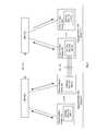
- FIG. 5illustrates a schematic block diagram of an embodiment of a packet flow through Aggregation Switch 106 a to VFL 124 .
- a device 300 with source MAC addresssuch as enterprise device 110 or home network device 112 , transmits a packet, e.g. through edge node 104 , to Aggregation Switch 106 a with a destination MAC address of a device that may be accessed over an external port interface of the remote Aggregation Switch 106 b .
- the Switching ASIC 210 nextracts a destination MAC address and performs an address table look-up to determine hardware device information (HDI) associated with the destination MAC address from MAC/HDI forwarding table 250 .
- the destination HDImay include, e.g., device module identifiers (MIDs) of one or more hardware components in a path to the destination device with the MAC address, such as NIMs 152 , Queuing ASICs 212 , Switching ASICS 210 , external port identifiers 240 , member ports of the VFL 124 , of either the local Aggregation Switch 106 a or remote Aggregation Switch 106 b .
- MIDsdevice module identifiers
- the destination HDImay include the MID of the Switching ASIC 210 and port identifier (e.g., device port) of the external port interface 240 that provides access to the destination device.
- the pre-pended headerincludes a packet priority and a load balance identifier determined based on parameters retrieved from the original packet (source MAC address, destination MAC address, source IP address, destination IP address).
- the HDIwould include a global port value (GPV) for the external port interface 240 or MID of the NIM 152 that provides access to the destination device.
- GPVglobal port value
- the destination HDIis added to a pre-pended header that adds information to the original packet header (such as a layer 2, Ethernet packet header type).
- the source HDImay include one or more hardware device identifiers, such as MID of the originating Switching ASIC 210 , source port identifier (e.g. device port), global port value, MID for source NIM 152 , Chassis ID, etc.
- the packet with pre-pended headeris transmitted to the Queuing ASIC 212 n which then determines a NIM 152 on the local Aggregation Switch to transmit the packet based on the destination HDI.
- the Queuing ASIC 212 nplaces the packet in an egress queue for transmission to the corresponding NIM 152 of the local external port interface.
- the Queuing ASIC 212 ndetermines that the destination HDI indicates a destination hardware device on the remote Aggregation Switch, e.g.
- the packetneeds to be transmitted over the VFL 124 .
- the Queuing ASIC 212 ntransmits the packet with pre-pended header from a queue over the Fabric IC 214 to NIM 152 a connected to the VFL 124 .
- the selection of a VFL member portis made based on the load balance identifier parameters carried on the pre-pended header.
- the Queuing ASIC 212 a on NIM 152 areceives the packet with pre-pended header and queues the packet for transmission over the VFL 124 .
- the Switching ASIC 210 athen transmits the packet with pre-pended header including the source and/or destination HDI to the remote Aggregation Switch over the VFL 124 .
- the Switching ASIC 210 amay alter the pre-pended header prior to transmission over the VFL 124 .
- the Switching ASCI 210 amay translate a destination HDI with local significance (e.g., a gport value or local hardware device identifier MID) to an HDI with global significance.
- the Switching ASIC 210 athen transmits the packet with pre-pended header including the source and/or destination HDI to the remote Aggregation Switch over the VFL 124 .
- the traffic to be transmitted over the VFL 124may be distributed.
- a load balance identifier map table in the Global HDI Address Table 264 of the Queueing ASIC 212would indicate the following distribution:
- VFL 124Destination MID Outgoing Port MID's Device Location [0-31] VFL 124 Local [32-63] VFL 124 Remote
- the Queueing ASICs 212map the packets to the appropriate VFL port interface using the load balance identifiers or other load balancing techniques. For example, in an embodiment with 8 NIMs 152 on each Aggregation Switch, each Queuing ASIC 212 n has a set of 8 queues configured to each NIM (Module ID, Port) within the local Aggregation Switch. In an embodiment, the Queuing ASICs 212 connected to the Switching ASICs 210 with the VFL 124 have a separate set of 8 queues related to each VFL member port interface. Each of those queues is assigned to the FIFOs associated with the internal VFL ports connecting the multi-chassis switches. In an embodiment, with multiple Virtual Fabric Link member ports, the queues are assigned such that the destination ports on the remote chassis are equally distributed among the Queuing ASICs 212 a and 212 n that host the Virtual Fabric Link Member Ports.
- the MAC/HDI forwarding tables in the NIMs 152are populated and then updated in response to layer 2 packets flow through the system. Since the pre-pended header includes source MAC address and source HDI information, the NIMS 152 , e.g. in specific the Switching ASICs 210 in an embodiment, are able to populate the MAC/HDI forwarding table 250 with this information. By operating in a pre-pended header mode to exchange Layer 2 packets with source MAC addresses and source HDI over the VFL 124 , the Switching ASICs 210 are able to synchronize MAC address tables between the Aggregation Switches 106 .
- the MAC/HDI forwarding tableis described in the Switching ASICs 210 , the MAC/HDI forwarding table may be included, alternatively or in addition to, in the Queuing ASICs 212 n or other module of the NIM 152 .
- the CMM 150(primary and secondary) may also include a MAC/HDI forwarding table for one or more types of links between the Aggregation Switches 106 .
- FIG. 6illustrates a schematic block diagram of an embodiment of a multi-chassis system that illustrates source MAC learning.
- Edge nodes 104are connected to Aggregation Switches 106 a and 106 b over logical aggregate group LAG 1 282 , multi-chassis logical aggregate group MC-LAG 1 102 a , multi-chassis logical aggregate group MC-LAG 2 102 b and fixed port link 280 .
- each Aggregation Switchcommunicates to the other Aggregation Switch configuration information for logical aggregate groups, such as LAG 1 and other types of trunk groups, and hardware device information associated thereto.
- the hardware device informationincludes physical ports associated with the logical aggregate groups, e.g. hardware device or module identifiers (MID) of Switching ASICS and external port identifiers for links associated with the logical aggregate groups (device port values or gport values).
- MIDhardware device or module identifiers
- Other hardware device informationsuch as identifiers of NIMs, Queuing ASICs, etc. associated with the logical aggregate groups may be exchanged alternatively or in addition to the Switching ASIC's MIDs and device port values.
- the Aggregation Switches 106also provide notifications of updates to the configuration information of the logical aggregate groups for both ordinary aggregates and multi-chassis aggregate groups.
- the hardware device information associated with the logical aggregate groups and multi-chassis aggregates of either of the Aggregation Switchesis included in one or more of the MAC/HDI forwarding tables in NIMs 152 on both Aggregation Switches.
- one or more of the MAC/HDI forwarding tables in both Aggregation Switches 106includes the following information:
- the multi-chassis systemassigns a subset of aggregate group identifiers to each type of logical group and for each of the Aggregation Switches 106 . For example, in an embodiment with a maximum of 128 possible aggregate groups, an assignment of aggregate group identifiers would include:
- the Aggregation Switches 106assign aggregate group identifiers based on the assigned ranges and type of aggregate group. As such, packet forwarding in the Aggregation Switches is performed by accessing the MAC/HDI forwarding tables and using the mapping between the logical aggregate groups and hardware device information. Typically, aggregate identifier information is not transferred in the pre-pended headers.
- an Aggregation Switch 106determines whether the destination HDI is included in a logical aggregate group by searching for the port identified in the source HDI (destination MID, destination Port identifier) in one or more of its internal trunk tables that contain a list of all ports that are active members of each LAG or MC-LAG aggregate group.
- the Aggregation Switch 106may perform load balancing techniques by assigning the packet to one or more different external port interfaces of the associated LAG.
- the Source MAC addressis populated in MAC/HDI forwarding tables on both Aggregation Switches 106 a and 106 b as associated with hardware device information (HDI) of the originating configured fixed port (such as MID of Switching ASIC and source port identifier value or gport value of the source port, NIM identifier, or other hardware device ID associated with the source port).
- HDIhardware device information
- the Source MAC addressis populated in MAC/HDI forwarding tables on both Aggregation Switches 106 a and 106 b as associated with the originating logical aggregate group identifier (e.g., LAG 1 ).
- the source MAC address a 1 received on LAG 1 by Aggregation Switch Ais stored in one or more MAC/HDI forwarding tables of both the Aggregation Switches 106 with the VLAN ID and logical aggregate group identifier LAG 1 .
- the MAC/HDI forwarding tables of both Aggregation Switchesstore the hardware device information associated with logical aggregate groups (learned through distribution of configuration information by the CMM 150 module or other control plane process).
- the MAC/HDI forwarding tablesthus include information that MAC address a 1 is associated with trunk group identifier LAG 1 and HDI information associated with LAG 1 .
- the Source MACis populated in MAC/HDI forwarding tables as associated with the MC-LAG identifier and HDI information of the local member ports of the MC-LAG.
- the HDI information of the member ports of the MC-LAGwill be the same for the MAC/LAG tables on each Aggregation Switch 106 .
- both Aggregation Switchesare fully aware of the entire list of member ports that are active participants of an MC-LAG aggregate group regardless of whether a member port is local or remote.
- one or more of the MAC/HDI forwarding tables on the Aggregation Switches 106includes the following information:
- MAC address tables displayed in a node or network management applicationmay not include the HDI for the logical aggregation groups.
- the user displayed MAC address tablemay only include HDI for fixed ports and thus are similar for both Aggregation Switches 106 .
- the MAC/HDI forwarding tablesare synchronized with respect to the LAG identifiers associated with the source MAC addresses.
- VLAN IDs associated with the MAC addressesmay also be configured and synchronized on both Aggregation Switches.
- the Aggregation Switches 106operate as a single bridge for MAC learning.
- MAC learningoccurs automatically as traffic flows over the VFL 124 with minimum Layer 2/control module management software intervention and without the need for inter-process communication message-based MAC table synchronization.
- FIG. 7illustrates an embodiment of a method for source MAC learning in a multi-chassis system in more detail.
- ARPaddress resolution packet
- the MAC address requestmay include:
- VLAN IDID
- the edge node 104 aWhen received by the edge node 104 a , it forwards the MAC address request over MC-LAG A to the “logical” Aggregation Switch 106 (composed of two physical switches 106 a and 106 b ). Depending on the load balancing or hashing algorithm, the edge node 104 a may transmit the MAC address request over either of the subsets of physical links of MC-LAG A, either L A1 or L A2 . For this example, assume that the MAC address request is transmitted over L A1 connected to Aggregation Switch 106 a . In general, in an Ethernet switch, a MAC address request (such as ARP) is copied and broadcast over every port associated with the VLAN ID.
- ARPMAC address request
- the Aggregation Switch 106 aalso transmits the broadcast packet with pre-pended header over the VFL 124 to Aggregation Switch 106 b .
- the Aggregation Switch 106 balso learns the source MAC address and associated aggregate group identifier and/or source HDI from the broadcast packet with pre-pended header.
- MAC addresses originating on MC-LAG local member ports in one Aggregation Switch and transmitted over the VFLare associated in the peer Aggregation Switch with the same MC-LAG because both switches are fully aware of the entire list of MC-LAG member ports.
- a loop prevention mechanismprevents broadcast of packets received by an Aggregation Switch 106 over the Virtual Fabric Link 124 over local MC-LAG member ports.
- Aggregation Switch 106 breceives the MAC address request over VFL 124 , it will not broadcast copies of the MAC address request over local MC-LAG A member ports L A2 and local MC-LAG B member ports L B2 .
- This loop prevention mechanismprevents broadcast packet flows originating from Aggregation Switch A from looping to edge Node A and edge Node B through Aggregation Switch B. The loop prevention process thus provides for operation of the multi-chassis domain system without need of the spanning tree protocol on the MC-LAG member ports.
- the Aggregation Switches 106 a and 106 bdo not generate a response to the MAC address request because the destination IP address does not correspond to any of its local IP interfaces configured on its local VLANs.
- edge node Breceives the MAC address request (over L B1 )
- itwill broadcast the packet to Device B which will then respond.
- the response packetwhich is a unicast packet, traverses the multi-chassis system to Device A
- the source MAC address of Device Bis learnt by the Aggregation Switches 106 in a similar process.
- Device A and Device Bnow are able to communicate with IP addressing over the Layer 2 multi-path infrastructure provided by the multi-chassis link aggregates.
- MAC addressesare learned as either associated with a particular port (for the case of fixed ports) or as associated with an aggregate group identifier (for the case of LAGs or MC-LAGs). Since the Aggregate Switches 106 have non-overlapping ranges of hardware device identifiers, MIDs, the hardware device identifiers are unique within the multi-chassis system 140 . Using the global unique hardware device identifiers MIDs and external port identifiers, the MAC addresses can be associated with a fixed ports or aggregate group identifier.
- FIG. 8illustrates a schematic block diagram of an embodiment for maintaining the MAC/HDI forwarding tables in the multi-chassis system.
- the MAC forwarding tableshave a default or configured “aging” time for entries. When a MAC address in the MAC/HDI forwarding table has not been updated during the aging time, the entry will be deleted or flushed from the table. In the multi-chassis system however, the aging of entries may create a problem with continuous flooding when packet flows have different paths for the upstream and downstream directions. In order to maintain the MAC forwarding tables synchronized, a multi-chassis system needs to implement a keep-alive mechanism across the entire set of switches that are part of the system.
- Keep-alive packetsare periodic packets (sent at a constant interval equal to the aging timeout parameter). These packets carry a reserved multicast destination MAC address to allow the packets to be flooded to all Switching ASIC devices 210 within all NIMs 152 in the multi-chassis system.
- the source MAC address of the packetsis equal to the MAC address of each entry learned within the MAC forwarding table. As a result of this mechanism, a given MAC address will not age and be deleted or flushed unless it is no longer used in any of the Aggregate Switches within the multi-chassis system.
- a MAC entryis assigned an “owner” or responsible module within the multi-chassis system.
- the owner of a MAC entryis generally a particular NIM 152 .
- the MAC ownershipis determined in different ways. For example, the MAC ownership may depend on the type of port on which it was first learned as follows. For MAC addresses associated with fixed ports, the Switching ASIC device 210 that contains the external port where the MAC address traffic was received is the owner of the MAC entry and controls the aging of the MAC address. Other Switching ASICs 210 learn this MAC address upon reception of a packet with a pre-pended header. The NIMs 152 that host such Switching ASIC devices 210 will not become owners of the MAC entry. A device becomes the owner of a MAC entry related to a fixed port only when it learned that address on from an external port interface.
- the owner of a MAC addressis determined by a similar mechanism as described for the fixed ports.
- the Switching ASICs 210typically provide an additional feature called remote or local bit. This bit is only set when an entry is created and it never changes its value during the lifetime of a MAC entry.
- the NIMs 152coordinate deleting an entry from the MAC/HDI forwarding tables.
- a logical inter-process communication connection (IPC) 310is created between the CMMs 150 a and 150 b of the Aggregation Switches 106 .
- the same logical connectionsexist between any pair of NIMs 152 .
- the IPC 310may be created over the VFL 124 or over a LAN connection.
- the MAC/HDI tables in the Switching and/or Queuing ASICs in the NIMs 152 a - nthen flush the entry for the corresponding MAC address.
- the decision to whether delete the entry locally or notdepends on the entry's ownership and type of port where the MAC entry was learned. Entries learned on fixed ports or ordinary aggregates (i.e. LAG) are flushed (and the corresponding event propagated) only if the flush request was received on the NIM 152 that owns the entry. Entries learned on MC-LAG aggregates are only flushed (and the flush event propagated) if there are no active/operational ports that are members of the aggregate neither in the local switch nor on the remote switch.
- LAGordinary aggregates
- CMM 150 a - b and NIMs 152 a - nare aware of the entire list of MC-LAG member ports and their states (active/inactive) in the multi-chassis system.
- the flush messageincludes a local port identifier (e.g., gport values) that is valid only on the local Aggregation Switch
- the NIM 152 that owns that MAC address being deletedconverts the local port identifier to a global port identifier (e.g. MID or modid and device port values) and then transmits the flush message over the IPC to the other NIMs 152 a - n of the local and remote Aggregation Switches 106 a/b .
- the flushing requestsmay be triggered by distinct events such a port interface status notifications (e.g. port down) or via explicit management request. For example, when CMM 150 a receives a ‘no mac-learning dynamic’ management message or a static MAC address is deleted upon user request, and the flush allowance requirements describer earlier are met, then the CMM 150 a transmits a flush message with the MAC address to NIMs 150 a - n of Aggregation Switch 106 a and to CMM 150 b of the remote Aggregation Switch 106 b.
- one or more of the links of an MC-LAG in the multi-chassis systemmay operate in standby mode.
- FIG. 9illustrates an embodiment in which a first subset of links L A2 of MC-LAG 1 102 a and a second subset of links L B1 of MC-LAG 2 102 b are operating in standby mode. Unless a failure occurs, traffic is not transmitted over local MC-LAG member ports in standby node. Instead, the traffic is transmitted over the VFL to peer Aggregation Switch for transmission over corresponding MC-LAG member ports in active mode.
- Aggregation Switch Bdoes not transmit broadcast packets received over the VFL 124 over MC-LAG local member ports for loop prevention purposes.
- Aggregation Switch Btransmits broadcast packets to MC-LAG local member ports in active mode.
- Aggregation Switch Bremoves the pre-pended header and keeps the inner standard Ethernet/IP packet header and broadcasts the packet to edge node C over L B2 of MC-LAG 2 .
- the active/standby modecan be configured or implemented for maintenance reasons. Standby mode for local member ports of an MC-LAG can also be implemented due to a failure.
- the multi-chassis systemprovides fast fail over convergence in response to a failure by either re-directing traffic through the VFL and/or creating a new path by implementing a MAC flush message to delete a set of MAC table entries from the MAC/HDI forwarding table. A new path is then automatically learned through the multi-chassis system using source MAC learning via packet flow as described herein.
- FIG. 11illustrate a schematic block diagram of an embodiment of a multi-chassis system when a failure occurs in MC-LAG links.
- the MAC address entries associated with ports of MC-LAG 1 in MAC/HDI forwarding tablesare flushed on Aggregation Switches 106 a and 106 b but not on the network nodes 116 a and 116 b .
- the MAC addresses associated with MC-LAG 1 's portse.g.
- the Aggregation Switch Bwill treat the MAC address as unknown and broadcast a MAC address request.
- LAGlogical aggregate group
- the MAC/HDI forwarding tablesare thus repopulated after a failure with the new path information by layer 2 packet flows through the Aggregation Switches 106 rather than using a spanning tree protocol or layer 2 MAC table control messages generated synchronization messages.
- FIG. 12illustrates a schematic block diagram of an embodiment of a pre-pended header of a packet in the multi-chassis system.
- the pre-pended header 300includes fields for source HDI 302 , destination HDI 304 , VLAN ID 306 , packet type 308 , source MAC address 310 , destination MAC address 312 .
- the pre-pended headermay also include, load balance identifier 314 and packet priority 316 .
- the destination hardware device informationmay include the global port value (GPV) of the external port interface associated the destination MAC address.
- the destination hardware device informationmay also include MID of the Switching ASIC 210 connected to the VFL, NIMs 152 , Queuing ASICs, etc.
- the source HDI 302may include the MID of the Switching ASIC 210 and the port identifier (e.g., device port) and/or global port value (GPV) of the external port interface 240 .
- the load balance identifier 314is used to help the Queueing ASIC 212 to decide which VFL member port to be used as a transit/gateway port to reach the peer Aggregate Switch.
- the packet priority 316is used by the Queueing ASIC 212 to determine the specific priority queue.
- the network interface modules 152includes one or more processing devices, such as a microprocessor, micro-controller, digital signal processor, microcomputer, central processing unit, field programmable gate array, programmable logic device, state machine, logic circuitry, analog circuitry, digital circuitry, and/or any device that manipulates signals (analog and/or digital) based on hard coding of the circuitry and/or operational instructions.
- the NIMs 152includes a memory that is an internal memory or an external memory.
- the memory of the NIMs 152may be a single memory device or a plurality of memory devices.
- Such a memory devicemay be a read-only memory, random access memory, volatile memory, non-volatile memory, static memory, dynamic memory, flash memory, cache memory, and/or any device that stores digital information.
- the NIMs 152may implement one or more of its functions via a state machine, analog circuitry, digital circuitry, and/or logic circuitry, the memory storing the corresponding operational instructions may be embedded within, or external to, the circuitry comprising the state machine, analog circuitry, digital circuitry, and/or logic circuitry.
- the NIMs 152may execute hard-coded and/or software and/or operational instructions stored by the internal memory and/or external memory to perform the steps and/or functions described herein.
- the NIMs 152may be implemented in a single or in one or more integrated circuits.
- the terms “substantially” and “approximately”provides an industry-accepted tolerance for its corresponding term and/or relativity between items. Such an industry-accepted tolerance ranges from less than one percent to fifty percent and corresponds to, but is not limited to, component values, integrated circuit process variations, temperature variations, rise and fall times, and/or thermal noise. Such relativity between items ranges from a difference of a few percent to magnitude differences.
- the term(s) “coupled to” and/or “coupling” and/orincludes direct coupling between items and/or indirect coupling between items via an intervening item (e.g., an item includes, but is not limited to, a component, an element, a circuit, and/or a module) where, for indirect coupling, the intervening item does not modify the information of a signal but may adjust its current level, voltage level, and/or power level.
- an intervening iteme.g., an item includes, but is not limited to, a component, an element, a circuit, and/or a module
- inferred couplingi.e., where one element is coupled to another element by inference
- the term “operable to”indicates that an item includes one or more of processing modules, data, input(s), output(s), etc., to perform one or more of the described or necessary corresponding functions and may further include inferred coupling to one or more other items to perform the described or necessary corresponding functions.
- the term(s) “connected to” and/or “connecting” or “interconnecting”includes direct connection or link between nodes/devices and/or indirect connection between nodes/devices via an intervening item (e.g., an item includes, but is not limited to, a component, an element, a circuit, a module, a node, device, etc.).
- inferred connectionsi.e., where one element is connected to another element by inference
- inferred connectionsincludes direct and indirect connection between two items in the same manner as “connected to”.
Landscapes
- Engineering & Computer Science (AREA)
- Computer Networks & Wireless Communication (AREA)
- Signal Processing (AREA)
- Computer Security & Cryptography (AREA)
- Data Exchanges In Wide-Area Networks (AREA)
Abstract
Description
| CMM | Chassis Management Module |
| IGMP | Internet Group Management Protocol |
| IP | Internet Protocol |
| IPMS | Internet Protocol Multicast |
| LAG | Link Aggregation |
| L2 | Layer 2 (“Data Link Layer”) of the OSI model for networks |
| L3 | Layer 3 (“Network Layer”) of the OSI model for networks |
| MAC | Media Access Control Protocol |
| MC-LAG | Multi-Chassis Link Aggregate Group |
| MC-VFA | Multi-Chassis Virtual Fabric Aggregation |
| NIM | Network Interface Module |
| STP | Spanning Tree Protocol |
| VLAN | Virtual Local Area Network |
| VRRP | Virtual Router Redundancy Protocol |
| ASIC | Application Specific Integrated Circuit |
| Destination MID | Outgoing Port | MID's Device Location |
| [0-31] | Local | |
| [32-63] | Remote | |
| Type of | Aggregate Group | HDI |
| Aggregate Group | Identifier | List of VFL Member Ports |
| LAG | LAG1 | (MID = 31, Port ID = 1) |
| (MID = 31, Port ID = 2) | ||
| MC-LAG | MC-LAG1 | (MID = 31, Port ID = 3) |
| (MID = 31, Port ID = 4) | ||
| (MID = 45, Port ID = 1) | ||
| (MID = 45, Port ID = 2) | ||
| MC-LAG | MC-LAG2 | (MID = 31, Port ID = 5) |
| (MID = 45, Port ID = 3) | ||
| Type of |
| Aggre- | Aggre- |
| gate | gation | Range |
| Group | Switch | Range Configuration | Default | Example |
| LAG | chassis | MIN_LAG_ID_LOCAL | [0-47] | [0-100] |
| 1 | MAX_LAG_ID_LOCAL | |||
| LAG | chassis | MIN_LAG_ID_REMOTE | [48-95] | [101-120] |
| 2 | MAX_LAG_ID_REMOTE | |||
| MC- | Both | MIN_MC-LAG_ID | [96-127] | [121-127] |
| LAG | chassis | MAX_MC-LAG_ID | ||
The Aggregation Switches106 assign aggregate group identifiers based on the assigned ranges and type of aggregate group. As such, packet forwarding in the Aggregation Switches is performed by accessing the MAC/HDI forwarding tables and using the mapping between the logical aggregate groups and hardware device information. Typically, aggregate identifier information is not transferred in the pre-pended headers.
| Aggregation Switch A |
| LAG ID | HDI | |
| LAG1 | (MID = 31, Port ID = 1) | |
| (MID = 31, Port ID = 2) | ||
| MC-LAG1 | (MID = 31, Port ID = 3) | |
| (MID = 31, Port ID = 4) | ||
| (MID = 45, Port ID = 1) | ||
| (MID = 45, Port ID = 2) | ||
| MC-LAG-2 | (MID = 31, Port ID = 5) | |
| (MID = 45, Port ID = 3) | ||
| Aggregation Switch A |
| MAC | LAG | LAG ID | |||
| a1 | Yes | LAG1 | |||
| b1 | Yes | MC-LAG1 | |||
| c1 | Yes | MC-LAG-2 | |||
| d1 | No | — | |||
| Aggregation Switch B |
| MAC | LAG | LAG ID | |||
| a1 | Yes | LAG1 | |||
| b1 | Yes | MC-LAG1 | |||
| c1 | Yes | MC-LAG-2 | |||
| d1 | No | — | |||
| Aggregation Switch A |
| MAC | LAG | LAG ID | HDI | |||
| a1 | Yes | LAG1 | N/A | |||
| b1 | Yes | MC-LAG1 | N/A | |||
| c1 | Yes | MC-LAG-2 | N/A | |||
| d1 | No | — | (MID = 45, Port ID = 4) | |||
| Aggregation Switch B |
| MAC | LAG | LAG ID | HDI | |||
| a1 | Yes | LAG1 | N/A | |||
| b1 | Yes | MC-LAG1 | N/A | |||
| c1 | Yes | MC-LAG-2 | N/A | |||
| d1 | No | — | (MID = 45, Port ID = 4) | |||
Claims (20)
Priority Applications (11)
| Application Number | Priority Date | Filing Date | Title |
|---|---|---|---|
| US13/010,168US8767735B2 (en) | 2010-08-04 | 2011-01-20 | System and method for multi-chassis link aggregation |
| PCT/US2011/044527WO2012018521A1 (en) | 2010-08-04 | 2011-07-19 | System and method for multi-chassis link aggregation |
| KR1020137002752AKR101455013B1 (en) | 2010-08-04 | 2011-07-19 | System and method for multi-chassis link aggregation |
| JP2013523182AJP5661929B2 (en) | 2010-08-04 | 2011-07-19 | System and method for multi-chassis link aggregation |
| EP11748776.9AEP2601763A1 (en) | 2010-08-04 | 2011-07-19 | System and method for multi-chassis link aggregation |
| CN201180038254.7ACN103098424B (en) | 2010-08-04 | 2011-07-19 | For the system and method for multi-frame aggregation of links |
| US13/431,116US8913489B2 (en) | 2010-08-04 | 2012-03-27 | System and method for virtual fabric link failure recovery |
| US13/674,352US9148391B2 (en) | 2010-08-04 | 2012-11-12 | System and method for a pass thru mode in a virtual chassis system |
| US13/674,392US9172662B2 (en) | 2010-08-04 | 2012-11-12 | Virtual chassis system control protocols |
| US13/674,259US9148389B2 (en) | 2010-08-04 | 2012-11-12 | System and method for a virtual chassis system |
| US13/674,315US9148390B2 (en) | 2010-08-04 | 2012-11-12 | System and method for virtual chassis split prevention |
Applications Claiming Priority (2)
| Application Number | Priority Date | Filing Date | Title |
|---|---|---|---|
| US37062210P | 2010-08-04 | 2010-08-04 | |
| US13/010,168US8767735B2 (en) | 2010-08-04 | 2011-01-20 | System and method for multi-chassis link aggregation |
Related Parent Applications (1)
| Application Number | Title | Priority Date | Filing Date |
|---|---|---|---|
| US13/010,343Continuation-In-PartUS9059940B2 (en) | 2010-08-04 | 2011-01-20 | System and method for transport control protocol in a multi-chassis domain |
Related Child Applications (5)
| Application Number | Title | Priority Date | Filing Date |
|---|---|---|---|
| US13/431,116Continuation-In-PartUS8913489B2 (en) | 2010-08-04 | 2012-03-27 | System and method for virtual fabric link failure recovery |
| US13/674,392Continuation-In-PartUS9172662B2 (en) | 2010-08-04 | 2012-11-12 | Virtual chassis system control protocols |
| US13/674,315Continuation-In-PartUS9148390B2 (en) | 2010-08-04 | 2012-11-12 | System and method for virtual chassis split prevention |
| US13/674,352Continuation-In-PartUS9148391B2 (en) | 2010-08-04 | 2012-11-12 | System and method for a pass thru mode in a virtual chassis system |
| US13/674,259Continuation-In-PartUS9148389B2 (en) | 2010-08-04 | 2012-11-12 | System and method for a virtual chassis system |
Publications (2)
| Publication Number | Publication Date |
|---|---|
| US20120033665A1 US20120033665A1 (en) | 2012-02-09 |
| US8767735B2true US8767735B2 (en) | 2014-07-01 |
Family
ID=44511500
Family Applications (4)
| Application Number | Title | Priority Date | Filing Date |
|---|---|---|---|
| US13/010,168Active2031-09-09US8767735B2 (en) | 2010-08-04 | 2011-01-20 | System and method for multi-chassis link aggregation |
| US13/010,343Active2031-11-20US9059940B2 (en) | 2010-08-04 | 2011-01-20 | System and method for transport control protocol in a multi-chassis domain |
| US13/010,414Active2031-07-25US8488608B2 (en) | 2010-08-04 | 2011-01-20 | System and method for traffic distribution in a multi-chassis link aggregation |
| US13/010,711Active2031-09-14US8462774B2 (en) | 2010-08-04 | 2011-01-20 | Virtual IP interfaces on multi-chassis link aggregates |
Family Applications After (3)
| Application Number | Title | Priority Date | Filing Date |
|---|---|---|---|
| US13/010,343Active2031-11-20US9059940B2 (en) | 2010-08-04 | 2011-01-20 | System and method for transport control protocol in a multi-chassis domain |
| US13/010,414Active2031-07-25US8488608B2 (en) | 2010-08-04 | 2011-01-20 | System and method for traffic distribution in a multi-chassis link aggregation |
| US13/010,711Active2031-09-14US8462774B2 (en) | 2010-08-04 | 2011-01-20 | Virtual IP interfaces on multi-chassis link aggregates |
Country Status (6)
| Country | Link |
|---|---|
| US (4) | US8767735B2 (en) |
| EP (1) | EP2601763A1 (en) |
| JP (1) | JP5661929B2 (en) |
| KR (1) | KR101455013B1 (en) |
| CN (1) | CN103098424B (en) |
| WO (1) | WO2012018521A1 (en) |
Cited By (4)
| Publication number | Priority date | Publication date | Assignee | Title |
|---|---|---|---|---|
| US20140146664A1 (en)* | 2012-11-26 | 2014-05-29 | Level 3 Communications, Llc | Apparatus, system and method for packet switching |
| US9832114B2 (en) | 2012-05-25 | 2017-11-28 | Nec Corporation | Packet forwarding system, control apparatus, packet forwarding method, and program |
| CN109150579A (en)* | 2017-06-19 | 2019-01-04 | 广达电脑股份有限公司 | Method and system for configuring multi-chassis link and storage medium thereof |
| US11425031B2 (en)* | 2019-03-28 | 2022-08-23 | Hewlett Packard Enterprise Development Lp | Layer 3 multi-chassis link aggregation group |
Families Citing this family (248)
| Publication number | Priority date | Publication date | Assignee | Title |
|---|---|---|---|---|
| US7499419B2 (en)* | 2004-09-24 | 2009-03-03 | Fortinet, Inc. | Scalable IP-services enabled multicast forwarding with efficient resource utilization |
| US8798045B1 (en) | 2008-12-29 | 2014-08-05 | Juniper Networks, Inc. | Control plane architecture for switch fabrics |
| US8665886B2 (en) | 2009-03-26 | 2014-03-04 | Brocade Communications Systems, Inc. | Redundant host connection in a routed network |
| US9240923B2 (en)* | 2010-03-23 | 2016-01-19 | Juniper Networks, Inc. | Methods and apparatus for automatically provisioning resources within a distributed control plane of a switch |
| US8369335B2 (en) | 2010-03-24 | 2013-02-05 | Brocade Communications Systems, Inc. | Method and system for extending routing domain to non-routing end stations |
| US8989186B2 (en) | 2010-06-08 | 2015-03-24 | Brocade Communication Systems, Inc. | Virtual port grouping for virtual cluster switching |
| US9769016B2 (en) | 2010-06-07 | 2017-09-19 | Brocade Communications Systems, Inc. | Advanced link tracking for virtual cluster switching |
| US9001824B2 (en) | 2010-05-18 | 2015-04-07 | Brocade Communication Systems, Inc. | Fabric formation for virtual cluster switching |
| US9270486B2 (en) | 2010-06-07 | 2016-02-23 | Brocade Communications Systems, Inc. | Name services for virtual cluster switching |
| US9231890B2 (en) | 2010-06-08 | 2016-01-05 | Brocade Communications Systems, Inc. | Traffic management for virtual cluster switching |
| US8625616B2 (en) | 2010-05-11 | 2014-01-07 | Brocade Communications Systems, Inc. | Converged network extension |
| US9716672B2 (en) | 2010-05-28 | 2017-07-25 | Brocade Communications Systems, Inc. | Distributed configuration management for virtual cluster switching |
| US9461840B2 (en) | 2010-06-02 | 2016-10-04 | Brocade Communications Systems, Inc. | Port profile management for virtual cluster switching |
| US8867552B2 (en) | 2010-05-03 | 2014-10-21 | Brocade Communications Systems, Inc. | Virtual cluster switching |
| US8634308B2 (en) | 2010-06-02 | 2014-01-21 | Brocade Communications Systems, Inc. | Path detection in trill networks |
| US8885488B2 (en) | 2010-06-02 | 2014-11-11 | Brocade Communication Systems, Inc. | Reachability detection in trill networks |
| US9608833B2 (en) | 2010-06-08 | 2017-03-28 | Brocade Communications Systems, Inc. | Supporting multiple multicast trees in trill networks |
| US8446914B2 (en) | 2010-06-08 | 2013-05-21 | Brocade Communications Systems, Inc. | Method and system for link aggregation across multiple switches |
| US9806906B2 (en) | 2010-06-08 | 2017-10-31 | Brocade Communications Systems, Inc. | Flooding packets on a per-virtual-network basis |
| US9628293B2 (en) | 2010-06-08 | 2017-04-18 | Brocade Communications Systems, Inc. | Network layer multicasting in trill networks |
| US9246703B2 (en) | 2010-06-08 | 2016-01-26 | Brocade Communications Systems, Inc. | Remote port mirroring |
| US8837493B2 (en) | 2010-07-06 | 2014-09-16 | Nicira, Inc. | Distributed network control apparatus and method |
| US9680750B2 (en) | 2010-07-06 | 2017-06-13 | Nicira, Inc. | Use of tunnels to hide network addresses |
| US9807031B2 (en) | 2010-07-16 | 2017-10-31 | Brocade Communications Systems, Inc. | System and method for network configuration |
| US8718063B2 (en) | 2010-07-26 | 2014-05-06 | Juniper Networks, Inc. | Methods and apparatus related to route selection within a network |
| US8767735B2 (en)* | 2010-08-04 | 2014-07-01 | Alcatel Lucent | System and method for multi-chassis link aggregation |
| US8913489B2 (en) | 2010-08-04 | 2014-12-16 | Alcatel Lucent | System and method for virtual fabric link failure recovery |
| US8560660B2 (en) | 2010-12-15 | 2013-10-15 | Juniper Networks, Inc. | Methods and apparatus for managing next hop identifiers in a distributed switch fabric system |
| US9282060B2 (en) | 2010-12-15 | 2016-03-08 | Juniper Networks, Inc. | Methods and apparatus for dynamic resource management within a distributed control plane of a switch |
| US9391796B1 (en) | 2010-12-22 | 2016-07-12 | Juniper Networks, Inc. | Methods and apparatus for using border gateway protocol (BGP) for converged fibre channel (FC) control plane |
| US9106527B1 (en) | 2010-12-22 | 2015-08-11 | Juniper Networks, Inc. | Hierarchical resource groups for providing segregated management access to a distributed switch |
| US8730809B2 (en)* | 2011-01-19 | 2014-05-20 | Hewlett-Packard Development Company, L.P. | Methods for packet forwarding through a communication link of a distributed link aggregation group using mesh tagging |
| US8677024B2 (en)* | 2011-03-31 | 2014-03-18 | International Business Machines Corporation | Aggregating shared Ethernet adapters in a virtualized environment |
| CN102118319B (en)* | 2011-04-06 | 2013-09-18 | 杭州华三通信技术有限公司 | Traffic load balancing method and device |
| US8514701B2 (en)* | 2011-04-12 | 2013-08-20 | Qualcomm Innovation Center, Inc. | Aggregating multiple radio links from multiple modems in a communication device |
| AU2011229566B2 (en)* | 2011-04-27 | 2015-12-10 | Huawei Technologies Co., Ltd. | Load sharing method and apparatus |
| US8989009B2 (en)* | 2011-04-29 | 2015-03-24 | Futurewei Technologies, Inc. | Port and priority based flow control mechanism for lossless ethernet |
| US9270572B2 (en) | 2011-05-02 | 2016-02-23 | Brocade Communications Systems Inc. | Layer-3 support in TRILL networks |
| US20120281695A1 (en)* | 2011-05-05 | 2012-11-08 | Brocade Communications Systems, Inc. | Control packet bicasting between stackable devices |
| US8670450B2 (en) | 2011-05-13 | 2014-03-11 | International Business Machines Corporation | Efficient software-based private VLAN solution for distributed virtual switches |
| US8837499B2 (en)* | 2011-05-14 | 2014-09-16 | International Business Machines Corporation | Distributed fabric protocol (DFP) switching network architecture |
| US20120291034A1 (en) | 2011-05-14 | 2012-11-15 | International Business Machines Corporation | Techniques for executing threads in a computing environment |
| US8792501B1 (en)* | 2011-05-25 | 2014-07-29 | Juniper Networks, Inc. | Active-active multi-homing with multi-chassis pseudowire link aggregation |
| US9100213B1 (en)* | 2011-06-08 | 2015-08-04 | Juniper Networks, Inc. | Synchronizing VPLS gateway MAC addresses |
| US9692686B2 (en)* | 2011-06-08 | 2017-06-27 | Dell Products L.P. | Method and system for implementing a multi-chassis link aggregation group in a network |
| US9497073B2 (en) | 2011-06-17 | 2016-11-15 | International Business Machines Corporation | Distributed link aggregation group (LAG) for a layer 2 fabric |
| US9401861B2 (en) | 2011-06-28 | 2016-07-26 | Brocade Communications Systems, Inc. | Scalable MAC address distribution in an Ethernet fabric switch |
| US9407533B2 (en) | 2011-06-28 | 2016-08-02 | Brocade Communications Systems, Inc. | Multicast in a trill network |
| US8879549B2 (en)* | 2011-06-28 | 2014-11-04 | Brocade Communications Systems, Inc. | Clearing forwarding entries dynamically and ensuring consistency of tables across ethernet fabric switch |
| US8948056B2 (en) | 2011-06-28 | 2015-02-03 | Brocade Communication Systems, Inc. | Spanning-tree based loop detection for an ethernet fabric switch |
| US9007958B2 (en) | 2011-06-29 | 2015-04-14 | Brocade Communication Systems, Inc. | External loop detection for an ethernet fabric switch |
| US8885641B2 (en)* | 2011-06-30 | 2014-11-11 | Brocade Communication Systems, Inc. | Efficient trill forwarding |
| US9280357B2 (en)* | 2011-07-12 | 2016-03-08 | Hewlett-Packard Development Company, L.P. | Configuration based on chassis identifications |
| US9729431B1 (en) | 2011-08-16 | 2017-08-08 | Marvell International Ltd. | Using standard fields to carry meta-information |
| US9736085B2 (en) | 2011-08-29 | 2017-08-15 | Brocade Communications Systems, Inc. | End-to end lossless Ethernet in Ethernet fabric |
| US8767529B2 (en) | 2011-09-12 | 2014-07-01 | International Business Machines Corporation | High availability distributed fabric protocol (DFP) switching network architecture |
| US9473424B2 (en)* | 2011-09-19 | 2016-10-18 | Fujitsu Limited | Address table flushing in distributed switching systems |
| US8675522B2 (en)* | 2011-09-23 | 2014-03-18 | Avaya Inc. | Conveying the VLAN/L2 VSN/bridging-domain of the incoming interface (IIF) when transporting multicast traffic over a shortest path bridged (SPB) network |
| US8750129B2 (en) | 2011-10-06 | 2014-06-10 | International Business Machines Corporation | Credit-based network congestion management |
| US9065745B2 (en) | 2011-10-06 | 2015-06-23 | International Business Machines Corporation | Network traffic distribution |
| US9699117B2 (en) | 2011-11-08 | 2017-07-04 | Brocade Communications Systems, Inc. | Integrated fibre channel support in an ethernet fabric switch |
| US9450870B2 (en) | 2011-11-10 | 2016-09-20 | Brocade Communications Systems, Inc. | System and method for flow management in software-defined networks |
| TW201321942A (en)* | 2011-11-17 | 2013-06-01 | Hon Hai Prec Ind Co Ltd | Fan control system and method of getting motherboard temperature parameters |
| US9531644B2 (en) | 2011-12-21 | 2016-12-27 | Juniper Networks, Inc. | Methods and apparatus for a distributed fibre channel control plane |
| CN102447639B (en)* | 2012-01-17 | 2016-03-09 | 华为技术有限公司 | A kind of policy routing method and device |
| US8995272B2 (en)* | 2012-01-26 | 2015-03-31 | Brocade Communication Systems, Inc. | Link aggregation in software-defined networks |
| US8787149B1 (en)* | 2012-02-01 | 2014-07-22 | Juniper Networks, Inc. | MAC address synchronization for multi-homing with multichassis link aggregation |
| US9742693B2 (en) | 2012-02-27 | 2017-08-22 | Brocade Communications Systems, Inc. | Dynamic service insertion in a fabric switch |
| US9674079B1 (en)* | 2012-03-14 | 2017-06-06 | Cisco Technology, Inc. | Distribution layer redundancy scheme for coupling geographically dispersed sites |
| US8873552B2 (en)* | 2012-03-19 | 2014-10-28 | International Business Machines Corporation | Unregistered multicast (MC) packet forwarding to multicast router ports |
| US8953449B2 (en)* | 2012-03-22 | 2015-02-10 | Fujitsu Limited | Virtual subport data traffic management |
| US9154416B2 (en) | 2012-03-22 | 2015-10-06 | Brocade Communications Systems, Inc. | Overlay tunnel in a fabric switch |
| US8750122B1 (en)* | 2012-03-22 | 2014-06-10 | Avaya, Inc. | Method and apparatus for layer 2 loop prevention in a multi-node switch cluster |
| EP2832059B1 (en)* | 2012-03-27 | 2018-12-26 | Alcatel Lucent | System and method for virtual fabric link failure recovery |
| US9007910B2 (en)* | 2012-03-30 | 2015-04-14 | Fujitsu Limited | Load balancing across a link aggregation group |
| US9049149B2 (en)* | 2012-03-30 | 2015-06-02 | Fujitsu Limited | Minimal data loss load balancing on link aggregation groups |
| JP5849843B2 (en)* | 2012-04-18 | 2016-02-03 | 富士通株式会社 | Frame transmission system |
| US9036629B2 (en) | 2012-04-27 | 2015-05-19 | Hewlett-Packard Development Company, L.P. | Switch module |
| US9374301B2 (en) | 2012-05-18 | 2016-06-21 | Brocade Communications Systems, Inc. | Network feedback in software-defined networks |
| US10277464B2 (en) | 2012-05-22 | 2019-04-30 | Arris Enterprises Llc | Client auto-configuration in a multi-switch link aggregation |
| US10454760B2 (en) | 2012-05-23 | 2019-10-22 | Avago Technologies International Sales Pte. Limited | Layer-3 overlay gateways |
| US8824276B2 (en) | 2012-06-01 | 2014-09-02 | Telefonaktiebolaget L M Ericsson (Publ) | Increasing failure coverage of MOFRR with dataplane notifications |
| US9628285B2 (en) | 2012-06-01 | 2017-04-18 | Telefonaktiebolaget L M Ericsson (Publ) | Increasing failure coverage of MoFRR with dataplane notifications |
| US8913482B2 (en)* | 2012-06-01 | 2014-12-16 | Telefonaktiebolaget L M Ericsson (Publ) | Enhancements to PIM fast re-route with upstream activation packets |
| US9450859B2 (en)* | 2012-06-15 | 2016-09-20 | Citrix Systems, Inc. | Systems and methods for deriving unique MAC address for a cluster |
| US8971323B2 (en)* | 2012-06-15 | 2015-03-03 | Citrix Systems, Inc. | Systems and methods for dynamic routing in a cluster |
| US9137173B2 (en) | 2012-06-19 | 2015-09-15 | Advanced Micro Devices, Inc. | Devices and methods for interconnecting server nodes |
| US8930595B2 (en) | 2012-06-21 | 2015-01-06 | Advanced Micro Devices, Inc. | Memory switch for interconnecting server nodes |
| US9794170B2 (en) | 2012-06-26 | 2017-10-17 | Nec Corporation | Communication method, communication system, information processing apparatus, communication terminal, and program |
| US9019967B2 (en)* | 2012-07-30 | 2015-04-28 | Dell Products L.P. | VLAN advertisement and automated configuration |
| US9225549B2 (en)* | 2012-08-06 | 2015-12-29 | Lenovo Enterprise Solutions (Singapore) Pte. Ltd. | Multi-chassis link aggregation in a distributed virtual bridge |
| US9253287B2 (en) | 2012-08-20 | 2016-02-02 | Advanced Micro Devices, Inc. | Speculation based approach for reliable message communications |
| US9602430B2 (en) | 2012-08-21 | 2017-03-21 | Brocade Communications Systems, Inc. | Global VLANs for fabric switches |
| US20140068088A1 (en)* | 2012-09-04 | 2014-03-06 | Advanced Micro Devices, Inc. | Systems and methods for processing media access control (mac) addresses |
| US9098434B2 (en) | 2012-09-11 | 2015-08-04 | Ciena Corporation | Load balancing systems and methods of MAC learning in multi-slot architectures |
| US9749173B2 (en) | 2012-09-11 | 2017-08-29 | Ciena Corporation | Systems and methods for synchronizing forwarding databases across multiple interconnected layer-2 switches |
| JP5821815B2 (en)* | 2012-09-11 | 2015-11-24 | 日立金属株式会社 | Communication system and communication system processing method |
| US8787396B2 (en)* | 2012-10-04 | 2014-07-22 | International Business Machines Corporation | Centralized control and management planes for different independent switching domains |
| CN103731286A (en)* | 2012-10-12 | 2014-04-16 | 中兴通讯股份有限公司 | Method and device for distributing aggregation port IDs |
| JP5867366B2 (en)* | 2012-11-08 | 2016-02-24 | 日立金属株式会社 | Communication system and network relay device |
| JP5874608B2 (en)* | 2012-11-08 | 2016-03-02 | 日立金属株式会社 | Communication system and network relay device |
| KR101691759B1 (en)* | 2012-11-12 | 2016-12-30 | 알까뗄 루슨트 | Virtual chassis system control protocols |
| EP2918050A1 (en)* | 2012-11-12 | 2015-09-16 | Alcatel Lucent | Network node and method in a node operable in a virtual chassis system wherein it is determined whether to issue a warning that an administrative action triggers a virtual chassis split |
| JP6109954B2 (en)* | 2012-11-12 | 2017-04-05 | アルカテル−ルーセント | System and method for pass-through mode in a virtual chassis system |
| US9660901B2 (en)* | 2012-11-14 | 2017-05-23 | Dell Products L.P. | Systems and methods for forming and using a group of link aggregation groups to reduce traffic on interconnect links |
| US9401872B2 (en) | 2012-11-16 | 2016-07-26 | Brocade Communications Systems, Inc. | Virtual link aggregations across multiple fabric switches |
| JP5935666B2 (en)* | 2012-11-22 | 2016-06-15 | 日立金属株式会社 | Communication system and network relay device |
| CN103841019B (en)* | 2012-11-27 | 2018-06-08 | 中兴通讯股份有限公司 | The method and apparatus for returning access shortest path bridging network more |
| JP5811995B2 (en)* | 2012-12-10 | 2015-11-11 | 日立金属株式会社 | Communication system and network relay device |
| US9055000B1 (en)* | 2012-12-17 | 2015-06-09 | Juniper Networks, Inc. | Distributed network subnet |
| US9438447B2 (en) | 2012-12-18 | 2016-09-06 | International Business Machines Corporation | Flow distribution algorithm for aggregated links in an ethernet switch |
| US9001825B2 (en)* | 2013-01-04 | 2015-04-07 | International Business Machines Corporation | Virtual link aggregation using state machine |
| US9413691B2 (en) | 2013-01-11 | 2016-08-09 | Brocade Communications Systems, Inc. | MAC address synchronization in a fabric switch |
| US9548926B2 (en) | 2013-01-11 | 2017-01-17 | Brocade Communications Systems, Inc. | Multicast traffic load balancing over virtual link aggregation |
| US9350680B2 (en) | 2013-01-11 | 2016-05-24 | Brocade Communications Systems, Inc. | Protection switching over a virtual link aggregation |
| US9565113B2 (en) | 2013-01-15 | 2017-02-07 | Brocade Communications Systems, Inc. | Adaptive link aggregation and virtual link aggregation |
| US8976644B2 (en) | 2013-01-18 | 2015-03-10 | International Business Machines Corporation | Multicast traffic forwarding on pruned interface |
| US9036634B2 (en) | 2013-01-18 | 2015-05-19 | Lenovo Enterprise Solutions (Singapore) Pte. Ltd. | Multicast route entry synchronization |
| US9559962B2 (en)* | 2013-01-22 | 2017-01-31 | Brocade Communications Systems, Inc. | Optimizing traffic flows via dynamic routing protocol modifications when using server virtualization with dynamic routing |
| US10616049B2 (en)* | 2013-01-25 | 2020-04-07 | Dell Products, L.P. | System and method for determining the configuration of switches in virtual link trunking environments |
| US9019813B2 (en) | 2013-01-30 | 2015-04-28 | International Business Machines Corporation | Active IP forwarding in an event driven virtual link aggregation (VLAG) system |
| US9014011B2 (en) | 2013-02-04 | 2015-04-21 | Dell Products L.P. | Systems and methods for layer-2 traffic polarization during failures in a virtual link trunking domain |
| US9154408B2 (en)* | 2013-02-26 | 2015-10-06 | Dell Products L.P. | System and method for traffic polarization during failures |
| US9565099B2 (en) | 2013-03-01 | 2017-02-07 | Brocade Communications Systems, Inc. | Spanning tree in fabric switches |
| US9477500B2 (en) | 2013-03-15 | 2016-10-25 | Avi Networks | Managing and controlling a distributed network service platform |
| WO2014145750A1 (en) | 2013-03-15 | 2014-09-18 | Brocade Communications Systems, Inc. | Scalable gateways for a fabric switch |
| CN104079424B (en)* | 2013-03-29 | 2017-07-11 | 国际商业机器公司 | For the apparatus and method of asymmetric link polymerization |
| US9497132B2 (en) | 2013-04-23 | 2016-11-15 | Telefonaktiebolaget Lm Ericsson (Publ) | Method and system of implementing conversation-sensitive collection for a link aggregation group |
| US9553798B2 (en) | 2013-04-23 | 2017-01-24 | Telefonaktiebolaget L M Ericsson (Publ) | Method and system of updating conversation allocation in link aggregation |
| US9461880B2 (en) | 2013-04-23 | 2016-10-04 | Telefonaktiebolaget L M Ericsson (Publ) | Method and system for network and intra-portal link (IPL) sharing in distributed relay control protocol (DRCP) |
| US9473389B2 (en) | 2013-05-30 | 2016-10-18 | Hewlett Packard Enterprise Development Lp | Excluding a data frame from a link aggregation group |
| US9154371B1 (en)* | 2013-06-03 | 2015-10-06 | Juniper Networks, Inc. | Methods and apparatus for efficient use of link aggregation groups |
| US9565028B2 (en) | 2013-06-10 | 2017-02-07 | Brocade Communications Systems, Inc. | Ingress switch multicast distribution in a fabric switch |
| US9699001B2 (en) | 2013-06-10 | 2017-07-04 | Brocade Communications Systems, Inc. | Scalable and segregated network virtualization |
| US9413485B2 (en)* | 2013-06-24 | 2016-08-09 | Nec Corporation | Network followed by compute load balancing procedure for embedding cloud services in software-defined flexible-grid optical transport networks |
| CN103354567B (en)* | 2013-07-10 | 2016-03-16 | 杭州华三通信技术有限公司 | A kind of method and apparatus of synchronized multimedia accessing to control address |
| US8976666B2 (en)* | 2013-07-25 | 2015-03-10 | Iboss, Inc. | Load balancing network adapter |
| KR101970388B1 (en)* | 2013-07-26 | 2019-08-13 | 제트티이 (유에스에이) 잉크. | Method and system for an adaptive software-defined networking controller |
| US9843520B1 (en)* | 2013-08-15 | 2017-12-12 | Avi Networks | Transparent network-services elastic scale-out |
| US10110684B1 (en) | 2013-08-15 | 2018-10-23 | Avi Networks | Transparent network service migration across service devices |
| JP6173833B2 (en)* | 2013-08-19 | 2017-08-02 | APRESIA Systems株式会社 | Network relay system and switch device |
| US9806949B2 (en) | 2013-09-06 | 2017-10-31 | Brocade Communications Systems, Inc. | Transparent interconnection of Ethernet fabric switches |
| US9264362B2 (en)* | 2013-10-17 | 2016-02-16 | Cisco Technology, Inc. | Proxy address resolution protocol on a controller device |
| US9912612B2 (en) | 2013-10-28 | 2018-03-06 | Brocade Communications Systems LLC | Extended ethernet fabric switches |
| US9654418B2 (en) | 2013-11-05 | 2017-05-16 | Telefonaktiebolaget L M Ericsson (Publ) | Method and system of supporting operator commands in link aggregation group |
| US9231821B2 (en)* | 2013-11-15 | 2016-01-05 | Globalfoundries Inc. | VLAG PIM link failover using PIM hello message |
| US9692670B2 (en)* | 2013-12-13 | 2017-06-27 | Marvell Israel (M.I.S.L) Ltd. | Protection switching |
| US9866470B2 (en) | 2014-01-24 | 2018-01-09 | Red Hat, Inc. | Multiple active link aggregators |
| US9876689B1 (en) | 2014-02-03 | 2018-01-23 | Sprint Communications Company L.P. | Automatically generated virtual network elements for virtualized local area networks |
| US9860117B2 (en) | 2014-02-03 | 2018-01-02 | Sprint Communications Company, L.P. | Automatically generated virtual network elements for virtualized packet networks |
| US9548873B2 (en) | 2014-02-10 | 2017-01-17 | Brocade Communications Systems, Inc. | Virtual extensible LAN tunnel keepalives |
| US10581758B2 (en) | 2014-03-19 | 2020-03-03 | Avago Technologies International Sales Pte. Limited | Distributed hot standby links for vLAG |
| US10476698B2 (en) | 2014-03-20 | 2019-11-12 | Avago Technologies International Sales Pte. Limited | Redundent virtual link aggregation group |
| JP6278800B2 (en)* | 2014-04-03 | 2018-02-14 | APRESIA Systems株式会社 | Relay system and switch device |
| JP6189783B2 (en)* | 2014-04-08 | 2017-08-30 | APRESIA Systems株式会社 | Relay system and switch device |
| JP6278818B2 (en)* | 2014-04-28 | 2018-02-14 | APRESIA Systems株式会社 | Relay system and switch device |
| US10063473B2 (en) | 2014-04-30 | 2018-08-28 | Brocade Communications Systems LLC | Method and system for facilitating switch virtualization in a network of interconnected switches |
| WO2015175675A1 (en)* | 2014-05-13 | 2015-11-19 | Huawei Technologies Co., Ltd. | Active-active access to transparent interconnection of lots of links (trill) edges |
| US9800471B2 (en) | 2014-05-13 | 2017-10-24 | Brocade Communications Systems, Inc. | Network extension groups of global VLANs in a fabric switch |
| JP6333056B2 (en)* | 2014-05-14 | 2018-05-30 | APRESIA Systems株式会社 | Relay system and switch device |
| US10291521B1 (en) | 2014-06-30 | 2019-05-14 | Juniper Networks, Inc. | Multi-chassis link aggregation groups with more than two chassis |
| CN105245454B (en)* | 2014-07-10 | 2018-10-19 | 华为技术有限公司 | The flow forwarding method and device of exchange system |
| US10616108B2 (en) | 2014-07-29 | 2020-04-07 | Avago Technologies International Sales Pte. Limited | Scalable MAC address virtualization |
| US9544219B2 (en) | 2014-07-31 | 2017-01-10 | Brocade Communications Systems, Inc. | Global VLAN services |
| US9807007B2 (en) | 2014-08-11 | 2017-10-31 | Brocade Communications Systems, Inc. | Progressive MAC address learning |
| US9813290B2 (en) | 2014-08-29 | 2017-11-07 | Telefonaktiebolaget Lm Ericsson (Publ) | Method and system for supporting distributed relay control protocol (DRCP) operations upon misconfiguration |
| EP3185492B1 (en)* | 2014-09-04 | 2019-11-06 | Huawei Technologies Co., Ltd. | Method for synchronizing forwarding tables, network device, and system |
| US9590906B2 (en)* | 2014-09-24 | 2017-03-07 | Cisco Technology, Inc. | Network resource sharing for routing and forwarding information |
| JP6383232B2 (en)* | 2014-09-26 | 2018-08-29 | APRESIA Systems株式会社 | Relay system and switch device |
| US9524173B2 (en) | 2014-10-09 | 2016-12-20 | Brocade Communications Systems, Inc. | Fast reboot for a switch |
| US9699029B2 (en) | 2014-10-10 | 2017-07-04 | Brocade Communications Systems, Inc. | Distributed configuration management in a switch group |
| JP6361465B2 (en) | 2014-10-27 | 2018-07-25 | 富士通株式会社 | Transmission apparatus and redundancy providing method |
| JP6356045B2 (en)* | 2014-11-06 | 2018-07-11 | APRESIA Systems株式会社 | Relay system and switch device |
| JP6356047B2 (en)* | 2014-11-11 | 2018-07-11 | APRESIA Systems株式会社 | Relay system and switch device |
| CN105704257A (en)* | 2014-11-28 | 2016-06-22 | 中兴通讯股份有限公司 | Media access control (MAC) address election method and device |
| JP6282222B2 (en)* | 2014-12-26 | 2018-02-21 | アラクサラネットワークス株式会社 | Communication device |
| US9628407B2 (en) | 2014-12-31 | 2017-04-18 | Brocade Communications Systems, Inc. | Multiple software versions in a switch group |
| US9626255B2 (en) | 2014-12-31 | 2017-04-18 | Brocade Communications Systems, Inc. | Online restoration of a switch snapshot |
| US10003552B2 (en) | 2015-01-05 | 2018-06-19 | Brocade Communications Systems, Llc. | Distributed bidirectional forwarding detection protocol (D-BFD) for cluster of interconnected switches |
| US9942097B2 (en) | 2015-01-05 | 2018-04-10 | Brocade Communications Systems LLC | Power management in a network of interconnected switches |
| US9807005B2 (en) | 2015-03-17 | 2017-10-31 | Brocade Communications Systems, Inc. | Multi-fabric manager |
| US10038592B2 (en) | 2015-03-17 | 2018-07-31 | Brocade Communications Systems LLC | Identifier assignment to a new switch in a switch group |
| US11283697B1 (en) | 2015-03-24 | 2022-03-22 | Vmware, Inc. | Scalable real time metrics management |
| US10579406B2 (en) | 2015-04-08 | 2020-03-03 | Avago Technologies International Sales Pte. Limited | Dynamic orchestration of overlay tunnels |
| US20160323179A1 (en)* | 2015-04-29 | 2016-11-03 | Telefonaktiebolaget L M Ericsson (Publ) | Bng subscribers inter-chassis redundancy using mc-lag |
| US10015053B2 (en)* | 2015-05-21 | 2018-07-03 | Huawei Technologies Co., Ltd. | Transport software defined networking (SDN)—logical link aggregation (LAG) member signaling |
| US10425319B2 (en) | 2015-05-21 | 2019-09-24 | Huawei Technologies Co., Ltd. | Transport software defined networking (SDN)—zero configuration adjacency via packet snooping |
| US9813329B2 (en)* | 2015-06-01 | 2017-11-07 | Telefonaktiebolaget Lm Ericsson (Publ) | Method for multi-chassis redundancy using anycast and GTP TEID |
| US10305796B2 (en) | 2015-06-01 | 2019-05-28 | Ciena Corporation | Enhanced forwarding database synchronization for media access control addresses learned in interconnected layer-2 architectures |
| US10439929B2 (en) | 2015-07-31 | 2019-10-08 | Avago Technologies International Sales Pte. Limited | Graceful recovery of a multicast-enabled switch |
| US10171303B2 (en) | 2015-09-16 | 2019-01-01 | Avago Technologies International Sales Pte. Limited | IP-based interconnection of switches with a logical chassis |
| US9912614B2 (en) | 2015-12-07 | 2018-03-06 | Brocade Communications Systems LLC | Interconnection of switches based on hierarchical overlay tunneling |
| JP6601198B2 (en)* | 2015-12-09 | 2019-11-06 | 富士通株式会社 | Relay device, setting method, setting program, and information processing system |
| EP3573313A1 (en)* | 2015-12-18 | 2019-11-27 | Huawei Technologies Co., Ltd. | Networking method for data center network and data center network |
| US9954777B2 (en)* | 2016-01-14 | 2018-04-24 | International Business Machines Corporation | Data processing |
| JP6763265B2 (en)* | 2016-02-03 | 2020-09-30 | 沖電気工業株式会社 | Relay communication device, communication control program, and network system |
| US9935869B1 (en) | 2016-03-31 | 2018-04-03 | Juniper Networks, Inc. | Installing active flows in a forwarding table |
| CN107465613B (en)* | 2016-06-03 | 2020-11-06 | 北京华为数字技术有限公司 | Link aggregation interface communication state switching method and device |
| US10389656B2 (en)* | 2016-09-07 | 2019-08-20 | Arris Enterprises Llc | Determining port-to-port connectivity in an extended bridge |
| JP6499624B2 (en)* | 2016-09-09 | 2019-04-10 | 日本電信電話株式会社 | Network device and frame transfer method |
| US10237090B2 (en) | 2016-10-28 | 2019-03-19 | Avago Technologies International Sales Pte. Limited | Rule-based network identifier mapping |
| US10554494B1 (en)* | 2017-01-04 | 2020-02-04 | Juniper Networks, Inc. | Automatic ICCP provisioning and VLAN provisioning on an inter-chassis link in a MC-LAG |
| US10999186B2 (en)* | 2017-01-04 | 2021-05-04 | Mitsubishi Electric Corporation | Transfer device and route addition method |
| CN108574630B (en) | 2017-03-14 | 2020-06-02 | 华为技术有限公司 | EVPN packet processing method, device and system |
| CN108259295B (en)* | 2017-03-24 | 2020-06-09 | 新华三技术有限公司 | MAC address synchronization method and device |
| US10193812B2 (en)* | 2017-03-31 | 2019-01-29 | Juniper Networks, Inc. | Multicast load balancing in multihoming EVPN networks |
| US10382332B2 (en)* | 2017-05-12 | 2019-08-13 | Juniper Networks, Inc. | Route signaling and convergence in EVPN of port extenders |
| CN107547412B (en)* | 2017-05-24 | 2020-05-12 | 新华三技术有限公司 | STP calculation method and device |
| US10382333B2 (en)* | 2017-05-31 | 2019-08-13 | Juniper Networks, Inc. | Fabric path context-based forwarding for virtual nodes |
| US10164873B1 (en)* | 2017-06-01 | 2018-12-25 | Ciena Corporation | All-or-none switchover to address split-brain problems in multi-chassis link aggregation groups |
| GB201711125D0 (en)* | 2017-07-11 | 2017-08-23 | Nchain Holdings Ltd | Computer-implemented system and method |
| CN109327397A (en)* | 2017-08-01 | 2019-02-12 | 阿里巴巴集团控股有限公司 | Data transmission, data re-transmitting, data processing method and device |
| FR3072527B1 (en)* | 2017-10-17 | 2019-10-18 | Sagemcom Broadband Sas | MANAGEMENT OF THE CONNECTION WITH OTHER RESIDENTIAL BRIDGES OF A RESIDENTIAL GATEWAY IMPLEMENTING THE AGGREGATION OF LINKS |
| US10862828B2 (en) | 2018-02-02 | 2020-12-08 | Dell Products L.P. | Information handling system network communication with through link aggregation |
| US10313228B1 (en)* | 2018-02-02 | 2019-06-04 | Dell Products L.P. | Information handling system network communication with through link aggregation |
| US10581724B2 (en) | 2018-02-02 | 2020-03-03 | Dell Products L.P. | Managing network packet communication simultaneously through wired and wireless network interfaces |
| JP6839115B2 (en) | 2018-02-08 | 2021-03-03 | 日本電信電話株式会社 | Carrier network equipment, network systems, and programs |
| CN110166356B (en)* | 2018-02-11 | 2021-09-17 | 华为技术有限公司 | Method and network equipment for sending message |
| WO2019177615A1 (en)* | 2018-03-15 | 2019-09-19 | Intel IP Corporation | Methods and apparatus to perform multi-band link aggregation in a wireless network |
| US10924324B2 (en)* | 2018-04-23 | 2021-02-16 | Ciena Corporation | Scalable management plane for a modular network element |
| US11258760B1 (en) | 2018-06-22 | 2022-02-22 | Vmware, Inc. | Stateful distributed web application firewall |
| US11438279B2 (en)* | 2018-07-23 | 2022-09-06 | Pure Storage, Inc. | Non-disruptive conversion of a clustered service from single-chassis to multi-chassis |
| US10680947B2 (en) | 2018-07-24 | 2020-06-09 | Vmware, Inc. | Methods and apparatus to manage a physical network to reduce network dependencies in a multi-fabric virtual network |
| US10771318B1 (en)* | 2018-10-24 | 2020-09-08 | Vmware, Inc | High availability on a distributed networking platform |
| CA3124394A1 (en) | 2018-11-26 | 2020-06-04 | Arrcus Inc. | Logical router comprising disaggregated network elements |
| US10972338B2 (en)* | 2018-11-28 | 2021-04-06 | Ciena Corporation | Pre-populating media access control (MAC) address tables in networks where flooding of MAC addresses is blocked |
| US10659391B1 (en) | 2019-01-23 | 2020-05-19 | Vmware, Inc. | Methods and apparatus to preserve packet order in a multi-fabric virtual network |
| US10708198B1 (en)* | 2019-01-23 | 2020-07-07 | Vmware, Inc. | Methods and apparatus to reduce packet flooding and duplicate packets in a multi-fabric virtual network |
| JP7546572B6 (en)* | 2019-01-29 | 2024-10-02 | オラクル・インターナショナル・コーポレイション | System and method for a single logical IP subnet across multiple independent layer 2 (L2) subnets in a high performance computing environment - Patents.com |
| RU2694025C1 (en)* | 2019-01-29 | 2019-07-08 | Алексей Александрович Марченков | System for aggregation of network data in computer networks |
| US10721163B1 (en)* | 2019-03-15 | 2020-07-21 | Dell Products L.P. | Spanning tree protocol bridge-based link selection system |
| CN109842694B (en)* | 2019-03-22 | 2022-02-25 | 新华三技术有限公司 | Method for synchronizing MAC addresses, network equipment and computer readable storage medium |
| US11229135B2 (en) | 2019-04-01 | 2022-01-18 | Dell Products L.P. | Multiple function chassis mid-channel |
| CN111786805B (en)* | 2019-04-04 | 2022-12-27 | 华为技术有限公司 | Configuration method, equipment and storage medium of private line service |
| WO2020240706A1 (en)* | 2019-05-28 | 2020-12-03 | 日本電信電話株式会社 | Network management device and method |
| US11876709B2 (en)* | 2019-06-14 | 2024-01-16 | Nippon Telegraph And Telephone Corporation | Monitoring device, redundancy switching method, redundancy switching program, and network system |
| CN112751754B (en)* | 2019-10-29 | 2022-05-13 | 华为技术有限公司 | Method and device for selecting a port to be switched to a working state during dual-homing access |
| US11516123B2 (en)* | 2019-11-25 | 2022-11-29 | Arista Networks, Inc. | Configuring logical network devices for label-switched networks |
| US11424997B2 (en)* | 2019-12-10 | 2022-08-23 | Dell Products L.P. | Secured network management domain access system |
| CN113141265B (en) | 2020-01-16 | 2023-12-08 | 华为技术有限公司 | Cross-equipment link aggregation method and equipment |
| US11470038B1 (en) | 2020-05-19 | 2022-10-11 | Marvell Asia Pte Ltd. | Line side multiplexers with protection switching |
| CN111628944B (en)* | 2020-05-25 | 2022-03-25 | 深圳市信锐网科技术有限公司 | Switch and switch system |
| US11916739B2 (en) | 2020-12-17 | 2024-02-27 | Microsoft Technology Licensing, Llc | Mitigation of physical network misconfigurations for clustered nodes |
| US11394781B1 (en)* | 2021-06-01 | 2022-07-19 | Lenovo (Singapore) Pte. Ltd. | Servicing storage requests using an optimal path in a composite cloud environment |
| CN113938519A (en)* | 2021-11-11 | 2022-01-14 | 深圳市风云实业有限公司 | A method and system for network traffic load balancing based on the combination of software and hardware |
| US12126496B2 (en) | 2022-01-25 | 2024-10-22 | Microsoft Technology Licensing, Llc | Network topology mapping for correctly configuring clustered networks |
| US12040967B2 (en)* | 2022-01-25 | 2024-07-16 | Bank Of America Corporation | System and method for splitting data elements for data communication based on transformation types implemented on the data elements at different devices |
| CN119171981A (en)* | 2023-06-19 | 2024-12-20 | 上海诺基亚贝尔股份有限公司 | Dual homing protection method, device and computer readable medium |
Citations (10)
| Publication number | Priority date | Publication date | Assignee | Title |
|---|---|---|---|---|
| US20050063395A1 (en) | 2003-09-18 | 2005-03-24 | Cisco Technology, Inc. | Virtual network device |
| US20070005968A1 (en)* | 2005-06-30 | 2007-01-04 | Infinera Corporation | Multi-chassis interconnect |
| US7161948B2 (en) | 2002-03-15 | 2007-01-09 | Broadcom Corporation | High speed protocol for interconnecting modular network devices |
| US7173934B2 (en) | 2001-09-10 | 2007-02-06 | Nortel Networks Limited | System, device, and method for improving communication network reliability using trunk splitting |
| US20080068985A1 (en) | 2006-09-20 | 2008-03-20 | Fujitsu Limited | Network redundancy method and middle switch apparatus |
| US20080181196A1 (en) | 2007-01-31 | 2008-07-31 | Alcatel Lucent | Link aggregation across multiple chassis |
| US20100020680A1 (en)* | 2008-07-28 | 2010-01-28 | Salam Samer M | Multi-chassis ethernet link aggregation |
| WO2010069382A1 (en) | 2008-12-18 | 2010-06-24 | Telefonaktiebolaget Lm Ericsson (Publ) | Method and apparatus for transferring data packets between a first network and a second network |
| US20110292939A1 (en)* | 2009-05-28 | 2011-12-01 | Krishnamurthy Subramaian | Method & apparatus for forwarding table reduction |
| US20120020373A1 (en)* | 2010-03-16 | 2012-01-26 | Force10 Networks, Inc. | Packet forwarding using multiple stacked chassis |
Family Cites Families (23)
| Publication number | Priority date | Publication date | Assignee | Title |
|---|---|---|---|---|
| US6980521B1 (en)* | 2000-11-29 | 2005-12-27 | Cisco Technology, Inc. | Method and apparatus for per session load balancing with improved load sharing in a packet switched network |
| US7110405B2 (en)* | 2001-09-18 | 2006-09-19 | Integrated Device Technology, Inc. | Multicast cell buffer for network switch |
| JP4365672B2 (en)* | 2003-12-04 | 2009-11-18 | 株式会社日立製作所 | Packet communication node equipment |
| US7633955B1 (en)* | 2004-02-13 | 2009-12-15 | Habanero Holdings, Inc. | SCSI transport for fabric-backplane enterprise servers |
| US7792017B2 (en)* | 2005-06-24 | 2010-09-07 | Infinera Corporation | Virtual local area network configuration for multi-chassis network element |
| US7756015B1 (en)* | 2006-09-13 | 2010-07-13 | Marvell Israel (M.I.S.L) Ltd. | Fast failover recovery for stackable network switches |
| US8724533B2 (en)* | 2007-03-07 | 2014-05-13 | Cisco Technology, Inc. | Multicast support by mobile routers in a mobile ad hoc network |
| US8751683B2 (en)* | 2007-03-13 | 2014-06-10 | Alcatel Lucent | Failure protection in a provider backbone bridge network using selective redirection |
| JP4793491B2 (en)* | 2007-03-20 | 2011-10-12 | 富士通株式会社 | Packet relay device, method of transferring discarded packet in packet relay device, and program thereof |
| JP2009105690A (en)* | 2007-10-24 | 2009-05-14 | Alaxala Networks Corp | Layer 2 redundancy protocol interconnection device |
| US8155158B2 (en)* | 2008-11-12 | 2012-04-10 | Patricio Humberto Saavedra | System, apparatus and method for providing aggregated network connections |
| EP2242215B1 (en)* | 2009-04-16 | 2017-01-11 | Alcatel Lucent | Method for client data transmission through a packet switched provider network |
| US8102760B2 (en)* | 2009-06-30 | 2012-01-24 | Alcatel Lucent | Method for reconvergence after failure in a dual-homing network environment |
| CN101710877B (en)* | 2009-12-04 | 2012-02-15 | 华为技术有限公司 | Method, device and system for processing traffic flow based on pseudowire |
| US9148390B2 (en)* | 2010-08-04 | 2015-09-29 | Alcatel Lucent | System and method for virtual chassis split prevention |
| US8767735B2 (en)* | 2010-08-04 | 2014-07-01 | Alcatel Lucent | System and method for multi-chassis link aggregation |
| US9148391B2 (en)* | 2010-08-04 | 2015-09-29 | Alcatel Lucent | System and method for a pass thru mode in a virtual chassis system |
| US9148389B2 (en)* | 2010-08-04 | 2015-09-29 | Alcatel Lucent | System and method for a virtual chassis system |
| US8913489B2 (en)* | 2010-08-04 | 2014-12-16 | Alcatel Lucent | System and method for virtual fabric link failure recovery |
| US9172662B2 (en)* | 2010-08-04 | 2015-10-27 | Alcatel Lucent | Virtual chassis system control protocols |
| US8582423B2 (en)* | 2010-08-04 | 2013-11-12 | Alcatel Lucent | Multi-chassis inter-process communication |
| US8472447B2 (en)* | 2010-08-04 | 2013-06-25 | Alcatel Lucent | IP multicast snooping and routing with multi-chassis link aggregation |
| US8971323B2 (en)* | 2012-06-15 | 2015-03-03 | Citrix Systems, Inc. | Systems and methods for dynamic routing in a cluster |
- 2011
- 2011-01-20USUS13/010,168patent/US8767735B2/enactiveActive
- 2011-01-20USUS13/010,343patent/US9059940B2/enactiveActive
- 2011-01-20USUS13/010,414patent/US8488608B2/enactiveActive
- 2011-01-20USUS13/010,711patent/US8462774B2/enactiveActive
- 2011-07-19KRKR1020137002752Apatent/KR101455013B1/ennot_activeExpired - Fee Related
- 2011-07-19CNCN201180038254.7Apatent/CN103098424B/enactiveActive
- 2011-07-19JPJP2013523182Apatent/JP5661929B2/ennot_activeExpired - Fee Related
- 2011-07-19EPEP11748776.9Apatent/EP2601763A1/ennot_activeWithdrawn
- 2011-07-19WOPCT/US2011/044527patent/WO2012018521A1/enactiveApplication Filing
Patent Citations (11)
| Publication number | Priority date | Publication date | Assignee | Title |
|---|---|---|---|---|
| US7173934B2 (en) | 2001-09-10 | 2007-02-06 | Nortel Networks Limited | System, device, and method for improving communication network reliability using trunk splitting |
| US7161948B2 (en) | 2002-03-15 | 2007-01-09 | Broadcom Corporation | High speed protocol for interconnecting modular network devices |
| US20050063395A1 (en) | 2003-09-18 | 2005-03-24 | Cisco Technology, Inc. | Virtual network device |
| US20070005968A1 (en)* | 2005-06-30 | 2007-01-04 | Infinera Corporation | Multi-chassis interconnect |
| US20080068985A1 (en) | 2006-09-20 | 2008-03-20 | Fujitsu Limited | Network redundancy method and middle switch apparatus |
| JP2008078893A (en) | 2006-09-20 | 2008-04-03 | Fujitsu Ltd | Network redundancy method and intermediate switch device |
| US20080181196A1 (en) | 2007-01-31 | 2008-07-31 | Alcatel Lucent | Link aggregation across multiple chassis |
| US20100020680A1 (en)* | 2008-07-28 | 2010-01-28 | Salam Samer M | Multi-chassis ethernet link aggregation |
| WO2010069382A1 (en) | 2008-12-18 | 2010-06-24 | Telefonaktiebolaget Lm Ericsson (Publ) | Method and apparatus for transferring data packets between a first network and a second network |
| US20110292939A1 (en)* | 2009-05-28 | 2011-12-01 | Krishnamurthy Subramaian | Method & apparatus for forwarding table reduction |
| US20120020373A1 (en)* | 2010-03-16 | 2012-01-26 | Force10 Networks, Inc. | Packet forwarding using multiple stacked chassis |
Non-Patent Citations (2)
| Title |
|---|
| Bocci M et al: "Network high availability for ethernet services using IP/MPLS networks", IEEE Communications Magazine, IEEE Service Center, Piscataway, US, vol. 45, No. 3, Mar. 1, 2008. |
| International Search Report; International Publication No. PCT/US2011/044527; dated Sep. 29, 2011, 11 pages. |
Cited By (11)
| Publication number | Priority date | Publication date | Assignee | Title |
|---|---|---|---|---|
| US9832114B2 (en) | 2012-05-25 | 2017-11-28 | Nec Corporation | Packet forwarding system, control apparatus, packet forwarding method, and program |
| US20140146664A1 (en)* | 2012-11-26 | 2014-05-29 | Level 3 Communications, Llc | Apparatus, system and method for packet switching |
| US10142225B2 (en)* | 2012-11-26 | 2018-11-27 | Level 3 Communications, Llc | Apparatus, system, and method for packet switching |
| US20190089628A1 (en)* | 2012-11-26 | 2019-03-21 | Level 3 Communications, Llc | Apparatus, system, and method for packet switching |
| US10715429B2 (en)* | 2012-11-26 | 2020-07-14 | Level 3 Communications, Llc | Apparatus, system, and method for packet switching |
| US11140076B2 (en) | 2012-11-26 | 2021-10-05 | Level 3 Communications, Llc | Apparatus, system, and method for packet switching |
| CN109150579A (en)* | 2017-06-19 | 2019-01-04 | 广达电脑股份有限公司 | Method and system for configuring multi-chassis link and storage medium thereof |
| TWI679542B (en)* | 2017-06-19 | 2019-12-11 | 廣達電腦股份有限公司 | Method and system for configuring multiple chassis links and storage medium therefor |
| US10581688B2 (en)* | 2017-06-19 | 2020-03-03 | Quanta Computer Inc. | Methods for automatically configuring multiple chassis link aggregation group (MC-LAG) |
| CN109150579B (en)* | 2017-06-19 | 2021-06-29 | 广达电脑股份有限公司 | Method and system for configuring multi-chassis link and storage medium thereof |
| US11425031B2 (en)* | 2019-03-28 | 2022-08-23 | Hewlett Packard Enterprise Development Lp | Layer 3 multi-chassis link aggregation group |
Also Published As
| Publication number | Publication date |
|---|---|
| JP5661929B2 (en) | 2015-01-28 |
| US20120033541A1 (en) | 2012-02-09 |
| US9059940B2 (en) | 2015-06-16 |
| KR20130032384A (en) | 2013-04-01 |
| WO2012018521A1 (en) | 2012-02-09 |
| US8488608B2 (en) | 2013-07-16 |
| US20120033672A1 (en) | 2012-02-09 |
| CN103098424B (en) | 2015-09-30 |
| US8462774B2 (en) | 2013-06-11 |
| US20120033665A1 (en) | 2012-02-09 |
| EP2601763A1 (en) | 2013-06-12 |
| US20120033669A1 (en) | 2012-02-09 |
| KR101455013B1 (en) | 2014-10-27 |
| JP2013535922A (en) | 2013-09-12 |
| CN103098424A (en) | 2013-05-08 |
Similar Documents
| Publication | Publication Date | Title |
|---|---|---|
| US8767735B2 (en) | System and method for multi-chassis link aggregation | |
| US8582423B2 (en) | Multi-chassis inter-process communication | |
| US8472447B2 (en) | IP multicast snooping and routing with multi-chassis link aggregation | |
| US8913489B2 (en) | System and method for virtual fabric link failure recovery | |
| EP2832059B1 (en) | System and method for virtual fabric link failure recovery | |
| US9628375B2 (en) | N-node link aggregation group (LAG) systems that can support various topologies | |
| US9660939B2 (en) | Protection switching over a virtual link aggregation | |
| US7751329B2 (en) | Providing an abstraction layer in a cluster switch that includes plural switches | |
| US9781032B1 (en) | MPLS label usage in ethernet virtual private networks | |
| US20190182202A1 (en) | System and method for route optimization in a multichasiss link aggregation configuration | |
| EP2502389A2 (en) | Method for the provision of gateway anycast virtual mac reachability in extended subnets | |
| EP2769515A1 (en) | Fhrp optimizations for n-way gateway load balancing in fabric path switching networks | |
| CN110061915A (en) | Virtual link polymerization across multiple fabric switch |
Legal Events
| Date | Code | Title | Description |
|---|---|---|---|
| AS | Assignment | Owner name:ALCATEL-LUCENT USA, INC., NEW JERSEY Free format text:ASSIGNMENT OF ASSIGNORS INTEREST;ASSIGNORS:JACOB DA SILVA, ROBERTO H.;CHANG, CHUNG-HUA AMY;VINAYAGAM, ANAND;AND OTHERS;REEL/FRAME:025681/0239 Effective date:20110118 | |
| AS | Assignment | Owner name:ALCATEL-LUCENT USA, INC., NEW JERSEY Free format text:ASSIGNMENT OF ASSIGNORS INTEREST;ASSIGNOR:DALLACQUA, JEFF S.;REEL/FRAME:025874/0434 Effective date:20110219 | |
| AS | Assignment | Owner name:ALCATEL LUCENT, FRANCE Free format text:ASSIGNMENT OF ASSIGNORS INTEREST;ASSIGNOR:ALCATEL-LUCENT USA INC.;REEL/FRAME:027729/0802 Effective date:20120216 | |
| AS | Assignment | Owner name:CREDIT SUISSE AG, NEW YORK Free format text:SECURITY INTEREST;ASSIGNOR:ALCATEL-LUCENT USA INC.;REEL/FRAME:030510/0627 Effective date:20130130 | |
| FEPP | Fee payment procedure | Free format text:PAYOR NUMBER ASSIGNED (ORIGINAL EVENT CODE: ASPN); ENTITY STATUS OF PATENT OWNER: LARGE ENTITY | |
| STCF | Information on status: patent grant | Free format text:PATENTED CASE | |
| AS | Assignment | Owner name:ALCATEL-LUCENT USA INC., NEW JERSEY Free format text:RELEASE BY SECURED PARTY;ASSIGNOR:CREDIT SUISSE AG;REEL/FRAME:033949/0016 Effective date:20140819 | |
| AS | Assignment | Owner name:OMEGA CREDIT OPPORTUNITIES MASTER FUND, LP, NEW YORK Free format text:SECURITY INTEREST;ASSIGNOR:WSOU INVESTMENTS, LLC;REEL/FRAME:043966/0574 Effective date:20170822 Owner name:OMEGA CREDIT OPPORTUNITIES MASTER FUND, LP, NEW YO Free format text:SECURITY INTEREST;ASSIGNOR:WSOU INVESTMENTS, LLC;REEL/FRAME:043966/0574 Effective date:20170822 | |
| AS | Assignment | Owner name:WSOU INVESTMENTS, LLC, CALIFORNIA Free format text:ASSIGNMENT OF ASSIGNORS INTEREST;ASSIGNOR:ALCATEL LUCENT;REEL/FRAME:044000/0053 Effective date:20170722 | |
| FEPP | Fee payment procedure | Free format text:MAINTENANCE FEE REMINDER MAILED (ORIGINAL EVENT CODE: REM.) | |
| FEPP | Fee payment procedure | Free format text:SURCHARGE FOR LATE PAYMENT, LARGE ENTITY (ORIGINAL EVENT CODE: M1554) | |
| MAFP | Maintenance fee payment | Free format text:PAYMENT OF MAINTENANCE FEE, 4TH YEAR, LARGE ENTITY (ORIGINAL EVENT CODE: M1551) Year of fee payment:4 | |
| AS | Assignment | Owner name:BP FUNDING TRUST, SERIES SPL-VI, NEW YORK Free format text:SECURITY INTEREST;ASSIGNOR:WSOU INVESTMENTS, LLC;REEL/FRAME:049235/0068 Effective date:20190516 | |
| AS | Assignment | Owner name:WSOU INVESTMENTS, LLC, CALIFORNIA Free format text:RELEASE BY SECURED PARTY;ASSIGNOR:OCO OPPORTUNITIES MASTER FUND, L.P. (F/K/A OMEGA CREDIT OPPORTUNITIES MASTER FUND LP;REEL/FRAME:049246/0405 Effective date:20190516 | |
| AS | Assignment | Owner name:OT WSOU TERRIER HOLDINGS, LLC, CALIFORNIA Free format text:SECURITY INTEREST;ASSIGNOR:WSOU INVESTMENTS, LLC;REEL/FRAME:056990/0081 Effective date:20210528 | |
| AS | Assignment | Owner name:WSOU INVESTMENTS, LLC, CALIFORNIA Free format text:RELEASE BY SECURED PARTY;ASSIGNOR:TERRIER SSC, LLC;REEL/FRAME:056526/0093 Effective date:20210528 | |
| FEPP | Fee payment procedure | Free format text:MAINTENANCE FEE REMINDER MAILED (ORIGINAL EVENT CODE: REM.); ENTITY STATUS OF PATENT OWNER: LARGE ENTITY | |
| FEPP | Fee payment procedure | Free format text:7.5 YR SURCHARGE - LATE PMT W/IN 6 MO, LARGE ENTITY (ORIGINAL EVENT CODE: M1555); ENTITY STATUS OF PATENT OWNER: LARGE ENTITY | |
| MAFP | Maintenance fee payment | Free format text:PAYMENT OF MAINTENANCE FEE, 8TH YEAR, LARGE ENTITY (ORIGINAL EVENT CODE: M1552); ENTITY STATUS OF PATENT OWNER: LARGE ENTITY Year of fee payment:8 |