US8767418B2 - Control system for a power converter and method of operating the same - Google Patents
Control system for a power converter and method of operating the sameDownload PDFInfo
- Publication number
- US8767418B2 US8767418B2US13/050,494US201113050494AUS8767418B2US 8767418 B2US8767418 B2US 8767418B2US 201113050494 AUS201113050494 AUS 201113050494AUS 8767418 B2US8767418 B2US 8767418B2
- Authority
- US
- United States
- Prior art keywords
- power converter
- control system
- feedback node
- power
- resistor
- Prior art date
- Legal status (The legal status is an assumption and is not a legal conclusion. Google has not performed a legal analysis and makes no representation as to the accuracy of the status listed.)
- Active, expires
Links
- 238000000034methodMethods0.000titleclaimsabstractdescription30
- 239000003990capacitorSubstances0.000claimsdescription56
- 208000031361HiccupDiseases0.000claimsdescription7
- 230000006870functionEffects0.000description14
- 230000008569processEffects0.000description14
- 238000010586diagramMethods0.000description9
- 238000004804windingMethods0.000description7
- 230000008901benefitEffects0.000description6
- 230000004044responseEffects0.000description6
- 230000033228biological regulationEffects0.000description5
- 238000013461designMethods0.000description5
- 238000004519manufacturing processMethods0.000description5
- 230000008859changeEffects0.000description4
- 230000007423decreaseEffects0.000description4
- 230000001105regulatory effectEffects0.000description4
- 230000007704transitionEffects0.000description4
- 230000003247decreasing effectEffects0.000description3
- 230000000694effectsEffects0.000description3
- 239000000203mixtureSubstances0.000description3
- 230000009471actionEffects0.000description2
- 230000004075alterationEffects0.000description2
- 238000012937correctionMethods0.000description2
- 238000002955isolationMethods0.000description2
- 230000001052transient effectEffects0.000description2
- 102220480600Dimethylglycine dehydrogenase, mitochondrial_R23A_mutationHuman genes0.000description1
- 230000003213activating effectEffects0.000description1
- 238000013459approachMethods0.000description1
- 238000006243chemical reactionMethods0.000description1
- 238000010276constructionMethods0.000description1
- 230000001276controlling effectEffects0.000description1
- 230000008878couplingEffects0.000description1
- 238000010168coupling processMethods0.000description1
- 238000005859coupling reactionMethods0.000description1
- 230000008030eliminationEffects0.000description1
- 238000003379elimination reactionMethods0.000description1
- 230000005669field effectEffects0.000description1
- 238000001914filtrationMethods0.000description1
- 230000007246mechanismEffects0.000description1
- 230000004048modificationEffects0.000description1
- 238000012986modificationMethods0.000description1
- 230000007935neutral effectEffects0.000description1
- 238000012545processingMethods0.000description1
- 238000000926separation methodMethods0.000description1
- 238000006467substitution reactionMethods0.000description1
- 238000011144upstream manufacturingMethods0.000description1
Images


Classifications
- H—ELECTRICITY
- H02—GENERATION; CONVERSION OR DISTRIBUTION OF ELECTRIC POWER
- H02M—APPARATUS FOR CONVERSION BETWEEN AC AND AC, BETWEEN AC AND DC, OR BETWEEN DC AND DC, AND FOR USE WITH MAINS OR SIMILAR POWER SUPPLY SYSTEMS; CONVERSION OF DC OR AC INPUT POWER INTO SURGE OUTPUT POWER; CONTROL OR REGULATION THEREOF
- H02M3/00—Conversion of DC power input into DC power output
- H02M3/22—Conversion of DC power input into DC power output with intermediate conversion into AC
- H02M3/24—Conversion of DC power input into DC power output with intermediate conversion into AC by static converters
- H02M3/28—Conversion of DC power input into DC power output with intermediate conversion into AC by static converters using discharge tubes with control electrode or semiconductor devices with control electrode to produce the intermediate AC
- H02M3/325—Conversion of DC power input into DC power output with intermediate conversion into AC by static converters using discharge tubes with control electrode or semiconductor devices with control electrode to produce the intermediate AC using devices of a triode or a transistor type requiring continuous application of a control signal
- H02M3/335—Conversion of DC power input into DC power output with intermediate conversion into AC by static converters using discharge tubes with control electrode or semiconductor devices with control electrode to produce the intermediate AC using devices of a triode or a transistor type requiring continuous application of a control signal using semiconductor devices only
- H02M3/33507—Conversion of DC power input into DC power output with intermediate conversion into AC by static converters using discharge tubes with control electrode or semiconductor devices with control electrode to produce the intermediate AC using devices of a triode or a transistor type requiring continuous application of a control signal using semiconductor devices only with automatic control of the output voltage or current, e.g. flyback converters
- H02M3/33523—Conversion of DC power input into DC power output with intermediate conversion into AC by static converters using discharge tubes with control electrode or semiconductor devices with control electrode to produce the intermediate AC using devices of a triode or a transistor type requiring continuous application of a control signal using semiconductor devices only with automatic control of the output voltage or current, e.g. flyback converters with galvanic isolation between input and output of both the power stage and the feedback loop
- H—ELECTRICITY
- H02—GENERATION; CONVERSION OR DISTRIBUTION OF ELECTRIC POWER
- H02M—APPARATUS FOR CONVERSION BETWEEN AC AND AC, BETWEEN AC AND DC, OR BETWEEN DC AND DC, AND FOR USE WITH MAINS OR SIMILAR POWER SUPPLY SYSTEMS; CONVERSION OF DC OR AC INPUT POWER INTO SURGE OUTPUT POWER; CONTROL OR REGULATION THEREOF
- H02M1/00—Details of apparatus for conversion
- H02M1/08—Circuits specially adapted for the generation of control voltages for semiconductor devices incorporated in static converters
- Y—GENERAL TAGGING OF NEW TECHNOLOGICAL DEVELOPMENTS; GENERAL TAGGING OF CROSS-SECTIONAL TECHNOLOGIES SPANNING OVER SEVERAL SECTIONS OF THE IPC; TECHNICAL SUBJECTS COVERED BY FORMER USPC CROSS-REFERENCE ART COLLECTIONS [XRACs] AND DIGESTS
- Y02—TECHNOLOGIES OR APPLICATIONS FOR MITIGATION OR ADAPTATION AGAINST CLIMATE CHANGE
- Y02B—CLIMATE CHANGE MITIGATION TECHNOLOGIES RELATED TO BUILDINGS, e.g. HOUSING, HOUSE APPLIANCES OR RELATED END-USER APPLICATIONS
- Y02B70/00—Technologies for an efficient end-user side electric power management and consumption
- Y02B70/10—Technologies improving the efficiency by using switched-mode power supplies [SMPS], i.e. efficient power electronics conversion e.g. power factor correction or reduction of losses in power supplies or efficient standby modes
Definitions
- the present inventionis directed, in general, to power electronics and, more specifically, to a power converter employing a control system configured to make multiple operational use of a circuit node therein and method of operating the same.
- a switched-mode power converter(also referred to as a “power converter” or “regulator”) is a power supply or power processing circuit that converts an input voltage waveform into a specified output voltage waveform.
- Dc-dc power convertersconvert a direct current (“dc”) input voltage into a dc output voltage.
- Controllers associated with the power convertersmanage an operation thereof by controlling conduction periods of power switches employed therein.
- Some power convertersinclude a controller coupled between an input and output of the power converter in a feedback loop configuration (also referred to as a “control loop” or “closed control loop”) to regulate an output signal or characteristic of the power converter.
- the controllermeasures the output characteristic (e.g., an output voltage, an output current, or a combination of an output voltage and an output current) of the power converter, and based thereon modifies a duty cycle which can be an ON time or a switching frequency of a power switch of the power converter to regulate the output characteristic.
- a duty cyclewhich can be an ON time or a switching frequency of a power switch of the power converter to regulate the output characteristic.
- Other power convertersoperate in an open-loop manner wherein an output voltage is produced substantially proportional to an input voltage.
- ICsintegrated circuits
- ICsintegrated circuits
- additional pinsare conventionally added to an integrated circuit to provide additional voltage inputs for an internal signal that is utilized by the controller.
- the additional integrated circuit pinsare expensive, especially when exceeding a typical package limit (e.g., changing from 16 to 17 or more pins). It is highly advantageous from a manufacturing cost perspective to maintain a standardized pin arrangement.
- opto-isolatorby sharing an opto-isolator (e.g., a feedback opto-isolator) with another opto-isolator (e.g., a fault opto-isolator) in the power converter.
- opto-isolatore.g., a feedback opto-isolator
- another opto-isolatore.g., a fault opto-isolator
- the power converterincludes a power train including at least one power switch.
- the power converteralso includes a control system including an opto-isolator circuit, including a resistor, configured to receive an output signal from the power converter and provide a feedback signal to a feedback node for the control system to provide a switch control signal for the at least one power switch.
- the control systemalso includes a current source configured to produce multiple voltage levels at the feedback node in accordance with the resistor, thereby enabling multiple functional uses of the feedback node.
- FIG. 1illustrates a schematic diagram of an embodiment of a power converter constructed according to the principles of the present invention
- FIGS. 2A and 2Billustrate graphical representations of exemplary performance characteristics of a power converter according to the principles of the present invention
- FIG. 3illustrates a schematic diagram of an embodiment of a power converter including a control system constructed according to the principles of the present invention.
- FIGS. 4 and 5illustrate schematic diagrams of embodiments of opto-isolator circuits employable with the power converter of FIG. 3 constructed according to the principles of the present invention.
- a power converteremploying a control system configured to provide multiple functional use of a circuit node (e.g., a pin such as a pin of an integrated circuit), or to eliminate a need for an added opto-isolator for fault reporting or other purposes. While the principles of the present invention will be described in the environment of a power converter, any application that may benefit from a control system as described herein including, without limitation, a bias supply, a power amplifier, or a motor controller is well within the broad scope of the present invention.
- a resonant full-bridge or half-bridge power converter or other resonant power converter topology with a substantially symmetric input current waveformmay be employed in low and medium power applications such as in a power adapter for a printer because of its low cost and high power conversion efficiency at power levels of interest for these applications.
- Power convertersare typically designed to operate continuously at their full rated output power level.
- FIG. 1illustrated is a schematic diagram of an embodiment of a power converter (e.g., a resonant half-bridge dc-dc power converter) constructed according to the principles of the present invention.
- the power converter illustrated in FIG. 1can be operated as a variable-frequency inductor-inductor-capacitor (“LLC”) resonant power stage or as a zero-voltage switched quasi-resonant power stage, and is similar to the power converter described in U.S. patent application Ser. No. 12/642,448, entitled “Controller for a Power Converter,” to Jungreis, et al., filed Dec. 18, 2009, which is incorporated herein by reference.
- LLCvariable-frequency inductor-inductor-capacitor
- the power converterincludes first and second power switches Q 1 , Q 2 in series with a dc bus (at an input of the power converter) produced by a dc input voltage source 110 , represented in FIG. 1 by a battery, and filtered by an electromagnetic interference (“EMI”) filter 120 .
- First and second switch capacitors C Q1 , C Q2represent capacitances of the first and second power switches Q 1 , Q 2 , respectively, or alternatively, discrete capacitors optionally included in the power converter to retard voltage changes across the first and second power switches Q 1 , Q 2 .
- the EMI filter 120provides a substantially filtered dc bus voltage or input voltage V bus to a magnetic device (e.g., an isolating transformer or transformer T 1 ).
- the dc input voltage source 110would be produced by a bridge rectifier or by a power-factor correction stage.
- the EMI filter 120 illustrated in FIG. 1is positioned between the dc input voltage source 110 and the half-bridge capacitor voltage divider formed by first and second divider capacitors C 4 , C 5 , the EMI filter 120 may contain filtering components positioned elsewhere in the power converter.
- the transformer T 1coupled to the first and second power switches Q 1 , Q 2 , has a primary winding P 1 , and first and second secondary windings S 1 , S 2 with a turns ratio n:1:1 that is selected to provide an output signal or characteristic (e.g., an output voltage VOUT) with consideration of the range of the input voltage V bus and stress on the power train of the power converter.
- a resonant full-bridge dc-dc power convertermay be formed with two power switches substituted for the first and second divider capacitors C 4 , C 5 . Each of the added power switches in a full-bridge configuration would be switched substantially synchronously with a diagonally oriented power switch.
- the first and second power switches Q 1 , Q 2are controlled by a controller (or control system) 140 that produces switch control signals (e.g., gate-drive signals HDRV, LDRV) to control the first and second power switches Q 1 , Q 2 to conduct for controlled intervals of time (i.e., for controlled “ON” times).
- switch control signalse.g., gate-drive signals HDRV, LDRV
- signalis used herein to represent, without limitation, a physical voltage or current.
- the ac voltage appearing or present on the first and second secondary windings S 1 , S 2 of the transformer T 1is rectified by first and second diodes D 1 , D 2 , and the dc component of the resulting waveform is coupled to the output through the low pass output filter formed with output filter capacitor C out to produce the output voltage VOUT.
- the controller 140senses the output voltage VOUT to regulate the ON time of the first and second power switches Q 1 , Q 2 .
- the OFF time of the first and second power switches Q 1 , Q 2may also be adjusted as a function of a current or a power level of the power converter to reduce power converter losses as described by Jungreis, et al., cited previously hereinabove.
- the power converteris operated as a resonant half-bridge topology.
- the term “resonant”is employed herein to refer to a switch-mode topology employing a resonant tank circuit or resonant circuit formed principally by a resonant capacitor C 1 and a resonant inductor L res to produce a current waveform that is a portion of, but may not be a full, sinusoidal waveform.
- the resonant circuitis series-coupled to the transformer T 1 .
- the circuit node between first and second divider capacitors C 4 , C 5substantially remains at a voltage approximately equal to half of the input voltage V bus with respect to a primary ground, which is identified with the symbol “p.”
- the secondary groundis identified with the symbol “s.”
- the source of second power switch Q 2is coupled to the primary ground p.
- the resonant capacitor C 1 and the first and second divider capacitors C 4 , C 5are coupled together at common circuit node N 0 .
- the first and second divider capacitors C 4 , C 5are roughly equal in capacitance and the combination is generally larger in capacitance than that of the resonant capacitor C 1 .
- Such a structureprovides symmetry from an EMI perspective for high frequency currents fed back to the dc input voltage source 110 , and also provides a relatively unvarying voltage at the common circuit node N 0 .
- one or both of the resonant capacitor C 1 and the first divider capacitor C 4can be omitted from the power converter. If both the resonant capacitor C 1 and the first divider capacitor C 4 are omitted from the power converter, the second divider capacitor C 5 would be selected with a capacitance similar to that of resonant capacitor C 1 .
- the resonant inductor L resincludes the leakage inductance of the transformer T 1 referenced to its primary winding P 1 .
- the power converteroperates as a “dc transformer” that produces an output voltage VOUT substantially proportional to the input voltage V bus .
- the output-to-input voltage ratiois substantially fixed by the transformer T 1 turns ratio when it is operated as a dc transformer, and thus the power converter per se does not provide output voltage regulation if the power switch ON times are approximately equal to the half period T half shown above.
- Regulation of the output voltage VOUT in such an arrangementcan be provided by a pre-converter stage (not shown) that regulates the input voltage V bus to the power converter illustrated in FIG. 1 if a power switch ON times are approximately equal to the half period T half shown above.
- Controle.g., modification, alteration, variation, etc.
- the ON timeor conduction periods or a duty cycle
- the dead times between power switch conduction periods and/or the ON times of the first and second power switches Q 1 , Q 2may be substantially equal, but are not required to be so.
- the power trainmay be operated at a switching frequency that is higher than the resonant frequency f res of the resonant circuit.
- the ON time (often referred to or designated as “T on ”) of each of the first and second power switches Q 1 , Q 2corresponds to an ON time that is equivalent to a frequency that is a higher than the resonant frequency of the resonant circuit.
- the ON time for each of the first and second power switches Q 1 , Q 2is a little shorter than the half period T half of the resonant circuit, and together the first and second power switches Q 1 , Q 2 are ON for a period of time that is a little shorter or less than twice the half period T half .
- the ON times of the first and second power switches Q 1 , Q 2are preferably, but not necessarily, equal.
- the first and second power switches Q 1 , Q 2are turned OFF before the time that the current in the resonant circuit reaches zero, and the switching period is kept short enough and the dead-time between alternate switch conduction times long enough to assure that, throughout the tolerance band of variations of power converter inductances and capacitances, the current through a controlled switch on a primary side of the power converter will shift to an anti-parallel diode (or body diode) of the power switch that is about to be turned ON (or prior to turning ON the same) or that the resonant current has decayed to approximately zero.
- the body diodes of the first and second power switches Q 1 , Q 2are designated D BD1 , D BD2 , respectively.
- a variable ON timeis employable in a power converter such as a resonant bridge power converter to regulate the output voltage VOUT.
- the ON time of the power switchesmay be controlled (e.g., slightly modulated) to reduce or cancel a ripple voltage (e.g., a 120 hertz ripple voltage) of an input voltage source such as an upstream power converter (e.g., a power factor correction converter) to the power converter employing the power switches.
- a ripple voltagee.g., a 120 hertz ripple voltage
- an upstream power convertere.g., a power factor correction converter
- FIGS. 2A and 2Billustrated are graphical representations of exemplary performance characteristics of a power converter according to the principles of the present invention.
- FIG. 2Aillustrates a switching frequency f s of an LLC power stage as a function of power converter output power. As output power increases, the switching frequency f s of the power converter decreases.
- FIG. 2Billustrates an opto-isolator output current I opto in a controller feedback loop for an LLC power stage, represented by the line 202 , as a function of power converter output power.
- the power converterWhen output power falls below a lower power threshold, such as the lower power threshold represented by the vertical dashed line at the power level of three watts (“W”), the power converter may be transitioned to a low power mode, wherein dead time between the ON time(s) of the power switches is increased to reduce power converter losses.
- the opto-isolator output current I optofalls somewhat to a lower current level, as represented by the line 203 , to preserve regulation of output voltage.
- the controllerexecutes a corrective action to transition between the lines 202 and 203 when the power converter is transitioned between operation in a normal and a low power mode.
- the OFF times of the power switchesmay be increased as the load is decreased, such as indicated by a transient increase of the output voltage of the power converter, which causes the switching frequency of the power converter to decrease at light loads.
- the decrease in switching frequencydecreases switching losses.
- the ON times of the power switchesmay be decreased as the load is decreased, which causes the switching frequency of the power converter to increase at light loads. Exemplary dead times are advantageously increased for loads below a chosen load point such as three watts so that the power losses are reduced at low load levels, and conduction and switching-loss trade-offs can be made for the power converter.
- the input pins on mixed signal integrated circuitssuch as an integrated circuit embodying a controller for an LLC power stage typically sense a single analog voltage level entering the integrated circuit, and are limited to an adjustment of one internal level by that analog voltage level through external components.
- An integrated circuit embodying a controlleris generally formed as an application specific integrated circuit (“ASIC”), and will be generally referred to herein as an integrated circuit.
- ASICapplication specific integrated circuit
- additional pinswhich are generally expensive, are conventionally added to an integrated circuit to provide additional voltage inputs for an internal signal.
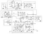
- FIG. 3illustrated is a schematic diagram of an embodiment of a power converter including a control system constructed according to the principles of the present invention.
- the schematic diagram illustrated in FIG. 3illustrates a control system with portions thereof formed as an integrated circuit for an exemplary variable-frequency LLC power train 301 .
- the schematic diagram illustrated in FIG. 3includes processes to provide multiple functional uses of a circuit node such as single pin (e.g., a feedback node or pin FB).
- a controller 304 as described hereinbelowcontrols an operation of the power trains 301 of the power converter.
- the power train 301is formed with transformer T 2 with primary windings P 1 , P 2 , P 3 and secondary windings S 1 , S 2 .
- a bias startup circuit 302is coupled to hot and neutral lines H, N, of ac mains to a capacitor C 8 through the high resistance of a resistor R 8 to provide a startup voltage for a bias voltage source VCC.
- a threshold voltagesuch as 16 volts
- a comparator U 24produces a signal (an under-voltage lockout “UVLO”) that enables power switch control signals DRV_A, DRV_B to be generated by the controller.
- the power switch control signals DRV_A, DRV_Bare coupled to high-side and low-side driver 307 to initiate switching operation of the power train 301 .
- High-side and low-side driver 307produces gate-drive signals HDRV, LDRV for the power switches Q 1 , Q 2 .
- the switching action of the power train 301provides an ongoing energy source for the bias voltage source VCC from the primary windings P 2 , P 3 .
- An internal five volt linear regulator 314 coupled to the bias voltage source VCCproduces an internal regulated bias voltage source VREF.
- a capacitor C 5filters high-frequency components from the regulated bias voltage source VREF, and provides stability for the linear regulator 314 .
- the power converter illustrated in FIG. 3includes an output voltage sensing circuit 309 that produces signals opto_LED 1 , opto_LED 2 that are coupled to the input of an opto-isolator U 6 in opto-isolator circuit 305 .
- the opto-isolator circuit 305produces a feedback signal at the feedback node FB for the controller 304 to enable regulation of a power converter output signal or characteristic (e.g., an output voltage VOUT).
- the power converteralso includes a resistor-capacitor (“RT”) timing circuit 306 with a soft-start circuit 310 .
- RTresistor-capacitor
- a current produced by a current source I 1(or, in an alternative embodiment, a current sink) is applied within the controller 304 to the feedback node FB to enable multiple functional uses thereof.
- the amount of current produced by the current source I 1is designed to be low compared with the current that would otherwise flow through any impedances that would typically be connected to that node FB.
- the current source I 1is switched ON and OFF with a timing signal TOFF inside the controller 304 .
- a timing signal TON produced by a timing clock U 12 coupled to the timing circuit 306is inverted by an inverter U 16 to produce the timing signal TOFF.
- the values of the current source I 1are ten microamperes (“ ⁇ A”) when the timing signal TOFF is high and zero amperes when the timing signal TOFF is low.
- the voltage appearing on the feedback node FBis equal to the voltage across the resistor R 5 when the timing signal TOFF is low and is equal to the voltage across the resistor R 5 plus one volt when the timing signal TOFF is high.
- the voltage differential of one voltcan be changed external to the controller by changing the value of the resistor R 23 .
- a circuit (a non-latching shutdown circuit) 312 illustrated in FIG. 3is configured to produce a non-latching shutdown (e.g., a “hiccup”) mode of operation when the voltage of the feedback node FB exceeds about 3.7 volts (a threshold, “3V7”) by turning ON a switch Q 16 , which shorts the bias voltage source VCC to local circuit ground through a resistor R 31 (e.g., 100 ohms).
- a non-latching shutdowne.g., a “hiccup”
- a circuit (a latching shutdown circuit) 311is configured to produce a latching shutdown mode of operation when the voltage of the feedback node FB exceeds 4.7 volts (a threshold, “4V7”) by turning ON a pair of switches Q 19 , Q 20 , which emulates a thyristor.
- the pair of switches Q 19 , Q 20also shorts the bias voltage source VCC to local circuit ground through the resistor R 31 .
- Continuing current supplied by the bias startup circuit 302provides sufficient current to maintain the pair of switches Q 19 , Q 20 in a latched-ON state.
- the power converterwill shut down and latch off until the ac mains is removed.
- the latched-off statequickly resets since the voltage across the capacitor C 8 is very low (equal to the ON-state voltage of the thyristor formed by the pair of switches Q 19 , Q 20 ) prior to removal of the ac mains, and there is no other substantial source of stored energy in the path that holds the pair of switches Q 19 , Q 20 in the ON state.
- the feedback node FBgenerates a current through a voltage controlled current source G 1 that is proportional thereto minus an offset of approximately 1.2 volts produced by an emitter follower Q 5 and the base-emitter drop inside the current mirror that is used to create the voltage controlled current source G 1 .
- This currentwhich is a function of the feedback voltage at the feedback node FB, modulates the current into a timing capacitor C 1 coupled to a circuit node or pin CT during the ON time of the gate drives (that is, when the timing signal TON is high and the timing signal TOFF is low).
- the 1.2 voltage offsetallows for an external setting of the opto-isolator bias current through the choice of the resistor R 5 .
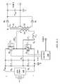
- FIG. 4illustrated is a schematic diagram of an embodiment of an opto-isolator circuit employable with the power converter of FIG. 3 constructed according to the principles of the present invention.
- the opto-isolator circuitincludes a Zener diode ZD 400 across a resistor R 5 to limit the frequency range of the LLC power stage.
- a Zener diode ZD 401represents an alternative Zener diode location to limit the frequency range of the LLC power stage. If the bias voltage source VCC is fixed, the frequency range of the LLC power stage can be limited by placing a resistor between the collector of the opto-isolator circuit and the bias voltage source VCC.
- the collector of the opto-isolator U 6may be coupled to the regulated bias voltage source VREF rather than to the bias voltage source VCC. Limiting the frequency range in either of these ways prevents the opto-isolator U 6 from activating either type of fault. Fault handling in the controller would then employ a separate opto-isolator.
- an internal comparator U 4transitions the controller 304 into a low power mode of operation when the feedback voltage exceeds approximately 2.1 volts [a threshold based on 1.4 V+VBE_Q 5 ].
- the low power mode of operationdisables the timing of a switch Q 4 on the RT pin and causes the OFF time of the gate drives to become very large as determined by an external resistor R 13 in the timing circuit 306 .
- the feedback level at which the controller comes out of its low power modeis determined by the 2.1 volt threshold described above as well an offset produced by the external resistor R 23 placed in series with the feedback node or pin FB in the opto-isolator circuit 305 .
- the current source I 1that may be formed with a current mirror and a resistor in a conventional manner and controlled by the timing signal TOFF injects a square wave of current into the feedback node FB.
- An exemplary injected current amplitudewould be approximately ten microamperes, which produces a square-wave offset voltage of about the same. Since the resistance of the resistor R 5 (e.g., one kilo-ohm “k ⁇ ”) is typically much lower than the resistance of resistor R 23 (e.g., 100 kilo-ohms) the effect of the ten microampere injected current on the voltage across the resistor R 5 is negligible.
- the current source I 1 that produces the currentis turned off by a switch S 2 during the ON time of the gate drives. What results is a superimposed square wave voltage at the feedback node FB of the controller 304 .
- Logic coupled to the comparator U 4 for the controller 304transitions the same into a low power mode when the feedback voltage at the opto-isolator emitter rises above 2.1 volts, but gates the controller 304 out of the low power mode after the feedback voltage at the opto-isolator emitter falls below about 1.1 volts.
- the one volt hysteresis bandis settable by changing the resistance value of the external resistor R 23 .
- the process to make multifunctional use of the feedback node FBadvantageously includes turning a low value current source (or sink) ON and OFF in synchronization with a clock oscillator and injecting the current produced by the current source I 1 into a circuit node such as the feedback node FB that is used to sense a voltage.
- the gating of a condition within the controller 304is also timed to coincide with the gating of the current source I 1 so that a band of hysteresis is created that can be externally set with a single resistance value (e.g., the resistance of resistor R 23 ).
- the processthus allows for an increase in the number of externally settable parameters for the controller 304 without increasing a pin count.
- the processcan also be used to increase the number of sensed parameters to three rather than two by using both a current source and a current sink that are turned ON and OFF in synchronization with the controller 304 .
- a signal LLC_RUN that is an enabling signal for the overall operation of the power converteris produced by logic U 13 .
- This signal LLC_RUNis generally produced by logic U 3 that is tailored for a particular power converter design, and will not be further described herein in the interest of brevity.
- internal reference voltagessuch as “4V7,” “3V7,” etc., representing voltage sources with respective voltages of 4.7 volts, 3.7 volts, etc., are conventionally produced by small internal dissipative regulators and/or voltage dividers coupled to the bias voltage sources VCC, VREF, and will also not be further described herein in the interest of brevity.
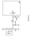
- FIG. 5illustrated is a schematic diagram of an embodiment of an opto-isolator circuit employable with the power converter of FIG. 3 constructed according to the principles of the present invention.
- a current source CS 1 and a current sink CS 2are turned ON and OFF by switches 503 , 504 in synchronization with a timing signal TON, which is the inverse of the timing signal TOFF.
- a delay flip-flop 507is coupled to the timing signal TON to produce signals 505 , 506 employing AND gates 508 , 509 to switch between current source CS 1 and current sink CS 2 based on the state of the delay flip-flop 507 .
- a one microampere currentmay be injected from the current source CS 1 into the feedback node FB at one time, no current at another time, and then sink a one microampere current into the current source CS 2 at a third time.
- diodes 501 , 502 in series with external resistors R 23 A, R 23 Bthe combination of which is in series with the feedback node FB would thus lead to a third signal level.
- ones of the diodese.g., diode 502
- the processdoes not have to be used to change the state of the controller 304 (for example from standard operation to low power mode).
- the processcan also be used for other purposes such as to read voltage levels for analog purposes (e.g., such as for charging an external capacitor in a given amount of time).
- This example of multiple functional use of the feedback node FBcould also be employed to set a time limit (or integrated power limit) for short-term over-current protection, for example, in printer power supplies, without using an additional integrated circuit node or pin.
- a controller 304may be formed as an integrated circuit for a power converter.
- the power convertermay be constructed as an LLC power stage.
- the controller 304is constructed with a feedback node FB configured to alter a gate drive signal [HDRV or LDRV] for a power switch [Q 2 or Q 1 ] in the power converter.
- a current source I 1 in the controller 304is coupled to the feedback node FB.
- the current source I 1may be selectively turned ON in synchronization by a timing signal (a clock signal) TOFF in the controller 304 (to produce a square-wave voltage at the feedback node FB).
- a resistor R 23is coupled between the feedback node FB and a feedback control signal [such as the feedback current control signal produced by opto-isolator U 6 ].
- a comparator U 4is coupled to the feedback node FB.
- the comparator U 4is configured to produce a signal to control a function of the power converter in response to a voltage produced at the feedback node FB by the selectively enabled current source I 1 .
- the selectively enabled current source I 1may alter the feedback control signal to accommodate a low power mode of the power converter.
- the selectively enabled current source I 1creates a hysteresis band to prevent oscillating between the low power mode and a standard power mode of the power converter.
- the controller 304may further include a comparator [U 11 or U 14 ] as part of one of the circuits 311 , 312 configured to transition the controller 304 to another operational mode of the power converter, such as a latching or non-latching shutdown mode, in response to the voltage produced at the feedback node FB by the current source I 1 .
- the comparatormay be employed in addition to or in lieu of the selectively enabled current source I 1 .
- a Zener diodee.g., ZD 400
- ZD 400may be coupled to the feedback control signal to provide a limit for an operational characteristic of the controller 304 such as a switching frequency.
- the controllermay further include another current source that is selectively turned ON in synchronization with the timing signal TOFF and another comparator configured to control another function of the power converter in response to a voltage produced at the feedback node FB by the another selectively enabled current source.
- the another selectively enabled current sourcemay be selectively turned ON in synchronization with a sub-multiple of the timing signal TOFF such as a sub-multiple clock signal produced by a T (toggle) flip-flop coupled to the timing signal TOFF.
- Additional pinsare also conventionally added to a controller formed as an integrated circuit to enable additional parameters to be set related to timing conduction of power switches.
- an oscillator function of the controlleris formed with a charge/discharge source connected to an external resistor and capacitor.
- a sense node or pinis coupled to the external capacitor that senses the voltage on the external capacitor, and another pin is employed to provide another coupling to the external resistor. This allows a single controller parameter to be set through external components.
- two changesare made to a conventional circuit to enable several parameters to be externally set for the controller using the same two pins. The first change involves enabling a charge/discharge pin also go to a tri-state value during certain modes of operation of the controller.
- tri-staterefers to a circuit condition wherein a signal line is open circuited, and pulled neither high nor low.
- the second changeinvolves gating the information from the feedback control node or pin FB, a third pin, to draw current through the external timing capacitor C 1 during a charge or discharge cycle, but preferably not both.
- FIG. 3illustrates an example of a controller 304 that may be formed as an integrated circuit and an external circuit connected thereto.
- the controller 304produces switch control signals DRV_A, DRB_B coupled to a high-side and low-side driver 307 for a variable-frequency LLC power stage 301 .
- An oscillator section of the controller 304 that produces the timing signals TON, TOFFis coupled to two nodes (or pins) labeled RT and CT as illustrated in FIG. 3 .
- the pin labeled CTmonitors voltage across the timing capacitor C 1 while the pin RT causes a charge/discharge of the timing capacitor C 1 by going high, low, or tri-state.
- the external timing networkincludes the timing capacitor C 1 , timing resistors R 1 , R 22 , R 13 , and diode D 1 .
- the soft-start circuit 310is also included in the timing circuit 306 .
- the timing capacitor C 1When a voltage on the pin RT is high, the timing capacitor C 1 charges through series-coupled resistors (charge/discharge resistors) R 1 , R 22 . Due to the presence of the diode D 1 , when the voltage on the pin RT is low, the timing capacitor C 1 discharges through the resistor R 1 . The resistor R 22 has negligible effect. When the circuit coupled to the pin RT is tri-state (e.g., when the switches Q 4 , Q 11 are both disabled to conduct), the timing capacitor C 1 slowly discharges through resistor R 13 .
- the resistor R 13is always in the circuit regardless of the state of the circuit coupled to the pin RT, in practice, the resistor R 13 has negligible effect when the circuit coupled to the pin RT is not tri-state since the resistances of resistors R 1 , R 22 are significantly smaller than the resistance of resistor R 13 .
- the voltage of the feedback node FBis translated to a current inside the controller 304 by voltage controlled current source G 1 . This current increases the charging rate of the timing capacitor C 1 to change the ON time of the switch control signals (or gate drive signals).
- the switch S 3shuts off the current source G 1 (which is increasing the charging rate) during the discharge of the timing capacitor C 1 (corresponding to the OFF time (or dead-time) of the gate drive signals).
- the voltage on the feedback node FBtherefore, only affects the ON time of the power switches Q 1 , Q 2 , not the OFF time.
- the controller 304switches into a low power mode.
- the circuit coupled to the pin RTis tri-stated during the OFF time of the power switches Q 1 , Q 2 .
- the length of the OFF timeis determined by the resistance of resistor R 13 , and is significantly longer than the OFF time that would normally be used.
- the timing signal TOFF800 nanoseconds (“ns”) and the timing signal TON might vary from four microseconds (“ ⁇ s”) to 12 ⁇ s as the load varies.
- the OFF timemight be changed to one millisecond (“ms”). As described by Jungreis, et al. cited above, changing the OFF time to on the order of one millisecond reduces losses at very low power levels.
- the normal operation ON time, normal operation OFF time, and low power OFF timecan be set with external resistors using two integrated circuit nodes or pins RT, CT. Furthermore, since the feedback voltage threshold for transitioning to a low power mode is fixed internal to the controller 304 and corresponds to a fixed level of timing current being supplied to the external timing capacitor C 1 , the gate drive ON time at which the controller 304 enters low power mode can be changed by adjusting the value of the timing capacitor C 1 . The ability to externally set the OFF time is important since it allows tuning a resonant tank to have substantially zero-voltage switching regardless of a transformer leakage inductance.
- a controller 304may be formed as an integrated circuit for a power converter (e.g., a power converter constructed with an LLC power stage).
- the controller 304is constructed with two nodes or pins, a first node CT and a second node RT.
- a capacitor C 1is coupled to the first node CT.
- a comparator U 12is also coupled to the first node CT, and the comparator U 12 is configured to control a power switch of the power converter.
- the second node RTis coupled to the first node CT through a resistor-diode network (a timing circuit 306 ).
- a first switch Q 11is coupled to the second timing node RT.
- the first switch Q 11is configured to couple the second node RT to a bias voltage source, and the second node RT is configured to charge the timing capacitor C 1 through a resistor R 22 in the timing circuit 306 when the second node RT is coupled to the bias voltage source by the first switch Q 11 .
- a second switch Q 4is also coupled to the second node RT.
- the second switch Q 4is configured to couple the second node RT to a second voltage level, local circuit ground.
- the second node RTis configured to discharge the capacitor C 1 through a resistance R 1 in the timing circuit 306 when the second node RT is coupled to the second voltage level by the second switch Q 4 .
- the bias voltage sourceis brought out of the controller 304 (i.e., if the bias voltage source is duplicated external thereto through a linear regulator) one can flip the resistor-capacitor-diode network shown in the timing circuit 306 as well as flip the logic.
- the second node RTis raised to five volts to charge the timing capacitor C 1 when the timing signal TON is enabled. Pulling the second node RT to zero volts discharges the timing capacitor C 1 when the timing signal TOFF is enabled.
- the large resistance resistor R 13discharges the timing capacitor C 1 to local circuit ground. Since local circuit ground is generally available, this is a convenient arrangement to allow slow capacitor discharge in the tri-state.
- the second node RTwould be dropped to zero volts to discharge the timing capacitor C 1 , corresponding to when the timing signal TON is enabled.
- the second node RTbeing raised to five volts would charge the timing capacitor C 1 , corresponding to when the timing signal TOFF is enabled.
- a disadvantage with this direction of the charge/discharge of the timing capacitor C 1is that a tri-state does not allow a slow discharge of the timing capacitor C 1 unless the resistor R 13 is connected to five volts rather than to local circuit ground.
- the resistor R 13cannot be connected to five volts unless either the bias voltage source is externally available on the integrated circuit, or another five voltage supply is created such as by using a five voltage Zener diode or a linear regulator after the bias voltage source.
- the controller 304is further constructed to operate the first and second switches Q 11 , Q 4 coupled to the first node CT in a tri-state mode in response to an internal signal, wherein the first switch Q 11 and the second switch Q 4 are both disabled to conduct, enabling the timing capacitor C 1 to be discharged through a third resistance R 13 .
- the internal signalis generated by a comparator [U 11 or U 14 ] sensing a voltage produced by a feedback control signal coupled to a feedback node or pin FB exceeding a threshold voltage level to signal the controller 304 to operate in a low power mode.
- a Zener diode ZD 400may be coupled to the feedback control signal to provide a limit for an operational characteristic of the controller 304 , such as a switching frequency.
- Ac-dc power suppliestypical require the secondary side of the circuit to transmit fault information (e.g., overvoltage protection “OVP” and overcurrent protection “OCP” signals) to a controller to latch off the operation of the power converter or to initiate an auto-restart mode.
- fault informatione.g., overvoltage protection “OVP” and overcurrent protection “OCP” signals
- Transmitting fault information across the primary-secondary isolation boundaryusually entails adding a second opto-isolator in addition to a first opto-isolator used for the feedback signal. Adding a second opto-isolator to the design of a controller takes up additional space and cost.
- the integrated circuit for the controller 304is generally formed with comparators coupled to a feedback node or pin FB.
- a voltage of the feedback node FBexceeds a level expected in a normal feedback range, it trips fault logic in the integrated circuit.
- the lower levelinitiates a non-latching fault, wherein the operation of the power converter is restarted when the voltage of the feedback node FB falls below the lower level, and a “wait” time has expired.
- the higher levelinitiates a latching fault that generally requires removal of input power to the power converter for a sufficient period of time to reset.
- FIG. 3illustrates an example of an integrated circuit formed with an opto-isolator circuit 305 employed to transmit a feedback signal across the primary-secondary isolation boundary.
- the controller 304produces gate drive signals HDRV, LDRV for the variable-frequency LLC power train 301 .
- the feedback signal from the output of the opto-isolator circuit 305is coupled to the feedback node FB.
- the feedback node FBcan generate a response to two types of fault shutdowns. When the voltage on the feedback node FB exceeds approximately 3.7 volts, the output of comparator U 11 goes high, which initiates a hiccup mode (i.e., a non-latching fault mode).
- the gate drivesare disabled and at the same time, switch Q 16 turns ON, drawing down the bias voltage source VCC.
- the switch Q 16is turned off, thus allowing the external high-voltage current source (or resistor) to recharge the bias voltage source VCC.
- the hysteresis designed into the UVLOe.g., the controller 304 turns ON at 16 volts but operates down to ten volts) will cause a substantial delay for the controller 304 to turn back ON after the fault is cleared.
- the gate drive signals HDRV, LDRVwill stay ON for a short time followed by a long period of being OFF, which is often referred to as a hiccup mode.
- the power converterautomatically restarts, since this is a non-latching fault.
- the feedback node FBis responsive to a second type of fault shutdown. If the voltage of the feedback node FB exceeds 4.7 volts, a thyristor formed by the pair of switches Q 19 , Q 20 draw down the voltage of the bias voltage source VCC and continue to hold the voltage of the bias voltage source VCC down while there is any current flowing thereto, which can be sourced by the bias startup circuit 302 .
- the non-latching fault inputalready described disables the gate drive signals HDRV, LDRV while the fault on the feedback node FB exceeds 3.7 volts.
- the gate drive signals HDRV, LDRVare disabled and the thyristor formed by the pair of switches Q 19 , Q 20 will turn ON, holding down the voltage of the bias voltage source VCC.
- the switch Q 11draws down the voltage of the bias voltage source VCC until the UVLO signal goes low.
- the thyristordraws down the voltage of the bias voltage source VCC as long as there is any holding current in the thyristor.
- the bias startup circuit 302that is designed to provide startup power to the controller 304 provides the holding current for the thyristor. If the bias voltage source VCC is connected to a rectified input line via a high-voltage current source or by a resistor, the controller 304 will remain latched off until the power converter is disconnected from the ac mains for a sufficient period of time (e.g., to discharge the capacitor C 8 ), and is then reconnected.
- the secondary-side fault outputis connected to a switch (switch Q 21 in FIG. 3 ) and series resistor R 45 to draw a large amount of current through the opto-isolator circuit 305 .
- the high level of current through the opto-isolator circuit 305causes the feedback node FB to rise to a sufficiently high voltage to trip the fault circuitry inside the controller 304 as described above. If the voltage of the feedback node FB is allowed to rise to any value, then the latching fault will be initiated when there is a fault.
- Zener diodee.g., 4.2 volt Zener diode
- the opto-isolator circuit 305that is already used to provide a feedback signal to the feedback node FB to regulate an output signal or characteristic of the power converter such as the output voltage VOUT can therefore also be used to provide latching or non-latching fault capability for the power converter. Whether the fault is latching or non-latching can be set externally by the presence or absence of a Zener diode on the feedback node FB.
- a controller 304may be formed as an integrated circuit for a power converter.
- the controller 304is constructed with a feedback node FB configured to receive a feedback control signal from an opto-isolator circuit 305 to produce a control signal for a power switch in the power converter.
- the power convertermay be constructed, without limitation, as an LLC power stage or a pulse-width modulated (“PWM”) power converter.
- a comparator U 11is coupled to the feedback node FB, and the comparator U 11 is configured to enable a first mode of operation for the power converter (e.g., a non-latching shutdown mode) when a voltage to the comparator U 11 produced at the feedback node FB exceeds a first threshold voltage.
- a selectively switched current source, resistor R 45 , switch Q 21may be coupled to the opto-isolator circuit 305 , and the selectively switched current source may be employed to selectively produce a level of current in the opto-isolator circuit 305 sufficient to trip the comparator U 11 .
- the controller 304further includes a comparator U 14 coupled to the feedback node FB, and the comparator U 14 is configured to enable a second mode of operation for the power converter (e.g., a latching shutdown mode), when a voltage to the comparator U 14 produced at the feedback node FB exceeds a second threshold voltage.
- a Zener diode ZD 400may be coupled to the feedback control signal to prevent the voltage to the comparator U 14 produced at the feedback node FB from exceeding the second threshold voltage.
- a Zener diode ZD 401may be placed directly across the feedback node FB to prevent the voltage to the comparator U 14 produced at the feedback node FB from exceeding the second threshold voltage. Inclusion of the Zener diode prevents the comparator from enabling the second mode of operation.
- a control systemmay include, without limitation, a controller, opto-isolator circuit, timing circuit, bias startup circuit, output voltage sensing circuit and a driver.
- any circuit that assists in the management or control of a power train of a power convertermay be incorporated into a controller or control system.
Landscapes
- Engineering & Computer Science (AREA)
- Power Engineering (AREA)
- Dc-Dc Converters (AREA)
Abstract
Description
This application claims the benefit of U.S. Provisional Application No. 61/314,900, entitled “Controller for a Power Converter and Method of Operating the Same,” filed on Mar. 17, 2010, which application is incorporated herein by reference.
The present invention is directed, in general, to power electronics and, more specifically, to a power converter employing a control system configured to make multiple operational use of a circuit node therein and method of operating the same.
A switched-mode power converter (also referred to as a “power converter” or “regulator”) is a power supply or power processing circuit that converts an input voltage waveform into a specified output voltage waveform. Dc-dc power converters convert a direct current (“dc”) input voltage into a dc output voltage. Controllers associated with the power converters manage an operation thereof by controlling conduction periods of power switches employed therein. Some power converters include a controller coupled between an input and output of the power converter in a feedback loop configuration (also referred to as a “control loop” or “closed control loop”) to regulate an output signal or characteristic of the power converter. Typically, the controller measures the output characteristic (e.g., an output voltage, an output current, or a combination of an output voltage and an output current) of the power converter, and based thereon modifies a duty cycle which can be an ON time or a switching frequency of a power switch of the power converter to regulate the output characteristic. Other power converters operate in an open-loop manner wherein an output voltage is produced substantially proportional to an input voltage.
The number of physical input pins on integrated circuits (“ICs”) such as mixed-signal integrated circuits that embody a controller for a power converter typically sense a single analog voltage level entering the integrated circuit, and are limited to adjustment of only one internal signal level by that analog voltage level through external components. Occasionally, there is also a logic function associated with these input pins as well, but only a single voltage level sense. Thus, additional pins are conventionally added to an integrated circuit to provide additional voltage inputs for an internal signal that is utilized by the controller. However, the additional integrated circuit pins are expensive, especially when exceeding a typical package limit (e.g., changing from 16 to 17 or more pins). It is highly advantageous from a manufacturing cost perspective to maintain a standardized pin arrangement.
Accordingly, what is needed in the art is a design approach and related method for a control system for a power converter that enables multiple functional use of an integrated circuit input pin without compromising product performance, and that can be advantageously adapted to high-volume manufacturing techniques without adding significant cost. A further need in the art is elimination of an opto-isolator by sharing an opto-isolator (e.g., a feedback opto-isolator) with another opto-isolator (e.g., a fault opto-isolator) in the power converter.
These and other problems are generally solved or circumvented, and technical advantages are generally achieved, by advantageous embodiments of the present invention, including a power converter employing a control system configured to make multiple functional use of a circuit node therein and method of operating the same. In one embodiment, the power converter includes a power train including at least one power switch. The power converter also includes a control system including an opto-isolator circuit, including a resistor, configured to receive an output signal from the power converter and provide a feedback signal to a feedback node for the control system to provide a switch control signal for the at least one power switch. The control system also includes a current source configured to produce multiple voltage levels at the feedback node in accordance with the resistor, thereby enabling multiple functional uses of the feedback node.
The foregoing has outlined rather broadly the features and technical advantages of the present invention in order that the detailed description of the invention that follows may be better understood. Additional features and advantages of the invention will be described hereinafter, which form the subject of the claims of the invention. It should be appreciated by those skilled in the art that the conception and specific embodiment disclosed may be readily utilized as a basis for modifying or designing other structures or processes for carrying out the same purposes of the present invention. It should also be realized by those skilled in the art that such equivalent constructions do not depart from the spirit and scope of the invention as set forth in the appended claims.
For a more complete understanding of the present invention, reference is now made to the following descriptions taken in conjunction with the accompanying drawings, in which:
Corresponding numerals and symbols in the different figures generally refer to corresponding parts unless otherwise indicated, and may not be redescribed in the interest of brevity after the first instance. The FIGUREs are drawn to illustrate the relevant aspects of exemplary embodiments.
The making and using of the present exemplary embodiments are discussed in detail below. It should be appreciated, however, that the present invention provides many applicable inventive concepts that can be embodied in a wide variety of specific contexts. The specific embodiments discussed are merely illustrative of specific ways to make and use the invention, and do not limit the scope of the invention.
The present invention will be described with respect to exemplary embodiments in a specific context, namely, a power converter employing a control system configured to provide multiple functional use of a circuit node (e.g., a pin such as a pin of an integrated circuit), or to eliminate a need for an added opto-isolator for fault reporting or other purposes. While the principles of the present invention will be described in the environment of a power converter, any application that may benefit from a control system as described herein including, without limitation, a bias supply, a power amplifier, or a motor controller is well within the broad scope of the present invention.
A resonant full-bridge or half-bridge power converter or other resonant power converter topology with a substantially symmetric input current waveform may be employed in low and medium power applications such as in a power adapter for a printer because of its low cost and high power conversion efficiency at power levels of interest for these applications. Power converters are typically designed to operate continuously at their full rated output power level.
Turning now toFIG. 1 , illustrated is a schematic diagram of an embodiment of a power converter (e.g., a resonant half-bridge dc-dc power converter) constructed according to the principles of the present invention. The power converter illustrated inFIG. 1 can be operated as a variable-frequency inductor-inductor-capacitor (“LLC”) resonant power stage or as a zero-voltage switched quasi-resonant power stage, and is similar to the power converter described in U.S. patent application Ser. No. 12/642,448, entitled “Controller for a Power Converter,” to Jungreis, et al., filed Dec. 18, 2009, which is incorporated herein by reference.
The power converter includes first and second power switches Q1, Q2in series with a dc bus (at an input of the power converter) produced by a dcinput voltage source 110, represented inFIG. 1 by a battery, and filtered by an electromagnetic interference (“EMI”)filter 120. First and second switch capacitors CQ1, CQ2represent capacitances of the first and second power switches Q1, Q2, respectively, or alternatively, discrete capacitors optionally included in the power converter to retard voltage changes across the first and second power switches Q1, Q2. TheEMI filter 120 provides a substantially filtered dc bus voltage or input voltage Vbusto a magnetic device (e.g., an isolating transformer or transformer T1). Typically, the dcinput voltage source 110 would be produced by a bridge rectifier or by a power-factor correction stage. Although theEMI filter 120 illustrated inFIG. 1 is positioned between the dcinput voltage source 110 and the half-bridge capacitor voltage divider formed by first and second divider capacitors C4, C5, theEMI filter 120 may contain filtering components positioned elsewhere in the power converter.
The transformer T1, coupled to the first and second power switches Q1, Q2, has a primary winding P1, and first and second secondary windings S1, S2 with a turns ratio n:1:1 that is selected to provide an output signal or characteristic (e.g., an output voltage VOUT) with consideration of the range of the input voltage Vbusand stress on the power train of the power converter. A resonant full-bridge dc-dc power converter may be formed with two power switches substituted for the first and second divider capacitors C4, C5. Each of the added power switches in a full-bridge configuration would be switched substantially synchronously with a diagonally oriented power switch.
The first and second power switches Q1, Q2(e.g., n-channel field-effect transistors) are controlled by a controller (or control system)140 that produces switch control signals (e.g., gate-drive signals HDRV, LDRV) to control the first and second power switches Q1, Q2to conduct for controlled intervals of time (i.e., for controlled “ON” times). The term “signal” is used herein to represent, without limitation, a physical voltage or current. The first and second power switches Q1, Q2alternately conduct in response to the gate-drive signals HDRV, LDRV (e.g., gate-drive voltages) produced by thecontroller 140 with a switching frequency (designated “fs”) and a corresponding switching period Ts=1/fs. The ac voltage appearing or present on the first and second secondary windings S1, S2 of the transformer T1is rectified by first and second diodes D1, D2, and the dc component of the resulting waveform is coupled to the output through the low pass output filter formed with output filter capacitor Coutto produce the output voltage VOUT. Thecontroller 140 senses the output voltage VOUT to regulate the ON time of the first and second power switches Q1, Q2. The OFF time of the first and second power switches Q1, Q2may also be adjusted as a function of a current or a power level of the power converter to reduce power converter losses as described by Jungreis, et al., cited previously hereinabove.
The power converter is operated as a resonant half-bridge topology. The term “resonant” is employed herein to refer to a switch-mode topology employing a resonant tank circuit or resonant circuit formed principally by a resonant capacitor C1and a resonant inductor Lresto produce a current waveform that is a portion of, but may not be a full, sinusoidal waveform. The resonant circuit is series-coupled to the transformer T1. The circuit node between first and second divider capacitors C4, C5substantially remains at a voltage approximately equal to half of the input voltage Vbuswith respect to a primary ground, which is identified with the symbol “p.” The secondary ground is identified with the symbol “s.” The source of second power switch Q2is coupled to the primary ground p.
The resonant capacitor C1and the first and second divider capacitors C4, C5are coupled together at common circuit node N0. The first and second divider capacitors C4, C5are roughly equal in capacitance and the combination is generally larger in capacitance than that of the resonant capacitor C1. Such a structure provides symmetry from an EMI perspective for high frequency currents fed back to the dcinput voltage source 110, and also provides a relatively unvarying voltage at the common circuit node N0. In an alternative embodiment, one or both of the resonant capacitor C1and the first divider capacitor C4can be omitted from the power converter. If both the resonant capacitor C1and the first divider capacitor C4are omitted from the power converter, the second divider capacitor C5would be selected with a capacitance similar to that of resonant capacitor C1.
The resonant inductor Lresincludes the leakage inductance of the transformer T1referenced to its primary winding P1. The effective resonant capacitance is Ceff, given by the equation:
Ceff=C1·(C4+C5)/(C1+C4+C5).
Ceff=C1·(C4+C5)/(C1+C4+C5).
The half period Thalfof the resonant circuit, which is the period during which a power switch is turned ON, can be represented approximately by the equation:
Thalf=π·√{square root over (Lres·Ceff)}.
Thalf=π·√{square root over (Lres·Ceff)}.
If a power switch ON times are approximately equal to the half-period Thalfshown above, the power converter operates as a “dc transformer” that produces an output voltage VOUT substantially proportional to the input voltage Vbus. The output-to-input voltage ratio is substantially fixed by the transformer T1turns ratio when it is operated as a dc transformer, and thus the power converter per se does not provide output voltage regulation if the power switch ON times are approximately equal to the half period Thalfshown above. Regulation of the output voltage VOUT in such an arrangement can be provided by a pre-converter stage (not shown) that regulates the input voltage Vbusto the power converter illustrated inFIG. 1 if a power switch ON times are approximately equal to the half period Thalfshown above.
Control (e.g., modification, alteration, variation, etc.) of the switching frequency by varying the ON time of the first and second power switches Q1, Q2can be employed to regulate the output voltage VOUT of the power converter. In an embodiment, the ON time (or conduction periods or a duty cycle) between fixed OFF times of the first and second power switches Q1, Q2may be varied to control the switching frequency to regulate the output voltage VOUT. The dead times between power switch conduction periods and/or the ON times of the first and second power switches Q1, Q2may be substantially equal, but are not required to be so.
At a high input voltage level, the power train may be operated at a switching frequency that is higher than the resonant frequency fresof the resonant circuit. At a high input voltage level, the ON time (often referred to or designated as “Ton”) of each of the first and second power switches Q1, Q2corresponds to an ON time that is equivalent to a frequency that is a higher than the resonant frequency of the resonant circuit. In other words, the ON time for each of the first and second power switches Q1, Q2is a little shorter than the half period Thalfof the resonant circuit, and together the first and second power switches Q1, Q2are ON for a period of time that is a little shorter or less than twice the half period Thalf. The ON times of the first and second power switches Q1, Q2are preferably, but not necessarily, equal. Thus, the first and second power switches Q1, Q2are turned OFF before the time that the current in the resonant circuit reaches zero, and the switching period is kept short enough and the dead-time between alternate switch conduction times long enough to assure that, throughout the tolerance band of variations of power converter inductances and capacitances, the current through a controlled switch on a primary side of the power converter will shift to an anti-parallel diode (or body diode) of the power switch that is about to be turned ON (or prior to turning ON the same) or that the resonant current has decayed to approximately zero. The body diodes of the first and second power switches Q1, Q2are designated DBD1, DBD2, respectively. Thus, a variable ON time is employable in a power converter such as a resonant bridge power converter to regulate the output voltage VOUT.
In U.S. patent application Ser. No. 12/486,520, entitled “Power Converter Employing a Variable Switching Frequency and a Magnetic Device with a Non-Uniform Gap,” to A. Brinlee, et al., filed Jun. 17, 2009, which is incorporated herein by reference, a switching frequency of a power switch of a power converter is controlled as a function of a condition of the power converter representing an output power. Also, a duty cycle of the power switch(es) is controlled to regulate an output characteristic of the power converter such as the output voltage. The ON time of the power switches may be controlled (e.g., slightly modulated) to reduce or cancel a ripple voltage (e.g., a 120 hertz ripple voltage) of an input voltage source such as an upstream power converter (e.g., a power factor correction converter) to the power converter employing the power switches.
Turning now toFIGS. 2A and 2B , illustrated are graphical representations of exemplary performance characteristics of a power converter according to the principles of the present invention.FIG. 2A illustrates a switching frequency fsof an LLC power stage as a function of power converter output power. As output power increases, the switching frequency fsof the power converter decreases.FIG. 2B illustrates an opto-isolator output current Ioptoin a controller feedback loop for an LLC power stage, represented by theline 202, as a function of power converter output power. When output power falls below a lower power threshold, such as the lower power threshold represented by the vertical dashed line at the power level of three watts (“W”), the power converter may be transitioned to a low power mode, wherein dead time between the ON time(s) of the power switches is increased to reduce power converter losses. When the power converter is operated in such a low power mode, the opto-isolator output current Ioptofalls somewhat to a lower current level, as represented by theline 203, to preserve regulation of output voltage. Ideally, as introduced herein, to preserve output voltage regulation without an unnecessary transient in the output voltage, the controller executes a corrective action to transition between thelines
Thus, the OFF times of the power switches (such as the first and second power switches Q1, Q2illustrated with respect toFIG. 1 ) may be increased as the load is decreased, such as indicated by a transient increase of the output voltage of the power converter, which causes the switching frequency of the power converter to decrease at light loads. The decrease in switching frequency decreases switching losses. In an alternative design, the ON times of the power switches (such as the first and second power switches Q1, Q2illustrated with respect toFIG. 1 ) may be decreased as the load is decreased, which causes the switching frequency of the power converter to increase at light loads. Exemplary dead times are advantageously increased for loads below a chosen load point such as three watts so that the power losses are reduced at low load levels, and conduction and switching-loss trade-offs can be made for the power converter.
The input pins on mixed signal integrated circuits such as an integrated circuit embodying a controller for an LLC power stage typically sense a single analog voltage level entering the integrated circuit, and are limited to an adjustment of one internal level by that analog voltage level through external components. An integrated circuit embodying a controller is generally formed as an application specific integrated circuit (“ASIC”), and will be generally referred to herein as an integrated circuit. Occasionally, there is also a logic function associated with these pins as well, but only a single voltage level sense. Thus, additional pins, which are generally expensive, are conventionally added to an integrated circuit to provide additional voltage inputs for an internal signal.
Turning now toFIG. 3 , illustrated is a schematic diagram of an embodiment of a power converter including a control system constructed according to the principles of the present invention. The schematic diagram illustrated inFIG. 3 illustrates a control system with portions thereof formed as an integrated circuit for an exemplary variable-frequencyLLC power train 301. The schematic diagram illustrated inFIG. 3 includes processes to provide multiple functional uses of a circuit node such as single pin (e.g., a feedback node or pin FB). Acontroller 304 as described hereinbelow controls an operation of thepower trains 301 of the power converter.
Thepower train 301 is formed with transformer T2 with primary windings P1, P2, P3 and secondary windings S1, S2. Abias startup circuit 302 is coupled to hot and neutral lines H, N, of ac mains to a capacitor C8 through the high resistance of a resistor R8 to provide a startup voltage for a bias voltage source VCC. When the voltage of the bias voltage source VCC is greater than a threshold voltage, such as 16 volts, a comparator U24 produces a signal (an under-voltage lockout “UVLO”) that enables power switch control signals DRV_A, DRV_B to be generated by the controller. The power switch control signals DRV_A, DRV_B are coupled to high-side and low-side driver 307 to initiate switching operation of thepower train 301. High-side and low-side driver 307 produces gate-drive signals HDRV, LDRV for the power switches Q1, Q2. The switching action of thepower train 301 provides an ongoing energy source for the bias voltage source VCC from the primary windings P2, P3. An internal five voltlinear regulator 314 coupled to the bias voltage source VCC produces an internal regulated bias voltage source VREF. A capacitor C5 filters high-frequency components from the regulated bias voltage source VREF, and provides stability for thelinear regulator 314.
The power converter illustrated inFIG. 3 includes an outputvoltage sensing circuit 309 that produces signals opto_LED1, opto_LED2 that are coupled to the input of an opto-isolator U6 in opto-isolator circuit 305. The opto-isolator circuit 305 produces a feedback signal at the feedback node FB for thecontroller 304 to enable regulation of a power converter output signal or characteristic (e.g., an output voltage VOUT). The power converter also includes a resistor-capacitor (“RT”)timing circuit 306 with a soft-start circuit 310.
A current produced by a current source I1 (or, in an alternative embodiment, a current sink) is applied within thecontroller 304 to the feedback node FB to enable multiple functional uses thereof. The amount of current produced by the current source I1 is designed to be low compared with the current that would otherwise flow through any impedances that would typically be connected to that node FB. The current source I1 is switched ON and OFF with a timing signal TOFF inside thecontroller 304. A timing signal TON produced by a timing clock U12 coupled to thetiming circuit 306 is inverted by an inverter U16 to produce the timing signal TOFF. By placing a large-resistance resistor R23 in series with the feedback node FB, two levels of voltage can be selectively obtained at the node FB. These two levels of voltage are a function of both the voltage level that would be present without the current source I1 as well as with the (large) resistance value of the resistor R23 (e.g., 100 kilo-ohms “kΩ”) placed in series with the feedback node FB and the current source I1. Two separate resistors (e.g., resistors R5 and R23) external to thecontroller 304 can accordingly be used to adjust two separate parameters therein using only a single integrated feedback node FB. As an example, the value of the current source I1 is ten microamperes (“μA”) when the timing signal TOFF is high and zero amperes when the timing signal TOFF is low. Thus, the voltage appearing on the feedback node FB is equal to the voltage across the resistor R5 when the timing signal TOFF is low and is equal to the voltage across the resistor R5 plus one volt when the timing signal TOFF is high. The voltage differential of one volt can be changed external to the controller by changing the value of the resistor R23.
The feedback node FB thus allows external adjustment of a number of parameters. A circuit (a non-latching shutdown circuit)312 illustrated inFIG. 3 is configured to produce a non-latching shutdown (e.g., a “hiccup”) mode of operation when the voltage of the feedback node FB exceeds about 3.7 volts (a threshold, “3V7”) by turning ON a switch Q16, which shorts the bias voltage source VCC to local circuit ground through a resistor R31 (e.g., 100 ohms). A circuit (a latching shutdown circuit)311 is configured to produce a latching shutdown mode of operation when the voltage of the feedback node FB exceeds 4.7 volts (a threshold, “4V7”) by turning ON a pair of switches Q19, Q20, which emulates a thyristor. The pair of switches Q19, Q20 also shorts the bias voltage source VCC to local circuit ground through the resistor R31. Continuing current supplied by thebias startup circuit 302 provides sufficient current to maintain the pair of switches Q19, Q20 in a latched-ON state. Thus, when the voltage on the feedback node FB exceeds 4.7 volts, the power converter will shut down and latch off until the ac mains is removed. After removal of the ac mains, the latched-off state quickly resets since the voltage across the capacitor C8 is very low (equal to the ON-state voltage of the thyristor formed by the pair of switches Q19, Q20) prior to removal of the ac mains, and there is no other substantial source of stored energy in the path that holds the pair of switches Q19, Q20 in the ON state.
The feedback node FB generates a current through a voltage controlled current source G1 that is proportional thereto minus an offset of approximately 1.2 volts produced by an emitter follower Q5 and the base-emitter drop inside the current mirror that is used to create the voltage controlled current source G1. This current, which is a function of the feedback voltage at the feedback node FB, modulates the current into a timing capacitor C1 coupled to a circuit node or pin CT during the ON time of the gate drives (that is, when the timing signal TON is high and the timing signal TOFF is low). The 1.2 voltage offset allows for an external setting of the opto-isolator bias current through the choice of the resistor R5.
Turning now toFIG. 4 , illustrated is a schematic diagram of an embodiment of an opto-isolator circuit employable with the power converter ofFIG. 3 constructed according to the principles of the present invention. The opto-isolator circuit includes a Zener diode ZD400 across a resistor R5 to limit the frequency range of the LLC power stage. A Zener diode ZD401 represents an alternative Zener diode location to limit the frequency range of the LLC power stage. If the bias voltage source VCC is fixed, the frequency range of the LLC power stage can be limited by placing a resistor between the collector of the opto-isolator circuit and the bias voltage source VCC. In cases where a regulated bias voltage source VREF is brought out external to the controller, the collector of the opto-isolator U6 may be coupled to the regulated bias voltage source VREF rather than to the bias voltage source VCC. Limiting the frequency range in either of these ways prevents the opto-isolator U6 from activating either type of fault. Fault handling in the controller would then employ a separate opto-isolator.
Returning toFIG. 3 , an internal comparator U4 transitions thecontroller 304 into a low power mode of operation when the feedback voltage exceeds approximately 2.1 volts [a threshold based on 1.4 V+VBE_Q5]. The low power mode of operation disables the timing of a switch Q4 on the RT pin and causes the OFF time of the gate drives to become very large as determined by an external resistor R13 in thetiming circuit 306. The feedback level at which the controller comes out of its low power mode is determined by the 2.1 volt threshold described above as well an offset produced by the external resistor R23 placed in series with the feedback node or pin FB in the opto-isolator circuit 305.
The current source I1 that may be formed with a current mirror and a resistor in a conventional manner and controlled by the timing signal TOFF injects a square wave of current into the feedback node FB. An exemplary injected current amplitude would be approximately ten microamperes, which produces a square-wave offset voltage of about the same. Since the resistance of the resistor R5 (e.g., one kilo-ohm “kΩ”) is typically much lower than the resistance of resistor R23 (e.g., 100 kilo-ohms) the effect of the ten microampere injected current on the voltage across the resistor R5 is negligible. The current source I1 that produces the current is turned off by a switch S2 during the ON time of the gate drives. What results is a superimposed square wave voltage at the feedback node FB of thecontroller 304. The superimposed square wave voltage has an amplitude equal to the product of the current amplitude of the switching current source and the external resistor R23 in series with the feedback node FB. In this case, the amplitude of the superimposed square wave voltage would be approximately one volt [(10 μA)×·(100 kΩ)=1 volt].
Logic coupled to the comparator U4 for thecontroller 304 transitions the same into a low power mode when the feedback voltage at the opto-isolator emitter rises above 2.1 volts, but gates thecontroller 304 out of the low power mode after the feedback voltage at the opto-isolator emitter falls below about 1.1 volts. The one volt hysteresis band is settable by changing the resistance value of the external resistor R23.
The process to make multifunctional use of the feedback node FB advantageously includes turning a low value current source (or sink) ON and OFF in synchronization with a clock oscillator and injecting the current produced by the current source I1 into a circuit node such as the feedback node FB that is used to sense a voltage. The gating of a condition within thecontroller 304 is also timed to coincide with the gating of the current source I1 so that a band of hysteresis is created that can be externally set with a single resistance value (e.g., the resistance of resistor R23). The process thus allows for an increase in the number of externally settable parameters for thecontroller 304 without increasing a pin count. The process can also be used to increase the number of sensed parameters to three rather than two by using both a current source and a current sink that are turned ON and OFF in synchronization with thecontroller 304.
A signal LLC_RUN that is an enabling signal for the overall operation of the power converter is produced by logic U13. This signal LLC_RUN is generally produced by logic U3 that is tailored for a particular power converter design, and will not be further described herein in the interest of brevity. In addition, internal reference voltages such as “4V7,” “3V7,” etc., representing voltage sources with respective voltages of 4.7 volts, 3.7 volts, etc., are conventionally produced by small internal dissipative regulators and/or voltage dividers coupled to the bias voltage sources VCC, VREF, and will also not be further described herein in the interest of brevity.
Turning now toFIG. 5 , illustrated is a schematic diagram of an embodiment of an opto-isolator circuit employable with the power converter ofFIG. 3 constructed according to the principles of the present invention. A current source CS1 and a current sink CS2 are turned ON and OFF byswitches FIG. 3 , a delay flip-flop 507 is coupled to the timing signal TON to producesignals gates flop 507. For example, a one microampere current may be injected from the current source CS1 into the feedback node FB at one time, no current at another time, and then sink a one microampere current into the current source CS2 at a third time. Usingdiodes
Returning again toFIG. 3 , the process does not have to be used to change the state of the controller304 (for example from standard operation to low power mode). The process can also be used for other purposes such as to read voltage levels for analog purposes (e.g., such as for charging an external capacitor in a given amount of time). This example of multiple functional use of the feedback node FB could also be employed to set a time limit (or integrated power limit) for short-term over-current protection, for example, in printer power supplies, without using an additional integrated circuit node or pin.
Thus, acontroller 304 has been introduced that may be formed as an integrated circuit for a power converter. The power converter may be constructed as an LLC power stage. Thecontroller 304 is constructed with a feedback node FB configured to alter a gate drive signal [HDRV or LDRV] for a power switch [Q2 or Q1] in the power converter. A current source I1 in thecontroller 304 is coupled to the feedback node FB. The current source I1 may be selectively turned ON in synchronization by a timing signal (a clock signal) TOFF in the controller304 (to produce a square-wave voltage at the feedback node FB). A resistor R23 is coupled between the feedback node FB and a feedback control signal [such as the feedback current control signal produced by opto-isolator U6]. Also, a comparator U4 is coupled to the feedback node FB. The comparator U4 is configured to produce a signal to control a function of the power converter in response to a voltage produced at the feedback node FB by the selectively enabled current source I1. The selectively enabled current source I1 may alter the feedback control signal to accommodate a low power mode of the power converter. The selectively enabled current source I1 creates a hysteresis band to prevent oscillating between the low power mode and a standard power mode of the power converter.
Thecontroller 304 may further include a comparator [U11 or U14] as part of one of thecircuits controller 304 to another operational mode of the power converter, such as a latching or non-latching shutdown mode, in response to the voltage produced at the feedback node FB by the current source I1. The comparator may be employed in addition to or in lieu of the selectively enabled current source I1. A Zener diode (e.g., ZD400) may be coupled to the feedback control signal to provide a limit for an operational characteristic of thecontroller 304 such as a switching frequency.
The controller may further include another current source that is selectively turned ON in synchronization with the timing signal TOFF and another comparator configured to control another function of the power converter in response to a voltage produced at the feedback node FB by the another selectively enabled current source. The another selectively enabled current source may be selectively turned ON in synchronization with a sub-multiple of the timing signal TOFF such as a sub-multiple clock signal produced by a T (toggle) flip-flop coupled to the timing signal TOFF.
Additional pins are also conventionally added to a controller formed as an integrated circuit to enable additional parameters to be set related to timing conduction of power switches. Typically, an oscillator function of the controller is formed with a charge/discharge source connected to an external resistor and capacitor. A sense node or pin is coupled to the external capacitor that senses the voltage on the external capacitor, and another pin is employed to provide another coupling to the external resistor. This allows a single controller parameter to be set through external components. As introduced herein, two changes are made to a conventional circuit to enable several parameters to be externally set for the controller using the same two pins. The first change involves enabling a charge/discharge pin also go to a tri-state value during certain modes of operation of the controller. The term tri-state refers to a circuit condition wherein a signal line is open circuited, and pulled neither high nor low. The second change involves gating the information from the feedback control node or pin FB, a third pin, to draw current through the external timing capacitor C1 during a charge or discharge cycle, but preferably not both.
As previously described hereinabove,FIG. 3 illustrates an example of acontroller 304 that may be formed as an integrated circuit and an external circuit connected thereto. Thecontroller 304 produces switch control signals DRV_A, DRB_B coupled to a high-side and low-side driver 307 for a variable-frequencyLLC power stage 301. An oscillator section of thecontroller 304 that produces the timing signals TON, TOFF is coupled to two nodes (or pins) labeled RT and CT as illustrated inFIG. 3 . The pin labeled CT monitors voltage across the timing capacitor C1 while the pin RT causes a charge/discharge of the timing capacitor C1 by going high, low, or tri-state. The external timing network includes the timing capacitor C1, timing resistors R1, R22, R13, and diode D1. The soft-start circuit 310 is also included in thetiming circuit 306.
When a voltage on the pin RT is high, the timing capacitor C1 charges through series-coupled resistors (charge/discharge resistors) R1, R22. Due to the presence of the diode D1, when the voltage on the pin RT is low, the timing capacitor C1 discharges through the resistor R1. The resistor R22 has negligible effect. When the circuit coupled to the pin RT is tri-state (e.g., when the switches Q4, Q11 are both disabled to conduct), the timing capacitor C1 slowly discharges through resistor R13. While the resistor R13 is always in the circuit regardless of the state of the circuit coupled to the pin RT, in practice, the resistor R13 has negligible effect when the circuit coupled to the pin RT is not tri-state since the resistances of resistors R1, R22 are significantly smaller than the resistance of resistor R13. Furthermore, the voltage of the feedback node FB is translated to a current inside thecontroller 304 by voltage controlled current source G1. This current increases the charging rate of the timing capacitor C1 to change the ON time of the switch control signals (or gate drive signals). The switch S3 shuts off the current source G1 (which is increasing the charging rate) during the discharge of the timing capacitor C1 (corresponding to the OFF time (or dead-time) of the gate drive signals). The voltage on the feedback node FB, therefore, only affects the ON time of the power switches Q1, Q2, not the OFF time.
When the voltage of the feedback node FB exceeds a predetermined threshold (about 2.1 volts for the power converter illustrated inFIG. 3 ), thecontroller 304 switches into a low power mode. In the low power mode, the circuit coupled to the pin RT is tri-stated during the OFF time of the power switches Q1, Q2. The length of the OFF time is determined by the resistance of resistor R13, and is significantly longer than the OFF time that would normally be used. For example, during normal operation, one might have the timing signal TOFF=800 nanoseconds (“ns”) and the timing signal TON might vary from four microseconds (“μs”) to 12 μs as the load varies. During the low power mode, the OFF time might be changed to one millisecond (“ms”). As described by Jungreis, et al. cited above, changing the OFF time to on the order of one millisecond reduces losses at very low power levels.
Accordingly, the normal operation ON time, normal operation OFF time, and low power OFF time can be set with external resistors using two integrated circuit nodes or pins RT, CT. Furthermore, since the feedback voltage threshold for transitioning to a low power mode is fixed internal to thecontroller 304 and corresponds to a fixed level of timing current being supplied to the external timing capacitor C1, the gate drive ON time at which thecontroller 304 enters low power mode can be changed by adjusting the value of the timing capacitor C1. The ability to externally set the OFF time is important since it allows tuning a resonant tank to have substantially zero-voltage switching regardless of a transformer leakage inductance.
It is also noted that pulling the CT pin up to a voltage between 2.5 and five volts and holding it at a voltage level puts the timing into the OFF time and effectively disables the gate drive signals, thus allowing a separate control mechanism for disabling the output of the power converter. Pulling the CT pin to local circuit ground will also disable the power converter as well as reset the soft-start circuit; however, when pulling the CT pin to local circuit ground, one of the gate drive signals will be kept high. Thus, a process and method are introduced to design an integrated circuit for acontroller 304 so that multiple (e.g., four) parameters can be adjusted with two timing pins on the integrated circuit such as the ON time, OFF time, low power OFF time, and low power threshold voltage. One of the timing pins can also be used for an output gate drive disable function.
Thus, acontroller 304 has been introduced that may be formed as an integrated circuit for a power converter (e.g., a power converter constructed with an LLC power stage). Thecontroller 304 is constructed with two nodes or pins, a first node CT and a second node RT. A capacitor C1 is coupled to the first node CT. A comparator U12 is also coupled to the first node CT, and the comparator U12 is configured to control a power switch of the power converter. The second node RT is coupled to the first node CT through a resistor-diode network (a timing circuit306). A first switch Q11 is coupled to the second timing node RT. The first switch Q11 is configured to couple the second node RT to a bias voltage source, and the second node RT is configured to charge the timing capacitor C1 through a resistor R22 in thetiming circuit 306 when the second node RT is coupled to the bias voltage source by the first switch Q11. A second switch Q4 is also coupled to the second node RT. The second switch Q4 is configured to couple the second node RT to a second voltage level, local circuit ground. The second node RT is configured to discharge the capacitor C1 through a resistance R1 in thetiming circuit 306 when the second node RT is coupled to the second voltage level by the second switch Q4.
If the bias voltage source is brought out of the controller304 (i.e., if the bias voltage source is duplicated external thereto through a linear regulator) one can flip the resistor-capacitor-diode network shown in thetiming circuit 306 as well as flip the logic. In the power converter illustrated inFIG. 3 , the second node RT is raised to five volts to charge the timing capacitor C1 when the timing signal TON is enabled. Pulling the second node RT to zero volts discharges the timing capacitor C1 when the timing signal TOFF is enabled. In tri-state, the large resistance resistor R13 discharges the timing capacitor C1 to local circuit ground. Since local circuit ground is generally available, this is a convenient arrangement to allow slow capacitor discharge in the tri-state.
If the logic is flipped, then the second node RT would be dropped to zero volts to discharge the timing capacitor C1, corresponding to when the timing signal TON is enabled. The second node RT being raised to five volts would charge the timing capacitor C1, corresponding to when the timing signal TOFF is enabled. A disadvantage with this direction of the charge/discharge of the timing capacitor C1 is that a tri-state does not allow a slow discharge of the timing capacitor C1 unless the resistor R13 is connected to five volts rather than to local circuit ground. The resistor R13 cannot be connected to five volts unless either the bias voltage source is externally available on the integrated circuit, or another five voltage supply is created such as by using a five voltage Zener diode or a linear regulator after the bias voltage source.
Thecontroller 304 is further constructed to operate the first and second switches Q11, Q4 coupled to the first node CT in a tri-state mode in response to an internal signal, wherein the first switch Q11 and the second switch Q4 are both disabled to conduct, enabling the timing capacitor C1 to be discharged through a third resistance R13. The internal signal is generated by a comparator [U11 or U14] sensing a voltage produced by a feedback control signal coupled to a feedback node or pin FB exceeding a threshold voltage level to signal thecontroller 304 to operate in a low power mode. A Zener diode ZD400 may be coupled to the feedback control signal to provide a limit for an operational characteristic of thecontroller 304, such as a switching frequency. Ac-dc power supplies typical require the secondary side of the circuit to transmit fault information (e.g., overvoltage protection “OVP” and overcurrent protection “OCP” signals) to a controller to latch off the operation of the power converter or to initiate an auto-restart mode. Transmitting fault information across the primary-secondary isolation boundary usually entails adding a second opto-isolator in addition to a first opto-isolator used for the feedback signal. Adding a second opto-isolator to the design of a controller takes up additional space and cost.
The integrated circuit for thecontroller 304 is generally formed with comparators coupled to a feedback node or pin FB. When a voltage of the feedback node FB exceeds a level expected in a normal feedback range, it trips fault logic in the integrated circuit. There are two levels for comparison beyond that of the normal feedback range. The lower level initiates a non-latching fault, wherein the operation of the power converter is restarted when the voltage of the feedback node FB falls below the lower level, and a “wait” time has expired. The higher level initiates a latching fault that generally requires removal of input power to the power converter for a sufficient period of time to reset.
As mentioned above,FIG. 3 illustrates an example of an integrated circuit formed with an opto-isolator circuit 305 employed to transmit a feedback signal across the primary-secondary isolation boundary. Thecontroller 304 produces gate drive signals HDRV, LDRV for the variable-frequencyLLC power train 301. The feedback signal from the output of the opto-isolator circuit 305 is coupled to the feedback node FB. The feedback node FB can generate a response to two types of fault shutdowns. When the voltage on the feedback node FB exceeds approximately 3.7 volts, the output of comparator U11 goes high, which initiates a hiccup mode (i.e., a non-latching fault mode). In the hiccup mode, the gate drives are disabled and at the same time, switch Q16 turns ON, drawing down the bias voltage source VCC. After the fault signal goes away as indicated by the feedback voltage dropping below 3.7 volts, and after the bias voltage source VCC goes low enough to trigger an undervoltage lockout (“UVLO”), the switch Q16 is turned off, thus allowing the external high-voltage current source (or resistor) to recharge the bias voltage source VCC. The hysteresis designed into the UVLO (e.g., thecontroller 304 turns ON at 16 volts but operates down to ten volts) will cause a substantial delay for thecontroller 304 to turn back ON after the fault is cleared. If the fault condition continues to reappear after the gate drive signals HDRV, LDRV are enabled, the gate drive signals HDRV, LDRV will stay ON for a short time followed by a long period of being OFF, which is often referred to as a hiccup mode. As soon as the fault is cleared, the power converter automatically restarts, since this is a non-latching fault.
The feedback node FB is responsive to a second type of fault shutdown. If the voltage of the feedback node FB exceeds 4.7 volts, a thyristor formed by the pair of switches Q19, Q20 draw down the voltage of the bias voltage source VCC and continue to hold the voltage of the bias voltage source VCC down while there is any current flowing thereto, which can be sourced by thebias startup circuit 302. The non-latching fault input already described disables the gate drive signals HDRV, LDRV while the fault on the feedback node FB exceeds 3.7 volts. Thus, when the voltage at the feedback node FB exceeds 4.7 volts, the gate drive signals HDRV, LDRV are disabled and the thyristor formed by the pair of switches Q19, Q20 will turn ON, holding down the voltage of the bias voltage source VCC.
In the case of the non-latching fault, the switch Q11 draws down the voltage of the bias voltage source VCC until the UVLO signal goes low. In contrast, during a latching fault, the thyristor draws down the voltage of the bias voltage source VCC as long as there is any holding current in the thyristor. Thebias startup circuit 302 that is designed to provide startup power to thecontroller 304 provides the holding current for the thyristor. If the bias voltage source VCC is connected to a rectified input line via a high-voltage current source or by a resistor, thecontroller 304 will remain latched off until the power converter is disconnected from the ac mains for a sufficient period of time (e.g., to discharge the capacitor C8), and is then reconnected.
In order to use the latching or non-latching fault capability of thecontroller 304, the secondary-side fault output is connected to a switch (switch Q21 inFIG. 3 ) and series resistor R45 to draw a large amount of current through the opto-isolator circuit 305. The high level of current through the opto-isolator circuit 305 causes the feedback node FB to rise to a sufficiently high voltage to trip the fault circuitry inside thecontroller 304 as described above. If the voltage of the feedback node FB is allowed to rise to any value, then the latching fault will be initiated when there is a fault. If a Zener diode (e.g., 4.2 volt Zener diode) is placed across the feedback node FB, then the feedback pin will be unable to exceed the 4.7 volt threshold of the latching fault and, therefore, only a non-latching fault can be initiated.
The opto-isolator circuit 305 that is already used to provide a feedback signal to the feedback node FB to regulate an output signal or characteristic of the power converter such as the output voltage VOUT can therefore also be used to provide latching or non-latching fault capability for the power converter. Whether the fault is latching or non-latching can be set externally by the presence or absence of a Zener diode on the feedback node FB.
Thus, acontroller 304 has been introduced that may be formed as an integrated circuit for a power converter. Thecontroller 304 is constructed with a feedback node FB configured to receive a feedback control signal from an opto-isolator circuit 305 to produce a control signal for a power switch in the power converter. The power converter may be constructed, without limitation, as an LLC power stage or a pulse-width modulated (“PWM”) power converter. A comparator U11 is coupled to the feedback node FB, and the comparator U11 is configured to enable a first mode of operation for the power converter (e.g., a non-latching shutdown mode) when a voltage to the comparator U11 produced at the feedback node FB exceeds a first threshold voltage. A selectively switched current source, resistor R45, switch Q21, may be coupled to the opto-isolator circuit 305, and the selectively switched current source may be employed to selectively produce a level of current in the opto-isolator circuit 305 sufficient to trip the comparator U11. Thecontroller 304 further includes a comparator U14 coupled to the feedback node FB, and the comparator U14 is configured to enable a second mode of operation for the power converter (e.g., a latching shutdown mode), when a voltage to the comparator U14 produced at the feedback node FB exceeds a second threshold voltage.
A Zener diode ZD400 may be coupled to the feedback control signal to prevent the voltage to the comparator U14 produced at the feedback node FB from exceeding the second threshold voltage. A Zener diode ZD401 may be placed directly across the feedback node FB to prevent the voltage to the comparator U14 produced at the feedback node FB from exceeding the second threshold voltage. Inclusion of the Zener diode prevents the comparator from enabling the second mode of operation.
Those skilled in the art should understand that the previously described embodiments of a power converter including circuits to make multiple functional use of a circuit node or pin and related methods of operating the same are submitted for illustrative purposes only. While a power converter including circuits to make multiple functional use of a circuit node or pin has been described in the environment of a power converter, these processes may also be applied to other systems such as, without limitation, a bias supply, a power amplifier, or a motor controller. Additionally, it should be understood that separations in circuit functions are provided only for the purposes of description, and selected circuits may be combined into an integrated controller and still fall within the broad scope of the present invention. For the purposes of the discussion herein, a control system may include, without limitation, a controller, opto-isolator circuit, timing circuit, bias startup circuit, output voltage sensing circuit and a driver. In short, any circuit that assists in the management or control of a power train of a power converter may be incorporated into a controller or control system.
For a better understanding of power converters, see “Modern DC-to-DC Power Switch-mode Power Converter Circuits,” by Rudolph P. Severns and Gordon Bloom, Van Nostrand Reinhold Company, New York, N.Y. (1985) and “Principles of Power Electronics,” by J. G. Kassakian, M. F. Schlecht and G. C. Verghese, Addison-Wesley (1991).
Also, although the present invention and its advantages have been described in detail, it should be understood that various changes, substitutions and alterations can be made herein without departing from the spirit and scope of the invention as defined by the appended claims. For example, many of the processes discussed above can be implemented in different methodologies and replaced by other processes, or a combination thereof.
Moreover, the scope of the present application is not intended to be limited to the particular embodiments of the process, machine, manufacture, composition of matter, means, methods, and steps described in the specification. As one of ordinary skill in the art will readily appreciate from the disclosure of the present invention, processes, machines, manufacture, compositions of matter, means, methods, or steps, presently existing or later to be developed, that perform substantially the same function or achieve substantially the same result as the corresponding embodiments described herein may be utilized according to the present invention. Accordingly, the appended claims are intended to include within their scope such processes, machines, manufacture, compositions of matter, means, methods, or steps.
Claims (20)
1. A control system, comprising:
an opto-isolator circuit, including a first resistor coupled to an opto-isolator of said opto-isolator circuit and a second resistor coupled between said first resistor and a feedback node of said control system, said opto-isolator circuit configured to receive an output signal from a power converter and provide a feedback signal to said feedback node to provide a switch control signal for a power switch of said power converter; and
a current source configured to produce a current through said second resistor to provide multiple voltage levels at said feedback node, thereby enabling multiple functional uses of said feedback node.
2. The control system as recited inclaim 1 further comprising a timing circuit configured to provide timing signals to said current source as a function of a timing capacitor at a node and a charge/discharge resistor at another node.
3. The control system as recited inclaim 1 further comprising a current sink configured to produce said multiple voltage levels at said feedback node in accordance with said current source and said second resistor with a series-coupled diode.
4. The control system as recited inclaim 1 wherein said opto-isolator circuit includes a Zener diode across said first resistor configured to limit a frequency range for said power converter.
5. The control system as recited inclaim 1 further comprising a voltage controlled current source configured to modulate a current of a timing capacitor as a function of said multiple voltage levels at said feedback node.
6. The control system as recited inclaim 1 further comprising a comparator configured to enable a low power mode of operation for said power converter when a voltage level at said feedback node is above a threshold.
7. The control system as recited inclaim 1 further comprising a circuit configured to enable a hiccup mode of operation for said power converter when a voltage level at said feedback node is above a threshold.
8. The control system as recited inclaim 1 further comprising a circuit configured to enable a latching shutdown mode of operation for said power converter when a voltage level at said feedback node is above a threshold.
9. The control system as recited inclaim 1 wherein portions of said control system are formed as an integrated circuit and said feedback node is a pin thereof.
10. A method, comprising:
receiving an output signal from a power converter including a control system with an opto-isolator circuit, said opto-isolator circuit including a first resistor coupled to an opto-isolator of said opto-isolator circuit and a second resistor coupled between said first resistor and a feedback node of said control system;
providing a feedback signal to said feedback node to provide a switch control signal for a power switch of said power converter; and
producing a current through said second resistor with a current source to provide multiple voltage levels at said feedback node, thereby enabling multiple functional uses of said feedback node.
11. The method as recited inclaim 10 further comprising limiting a frequency range for said power converter.
12. The method as recited inclaim 10 further comprising enabling one of a low power mode of operation, a hiccup mode of operation and a latching shutdown mode of operation for said power converter when a voltage level at said feedback node is above a threshold.
13. A power converter, comprising:
a power train including at least one power switch; and
a control system, including:
an opto-isolator circuit, including a first resistor coupled to an opto-isolator of said opto-isolator circuit and a second resistor coupled between said first resistor and a feedback node of said control system, said opto-isolator circuit configured to receive an output signal from a power converter and provide a feedback signal to said feedback node to provide a switch control signal for said at least one power switch, and
a current source configured to produce a current through said second resistor to provide multiple voltage levels at said feedback node, thereby enabling multiple functional uses of said feedback node.
14. The power converter as recited inclaim 13 wherein said control system further comprises a timing circuit configured to provide timing signals to said current source as a function of a timing capacitor at a node and a charge/discharge resistor at another node.
15. The power converter as recited inclaim 13 wherein said control system further comprises a current sink configured to produce said multiple voltage levels at said feedback node in accordance with said current source and said second resistor with a series-coupled diode.
16. The power converter as recited inclaim 13 wherein said opto-isolator circuit includes a Zener diode across said first resistor configured to limit a frequency range for said power converter.
17. The power converter as recited inclaim 13 wherein said control system further comprises a voltage controlled current source configured to modulate a current of a timing capacitor as a function of said multiple voltage levels at said feedback node.
18. The power converter as recited inclaim 13 wherein said control system further comprises a comparator configured to enable a low power mode of operation for said power converter when a voltage level at said feedback node is above a threshold.
19. The power converter as recited inclaim 13 wherein said control system further comprises a circuit configured to enable a hiccup mode of operation for said power converter when a voltage level at said feedback node is above a threshold.
20. The power converter as recited inclaim 13 wherein said control system further comprises a circuit configured to enable a latching shutdown mode of operation for said power converter when a voltage level at said feedback node is above a threshold.
Priority Applications (2)
| Application Number | Priority Date | Filing Date | Title |
|---|---|---|---|
| US13/050,494US8767418B2 (en) | 2010-03-17 | 2011-03-17 | Control system for a power converter and method of operating the same |
| US14/312,870US20140301111A1 (en) | 2010-03-17 | 2014-06-24 | Control system for a power converter and method of operating the same |
Applications Claiming Priority (2)
| Application Number | Priority Date | Filing Date | Title |
|---|---|---|---|
| US31490010P | 2010-03-17 | 2010-03-17 | |
| US13/050,494US8767418B2 (en) | 2010-03-17 | 2011-03-17 | Control system for a power converter and method of operating the same |
Related Child Applications (1)
| Application Number | Title | Priority Date | Filing Date |
|---|---|---|---|
| US14/312,870ContinuationUS20140301111A1 (en) | 2010-03-17 | 2014-06-24 | Control system for a power converter and method of operating the same |
Publications (2)
| Publication Number | Publication Date |
|---|---|
| US20110305047A1 US20110305047A1 (en) | 2011-12-15 |
| US8767418B2true US8767418B2 (en) | 2014-07-01 |
Family
ID=44070483
Family Applications (2)
| Application Number | Title | Priority Date | Filing Date |
|---|---|---|---|
| US13/050,494Active2031-09-18US8767418B2 (en) | 2010-03-17 | 2011-03-17 | Control system for a power converter and method of operating the same |
| US14/312,870AbandonedUS20140301111A1 (en) | 2010-03-17 | 2014-06-24 | Control system for a power converter and method of operating the same |
Family Applications After (1)
| Application Number | Title | Priority Date | Filing Date |
|---|---|---|---|
| US14/312,870AbandonedUS20140301111A1 (en) | 2010-03-17 | 2014-06-24 | Control system for a power converter and method of operating the same |
Country Status (3)
| Country | Link |
|---|---|
| US (2) | US8767418B2 (en) |
| CN (1) | CN102870320B (en) |
| WO (1) | WO2011116225A1 (en) |
Cited By (23)
| Publication number | Priority date | Publication date | Assignee | Title |
|---|---|---|---|---|
| US20140003096A1 (en)* | 2012-07-02 | 2014-01-02 | Silergy Semiconductor Technology (Hangzhou) Ltd | Synchronous rectification control circuit and power supply thereof |
| US20140035477A1 (en)* | 2012-08-03 | 2014-02-06 | Samsung Electro-Mechanics Co., Ltd. | Single stage forward-flyback converter and power supply apparatus |
| US8976549B2 (en) | 2009-12-03 | 2015-03-10 | Power Systems Technologies, Ltd. | Startup circuit including first and second Schmitt triggers and power converter employing the same |
| US9077248B2 (en) | 2009-06-17 | 2015-07-07 | Power Systems Technologies Ltd | Start-up circuit for a power adapter |
| US9088216B2 (en) | 2009-01-19 | 2015-07-21 | Power Systems Technologies, Ltd. | Controller for a synchronous rectifier switch |
| US20150263640A1 (en)* | 2014-03-14 | 2015-09-17 | Avogy, Inc. | Adaptive synchronous switching in a resonant converter |
| US9190898B2 (en) | 2012-07-06 | 2015-11-17 | Power Systems Technologies, Ltd | Controller for a power converter and method of operating the same |
| US9197132B2 (en) | 2006-12-01 | 2015-11-24 | Flextronics International Usa, Inc. | Power converter with an adaptive controller and method of operating the same |
| US9240712B2 (en) | 2012-12-13 | 2016-01-19 | Power Systems Technologies Ltd. | Controller including a common current-sense device for power switches of a power converter |
| US9246391B2 (en) | 2010-01-22 | 2016-01-26 | Power Systems Technologies Ltd. | Controller for providing a corrected signal to a sensed peak current through a circuit element of a power converter |
| US9300206B2 (en) | 2013-11-15 | 2016-03-29 | Power Systems Technologies Ltd. | Method for estimating power of a power converter |
| US10277115B2 (en) | 2016-04-15 | 2019-04-30 | Emerson Climate Technologies, Inc. | Filtering systems and methods for voltage control |
| US10284132B2 (en) | 2016-04-15 | 2019-05-07 | Emerson Climate Technologies, Inc. | Driver for high-frequency switching voltage converters |
| US10305373B2 (en) | 2016-04-15 | 2019-05-28 | Emerson Climate Technologies, Inc. | Input reference signal generation systems and methods |
| US10312798B2 (en) | 2016-04-15 | 2019-06-04 | Emerson Electric Co. | Power factor correction circuits and methods including partial power factor correction operation for boost and buck power converters |
| US10437317B2 (en) | 2016-04-15 | 2019-10-08 | Emerson Climate Technologies, Inc. | Microcontroller architecture for power factor correction converter |
| US20200059152A1 (en)* | 2017-04-03 | 2020-02-20 | Texas Instruments Incorporated | Switching time optimizer for soft switching of an isolated converter |
| US10630169B1 (en)* | 2019-06-28 | 2020-04-21 | Nxp B.V. | Power factor correction at switched mode power supply |
| US10656026B2 (en) | 2016-04-15 | 2020-05-19 | Emerson Climate Technologies, Inc. | Temperature sensing circuit for transmitting data across isolation barrier |
| US10763740B2 (en) | 2016-04-15 | 2020-09-01 | Emerson Climate Technologies, Inc. | Switch off time control systems and methods |
| US11264788B2 (en) | 2017-12-08 | 2022-03-01 | Hewlett-Packard Development Company, L.P. | Power control with detection of overcurrent events |
| USRE49157E1 (en) | 2012-07-03 | 2022-08-02 | Cognipower, Llc | Power converter with demand pulse isolation |
| TWI799584B (en)* | 2018-05-21 | 2023-04-21 | 美商電源整合公司 | Power converter and controller for use in a power converter |
Families Citing this family (47)
| Publication number | Priority date | Publication date | Assignee | Title |
|---|---|---|---|---|
| US7675759B2 (en) | 2006-12-01 | 2010-03-09 | Flextronics International Usa, Inc. | Power system with power converters having an adaptive controller |
| US7468649B2 (en) | 2007-03-14 | 2008-12-23 | Flextronics International Usa, Inc. | Isolated power converter |
| CN102217181B (en) | 2008-11-14 | 2014-09-03 | 伟创力国际美国公司 | Driver for a synchronous rectifier and power converter employing the same |
| WO2010083511A1 (en) | 2009-01-19 | 2010-07-22 | Flextronics International Usa, Inc. | Controller for a power converter |
| US9019061B2 (en) | 2009-03-31 | 2015-04-28 | Power Systems Technologies, Ltd. | Magnetic device formed with U-shaped core pieces and power converter employing the same |
| US8643222B2 (en) | 2009-06-17 | 2014-02-04 | Power Systems Technologies Ltd | Power adapter employing a power reducer |
| US8514593B2 (en) | 2009-06-17 | 2013-08-20 | Power Systems Technologies, Ltd. | Power converter employing a variable switching frequency and a magnetic device with a non-uniform gap |
| US8638578B2 (en) | 2009-08-14 | 2014-01-28 | Power System Technologies, Ltd. | Power converter including a charge pump employable in a power adapter |
| US8520420B2 (en)* | 2009-12-18 | 2013-08-27 | Power Systems Technologies, Ltd. | Controller for modifying dead time between switches in a power converter |
| US8787043B2 (en) | 2010-01-22 | 2014-07-22 | Power Systems Technologies, Ltd. | Controller for a power converter and method of operating the same |
| CN102870320B (en) | 2010-03-17 | 2016-11-02 | 电力系统技术有限公司 | The control system of power converter and operational approach thereof |
| CN102201701A (en)* | 2010-03-26 | 2011-09-28 | 德昌电机(深圳)有限公司 | Control circuit, motor device and fan with motor device |
| US9614431B2 (en) | 2010-03-26 | 2017-04-04 | Johnson Electric S.A. | Control circuit and motor device |
| US8792257B2 (en) | 2011-03-25 | 2014-07-29 | Power Systems Technologies, Ltd. | Power converter with reduced power dissipation |
| US9419510B2 (en)* | 2011-10-17 | 2016-08-16 | Queen's University At Kingston | Ripple cancellation converter with high power factor |
| US8792256B2 (en) | 2012-01-27 | 2014-07-29 | Power Systems Technologies Ltd. | Controller for a switch and method of operating the same |
| KR20150020569A (en)* | 2012-06-15 | 2015-02-26 | 톰슨 라이센싱 | Early power failure detection circuit |
| US9379629B2 (en) | 2012-07-16 | 2016-06-28 | Power Systems Technologies, Ltd. | Magnetic device and power converter employing the same |
| US9099232B2 (en) | 2012-07-16 | 2015-08-04 | Power Systems Technologies Ltd. | Magnetic device and power converter employing the same |
| US9214264B2 (en) | 2012-07-16 | 2015-12-15 | Power Systems Technologies, Ltd. | Magnetic device and power converter employing the same |
| US9106130B2 (en) | 2012-07-16 | 2015-08-11 | Power Systems Technologies, Inc. | Magnetic device and power converter employing the same |
| US9679695B2 (en)* | 2012-07-16 | 2017-06-13 | Qualcomm Incorporated | Tuning circuit and method for wireless power transfer systems |
| CN105164598B (en)* | 2013-03-15 | 2017-09-12 | 沃尔泰拉半导体公司 | Voltage regulator with multiple transistors |
| KR20150002317A (en)* | 2013-06-28 | 2015-01-07 | 삼성전기주식회사 | Power supply device |
| US20150131328A1 (en)* | 2013-11-08 | 2015-05-14 | General Eectric Company | System and method for power conversion |
| CN104682350A (en)* | 2013-11-29 | 2015-06-03 | 深圳市海洋王照明工程有限公司 | Bridge type switching power supply with over current protecting function and lamp |
| US9985516B2 (en)* | 2014-02-12 | 2018-05-29 | Palo Alto Research Center Incorporated | DC/DC converter and method for zero voltage switching |
| CN104953816B (en)* | 2014-03-26 | 2017-11-17 | 华为技术有限公司 | Determine the method and device of dynamic regulation of voltage values of circuit resistances |
| US9948187B2 (en)* | 2014-04-01 | 2018-04-17 | Infineon Technologies Austria Ag | System and method for a switched-mode power supply |
| CA2944206C (en)* | 2014-04-17 | 2020-11-10 | Mine Site Technologies Pty Ltd | A field regulator |
| US20150326103A1 (en) | 2014-05-08 | 2015-11-12 | Fairchild Korea Semiconductor Ltd. | Switch control circuit and power supply device including the same |
| TWI596880B (en)* | 2014-06-30 | 2017-08-21 | 光寶科技股份有限公司 | A quasi-resonant half-bridge converter and control method |
| US10054647B2 (en)* | 2014-09-15 | 2018-08-21 | Atmel Corporation | Fault detection |
| JP6372607B2 (en)* | 2015-02-17 | 2018-08-15 | 株式会社村田製作所 | DC-DC converter |
| CN109417070B (en)* | 2016-04-06 | 2022-09-09 | 西门子能源全球有限公司 | Electrical equipment with semiconductor circuits |
| TWM529194U (en)* | 2016-04-21 | 2016-09-21 | 群光電能科技股份有限公司 | Power adapter |
| WO2018031757A1 (en)* | 2016-08-11 | 2018-02-15 | Finsix Corporation | Control of power converters |
| US10277131B2 (en)* | 2016-08-19 | 2019-04-30 | Semiconductor Components Industries, Llc | Control circuits and control methods for power converters |
| US10944317B2 (en)* | 2017-01-27 | 2021-03-09 | Murata Manufacturing Co., Ltd. | 120-Hz ripple reduction with PIR controller for LLC converter |
| US10686387B2 (en)* | 2017-05-31 | 2020-06-16 | Murata Manufacturing Co., Ltd. | Multi-transformer LLC resonant converter circuit |
| CN108365766B (en)* | 2018-02-02 | 2020-06-12 | 昂宝电子(上海)有限公司 | LLC quasi-resonant switching power supply |
| US10205381B1 (en)* | 2018-05-10 | 2019-02-12 | Vlt, Inc. | Start-up control in power systems using fixed-ratio power conversion |
| JP7078897B2 (en)* | 2018-08-03 | 2022-06-01 | オムロン株式会社 | Switching power supply |
| TWI721701B (en)* | 2019-12-10 | 2021-03-11 | 產晶積體電路股份有限公司 | Dynamic multifunctional power controller |
| US10944330B1 (en)* | 2019-12-19 | 2021-03-09 | Cypress Semiconductor Corporation | Self-biased gate driver architecture |
| CN114895741A (en)* | 2022-06-09 | 2022-08-12 | 盈帜科技(常州)有限公司 | Output voltage regulating circuit |
| TWI812407B (en)* | 2022-08-17 | 2023-08-11 | 宏碁股份有限公司 | Power supply device with high output stability |
Citations (365)
| Publication number | Priority date | Publication date | Assignee | Title |
|---|---|---|---|---|
| US1376978A (en) | 1917-11-24 | 1921-05-03 | Cutler Hammer Mfg Co | Regulator for alternating currents |
| US2473662A (en) | 1944-08-02 | 1949-06-21 | Lorain Prod Corp | Rectifying arrangement |
| US3007060A (en) | 1959-03-23 | 1961-10-31 | Gen Dynamics Corp | Circuitry for independently delaying the leading and trailing edges of an input pulse |
| US3346798A (en) | 1963-08-08 | 1967-10-10 | Gen Electric | Regulator for inverter |
| US3358210A (en) | 1964-06-25 | 1967-12-12 | Gen Electric | Voltage regulator |
| US3433998A (en) | 1965-04-24 | 1969-03-18 | Philips Corp | Circuit arrangement for frame correction |
| US3484562A (en) | 1966-09-21 | 1969-12-16 | Nortronics Co | Magnetic transducer with clamped body sections to hold core pieces |
| US3553620A (en) | 1967-09-14 | 1971-01-05 | Ibm | Combined transformer and indicator device |
| US3622868A (en) | 1970-02-06 | 1971-11-23 | Joachim H Todt | Regulating power transformer with magnetic shunt |
| US3681679A (en) | 1971-05-07 | 1972-08-01 | Kheemoy Chung | Constant voltage transformer three-phase ferro resonant |
| US3708744A (en) | 1971-08-18 | 1973-01-02 | Westinghouse Electric Corp | Regulating and filtering transformer |
| US3708742A (en) | 1971-06-30 | 1973-01-02 | Ibm | High dc to low dc voltage converter |
| US4011498A (en)* | 1975-06-26 | 1977-03-08 | General Electric Company | Controlling circuit |
| US4019122A (en) | 1974-08-14 | 1977-04-19 | Telcon-Magnetic Cores Limited | Stabilized power supplies |
| US4075547A (en) | 1975-07-23 | 1978-02-21 | Frequency Technology, Inc. | Voltage regulating transformer |
| US4202031A (en) | 1978-11-01 | 1980-05-06 | General Electric Company | Static inverter employing an assymetrically energized inductor |
| US4257087A (en) | 1979-04-02 | 1981-03-17 | California Institute Of Technology | DC-to-DC switching converter with zero input and output current ripple and integrated magnetics circuits |
| US4274071A (en) | 1979-11-16 | 1981-06-16 | Bell Telephone Laboratories, Incorporated | Three-phase ferroresonant transformer structure embodied in one unitary transformer construction |
| US4327348A (en) | 1977-05-20 | 1982-04-27 | Tdk Electronics Co., Ltd. | Variable leakage transformer |
| US4471423A (en) | 1982-02-17 | 1984-09-11 | Hase A M | Multi-voltage DC output with single reactor voltage control |
| US4499481A (en) | 1983-09-14 | 1985-02-12 | The United States Of America As Represented By The Secretary Of The Navy | Heterojunction Schottky gate MESFET with lower channel ridge barrier |
| US4570174A (en) | 1981-08-21 | 1986-02-11 | The United States Of America As Represented By The Secretary Of The Army | Vertical MESFET with air spaced gate electrode |
| US4577268A (en) | 1982-12-20 | 1986-03-18 | Rca Corporation | Switching dc-to-dc converters |
| US4581691A (en) | 1984-04-23 | 1986-04-08 | At&T Bell Laboratories | Balanced constant current sensing circuit inherently immune to longitudinal currents |
| US4613841A (en) | 1983-11-30 | 1986-09-23 | General Electric Company | Integrated transformer and inductor |
| US4636823A (en) | 1984-06-05 | 1987-01-13 | California Institute Of Technology | Vertical Schottky barrier gate field-effect transistor in GaAs/GaAlAs |
| US4660136A (en) | 1985-01-24 | 1987-04-21 | Honeywell Inc. | Single regulation power supply with load compensation of an auxiliary voltage output |
| US4672245A (en) | 1984-10-30 | 1987-06-09 | Mitsubishi Denki Kabushiki Kaisha | High frequency diverse semiconductor switch |
| US4770667A (en) | 1982-12-07 | 1988-09-13 | Board Of Regents, U T Systems | Use of substituted 2-(2'-hydroxyaryl)-2H-benzotriazolesulfonates as photostabilizing agents for natural and synthetic fibres |
| US4770668A (en) | 1988-01-19 | 1988-09-13 | National Starch And Chemical Corporation | Ethylene urea compositions useful as permanent press promoting chemicals |
| US4780653A (en) | 1987-03-05 | 1988-10-25 | Pulse Electronics, Inc. | Anti-stall motor drive |
| US4785387A (en) | 1986-04-28 | 1988-11-15 | Virginia Tech Intellectual Properties, Inc. | Resonant converters with secondary-side resonance |
| US4799138A (en) | 1986-09-26 | 1989-01-17 | Kabelmetal Electro Gesellschaft Mit Beschrankter Haftung | Circuit for producing an alternating voltage |
| US4803609A (en) | 1985-10-31 | 1989-02-07 | International Business Machines Corporation | D. C. to D. C. converter |
| US4823249A (en) | 1987-04-27 | 1989-04-18 | American Telephone And Telegraph Company At&T Bell Laboratories | High-frequency resonant power converter |
| US4837496A (en) | 1988-03-28 | 1989-06-06 | Linear Technology Corporation | Low voltage current source/start-up circuit |
| US4866367A (en) | 1988-04-11 | 1989-09-12 | Virginia Tech Intellectual Properties, Inc. | Multi-loop control for quasi-resonant converters |
| US4876638A (en) | 1988-02-10 | 1989-10-24 | Electronic Research Group, Inc. | Low-noise switching power supply having variable reluctance transformer |
| US4887061A (en) | 1988-01-18 | 1989-12-12 | Tdk Corporation | Transformer for a flyback type converter |
| US4899271A (en) | 1987-07-22 | 1990-02-06 | Scanpower | Power supply circuit |
| US4903089A (en) | 1988-02-02 | 1990-02-20 | Massachusetts Institute Of Technology | Vertical transistor device fabricated with semiconductor regrowth |
| US4922400A (en) | 1989-08-03 | 1990-05-01 | Sundstrand Corporation | Neutral forming circuit |
| US4962354A (en) | 1989-07-25 | 1990-10-09 | Superconductivity, Inc. | Superconductive voltage stabilizer |
| US4964028A (en) | 1989-10-26 | 1990-10-16 | Plessey Electronic Systems Corp. | Current limited quasi-resonant voltage converting power supply |
| US4999759A (en) | 1989-09-27 | 1991-03-12 | Cavagnolo Gian P | Multiple output switching power supply having one controlled output voltage and load compensation |
| US5003277A (en) | 1988-08-15 | 1991-03-26 | Mitsubishi Denki Kabushiki Kaisha | Phase-shifting transformer with a six-phase core |
| US5014178A (en) | 1990-05-14 | 1991-05-07 | Power Integrations, Inc. | Self powering technique for integrated switched mode power supply |
| US5027264A (en) | 1989-09-29 | 1991-06-25 | Wisconsin Alumni Research Foundation | Power conversion apparatus for DC/DC conversion using dual active bridges |
| US5055991A (en) | 1990-10-12 | 1991-10-08 | Compaq Computer Corporation | Lossless snubber |
| US5068756A (en) | 1989-02-16 | 1991-11-26 | Texas Instruments Incorporated | Integrated circuit composed of group III-V compound field effect and bipolar semiconductors |
| US5106778A (en) | 1988-02-02 | 1992-04-21 | Massachusetts Institute Of Technology | Vertical transistor device fabricated with semiconductor regrowth |
| US5126714A (en) | 1990-12-20 | 1992-06-30 | The United States Of America As Represented By The Secretary Of The Navy | Integrated circuit transformer |
| US5132888A (en) | 1991-01-07 | 1992-07-21 | Unisys Corporation | Interleaved bridge converter |
| US5134771A (en) | 1991-07-05 | 1992-08-04 | General Electric Company | Method for manufacturing and amorphous metal core for a transformer that includes steps for reducing core loss |
| US5177460A (en) | 1990-01-04 | 1993-01-05 | Dhyanchand P John | Summing transformer for star-delta inverter having a single secondary winding for each group of primary windings |
| US5182535A (en) | 1989-12-19 | 1993-01-26 | Dhyanchand P John | Summing transformer core for star-delta inverter having a separate secondary winding for each primary winding |
| US5204809A (en) | 1992-04-03 | 1993-04-20 | International Business Machines Corporation | H-driver DC-to-DC converter utilizing mutual inductance |
| US5206621A (en) | 1990-07-02 | 1993-04-27 | General Electric Company | Barrel-wound conductive film transformer |
| US5208739A (en) | 1992-01-07 | 1993-05-04 | Powercube Corporation | Integrated magnetic power converter |
| US5223449A (en) | 1989-02-16 | 1993-06-29 | Morris Francis J | Method of making an integrated circuit composed of group III-V compound field effect and bipolar semiconductors |
| US5225971A (en) | 1992-01-08 | 1993-07-06 | International Business Machines Corporation | Three coil bridge transformer |
| US5231037A (en) | 1992-04-30 | 1993-07-27 | Texas Instruments Incorporated | Method of making a power VFET device using a p+ carbon doped gate layer |
| US5244829A (en) | 1992-07-09 | 1993-09-14 | Texas Instruments Incorporated | Organometallic vapor-phase epitaxy process using (CH3)3 As and CCl4 for improving stability of carbon-doped GaAs |
| US5262930A (en) | 1992-06-12 | 1993-11-16 | The Center For Innovative Technology | Zero-voltage transition PWM converters |
| US5291382A (en) | 1991-04-10 | 1994-03-01 | Lambda Electronics Inc. | Pulse width modulated DC/DC converter with reduced ripple current coponent stress and zero voltage switching capability |
| US5303138A (en) | 1993-04-29 | 1994-04-12 | At&T Bell Laboratories | Low loss synchronous rectifier for application to clamped-mode power converters |
| US5305191A (en) | 1992-04-20 | 1994-04-19 | At&T Bell Laboratories | Drive circuit for zero-voltage switching power converter with controlled power switch turn-on |
| US5335163A (en) | 1990-11-14 | 1994-08-02 | Scanpower | Power supply circuit with integrated magnetic components |
| US5336985A (en) | 1992-11-09 | 1994-08-09 | Compaq Computer Corp. | Tapped inductor slave regulating circuit |
| US5343140A (en) | 1992-12-02 | 1994-08-30 | Motorola, Inc. | Zero-voltage-switching quasi-resonant converters with multi-resonant bipolar switch |
| US5342795A (en) | 1992-04-30 | 1994-08-30 | Texas Instruments Incorporated | Method of fabricating power VFET gate-refill |
| US5353001A (en) | 1991-01-24 | 1994-10-04 | Burr-Brown Corporation | Hybrid integrated circuit planar transformer |
| US5369042A (en) | 1993-03-05 | 1994-11-29 | Texas Instruments Incorporated | Enhanced performance bipolar transistor process |
| US5374887A (en) | 1993-11-12 | 1994-12-20 | Northern Telecom Limited | Inrush current limiting circuit |
| US5399968A (en) | 1992-01-31 | 1995-03-21 | Northrop Grumman Corporation | Eddy current probe having body of high permeability supporting drive coil and plural sensors |
| EP0665634A1 (en) | 1994-01-31 | 1995-08-02 | Siemens Aktiengesellschaft | Circuit arrangement with a field effect transistor |
| US5453923A (en) | 1991-08-30 | 1995-09-26 | Alcatel Bell-Sdt S.A. | AC current detector and power supply circuit |
| US5459652A (en) | 1994-01-28 | 1995-10-17 | Compaq Computer Corp. | Boot strap circuit for power up control of power supplies |
| US5468661A (en) | 1993-06-17 | 1995-11-21 | Texas Instruments Incorporated | Method of making power VFET device |
| US5477175A (en) | 1993-10-25 | 1995-12-19 | Motorola | Off-line bootstrap startup circuit |
| US5508903A (en) | 1995-04-21 | 1996-04-16 | Alexndrov; Felix | Interleaved DC to DC flyback converters with reduced current and voltage stresses |
| US5523673A (en) | 1994-03-04 | 1996-06-04 | Marelco Power Systems, Inc. | Electrically controllable inductor |
| US5539630A (en) | 1993-11-15 | 1996-07-23 | California Institute Of Technology | Soft-switching converter DC-to-DC isolated with voltage bidirectional switches on the secondary side of an isolation transformer |
| US5554561A (en) | 1993-04-30 | 1996-09-10 | Texas Instruments Incorporated | Epitaxial overgrowth method |
| US5555494A (en) | 1993-09-13 | 1996-09-10 | Morris; George Q. | Magnetically integrated full wave DC to DC converter |
| US5581224A (en) | 1994-10-14 | 1996-12-03 | Murata Manufacturing Co., Ltd. | Choke coil for eliminating common mode noise and differential mode noise |
| US5610085A (en) | 1993-11-29 | 1997-03-11 | Texas Instruments Incorporated | Method of making a vertical FET using epitaxial overgrowth |
| US5624860A (en) | 1993-04-30 | 1997-04-29 | Texas Instruments Incorporated | Vertical field effect transistor and method |
| US5661642A (en) | 1995-03-23 | 1997-08-26 | Ricoh Company, Ltd. | Switching power supply |
| US5663876A (en) | 1995-09-25 | 1997-09-02 | Lucent Technologies Inc. | Circuit and method for achieving zero ripple current in the output of a converter |
| US5671131A (en) | 1995-08-25 | 1997-09-23 | Dell U.S.A. L.P. | Method and apparatus for detecting an isolated power switch |
| US5700703A (en) | 1996-08-06 | 1997-12-23 | Motorola | Method of fabricating buried control elements in semiconductor devices |
| US5712189A (en) | 1993-04-30 | 1998-01-27 | Texas Instruments Incorporated | Epitaxial overgrowth method |
| US5719544A (en) | 1991-09-13 | 1998-02-17 | Vlt Corporation | Transformer with controlled interwinding coupling and controlled leakage inducances and circuit using such transformer |
| US5734564A (en) | 1996-07-26 | 1998-03-31 | Lucent Technologies Inc. | High-efficiency switching power converter |
| US5736842A (en) | 1996-07-11 | 1998-04-07 | Delta Electronics, Inc. | Technique for reducing rectifier reverse-recovery-related losses in high-voltage high power converters |
| US5742491A (en) | 1995-08-09 | 1998-04-21 | Lucent Technologies Inc. | Power converter adaptively driven |
| US5756375A (en) | 1995-06-14 | 1998-05-26 | Texas Instruments Incorporated | Semiconductor growth method with thickness control |
| US5760671A (en) | 1995-09-15 | 1998-06-02 | Celestica Inc. | Transformer with dual flux path |
| US5783984A (en) | 1995-06-16 | 1998-07-21 | Hughes Electronics | Method and means for combining a transformer and inductor on a single core structure |
| US5784266A (en) | 1996-06-14 | 1998-07-21 | Virginia Power Technologies, Inc | Single magnetic low loss high frequency converter |
| US5804943A (en) | 1995-05-12 | 1998-09-08 | Texas Instruments Incorporated | Resonant bilateral charging and discharging circuit |
| US5815386A (en) | 1997-06-19 | 1998-09-29 | Factor One, Inc. | Snubber for zero current switched networks |
| US5864110A (en) | 1996-11-22 | 1999-01-26 | Sansha Electric Manufacturing Company, Limited | Power supply apparatus for plasma arc utilizing equipment |
| US5870299A (en) | 1997-05-28 | 1999-02-09 | Lucent Technologies Inc. | Method and apparatus for damping ringing in self-driven synchronous rectifiers |
| US5886508A (en) | 1997-08-29 | 1999-03-23 | Computer Products, Inc. | Multiple output voltages from a cascaded buck converter topology |
| US5889660A (en) | 1997-03-06 | 1999-03-30 | Eaton Corporation | Isolated power supply for indicator light |
| US5900822A (en) | 1991-10-11 | 1999-05-04 | Helix Technology Corporation | Cryopump synchronous motor load monitor |
| US5909110A (en) | 1996-12-17 | 1999-06-01 | Texas Insturments Incorporated | Integrated voltage regulator circuit with vertical transistor |
| US5910665A (en) | 1995-12-29 | 1999-06-08 | Texas Instruments Incorporated | Low capacitance power VFET method and device |
| US5920475A (en) | 1995-05-04 | 1999-07-06 | Lucent Technologies Inc. | Circuit and method for controlling a synchronous rectifier converter |
| US5925088A (en) | 1995-01-30 | 1999-07-20 | Toyota Jidosha Kabushiki Kaisha | Air-fuel ratio detecting device and method |
| US5929665A (en) | 1997-04-22 | 1999-07-27 | Kabushiki Kaisha Toshiba | Power converter with voltage drive switching device monitored by device parameters and electric parameters |
| US5933338A (en) | 1997-10-14 | 1999-08-03 | Peco Ii, Inc. | Dual coupled current doubler rectification circuit |
| US5940287A (en) | 1998-07-14 | 1999-08-17 | Lucent Technologies Inc. | Controller for a synchronous rectifier and power converter employing the same |
| US5946207A (en) | 1997-08-04 | 1999-08-31 | U.S. Philips Corporation | Power supply having a synchronous rectifier circuit for improved switching timing |
| US5956578A (en) | 1997-04-23 | 1999-09-21 | Motorola, Inc. | Method of fabricating vertical FET with Schottky diode |
| US5959850A (en) | 1997-11-18 | 1999-09-28 | Samsung Electro-Mechanics Co., Ltd. | Asymmetrical duty cycle flyback converter |
| US5977853A (en) | 1995-02-03 | 1999-11-02 | Murata Manufacturing Co., Ltd. | Choke coil for eliminating common mode noise and normal mode noise |
| US5982640A (en) | 1998-02-03 | 1999-11-09 | Philips Electronics North America Corporation | Arrangement for reducing the effects of capacitive coupling in a control circuit for a switched-mode power supply |
| US5999066A (en) | 1996-09-06 | 1999-12-07 | Toko Kabushiki Kaisha | Interface module for a sending section and a receiving section |
| US5999429A (en) | 1997-12-19 | 1999-12-07 | Dell Usa, L.P. | Bulk filter capacitor discharge in a switching power supply |
| US6003139A (en) | 1996-09-26 | 1999-12-14 | Compaq Computer Corporation | Computer system including power supply circuit with controlled output power |
| US6008519A (en) | 1996-12-16 | 1999-12-28 | Texas Instruments Incorporated | Vertical transistor and method |
| US6011703A (en) | 1997-07-30 | 2000-01-04 | Lucent Technologies Inc. | Self-synchronized gate drive for power converter employing self-driven synchronous rectifier and method of operation thereof |
| US6046664A (en) | 1998-03-05 | 2000-04-04 | Century Manufacturing Company | Welding power supply transformer apparatus and method |
| US6060943A (en) | 1998-04-14 | 2000-05-09 | Nmb (Usa) Inc. | Circuit simulating a diode |
| US6067237A (en) | 1997-08-21 | 2000-05-23 | Gec Alsthom Transport Sa | Reversible direct current power converter device capable of providing output voltages greater than the floating voltage of the secondary winding of the transformer |
| US6069799A (en) | 1997-05-14 | 2000-05-30 | Lucent Technologies Inc. | Self-synchronized drive circuit for a synchronous rectifier in a clamped-mode power converter |
| US6069798A (en) | 1999-01-14 | 2000-05-30 | Lucent Technologies Inc. | Asymmetrical power converter and method of operation thereof |
| US6078510A (en) | 1998-09-23 | 2000-06-20 | Stmicroelectronics S.R.L. | Wholly integrated switch-on control loop of a high voltage power transistor of a quasi resonant flyback converter |
| US6084792A (en) | 1998-08-21 | 2000-07-04 | Vpt, Inc. | Power converter with circuits for providing gate driving |
| US6094038A (en) | 1999-06-28 | 2000-07-25 | Semtech Corporation | Buck converter with inductive turn ratio optimization |
| US6097046A (en) | 1993-04-30 | 2000-08-01 | Texas Instruments Incorporated | Vertical field effect transistor and diode |
| US6125046A (en) | 1998-11-10 | 2000-09-26 | Fairfield Korea Semiconductor Ltd. | Switching power supply having a high efficiency starting circuit |
| US6144187A (en) | 1998-11-12 | 2000-11-07 | Fairchild Semiconductor Corporation | Power measurement for adaptive battery charger |
| US6147886A (en) | 1999-05-15 | 2000-11-14 | Technical Witts, Inc. | Dual opposed interleaved coupled inductor soft switching converters |
| US6156611A (en) | 1998-07-20 | 2000-12-05 | Motorola, Inc. | Method of fabricating vertical FET with sidewall gate electrode |
| US6160721A (en) | 1997-06-10 | 2000-12-12 | Lucent Technologies Inc. | Micromagnetic device for power processing applications and method of manufacture therefor |
| US6163466A (en) | 1999-09-16 | 2000-12-19 | Lucent Technologies, Inc. | Asymmetrical DC/DC converter having output current doubler |
| US6181231B1 (en) | 1998-04-06 | 2001-01-30 | Silicon Graphics, Inc. | Diamond-based transformers and power convertors |
| US6188586B1 (en) | 2000-04-21 | 2001-02-13 | Lucent Technologies Inc. | Asymmetrical half-bridge power converter having reduced input ripple and method of manufacturing the same |
| US6208535B1 (en) | 1994-10-31 | 2001-03-27 | Texas Instruments Incorporated | Resonant gate driver |
| US6212084B1 (en) | 1999-05-17 | 2001-04-03 | Page Aerospace Limited | Active rectifier |
| US6215290B1 (en) | 1999-11-15 | 2001-04-10 | Semtech Corporation | Multi-phase and multi-module power supplies with balanced current between phases and modules |
| US6218891B1 (en) | 2000-07-28 | 2001-04-17 | Lucent Technologies Inc. | Integrated circuit including a driver for a metal-semiconductor field-effect transistor |
| US6229197B1 (en) | 1993-04-30 | 2001-05-08 | Texas Instruments Incorporated | Epitaxial overgrowth method and devices |
| US6262564B1 (en) | 2000-11-10 | 2001-07-17 | Lucent Technologies Inc. | Driver for a controllable switch in a power converter |
| US6288920B1 (en) | 1998-10-21 | 2001-09-11 | Mark E. Jacobs | Drive compensation circuit for synchronous rectifier and method of operating the same |
| US6288501B1 (en) | 1999-05-26 | 2001-09-11 | Matsushita Electric Works, Ltd. | Ballast for a discharge lamp |
| US20010020886A1 (en) | 1999-03-11 | 2001-09-13 | Murata Manufacturing Co., Ltd. | Coil device and switching power supply apparatus using the same |
| US6295217B1 (en) | 1999-03-26 | 2001-09-25 | Sarnoff Corporation | Low power dissipation power supply and controller |
| US20010024373A1 (en) | 2000-03-24 | 2001-09-27 | Slobodan Cuk | Lossless switching dc to dc converter with dc transformer |
| JP3215911B2 (en) | 1996-11-01 | 2001-10-09 | 株式会社呉竹精昇堂 | Multi-color ink for Japanese paper written with a brush |
| US6304460B1 (en) | 2000-05-05 | 2001-10-16 | Slobodan Cuk | Switching DC-to-DC converter utilizing a soft switching technique |
| US6309918B1 (en) | 1998-09-21 | 2001-10-30 | Motorola, Inc. | Manufacturable GaAs VFET process |
| US6317021B1 (en) | 1998-05-18 | 2001-11-13 | Nmb (Usa) Inc. | Variable inductor |
| US6317337B1 (en) | 1998-11-10 | 2001-11-13 | Sony Corporation | Switching power supply circuit |
| US6320490B1 (en) | 1999-08-13 | 2001-11-20 | Space Systems/Loral, Inc. | Integrated planar transformer and inductor assembly |
| US6323090B1 (en) | 1999-06-09 | 2001-11-27 | Ixys Corporation | Semiconductor device with trenched substrate and method |
| US6325035B1 (en) | 1999-09-30 | 2001-12-04 | Caterpillar Inc. | Method and apparatus for starting an engine using capacitor supplied voltage |
| US20010055216A1 (en)* | 2000-04-07 | 2001-12-27 | Keiji Shirato | Power supply apparatus |
| US6344986B1 (en) | 2000-06-15 | 2002-02-05 | Astec International Limited | Topology and control method for power factor correction |
| US6348848B1 (en) | 2000-05-04 | 2002-02-19 | Edward Herbert | Transformer having fractional turn windings |
| US6351396B1 (en) | 2000-03-04 | 2002-02-26 | Mark Elliott Jacobs | Method and apparatus for dynamically altering operation of a converter device to improve conversion efficiency |
| US6356462B1 (en) | 2000-08-31 | 2002-03-12 | Delta Electronics, Inc. | Soft-switched full-bridge converters |
| US6362986B1 (en) | 2001-03-22 | 2002-03-26 | Volterra, Inc. | Voltage converter with coupled inductive windings, and associated methods |
| US6373727B1 (en) | 2000-03-10 | 2002-04-16 | Telefonaktiebolaget Lm Ericsson (Publ) | Synchronous rectification in a flyback converter |
| US6373734B1 (en) | 2000-09-15 | 2002-04-16 | Artesyn Technologies, Inc. | Power factor correction control circuit and power supply including same |
| US20020044463A1 (en)* | 2000-07-31 | 2002-04-18 | Stmicroelectronics S.R.L. | Power supply device with detection of malfunctioning |
| US6388898B1 (en) | 2001-01-22 | 2002-05-14 | Delta Electronics, Inc. | Dc/dc power processor with distributed rectifier stage |
| US20020057080A1 (en) | 2000-06-02 | 2002-05-16 | Iwatt | Optimized digital regulation of switching power supply |
| US6396718B1 (en)* | 2000-12-19 | 2002-05-28 | Semiconductor Components Industries Llc | Switch mode power supply using transformer flux sensing for duty cycle control |
| US20020071295A1 (en)* | 2000-12-11 | 2002-06-13 | Yukihiro Nishikawa | Method of controlling DC/DC converter |
| US6414578B1 (en) | 2000-12-18 | 2002-07-02 | Ascom Energy Systems Ag | Method and apparatus for transmitting a signal through a power magnetic structure |
| US6418039B2 (en) | 2000-04-10 | 2002-07-09 | Stmicroelectronics, S.R.L. | Method and apparatus to digitally control turn-off time of synchronous rectifiers in isolated topologies for switched mode power supplies |
| US20020101741A1 (en) | 2001-02-01 | 2002-08-01 | Brkovic Milivoje S. | Isolated drive circuitry used in switch-mode power converters |
| US20020110005A1 (en) | 2001-02-09 | 2002-08-15 | Hengchun Mao | Power converter including circuits for improved operational contol of synchronous rectifiers therein |
| US6438009B2 (en) | 2000-03-24 | 2002-08-20 | Telefonaktiebolaget Lm Ericsson (Publ) | Reducing voltage transients across a MOSFET in a synchronous rectifier in a DC/DC converter |
| US20020114172A1 (en) | 2001-02-19 | 2002-08-22 | Rockwell Scientific Company, Llc | Converter circuit and method with auxiliary supply voltage |
| US6445598B1 (en) | 1999-12-09 | 2002-09-03 | Sanken Electric Co., Ltd. | Dc-dc converter |
| US6462965B1 (en) | 2000-09-06 | 2002-10-08 | Densei-Lambda Kabushiki Kaisha | Switching power supply |
| US20020145888A1 (en)* | 2001-04-09 | 2002-10-10 | Mitsutomo Yoshinaga | Switching power supply |
| US6466461B2 (en) | 2001-02-09 | 2002-10-15 | Netpower Technologies, Inc. | Method and circuit for reducing voltage level variation in a bias voltage in a power converter |
| US6469564B1 (en) | 1998-04-14 | 2002-10-22 | Minebea Co., Ltd. | Circuit simulating a diode |
| US20020167385A1 (en) | 2001-04-19 | 2002-11-14 | Bernd Ackermann | Transformer with integrated inductor |
| US6483724B1 (en) | 2002-02-15 | 2002-11-19 | Valere Power, Inc. | DC/DC ZVS full bridge converter power supply method and apparatus |
| US20020176262A1 (en)* | 2001-05-25 | 2002-11-28 | Koninklijke Philips Electronics N.V. | Power supply for LEDs |
| US6489754B2 (en) | 2000-11-01 | 2002-12-03 | Koninklijke Philips Electronics N.V. | Switched mode power supply having a boost converter operatively combined with a flyback converter |
| US6498367B1 (en) | 1999-04-01 | 2002-12-24 | Apd Semiconductor, Inc. | Discrete integrated circuit rectifier device |
| US6501193B1 (en) | 2001-09-07 | 2002-12-31 | Power-One, Inc. | Power converter having regulated dual outputs |
| US6504321B2 (en) | 2001-02-06 | 2003-01-07 | Koninklijke Philips Electronics N.V. | Universal hardware/software feedback control for high-frequency signals |
| US6512352B2 (en) | 2001-06-07 | 2003-01-28 | Koninklijke Philips Electronics N.V. | Active clamp step-down converter with power switch voltage clamping function |
| US20030026115A1 (en) | 2000-04-21 | 2003-02-06 | Takahiro Miyazaki | Switching-type DC-DC converter |
| US20030030422A1 (en) | 2001-08-07 | 2003-02-13 | Salcomp Oy | Use of a rectified image voltage for controlling the switch on the primary side of a switched-mode power supply |
| US6525603B1 (en) | 2001-01-05 | 2003-02-25 | Remec, Inc. | Feedforward amplifier linearization adapting off modulation |
| US6539299B2 (en) | 2000-02-18 | 2003-03-25 | Optimum Power Technology | Apparatus and method for calibrating an engine management system |
| US20030063484A1 (en) | 2001-10-03 | 2003-04-03 | Carsten Bruce W. | Apparatus and method for control and driving bjt used as synchronous rectifier |
| US20030063483A1 (en) | 2001-10-03 | 2003-04-03 | Carsten Bruce W. | Apparatus and method for turning off bjt used as controlled rectifier |
| US6545453B2 (en) | 2001-04-03 | 2003-04-08 | Abb Inc. | Systems and methods for providing voltage regulation externally to a power transformer |
| US6549436B1 (en) | 2002-02-21 | 2003-04-15 | Innovative Technology Licensing Llc | Integrated magnetic converter circuit and method with improved filtering |
| US6548992B1 (en) | 2001-10-18 | 2003-04-15 | Innoveta Technologies, Inc. | Integrated power supply protection circuit |
| US6552917B1 (en) | 2001-11-05 | 2003-04-22 | Koninklijke Philips Electronics N.V. | System and method for regulating multiple outputs in a DC-DC converter |
| US6559689B1 (en) | 2000-10-02 | 2003-05-06 | Allegro Microsystems, Inc. | Circuit providing a control voltage to a switch and including a capacitor |
| US6570268B1 (en) | 2000-11-20 | 2003-05-27 | Artesyn Technologies, Inc. | Synchronous rectifier drive circuit and power supply including same |
| US6580627B2 (en) | 2001-01-29 | 2003-06-17 | International Rectifier Corporation | Voltage sensing with high and low side signals for deadtime compensation and shutdown for short circuit protection |
| US6611132B2 (en) | 2001-03-07 | 2003-08-26 | Fujitsu Limited | DC-DC converter, power supply circuit, method for controlling DC-DC converter, and method for controlling power supply circuit |
| US6614206B1 (en) | 2002-05-23 | 2003-09-02 | Palm, Inc. | Universal USB charging accessory |
| US20030197585A1 (en) | 2002-04-18 | 2003-10-23 | Innovative Technology Licensing, Llc | Core structure |
| US20030198067A1 (en) | 2002-04-18 | 2003-10-23 | Innovative Technology Licensing, Llc | Core structure and interleaved DC-DC converter topology |
| US6654259B2 (en) | 2000-12-22 | 2003-11-25 | Sony Corporation | Resonance type switching power supply unit |
| US6661276B1 (en) | 2002-07-29 | 2003-12-09 | Lovoltech Inc. | MOSFET driver matching circuit for an enhancement mode JFET |
| US6668296B1 (en) | 2000-06-30 | 2003-12-23 | Hewlett-Packard Development Company, L.P. | Powering a notebook across a USB interface |
| US6683797B2 (en) | 2002-01-24 | 2004-01-27 | Tdk Corporation | Multi-stage DC—DC converter |
| US20040017689A1 (en) | 2002-07-25 | 2004-01-29 | General Electric Company | Cross current control for power converter systems and integrated magnetic choke assembly |
| US6687137B1 (en) | 2000-05-10 | 2004-02-03 | Sony Corporation | Resonant switching power supply circuit with voltage doubler output |
| US20040032754A1 (en) | 2002-08-19 | 2004-02-19 | Jian Yang | Multiple output power supply having soft start protection for load over-current or short circuit conditions |
| US20040034555A1 (en) | 2002-03-18 | 2004-02-19 | Dismukes John P. | Hierarchical methodology for productivity measurement and improvement of complex production systems |
| US6696910B2 (en) | 2001-07-12 | 2004-02-24 | Custom One Design, Inc. | Planar inductors and method of manufacturing thereof |
| US6731486B2 (en) | 2001-12-19 | 2004-05-04 | Fairchild Semiconductor Corporation | Output-powered over-voltage protection circuit |
| US6741099B1 (en) | 2003-01-31 | 2004-05-25 | Power-One Limited | Transistor driver circuit |
| US6753723B2 (en) | 2002-04-03 | 2004-06-22 | International Rectifier Corporation | Synchronous buck converter with improved transient performance |
| US6765810B2 (en) | 2002-08-02 | 2004-07-20 | Artesyn Technologies, Inc. | Full-wave coupled inductor power converter having synchronous rectifiers and two input switches that are simultaneously off for a time period of each switching cycle |
| US20040148047A1 (en) | 2001-12-18 | 2004-07-29 | Dismukes John P | Hierarchical methodology for productivity measurement and improvement of productions systems |
| US20040156220A1 (en) | 2002-11-26 | 2004-08-12 | Lg Electronics Inc. | Power supply |
| US6784644B2 (en) | 2001-02-22 | 2004-08-31 | Virginia Tech Intellectual Properties, Inc. | Multiphase clamp coupled-buck converter and magnetic integration |
| US20040196672A1 (en) | 2003-02-03 | 2004-10-07 | Smk Corporation | Constant current output control method and constant current output control device for switching power supply circuit |
| US20040200631A1 (en) | 2003-04-10 | 2004-10-14 | Lei Chen | Cable and connection module for a universal serial bus interface |
| US20040217794A1 (en) | 2003-04-30 | 2004-11-04 | Mark Strysko | Propagation delay adjustment circuit |
| US6831847B2 (en) | 2000-11-20 | 2004-12-14 | Artesyn Technologies, Inc. | Synchronous rectifier drive circuit and power supply including same |
| US20040257095A1 (en) | 2003-06-19 | 2004-12-23 | Niko Semiconductor Co., Ltd | Current detecting circuit AC/DC flyback switching power supply |
| US6839247B1 (en)* | 2003-07-10 | 2005-01-04 | System General Corp. | PFC-PWM controller having a power saving means |
| US20050024179A1 (en) | 2002-04-18 | 2005-02-03 | Rockwell Scientific Licensing, Llc | Extended E matrix integrated magnetics (MIM) core |
| US6862194B2 (en) | 2003-06-18 | 2005-03-01 | System General Corp. | Flyback power converter having a constant voltage and a constant current output under primary-side PWM control |
| US20050046404A1 (en) | 2003-09-03 | 2005-03-03 | Tyco Electronics Power Systems, Inc. | Controller for complementary switches of a power converter and method of operation thereof |
| US20050052224A1 (en) | 2003-09-08 | 2005-03-10 | Skyworks Solutions, Inc. | Quiescent current control circuit for high-power amplifiers |
| US20050052886A1 (en) | 2003-09-04 | 2005-03-10 | Ta-Yung Yang | Integrated start-up circuit with reduced power consumption |
| US6867678B2 (en) | 2003-01-28 | 2005-03-15 | Entrust Power Co., Ltd. | Transformer structure |
| US6882548B1 (en) | 2003-02-24 | 2005-04-19 | Tyco Electronics Power Systems, Inc. | Auxiliary active clamp circuit, a method of clamping a voltage of a rectifier switch and a power converter employing the circuit or method |
| DE10310361B4 (en) | 2003-03-10 | 2005-04-28 | Friwo Mobile Power Gmbh | Control circuit for switching power supply |
| US6944033B1 (en) | 2002-11-08 | 2005-09-13 | Va Tech Intellectual Properties | Multi-phase interleaving isolated DC/DC converter |
| US6943553B2 (en) | 2002-08-23 | 2005-09-13 | Forschungszentrum Julich Gmbh | Method and apparatus for rapid tomographic measurements of the electrical conductivity distribution of a sample |
| US20050207189A1 (en)* | 2002-04-18 | 2005-09-22 | Weibin Chen | Green switch power supply with standby function and its ic |
| US20050245658A1 (en) | 2004-04-30 | 2005-11-03 | Rockwell Scientific Licensing Llc | Synthesis of magnetic, dielectric or phosphorescent NANO composites |
| US20050254266A1 (en) | 2002-03-29 | 2005-11-17 | Jitaru Ionel D | Method and apparatus for controlling a synchronous rectifier |
| US6977824B1 (en) | 2004-08-09 | 2005-12-20 | System General Corp. | Control circuit for controlling output current at the primary side of a power converter |
| US20050281058A1 (en) | 2004-06-21 | 2005-12-22 | Issa Batarseh | Dynamic optimization of efficiency using dead time and FET drive control |
| US6980077B1 (en) | 2004-08-19 | 2005-12-27 | Coldwatt, Inc. | Composite magnetic core for switch-mode power converters |
| US20050286270A1 (en) | 2004-06-24 | 2005-12-29 | Petkov Roumen D | Full wave series resonant type DC to DC power converter with integrated magnetics |
| US6982887B2 (en) | 2004-04-26 | 2006-01-03 | Astec International Limited | DC-DC converter with coupled-inductors current-doubler |
| US20060006976A1 (en) | 2004-07-07 | 2006-01-12 | Veris Industries, Llc | Split core sensing transformer |
| US20060006975A1 (en) | 2002-04-12 | 2006-01-12 | Jitaru Ionel D | Low profile magnetic element |
| US20060007713A1 (en) | 2004-07-06 | 2006-01-12 | International Rectifier Corporation | Method and apparatus for intelligently setting dead time |
| US20060018136A1 (en)* | 2004-07-20 | 2006-01-26 | Matsushita Electric Industrial Co., Ltd. | Switching power supply unit and semiconductor device for switching power supply |
| US20060038650A1 (en) | 2004-08-19 | 2006-02-23 | Rockwell Scientific Licensing, Llc | Vertical winding structures for planar magnetic switched-mode power converters |
| US20060038549A1 (en) | 2004-08-19 | 2006-02-23 | Rockwell Scientific Licensing, Llc | Vertically packaged switched-mode power converter |
| US20060038649A1 (en) | 2004-08-19 | 2006-02-23 | Rockwell Scientific Licensing, Llc | Winding structure for efficient switch-mode power converters |
| US20060044845A1 (en)* | 2002-09-30 | 2006-03-02 | Infineon Technologies Ag | Switching mode power supplies |
| US7009486B1 (en) | 2003-09-18 | 2006-03-07 | Keithley Instruments, Inc. | Low noise power transformer |
| US7016204B2 (en) | 2004-08-12 | 2006-03-21 | System General Corp. | Close-loop PWM controller for primary-side controlled power converters |
| US7026807B2 (en) | 2003-01-31 | 2006-04-11 | Agilent Technologies, Inc. | Power measurement system |
| US7034647B2 (en) | 2001-10-12 | 2006-04-25 | Northeastern University | Integrated magnetics for a DC-DC converter with flexible output inductor |
| US7034586B2 (en) | 2004-03-05 | 2006-04-25 | Intersil Americas Inc. | Startup circuit for converter with pre-biased load |
| US20060091430A1 (en) | 2004-10-29 | 2006-05-04 | Saptharishi Sriram | Metal-semiconductor field effect transistors (MESFETs) having drains coupled to the substrate and methods of fabricating the same |
| US20060109698A1 (en) | 2004-11-23 | 2006-05-25 | Dayu Qu | Self-driven synchronous rectifier circuit |
| US7061358B1 (en) | 2005-09-12 | 2006-06-13 | Sen-Tai Yang | Structure of inductance core and wire frame |
| US7076360B1 (en) | 2005-03-15 | 2006-07-11 | Thomas Tsoi Hei Ma | Auto-ignition timing control and calibration method |
| US20060187684A1 (en) | 2005-02-08 | 2006-08-24 | Sriram Chandrasekaran | Power converter employing integrated magnetics with a current multiplier rectifier and method of operating the same |
| US7099163B1 (en) | 2005-11-14 | 2006-08-29 | Bcd Semiconductor Manufacturing Limited | PWM controller with constant output power limit for a power supply |
| US20060198173A1 (en) | 2005-02-23 | 2006-09-07 | Rozman Allen F | Control circuit for a depletion mode switch and method of operating the same |
| US20060197510A1 (en) | 2005-02-23 | 2006-09-07 | Sriram Chandrasekaran | Power converter employing a tapped inductor and integrated magnetics and method of operating the same |
| US20060227576A1 (en) | 2005-04-08 | 2006-10-12 | Sony Corporation | Switching power supply circuit |
| US20060226478A1 (en) | 2005-03-29 | 2006-10-12 | Brar Berinder P S | Semiconductor device having a lateral channel and contacts on opposing surfaces thereof |
| US20060226477A1 (en) | 2005-03-29 | 2006-10-12 | Brar Berinder P S | Substrate driven field-effect transistor |
| US20060237968A1 (en) | 2005-04-20 | 2006-10-26 | Rockwell Scientific Licensing, Llc | High efficiency power converter for energy harvesting devices |
| US20060255360A1 (en) | 2005-05-13 | 2006-11-16 | Brar Berinder P S | Semiconductor device having multiple lateral channels and method of forming the same |
| US20060271315A1 (en) | 2005-05-27 | 2006-11-30 | Savi Technology, Inc. | Method and apparatus for monitoring battery discharge state |
| US7148669B2 (en) | 2004-02-02 | 2006-12-12 | The Regents Of The University Of Colorado, A Body Corporate | Predictive digital current controllers for switching power converters |
| US20070007945A1 (en) | 2005-07-08 | 2007-01-11 | Microchip Technology Incorporated | Automatic non-linear phase response calibration and compensation for a power measurement device |
| US20070010298A1 (en) | 2005-07-08 | 2007-01-11 | Pchome Online Inc. | Phone connected to a personal computer |
| US20070019356A1 (en) | 2005-07-21 | 2007-01-25 | Smc Kabushiki Kaisha | Solenoid-Operated Valve Actuating Controller |
| US7170268B2 (en) | 2004-08-09 | 2007-01-30 | Lite-On Technology Corporation | DC to DC converter with high frequency zigzag transformer |
| US20070025124A1 (en) | 2002-04-29 | 2007-02-01 | Emerson Energy Systems Ab | Power supply system and apparatus |
| US20070030717A1 (en) | 2003-10-31 | 2007-02-08 | Andreas Luger | Method for setting switching times, in particular idle times, of an inverter based on detected power, and inverter |
| US20070041224A1 (en) | 2005-07-06 | 2007-02-22 | Moyse Philip J | Switch mode power supply control systems |
| US20070045765A1 (en) | 2005-08-25 | 2007-03-01 | Brar Berinder P | Semiconductor device having substrate-driven field-effect transistor and schottky diode and method of forming the same |
| US20070058402A1 (en) | 2005-09-12 | 2007-03-15 | Sampat Shekhawat | Vrms and rectified current sense full-bridge synchronous-rectification integrated with PFC |
| US20070069286A1 (en) | 2005-09-27 | 2007-03-29 | Brar Berinder P S | Semiconductor device having an interconnect with sloped walls and method of forming the same |
| US7200016B2 (en)* | 2002-12-17 | 2007-04-03 | Funai Electric Co., Ltd. | Video cassette recorder and RCC type switching power supply |
| US7209024B2 (en) | 2005-03-31 | 2007-04-24 | Tdk Corporation | Filter circuit and power supply unit |
| US20070120953A1 (en) | 2005-09-15 | 2007-05-31 | Matsushita Electric Industrial Co., Ltd. | Communication apparatus, communication system, image capture apparatus, video capture apparatus, and setting method thereof |
| US20070121351A1 (en) | 2005-11-28 | 2007-05-31 | Bel Power (Hangzhou) Co., Ltd. | Dc-dc flyback converter having a synchronous rectification self-driven circuit |
| US20070159857A1 (en) | 2006-01-10 | 2007-07-12 | Samsung Electronics Co., Ltd. | DC to DC converter |
| US20070206523A1 (en) | 2005-09-30 | 2007-09-06 | Huynh Phuong T | Power control feedback loop for adjusting a magnitude of an output signal |
| US20070222463A1 (en) | 2006-03-23 | 2007-09-27 | Qahouq Jaber A | Power conversion efficiency management |
| US20070241721A1 (en) | 2005-03-21 | 2007-10-18 | Eveready Battery Company, Inc. | Direct current power supply |
| US7301785B2 (en) | 2005-01-25 | 2007-11-27 | Sony Corporation | Switching power supply circuit |
| US20070274106A1 (en) | 2006-05-23 | 2007-11-29 | David Robert Coulson | Switch mode power supply controllers |
| US20070274107A1 (en) | 2006-05-23 | 2007-11-29 | Garner David M | Switch mode power supply controllers |
| US20070298559A1 (en) | 2006-06-21 | 2007-12-27 | Brar Berinder P S | Vertical Field-Effect Transistor and Method of Forming the Same |
| US20070296383A1 (en) | 2006-06-27 | 2007-12-27 | Ming Xu | Non-Isolated Bus Converters with Voltage Divider Topology |
| US20070296028A1 (en) | 2006-06-21 | 2007-12-27 | Brar Berinder P S | Vertical Field-Effect Transistor and Method of Forming the Same |
| US20070298564A1 (en) | 2006-06-21 | 2007-12-27 | Brar Berinder P S | Vertical Field-Effect Transistor and Method of Forming the Same |
| US20080012423A1 (en) | 2006-07-13 | 2008-01-17 | Emile Mimran | USB connector devices for charging |
| US20080024094A1 (en) | 2004-05-07 | 2008-01-31 | Matsushita Electric Industrial Co., Ltd. | Resonant Switching Power Supply Device |
| US20080031021A1 (en) | 2004-05-11 | 2008-02-07 | Thierry Ros | Ac/Dc Converter with Low Anharmonic Currents |
| US20080037294A1 (en) | 2006-05-23 | 2008-02-14 | Cambridge Semiconductor Limited | Switch mode power supply controllers |
| US7332992B2 (en) | 2006-04-07 | 2008-02-19 | Sony Corporation | Transformer |
| US20080043503A1 (en) | 2006-08-15 | 2008-02-21 | System General Corp. | Method and apparatus for detecting demagnetizing time of magnetic device |
| US20080054874A1 (en) | 2006-08-31 | 2008-03-06 | Sriram Chandrasekaran | Power Converter Employing Regulators with a Coupled Inductor |
| CN101141099A (en) | 2007-10-17 | 2008-03-12 | 葛铮 | Capacitance decompression AC-DC switch power source |
| US20080080219A1 (en) | 2006-09-29 | 2008-04-03 | Shohtaroh Sohma | Synchronous rectification switching regulator, control circuit for synchronous rectification switching regulator, and control method for same |
| US7362593B2 (en) | 2004-09-16 | 2008-04-22 | System General Corp. | Switching control circuit having off-time modulation to improve efficiency of primary-side controlled power supply |
| US7362592B2 (en) | 2004-09-16 | 2008-04-22 | System General Corp. | Switching control circuit for primary-side controlled power converters |
| US7375607B2 (en) | 2004-04-30 | 2008-05-20 | Hon Hai Precision Industry Co., Ltd. | DC transformer with an output inductance integrated on a magnetic core thereof and a DC/DC converter employing the same |
| US20080130321A1 (en) | 2006-12-01 | 2008-06-05 | Artusi Daniel A | Power converter with an adaptive controller and method of operating the same |
| US20080130322A1 (en) | 2006-12-01 | 2008-06-05 | Artusi Daniel A | Power system with power converters having an adaptive controller |
| US20080137381A1 (en) | 2006-12-12 | 2008-06-12 | Matthew Beasley | Generation of auxiliary voltages in a ballast |
| US20080150666A1 (en) | 2005-02-23 | 2008-06-26 | Sriram Chandrasekaran | Power Converter Employing a Tapped Inductor and Integrated Magnetics and Method of Operating the Same |
| US7393247B1 (en) | 2005-03-08 | 2008-07-01 | Super Talent Electronics, Inc. | Architectures for external SATA-based flash memory devices |
| US20080175026A1 (en) | 2007-01-19 | 2008-07-24 | System General Corp. | Control circuit having an impedance modulation controlling power converter for saving power |
| US20080205104A1 (en) | 1998-12-07 | 2008-08-28 | Systel Development & Industries Ltd. | Digital power controller |
| US20080224812A1 (en) | 2007-03-14 | 2008-09-18 | Coldwatt, Inc. | Isolated power converter |
| US20080232141A1 (en) | 2006-12-01 | 2008-09-25 | Artusi Daniel A | Power System with Power Converters Having an Adaptive Controller |
| US7453709B2 (en)* | 2005-07-08 | 2008-11-18 | Power Integrations, Inc. | Method and apparatus for increasing the power capability of a power supply |
| US20080298106A1 (en) | 2007-05-30 | 2008-12-04 | Texas Instruments Incorporated | Adaptive rectifier Architecture and method for switching regulators |
| US20080315852A1 (en) | 2007-06-19 | 2008-12-25 | Chandrasekaran Jayaraman | System and Method for Estimating Input Power for a Power Processing Circuit |
| US20090002054A1 (en) | 2007-06-27 | 2009-01-01 | Mitsubishi Electric Corporation | Gate drive apparatus |
| US20090027926A1 (en) | 2007-07-25 | 2009-01-29 | System General Corp. | Method and apparatus to provide synchronous rectifying circuit for flyback power converters |
| US7489225B2 (en) | 2003-11-17 | 2009-02-10 | Pulse Engineering, Inc. | Precision inductive devices and methods |
| US20090046486A1 (en) | 2007-08-16 | 2009-02-19 | Delta Electronics, Inc. | Magnetic integrated circuit for multiphase interleaved flyback converter and controlling method thereof |
| US20090109711A1 (en) | 2007-10-26 | 2009-04-30 | Ta-Ching Hsu | Three-pin integrated synchronous rectifier and a flyback synchronous rectifying circuit |
| CN201252294Y (en) | 2008-07-29 | 2009-06-03 | 黄金富 | SUPER-USB connecting device provided with load power supply terminal |
| US7558037B1 (en)* | 2008-04-30 | 2009-07-07 | Infineon Technologies Ag | Over current protection circuit and method |
| US20090257250A1 (en) | 2008-04-15 | 2009-10-15 | Green Mark Technology Inc. | Synchronous rectifier dc/dc converters using a controlled-coupling sense winding |
| US20090273957A1 (en) | 2008-05-05 | 2009-11-05 | Martin Feldtkeller | System and Method for Providing Adaptive Dead Times |
| US20090284994A1 (en) | 2008-05-14 | 2009-11-19 | Tzu-Chen Lin | Control circuit and method for a flyback converter |
| US20090289557A1 (en) | 2005-12-14 | 2009-11-26 | Sharp Kabushiki Kaisha | Discharge lamp lighting device |
| US7626370B1 (en) | 2007-09-21 | 2009-12-01 | National Semiconductor Corporation | Apparatus and method for hysteretic boost DC-DC converter |
| US20090310388A1 (en) | 2008-06-13 | 2009-12-17 | System General Corporation | Method and apparatus for measuring the switching current of power converter operated at continuous current mode |
| US20090315530A1 (en) | 2008-06-18 | 2009-12-24 | Shailendra Kumar Baranwal | Pulse controlled soft start scheme for buck converter |
| US7715217B2 (en) | 2005-03-31 | 2010-05-11 | Toyota Jidosha Kabushiki Kaisha | Voltage conversion device and vehicle |
| US20100123486A1 (en) | 2008-11-14 | 2010-05-20 | Berghegger Ralf Schroeder Genannt | Driver for a Synchronous Rectifier and Power Converter Employing the Same |
| US20100164443A1 (en) | 2008-12-31 | 2010-07-01 | Stmicroelectronics S.R.L. | Method for controlling a switching regulator and related switching regulator |
| US20100182806A1 (en) | 2009-01-19 | 2010-07-22 | Paul Garrity | Controller for a Power Converter |
| WO2010083514A1 (en) | 2009-01-19 | 2010-07-22 | Flextronics International Usa, Inc. | Controller for a power converter |
| US20100202165A1 (en) | 2007-09-28 | 2010-08-12 | Iwatt Inc. | Dynamic Drive of Switching Transistor of Switching Power Converter |
| US7778050B2 (en) | 2007-12-07 | 2010-08-17 | Panasonic Corporation | Energy transfer device and energy transfer control semiconductor device |
| US7778051B2 (en) | 2007-03-14 | 2010-08-17 | System General Corp. | Output current control circuit for power converter with a changeable switching frequency |
| US20100213989A1 (en) | 2007-10-02 | 2010-08-26 | Mitsubishi Electric Corporation | Gate driving circuit |
| WO2010114914A1 (en) | 2009-03-31 | 2010-10-07 | Flextronics International Usa, Inc. | Magnetic device formed with u-shaped core pieces and power converter employing the same |
| US7847535B2 (en) | 2005-07-05 | 2010-12-07 | Centre National De La Recherche Scientifique (C.N.R.S.) | Method and device for supply to a magnetic coupler |
| US20100321958A1 (en) | 2009-06-17 | 2010-12-23 | Antony Brinlee | Power Converter Employing a Variable Switching Frequency and a Magnetic Device with a Non-Uniform Gap |
| US20100321964A1 (en) | 2009-06-17 | 2010-12-23 | Antony Brinlee | Power Adapter Employing a Power Reducer |
| US7889517B2 (en) | 2006-12-01 | 2011-02-15 | Flextronics International Usa, Inc. | Power system with power converters having an adaptive controller |
| US20110038179A1 (en) | 2009-08-14 | 2011-02-17 | Xiaoyang Zhang | Power Converter Including a Charge Pump Employable in a Power Adapter |
| US20110089917A1 (en) | 2009-10-20 | 2011-04-21 | Ke-Horng Chen | Inductive conversion device and energy control method |
| US20110134664A1 (en) | 2009-12-03 | 2011-06-09 | Berghegger Ralf Schroeder Genannt | Startup Circuit and Power Converter Employing the Same |
| US20110149607A1 (en) | 2009-12-18 | 2011-06-23 | Aaron Jungreis | Controller for a Power Converter |
| US20110182089A1 (en) | 2010-01-22 | 2011-07-28 | Genannt Berghegger Ralf Schroeder | Controller for a Power Converter and Method of Operating the Same |
| WO2011116225A1 (en) | 2010-03-17 | 2011-09-22 | Power Systems Technologies, Ltd. | Control system for a power converter and method of operating the same |
| US20110239008A1 (en) | 2010-03-26 | 2011-09-29 | Lam Kean W | Power Adapter Having a Universal Serial Bus Hub |
| US20110241738A1 (en) | 2010-03-30 | 2011-10-06 | Shuji Tamaoka | Switching device driving unit and semiconductor apparatus |
| US20120243271A1 (en) | 2011-03-25 | 2012-09-27 | Berghegger Ralf Schroeder Genannt | Power Converter with Reduced Power Dissipation |
| US20120294048A1 (en) | 2009-06-17 | 2012-11-22 | Power Systems Technologies, Ltd. | Start-Up Circuit for a Power Adapter |
Family Cites Families (3)
| Publication number | Priority date | Publication date | Assignee | Title |
|---|---|---|---|---|
| US6922084B2 (en)* | 2003-06-06 | 2005-07-26 | Microchip Technology Incorporated | Ultra-low power programmable timer and low voltage detection circuits |
| US7045966B2 (en)* | 2004-07-07 | 2006-05-16 | Osram Sylvania Inc. | Resonant inverter including feed back circuit having phase compensator and controller |
| US7482791B2 (en)* | 2006-09-11 | 2009-01-27 | Micrel, Inc. | Constant on-time regulator with internal ripple generation and improved output voltage accuracy |
- 2011
- 2011-03-17CNCN201180021959.8Apatent/CN102870320B/enactiveActive
- 2011-03-17WOPCT/US2011/028874patent/WO2011116225A1/enactiveApplication Filing
- 2011-03-17USUS13/050,494patent/US8767418B2/enactiveActive
- 2014
- 2014-06-24USUS14/312,870patent/US20140301111A1/ennot_activeAbandoned
Patent Citations (458)
| Publication number | Priority date | Publication date | Assignee | Title |
|---|---|---|---|---|
| US1376978A (en) | 1917-11-24 | 1921-05-03 | Cutler Hammer Mfg Co | Regulator for alternating currents |
| US2473662A (en) | 1944-08-02 | 1949-06-21 | Lorain Prod Corp | Rectifying arrangement |
| US3007060A (en) | 1959-03-23 | 1961-10-31 | Gen Dynamics Corp | Circuitry for independently delaying the leading and trailing edges of an input pulse |
| US3346798A (en) | 1963-08-08 | 1967-10-10 | Gen Electric | Regulator for inverter |
| US3358210A (en) | 1964-06-25 | 1967-12-12 | Gen Electric | Voltage regulator |
| US3433998A (en) | 1965-04-24 | 1969-03-18 | Philips Corp | Circuit arrangement for frame correction |
| US3484562A (en) | 1966-09-21 | 1969-12-16 | Nortronics Co | Magnetic transducer with clamped body sections to hold core pieces |
| US3553620A (en) | 1967-09-14 | 1971-01-05 | Ibm | Combined transformer and indicator device |
| US3622868A (en) | 1970-02-06 | 1971-11-23 | Joachim H Todt | Regulating power transformer with magnetic shunt |
| US3681679A (en) | 1971-05-07 | 1972-08-01 | Kheemoy Chung | Constant voltage transformer three-phase ferro resonant |
| US3708742A (en) | 1971-06-30 | 1973-01-02 | Ibm | High dc to low dc voltage converter |
| US3708744A (en) | 1971-08-18 | 1973-01-02 | Westinghouse Electric Corp | Regulating and filtering transformer |
| US4019122A (en) | 1974-08-14 | 1977-04-19 | Telcon-Magnetic Cores Limited | Stabilized power supplies |
| US4011498A (en)* | 1975-06-26 | 1977-03-08 | General Electric Company | Controlling circuit |
| US4075547A (en) | 1975-07-23 | 1978-02-21 | Frequency Technology, Inc. | Voltage regulating transformer |
| US4327348A (en) | 1977-05-20 | 1982-04-27 | Tdk Electronics Co., Ltd. | Variable leakage transformer |
| US4202031A (en) | 1978-11-01 | 1980-05-06 | General Electric Company | Static inverter employing an assymetrically energized inductor |
| US4257087A (en) | 1979-04-02 | 1981-03-17 | California Institute Of Technology | DC-to-DC switching converter with zero input and output current ripple and integrated magnetics circuits |
| US4274071A (en) | 1979-11-16 | 1981-06-16 | Bell Telephone Laboratories, Incorporated | Three-phase ferroresonant transformer structure embodied in one unitary transformer construction |
| US4570174A (en) | 1981-08-21 | 1986-02-11 | The United States Of America As Represented By The Secretary Of The Army | Vertical MESFET with air spaced gate electrode |
| US4471423A (en) | 1982-02-17 | 1984-09-11 | Hase A M | Multi-voltage DC output with single reactor voltage control |
| US4770667A (en) | 1982-12-07 | 1988-09-13 | Board Of Regents, U T Systems | Use of substituted 2-(2'-hydroxyaryl)-2H-benzotriazolesulfonates as photostabilizing agents for natural and synthetic fibres |
| US4577268A (en) | 1982-12-20 | 1986-03-18 | Rca Corporation | Switching dc-to-dc converters |
| US4499481A (en) | 1983-09-14 | 1985-02-12 | The United States Of America As Represented By The Secretary Of The Navy | Heterojunction Schottky gate MESFET with lower channel ridge barrier |
| US4613841A (en) | 1983-11-30 | 1986-09-23 | General Electric Company | Integrated transformer and inductor |
| US4581691A (en) | 1984-04-23 | 1986-04-08 | At&T Bell Laboratories | Balanced constant current sensing circuit inherently immune to longitudinal currents |
| US4636823A (en) | 1984-06-05 | 1987-01-13 | California Institute Of Technology | Vertical Schottky barrier gate field-effect transistor in GaAs/GaAlAs |
| US4672245A (en) | 1984-10-30 | 1987-06-09 | Mitsubishi Denki Kabushiki Kaisha | High frequency diverse semiconductor switch |
| US4660136A (en) | 1985-01-24 | 1987-04-21 | Honeywell Inc. | Single regulation power supply with load compensation of an auxiliary voltage output |
| US4803609A (en) | 1985-10-31 | 1989-02-07 | International Business Machines Corporation | D. C. to D. C. converter |
| US4785387A (en) | 1986-04-28 | 1988-11-15 | Virginia Tech Intellectual Properties, Inc. | Resonant converters with secondary-side resonance |
| US4799138A (en) | 1986-09-26 | 1989-01-17 | Kabelmetal Electro Gesellschaft Mit Beschrankter Haftung | Circuit for producing an alternating voltage |
| US4780653A (en) | 1987-03-05 | 1988-10-25 | Pulse Electronics, Inc. | Anti-stall motor drive |
| US4823249A (en) | 1987-04-27 | 1989-04-18 | American Telephone And Telegraph Company At&T Bell Laboratories | High-frequency resonant power converter |
| US4899271A (en) | 1987-07-22 | 1990-02-06 | Scanpower | Power supply circuit |
| US4887061A (en) | 1988-01-18 | 1989-12-12 | Tdk Corporation | Transformer for a flyback type converter |
| US4770668A (en) | 1988-01-19 | 1988-09-13 | National Starch And Chemical Corporation | Ethylene urea compositions useful as permanent press promoting chemicals |
| US4903089A (en) | 1988-02-02 | 1990-02-20 | Massachusetts Institute Of Technology | Vertical transistor device fabricated with semiconductor regrowth |
| US5106778A (en) | 1988-02-02 | 1992-04-21 | Massachusetts Institute Of Technology | Vertical transistor device fabricated with semiconductor regrowth |
| US4876638A (en) | 1988-02-10 | 1989-10-24 | Electronic Research Group, Inc. | Low-noise switching power supply having variable reluctance transformer |
| US4837496A (en) | 1988-03-28 | 1989-06-06 | Linear Technology Corporation | Low voltage current source/start-up circuit |
| US4866367A (en) | 1988-04-11 | 1989-09-12 | Virginia Tech Intellectual Properties, Inc. | Multi-loop control for quasi-resonant converters |
| US5003277A (en) | 1988-08-15 | 1991-03-26 | Mitsubishi Denki Kabushiki Kaisha | Phase-shifting transformer with a six-phase core |
| US5223449A (en) | 1989-02-16 | 1993-06-29 | Morris Francis J | Method of making an integrated circuit composed of group III-V compound field effect and bipolar semiconductors |
| US5068756A (en) | 1989-02-16 | 1991-11-26 | Texas Instruments Incorporated | Integrated circuit composed of group III-V compound field effect and bipolar semiconductors |
| US4962354A (en) | 1989-07-25 | 1990-10-09 | Superconductivity, Inc. | Superconductive voltage stabilizer |
| US4922400A (en) | 1989-08-03 | 1990-05-01 | Sundstrand Corporation | Neutral forming circuit |
| US4999759A (en) | 1989-09-27 | 1991-03-12 | Cavagnolo Gian P | Multiple output switching power supply having one controlled output voltage and load compensation |
| US5027264A (en) | 1989-09-29 | 1991-06-25 | Wisconsin Alumni Research Foundation | Power conversion apparatus for DC/DC conversion using dual active bridges |
| US4964028A (en) | 1989-10-26 | 1990-10-16 | Plessey Electronic Systems Corp. | Current limited quasi-resonant voltage converting power supply |
| US5182535A (en) | 1989-12-19 | 1993-01-26 | Dhyanchand P John | Summing transformer core for star-delta inverter having a separate secondary winding for each primary winding |
| US5177460A (en) | 1990-01-04 | 1993-01-05 | Dhyanchand P John | Summing transformer for star-delta inverter having a single secondary winding for each group of primary windings |
| US5014178A (en) | 1990-05-14 | 1991-05-07 | Power Integrations, Inc. | Self powering technique for integrated switched mode power supply |
| US5206621A (en) | 1990-07-02 | 1993-04-27 | General Electric Company | Barrel-wound conductive film transformer |
| US5055991A (en) | 1990-10-12 | 1991-10-08 | Compaq Computer Corporation | Lossless snubber |
| US5335163A (en) | 1990-11-14 | 1994-08-02 | Scanpower | Power supply circuit with integrated magnetic components |
| US5126714A (en) | 1990-12-20 | 1992-06-30 | The United States Of America As Represented By The Secretary Of The Navy | Integrated circuit transformer |
| US5132888A (en) | 1991-01-07 | 1992-07-21 | Unisys Corporation | Interleaved bridge converter |
| US5353001A (en) | 1991-01-24 | 1994-10-04 | Burr-Brown Corporation | Hybrid integrated circuit planar transformer |
| US5291382A (en) | 1991-04-10 | 1994-03-01 | Lambda Electronics Inc. | Pulse width modulated DC/DC converter with reduced ripple current coponent stress and zero voltage switching capability |
| US5134771A (en) | 1991-07-05 | 1992-08-04 | General Electric Company | Method for manufacturing and amorphous metal core for a transformer that includes steps for reducing core loss |
| US5453923A (en) | 1991-08-30 | 1995-09-26 | Alcatel Bell-Sdt S.A. | AC current detector and power supply circuit |
| US5719544A (en) | 1991-09-13 | 1998-02-17 | Vlt Corporation | Transformer with controlled interwinding coupling and controlled leakage inducances and circuit using such transformer |
| US5900822A (en) | 1991-10-11 | 1999-05-04 | Helix Technology Corporation | Cryopump synchronous motor load monitor |
| US5208739A (en) | 1992-01-07 | 1993-05-04 | Powercube Corporation | Integrated magnetic power converter |
| US5225971A (en) | 1992-01-08 | 1993-07-06 | International Business Machines Corporation | Three coil bridge transformer |
| US5399968A (en) | 1992-01-31 | 1995-03-21 | Northrop Grumman Corporation | Eddy current probe having body of high permeability supporting drive coil and plural sensors |
| US5204809A (en) | 1992-04-03 | 1993-04-20 | International Business Machines Corporation | H-driver DC-to-DC converter utilizing mutual inductance |
| US5305191A (en) | 1992-04-20 | 1994-04-19 | At&T Bell Laboratories | Drive circuit for zero-voltage switching power converter with controlled power switch turn-on |
| US5342795A (en) | 1992-04-30 | 1994-08-30 | Texas Instruments Incorporated | Method of fabricating power VFET gate-refill |
| US5231037A (en) | 1992-04-30 | 1993-07-27 | Texas Instruments Incorporated | Method of making a power VFET device using a p+ carbon doped gate layer |
| US5262930A (en) | 1992-06-12 | 1993-11-16 | The Center For Innovative Technology | Zero-voltage transition PWM converters |
| US5244829A (en) | 1992-07-09 | 1993-09-14 | Texas Instruments Incorporated | Organometallic vapor-phase epitaxy process using (CH3)3 As and CCl4 for improving stability of carbon-doped GaAs |
| US5336985A (en) | 1992-11-09 | 1994-08-09 | Compaq Computer Corp. | Tapped inductor slave regulating circuit |
| US5343140A (en) | 1992-12-02 | 1994-08-30 | Motorola, Inc. | Zero-voltage-switching quasi-resonant converters with multi-resonant bipolar switch |
| US5369042A (en) | 1993-03-05 | 1994-11-29 | Texas Instruments Incorporated | Enhanced performance bipolar transistor process |
| US5407842A (en) | 1993-03-05 | 1995-04-18 | Texas Intruments Incorporated | Enhanced performance bipolar transistor process |
| US5303138A (en) | 1993-04-29 | 1994-04-12 | At&T Bell Laboratories | Low loss synchronous rectifier for application to clamped-mode power converters |
| US6229197B1 (en) | 1993-04-30 | 2001-05-08 | Texas Instruments Incorporated | Epitaxial overgrowth method and devices |
| US6097046A (en) | 1993-04-30 | 2000-08-01 | Texas Instruments Incorporated | Vertical field effect transistor and diode |
| US5747842A (en) | 1993-04-30 | 1998-05-05 | Texas Instruments Incorporated | Epitaxial overgrowth method and devices |
| US5554561A (en) | 1993-04-30 | 1996-09-10 | Texas Instruments Incorporated | Epitaxial overgrowth method |
| US5712189A (en) | 1993-04-30 | 1998-01-27 | Texas Instruments Incorporated | Epitaxial overgrowth method |
| US5889298A (en) | 1993-04-30 | 1999-03-30 | Texas Instruments Incorporated | Vertical JFET field effect transistor |
| US5624860A (en) | 1993-04-30 | 1997-04-29 | Texas Instruments Incorporated | Vertical field effect transistor and method |
| US5468661A (en) | 1993-06-17 | 1995-11-21 | Texas Instruments Incorporated | Method of making power VFET device |
| US5555494A (en) | 1993-09-13 | 1996-09-10 | Morris; George Q. | Magnetically integrated full wave DC to DC converter |
| US5477175A (en) | 1993-10-25 | 1995-12-19 | Motorola | Off-line bootstrap startup circuit |
| US5374887A (en) | 1993-11-12 | 1994-12-20 | Northern Telecom Limited | Inrush current limiting circuit |
| US5539630A (en) | 1993-11-15 | 1996-07-23 | California Institute Of Technology | Soft-switching converter DC-to-DC isolated with voltage bidirectional switches on the secondary side of an isolation transformer |
| US5610085A (en) | 1993-11-29 | 1997-03-11 | Texas Instruments Incorporated | Method of making a vertical FET using epitaxial overgrowth |
| US5459652A (en) | 1994-01-28 | 1995-10-17 | Compaq Computer Corp. | Boot strap circuit for power up control of power supplies |
| EP0665634A1 (en) | 1994-01-31 | 1995-08-02 | Siemens Aktiengesellschaft | Circuit arrangement with a field effect transistor |
| US5523673A (en) | 1994-03-04 | 1996-06-04 | Marelco Power Systems, Inc. | Electrically controllable inductor |
| US5581224A (en) | 1994-10-14 | 1996-12-03 | Murata Manufacturing Co., Ltd. | Choke coil for eliminating common mode noise and differential mode noise |
| US6477065B2 (en) | 1994-10-31 | 2002-11-05 | Texas Instruments Incorporated | Resonant gate driver |
| US6208535B1 (en) | 1994-10-31 | 2001-03-27 | Texas Instruments Incorporated | Resonant gate driver |
| US5925088A (en) | 1995-01-30 | 1999-07-20 | Toyota Jidosha Kabushiki Kaisha | Air-fuel ratio detecting device and method |
| US5977853A (en) | 1995-02-03 | 1999-11-02 | Murata Manufacturing Co., Ltd. | Choke coil for eliminating common mode noise and normal mode noise |
| US5661642A (en) | 1995-03-23 | 1997-08-26 | Ricoh Company, Ltd. | Switching power supply |
| US5508903A (en) | 1995-04-21 | 1996-04-16 | Alexndrov; Felix | Interleaved DC to DC flyback converters with reduced current and voltage stresses |
| US5920475A (en) | 1995-05-04 | 1999-07-06 | Lucent Technologies Inc. | Circuit and method for controlling a synchronous rectifier converter |
| US6191964B1 (en) | 1995-05-04 | 2001-02-20 | Lucent Technologies Inc. | Circuit and method for controlling a synchronous rectifier converter |
| US6038154A (en) | 1995-05-04 | 2000-03-14 | Lucent Technologies Inc. | Circuit and method for controlling a synchronous rectifier converter |
| US5956245A (en) | 1995-05-04 | 1999-09-21 | Lucent Technologies Inc. | Circuit and method for controlling a synchronous rectifier converter |
| US5804943A (en) | 1995-05-12 | 1998-09-08 | Texas Instruments Incorporated | Resonant bilateral charging and discharging circuit |
| US5756375A (en) | 1995-06-14 | 1998-05-26 | Texas Instruments Incorporated | Semiconductor growth method with thickness control |
| US5783984A (en) | 1995-06-16 | 1998-07-21 | Hughes Electronics | Method and means for combining a transformer and inductor on a single core structure |
| US5742491A (en) | 1995-08-09 | 1998-04-21 | Lucent Technologies Inc. | Power converter adaptively driven |
| US5671131A (en) | 1995-08-25 | 1997-09-23 | Dell U.S.A. L.P. | Method and apparatus for detecting an isolated power switch |
| US5760671A (en) | 1995-09-15 | 1998-06-02 | Celestica Inc. | Transformer with dual flux path |
| US5663876A (en) | 1995-09-25 | 1997-09-02 | Lucent Technologies Inc. | Circuit and method for achieving zero ripple current in the output of a converter |
| US5910665A (en) | 1995-12-29 | 1999-06-08 | Texas Instruments Incorporated | Low capacitance power VFET method and device |
| US5784266A (en) | 1996-06-14 | 1998-07-21 | Virginia Power Technologies, Inc | Single magnetic low loss high frequency converter |
| US5736842A (en) | 1996-07-11 | 1998-04-07 | Delta Electronics, Inc. | Technique for reducing rectifier reverse-recovery-related losses in high-voltage high power converters |
| US5734564A (en) | 1996-07-26 | 1998-03-31 | Lucent Technologies Inc. | High-efficiency switching power converter |
| US5700703A (en) | 1996-08-06 | 1997-12-23 | Motorola | Method of fabricating buried control elements in semiconductor devices |
| US5999066A (en) | 1996-09-06 | 1999-12-07 | Toko Kabushiki Kaisha | Interface module for a sending section and a receiving section |
| US6003139A (en) | 1996-09-26 | 1999-12-14 | Compaq Computer Corporation | Computer system including power supply circuit with controlled output power |
| JP3215911B2 (en) | 1996-11-01 | 2001-10-09 | 株式会社呉竹精昇堂 | Multi-color ink for Japanese paper written with a brush |
| US5864110A (en) | 1996-11-22 | 1999-01-26 | Sansha Electric Manufacturing Company, Limited | Power supply apparatus for plasma arc utilizing equipment |
| US6008519A (en) | 1996-12-16 | 1999-12-28 | Texas Instruments Incorporated | Vertical transistor and method |
| US5909110A (en) | 1996-12-17 | 1999-06-01 | Texas Insturments Incorporated | Integrated voltage regulator circuit with vertical transistor |
| US5889660A (en) | 1997-03-06 | 1999-03-30 | Eaton Corporation | Isolated power supply for indicator light |
| US5929665A (en) | 1997-04-22 | 1999-07-27 | Kabushiki Kaisha Toshiba | Power converter with voltage drive switching device monitored by device parameters and electric parameters |
| US5956578A (en) | 1997-04-23 | 1999-09-21 | Motorola, Inc. | Method of fabricating vertical FET with Schottky diode |
| US6069799A (en) | 1997-05-14 | 2000-05-30 | Lucent Technologies Inc. | Self-synchronized drive circuit for a synchronous rectifier in a clamped-mode power converter |
| US5870299A (en) | 1997-05-28 | 1999-02-09 | Lucent Technologies Inc. | Method and apparatus for damping ringing in self-driven synchronous rectifiers |
| US6160721A (en) | 1997-06-10 | 2000-12-12 | Lucent Technologies Inc. | Micromagnetic device for power processing applications and method of manufacture therefor |
| US5815386A (en) | 1997-06-19 | 1998-09-29 | Factor One, Inc. | Snubber for zero current switched networks |
| US6011703A (en) | 1997-07-30 | 2000-01-04 | Lucent Technologies Inc. | Self-synchronized gate drive for power converter employing self-driven synchronous rectifier and method of operation thereof |
| US5946207A (en) | 1997-08-04 | 1999-08-31 | U.S. Philips Corporation | Power supply having a synchronous rectifier circuit for improved switching timing |
| US6067237A (en) | 1997-08-21 | 2000-05-23 | Gec Alsthom Transport Sa | Reversible direct current power converter device capable of providing output voltages greater than the floating voltage of the secondary winding of the transformer |
| US5886508A (en) | 1997-08-29 | 1999-03-23 | Computer Products, Inc. | Multiple output voltages from a cascaded buck converter topology |
| US5933338A (en) | 1997-10-14 | 1999-08-03 | Peco Ii, Inc. | Dual coupled current doubler rectification circuit |
| US5959850A (en) | 1997-11-18 | 1999-09-28 | Samsung Electro-Mechanics Co., Ltd. | Asymmetrical duty cycle flyback converter |
| US5999429A (en) | 1997-12-19 | 1999-12-07 | Dell Usa, L.P. | Bulk filter capacitor discharge in a switching power supply |
| US5982640A (en) | 1998-02-03 | 1999-11-09 | Philips Electronics North America Corporation | Arrangement for reducing the effects of capacitive coupling in a control circuit for a switched-mode power supply |
| US6046664A (en) | 1998-03-05 | 2000-04-04 | Century Manufacturing Company | Welding power supply transformer apparatus and method |
| US6181231B1 (en) | 1998-04-06 | 2001-01-30 | Silicon Graphics, Inc. | Diamond-based transformers and power convertors |
| US6060943A (en) | 1998-04-14 | 2000-05-09 | Nmb (Usa) Inc. | Circuit simulating a diode |
| US6469564B1 (en) | 1998-04-14 | 2002-10-22 | Minebea Co., Ltd. | Circuit simulating a diode |
| US6317021B1 (en) | 1998-05-18 | 2001-11-13 | Nmb (Usa) Inc. | Variable inductor |
| US5940287A (en) | 1998-07-14 | 1999-08-17 | Lucent Technologies Inc. | Controller for a synchronous rectifier and power converter employing the same |
| US6156611A (en) | 1998-07-20 | 2000-12-05 | Motorola, Inc. | Method of fabricating vertical FET with sidewall gate electrode |
| US6084792A (en) | 1998-08-21 | 2000-07-04 | Vpt, Inc. | Power converter with circuits for providing gate driving |
| US6309918B1 (en) | 1998-09-21 | 2001-10-30 | Motorola, Inc. | Manufacturable GaAs VFET process |
| US6078510A (en) | 1998-09-23 | 2000-06-20 | Stmicroelectronics S.R.L. | Wholly integrated switch-on control loop of a high voltage power transistor of a quasi resonant flyback converter |
| US6288920B1 (en) | 1998-10-21 | 2001-09-11 | Mark E. Jacobs | Drive compensation circuit for synchronous rectifier and method of operating the same |
| US6125046A (en) | 1998-11-10 | 2000-09-26 | Fairfield Korea Semiconductor Ltd. | Switching power supply having a high efficiency starting circuit |
| US6317337B1 (en) | 1998-11-10 | 2001-11-13 | Sony Corporation | Switching power supply circuit |
| US6144187A (en) | 1998-11-12 | 2000-11-07 | Fairchild Semiconductor Corporation | Power measurement for adaptive battery charger |
| US20080205104A1 (en) | 1998-12-07 | 2008-08-28 | Systel Development & Industries Ltd. | Digital power controller |
| US6069798A (en) | 1999-01-14 | 2000-05-30 | Lucent Technologies Inc. | Asymmetrical power converter and method of operation thereof |
| US20010020886A1 (en) | 1999-03-11 | 2001-09-13 | Murata Manufacturing Co., Ltd. | Coil device and switching power supply apparatus using the same |
| US6380836B2 (en) | 1999-03-11 | 2002-04-30 | Murata Manufacturing Co., Ltd. | Coil device and switching power supply apparatus using the same |
| US6295217B1 (en) | 1999-03-26 | 2001-09-25 | Sarnoff Corporation | Low power dissipation power supply and controller |
| US6498367B1 (en) | 1999-04-01 | 2002-12-24 | Apd Semiconductor, Inc. | Discrete integrated circuit rectifier device |
| US6147886A (en) | 1999-05-15 | 2000-11-14 | Technical Witts, Inc. | Dual opposed interleaved coupled inductor soft switching converters |
| US6212084B1 (en) | 1999-05-17 | 2001-04-03 | Page Aerospace Limited | Active rectifier |
| US6288501B1 (en) | 1999-05-26 | 2001-09-11 | Matsushita Electric Works, Ltd. | Ballast for a discharge lamp |
| US6323090B1 (en) | 1999-06-09 | 2001-11-27 | Ixys Corporation | Semiconductor device with trenched substrate and method |
| US6094038A (en) | 1999-06-28 | 2000-07-25 | Semtech Corporation | Buck converter with inductive turn ratio optimization |
| US6320490B1 (en) | 1999-08-13 | 2001-11-20 | Space Systems/Loral, Inc. | Integrated planar transformer and inductor assembly |
| US6163466A (en) | 1999-09-16 | 2000-12-19 | Lucent Technologies, Inc. | Asymmetrical DC/DC converter having output current doubler |
| US6325035B1 (en) | 1999-09-30 | 2001-12-04 | Caterpillar Inc. | Method and apparatus for starting an engine using capacitor supplied voltage |
| US6215290B1 (en) | 1999-11-15 | 2001-04-10 | Semtech Corporation | Multi-phase and multi-module power supplies with balanced current between phases and modules |
| US6445598B1 (en) | 1999-12-09 | 2002-09-03 | Sanken Electric Co., Ltd. | Dc-dc converter |
| US6539299B2 (en) | 2000-02-18 | 2003-03-25 | Optimum Power Technology | Apparatus and method for calibrating an engine management system |
| US6351396B1 (en) | 2000-03-04 | 2002-02-26 | Mark Elliott Jacobs | Method and apparatus for dynamically altering operation of a converter device to improve conversion efficiency |
| US6373727B1 (en) | 2000-03-10 | 2002-04-16 | Telefonaktiebolaget Lm Ericsson (Publ) | Synchronous rectification in a flyback converter |
| US6400579B2 (en) | 2000-03-24 | 2002-06-04 | Slobodan Cuk | Lossless switching DC to DC converter with DC transformer |
| US6438009B2 (en) | 2000-03-24 | 2002-08-20 | Telefonaktiebolaget Lm Ericsson (Publ) | Reducing voltage transients across a MOSFET in a synchronous rectifier in a DC/DC converter |
| US20010024373A1 (en) | 2000-03-24 | 2001-09-27 | Slobodan Cuk | Lossless switching dc to dc converter with dc transformer |
| US20010055216A1 (en)* | 2000-04-07 | 2001-12-27 | Keiji Shirato | Power supply apparatus |
| US6418039B2 (en) | 2000-04-10 | 2002-07-09 | Stmicroelectronics, S.R.L. | Method and apparatus to digitally control turn-off time of synchronous rectifiers in isolated topologies for switched mode power supplies |
| US6188586B1 (en) | 2000-04-21 | 2001-02-13 | Lucent Technologies Inc. | Asymmetrical half-bridge power converter having reduced input ripple and method of manufacturing the same |
| US20030026115A1 (en) | 2000-04-21 | 2003-02-06 | Takahiro Miyazaki | Switching-type DC-DC converter |
| US6348848B1 (en) | 2000-05-04 | 2002-02-19 | Edward Herbert | Transformer having fractional turn windings |
| US6304460B1 (en) | 2000-05-05 | 2001-10-16 | Slobodan Cuk | Switching DC-to-DC converter utilizing a soft switching technique |
| US6687137B1 (en) | 2000-05-10 | 2004-02-03 | Sony Corporation | Resonant switching power supply circuit with voltage doubler output |
| US20020057080A1 (en) | 2000-06-02 | 2002-05-16 | Iwatt | Optimized digital regulation of switching power supply |
| US6344986B1 (en) | 2000-06-15 | 2002-02-05 | Astec International Limited | Topology and control method for power factor correction |
| US6668296B1 (en) | 2000-06-30 | 2003-12-23 | Hewlett-Packard Development Company, L.P. | Powering a notebook across a USB interface |
| US20040064621A1 (en) | 2000-06-30 | 2004-04-01 | Dougherty Michael J. | Powering a notebook across a USB interface |
| US6218891B1 (en) | 2000-07-28 | 2001-04-17 | Lucent Technologies Inc. | Integrated circuit including a driver for a metal-semiconductor field-effect transistor |
| US20020044463A1 (en)* | 2000-07-31 | 2002-04-18 | Stmicroelectronics S.R.L. | Power supply device with detection of malfunctioning |
| US6356462B1 (en) | 2000-08-31 | 2002-03-12 | Delta Electronics, Inc. | Soft-switched full-bridge converters |
| US6392902B1 (en) | 2000-08-31 | 2002-05-21 | Delta Electronics, Inc. | Soft-switched full-bridge converter |
| US6462965B1 (en) | 2000-09-06 | 2002-10-08 | Densei-Lambda Kabushiki Kaisha | Switching power supply |
| US6373734B1 (en) | 2000-09-15 | 2002-04-16 | Artesyn Technologies, Inc. | Power factor correction control circuit and power supply including same |
| US6559689B1 (en) | 2000-10-02 | 2003-05-06 | Allegro Microsystems, Inc. | Circuit providing a control voltage to a switch and including a capacitor |
| US6489754B2 (en) | 2000-11-01 | 2002-12-03 | Koninklijke Philips Electronics N.V. | Switched mode power supply having a boost converter operatively combined with a flyback converter |
| US6262564B1 (en) | 2000-11-10 | 2001-07-17 | Lucent Technologies Inc. | Driver for a controllable switch in a power converter |
| US6570268B1 (en) | 2000-11-20 | 2003-05-27 | Artesyn Technologies, Inc. | Synchronous rectifier drive circuit and power supply including same |
| US6831847B2 (en) | 2000-11-20 | 2004-12-14 | Artesyn Technologies, Inc. | Synchronous rectifier drive circuit and power supply including same |
| US20020071295A1 (en)* | 2000-12-11 | 2002-06-13 | Yukihiro Nishikawa | Method of controlling DC/DC converter |
| US6414578B1 (en) | 2000-12-18 | 2002-07-02 | Ascom Energy Systems Ag | Method and apparatus for transmitting a signal through a power magnetic structure |
| US6396718B1 (en)* | 2000-12-19 | 2002-05-28 | Semiconductor Components Industries Llc | Switch mode power supply using transformer flux sensing for duty cycle control |
| US6654259B2 (en) | 2000-12-22 | 2003-11-25 | Sony Corporation | Resonance type switching power supply unit |
| US6525603B1 (en) | 2001-01-05 | 2003-02-25 | Remec, Inc. | Feedforward amplifier linearization adapting off modulation |
| US6388898B1 (en) | 2001-01-22 | 2002-05-14 | Delta Electronics, Inc. | Dc/dc power processor with distributed rectifier stage |
| US6580627B2 (en) | 2001-01-29 | 2003-06-17 | International Rectifier Corporation | Voltage sensing with high and low side signals for deadtime compensation and shutdown for short circuit protection |
| US6804125B2 (en) | 2001-02-01 | 2004-10-12 | Di/Dt Inc. | Isolated drive circuitry used in switch-mode power converters |
| US20020101741A1 (en) | 2001-02-01 | 2002-08-01 | Brkovic Milivoje S. | Isolated drive circuitry used in switch-mode power converters |
| US6504321B2 (en) | 2001-02-06 | 2003-01-07 | Koninklijke Philips Electronics N.V. | Universal hardware/software feedback control for high-frequency signals |
| US20020110005A1 (en) | 2001-02-09 | 2002-08-15 | Hengchun Mao | Power converter including circuits for improved operational contol of synchronous rectifiers therein |
| US6466461B2 (en) | 2001-02-09 | 2002-10-15 | Netpower Technologies, Inc. | Method and circuit for reducing voltage level variation in a bias voltage in a power converter |
| US6674658B2 (en) | 2001-02-09 | 2004-01-06 | Netpower Technologies, Inc. | Power converter including circuits for improved operational control of synchronous rectifiers therein |
| US20020114172A1 (en) | 2001-02-19 | 2002-08-22 | Rockwell Scientific Company, Llc | Converter circuit and method with auxiliary supply voltage |
| US6775159B2 (en) | 2001-02-19 | 2004-08-10 | Rockwell Scientific Company, Llc. | Switching power converter circuits providing main and auxiliary output voltages |
| US6784644B2 (en) | 2001-02-22 | 2004-08-31 | Virginia Tech Intellectual Properties, Inc. | Multiphase clamp coupled-buck converter and magnetic integration |
| US6611132B2 (en) | 2001-03-07 | 2003-08-26 | Fujitsu Limited | DC-DC converter, power supply circuit, method for controlling DC-DC converter, and method for controlling power supply circuit |
| US6362986B1 (en) | 2001-03-22 | 2002-03-26 | Volterra, Inc. | Voltage converter with coupled inductive windings, and associated methods |
| US6545453B2 (en) | 2001-04-03 | 2003-04-08 | Abb Inc. | Systems and methods for providing voltage regulation externally to a power transformer |
| US20020145888A1 (en)* | 2001-04-09 | 2002-10-10 | Mitsutomo Yoshinaga | Switching power supply |
| US20020167385A1 (en) | 2001-04-19 | 2002-11-14 | Bernd Ackermann | Transformer with integrated inductor |
| US20020176262A1 (en)* | 2001-05-25 | 2002-11-28 | Koninklijke Philips Electronics N.V. | Power supply for LEDs |
| US6512352B2 (en) | 2001-06-07 | 2003-01-28 | Koninklijke Philips Electronics N.V. | Active clamp step-down converter with power switch voltage clamping function |
| US6696910B2 (en) | 2001-07-12 | 2004-02-24 | Custom One Design, Inc. | Planar inductors and method of manufacturing thereof |
| US6608768B2 (en) | 2001-08-07 | 2003-08-19 | Salcomp Oy | Use of a rectified image voltage for controlling the switch on the primary side of a switched-mode power supply |
| US20030030422A1 (en) | 2001-08-07 | 2003-02-13 | Salcomp Oy | Use of a rectified image voltage for controlling the switch on the primary side of a switched-mode power supply |
| US6501193B1 (en) | 2001-09-07 | 2002-12-31 | Power-One, Inc. | Power converter having regulated dual outputs |
| US20030063484A1 (en) | 2001-10-03 | 2003-04-03 | Carsten Bruce W. | Apparatus and method for control and driving bjt used as synchronous rectifier |
| US20030063483A1 (en) | 2001-10-03 | 2003-04-03 | Carsten Bruce W. | Apparatus and method for turning off bjt used as controlled rectifier |
| US6563725B2 (en) | 2001-10-03 | 2003-05-13 | Bruce W. Carsten | Apparatus and method for control and driving BJT used as synchronous rectifier |
| US7034647B2 (en) | 2001-10-12 | 2006-04-25 | Northeastern University | Integrated magnetics for a DC-DC converter with flexible output inductor |
| US6548992B1 (en) | 2001-10-18 | 2003-04-15 | Innoveta Technologies, Inc. | Integrated power supply protection circuit |
| US20030076079A1 (en) | 2001-10-18 | 2003-04-24 | Raul Alcantar | Integrated power supply protection circuit |
| US6552917B1 (en) | 2001-11-05 | 2003-04-22 | Koninklijke Philips Electronics N.V. | System and method for regulating multiple outputs in a DC-DC converter |
| US20030086279A1 (en) | 2001-11-05 | 2003-05-08 | Laurence Bourdillon | System and method for regulating multiple outputs in a dc-dc converter |
| US20040148047A1 (en) | 2001-12-18 | 2004-07-29 | Dismukes John P | Hierarchical methodology for productivity measurement and improvement of productions systems |
| US6731486B2 (en) | 2001-12-19 | 2004-05-04 | Fairchild Semiconductor Corporation | Output-powered over-voltage protection circuit |
| US6683797B2 (en) | 2002-01-24 | 2004-01-27 | Tdk Corporation | Multi-stage DC—DC converter |
| US6483724B1 (en) | 2002-02-15 | 2002-11-19 | Valere Power, Inc. | DC/DC ZVS full bridge converter power supply method and apparatus |
| US6549436B1 (en) | 2002-02-21 | 2003-04-15 | Innovative Technology Licensing Llc | Integrated magnetic converter circuit and method with improved filtering |
| US20040034555A1 (en) | 2002-03-18 | 2004-02-19 | Dismukes John P. | Hierarchical methodology for productivity measurement and improvement of complex production systems |
| US20050254266A1 (en) | 2002-03-29 | 2005-11-17 | Jitaru Ionel D | Method and apparatus for controlling a synchronous rectifier |
| US6753723B2 (en) | 2002-04-03 | 2004-06-22 | International Rectifier Corporation | Synchronous buck converter with improved transient performance |
| US20060006975A1 (en) | 2002-04-12 | 2006-01-12 | Jitaru Ionel D | Low profile magnetic element |
| US20100091522A1 (en) | 2002-04-18 | 2010-04-15 | Sriram Chandrasekaran | Extended E Matrix Integrated Magnetics (MIM) Core |
| US20080024259A1 (en) | 2002-04-18 | 2008-01-31 | Sriram Chandrasekaran | Extended E Matrix Integrated Magnetics (MIM) Core |
| US8134443B2 (en) | 2002-04-18 | 2012-03-13 | Flextronics International Usa, Inc. | Extended E matrix integrated magnetics (MIM) core |
| US20030198067A1 (en) | 2002-04-18 | 2003-10-23 | Innovative Technology Licensing, Llc | Core structure and interleaved DC-DC converter topology |
| US7280026B2 (en) | 2002-04-18 | 2007-10-09 | Coldwatt, Inc. | Extended E matrix integrated magnetics (MIM) core |
| US20030197585A1 (en) | 2002-04-18 | 2003-10-23 | Innovative Technology Licensing, Llc | Core structure |
| US7633369B2 (en) | 2002-04-18 | 2009-12-15 | Flextronics International Usa, Inc. | Extended E matrix integrated magnetics (MIM) core |
| US6873237B2 (en) | 2002-04-18 | 2005-03-29 | Innovative Technology Licensing, Llc | Core structure |
| US7046523B2 (en) | 2002-04-18 | 2006-05-16 | Coldwatt, Inc. | Core structure and interleaved DC—DC converter topology |
| US20050024179A1 (en) | 2002-04-18 | 2005-02-03 | Rockwell Scientific Licensing, Llc | Extended E matrix integrated magnetics (MIM) core |
| US20050207189A1 (en)* | 2002-04-18 | 2005-09-22 | Weibin Chen | Green switch power supply with standby function and its ic |
| US20070025124A1 (en) | 2002-04-29 | 2007-02-01 | Emerson Energy Systems Ab | Power supply system and apparatus |
| US6614206B1 (en) | 2002-05-23 | 2003-09-02 | Palm, Inc. | Universal USB charging accessory |
| US20040017689A1 (en) | 2002-07-25 | 2004-01-29 | General Electric Company | Cross current control for power converter systems and integrated magnetic choke assembly |
| US6751106B2 (en) | 2002-07-25 | 2004-06-15 | General Electric Company | Cross current control for power converter systems and integrated magnetic choke assembly |
| US6661276B1 (en) | 2002-07-29 | 2003-12-09 | Lovoltech Inc. | MOSFET driver matching circuit for an enhancement mode JFET |
| US6765810B2 (en) | 2002-08-02 | 2004-07-20 | Artesyn Technologies, Inc. | Full-wave coupled inductor power converter having synchronous rectifiers and two input switches that are simultaneously off for a time period of each switching cycle |
| US6813170B2 (en) | 2002-08-19 | 2004-11-02 | Semtech Corporation | Multiple output power supply having soft start protection for load over-current or short circuit conditions |
| US20040032754A1 (en) | 2002-08-19 | 2004-02-19 | Jian Yang | Multiple output power supply having soft start protection for load over-current or short circuit conditions |
| US6943553B2 (en) | 2002-08-23 | 2005-09-13 | Forschungszentrum Julich Gmbh | Method and apparatus for rapid tomographic measurements of the electrical conductivity distribution of a sample |
| US20060044845A1 (en)* | 2002-09-30 | 2006-03-02 | Infineon Technologies Ag | Switching mode power supplies |
| US6944033B1 (en) | 2002-11-08 | 2005-09-13 | Va Tech Intellectual Properties | Multi-phase interleaving isolated DC/DC converter |
| US20040156220A1 (en) | 2002-11-26 | 2004-08-12 | Lg Electronics Inc. | Power supply |
| US7072189B2 (en) | 2002-11-26 | 2006-07-04 | Lg Electronics Inc. | Power supply |
| US7200016B2 (en)* | 2002-12-17 | 2007-04-03 | Funai Electric Co., Ltd. | Video cassette recorder and RCC type switching power supply |
| US6867678B2 (en) | 2003-01-28 | 2005-03-15 | Entrust Power Co., Ltd. | Transformer structure |
| US7026807B2 (en) | 2003-01-31 | 2006-04-11 | Agilent Technologies, Inc. | Power measurement system |
| US6741099B1 (en) | 2003-01-31 | 2004-05-25 | Power-One Limited | Transistor driver circuit |
| US20040196672A1 (en) | 2003-02-03 | 2004-10-07 | Smk Corporation | Constant current output control method and constant current output control device for switching power supply circuit |
| US6867986B2 (en) | 2003-02-03 | 2005-03-15 | Smk Corporation | Constant current output control method and constant current output control device for switching power supply circuit |
| US6882548B1 (en) | 2003-02-24 | 2005-04-19 | Tyco Electronics Power Systems, Inc. | Auxiliary active clamp circuit, a method of clamping a voltage of a rectifier switch and a power converter employing the circuit or method |
| DE10310361B4 (en) | 2003-03-10 | 2005-04-28 | Friwo Mobile Power Gmbh | Control circuit for switching power supply |
| US20050254268A1 (en) | 2003-03-10 | 2005-11-17 | Friwo Mobile Power Gmbh | Control circuit for switched mode power supply unit |
| US20040200631A1 (en) | 2003-04-10 | 2004-10-14 | Lei Chen | Cable and connection module for a universal serial bus interface |
| US20040217794A1 (en) | 2003-04-30 | 2004-11-04 | Mark Strysko | Propagation delay adjustment circuit |
| US6862194B2 (en) | 2003-06-18 | 2005-03-01 | System General Corp. | Flyback power converter having a constant voltage and a constant current output under primary-side PWM control |
| US6856149B2 (en) | 2003-06-19 | 2005-02-15 | Niko Semiconductor Co., Ltd. | Current detecting circuit AC/DC flyback switching power supply |
| US20040257095A1 (en) | 2003-06-19 | 2004-12-23 | Niko Semiconductor Co., Ltd | Current detecting circuit AC/DC flyback switching power supply |
| US6839247B1 (en)* | 2003-07-10 | 2005-01-04 | System General Corp. | PFC-PWM controller having a power saving means |
| US7095638B2 (en) | 2003-09-03 | 2006-08-22 | Tyco Electronics Power Systems, Inc. | Controller for complementary switches of a power converter and method of operation thereof |
| US20050046404A1 (en) | 2003-09-03 | 2005-03-03 | Tyco Electronics Power Systems, Inc. | Controller for complementary switches of a power converter and method of operation thereof |
| US20050052886A1 (en) | 2003-09-04 | 2005-03-10 | Ta-Yung Yang | Integrated start-up circuit with reduced power consumption |
| US6906934B2 (en) | 2003-09-04 | 2005-06-14 | System General Corp. | Integrated start-up circuit with reduced power consumption |
| US20050052224A1 (en) | 2003-09-08 | 2005-03-10 | Skyworks Solutions, Inc. | Quiescent current control circuit for high-power amplifiers |
| US7009486B1 (en) | 2003-09-18 | 2006-03-07 | Keithley Instruments, Inc. | Low noise power transformer |
| US20070030717A1 (en) | 2003-10-31 | 2007-02-08 | Andreas Luger | Method for setting switching times, in particular idle times, of an inverter based on detected power, and inverter |
| US7733679B2 (en) | 2003-10-31 | 2010-06-08 | Fronius International Gmbh | Method for setting switching times, in particular idle times, of an inverter based on detected power, and inverter |
| US7489225B2 (en) | 2003-11-17 | 2009-02-10 | Pulse Engineering, Inc. | Precision inductive devices and methods |
| US7148669B2 (en) | 2004-02-02 | 2006-12-12 | The Regents Of The University Of Colorado, A Body Corporate | Predictive digital current controllers for switching power converters |
| US7034586B2 (en) | 2004-03-05 | 2006-04-25 | Intersil Americas Inc. | Startup circuit for converter with pre-biased load |
| US6982887B2 (en) | 2004-04-26 | 2006-01-03 | Astec International Limited | DC-DC converter with coupled-inductors current-doubler |
| US20050245658A1 (en) | 2004-04-30 | 2005-11-03 | Rockwell Scientific Licensing Llc | Synthesis of magnetic, dielectric or phosphorescent NANO composites |
| US7431862B2 (en) | 2004-04-30 | 2008-10-07 | Coldwatt, Inc. | Synthesis of magnetic, dielectric or phosphorescent NANO composites |
| US7375607B2 (en) | 2004-04-30 | 2008-05-20 | Hon Hai Precision Industry Co., Ltd. | DC transformer with an output inductance integrated on a magnetic core thereof and a DC/DC converter employing the same |
| US20080024094A1 (en) | 2004-05-07 | 2008-01-31 | Matsushita Electric Industrial Co., Ltd. | Resonant Switching Power Supply Device |
| US7446512B2 (en) | 2004-05-07 | 2008-11-04 | Matsushita Electric Industrial Co., Ltd. | Resonant switching power supply device |
| US20080031021A1 (en) | 2004-05-11 | 2008-02-07 | Thierry Ros | Ac/Dc Converter with Low Anharmonic Currents |
| US20050281058A1 (en) | 2004-06-21 | 2005-12-22 | Issa Batarseh | Dynamic optimization of efficiency using dead time and FET drive control |
| US7136293B2 (en) | 2004-06-24 | 2006-11-14 | Petkov Roumen D | Full wave series resonant type DC to DC power converter with integrated magnetics |
| US20050286270A1 (en) | 2004-06-24 | 2005-12-29 | Petkov Roumen D | Full wave series resonant type DC to DC power converter with integrated magnetics |
| US20060007713A1 (en) | 2004-07-06 | 2006-01-12 | International Rectifier Corporation | Method and apparatus for intelligently setting dead time |
| US20060006976A1 (en) | 2004-07-07 | 2006-01-12 | Veris Industries, Llc | Split core sensing transformer |
| US7312686B2 (en) | 2004-07-07 | 2007-12-25 | Veris Industries, Llc | Split core sensing transformer |
| US20060018136A1 (en)* | 2004-07-20 | 2006-01-26 | Matsushita Electric Industrial Co., Ltd. | Switching power supply unit and semiconductor device for switching power supply |
| US7170268B2 (en) | 2004-08-09 | 2007-01-30 | Lite-On Technology Corporation | DC to DC converter with high frequency zigzag transformer |
| US6977824B1 (en) | 2004-08-09 | 2005-12-20 | System General Corp. | Control circuit for controlling output current at the primary side of a power converter |
| US7016204B2 (en) | 2004-08-12 | 2006-03-21 | System General Corp. | Close-loop PWM controller for primary-side controlled power converters |
| US20060038650A1 (en) | 2004-08-19 | 2006-02-23 | Rockwell Scientific Licensing, Llc | Vertical winding structures for planar magnetic switched-mode power converters |
| US7427910B2 (en) | 2004-08-19 | 2008-09-23 | Coldwatt, Inc. | Winding structure for efficient switch-mode power converters |
| US7321283B2 (en) | 2004-08-19 | 2008-01-22 | Coldwatt, Inc. | Vertical winding structures for planar magnetic switched-mode power converters |
| US7012414B1 (en) | 2004-08-19 | 2006-03-14 | Coldwatt, Inc. | Vertically packaged switched-mode power converter |
| US7554430B2 (en) | 2004-08-19 | 2009-06-30 | Flextronics International Usa, Inc. | Vertical winding structures for planar magnetic switched-mode power converters |
| US20060038649A1 (en) | 2004-08-19 | 2006-02-23 | Rockwell Scientific Licensing, Llc | Winding structure for efficient switch-mode power converters |
| US20060038549A1 (en) | 2004-08-19 | 2006-02-23 | Rockwell Scientific Licensing, Llc | Vertically packaged switched-mode power converter |
| US6980077B1 (en) | 2004-08-19 | 2005-12-27 | Coldwatt, Inc. | Composite magnetic core for switch-mode power converters |
| US20080111657A1 (en) | 2004-08-19 | 2008-05-15 | Vivek Mehrotra | Vertical Winding Structures for Planar Magnetic Switched-Mode Power Converters |
| US7362592B2 (en) | 2004-09-16 | 2008-04-22 | System General Corp. | Switching control circuit for primary-side controlled power converters |
| US7362593B2 (en) | 2004-09-16 | 2008-04-22 | System General Corp. | Switching control circuit having off-time modulation to improve efficiency of primary-side controlled power supply |
| US20060091430A1 (en) | 2004-10-29 | 2006-05-04 | Saptharishi Sriram | Metal-semiconductor field effect transistors (MESFETs) having drains coupled to the substrate and methods of fabricating the same |
| US7348612B2 (en) | 2004-10-29 | 2008-03-25 | Cree, Inc. | Metal-semiconductor field effect transistors (MESFETs) having drains coupled to the substrate and methods of fabricating the same |
| US20060109698A1 (en) | 2004-11-23 | 2006-05-25 | Dayu Qu | Self-driven synchronous rectifier circuit |
| US7075799B2 (en) | 2004-11-23 | 2006-07-11 | Power-One, Inc. | Self-driven synchronous rectifier circuit |
| US7301785B2 (en) | 2005-01-25 | 2007-11-27 | Sony Corporation | Switching power supply circuit |
| US20060187684A1 (en) | 2005-02-08 | 2006-08-24 | Sriram Chandrasekaran | Power converter employing integrated magnetics with a current multiplier rectifier and method of operating the same |
| US7675764B2 (en) | 2005-02-08 | 2010-03-09 | Flextronics International Usa, Inc. | Power converter employing integrated magnetics with a current multiplier rectifier and method of operating the same |
| US20080310190A1 (en) | 2005-02-08 | 2008-12-18 | Sriram Chandrasekaran | Power Converter Employing Integrated Magnetics with a Current Multiplier Rectifier and Method of Operating the Same |
| US7417875B2 (en) | 2005-02-08 | 2008-08-26 | Coldwatt, Inc. | Power converter employing integrated magnetics with a current multiplier rectifier and method of operating the same |
| US20060197510A1 (en) | 2005-02-23 | 2006-09-07 | Sriram Chandrasekaran | Power converter employing a tapped inductor and integrated magnetics and method of operating the same |
| US20060198173A1 (en) | 2005-02-23 | 2006-09-07 | Rozman Allen F | Control circuit for a depletion mode switch and method of operating the same |
| US7176662B2 (en) | 2005-02-23 | 2007-02-13 | Coldwatt, Inc. | Power converter employing a tapped inductor and integrated magnetics and method of operating the same |
| US7298118B2 (en) | 2005-02-23 | 2007-11-20 | Coldwatt, Inc. | Power converter employing a tapped inductor and integrated magnetics and method of operating the same |
| US20070114979A1 (en) | 2005-02-23 | 2007-05-24 | Sriram Chandrasekaran | Power converter employing a tapped inductor and integrated magnetics and method of operating the same |
| US20080150666A1 (en) | 2005-02-23 | 2008-06-26 | Sriram Chandrasekaran | Power Converter Employing a Tapped Inductor and Integrated Magnetics and Method of Operating the Same |
| US7385375B2 (en) | 2005-02-23 | 2008-06-10 | Coldwatt, Inc. | Control circuit for a depletion mode switch and method of operating the same |
| US7876191B2 (en) | 2005-02-23 | 2011-01-25 | Flextronics International Usa, Inc. | Power converter employing a tapped inductor and integrated magnetics and method of operating the same |
| US7393247B1 (en) | 2005-03-08 | 2008-07-01 | Super Talent Electronics, Inc. | Architectures for external SATA-based flash memory devices |
| US7076360B1 (en) | 2005-03-15 | 2006-07-11 | Thomas Tsoi Hei Ma | Auto-ignition timing control and calibration method |
| US20070241721A1 (en) | 2005-03-21 | 2007-10-18 | Eveready Battery Company, Inc. | Direct current power supply |
| US20060226477A1 (en) | 2005-03-29 | 2006-10-12 | Brar Berinder P S | Substrate driven field-effect transistor |
| US7439557B2 (en) | 2005-03-29 | 2008-10-21 | Coldwatt, Inc. | Semiconductor device having a lateral channel and contacts on opposing surfaces thereof |
| US7439556B2 (en) | 2005-03-29 | 2008-10-21 | Coldwatt, Inc. | Substrate driven field-effect transistor |
| US20060226478A1 (en) | 2005-03-29 | 2006-10-12 | Brar Berinder P S | Semiconductor device having a lateral channel and contacts on opposing surfaces thereof |
| US7209024B2 (en) | 2005-03-31 | 2007-04-24 | Tdk Corporation | Filter circuit and power supply unit |
| US7715217B2 (en) | 2005-03-31 | 2010-05-11 | Toyota Jidosha Kabushiki Kaisha | Voltage conversion device and vehicle |
| US7339801B2 (en) | 2005-04-08 | 2008-03-04 | Sony Corporation | Switching power supply circuit |
| US20060227576A1 (en) | 2005-04-08 | 2006-10-12 | Sony Corporation | Switching power supply circuit |
| US20060237968A1 (en) | 2005-04-20 | 2006-10-26 | Rockwell Scientific Licensing, Llc | High efficiency power converter for energy harvesting devices |
| US7339208B2 (en) | 2005-05-13 | 2008-03-04 | Coldwatt, Inc. | Semiconductor device having multiple lateral channels and method of forming the same |
| US20060255360A1 (en) | 2005-05-13 | 2006-11-16 | Brar Berinder P S | Semiconductor device having multiple lateral channels and method of forming the same |
| US20060271315A1 (en) | 2005-05-27 | 2006-11-30 | Savi Technology, Inc. | Method and apparatus for monitoring battery discharge state |
| US7386404B2 (en) | 2005-05-27 | 2008-06-10 | Savi Technology, Inc. | Method and apparatus for monitoring battery discharge state |
| US7847535B2 (en) | 2005-07-05 | 2010-12-07 | Centre National De La Recherche Scientifique (C.N.R.S.) | Method and device for supply to a magnetic coupler |
| US20070041224A1 (en) | 2005-07-06 | 2007-02-22 | Moyse Philip J | Switch mode power supply control systems |
| US7453709B2 (en)* | 2005-07-08 | 2008-11-18 | Power Integrations, Inc. | Method and apparatus for increasing the power capability of a power supply |
| US20070007945A1 (en) | 2005-07-08 | 2007-01-11 | Microchip Technology Incorporated | Automatic non-linear phase response calibration and compensation for a power measurement device |
| US20070010298A1 (en) | 2005-07-08 | 2007-01-11 | Pchome Online Inc. | Phone connected to a personal computer |
| US20070019356A1 (en) | 2005-07-21 | 2007-01-25 | Smc Kabushiki Kaisha | Solenoid-Operated Valve Actuating Controller |
| US7813101B2 (en) | 2005-07-21 | 2010-10-12 | Smc Kabushiki Kaisha | Solenoid-operated valve actuating controller |
| US20070045765A1 (en) | 2005-08-25 | 2007-03-01 | Brar Berinder P | Semiconductor device having substrate-driven field-effect transistor and schottky diode and method of forming the same |
| US7285807B2 (en) | 2005-08-25 | 2007-10-23 | Coldwatt, Inc. | Semiconductor device having substrate-driven field-effect transistor and Schottky diode and method of forming the same |
| US7269038B2 (en) | 2005-09-12 | 2007-09-11 | Fairchild Semiconductor Corporation | Vrms and rectified current sense full-bridge synchronous-rectification integrated with PFC |
| US7061358B1 (en) | 2005-09-12 | 2006-06-13 | Sen-Tai Yang | Structure of inductance core and wire frame |
| US20070058402A1 (en) | 2005-09-12 | 2007-03-15 | Sampat Shekhawat | Vrms and rectified current sense full-bridge synchronous-rectification integrated with PFC |
| US8004112B2 (en) | 2005-09-15 | 2011-08-23 | Panasonic Corporation | Communication apparatus, communication system, image capture apparatus, video capture apparatus, and setting method thereof |
| US20070120953A1 (en) | 2005-09-15 | 2007-05-31 | Matsushita Electric Industrial Co., Ltd. | Communication apparatus, communication system, image capture apparatus, video capture apparatus, and setting method thereof |
| US7462891B2 (en) | 2005-09-27 | 2008-12-09 | Coldwatt, Inc. | Semiconductor device having an interconnect with sloped walls and method of forming the same |
| US20070069286A1 (en) | 2005-09-27 | 2007-03-29 | Brar Berinder P S | Semiconductor device having an interconnect with sloped walls and method of forming the same |
| US20070206523A1 (en) | 2005-09-30 | 2007-09-06 | Huynh Phuong T | Power control feedback loop for adjusting a magnitude of an output signal |
| US7099163B1 (en) | 2005-11-14 | 2006-08-29 | Bcd Semiconductor Manufacturing Limited | PWM controller with constant output power limit for a power supply |
| US20070121351A1 (en) | 2005-11-28 | 2007-05-31 | Bel Power (Hangzhou) Co., Ltd. | Dc-dc flyback converter having a synchronous rectification self-driven circuit |
| US7791903B2 (en) | 2005-11-28 | 2010-09-07 | Bel Power (Hangzhou) Co., Ltd. | DC-DC flyback converter having a synchronous rectification self-driven circuit |
| US20090289557A1 (en) | 2005-12-14 | 2009-11-26 | Sharp Kabushiki Kaisha | Discharge lamp lighting device |
| US20070159857A1 (en) | 2006-01-10 | 2007-07-12 | Samsung Electronics Co., Ltd. | DC to DC converter |
| US7630219B2 (en) | 2006-01-10 | 2009-12-08 | Samsung Electronics Co., Ltd. | DC to DC converter for decreasing switching loss according to the turn-on/turn-off state of a switch |
| US20070222463A1 (en) | 2006-03-23 | 2007-09-27 | Qahouq Jaber A | Power conversion efficiency management |
| US7332992B2 (en) | 2006-04-07 | 2008-02-19 | Sony Corporation | Transformer |
| US7447049B2 (en) | 2006-05-23 | 2008-11-04 | Cambridge Semiconductor Limited | Single ended flyback power supply controllers with integrator to integrate the difference between feedback signal a reference signal |
| US20070274106A1 (en) | 2006-05-23 | 2007-11-29 | David Robert Coulson | Switch mode power supply controllers |
| US20070274107A1 (en) | 2006-05-23 | 2007-11-29 | Garner David M | Switch mode power supply controllers |
| US7567445B2 (en) | 2006-05-23 | 2009-07-28 | Cambridge Semiconductor Limited | Switch mode power supply controllers |
| US20080037294A1 (en) | 2006-05-23 | 2008-02-14 | Cambridge Semiconductor Limited | Switch mode power supply controllers |
| US7663183B2 (en) | 2006-06-21 | 2010-02-16 | Flextronics International Usa, Inc. | Vertical field-effect transistor and method of forming the same |
| US20070298564A1 (en) | 2006-06-21 | 2007-12-27 | Brar Berinder P S | Vertical Field-Effect Transistor and Method of Forming the Same |
| US20070298559A1 (en) | 2006-06-21 | 2007-12-27 | Brar Berinder P S | Vertical Field-Effect Transistor and Method of Forming the Same |
| US20070296028A1 (en) | 2006-06-21 | 2007-12-27 | Brar Berinder P S | Vertical Field-Effect Transistor and Method of Forming the Same |
| US20070296383A1 (en) | 2006-06-27 | 2007-12-27 | Ming Xu | Non-Isolated Bus Converters with Voltage Divider Topology |
| US7746041B2 (en) | 2006-06-27 | 2010-06-29 | Virginia Tech Intellectual Properties, Inc. | Non-isolated bus converters with voltage divider topology |
| US20080012423A1 (en) | 2006-07-13 | 2008-01-17 | Emile Mimran | USB connector devices for charging |
| US20080043503A1 (en) | 2006-08-15 | 2008-02-21 | System General Corp. | Method and apparatus for detecting demagnetizing time of magnetic device |
| US20080054874A1 (en) | 2006-08-31 | 2008-03-06 | Sriram Chandrasekaran | Power Converter Employing Regulators with a Coupled Inductor |
| US8125205B2 (en) | 2006-08-31 | 2012-02-28 | Flextronics International Usa, Inc. | Power converter employing regulators with a coupled inductor |
| US7795849B2 (en) | 2006-09-29 | 2010-09-14 | Ricoh Company, Ltd. | Synchronous rectification switching regulator, control circuit for synchronous rectification switching regulator, and control method for synchronous rectification switching regulator |
| US20080080219A1 (en) | 2006-09-29 | 2008-04-03 | Shohtaroh Sohma | Synchronous rectification switching regulator, control circuit for synchronous rectification switching regulator, and control method for same |
| US7675759B2 (en) | 2006-12-01 | 2010-03-09 | Flextronics International Usa, Inc. | Power system with power converters having an adaptive controller |
| US20080130322A1 (en) | 2006-12-01 | 2008-06-05 | Artusi Daniel A | Power system with power converters having an adaptive controller |
| US7675758B2 (en) | 2006-12-01 | 2010-03-09 | Flextronics International Usa, Inc. | Power converter with an adaptive controller and method of operating the same |
| US20100149838A1 (en) | 2006-12-01 | 2010-06-17 | Artusi Daniel A | Power System with Power Converters Having an Adaptive Controller |
| US7889517B2 (en) | 2006-12-01 | 2011-02-15 | Flextronics International Usa, Inc. | Power system with power converters having an adaptive controller |
| US20080130321A1 (en) | 2006-12-01 | 2008-06-05 | Artusi Daniel A | Power converter with an adaptive controller and method of operating the same |
| US7667986B2 (en) | 2006-12-01 | 2010-02-23 | Flextronics International Usa, Inc. | Power system with power converters having an adaptive controller |
| US20080232141A1 (en) | 2006-12-01 | 2008-09-25 | Artusi Daniel A | Power System with Power Converters Having an Adaptive Controller |
| US20080137381A1 (en) | 2006-12-12 | 2008-06-12 | Matthew Beasley | Generation of auxiliary voltages in a ballast |
| US7940035B2 (en) | 2007-01-19 | 2011-05-10 | System General Corp. | Control circuit having an impedance modulation controlling power converter for saving power |
| US20080175026A1 (en) | 2007-01-19 | 2008-07-24 | System General Corp. | Control circuit having an impedance modulation controlling power converter for saving power |
| US7778051B2 (en) | 2007-03-14 | 2010-08-17 | System General Corp. | Output current control circuit for power converter with a changeable switching frequency |
| US7468649B2 (en) | 2007-03-14 | 2008-12-23 | Flextronics International Usa, Inc. | Isolated power converter |
| US20080224812A1 (en) | 2007-03-14 | 2008-09-18 | Coldwatt, Inc. | Isolated power converter |
| US20090097290A1 (en) | 2007-03-14 | 2009-04-16 | Sriram Chandrasekaran | Isolated Power Converter |
| US20080298106A1 (en) | 2007-05-30 | 2008-12-04 | Texas Instruments Incorporated | Adaptive rectifier Architecture and method for switching regulators |
| US8278889B2 (en) | 2007-05-30 | 2012-10-02 | Texas Instruments Incorporated | Adaptive rectifier architecture and method for switching regulators |
| US20080315852A1 (en) | 2007-06-19 | 2008-12-25 | Chandrasekaran Jayaraman | System and Method for Estimating Input Power for a Power Processing Circuit |
| US7906941B2 (en) | 2007-06-19 | 2011-03-15 | Flextronics International Usa, Inc. | System and method for estimating input power for a power processing circuit |
| US20080316779A1 (en) | 2007-06-19 | 2008-12-25 | Chandrasekaran Jayaraman | System and method for estimating input power for a power processing circuit |
| US20090002054A1 (en) | 2007-06-27 | 2009-01-01 | Mitsubishi Electric Corporation | Gate drive apparatus |
| US20090027926A1 (en) | 2007-07-25 | 2009-01-29 | System General Corp. | Method and apparatus to provide synchronous rectifying circuit for flyback power converters |
| CN101202509B (en) | 2007-07-25 | 2010-11-24 | 崇贸科技股份有限公司 | Synchronous rectification circuit for flyback power converter and method thereof |
| US7787264B2 (en) | 2007-07-25 | 2010-08-31 | System General Corp. | Apparatus to provide synchronous rectifying circuit for flyback power converters |
| US7983063B2 (en) | 2007-08-16 | 2011-07-19 | Delta Electrronics, Inc. | Magnetic integrated circuit for multiphase interleaved flyback converter and controlling method thereof |
| US20090046486A1 (en) | 2007-08-16 | 2009-02-19 | Delta Electronics, Inc. | Magnetic integrated circuit for multiphase interleaved flyback converter and controlling method thereof |
| US7626370B1 (en) | 2007-09-21 | 2009-12-01 | National Semiconductor Corporation | Apparatus and method for hysteretic boost DC-DC converter |
| US20100202165A1 (en) | 2007-09-28 | 2010-08-12 | Iwatt Inc. | Dynamic Drive of Switching Transistor of Switching Power Converter |
| US20100213989A1 (en) | 2007-10-02 | 2010-08-26 | Mitsubishi Electric Corporation | Gate driving circuit |
| CN101141099A (en) | 2007-10-17 | 2008-03-12 | 葛铮 | Capacitance decompression AC-DC switch power source |
| US7889521B2 (en) | 2007-10-26 | 2011-02-15 | Niko Semiconductor Co., Ltd. | Three-pin integrated synchronous rectifier and a flyback synchronous rectifying circuit |
| US20090109711A1 (en) | 2007-10-26 | 2009-04-30 | Ta-Ching Hsu | Three-pin integrated synchronous rectifier and a flyback synchronous rectifying circuit |
| US7778050B2 (en) | 2007-12-07 | 2010-08-17 | Panasonic Corporation | Energy transfer device and energy transfer control semiconductor device |
| US20090257250A1 (en) | 2008-04-15 | 2009-10-15 | Green Mark Technology Inc. | Synchronous rectifier dc/dc converters using a controlled-coupling sense winding |
| US7558037B1 (en)* | 2008-04-30 | 2009-07-07 | Infineon Technologies Ag | Over current protection circuit and method |
| US20090273957A1 (en) | 2008-05-05 | 2009-11-05 | Martin Feldtkeller | System and Method for Providing Adaptive Dead Times |
| US20090284994A1 (en) | 2008-05-14 | 2009-11-19 | Tzu-Chen Lin | Control circuit and method for a flyback converter |
| US7965528B2 (en) | 2008-06-13 | 2011-06-21 | System General Corporation | Method and apparatus for measuring the switching current of power converter operated at continuous current mode |
| US20090310388A1 (en) | 2008-06-13 | 2009-12-17 | System General Corporation | Method and apparatus for measuring the switching current of power converter operated at continuous current mode |
| US20090315530A1 (en) | 2008-06-18 | 2009-12-24 | Shailendra Kumar Baranwal | Pulse controlled soft start scheme for buck converter |
| CN201252294Y (en) | 2008-07-29 | 2009-06-03 | 黄金富 | SUPER-USB connecting device provided with load power supply terminal |
| US20100123486A1 (en) | 2008-11-14 | 2010-05-20 | Berghegger Ralf Schroeder Genannt | Driver for a Synchronous Rectifier and Power Converter Employing the Same |
| US8179699B2 (en) | 2008-12-31 | 2012-05-15 | Stmicroelectronics S.R.L. | Method for controlling a switching regulator and related switching regulator |
| US20100164443A1 (en) | 2008-12-31 | 2010-07-01 | Stmicroelectronics S.R.L. | Method for controlling a switching regulator and related switching regulator |
| US20100182806A1 (en) | 2009-01-19 | 2010-07-22 | Paul Garrity | Controller for a Power Converter |
| WO2010083514A1 (en) | 2009-01-19 | 2010-07-22 | Flextronics International Usa, Inc. | Controller for a power converter |
| WO2010083511A1 (en) | 2009-01-19 | 2010-07-22 | Flextronics International Usa, Inc. | Controller for a power converter |
| US20100188876A1 (en) | 2009-01-19 | 2010-07-29 | Paul Garrity | Controller for a Power Converter |
| US20100254168A1 (en) | 2009-03-31 | 2010-10-07 | Sriram Chandrasekaran | Magnetic Device Formed with U-Shaped Core Pieces and Power Converter Employing the Same |
| WO2010114914A1 (en) | 2009-03-31 | 2010-10-07 | Flextronics International Usa, Inc. | Magnetic device formed with u-shaped core pieces and power converter employing the same |
| US20100321964A1 (en) | 2009-06-17 | 2010-12-23 | Antony Brinlee | Power Adapter Employing a Power Reducer |
| US20120294048A1 (en) | 2009-06-17 | 2012-11-22 | Power Systems Technologies, Ltd. | Start-Up Circuit for a Power Adapter |
| US8643222B2 (en) | 2009-06-17 | 2014-02-04 | Power Systems Technologies Ltd | Power adapter employing a power reducer |
| US20100321958A1 (en) | 2009-06-17 | 2010-12-23 | Antony Brinlee | Power Converter Employing a Variable Switching Frequency and a Magnetic Device with a Non-Uniform Gap |
| US8638578B2 (en) | 2009-08-14 | 2014-01-28 | Power System Technologies, Ltd. | Power converter including a charge pump employable in a power adapter |
| US20110038179A1 (en) | 2009-08-14 | 2011-02-17 | Xiaoyang Zhang | Power Converter Including a Charge Pump Employable in a Power Adapter |
| US20110089917A1 (en) | 2009-10-20 | 2011-04-21 | Ke-Horng Chen | Inductive conversion device and energy control method |
| US20110134664A1 (en) | 2009-12-03 | 2011-06-09 | Berghegger Ralf Schroeder Genannt | Startup Circuit and Power Converter Employing the Same |
| US20110149607A1 (en) | 2009-12-18 | 2011-06-23 | Aaron Jungreis | Controller for a Power Converter |
| US20110182089A1 (en) | 2010-01-22 | 2011-07-28 | Genannt Berghegger Ralf Schroeder | Controller for a Power Converter and Method of Operating the Same |
| WO2011116225A1 (en) | 2010-03-17 | 2011-09-22 | Power Systems Technologies, Ltd. | Control system for a power converter and method of operating the same |
| US20110305047A1 (en) | 2010-03-17 | 2011-12-15 | Aaron Jungreis | Control System for a Power Converter and Method of Operating the Same |
| US20110239008A1 (en) | 2010-03-26 | 2011-09-29 | Lam Kean W | Power Adapter Having a Universal Serial Bus Hub |
| US20110241738A1 (en) | 2010-03-30 | 2011-10-06 | Shuji Tamaoka | Switching device driving unit and semiconductor apparatus |
| US20120243271A1 (en) | 2011-03-25 | 2012-09-27 | Berghegger Ralf Schroeder Genannt | Power Converter with Reduced Power Dissipation |
Non-Patent Citations (63)
| Title |
|---|
| "AN100: Application Note using Lx100 Family of High Performance N-Ch JFET Transistors," AN100.Rev 1.01, Sep. 2003, 5 pp., Lovoltech, Inc., Santa Clara, CA. |
| "AN101A: Gate Drive Network for a Power JFET," AN101A.Rev 1.2, Nov. 2003, 2 pp., Lovoltech, Inc., Santa Clara, CA. |
| "AN108: Applications Note: How to Use Power JFETs® and MOSFETs Interchangeably in Low-Side Applications," Rev. 1.0.1, Feb. 14, 2005, 4 pp., Lovoltech, Inc., Santa Clara, CA. |
| Ajram, S., et al., "Ultrahigh Frequency DC-to-DC Converters Using GaAs Power Switches," IEEE Transactions on Power Electronics, Sep. 2001, pp. 594-602, vol. 16, No. 5, IEEE, Los Alamitos, CA. |
| Balogh, L., et al., "Power-Factor Correction with Interleaved Boost Converters in Continuous-Inductor-Current Mode," IEEE Proceedings of APEC, pp. 168-174, 1993, IEEE, Los Alamitos, CA. |
| Biernacki, J., et al., "Radio Frequency DC-DC Flyback Converter," Proceedings of the 43rd IEEE Midwest Symposium on Circuits and Systems, Aug. 8-11, 2000, pp. 94-97, vol. 1, IEEE, Los Alamitos, CA. |
| Bill Andreycak, Active Clamp and Reset Technique Enhances Forward Converter Performance, Oct. 1994, Texas Instruments, 19 pages. |
| Chen, W. et al., "Integrated Planar Inductor Scheme for Multi-module Interleaved Quasi-Square-Wave (QSW) DC/DC Converter," 30th Annual IEEE Power Electronics Specialists Conference (PESC '99), 1999, pp. 759-762, vol. 2, IEEE, Los Alamitos, CA. |
| Chen, W., et al., "Design of High Efficiency, Low Profile, Low Voltage Converter with Integrated Magnetics," Proceedings of 1997 IEEE Applied Power Electronics Conference (APEC '97), 1997, pp. 911-917, IEEE, Los Alamitos, CA. |
| Chhawchharia, P., et al., "On the Reduction of Component Count in Switched Capacitor DC/DC Convertors," Hong Kong Polytechnic University, IEEE, 1997, Hung Hom, Kowloon, Hong King, pp. 1395-1401. |
| Curtis, K., "Advances in Microcontroller Peripherals Facilitate Current-Mode for Digital Power Supplies," Digital Power Forum '06, 4 pp., Sep. 2006, Darnell Group, Richardson, TX. |
| Eisenbeiser, K., et al., "Manufacturable GaAs VFET for Power Switching Applications," IEEE Electron Device Letters, Apr. 2000, pp. 144-145, vol. 21, No. 4, IEEE. |
| Freescale Semiconductor, "56F8323 Evaluation Module User Manual, 56F8300 16-bit Digital Signal Controllers", MC56F8323EVMUM, Rev. 2, Jul. 2005 (72 pages). |
| Freescale Semiconductor, "56F8323/56F8123 Data Sheet Preliminary Technical Data, 56F8300 16-bit Digital Signal Controllers," MC56F8323 Rev. 17, Apr. 2007 (140 pages). |
| Freescale Semiconductor, "Design of a Digital AC/DC SMPS using the 56F8323 Device, Designer Reference Manual, 56800E 16-bit Digital Signal Controllers", DRM074, Rev. 0, Aug. 2005 (108 pages). |
| Freescale Semiconductor, "Implementing a Digital AC/DC Switched-Mode Power Supply using a 56F8300 Digital Signal Controller," Application Note AN3115, Aug. 2005, 24 pp., Chandler, AZ. |
| Gaye, M., et al., "A 50-100MHz 5V to -5V, 1W Cuk Converter Using Gallium Arsenide Power Switches," ISCAS 2000-IEEE International Symposium on Circuits and Systems, May 28-31, 2000, pp. I-264-I-267, vol. 1, IEEE, Geneva, Switzerland. |
| Goldberg, A.F., et al., "Finite-Element Analysis of Copper Loss in 1-10-MHz Transformers," IEEE Transactions on Power Electronics, Apr. 1989, pp. 157-167, vol. 4, No. 2, IEEE, Los Alamitos, CA. |
| Goldberg, A.F., et al., "Issues Related to 1-10-MHz Transformer Design," IEEE Transactions on Power Electronics, Jan. 1989, pp. 113-123, vol. 4, No. 1, IEEE, Los Alamitos, CA. |
| Jitaru, I.D., et al., "Quasi-Integrated Magnetic an Avenue for Higher Power Density and Efficiency in Power Converters," 12th Annual Applied Power Electronics Conference and Exposition, Feb. 23-27, 1997, pp. 395-402, vol. 1, IEEE, Los Alamitos, CA. |
| Kollman, R., et al., "10 MHz PWM Converters with GaAs VFETs," IEEE 11th Annual Applied Power Electronics Conference and Exposition, Mar. 1996, pp. 264-269, vol. 1, IEEE. |
| Kuwabara, K., et al., "Switched-Capacitor DC-DC Converters," Fujitsu Limited, IEEE, 1988, Kawasaki, Japan, pp. 213-218. |
| Lee, P.-W., et al., "Steady-State Analysis of an Interleaved Boost Converter with Coupled Inductors," IEEE Transactions on Industrial Electronics, Aug. 2000, pp. 787-795, vol. 47, No. 4, IEEE, Los Alamitos, CA. |
| Lenk, R., "Introduction to the Tapped Buck Converter," PCIM 2000, HFPC 2000 Proceedings, Oct. 2000, pp. 155-166. |
| Liu, W., "Fundamentals of III-V Devices: HBTs, MESFETs, and HFETs/HEMTs," §5-5: Modulation Doping, 1999, pp. 323-330, John Wiley & Sons, New York, NY. |
| Maksimovic, D., et al., "Switching Converters with Wide DC Conversion Range," IEEE Transactions on Power Electronics, Jan. 1991, pp. 151-157, vol. 6, No. 1, IEEE, Los Alamitos, CA. |
| Maksimović, D., et al., "Switching Converters with Wide DC Conversion Range," IEEE Transactions on Power Electronics, Jan. 1991, pp. 151-157, vol. 6, No. 1, IEEE, Los Alamitos, CA. |
| Maxim, Application Note 725, www.maxim-ic.com/an725, Maxim Integrated Products, Nov. 29, 2001, 8 pages. |
| Middlebrook, R.D., "Transformerless DC-to-DC Converters with Large Conversion Ratios," IEEE Transactions on Power Electronics, Oct. 1988, pp. 484-488, vol. 3, No. 4, IEEE, Los Alamitos, CA. |
| Miwa, B.A., et al., "High Efficiency Power Factor Correction Using Interleaving Techniques," IEEE Proceedings of APEC, 1992, pp. 557-568, IEEE, Los Alamitos, CA. |
| National Semiconductor Corporation, "LM2665 Switched Capacitor Voltage Converter," www.national.com, Sep. 2005, 9 pages. |
| National Semiconductor Corporation, "LMC7660 Switched Capacitor Voltage Converter," www.national.com, Apr. 1997, 12 pages. |
| Nguyen, L.D., et al., "Ultra-High-Speed Modulation-Doped Field-Effect Transistors: A Tutorial Review," Proceedings of the IEEE, Apr. 1992, pp. 494-518, vol. 80, No. 4, IEEE. |
| Niemela, V.A., et al., "Comparison of GaAs and Silicon Synchronous Rectifiers in a 3.3V Out, 50W DC-DC Converter," 27th Annual IEEE Power Electronics Specialists Conference, Jun. 1996, pp. 861-867, vol. 1, IEEE. |
| Ninomiya, T., et al., "Static and Dynamic Analysis of Zero-Voltage-Switched Half-Bridge Converter with PWM Control," Proceedings of 1991 IEEE Power Electronics Specialists Conference (PESC '91), 1991, pp. 230-237, IEEE, Los Alamitos, CA. |
| O'Meara, K., "A New Output Rectifier Configuration Optimized for High Frequency Operation," Proceedings of 1991 High Frequency Power Conversion (HFPC '91) Conference, Jun. 1991, pp. 219-225, Toronto, CA. |
| Peng, C., et al., "A New Efficient High Frequency Rectifier Circuit," Proceedings of 1991 High Frequency Power Conversion (HFPC '91) Conference, Jun. 1991, pp. 236-243, Toronto, CA. |
| Pietkiewicz, A., et al. "Coupled-Inductor Current-Doubler Topology in Phase-Shifted Full-Bridge DC-DC Converter," 20th International Telecommunications Energy Conference (INTELEC), Oct. 1998, pp. 41-48, IEEE, Los Alamitos, CA. |
| Plumton, D.L., et al., "A Low On-Resistance High-Current GaAs Power VFET," IEEE Electron Device Letters, Apr. 1995, pp. 142-144, vol. 16, No. 4, IEEE. |
| Power Integrations, Inc., "TOP200-4/14 TOPSwitch® Family Three-terminal Off-line PWM Switch," Internet Citation, http://www.datasheet4u.com/.download.php?id=311769, Jul. 1996, XP002524650, pp. 1-16. |
| Rajeev, M., "An Input Current Shaper with Boost and Flyback Converter Using Integrated Magnetics," Power Electronics and Drive Systems, 5th International Conference on Power Electronics and Drive Systems 2003, Nov. 17-20, 2003, pp. 327-331, vol. 1, IEEE, Los Alamitos, CA. |
| Rico, M., et al., "Static and Dynamic Modeling of Tapped-Inductor DC-to-DC Converters," 1987, pp. 281-288, IEEE, Los Alamitos, CA. |
| Ridley, R., Designing with the TL431, Switching Power Magazine, Designer Series XV, pp. 1-5, 2005. |
| Severns, R., "Circuit Reinvention in Power Electronics and Identification of Prior Work," IEEE Transactions on Power Electronics, Jan. 2001, pp. 1-7, vol. 16, No. 1, IEEE, Los Alamitos, CA. |
| Severns, R., "Circuit Reinvention in Power Electronics and Identification of Prior Work," Proceedings of 1997 IEEE Applied Power Electronics Conference (APEC '97), 1997, pp. 3-9, IEEE, Los Alamitos, CA. |
| Sun, J., et al., "An Improved Current-Doubler Rectifier with Integrated Magnetics," 17th Annual Applied Power Electronics Conference and Exposition (APEC), 2002, pp. 831-837, vol. 2, IEEE, Dallas, TX. |
| Sun, J., et al., "Unified Analysis of Half-Bridge Converters with Current-Doubler Rectifier," Proceedings of 2001 IEEE Applied Power Electronics Conference, 2001, pp. 514-520, IEEE, Los Alamitos, CA. |
| Texas Instruments Incorporated, "LT1054, LT1054Y Switched-Capacitor Voltage Converters With Regulators," SLVS033C, Feb. 1990-Revised Jul. 1998, 25 pages. |
| Thaker, M., et al., "Adaptive/Intelligent Control and Power Management Reduce Power Dissipation and Consumption," Digital Power Forum '06, 11 pp., Sep. 2006, Darnell Group, Richardson, TX. |
| Vallamkonda, S., "Limitations of Switching Voltage Regulators," A Thesis in Electrical Engineering, Texas Tech University, May 2004, 89 pages. |
| Wei, J., et al., "Comparison of Three Topology Candidates for 12V VRM," IEEE APEC, 2001, pp. 245-251, IEEE, Los Alamitos, CA. |
| Weitzel, C.E., "RF Power Devices for Wireless Communications," 2002 IEEE MTT-S CDROM, 2002, pp. 285-288, paper TU4B-1, IEEE, Los Alamitos, CA. |
| Williams, R., "Modern GaAs Processing Methods," 1990, pp. 66-67, Artech House, Inc., Norwood, MA. |
| Wong, P.-L., et al., "Investigating Coupling Inductors in the Interleaving QSW VRM," 15th Annual Applied Power Electronics Conference and Exposition (APEC 2000), Feb. 2000, pp. 973-978, vol. 2, IEEE, Los Alamitos, CA. |
| Xu, M., et al., "Voltage Divider and its Application in the Two-stage Power Architecture," Center for Power Electronics Systems, Virginia Polytechnic Institute and State University, IEEE, 2006, Blacksburg, Virginia, pp. 499-505. |
| Xu, P., et al., "A Family of Novel Interleaved DC/DC Converters for Low-Voltage High-Current Voltage Regulator Module Applications," IEEE Power Electronics Specialists Conference, Jun. 2001, pp. 1507-1511, IEEE, Los Alamitos, CA. |
| Xu, P., et al., "A Novel Integrated Current Doubler Rectifier," IEEE 2000 Applied Power Electronics Conference, Mar. 2000, pp. 735-740, IEEE, Los Alamitos, CA. |
| Xu, P., et al., "Design and Performance Evaluation of Multi-Channel Interleaved Quasi-Square-Wave Buck Voltage Regulator Module," HFPC 2000 Proceedings, Oct. 2000, pp. 82-88. |
| Xu, P., et al., "Design of 48 V Voltage Regulator Modules with a Novel Integrated Magnetics," IEEE Transactions on Power Electronics, Nov. 2002, pp. 990-998, vol. 17, No. 6, IEEE, Los Alamitos, CA. |
| Yan, L, et al., "Integrated Magnetic Full Wave Converter with Flexible Output Inductor," 17th Annual Applied Power Electronics Conference and Exposition (APEC), 2002, pp. 824-830, vol. 2, IEEE, Dallas, TX. |
| Yan, L, et al., "Integrated Magnetic Full Wave Converter with Flexible Output Inductor," IEEE Transactions on Power Electronics, Mar. 2003, pp. 670-678, vol. 18, No. 2, IEEE, Los Alamitos, CA. |
| Zhou, X., et al., "A High Power Density, High Efficiency and Fast Transient Voltage Regulator Module with a Novel Current Sensing and Current Sharing Technique," IEEE Applied Power Electronics Conference, Mar. 1999, pp. 289-294, IEEE, Los Alamitos, CA. |
| Zhou, X., et al., "Investigation of Candidate VRM Topologies for Future Microprocessors," IEEE Applied Power Electronics Conference, Mar. 1998, pp. 145-150, IEEE, Los Alamitos, CA. |
Cited By (33)
| Publication number | Priority date | Publication date | Assignee | Title |
|---|---|---|---|---|
| US9197132B2 (en) | 2006-12-01 | 2015-11-24 | Flextronics International Usa, Inc. | Power converter with an adaptive controller and method of operating the same |
| US9088216B2 (en) | 2009-01-19 | 2015-07-21 | Power Systems Technologies, Ltd. | Controller for a synchronous rectifier switch |
| US9077248B2 (en) | 2009-06-17 | 2015-07-07 | Power Systems Technologies Ltd | Start-up circuit for a power adapter |
| US8976549B2 (en) | 2009-12-03 | 2015-03-10 | Power Systems Technologies, Ltd. | Startup circuit including first and second Schmitt triggers and power converter employing the same |
| US9246391B2 (en) | 2010-01-22 | 2016-01-26 | Power Systems Technologies Ltd. | Controller for providing a corrected signal to a sensed peak current through a circuit element of a power converter |
| US10044283B2 (en) | 2012-07-02 | 2018-08-07 | Silergy Semiconductor Technology (Hangzhou) Ltd | Synchronous rectification control circuit and power supply thereof |
| US9246394B2 (en)* | 2012-07-02 | 2016-01-26 | Silergy Semiconductor Technology (Hangzhou) Ltd | Synchronous rectification control circuit and power supply thereof |
| US20140003096A1 (en)* | 2012-07-02 | 2014-01-02 | Silergy Semiconductor Technology (Hangzhou) Ltd | Synchronous rectification control circuit and power supply thereof |
| USRE49425E1 (en) | 2012-07-03 | 2023-02-21 | Cognipower, Llc | Power converter with demand pulse isolation |
| USRE49157E1 (en) | 2012-07-03 | 2022-08-02 | Cognipower, Llc | Power converter with demand pulse isolation |
| US9190898B2 (en) | 2012-07-06 | 2015-11-17 | Power Systems Technologies, Ltd | Controller for a power converter and method of operating the same |
| US20140035477A1 (en)* | 2012-08-03 | 2014-02-06 | Samsung Electro-Mechanics Co., Ltd. | Single stage forward-flyback converter and power supply apparatus |
| US9240712B2 (en) | 2012-12-13 | 2016-01-19 | Power Systems Technologies Ltd. | Controller including a common current-sense device for power switches of a power converter |
| US9300206B2 (en) | 2013-11-15 | 2016-03-29 | Power Systems Technologies Ltd. | Method for estimating power of a power converter |
| US20150263640A1 (en)* | 2014-03-14 | 2015-09-17 | Avogy, Inc. | Adaptive synchronous switching in a resonant converter |
| US10256741B2 (en) | 2014-03-14 | 2019-04-09 | Nexgen Power Systems, Inc. | Adaptive synchronous switching in a resonant converter |
| US10305373B2 (en) | 2016-04-15 | 2019-05-28 | Emerson Climate Technologies, Inc. | Input reference signal generation systems and methods |
| US10284132B2 (en) | 2016-04-15 | 2019-05-07 | Emerson Climate Technologies, Inc. | Driver for high-frequency switching voltage converters |
| US10320322B2 (en) | 2016-04-15 | 2019-06-11 | Emerson Climate Technologies, Inc. | Switch actuation measurement circuit for voltage converter |
| US10437317B2 (en) | 2016-04-15 | 2019-10-08 | Emerson Climate Technologies, Inc. | Microcontroller architecture for power factor correction converter |
| US12136872B2 (en) | 2016-04-15 | 2024-11-05 | Copeland Lp | Buck-converter-based drive circuits for driving motors of compressors and condenser fans |
| US10277115B2 (en) | 2016-04-15 | 2019-04-30 | Emerson Climate Technologies, Inc. | Filtering systems and methods for voltage control |
| US10656026B2 (en) | 2016-04-15 | 2020-05-19 | Emerson Climate Technologies, Inc. | Temperature sensing circuit for transmitting data across isolation barrier |
| US10763740B2 (en) | 2016-04-15 | 2020-09-01 | Emerson Climate Technologies, Inc. | Switch off time control systems and methods |
| US10770966B2 (en) | 2016-04-15 | 2020-09-08 | Emerson Climate Technologies, Inc. | Power factor correction circuit and method including dual bridge rectifiers |
| US10928884B2 (en) | 2016-04-15 | 2021-02-23 | Emerson Climate Technologies, Inc. | Microcontroller architecture for power factor correction converter |
| US10312798B2 (en) | 2016-04-15 | 2019-06-04 | Emerson Electric Co. | Power factor correction circuits and methods including partial power factor correction operation for boost and buck power converters |
| US11387729B2 (en) | 2016-04-15 | 2022-07-12 | Emerson Climate Technologies, Inc. | Buck-converter-based drive circuits for driving motors of compressors and condenser fans |
| US11005355B2 (en)* | 2017-04-03 | 2021-05-11 | Texas Instruments Incorporated | Switching time optimizer for soft switching of an isolated converter |
| US20200059152A1 (en)* | 2017-04-03 | 2020-02-20 | Texas Instruments Incorporated | Switching time optimizer for soft switching of an isolated converter |
| US11264788B2 (en) | 2017-12-08 | 2022-03-01 | Hewlett-Packard Development Company, L.P. | Power control with detection of overcurrent events |
| TWI799584B (en)* | 2018-05-21 | 2023-04-21 | 美商電源整合公司 | Power converter and controller for use in a power converter |
| US10630169B1 (en)* | 2019-06-28 | 2020-04-21 | Nxp B.V. | Power factor correction at switched mode power supply |
Also Published As
| Publication number | Publication date |
|---|---|
| CN102870320B (en) | 2016-11-02 |
| US20110305047A1 (en) | 2011-12-15 |
| US20140301111A1 (en) | 2014-10-09 |
| WO2011116225A1 (en) | 2011-09-22 |
| CN102870320A (en) | 2013-01-09 |
Similar Documents
| Publication | Publication Date | Title |
|---|---|---|
| US8767418B2 (en) | Control system for a power converter and method of operating the same | |
| US8520420B2 (en) | Controller for modifying dead time between switches in a power converter | |
| US11848603B2 (en) | Auxiliary power supply apparatus and method for isolated power converters | |
| JP6170659B2 (en) | Power controller | |
| US10277130B2 (en) | Primary-side start-up method and circuit arrangement for a series-parallel resonant power converter | |
| US8792257B2 (en) | Power converter with reduced power dissipation | |
| CN103296892B (en) | Multimode Operation and Control of Resonant Converter | |
| US8643222B2 (en) | Power adapter employing a power reducer | |
| US9077248B2 (en) | Start-up circuit for a power adapter | |
| US8508958B2 (en) | LLC controller with programmable fractional burst frequency | |
| US7019988B2 (en) | Switching-type power converter | |
| EP1126593A2 (en) | Controller for power supply and method of operation thereof | |
| CN102810985A (en) | Hybrid control techniques for series resonant converter | |
| JPWO2013146339A1 (en) | Switching power supply | |
| GB2492260A (en) | Switching control circuit and switching power supply device | |
| CN109818501B (en) | Controller with frequency-on-time converter | |
| US20230344358A1 (en) | Isolated multiphase series capacitor converters | |
| EP3108575B1 (en) | Zero voltage switching detection apparatus and method | |
| US12438469B2 (en) | Switched-mode power supply having coupled step-down converter stages | |
| US10742125B1 (en) | Direct feedback for isolated switching converters | |
| Chen et al. | 2nd Generation LLC Current Resonant Control IC,“FA6A00N Series” | |
| Schematic | UCC28782 High-Density Active-Clamp Flyback Controller with EMI Dithering, X-Cap Discharge, and Bias Power Management | |
| Zhou et al. | Leading-edge modulation voltage-mode control with flux unbalance correction for push-pull converter | |
| Damor et al. | Design of a 1.5 kW Full Bridge DC-DC Converter | |
| Yang et al. | Smart universal control IC for high loaded factor resonant converters |
Legal Events
| Date | Code | Title | Description |
|---|---|---|---|
| AS | Assignment | Owner name:POWER SYSTEMS TECHNOLOGIES, LTD., MAURITIUS Free format text:ASSIGNMENT OF ASSIGNORS INTEREST;ASSIGNORS:JUNGREIS, AARON;BRINLEE, ANTONY;GARRITY, PAUL;SIGNING DATES FROM 20110513 TO 20110827;REEL/FRAME:026840/0740 | |
| STCF | Information on status: patent grant | Free format text:PATENTED CASE | |
| FEPP | Fee payment procedure | Free format text:SURCHARGE FOR LATE PAYMENT, LARGE ENTITY (ORIGINAL EVENT CODE: M1554) | |
| MAFP | Maintenance fee payment | Free format text:PAYMENT OF MAINTENANCE FEE, 4TH YEAR, LARGE ENTITY (ORIGINAL EVENT CODE: M1551) Year of fee payment:4 | |
| MAFP | Maintenance fee payment | Free format text:PAYMENT OF MAINTENANCE FEE, 8TH YEAR, LARGE ENTITY (ORIGINAL EVENT CODE: M1552); ENTITY STATUS OF PATENT OWNER: LARGE ENTITY Year of fee payment:8 |