US8767190B2 - High definition LiDAR system - Google Patents
High definition LiDAR systemDownload PDFInfo
- Publication number
- US8767190B2 US8767190B2US13/109,901US201113109901AUS8767190B2US 8767190 B2US8767190 B2US 8767190B2US 201113109901 AUS201113109901 AUS 201113109901AUS 8767190 B2US8767190 B2US 8767190B2
- Authority
- US
- United States
- Prior art keywords
- emitter
- detector
- lens
- motherboard
- emitters
- Prior art date
- Legal status (The legal status is an assumption and is not a legal conclusion. Google has not performed a legal analysis and makes no representation as to the accuracy of the status listed.)
- Ceased, expires
Links
Images


Classifications
- G—PHYSICS
- G01—MEASURING; TESTING
- G01S—RADIO DIRECTION-FINDING; RADIO NAVIGATION; DETERMINING DISTANCE OR VELOCITY BY USE OF RADIO WAVES; LOCATING OR PRESENCE-DETECTING BY USE OF THE REFLECTION OR RERADIATION OF RADIO WAVES; ANALOGOUS ARRANGEMENTS USING OTHER WAVES
- G01S7/00—Details of systems according to groups G01S13/00, G01S15/00, G01S17/00
- G01S7/48—Details of systems according to groups G01S13/00, G01S15/00, G01S17/00 of systems according to group G01S17/00
- G01S7/481—Constructional features, e.g. arrangements of optical elements
- G01S7/4811—Constructional features, e.g. arrangements of optical elements common to transmitter and receiver
- G01S7/4813—Housing arrangements
- G—PHYSICS
- G01—MEASURING; TESTING
- G01S—RADIO DIRECTION-FINDING; RADIO NAVIGATION; DETERMINING DISTANCE OR VELOCITY BY USE OF RADIO WAVES; LOCATING OR PRESENCE-DETECTING BY USE OF THE REFLECTION OR RERADIATION OF RADIO WAVES; ANALOGOUS ARRANGEMENTS USING OTHER WAVES
- G01S17/00—Systems using the reflection or reradiation of electromagnetic waves other than radio waves, e.g. lidar systems
- G01S17/88—Lidar systems specially adapted for specific applications
- G01S17/89—Lidar systems specially adapted for specific applications for mapping or imaging
Definitions
- the present inventionconcerns the use of light pulses that are transmitted, reflected from external objects, and received by a detector to locate the objects in the field of view of the transmitter.
- a detectorBy pulsing a laser emitter and receiving the reflection, the time required for the pulse of light to return to the detector can be measured, thereby allowing a calculation of the distance between the emitter and the object from which the pulse was reflected.
- each distance measurementcan be considered a pixel, and a collection of pixels emitted and captured in rapid succession (called a “point cloud”) can be rendered as an image or analyzed for other reasons such as detecting obstacles. Viewers that render these point clouds can manipulate the view to give the appearance of a 3-D image.
- LiDARLaser Imaging Detection and Ranging
- the LiDAR systemwas used for terrain mapping and obstacle detection, and incorporated as a sensor for an autonomous vehicle.
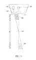
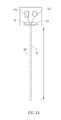
- An exemplary LiDAR systemincluded eight assemblies of eight lasers each as shown in FIG. 1 , or two assemblies of 32 lasers each forming a 64-element LiDAR system as shown in FIG. 2 . Yet other numbers of lasers or detectors are possible, and in general the LiDAR was employed in an assembly configured to rotate at a high rate of speed in order to capture a high number of reflected pulses in a full circle around the LiDAR sensor.
- the present inventionprovides a LiDAR-based 3-D point cloud measuring system.
- An example systemincludes a base, a housing, a plurality of photon transmitters and photon detectors contained within the housing, a rotary motor that rotates the housing about the base, and a communication component that allows transmission of signals generated by the photon detectors to external components.
- the systemprovides 32 emitter/detector pairs aligned along a vertical axis within a housing that spins to provide a 360 degree field of view.
- the emittersmay be aligned along a first axis, with the detectors aligned along a second axis adjacent to the first.
- the emitters and detectorsare mounted on thin circuit boards such as ceramic hybrid boards allowing for installation on a vertical motherboard for a vertical configuration, improved alignment, and other advantages.
- the motherboardin one version is formed with a hole in which the emitters fire rearward into a mirror, reflecting the emitted light through the hole and through lenses adjacent the motherboard.
- the systememploys a conjoint lens system that reduces or eliminates the parallax problem that may arise with the use of separate emitter and detector optics.
- the emittersfire in a non-adjacent pattern, and most preferably in a pattern in which sequentially fired lasers are physically distant from one another in order to reduce the likelihood of crosstalk.
- FIG. 1is a front view of a rotating LiDAR system.
- FIG. 2is a perspective view of an alternate LiDAR system.
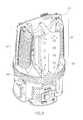
- FIG. 3is a perspective view of a preferred LiDAR system, showing an exemplary field of view of the laser emitters.
- FIG. 4is a side view of the preferred LiDAR system of FIG. 3 .
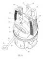
- FIG. 5is a side view of the LiDAR system in accordance with FIG. 4 , shown with the housing removed.
- FIG. 6is a perspective view of a hybrid containing a preferred detector.
- FIG. 7is a perspective view of a hybrid containing a preferred emitter.
- FIG. 8is a back perspective view of the LiDAR system as shown in FIG. 5 .
- FIG. 9is a top perspective view of the LiDAR system as shown in FIG. 5 .
- FIG. 10is an exemplary view of a LiDAR system with a potential parallax problem.
- FIG. 11is an exemplary front view of a lens assembly.
- FIG. 12is a sectional view of a lens assembly, taken along line A-A in FIG. 11 .
- FIG. 13is a sectional view of an alternate lens assembly, taken along line A-A in FIG. 11 .
- FIG. 14is a representative view of a conjoined D-shaped lens solving the parallax problem of FIG. 10 .
- FIG. 15is a front view of the LiDAR system as shown in FIG. 5 .
- FIG. 16is an exemplary view of a rotary coupler for coupling a housing to a rotating head assembly.
- FIG. 17is an illustration of a potential crosstalk problem.
- FIG. 18is an illustration of a further potential crosstalk problem.
- Exemplary LiDAR systemsare shown in FIGS. 1 and 2 .
- a rotating housingfires light pulses that reflect from objects so that the return reflections may be detected by detectors within the rotating housing.
- FOVhorizontal field of view
- the systemis typically mounted on the top center of a vehicle, giving it a clear view in all directions, and rotates at a rate of about 10 Hz (600 RPM), thereby providing a high point cloud refresh rate, such high rate being advantageous for autonomous navigation at higher speeds.
- the spin rateis within a range of about 5 to 20 Hz (300-1200 RPM).
- the systemcan collect approximately 2.56 million time of flight (TOF) distance points per second.
- TOFtime of flight
- the systemtherefore provides the unique combination of 360 degree FOV, high point cloud density, and high refresh rate.
- the standard deviation of TOF distance measurementsis equal to or less than 2 cm.
- the LiDAR systemmay incorporate an inertial navigation system (INS) sensor system mounted on it to report x, y, z deviations and pitch, roll, and yaw of the unit that is used by navigational computers to correct for these deviations.
- INSinertial navigation system
- a dynamic power featureallows the system to increase the intensity of the laser emitters if a clear terrain reflection is not obtained by photo detectors (whether due to reflective surface, weather, dust, distance, or other reasons), and to reduce power to the laser emitters for laser life and safety reasons if a strong reflection signal is detected by photo detectors.
- a direct benefit of this featureis that the LiDAR system is capable of seeing through fog, dust, and heavy rain by increasing laser power dynamically and ignoring early reflections.
- the unitalso has the capability to receive and decipher multiple returns from a single laser emission through digitization and analysis of the waveform generated by the detector as the signal generated from the emitter returns.
- the LiDAR systems of FIGS. 1 and 2report data in the form of range and intensity information via Ethernet (or similar output) to a master navigational system.
- the range datais converted into x and y coordinates and a height value.
- the height valuecan be corrected for the vehicle's pitch and roll so the resulting map is with reference to the horizontal plane of the vehicle.
- the mapis then “moved” in concert with the vehicle's forward or turning motion.
- the sensor's inputis cumulative and forms an ultra-high-density profile map of the surrounding environment.
- the LiDAR systemidentifies of size and distance of objects in view, including the vertical position and contour of a road surface.
- the anticipated offset of the vehicle from a straight, level path, either vertical or horizontal, at different distancesis translated into the G-force that the vehicle will be subject to when following the proposed path at the current speed. That information can be used to determine the maximum speed that the vehicle should be traveling, and acceleration or braking commands are issued accordingly.
- the softwareseeks the best available road surface (and thus the best possible speed) still within the boundaries of a global positioning system (GPS) waypoint being traversed.
- GPSglobal positioning system
- One version of the inventor's prior system as illustrated in FIG. 1includes 64 emitter/detector (i.e. laser diode/photo diode) pairs divided into eight groups of eight.
- the system shown in FIG. 2also includes 64 emitter/detector pairs, but in a configuration of 2 assemblies of 32 pairs. It is also possible to “share” a single detector among several lasers by focusing several detection regions onto a single detector, or by using a single, large detector. By firing a single laser at a time, there would be no ambiguity as to which laser is responsible for a return signal. Conversely, one could also sub-divide a single laser beam into several smaller beams. Each beam would be focused onto its own detector. In any event, such systems are still considered emitter-detector pairs.
- the laser diodeis preferably an OSRAM 905 nm emitter, and the photo diode is preferably an Avalanche variety. More particularly, in the preferred version each one of the detectors is an avalanche photodiode detector.
- the lensesare preferably UV treated to block sunlight, or employ a separate UV lens filter in the optical path. Each pair is preferably physically aligned in 1 ⁇ 3° increments, ranging from approximately 2° above horizontal to approximately 24° below horizontal.
- Each of the emitter/detector pairsare controlled by one or more DSPs (or, in some versions, field programmable gate arrays, or FPGAs, or other microprocessor), which determines when they will fire, determines the intensity of the firing based on the previous return, records the time-of-flight, calculates height data based time-of-flight and angular alignment of each pair. Results, including multiple returns if any, are transmitted via Ethernet to the master navigational computer via a rotary coupling.
- DSPsor, in some versions, field programmable gate arrays, or FPGAs, or other microprocessor
- the systememploys a control component that does not allow the emitters to fire until the head has reached a desired minimal rotation speed.
- ADCsAnalog to Digital Converters
- the detectorsare power cycled, such that only the desired detector is powered up at any one time. Then the signals can simply be multiplexed together.
- An additional benefit of power-cycling the detectorsis that total system power consumption is reduced, and the detectors therefore run cooler and are therefore more sensitive.
- a simple DC motor controller driving a high reliability brushed or brushless motorcontrols the rotation of the emitter/detectors.
- a rotary encoderfeeds rotational position to the DSPs (or other microprocessor) that use the position data to determine firing sequence.
- Software and physical fail-safesensure that no firing takes place until the system is rotating at a minimum RPM.
- FIG. 2illustrates a perspective view of a 64 emitter/detector pair LiDAR component 150 .
- the component 150includes a housing 152 that is opened on one side for receiving a first LiDAR system 154 located above a second LiDAR system 156 .
- the second LiDAR system 156is positioned to have line of sight with a greater angle relative to horizontal than the first LiDAR system 154 .
- the housing 152is mounted over a base housing section 158 .
- the LiDAR system of FIG. 2includes a magnetic rotor and stator.
- a rotary couplingsuch as a three-conductor Mercotac model 305 , passes through the center of the base 158 and the rotor.
- the three conductors facilitated by the rotary couplingare power, signal, and ground.
- a bearingmounts on the rotary coupling.
- a rotary encoderhas one part mounted on the rotary coupling and another part mounted on the base section 158 of the housing 152 .
- the rotary encodersuch as a U.S. Digital Model number E65-1000-750-I-PKG1 provides information regarding to rotary position of the housing 152 .
- the magnetic rotor and statorcause rotary motion of the base section 158 and thus the housing 152 about the rotary coupling.
- HDL-32EHigh Definition LiDAR 32E
- a pluralityin this embodiment up to 32
- laser emitter/detector pairsare aligned along a vertical axis with the entire head spinning to provide a 360 degrees horizontal field of view (FOV).
- Each laserissues light pulses (in this version, 5 ns pulses) that are analyzed for time-of-flight distance information (called a “distance pixel” or “return”).
- the system reportsreturns in Ethernet packets, providing both distance and intensity (i.e.
- the cylindrical sensor head 10is about 3.5 inches in diameter and the unit has an overall height of 5.6 inches and weighs about 2.4 pounds.
- the HDL-64Eshown in FIG. 2
- the HDL-64Eis 8 inches in diameter by approximately one foot tall, and weighs about 29 pounds. This reduction in size is the result of several inventive improvements, as described more fully below.
- the sample embodiment of FIG. 3can be built with a variable number of lasers, aligned over a vertical FOV 12 of +10 to ⁇ 30 degrees as best seen in FIG. 4 .
- the vertical FOVmay be made larger or smaller, as desired, by adjusting the number or orientation of the emitters and detectors. When using the emitters as described and orienting them as described, the range is approximately 100 meters.
- the head 10is mounted on a fixed platform 14 having a motor configured such that it preferably spins at a rate of 5 Hz to 20 Hz (300-1200 RPM).
- the sample systemuses 905 nm laser diodes (although other frequencies such as 1550 nm could be used) and is Class 1 eye safe.
- FIG. 5illustrates the same version as shown in FIGS. 3 and 4 , though without the outer housing covering the internal components.
- the systemincludes a main motherboard 20 supporting a plurality of detector hybrids 32 and emitter hybrids (not visible in FIG. 5 ).
- the emittersfire back toward the rear of the system, where the pulses are reflected from a mirror and then are directed through a lens 50 . Return pulses pass through a lens, are reflected by a mirror 40 , then directed to the detectors incorporated into the hybrids 32 .
- the motherboard 20 and mirror 40are mounted to a common frame 22 providing common support and facilitating alignment.
- the hybrids 32are mounted to the motherboard in a fan pattern that is organized about a central axis.
- 32 hybridsare used in a pattern to create a field of view extending 10 degrees above and 30 degrees below the horizon and therefore the central axis extends above and below the ninth board 38 , with 8 boards above and 23 boards below the central axis.
- each successive boardis inclined an additional one and one-third degree with respect to the next adjacent board. The desired incremental and overall inclination may be varied depending on the number of hybrids used, the geometry of the mirrors and lenses, and the desired range of the system.
- the thin circuit boardsare in the form of ceramic hybrid boards that are about 0.015 inches thick, with only one emitter mounted on each emitter board, and only one detector mounted on each detector board.
- the thin circuit boardsmay be formed from other materials or structures instead of being configured as ceramic hybrids.
- the detectorsare positioned in a first vertical alignment along a first vertical axis while the emitters are positioned in a second vertical alignment along a second vertical axis, with the first and second vertical axes being parallel and next to one another.
- the hybrid boards carrying the emitters and detectorsare mounted in vertical stacks that allow the sensor head to have a smaller diameter than a differently configured sensor having emitters and detectors positioned about the circumference of the system. Accordingly, the configuration reduces the overall size and requires less energy for spinning by moving more of the weight toward the center of the sensor.
- the preferred versionincorporates a plurality of detectors (in this case, 32 of them) mounted to an equal number of detector hybrids 32 .
- the systemlikewise has the same number of emitters mounted to an equal number of emitter hybrids 30 .
- the systemtherefore has one emitter per hybrid and one detector per hybrid. In other versions this may be varied, for example to incorporate multiple emitters or detectors on a single hybrid.
- the emitter and detector hybridsare connected to a common motherboard 20 , which is supported by a frame 22 .
- the motherboardhas a central opening 24 that is positioned to allow emitted and received pulses to pass through the motherboard. Because the lenses are positioned over the middle of the motherboard, the central opening is configured to be adjacent the lenses to allow light to pass through the portion of the motherboard that is next to the lenses.
- the density of emitter/detector pairs populated along the vertical FOVis intentionally variable. While 32 pairs of emitters and detectors are shown in the illustrated versions, the use of hybrids and a motherboard allows for a reduction in the number of emitters and detectors by simply removing or not installing any desired number of emitter/detector pairs. This variation of the invention cuts down on the number vertical lines the sensor produces, and thus reduce cost. It is feasible that just a few emitter/detector pairs will accomplish the goals of certain autonomous vehicles or mapping applications. For some uses increased density is desirable to facilitate seeing objects at further distances and with more vertical resolution. Other uses exploit the fact that there is a direct relationship between the number of emitter detector pairs and sensor cost, and do not need the full spread of vertical lasers to accomplish their sensor goals.
- multiple emitters and detectorscan be designed and mounted onto the hybrid boards at slightly different vertical angles, thus increasing the density of vertical FOV coverage in the same footprint. If, for example, two emitters and two detectors were mounted on each of the hybrids shown in FIGS. 6 and 7 with slight vertical offsets, the design would incorporate 64 emitters and detectors rather than 32. This example design describes two emitters and detectors mounted per board, but there is no practical limit to the number of emitters and detectors that may be mounted on a single board. The increased number of emitters and detectors may be used to increase the field of view by adjusting the relative orientation, or may be used to increase the density of points obtained within the same field of view.
- the vertical motherboardon which the main electronics that control the firing of the lasers and the capturing of returns are located.
- the motherboardis mounted vertically, defining a plane that is preferably parallel to the central axis 13 (see FIG. 3 ) about which the system will rotate. While the motherboard is preferably parallel to this axis of rotation, it may be inclined toward a horizontal plane by as much as 30 degrees and still be considered substantially vertical in orientation.
- the emitter and detector hybrid boardsare aligned and soldered directly to this vertical motherboard, thus providing for small overall head size and increased reliability due to the omission of connectors that connect the laser boards with the motherboard.
- This boardis mechanically self-supported, mounted to a frame 22 that fixes it rigidly in position in a vertical orientation so that it spins with the rotating sensor head.
- the insertion of the hybrid boardscan be automated for easy assembly.
- Prior art sensorsexclusively employ motherboard design requiring connectors and cables between the emitters and detectors and the motherboard. The positioning and configuration of the motherboard as shown overcomes these problems.
- the motherboardis positioned between the mirror and the lenses, as best seen in FIG. 9 .
- the sensor headincludes one or more lenses 50 , 52 supported within a lens frame 54 positioned at a front side of the sensor head.
- One or more mirrors 40 , 42are positioned at the opposite side of the sensor head and mounted to the frame 22 .
- the frame 22is a unitary frame formed from a single piece of material that supports the motherboard and the mirrors.
- This configurationallows the hybrid emitters to fire rearward into the first mirror 40 , wherein the light then reflects off the mirror and travels through the hole 24 in the motherboard 20 , through the lens 50 and so that the emitted light 60 travels out to the target 70 .
- This configurationfurther increases the net focal length of the light path while retaining small size.
- the returning light 62passes through the detector lens 52 , through the hole 24 in the motherboard to the opposite mirror 52 and is reflected into the corresponding detector.
- the various componentsare positioned to allow a near-balanced condition upon initial assembly that requires a minimum of final static and dynamic balancing counterweights.
- this balancingis obtained by positioning major portions of components about the circumference of the sensor head. More specifically, the lenses and frame are on one side while the mirrors and a generally T-shaped portion of the frame is diametrically opposite the lenses, with the mirrors and rearward portion of the frame configured to have a weight that is about equal to that of the lenses and lens frame.
- the emitter and detector hybridsare carried on diametrically opposite sides of the sensor head, positioned at about a 90 degree offset with respect to the lens and mirror diameter.
- the motherboardis nearly along a diameter, positioned to counter balance the weight of the other components, such that the center of gravity is at the center of rotation defined by the center of the base 80 .
- GPS and inertial sensorsare often included to locate the vehicle in space and correct for normal vehicle motion.
- Inertial sensorsoften include gyros, such as fiber optic gyros (FOG), and accelerometers.
- gyrossuch as fiber optic gyros (FOG)
- accelerometersthere is a 6-axis inertial sensor system mounted in the LiDAR base and the signals from the gyros and accelerometers are output along with the LiDAR distance and intensity data.
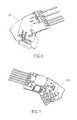
- a representative emitter 170transmits a light signal through a lens 172 , with the propagated light signal traveling outward and toward a target in the distance. Light reflected from a target may return through a second lens 162 and onward toward a detector 160 .
- the nonparallel orientation of the emitter and detectorcreates nonparallel light emitter and detector paths. Consequently, there is a near blind spot 180 adjacent the system and a far blind spot 184 more distant from the system. In either of the two blind spots, light reflecting from an object will return along a path that cannot be received by the detector. The near blind spot extends for a distance “A” in front of the system, while the far blind spot extends in the region of distance “C” beyond the system. Between the two blind spots, in a distance defined by “B”, the system will see an object in that light reflected from the object can return along a path that can be detected.
- region Bthere is a “sweet spot” 182 defined by the straight line paths of travel from the emitter and to the detector.
- the “sweet spot” 182 for parallax alignmentis approximately 100 feet from the centerline of the sensor. Inside of about 10 feet the emitter's light misses its corresponding detector entirely, shown at 180 , and beyond approximately 240 feet, shown at 184 , the signal becomes weak due to the misalignment of the emitter and detector in the opposite direction.
- This effectcan be alleviated in one version of the invention by having two “D”-shaped lenses 50 , 52 (see FIG. 15 ), constructed for the emitter and detector, and having these two lenses attached to each other with a minimal gap in between.
- the close proximity of the conjoint lens systemreduces the “blind” region to near zero, as shown by the parallel nature of the emitter's light 60 and detector's light path 62 .
- a lens arrayDue to the complex nature of the optical propagation in lenses, a lens array is usually needed to correct for various aberrations that are commonly associated with any optical design. For the purpose of constructing a conjoint lens system to overcome the parallax problem described with respect to FIG. 10 , it is useful to have the first surface of the lens array being the largest pupil; that is, the optical rays entering the lens system should bend towards the center.
- FIG. 11illustrates a front view of a lens array 50 .
- the emitter lens arrayit may also be illustrative of the detector lens array as well.
- an edge 51 of the otherwise circular lensis cut away from the lens, removing a left edge 120 of the otherwise circular lens.
- the resulting lensis somewhat D-shaped, having a vertical left edge.
- the use of a D-shaped lens arrayis advantageous in that D-shaped lens arrays for the emitter and detector may be placed back-to-back to form “conjoined” D-shape lens arrays as best seen in FIG. 15 . Placing the vertical edges of the D-shapes adjacent one another allows the otherwise circular lenses to be much closer to one another than would be the case if using circular lenses which would only allow for tangential contact between the lens arrays.
- FIG. 12illustrates a correct design of the lens array, shown in sectional view taken along lines A-A from FIG. 11 .
- the lens arrayincludes a first lens 113 , a second lens 111 , and a third lens 112 .
- the input rays 100always bend towards the center in this lens array. Consequently, when a D-shaped cut is made (that is, cutting off a portion of one side of each of the lenses in the area indicated by the shaded region 120 ), there is no loss of light. As the shaded region indicates, all of the light entering the first lens 113 travels through the entire lens array to the mirror.
- FIG. 13illustrates an incorrect design having a similar array of three lenses 110 , 111 , 112 .
- the front lens 110is differently shaped and some of the input light rays 100 bend away from the center as they travel through the front lens. A cut through the ends of one side of this lens array would result in the loss of some of the light entering the array, as indicated in the shaded region 120 in FIG. 12 .
- each side of the lens arraymay be cut in the form of a D-shape. This creates a straight edge along the sides of each lens in the array, allowing the straight sides of the D's forming each lens array to be positioned closely adjacent one another.
- the term “closely adjacent”is understood to mean either in contact with one another or positioned such that the center of the lenses are closer to one another than they could be without the D-shaped cut.
- the two lens arrays 50 , 52are positioned closely adjacent one another with the straight sides back-to-back to form conjoined D-shaped lens arrays.
- a first lens array 50serves as the emitter lens array while the adjacent second lens array 52 serves as the detector lens array.
- FIG. 14illustrates an advantage of the conjoint D-shaped lens design, particularly in how it overcomes the parallax problem illustrated in FIG. 10 .
- light emerging from the emitter 170is directed to a first D-shaped lens 50 .
- the emitteris oriented to direct its light path toward a position just inward of the straight side edge of the D-shape. Because of the lens array configuration of the type described in FIG. 12 , the light emerges from the first lens 50 in a straight line 60 that can be directed radially away from the sensor head. Likewise, light reflected from the distant object will return along a return path 62 that is parallel to the emitter light path.
- the closely parallel return pathwill travel through the second, adjacent conjoined D lens array 52 , entering the lens array at a position just inward of the straight side edge of the D-shape, where it is then directed to the detector 160 . Consequently, there is no blind spot as with conventional lenses and the parallax problem is resolved.
- Another unique design consideration for the preferred implementationaddresses the need to transfer power and signal up to the head, and receive signal and offer grounding down from the head.
- Off the shelf mercury-based rotary couplersare too unreliable and too big for this problem.
- the use of a rotary transformer 145enables sending power up to the head, and the use of a capacitive coupler 140 down from the head to accommodate these requirements.
- a phase modulation schemeallows for communication to the head from the base using serial commands in order to instruct the head to limit horizontal field of view, fire all lasers at full power, update its firmware, and other commands.
- the distance returns of the LiDAR scannerbe as accurate as possible and be free of spurious images or returns. Firing multiple lasers at once can create a crosstalk condition where the light emitted from one laser inadvertently is detected by the detector of another laser, thus giving a false return.
- emitters E 1 through E 4all fire at once, their returns would be intended to be received by emitters D 1 through D 4 .
- light from one of the emittersmay be directed to the wrong detector. For example, as indicated in FIG. 17 , light from emitter E 1 may end up directed to detector D 3 , as indicated by the dotted line return path. This would be an invalid return, and the system would erroneously associate it with light sent from emitter E 3 , thereby creating a faulty pixel in the point cloud.
- a similar errorcan occur if adjacent lasers are fired in a sequential fashion.
- firing a single emitter E 1may result in light being detected at detector D 2 rather than D 1 . This may most commonly occur when light from emitter E 1 travels beyond the true range of the sensor but is reflected from a particularly reflective object, such as a stop sign covered with reflective paint. The firing of adjacent emitters in order makes this form of cross-talk more likely.
- the emittersare fired in a non-adjacent single laser firing order. This means that only one emitter detector pair is active at any given time, and at no time do adjacent emitters and detectors fire in sequence. Most preferably there is as much distance as possible between the emitters that are fired in order. Thus, if there are 32 emitters in a vertical stack, the emitters would be assigned labels E 1 representing the top-most emitter and then sequentially numbered through E 32 representing the bottom emitter in the stack.
- Emitter E 1(at the top) would be fired first, followed by emitter E 17 (in the middle of the stack), then E 2 , E 18 , E 3 , E 19 , and so on, ending with E 16 and E 32 before starting over again at the beginning
- This patternbegins with the top emitter and the middle emitter, dividing the stack into two groups. It then alternates firing one from each group, moving from the top of each half-stack and proceeding sequentially down each half-stack of emitters in an this alternating fashion and then repeating. This pattern ensures the largest possible distance between fired lasers, thereby reducing the chance of crosstalk.
Landscapes
- Engineering & Computer Science (AREA)
- Physics & Mathematics (AREA)
- Computer Networks & Wireless Communication (AREA)
- General Physics & Mathematics (AREA)
- Radar, Positioning & Navigation (AREA)
- Remote Sensing (AREA)
- Electromagnetism (AREA)
- Optical Radar Systems And Details Thereof (AREA)
Abstract
Description
Claims (18)
Priority Applications (9)
| Application Number | Priority Date | Filing Date | Title |
|---|---|---|---|
| US13/109,901US8767190B2 (en) | 2006-07-13 | 2011-05-17 | High definition LiDAR system |
| US15/180,580USRE46672E1 (en) | 2006-07-13 | 2016-06-13 | High definition LiDAR system |
| US15/700,844USRE48490E1 (en) | 2006-07-13 | 2017-09-11 | High definition LiDAR system |
| US15/700,571USRE48503E1 (en) | 2006-07-13 | 2017-09-11 | High definition LiDAR system |
| US15/700,543USRE47942E1 (en) | 2006-07-13 | 2017-09-11 | High definition lidar system |
| US15/700,836USRE48504E1 (en) | 2006-07-13 | 2017-09-11 | High definition LiDAR system |
| US15/700,959USRE48688E1 (en) | 2006-07-13 | 2017-09-11 | High definition LiDAR system |
| US15/700,965USRE48491E1 (en) | 2006-07-13 | 2017-09-11 | High definition lidar system |
| US15/700,558USRE48666E1 (en) | 2006-07-13 | 2017-09-11 | High definition LiDAR system |
Applications Claiming Priority (4)
| Application Number | Priority Date | Filing Date | Title |
|---|---|---|---|
| US80730506P | 2006-07-13 | 2006-07-13 | |
| US11/777,802US7969558B2 (en) | 2006-07-13 | 2007-07-13 | High definition lidar system |
| US34550510P | 2010-05-17 | 2010-05-17 | |
| US13/109,901US8767190B2 (en) | 2006-07-13 | 2011-05-17 | High definition LiDAR system |
Related Parent Applications (2)
| Application Number | Title | Priority Date | Filing Date |
|---|---|---|---|
| US11/777,802Continuation-In-PartUS7969558B2 (en) | 2006-07-13 | 2007-07-13 | High definition lidar system |
| US15/180,580ContinuationUSRE46672E1 (en) | 2006-07-13 | 2016-06-13 | High definition LiDAR system |
Related Child Applications (8)
| Application Number | Title | Priority Date | Filing Date |
|---|---|---|---|
| US15/180,580ReissueUSRE46672E1 (en) | 2006-07-13 | 2016-06-13 | High definition LiDAR system |
| US15/700,571ReissueUSRE48503E1 (en) | 2006-07-13 | 2017-09-11 | High definition LiDAR system |
| US15/700,959ReissueUSRE48688E1 (en) | 2006-07-13 | 2017-09-11 | High definition LiDAR system |
| US15/700,965ReissueUSRE48491E1 (en) | 2006-07-13 | 2017-09-11 | High definition lidar system |
| US15/700,844ReissueUSRE48490E1 (en) | 2006-07-13 | 2017-09-11 | High definition LiDAR system |
| US15/700,558ReissueUSRE48666E1 (en) | 2006-07-13 | 2017-09-11 | High definition LiDAR system |
| US15/700,836ReissueUSRE48504E1 (en) | 2006-07-13 | 2017-09-11 | High definition LiDAR system |
| US15/700,543ReissueUSRE47942E1 (en) | 2006-07-13 | 2017-09-11 | High definition lidar system |
Publications (2)
| Publication Number | Publication Date |
|---|---|
| US20110216304A1 US20110216304A1 (en) | 2011-09-08 |
| US8767190B2true US8767190B2 (en) | 2014-07-01 |
Family
ID=44262880
Family Applications (1)
| Application Number | Title | Priority Date | Filing Date |
|---|---|---|---|
| US13/109,901CeasedUS8767190B2 (en) | 2006-07-13 | 2011-05-17 | High definition LiDAR system |
Country Status (3)
| Country | Link |
|---|---|
| US (1) | US8767190B2 (en) |
| EP (4) | EP3786668A1 (en) |
| WO (1) | WO2011146523A2 (en) |
Cited By (223)
| Publication number | Priority date | Publication date | Assignee | Title |
|---|---|---|---|---|
| US9360554B2 (en) | 2014-04-11 | 2016-06-07 | Facet Technology Corp. | Methods and apparatus for object detection and identification in a multiple detector lidar array |
| US9510505B2 (en)* | 2014-10-10 | 2016-12-06 | Irobot Corporation | Autonomous robot localization |
| US9671094B2 (en) | 2010-07-22 | 2017-06-06 | Renishaw Plc | Laser scanning apparatus and method of use |
| US9720415B2 (en) | 2015-11-04 | 2017-08-01 | Zoox, Inc. | Sensor-based object-detection optimization for autonomous vehicles |
| US9804264B2 (en) | 2015-11-30 | 2017-10-31 | Luminar Technologies, Inc. | Lidar system with distributed laser and multiple sensor heads |
| US9810786B1 (en) | 2017-03-16 | 2017-11-07 | Luminar Technologies, Inc. | Optical parametric oscillator for lidar system |
| US9810775B1 (en) | 2017-03-16 | 2017-11-07 | Luminar Technologies, Inc. | Q-switched laser for LIDAR system |
| US9841495B2 (en) | 2015-11-05 | 2017-12-12 | Luminar Technologies, Inc. | Lidar system with improved scanning speed for high-resolution depth mapping |
| US9866816B2 (en) | 2016-03-03 | 2018-01-09 | 4D Intellectual Properties, Llc | Methods and apparatus for an active pulsed 4D camera for image acquisition and analysis |
| US9869754B1 (en) | 2017-03-22 | 2018-01-16 | Luminar Technologies, Inc. | Scan patterns for lidar systems |
| US9896091B1 (en) | 2016-08-19 | 2018-02-20 | Ohio State Innovation Foundation | Optimized path planner for an autonomous valet parking system for a motor vehicle |
| US9904081B2 (en) | 2016-06-20 | 2018-02-27 | Raytheon Company | LCWG steered laser transmitter and situational awareness sensor with wavelength conversion |
| US9905992B1 (en) | 2017-03-16 | 2018-02-27 | Luminar Technologies, Inc. | Self-Raman laser for lidar system |
| US20180081361A1 (en)* | 2016-09-20 | 2018-03-22 | Waymo Llc | Devices and Methods for a Sensor Platform of a Vehicle |
| US9927515B2 (en) | 2015-06-24 | 2018-03-27 | Raytheon Company | Liquid crystal waveguide steered active situational awareness sensor |
| US9983297B2 (en) | 2016-03-21 | 2018-05-29 | Veloyne Lidar, Inc. | LIDAR based 3-D imaging with varying illumination field density |
| US9992477B2 (en) | 2015-09-24 | 2018-06-05 | Ouster, Inc. | Optical system for collecting distance information within a field |
| US9989629B1 (en) | 2017-03-30 | 2018-06-05 | Luminar Technologies, Inc. | Cross-talk mitigation using wavelength switching |
| US10003168B1 (en) | 2017-10-18 | 2018-06-19 | Luminar Technologies, Inc. | Fiber laser with free-space components |
| US10007001B1 (en) | 2017-03-28 | 2018-06-26 | Luminar Technologies, Inc. | Active short-wave infrared four-dimensional camera |
| US10012986B2 (en) | 2016-08-19 | 2018-07-03 | Dura Operating, Llc | Method for autonomously parking a motor vehicle for head-in, tail-in, and parallel parking spots |
| US10018726B2 (en) | 2016-03-19 | 2018-07-10 | Velodyne Lidar, Inc. | Integrated illumination and detection for LIDAR based 3-D imaging |
| US10024970B2 (en) | 2016-08-19 | 2018-07-17 | Dura Operating, Llc | Sensor housing assembly for attachment to a motor vehicle |
| US10036801B2 (en) | 2015-03-05 | 2018-07-31 | Big Sky Financial Corporation | Methods and apparatus for increased precision and improved range in a multiple detector LiDAR array |
| US10048374B2 (en) | 2016-03-21 | 2018-08-14 | Velodyne Lidar, Inc. | LIDAR based 3-D imaging with varying pulse repetition |
| US10048358B2 (en) | 2016-12-30 | 2018-08-14 | Panosense Inc. | Laser power calibration and correction |
| US10063849B2 (en) | 2015-09-24 | 2018-08-28 | Ouster, Inc. | Optical system for collecting distance information within a field |
| US10063756B2 (en)* | 2016-06-07 | 2018-08-28 | Lg Electronics Inc. | Camera module and mobile terminal having the same |
| US10061019B1 (en) | 2017-03-28 | 2018-08-28 | Luminar Technologies, Inc. | Diffractive optical element in a lidar system to correct for backscan |
| EP3370209A1 (en) | 2017-03-02 | 2018-09-05 | Topcon Corporation | Point cloud data processing device, point cloud data processing method, and point cloud data processing program |
| WO2018160729A2 (en) | 2017-03-01 | 2018-09-07 | Pointcloud, Inc. | Modular three-dimensional optical sensing system |
| WO2018175387A1 (en)* | 2017-03-20 | 2018-09-27 | Velodyne Lidar, Inc. | Lidar based 3-d imaging with structured light and integrated illumination and detection |
| US10088559B1 (en) | 2017-03-29 | 2018-10-02 | Luminar Technologies, Inc. | Controlling pulse timing to compensate for motor dynamics |
| US10094925B1 (en) | 2017-03-31 | 2018-10-09 | Luminar Technologies, Inc. | Multispectral lidar system |
| US10109183B1 (en) | 2016-12-30 | 2018-10-23 | Panosense Inc. | Interface for transferring data between a non-rotating body and a rotating body |
| US10114111B2 (en) | 2017-03-28 | 2018-10-30 | Luminar Technologies, Inc. | Method for dynamically controlling laser power |
| US10121813B2 (en) | 2017-03-28 | 2018-11-06 | Luminar Technologies, Inc. | Optical detector having a bandpass filter in a lidar system |
| US10122416B2 (en) | 2016-12-30 | 2018-11-06 | Panosense Inc. | Interface for transferring power and data between a non-rotating body and a rotating body |
| US10141716B1 (en) | 2013-09-30 | 2018-11-27 | Waymo Llc | Laser diode firing system |
| US10139478B2 (en) | 2017-03-28 | 2018-11-27 | Luminar Technologies, Inc. | Time varying gain in an optical detector operating in a lidar system |
| US10148056B2 (en) | 2016-06-20 | 2018-12-04 | Raytheon Company | Ring amplifier for extended range steerable laser transmitter and active sensor |
| US10175361B2 (en) | 2016-07-28 | 2019-01-08 | Sharp Laboratories Of America, Inc. | System and method for three-dimensional mapping using two-dimensional LiDAR laser ranging |
| US10191155B2 (en) | 2017-03-29 | 2019-01-29 | Luminar Technologies, Inc. | Optical resolution in front of a vehicle |
| US10197669B2 (en) | 2016-03-21 | 2019-02-05 | Velodyne Lidar, Inc. | LIDAR based 3-D imaging with varying illumination intensity |
| US10203399B2 (en) | 2013-11-12 | 2019-02-12 | Big Sky Financial Corporation | Methods and apparatus for array based LiDAR systems with reduced interference |
| US10207704B2 (en) | 2016-08-19 | 2019-02-19 | Dura Operating, Llc | Method for autonomously parking and un-parking a motor vehicle |
| US10209359B2 (en) | 2017-03-28 | 2019-02-19 | Luminar Technologies, Inc. | Adaptive pulse rate in a lidar system |
| US10222475B2 (en) | 2017-05-15 | 2019-03-05 | Ouster, Inc. | Optical imaging transmitter with brightness enhancement |
| US10222458B2 (en) | 2016-08-24 | 2019-03-05 | Ouster, Inc. | Optical system for collecting distance information within a field |
| US10241198B2 (en) | 2017-03-30 | 2019-03-26 | Luminar Technologies, Inc. | Lidar receiver calibration |
| US10254388B2 (en) | 2017-03-28 | 2019-04-09 | Luminar Technologies, Inc. | Dynamically varying laser output in a vehicle in view of weather conditions |
| US10254762B2 (en) | 2017-03-29 | 2019-04-09 | Luminar Technologies, Inc. | Compensating for the vibration of the vehicle |
| EP3467436A1 (en) | 2017-10-03 | 2019-04-10 | Topcon Corporation | Unmanned aerial vehicle, data processing device, path selection device, processing method and processing program |
| US10267899B2 (en) | 2017-03-28 | 2019-04-23 | Luminar Technologies, Inc. | Pulse timing based on angle of view |
| EP3474109A1 (en) | 2017-10-17 | 2019-04-24 | Topcon Corporation | Measuring device, control device for unmanned aerial vehicle and method for controlling unmanned aerial vehicle |
| DE202018100458U1 (en) | 2018-01-26 | 2019-04-29 | Sick Ag | Opto-electronic sensor for detecting objects |
| EP3483554A1 (en) | 2017-11-13 | 2019-05-15 | Topcon Corporation | Surveying device, and calibration checking method and calibration checking program for surveying device |
| US10295668B2 (en) | 2017-03-30 | 2019-05-21 | Luminar Technologies, Inc. | Reducing the number of false detections in a lidar system |
| US10295660B1 (en) | 2016-12-30 | 2019-05-21 | Panosense Inc. | Aligning optical components in LIDAR systems |
| USD849573S1 (en)* | 2017-08-23 | 2019-05-28 | Uber Technologies, Inc. | Lidar sensor |
| US10310058B1 (en) | 2017-11-22 | 2019-06-04 | Luminar Technologies, Inc. | Concurrent scan of multiple pixels in a lidar system equipped with a polygon mirror |
| EP3495769A1 (en) | 2017-12-05 | 2019-06-12 | Topcon Corporation | Surveying device, and calibration method and calibration program for surveying device |
| DE102017222614A1 (en) | 2017-12-13 | 2019-06-13 | Robert Bosch Gmbh | Device for environmental detection and method for its operation |
| US20190178991A1 (en)* | 2017-12-08 | 2019-06-13 | Velodyne Lidar, Inc. | Systems and methods for improving detection of a return signal in a light ranging and detection system |
| US20190179018A1 (en)* | 2017-12-07 | 2019-06-13 | Velodyne Lidar, Inc. | Systems and methods for efficient multi-return light detectors |
| US10324184B1 (en) | 2018-07-03 | 2019-06-18 | Dolphin Co., Ltd. | Object detecting apparatus, object detecting method, and design method of object detecting apparatus |
| US10324170B1 (en) | 2018-04-05 | 2019-06-18 | Luminar Technologies, Inc. | Multi-beam lidar system with polygon mirror |
| US10340651B1 (en) | 2018-08-21 | 2019-07-02 | Luminar Technologies, Inc. | Lidar system with optical trigger |
| US10338594B2 (en) | 2017-03-13 | 2019-07-02 | Nio Usa, Inc. | Navigation of autonomous vehicles to enhance safety under one or more fault conditions |
| US10338586B2 (en) | 2016-08-19 | 2019-07-02 | Dura Operating, Llc | Method for controlling autonomous valet system pathing for a motor vehicle |
| EP3506042A1 (en) | 2017-12-27 | 2019-07-03 | Topcon Corporation | Three-dimensional information processing unit, apparatus having three-dimensional information processing unit, unmanned aerial vehicle, informing device, method and program for controlling mobile body using three-dimensional information processing unit |
| US10348051B1 (en) | 2018-05-18 | 2019-07-09 | Luminar Technologies, Inc. | Fiber-optic amplifier |
| US10359507B2 (en) | 2016-12-30 | 2019-07-23 | Panosense Inc. | Lidar sensor assembly calibration based on reference surface |
| EP3514489A1 (en) | 2018-01-23 | 2019-07-24 | Topcon Corporation | Surveying device and surveying method |
| DE102018101847A1 (en) | 2018-01-26 | 2019-08-01 | Sick Ag | Optoelectronic sensor and method for detecting objects |
| US10369974B2 (en) | 2017-07-14 | 2019-08-06 | Nio Usa, Inc. | Control and coordination of driverless fuel replenishment for autonomous vehicles |
| DE102018102601A1 (en) | 2018-02-06 | 2019-08-08 | Sick Ag | Optoelectronic sensor and method for detecting objects in a surveillance area |
| US10386230B1 (en) | 2012-12-31 | 2019-08-20 | Omni Medsci, Inc. | Near-infrared time-of-flight remote sensing |
| US10386465B2 (en) | 2017-03-31 | 2019-08-20 | Velodyne Lidar, Inc. | Integrated LIDAR illumination power control |
| US10393877B2 (en) | 2016-06-01 | 2019-08-27 | Velodyne Lidar, Inc. | Multiple pixel scanning LIDAR |
| US10401481B2 (en) | 2017-03-30 | 2019-09-03 | Luminar Technologies, Inc. | Non-uniform beam power distribution for a laser operating in a vehicle |
| DE202018103258U1 (en) | 2018-06-11 | 2019-09-12 | Sick Ag | Optical sensor for detecting objects |
| US10423162B2 (en) | 2017-05-08 | 2019-09-24 | Nio Usa, Inc. | Autonomous vehicle logic to identify permissioned parking relative to multiple classes of restricted parking |
| US10429495B1 (en)* | 2018-04-03 | 2019-10-01 | Hesai Photonics Technology Co., Ltd. | Lidar system and method |
| US10444359B2 (en) | 2017-07-05 | 2019-10-15 | Ouster, Inc. | Light ranging device with electronically scanned emitter array and synchronized sensor array |
| US10451716B2 (en) | 2017-11-22 | 2019-10-22 | Luminar Technologies, Inc. | Monitoring rotation of a mirror in a lidar system |
| US10473766B2 (en) | 2017-03-13 | 2019-11-12 | The Charles Stark Draper Laboratory, Inc. | Light detection and ranging (LiDAR) system and method |
| US10473767B2 (en) | 2017-06-19 | 2019-11-12 | Hesai Photonics Technology Co., Ltd. | Lidar system and method |
| US10481269B2 (en) | 2017-12-07 | 2019-11-19 | Ouster, Inc. | Rotating compact light ranging system |
| DE102018113849A1 (en) | 2018-06-11 | 2019-12-12 | Sick Ag | Optoelectronic sensor and method for detecting objects |
| EP3584603A1 (en) | 2018-06-19 | 2019-12-25 | Topcon Corporation | Reflection object position calculating device, reflection object position calculating method, and reflection object position calculating program |
| US10517484B2 (en) | 2012-12-31 | 2019-12-31 | Omni Medsci, Inc. | Semiconductor diodes-based physiological measurement device with improved signal-to-noise ratio |
| EP3591336A1 (en) | 2018-07-06 | 2020-01-08 | Topcon Corporation | Method, device, and program for surveying |
| US10539661B2 (en) | 2015-11-25 | 2020-01-21 | Velodyne Lidar, Inc. | Three dimensional LIDAR system with targeted field of view |
| US10545222B2 (en) | 2017-05-08 | 2020-01-28 | Velodyne Lidar, Inc. | LIDAR data acquisition and control |
| US10545240B2 (en) | 2017-03-28 | 2020-01-28 | Luminar Technologies, Inc. | LIDAR transmitter and detector system using pulse encoding to reduce range ambiguity |
| US10551501B1 (en) | 2018-08-09 | 2020-02-04 | Luminar Technologies, Inc. | Dual-mode lidar system |
| US10556585B1 (en) | 2017-04-13 | 2020-02-11 | Panosense Inc. | Surface normal determination for LIDAR range samples by detecting probe pulse stretching |
| US10557939B2 (en) | 2015-10-19 | 2020-02-11 | Luminar Technologies, Inc. | Lidar system with improved signal-to-noise ratio in the presence of solar background noise |
| US10571574B1 (en) | 2016-02-15 | 2020-02-25 | Red Creamery, LLC | Hybrid LADAR with co-planar scanning and imaging field-of-view |
| WO2020041573A1 (en) | 2018-08-22 | 2020-02-27 | Seeters Josephus M Van | Detection systems, communications systems and induction motors |
| US10591601B2 (en) | 2018-07-10 | 2020-03-17 | Luminar Technologies, Inc. | Camera-gated lidar system |
| US10591740B2 (en) | 2016-12-30 | 2020-03-17 | Panosense Inc. | Lens assembly for a LIDAR system |
| US10627516B2 (en) | 2018-07-19 | 2020-04-21 | Luminar Technologies, Inc. | Adjustable pulse characteristics for ground detection in lidar systems |
| US10627490B2 (en) | 2016-01-31 | 2020-04-21 | Velodyne Lidar, Inc. | Multiple pulse, LIDAR based 3-D imaging |
| US10634772B2 (en) | 2017-11-27 | 2020-04-28 | Atieva, Inc. | Flash lidar with adaptive illumination |
| US10641874B2 (en) | 2017-03-29 | 2020-05-05 | Luminar Technologies, Inc. | Sizing the field of view of a detector to improve operation of a lidar system |
| US10660526B2 (en) | 2012-12-31 | 2020-05-26 | Omni Medsci, Inc. | Near-infrared time-of-flight imaging using laser diodes with Bragg reflectors |
| US10663595B2 (en) | 2017-03-29 | 2020-05-26 | Luminar Technologies, Inc. | Synchronized multiple sensor head system for a vehicle |
| US10677897B2 (en) | 2017-04-14 | 2020-06-09 | Luminar Technologies, Inc. | Combining lidar and camera data |
| USRE48042E1 (en) | 2013-08-20 | 2020-06-09 | Waymo Llc | Devices and methods for a LIDAR platform with a shared transmit/receive path |
| US10684360B2 (en) | 2017-03-30 | 2020-06-16 | Luminar Technologies, Inc. | Protecting detector in a lidar system using off-axis illumination |
| US10684358B2 (en) | 2016-11-11 | 2020-06-16 | Raytheon Company | Situational awareness sensor using a fixed configuration of optical phased arrays (OPAs) |
| DE112018002081T5 (en) | 2017-04-19 | 2020-07-02 | Beijing Surestar Technology Co., Ltd | Laser scanning device, laser radar set and scanning method of the laser radar set |
| US10712434B2 (en) | 2018-09-18 | 2020-07-14 | Velodyne Lidar, Inc. | Multi-channel LIDAR illumination driver |
| US10710633B2 (en) | 2017-07-14 | 2020-07-14 | Nio Usa, Inc. | Control of complex parking maneuvers and autonomous fuel replenishment of driverless vehicles |
| US10732281B2 (en) | 2017-03-28 | 2020-08-04 | Luminar Technologies, Inc. | Lidar detector system having range walk compensation |
| US10732032B2 (en) | 2018-08-09 | 2020-08-04 | Ouster, Inc. | Scanning sensor array with overlapping pass bands |
| US10739189B2 (en) | 2018-08-09 | 2020-08-11 | Ouster, Inc. | Multispectral ranging/imaging sensor arrays and systems |
| US10742088B2 (en) | 2016-12-30 | 2020-08-11 | Panosense Inc. | Support assembly for rotating body |
| US10739444B2 (en) | 2017-09-18 | 2020-08-11 | Velodyne Lidar, Inc. | LIDAR signal acquisition |
| US10763290B2 (en) | 2017-02-22 | 2020-09-01 | Elwha Llc | Lidar scanning system |
| US10768281B2 (en) | 2018-03-20 | 2020-09-08 | Panosense Inc. | Detecting a laser pulse edge for real time detection |
| US10830878B2 (en) | 2016-12-30 | 2020-11-10 | Panosense Inc. | LIDAR system |
| US10830881B2 (en) | 2018-03-20 | 2020-11-10 | Panosense Inc. | Active signal detection using adaptive identification of a noise floor |
| US10830880B2 (en) | 2018-03-20 | 2020-11-10 | Panosense Inc. | Selecting LIDAR pulse detector depending on pulse type |
| US10852431B1 (en) | 2019-05-28 | 2020-12-01 | Dolphin Co., Ltd. | Actuator and object detecting apparatus |
| US10871779B2 (en) | 2012-09-26 | 2020-12-22 | Waymo Llc | Wide-view LIDAR with areas of special attention |
| US10874304B2 (en) | 2012-12-31 | 2020-12-29 | Omni Medsci, Inc. | Semiconductor source based near infrared measurement device with improved signal-to-noise ratio |
| US10890650B2 (en) | 2017-09-05 | 2021-01-12 | Waymo Llc | LIDAR with co-aligned transmit and receive paths |
| EP3767231A1 (en) | 2019-07-16 | 2021-01-20 | Topcon Corporation | Surveying apparatus |
| EP3771886A1 (en) | 2019-07-30 | 2021-02-03 | Topcon Corporation | Surveying apparatus, surveying method, and surveying program |
| US10928485B1 (en) | 2018-05-22 | 2021-02-23 | Panosense Inc. | Lidar ring lens return filtering |
| US10942272B2 (en) | 2016-12-13 | 2021-03-09 | Waymo Llc | Power modulation for a rotary light detection and ranging (LIDAR) device |
| EP3792591A1 (en) | 2019-08-26 | 2021-03-17 | Topcon Corporation | Surveying data processing device, surveying data processing method, and surveying data processing program |
| EP3795945A1 (en) | 2019-09-18 | 2021-03-24 | Topcon Corporation | Surveying data processing device, surveying data processing method, and surveying data processing program |
| USRE48490E1 (en) | 2006-07-13 | 2021-03-30 | Velodyne Lidar Usa, Inc. | High definition LiDAR system |
| US10969493B2 (en) | 2017-09-19 | 2021-04-06 | Topcon Corporation | Data processing device, data processing method, and data processing program |
| US10969488B2 (en) | 2017-03-29 | 2021-04-06 | Luminar Holdco, Llc | Dynamically scanning a field of regard using a limited number of output beams |
| US10976416B2 (en) | 2017-07-10 | 2021-04-13 | Samsung Electronics Co., Ltd. | Beam scanning apparatus and optical apparatus including the same |
| US10976417B2 (en) | 2017-03-29 | 2021-04-13 | Luminar Holdco, Llc | Using detectors with different gains in a lidar system |
| EP3805790A1 (en) | 2019-10-08 | 2021-04-14 | Sick Ag | Optoelectronic sensor and method for detecting objects |
| US10983213B2 (en) | 2017-03-29 | 2021-04-20 | Luminar Holdco, Llc | Non-uniform separation of detector array elements in a lidar system |
| WO2021081240A1 (en)* | 2019-10-24 | 2021-04-29 | Lookit.ai | Lidar optical system with flat optics and rotating mirror enabling 360-degree field-of-view at high frame rate, high spatial resolution and low power consumption |
| US11002853B2 (en) | 2017-03-29 | 2021-05-11 | Luminar, Llc | Ultrasonic vibrations on a window in a lidar system |
| EP3819671A1 (en) | 2019-11-07 | 2021-05-12 | Sick Ag | Optoelectronic sensor and method for detecting objects |
| US11022971B2 (en) | 2018-01-16 | 2021-06-01 | Nio Usa, Inc. | Event data recordation to identify and resolve anomalies associated with control of driverless vehicles |
| US11022688B2 (en) | 2017-03-31 | 2021-06-01 | Luminar, Llc | Multi-eye lidar system |
| US11029396B1 (en) | 2015-03-26 | 2021-06-08 | Waymo Llc | Multiplexed multichannel photodetector |
| US11029406B2 (en) | 2018-04-06 | 2021-06-08 | Luminar, Llc | Lidar system with AlInAsSb avalanche photodiode |
| US11029394B2 (en) | 2018-06-13 | 2021-06-08 | Hesai Technology Co., Ltd. | Lidar systems and methods |
| US11036227B1 (en) | 2012-09-27 | 2021-06-15 | Waymo Llc | Modifying the behavior of an autonomous vehicle using context based parameter switching |
| US11041753B2 (en) | 2016-12-03 | 2021-06-22 | Waymo Llc | Light detection using an aperture |
| US11054507B2 (en) | 2017-03-15 | 2021-07-06 | Samsung Electronics Co., Ltd. | Method for detecting object and electronic device thereof |
| US11082010B2 (en) | 2018-11-06 | 2021-08-03 | Velodyne Lidar Usa, Inc. | Systems and methods for TIA base current detection and compensation |
| DE102020104601A1 (en) | 2020-02-21 | 2021-08-26 | Blickfeld GmbH | Operability monitoring for light detection and distance measuring systems |
| US20210278503A1 (en)* | 2015-03-25 | 2021-09-09 | Waymo Llc | Vehicle with multiple light detection and ranging devices (lidars) |
| US11119198B2 (en) | 2017-03-28 | 2021-09-14 | Luminar, Llc | Increasing operational safety of a lidar system |
| US11156716B1 (en) | 2016-02-15 | 2021-10-26 | Red Creamery Llc | Hybrid LADAR with co-planar scanning and imaging field-of-view |
| US11181622B2 (en) | 2017-03-29 | 2021-11-23 | Luminar, Llc | Method for controlling peak and average power through laser receiver |
| US11194340B1 (en) | 2013-03-06 | 2021-12-07 | Waymo Llc | Light steering device with an array of oscillating reflective slats |
| US11215597B2 (en) | 2017-04-11 | 2022-01-04 | Agerpoint, Inc. | Forestry management tool for assessing risk of catastrophic tree failure due to weather events |
| US11269063B1 (en)* | 2018-02-09 | 2022-03-08 | Rockwell Collins, Inc. | High speed sequential fixed-mount light detection and ranging (LIDAR) assembly |
| US11333879B2 (en) | 2019-09-20 | 2022-05-17 | Raytheon Company | Electronically steered inter-satellite optical communication system with micro-electromechanical (MEM) micromirror array (MMA) |
| US20220179051A1 (en)* | 2020-12-08 | 2022-06-09 | Beijing Voyager Technology Co., Ltd. | Lidar assembly with modularized components |
| US20220221560A1 (en)* | 2021-01-14 | 2022-07-14 | Argo AI, LLC | Fanless Design of a Rotating LIDAR System With Integrated Cleaning and Cooling |
| RU2776816C2 (en)* | 2018-01-10 | 2022-07-26 | ВЕЛОДАЙН ЛИДАР ЮЭсЭЙ, ИНК. | Distance measurements based on lidar system with multilevel power control |
| US11415681B2 (en) | 2018-01-10 | 2022-08-16 | Velodyne Lidar Usa, Inc. | LIDAR based distance measurements with tiered power control |
| US11477350B2 (en) | 2021-01-15 | 2022-10-18 | Raytheon Company | Active imaging using a micro-electro-mechanical system (MEMS) micro-mirror array (MMA) |
| US20220334263A1 (en)* | 2019-12-27 | 2022-10-20 | Huawei Technologies Co., Ltd. | Ranging System and Mobile Platform |
| US11483500B2 (en) | 2021-03-24 | 2022-10-25 | Raytheon Company | Optical non-uniformity compensation (NUC) for passive imaging sensors using micro-electro-mechanical system (MEMS) micro-mirror arrays (MMAS) |
| DE102021124430B3 (en) | 2021-09-21 | 2022-11-03 | Sick Ag | Visualize lidar measurement data |
| US11506731B2 (en) | 2018-11-27 | 2022-11-22 | Waymo Llc | Motor and rotary transformer with shared magnetic core |
| US11522331B2 (en) | 2020-09-23 | 2022-12-06 | Raytheon Company | Coherent optical beam combination using micro-electro-mechanical system (MEMS) micro-mirror arrays (MMAs) that exhibit tip/tilt/piston (TTP) actuation |
| US11539131B2 (en) | 2020-08-24 | 2022-12-27 | Raytheon Company | Optical true time delay (TTD) device using microelectrical-mechanical system (MEMS) micromirror arrays (MMAS) that exhibit tip/tilt/piston (TTP) actuation |
| US11550146B2 (en) | 2021-01-19 | 2023-01-10 | Raytheon Company | Small angle optical beam steering using micro-electro-mechanical system (MEMS) micro-mirror arrays (MMAS) |
| US20230011457A1 (en)* | 2021-07-07 | 2023-01-12 | Beijing Voyager Technology Co., Ltd. | Temperature control through thermal recycle |
| USD975560S1 (en)* | 2021-02-04 | 2023-01-17 | Argo AI, LLC | Sensor housing |
| US11567175B2 (en) | 2017-09-29 | 2023-01-31 | Infineon Technologies Ag | Apparatuses and method for light detection and ranging |
| US11573294B2 (en) | 2020-03-17 | 2023-02-07 | Litexel Inc. | Switched optical phased array based beam steering LiDAR |
| US11579299B2 (en) | 2019-04-02 | 2023-02-14 | Litexel Inc. | 3D range imaging method using optical phased array and photo sensor array |
| US11585900B2 (en) | 2017-11-02 | 2023-02-21 | Topcon Corporation | Reflecting prism, measurement target object including reflecting prism, surveying device, coordinate comparing section, surveying method, and surveying processing program |
| US11585906B2 (en) | 2018-12-26 | 2023-02-21 | Ouster, Inc. | Solid-state electronic scanning laser array with high-side and low-side switches for increased channels |
| US11592569B2 (en) | 2017-12-22 | 2023-02-28 | Robert Bosch Gmbh | Lidar system for detecting an object |
| USD994094S1 (en)* | 2021-02-04 | 2023-08-01 | Lg Innotek Co., Ltd. | Sensor housing |
| US11726488B1 (en) | 2013-03-06 | 2023-08-15 | Waymo Llc | Light steering device with a plurality of beam-steering optics |
| US11723762B2 (en) | 2016-01-31 | 2023-08-15 | Velodyne Lidar, Inc. | LIDAR based 3-D imaging with far-field illumination overlap |
| US11740333B2 (en) | 2019-12-04 | 2023-08-29 | Waymo Llc | Pulse energy plan for light detection and ranging (lidar) devices based on areas of interest and thermal budgets |
| US11774561B2 (en) | 2019-02-08 | 2023-10-03 | Luminar Technologies, Inc. | Amplifier input protection circuits |
| USD1001654S1 (en) | 2021-12-08 | 2023-10-17 | Waymo Llc | Sensor assembly |
| US11808894B2 (en) | 2020-08-27 | 2023-11-07 | Samsung Electronics Co., Ltd. | LiDAR device using time delayed local oscillator light and operating method thereof |
| US11815676B2 (en) | 2020-09-17 | 2023-11-14 | Raytheon Company | Active pushbroom imaging system using a micro-electro-mechanical system (MEMS) micro-mirror array (MMA) |
| US11821987B2 (en) | 2017-09-13 | 2023-11-21 | Velodyne Lidar Usa, Inc. | Multiple resolution, simultaneous localization and mapping based on 3-D LIDAR measurements |
| US11837840B2 (en) | 2020-09-01 | 2023-12-05 | Raytheon Company | MEMS micro-mirror array laser beam steerer for simultaneous illumination of multiple tracked targets |
| US11835709B2 (en) | 2021-02-09 | 2023-12-05 | Raytheon Company | Optical sensor with micro-electro-mechanical system (MEMS) micro-mirror array (MMA) steering of the optical transmit beam |
| US11885958B2 (en) | 2019-01-07 | 2024-01-30 | Velodyne Lidar Usa, Inc. | Systems and methods for a dual axis resonant scanning mirror |
| US11906670B2 (en) | 2019-07-01 | 2024-02-20 | Velodyne Lidar Usa, Inc. | Interference mitigation for light detection and ranging |
| US11921284B2 (en) | 2021-03-19 | 2024-03-05 | Raytheon Company | Optical zoom system using an adjustable reflective fresnel lens implemented with a micro-electro-mechanical system (MEMs) micro-mirror array (MMA) |
| US11933967B2 (en) | 2019-08-22 | 2024-03-19 | Red Creamery, LLC | Distally actuated scanning mirror |
| US11971507B2 (en) | 2018-08-24 | 2024-04-30 | Velodyne Lidar Usa, Inc. | Systems and methods for mitigating optical crosstalk in a light ranging and detection system |
| US12015237B2 (en) | 2020-06-03 | 2024-06-18 | Samsung Electronics Co., Ltd. | Tunable laser source and light steering apparatus including the same |
| US12025790B2 (en) | 2021-02-17 | 2024-07-02 | Raytheon Company | Micro-electro-mechanical system (MEMS) micro-mirror array (MMA) and off-axis parabola (OAP) steered active situational awareness sensor |
| US12025702B2 (en) | 2019-11-29 | 2024-07-02 | Waymo Llc | Retroreflector detection and avoidance in a LIDAR device |
| US12055661B2 (en) | 2017-06-19 | 2024-08-06 | Hesai Technology Co., Ltd. | Lidar system and method |
| US12061263B2 (en) | 2019-01-07 | 2024-08-13 | Velodyne Lidar Usa, Inc. | Systems and methods for a configurable sensor system |
| US12061334B2 (en) | 2021-04-15 | 2024-08-13 | Raytheon Company | Optical scanning system using micro-electro-mechanical system (mems) micro-mirror arrays (MMAs) |
| US12066574B2 (en) | 2021-01-15 | 2024-08-20 | Raytheon Company | Optical system for object detection and location using a Micro-Electro-Mechanical System (MEMS) Micro-Mirror Array (MMA) beamsteering device |
| US12105196B2 (en) | 2019-12-12 | 2024-10-01 | Samsung Electronics Co., Ltd. | LiDAR device and LiDAR system including the same |
| US12117607B2 (en) | 2021-04-28 | 2024-10-15 | Raytheon Company | Micro-electro-mechanical system (MEMS) micro-mirror array steered laser transmitter and situational awareness sensor with wavelength conversion |
| US12123950B2 (en) | 2016-02-15 | 2024-10-22 | Red Creamery, LLC | Hybrid LADAR with co-planar scanning and imaging field-of-view |
| US12130384B2 (en) | 2021-03-30 | 2024-10-29 | Raytheon Company | Multiple field-of-view (FOV) optical sensor using a micro-electro-mechanical system (MEMS) micro- mirror array (MMA) |
| US12135370B2 (en)* | 2020-12-08 | 2024-11-05 | Beijing Voyager Technology Co., Ltd. | LiDAR assembly with modularized components |
| US12140705B2 (en) | 2020-12-18 | 2024-11-12 | Ford Global Technologies, Llc | Rotating sensor assembly |
| US12153133B2 (en) | 2019-04-26 | 2024-11-26 | Ouster, Inc. | Independent per-pixel integration registers for LIDAR measurements |
| USD1060352S1 (en)* | 2022-09-15 | 2025-02-04 | Realsee (Beijing) Technology Co., Ltd. | Handheld 3D scanner |
| US12268475B2 (en) | 2012-12-31 | 2025-04-08 | Omni Medsci, Inc. | Wearable device for differential measurement on pulse rate and blood flow |
| US12287407B2 (en) | 2021-02-19 | 2025-04-29 | Hyundai Motor Company | Apparatus and method for improving position accuracy of LIDAR motor |
| US12360358B2 (en) | 2021-04-22 | 2025-07-15 | Raytheon Company | Micro-electro-mechanical system (MEMS) micro-mirror array (MMA) steered high-power laser transmitter |
| US12372623B2 (en) | 2021-02-17 | 2025-07-29 | Raytheon Company | Conic micro-electro-mechanical system (MEMS) micro-mirror array (MMA) steered active situational awareness sensor |
| US12372658B2 (en) | 2020-10-12 | 2025-07-29 | Raytheon Company | Negative obstacle detector using micro-electro-mechanical system (MEMS) micro-mirror array (MMA) beam steering |
| US12399279B1 (en) | 2016-02-15 | 2025-08-26 | Red Creamery Llc | Enhanced hybrid LIDAR with high-speed scanning |
| US12399257B2 (en) | 2019-04-26 | 2025-08-26 | Hesai Technology Co., Ltd. | Lidar and detection apparatus thereof |
| US12399278B1 (en) | 2016-02-15 | 2025-08-26 | Red Creamery Llc | Hybrid LIDAR with optically enhanced scanned laser |
Families Citing this family (134)
| Publication number | Priority date | Publication date | Assignee | Title |
|---|---|---|---|---|
| JP2012083267A (en)* | 2010-10-13 | 2012-04-26 | Japan Aerospace Exploration Agency | Multi-lidar system |
| US9761102B2 (en)* | 2011-05-03 | 2017-09-12 | Shilat Optronics Ltd. | Terrain surveillance system |
| US9091535B2 (en)* | 2012-05-22 | 2015-07-28 | Korea Institute Of Industrial Technology | 3D scanning system and method of obtaining 3D image |
| KR102038533B1 (en) | 2012-06-14 | 2019-10-31 | 한국전자통신연구원 | Laser Radar System and Method for Acquiring Target Image |
| US9285477B1 (en) | 2013-01-25 | 2016-03-15 | Apple Inc. | 3D depth point cloud from timing flight of 2D scanned light beam pulses |
| US9989650B2 (en)* | 2013-02-13 | 2018-06-05 | Here Global B.V. | Position in urban canyons |
| US9305364B2 (en) | 2013-02-19 | 2016-04-05 | Caterpillar Inc. | Motion estimation systems and methods |
| US9063549B1 (en)* | 2013-03-06 | 2015-06-23 | Google Inc. | Light detection and ranging device with oscillating mirror driven by magnetically interactive coil |
| US10401865B1 (en) | 2013-03-06 | 2019-09-03 | Waymo Llc | Light steering device with an array of oscillating reflective slats |
| US9062969B1 (en)* | 2013-03-07 | 2015-06-23 | Rawles Llc | Surface distance determination using reflected light |
| US9618742B1 (en)* | 2013-03-08 | 2017-04-11 | Google Inc. | Rotatable mirror assemblies |
| US9086273B1 (en) | 2013-03-08 | 2015-07-21 | Google Inc. | Microrod compression of laser beam in combination with transmit lens |
| US10132928B2 (en) | 2013-05-09 | 2018-11-20 | Quanergy Systems, Inc. | Solid state optical phased array lidar and method of using same |
| US9121703B1 (en) | 2013-06-13 | 2015-09-01 | Google Inc. | Methods and systems for controlling operation of a laser device |
| US9857472B2 (en) | 2013-07-02 | 2018-01-02 | Electronics And Telecommunications Research Institute | Laser radar system for obtaining a 3D image |
| US8742325B1 (en) | 2013-07-31 | 2014-06-03 | Google Inc. | Photodetector array on curved substrate |
| US10126412B2 (en) | 2013-08-19 | 2018-11-13 | Quanergy Systems, Inc. | Optical phased array lidar system and method of using same |
| ITGE20130095A1 (en)* | 2013-09-27 | 2015-03-28 | Nicolo' Spallarossa | DEVICE FOR THE SURVEY OF INTERIORS AND ARCHITECTURAL PARTIALS AND METHOD OF DETECTION AND RECONSTRUCTION OF PLANTS OF INTERNAL ENVIRONMENTS |
| US9425654B2 (en)* | 2013-09-30 | 2016-08-23 | Google Inc. | Contactless electrical coupling for a rotatable LIDAR device |
| US9625580B2 (en) | 2014-01-03 | 2017-04-18 | Princeton Lightwave, Inc. | LiDAR system comprising a single-photon detector |
| US9753351B2 (en) | 2014-06-30 | 2017-09-05 | Quanergy Systems, Inc. | Planar beam forming and steering optical phased array chip and method of using same |
| US9869753B2 (en) | 2014-08-15 | 2018-01-16 | Quanergy Systems, Inc. | Three-dimensional-mapping two-dimensional-scanning lidar based on one-dimensional-steering optical phased arrays and method of using same |
| US10036803B2 (en) | 2014-10-20 | 2018-07-31 | Quanergy Systems, Inc. | Three-dimensional lidar sensor based on two-dimensional scanning of one-dimensional optical emitter and method of using same |
| US10502833B2 (en) | 2015-01-13 | 2019-12-10 | DSCG Solutions, Inc. | Multiple beam range measurement process |
| KR101785253B1 (en) | 2015-03-20 | 2017-10-16 | 주식회사 엠쏘텍 | LIDAR Apparatus |
| US10088557B2 (en)* | 2015-03-20 | 2018-10-02 | MSOTEK Co., Ltd | LIDAR apparatus |
| KR101785254B1 (en) | 2015-03-23 | 2017-10-16 | 주식회사 엠쏘텍 | Omnidirectional LIDAR Apparatus |
| US10012723B2 (en)* | 2015-03-31 | 2018-07-03 | Amazon Technologies, Inc. | Modular LIDAR system |
| CN107850445B (en) | 2015-08-03 | 2021-08-27 | 通腾全球信息公司 | Method and system for generating and using positioning reference data |
| EP3168641B1 (en) | 2015-11-11 | 2020-06-03 | Ibeo Automotive Systems GmbH | Method and device for optically measuring distances |
| CN105467399B (en)* | 2015-12-29 | 2019-02-12 | 大连楼兰科技股份有限公司 | Vehicle lidar optical system based on Light Tools and its working method |
| US10386487B1 (en) | 2015-12-30 | 2019-08-20 | Argo AI, LLC | Geiger-mode LiDAR system having improved signal-to-noise ratio |
| CN105738915B (en)* | 2016-01-07 | 2017-09-26 | 福州华鹰重工机械有限公司 | Three-dimensional radar measuring method and device |
| US10761195B2 (en) | 2016-04-22 | 2020-09-01 | OPSYS Tech Ltd. | Multi-wavelength LIDAR system |
| US10838046B2 (en)* | 2016-05-10 | 2020-11-17 | Suteng Innovation Technology Co., Ltd. | Multiline lidar |
| EP3465268B1 (en)* | 2016-05-31 | 2023-01-11 | ABB Schweiz AG | Loop powered distance transmitter |
| CN106199556B (en)* | 2016-06-24 | 2019-01-18 | 南京理工大学 | A kind of rotating scanning device of autonomous driving mobile lidar |
| WO2018060313A1 (en) | 2016-09-28 | 2018-04-05 | Tomtom Global Content B.V. | Methods and systems for generating and using localisation reference data |
| FR3056524B1 (en)* | 2016-09-28 | 2018-10-12 | Valeo Systemes D'essuyage | DETECTION SYSTEM FOR MOTOR VEHICLE |
| US10379540B2 (en)* | 2016-10-17 | 2019-08-13 | Waymo Llc | Light detection and ranging (LIDAR) device having multiple receivers |
| US10749308B2 (en) | 2016-10-17 | 2020-08-18 | Waymo Llc | Thermal rotary link |
| US10277084B1 (en) | 2016-10-19 | 2019-04-30 | Waymo Llc | Planar rotary transformer |
| DE102016220504A1 (en)* | 2016-10-19 | 2018-04-19 | Robert Bosch Gmbh | 3D LIDAR sensor |
| DE102016220708A1 (en) | 2016-10-21 | 2018-04-26 | Volkswagen Aktiengesellschaft | Lidar sensor and method for optically sensing an environment |
| CN106707297B (en)* | 2016-11-08 | 2023-09-01 | 上海禾赛科技有限公司 | Large-view-field vehicle-mounted laser radar and vehicle |
| DE102016122334A1 (en)* | 2016-11-21 | 2018-05-24 | Pepperl + Fuchs Gmbh | Optical measuring device for monitoring and detecting objects in a surveillance area |
| USD871412S1 (en)* | 2016-11-21 | 2019-12-31 | Datalogic Ip Tech S.R.L. | Optical scanner |
| US10838042B2 (en) | 2016-11-21 | 2020-11-17 | Vipul Dutt Badoni | Scanning LIDAR system using a curved rotating surface |
| US10942257B2 (en) | 2016-12-31 | 2021-03-09 | Innovusion Ireland Limited | 2D scanning high precision LiDAR using combination of rotating concave mirror and beam steering devices |
| US10520592B2 (en) | 2016-12-31 | 2019-12-31 | Waymo Llc | Light detection and ranging (LIDAR) device with an off-axis receiver |
| JP2018109560A (en)* | 2017-01-04 | 2018-07-12 | オムロンオートモーティブエレクトロニクス株式会社 | Scanning type distance measuring device |
| DE102017101945A1 (en)* | 2017-02-01 | 2018-08-02 | Osram Opto Semiconductors Gmbh | Measuring arrangement with an optical transmitter and an optical receiver |
| KR102619582B1 (en) | 2017-03-13 | 2024-01-02 | 옵시스 테크 엘티디 | Eye-Safe Scanning LIDAR System |
| WO2018176972A1 (en)* | 2017-04-01 | 2018-10-04 | 北科天绘(苏州)激光技术有限公司 | Laser radar device and channel gating method thereof |
| US10641876B2 (en) | 2017-04-06 | 2020-05-05 | Quanergy Systems, Inc. | Apparatus and method for mitigating LiDAR interference through pulse coding and frequency shifting |
| CN108732588B (en)* | 2017-04-21 | 2020-12-18 | 百度在线网络技术(北京)有限公司 | Radar scanning device, method and equipment |
| US10649072B2 (en) | 2017-05-10 | 2020-05-12 | Massachusetts Institute Of Technology | LiDAR device based on scanning mirrors array and multi-frequency laser modulation |
| RU2690990C2 (en)* | 2017-06-09 | 2019-06-07 | Общество с ограниченной ответственностью НаноРельеф Дисплей | Lidar without moving parts |
| CN107121683B (en)* | 2017-06-19 | 2023-09-08 | 上海禾赛科技有限公司 | Multi-line lidar based on multiple lasers |
| US11187806B2 (en)* | 2017-07-24 | 2021-11-30 | Huawei Technologies Co., Ltd. | LIDAR scanning system |
| KR102350621B1 (en) | 2017-07-27 | 2022-01-12 | 주식회사 엠쏘텍 | Lidar apparatus |
| KR102350613B1 (en) | 2017-07-27 | 2022-01-12 | 주식회사 엠쏘텍 | Irrotational omnidirectional lidar apparatus |
| KR102218679B1 (en) | 2017-07-28 | 2021-02-23 | 옵시스 테크 엘티디 | VCSEL Array LIDAR Transmitter with Small Angle Divergence |
| US10447973B2 (en) | 2017-08-08 | 2019-10-15 | Waymo Llc | Rotating LIDAR with co-aligned imager |
| DE102017214702B4 (en) | 2017-08-23 | 2022-08-11 | Robert Bosch Gmbh | LIDAR device for optically capturing a field of view |
| EP3460518B1 (en)* | 2017-09-22 | 2024-03-13 | Leica Geosystems AG | Hybrid lidar-imaging device for aerial surveying |
| EP3460519A1 (en)* | 2017-09-25 | 2019-03-27 | Hexagon Technology Center GmbH | Laser scanner |
| US11016180B2 (en) | 2017-09-25 | 2021-05-25 | Waymo Llc | Combination photodetector arrays for extended dynamic range |
| US10523880B2 (en) | 2017-09-28 | 2019-12-31 | Waymo Llc | Synchronized spinning LIDAR and rolling shutter camera system |
| JP2019078631A (en) | 2017-10-24 | 2019-05-23 | シャープ株式会社 | Pulse light irradiation/reception device and light radar device |
| EP3710855A4 (en) | 2017-11-15 | 2021-08-04 | Opsys Tech Ltd. | Noise adaptive solid-state lidar system |
| DE102017221529B4 (en) | 2017-11-30 | 2021-03-18 | Robert Bosch Gmbh | Photoelectric sensor |
| JP7120756B2 (en) | 2017-12-05 | 2022-08-17 | シャープ株式会社 | Photodetector, time-of-flight measuring device and optical radar device |
| CN109901188A (en)* | 2017-12-07 | 2019-06-18 | 鸿富锦精密工业(深圳)有限公司 | Laser ranging device |
| US11493601B2 (en) | 2017-12-22 | 2022-11-08 | Innovusion, Inc. | High density LIDAR scanning |
| DE102017223658A1 (en) | 2017-12-22 | 2019-06-27 | Robert Bosch Gmbh | LIDAR device (100) for detecting an object |
| US10359303B1 (en)* | 2018-02-09 | 2019-07-23 | Ford Global Technologies, Llc | System for vehicle sensor assembly |
| US10775486B2 (en) | 2018-02-15 | 2020-09-15 | Velodyne Lidar, Inc. | Systems and methods for mitigating avalanche photodiode (APD) blinding |
| WO2019165294A1 (en) | 2018-02-23 | 2019-08-29 | Innovusion Ireland Limited | 2-dimensional steering system for lidar systems |
| US11808888B2 (en) | 2018-02-23 | 2023-11-07 | Innovusion, Inc. | Multi-wavelength pulse steering in LiDAR systems |
| KR102604050B1 (en) | 2018-04-01 | 2023-11-22 | 옵시스 테크 엘티디 | Noise adaptive solid-state lidar system |
| CN108872965B (en)* | 2018-04-03 | 2020-04-24 | 上海禾赛光电科技有限公司 | Laser radar |
| CN110346774A (en)* | 2018-04-04 | 2019-10-18 | 无锡流深光电科技有限公司 | A kind of laser radar system and laser distance measurement method |
| DE102018108141A1 (en) | 2018-04-06 | 2019-10-10 | Navvis Gmbh | Mobile device and method for detecting an object space |
| DE102018205972A1 (en) | 2018-04-19 | 2019-10-24 | Robert Bosch Gmbh | Device for determining a position of at least one object |
| JP2019191126A (en) | 2018-04-27 | 2019-10-31 | シャープ株式会社 | Optical radar device |
| CN108594385B (en)* | 2018-06-08 | 2024-06-11 | 上海禾赛科技有限公司 | Optical fiber fixing device for laser radar |
| CN108828557B (en)* | 2018-06-08 | 2023-11-24 | 上海禾赛科技有限公司 | Laser radar |
| DE102018113739A1 (en) | 2018-06-08 | 2019-12-12 | Blickfeld GmbH | Coaxial optical system of a friction-free scanning system for light detection and distance measurement, LIDAR, measurements |
| CN112327269A (en)* | 2018-06-08 | 2021-02-05 | 上海禾赛科技股份有限公司 | Laser radar |
| JP2021532368A (en) | 2018-08-03 | 2021-11-25 | オプシス テック リミテッド | Distributed modular solid-state lidar system |
| WO2020057517A1 (en)* | 2018-09-18 | 2020-03-26 | Suteng Innovation Technology Co., Ltd. | Multi-beam lidar systems and methods for detection using the same |
| CN211627823U (en)* | 2018-09-28 | 2020-10-02 | 深圳市大疆创新科技有限公司 | Distance measuring device, distance detecting equipment and mobile platform |
| WO2020063980A1 (en)* | 2018-09-30 | 2020-04-02 | Suteng Innovation Technology Co., Ltd. | Multi-beam lidar systems with two types of laser emitter boards and methods for detection using the same |
| US10705189B2 (en) | 2018-09-30 | 2020-07-07 | Suteng Innovation Technology Co., Ltd. | Multi-beam LiDAR systems with two types of laser emitter boards and methods for detection using the same |
| US11536845B2 (en) | 2018-10-31 | 2022-12-27 | Waymo Llc | LIDAR systems with multi-faceted mirrors |
| US11808887B2 (en)* | 2018-11-02 | 2023-11-07 | Waymo Llc | Methods and systems for mapping retroreflectors |
| CA3114399A1 (en) | 2018-11-13 | 2020-05-22 | Nuro, Inc. | Lidar for vehicle blind spot detection |
| US11543528B2 (en) | 2018-11-30 | 2023-01-03 | University Of South Florida | System and method of dynamic light source control |
| WO2020117785A1 (en)* | 2018-12-08 | 2020-06-11 | Magik Eye Inc. | Vertical cavity surface emitting laser-based projector |
| WO2020141645A1 (en)* | 2019-01-04 | 2020-07-09 | 엘지전자 주식회사 | Lidar device for vehicle |
| DE102019203640A1 (en) | 2019-03-18 | 2020-09-24 | Robert Bosch Gmbh | Lidar system with holographic imaging optics |
| CN113692540B (en) | 2019-04-09 | 2025-06-17 | 欧普赛斯技术有限公司 | Solid-state LIDAR transmitter with laser control |
| CN109946679B (en)* | 2019-04-15 | 2024-04-26 | 森思泰克河北科技有限公司 | Laser radar rotor |
| US11531111B2 (en) | 2019-05-21 | 2022-12-20 | Northrop Grumman Systems Corporation | 360 degrees field of view scanning lidar with no movable parts |
| US11448732B2 (en) | 2019-05-21 | 2022-09-20 | Northrop Grumman Systems Corporation | Frequency modulated scanning LIDAR with 360 degrees field of view |
| US11555891B2 (en) | 2019-05-21 | 2023-01-17 | Northrop Grumman Systems Corporation | Methods for large angle field of view scanning LIDAR with no movable parts |
| JP7603998B2 (en)* | 2019-05-30 | 2024-12-23 | オプシス テック リミテッド | Eye-safe long-range LIDAR system using actuators |
| US11513195B2 (en) | 2019-06-10 | 2022-11-29 | OPSYS Tech Ltd. | Eye-safe long-range solid-state LIDAR system |
| EP3990943A4 (en) | 2019-06-25 | 2023-07-05 | Opsys Tech Ltd. | Adaptive multiple-pulse lidar system |
| CN110412602A (en)* | 2019-07-02 | 2019-11-05 | 北醒(北京)光子科技有限公司 | A laser radar detection method and laser radar |
| DE102019120702A1 (en) | 2019-07-31 | 2021-02-04 | Navvis Gmbh | Frame for at least one scanning device and space detection device with at least one scanning device |
| KR20220038691A (en) | 2019-07-31 | 2022-03-29 | 옵시스 테크 엘티디 | High-Resolution Solid-State LIDAR Transmitter |
| EP4006577A4 (en) | 2019-08-07 | 2022-09-07 | Suteng Innovation Technology Co., Ltd. | LASER RADAR AND INTELLIGENT MEASUREMENT DEVICE |
| US11573302B2 (en)* | 2019-10-17 | 2023-02-07 | Argo AI, LLC | LiDAR system comprising a Geiger-mode avalanche photodiode-based receiver having pixels with multiple-return capability |
| EP3822657B1 (en)* | 2019-11-12 | 2024-02-21 | Hexagon Technology Center GmbH | Multi-beam measuring device with high directional stability for 3d scanning of an environment |
| KR102297399B1 (en) | 2019-11-12 | 2021-09-03 | 주식회사 엠쏘텍 | Lidar apparatus using dual wavelength |
| KR102289878B1 (en)* | 2019-11-27 | 2021-08-13 | 국방과학연구소 | 3 dimension scanning underwater lidar device using single laser beam and method, computer-readable storage medium and computer program for controlling thereof |
| CN111308721B (en)* | 2020-03-04 | 2022-05-10 | 广东博智林机器人有限公司 | Optical window and laser radar |
| DE102020107010A1 (en) | 2020-03-13 | 2021-09-16 | Navvis Gmbh | METHOD AND DEVICE FOR PRECISELY SELECTING A SPACE COORDINATE USING A DIGITAL IMAGE |
| US11681033B2 (en)* | 2020-05-07 | 2023-06-20 | Beijing Voyager Technology Co., Ltd. | Enhanced polarized light collection in coaxial LiDAR architecture |
| US20210356563A1 (en)* | 2020-05-13 | 2021-11-18 | Beijing Voyager Technology Co., Ltd. | Light detection and ranging system with polygon shaped enclosure |
| WO2022000207A1 (en) | 2020-06-29 | 2022-01-06 | 深圳市速腾聚创科技有限公司 | Laser receiving device and laser radar |
| US20220137197A1 (en)* | 2020-10-30 | 2022-05-05 | Motional Ad Llc | Robust eye safety for lidars |
| USD955904S1 (en)* | 2020-12-08 | 2022-06-28 | Beijing Voyager Technology Co., Ltd. | Light detection and ranging (LIDAR) component |
| USD955906S1 (en)* | 2020-12-08 | 2022-06-28 | Beijing Voyager Technology Co., Ltd. | Light detection and ranging (LIDAR) component |
| USD955905S1 (en)* | 2020-12-08 | 2022-06-28 | Beijing Voyager Technology Co., Ltd. | Light detection and ranging (LIDAR) component |
| CN112859045B (en)* | 2020-12-30 | 2024-04-02 | 北京北科天绘科技有限公司 | A laser scanning device and its lidar, drone or smart car |
| US12259475B2 (en)* | 2021-03-30 | 2025-03-25 | Lg Innotek Co., Ltd. | Closed-loop motor control using unidirectional data feedback |
| DE102021203464A1 (en)* | 2021-04-08 | 2022-10-13 | Robert Bosch Gesellschaft mit beschränkter Haftung | Procedure for operating a LiDAR system |
| US20230044157A1 (en)* | 2021-08-04 | 2023-02-09 | Nuro, Inc. | Methods and apparatus for providing a fault-tolerant lidar sensor |
| DE102021131129A1 (en) | 2021-11-26 | 2023-06-01 | Navvis Gmbh | MOBILE DEVICE AND METHOD FOR DETECTING AN OBJECT SPACE |
| US20230184906A1 (en)* | 2021-12-13 | 2023-06-15 | Beijing Voyager Technology Co., Ltd. | Integrated tx/rx and scanner module |
| US12140701B2 (en)* | 2022-08-23 | 2024-11-12 | Lg Innotek Co., Ltd. | Sensor head assembly having opposing sensor configuration with mount |
Citations (26)
| Publication number | Priority date | Publication date | Assignee | Title |
|---|---|---|---|---|
| US4862257A (en) | 1988-07-07 | 1989-08-29 | Kaman Aerospace Corporation | Imaging lidar system |
| US5212533A (en)* | 1990-11-14 | 1993-05-18 | Kabushiki Kaisha Topcon | Light wave distance meter |
| US6327806B1 (en) | 1996-09-25 | 2001-12-11 | Firearms Research Limited | Optical sighting devices |
| US6335789B1 (en)* | 1998-02-25 | 2002-01-01 | Honda Giken Kogyo Kabushiki Kaisha | Optical radar system |
| US20020003617A1 (en) | 1999-03-18 | 2002-01-10 | Guenter Doemens | Spatially resolving range-finding system |
| US6441889B1 (en)* | 2000-11-29 | 2002-08-27 | P.A.T.C.O. Properties, Inc. | LIDAR with increased emitted laser power |
| US6504712B2 (en)* | 1999-06-01 | 2003-01-07 | Showa Denka K.K. | Heat sinks for CPUs for use in personal computers |
| US20030043363A1 (en) | 2001-09-04 | 2003-03-06 | Jamieson James R. | Combined loas and lidar system |
| US20030090646A1 (en) | 2001-11-09 | 2003-05-15 | Johannes Riegl | Apparatus for taking up an object space |
| US6593582B2 (en) | 2001-05-11 | 2003-07-15 | Science & Engineering Services, Inc. | Portable digital lidar system |
| US20030163030A1 (en)* | 2002-02-25 | 2003-08-28 | Arriaga Moises A. | Hollow endoscopy |
| US6646725B1 (en) | 2001-07-11 | 2003-11-11 | Iowa Research Foundation | Multiple beam lidar system for wind measurement |
| US6650402B2 (en)* | 2000-02-10 | 2003-11-18 | Oceanit Laboratories, Inc. | Omni-directional cloud height indicator |
| US6682478B2 (en)* | 2001-02-08 | 2004-01-27 | Olympus Optical Co., Ltd. | Endoscope apparatus with an insertion part having a small outer diameter which includes and object optical system |
| US20060132635A1 (en) | 2004-12-20 | 2006-06-22 | Land Jay E | Single axis CCD time gated ladar sensor |
| US20060186326A1 (en) | 2005-02-21 | 2006-08-24 | Takashi Ito | Wave receiving apparatus and distance measuring apparatus |
| US7106424B2 (en)* | 2003-03-11 | 2006-09-12 | Rosemount Aerospace Inc. | Compact laser altimeter system |
| US20070035624A1 (en) | 1999-09-03 | 2007-02-15 | Arete Associates | Lidar with streak-tube imaging, including hazard detection in marine applications; related optics |
| US7248342B1 (en) | 2003-02-14 | 2007-07-24 | United States Of America As Represented By The Administrator Of The National Aeronautics And Space Administration | Three-dimension imaging lidar |
| US20070201027A1 (en) | 2006-02-07 | 2007-08-30 | Doushkina Valentina V | Innovative Raster-Mirror Optical Detection System For Bistatic Lidar |
| WO2008008970A2 (en) | 2006-07-13 | 2008-01-17 | Velodyne Acoustics, Inc | High definition lidar system |
| US20080013896A1 (en)* | 2006-06-28 | 2008-01-17 | Salzberg Jose B | Miniature optical transceiver |
| US20080074640A1 (en) | 2006-09-22 | 2008-03-27 | Walsh Gregory C | Lidar system |
| US7583364B1 (en) | 2004-03-19 | 2009-09-01 | University Corporation For Atmospheric Research | High pulse-energy, eye-safe lidar system |
| US20100046953A1 (en) | 2008-05-02 | 2010-02-25 | Shaw Gary A | Agile-beam laser array transmitter |
| EP2177931A2 (en) | 2008-10-17 | 2010-04-21 | Diehl BGT Defence GmbH & Co.KG | Device for recording images of an object scene |
- 2011
- 2011-05-17EPEP19190223.8Apatent/EP3786668A1/ennot_activeWithdrawn
- 2011-05-17EPEP20195328.8Apatent/EP3901653A3/ennot_activeWithdrawn
- 2011-05-17WOPCT/US2011/036865patent/WO2011146523A2/enactiveApplication Filing
- 2011-05-17USUS13/109,901patent/US8767190B2/ennot_activeCeased
- 2011-05-17EPEP11166432.2Apatent/EP2388615B1/enactiveActive
- 2011-05-17EPEP20164697.3Apatent/EP3805789A3/enactivePending
Patent Citations (28)
| Publication number | Priority date | Publication date | Assignee | Title |
|---|---|---|---|---|
| US4862257A (en) | 1988-07-07 | 1989-08-29 | Kaman Aerospace Corporation | Imaging lidar system |
| US5212533A (en)* | 1990-11-14 | 1993-05-18 | Kabushiki Kaisha Topcon | Light wave distance meter |
| US6327806B1 (en) | 1996-09-25 | 2001-12-11 | Firearms Research Limited | Optical sighting devices |
| US6335789B1 (en)* | 1998-02-25 | 2002-01-01 | Honda Giken Kogyo Kabushiki Kaisha | Optical radar system |
| US20020003617A1 (en) | 1999-03-18 | 2002-01-10 | Guenter Doemens | Spatially resolving range-finding system |
| US6636300B2 (en) | 1999-03-18 | 2003-10-21 | Siemens Aktiengesellschaft | Spatially resolving range-finding system |
| US6504712B2 (en)* | 1999-06-01 | 2003-01-07 | Showa Denka K.K. | Heat sinks for CPUs for use in personal computers |
| US20070035624A1 (en) | 1999-09-03 | 2007-02-15 | Arete Associates | Lidar with streak-tube imaging, including hazard detection in marine applications; related optics |
| US6650402B2 (en)* | 2000-02-10 | 2003-11-18 | Oceanit Laboratories, Inc. | Omni-directional cloud height indicator |
| US6441889B1 (en)* | 2000-11-29 | 2002-08-27 | P.A.T.C.O. Properties, Inc. | LIDAR with increased emitted laser power |
| US6682478B2 (en)* | 2001-02-08 | 2004-01-27 | Olympus Optical Co., Ltd. | Endoscope apparatus with an insertion part having a small outer diameter which includes and object optical system |
| US6593582B2 (en) | 2001-05-11 | 2003-07-15 | Science & Engineering Services, Inc. | Portable digital lidar system |
| US6646725B1 (en) | 2001-07-11 | 2003-11-11 | Iowa Research Foundation | Multiple beam lidar system for wind measurement |
| US20030043363A1 (en) | 2001-09-04 | 2003-03-06 | Jamieson James R. | Combined loas and lidar system |
| US20030090646A1 (en) | 2001-11-09 | 2003-05-15 | Johannes Riegl | Apparatus for taking up an object space |
| US20030163030A1 (en)* | 2002-02-25 | 2003-08-28 | Arriaga Moises A. | Hollow endoscopy |
| US7248342B1 (en) | 2003-02-14 | 2007-07-24 | United States Of America As Represented By The Administrator Of The National Aeronautics And Space Administration | Three-dimension imaging lidar |
| US7106424B2 (en)* | 2003-03-11 | 2006-09-12 | Rosemount Aerospace Inc. | Compact laser altimeter system |
| US7583364B1 (en) | 2004-03-19 | 2009-09-01 | University Corporation For Atmospheric Research | High pulse-energy, eye-safe lidar system |
| US20060132635A1 (en) | 2004-12-20 | 2006-06-22 | Land Jay E | Single axis CCD time gated ladar sensor |
| US20060186326A1 (en) | 2005-02-21 | 2006-08-24 | Takashi Ito | Wave receiving apparatus and distance measuring apparatus |
| US20070201027A1 (en) | 2006-02-07 | 2007-08-30 | Doushkina Valentina V | Innovative Raster-Mirror Optical Detection System For Bistatic Lidar |
| US20080013896A1 (en)* | 2006-06-28 | 2008-01-17 | Salzberg Jose B | Miniature optical transceiver |
| WO2008008970A2 (en) | 2006-07-13 | 2008-01-17 | Velodyne Acoustics, Inc | High definition lidar system |
| US20100020306A1 (en) | 2006-07-13 | 2010-01-28 | Velodyne Acoustics, Inc. | High definition lidar system |
| US20080074640A1 (en) | 2006-09-22 | 2008-03-27 | Walsh Gregory C | Lidar system |
| US20100046953A1 (en) | 2008-05-02 | 2010-02-25 | Shaw Gary A | Agile-beam laser array transmitter |
| EP2177931A2 (en) | 2008-10-17 | 2010-04-21 | Diehl BGT Defence GmbH & Co.KG | Device for recording images of an object scene |
Non-Patent Citations (3)
| Title |
|---|
| Chao Liu et al., "Coupling Study of a Rotary Capacitive Power Transfer System" Industrial Technology, 2009. ICIT 2009. IEEE International Conference, IEEE, Piscataway, NJ, USA, Feb. 10, 2009. pp. 1-6. |
| Hall, et al., "Team DAD Technical Paper," DARPA Grand Challenge 2005, XP-002543336, pp. 1-12; Aug. 26, 2005. |
| Maris Juberts, "Status report on next generation LADAR for driving unmanned ground vehicles" Mobile Robots XVII, edited by Douglas W. Gage, Proceedings of SPIE, vol. 5609, pp. 1-12, 2004. |
Cited By (422)
| Publication number | Priority date | Publication date | Assignee | Title |
|---|---|---|---|---|
| USRE48688E1 (en)* | 2006-07-13 | 2021-08-17 | Velodyne Lidar Usa, Inc. | High definition LiDAR system |
| USRE48504E1 (en) | 2006-07-13 | 2021-04-06 | Velodyne Lidar Usa, Inc. | High definition LiDAR system |
| USRE48503E1 (en)* | 2006-07-13 | 2021-04-06 | Velodyne Lidar Usa, Inc. | High definition LiDAR system |
| USRE48491E1 (en) | 2006-07-13 | 2021-03-30 | Velodyne Lidar Usa, Inc. | High definition lidar system |
| USRE48666E1 (en) | 2006-07-13 | 2021-08-03 | Velodyne Lidar Usa, Inc. | High definition LiDAR system |
| USRE48490E1 (en) | 2006-07-13 | 2021-03-30 | Velodyne Lidar Usa, Inc. | High definition LiDAR system |
| US9671094B2 (en) | 2010-07-22 | 2017-06-06 | Renishaw Plc | Laser scanning apparatus and method of use |
| US11402845B2 (en) | 2012-09-26 | 2022-08-02 | Waymo Llc | Wide-view LIDAR with areas of special attention |
| US10871779B2 (en) | 2012-09-26 | 2020-12-22 | Waymo Llc | Wide-view LIDAR with areas of special attention |
| US12093052B2 (en) | 2012-09-26 | 2024-09-17 | Waymo Llc | Wide-view LIDAR with areas of special attention |
| US12099359B1 (en) | 2012-09-27 | 2024-09-24 | Waymo Llc | Modifying the behavior of an autonomous vehicle using context based parameter switching |
| US11762386B1 (en) | 2012-09-27 | 2023-09-19 | Waymo Llc | Modifying the behavior of an autonomous vehicle using context based parameter switching |
| US11036227B1 (en) | 2012-09-27 | 2021-06-15 | Waymo Llc | Modifying the behavior of an autonomous vehicle using context based parameter switching |
| US11241156B2 (en) | 2012-12-31 | 2022-02-08 | Omni Medsci, Inc. | Time-of-flight imaging and physiological measurements |
| US10928374B2 (en) | 2012-12-31 | 2021-02-23 | Omni Medsci, Inc. | Non-invasive measurement of blood within the skin using array of laser diodes with Bragg reflectors and a camera system |
| US12426788B2 (en) | 2012-12-31 | 2025-09-30 | Omni Medsci, Inc. | Active remote sensing of atmospheric gases or smoke using a time-of-flight sensor |
| US11353440B2 (en) | 2012-12-31 | 2022-06-07 | Omni Medsci, Inc. | Time-of-flight physiological measurements and cloud services |
| US10517484B2 (en) | 2012-12-31 | 2019-12-31 | Omni Medsci, Inc. | Semiconductor diodes-based physiological measurement device with improved signal-to-noise ratio |
| US12268475B2 (en) | 2012-12-31 | 2025-04-08 | Omni Medsci, Inc. | Wearable device for differential measurement on pulse rate and blood flow |
| US10874304B2 (en) | 2012-12-31 | 2020-12-29 | Omni Medsci, Inc. | Semiconductor source based near infrared measurement device with improved signal-to-noise ratio |
| US11160455B2 (en) | 2012-12-31 | 2021-11-02 | Omni Medsci, Inc. | Multi-wavelength wearable device for non-invasive blood measurements in tissue |
| US10386230B1 (en) | 2012-12-31 | 2019-08-20 | Omni Medsci, Inc. | Near-infrared time-of-flight remote sensing |
| US10918287B2 (en) | 2012-12-31 | 2021-02-16 | Omni Medsci, Inc. | System for non-invasive measurement using cameras and time of flight detection |
| US10677774B2 (en) | 2012-12-31 | 2020-06-09 | Omni Medsci, Inc. | Near-infrared time-of-flight cameras and imaging |
| US10660526B2 (en) | 2012-12-31 | 2020-05-26 | Omni Medsci, Inc. | Near-infrared time-of-flight imaging using laser diodes with Bragg reflectors |
| US10820807B2 (en) | 2012-12-31 | 2020-11-03 | Omni Medsci, Inc. | Time-of-flight measurement of skin or blood using array of laser diodes with Bragg reflectors |
| US11726488B1 (en) | 2013-03-06 | 2023-08-15 | Waymo Llc | Light steering device with a plurality of beam-steering optics |
| US12436536B1 (en) | 2013-03-06 | 2025-10-07 | Waymo Llc | Light steering device with a plurality of beam-steering optics |
| US11669101B1 (en) | 2013-03-06 | 2023-06-06 | Waymo Llc | Light steering device with an array of oscillating reflective slats |
| US11194340B1 (en) | 2013-03-06 | 2021-12-07 | Waymo Llc | Light steering device with an array of oscillating reflective slats |
| USRE50338E1 (en) | 2013-08-20 | 2025-03-18 | Waymo Llc | Devices and methods for a rotating LIDAR platform with a shared transmit/receive path |
| USRE48874E1 (en) | 2013-08-20 | 2022-01-04 | Waymo Llc | Devices and methods for a rotating LIDAR platform with a shared transmit/receive path |
| USRE48042E1 (en) | 2013-08-20 | 2020-06-09 | Waymo Llc | Devices and methods for a LIDAR platform with a shared transmit/receive path |
| US10277007B1 (en) | 2013-09-30 | 2019-04-30 | Waymo Llc | Laser diode firing system |
| US10581221B1 (en) | 2013-09-30 | 2020-03-03 | Waymo Llc | Laser diode firing system |
| US10141716B1 (en) | 2013-09-30 | 2018-11-27 | Waymo Llc | Laser diode firing system |
| US11923658B1 (en) | 2013-09-30 | 2024-03-05 | Waymo Llc | Laser diode firing system |
| US11303096B1 (en) | 2013-09-30 | 2022-04-12 | Waymo Llc | Laser diode firing system |
| US12313782B2 (en) | 2013-11-12 | 2025-05-27 | Sos Lab Co., Ltd. | Methods and apparatus for array based LiDAR systems with reduced interference |
| US12298438B2 (en) | 2013-11-12 | 2025-05-13 | Sos Lab Co., Ltd. | Methods and apparatus for array based LiDAR systems with reduced interference |
| US11131755B2 (en) | 2013-11-12 | 2021-09-28 | Big Sky Financial Corporation | Methods and apparatus for array based LiDAR systems with reduced interference |
| US12078756B2 (en) | 2013-11-12 | 2024-09-03 | Sos Lab Co., Ltd. | Methods and apparatus for array based lidar systems with reduced interference |
| US10203399B2 (en) | 2013-11-12 | 2019-02-12 | Big Sky Financial Corporation | Methods and apparatus for array based LiDAR systems with reduced interference |
| US11860314B2 (en) | 2014-04-11 | 2024-01-02 | Big Sky Financial Corporation | Methods and apparatus for object detection and identification in a multiple detector lidar array |
| US10585175B2 (en) | 2014-04-11 | 2020-03-10 | Big Sky Financial Corporation | Methods and apparatus for object detection and identification in a multiple detector lidar array |
| US9360554B2 (en) | 2014-04-11 | 2016-06-07 | Facet Technology Corp. | Methods and apparatus for object detection and identification in a multiple detector lidar array |
| US9510505B2 (en)* | 2014-10-10 | 2016-12-06 | Irobot Corporation | Autonomous robot localization |
| US10067232B2 (en)* | 2014-10-10 | 2018-09-04 | Irobot Corporation | Autonomous robot localization |
| US10036801B2 (en) | 2015-03-05 | 2018-07-31 | Big Sky Financial Corporation | Methods and apparatus for increased precision and improved range in a multiple detector LiDAR array |
| US11226398B2 (en) | 2015-03-05 | 2022-01-18 | Big Sky Financial Corporation | Methods and apparatus for increased precision and improved range in a multiple detector LiDAR array |
| US20210278503A1 (en)* | 2015-03-25 | 2021-09-09 | Waymo Llc | Vehicle with multiple light detection and ranging devices (lidars) |
| US12332379B2 (en)* | 2015-03-25 | 2025-06-17 | Waymo Llc | Vehicle with multiple light detection and ranging devices (LIDARs) |
| US11029396B1 (en) | 2015-03-26 | 2021-06-08 | Waymo Llc | Multiplexed multichannel photodetector |
| US11965988B2 (en) | 2015-03-26 | 2024-04-23 | Waymo Llc | Multiplexed multichannel photodetector |
| US12248097B1 (en) | 2015-03-26 | 2025-03-11 | Waymo Llc | Multiplexed multichannel photodetector |
| US11269064B1 (en) | 2015-03-26 | 2022-03-08 | Waymo Llc | Multiplexed multichannel photodetector |
| US9927515B2 (en) | 2015-06-24 | 2018-03-27 | Raytheon Company | Liquid crystal waveguide steered active situational awareness sensor |
| US11178381B2 (en) | 2015-09-24 | 2021-11-16 | Ouster, Inc. | Optical system for collecting distance information within a field |
| US11956410B2 (en) | 2015-09-24 | 2024-04-09 | Ouster, Inc. | Optical system for collecting distance information within a field |
| US10063849B2 (en) | 2015-09-24 | 2018-08-28 | Ouster, Inc. | Optical system for collecting distance information within a field |
| US11196979B2 (en) | 2015-09-24 | 2021-12-07 | Ouster, Inc. | Optical system for collecting distance information within a field |
| US11025885B2 (en) | 2015-09-24 | 2021-06-01 | Ouster, Inc. | Optical system for collecting distance information within a field |
| US9992477B2 (en) | 2015-09-24 | 2018-06-05 | Ouster, Inc. | Optical system for collecting distance information within a field |
| US11627298B2 (en) | 2015-09-24 | 2023-04-11 | Ouster, Inc. | Optical system for collecting distance information within a field |
| US11202056B2 (en) | 2015-09-24 | 2021-12-14 | Ouster, Inc. | Optical system with multiple light emitters sharing a field of view of a pixel detector |
| US11190750B2 (en) | 2015-09-24 | 2021-11-30 | Ouster, Inc. | Optical imaging system with a plurality of sense channels |
| US12200183B2 (en) | 2015-09-24 | 2025-01-14 | Ouster, Inc. | Optical system for collecting distance information within a field |
| US10557939B2 (en) | 2015-10-19 | 2020-02-11 | Luminar Technologies, Inc. | Lidar system with improved signal-to-noise ratio in the presence of solar background noise |
| US9720415B2 (en) | 2015-11-04 | 2017-08-01 | Zoox, Inc. | Sensor-based object-detection optimization for autonomous vehicles |
| US11022974B2 (en) | 2015-11-04 | 2021-06-01 | Zoox, Inc. | Sensor-based object-detection optimization for autonomous vehicles |
| US9841495B2 (en) | 2015-11-05 | 2017-12-12 | Luminar Technologies, Inc. | Lidar system with improved scanning speed for high-resolution depth mapping |
| US10488496B2 (en) | 2015-11-05 | 2019-11-26 | Luminar Technologies, Inc. | Lidar system with improved scanning speed for high-resolution depth mapping |
| US9897687B1 (en) | 2015-11-05 | 2018-02-20 | Luminar Technologies, Inc. | Lidar system with improved scanning speed for high-resolution depth mapping |
| US11867790B2 (en) | 2015-11-25 | 2024-01-09 | Velodyne Lidar Usa, Inc. | Three dimensional LIDAR system with targeted field of view |
| US10539661B2 (en) | 2015-11-25 | 2020-01-21 | Velodyne Lidar, Inc. | Three dimensional LIDAR system with targeted field of view |
| US9804264B2 (en) | 2015-11-30 | 2017-10-31 | Luminar Technologies, Inc. | Lidar system with distributed laser and multiple sensor heads |
| US10557940B2 (en) | 2015-11-30 | 2020-02-11 | Luminar Technologies, Inc. | Lidar system |
| US9812838B2 (en) | 2015-11-30 | 2017-11-07 | Luminar Technologies, Inc. | Pulsed laser for lidar system |
| US9958545B2 (en) | 2015-11-30 | 2018-05-01 | Luminar Technologies, Inc. | Lidar system |
| US9874635B1 (en) | 2015-11-30 | 2018-01-23 | Luminar Technologies, Inc. | Lidar system |
| US9823353B2 (en) | 2015-11-30 | 2017-11-21 | Luminar Technologies, Inc. | Lidar system |
| US11022689B2 (en) | 2015-11-30 | 2021-06-01 | Luminar, Llc | Pulsed laser for lidar system |
| US9857468B1 (en) | 2015-11-30 | 2018-01-02 | Luminar Technologies, Inc. | Lidar system |
| US10591600B2 (en) | 2015-11-30 | 2020-03-17 | Luminar Technologies, Inc. | Lidar system with distributed laser and multiple sensor heads |
| US10520602B2 (en) | 2015-11-30 | 2019-12-31 | Luminar Technologies, Inc. | Pulsed laser for lidar system |
| US10012732B2 (en) | 2015-11-30 | 2018-07-03 | Luminar Technologies, Inc. | Lidar system |
| US11698443B2 (en) | 2016-01-31 | 2023-07-11 | Velodyne Lidar Usa, Inc. | Multiple pulse, lidar based 3-D imaging |
| US11723762B2 (en) | 2016-01-31 | 2023-08-15 | Velodyne Lidar, Inc. | LIDAR based 3-D imaging with far-field illumination overlap |
| US11822012B2 (en) | 2016-01-31 | 2023-11-21 | Velodyne Lidar Usa, Inc. | Multiple pulse, LIDAR based 3-D imaging |
| US10627490B2 (en) | 2016-01-31 | 2020-04-21 | Velodyne Lidar, Inc. | Multiple pulse, LIDAR based 3-D imaging |
| US11137480B2 (en) | 2016-01-31 | 2021-10-05 | Velodyne Lidar Usa, Inc. | Multiple pulse, LIDAR based 3-D imaging |
| US11550036B2 (en) | 2016-01-31 | 2023-01-10 | Velodyne Lidar Usa, Inc. | Multiple pulse, LIDAR based 3-D imaging |
| US10571574B1 (en) | 2016-02-15 | 2020-02-25 | Red Creamery, LLC | Hybrid LADAR with co-planar scanning and imaging field-of-view |
| US12399279B1 (en) | 2016-02-15 | 2025-08-26 | Red Creamery Llc | Enhanced hybrid LIDAR with high-speed scanning |
| US12123950B2 (en) | 2016-02-15 | 2024-10-22 | Red Creamery, LLC | Hybrid LADAR with co-planar scanning and imaging field-of-view |
| US12399278B1 (en) | 2016-02-15 | 2025-08-26 | Red Creamery Llc | Hybrid LIDAR with optically enhanced scanned laser |
| US11156716B1 (en) | 2016-02-15 | 2021-10-26 | Red Creamery Llc | Hybrid LADAR with co-planar scanning and imaging field-of-view |
| US12096121B2 (en) | 2016-03-03 | 2024-09-17 | 4D Intellectual Properties, Llc | Precision reflectivity and ambient light removal for a geiger mode/single photon active sensor system |
| US11838626B2 (en) | 2016-03-03 | 2023-12-05 | 4D Intellectual Properties, Llc | Methods and apparatus for an active pulsed 4D camera for image acquisition and analysis |
| US9866816B2 (en) | 2016-03-03 | 2018-01-09 | 4D Intellectual Properties, Llc | Methods and apparatus for an active pulsed 4D camera for image acquisition and analysis |
| US12418719B2 (en) | 2016-03-03 | 2025-09-16 | 4D Intellectual Properties, Llc | Vehicle headlamp lighting control module for adas and autonomous vehicles |
| US10298908B2 (en) | 2016-03-03 | 2019-05-21 | 4D Intellectual Properties, Llc | Vehicle display system for low visibility objects and adverse environmental conditions |
| US10382742B2 (en) | 2016-03-03 | 2019-08-13 | 4D Intellectual Properties, Llc | Methods and apparatus for a lighting-invariant image sensor for automated object detection and vision systems |
| US11477363B2 (en) | 2016-03-03 | 2022-10-18 | 4D Intellectual Properties, Llc | Intelligent control module for utilizing exterior lighting in an active imaging system |
| US10623716B2 (en) | 2016-03-03 | 2020-04-14 | 4D Intellectual Properties, Llc | Object identification and material assessment using optical profiles |
| US10873738B2 (en) | 2016-03-03 | 2020-12-22 | 4D Intellectual Properties, Llc | Multi-frame range gating for lighting-invariant depth maps for in-motion applications and attenuating environments |
| US10018726B2 (en) | 2016-03-19 | 2018-07-10 | Velodyne Lidar, Inc. | Integrated illumination and detection for LIDAR based 3-D imaging |
| US11073617B2 (en) | 2016-03-19 | 2021-07-27 | Velodyne Lidar Usa, Inc. | Integrated illumination and detection for LIDAR based 3-D imaging |
| US10197669B2 (en) | 2016-03-21 | 2019-02-05 | Velodyne Lidar, Inc. | LIDAR based 3-D imaging with varying illumination intensity |
| US10048374B2 (en) | 2016-03-21 | 2018-08-14 | Velodyne Lidar, Inc. | LIDAR based 3-D imaging with varying pulse repetition |
| US9983297B2 (en) | 2016-03-21 | 2018-05-29 | Veloyne Lidar, Inc. | LIDAR based 3-D imaging with varying illumination field density |
| US10393877B2 (en) | 2016-06-01 | 2019-08-27 | Velodyne Lidar, Inc. | Multiple pixel scanning LIDAR |
| US10983218B2 (en) | 2016-06-01 | 2021-04-20 | Velodyne Lidar Usa, Inc. | Multiple pixel scanning LIDAR |
| US11561305B2 (en) | 2016-06-01 | 2023-01-24 | Velodyne Lidar Usa, Inc. | Multiple pixel scanning LIDAR |
| US11874377B2 (en) | 2016-06-01 | 2024-01-16 | Velodyne Lidar Usa, Inc. | Multiple pixel scanning LIDAR |
| US11808854B2 (en) | 2016-06-01 | 2023-11-07 | Velodyne Lidar Usa, Inc. | Multiple pixel scanning LIDAR |
| US11550056B2 (en) | 2016-06-01 | 2023-01-10 | Velodyne Lidar Usa, Inc. | Multiple pixel scanning lidar |
| US10389925B2 (en) | 2016-06-07 | 2019-08-20 | Lg Electronics Inc. | Camera module and mobile terminal having the same |
| US10063756B2 (en)* | 2016-06-07 | 2018-08-28 | Lg Electronics Inc. | Camera module and mobile terminal having the same |
| US9904081B2 (en) | 2016-06-20 | 2018-02-27 | Raytheon Company | LCWG steered laser transmitter and situational awareness sensor with wavelength conversion |
| US10148056B2 (en) | 2016-06-20 | 2018-12-04 | Raytheon Company | Ring amplifier for extended range steerable laser transmitter and active sensor |
| US10175361B2 (en) | 2016-07-28 | 2019-01-08 | Sharp Laboratories Of America, Inc. | System and method for three-dimensional mapping using two-dimensional LiDAR laser ranging |
| US10012986B2 (en) | 2016-08-19 | 2018-07-03 | Dura Operating, Llc | Method for autonomously parking a motor vehicle for head-in, tail-in, and parallel parking spots |
| US10024970B2 (en) | 2016-08-19 | 2018-07-17 | Dura Operating, Llc | Sensor housing assembly for attachment to a motor vehicle |
| US9896091B1 (en) | 2016-08-19 | 2018-02-20 | Ohio State Innovation Foundation | Optimized path planner for an autonomous valet parking system for a motor vehicle |
| US10338586B2 (en) | 2016-08-19 | 2019-07-02 | Dura Operating, Llc | Method for controlling autonomous valet system pathing for a motor vehicle |
| US10207704B2 (en) | 2016-08-19 | 2019-02-19 | Dura Operating, Llc | Method for autonomously parking and un-parking a motor vehicle |
| US11422236B2 (en) | 2016-08-24 | 2022-08-23 | Ouster, Inc. | Optical system for collecting distance information within a field |
| US10809359B2 (en) | 2016-08-24 | 2020-10-20 | Ouster, Inc. | Optical system for collecting distance information within a field |
| US12140704B2 (en) | 2016-08-24 | 2024-11-12 | Ouster, Inc. | Optical system for collecting distance information within a field |
| US10948572B2 (en) | 2016-08-24 | 2021-03-16 | Ouster, Inc. | Optical system for collecting distance information within a field |
| US10222458B2 (en) | 2016-08-24 | 2019-03-05 | Ouster, Inc. | Optical system for collecting distance information within a field |
| US20180081361A1 (en)* | 2016-09-20 | 2018-03-22 | Waymo Llc | Devices and Methods for a Sensor Platform of a Vehicle |
| US10502574B2 (en)* | 2016-09-20 | 2019-12-10 | Waymo Llc | Devices and methods for a sensor platform of a vehicle |
| US10684358B2 (en) | 2016-11-11 | 2020-06-16 | Raytheon Company | Situational awareness sensor using a fixed configuration of optical phased arrays (OPAs) |
| US12078530B2 (en) | 2016-12-03 | 2024-09-03 | Waymo Llc | Light detection using an aperture |
| US11041753B2 (en) | 2016-12-03 | 2021-06-22 | Waymo Llc | Light detection using an aperture |
| US10942272B2 (en) | 2016-12-13 | 2021-03-09 | Waymo Llc | Power modulation for a rotary light detection and ranging (LIDAR) device |
| US11231490B2 (en) | 2016-12-30 | 2022-01-25 | Zoox, Inc. | Laser power cailibration and correction |
| US10359507B2 (en) | 2016-12-30 | 2019-07-23 | Panosense Inc. | Lidar sensor assembly calibration based on reference surface |
| US11255951B1 (en) | 2016-12-30 | 2022-02-22 | Zoox, Inc. | Aligning optical components in LIDAR systems |
| US10742088B2 (en) | 2016-12-30 | 2020-08-11 | Panosense Inc. | Support assembly for rotating body |
| US11411462B1 (en) | 2016-12-30 | 2022-08-09 | Zoox, Inc. | Support assembly for rotating body |
| US10048358B2 (en) | 2016-12-30 | 2018-08-14 | Panosense Inc. | Laser power calibration and correction |
| US10295660B1 (en) | 2016-12-30 | 2019-05-21 | Panosense Inc. | Aligning optical components in LIDAR systems |
| US10122416B2 (en) | 2016-12-30 | 2018-11-06 | Panosense Inc. | Interface for transferring power and data between a non-rotating body and a rotating body |
| US11397253B2 (en) | 2016-12-30 | 2022-07-26 | Zoox, Inc. | LIDAR sensor assembly calibration based on reference surface |
| US10591740B2 (en) | 2016-12-30 | 2020-03-17 | Panosense Inc. | Lens assembly for a LIDAR system |
| US10718857B1 (en) | 2016-12-30 | 2020-07-21 | Panosense Inc. | Laser power calibration and correction |
| US12055666B2 (en) | 2016-12-30 | 2024-08-06 | Zoox, Inc. | Lidar system |
| US11860374B2 (en) | 2016-12-30 | 2024-01-02 | Zoox, Inc. | Lens assembly for a LIDAR system |
| US10109183B1 (en) | 2016-12-30 | 2018-10-23 | Panosense Inc. | Interface for transferring data between a non-rotating body and a rotating body |
| US10830878B2 (en) | 2016-12-30 | 2020-11-10 | Panosense Inc. | LIDAR system |
| US10763290B2 (en) | 2017-02-22 | 2020-09-01 | Elwha Llc | Lidar scanning system |
| WO2018160729A2 (en) | 2017-03-01 | 2018-09-07 | Pointcloud, Inc. | Modular three-dimensional optical sensing system |
| US10810699B2 (en) | 2017-03-02 | 2020-10-20 | Topcon Corporation | Point cloud data processing device, point cloud data processing method, and point cloud data processing program |
| EP3370209A1 (en) | 2017-03-02 | 2018-09-05 | Topcon Corporation | Point cloud data processing device, point cloud data processing method, and point cloud data processing program |
| US10338594B2 (en) | 2017-03-13 | 2019-07-02 | Nio Usa, Inc. | Navigation of autonomous vehicles to enhance safety under one or more fault conditions |
| US10473766B2 (en) | 2017-03-13 | 2019-11-12 | The Charles Stark Draper Laboratory, Inc. | Light detection and ranging (LiDAR) system and method |
| US11054507B2 (en) | 2017-03-15 | 2021-07-06 | Samsung Electronics Co., Ltd. | Method for detecting object and electronic device thereof |
| US9810786B1 (en) | 2017-03-16 | 2017-11-07 | Luminar Technologies, Inc. | Optical parametric oscillator for lidar system |
| US9810775B1 (en) | 2017-03-16 | 2017-11-07 | Luminar Technologies, Inc. | Q-switched laser for LIDAR system |
| US10418776B2 (en) | 2017-03-16 | 2019-09-17 | Luminar Technologies, Inc. | Solid-state laser for lidar system |
| US9905992B1 (en) | 2017-03-16 | 2018-02-27 | Luminar Technologies, Inc. | Self-Raman laser for lidar system |
| US20180269646A1 (en) | 2017-03-16 | 2018-09-20 | Luminar Technologies, Inc. | Solid-state laser for lidar system |
| US10330780B2 (en) | 2017-03-20 | 2019-06-25 | Velodyne Lidar, Inc. | LIDAR based 3-D imaging with structured light and integrated illumination and detection |
| WO2018175387A1 (en)* | 2017-03-20 | 2018-09-27 | Velodyne Lidar, Inc. | Lidar based 3-d imaging with structured light and integrated illumination and detection |
| US11686821B2 (en) | 2017-03-22 | 2023-06-27 | Luminar, Llc | Scan patterns for lidar systems |
| US9869754B1 (en) | 2017-03-22 | 2018-01-16 | Luminar Technologies, Inc. | Scan patterns for lidar systems |
| US10267898B2 (en) | 2017-03-22 | 2019-04-23 | Luminar Technologies, Inc. | Scan patterns for lidar systems |
| US10732281B2 (en) | 2017-03-28 | 2020-08-04 | Luminar Technologies, Inc. | Lidar detector system having range walk compensation |
| US11119198B2 (en) | 2017-03-28 | 2021-09-14 | Luminar, Llc | Increasing operational safety of a lidar system |
| US10545240B2 (en) | 2017-03-28 | 2020-01-28 | Luminar Technologies, Inc. | LIDAR transmitter and detector system using pulse encoding to reduce range ambiguity |
| US10627495B2 (en) | 2017-03-28 | 2020-04-21 | Luminar Technologies, Inc. | Time varying gain in an optical detector operating in a lidar system |
| US11415677B2 (en) | 2017-03-28 | 2022-08-16 | Luminar, Llc | Pulse timing based on angle of view |
| US11802946B2 (en) | 2017-03-28 | 2023-10-31 | Luminar Technologies, Inc. | Method for dynamically controlling laser power |
| US10254388B2 (en) | 2017-03-28 | 2019-04-09 | Luminar Technologies, Inc. | Dynamically varying laser output in a vehicle in view of weather conditions |
| US10007001B1 (en) | 2017-03-28 | 2018-06-26 | Luminar Technologies, Inc. | Active short-wave infrared four-dimensional camera |
| US11346925B2 (en) | 2017-03-28 | 2022-05-31 | Luminar, Llc | Method for dynamically controlling laser power |
| US10267899B2 (en) | 2017-03-28 | 2019-04-23 | Luminar Technologies, Inc. | Pulse timing based on angle of view |
| US10114111B2 (en) | 2017-03-28 | 2018-10-30 | Luminar Technologies, Inc. | Method for dynamically controlling laser power |
| US10267918B2 (en) | 2017-03-28 | 2019-04-23 | Luminar Technologies, Inc. | Lidar detector having a plurality of time to digital converters integrated onto a detector chip |
| US11874401B2 (en) | 2017-03-28 | 2024-01-16 | Luminar Technologies, Inc. | Adjusting receiver characteristics in view of weather conditions |
| US10121813B2 (en) | 2017-03-28 | 2018-11-06 | Luminar Technologies, Inc. | Optical detector having a bandpass filter in a lidar system |
| US10209359B2 (en) | 2017-03-28 | 2019-02-19 | Luminar Technologies, Inc. | Adaptive pulse rate in a lidar system |
| US10061019B1 (en) | 2017-03-28 | 2018-08-28 | Luminar Technologies, Inc. | Diffractive optical element in a lidar system to correct for backscan |
| US12248102B2 (en) | 2017-03-28 | 2025-03-11 | Luminar Technologies, Inc. | Lidar system with multiple comparators and time-to-digital converters |
| US10139478B2 (en) | 2017-03-28 | 2018-11-27 | Luminar Technologies, Inc. | Time varying gain in an optical detector operating in a lidar system |
| US10191155B2 (en) | 2017-03-29 | 2019-01-29 | Luminar Technologies, Inc. | Optical resolution in front of a vehicle |
| US10663595B2 (en) | 2017-03-29 | 2020-05-26 | Luminar Technologies, Inc. | Synchronized multiple sensor head system for a vehicle |
| US11002853B2 (en) | 2017-03-29 | 2021-05-11 | Luminar, Llc | Ultrasonic vibrations on a window in a lidar system |
| US10983213B2 (en) | 2017-03-29 | 2021-04-20 | Luminar Holdco, Llc | Non-uniform separation of detector array elements in a lidar system |
| US11181622B2 (en) | 2017-03-29 | 2021-11-23 | Luminar, Llc | Method for controlling peak and average power through laser receiver |
| US11378666B2 (en) | 2017-03-29 | 2022-07-05 | Luminar, Llc | Sizing the field of view of a detector to improve operation of a lidar system |
| US10641874B2 (en) | 2017-03-29 | 2020-05-05 | Luminar Technologies, Inc. | Sizing the field of view of a detector to improve operation of a lidar system |
| US10088559B1 (en) | 2017-03-29 | 2018-10-02 | Luminar Technologies, Inc. | Controlling pulse timing to compensate for motor dynamics |
| US10976417B2 (en) | 2017-03-29 | 2021-04-13 | Luminar Holdco, Llc | Using detectors with different gains in a lidar system |
| US10969488B2 (en) | 2017-03-29 | 2021-04-06 | Luminar Holdco, Llc | Dynamically scanning a field of regard using a limited number of output beams |
| US11846707B2 (en) | 2017-03-29 | 2023-12-19 | Luminar Technologies, Inc. | Ultrasonic vibrations on a window in a lidar system |
| US10254762B2 (en) | 2017-03-29 | 2019-04-09 | Luminar Technologies, Inc. | Compensating for the vibration of the vehicle |
| US10295668B2 (en) | 2017-03-30 | 2019-05-21 | Luminar Technologies, Inc. | Reducing the number of false detections in a lidar system |
| US10401481B2 (en) | 2017-03-30 | 2019-09-03 | Luminar Technologies, Inc. | Non-uniform beam power distribution for a laser operating in a vehicle |
| US10663564B2 (en) | 2017-03-30 | 2020-05-26 | Luminar Technologies, Inc. | Cross-talk mitigation using wavelength switching |
| US9989629B1 (en) | 2017-03-30 | 2018-06-05 | Luminar Technologies, Inc. | Cross-talk mitigation using wavelength switching |
| US10241198B2 (en) | 2017-03-30 | 2019-03-26 | Luminar Technologies, Inc. | Lidar receiver calibration |
| US10684360B2 (en) | 2017-03-30 | 2020-06-16 | Luminar Technologies, Inc. | Protecting detector in a lidar system using off-axis illumination |
| US20190361092A1 (en)* | 2017-03-31 | 2019-11-28 | Velodyne Lidar, Inc. | Integrated LIDAR Illumination Power Control |
| US11808891B2 (en) | 2017-03-31 | 2023-11-07 | Velodyne Lidar Usa, Inc. | Integrated LIDAR illumination power control |
| US10386465B2 (en) | 2017-03-31 | 2019-08-20 | Velodyne Lidar, Inc. | Integrated LIDAR illumination power control |
| US10094925B1 (en) | 2017-03-31 | 2018-10-09 | Luminar Technologies, Inc. | Multispectral lidar system |
| US11022688B2 (en) | 2017-03-31 | 2021-06-01 | Luminar, Llc | Multi-eye lidar system |
| US11215597B2 (en) | 2017-04-11 | 2022-01-04 | Agerpoint, Inc. | Forestry management tool for assessing risk of catastrophic tree failure due to weather events |
| US10556585B1 (en) | 2017-04-13 | 2020-02-11 | Panosense Inc. | Surface normal determination for LIDAR range samples by detecting probe pulse stretching |
| US11753003B2 (en) | 2017-04-13 | 2023-09-12 | Zoox, Inc. | Surface normal determination for LIDAR range samples by detecting probe pulse stretching |
| US10677897B2 (en) | 2017-04-14 | 2020-06-09 | Luminar Technologies, Inc. | Combining lidar and camera data |
| US11204413B2 (en) | 2017-04-14 | 2021-12-21 | Luminar, Llc | Combining lidar and camera data |
| US11555893B2 (en) | 2017-04-19 | 2023-01-17 | Hefei Surestar Technology Co., Ltd. | Laser scanning device, radar device and scanning method thereof |
| DE112018002081T5 (en) | 2017-04-19 | 2020-07-02 | Beijing Surestar Technology Co., Ltd | Laser scanning device, laser radar set and scanning method of the laser radar set |
| US11703569B2 (en) | 2017-05-08 | 2023-07-18 | Velodyne Lidar Usa, Inc. | LIDAR data acquisition and control |
| US10545222B2 (en) | 2017-05-08 | 2020-01-28 | Velodyne Lidar, Inc. | LIDAR data acquisition and control |
| US10423162B2 (en) | 2017-05-08 | 2019-09-24 | Nio Usa, Inc. | Autonomous vehicle logic to identify permissioned parking relative to multiple classes of restricted parking |
| US11175405B2 (en) | 2017-05-15 | 2021-11-16 | Ouster, Inc. | Spinning lidar unit with micro-optics aligned behind stationary window |
| US11150347B2 (en) | 2017-05-15 | 2021-10-19 | Ouster, Inc. | Micro-optics for optical imager with non-uniform filter |
| US10222475B2 (en) | 2017-05-15 | 2019-03-05 | Ouster, Inc. | Optical imaging transmitter with brightness enhancement |
| US10663586B2 (en) | 2017-05-15 | 2020-05-26 | Ouster, Inc. | Optical imaging transmitter with brightness enhancement |
| US11086013B2 (en) | 2017-05-15 | 2021-08-10 | Ouster, Inc. | Micro-optics for imaging module with multiple converging lenses per channel |
| US11131773B2 (en) | 2017-05-15 | 2021-09-28 | Ouster, Inc. | Lidar unit with an optical link between controller and photosensor layer |
| US10816647B2 (en) | 2017-06-19 | 2020-10-27 | Hesai Photonics Technology Co., Ltd. | Lidar system and method |
| US12019187B2 (en) | 2017-06-19 | 2024-06-25 | Hesai Technology Co., Ltd. | Lidar system and method |
| US10473767B2 (en) | 2017-06-19 | 2019-11-12 | Hesai Photonics Technology Co., Ltd. | Lidar system and method |
| US12055661B2 (en) | 2017-06-19 | 2024-08-06 | Hesai Technology Co., Ltd. | Lidar system and method |
| US11016193B2 (en) | 2017-07-05 | 2021-05-25 | Ouster, Inc. | Light ranging device having an electronically scanned emitter array |
| US12146954B2 (en) | 2017-07-05 | 2024-11-19 | Ouster, Inc. | Light ranging device having an electronically scanned emitter array |
| US10444359B2 (en) | 2017-07-05 | 2019-10-15 | Ouster, Inc. | Light ranging device with electronically scanned emitter array and synchronized sensor array |
| US10527725B2 (en) | 2017-07-05 | 2020-01-07 | Ouster, Inc. | Electronically scanned light ranging device having multiple emitters sharing the field of view of a single sensor |
| US11016192B2 (en) | 2017-07-05 | 2021-05-25 | Ouster, Inc. | Light ranging device with MEMS scanned emitter array and synchronized electronically scanned sensor array |
| US11726204B2 (en) | 2017-07-05 | 2023-08-15 | Ouster, Inc. | Light ranging device with electronically scanned emitter array and synchronized sensor array |
| US11726205B2 (en) | 2017-07-05 | 2023-08-15 | Ouster, Inc. | Light ranging device having an electronically scanned emitter array |
| US11187802B2 (en) | 2017-07-05 | 2021-11-30 | Ouster, Inc. | Electronically scanned light ranging device with multiplexed photosensors |
| US10976416B2 (en) | 2017-07-10 | 2021-04-13 | Samsung Electronics Co., Ltd. | Beam scanning apparatus and optical apparatus including the same |
| US10710633B2 (en) | 2017-07-14 | 2020-07-14 | Nio Usa, Inc. | Control of complex parking maneuvers and autonomous fuel replenishment of driverless vehicles |
| US10369974B2 (en) | 2017-07-14 | 2019-08-06 | Nio Usa, Inc. | Control and coordination of driverless fuel replenishment for autonomous vehicles |
| USD882430S1 (en)* | 2017-08-23 | 2020-04-28 | Uber Technologies, Inc. | Lidar sensor |
| USD849573S1 (en)* | 2017-08-23 | 2019-05-28 | Uber Technologies, Inc. | Lidar sensor |
| US11802942B2 (en) | 2017-09-05 | 2023-10-31 | Waymo Llc | LIDAR with co-aligned transmit and receive paths |
| US10890650B2 (en) | 2017-09-05 | 2021-01-12 | Waymo Llc | LIDAR with co-aligned transmit and receive paths |
| US11821987B2 (en) | 2017-09-13 | 2023-11-21 | Velodyne Lidar Usa, Inc. | Multiple resolution, simultaneous localization and mapping based on 3-D LIDAR measurements |
| US10739444B2 (en) | 2017-09-18 | 2020-08-11 | Velodyne Lidar, Inc. | LIDAR signal acquisition |
| US11435446B2 (en) | 2017-09-18 | 2022-09-06 | Velodyne Lidar Usa, Inc. | LIDAR signal acquisition |
| US10969493B2 (en) | 2017-09-19 | 2021-04-06 | Topcon Corporation | Data processing device, data processing method, and data processing program |
| US11567175B2 (en) | 2017-09-29 | 2023-01-31 | Infineon Technologies Ag | Apparatuses and method for light detection and ranging |
| EP3467436A1 (en) | 2017-10-03 | 2019-04-10 | Topcon Corporation | Unmanned aerial vehicle, data processing device, path selection device, processing method and processing program |
| EP3474109A1 (en) | 2017-10-17 | 2019-04-24 | Topcon Corporation | Measuring device, control device for unmanned aerial vehicle and method for controlling unmanned aerial vehicle |
| US11048276B2 (en) | 2017-10-17 | 2021-06-29 | Topcon Corporation | Measuring device, control device for unmanned aerial vehicle and computer program product for controlling unmanned aerial vehicle |
| US10720748B2 (en) | 2017-10-18 | 2020-07-21 | Luminar Technologies, Inc. | Amplifier assembly with semiconductor optical amplifier |
| US10003168B1 (en) | 2017-10-18 | 2018-06-19 | Luminar Technologies, Inc. | Fiber laser with free-space components |
| US10211592B1 (en) | 2017-10-18 | 2019-02-19 | Luminar Technologies, Inc. | Fiber laser with free-space components |
| US10211593B1 (en) | 2017-10-18 | 2019-02-19 | Luminar Technologies, Inc. | Optical amplifier with multi-wavelength pumping |
| US11585900B2 (en) | 2017-11-02 | 2023-02-21 | Topcon Corporation | Reflecting prism, measurement target object including reflecting prism, surveying device, coordinate comparing section, surveying method, and surveying processing program |
| EP3483554A1 (en) | 2017-11-13 | 2019-05-15 | Topcon Corporation | Surveying device, and calibration checking method and calibration checking program for surveying device |
| US11307031B2 (en) | 2017-11-13 | 2022-04-19 | Topcon Corporation | Surveying device, and calibration checking method and calibration checking program for surveying device |
| US10451716B2 (en) | 2017-11-22 | 2019-10-22 | Luminar Technologies, Inc. | Monitoring rotation of a mirror in a lidar system |
| US10310058B1 (en) | 2017-11-22 | 2019-06-04 | Luminar Technologies, Inc. | Concurrent scan of multiple pixels in a lidar system equipped with a polygon mirror |
| US10663585B2 (en) | 2017-11-22 | 2020-05-26 | Luminar Technologies, Inc. | Manufacturing a balanced polygon mirror |
| US11567200B2 (en) | 2017-11-22 | 2023-01-31 | Luminar, Llc | Lidar system with polygon mirror |
| US10324185B2 (en) | 2017-11-22 | 2019-06-18 | Luminar Technologies, Inc. | Reducing audio noise in a lidar scanner with a polygon mirror |
| US11933895B2 (en) | 2017-11-22 | 2024-03-19 | Luminar Technologies, Inc. | Lidar system with polygon mirror |
| US10502831B2 (en) | 2017-11-22 | 2019-12-10 | Luminar Technologies, Inc. | Scan sensors on the exterior surfaces of a vehicle |
| US10571567B2 (en) | 2017-11-22 | 2020-02-25 | Luminar Technologies, Inc. | Low profile lidar scanner with polygon mirror |
| US10634772B2 (en) | 2017-11-27 | 2020-04-28 | Atieva, Inc. | Flash lidar with adaptive illumination |
| EP3495769A1 (en) | 2017-12-05 | 2019-06-12 | Topcon Corporation | Surveying device, and calibration method and calibration program for surveying device |
| US11460561B2 (en) | 2017-12-05 | 2022-10-04 | Topcon Corporation | Surveying device, and calibration method and calibration program for surveying device |
| US11300665B2 (en) | 2017-12-07 | 2022-04-12 | Ouster, Inc. | Rotating compact light ranging system |
| US20200025879A1 (en) | 2017-12-07 | 2020-01-23 | Ouster, Inc. | Light ranging system with opposing circuit boards |
| US20190179018A1 (en)* | 2017-12-07 | 2019-06-13 | Velodyne Lidar, Inc. | Systems and methods for efficient multi-return light detectors |
| US11340336B2 (en) | 2017-12-07 | 2022-05-24 | Ouster, Inc. | Rotating light ranging system with optical communication uplink and downlink channels |
| US10969490B2 (en) | 2017-12-07 | 2021-04-06 | Ouster, Inc. | Light ranging system with opposing circuit boards |
| US11994618B2 (en) | 2017-12-07 | 2024-05-28 | Ouster, Inc. | Rotating compact light ranging system |
| US10690773B2 (en)* | 2017-12-07 | 2020-06-23 | Velodyne Lidar, Inc. | Systems and methods for efficient multi-return light detectors |
| US11255728B2 (en)* | 2017-12-07 | 2022-02-22 | Velodyne Lidar Usa, Inc. | Systems and methods for efficient multi-return light detectors |
| US11940324B2 (en) | 2017-12-07 | 2024-03-26 | Velodyne Lidar Usa, Inc. | Systems and methods for efficient multi-return light detectors |
| US11353556B2 (en) | 2017-12-07 | 2022-06-07 | Ouster, Inc. | Light ranging device with a multi-element bulk lens system |
| US10481269B2 (en) | 2017-12-07 | 2019-11-19 | Ouster, Inc. | Rotating compact light ranging system |
| US11287515B2 (en) | 2017-12-07 | 2022-03-29 | Ouster, Inc. | Rotating compact light ranging system comprising a stator driver circuit imparting an electromagnetic force on a rotor assembly |
| US12320926B2 (en) | 2017-12-07 | 2025-06-03 | Ouster, Inc. | Rotating compact light ranging system |
| US20230052333A1 (en)* | 2017-12-08 | 2023-02-16 | Velodyne Lidar Usa, Inc. | Systems and methods for improving detection of a return signal in a light ranging and detection system |
| US11885916B2 (en)* | 2017-12-08 | 2024-01-30 | Velodyne Lidar Usa, Inc. | Systems and methods for improving detection of a return signal in a light ranging and detection system |
| US20190178991A1 (en)* | 2017-12-08 | 2019-06-13 | Velodyne Lidar, Inc. | Systems and methods for improving detection of a return signal in a light ranging and detection system |
| US11294041B2 (en)* | 2017-12-08 | 2022-04-05 | Velodyne Lidar Usa, Inc. | Systems and methods for improving detection of a return signal in a light ranging and detection system |
| DE102017222614A1 (en) | 2017-12-13 | 2019-06-13 | Robert Bosch Gmbh | Device for environmental detection and method for its operation |
| US11592569B2 (en) | 2017-12-22 | 2023-02-28 | Robert Bosch Gmbh | Lidar system for detecting an object |
| EP3506042A1 (en) | 2017-12-27 | 2019-07-03 | Topcon Corporation | Three-dimensional information processing unit, apparatus having three-dimensional information processing unit, unmanned aerial vehicle, informing device, method and program for controlling mobile body using three-dimensional information processing unit |
| US11822351B2 (en) | 2017-12-27 | 2023-11-21 | Topcon Corporation | Three-dimensional information processing unit, apparatus having three-dimensional information processing unit, unmanned aerial vehicle, informing device, method and program for controlling mobile body using three-dimensional information processing unit |
| US12345835B2 (en) | 2018-01-10 | 2025-07-01 | Velodyne Lidar Usa, Inc. | LIDAR based distance measurements with tiered power control |
| US11415681B2 (en) | 2018-01-10 | 2022-08-16 | Velodyne Lidar Usa, Inc. | LIDAR based distance measurements with tiered power control |
| RU2776816C2 (en)* | 2018-01-10 | 2022-07-26 | ВЕЛОДАЙН ЛИДАР ЮЭсЭЙ, ИНК. | Distance measurements based on lidar system with multilevel power control |
| US11022971B2 (en) | 2018-01-16 | 2021-06-01 | Nio Usa, Inc. | Event data recordation to identify and resolve anomalies associated with control of driverless vehicles |
| US12093042B2 (en) | 2018-01-16 | 2024-09-17 | Nio Usa, Inc. | Event data recordation to identify and resolve anomalies associated with control of driverless vehicles |
| EP3514489A1 (en) | 2018-01-23 | 2019-07-24 | Topcon Corporation | Surveying device and surveying method |
| US11644575B2 (en) | 2018-01-23 | 2023-05-09 | Topcon Corporation | Surveying device and surveying method |
| US11624824B2 (en) | 2018-01-26 | 2023-04-11 | Sick Ag | Optoelectronic sensor and method for detecting objects |
| DE102018101847A1 (en) | 2018-01-26 | 2019-08-01 | Sick Ag | Optoelectronic sensor and method for detecting objects |
| DE202018100458U1 (en) | 2018-01-26 | 2019-04-29 | Sick Ag | Opto-electronic sensor for detecting objects |
| DE102018102601A1 (en) | 2018-02-06 | 2019-08-08 | Sick Ag | Optoelectronic sensor and method for detecting objects in a surveillance area |
| US11269063B1 (en)* | 2018-02-09 | 2022-03-08 | Rockwell Collins, Inc. | High speed sequential fixed-mount light detection and ranging (LIDAR) assembly |
| US10830881B2 (en) | 2018-03-20 | 2020-11-10 | Panosense Inc. | Active signal detection using adaptive identification of a noise floor |
| US10830880B2 (en) | 2018-03-20 | 2020-11-10 | Panosense Inc. | Selecting LIDAR pulse detector depending on pulse type |
| US10768281B2 (en) | 2018-03-20 | 2020-09-08 | Panosense Inc. | Detecting a laser pulse edge for real time detection |
| US11681029B2 (en) | 2018-03-20 | 2023-06-20 | Zoox, Inc. | Detecting a laser pulse edge for real time detection |
| US20190302235A1 (en)* | 2018-04-03 | 2019-10-03 | Hesai Photonics Technology Co., Ltd. | Lidar system and method |
| US10429495B1 (en)* | 2018-04-03 | 2019-10-01 | Hesai Photonics Technology Co., Ltd. | Lidar system and method |
| US11474207B2 (en) | 2018-04-03 | 2022-10-18 | Hesai Technology Co. Ltd. | Lidar system and method |
| US10578720B2 (en) | 2018-04-05 | 2020-03-03 | Luminar Technologies, Inc. | Lidar system with a polygon mirror and a noise-reducing feature |
| US10324170B1 (en) | 2018-04-05 | 2019-06-18 | Luminar Technologies, Inc. | Multi-beam lidar system with polygon mirror |
| US11029406B2 (en) | 2018-04-06 | 2021-06-08 | Luminar, Llc | Lidar system with AlInAsSb avalanche photodiode |
| US10348051B1 (en) | 2018-05-18 | 2019-07-09 | Luminar Technologies, Inc. | Fiber-optic amplifier |
| US10928485B1 (en) | 2018-05-22 | 2021-02-23 | Panosense Inc. | Lidar ring lens return filtering |
| US11733354B2 (en) | 2018-05-22 | 2023-08-22 | Zoox, Inc. | LIDAR ring lens return filtering |
| DE202018103258U1 (en) | 2018-06-11 | 2019-09-12 | Sick Ag | Optical sensor for detecting objects |
| DE102018113849B4 (en) | 2018-06-11 | 2023-04-20 | Sick Ag | Photoelectric sensor and method for detecting objects |
| EP3581959A1 (en) | 2018-06-11 | 2019-12-18 | Sick AG | Optoelectronic sensor and method for detecting objects |
| DE102018113849A1 (en) | 2018-06-11 | 2019-12-12 | Sick Ag | Optoelectronic sensor and method for detecting objects |
| US11029394B2 (en) | 2018-06-13 | 2021-06-08 | Hesai Technology Co., Ltd. | Lidar systems and methods |
| US11879999B2 (en) | 2018-06-13 | 2024-01-23 | Hesai Technology Co., Ltd. | Lidar systems and methods |
| EP3584603A1 (en) | 2018-06-19 | 2019-12-25 | Topcon Corporation | Reflection object position calculating device, reflection object position calculating method, and reflection object position calculating program |
| US11703588B2 (en) | 2018-06-19 | 2023-07-18 | Topcon Corporation | Reflection object position calculating device, reflection object position calculating method, and reflection object position calculating program |
| US11275157B2 (en) | 2018-07-03 | 2022-03-15 | Dolphin Co., Ltd. | Object detecting apparatus, object detecting method, and design method of object detecting apparatus |
| US10324184B1 (en) | 2018-07-03 | 2019-06-18 | Dolphin Co., Ltd. | Object detecting apparatus, object detecting method, and design method of object detecting apparatus |
| US10620314B2 (en) | 2018-07-03 | 2020-04-14 | Dolphin Co., Ltd. | Object detecting apparatus and method thereof |
| DE102018010211A1 (en) | 2018-07-03 | 2020-01-09 | Dolphin Co., Ltd. | Object detection device and method therefor |
| DE102018133249A1 (en) | 2018-07-03 | 2020-01-09 | Dolphin Co., Ltd. | Object detection device; Object detection method and design method for object detection device |
| EP3591336A1 (en) | 2018-07-06 | 2020-01-08 | Topcon Corporation | Method, device, and program for surveying |
| US11592291B2 (en) | 2018-07-06 | 2023-02-28 | Topcon Corporation | Method, device, and program for surveying |
| US11609329B2 (en) | 2018-07-10 | 2023-03-21 | Luminar, Llc | Camera-gated lidar system |
| US10591601B2 (en) | 2018-07-10 | 2020-03-17 | Luminar Technologies, Inc. | Camera-gated lidar system |
| US10627516B2 (en) | 2018-07-19 | 2020-04-21 | Luminar Technologies, Inc. | Adjustable pulse characteristics for ground detection in lidar systems |
| US11733092B2 (en) | 2018-08-09 | 2023-08-22 | Ouster, Inc. | Channel-specific micro-optics for optical arrays |
| US12072237B2 (en) | 2018-08-09 | 2024-08-27 | Ouster, Inc. | Multispectral ranging and imaging systems |
| US10739189B2 (en) | 2018-08-09 | 2020-08-11 | Ouster, Inc. | Multispectral ranging/imaging sensor arrays and systems |
| US10732032B2 (en) | 2018-08-09 | 2020-08-04 | Ouster, Inc. | Scanning sensor array with overlapping pass bands |
| US11473969B2 (en) | 2018-08-09 | 2022-10-18 | Ouster, Inc. | Channel-specific micro-optics for optical arrays |
| US10760957B2 (en) | 2018-08-09 | 2020-09-01 | Ouster, Inc. | Bulk optics for a scanning array |
| US12320696B2 (en) | 2018-08-09 | 2025-06-03 | Ouster, Inc. | Multispectral ranging and imaging systems |
| US10551501B1 (en) | 2018-08-09 | 2020-02-04 | Luminar Technologies, Inc. | Dual-mode lidar system |
| US11473970B2 (en) | 2018-08-09 | 2022-10-18 | Ouster, Inc. | Subpixel apertures for channels in a scanning sensor array |
| US10340651B1 (en) | 2018-08-21 | 2019-07-02 | Luminar Technologies, Inc. | Lidar system with optical trigger |
| WO2020041573A1 (en) | 2018-08-22 | 2020-02-27 | Seeters Josephus M Van | Detection systems, communications systems and induction motors |
| US11971507B2 (en) | 2018-08-24 | 2024-04-30 | Velodyne Lidar Usa, Inc. | Systems and methods for mitigating optical crosstalk in a light ranging and detection system |
| US10712434B2 (en) | 2018-09-18 | 2020-07-14 | Velodyne Lidar, Inc. | Multi-channel LIDAR illumination driver |
| US11796648B2 (en) | 2018-09-18 | 2023-10-24 | Velodyne Lidar Usa, Inc. | Multi-channel lidar illumination driver |
| US11082010B2 (en) | 2018-11-06 | 2021-08-03 | Velodyne Lidar Usa, Inc. | Systems and methods for TIA base current detection and compensation |
| US11506731B2 (en) | 2018-11-27 | 2022-11-22 | Waymo Llc | Motor and rotary transformer with shared magnetic core |
| US11860249B2 (en) | 2018-11-27 | 2024-01-02 | Waymo Llc | Motor and rotary transformer with shared magnetic core |
| US12210073B2 (en) | 2018-11-27 | 2025-01-28 | Waymo Llc | Motor and rotary transformer with shared magnetic core |
| US11585906B2 (en) | 2018-12-26 | 2023-02-21 | Ouster, Inc. | Solid-state electronic scanning laser array with high-side and low-side switches for increased channels |
| US12061263B2 (en) | 2019-01-07 | 2024-08-13 | Velodyne Lidar Usa, Inc. | Systems and methods for a configurable sensor system |
| US11885958B2 (en) | 2019-01-07 | 2024-01-30 | Velodyne Lidar Usa, Inc. | Systems and methods for a dual axis resonant scanning mirror |
| US11774561B2 (en) | 2019-02-08 | 2023-10-03 | Luminar Technologies, Inc. | Amplifier input protection circuits |
| US11579299B2 (en) | 2019-04-02 | 2023-02-14 | Litexel Inc. | 3D range imaging method using optical phased array and photo sensor array |
| US12399257B2 (en) | 2019-04-26 | 2025-08-26 | Hesai Technology Co., Ltd. | Lidar and detection apparatus thereof |
| US12153133B2 (en) | 2019-04-26 | 2024-11-26 | Ouster, Inc. | Independent per-pixel integration registers for LIDAR measurements |
| US10852431B1 (en) | 2019-05-28 | 2020-12-01 | Dolphin Co., Ltd. | Actuator and object detecting apparatus |
| US10878984B2 (en) | 2019-05-28 | 2020-12-29 | Dolphin Co., Ltd. | Actuator, light scanning apparatus and object detecting apparatus |
| US11906670B2 (en) | 2019-07-01 | 2024-02-20 | Velodyne Lidar Usa, Inc. | Interference mitigation for light detection and ranging |
| EP3767231A1 (en) | 2019-07-16 | 2021-01-20 | Topcon Corporation | Surveying apparatus |
| US11629957B2 (en) | 2019-07-16 | 2023-04-18 | Topcon Corporation | Surveying apparatus |
| EP3771886A1 (en) | 2019-07-30 | 2021-02-03 | Topcon Corporation | Surveying apparatus, surveying method, and surveying program |
| US11725938B2 (en) | 2019-07-30 | 2023-08-15 | Topcon Corporation | Surveying apparatus, surveying method, and surveying program |
| US11933967B2 (en) | 2019-08-22 | 2024-03-19 | Red Creamery, LLC | Distally actuated scanning mirror |
| US12130426B2 (en) | 2019-08-22 | 2024-10-29 | Red Creamery Llc | Distally actuated scanning mirror |
| EP3792591A1 (en) | 2019-08-26 | 2021-03-17 | Topcon Corporation | Surveying data processing device, surveying data processing method, and surveying data processing program |
| US11580696B2 (en) | 2019-08-26 | 2023-02-14 | Topcon Corporation | Surveying data processing device, surveying data processing method, and surveying data processing program |
| US11619741B2 (en) | 2019-09-18 | 2023-04-04 | Topcon Corporation | Surveying data processing device, surveying data processing method, and surveying data processing program |
| EP3795945A1 (en) | 2019-09-18 | 2021-03-24 | Topcon Corporation | Surveying data processing device, surveying data processing method, and surveying data processing program |
| US11333879B2 (en) | 2019-09-20 | 2022-05-17 | Raytheon Company | Electronically steered inter-satellite optical communication system with micro-electromechanical (MEM) micromirror array (MMA) |
| EP3805790A1 (en) | 2019-10-08 | 2021-04-14 | Sick Ag | Optoelectronic sensor and method for detecting objects |
| WO2021081240A1 (en)* | 2019-10-24 | 2021-04-29 | Lookit.ai | Lidar optical system with flat optics and rotating mirror enabling 360-degree field-of-view at high frame rate, high spatial resolution and low power consumption |
| US12105202B2 (en) | 2019-11-07 | 2024-10-01 | Sick Ag | Optoelectronic sensor and method of detecting objects |
| EP3819671A1 (en) | 2019-11-07 | 2021-05-12 | Sick Ag | Optoelectronic sensor and method for detecting objects |
| US12025702B2 (en) | 2019-11-29 | 2024-07-02 | Waymo Llc | Retroreflector detection and avoidance in a LIDAR device |
| US11740333B2 (en) | 2019-12-04 | 2023-08-29 | Waymo Llc | Pulse energy plan for light detection and ranging (lidar) devices based on areas of interest and thermal budgets |
| US12169252B2 (en) | 2019-12-04 | 2024-12-17 | Waymo Llc | Pulse energy plan for light detection and ranging (lidar) devices based on areas of interest and thermal budgets |
| US12105196B2 (en) | 2019-12-12 | 2024-10-01 | Samsung Electronics Co., Ltd. | LiDAR device and LiDAR system including the same |
| US20220334263A1 (en)* | 2019-12-27 | 2022-10-20 | Huawei Technologies Co., Ltd. | Ranging System and Mobile Platform |
| DE102020104601A1 (en) | 2020-02-21 | 2021-08-26 | Blickfeld GmbH | Operability monitoring for light detection and distance measuring systems |
| US11573294B2 (en) | 2020-03-17 | 2023-02-07 | Litexel Inc. | Switched optical phased array based beam steering LiDAR |
| US12334704B2 (en) | 2020-06-03 | 2025-06-17 | Samsung Electronics Co., Ltd. | Tunable laser source and light steering apparatus including the same |
| US12015237B2 (en) | 2020-06-03 | 2024-06-18 | Samsung Electronics Co., Ltd. | Tunable laser source and light steering apparatus including the same |
| US11539131B2 (en) | 2020-08-24 | 2022-12-27 | Raytheon Company | Optical true time delay (TTD) device using microelectrical-mechanical system (MEMS) micromirror arrays (MMAS) that exhibit tip/tilt/piston (TTP) actuation |
| US11808894B2 (en) | 2020-08-27 | 2023-11-07 | Samsung Electronics Co., Ltd. | LiDAR device using time delayed local oscillator light and operating method thereof |
| US11837840B2 (en) | 2020-09-01 | 2023-12-05 | Raytheon Company | MEMS micro-mirror array laser beam steerer for simultaneous illumination of multiple tracked targets |
| US11815676B2 (en) | 2020-09-17 | 2023-11-14 | Raytheon Company | Active pushbroom imaging system using a micro-electro-mechanical system (MEMS) micro-mirror array (MMA) |
| US11522331B2 (en) | 2020-09-23 | 2022-12-06 | Raytheon Company | Coherent optical beam combination using micro-electro-mechanical system (MEMS) micro-mirror arrays (MMAs) that exhibit tip/tilt/piston (TTP) actuation |
| US12372658B2 (en) | 2020-10-12 | 2025-07-29 | Raytheon Company | Negative obstacle detector using micro-electro-mechanical system (MEMS) micro-mirror array (MMA) beam steering |
| US12135370B2 (en)* | 2020-12-08 | 2024-11-05 | Beijing Voyager Technology Co., Ltd. | LiDAR assembly with modularized components |
| US12153165B2 (en)* | 2020-12-08 | 2024-11-26 | Beijing Voyager Technology Co., Ltd. | LiDAR assembly with modularized components |
| US20220179051A1 (en)* | 2020-12-08 | 2022-06-09 | Beijing Voyager Technology Co., Ltd. | Lidar assembly with modularized components |
| US12140705B2 (en) | 2020-12-18 | 2024-11-12 | Ford Global Technologies, Llc | Rotating sensor assembly |
| US20220221560A1 (en)* | 2021-01-14 | 2022-07-14 | Argo AI, LLC | Fanless Design of a Rotating LIDAR System With Integrated Cleaning and Cooling |
| US11477350B2 (en) | 2021-01-15 | 2022-10-18 | Raytheon Company | Active imaging using a micro-electro-mechanical system (MEMS) micro-mirror array (MMA) |
| US12066574B2 (en) | 2021-01-15 | 2024-08-20 | Raytheon Company | Optical system for object detection and location using a Micro-Electro-Mechanical System (MEMS) Micro-Mirror Array (MMA) beamsteering device |
| US11550146B2 (en) | 2021-01-19 | 2023-01-10 | Raytheon Company | Small angle optical beam steering using micro-electro-mechanical system (MEMS) micro-mirror arrays (MMAS) |
| USD1038790S1 (en) | 2021-02-04 | 2024-08-13 | Lg Innotek Co., Ltd. | Sensor housing |
| USD994094S1 (en)* | 2021-02-04 | 2023-08-01 | Lg Innotek Co., Ltd. | Sensor housing |
| USD975560S1 (en)* | 2021-02-04 | 2023-01-17 | Argo AI, LLC | Sensor housing |
| US11835709B2 (en) | 2021-02-09 | 2023-12-05 | Raytheon Company | Optical sensor with micro-electro-mechanical system (MEMS) micro-mirror array (MMA) steering of the optical transmit beam |
| US12372623B2 (en) | 2021-02-17 | 2025-07-29 | Raytheon Company | Conic micro-electro-mechanical system (MEMS) micro-mirror array (MMA) steered active situational awareness sensor |
| US12025790B2 (en) | 2021-02-17 | 2024-07-02 | Raytheon Company | Micro-electro-mechanical system (MEMS) micro-mirror array (MMA) and off-axis parabola (OAP) steered active situational awareness sensor |
| US12287407B2 (en) | 2021-02-19 | 2025-04-29 | Hyundai Motor Company | Apparatus and method for improving position accuracy of LIDAR motor |
| US11921284B2 (en) | 2021-03-19 | 2024-03-05 | Raytheon Company | Optical zoom system using an adjustable reflective fresnel lens implemented with a micro-electro-mechanical system (MEMs) micro-mirror array (MMA) |
| US11483500B2 (en) | 2021-03-24 | 2022-10-25 | Raytheon Company | Optical non-uniformity compensation (NUC) for passive imaging sensors using micro-electro-mechanical system (MEMS) micro-mirror arrays (MMAS) |
| US12130384B2 (en) | 2021-03-30 | 2024-10-29 | Raytheon Company | Multiple field-of-view (FOV) optical sensor using a micro-electro-mechanical system (MEMS) micro- mirror array (MMA) |
| US12061334B2 (en) | 2021-04-15 | 2024-08-13 | Raytheon Company | Optical scanning system using micro-electro-mechanical system (mems) micro-mirror arrays (MMAs) |
| US12360358B2 (en) | 2021-04-22 | 2025-07-15 | Raytheon Company | Micro-electro-mechanical system (MEMS) micro-mirror array (MMA) steered high-power laser transmitter |
| US12117607B2 (en) | 2021-04-28 | 2024-10-15 | Raytheon Company | Micro-electro-mechanical system (MEMS) micro-mirror array steered laser transmitter and situational awareness sensor with wavelength conversion |
| US20230011457A1 (en)* | 2021-07-07 | 2023-01-12 | Beijing Voyager Technology Co., Ltd. | Temperature control through thermal recycle |
| US11947050B2 (en)* | 2021-07-07 | 2024-04-02 | Beijing Voyager Technology Co., Ltd. | Temperature control through thermal recycle |
| DE102021124430B3 (en) | 2021-09-21 | 2022-11-03 | Sick Ag | Visualize lidar measurement data |
| USD1049889S1 (en) | 2021-12-08 | 2024-11-05 | Waymo Llc | Sensor assembly |
| USD1001654S1 (en) | 2021-12-08 | 2023-10-17 | Waymo Llc | Sensor assembly |
| US12444068B2 (en) | 2022-08-01 | 2025-10-14 | Lg Innotek Co., Ltd. | Optical inspection based on repetitive feature comparison |
| USD1060352S1 (en)* | 2022-09-15 | 2025-02-04 | Realsee (Beijing) Technology Co., Ltd. | Handheld 3D scanner |
Also Published As
| Publication number | Publication date |
|---|---|
| EP2388615A1 (en) | 2011-11-23 |
| EP3901653A3 (en) | 2022-03-02 |
| EP2388615B1 (en) | 2020-03-18 |
| EP3805789A3 (en) | 2021-07-07 |
| EP3805789A2 (en) | 2021-04-14 |
| WO2011146523A3 (en) | 2012-01-19 |
| EP3786668A1 (en) | 2021-03-03 |
| EP3901653A2 (en) | 2021-10-27 |
| US20110216304A1 (en) | 2011-09-08 |
| WO2011146523A2 (en) | 2011-11-24 |
Similar Documents
| Publication | Publication Date | Title |
|---|---|---|
| USRE48504E1 (en) | High definition LiDAR system | |
| US8767190B2 (en) | High definition LiDAR system | |
| US7969558B2 (en) | High definition lidar system | |
| CN111157975B (en) | Multi-line laser radar and self-moving vehicle | |
| JP2021131539A (en) | Sensor system and its method | |
| EP3460520B1 (en) | Multi-beam laser scanner | |
| EP3857260B1 (en) | Methods and systems for mapping retroreflectors | |
| CN105393138B (en) | Opto-electronic detection device and method for scanning the surroundings of a motor vehicle | |
| EP3460521A1 (en) | Laser measuring method and laser measuring instrument | |
| US10705189B2 (en) | Multi-beam LiDAR systems with two types of laser emitter boards and methods for detection using the same | |
| US20210405169A1 (en) | Multi-beam lidar systems and methods for detection using the same | |
| JP7377950B2 (en) | System and method for changing LIDAR field of view | |
| EP3953759A1 (en) | Monostatic scanning lidar using a multi-faceted polygon mirror as one of dual redirecting elements | |
| HK40062816A (en) | High definition lidar system | |
| HK40053125A (en) | High definition lidar system | |
| US8830484B2 (en) | Device and method for object detection and location | |
| HK1165862A (en) | High definition lidar system | |
| HK1165862B (en) | High definition lidar system | |
| CN115113171B (en) | A multi-line laser radar and its data point cloud processing method | |
| WO2020063980A1 (en) | Multi-beam lidar systems with two types of laser emitter boards and methods for detection using the same | |
| CN116964474A (en) | Scanning module, distance measuring device and movable platform |
Legal Events
| Date | Code | Title | Description |
|---|---|---|---|
| AS | Assignment | Owner name:VELODYNE ACOUSTICS, INC., CALIFORNIA Free format text:ASSIGNMENT OF ASSIGNORS INTEREST;ASSIGNOR:HALL, DAVID S.;REEL/FRAME:026295/0209 Effective date:20110517 | |
| STCF | Information on status: patent grant | Free format text:PATENTED CASE | |
| AS | Assignment | Owner name:VELODYNE LIDAR, INC., DELAWARE Free format text:ASSIGNMENT OF ASSIGNORS INTEREST;ASSIGNOR:VELODYNE ACOUSTICS, LLC;REEL/FRAME:037720/0339 Effective date:20151231 Owner name:VELODYNE ACOUSTICS, INC., DELAWARE Free format text:MERGER;ASSIGNOR:VELODYNE ACOUSTICS, INC.;REEL/FRAME:037720/0286 Effective date:20151231 Owner name:VELODYNE ACOUSTICS, LLC, DELAWARE Free format text:CONVERSION;ASSIGNOR:VELODYNE ACOUSTICS, INC.;REEL/FRAME:037800/0260 Effective date:20151231 | |
| RF | Reissue application filed | Effective date:20160613 | |
| MAFP | Maintenance fee payment | Free format text:PAYMENT OF MAINTENANCE FEE, 4TH YR, SMALL ENTITY (ORIGINAL EVENT CODE: M2551) Year of fee payment:4 | |
| RF | Reissue application filed | Effective date:20170911 | |
| AS | Assignment | Owner name:VELODYNE LIDAR USA, INC., CALIFORNIA Free format text:MERGER AND CHANGE OF NAME;ASSIGNORS:VL MERGER SUB INC.;VELODYNE LIDAR, INC.;VELODYNE LIDAR USA, INC.;REEL/FRAME:054438/0260 Effective date:20200929 | |
| RF | Reissue application filed | Effective date:20210816 | |
| FEPP | Fee payment procedure | Free format text:MAINTENANCE FEE REMINDER MAILED (ORIGINAL EVENT CODE: REM.); ENTITY STATUS OF PATENT OWNER: SMALL ENTITY | |
| FEPP | Fee payment procedure | Free format text:7.5 YR SURCHARGE - LATE PMT W/IN 6 MO, SMALL ENTITY (ORIGINAL EVENT CODE: M2555); ENTITY STATUS OF PATENT OWNER: SMALL ENTITY | |
| MAFP | Maintenance fee payment | Free format text:PAYMENT OF MAINTENANCE FEE, 8TH YR, SMALL ENTITY (ORIGINAL EVENT CODE: M2552); ENTITY STATUS OF PATENT OWNER: SMALL ENTITY Year of fee payment:8 | |
| RF | Reissue application filed | Effective date:20210816 | |
| AS | Assignment | Owner name:HERCULES CAPITAL, INC., AS AGENT, CALIFORNIA Free format text:SECURITY INTEREST;ASSIGNOR:VELODYNE LIDAR USA, INC.;REEL/FRAME:063593/0463 Effective date:20230509 | |
| AS | Assignment | Owner name:VELODYNE LIDAR USA, INC., CALIFORNIA Free format text:RELEASE OF INTELLECTUAL PROPERTY SECURITY AGREEMENT RECORDED AT REEL/FRAME NO. 063593/0463;ASSIGNOR:HERCULES CAPITAL, INC.;REEL/FRAME:065350/0801 Effective date:20231025 |