US8764841B2 - Mobile bearing assembly having a closed track - Google Patents
Mobile bearing assembly having a closed trackDownload PDFInfo
- Publication number
- US8764841B2 US8764841B2US12/049,750US4975008AUS8764841B2US 8764841 B2US8764841 B2US 8764841B2US 4975008 AUS4975008 AUS 4975008AUS 8764841 B2US8764841 B2US 8764841B2
- Authority
- US
- United States
- Prior art keywords
- tibial
- flange
- elongated opening
- width
- closed track
- Prior art date
- Legal status (The legal status is an assumption and is not a legal conclusion. Google has not performed a legal analysis and makes no representation as to the accuracy of the status listed.)
- Active, expires
Links
Images


Classifications
- A—HUMAN NECESSITIES
- A61—MEDICAL OR VETERINARY SCIENCE; HYGIENE
- A61F—FILTERS IMPLANTABLE INTO BLOOD VESSELS; PROSTHESES; DEVICES PROVIDING PATENCY TO, OR PREVENTING COLLAPSING OF, TUBULAR STRUCTURES OF THE BODY, e.g. STENTS; ORTHOPAEDIC, NURSING OR CONTRACEPTIVE DEVICES; FOMENTATION; TREATMENT OR PROTECTION OF EYES OR EARS; BANDAGES, DRESSINGS OR ABSORBENT PADS; FIRST-AID KITS
- A61F2/00—Filters implantable into blood vessels; Prostheses, i.e. artificial substitutes or replacements for parts of the body; Appliances for connecting them with the body; Devices providing patency to, or preventing collapsing of, tubular structures of the body, e.g. stents
- A61F2/02—Prostheses implantable into the body
- A61F2/30—Joints
- A61F2/38—Joints for elbows or knees
- A61F2/3868—Joints for elbows or knees with sliding tibial bearing
- A—HUMAN NECESSITIES
- A61—MEDICAL OR VETERINARY SCIENCE; HYGIENE
- A61F—FILTERS IMPLANTABLE INTO BLOOD VESSELS; PROSTHESES; DEVICES PROVIDING PATENCY TO, OR PREVENTING COLLAPSING OF, TUBULAR STRUCTURES OF THE BODY, e.g. STENTS; ORTHOPAEDIC, NURSING OR CONTRACEPTIVE DEVICES; FOMENTATION; TREATMENT OR PROTECTION OF EYES OR EARS; BANDAGES, DRESSINGS OR ABSORBENT PADS; FIRST-AID KITS
- A61F2/00—Filters implantable into blood vessels; Prostheses, i.e. artificial substitutes or replacements for parts of the body; Appliances for connecting them with the body; Devices providing patency to, or preventing collapsing of, tubular structures of the body, e.g. stents
- A61F2/02—Prostheses implantable into the body
- A61F2/30—Joints
- A61F2002/30001—Additional features of subject-matter classified in A61F2/28, A61F2/30 and subgroups thereof
- A61F2002/30316—The prosthesis having different structural features at different locations within the same prosthesis; Connections between prosthetic parts; Special structural features of bone or joint prostheses not otherwise provided for
- A61F2002/30329—Connections or couplings between prosthetic parts, e.g. between modular parts; Connecting elements
- A61F2002/30383—Connections or couplings between prosthetic parts, e.g. between modular parts; Connecting elements made by laterally inserting a protrusion, e.g. a rib into a complementarily-shaped groove
- A61F2002/30387—Dovetail connection
- A—HUMAN NECESSITIES
- A61—MEDICAL OR VETERINARY SCIENCE; HYGIENE
- A61F—FILTERS IMPLANTABLE INTO BLOOD VESSELS; PROSTHESES; DEVICES PROVIDING PATENCY TO, OR PREVENTING COLLAPSING OF, TUBULAR STRUCTURES OF THE BODY, e.g. STENTS; ORTHOPAEDIC, NURSING OR CONTRACEPTIVE DEVICES; FOMENTATION; TREATMENT OR PROTECTION OF EYES OR EARS; BANDAGES, DRESSINGS OR ABSORBENT PADS; FIRST-AID KITS
- A61F2/00—Filters implantable into blood vessels; Prostheses, i.e. artificial substitutes or replacements for parts of the body; Appliances for connecting them with the body; Devices providing patency to, or preventing collapsing of, tubular structures of the body, e.g. stents
- A61F2/02—Prostheses implantable into the body
- A61F2/30—Joints
- A61F2/38—Joints for elbows or knees
- A61F2002/3895—Joints for elbows or knees unicompartimental
- A—HUMAN NECESSITIES
- A61—MEDICAL OR VETERINARY SCIENCE; HYGIENE
- A61F—FILTERS IMPLANTABLE INTO BLOOD VESSELS; PROSTHESES; DEVICES PROVIDING PATENCY TO, OR PREVENTING COLLAPSING OF, TUBULAR STRUCTURES OF THE BODY, e.g. STENTS; ORTHOPAEDIC, NURSING OR CONTRACEPTIVE DEVICES; FOMENTATION; TREATMENT OR PROTECTION OF EYES OR EARS; BANDAGES, DRESSINGS OR ABSORBENT PADS; FIRST-AID KITS
- A61F2220/00—Fixations or connections for prostheses classified in groups A61F2/00 - A61F2/26 or A61F2/82 or A61F9/00 or A61F11/00 or subgroups thereof
- A61F2220/0025—Connections or couplings between prosthetic parts, e.g. between modular parts; Connecting elements
Definitions
- the present disclosurerelates generally to orthopaedic prostheses, and particularly to tibial assemblies including a tibial tray and a tibial insert.
- a joint replacement procedureon the patient as a result of, for example, disease or trauma.
- Total knee replacement or arthroplastymay involve replacement of the mid-shaft portion of the femur, proximal, distal, and/or total femur, and proximal tibia.
- Unicompartmental knee replacement or arthroplastyinvolves unicondylar resurfacing. Unicompartmental knee arthroplasty provides an alternative to total knee arthroplasty for rehabilitating knees when only one condyle has been damaged as a result of trauma or disease such as noninflammatory degenerate joint disease or its composite diagnosis of osteoarthritis or post-traumatic arthritis.
- unicompartmental knee arthroplastymay be indicated for use in patients undergoing surgery for a severely painful and/or disabled joint damaged as a result of osteoarthritis, traumatic arthritis, rheumatoid arthritis, or a failed previous implant when only one condyle of the knee (medial or lateral) is affected.
- unicompartmental knee replacementsmay be “multi-piece” replacements in which a unicompartmental tibial insert is used to replace each of the medial and lateral condyles of the patient.
- a single, total femoral component or two partial femoral componentsmay be used to cooperate with the two unicompartmental inserts.
- a total knee tibial traymay be used with a unicompartmental tibial insert.
- a total knee tibial traymay be used with a single unicompartmental tibial insert to replace either the medial or lateral condyle of the patient's knee.
- a total knee tibial traymay be used with two unicompartmental tibial inserts, each replacing one of the medial and lateral condyles of the patient's knee.
- the medial and lateral unicompartmental tibial insertsmay have different characteristics and be selected based on the orthopaedic considerations associated with the respective condyle of the patient's knee.
- Unicompartmental knee replacementsare intended to provide increased patient mobility and reduce pain by replacing the damaged knee joint articulation in patients where there is evidence of sufficient sound bone to seat and support the components.
- Age and activity level factor into all reconstructive procedures and the state of the arthritisdetermines the treatment.
- minimally invasive techniques that support unicompartmental knee reconstructiona growing number of patients are offered this alternative for relief from the disabling pain of arthritis and for the potential benefits of a rapid recovery.
- a tibial assembly of a unicompartmental knee prosthesistypically includes a tibial tray configured to be coupled to the patient's tibia and a polymer tibial bearing or insert adjacent the tibial tray.
- the tibial traymay be a total or unicompartmental tibial tray.
- the tibial insertincludes an upper bearing surface configured to engage a corresponding articulating condylar surface of a femoral component coupled to the patient's femur.
- a mobile tibial assemblygenerally refers to a tibial assembly wherein the tibial insert is movable relative to the tibial tray.
- the tibial insertmay rotate relative to the tray and/or the tibial insert may move medially, laterally, anteriorly, and/or posteriorly relative to the tibial tray.
- This motion of the tibial insert relative to the traymay be constrained in any number of ways in order to limit the type of motion of the tibial insert.
- the tibial insertmay be limited to anterior/posterior motion relative to the tibial tray and/or rotation of the tibial insert relative to the tibial tray may be limited to something less than 360 degree rotation.
- a fixed tibial assemblygenerally refers to a tibial assembly wherein the tibial insert is not movable relative to the tibial tray and remains in a fixed location thereon. Surgeons may choose between fixed and mobile tibial assemblies depending upon the particular needs of the patient.
- Typical mobile tibial assembliesfall into one of two classifications with respect to the insert-to-tray interface: unconstrained and constrained.
- unconstrained mobile tibial assemblythe tibial insert is free to move in all directions relative to the tibial tray.
- constrained mobile tibial assemblythe tibial insert is typically restricted from movement relative to the tibial tray in all but one or more directions and/or movements (e.g., translations and/or rotations).
- a mobile tibial assemblymay include a tibial tray and a tibial insert.
- the tibial traymay be configured to be coupled to a surgically-prepared surface of the proximal end of a tibia. Additionally, the tibial tray may include a closed track defined in an upper surface.
- the tibial insertmay include a stem configured to be inserted into the closed track. Additionally, the tibial insert may be configured to move along the closed track while being retained therein.
- the closed trackmay include a first end and a second end. At least one of the first end and the second end is closed.
- the closed trackmay include an elongated opening defined in the upper surface of the tibial tray.
- the stem of the tibial insertmay have a dimension greater than the width of the opening.
- the closed trackmay include an access opening, such as an elliptical, circular, rectangular, or polygonal opening, defined in the upper surface of the tibial tray.
- the access openingmay be connected to the elongated opening.
- the access openingmay be positioned at one end of the elongated opening.
- the elliptical openingmay have a dimension greater than the dimension of the stem.
- the closed trackmay be defined by a bottom wall, a first side wall, a second side wall, a first lip extending from the first side wall over a portion of the bottom wall, and a second lip extending from the second wall over a portion of the bottom wall.
- the first and second lipsmay define an opening therebetween.
- each of the first and second lipmay include a bottom surface substantially parallel to the bottom wall of the track.
- each of the first and second lipsmay include a bottom surface oblique to the bottom wall of the track.
- the stem of the tibial insertmay be configured to be positioned in a first orientation that allows the stem to be inserted into the closed track and a second orientation that causes the stem to be retained in the closed track.
- the tibial insertmay include a bottom surface and the stem may extend downwardly from the bottom surface.
- the stemmay include a neck and a flange defined at an end of the neck.
- the flangemay have dimension greater than a width of an opening of the closed track defined in the upper surface of the tibial tray.
- the flangemay have an elliptical bottom profile, such as a circular bottom profile, when viewed in plan view.
- the flangemay also have a bottom surface substantially parallel to a the bottom surface of the tibial insert and an oblique top surface with respect to the bottom surface.
- the flangemay have any one of a number of different bottom profile shapes when viewed in plan view.
- the flangemay have a rectangular bottom profile, a triangular bottom profile, a hexagonal or other polygonal or substantially polygonal bottom profile, or the like.
- the flangemay have a length greater than a width of an elongated opening of the closed track and a width less than the width of the elongated opening.
- the flangemay include a first end and a second end extending from the neck of the stem. The first and second end may be curved in some embodiments. The second end may extend from the neck farther than the first end in some embodiments.
- the closed trackmay be defined by a bottom wall, a first side wall, a second side wall, a first lip extending from the first side wall a first distance, and a second lip extending from the second wall a second distance greater than the first distance.
- the first and second lipsmay define an opening therebetween.
- the first lipmay establish a region thereunder configured to receive a portion of the first end and the second lip may establish a region thereunder configured to receive a portion of the second end of the flange.
- a mobile tibial assemblymay include a tibial tray and a tibial insert.
- the tibial traymay be configured to be coupled to a surgically-prepared surface of the proximal end of a tibia.
- the tibial traymay include a closed track having an elongated opening defined in an upper surface.
- the tibial insertmay include a bottom surface and a stem. The stem may extend downwardly from the bottom surface.
- the stemmay include a flange defined at an end of a neck. The flange may have a dimension greater than a width of the elongated opening of the closed track.
- the closed trackmay include an elliptical opening defined in the upper surface of the tibial tray at one end of the elongated opening.
- the elliptical openingmay have a dimension greater than the dimension of the stem.
- the stemmay be configured to be positioned in a first orientation that allows the stem to be inserted into the closed track and a second orientation that causes the stem to be retained in the closed track.
- the flangemay have a circular bottom profile when viewed in plan view in some embodiments. Alternatively, the flange may have a rectangular bottom profile when viewed in plan view.
- the flangemay include a first end and a second end extending from the stem. The second end may extend from the stem farther than the first end.
- a method for implanting a tibial assemblymay include securing a tibial tray to a surgically-prepared surface of the proximal end of a tibia.
- the tibial traymay include a closed track defined in an upper surface.
- the methodmay also include positioning a tibial insert in a first orientation. Additionally, the method may include inserting a stem of the tibial insert into the closed track while the tibial insert is in the first orientation.
- the methodmay also include moving the tibial insert to a second orientation to cause the tibial insert to be retrained in the closed track.
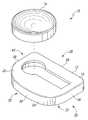
- FIG. 1is a perspective view of a unicompartmental mobile tibial assembly
- FIG. 2is a plan view of the tibial tray of the unicompartmental mobile tibial assembly of FIG. 1 ;
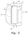
- FIG. 3is a plan view of another embodiment of the tibial tray of the unicompartmental mobile tibial assembly of FIG. 1 ;
- FIG. 4is a plan view of another embodiment of the tibial tray of the unicompartmental mobile tibial assembly of FIG. 1 ;
- FIG. 5is another perspective view of the unicompartmental mobile tibial assembly of FIG. 1 ;
- FIG. 6is a cross-sectional view of the unicompartmental mobile tibial assembly of FIG. 1 having the tibial insert retained in the closed track of the tibial tray;
- FIG. 7is a cross-sectional view of another embodiment of a unicompartmental mobile tibial assembly
- FIG. 8is a perspective view of another embodiment of a unicompartmental mobile tibial assembly
- FIG. 9is a plan view of the tibial tray of the unicompartmental mobile tibial assembly of FIG. 8 ;
- FIG. 10is another perspective view of the unicompartmental mobile tibial assembly of FIG. 8 ;
- FIG. 11is a bottom plan view of the tibial insert of the unicompartmental mobile tibial assembly of FIG. 8 ;
- FIG. 12is a plan view of the unicompartmental mobile tibial assembly of FIG. 8 in an assembled configuration and having a base of the tibial insert removed for clarity;
- FIG. 13is a plan view of another embodiment of the tibial tray of the unicompartmental mobile tibial assembly of FIG. 8 ;
- FIG. 14is a bottom plan view of another embodiment of a tibial insert for use with the tibial tray illustrated in FIG. 13 ;
- FIG. 15is a is a cross-sectional view of the tibial insert of FIG. 14 being retained in the closed track of the tibial tray of FIG. 13 .
- tibial assembliesA number of different embodiments of tibial assemblies are described below. Illustratively, the tibial assemblies are illustrated and described as unicompartmental tibial assemblies intended to replace only one of the two bearing surfaces of a patient's tibia. As such, the tibial assemblies may be used by an orthopaedic surgeon or other healthcare provider during the performance of a unicompartmental knee arthroplasty (UKA) procedure. However, it should be appreciated that the tibial assemblies described herein may also be used during the performance of a total knee arthroplasty (TKA) procedure.
- TKAtotal knee arthroplasty
- a single tibial assemblymay be used for each bearing surface of the tibia thereby improving the overall customizability of the orthopaedic implant compared to typical total knee arthroplasty implants.
- the tibial assemblies described hereinmay be used by the surgeon or other healthcare provider during the performance of an orthopaedic surgical procedure using either conventional or minimally invasive surgical methods.
- the features of the tibial assembliesare described in reference to an orthopaedic knee implant, it should be appreciated that such features are applicable to other types of orthopaedic implants including, but not limited to, hip implants, shoulder implants, elbow implants, spine implants, finger implants, toe implants, wrist implants, and ankle implants.
- a tibial assembly 10includes a tibial tray 12 and a bearing, herein referred to as tibial insert 14 .
- the tibial insert 14is illustratively formed from a polymer material, but may be formed from other materials, such as a ceramic material, a metallic material, a bio-engineered material, or the like, in other embodiments.
- the tibial tray 12is illustratively formed from a metallic material, but may be formed from other materials, such as a ceramic material, a polymer material, a bio-engineered material, or the like, in other embodiments.
- the tibial tray 12is configured to be coupled to a surgically-prepared surface of the proximal end of a patient's tibia (not shown) as described below.
- the tibial tray 12includes a base 16 and a number of anchoring devices 18 , commonly referred to as stems or keels, extending downwardly therefrom.
- anchoring devices 18are embedded in the patient's tibia to thereby secure the tibial tray 12 to the patient's bone.
- the base 16has a generally “D”-shaped top profile and includes an upper surface 20 and a bottom surface 22 from which the anchoring devices 18 extend.
- the base 16has a generally straight side surface 26 defining a inboard side 28 of the tibial tray, a generally curved side surface 30 defining an outboard side 32 of the tibial tray 12 , an end surface 34 defining an anterior side 36 of the tibial tray 12 , and an end surface 38 defining a posterior side 40 of the tibial tray 12 .
- the illustrative tibial assembly 10is but one embodiment of a tibial assembly and that the features and components of the tibial assembly 10 may be used with a tibial assembly configured to replace the medial and/or lateral condyle of a patient's right tibia, as well as, the medial and/or lateral condyle of the patient's left tibia.
- the tibial tray 12includes a track 42 defined in the base 16 .
- the track 42is configured to receive a stem 44 of the tibial insert 14 and retain a portion of the stem 44 therein while allowing the tibial insert 14 to move relative to the tibial tray 12 .
- the track 42is defined by a bottom wall 46 and side walls 48 , 50 .
- An outboard lip 52extends from the side wall 48 a distance 54 .
- a inboard lip 56extends from the side wall 50 a distance 58 .
- the lips 52 , 56extend from the side walls 48 , 50 , respectively, an equal distance (i.e., the distance 54 is substantially equal to the distance 58 ).
- the lips 52 , 56may extend from the side walls 48 , 50 different distances as discussed below in regard to FIGS. 13-15 .
- the illustrative walls 48 , 50have a substantially straight cross-sectional profile. However, in other embodiments, the walls 48 , 50 may have other configurations. For example, the walls 48 , 50 may be convex or concave in some embodiments. Additionally the walls 48 , 50 may be angled or otherwise curved in other embodiments As such, it should be appreciated that the walls 48 , 50 may have any cross-sectional profile shape configured to contact or be positioned adjacent to the corresponding walls of a stem of the tibial insert 14 as discussed in more detail below.
- the outboard lip 52includes a top surface 60 and a bottom surface 62 .
- the inboard lip 56includes a top surface 64 and a bottom surface 66 .
- the top surface 60 of the lip 52is substantially parallel to the bottom surface 62 of the lip 56 .
- the top surface 64 of the inboard lip 56is substantially parallel to the bottom surface 66 of the second lip 56 .
- the top surfaces 60 , 64may not be parallel to the respective bottom surface 62 , 66 .
- the outboard lip 52may include a bottom surface 68 that is oblique or otherwise non-parallel to the top surface 60 .
- the inboard lip 56may include a bottom surface 70 that is oblique or otherwise non-parallel to the top surface 64 .
- the particular angle between the top surfaces 60 , 64 and respective bottom surfaces 68 , 70 of the lips 52 , 56may be selected such that the track 42 is configured to accommodate different embodiments of the tibial insert 14 .
- the lips 52 , 56extend from the respective side walls 48 , 50 so as to define an elongated opening 72 therebetween.
- the elongated opening 72is defined in the upper surface 20 of the base 16 and extends longitudinally in a generally anterior-posterior direction.
- the elongated opening 72i.e., the track 42
- the elongated opening 72may be defined in the upper surface 20 in any orientation. That is, the elongated opening 72 may be defined in the upper surface 20 in a generally anterior-posterior direction, a generally medial-lateral direction, or some combination thereof (i.e., a generally diagonal direction).
- the illustrative elongated opening 72is substantially straight, the tibial tray 12 may include an elongated opening having other configurations in other embodiments. For example, a curved elongated opening may be used in some embodiments.
- the elongated opening 72 of the track 12includes an access opening 74 defined at the posterior end 78 of the track 42 .
- the access opening 74is illustratively defined at the posterior end 78 of the track 42 in FIG. 2
- the access opening 74may be defined at any position along the track 42 and/or offset from the track 42 in other embodiments.
- the access opening 74may be embodied as an access opening 71 positioned at the anterior end 76 of the track 42 , an access opening 73 positioned in a generally central location along the track 42 or otherwise away from the ends 76 , 78 , and/or as an access opening 75 offset from the track 42 but connected thereto.
- the access opening 74provides an aperture through which the stem 44 of the tibial insert 14 may be inserted into the track 42 .
- the access opening 74may have other shapes in other embodiments based on, for example, the shape of the stem 44 of the tibial insert.
- the access opening 74may be embodied as an access opening 77 having a similar rectangular shape.
- the access opening 74may be embodied as an access opening 79 having a similar oval or oblong shape. Further, as discussed above, the access opening 74 may be offset, but connected to, the track 42 . For example, in embodiments wherein the stem 44 has a substantially rectangular bottom profile shape as discussed above, the access opening 74 may be embodied as a rectangular access opening 81 offset to one side of the track 42 so as to form a substantial “L” shape with the track 42 .
- the stem 44 of the tibial insert 14may be inserted into the access opening 81 and subsequently moved into the track 42 such that the tibial insert 14 may move along the track 42 as discussed in more detail below.
- the access opening 74may have any shape that allows the stem 44 of the tibial insert 14 to be received therein and may be located on the top surface 20 of the base 16 in any position relative to, and in connection with, the track 42 (e.g., at any position along the track 42 , offset from the track 42 , etc.).
- the track 42is embodied as a closed track. That is, unlike an open track, one or both of the ends 76 , 78 of the track 42 is not “open” and, as such, does not extend to the respective end surface 34 , 38 of the base 16 . Rather, an end wall 80 of the base 16 is defined between the end 78 of the track 42 and the end surface 38 and/or an end wall 82 is defined between the end 76 of the track 42 and the end surface 34 .
- the ends walls 80 , 82may be of any thickness depending upon such factors as the length of the track 42 , the particular orthopedic application of the assembly 10 , and the like.
- the tibial insert 14includes a base 84 from which the stem 44 extends.
- the base 84includes an upper bearing surface 86 and a bottom surface 88 .
- the stem 44extends downwardly from the bottom surface 88 of the base 84 .
- the upper bearing surface 86 of the tibial insert 14is configured to engage a natural or prosthetic femoral component of a patient's femur. During use, the patient's femur or femoral component articulates on the upper bearing surface 86 .
- the stem 44 of the tibial insert 14includes a flange 90 and a neck 92 connecting the flange 90 to the bottom surface 88 of the base 84 .
- the flange 90has a shape corresponding to the access opening 74 such that the flange 90 of the stem 44 may be inserted into the track 42 via the access opening 74 .
- the flange 90has a generally elliptical or circular bottom profile corresponding to the elliptical or circular shape of the access opening 74 .
- the flange 90may have any one of a number of configurations configured to be received by the access opening 74 and the track 42 .
- the flange 90may be rectangular, triangular, hexagonal or otherwise polygonal, or the like in other embodiments.
- the illustrative flange 90has a width or diameter 94 that is slightly less than the width or diameter 96 of the access opening 74 (see FIG. 2 ) such that the flange 90 may be inserted into the access opening 74 .
- the diameter 94 of the flange 90is greater than the width 98 of the elongated opening 42 defined by the lips 52 , 56 of the track 42 .
- the neck 92has a width or diameter 100 that is slightly less than the width 98 of the elongated opening 42 .
- the flange 90includes an bottom surface 102 and an upper surface 104 .
- the bottom surface 102is substantially parallel to the upper surface 104 .
- the bottom surface 102 and the upper surface 104are substantially parallel to the bottom surface 46 of the track 42 when the tibial insert 14 is received therein.
- the tibial insert 14may include a flange 90 having an upper surface 106 that is oblique to or otherwise not parallel to the a bottom surface 108 of the flange 90 .
- the upper surface 106 of the flange 90is not parallel to the bottom surface 46 of the track 42 when the tibial insert 14 is received therein.
- the tibial insert 14may be coupled to the tibial tray 12 by inserting the stem 44 of the tibial insert 14 into the track 42 of the tibial tray 12 . To do so, the tibial insert 14 is positioned such that the flange 90 of the stem 44 is inserted into the access opening 74 of the track 42 . Once the flange 90 is received by the access opening 74 , the tibial insert 14 may be slid or otherwise moved toward the anterior side 36 of the base 16 .
- the tibial insert 14may be moved along the elongated opening 72 of the track 42 . Additionally, because the diameter 94 of the flange 90 is greater than the width 98 of the elongated opening 72 , the lips 52 , 56 retain the flange 90 , and thereby the tibial insert 14 , in the track 42 . As such, the lips 52 , 56 prevent the tibial insert 14 from lifting off the tibial tray 12 .
- the bottom surface 102 of the flange 90contacts or is otherwise adjacent to the bottom surface 46 of the track 42 .
- the upper surface 104 of the flange 90contacts or is otherwise adjacent to the bottom surfaces 62 , 66 of the lips 52 , 56 , respectively.
- the top surface 106 of the flange 90is oblique or otherwise not parallel to the bottom surface 108 , the top surface 106 contacts or is otherwise adjacent to the bottom surfaces 68 , 70 of the lips 52 , 56 , respectively.
- the tibial insert 14moves back and forth along the track 42 of the tibial tray 12 in a generally anterior-posterior direction.
- the tibial insert 14may be configured to rotate about a center axis defined by the stem 44 .
- the tibial insert 14is configured to rotate while, or in addition to, moving generally anteriorly or posteriorly within the track 42 .
- the access opening 74is located on the base 16 in a manner such that the flange 90 does not exit the track 78 via the access opening 74 during normal use of the tibial assembly 10 by the patient. That is, the access opening 74 is positioned such that the tibial insert 14 is not moved to a position in which the flange 90 is substantially exposed to the access opening 74 during normal flexion and extension of the relevant knee joint of the patient.
- the tibial tray 12includes a track 200 in place of the track 42 described above.
- the track 200is substantially similar to the track 42 and may, or may not, include the access opening 74 .
- the track 200includes an elongated opening 202 , which is similar to elongated opening 72 .
- the elongated opening 202 of the track 200is bounded by lips 204 , 206 extending from the side walls 201 , 203 that define the track 200 .
- the track 200has a width 208 defined by the distance between the side walls 201 , 203 of the track 200 .
- the elongated opening 72has a width 210 , which is less than the width 208 of the track 200 .
- the illustrative tibial insert 14has an oblong shape.
- tibial inserts having other shapesmay be used in other embodiments.
- the tibial insert 14may have a circular shape as shown in FIG. 1 .
- the tibial assembly 10may include a tibial insert 14 having any shape including, but not limited to, a circular shape, an oblong shape, an oval shape, or the like.
- the tibial insert 14includes a stem 112 extending downwardly from the bottom surface 88 of the base 84 .
- the stem 112includes a flange 218 and a neck 214 connecting the flange 218 to the bottom surface 88 of the base 84 .
- the illustrative flange 218has a generally rectangular bottom profile, but may have other shapes in other embodiments.
- the flange 218may have a rectangular bottom profile, a triangular bottom profile, a hexagonal or other polygonal or substantially polygonal bottom profile, or the like in other embodiments.
- the flange 218includes an end 220 extending from the neck 214 a distance 222 and an end 224 extending from the center of the neck 214 a distance 226 .
- the distances 222 , 226are substantially equal, but may be different in other embodiments as discussed below in regard to FIGS. 13-15 .
- the illustrative ends 220 , 224 of the flange 218are substantially straight. However, in other embodiments, the ends 220 , 224 may be curved or otherwise not straight, as shown in phantom in FIG. 11 , to improve the ease of inserting the tibial insert 14 into the track 200 as discussed below.
- the flange 218has a length 228 which is greater than its width 230 .
- the flange 218is configured such that the length 228 of the flange 218 is slightly smaller than the width 208 of the bottom wall 205 of the track 200 but greater than the width 210 of the elongated opening 202 of the track 200 . Additionally, the width 230 of the flange 218 is slightly less than the width 210 of the elongated opening 202 .
- the flange 218includes dimensions (i.e., the length 228 and width 230 ) that allow the flange 218 of the stem 44 to be inserted into the track 200 in a longitudinal orientation as discussed in more detail below.
- the flange 218includes an upper surface 232 and a bottom surface 234 .
- the upper surface 232is substantially parallel to the bottom surface 234 .
- the upper surface 232 and the bottom surface 234are substantially parallel to the bottom surface 205 of the track 200 when the tibial insert 14 is received therein.
- the surfaces 232 , 234 of the tibial insert 14may not be parallel to each other.
- the lips 204 , 206 of the track 200may also include oblique or otherwise non-parallel bottom surfaces similar to the bottoms surfaces 68 , 70 of the lips 52 , 56 as illustrated in and described above in regard to FIG. 7 .
- the tibial insert 14may be coupled to the tibial tray 12 by inserting the stem 212 of the tibial insert 14 into the track 200 of the tibial tray 12 . To do so, as shown in FIG. 12 , the tibial insert 14 is positioned in an initial orientation 250 such that the flange 218 is in registry with the elongated opening 202 . For example, as shown in FIG.
- the tibial insert 14may be positioned in a similar anterior-posterior direction (i.e., initial orientation 250 ) with respect to the tibial insert 12 . Because the width 230 of the flange 218 (see FIG. 9 ) is slightly less than the width of the elongated opening 202 , the flange 218 of the stem 212 may be inserted into track 200 .
- the tibial insert 12is turned in a generally rotational direction as indicated by arrow 254 or otherwise moved to another orientation 252 such that the flange 218 is substantially orthogonal with respect to the elongated opening 202 .
- the ends 220 , 224are curved or generally rounded to thereby allow or otherwise increase the ease with which the tibial insert 14 may be moved to the retained orientation 252 (i.e., the ends 220 , 224 are not restricted by the track's walls 201 , 203 ).
- the flange 218is retained in the track 200 via the lips 204 , 206 , which define the elongated opening 202 when in the retrained orientation 252 . As such, the lips 204 , 206 prevent the tibial insert 14 from lifting off the tibial tray 12 . Additionally, as with the stem 44 , because the diameter of the neck 214 of the stem 212 is less than the width 210 of the elongated opening 202 , the tibial insert 14 may be moved along the elongated opening 202 of the tibial tray 12 while being retained in the track 200 .
- the tibial insert 14may be removed from the tibial tray 12 by reversing the above-described procedure. That is, the tibial insert 14 may be de-coupled from the tibial tray 12 by turning or otherwise moving the tibial insert 14 into the initial position such that the flange 212 is in registry with the elongated opening 202 of the track 200 . Once so positioned, the tibial insert 14 may be removed from the track 200 by lifting the tibial insert 14 off of the tibial tray 14 .
- the tibial insert 14moves along the track 200 of the tibial tray 12 in a generally anterior-posterior direction.
- the tibial tray 12may be configured to move some amount in a generally medial-lateral direction while, or in addition to, moving in a generally anterior-posterior direction
- the tibial tray 12includes a track 300 in place of the track 42 .
- the track 300is substantially similar to the track 200 described above in regard to FIGS. 6-9 and includes an elongated opening 302 defined on the top surface 20 of the tibial tray 14 .
- the elongated opening 302 of the track 300is defined by a pair of lips 304 , 306 extending from the sidewalls 301 , 303 that define the track 300 .
- the lips 304 , 306extend from the sidewalls 301 , 303 different distances.
- the outboard lip 304extends from the sidewall 301 a distance 308 and the inboard lip 306 extends from the sidewall 303 a distance 310 .
- the distance 310is greater than the distance 308 such that the cross-sectional area 312 defined under the inboard lip 306 is greater than the cross-section area 314 defined under the outboard lip 304 .
- the track's bottom wall 346has a width 316 defined by the distance between the side walls 301 , 303 that is greater than the width 318 of the elongated opening 302 , but is offset relative to the opening 302 as shown in FIG. 13 .
- the tibial insert 14includes a stem 320 extending downwardly from the bottom surface 88 .
- the stem 320includes a flange 322 and a neck 324 connecting the flange 322 to the bottom surface 88 of the tibial insert 14 .
- the flange 322has a generally rectangular bottom profile.
- the flange 322may have other shapes in other embodiments.
- the flange 322may have a rectangular bottom profile, a triangular bottom profile, a hexagonal or other polygonal or substantially polygonal bottom profile, or the like in other embodiments.
- the flange 322includes ends 326 , 328 .
- the end 328extends from the neck 324 farther than the end 326 . That is, the shorter end 326 extends from the neck 324 a distance 222 and the longer end 328 extends from the neck 324 a distance 332 , which is greater than the distance 222 .
- the illustrative ends 326 , 328are substantially straight, but may be curved or otherwise not straight in other embodiments similar to the flange 220 illustrated in FIG. 11 .
- the flange 322has a length 334 which is greater than its width 360 .
- the flange 322is configured such that the length 334 of the flange 322 is slightly smaller than the width 316 of the track's bottom wall 346 but greater than the width 318 of the elongated opening 302 of the track 300 .
- the width 336 of the flange 322is slightly less than the width 318 of the elongated opening 302 .
- the flange 322includes dimensions (i.e., the length 334 and width 336 ) that allows the flange 322 of the stem 320 to be inserted into the track 300 in a longitudinal orientation as discussed in more detail below.
- the flange 322includes an upper surface 340 and a bottom surface 342 .
- the upper surface 340is substantially parallel to the bottom surface 342 .
- the upper surface 340 and the bottom surface 342are substantially parallel to the bottom wall 346 of the track 300 when the tibial insert 14 is received therein.
- the surfaces 340 , 342 of the tibial insert 14may not be parallel to each other.
- the lips 304 , 306 of the track 300may also include oblique or otherwise non-parallel bottom surfaces similar to the bottoms surfaces 68 , 70 of the lips 52 , 56 as illustrated in and described above in regard to FIG. 7 .
- the tibial insert 14may be coupled to the tibial tray 12 by inserting the stem 320 of the tibial insert 14 into the track 300 of the tibial tray 12 in a similar manner as described above in regard to FIG. 12 . To do so, the tibial insert 14 is positioned in an initial orientation such that the flange 320 is in registry with the elongated opening 302 (i.e., similar to orientation 250 shown in FIG. 12 ). For example, in the illustrative embodiment of FIG.
- the tibial insert 14may be positioned in a similar anterior-posterior direction with respect to the tibial tray 12 . Because the width 336 of the flange 322 is slightly less than the width of the elongated opening 318 , the flange 322 of the stem 320 may be inserted into track 200 .
- the tibial insert 12is turned or otherwise moved to another orientation such that the flange 322 is substantially orthogonal with respect to the elongated opening 302 (i.e., similar to orientation 252 shown in FIG. 12 ).
- the tibial insert 14may only be turned to the orientation wherein the longer end 328 is received in the larger cross-sectional area 312 defined under the lip 306 of the track 300 .
- the longer end 328is configured to contact the sidewall 301 of the track 300 prior to reaching a latitudinal orientation.
- the configuration of the track 300 and the flange 322ensure that the tibial insert 14 may be coupled to the tibial tray 12 in only a single orientation. That is, the flange 322 of the tibial insert 14 may only be received by the track 300 in an orientation wherein the shorter end 326 is positioned adjacent the sidewall 301 and the longer end 328 is positioned adjacent the sidewall 303 . As such, the likelihood of misaligning tibial trays having asymmetric features is reduced.
- the flange 332is retained in the track 300 via the lips 304 , 306 , which define the elongated opening 302 .
- the lips 304 , 306prevent the tibial insert 14 from lifting off the tibial tray 12 .
- the tibial insert 14may be moved along the elongated opening 302 of the track 300 while being retained therein.
- the tibial insert 14may be removed from the tibial tray 12 by reversing the above-described procedure. That is, the tibial insert 14 may be de-coupled from the tibial tray 12 by turning or otherwise moving the tibial insert 14 into the initial position such that the flange 322 is in registry with the elongated opening 302 of the track 300 . Once so positioned, the tibial insert 14 may be removed from the track 300 by lifting the tibial insert 14 off of the tibial tray 14 .
- the tibial insert 14moves along the track 300 of the tibial tray 12 in a generally anterior-posterior direction.
- the tibial tray 12may be configured to move some amount in a generally medial-lateral direction while, or in addition to, moving in a generally anterior-posterior direction.
Landscapes
- Health & Medical Sciences (AREA)
- Orthopedic Medicine & Surgery (AREA)
- Physical Education & Sports Medicine (AREA)
- Cardiology (AREA)
- Oral & Maxillofacial Surgery (AREA)
- Transplantation (AREA)
- Engineering & Computer Science (AREA)
- Biomedical Technology (AREA)
- Heart & Thoracic Surgery (AREA)
- Vascular Medicine (AREA)
- Life Sciences & Earth Sciences (AREA)
- Animal Behavior & Ethology (AREA)
- General Health & Medical Sciences (AREA)
- Public Health (AREA)
- Veterinary Medicine (AREA)
- Prostheses (AREA)
- Magnetic Resonance Imaging Apparatus (AREA)
- Toys (AREA)
- Surgical Instruments (AREA)
Abstract
Description
Claims (21)
Priority Applications (4)
| Application Number | Priority Date | Filing Date | Title |
|---|---|---|---|
| US12/049,750US8764841B2 (en) | 2007-03-30 | 2008-03-17 | Mobile bearing assembly having a closed track |
| DE602008003468TDE602008003468D1 (en) | 2007-03-30 | 2008-03-29 | Mobile tibial support arrangement |
| AT08251211TATE488201T1 (en) | 2007-03-30 | 2008-03-29 | MOBILE TIBIAL SUPPORT ARRANGEMENT |
| EP08251211AEP1974695B1 (en) | 2007-03-30 | 2008-03-29 | Mobile tibial bearing assembly |
Applications Claiming Priority (2)
| Application Number | Priority Date | Filing Date | Title |
|---|---|---|---|
| US90912607P | 2007-03-30 | 2007-03-30 | |
| US12/049,750US8764841B2 (en) | 2007-03-30 | 2008-03-17 | Mobile bearing assembly having a closed track |
Publications (2)
| Publication Number | Publication Date |
|---|---|
| US20080243261A1 US20080243261A1 (en) | 2008-10-02 |
| US8764841B2true US8764841B2 (en) | 2014-07-01 |
Family
ID=39523327
Family Applications (1)
| Application Number | Title | Priority Date | Filing Date |
|---|---|---|---|
| US12/049,750Active2028-10-21US8764841B2 (en) | 2007-03-30 | 2008-03-17 | Mobile bearing assembly having a closed track |
Country Status (4)
| Country | Link |
|---|---|
| US (1) | US8764841B2 (en) |
| EP (1) | EP1974695B1 (en) |
| AT (1) | ATE488201T1 (en) |
| DE (1) | DE602008003468D1 (en) |
Cited By (2)
| Publication number | Priority date | Publication date | Assignee | Title |
|---|---|---|---|---|
| US20170258599A1 (en)* | 2009-07-10 | 2017-09-14 | Aesculap Ag | Knee Joint Prosthesis and Related Method |
| US10709460B2 (en) | 2016-08-01 | 2020-07-14 | Howmedica Osteonics Corp. | Centering guide system for arthroplasty |
Families Citing this family (43)
| Publication number | Priority date | Publication date | Assignee | Title |
|---|---|---|---|---|
| US9017381B2 (en) | 2007-04-10 | 2015-04-28 | Biomet Sports Medicine, Llc | Adjustable knotless loops |
| US8298262B2 (en) | 2006-02-03 | 2012-10-30 | Biomet Sports Medicine, Llc | Method for tissue fixation |
| US8118836B2 (en) | 2004-11-05 | 2012-02-21 | Biomet Sports Medicine, Llc | Method and apparatus for coupling soft tissue to a bone |
| US8303604B2 (en) | 2004-11-05 | 2012-11-06 | Biomet Sports Medicine, Llc | Soft tissue repair device and method |
| US8137382B2 (en) | 2004-11-05 | 2012-03-20 | Biomet Sports Medicine, Llc | Method and apparatus for coupling anatomical features |
| US8361113B2 (en) | 2006-02-03 | 2013-01-29 | Biomet Sports Medicine, Llc | Method and apparatus for coupling soft tissue to a bone |
| US7658751B2 (en) | 2006-09-29 | 2010-02-09 | Biomet Sports Medicine, Llc | Method for implanting soft tissue |
| US7749250B2 (en) | 2006-02-03 | 2010-07-06 | Biomet Sports Medicine, Llc | Soft tissue repair assembly and associated method |
| US7905904B2 (en) | 2006-02-03 | 2011-03-15 | Biomet Sports Medicine, Llc | Soft tissue repair device and associated methods |
| US7909851B2 (en) | 2006-02-03 | 2011-03-22 | Biomet Sports Medicine, Llc | Soft tissue repair device and associated methods |
| US8088130B2 (en) | 2006-02-03 | 2012-01-03 | Biomet Sports Medicine, Llc | Method and apparatus for coupling soft tissue to a bone |
| US8128658B2 (en) | 2004-11-05 | 2012-03-06 | Biomet Sports Medicine, Llc | Method and apparatus for coupling soft tissue to bone |
| US8652171B2 (en) | 2006-02-03 | 2014-02-18 | Biomet Sports Medicine, Llc | Method and apparatus for soft tissue fixation |
| US11311287B2 (en) | 2006-02-03 | 2022-04-26 | Biomet Sports Medicine, Llc | Method for tissue fixation |
| US10517587B2 (en) | 2006-02-03 | 2019-12-31 | Biomet Sports Medicine, Llc | Method and apparatus for forming a self-locking adjustable loop |
| US8562647B2 (en) | 2006-09-29 | 2013-10-22 | Biomet Sports Medicine, Llc | Method and apparatus for securing soft tissue to bone |
| US8801783B2 (en) | 2006-09-29 | 2014-08-12 | Biomet Sports Medicine, Llc | Prosthetic ligament system for knee joint |
| US8597327B2 (en) | 2006-02-03 | 2013-12-03 | Biomet Manufacturing, Llc | Method and apparatus for sternal closure |
| US11259792B2 (en) | 2006-02-03 | 2022-03-01 | Biomet Sports Medicine, Llc | Method and apparatus for coupling anatomical features |
| US8562645B2 (en) | 2006-09-29 | 2013-10-22 | Biomet Sports Medicine, Llc | Method and apparatus for forming a self-locking adjustable loop |
| US9468433B2 (en) | 2006-02-03 | 2016-10-18 | Biomet Sports Medicine, Llc | Method and apparatus for forming a self-locking adjustable loop |
| US9078644B2 (en) | 2006-09-29 | 2015-07-14 | Biomet Sports Medicine, Llc | Fracture fixation device |
| US8968364B2 (en) | 2006-02-03 | 2015-03-03 | Biomet Sports Medicine, Llc | Method and apparatus for fixation of an ACL graft |
| US11259794B2 (en) | 2006-09-29 | 2022-03-01 | Biomet Sports Medicine, Llc | Method for implanting soft tissue |
| US8672969B2 (en) | 2006-09-29 | 2014-03-18 | Biomet Sports Medicine, Llc | Fracture fixation device |
| EP2124778B1 (en) | 2007-02-21 | 2019-09-25 | Benvenue Medical, Inc. | Devices for treating the spine |
| US12245759B2 (en) | 2008-08-22 | 2025-03-11 | Biomet Sports Medicine, Llc | Method and apparatus for coupling soft tissue to bone |
| US12419632B2 (en) | 2008-08-22 | 2025-09-23 | Biomet Sports Medicine, Llc | Method and apparatus for coupling anatomical features |
| US8343227B2 (en)* | 2009-05-28 | 2013-01-01 | Biomet Manufacturing Corp. | Knee prosthesis assembly with ligament link |
| US8894715B2 (en) | 2009-05-28 | 2014-11-25 | Biomet Manufacturing, Llc | Knee prosthesis |
| US12096928B2 (en) | 2009-05-29 | 2024-09-24 | Biomet Sports Medicine, Llc | Method and apparatus for coupling soft tissue to a bone |
| US9675464B2 (en) | 2010-10-28 | 2017-06-13 | Gerald J. Jerry | Tibial tray system and method of implantation |
| US12329373B2 (en) | 2011-05-02 | 2025-06-17 | Biomet Sports Medicine, Llc | Method and apparatus for soft tissue fixation |
| US9357991B2 (en) | 2011-11-03 | 2016-06-07 | Biomet Sports Medicine, Llc | Method and apparatus for stitching tendons |
| US9381013B2 (en) | 2011-11-10 | 2016-07-05 | Biomet Sports Medicine, Llc | Method for coupling soft tissue to a bone |
| US9314241B2 (en) | 2011-11-10 | 2016-04-19 | Biomet Sports Medicine, Llc | Apparatus for coupling soft tissue to a bone |
| US9744046B2 (en)* | 2012-02-07 | 2017-08-29 | Biomet Manufacturing, Llc | Locking screw assembly |
| US8906102B2 (en) | 2012-05-31 | 2014-12-09 | Howmedica Osteonics Corp. | Lateral entry insert for cup trial |
| US8663334B2 (en) | 2012-05-31 | 2014-03-04 | Howmedica Osteonics Corp. | Lateral entry insert for cup trial |
| US9918827B2 (en) | 2013-03-14 | 2018-03-20 | Biomet Sports Medicine, Llc | Scaffold for spring ligament repair |
| ES2930135T3 (en)* | 2013-05-01 | 2022-12-07 | Ndsu Res Foundation | Improved Apparatus and Method for Ankle Replacement |
| WO2017155995A1 (en)* | 2016-03-08 | 2017-09-14 | Genesis Innovation Group, Llc | Knee prosthesis with modular tibial inserts |
| US10835381B2 (en)* | 2017-07-28 | 2020-11-17 | Active Implants LLC | Two-piece floating joint replacement device with a rigid backing material |
Citations (163)
| Publication number | Priority date | Publication date | Assignee | Title |
|---|---|---|---|---|
| US3506982A (en) | 1965-06-21 | 1970-04-21 | Cleveland Clinic | Endoprosthetic joints |
| US3605123A (en) | 1969-04-29 | 1971-09-20 | Melpar Inc | Bone implant |
| US3855638A (en) | 1970-06-04 | 1974-12-24 | Ontario Research Foundation | Surgical prosthetic device with porous metal coating |
| US3906550A (en) | 1973-12-27 | 1975-09-23 | William Rostoker | Prosthetic device having a porous fiber metal structure |
| US3953899A (en) | 1973-05-17 | 1976-05-04 | Chas. F. Thackray Limited | Knee arthroplasty |
| US4016606A (en) | 1975-07-14 | 1977-04-12 | Research Corporation | Knee joint prosthesis |
| US4205400A (en) | 1978-12-04 | 1980-06-03 | Zimmer Usa, Inc. | Metallo-polymeric prosthesis with cavitied interconnection |
| US4207627A (en) | 1979-01-18 | 1980-06-17 | Cloutier Jean Marie | Knee prosthesis |
| US4213816A (en) | 1978-06-12 | 1980-07-22 | Glasrock Products, Inc. | Method for bonding porous coating to rigid structural member |
| US4216549A (en)* | 1977-06-02 | 1980-08-12 | Purdue Research Foundation | Semi-stable total knee prosthesis |
| US4224696A (en) | 1978-09-08 | 1980-09-30 | Hexcel Corporation | Prosthetic knee |
| US4224697A (en) | 1978-09-08 | 1980-09-30 | Hexcel Corporation | Constrained prosthetic knee |
| US4340978A (en) | 1979-07-02 | 1982-07-27 | Biomedical Engineering Corp. | New Jersey meniscal bearing knee replacement |
| US4454612A (en) | 1980-05-07 | 1984-06-19 | Biomet, Inc. | Prosthesis formation having solid and porous polymeric components |
| US4470158A (en) | 1978-03-10 | 1984-09-11 | Biomedical Engineering Corp. | Joint endoprosthesis |
| US4479271A (en) | 1981-10-26 | 1984-10-30 | Zimmer, Inc. | Prosthetic device adapted to promote bone/tissue ingrowth |
| US4501031A (en) | 1981-01-22 | 1985-02-26 | Zimmer, Inc. | Metal and plastic composite tibial component for knee joint |
| EP0135319A2 (en) | 1983-08-24 | 1985-03-27 | ARTHROPLASTY RESEARCH & DEVELOPMENT (PTY) LTD. | Knee prosthesis |
| US4568348A (en) | 1982-03-13 | 1986-02-04 | Chas. F. Thackray Limited | Knee prosthesis |
| US4589883A (en) | 1983-06-06 | 1986-05-20 | Pfizer Hospital Products Group, Inc. | Femoral hip prosthesis |
| US4636219A (en) | 1985-12-05 | 1987-01-13 | Techmedica, Inc. | Prosthesis device fabrication |
| US4718413A (en) | 1986-12-24 | 1988-01-12 | Orthomet, Inc. | Bone cutting guide and methods for using same |
| US4719908A (en) | 1986-08-15 | 1988-01-19 | Osteonics Corp. | Method and apparatus for implanting a prosthetic device |
| US4728332A (en) | 1984-11-28 | 1988-03-01 | Albrektsson Bjoern | Artificial menisco-tibial joint |
| US4743261A (en) | 1986-01-27 | 1988-05-10 | Epinette Jean Alain | Tibial component for unicompartmental knee prosthesis for a cementness implantation |
| US4795468A (en) | 1987-12-23 | 1989-01-03 | Zimmer, Inc. | Mechanism and method for locking a bearing insert to the base of a prosthetic implant |
| EP0327387A2 (en) | 1988-02-05 | 1989-08-09 | Btg International Limited | Orthopaedic joint components, tools and methods |
| EP0328463A1 (en) | 1988-01-29 | 1989-08-16 | Christian Broc | Femoral implant for a two-part knee joint prosthesis |
| US4911721A (en) | 1984-11-28 | 1990-03-27 | Aendergaten 3 | Joint prosthesis |
| US4936847A (en) | 1988-12-27 | 1990-06-26 | Johnson & Johnson Orthopaedics, Inc. | Revision knee prosthesis |
| US4944757A (en) | 1988-11-07 | 1990-07-31 | Martinez David M | Modulator knee prosthesis system |
| US4950298A (en) | 1988-04-08 | 1990-08-21 | Gustilo Ramon B | Modular knee joint prosthesis |
| US4997445A (en) | 1989-12-08 | 1991-03-05 | Zimmer, Inc. | Metal-backed prosthetic implant with enhanced bonding of polyethylene portion to metal base |
| US5019103A (en) | 1990-02-05 | 1991-05-28 | Boehringer Mannheim Corporation | Tibial wedge system |
| WO1991010412A1 (en) | 1990-01-08 | 1991-07-25 | Zimmer, Inc. | Knee joint prosthesis |
| US5047058A (en) | 1988-04-08 | 1991-09-10 | Smith & Nephew Richards, Inc. | System of inserts for the tibial component of a knee prosthesis |
| US5108452A (en) | 1989-02-08 | 1992-04-28 | Smith & Nephew Richards Inc. | Modular hip prosthesis |
| US5152797A (en) | 1991-10-25 | 1992-10-06 | Johnson & Johnson Orthopaedics, Inc. | Modular prosthesis |
| US5201769A (en) | 1991-09-23 | 1993-04-13 | Schutzer Steven F | Hip stem with proximal build-up blocks |
| US5226915A (en) | 1992-04-03 | 1993-07-13 | Bertin Kim C | Femoral prosthesis component system for knee replacement surgery |
| US5263987A (en) | 1989-08-25 | 1993-11-23 | Shah Mrugesh K | Method and apparatus for arthroscopically replacing a bone joint |
| US5282868A (en) | 1991-06-17 | 1994-02-01 | Andre Bahler | Prosthetic arrangement for a complex joint, especially knee joint |
| US5330532A (en) | 1990-11-09 | 1994-07-19 | Chitranjan Ranawat | Knee joint prosthesis |
| USD354810S (en) | 1993-08-17 | 1995-01-24 | Zimmer, Inc. | Surgical parallel drill guide |
| US5395401A (en)* | 1991-06-17 | 1995-03-07 | Bahler; Andre | Prosthetic device for a complex joint |
| USD357534S (en) | 1993-12-15 | 1995-04-18 | Zimmer, Inc. | Surgical parallel drill guide instrument |
| FR2702369B1 (en) | 1993-03-10 | 1995-05-05 | Gilles Voydeville | Knee prosthesis. |
| USD359557S (en) | 1994-02-09 | 1995-06-20 | Zimmer, Inc. | Orthopaedic drill guide |
| WO1995024874A1 (en) | 1994-03-17 | 1995-09-21 | Euros S.A. | Knee joint prosthesis assembly |
| US5458637A (en) | 1994-11-21 | 1995-10-17 | Zimmer, Inc. | Orthopaedic base component with modular augmentation block |
| BE1008201A3 (en) | 1992-06-26 | 1996-02-13 | Cremascoli G Srl | Total knee prosthesis. |
| FR2721820B1 (en) | 1994-06-30 | 1996-12-13 | Ysebaert Sa | KNEE PROSTHETIC JOINT, IN PARTICULAR ONE-COMPARTMENTAL KNEE PROSTHESIS, OR JOINT PROSTHESIS |
| US5609639A (en)* | 1991-02-04 | 1997-03-11 | Walker; Peter S. | Prosthesis for knee replacement |
| US5609640A (en) | 1991-07-05 | 1997-03-11 | Johnson; David P. | Patella prostheses |
| WO1997016129A1 (en) | 1995-11-02 | 1997-05-09 | Masini Michael A | Bone cutting guides for use in the implantation of prosthetic joint components |
| US5658341A (en) | 1993-03-10 | 1997-08-19 | Medinov S.A. | Tibial implant for a knee prosthesis |
| US5702459A (en) | 1994-05-13 | 1997-12-30 | Smith & Nephew Richards France | Trochlea implant for a femoro-patellar prosthesis |
| US5702458A (en) | 1994-12-09 | 1997-12-30 | New York Society For The Ruptured And Crippled Maintaining The Hospital For Special Surgery | Joint prosthesis |
| FR2663536B1 (en) | 1990-06-22 | 1998-02-13 | Implants Instr Ch Fab | TOTAL SLIDING TYPE KNEE PROSTHESIS. |
| US5755801A (en)* | 1993-07-16 | 1998-05-26 | Walker; Peter Stanley | Prostheses for knee replacement |
| US5800560A (en) | 1988-09-09 | 1998-09-01 | Draenert; Klaus | Hip prosthesis with adjustable head |
| US5810827A (en) | 1994-09-02 | 1998-09-22 | Hudson Surgical Design, Inc. | Method and apparatus for bony material removal |
| US5824106A (en) | 1996-04-11 | 1998-10-20 | Tornier Sa | Ankle prosthesis |
| US5855296A (en) | 1996-11-07 | 1999-01-05 | Mccann; Gerald P. | Combined carbonator and water pressure booster apparatus |
| US5871541A (en) | 1993-11-23 | 1999-02-16 | Plus Endoprothetik, Ag | System for producing a knee-joint endoprosthesis |
| US5879354A (en) | 1994-09-02 | 1999-03-09 | Hudson Surgical Design, Inc. | Prosthetic implant |
| US5888034A (en) | 1990-07-13 | 1999-03-30 | Greenberg; Alex M. | Drill mountable drill guide |
| US5957979A (en) | 1997-12-12 | 1999-09-28 | Bristol-Myers Squibb Company | Mobile bearing knee with metal on metal interface |
| US6004351A (en) | 1996-09-14 | 1999-12-21 | Mizuho Ika Kogyo Kabushiki Kaisha | Prosthetic knee joint |
| US6010534A (en)* | 1997-09-25 | 2000-01-04 | Johnson & Johnson Professional, Inc. | Rotatable tibial prosthesis with keyed axial securement |
| US6019767A (en) | 1990-07-16 | 2000-02-01 | Arthrotek | Tibial guide |
| WO2000013616A1 (en) | 1998-09-04 | 2000-03-16 | Merchant Alan C | Modular knee implant system |
| US6039764A (en)* | 1997-08-18 | 2000-03-21 | Arch Development Corporation | Prosthetic knee with adjusted center of internal/external rotation |
| US6106529A (en) | 1998-12-18 | 2000-08-22 | Johnson & Johnson Professional, Inc. | Epicondylar axis referencing drill guide |
| US6123728A (en) | 1997-09-17 | 2000-09-26 | Smith & Nephew, Inc. | Mobile bearing knee prosthesis |
| US6139581A (en) | 1997-06-06 | 2000-10-31 | Depuy Orthopaedics, Inc. | Posterior compensation tibial tray |
| US6171340B1 (en) | 1998-02-27 | 2001-01-09 | Mcdowell Charles L. | Method and device for regenerating cartilage in articulating joints |
| GB2355935A (en) | 1999-11-06 | 2001-05-09 | Corin Ltd | Unicompartmental knee prosthesis |
| US6254604B1 (en) | 1990-07-16 | 2001-07-03 | Arthrotek, Inc. | Tibial guide |
| EP0709075B1 (en) | 1994-10-27 | 2001-08-29 | Merck Biomaterial France | Femoral implant for an unicompartimental knee prosthesis |
| WO2001070143A1 (en) | 2000-03-21 | 2001-09-27 | Merchant Alan C | Patellar bearing implant |
| US6296666B1 (en)* | 2000-03-13 | 2001-10-02 | Encore Medical Corporation | Mobile bearing knee with center post |
| US6361564B1 (en)* | 1999-02-02 | 2002-03-26 | Aesculap | Total knee joint comprising an insert movable relative to a tenon |
| US20020055784A1 (en) | 1999-10-07 | 2002-05-09 | Albert Burstein | Composite bearing inserts for total knee joints |
| US6419707B1 (en) | 1999-08-10 | 2002-07-16 | Sulzer Orthopedics Ltd. | Artificial knee with rotatable meniscus |
| US6428577B1 (en) | 1998-05-20 | 2002-08-06 | Smith & Nephew, Inc. | Mobile bearing knee prosthesis |
| JP2002272756A (en) | 2001-03-16 | 2002-09-24 | Yoshio Koga | Instrument for anterior cruciate ligament based reconstructive surgery of knee joint and shank-side fixing instrument of repaired ligament shank |
| DE10012060C2 (en) | 2000-03-14 | 2002-10-31 | Saint Paul Bernd | Endoprosthesis for a knee joint |
| DE10053623C2 (en) | 2000-10-29 | 2002-11-21 | Martin Aicher | Unicondylar knee prosthesis |
| US6494914B2 (en) | 2000-12-05 | 2002-12-17 | Biomet, Inc. | Unicondylar femoral prosthesis and instruments |
| US20030009232A1 (en) | 1999-03-01 | 2003-01-09 | Robert Metzger | Floating bearing knee joint prosthesis with a fixed tibial post |
| US6506215B1 (en) | 1998-05-12 | 2003-01-14 | Patrick Letot | Synthetic knee system |
| US20030028196A1 (en) | 2000-01-14 | 2003-02-06 | Bonutti Peter M. | Method of performing surgery |
| US20030033018A1 (en) | 2001-08-07 | 2003-02-13 | Merchant Alan C. | Patello-femoral joint arthroplasty |
| US6520964B2 (en) | 2000-05-01 | 2003-02-18 | Std Manufacturing, Inc. | System and method for joint resurface repair |
| US20030120346A1 (en) | 2001-08-07 | 2003-06-26 | James Mercinek | Patellar prosthetic arrangement and associated surgical method |
| EP1329205A1 (en) | 2002-01-18 | 2003-07-23 | Finsbury (Development) Limited | Prosthesis |
| US6602292B2 (en)* | 2001-03-06 | 2003-08-05 | Centerpulse Orthopedic Inc. | Mobile bearing patella prosthesis |
| WO2003068119A2 (en) | 2002-02-14 | 2003-08-21 | Abendschein Walter F | Method and instrumentation for patello-femoral joint replacement |
| US20030158606A1 (en) | 2002-02-20 | 2003-08-21 | Coon Thomas M. | Knee arthroplasty prosthesis and method |
| US20030187510A1 (en) | 2001-05-04 | 2003-10-02 | Hyde Edward R. | Mobile bearing prostheses |
| US20030195633A1 (en) | 2001-05-04 | 2003-10-16 | Hyde Edward R. | Magnetic array implant and prosthesis insert |
| US6660039B1 (en)* | 1998-05-20 | 2003-12-09 | Smith & Nephew, Inc. | Mobile bearing knee prosthesis |
| WO2004001569A2 (en) | 2002-06-21 | 2003-12-31 | Cedara Software Corp. | Computer assisted system and method for minimal invasive hip, uni knee and total knee replacement |
| EP1374782A2 (en) | 2002-06-21 | 2004-01-02 | Depuy Products, Inc. | Prosthesis cutting guide and cutting tool |
| US20040006394A1 (en) | 2002-05-08 | 2004-01-08 | Lipman Joseph D. | Self-aligning knee prosthesis |
| US20040039447A1 (en) | 2000-03-14 | 2004-02-26 | Ultra Tec Manufacturing, Inc. | Cartilage repair plug |
| US6702821B2 (en) | 2000-01-14 | 2004-03-09 | The Bonutti 2003 Trust A | Instrumentation for minimally invasive joint replacement and methods for using same |
| US6730128B2 (en) | 2001-04-17 | 2004-05-04 | Exactech, Inc. | Prosthetic knee joint |
| US20040107000A1 (en) | 2000-08-28 | 2004-06-03 | Felt Jeffrey C. | Method and system for mammalian joint resurfacing |
| US20040143338A1 (en) | 2003-01-21 | 2004-07-22 | Brian Burkinshaw | Multi-piece modular patellar prosthetic system |
| US6770078B2 (en) | 2000-01-14 | 2004-08-03 | Peter M. Bonutti | Movable knee implant and methods therefor |
| EP1442728A2 (en) | 2003-02-03 | 2004-08-04 | Zimmer Technology, Inc. | Mobile bearing unicompartmental knee |
| US20040153066A1 (en) | 2003-02-03 | 2004-08-05 | Coon Thomas M. | Apparatus for knee surgery and method of use |
| US20040167630A1 (en) | 2003-02-20 | 2004-08-26 | Rolston Lindsey R. | Device and method for bicompartmental arthroplasty |
| US20040193280A1 (en) | 2003-02-03 | 2004-09-30 | Webster Vincent A. | Mobile bearing unicondylar tibial knee prosthesis |
| US20040254645A1 (en) | 2003-06-16 | 2004-12-16 | Uri Arnin | Prosthetic patellar implant |
| US20050015153A1 (en)* | 2002-05-24 | 2005-01-20 | Medicine Lodge, Inc. | Implants and related methods and apparatus for securing an implant on an articulating surface of an orthopedic joint |
| WO2005009298A1 (en) | 2003-07-17 | 2005-02-03 | Exactech, Inc. | Mobile bearing knee prosthesis |
| WO2005025451A2 (en) | 2003-09-11 | 2005-03-24 | Advanced Bio Surfaces, Inc. | Method and materials for interpositional arthroplasty implant |
| WO2005037065A2 (en) | 2003-10-14 | 2005-04-28 | Hfsc Company | Surgical drill guide |
| US20050096747A1 (en) | 2003-10-29 | 2005-05-05 | Tuttle David R. | Tibial knee prosthesis |
| US20050119664A1 (en) | 2000-03-17 | 2005-06-02 | Kinamed, Inc. | Marking template for installing a custom replacement device for resurfacing a femur and associated installation method |
| US20050143831A1 (en)* | 2003-12-30 | 2005-06-30 | Medicinelodge, Inc. | Tibial condylar hemiplasty implants, anchor assemblies, and related methods |
| US20050149041A1 (en) | 2003-11-14 | 2005-07-07 | Mcginley Brian J. | Adjustable surgical cutting systems |
| EP1557144A1 (en) | 2004-01-23 | 2005-07-27 | DePuy Orthopaedics, Inc. | Bone protector kit |
| WO2005069957A2 (en) | 2004-01-20 | 2005-08-04 | Alexander Michalow | Unicondylar knee implant |
| US20050177242A1 (en) | 2004-01-12 | 2005-08-11 | Lotke Paul A. | Patello-femoral prosthesis |
| US20050197709A1 (en) | 2004-02-27 | 2005-09-08 | Roberto Schaefer | Medial and lateral femoral implants for single-compartment knee prosthesis |
| US20050234465A1 (en) | 2004-03-31 | 2005-10-20 | Mccombs Daniel L | Guided saw with pins |
| US20050240273A1 (en) | 2002-12-17 | 2005-10-27 | Khandkar Ashock C | Total disc implant |
| US20050278034A1 (en) | 2002-11-22 | 2005-12-15 | Johnson Erin M | Modular knee prosthesis |
| US20060004460A1 (en) | 2001-06-14 | 2006-01-05 | Alexandria Research Technologies, Llc | Modular apparatus and method for sculpting the surface of a joint |
| US20060009776A1 (en) | 2004-07-09 | 2006-01-12 | Medicinelodge, Inc. | Modular guide systems and related rasps and methods for resecting a joint articulation surface |
| US20060009854A1 (en) | 2004-07-09 | 2006-01-12 | Medicinelodge, Inc. | Guide templates for surgical implants and related methods |
| US20060030855A1 (en) | 2004-03-08 | 2006-02-09 | Haines Timothy G | Methods and apparatus for improved profile based resection |
| US20060030945A1 (en) | 2004-08-05 | 2006-02-09 | Wright Abraham P | Modular orthopaedic implant system with multi-use stems |
| US20060085072A1 (en) | 2004-04-22 | 2006-04-20 | Archus Orthopedics, Inc. | Implantable orthopedic device component selection instrument and methods |
| US20060089720A1 (en) | 2004-10-22 | 2006-04-27 | Michael Schneier | Dynamic spinal implant or joint replacement |
| US20060122616A1 (en) | 2004-12-07 | 2006-06-08 | Travis Bennett | Bone shaping instrument and method for using the same |
| US20060129246A1 (en) | 2004-10-20 | 2006-06-15 | Zimmer Technology, Inc. | Mobile bearing unicondylar knee prosthesis |
| WO2006074503A1 (en) | 2005-01-12 | 2006-07-20 | Richarson Rodney Ian Walter | Prosthetic knee |
| WO2006078864A1 (en) | 2004-07-28 | 2006-07-27 | Medicinelodge, Inc. | Trochlear groove implants and related methods and instruments |
| US20060190086A1 (en) | 2005-02-22 | 2006-08-24 | Mako Surgical Corporation | Knee implant |
| US20060195195A1 (en) | 2003-07-17 | 2006-08-31 | Albert Burstein | Mobile bearing knee prosthesis |
| US20060195196A1 (en) | 2005-02-26 | 2006-08-31 | Zimmer Technology, Inc. | Modular tibial implant with a mortise coupling |
| US7101401B2 (en)* | 2002-01-07 | 2006-09-05 | Plus Orthopedics Ag | Tibial component of a knee-joint endoprosthesis |
| US7115131B2 (en) | 2001-06-14 | 2006-10-03 | Alexandria Research Technologies, Llc | Apparatus and method for sculpting the surface of a joint |
| EP1550418B1 (en) | 2003-12-30 | 2006-10-11 | Zimmer Technology, Inc. | Implant systems with fastener for mounting on an articulation surface of an orthopedic joint |
| WO2006106419A2 (en) | 2005-04-07 | 2006-10-12 | Perception Raisonnement Action En Medecine | Robotic guide assembly for use in computer-aided surgery |
| US20060235537A1 (en) | 2005-04-18 | 2006-10-19 | Accin Corporation | Unicondylar knee implant |
| WO2006112911A2 (en) | 2005-04-18 | 2006-10-26 | Uni-Knee, Llc | Unicondylar knee implant and instrument system |
| US20060265079A1 (en) | 2005-05-19 | 2006-11-23 | Howmedica Osteonics Corp. | Modular keel tibial component |
| US20070010890A1 (en) | 2005-07-08 | 2007-01-11 | Howmedica Osteonics Corp. | Modular tibial baseplate |
| US20070100460A1 (en) | 2005-10-27 | 2007-05-03 | Rhodes James M | Orthopaedic implant systems with anti-abrasion studs |
| US20070100459A1 (en) | 2005-10-27 | 2007-05-03 | Rhodes James M | Method of repairing a knee joint |
| FR2885516B1 (en) | 2005-05-13 | 2008-01-18 | Jean Manuel Aubaniac | ANATOMIC UNICOMPARTIMENTAL PROSTHESIS OF THE KNEE |
| US20080033567A1 (en)* | 2006-08-03 | 2008-02-07 | Stchur Robert P | Knee joint prosthesis used in total knee arthroplasty |
| US20080086210A1 (en) | 2006-10-09 | 2008-04-10 | Active Implants Corporation | Meniscus Prosthetic Device |
| EP1442726B1 (en) | 2003-01-31 | 2008-04-30 | Howmedica Osteonics Corp. | Meniscal and tibial implants |
| US7708741B1 (en) | 2001-08-28 | 2010-05-04 | Marctec, Llc | Method of preparing bones for knee replacement surgery |
| US7931690B1 (en) | 2000-01-14 | 2011-04-26 | Marctec, Llc | Method of resurfacing an articular surface of a bone |
| EP1327424B1 (en) | 2002-01-11 | 2012-09-12 | Barry M. Fell | Surgically implantable knee prosthesis having medially shifted tibial surface |
- 2008
- 2008-03-17USUS12/049,750patent/US8764841B2/enactiveActive
- 2008-03-29ATAT08251211Tpatent/ATE488201T1/ennot_activeIP Right Cessation
- 2008-03-29DEDE602008003468Tpatent/DE602008003468D1/enactiveActive
- 2008-03-29EPEP08251211Apatent/EP1974695B1/ennot_activeNot-in-force
Patent Citations (204)
| Publication number | Priority date | Publication date | Assignee | Title |
|---|---|---|---|---|
| US3506982A (en) | 1965-06-21 | 1970-04-21 | Cleveland Clinic | Endoprosthetic joints |
| US3605123A (en) | 1969-04-29 | 1971-09-20 | Melpar Inc | Bone implant |
| US3855638A (en) | 1970-06-04 | 1974-12-24 | Ontario Research Foundation | Surgical prosthetic device with porous metal coating |
| US3953899A (en) | 1973-05-17 | 1976-05-04 | Chas. F. Thackray Limited | Knee arthroplasty |
| US3906550A (en) | 1973-12-27 | 1975-09-23 | William Rostoker | Prosthetic device having a porous fiber metal structure |
| US4016606A (en) | 1975-07-14 | 1977-04-12 | Research Corporation | Knee joint prosthesis |
| US4216549A (en)* | 1977-06-02 | 1980-08-12 | Purdue Research Foundation | Semi-stable total knee prosthesis |
| US4470158A (en) | 1978-03-10 | 1984-09-11 | Biomedical Engineering Corp. | Joint endoprosthesis |
| US4213816A (en) | 1978-06-12 | 1980-07-22 | Glasrock Products, Inc. | Method for bonding porous coating to rigid structural member |
| US4224696A (en) | 1978-09-08 | 1980-09-30 | Hexcel Corporation | Prosthetic knee |
| US4224697A (en) | 1978-09-08 | 1980-09-30 | Hexcel Corporation | Constrained prosthetic knee |
| US4205400A (en) | 1978-12-04 | 1980-06-03 | Zimmer Usa, Inc. | Metallo-polymeric prosthesis with cavitied interconnection |
| US4207627A (en) | 1979-01-18 | 1980-06-17 | Cloutier Jean Marie | Knee prosthesis |
| US4340978A (en) | 1979-07-02 | 1982-07-27 | Biomedical Engineering Corp. | New Jersey meniscal bearing knee replacement |
| US4454612A (en) | 1980-05-07 | 1984-06-19 | Biomet, Inc. | Prosthesis formation having solid and porous polymeric components |
| US4501031A (en) | 1981-01-22 | 1985-02-26 | Zimmer, Inc. | Metal and plastic composite tibial component for knee joint |
| US4479271A (en) | 1981-10-26 | 1984-10-30 | Zimmer, Inc. | Prosthetic device adapted to promote bone/tissue ingrowth |
| US4568348A (en) | 1982-03-13 | 1986-02-04 | Chas. F. Thackray Limited | Knee prosthesis |
| US4589883A (en) | 1983-06-06 | 1986-05-20 | Pfizer Hospital Products Group, Inc. | Femoral hip prosthesis |
| EP0135319A2 (en) | 1983-08-24 | 1985-03-27 | ARTHROPLASTY RESEARCH & DEVELOPMENT (PTY) LTD. | Knee prosthesis |
| EP0183670B1 (en) | 1984-11-28 | 1989-05-03 | Björn Albrektsson | Artificial menisco-tibial joint |
| US4911721A (en) | 1984-11-28 | 1990-03-27 | Aendergaten 3 | Joint prosthesis |
| US4728332A (en) | 1984-11-28 | 1988-03-01 | Albrektsson Bjoern | Artificial menisco-tibial joint |
| US4636219A (en) | 1985-12-05 | 1987-01-13 | Techmedica, Inc. | Prosthesis device fabrication |
| US4743261A (en) | 1986-01-27 | 1988-05-10 | Epinette Jean Alain | Tibial component for unicompartmental knee prosthesis for a cementness implantation |
| US4719908A (en) | 1986-08-15 | 1988-01-19 | Osteonics Corp. | Method and apparatus for implanting a prosthetic device |
| US4718413A (en) | 1986-12-24 | 1988-01-12 | Orthomet, Inc. | Bone cutting guide and methods for using same |
| US4795468A (en) | 1987-12-23 | 1989-01-03 | Zimmer, Inc. | Mechanism and method for locking a bearing insert to the base of a prosthetic implant |
| EP0328463A1 (en) | 1988-01-29 | 1989-08-16 | Christian Broc | Femoral implant for a two-part knee joint prosthesis |
| EP0327387A2 (en) | 1988-02-05 | 1989-08-09 | Btg International Limited | Orthopaedic joint components, tools and methods |
| US5047058A (en) | 1988-04-08 | 1991-09-10 | Smith & Nephew Richards, Inc. | System of inserts for the tibial component of a knee prosthesis |
| US4950298A (en) | 1988-04-08 | 1990-08-21 | Gustilo Ramon B | Modular knee joint prosthesis |
| US5800560A (en) | 1988-09-09 | 1998-09-01 | Draenert; Klaus | Hip prosthesis with adjustable head |
| US4944757A (en) | 1988-11-07 | 1990-07-31 | Martinez David M | Modulator knee prosthesis system |
| US4936847A (en) | 1988-12-27 | 1990-06-26 | Johnson & Johnson Orthopaedics, Inc. | Revision knee prosthesis |
| US5108452A (en) | 1989-02-08 | 1992-04-28 | Smith & Nephew Richards Inc. | Modular hip prosthesis |
| US5263987A (en) | 1989-08-25 | 1993-11-23 | Shah Mrugesh K | Method and apparatus for arthroscopically replacing a bone joint |
| US4997445A (en) | 1989-12-08 | 1991-03-05 | Zimmer, Inc. | Metal-backed prosthetic implant with enhanced bonding of polyethylene portion to metal base |
| WO1991010412A1 (en) | 1990-01-08 | 1991-07-25 | Zimmer, Inc. | Knee joint prosthesis |
| US5019103A (en) | 1990-02-05 | 1991-05-28 | Boehringer Mannheim Corporation | Tibial wedge system |
| FR2663536B1 (en) | 1990-06-22 | 1998-02-13 | Implants Instr Ch Fab | TOTAL SLIDING TYPE KNEE PROSTHESIS. |
| US5888034A (en) | 1990-07-13 | 1999-03-30 | Greenberg; Alex M. | Drill mountable drill guide |
| US6254605B1 (en) | 1990-07-16 | 2001-07-03 | Stephen M. Howell | Tibial guide |
| US6254604B1 (en) | 1990-07-16 | 2001-07-03 | Arthrotek, Inc. | Tibial guide |
| US6019767A (en) | 1990-07-16 | 2000-02-01 | Arthrotek | Tibial guide |
| US5330532A (en) | 1990-11-09 | 1994-07-19 | Chitranjan Ranawat | Knee joint prosthesis |
| US5609639A (en)* | 1991-02-04 | 1997-03-11 | Walker; Peter S. | Prosthesis for knee replacement |
| US5282868A (en) | 1991-06-17 | 1994-02-01 | Andre Bahler | Prosthetic arrangement for a complex joint, especially knee joint |
| US5395401A (en)* | 1991-06-17 | 1995-03-07 | Bahler; Andre | Prosthetic device for a complex joint |
| US5609640A (en) | 1991-07-05 | 1997-03-11 | Johnson; David P. | Patella prostheses |
| US5201769A (en) | 1991-09-23 | 1993-04-13 | Schutzer Steven F | Hip stem with proximal build-up blocks |
| US5152797A (en) | 1991-10-25 | 1992-10-06 | Johnson & Johnson Orthopaedics, Inc. | Modular prosthesis |
| US5226915A (en) | 1992-04-03 | 1993-07-13 | Bertin Kim C | Femoral prosthesis component system for knee replacement surgery |
| BE1008201A3 (en) | 1992-06-26 | 1996-02-13 | Cremascoli G Srl | Total knee prosthesis. |
| US5658341A (en) | 1993-03-10 | 1997-08-19 | Medinov S.A. | Tibial implant for a knee prosthesis |
| FR2702369B1 (en) | 1993-03-10 | 1995-05-05 | Gilles Voydeville | Knee prosthesis. |
| US5755801A (en)* | 1993-07-16 | 1998-05-26 | Walker; Peter Stanley | Prostheses for knee replacement |
| USD354810S (en) | 1993-08-17 | 1995-01-24 | Zimmer, Inc. | Surgical parallel drill guide |
| US5871541A (en) | 1993-11-23 | 1999-02-16 | Plus Endoprothetik, Ag | System for producing a knee-joint endoprosthesis |
| USD357534S (en) | 1993-12-15 | 1995-04-18 | Zimmer, Inc. | Surgical parallel drill guide instrument |
| USD359557S (en) | 1994-02-09 | 1995-06-20 | Zimmer, Inc. | Orthopaedic drill guide |
| WO1995024874A1 (en) | 1994-03-17 | 1995-09-21 | Euros S.A. | Knee joint prosthesis assembly |
| US5702459A (en) | 1994-05-13 | 1997-12-30 | Smith & Nephew Richards France | Trochlea implant for a femoro-patellar prosthesis |
| FR2721820B1 (en) | 1994-06-30 | 1996-12-13 | Ysebaert Sa | KNEE PROSTHETIC JOINT, IN PARTICULAR ONE-COMPARTMENTAL KNEE PROSTHESIS, OR JOINT PROSTHESIS |
| US6056754A (en) | 1994-09-02 | 2000-05-02 | Hudson Surgical Design, Inc. | Method and apparatus for patella resection and guide handle |
| US5810827A (en) | 1994-09-02 | 1998-09-22 | Hudson Surgical Design, Inc. | Method and apparatus for bony material removal |
| US5879354A (en) | 1994-09-02 | 1999-03-09 | Hudson Surgical Design, Inc. | Prosthetic implant |
| US6197064B1 (en) | 1994-09-02 | 2001-03-06 | Hudson Surgical Design, Inc. | Prosthetic implant |
| EP0709075B1 (en) | 1994-10-27 | 2001-08-29 | Merck Biomaterial France | Femoral implant for an unicompartimental knee prosthesis |
| US5458637A (en) | 1994-11-21 | 1995-10-17 | Zimmer, Inc. | Orthopaedic base component with modular augmentation block |
| US5702458A (en) | 1994-12-09 | 1997-12-30 | New York Society For The Ruptured And Crippled Maintaining The Hospital For Special Surgery | Joint prosthesis |
| US6068633A (en) | 1995-11-02 | 2000-05-30 | Medidea, Llc | Bone cutting guides for use in the implantation of prosthetic joint components |
| WO1997016129A1 (en) | 1995-11-02 | 1997-05-09 | Masini Michael A | Bone cutting guides for use in the implantation of prosthetic joint components |
| US6503254B2 (en) | 1995-11-02 | 2003-01-07 | Medidea, Llc | Apparatus and method for preparing box cuts in a distal femur with a cutting guide attached to an intramedullary stem |
| US5961523A (en) | 1995-11-02 | 1999-10-05 | Medidea, Llc | Bone cutting guides to accommodate variable thicknesses of augmentation for use in the implantation of prosthetic joint components |
| US5971989A (en) | 1995-11-02 | 1999-10-26 | Medidea, Llc | Bone cutting guides with transparent portions for use in the implantation of prosthetic joint components |
| US5944722A (en) | 1995-11-02 | 1999-08-31 | Medidea, Llc | Bone cutting guides for use in the implantation of prosthetic joint components |
| US6214011B1 (en) | 1995-11-02 | 2001-04-10 | Medidea, Llc | Implantation of prosthetic components based upon joint reduction |
| US5957926A (en) | 1995-11-02 | 1999-09-28 | Medidea, Llc | Combination trial and bone cutting guides for use in establishing the position of a prosthetic joint component |
| EP0874596A1 (en) | 1995-11-02 | 1998-11-04 | Michael A. Masini | Bone cutting guides for use in the implantation of prosthetic joint components |
| US6187010B1 (en) | 1995-11-02 | 2001-02-13 | Medidea, Llc | Bone cutting guides for use in the implantation of prosthetic joint components |
| US5947973A (en) | 1995-11-02 | 1999-09-07 | Medidea, Llc | Bone cutting guides for use in the implantation of prosthetic joint components |
| US5716361A (en) | 1995-11-02 | 1998-02-10 | Masini; Michael A. | Bone cutting guides for use in the implantation of prosthetic joint components |
| US6077269A (en) | 1995-11-02 | 2000-06-20 | Medidea, Llc | Bone cutting guides with centralized recesses for use in the implantation of prosthetic joint components |
| US6102916A (en) | 1995-11-02 | 2000-08-15 | Medidea, Llc | Bone cutting guides with removable housings for use in the implantation of prosthetic joint components |
| US5824106A (en) | 1996-04-11 | 1998-10-20 | Tornier Sa | Ankle prosthesis |
| US6004351A (en) | 1996-09-14 | 1999-12-21 | Mizuho Ika Kogyo Kabushiki Kaisha | Prosthetic knee joint |
| US5855296A (en) | 1996-11-07 | 1999-01-05 | Mccann; Gerald P. | Combined carbonator and water pressure booster apparatus |
| US6139581A (en) | 1997-06-06 | 2000-10-31 | Depuy Orthopaedics, Inc. | Posterior compensation tibial tray |
| US6039764A (en)* | 1997-08-18 | 2000-03-21 | Arch Development Corporation | Prosthetic knee with adjusted center of internal/external rotation |
| US6123728A (en) | 1997-09-17 | 2000-09-26 | Smith & Nephew, Inc. | Mobile bearing knee prosthesis |
| US6010534A (en)* | 1997-09-25 | 2000-01-04 | Johnson & Johnson Professional, Inc. | Rotatable tibial prosthesis with keyed axial securement |
| US5957979A (en) | 1997-12-12 | 1999-09-28 | Bristol-Myers Squibb Company | Mobile bearing knee with metal on metal interface |
| US6171340B1 (en) | 1998-02-27 | 2001-01-09 | Mcdowell Charles L. | Method and device for regenerating cartilage in articulating joints |
| US6506215B1 (en) | 1998-05-12 | 2003-01-14 | Patrick Letot | Synthetic knee system |
| US6660039B1 (en)* | 1998-05-20 | 2003-12-09 | Smith & Nephew, Inc. | Mobile bearing knee prosthesis |
| US6428577B1 (en) | 1998-05-20 | 2002-08-06 | Smith & Nephew, Inc. | Mobile bearing knee prosthesis |
| WO2000013616A1 (en) | 1998-09-04 | 2000-03-16 | Merchant Alan C | Modular knee implant system |
| US6616696B1 (en) | 1998-09-04 | 2003-09-09 | Alan C. Merchant | Modular knee replacement system |
| US6106529A (en) | 1998-12-18 | 2000-08-22 | Johnson & Johnson Professional, Inc. | Epicondylar axis referencing drill guide |
| US6361564B1 (en)* | 1999-02-02 | 2002-03-26 | Aesculap | Total knee joint comprising an insert movable relative to a tenon |
| US20030009232A1 (en) | 1999-03-01 | 2003-01-09 | Robert Metzger | Floating bearing knee joint prosthesis with a fixed tibial post |
| US6419707B1 (en) | 1999-08-10 | 2002-07-16 | Sulzer Orthopedics Ltd. | Artificial knee with rotatable meniscus |
| US20020055784A1 (en) | 1999-10-07 | 2002-05-09 | Albert Burstein | Composite bearing inserts for total knee joints |
| GB2355935A (en) | 1999-11-06 | 2001-05-09 | Corin Ltd | Unicompartmental knee prosthesis |
| US7931690B1 (en) | 2000-01-14 | 2011-04-26 | Marctec, Llc | Method of resurfacing an articular surface of a bone |
| US6770078B2 (en) | 2000-01-14 | 2004-08-03 | Peter M. Bonutti | Movable knee implant and methods therefor |
| US20030028196A1 (en) | 2000-01-14 | 2003-02-06 | Bonutti Peter M. | Method of performing surgery |
| US6702821B2 (en) | 2000-01-14 | 2004-03-09 | The Bonutti 2003 Trust A | Instrumentation for minimally invasive joint replacement and methods for using same |
| US6296666B1 (en)* | 2000-03-13 | 2001-10-02 | Encore Medical Corporation | Mobile bearing knee with center post |
| DE10012060C2 (en) | 2000-03-14 | 2002-10-31 | Saint Paul Bernd | Endoprosthesis for a knee joint |
| US20040039447A1 (en) | 2000-03-14 | 2004-02-26 | Ultra Tec Manufacturing, Inc. | Cartilage repair plug |
| US20050119664A1 (en) | 2000-03-17 | 2005-06-02 | Kinamed, Inc. | Marking template for installing a custom replacement device for resurfacing a femur and associated installation method |
| US20010037155A1 (en) | 2000-03-21 | 2001-11-01 | Merchant Alan C. | Patellar bearing implant |
| WO2001070143A1 (en) | 2000-03-21 | 2001-09-27 | Merchant Alan C | Patellar bearing implant |
| US6520964B2 (en) | 2000-05-01 | 2003-02-18 | Std Manufacturing, Inc. | System and method for joint resurface repair |
| US20040107000A1 (en) | 2000-08-28 | 2004-06-03 | Felt Jeffrey C. | Method and system for mammalian joint resurfacing |
| EP1741412B1 (en) | 2000-09-26 | 2011-12-21 | Smith and Nephew, Inc. | Mobile bearing knee prosthesis |
| DE10053623C2 (en) | 2000-10-29 | 2002-11-21 | Martin Aicher | Unicondylar knee prosthesis |
| US6494914B2 (en) | 2000-12-05 | 2002-12-17 | Biomet, Inc. | Unicondylar femoral prosthesis and instruments |
| US6602292B2 (en)* | 2001-03-06 | 2003-08-05 | Centerpulse Orthopedic Inc. | Mobile bearing patella prosthesis |
| JP2002272756A (en) | 2001-03-16 | 2002-09-24 | Yoshio Koga | Instrument for anterior cruciate ligament based reconstructive surgery of knee joint and shank-side fixing instrument of repaired ligament shank |
| US6730128B2 (en) | 2001-04-17 | 2004-05-04 | Exactech, Inc. | Prosthetic knee joint |
| US20030187510A1 (en) | 2001-05-04 | 2003-10-02 | Hyde Edward R. | Mobile bearing prostheses |
| US20030195633A1 (en) | 2001-05-04 | 2003-10-16 | Hyde Edward R. | Magnetic array implant and prosthesis insert |
| US20060004460A1 (en) | 2001-06-14 | 2006-01-05 | Alexandria Research Technologies, Llc | Modular apparatus and method for sculpting the surface of a joint |
| US7115131B2 (en) | 2001-06-14 | 2006-10-03 | Alexandria Research Technologies, Llc | Apparatus and method for sculpting the surface of a joint |
| US20030033018A1 (en) | 2001-08-07 | 2003-02-13 | Merchant Alan C. | Patello-femoral joint arthroplasty |
| US20030120346A1 (en) | 2001-08-07 | 2003-06-26 | James Mercinek | Patellar prosthetic arrangement and associated surgical method |
| US20050143830A1 (en) | 2001-08-07 | 2005-06-30 | James Marcinek | Patellar prosthetic arrangement and associated surgical method |
| US20050143833A1 (en) | 2001-08-07 | 2005-06-30 | Merchant Alan C. | Patello-femoral joint arthroplasty |
| US7708741B1 (en) | 2001-08-28 | 2010-05-04 | Marctec, Llc | Method of preparing bones for knee replacement surgery |
| US7101401B2 (en)* | 2002-01-07 | 2006-09-05 | Plus Orthopedics Ag | Tibial component of a knee-joint endoprosthesis |
| EP1327424B1 (en) | 2002-01-11 | 2012-09-12 | Barry M. Fell | Surgically implantable knee prosthesis having medially shifted tibial surface |
| EP1329205A1 (en) | 2002-01-18 | 2003-07-23 | Finsbury (Development) Limited | Prosthesis |
| US6869448B2 (en) | 2002-01-18 | 2005-03-22 | Finsbury (Development) Limited | Prosthesis |
| WO2003068119A2 (en) | 2002-02-14 | 2003-08-21 | Abendschein Walter F | Method and instrumentation for patello-femoral joint replacement |
| US20030181984A1 (en) | 2002-02-14 | 2003-09-25 | Abendschein Walter F. | Method and instrumentation for patello-femoral joint replacement |
| US20030158606A1 (en) | 2002-02-20 | 2003-08-21 | Coon Thomas M. | Knee arthroplasty prosthesis and method |
| US7105027B2 (en) | 2002-05-08 | 2006-09-12 | Mathys Medical Ltd. | Self-aligning knee prosthesis |
| US20040006394A1 (en) | 2002-05-08 | 2004-01-08 | Lipman Joseph D. | Self-aligning knee prosthesis |
| US20050015153A1 (en)* | 2002-05-24 | 2005-01-20 | Medicine Lodge, Inc. | Implants and related methods and apparatus for securing an implant on an articulating surface of an orthopedic joint |
| EP1374782A2 (en) | 2002-06-21 | 2004-01-02 | Depuy Products, Inc. | Prosthesis cutting guide and cutting tool |
| WO2004001569A2 (en) | 2002-06-21 | 2003-12-31 | Cedara Software Corp. | Computer assisted system and method for minimal invasive hip, uni knee and total knee replacement |
| US20050203384A1 (en) | 2002-06-21 | 2005-09-15 | Marwan Sati | Computer assisted system and method for minimal invasive hip, uni knee and total knee replacement |
| US20050278034A1 (en) | 2002-11-22 | 2005-12-15 | Johnson Erin M | Modular knee prosthesis |
| US20050240273A1 (en) | 2002-12-17 | 2005-10-27 | Khandkar Ashock C | Total disc implant |
| US20040143338A1 (en) | 2003-01-21 | 2004-07-22 | Brian Burkinshaw | Multi-piece modular patellar prosthetic system |
| EP1442726B1 (en) | 2003-01-31 | 2008-04-30 | Howmedica Osteonics Corp. | Meniscal and tibial implants |
| EP1442728A2 (en) | 2003-02-03 | 2004-08-04 | Zimmer Technology, Inc. | Mobile bearing unicompartmental knee |
| US6946001B2 (en) | 2003-02-03 | 2005-09-20 | Zimmer Technology, Inc. | Mobile bearing unicompartmental knee |
| US20040153066A1 (en) | 2003-02-03 | 2004-08-05 | Coon Thomas M. | Apparatus for knee surgery and method of use |
| US20040153164A1 (en) | 2003-02-03 | 2004-08-05 | Adam Sanford | Mobile bearing unicompartmental knee |
| US7033397B2 (en) | 2003-02-03 | 2006-04-25 | Zimmer Technology, Inc. | Mobile bearing unicondylar tibial knee prosthesis |
| US20040193280A1 (en) | 2003-02-03 | 2004-09-30 | Webster Vincent A. | Mobile bearing unicondylar tibial knee prosthesis |
| US6916341B2 (en) | 2003-02-20 | 2005-07-12 | Lindsey R. Rolston | Device and method for bicompartmental arthroplasty |
| US20040167630A1 (en) | 2003-02-20 | 2004-08-26 | Rolston Lindsey R. | Device and method for bicompartmental arthroplasty |
| US20050171612A1 (en) | 2003-02-20 | 2005-08-04 | Rolston Lindsey R. | Device and method for bicompartmental arthroplasty |
| US20040254645A1 (en) | 2003-06-16 | 2004-12-16 | Uri Arnin | Prosthetic patellar implant |
| US20050027365A1 (en) | 2003-07-17 | 2005-02-03 | Albert Burstein | Mobile bearing knee prosthesis |
| US20060195195A1 (en) | 2003-07-17 | 2006-08-31 | Albert Burstein | Mobile bearing knee prosthesis |
| WO2005009298A1 (en) | 2003-07-17 | 2005-02-03 | Exactech, Inc. | Mobile bearing knee prosthesis |
| WO2005025451A2 (en) | 2003-09-11 | 2005-03-24 | Advanced Bio Surfaces, Inc. | Method and materials for interpositional arthroplasty implant |
| US20050119663A1 (en) | 2003-10-14 | 2005-06-02 | Keyer Thomas R. | Surgical drill guide |
| WO2005037065A2 (en) | 2003-10-14 | 2005-04-28 | Hfsc Company | Surgical drill guide |
| US20050096747A1 (en) | 2003-10-29 | 2005-05-05 | Tuttle David R. | Tibial knee prosthesis |
| WO2005044150A1 (en) | 2003-10-29 | 2005-05-19 | Wright Medical Technology, Inc. | Tibial knee prosthesis |
| US20050149041A1 (en) | 2003-11-14 | 2005-07-07 | Mcginley Brian J. | Adjustable surgical cutting systems |
| EP1550418B1 (en) | 2003-12-30 | 2006-10-11 | Zimmer Technology, Inc. | Implant systems with fastener for mounting on an articulation surface of an orthopedic joint |
| US20050143831A1 (en)* | 2003-12-30 | 2005-06-30 | Medicinelodge, Inc. | Tibial condylar hemiplasty implants, anchor assemblies, and related methods |
| US20050177242A1 (en) | 2004-01-12 | 2005-08-11 | Lotke Paul A. | Patello-femoral prosthesis |
| WO2005069957A2 (en) | 2004-01-20 | 2005-08-04 | Alexander Michalow | Unicondylar knee implant |
| US20050171604A1 (en) | 2004-01-20 | 2005-08-04 | Alexander Michalow | Unicondylar knee implant |
| EP1557144A1 (en) | 2004-01-23 | 2005-07-27 | DePuy Orthopaedics, Inc. | Bone protector kit |
| US20050197709A1 (en) | 2004-02-27 | 2005-09-08 | Roberto Schaefer | Medial and lateral femoral implants for single-compartment knee prosthesis |
| US20060030855A1 (en) | 2004-03-08 | 2006-02-09 | Haines Timothy G | Methods and apparatus for improved profile based resection |
| US20050234465A1 (en) | 2004-03-31 | 2005-10-20 | Mccombs Daniel L | Guided saw with pins |
| EP1584309A1 (en) | 2004-04-05 | 2005-10-12 | Zimmer Technology, Inc. | Mobile bearing unicondylar tibial knee prosthesis |
| US20060085072A1 (en) | 2004-04-22 | 2006-04-20 | Archus Orthopedics, Inc. | Implantable orthopedic device component selection instrument and methods |
| WO2006078528A2 (en) | 2004-07-09 | 2006-07-27 | Medicinelodge, Inc. | Guide templates for surgical implants and related methods |
| US20060009855A1 (en) | 2004-07-09 | 2006-01-12 | Medicinelodge, Inc. | Trochlear groove implants and related methods and instruments |
| US20060009854A1 (en) | 2004-07-09 | 2006-01-12 | Medicinelodge, Inc. | Guide templates for surgical implants and related methods |
| US20060009776A1 (en) | 2004-07-09 | 2006-01-12 | Medicinelodge, Inc. | Modular guide systems and related rasps and methods for resecting a joint articulation surface |
| WO2006078864A1 (en) | 2004-07-28 | 2006-07-27 | Medicinelodge, Inc. | Trochlear groove implants and related methods and instruments |
| US20060030945A1 (en) | 2004-08-05 | 2006-02-09 | Wright Abraham P | Modular orthopaedic implant system with multi-use stems |
| US20060129246A1 (en) | 2004-10-20 | 2006-06-15 | Zimmer Technology, Inc. | Mobile bearing unicondylar knee prosthesis |
| US20060089720A1 (en) | 2004-10-22 | 2006-04-27 | Michael Schneier | Dynamic spinal implant or joint replacement |
| EP1669034A1 (en) | 2004-12-07 | 2006-06-14 | DePuy Products, Inc. | Bone shaping instrument |
| US20060122616A1 (en) | 2004-12-07 | 2006-06-08 | Travis Bennett | Bone shaping instrument and method for using the same |
| WO2006074503A1 (en) | 2005-01-12 | 2006-07-20 | Richarson Rodney Ian Walter | Prosthetic knee |
| WO2006078511A1 (en) | 2005-01-21 | 2006-07-27 | Medicinelodge, Inc. | Modular guide systems and related rasps and methods for resecting a joint articulation surface |
| US20060190086A1 (en) | 2005-02-22 | 2006-08-24 | Mako Surgical Corporation | Knee implant |
| US20060195196A1 (en) | 2005-02-26 | 2006-08-31 | Zimmer Technology, Inc. | Modular tibial implant with a mortise coupling |
| EP1702590A2 (en) | 2005-02-26 | 2006-09-20 | Zimmer Technology, Inc. | Modular tibial implant with a mortise coupling |
| WO2006106419A2 (en) | 2005-04-07 | 2006-10-12 | Perception Raisonnement Action En Medecine | Robotic guide assembly for use in computer-aided surgery |
| WO2006112911A2 (en) | 2005-04-18 | 2006-10-26 | Uni-Knee, Llc | Unicondylar knee implant and instrument system |
| US20060235537A1 (en) | 2005-04-18 | 2006-10-19 | Accin Corporation | Unicondylar knee implant |
| FR2885516B1 (en) | 2005-05-13 | 2008-01-18 | Jean Manuel Aubaniac | ANATOMIC UNICOMPARTIMENTAL PROSTHESIS OF THE KNEE |
| US20060265079A1 (en) | 2005-05-19 | 2006-11-23 | Howmedica Osteonics Corp. | Modular keel tibial component |
| US20070010890A1 (en) | 2005-07-08 | 2007-01-11 | Howmedica Osteonics Corp. | Modular tibial baseplate |
| US20070100460A1 (en) | 2005-10-27 | 2007-05-03 | Rhodes James M | Orthopaedic implant systems with anti-abrasion studs |
| US20070100459A1 (en) | 2005-10-27 | 2007-05-03 | Rhodes James M | Method of repairing a knee joint |
| US20080033567A1 (en)* | 2006-08-03 | 2008-02-07 | Stchur Robert P | Knee joint prosthesis used in total knee arthroplasty |
| US20080086210A1 (en) | 2006-10-09 | 2008-04-10 | Active Implants Corporation | Meniscus Prosthetic Device |
Non-Patent Citations (11)
| Title |
|---|
| "Preservation Uni-compartmental Knee", DePuy Orthopaedics, Inc. 2002, 31 pages. |
| "The Oxford Partial Knee", Biomet Patients and Caregivers-Joint Replacement, www.biomet.com/patients/oxford.cfm, Biomet, Inc. 2008, 3 pages. |
| Chinese First Office Action, Chinese Patent Application No. 200810125845.8, Aug. 24, 2011, 7 pages. |
| Chinese First Office Action, Chinese Patent Application No. 200810128765.8, Aug. 15, 2011, 8 pages. |
| European Search Report for European Patent Application No. 08251209.6-2310, Jul. 9, 2008, 7 pgs. |
| European Search Report for European Patent Application No. 08251210.4-2310, Jun. 20, 2008, 7 pgs. |
| European Search Report for European Patent Application No. 08251211.2-2310, Jul. 21, 2008, 7 pgs. |
| European Search Report for European Patent Application No. 08251212.0-2310, Jul. 21, 2008, 7 pgs. |
| European Search Report for European Patent Application No. 08251213.8-2310, Jul. 9, 2008, 7 pgs. |
| Extended European Search Report for European Patent Application No. 10189881.5-2310, Feb. 17, 2011, 6 pgs. |
| Extended European Search Report for European Patent Application No. 10189885.6-2310, Mar. 18, 2011, 7 pgs. |
Cited By (3)
| Publication number | Priority date | Publication date | Assignee | Title |
|---|---|---|---|---|
| US20170258599A1 (en)* | 2009-07-10 | 2017-09-14 | Aesculap Ag | Knee Joint Prosthesis and Related Method |
| US9999512B2 (en)* | 2009-07-10 | 2018-06-19 | Aesculap Ag | Knee joint prosthesis and related method |
| US10709460B2 (en) | 2016-08-01 | 2020-07-14 | Howmedica Osteonics Corp. | Centering guide system for arthroplasty |
Also Published As
| Publication number | Publication date |
|---|---|
| DE602008003468D1 (en) | 2010-12-30 |
| US20080243261A1 (en) | 2008-10-02 |
| ATE488201T1 (en) | 2010-12-15 |
| EP1974695B1 (en) | 2010-11-17 |
| EP1974695A1 (en) | 2008-10-01 |
Similar Documents
| Publication | Publication Date | Title |
|---|---|---|
| US8764841B2 (en) | Mobile bearing assembly having a closed track | |
| US8147558B2 (en) | Mobile bearing assembly having multiple articulation interfaces | |
| US8142510B2 (en) | Mobile bearing assembly having a non-planar interface | |
| US8328874B2 (en) | Mobile bearing assembly | |
| US11730602B2 (en) | Orthopaedic knee prosthesis having controlled condylar curvature | |
| US8147557B2 (en) | Mobile bearing insert having offset dwell point | |
| EP2512380B1 (en) | Implant for restoring normal range of flexion and kinematics of the knee | |
| US8206451B2 (en) | Posterior stabilized orthopaedic prosthesis | |
| EP1684672B1 (en) | High flexion articular insert | |
| US7922770B2 (en) | Total knee arthroplasty endoprosthesis with third condyle and rotating polyethylene insert | |
| US20250000661A1 (en) | Posterior-stabilized orthopaedic insert and system | |
| AU2008201470A1 (en) | Mobile bearing assembly having a non-planar interface |
Legal Events
| Date | Code | Title | Description |
|---|---|---|---|
| AS | Assignment | Owner name:DEPUY PRODUCTS, INC., INDIANA Free format text:ASSIGNMENT OF ASSIGNORS INTEREST;ASSIGNORS:WYSS, JOSEPH G;LEE, JORDAN S;SIGNING DATES FROM 20070427 TO 20070430;REEL/FRAME:025540/0930 | |
| AS | Assignment | Owner name:DEPUY SPINE, LLC, MASSACHUSETTS Free format text:ASSIGNMENT OF ASSIGNORS INTEREST;ASSIGNOR:DEPUY PRODUCTS, INC.;REEL/FRAME:030352/0370 Effective date:20121230 Owner name:HAND INNOVATIONS LLC, FLORIDA Free format text:ASSIGNMENT OF ASSIGNORS INTEREST;ASSIGNOR:DEPUY SPINE, LLC;REEL/FRAME:030352/0518 Effective date:20121230 Owner name:DEPUY SYNTHES PRODUCTS, LLC, MASSACHUSETTS Free format text:CHANGE OF NAME;ASSIGNOR:HAND INNOVATIONS LLC;REEL/FRAME:030352/0536 Effective date:20121231 | |
| STCF | Information on status: patent grant | Free format text:PATENTED CASE | |
| MAFP | Maintenance fee payment | Free format text:PAYMENT OF MAINTENANCE FEE, 4TH YEAR, LARGE ENTITY (ORIGINAL EVENT CODE: M1551) Year of fee payment:4 | |
| MAFP | Maintenance fee payment | Free format text:PAYMENT OF MAINTENANCE FEE, 8TH YEAR, LARGE ENTITY (ORIGINAL EVENT CODE: M1552); ENTITY STATUS OF PATENT OWNER: LARGE ENTITY Year of fee payment:8 |