US8764808B2 - Bone fixation system - Google Patents
Bone fixation systemDownload PDFInfo
- Publication number
- US8764808B2 US8764808B2US13/439,725US201213439725AUS8764808B2US 8764808 B2US8764808 B2US 8764808B2US 201213439725 AUS201213439725 AUS 201213439725AUS 8764808 B2US8764808 B2US 8764808B2
- Authority
- US
- United States
- Prior art keywords
- bone
- plate
- fastener receiving
- bone fastener
- fasteners
- Prior art date
- Legal status (The legal status is an assumption and is not a legal conclusion. Google has not performed a legal analysis and makes no representation as to the accuracy of the status listed.)
- Active
Links
Images


Classifications
- A—HUMAN NECESSITIES
- A61—MEDICAL OR VETERINARY SCIENCE; HYGIENE
- A61B—DIAGNOSIS; SURGERY; IDENTIFICATION
- A61B17/00—Surgical instruments, devices or methods
- A61B17/56—Surgical instruments or methods for treatment of bones or joints; Devices specially adapted therefor
- A61B17/58—Surgical instruments or methods for treatment of bones or joints; Devices specially adapted therefor for osteosynthesis, e.g. bone plates, screws or setting implements
- A61B17/68—Internal fixation devices, including fasteners and spinal fixators, even if a part thereof projects from the skin
- A61B17/80—Cortical plates, i.e. bone plates; Instruments for holding or positioning cortical plates, or for compressing bones attached to cortical plates
- A61B17/8004—Cortical plates, i.e. bone plates; Instruments for holding or positioning cortical plates, or for compressing bones attached to cortical plates with means for distracting or compressing the bone or bones
- A61B17/8014—Cortical plates, i.e. bone plates; Instruments for holding or positioning cortical plates, or for compressing bones attached to cortical plates with means for distracting or compressing the bone or bones the extension or compression force being caused by interaction of the plate hole and the screws
- A—HUMAN NECESSITIES
- A61—MEDICAL OR VETERINARY SCIENCE; HYGIENE
- A61B—DIAGNOSIS; SURGERY; IDENTIFICATION
- A61B17/00—Surgical instruments, devices or methods
- A61B17/56—Surgical instruments or methods for treatment of bones or joints; Devices specially adapted therefor
- A61B17/58—Surgical instruments or methods for treatment of bones or joints; Devices specially adapted therefor for osteosynthesis, e.g. bone plates, screws or setting implements
- A61B17/68—Internal fixation devices, including fasteners and spinal fixators, even if a part thereof projects from the skin
- A61B17/80—Cortical plates, i.e. bone plates; Instruments for holding or positioning cortical plates, or for compressing bones attached to cortical plates
- A61B17/8052—Cortical plates, i.e. bone plates; Instruments for holding or positioning cortical plates, or for compressing bones attached to cortical plates immobilised relative to screws by interlocking form of the heads and plate holes, e.g. conical or threaded
- A—HUMAN NECESSITIES
- A61—MEDICAL OR VETERINARY SCIENCE; HYGIENE
- A61B—DIAGNOSIS; SURGERY; IDENTIFICATION
- A61B17/00—Surgical instruments, devices or methods
- A61B17/56—Surgical instruments or methods for treatment of bones or joints; Devices specially adapted therefor
- A61B17/58—Surgical instruments or methods for treatment of bones or joints; Devices specially adapted therefor for osteosynthesis, e.g. bone plates, screws or setting implements
- A61B17/68—Internal fixation devices, including fasteners and spinal fixators, even if a part thereof projects from the skin
- A61B17/84—Fasteners therefor or fasteners being internal fixation devices
- A61B17/86—Pins or screws or threaded wires; nuts therefor
- A61B17/8605—Heads, i.e. proximal ends projecting from bone
Definitions
- the present inventionrelates to a system and method for bone fracture fixation.
- Conventional bone fracture fixation plate and screw systemswork by drawing the fracture fragments to the plate, and if designed with “compression” holes, the fracture fragments can be made to compress against each other to promote primary bone healing.
- the angular relationship between the plate and screwsis not fixed and can change postoperatively. As such, this can lead to misalignment and poor clinical results.
- a locking screwhas a male thread on an outer surface of its head that interfaces with a female thread on the plate to lock the screw to the plate.
- Bone plates having threaded holes for accommodating locking screwsare known.
- German Patent Application No. 43 43 117discloses a bone plate with threaded holes for locking screws. As the relationship between the locking screws and the plate is fixed, locking screws provide a high resistance to shear or torsion forces. However, locking screws have a limited capability to compress bone fragments.
- Combination holesin the bone plates have a domain for non-locking screws and another domain for locking screws.
- the locking screwscan only be applied in a direction perpendicular to the plate. (See, e.g., U.S. Pat. Nos. 6,669,701 and 7,354,441 to Frigg) However, only a one locking or a non-locking screw can be applied in each of these “combination” holes along the bone plates.
- FIG. 1Another bone plate hole configuration involves a “figure-eight” hole.
- the figure-eight hole in the a bone platehas two parallel threaded domains.
- a locking screwcan be mated to one domain of the holes or to the other domain of the same hole. In either case, the locking screw can be applied only perpendicular to the bone plate. Further, only one screw can be applied in each of these “figure-eight” holes along the plate.
- the bone platehas individual locking holes for mating individual locking screws.
- the individual holesare oriented alternating in one direction and in another direction (in the plane transverse to the longitudinal axis of the plate) away from the perpendicular to the plate.
- half of the screw holesmay not be suitable for use. In the worse case scenario, none of the holes can be used.
- a system and method for bone fracture fixation, especially long bone fracture fixation, in acute injury or reconstruction settingis provided.
- the systemincludes a bone plate and a specialized screw system.
- the bone platehas an upper surface and an opposed lower surface, which contacts the bone to be fixated.
- the bone plateincludes at least one, and suitably a plurality of bi-directional divergent combination holes, spaced apart along its length.
- Each bi-directional combination holehas two screw domains. The central axis of the domains are at angles to each other and in reference to the lower plate surface, i.e., the directions of the screws positioned in each domain of a combination hole are non-parallel.
- the specialized screw systemincludes a by-pass head screw having a cut away such that “by-pass” head of the screw allows placement of a “full head” screw immediately adjacent in the same combination hole.
- the screwsmay have a threaded portion along their shafts or may be non-threaded pegs.
- the specialized screwsmay be locking (i.e., threaded head) or non-locking.
- the inventionprovides a bone plate which has a suitably serpentine shape to optimize the use of materials around the bi-directional holes.
- the bi-directional holesmay be disposed adjacent but offset or angled to one another, e.g., along the length of a bone plate.
- the inventionprovides a bone plate, which has a suitably linear shape.
- the combination holesmay also be placed adjacent to one another but are offset or angled with respect to each other and with respect to the longitudinal axis of the plate.
- the central axis of the domains of the combination holesare configured at an angle with respect to each other and with respect to the lower plate surface.
- the bone platemay include both combination and non-combination holes.
- a method of fixating bone fractureswhich includes positioning a bone plate having a plurality of bi-directional divergent holes therethrough to a fracture site, and inserting bone screws through the bi-directional holes of the bone plate into a bone or bone fragments to fixate the fracture, the screws being oriented in the bone in non-parallel directions.
- a by-pass head screwallows accommodation of a full head screw in the same hole.
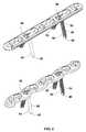
- FIG. 1is a top plan view of a serpentine plate configuration of a bone plate with a plurality of bi-directional screw holes, all in accordance with embodiments of the invention
- FIG. 2is a top plan view of a linear plate configuration of a bone plate with a plurality of bi-directional screw holes, all in accordance with embodiments of the invention
- FIG. 3depicts perspective views of the serpentine and linear bone plate configurations, illustrating both combination bi-directional holes and conventional holes;
- FIG. 4is a top view of serpentine plate configuration and a cross-sectional view, along plane A-A′, of the bi-directional divergent holes, illustrating the angled axes of the domains of each combination hole;
- FIG. 5is a perspective view of the directionality of individual screws when installed in bi-directional divergent holes
- FIG. 6is a perspective view of a by-pass locking screw in accordance with embodiments of the invention.
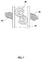
- FIG. 7is a top, cutaway view of a standard locking screw and a by-pass head screw, both positioned in the same bi-directional hole in accordance with embodiments of the invention.
- FIG. 8depicts perspective views of the serpentine and linear bone plate configurations, having only combination bi-directional holes.
- a bone fixation system embodying the principles illustrated in embodiments of the inventionis provided.
- the systemincludes a bone plate and a specialized screw system.
- bone screwrefers to a screw configured to be inserted into bone.
- the screwmay be threaded, or have a threaded portion, along its shaft, or may be non-threaded shaft, e.g., a non-threaded or smooth peg.
- the bone screwmay also be a locking screw with threads on the outer surface of its head.
- the head of the screwmay take several shapes from hemispherical to hexagonal recessed.
- combination holeor “combination aperture” is meant to refer a hole or aperture in a bone plate that is dimensioned and configured to have two portions or domains, each of which can accommodate a screw such that two screws can be positioned in the same combination hole.
- bi-directionalor “bi-angular” in reference to a combination hole or aperture is meant to refer to a hole or aperture in a bone plate that is dimensioned and configured to accommodate two screws wherein, when the screws are positioned in the same hole, the screws are directed at angles to each other and to the bone plate, i.e., the directions of the two screws in the same combination hole are non-parallel.
- by-pass headrefers to a specialized screw in accordance with embodiments of the invention in which the head of the screw has a substantially circular or spherical segment, i.e., the head is cut by a chord or plane.
- the by-pass head screwmay be locking or non-locking.
- a novel system and method for fixating bone fractures, especially long bone fracturesis provided.
- screw placementin case of fracture fixation with a plate, directed away from a plane perpendicular to the bottom surface of the plate is advantageous.
- a bi-angular or bidirectional combination screw hole configuration in a bone plateis provided which is in the form of at least one, and suitably a plurality of, such combination holes or apertures, each hole of which has two domains for holding and positioning screws.
- One domain of the holemay be suitably used to mate a conventional bone screw, e.g., a non-locking screw, in one direction away from the perpendicular or even along the perpendicular to the bottom surface of the plate, while the other domain of the same combination hole is suitably used to mate a screw, e.g., a locking screw, in an entirely different non-parallel direction.
- two screwsmay be suitably mated in each bi-angular hole wherein one screw is a conventional bone screw and the other is a by-pass head screw in accordance with embodiments of the invention.
- the direction of the screw placement per holedepends on the optimal configuration for individual fracture fixation and is not limited as in the existing prior art devices. It is also understood that the combination hole may accommodate two by-pass head screws as well.
- System 10includes a bone plate 20 and a screw system 21 for stabilizing bone segments.
- bone plate 20is defined by a first surface 22 and a second bone-contacting surface 24 that is opposed to the first surface 22 .
- Bone plate 20is suitably elongate, with a length 23 and a longitudinal axis 25 .
- Bone plate 20can optionally be curved along its length, enabling bone plate 20 to be anatomically contoured, i.e., to contour a bone surface.
- bone plate 20includes a plurality of combination screw apertures or holes 26 which extend through the first and second surfaces 22 , 24 of bone plate 20 .
- Each of the combination apertures or holes 26has a predefined shape and size.
- Each of the apertures or holes 26is suitably shaped as a bi-angular or an offset figure-eight, and is dimensioned and configured to receive a pair of screws 32 and 34 therethrough.
- Screws 32 , 34are used to anchor bone plate 20 to the particular bone segments that require fixation, i.e., are suitable for insertion into bone.
- Each hole 26has two domains 28 and 30 , respectively, which are substantially circular but overlapping, forming an offset figure-eight overall shape. Each domain is dimensioned and configured to receive one of the pair of screws therethrough. Domains 28 and 30 may or may not be provided with internal threads 41 . Internal threads 41 may engage the threads of a threaded head bone screw.
- one domain of a combination holehas a hole axis 36 and the other a hole axis is 38 .
- the axesare angled with respect to each other, i.e., the axes are non-parallel.
- screws 32 , 34have a head portion 36 and 38 , respectively, at a proximal end 42 .
- Each screw 32 , 34has an elongate body or shaft 44 that may include a threaded portion 46 , as shown in FIG. 5 , and/or a threaded head portion 45 .
- Such external threads 45 disposed along the screw headcan mately engage internal threads 41 of the domains of the bi-directional hole 26 . It is understood that non-threaded screws or pegs as well as conventional threaded head screws can also be accommodated in bidirectional holes 26 as shown in FIG. 5 .
- Bone plate 20may have many shapes.
- bone plate 20may have a suitably serpentine shape 52 with, e.g., an arched cross section contouring the bone surface.
- the serpentine shape coupled with the angled combination holespermit a materials-conserving plate configuration.
- the platecan be configured in many different shapes and sizes to accommodate any situation.
- FIG. 2illustrates another variation of the invention as a linear plate configuration 54
- FIGS. 3 and 8show perspective views of both the serpentine plate 52 and linear plate 54 .
- the embodiments of FIG. 3illustrate bone plate 20 with both combination bi-directional holes and conventional holes.
- the embodiments of FIG. 8illustrates bone plate 20 having only combination bi-directional holes.
- the underside of the bone platemay be concave, thus allowing the plate to conform to the rounded surface of the tibia, femur, humerus, forearm bone, and other bones with which embodiments of the invention may be used.
- the concave configuration of the undersidealso allows a conventional bone screw to be inserted obliquely through the plate hole when a small bone fragment must be gripped and pulled against the plate:
- a conventional head(e.g., substantially circular or hemispherical), bone screw 32 may be placed in at least one of the domains 28 , 30 of holes 26 and provide compression of the fractured bone fragments.
- screw 34has a by-pass head 50 .
- By-pass head 50 of screw 34allows two screws to be accommodated in the same single combination hole.
- a by-pass head screwmay be placed eccentrically with respect to the hole, as is necessary for attaining compression of a fracture.
- the second domain of hole 26may then receive the conventional full-head screw 32 , as such variation is shown in FIG. 7 .
- the second domain of the holeprovides an increased angulation of the bone screw with respect to the bone plate and the other screw. That two divergent screws are mated to the same bi-angular hole provides additional fixation to bone because screws, oriented divergently into the bone, offer significantly more resistance to pull out than any existing configuration. Torsional resistance is also theoretically greatly increased.
- FIGS. 4-7further illustrate embodiments of the invention with respect to the bi-directional screw holes and specialized by-pass screw head.
- one of the two screws mated into the bi-angular holecan be a conventional nonlocking screw which is capable of bringing the bone to the plate.
- the other screwcan then be mated to the plate and bone in a locking fashion.
- a surgeonhas to sacrifice several holes to bring the bone to the plate and then use the remaining holes in a “locking mode”.
- no holeis “wasted” and every hole could offer enhanced fixation beyond what an existing locking or non-locking screw can.
- a non-locking by-pass head screwcan be made to lock to the plate with a conventional locking screw that is mated to the adjacent domain of the same bi-angular screw.
- the bi-angular screw hole mated with two divergent screwsprovides added fixation in fractures adjacent to the softer bone proximate to joints, specifically, periarticular fractures and those that require articular subchondral support such as in distal radius fractures, tibial pilon fractures, tibial plateau fractures, etc.
- Bone plate 20may be provided with any number of holes 26 as may be suitable for a specific surgical application. Holes 26 may be disposed along the length 23 of bone plate 20 ; variations are illustrated, as shown, e.g., in FIGS. 1 and 2 .
- bone plate 20may be provided with other types and configurations of holes 40 , e.g., non-combination screw holes, in addition to combination holes 26 , as illustrated.
- bone plate 20may be provided with substantially cylindrical holes, threaded holes, or any other type of hole known to one of ordinary skill in the art.
- the threaded screwscan be self-tapping screws or pre-drilled with the aide of a drill guide. Additionally, the screws can be cannulated for insertion of a guide wire to guide screw placement.
- the screwsmay have a smooth shaft such as a peg.
- the hole domainsmay have a substantially conical shape with a doublelead thread.
- the length of the individual screw shaft and the shaft (threaded or smooth) configurationcan be selected for the particular application.
- the individual screw shaftcan also be smooth with a rounded, diamond, or trocar shaped tip.
- the domainsmay also be threaded or smooth, depending on whether the domain is accommodating a threaded screw or a peg.
- embodiments of the inventionprovide methods of fixating bone fractures.
- the methodincludes positioning a bone plate having, along its length, a plurality of bi-directional divergent holes therethrough to a fracture site, inserting bone screws through the bi-directional holes of the bone plate into a bone or bone fragments to fixate the fracture, the screws being oriented in the bone in non-parallel directions.
- the full mechanical advantage of the combination hole configuration in accordance with embodiments of the inventionis realized when two screws are mated to the same bi-directional or bi-angular hole.
- the head of one screw to be mated to the platesuitably has a by-pass head to allow the placement in the same hole of a second screw with a conventional full-headed screw. Having two fixed-angle screws oriented in divergent directions into the substance of the bone enhances the pull out strength of the plate from the bone far beyond that of a single locking screw oriented perpendicular to the plate.
Landscapes
- Health & Medical Sciences (AREA)
- Orthopedic Medicine & Surgery (AREA)
- Surgery (AREA)
- Life Sciences & Earth Sciences (AREA)
- Heart & Thoracic Surgery (AREA)
- Nuclear Medicine, Radiotherapy & Molecular Imaging (AREA)
- Engineering & Computer Science (AREA)
- Biomedical Technology (AREA)
- Neurology (AREA)
- Medical Informatics (AREA)
- Molecular Biology (AREA)
- Animal Behavior & Ethology (AREA)
- General Health & Medical Sciences (AREA)
- Public Health (AREA)
- Veterinary Medicine (AREA)
- Surgical Instruments (AREA)
Abstract
Description
The present application is a continuation of U.S. application Ser. No. 12/398,882, filed Mar. 5, 2009; which claims the benefit of U.S. Provisional Application No. 61/035,138, filed on Mar. 10, 2008; all of which are incorporated by reference herein.
1. Field of the Invention
The present invention relates to a system and method for bone fracture fixation.
2. Description of the Prior Art
Conventional bone fracture fixation plate and screw systems work by drawing the fracture fragments to the plate, and if designed with “compression” holes, the fracture fragments can be made to compress against each other to promote primary bone healing. However, the angular relationship between the plate and screws is not fixed and can change postoperatively. As such, this can lead to misalignment and poor clinical results.
One method of securing the screw to a bone plate involves the use of so-called “locking screws.” A locking screw has a male thread on an outer surface of its head that interfaces with a female thread on the plate to lock the screw to the plate. Bone plates having threaded holes for accommodating locking screws are known. For example, German Patent Application No. 43 43 117 discloses a bone plate with threaded holes for locking screws. As the relationship between the locking screws and the plate is fixed, locking screws provide a high resistance to shear or torsion forces. However, locking screws have a limited capability to compress bone fragments.
Another approach to construction of a bone plate involves use of “combination holes.” Combination holes in the bone plates have a domain for non-locking screws and another domain for locking screws. The locking screws can only be applied in a direction perpendicular to the plate. (See, e.g., U.S. Pat. Nos. 6,669,701 and 7,354,441 to Frigg) However, only a one locking or a non-locking screw can be applied in each of these “combination” holes along the bone plates.
Another bone plate hole configuration involves a “figure-eight” hole. (See, e.g., Universal Locking System available from Zimmer Holdings, Inc. (Warsaw, Ind.); see, also J. Bone and Joint Surgery, 89(7) 2007.) The figure-eight hole in the a bone plate has two parallel threaded domains. A locking screw can be mated to one domain of the holes or to the other domain of the same hole. In either case, the locking screw can be applied only perpendicular to the bone plate. Further, only one screw can be applied in each of these “figure-eight” holes along the plate.
In yet another approach, the bone plate has individual locking holes for mating individual locking screws. (See, e.g., MIS Technique available from Zimmer Holdings, Inc. (Warsaw, Ind.)) The individual holes are oriented alternating in one direction and in another direction (in the plane transverse to the longitudinal axis of the plate) away from the perpendicular to the plate. However, for such a configuration, half of the screw holes may not be suitable for use. In the worse case scenario, none of the holes can be used.
A system and method for bone fracture fixation, especially long bone fracture fixation, in acute injury or reconstruction setting is provided. The system includes a bone plate and a specialized screw system. The bone plate has an upper surface and an opposed lower surface, which contacts the bone to be fixated. The bone plate includes at least one, and suitably a plurality of bi-directional divergent combination holes, spaced apart along its length. Each bi-directional combination hole has two screw domains. The central axis of the domains are at angles to each other and in reference to the lower plate surface, i.e., the directions of the screws positioned in each domain of a combination hole are non-parallel. The specialized screw system includes a by-pass head screw having a cut away such that “by-pass” head of the screw allows placement of a “full head” screw immediately adjacent in the same combination hole. The screws may have a threaded portion along their shafts or may be non-threaded pegs. The specialized screws may be locking (i.e., threaded head) or non-locking.
In some embodiments, the invention provides a bone plate which has a suitably serpentine shape to optimize the use of materials around the bi-directional holes. The bi-directional holes may be disposed adjacent but offset or angled to one another, e.g., along the length of a bone plate. In other embodiments, the invention provides a bone plate, which has a suitably linear shape. The combination holes may also be placed adjacent to one another but are offset or angled with respect to each other and with respect to the longitudinal axis of the plate. The central axis of the domains of the combination holes are configured at an angle with respect to each other and with respect to the lower plate surface. The bone plate may include both combination and non-combination holes.
In another aspect, a method of fixating bone fractures is provided which includes positioning a bone plate having a plurality of bi-directional divergent holes therethrough to a fracture site, and inserting bone screws through the bi-directional holes of the bone plate into a bone or bone fragments to fixate the fracture, the screws being oriented in the bone in non-parallel directions. A by-pass head screw allows accommodation of a full head screw in the same hole.
Other advantages and a better appreciation of the specific adaptations, variations, and physical attributes of the invention will be gained upon an examination of the following detailed description of the invention, taken in conjunction with the accompanying drawings.
A bone fixation system embodying the principles illustrated in embodiments of the invention is provided. The system includes a bone plate and a specialized screw system.
Before any embodiments of the invention are explained in detail, it is to be understood that the invention is not limited in its application to the details of the structure and function set forth in the following description or illustrated in the appended drawings. The invention is capable of other embodiments and of being practiced or of being carried out in various ways.
Also, it is to be understood that the phraseology and terminology used herein is for the purpose of description and should not be regarded as limiting. The use of “comprising,” “including,” or “having” and variations thereof herein is meant to encompass the items listed thereafter and equivalents thereof as well as additional items. “Comprising” also encompasses the terms “consisting of” and “consisting essentially of” The use of “consisting essentially of” means, e.g., that a device may include additional features, but only if the additional features do not materially alter the basic and novel characteristics of the device.
Unless specified or limited otherwise, the terms “mounted,” “connected,” “supported,” and “coupled” and variations thereof are used broadly and encompass both direct and indirect mountings, connections, supports, and couplings. Further, “connected” and “coupled” are not restricted to physical or mechanical connections or couplings.
Further, no admission is made that any reference, including any patent or patent document, citied in this specification constitutes prior art. In particular, it will be understood that unless otherwise stated, reference to any document herein does not constitute an admission that any of these documents forms part of the common general knowledge in the art in the United States or in any other country. Any discussion of the references states what their authors assert, and applicant reserves the right to challenge the accuracy and pertinence of any of the documents cited herein.
As used in this specification and the appended claims, the singular forms “a,” “an,” and “the” include plural referents unless the content clearly dictates otherwise. As used in this specification and the appended claims, the term “or” is generally employed in its sense including “and/or” unless the content clearly dictates otherwise.
Unless otherwise noted, technical terms are used according to conventional usage. However, as used herein, the following definitions may be useful in aiding the skilled practitioner in understanding the invention. Such definitions shall be applied, unless a different definition is given in the claims or elsewhere in this specification.
The term “bone screw”, as used herein, refers to a screw configured to be inserted into bone. The screw may be threaded, or have a threaded portion, along its shaft, or may be non-threaded shaft, e.g., a non-threaded or smooth peg. The bone screw may also be a locking screw with threads on the outer surface of its head. The head of the screw may take several shapes from hemispherical to hexagonal recessed.
As used herein, the term “combination hole” or “combination aperture” is meant to refer a hole or aperture in a bone plate that is dimensioned and configured to have two portions or domains, each of which can accommodate a screw such that two screws can be positioned in the same combination hole.
As used herein, the term “bi-directional” or “bi-angular” in reference to a combination hole or aperture is meant to refer to a hole or aperture in a bone plate that is dimensioned and configured to accommodate two screws wherein, when the screws are positioned in the same hole, the screws are directed at angles to each other and to the bone plate, i.e., the directions of the two screws in the same combination hole are non-parallel.
The term “by-pass head” refers to a specialized screw in accordance with embodiments of the invention in which the head of the screw has a substantially circular or spherical segment, i.e., the head is cut by a chord or plane. The by-pass head screw may be locking or non-locking.
In view of the aforementioned disadvantages inherent in conventional bone fixation systems, a novel system and method for fixating bone fractures, especially long bone fractures, is provided. Given that many fractures have not only transverse fracture components but also oblique or, even rather frequently, long fracture lines along the bone, the inventor has been found that screw placement, in case of fracture fixation with a plate, directed away from a plane perpendicular to the bottom surface of the plate is advantageous. In one aspect, a bi-angular or bidirectional combination screw hole configuration in a bone plate is provided which is in the form of at least one, and suitably a plurality of, such combination holes or apertures, each hole of which has two domains for holding and positioning screws. One domain of the hole may be suitably used to mate a conventional bone screw, e.g., a non-locking screw, in one direction away from the perpendicular or even along the perpendicular to the bottom surface of the plate, while the other domain of the same combination hole is suitably used to mate a screw, e.g., a locking screw, in an entirely different non-parallel direction. In use, two screws may be suitably mated in each bi-angular hole wherein one screw is a conventional bone screw and the other is a by-pass head screw in accordance with embodiments of the invention. The direction of the screw placement per hole depends on the optimal configuration for individual fracture fixation and is not limited as in the existing prior art devices. It is also understood that the combination hole may accommodate two by-pass head screws as well.
Reference is now made toFIGS. 1-8 in which a bone fixation system, generally designated byreference numeral 10, in accordance with one embodiment of the invention is shown.System 10 includes abone plate 20 and ascrew system 21 for stabilizing bone segments. In one embodiment,bone plate 20 is defined by afirst surface 22 and a second bone-contactingsurface 24 that is opposed to thefirst surface 22.Bone plate 20 is suitably elongate, with alength 23 and alongitudinal axis 25.Bone plate 20 can optionally be curved along its length, enablingbone plate 20 to be anatomically contoured, i.e., to contour a bone surface.
In an illustrated embodiment,bone plate 20 includes a plurality of combination screw apertures or holes26 which extend through the first andsecond surfaces bone plate 20. Each of the combination apertures or holes26 has a predefined shape and size. Each of the apertures or holes26 is suitably shaped as a bi-angular or an offset figure-eight, and is dimensioned and configured to receive a pair ofscrews Screws bone plate 20 to the particular bone segments that require fixation, i.e., are suitable for insertion into bone. Eachhole 26 has twodomains Domains internal threads 41.Internal threads 41 may engage the threads of a threaded head bone screw.
Certain variations of the invention are set forth and illustrated in the figures. As shown inFIG. 4 , one domain of a combination hole has ahole axis 36 and the other a hole axis is38. The axes are angled with respect to each other, i.e., the axes are non-parallel. As shown inFIG. 7 , screws32,34 have ahead portion proximal end 42. Eachscrew shaft 44 that may include a threadedportion 46, as shown inFIG. 5 , and/or a threaded head portion45. Such external threads45 disposed along the screw head can mately engageinternal threads 41 of the domains of thebi-directional hole 26. It is understood that non-threaded screws or pegs as well as conventional threaded head screws can also be accommodated inbidirectional holes 26 as shown inFIG. 5 .
As described herein, in one variation, the underside of the bone plate may be concave, thus allowing the plate to conform to the rounded surface of the tibia, femur, humerus, forearm bone, and other bones with which embodiments of the invention may be used. The concave configuration of the underside also allows a conventional bone screw to be inserted obliquely through the plate hole when a small bone fragment must be gripped and pulled against the plate:
To accommodate two screws in a single combination hole, a conventional head, (e.g., substantially circular or hemispherical),bone screw 32 may be placed in at least one of thedomains holes 26 and provide compression of the fractured bone fragments. In the other domain, screw34 has a by-pass head 50. By-pass head 50 ofscrew 34 allows two screws to be accommodated in the same single combination hole.
For example, a by-pass head screw may be placed eccentrically with respect to the hole, as is necessary for attaining compression of a fracture. With the by-pass head screw in place in the first domain ofhole 26, the second domain ofhole 26 may then receive the conventional full-head screw 32, as such variation is shown inFIG. 7 . As described hereinabove, the second domain of the hole provides an increased angulation of the bone screw with respect to the bone plate and the other screw. That two divergent screws are mated to the same bi-angular hole provides additional fixation to bone because screws, oriented divergently into the bone, offer significantly more resistance to pull out than any existing configuration. Torsional resistance is also theoretically greatly increased.FIGS. 4-7 further illustrate embodiments of the invention with respect to the bi-directional screw holes and specialized by-pass screw head.
As noted, one of the two screws mated into the bi-angular hole can be a conventional nonlocking screw which is capable of bringing the bone to the plate. The other screw can then be mated to the plate and bone in a locking fashion. In current prior art devices, a surgeon has to sacrifice several holes to bring the bone to the plate and then use the remaining holes in a “locking mode”. In accordance with the invention, no hole is “wasted” and every hole could offer enhanced fixation beyond what an existing locking or non-locking screw can.
Similarly, a non-locking by-pass head screw can be made to lock to the plate with a conventional locking screw that is mated to the adjacent domain of the same bi-angular screw. The bi-angular screw hole mated with two divergent screws provides added fixation in fractures adjacent to the softer bone proximate to joints, specifically, periarticular fractures and those that require articular subchondral support such as in distal radius fractures, tibial pilon fractures, tibial plateau fractures, etc.
To facilitate insertion, the threaded screws can be self-tapping screws or pre-drilled with the aide of a drill guide. Additionally, the screws can be cannulated for insertion of a guide wire to guide screw placement. As noted, the screws may have a smooth shaft such as a peg. The hole domains may have a substantially conical shape with a doublelead thread. The length of the individual screw shaft and the shaft (threaded or smooth) configuration can be selected for the particular application. For example, the individual screw shaft can also be smooth with a rounded, diamond, or trocar shaped tip. The domains may also be threaded or smooth, depending on whether the domain is accommodating a threaded screw or a peg.
In practice, embodiments of the invention provide methods of fixating bone fractures. The method includes positioning a bone plate having, along its length, a plurality of bi-directional divergent holes therethrough to a fracture site, inserting bone screws through the bi-directional holes of the bone plate into a bone or bone fragments to fixate the fracture, the screws being oriented in the bone in non-parallel directions.
It should also be noted that during the surgical act of applying the plate to the fractured bone, critical vessels or nerves or muscle or other soft tissue may be in the way of the path of the intended drill hole. In accordance with embodiments of the invention, a surgeon is able to avoid undue retraction on the soft tissue or even minimize soft tissue dissection by choosing the more suitable direction afforded by the bi-directional hole design. Therefore, an additional benefit of the bi-directional design is its versatility, minimizing the requirement for soft tissue dissection and retraction.
In summary, the full mechanical advantage of the combination hole configuration in accordance with embodiments of the invention is realized when two screws are mated to the same bi-directional or bi-angular hole. The head of one screw to be mated to the plate suitably has a by-pass head to allow the placement in the same hole of a second screw with a conventional full-headed screw. Having two fixed-angle screws oriented in divergent directions into the substance of the bone enhances the pull out strength of the plate from the bone far beyond that of a single locking screw oriented perpendicular to the plate.
The foregoing description is considered as illustrative only of the principles manifest in embodiments of the invention. Further, since numerous modifications and changes may readily occur to those skilled in the art, it is not desired to limit the invention to the exact construction and operation shown and described, and accordingly, all suitable modifications and equivalents are considered to fall within the scope of the invention. Various features and advantages of the invention are set forth in the following claims.
All publications, patents and patent applications referenced in this specification are indicative of the level of ordinary skill in the art to which this invention pertains. All publications, patents and patent applications are herein expressly incorporated by reference to the same extent as if each individual publication or patent application was specifically and individually indicated by reference. In case of conflict between the present disclosure and the incorporated patents, publications and references, the present disclosure should control.
Other embodiments of the invention will be apparent to those skilled in the art from consideration of the specification and practice of the invention disclosed herein. It is intended that the specification and examples be considered as exemplary only, with a true scope and spirit of the invention being indicated by the following claims.
Claims (29)
1. A bone fixation system adapted to stabilize at least two bone portions of a fractured bone, the bone fixation system comprising:
a plate having a mid-longitudinal axis, a first end, a second end, a length between said first and second ends, and a width less than and perpendicular to said length, said length being sufficient to overlap the at least two bone portions, said plate having an upper surface, a lower surface, and a thickness between said upper and lower surfaces, said lower surface being opposite said upper surface, the mid-longitudinal axis extending through said first and second ends and along said length of said plate;
at least one bi-directional hole extending through said plate from said upper surface to said lower surface, said at least one bi-directional hole having a first bone fastener receiving portion, a second bone fastener receiving portion, and a connecting portion between said first and second bone fastener receiving portions, said first bone fastener receiving portion including a central longitudinal axis extending between said upper and lower surfaces, and said second bone fastener receiving portion including a central longitudinal axis extending between said upper and lower surfaces, the central longitudinal axes of said first and second bone fastener receiving portions diverging from one another below said lower surface of said plate, the central longitudinal axes of said first and second bone fastener receiving portions being transverse to a first plane extending along the mid-longitudinal axis of said plate and the first plane being perpendicular to said upper surface of said plate, and the central longitudinal axes of said first and second bone fastener receiving portions extending in second and third planes, respectively, said second and third planes being parallel to one another and crossing the mid-longitudinal axis at different points along said length of said plate, said first and second bone fastener receiving portions being threaded; and
at least two bone fasteners, each of said at least two bone fasteners including a head portion adapted to engage said plate and a shaft portion adapted to engage the fractured bone, a first bone fastener of said at least two bone fasteners being received and seated in said first bone fastener receiving portion and a second bone fastener of said at least two bone fasteners being received and seated in said second bone fastener receiving portion, said head portions having threads formed thereon, said threads of said head portions of said first and second bone fasteners being adapted to engage said threads of said first and second bone fastener receiving portions, respectively, one of said first and second bone fasteners including a cut-out portion formed on said head portion thereof, said cut-out portion interrupting said threads formed on said head portion of said one of said first and second bone fasteners, said first and second bone fasteners, when received in said first and second bone fastener receiving portions, respectively, being oriented at angles aligned with the central longitudinal axes of said respective first and second bone fastener receiving portions, and diverging from one another below said lower surface of said plate, wherein, when said one of said first and second bone fasteners is seated in one of said first and second bone fastener receiving portions, and said cut-out portion is oriented toward said connecting portion between said first and second bone fastener receiving portions, said cut-out portion allowing passage of said head portion of the other of said first and second bone fasteners into the other of said first and second bone fastener receiving portions, said head of said one of said first and second bone fasteners including said cut-out portion having a cross sectional configuration through said head such that if said cut-out portion is oriented away from said connecting portion between said first and second bone fastener receiving portions when seated in said one of said first and second bone fastener receiving portions, said cross sectional configuration of said head prevents passage of said head portion of the other of said first and second bone fasteners into the other of said first and second bone fastener receiving portions, said head portion of the other of said first and second bone fasteners directly abutting said cut-out portion of said one of said first and second bone fasteners.
2. The bone fixation system ofclaim 1 , wherein said head portion of the other of said first and second bone fasteners directly abutting said cut-out portion of said one of said first and second bone fasteners blocks rotation of said one of said first and second bone fasteners including said cut-out portion.
3. The bone fixation system ofclaim 1 , wherein said shaft portions of said first and second bone fasteners are at least partially threaded, said first and second bone fasteners being screws.
4. The bone fixation system ofclaim 3 , further comprising a tip included on each of said first and second bone screws, wherein said threads provided on each of said shaft portions are interrupted adjacent said tips.
5. The bone fixation system ofclaim 3 , further comprising a tip included on each of said first and second bone screws, said shafts of said first and second bone screws tapering toward said tips.
6. The bone fixation system ofclaim 1 , wherein at least a portion of said lower surface of said plate is concave.
7. The bone fixation system ofclaim 1 , wherein said first bone fastener receiving portion includes an arcuate portion at said upper surface extending around at least 180 degrees on a first side of the mid-longitudinal axis of said plate, and said second bone fastener receiving portion includes an arcuate portion at said upper surface extending around at least 180 degrees on a second side of the mid-longitudinal axis of said plate.
8. The bone fixation system ofclaim 7 , wherein said first bone fastener receiving portion includes a straight portion at said upper surface on the second side of the mid-longitudinal axis of said plate, and said second bone fastener receiving portion includes a straight portion at said upper surface on the first side of the mid-longitudinal axis of said plate, said straight portions of said first and second bone fastener receiving portions are substantially parallel to one another.
9. The bone fixation system ofclaim 1 , wherein said first and second bone fastener receiving portions communicate with one another via said connecting portion.
10. The bone fixation system ofclaim 1 , wherein the central longitudinal axes of said first and second bone fastener receiving portions is offset from one another along said length of said plate, and the central longitudinal axes of said first and second bone fastener receiving portions extending through said upper surface of said plate on opposite sides of the mid-longitudinal axis of said plate.
11. The bone fixation system ofclaim 1 , wherein said shaft portions of said first and second bone fasteners are fully threaded.
12. The bone fixation system ofclaim 1 , wherein said shaft portions of said first and second bone fasteners are unthreaded.
13. The bone fixation system ofclaim 1 , wherein said shaft portions of said first and second bone fasteners comprise cannulated shafts adapted for insertion over guide wires.
14. A bone fixation system adapted to stabilize at least two bone portions of a fractured bone, the bone fixation system comprising:
a plate having a mid-longitudinal axis, said plate having a first end, a second end, a length between said first and second ends, and a width less than and perpendicular to said length, said length being sufficient to overlap the at least two bone portions, said plate having an upper surface, a lower surface, and a thickness between said upper and lower surfaces, said lower surface being opposite said upper surface, the mid-longitudinal axis extending through said first and second ends and along said length of said plate;
at least one bi-directional hole extending through said plate from said upper surface to said lower surface, said at least one bi-directional hole having a first bone fastener receiving portion, a second bone fastener receiving portion, and a connecting portion between said first and second bone fastener receiving portions, said first bone fastener receiving portion including a central longitudinal axis extending between said upper and lower surfaces, and said second bone fastener receiving portion including a central longitudinal axis extending between said upper and lower surfaces, the central longitudinal axes of said first and second bone fastener receiving portions diverging from one another below said lower surface of said plate, the central longitudinal axes of said first and second bone fastener receiving portions being offset from one another along said length of said plate, and the central longitudinal axes of said first and second bone fastener receiving portions extending through said upper surface of said plate on opposite sides of the mid-longitudinal axis of said plate, said first and second bone fastener receiving portions being threaded; and
at least two bone fasteners, each of said at least two bone fasteners including a head portion adapted to engage said plate and a shaft portion adapted to engage the fractured bone, a first bone fastener of said at least two bone fasteners being received and seated in said first bone fastener receiving portion and a second bone fastener of said at least two bone fasteners being received and seated in said second bone fastener receiving portion, said head portions having threads formed thereon, said threads of said head portions of said first and second bone fasteners being adapted to engage said threads of said first and second bone fastener receiving portions, respectively, one of said first and second bone fasteners includes a cut-out portion formed on said head portion thereof, said cut-out portion interrupting said threads formed on said head portion of said one of said first and second bone fasteners, said first and second bone fasteners, when received in said first and second bone fastener receiving portions, respectively, being oriented at angles aligned with the central longitudinal axes of said respective first and second bone fastener receiving portions, and diverging from one another below said lower surface of said plate, wherein, when said one of said first and second bone fasteners is seated in one of said first and second bone fastener receiving portions, and said cut-out portion is oriented toward said connecting portion between said first and second bone fastener receiving portions, said cut-out portion allowing passage of said head portion of the other of said first and second bone fasteners into the other of said first and second bone fastener receiving portions, said head of said one of said first and second bone fasteners including said cut-out portion having a cross sectional configuration through said head such that if said cut-out portion is oriented away from said connecting portion between said first and second bone fastener receiving portions when seated in said one of said first and second bone fastener receiving portions, said cross sectional configuration of said head prevents passage of said head portion of the other of said first and second bone fasteners into the other of said first and second bone fastener receiving portions, said head portion of the other of said first and second bone fasteners directly abutting said cut-out portion of said one of said first and second bone fasteners.
15. The bone fixation system according toclaim 14 , wherein said head portion of the other of said first and second bone fasteners directly abutting said cut-out portion of said one of said first and second bone fasteners blocks rotation of said one of said first and second bone fasteners including said cut-out portion.
16. The bone fixation system according toclaim 14 , wherein at least a portion of said lower surface of said plate is concave.
17. The bone fixation system according toclaim 14 , wherein the mid-longitudinal axis of said plate delineates a first side and a second side, said first bone fastener receiving portion including a straight portion at said upper surface on said first side of the mid-longitudinal axis of said plate, and said second bone fastener receiving portion including a straight portion at said upper surface on said second side of the mid-longitudinal axis of said plate, said straight portions of said first and second bone fastener receiving portions being substantially parallel to one another.
18. The bone fixation system according toclaim 14 , wherein said first and second bone fastener receiving portions communicate with one another via said connecting portion.
19. The bone fixation system ofclaim 14 , wherein said shaft portions of said first and second bone fasteners are at least partially threaded.
20. The bone fixation system ofclaim 14 , wherein said shaft portions of said first and second bone fasteners are fully threaded.
21. The bone fixation system ofclaim 14 , wherein said shaft portions of said first and second bone fasteners are unthreaded.
22. The bone fixation system ofclaim 14 , wherein said shaft portions of said first and second bone fasteners comprise cannulated shafts adapted for insertion over guide wires.
23. A bone fixation system adapted to stabilize at least two bone portions of a fractured bone, the bone fixation system comprising:
a plate having a mid-longitudinal axis delineating a first side and a second side of said plate, said plate having a first end, a second end, a length between said first and second ends, and a width less than and perpendicular to said length, said length being sufficient to overlap the at least two bone portions, said plate having an upper surface, a lower surface, and a thickness between said upper and lower surfaces, said lower surface being opposite said upper surface, the mid-longitudinal axis extending through said first and second ends and along said length of said plate;
at least one bi-directional hole extending through said plate from said upper surface to said lower surface, said at least one bi-directional hole having a first bone fastener receiving portion being threaded, a second bone fastener receiving portion being threaded, and a connecting portion between said first and second bone fastener receiving portions, said first bone fastener receiving portion including a first central longitudinal axis extending between said upper and lower surfaces and a first radius measured from the first central longitudinal axis to a first side wall proximate said upper surface, and said second bone fastener receiving portion including a second central longitudinal axis extending between said upper and lower surfaces and a second radius measured from the second central longitudinal axis to a second side wall proximate said upper surface, said first bone fastener receiving portion including a first arcuate portion having a first arc of radius at said upper surface extending continuously around at least 180 degrees on said first side of the mid-longitudinal axis of said plate, said first arcuate portion of said first bone fastener receiving portion beginning on said second side of the mid-longitudinal axis, and said second bone fastener receiving portion including a second arcuate portion having a second arc of radius at said upper surface extending continuously around at least 180 degrees on said second side of the mid-longitudinal axis of said plate, said arcuate portion of said second bone fastener receiving portion beginning on said first side of the mid-longitudinal axis, the first arc of radius of said first arcuate portion intersecting the second arc of radius of said second arcuate portion, said first central longitudinal axis proximate said upper surface being spaced from said second central longitudinal axis proximate said upper surface a distance less than a combination of the first arc of radius and of the second arc of radius; and
at least two bone fasteners, each of said at least two bone fasteners including a head portion adapted to engage said plate and a shaft portion adapted to engage the fractured bone, a first bone fastener of said at least two bone fasteners being received and seated in said first bone fastener receiving portion and a second bone fastener of said at least two bone fasteners being received and seated in said second bone fastener receiving portion, said head portions having threads formed thereon, said threads of said head portions of said first and second bone fasteners being adapted to engage said threads of said first and second bone fastener receiving portions, respectively, a majority portion of said head of said first bone fastener being provided on said first side of the mid-longitudinal axis of said plate and another portion of said head of said first bone fastener being provided on said second side of said plate and said shaft portion of said first bone fastener being angled toward said second side of the mid-longitudinal axis of said plate, a majority portion of said second bone fastener being provided on said second side of said plate and another portion of said head of said second bone fastener being provided on said first side of said plate and said shaft portion of said second bone fastener being angled toward said first side of said plate, one of said first and second bone fasteners includes a cut-out portion formed on said head portion thereof, said cut-out portion interrupting said threads formed on said head portion of said one of said first and second bone fasteners, said first and second bone-fasteners, when received in said first and second bone fastener receiving portions, respectively, being oriented at angles aligned with the central longitudinal axis of said respective first and second bone fastener receiving portions, and diverging from one another below said lower surface of said plate, wherein, when said one of said first and second bone fasteners is seated in one of said first and second bone fastener receiving portions, and said cut-out portion is oriented toward said connecting portion between said first and second bone fastener receiving portions, said cut-out portion allowing passage of said head portion of the other of said first and second bone fasteners into the other of said first and second bone fastener receiving portions, said head portion of the other of said first and second bone fasteners directly abutting said cut-out portion of said one of said first and second bone fasteners so that said head portion of the other of said first and second bone fasteners blocks rotation of said one of said first and second bone fasteners including said cut-out portion.
24. The bone fixation system ofclaim 23 , wherein said shaft portions of said first and second bone fasteners being at least partially threaded.
25. The bone fixation system ofclaim 23 , wherein said shaft portions of said first and second bone fasteners are fully threaded.
26. The bone fixation system ofclaim 23 , wherein said shaft portions of said first and second bone fasteners are unthreaded.
27. The bone fixation system ofclaim 23 , wherein said shaft portions of said first and second bone fasteners comprise cannulated shafts adapted for insertion over guide wires.
28. A bone fixation system adapted to stabilize at least two bone portions of a fractured bone, the bone fixation system comprising:
a plate having a mid-longitudinal axis delineating a first side and a second side of said plate, said plate having a first end, a second end, a length between said first and second ends, and a width less than and perpendicular to said length, said length being sufficient to overlap the at least two bone portions, said plate having an upper surface, a lower surface, and a thickness between said upper and lower surfaces, said lower surface being opposite said upper surface, the mid-longitudinal axis extending through said first and second ends and along said length of said plate;
at least one bi-directional hole extending through said plate from said upper surface to said lower surface, said at least one bi-directional hole having a first bone fastener receiving portion being threaded, a second bone fastener receiving portion being threaded, and a connecting portion between said first and second bone fastener receiving portions, said first bone fastener receiving portion including a first central longitudinal axis extending between said upper and lower surfaces and a first radius measured from the first central longitudinal axis to a first side wall proximate said upper surface, and said second bone fastener receiving portion including a second central longitudinal axis extending between said upper and lower surfaces and a second radius measured from the second central longitudinal axis to a second side wall proximate said upper surface, a majority portion of said first bone fastener receiving portion being provided on said first side of said plate and another portion of said first bone fastener receiving portion being provided on said second side of said plate, a majority portion of said second bone fastener receiving portion being provided on said second side of said plate and another portion of said second bone fastener receiving portion being provided on said first side of said plate, said first and second bone fastener receiving portions communicating via said connecting portion, said connecting portion extending across the mid-longitudinal axis of said plate, and said connecting portion adapted to receive portions of at least two bone fasteners; and
at least two bone fasteners, each of said at least two bone fasteners including a head portion adapted to engage said plate and a shaft portion adapted to engage the fractured bone, a first bone fastener of said at least two bone fastener being received and seated in said first bone fastener receiving portion and a second bone fastener of said at least two bone fasteners being received and seated in said second bone fastener receiving portion, said head portions having threads formed thereon, said threads of said head portions of said first and second bone fasteners being adapted to engage said threads of said first and second bone fastener receiving portions, respectively, a majority portion of said head of said first bone fastener being provided on said first side of the mid-longitudinal axis of said plate and another portion of said head of said first bone fastener being provided on said second side of said plate and said shaft portion of said first bone fastener being angled toward said second side of the mid-longitudinal axis of said plate, a majority portion of said second bone fastener being provided on said second side of said plate and another portion of said head of said second bone fastener being provided on said first side of said plate and said shaft portion of said second bone fastener being angled toward said first side of said plate, one of said first and second bone fasteners includes a cut-out portion formed on said head portion thereof, said cut-out portion interrupting said threads formed on said head portion of said one of said first and second bone fasteners, said first and second bone-fasteners, when received in said first and second bone fastener receiving portions, respectively, being oriented at angles aligned with the central longitudinal axes of said respective first and second bone fastener receiving portions, and diverging from one another below said lower surface of said plate, wherein, when said one of said first and second bone fasteners is seated in one of said first and second bone fastener receiving portions, and said cut-out portion is oriented toward said connecting portion between said first and second bone fastener receiving portions, said cut-out portion allowing passage of said head portion of the other of said first and second bone fasteners into the other of said first and second bone fastener receiving portions, said head portion of the other of said first and second bone fasteners directly abutting said cut-out portion of said one of said first and second bone fasteners so that said head portion of the other of said first and second bone fasteners blocks rotation of said one of said first and second bone fasteners including said cut-out portion.
29. The bone fixation system ofclaim 28 , wherein said shaft portions of said first and second bone fasteners are at least partially threaded.
Priority Applications (1)
| Application Number | Priority Date | Filing Date | Title |
|---|---|---|---|
| US13/439,725US8764808B2 (en) | 2008-03-10 | 2012-04-04 | Bone fixation system |
Applications Claiming Priority (3)
| Application Number | Priority Date | Filing Date | Title |
|---|---|---|---|
| US3513808P | 2008-03-10 | 2008-03-10 | |
| US12/398,882US20090228010A1 (en) | 2008-03-10 | 2009-03-05 | Bone fixation system |
| US13/439,725US8764808B2 (en) | 2008-03-10 | 2012-04-04 | Bone fixation system |
Related Parent Applications (1)
| Application Number | Title | Priority Date | Filing Date |
|---|---|---|---|
| US12/398,882ContinuationUS20090228010A1 (en) | 2008-03-10 | 2009-03-05 | Bone fixation system |
Publications (2)
| Publication Number | Publication Date |
|---|---|
| US20120197308A1 US20120197308A1 (en) | 2012-08-02 |
| US8764808B2true US8764808B2 (en) | 2014-07-01 |
Family
ID=41054430
Family Applications (2)
| Application Number | Title | Priority Date | Filing Date |
|---|---|---|---|
| US12/398,882AbandonedUS20090228010A1 (en) | 2008-03-10 | 2009-03-05 | Bone fixation system |
| US13/439,725ActiveUS8764808B2 (en) | 2008-03-10 | 2012-04-04 | Bone fixation system |
Family Applications Before (1)
| Application Number | Title | Priority Date | Filing Date |
|---|---|---|---|
| US12/398,882AbandonedUS20090228010A1 (en) | 2008-03-10 | 2009-03-05 | Bone fixation system |
Country Status (4)
| Country | Link |
|---|---|
| US (2) | US20090228010A1 (en) |
| EP (1) | EP2252224A4 (en) |
| AU (1) | AU2009223517B2 (en) |
| WO (1) | WO2009114389A2 (en) |
Cited By (44)
| Publication number | Priority date | Publication date | Assignee | Title |
|---|---|---|---|---|
| US8870963B2 (en) | 2010-10-27 | 2014-10-28 | Toby Orthopaedics, Inc. | System and method for fracture replacement of comminuted bone fractures or portions thereof adjacent bone joints |
| US9254154B2 (en) | 2011-03-03 | 2016-02-09 | Toby Orthopaedic, Inc. | Anterior lesser tuberosity fixed angle fixation device and method of use associated therewith |
| US9271776B2 (en) | 2010-10-05 | 2016-03-01 | Toby Orthopaedics, Inc. | System and method for facilitating repair and reattachment of comminuted bone portions |
| US9271772B2 (en) | 2011-10-27 | 2016-03-01 | Toby Orthopaedics, Inc. | System and method for fracture replacement of comminuted bone fractures or portions thereof adjacent bone joints |
| US9283008B2 (en) | 2012-12-17 | 2016-03-15 | Toby Orthopaedics, Inc. | Bone plate for plate osteosynthesis and method for use thereof |
| US9333014B2 (en) | 2013-03-15 | 2016-05-10 | Eduardo Gonzalez-Hernandez | Bone fixation and reduction apparatus and method for fixation and reduction of a distal bone fracture and malunion |
| US9402667B2 (en) | 2011-11-09 | 2016-08-02 | Eduardo Gonzalez-Hernandez | Apparatus and method for use of the apparatus for fracture fixation of the distal humerus |
| US9730797B2 (en) | 2011-10-27 | 2017-08-15 | Toby Orthopaedics, Inc. | Bone joint replacement and repair assembly and method of repairing and replacing a bone joint |
| US20180271564A1 (en)* | 2015-12-01 | 2018-09-27 | Revivo Medical, Llc | Bone fixation apparatus with fastener securement mechanism and methods of use |
| US10368928B2 (en) | 2017-03-13 | 2019-08-06 | Globus Medical, Inc. | Bone stabilization systems |
| US10383668B2 (en) | 2016-08-17 | 2019-08-20 | Globus Medical, Inc. | Volar distal radius stabilization system |
| US10420596B2 (en) | 2016-08-17 | 2019-09-24 | Globus Medical, Inc. | Volar distal radius stabilization system |
| US10575884B2 (en) | 2016-08-17 | 2020-03-03 | Globus Medical, Inc. | Fracture plates, systems, and methods |
| US10631903B2 (en) | 2017-03-10 | 2020-04-28 | Globus Medical Inc. | Clavicle fixation system |
| US10687873B2 (en) | 2016-08-17 | 2020-06-23 | Globus Medical Inc. | Stabilization systems |
| US10687874B2 (en) | 2015-08-27 | 2020-06-23 | Globus Medical, Inc | Proximal humeral stabilization system |
| US10751098B2 (en) | 2016-08-17 | 2020-08-25 | Globus Medical Inc. | Stabilization systems |
| US10828074B2 (en) | 2015-11-20 | 2020-11-10 | Globus Medical, Inc. | Expandalbe intramedullary systems and methods of using the same |
| US10828075B2 (en) | 2015-09-25 | 2020-11-10 | Globus Medical Inc. | Bone fixation devices having a locking feature |
| US10856920B2 (en) | 2017-09-13 | 2020-12-08 | Globus Medical Inc. | Bone stabilization systems |
| US10905477B2 (en) | 2017-03-13 | 2021-02-02 | Globus Medical, Inc. | Bone stabilization systems |
| US11071570B2 (en) | 2018-03-02 | 2021-07-27 | Globus Medical, Inc. | Distal tibial plating system |
| US11076898B2 (en) | 2015-08-27 | 2021-08-03 | Globus Medical, Inc. | Proximal humeral stabilization system |
| US11096730B2 (en) | 2017-09-13 | 2021-08-24 | Globus Medical Inc. | Bone stabilization systems |
| US11129627B2 (en) | 2019-10-30 | 2021-09-28 | Globus Medical, Inc. | Method and apparatus for inserting a bone plate |
| US11141172B2 (en) | 2018-04-11 | 2021-10-12 | Globus Medical, Inc. | Method and apparatus for locking a drill guide in a polyaxial hole |
| US11141204B2 (en) | 2016-08-17 | 2021-10-12 | Globus Medical Inc. | Wrist stabilization systems |
| US11197682B2 (en) | 2015-08-27 | 2021-12-14 | Globus Medical, Inc. | Proximal humeral stabilization system |
| US11197704B2 (en) | 2016-04-19 | 2021-12-14 | Globus Medical, Inc. | Implantable compression screws |
| US11197701B2 (en) | 2016-08-17 | 2021-12-14 | Globus Medical, Inc. | Stabilization systems |
| US11202663B2 (en) | 2019-02-13 | 2021-12-21 | Globus Medical, Inc. | Proximal humeral stabilization systems and methods thereof |
| US11213327B2 (en) | 2016-08-17 | 2022-01-04 | Globus Medical, Inc. | Fracture plates, systems, and methods |
| US11224468B2 (en) | 2018-03-02 | 2022-01-18 | Globus Medical, Inc. | Distal tibial plating system |
| US11284920B2 (en) | 2016-03-02 | 2022-03-29 | Globus Medical Inc. | Fixators for bone stabilization and associated systems and methods |
| US11331128B2 (en) | 2016-08-17 | 2022-05-17 | Globus Medical Inc. | Distal radius stabilization system |
| US11432857B2 (en) | 2016-08-17 | 2022-09-06 | Globus Medical, Inc. | Stabilization systems |
| US11452551B2 (en)* | 2015-12-08 | 2022-09-27 | Arthrex, Inc. | Bone compression plate |
| US11723647B2 (en) | 2019-12-17 | 2023-08-15 | Globus Medical, Inc. | Syndesmosis fixation assembly |
| US20230338073A1 (en)* | 2022-04-26 | 2023-10-26 | Stryker European Operations Limited | Internal Brace Plate |
| US20240099748A1 (en)* | 2020-12-17 | 2024-03-28 | Dgt Medical Limited | A bone fixation device and system and method for using the device |
| US12042200B2 (en) | 2016-09-22 | 2024-07-23 | Globus Medical, Inc. | Systems and methods for intramedullary nail implantation |
| US12064150B2 (en) | 2022-01-19 | 2024-08-20 | Globus Medical Inc. | System and method for treating bone fractures |
| US12185995B2 (en) | 2019-10-09 | 2025-01-07 | Globus Medical, Inc. | Bone stabilization systems |
| US12279795B2 (en) | 2017-09-13 | 2025-04-22 | Globus Medical, Inc. | Bone stabilization systems |
Families Citing this family (17)
| Publication number | Priority date | Publication date | Assignee | Title |
|---|---|---|---|---|
| US8182485B1 (en) | 2003-11-21 | 2012-05-22 | Toby Orthopaedics, Llc | Fracture fixation system |
| US20090228010A1 (en) | 2008-03-10 | 2009-09-10 | Eduardo Gonzalez-Hernandez | Bone fixation system |
| US8728126B2 (en)* | 2008-03-10 | 2014-05-20 | Dennis L. Steffen | Bone fixation system and method |
| AU2008354730A1 (en) | 2008-04-17 | 2009-10-22 | Toby Orthopaedics, Inc. | Soft tissue attachment system and clip |
| EP2438870A1 (en)* | 2010-10-07 | 2012-04-11 | Instrumentaria d.d. | Orthopedic implant device and system |
| US8551095B2 (en)* | 2011-02-02 | 2013-10-08 | Bionet Manufacturing, LLC | Bone plate having combination locking and compression screw holes |
| US8709092B2 (en) | 2011-02-16 | 2014-04-29 | Genesis Medical Devices, LLC | Periprosthetic fracture management enhancements |
| WO2013036362A1 (en)* | 2011-09-06 | 2013-03-14 | Synthes Usa, Llc | Pancarpal arthrodesis bone plate |
| US9265542B2 (en)* | 2012-06-27 | 2016-02-23 | DePuy Synthes Products, Inc. | Variable angle bone fixation device |
| DE102012021034B4 (en)* | 2012-10-26 | 2021-12-16 | Mahe Medical Gmbh | Screw for osteosynthetic fixation at a variable angle |
| US9510880B2 (en) | 2013-08-13 | 2016-12-06 | Zimmer, Inc. | Polyaxial locking mechanism |
| US9468479B2 (en)* | 2013-09-06 | 2016-10-18 | Cardinal Health 247, Inc. | Bone plate |
| CN103610494A (en)* | 2013-12-13 | 2014-03-05 | 李照文 | Bone fracture plate with arc-shaped plate |
| CN104739496A (en)* | 2015-03-12 | 2015-07-01 | 创辉医疗器械江苏有限公司 | Fine-thread universal bone fracture plate |
| US20180221067A1 (en)* | 2015-08-06 | 2018-08-09 | Industrias Medicas Sampedro | Divergent, biplanar and segmental plate for bone fixation |
| EP3348218B1 (en)* | 2017-01-13 | 2022-11-16 | Globus Medical, Inc. | Stabilization systems |
| US11389209B2 (en)* | 2019-07-19 | 2022-07-19 | Medos International Sarl | Surgical plating systems, devices, and related methods |
Citations (198)
| Publication number | Priority date | Publication date | Assignee | Title |
|---|---|---|---|---|
| US1950799A (en) | 1933-04-15 | 1934-03-13 | Carl P Jones | Fracture appliance |
| US2500370A (en) | 1947-06-30 | 1950-03-14 | Mckibbin Genevieve | Repair of femur fracture |
| US2555291A (en) | 1945-11-09 | 1951-05-29 | Illinois Tool Works | Fastener unit |
| US2875663A (en) | 1954-07-01 | 1959-03-03 | Illinois Tool Works | Threadless stud adapted for insertion in keyhole slot |
| US3489143A (en) | 1967-12-15 | 1970-01-13 | William X Halloran | Convertible hip pin |
| US3552389A (en) | 1966-06-22 | 1971-01-05 | Synthes Ag | Osteosynthetic pressure plate construction |
| US3579831A (en) | 1969-03-05 | 1971-05-25 | Irving J Stevens | Bone implant |
| US3716050A (en) | 1971-02-11 | 1973-02-13 | F Johnston | Olecranon plate |
| US3791380A (en) | 1971-12-13 | 1974-02-12 | G Dawidowski | Method and apparatus of immobilizing a fractured femur |
| US3900025A (en) | 1974-04-24 | 1975-08-19 | Jr Walter P Barnes | Apparatus for distracting or compressing longitudinal bone segments |
| US4263904A (en) | 1978-02-10 | 1981-04-28 | Judet Robert L | Osteosynthesis devices |
| US4535768A (en) | 1981-08-26 | 1985-08-20 | South African Inventions Development Corporation | Set of surgical instruments |
| DE8628766U1 (en) | 1986-10-25 | 1986-12-11 | Mecron Medizinische Produkte Gmbh, 1000 Berlin | Bone plate |
| US4683878A (en) | 1985-04-29 | 1987-08-04 | Kirschner Medical Corporation | Osteosynthetic fixation plate |
| US4733654A (en) | 1986-05-29 | 1988-03-29 | Marino James F | Intramedullar nailing assembly |
| FR2606268A1 (en) | 1986-11-07 | 1988-05-13 | Landos Applic Orthopediques Fs | Device for osteosynthesis of the neck of the femur |
| US4776330A (en) | 1986-06-23 | 1988-10-11 | Pfizer Hospital Products Group, Inc. | Modular femoral fixation system |
| US4790302A (en) | 1986-06-17 | 1988-12-13 | Colwill John C | Method and apparatus for fixing bone fractures |
| US4794919A (en) | 1986-01-31 | 1989-01-03 | Nilsson John S | Fixating device |
| US4838264A (en) | 1987-08-18 | 1989-06-13 | Bremer Orthopedics, Inc. | Torque limiting device for use with bone penetrating pins |
| US4858602A (en) | 1985-12-06 | 1989-08-22 | Howmedica GmbH Werk Schonkirchen | Bone nail for the treatment of upper arm fractures |
| DE8907443U1 (en) | 1989-06-19 | 1989-09-14 | Aesculap AG, 7200 Tuttlingen | Intramedullary splint for a long bone |
| US4870957A (en) | 1988-12-27 | 1989-10-03 | Marlowe Goble E | Ligament anchor system |
| US5003969A (en) | 1990-02-21 | 1991-04-02 | Orthopedic Designs, Inc. | Fracture alignment device |
| US5015248A (en) | 1990-06-11 | 1991-05-14 | New York Society For The Relief Of The Ruptured & Crippled, Maintaining The Hospital For Special Surgery | Bone fracture fixation device |
| US5041113A (en)* | 1989-07-20 | 1991-08-20 | Lutz Biedermann | Stabilization member for stabilizing bones |
| US5180383A (en) | 1991-10-09 | 1993-01-19 | Haydon Frank A | Method and device for attaching artificial joint implants to the ends of bones |
| US5190544A (en) | 1986-06-23 | 1993-03-02 | Pfizer Hospital Products Group, Inc. | Modular femoral fixation system |
| FR2680673A1 (en) | 1991-08-26 | 1993-03-05 | Medical Op | Device for stabilisation of a spine, in particular of the human spine, by a posterior route |
| EP0551588A1 (en) | 1992-01-14 | 1993-07-21 | Howmedica GmbH | Intramedullary nail for treating fractures of the proximal femur |
| US5324291A (en) | 1992-12-21 | 1994-06-28 | Smith & Nephew Richards, Inc. | Bone section reattachment apparatus and method |
| US5356410A (en) | 1991-12-13 | 1994-10-18 | Dietmar Pennig | Adjuvant for osteosynthesis in the case of pertrochanteric fracture of the neck of the femur |
| US5364399A (en)* | 1993-02-05 | 1994-11-15 | Danek Medical, Inc. | Anterior cervical plating system |
| US5423860A (en) | 1993-05-28 | 1995-06-13 | American Cyanamid Company | Protective carrier for suture anchor |
| DE4343117A1 (en) | 1993-12-17 | 1995-06-22 | Wolter Dietmar | Bone fixation system for Osteosynthesis |
| US5437667A (en) | 1992-11-10 | 1995-08-01 | Innovative Orthopaedics, Manufacturing, Inc. | Dynamic external fixator for the wrist |
| US5443516A (en) | 1989-04-11 | 1995-08-22 | Albrektsson; Bjoern | Joint prosthesis |
| US5458654A (en) | 1993-07-14 | 1995-10-17 | Ao-Forschungsinstitut Davos | Screw-fixed femoral component for hip joint prosthesis |
| US5462547A (en) | 1991-05-30 | 1995-10-31 | Synthes (U.S.A.) | Trochanter stabilization device |
| US5472444A (en) | 1994-05-13 | 1995-12-05 | Acumed, Inc. | Humeral nail for fixation of proximal humeral fractures |
| US5505734A (en) | 1993-10-06 | 1996-04-09 | Gruppo Industriale Bioimpianti S.R.L. | Lockable intramedullary nail for the humerus |
| US5578035A (en) | 1995-05-16 | 1996-11-26 | Lin; Chih-I | Expandable bone marrow cavity fixation device |
| US5584835A (en) | 1993-10-18 | 1996-12-17 | Greenfield; Jon B. | Soft tissue to bone fixation device and method |
| US5586985A (en) | 1994-10-26 | 1996-12-24 | Regents Of The University Of Minnesota | Method and apparatus for fixation of distal radius fractures |
| US5601553A (en) | 1994-10-03 | 1997-02-11 | Synthes (U.S.A.) | Locking plate and bone screw |
| US5620449A (en) | 1994-07-28 | 1997-04-15 | Orthofix, S.R.L. | Mechanical system for blind nail-hole alignment of bone screws |
| US5658287A (en) | 1995-06-05 | 1997-08-19 | Gruppo Industriale Bioimpianti S.R.L. | Locked intramedullary nail, suitable in particular for fractures of the femur |
| US5665088A (en) | 1993-10-06 | 1997-09-09 | Smith & Nephew Richards Inc. | Bone section reattachment apparatus and method |
| US5674222A (en) | 1994-06-01 | 1997-10-07 | Synthes (U.S.A.) | Forked plate |
| US5676667A (en) | 1995-12-08 | 1997-10-14 | Hausman; Michael | Bone fixation apparatus and method |
| US5681311A (en)* | 1994-09-15 | 1997-10-28 | Smith & Nephew, Inc. | Osteosynthesis apparatus |
| US5709686A (en) | 1995-03-27 | 1998-01-20 | Synthes (U.S.A.) | Bone plate |
| US5749872A (en) | 1995-09-08 | 1998-05-12 | Ace Medical Company | Keyed/keyless barrel for bone plates |
| US5766174A (en) | 1995-09-26 | 1998-06-16 | Orthologic Corporation | Intramedullary bone fixation device |
| US5776194A (en) | 1996-04-25 | 1998-07-07 | Nuvana Medical Innovations, Llc | Intermedullary rod apparatus and methods of repairing proximal humerus fractures |
| US5779704A (en) | 1996-03-19 | 1998-07-14 | Kim; Andrew C. | Bi-directional universal dynamic compression device |
| US5785712A (en) | 1996-04-16 | 1998-07-28 | Terray Corporation | Reconstruction bone plate |
| US5840078A (en) | 1995-03-01 | 1998-11-24 | Yerys; Paul | Method and apparatus for mechanical attachment of soft tissue to bone tissue |
| US5868749A (en) | 1996-04-05 | 1999-02-09 | Reed; Thomas M. | Fixation devices |
| US5931839A (en) | 1995-01-27 | 1999-08-03 | Medoff; Robert J. | Pin plate for fixation of bone fractures |
| WO1999038448A1 (en) | 1998-01-31 | 1999-08-05 | Depuy International Limited | A fixation device for a bone fracture |
| US5976139A (en) | 1996-07-17 | 1999-11-02 | Bramlet; Dale G. | Surgical fastener assembly |
| US6030389A (en) | 1997-08-04 | 2000-02-29 | Spinal Concepts, Inc. | System and method for stabilizing the human spine with a bone plate |
| DE19857279A1 (en) | 1998-12-11 | 2000-06-15 | Onur Tarhan | Bone screw |
| US6096040A (en) | 1996-06-14 | 2000-08-01 | Depuy Ace Medical Company | Upper extremity bone plates |
| DE29907161U1 (en) | 1999-04-22 | 2000-08-24 | Wischhöfer, Edlef, Prof. Dr. Dr.med., 85092 Kösching | Blocking plate for osteosynthesis on the humerus |
| US6149653A (en) | 1997-09-05 | 2000-11-21 | Deslauriers; Richard J. | Self-retaining anchor track and method of making and using same |
| US6152927A (en)* | 1997-05-15 | 2000-11-28 | Sdgi Holdings, Inc. | Anterior cervical plating system |
| US6200330B1 (en) | 1998-11-23 | 2001-03-13 | Theodore V. Benderev | Systems for securing sutures, grafts and soft tissue to bone and periosteum |
| US6206881B1 (en) | 1995-09-06 | 2001-03-27 | Synthes (Usa) | Bone plate |
| USD443060S1 (en) | 2000-06-01 | 2001-05-29 | Bristol-Myers Squibb Company | Bone plate |
| US6270499B1 (en) | 1997-10-20 | 2001-08-07 | Synthes (U.S.A.) | Bone fixation device |
| EP1132052A2 (en) | 2000-03-10 | 2001-09-12 | Wright Medical Technology, Inc. | Bone plating system |
| US6302887B1 (en) | 1998-07-20 | 2001-10-16 | Joseph John Spranza | Hardware for high strength fastening of bone |
| USD449692S1 (en)* | 1998-02-11 | 2001-10-23 | Gary K. Michelson | Anterior cervical plate |
| US6331179B1 (en) | 2000-01-06 | 2001-12-18 | Spinal Concepts, Inc. | System and method for stabilizing the human spine with a bone plate |
| US6348052B1 (en) | 1996-07-16 | 2002-02-19 | Giacomo J. Sammarco | Internal fixation plate |
| US6358250B1 (en) | 2000-02-01 | 2002-03-19 | Hand Innovations, Inc. | Volar fixation system |
| US6364881B1 (en)* | 1997-07-30 | 2002-04-02 | Interpore Cross International | Longitudinally adjustable bone plates and method for use thereof |
| US6379359B1 (en) | 2000-05-05 | 2002-04-30 | University Of North Carolina At Chapel Hill | Percutaneous intrafocal plate system |
| US6398783B1 (en)* | 1997-02-11 | 2002-06-04 | Sulzer Spine-Tech Inc. | Multi-lock anterior cervical plate |
| US6406478B1 (en) | 2001-05-24 | 2002-06-18 | Robert W. H. Kuo | Bone reinforcement plate for use on the spine |
| US6409768B1 (en) | 2000-03-16 | 2002-06-25 | Slobodan Tepic | Screw anchored joint prosthesis |
| US6413259B1 (en) | 2000-12-14 | 2002-07-02 | Blackstone Medical, Inc | Bone plate assembly including a screw retaining member |
| US6440135B2 (en) | 2000-02-01 | 2002-08-27 | Hand Innovations, Inc. | Volar fixation system with articulating stabilization pegs |
| US6468278B1 (en) | 1997-11-14 | 2002-10-22 | Medos Medizintechnik Gmbh | Implant for the stabilization of a fracture |
| US6572620B1 (en) | 2001-11-16 | 2003-06-03 | Lew C. Schon | Modular, blade-rod, intramedullary fixation device |
| US20030135216A1 (en) | 2000-05-25 | 2003-07-17 | Sevrain Lionel C. | Anchoring system for fixing objects to bones |
| US20030135212A1 (en) | 2002-01-11 | 2003-07-17 | Y. Chow James C. | Rod and plate bone fixation device for persons with osteophorosis |
| US6620195B2 (en) | 2001-04-18 | 2003-09-16 | Medicinelodge, Inc. | Apparatus and method for attaching a graft ligament to a bone |
| US6623486B1 (en) | 1999-09-13 | 2003-09-23 | Synthes (U.S.A.) | bone plating system |
| US6663669B1 (en) | 1999-10-22 | 2003-12-16 | Mark A Reiley | Ankle replacement system |
| US6669701B2 (en) | 2000-01-27 | 2003-12-30 | Synthes (Usa) | Bone plate |
| US6706046B2 (en) | 2000-02-01 | 2004-03-16 | Hand Innovations, Inc. | Intramedullary fixation device for metaphyseal long bone fractures and methods of using the same |
| US6712820B2 (en) | 2000-02-01 | 2004-03-30 | Hand Innovations, Inc. | Fixation plate system for dorsal wrist fracture fixation |
| US6719759B2 (en) | 1999-03-09 | 2004-04-13 | Synthes Ag Chur | Bone plate |
| US6730090B2 (en) | 2000-02-01 | 2004-05-04 | Hand Innovations, Inc. | Fixation device for metaphyseal long bone fractures |
| US20040097939A1 (en) | 1998-02-06 | 2004-05-20 | Bonutti Peter M. | Apparatus and method for treating a fracture of a bone |
| US6776781B1 (en)* | 2000-09-28 | 2004-08-17 | Farihan Renno | Spinal-column buttress plate assembly and method for attachment |
| US20040193278A1 (en) | 2003-03-31 | 2004-09-30 | Maroney Brian J. | Articulating surface replacement prosthesis |
| EP1468655A2 (en) | 2003-03-26 | 2004-10-20 | Precimed S.A. | Locking bone plate |
| US20040210220A1 (en) | 2001-07-17 | 2004-10-21 | Alain Tornier | Osteosynthesis plate for the upper end of the arm bone |
| US20050004574A1 (en) | 2003-06-11 | 2005-01-06 | Helmut Muckter | Osteosynthesis plate or comparable implant plus ball socket |
| US20050021033A1 (en) | 2001-02-16 | 2005-01-27 | Claudius Zeiler | Implant plate, method and facility for the manufacture thereof |
| US20050038513A1 (en)* | 1999-05-05 | 2005-02-17 | Michelson Gary K. | Apparatus for inserting nested interbody spinal fusion implants |
| US6863671B1 (en)* | 1999-10-21 | 2005-03-08 | Storz Gmbh & Co. Kg | Biodegradable fixation element |
| US6866665B2 (en) | 2003-03-27 | 2005-03-15 | Hand Innovations, Llc | Bone fracture fixation system with subchondral and articular surface support |
| US20050085819A1 (en) | 2003-08-28 | 2005-04-21 | Ellis Thomas J. | Bone plates |
| US6916323B2 (en) | 2001-08-21 | 2005-07-12 | Depuy Products, Inc. | Method and apparatus for percutaneously securing a bone screw and a bone plate to a bone of a patient |
| US6945973B2 (en) | 2003-05-01 | 2005-09-20 | Nuvasive, Inc. | Slidable bone plate system |
| US20050240187A1 (en) | 2004-04-22 | 2005-10-27 | Huebner Randall J | Expanded fixation of bones |
| US20050261688A1 (en)* | 2004-05-11 | 2005-11-24 | Grady Mark P Jr | Bone plate |
| US20050267476A1 (en) | 2001-05-23 | 2005-12-01 | Alan Chervitz | Apparatus and method for orthopedic fixation |
| US20050288681A1 (en) | 2004-06-29 | 2005-12-29 | Conrad Klotz | Instrumentation for recording and replicating orthopaedic implant orientation |
| US20060015072A1 (en) | 2004-07-14 | 2006-01-19 | Medical Components, Inc. | Catheter hub clip |
| US20060015101A1 (en) | 2004-07-15 | 2006-01-19 | Wright Medical Technology, Inc. | Intramedullary fixation assembly and devices and methods for installing the same |
| US7001388B2 (en) | 2004-01-23 | 2006-02-21 | Hand Innovations, Llc | System for stabilization of fractures of convex articular bone surfaces including subchondral support structure |
| US7063701B2 (en) | 1999-05-05 | 2006-06-20 | Sdgi Holdings, Inc. | Screws of cortical bone having a trailing end configured to cooperatively engage an implant |
| US20060161156A1 (en) | 2002-05-30 | 2006-07-20 | Orbay Jorge L | Fracture fixation device |
| US20060217722A1 (en) | 2003-09-08 | 2006-09-28 | Christof Dutoit | Bone-fixation device |
| US20060235400A1 (en)* | 2003-08-26 | 2006-10-19 | Rolf Schneider | Bone plate |
| US20060241617A1 (en) | 2005-04-04 | 2006-10-26 | Ashley Holloway | Bone plate with suture loops |
| US20060264946A1 (en)* | 2003-03-26 | 2006-11-23 | Young Robert A | Locking bone plate |
| US20060264956A1 (en) | 2005-05-20 | 2006-11-23 | Orbay Jorge L | Methods and apparatus for bone fastener implantation |
| US20060264947A1 (en) | 2005-05-20 | 2006-11-23 | Orbay Jorge L | Bone fixation system |
| US20070005074A1 (en) | 2003-08-11 | 2007-01-04 | Chudik Steven C | Method of minimally invasive shoulder replacement surgery |
| US20070016205A1 (en) | 2003-10-30 | 2007-01-18 | Florian Beutter | Bone plate |
| USD536453S1 (en) | 2004-03-25 | 2007-02-06 | Precimed S.A. | Bone plate |
| US20070083207A1 (en)* | 2005-09-21 | 2007-04-12 | Tara Ziolo | Variable angle bone fixation assembly |
| US20070123880A1 (en) | 2005-10-25 | 2007-05-31 | Robert Medoff | Bone fixation device and method |
| US20070123885A1 (en) | 2003-09-30 | 2007-05-31 | X-Spine Systems, Inc. | Screw locking mechanism and method |
| US7229445B2 (en)* | 2004-06-21 | 2007-06-12 | Synthes (Usa) | Bone plate with bladed portion |
| US7235079B2 (en) | 2004-11-18 | 2007-06-26 | Acumed Llc | Composite bone fasteners |
| US20070162015A1 (en) | 1998-03-31 | 2007-07-12 | Zimmer Technology, Inc. | Orthopaedic bone plate |
| US20070167953A1 (en) | 2006-01-17 | 2007-07-19 | Stryker Trauma Gmbh | Targeting device for orthopedic implants |
| US20070233115A1 (en) | 2006-03-17 | 2007-10-04 | Robert Sixto | Bone Plate with Variable Torsional Stiffness at Fixed Angle Holes |
| US20070233114A1 (en) | 2005-10-14 | 2007-10-04 | Stryker Leibinger Gmbh & Co. Kg | Bone plate with at least two elongate holes and bone plate system |
| WO2008007194A2 (en) | 2006-07-07 | 2008-01-17 | Precimed, S.A. | Bone plate with complex, adjacent holes joined by a bend relief zone |
| WO2008007196A2 (en)* | 2006-07-07 | 2008-01-17 | Precimed, S.A. | Bone plate with complex, adjacent holes joined by a relief-space |
| US20080015593A1 (en) | 2005-03-24 | 2008-01-17 | Joachim Pfefferle | Bone plate |
| US20080045960A1 (en) | 2004-03-25 | 2008-02-21 | Bruecker Kenneth | Locking tpo plate and method of use |
| US20080140130A1 (en) | 2004-01-26 | 2008-06-12 | Chan Jason S | Highly-versatile variable-angle bone plate system |
| US20080154311A1 (en) | 2004-12-23 | 2008-06-26 | Hans Ulrich Staeubli | Bone Fixing Device |
| US20080161853A1 (en) | 2006-12-28 | 2008-07-03 | Depuy Spine, Inc. | Spine stabilization system with dynamic screw |
| US20080161860A1 (en) | 2005-12-23 | 2008-07-03 | Uwe Ahrens | Bone Plate |
| US20080221577A1 (en) | 2007-01-26 | 2008-09-11 | Ebi, Llc | Intramedullary implant with locking and compression devices |
| US20080234752A1 (en) | 2007-03-21 | 2008-09-25 | The University Of North Carolina At Chapel Hill | Surgical plate puller devices and methods for use with surgical bone screw/plate systems |
| US20080234749A1 (en) | 2007-01-26 | 2008-09-25 | Zimmer Technology, Inc. | Bone plate providing threaded locking head screw capture |
| US20080249572A1 (en) | 2004-06-02 | 2008-10-09 | Vineet Dev Tandon | Bone Plate |
| US20090012571A1 (en) | 2007-07-03 | 2009-01-08 | Pioneer Surgical Technology, Inc. | Bone Plate System |
| US20090024173A1 (en) | 2006-03-17 | 2009-01-22 | Reis Jr Geraldo Marins Dos | Bone Plate |
| US20090048681A1 (en) | 2005-12-05 | 2009-02-19 | Ioannis Vlachos | Hip Resurfacing Implant |
| US7500983B1 (en) | 2004-06-09 | 2009-03-10 | Biomet Sports Medicine, Llc | Apparatus for soft tissue attachment |
| US20090076554A1 (en) | 2007-07-19 | 2009-03-19 | Acumed Llc | Insertion tool for bone plates |
| US20090105838A1 (en) | 2005-05-27 | 2009-04-23 | Enrico Russo | Osteosynthesis Modular Prosthesis, Particularily for Humerus Osterosynthesis |
| US7563263B2 (en) | 2000-02-01 | 2009-07-21 | Depuy Products, Inc. | Intramedullary fixation device for metaphyseal long bone fractures |
| US20090192550A1 (en) | 2004-06-10 | 2009-07-30 | Ebi, L.P. | Bone plating system |
| US20090216270A1 (en) | 2008-02-27 | 2009-08-27 | Scott Humphrey | Fixable suture anchor plate and method for tendon-to-bone repair |
| US7582107B2 (en) | 2003-02-03 | 2009-09-01 | Integra Lifesciences Corporation | Compression screw apparatuses, systems and methods |
| US20090228010A1 (en) | 2008-03-10 | 2009-09-10 | Eduardo Gonzalez-Hernandez | Bone fixation system |
| US7591823B2 (en) | 2001-10-18 | 2009-09-22 | Lagwire, Llc | System and method for the fixation of bone fractures |
| US20090254089A1 (en) | 2001-10-18 | 2009-10-08 | Pogo Screw, Llc | Stabilization system and method for the fixation of bone fractures |
| US7604657B2 (en) | 2005-09-19 | 2009-10-20 | Depuy Products, Inc. | Bone fixation plate with complex suture anchor locations |
| US20090264936A1 (en) | 2008-04-17 | 2009-10-22 | Eduardo Gonzalez-Hernandez | Soft tissue attachment system and clip |
| US20090275991A1 (en) | 2008-05-05 | 2009-11-05 | Medoff Robert J | Contoured bone plate for fracture fixation having hook members and drill guide for same |
| US20090275987A1 (en) | 2008-05-02 | 2009-11-05 | Thomas James Graham | Bone plate extender and extension system for bone restoration and methods of use thereof |
| US20090281578A1 (en) | 2008-05-12 | 2009-11-12 | Spencer Edwin E | Proximal humeral fracture reduction and fixation device |
| US20090299369A1 (en) | 2008-06-02 | 2009-12-03 | Skeletal Dynamics Llc | Hybrid Orthopedic Implant |
| US20090312760A1 (en) | 2004-10-07 | 2009-12-17 | Zimmer, Inc. | Bone fracture fixation system |
| US20090312802A1 (en) | 2007-09-13 | 2009-12-17 | Dasilva Manuel | System for making a bone repair |
| US7637908B1 (en) | 2006-06-08 | 2009-12-29 | Eduardo Gonzalez-Hernandez | System and method for intramedullary subchondral support fixation of radial head fractures |
| US20090326591A1 (en) | 2008-01-29 | 2009-12-31 | Spencer Jr Edwin E | System and method to position and secure fractured bones |
| US7651517B2 (en) | 2002-12-31 | 2010-01-26 | Depuy Acromed, Inc. | Bone plate and resilient screw system allowing bi-directional assembly |
| US7655029B2 (en) | 2001-05-28 | 2010-02-02 | Synthes Usa, Llc | Bone plate |
| US20100030276A1 (en) | 2008-07-31 | 2010-02-04 | Dave Huebner | Periarticular Bone Plate With Biplanar Offset Head Member |
| US20100057086A1 (en) | 2008-08-29 | 2010-03-04 | Zimmer, Inc. | Anodized locking plate components |
| US20100145339A1 (en) | 2008-03-10 | 2010-06-10 | Steffen Dennis L | Bone fixation system and method |
| US7744638B2 (en) | 2004-01-23 | 2010-06-29 | Depuy Products, Inc. | System for stabilization of fractures of convex articular bone surfaces including subchondral support structure |
| US7780710B2 (en) | 2004-01-23 | 2010-08-24 | Depuy Products, Inc. | System for stabilization of fractures of convex articular bone surfaces including subchondral support structure |
| US7780667B2 (en) | 2003-09-08 | 2010-08-24 | Smith & Nephew, Inc. | Orthopaedic plate and screw assembly |
| US20100217393A1 (en) | 2009-02-20 | 2010-08-26 | Theofilos Charles S | Interbody fusion system with intervertebral implant retention assembly |
| US20100262194A1 (en) | 2007-11-13 | 2010-10-14 | Synthes Gmbh | Periprosthetic Fracture Repair |
| US20100274245A1 (en) | 2003-11-21 | 2010-10-28 | Eduardo Gonzalez-Hernandez | Fracture fixation system |
| US7896886B2 (en) | 2005-01-28 | 2011-03-01 | Depuy Products, Inc. | Nail plate and implantation jig therefor |
| US7909859B2 (en) | 2004-02-26 | 2011-03-22 | Pioneer Surgical Technology, Inc. | Bone plate system and methods |
| US7914532B2 (en) | 2005-10-21 | 2011-03-29 | Acumed Llc | Orthopedic rod with locking aperture |
| US7938850B2 (en) | 2002-05-30 | 2011-05-10 | Depuy Products, Inc. | Nail plate |
| US7951176B2 (en) | 2003-05-30 | 2011-05-31 | Synthes Usa, Llc | Bone plate |
| US7951178B2 (en) | 2006-04-03 | 2011-05-31 | Acumed Llc | Bone plates with hybrid apertures |
| US20110152943A1 (en) | 2009-12-22 | 2011-06-23 | Eduardo Gonzalez-Hernandez | Bone plate and tool assembly and method for use thereof |
| USD643121S1 (en) | 2010-05-27 | 2011-08-09 | Ebi, Llc | Orthopedic wrist spanning bone plate |
| USD646785S1 (en) | 2010-05-27 | 2011-10-11 | Ebi, Llc | Orthopedic volar bone plate |
| US20120083848A1 (en) | 2010-10-05 | 2012-04-05 | Eduardo Gonzalez-Hernandez | System and method for facilitating repair and reattachment of comminuted bone portions |
| US20120109322A1 (en) | 2010-10-27 | 2012-05-03 | Eduardo Gonzalez-Hernandez | System and method for fracture replacement of comminuted bone fractures or portions thereof adjacent bone joints |
| US20120226323A1 (en) | 2011-03-03 | 2012-09-06 | Eduardo Gonzalez-Hernandez | Anterior lesser tuberosity fixed angle fixation device and method of use associated therewith |
| US20120226322A1 (en) | 2011-03-04 | 2012-09-06 | Eduardo Gonzalez-Hernandez | Extra-medullary cortical buttress fixation device and method of use associated therewith |
| US20120226321A1 (en) | 2011-03-03 | 2012-09-06 | Eduardo Gonzalez-Hernandez | Modular and non-modular cortical buttress device |
| US20130116734A1 (en) | 2011-11-09 | 2013-05-09 | Eduardo Gonzalez-Hernandez | Apparatus and method for use of the apparatus for fracture fixation of the distal humerus |
Family Cites Families (1)
| Publication number | Priority date | Publication date | Assignee | Title |
|---|---|---|---|---|
| JP5743045B2 (en)* | 2008-07-16 | 2015-07-01 | ピーエスフォー ルクスコ エスエイアールエルPS4 Luxco S.a.r.l. | Semiconductor memory device and memory access method in semiconductor memory device |
- 2009
- 2009-03-05USUS12/398,882patent/US20090228010A1/ennot_activeAbandoned
- 2009-03-05EPEP09719181Apatent/EP2252224A4/ennot_activeWithdrawn
- 2009-03-05WOPCT/US2009/036211patent/WO2009114389A2/enactiveApplication Filing
- 2009-03-05AUAU2009223517Apatent/AU2009223517B2/ennot_activeCeased
- 2012
- 2012-04-04USUS13/439,725patent/US8764808B2/enactiveActive
Patent Citations (221)
| Publication number | Priority date | Publication date | Assignee | Title |
|---|---|---|---|---|
| US1950799A (en) | 1933-04-15 | 1934-03-13 | Carl P Jones | Fracture appliance |
| US2555291A (en) | 1945-11-09 | 1951-05-29 | Illinois Tool Works | Fastener unit |
| US2500370A (en) | 1947-06-30 | 1950-03-14 | Mckibbin Genevieve | Repair of femur fracture |
| US2875663A (en) | 1954-07-01 | 1959-03-03 | Illinois Tool Works | Threadless stud adapted for insertion in keyhole slot |
| US3552389A (en) | 1966-06-22 | 1971-01-05 | Synthes Ag | Osteosynthetic pressure plate construction |
| US3489143A (en) | 1967-12-15 | 1970-01-13 | William X Halloran | Convertible hip pin |
| US3579831A (en) | 1969-03-05 | 1971-05-25 | Irving J Stevens | Bone implant |
| US3716050A (en) | 1971-02-11 | 1973-02-13 | F Johnston | Olecranon plate |
| US3791380A (en) | 1971-12-13 | 1974-02-12 | G Dawidowski | Method and apparatus of immobilizing a fractured femur |
| US3900025A (en) | 1974-04-24 | 1975-08-19 | Jr Walter P Barnes | Apparatus for distracting or compressing longitudinal bone segments |
| US4263904A (en) | 1978-02-10 | 1981-04-28 | Judet Robert L | Osteosynthesis devices |
| US4535768A (en) | 1981-08-26 | 1985-08-20 | South African Inventions Development Corporation | Set of surgical instruments |
| US4683878A (en) | 1985-04-29 | 1987-08-04 | Kirschner Medical Corporation | Osteosynthetic fixation plate |
| US4858602A (en) | 1985-12-06 | 1989-08-22 | Howmedica GmbH Werk Schonkirchen | Bone nail for the treatment of upper arm fractures |
| US4794919A (en) | 1986-01-31 | 1989-01-03 | Nilsson John S | Fixating device |
| US4733654A (en) | 1986-05-29 | 1988-03-29 | Marino James F | Intramedullar nailing assembly |
| US4790302A (en) | 1986-06-17 | 1988-12-13 | Colwill John C | Method and apparatus for fixing bone fractures |
| US5041114A (en) | 1986-06-23 | 1991-08-20 | Pfizer Hospital Products Group, Inc. | Modular femoral fixation system |
| US4776330A (en) | 1986-06-23 | 1988-10-11 | Pfizer Hospital Products Group, Inc. | Modular femoral fixation system |
| US5190544A (en) | 1986-06-23 | 1993-03-02 | Pfizer Hospital Products Group, Inc. | Modular femoral fixation system |
| DE8628766U1 (en) | 1986-10-25 | 1986-12-11 | Mecron Medizinische Produkte Gmbh, 1000 Berlin | Bone plate |
| FR2606268A1 (en) | 1986-11-07 | 1988-05-13 | Landos Applic Orthopediques Fs | Device for osteosynthesis of the neck of the femur |
| US4838264A (en) | 1987-08-18 | 1989-06-13 | Bremer Orthopedics, Inc. | Torque limiting device for use with bone penetrating pins |
| US4870957A (en) | 1988-12-27 | 1989-10-03 | Marlowe Goble E | Ligament anchor system |
| US5443516A (en) | 1989-04-11 | 1995-08-22 | Albrektsson; Bjoern | Joint prosthesis |
| DE8907443U1 (en) | 1989-06-19 | 1989-09-14 | Aesculap AG, 7200 Tuttlingen | Intramedullary splint for a long bone |
| US5041113A (en)* | 1989-07-20 | 1991-08-20 | Lutz Biedermann | Stabilization member for stabilizing bones |
| US5003969A (en) | 1990-02-21 | 1991-04-02 | Orthopedic Designs, Inc. | Fracture alignment device |
| US5015248A (en) | 1990-06-11 | 1991-05-14 | New York Society For The Relief Of The Ruptured & Crippled, Maintaining The Hospital For Special Surgery | Bone fracture fixation device |
| US5462547A (en) | 1991-05-30 | 1995-10-31 | Synthes (U.S.A.) | Trochanter stabilization device |
| FR2680673A1 (en) | 1991-08-26 | 1993-03-05 | Medical Op | Device for stabilisation of a spine, in particular of the human spine, by a posterior route |
| US5180383A (en) | 1991-10-09 | 1993-01-19 | Haydon Frank A | Method and device for attaching artificial joint implants to the ends of bones |
| US5356410A (en) | 1991-12-13 | 1994-10-18 | Dietmar Pennig | Adjuvant for osteosynthesis in the case of pertrochanteric fracture of the neck of the femur |
| EP0551588A1 (en) | 1992-01-14 | 1993-07-21 | Howmedica GmbH | Intramedullary nail for treating fractures of the proximal femur |
| US5437667A (en) | 1992-11-10 | 1995-08-01 | Innovative Orthopaedics, Manufacturing, Inc. | Dynamic external fixator for the wrist |
| US5324291A (en) | 1992-12-21 | 1994-06-28 | Smith & Nephew Richards, Inc. | Bone section reattachment apparatus and method |
| US5364399A (en)* | 1993-02-05 | 1994-11-15 | Danek Medical, Inc. | Anterior cervical plating system |
| US5423860A (en) | 1993-05-28 | 1995-06-13 | American Cyanamid Company | Protective carrier for suture anchor |
| US5458654A (en) | 1993-07-14 | 1995-10-17 | Ao-Forschungsinstitut Davos | Screw-fixed femoral component for hip joint prosthesis |
| US5665088A (en) | 1993-10-06 | 1997-09-09 | Smith & Nephew Richards Inc. | Bone section reattachment apparatus and method |
| US5505734A (en) | 1993-10-06 | 1996-04-09 | Gruppo Industriale Bioimpianti S.R.L. | Lockable intramedullary nail for the humerus |
| US5584835A (en) | 1993-10-18 | 1996-12-17 | Greenfield; Jon B. | Soft tissue to bone fixation device and method |
| DE4343117A1 (en) | 1993-12-17 | 1995-06-22 | Wolter Dietmar | Bone fixation system for Osteosynthesis |
| US5472444A (en) | 1994-05-13 | 1995-12-05 | Acumed, Inc. | Humeral nail for fixation of proximal humeral fractures |
| US5674222A (en) | 1994-06-01 | 1997-10-07 | Synthes (U.S.A.) | Forked plate |
| US5620449A (en) | 1994-07-28 | 1997-04-15 | Orthofix, S.R.L. | Mechanical system for blind nail-hole alignment of bone screws |
| US5681311A (en)* | 1994-09-15 | 1997-10-28 | Smith & Nephew, Inc. | Osteosynthesis apparatus |
| US5601553A (en) | 1994-10-03 | 1997-02-11 | Synthes (U.S.A.) | Locking plate and bone screw |
| US5586985A (en) | 1994-10-26 | 1996-12-24 | Regents Of The University Of Minnesota | Method and apparatus for fixation of distal radius fractures |
| US5931839A (en) | 1995-01-27 | 1999-08-03 | Medoff; Robert J. | Pin plate for fixation of bone fractures |
| US5840078A (en) | 1995-03-01 | 1998-11-24 | Yerys; Paul | Method and apparatus for mechanical attachment of soft tissue to bone tissue |
| US5709686A (en) | 1995-03-27 | 1998-01-20 | Synthes (U.S.A.) | Bone plate |
| US5578035A (en) | 1995-05-16 | 1996-11-26 | Lin; Chih-I | Expandable bone marrow cavity fixation device |
| US5658287A (en) | 1995-06-05 | 1997-08-19 | Gruppo Industriale Bioimpianti S.R.L. | Locked intramedullary nail, suitable in particular for fractures of the femur |
| US6206881B1 (en) | 1995-09-06 | 2001-03-27 | Synthes (Usa) | Bone plate |
| US5749872A (en) | 1995-09-08 | 1998-05-12 | Ace Medical Company | Keyed/keyless barrel for bone plates |
| US5766174A (en) | 1995-09-26 | 1998-06-16 | Orthologic Corporation | Intramedullary bone fixation device |
| US5676667A (en) | 1995-12-08 | 1997-10-14 | Hausman; Michael | Bone fixation apparatus and method |
| US6695844B2 (en) | 1996-03-13 | 2004-02-24 | Orthopedic Designs, Inc. | Surgical fastener assembly |
| US5779704A (en) | 1996-03-19 | 1998-07-14 | Kim; Andrew C. | Bi-directional universal dynamic compression device |
| US5868749A (en) | 1996-04-05 | 1999-02-09 | Reed; Thomas M. | Fixation devices |
| US5785712A (en) | 1996-04-16 | 1998-07-28 | Terray Corporation | Reconstruction bone plate |
| US5776194A (en) | 1996-04-25 | 1998-07-07 | Nuvana Medical Innovations, Llc | Intermedullary rod apparatus and methods of repairing proximal humerus fractures |
| US6096040A (en) | 1996-06-14 | 2000-08-01 | Depuy Ace Medical Company | Upper extremity bone plates |
| US6348052B1 (en) | 1996-07-16 | 2002-02-19 | Giacomo J. Sammarco | Internal fixation plate |
| US5976139A (en) | 1996-07-17 | 1999-11-02 | Bramlet; Dale G. | Surgical fastener assembly |
| US6398783B1 (en)* | 1997-02-11 | 2002-06-04 | Sulzer Spine-Tech Inc. | Multi-lock anterior cervical plate |
| US6152927A (en)* | 1997-05-15 | 2000-11-28 | Sdgi Holdings, Inc. | Anterior cervical plating system |
| US6364881B1 (en)* | 1997-07-30 | 2002-04-02 | Interpore Cross International | Longitudinally adjustable bone plates and method for use thereof |
| US6030389A (en) | 1997-08-04 | 2000-02-29 | Spinal Concepts, Inc. | System and method for stabilizing the human spine with a bone plate |
| US6149653A (en) | 1997-09-05 | 2000-11-21 | Deslauriers; Richard J. | Self-retaining anchor track and method of making and using same |
| US6270499B1 (en) | 1997-10-20 | 2001-08-07 | Synthes (U.S.A.) | Bone fixation device |
| US6468278B1 (en) | 1997-11-14 | 2002-10-22 | Medos Medizintechnik Gmbh | Implant for the stabilization of a fracture |
| WO1999038448A1 (en) | 1998-01-31 | 1999-08-05 | Depuy International Limited | A fixation device for a bone fracture |
| US20040097939A1 (en) | 1998-02-06 | 2004-05-20 | Bonutti Peter M. | Apparatus and method for treating a fracture of a bone |
| USD449692S1 (en)* | 1998-02-11 | 2001-10-23 | Gary K. Michelson | Anterior cervical plate |
| US20070162015A1 (en) | 1998-03-31 | 2007-07-12 | Zimmer Technology, Inc. | Orthopaedic bone plate |
| US6302887B1 (en) | 1998-07-20 | 2001-10-16 | Joseph John Spranza | Hardware for high strength fastening of bone |
| US6200330B1 (en) | 1998-11-23 | 2001-03-13 | Theodore V. Benderev | Systems for securing sutures, grafts and soft tissue to bone and periosteum |
| DE19857279A1 (en) | 1998-12-11 | 2000-06-15 | Onur Tarhan | Bone screw |
| US6719759B2 (en) | 1999-03-09 | 2004-04-13 | Synthes Ag Chur | Bone plate |
| DE29907161U1 (en) | 1999-04-22 | 2000-08-24 | Wischhöfer, Edlef, Prof. Dr. Dr.med., 85092 Kösching | Blocking plate for osteosynthesis on the humerus |
| US7063701B2 (en) | 1999-05-05 | 2006-06-20 | Sdgi Holdings, Inc. | Screws of cortical bone having a trailing end configured to cooperatively engage an implant |
| US20050038513A1 (en)* | 1999-05-05 | 2005-02-17 | Michelson Gary K. | Apparatus for inserting nested interbody spinal fusion implants |
| US6623486B1 (en) | 1999-09-13 | 2003-09-23 | Synthes (U.S.A.) | bone plating system |
| US7128744B2 (en) | 1999-09-13 | 2006-10-31 | Synthes (Usa) | Bone plating system |
| US6863671B1 (en)* | 1999-10-21 | 2005-03-08 | Storz Gmbh & Co. Kg | Biodegradable fixation element |
| US6663669B1 (en) | 1999-10-22 | 2003-12-16 | Mark A Reiley | Ankle replacement system |
| US6331179B1 (en) | 2000-01-06 | 2001-12-18 | Spinal Concepts, Inc. | System and method for stabilizing the human spine with a bone plate |
| US6669701B2 (en) | 2000-01-27 | 2003-12-30 | Synthes (Usa) | Bone plate |
| US7354441B2 (en) | 2000-01-27 | 2008-04-08 | Synthes (U.S.A.) | Bone plate |
| US20080132955A1 (en) | 2000-01-27 | 2008-06-05 | Robert Frigg | Bone Plate |
| US6358250B1 (en) | 2000-02-01 | 2002-03-19 | Hand Innovations, Inc. | Volar fixation system |
| US6440135B2 (en) | 2000-02-01 | 2002-08-27 | Hand Innovations, Inc. | Volar fixation system with articulating stabilization pegs |
| US6706046B2 (en) | 2000-02-01 | 2004-03-16 | Hand Innovations, Inc. | Intramedullary fixation device for metaphyseal long bone fractures and methods of using the same |
| US6712820B2 (en) | 2000-02-01 | 2004-03-30 | Hand Innovations, Inc. | Fixation plate system for dorsal wrist fracture fixation |
| US6730090B2 (en) | 2000-02-01 | 2004-05-04 | Hand Innovations, Inc. | Fixation device for metaphyseal long bone fractures |
| US6364882B1 (en) | 2000-02-01 | 2002-04-02 | Hand Innovations, Inc. | Volar fixation system |
| US7563263B2 (en) | 2000-02-01 | 2009-07-21 | Depuy Products, Inc. | Intramedullary fixation device for metaphyseal long bone fractures |
| EP1132052A2 (en) | 2000-03-10 | 2001-09-12 | Wright Medical Technology, Inc. | Bone plating system |
| US6409768B1 (en) | 2000-03-16 | 2002-06-25 | Slobodan Tepic | Screw anchored joint prosthesis |
| US6379359B1 (en) | 2000-05-05 | 2002-04-30 | University Of North Carolina At Chapel Hill | Percutaneous intrafocal plate system |
| US20030135216A1 (en) | 2000-05-25 | 2003-07-17 | Sevrain Lionel C. | Anchoring system for fixing objects to bones |
| USD443060S1 (en) | 2000-06-01 | 2001-05-29 | Bristol-Myers Squibb Company | Bone plate |
| US6776781B1 (en)* | 2000-09-28 | 2004-08-17 | Farihan Renno | Spinal-column buttress plate assembly and method for attachment |
| US6413259B1 (en) | 2000-12-14 | 2002-07-02 | Blackstone Medical, Inc | Bone plate assembly including a screw retaining member |
| US20050021033A1 (en) | 2001-02-16 | 2005-01-27 | Claudius Zeiler | Implant plate, method and facility for the manufacture thereof |
| US6620195B2 (en) | 2001-04-18 | 2003-09-16 | Medicinelodge, Inc. | Apparatus and method for attaching a graft ligament to a bone |
| US20050267476A1 (en) | 2001-05-23 | 2005-12-01 | Alan Chervitz | Apparatus and method for orthopedic fixation |
| US6406478B1 (en) | 2001-05-24 | 2002-06-18 | Robert W. H. Kuo | Bone reinforcement plate for use on the spine |
| US7655029B2 (en) | 2001-05-28 | 2010-02-02 | Synthes Usa, Llc | Bone plate |
| US20040210220A1 (en) | 2001-07-17 | 2004-10-21 | Alain Tornier | Osteosynthesis plate for the upper end of the arm bone |
| US6916323B2 (en) | 2001-08-21 | 2005-07-12 | Depuy Products, Inc. | Method and apparatus for percutaneously securing a bone screw and a bone plate to a bone of a patient |
| US20090254089A1 (en) | 2001-10-18 | 2009-10-08 | Pogo Screw, Llc | Stabilization system and method for the fixation of bone fractures |
| US7591823B2 (en) | 2001-10-18 | 2009-09-22 | Lagwire, Llc | System and method for the fixation of bone fractures |
| US6572620B1 (en) | 2001-11-16 | 2003-06-03 | Lew C. Schon | Modular, blade-rod, intramedullary fixation device |
| US20030135212A1 (en) | 2002-01-11 | 2003-07-17 | Y. Chow James C. | Rod and plate bone fixation device for persons with osteophorosis |
| US20060161156A1 (en) | 2002-05-30 | 2006-07-20 | Orbay Jorge L | Fracture fixation device |
| US7938850B2 (en) | 2002-05-30 | 2011-05-10 | Depuy Products, Inc. | Nail plate |
| US7651517B2 (en) | 2002-12-31 | 2010-01-26 | Depuy Acromed, Inc. | Bone plate and resilient screw system allowing bi-directional assembly |
| US7582107B2 (en) | 2003-02-03 | 2009-09-01 | Integra Lifesciences Corporation | Compression screw apparatuses, systems and methods |
| US7722653B2 (en) | 2003-03-26 | 2010-05-25 | Greatbatch Medical S.A. | Locking bone plate |
| US20060264946A1 (en)* | 2003-03-26 | 2006-11-23 | Young Robert A | Locking bone plate |
| US7695472B2 (en) | 2003-03-26 | 2010-04-13 | Swiss Orthopedic Solutions Sa | Locking bone plate |
| US20050015089A1 (en)* | 2003-03-26 | 2005-01-20 | Young Robert Allan | Locking bone plate |
| EP1468655A2 (en) | 2003-03-26 | 2004-10-20 | Precimed S.A. | Locking bone plate |
| US7740648B2 (en) | 2003-03-26 | 2010-06-22 | Greatbatch Medical S.A. | Locking bone plate |
| US6866665B2 (en) | 2003-03-27 | 2005-03-15 | Hand Innovations, Llc | Bone fracture fixation system with subchondral and articular surface support |
| US20040193278A1 (en) | 2003-03-31 | 2004-09-30 | Maroney Brian J. | Articulating surface replacement prosthesis |
| US6945973B2 (en) | 2003-05-01 | 2005-09-20 | Nuvasive, Inc. | Slidable bone plate system |
| US7951176B2 (en) | 2003-05-30 | 2011-05-31 | Synthes Usa, Llc | Bone plate |
| US20050004574A1 (en) | 2003-06-11 | 2005-01-06 | Helmut Muckter | Osteosynthesis plate or comparable implant plus ball socket |
| US20070005074A1 (en) | 2003-08-11 | 2007-01-04 | Chudik Steven C | Method of minimally invasive shoulder replacement surgery |
| US20060235400A1 (en)* | 2003-08-26 | 2006-10-19 | Rolf Schneider | Bone plate |
| US20100331844A1 (en) | 2003-08-28 | 2010-12-30 | Ellis Thomas J | Bone fixation system |
| US20050085819A1 (en) | 2003-08-28 | 2005-04-21 | Ellis Thomas J. | Bone plates |
| US20060217722A1 (en) | 2003-09-08 | 2006-09-28 | Christof Dutoit | Bone-fixation device |
| US7780667B2 (en) | 2003-09-08 | 2010-08-24 | Smith & Nephew, Inc. | Orthopaedic plate and screw assembly |
| US20070123885A1 (en) | 2003-09-30 | 2007-05-31 | X-Spine Systems, Inc. | Screw locking mechanism and method |
| US8062367B2 (en)* | 2003-09-30 | 2011-11-22 | X-Spine Systems, Inc. | Screw locking mechanism and method |
| US20070016205A1 (en) | 2003-10-30 | 2007-01-18 | Florian Beutter | Bone plate |
| US8182485B1 (en) | 2003-11-21 | 2012-05-22 | Toby Orthopaedics, Llc | Fracture fixation system |
| US8574234B2 (en) | 2003-11-21 | 2013-11-05 | Toby Orthopaedics, Inc. | Fracture fixation system |
| US20100274245A1 (en) | 2003-11-21 | 2010-10-28 | Eduardo Gonzalez-Hernandez | Fracture fixation system |
| US7744638B2 (en) | 2004-01-23 | 2010-06-29 | Depuy Products, Inc. | System for stabilization of fractures of convex articular bone surfaces including subchondral support structure |
| US7001388B2 (en) | 2004-01-23 | 2006-02-21 | Hand Innovations, Llc | System for stabilization of fractures of convex articular bone surfaces including subchondral support structure |
| US7780710B2 (en) | 2004-01-23 | 2010-08-24 | Depuy Products, Inc. | System for stabilization of fractures of convex articular bone surfaces including subchondral support structure |
| US20080140130A1 (en) | 2004-01-26 | 2008-06-12 | Chan Jason S | Highly-versatile variable-angle bone plate system |
| US7909859B2 (en) | 2004-02-26 | 2011-03-22 | Pioneer Surgical Technology, Inc. | Bone plate system and methods |
| US20080045960A1 (en) | 2004-03-25 | 2008-02-21 | Bruecker Kenneth | Locking tpo plate and method of use |
| USD536453S1 (en) | 2004-03-25 | 2007-02-06 | Precimed S.A. | Bone plate |
| US20050240187A1 (en) | 2004-04-22 | 2005-10-27 | Huebner Randall J | Expanded fixation of bones |
| US20100324602A1 (en) | 2004-04-22 | 2010-12-23 | Acumed Llc | Expanded fixation of bones |
| US7776076B2 (en) | 2004-05-11 | 2010-08-17 | Synthes Usa, Llc | Bone plate |
| US20050261688A1 (en)* | 2004-05-11 | 2005-11-24 | Grady Mark P Jr | Bone plate |
| US20080249572A1 (en) | 2004-06-02 | 2008-10-09 | Vineet Dev Tandon | Bone Plate |
| US7500983B1 (en) | 2004-06-09 | 2009-03-10 | Biomet Sports Medicine, Llc | Apparatus for soft tissue attachment |
| US20090192550A1 (en) | 2004-06-10 | 2009-07-30 | Ebi, L.P. | Bone plating system |
| US7229445B2 (en)* | 2004-06-21 | 2007-06-12 | Synthes (Usa) | Bone plate with bladed portion |
| US20050288681A1 (en) | 2004-06-29 | 2005-12-29 | Conrad Klotz | Instrumentation for recording and replicating orthopaedic implant orientation |
| US7220246B2 (en) | 2004-07-14 | 2007-05-22 | Medical Components, Inc. | Catheter hub clip |
| US20060015072A1 (en) | 2004-07-14 | 2006-01-19 | Medical Components, Inc. | Catheter hub clip |
| US20060015101A1 (en) | 2004-07-15 | 2006-01-19 | Wright Medical Technology, Inc. | Intramedullary fixation assembly and devices and methods for installing the same |
| US20090312760A1 (en) | 2004-10-07 | 2009-12-17 | Zimmer, Inc. | Bone fracture fixation system |
| US7235079B2 (en) | 2004-11-18 | 2007-06-26 | Acumed Llc | Composite bone fasteners |
| US20080154311A1 (en) | 2004-12-23 | 2008-06-26 | Hans Ulrich Staeubli | Bone Fixing Device |
| US7896886B2 (en) | 2005-01-28 | 2011-03-01 | Depuy Products, Inc. | Nail plate and implantation jig therefor |
| US7927341B2 (en) | 2005-01-28 | 2011-04-19 | Depuy Products, Inc. | Nail plate and jig therefor |
| US20080015593A1 (en) | 2005-03-24 | 2008-01-17 | Joachim Pfefferle | Bone plate |
| US20060241617A1 (en) | 2005-04-04 | 2006-10-26 | Ashley Holloway | Bone plate with suture loops |
| US20060264947A1 (en) | 2005-05-20 | 2006-11-23 | Orbay Jorge L | Bone fixation system |
| US20060264956A1 (en) | 2005-05-20 | 2006-11-23 | Orbay Jorge L | Methods and apparatus for bone fastener implantation |
| US20090105838A1 (en) | 2005-05-27 | 2009-04-23 | Enrico Russo | Osteosynthesis Modular Prosthesis, Particularily for Humerus Osterosynthesis |
| US7604657B2 (en) | 2005-09-19 | 2009-10-20 | Depuy Products, Inc. | Bone fixation plate with complex suture anchor locations |
| US20070083207A1 (en)* | 2005-09-21 | 2007-04-12 | Tara Ziolo | Variable angle bone fixation assembly |
| US20070233114A1 (en) | 2005-10-14 | 2007-10-04 | Stryker Leibinger Gmbh & Co. Kg | Bone plate with at least two elongate holes and bone plate system |
| US7914532B2 (en) | 2005-10-21 | 2011-03-29 | Acumed Llc | Orthopedic rod with locking aperture |
| US20070123880A1 (en) | 2005-10-25 | 2007-05-31 | Robert Medoff | Bone fixation device and method |
| US20090048681A1 (en) | 2005-12-05 | 2009-02-19 | Ioannis Vlachos | Hip Resurfacing Implant |
| US20080161860A1 (en) | 2005-12-23 | 2008-07-03 | Uwe Ahrens | Bone Plate |
| US20070167953A1 (en) | 2006-01-17 | 2007-07-19 | Stryker Trauma Gmbh | Targeting device for orthopedic implants |
| US20090024173A1 (en) | 2006-03-17 | 2009-01-22 | Reis Jr Geraldo Marins Dos | Bone Plate |
| US20070233115A1 (en) | 2006-03-17 | 2007-10-04 | Robert Sixto | Bone Plate with Variable Torsional Stiffness at Fixed Angle Holes |
| US7951178B2 (en) | 2006-04-03 | 2011-05-31 | Acumed Llc | Bone plates with hybrid apertures |
| US7637908B1 (en) | 2006-06-08 | 2009-12-29 | Eduardo Gonzalez-Hernandez | System and method for intramedullary subchondral support fixation of radial head fractures |
| US20090171399A1 (en)* | 2006-07-07 | 2009-07-02 | Precimed, S.A. | Bone Plate with Complex, Adjacent Holes Joined by a Relief-Space |
| US8100953B2 (en) | 2006-07-07 | 2012-01-24 | Swiss Pro Orthpedic SA | Bone plate with complex, adjacent holes joined by a relief-space |
| WO2008007196A2 (en)* | 2006-07-07 | 2008-01-17 | Precimed, S.A. | Bone plate with complex, adjacent holes joined by a relief-space |
| WO2008007194A2 (en) | 2006-07-07 | 2008-01-17 | Precimed, S.A. | Bone plate with complex, adjacent holes joined by a bend relief zone |
| US20080161853A1 (en) | 2006-12-28 | 2008-07-03 | Depuy Spine, Inc. | Spine stabilization system with dynamic screw |
| US20080161863A1 (en) | 2006-12-28 | 2008-07-03 | Depuy Spine, Inc. | Spinal anchoring screw |
| US20080234749A1 (en) | 2007-01-26 | 2008-09-25 | Zimmer Technology, Inc. | Bone plate providing threaded locking head screw capture |
| US20080221577A1 (en) | 2007-01-26 | 2008-09-11 | Ebi, Llc | Intramedullary implant with locking and compression devices |
| US20080234752A1 (en) | 2007-03-21 | 2008-09-25 | The University Of North Carolina At Chapel Hill | Surgical plate puller devices and methods for use with surgical bone screw/plate systems |
| US20090012571A1 (en) | 2007-07-03 | 2009-01-08 | Pioneer Surgical Technology, Inc. | Bone Plate System |
| US20090076554A1 (en) | 2007-07-19 | 2009-03-19 | Acumed Llc | Insertion tool for bone plates |
| US20090312802A1 (en) | 2007-09-13 | 2009-12-17 | Dasilva Manuel | System for making a bone repair |
| US20100262194A1 (en) | 2007-11-13 | 2010-10-14 | Synthes Gmbh | Periprosthetic Fracture Repair |
| US20090326591A1 (en) | 2008-01-29 | 2009-12-31 | Spencer Jr Edwin E | System and method to position and secure fractured bones |
| US20090216270A1 (en) | 2008-02-27 | 2009-08-27 | Scott Humphrey | Fixable suture anchor plate and method for tendon-to-bone repair |
| US20090228010A1 (en) | 2008-03-10 | 2009-09-10 | Eduardo Gonzalez-Hernandez | Bone fixation system |
| US20100145339A1 (en) | 2008-03-10 | 2010-06-10 | Steffen Dennis L | Bone fixation system and method |
| US20120197305A1 (en) | 2008-04-17 | 2012-08-02 | Eduardo Gonzalez-Hernandez | Soft tissue attachment system and clip |
| US20090264936A1 (en) | 2008-04-17 | 2009-10-22 | Eduardo Gonzalez-Hernandez | Soft tissue attachment system and clip |
| US20130289627A1 (en) | 2008-04-17 | 2013-10-31 | Eduardo Gonzalez-Hernandez | Soft tissue attachment system and clip |
| US20090275987A1 (en) | 2008-05-02 | 2009-11-05 | Thomas James Graham | Bone plate extender and extension system for bone restoration and methods of use thereof |
| US20090275991A1 (en) | 2008-05-05 | 2009-11-05 | Medoff Robert J | Contoured bone plate for fracture fixation having hook members and drill guide for same |
| US20090281578A1 (en) | 2008-05-12 | 2009-11-12 | Spencer Edwin E | Proximal humeral fracture reduction and fixation device |
| US20090299369A1 (en) | 2008-06-02 | 2009-12-03 | Skeletal Dynamics Llc | Hybrid Orthopedic Implant |
| US20100030276A1 (en) | 2008-07-31 | 2010-02-04 | Dave Huebner | Periarticular Bone Plate With Biplanar Offset Head Member |
| US20100057086A1 (en) | 2008-08-29 | 2010-03-04 | Zimmer, Inc. | Anodized locking plate components |
| US20100217393A1 (en) | 2009-02-20 | 2010-08-26 | Theofilos Charles S | Interbody fusion system with intervertebral implant retention assembly |
| US20110152943A1 (en) | 2009-12-22 | 2011-06-23 | Eduardo Gonzalez-Hernandez | Bone plate and tool assembly and method for use thereof |
| USD646785S1 (en) | 2010-05-27 | 2011-10-11 | Ebi, Llc | Orthopedic volar bone plate |
| USD643121S1 (en) | 2010-05-27 | 2011-08-09 | Ebi, Llc | Orthopedic wrist spanning bone plate |
| US20120083848A1 (en) | 2010-10-05 | 2012-04-05 | Eduardo Gonzalez-Hernandez | System and method for facilitating repair and reattachment of comminuted bone portions |
| US20120109322A1 (en) | 2010-10-27 | 2012-05-03 | Eduardo Gonzalez-Hernandez | System and method for fracture replacement of comminuted bone fractures or portions thereof adjacent bone joints |
| US20120226323A1 (en) | 2011-03-03 | 2012-09-06 | Eduardo Gonzalez-Hernandez | Anterior lesser tuberosity fixed angle fixation device and method of use associated therewith |
| US20120226321A1 (en) | 2011-03-03 | 2012-09-06 | Eduardo Gonzalez-Hernandez | Modular and non-modular cortical buttress device |
| US20120226322A1 (en) | 2011-03-04 | 2012-09-06 | Eduardo Gonzalez-Hernandez | Extra-medullary cortical buttress fixation device and method of use associated therewith |
| US20130116734A1 (en) | 2011-11-09 | 2013-05-09 | Eduardo Gonzalez-Hernandez | Apparatus and method for use of the apparatus for fracture fixation of the distal humerus |
Non-Patent Citations (37)
| Title |
|---|
| "MIS Technique," published by Zimmer®, 1 page (undated). |
| "Zimmer® Universal Locking System," The Journal of Bone and Joint Surgery, vol. 89, No. 7, Jul. 2007, 1 page. |
| Acumed; The Mayo Clinic Congruent Elbow Plate System (catalog); Apr., 2006; 20 pages. |
| Acumed; The Mayo Clinic Congruent Elbow Plates (catalog); 2003; 19 pages. |
| Christie, J., C.R. Howie and P.C. Armour, Fixation of displaced subcapital femoral fractures. Compression screw fixation versus double divergent pins. J Bone Joint Surg [B]1988; 70-B: 199-201. |
| Cross, W.M. e.t al., "Achieving stable fixation: biomechanical designs for fracture healing," AAOS Now (2008) 4 pages. |
| Guha, AR, et al.; "A New Technique of Fixation of Radial Head Fractures Using a Modified Tubular Plate," Journal of Postgraduate Medicine; July 2004; vol. 50, Issue 2; pp. 113-114; Accessed Aug. 6, 2008 at: http://wwvv.jpgmonline.com/articie.asp?issn,=0022-3859;year=2004;volume=50;issue=2;spage=113;epage=114;aulast=Guha. |
| Hand Innovations, LLC; DVR Anatomic, Volar Plating System; 2007; 4 pages. |
| Lakatos, R. et al.; "General principles of internal fixation"; eMedicine; Aug. 2006; 51 pages. |
| Postak, Paul D.; "Biomechanical Properties of Fixed-Angle Velar Distal Radius Plates Under Dynamic Loading;" 2007; 6 pages. |
| Robert, III, K.Q., R. Chandler, R,V, Barratta, K.A. Thomas and M.B. Harris, The effect of divergent screw placement on the initial strength of plate-to-bone fixation. J Trauma. Dec. 2003;55(6).1139-44. |
| Synthes, "Large Fragment LCP Instrument and Implant Set;" technique guide; 2003; 31 pages. |
| Synthes, "Locking Compression Plate (LCP) System. Locking screw technology and conventional plating in one system;" 2003; 6 pages. |
| Synthes: Locking Compression Plate (LCP) System (brochure); Jan. 2007; 6 pages. |
| Synthes; Locking Compression Plate (LCP) System (brochure); 2003: 6 pages. |
| Synthes; Modular Mini Fragment LCP System (brochure); 2007; 12 pages. |
| Synthes; Small Fragment Locking Compression Plate (LCP) System (brochure); 2002; 43 pages. |
| U.S. Appl. No. 10/993,723, filed Nov. 2004, Gonzalez-Hernandez. |
| U.S. Appl. No. 11/050,304, filed Feb. 2005, Gonzalez-Hernandez. |
| U.S. Appl. No. 11/079,350, filed Mar. 2005, Gonzalez-Hernandez. |
| U.S. Appl. No. 11/366,676, filed Mar. 2006, Gonzalez-Hernandez. |
| U.S. Appl. No. 11/493,122, filed Jul. 2006, Gonzalez-Hernandez. |
| U.S. Appl. No. 11/526,331, filed Sep. 2006, Gonzalez-Hernandez. |
| U.S. Appl. No. 11/707,775, filed Feb. 2007, Gonzalez-Hernandez. |
| U.S. Appl. No. 13/253,564, filed Oct. 2011, Gonzalez Hernandez. |
| U.S. Appl. No. 13/282,810, filed Oct. 2011, Gonzalez-Hernandez. |
| U.S. Appl. No. 13/411,069, filed Mar. 2012, Gonzalez-Hernandez. |
| U.S. Appl. No. 13/411,100, filed Mar. 2012, Gonzalez-Hernandez. |
| U.S. Appl. No. 13/412,039, filed Mar. 2012, Gonzalez-Hernandez. |
| U.S. Appl. No. 13/663,129, filed Oct. 2012, Gonzalez-Hernandez. |
| U.S. Appl. No. 13/663,209, filed Oct. 2012, Gonzalez-Hernandez. |
| U.S. Appl. No. 13/840,194, filed Mar. 2013, Gonzalez-Hernandez. |
| Written Opinion of the International Searching Authority; International Application No. PCT/US2009/036211; Sep. 23, 2010; 8 pages. |
| Zimmer, Inc. "Zimmer Holdings to Launch Innovative Locking Plate System at Orthopaedic Trauma Association Meeting," Sep. 14, 2006; 3 pages. |
| Zimmer, Inc. "Zimmer® Universal Locking System," brochure (2006), 4 pages. |
| Zimmer, Inc.; "Zimmer Universal Locking System;" brochure; 2009, 2 pages. |
| Zimmer; Zimmer Periarticular Plating System-Low-Profile Fixation (catalog); 2003; 8 pages. |
Cited By (97)
| Publication number | Priority date | Publication date | Assignee | Title |
|---|---|---|---|---|
| US9271776B2 (en) | 2010-10-05 | 2016-03-01 | Toby Orthopaedics, Inc. | System and method for facilitating repair and reattachment of comminuted bone portions |
| US9757240B2 (en) | 2010-10-27 | 2017-09-12 | Toby Orthopaedics, Inc. | System and method for fracture replacement of comminuted bone fractures or portions thereof adjacent bone joints |
| US10524919B2 (en) | 2010-10-27 | 2020-01-07 | Toby Orthopaedics, Inc. | System and method for fracture replacement of comminuted bone fractures or portions thereof adjacent bone joints |
| US8870963B2 (en) | 2010-10-27 | 2014-10-28 | Toby Orthopaedics, Inc. | System and method for fracture replacement of comminuted bone fractures or portions thereof adjacent bone joints |
| US11266506B2 (en) | 2010-10-27 | 2022-03-08 | Toby Orthopaedics, Inc. | System for fracture replacement of comminuted bone fractures or portions thereof adjacent bone joints |
| US9254154B2 (en) | 2011-03-03 | 2016-02-09 | Toby Orthopaedic, Inc. | Anterior lesser tuberosity fixed angle fixation device and method of use associated therewith |
| US10299939B2 (en) | 2011-10-27 | 2019-05-28 | Toby Orthopaedics, Inc. | Bone joint replacement and repair assembly and method of repairing and replacing a bone joint |
| US9730797B2 (en) | 2011-10-27 | 2017-08-15 | Toby Orthopaedics, Inc. | Bone joint replacement and repair assembly and method of repairing and replacing a bone joint |
| US11129723B2 (en) | 2011-10-27 | 2021-09-28 | Toby Orthopaedics, Inc | System and method for fracture replacement of comminuted bone fractures or portions thereof adjacent bone joints |
| US10188522B2 (en) | 2011-10-27 | 2019-01-29 | Toby Orthopaedics, Inc. | System for replacement of at least a portion of a carpal articular surface of a radius |
| US9271772B2 (en) | 2011-10-27 | 2016-03-01 | Toby Orthopaedics, Inc. | System and method for fracture replacement of comminuted bone fractures or portions thereof adjacent bone joints |
| US11285020B2 (en) | 2011-10-27 | 2022-03-29 | Toby Orthopaedics, Inc. | Bone joint replacement and repair assembly and method of repairing and replacing a bone joint |
| US9402667B2 (en) | 2011-11-09 | 2016-08-02 | Eduardo Gonzalez-Hernandez | Apparatus and method for use of the apparatus for fracture fixation of the distal humerus |
| US9956017B2 (en) | 2012-12-17 | 2018-05-01 | Toby Orthopaedics, Inc. | Bone plate for plate osteosynthesis and method for use thereof |
| US11583324B2 (en) | 2012-12-17 | 2023-02-21 | Toby Orthopaedics, Llc | Bone plate for plate osteosynthesis and method for use thereof |
| US9283008B2 (en) | 2012-12-17 | 2016-03-15 | Toby Orthopaedics, Inc. | Bone plate for plate osteosynthesis and method for use thereof |
| US10835302B2 (en) | 2012-12-17 | 2020-11-17 | Toby Orthopaedics, Inc. | Bone plate for plate osteosynthesis and method for use thereof |
| US9333014B2 (en) | 2013-03-15 | 2016-05-10 | Eduardo Gonzalez-Hernandez | Bone fixation and reduction apparatus and method for fixation and reduction of a distal bone fracture and malunion |
| US12059160B2 (en) | 2015-08-27 | 2024-08-13 | Globus Medical Inc. | Proximal humeral stabilization system |
| US10687874B2 (en) | 2015-08-27 | 2020-06-23 | Globus Medical, Inc | Proximal humeral stabilization system |
| US11617606B2 (en) | 2015-08-27 | 2023-04-04 | Globus Medical Inc. | Proximal humeral stabilization system |
| US11931083B2 (en) | 2015-08-27 | 2024-03-19 | Globus Medical Inc. | Proximal humeral stabilization system |
| US11076898B2 (en) | 2015-08-27 | 2021-08-03 | Globus Medical, Inc. | Proximal humeral stabilization system |
| US11197682B2 (en) | 2015-08-27 | 2021-12-14 | Globus Medical, Inc. | Proximal humeral stabilization system |
| US10828075B2 (en) | 2015-09-25 | 2020-11-10 | Globus Medical Inc. | Bone fixation devices having a locking feature |
| US10828074B2 (en) | 2015-11-20 | 2020-11-10 | Globus Medical, Inc. | Expandalbe intramedullary systems and methods of using the same |
| US10617451B2 (en)* | 2015-12-01 | 2020-04-14 | Revivo Medical, Llc | Bone fixation apparatus with fastener securement mechanism and methods of use |
| US20180271564A1 (en)* | 2015-12-01 | 2018-09-27 | Revivo Medical, Llc | Bone fixation apparatus with fastener securement mechanism and methods of use |
| US11452551B2 (en)* | 2015-12-08 | 2022-09-27 | Arthrex, Inc. | Bone compression plate |
| US12064151B2 (en) | 2015-12-08 | 2024-08-20 | Arthrex, Inc. | Bone compression plate |
| US11284920B2 (en) | 2016-03-02 | 2022-03-29 | Globus Medical Inc. | Fixators for bone stabilization and associated systems and methods |
| US12042180B2 (en) | 2016-03-02 | 2024-07-23 | Globus Medical Inc. | Fixators for bone stabilization and associated systems and methods |
| US11197704B2 (en) | 2016-04-19 | 2021-12-14 | Globus Medical, Inc. | Implantable compression screws |
| US11980404B2 (en) | 2016-04-19 | 2024-05-14 | Globus Medical, Inc. | Implantable compression screws |
| US11432857B2 (en) | 2016-08-17 | 2022-09-06 | Globus Medical, Inc. | Stabilization systems |
| US11278332B2 (en) | 2016-08-17 | 2022-03-22 | Globus Medical, Inc. | Distal radius stabilization system |
| US11141204B2 (en) | 2016-08-17 | 2021-10-12 | Globus Medical Inc. | Wrist stabilization systems |
| US11147599B2 (en) | 2016-08-17 | 2021-10-19 | Globus Medical Inc. | Systems and methods for bone fixation anchor, plate, and spacer devices |
| US11160590B2 (en) | 2016-08-17 | 2021-11-02 | Globus Medical, Inc. | Volar distal radius stabilization system |
| US12245799B2 (en) | 2016-08-17 | 2025-03-11 | Globus Medical, Inc. | Fracture plates, systems, and methods |
| US12295627B2 (en) | 2016-08-17 | 2025-05-13 | Globus Medical, Inc. | Stabilization systems |
| US11197701B2 (en) | 2016-08-17 | 2021-12-14 | Globus Medical, Inc. | Stabilization systems |
| US10383668B2 (en) | 2016-08-17 | 2019-08-20 | Globus Medical, Inc. | Volar distal radius stabilization system |
| US11213327B2 (en) | 2016-08-17 | 2022-01-04 | Globus Medical, Inc. | Fracture plates, systems, and methods |
| US12295626B2 (en) | 2016-08-17 | 2025-05-13 | Globus Medical, Inc. | Stabilization systems |
| US11896271B2 (en) | 2016-08-17 | 2024-02-13 | Globus Medical, Inc. | Stabilization systems |
| US12004790B2 (en) | 2016-08-17 | 2024-06-11 | Globus Medical, Inc | Volar distal radius stabilization system |
| US12256965B2 (en) | 2016-08-17 | 2025-03-25 | Global Medical, Inc. | Wrist stabilization systems |
| US11992252B2 (en) | 2016-08-17 | 2024-05-28 | Globus Medical, Inc. | Distal radius stabilization system |
| US10751098B2 (en) | 2016-08-17 | 2020-08-25 | Globus Medical Inc. | Stabilization systems |
| US11331128B2 (en) | 2016-08-17 | 2022-05-17 | Globus Medical Inc. | Distal radius stabilization system |
| US11986225B2 (en) | 2016-08-17 | 2024-05-21 | Globus Medical Inc. | Distal radius stabilization system |
| US11832857B2 (en) | 2016-08-17 | 2023-12-05 | Globus Medical, Inc. | Fracture plates, systems, and methods |
| US10687873B2 (en) | 2016-08-17 | 2020-06-23 | Globus Medical Inc. | Stabilization systems |
| US12408958B2 (en) | 2016-08-17 | 2025-09-09 | Globus Medical, Inc. | Distal radius stabilization system |
| US11957389B2 (en) | 2016-08-17 | 2024-04-16 | Globus Medical, Inc. | Systems and methods for bone fixation anchor, plate, and spacer devices |
| US11612422B2 (en) | 2016-08-17 | 2023-03-28 | Globus Medical Inc. | Stabilization systems |
| US10575884B2 (en) | 2016-08-17 | 2020-03-03 | Globus Medical, Inc. | Fracture plates, systems, and methods |
| US10420596B2 (en) | 2016-08-17 | 2019-09-24 | Globus Medical, Inc. | Volar distal radius stabilization system |
| US12042200B2 (en) | 2016-09-22 | 2024-07-23 | Globus Medical, Inc. | Systems and methods for intramedullary nail implantation |
| US11857229B2 (en) | 2017-03-10 | 2024-01-02 | Globus Medical, Inc. | Clavicle fixation system |
| US10631903B2 (en) | 2017-03-10 | 2020-04-28 | Globus Medical Inc. | Clavicle fixation system |
| US12161372B2 (en) | 2017-03-10 | 2024-12-10 | Globus Medical, Inc. | Clavicle fixation system |
| US10881438B2 (en) | 2017-03-10 | 2021-01-05 | Globus Medical, Inc. | Clavicle fixation system |
| US11357554B2 (en) | 2017-03-10 | 2022-06-14 | Globus Medical Inc. | Clavicle fixation system |
| US10905477B2 (en) | 2017-03-13 | 2021-02-02 | Globus Medical, Inc. | Bone stabilization systems |
| US10368928B2 (en) | 2017-03-13 | 2019-08-06 | Globus Medical, Inc. | Bone stabilization systems |
| US12089883B2 (en) | 2017-03-13 | 2024-09-17 | Globus Medical, Inc. | Bone stabilization systems |
| US11058467B2 (en) | 2017-03-13 | 2021-07-13 | Globus Medical, Inc. | Bone stabilization systems |
| US11871970B2 (en) | 2017-09-13 | 2024-01-16 | Globus Medical, Inc | Bone stabilization systems |
| US12390254B2 (en) | 2017-09-13 | 2025-08-19 | Globus Medical Inc. | Bone stabilization systems |
| US12279795B2 (en) | 2017-09-13 | 2025-04-22 | Globus Medical, Inc. | Bone stabilization systems |
| US10856920B2 (en) | 2017-09-13 | 2020-12-08 | Globus Medical Inc. | Bone stabilization systems |
| US11096730B2 (en) | 2017-09-13 | 2021-08-24 | Globus Medical Inc. | Bone stabilization systems |
| US11607254B2 (en) | 2017-09-13 | 2023-03-21 | Globus Medical, Inc. | Bone stabilization systems |
| US12318122B2 (en) | 2017-09-13 | 2025-06-03 | Globus Medical, Inc. | Bone stabilization systems |
| US12042194B2 (en) | 2017-09-13 | 2024-07-23 | Globus Medical Inc. | Bone stabilization systems |
| US11224468B2 (en) | 2018-03-02 | 2022-01-18 | Globus Medical, Inc. | Distal tibial plating system |
| US12343051B2 (en) | 2018-03-02 | 2025-07-01 | Globus Medical, Inc. | Distal tibial plating system |
| US11771480B2 (en) | 2018-03-02 | 2023-10-03 | Globus Medical, Inc. | Distal tibial plating system |
| US12102363B2 (en) | 2018-03-02 | 2024-10-01 | Globus Medical Inc. | Distal tibial plating system |
| US11071570B2 (en) | 2018-03-02 | 2021-07-27 | Globus Medical, Inc. | Distal tibial plating system |
| US11141172B2 (en) | 2018-04-11 | 2021-10-12 | Globus Medical, Inc. | Method and apparatus for locking a drill guide in a polyaxial hole |
| US11779354B2 (en) | 2018-04-11 | 2023-10-10 | Globus Medical Inc. | Method and apparatus for locking a drill guide in a polyaxial hole |
| US12076063B2 (en) | 2019-02-13 | 2024-09-03 | Globus Medical, Inc. | Proximal humeral stabilization systems and methods thereof |
| US12185993B2 (en) | 2019-02-13 | 2025-01-07 | Globus Medical, Inc. | Proximal humeral stabilization systems and methods thereof |
| US11202663B2 (en) | 2019-02-13 | 2021-12-21 | Globus Medical, Inc. | Proximal humeral stabilization systems and methods thereof |
| US11259848B2 (en) | 2019-02-13 | 2022-03-01 | Globus Medical, Inc. | Proximal humeral stabilization systems and methods thereof |
| US12185995B2 (en) | 2019-10-09 | 2025-01-07 | Globus Medical, Inc. | Bone stabilization systems |
| US12245776B2 (en) | 2019-10-30 | 2025-03-11 | Globus Medical, Inc. | Method and apparatus for inserting a bone plate |
| US11826060B2 (en) | 2019-10-30 | 2023-11-28 | Globus Medical Inc. | Method and apparatus for inserting a bone plate |
| US11129627B2 (en) | 2019-10-30 | 2021-09-28 | Globus Medical, Inc. | Method and apparatus for inserting a bone plate |
| US12114850B2 (en) | 2019-12-17 | 2024-10-15 | Globus Medical, Inc. | Syndesmosis fixation assembly |
| US11723647B2 (en) | 2019-12-17 | 2023-08-15 | Globus Medical, Inc. | Syndesmosis fixation assembly |
| US20240099748A1 (en)* | 2020-12-17 | 2024-03-28 | Dgt Medical Limited | A bone fixation device and system and method for using the device |
| US12064150B2 (en) | 2022-01-19 | 2024-08-20 | Globus Medical Inc. | System and method for treating bone fractures |
| US20230338073A1 (en)* | 2022-04-26 | 2023-10-26 | Stryker European Operations Limited | Internal Brace Plate |
Also Published As
| Publication number | Publication date |
|---|---|
| EP2252224A2 (en) | 2010-11-24 |
| WO2009114389A3 (en) | 2010-01-07 |
| US20120197308A1 (en) | 2012-08-02 |
| AU2009223517A1 (en) | 2009-09-17 |
| EP2252224A4 (en) | 2012-06-06 |
| US20090228010A1 (en) | 2009-09-10 |
| AU2009223517B2 (en) | 2015-02-12 |
| WO2009114389A2 (en) | 2009-09-17 |
Similar Documents
| Publication | Publication Date | Title |
|---|---|---|
| US8764808B2 (en) | Bone fixation system | |
| US8728126B2 (en) | Bone fixation system and method | |
| JP5308625B2 (en) | Bone plate | |
| US9370386B2 (en) | Plating concept for distal radial fractures | |
| CA2508172C (en) | Bone fracture fixation systems with both multidirectional and unidirectional stabilization pegs | |
| US9486262B2 (en) | System and method for minimally invasive clavicle plate application | |
| US6866665B2 (en) | Bone fracture fixation system with subchondral and articular surface support | |
| CA2676225C (en) | Volar fixation system | |
| US20160166297A1 (en) | Bone plate with elevated suture hole structures | |
| US20070276386A1 (en) | Bone plate systems using provisional fixation | |
| US8343152B2 (en) | Fixed angle dual prong pin fixation system | |
| JP2009513268A (en) | Bone fixation assembly and bushes and screws used therewith | |
| CA2691279C (en) | System and method for minimally invasive clavicle plate application |
Legal Events
| Date | Code | Title | Description |
|---|---|---|---|
| STCF | Information on status: patent grant | Free format text:PATENTED CASE | |
| CC | Certificate of correction | ||
| FEPP | Fee payment procedure | Free format text:MAINTENANCE FEE REMINDER MAILED (ORIGINAL EVENT CODE: REM.) | |
| FEPP | Fee payment procedure | Free format text:SURCHARGE FOR LATE PAYMENT, SMALL ENTITY (ORIGINAL EVENT CODE: M2554) | |
| MAFP | Maintenance fee payment | Free format text:PAYMENT OF MAINTENANCE FEE, 4TH YR, SMALL ENTITY (ORIGINAL EVENT CODE: M2551) Year of fee payment:4 | |
| FEPP | Fee payment procedure | Free format text:MAINTENANCE FEE REMINDER MAILED (ORIGINAL EVENT CODE: REM.); ENTITY STATUS OF PATENT OWNER: SMALL ENTITY | |
| FEPP | Fee payment procedure | Free format text:7.5 YR SURCHARGE - LATE PMT W/IN 6 MO, SMALL ENTITY (ORIGINAL EVENT CODE: M2555); ENTITY STATUS OF PATENT OWNER: SMALL ENTITY | |
| MAFP | Maintenance fee payment | Free format text:PAYMENT OF MAINTENANCE FEE, 8TH YR, SMALL ENTITY (ORIGINAL EVENT CODE: M2552); ENTITY STATUS OF PATENT OWNER: SMALL ENTITY Year of fee payment:8 |