US8764731B2 - Connector for fluid conduit with integrated luer access port - Google Patents
Connector for fluid conduit with integrated luer access portDownload PDFInfo
- Publication number
- US8764731B2 US8764731B2US12/572,708US57270809AUS8764731B2US 8764731 B2US8764731 B2US 8764731B2US 57270809 AUS57270809 AUS 57270809AUS 8764731 B2US8764731 B2US 8764731B2
- Authority
- US
- United States
- Prior art keywords
- access port
- connector
- waist
- height
- port
- Prior art date
- Legal status (The legal status is an assumption and is not a legal conclusion. Google has not performed a legal analysis and makes no representation as to the accuracy of the status listed.)
- Active, expires
Links
Images


Classifications
- A—HUMAN NECESSITIES
- A61—MEDICAL OR VETERINARY SCIENCE; HYGIENE
- A61M—DEVICES FOR INTRODUCING MEDIA INTO, OR ONTO, THE BODY; DEVICES FOR TRANSDUCING BODY MEDIA OR FOR TAKING MEDIA FROM THE BODY; DEVICES FOR PRODUCING OR ENDING SLEEP OR STUPOR
- A61M39/00—Tubes, tube connectors, tube couplings, valves, access sites or the like, specially adapted for medical use
- A61M39/10—Tube connectors; Tube couplings
- A61M39/1011—Locking means for securing connection; Additional tamper safeties
- B—PERFORMING OPERATIONS; TRANSPORTING
- B29—WORKING OF PLASTICS; WORKING OF SUBSTANCES IN A PLASTIC STATE IN GENERAL
- B29C—SHAPING OR JOINING OF PLASTICS; SHAPING OF MATERIAL IN A PLASTIC STATE, NOT OTHERWISE PROVIDED FOR; AFTER-TREATMENT OF THE SHAPED PRODUCTS, e.g. REPAIRING
- B29C45/00—Injection moulding, i.e. forcing the required volume of moulding material through a nozzle into a closed mould; Apparatus therefor
- B29C45/16—Making multilayered or multicoloured articles
- B29C45/1676—Making multilayered or multicoloured articles using a soft material and a rigid material, e.g. making articles with a sealing part
- A—HUMAN NECESSITIES
- A61—MEDICAL OR VETERINARY SCIENCE; HYGIENE
- A61M—DEVICES FOR INTRODUCING MEDIA INTO, OR ONTO, THE BODY; DEVICES FOR TRANSDUCING BODY MEDIA OR FOR TAKING MEDIA FROM THE BODY; DEVICES FOR PRODUCING OR ENDING SLEEP OR STUPOR
- A61M39/00—Tubes, tube connectors, tube couplings, valves, access sites or the like, specially adapted for medical use
- A61M39/10—Tube connectors; Tube couplings
- A61M2039/1027—Quick-acting type connectors
- A—HUMAN NECESSITIES
- A61—MEDICAL OR VETERINARY SCIENCE; HYGIENE
- A61M—DEVICES FOR INTRODUCING MEDIA INTO, OR ONTO, THE BODY; DEVICES FOR TRANSDUCING BODY MEDIA OR FOR TAKING MEDIA FROM THE BODY; DEVICES FOR PRODUCING OR ENDING SLEEP OR STUPOR
- A61M39/00—Tubes, tube connectors, tube couplings, valves, access sites or the like, specially adapted for medical use
- A61M39/10—Tube connectors; Tube couplings
- A61M2039/1033—Swivel nut connectors, e.g. threaded connectors, bayonet-connectors
- A—HUMAN NECESSITIES
- A61—MEDICAL OR VETERINARY SCIENCE; HYGIENE
- A61M—DEVICES FOR INTRODUCING MEDIA INTO, OR ONTO, THE BODY; DEVICES FOR TRANSDUCING BODY MEDIA OR FOR TAKING MEDIA FROM THE BODY; DEVICES FOR PRODUCING OR ENDING SLEEP OR STUPOR
- A61M39/00—Tubes, tube connectors, tube couplings, valves, access sites or the like, specially adapted for medical use
- A61M39/10—Tube connectors; Tube couplings
- A61M2039/1072—Tube connectors; Tube couplings with a septum present in the connector
- A—HUMAN NECESSITIES
- A61—MEDICAL OR VETERINARY SCIENCE; HYGIENE
- A61M—DEVICES FOR INTRODUCING MEDIA INTO, OR ONTO, THE BODY; DEVICES FOR TRANSDUCING BODY MEDIA OR FOR TAKING MEDIA FROM THE BODY; DEVICES FOR PRODUCING OR ENDING SLEEP OR STUPOR
- A61M39/00—Tubes, tube connectors, tube couplings, valves, access sites or the like, specially adapted for medical use
- A61M39/10—Tube connectors; Tube couplings
- A61M2039/1083—Tube connectors; Tube couplings having a plurality of female connectors, e.g. Luer connectors
- A—HUMAN NECESSITIES
- A61—MEDICAL OR VETERINARY SCIENCE; HYGIENE
- A61M—DEVICES FOR INTRODUCING MEDIA INTO, OR ONTO, THE BODY; DEVICES FOR TRANSDUCING BODY MEDIA OR FOR TAKING MEDIA FROM THE BODY; DEVICES FOR PRODUCING OR ENDING SLEEP OR STUPOR
- A61M2207/00—Methods of manufacture, assembly or production
- Y—GENERAL TAGGING OF NEW TECHNOLOGICAL DEVELOPMENTS; GENERAL TAGGING OF CROSS-SECTIONAL TECHNOLOGIES SPANNING OVER SEVERAL SECTIONS OF THE IPC; TECHNICAL SUBJECTS COVERED BY FORMER USPC CROSS-REFERENCE ART COLLECTIONS [XRACs] AND DIGESTS
- Y10—TECHNICAL SUBJECTS COVERED BY FORMER USPC
- Y10T—TECHNICAL SUBJECTS COVERED BY FORMER US CLASSIFICATION
- Y10T29/00—Metal working
- Y10T29/49—Method of mechanical manufacture
- Y10T29/49826—Assembling or joining
Definitions
- This inventionrelates generally to a connector for fluid conduit, including tubing or hose, and more particularly to a connector having a port by which the luer of a syringe may take samples of fluid passing though the connector.
- a “luer” connectoris a feature found on many syringes that facilitates a leak-free connection being made between the needle hub and a corresponding fitting.
- a health care providermay purchase syringes and hypodermic needles separately. It is often the case that the hypodermic needle will include a female adaptor coupled thereto for mating with a syringe. This female adaptor slides over a male needle hub.
- a luer connectormay be disposed about the needle hub.
- the luer connectorgenerally looks something like a cylinder disposed about the needle hub.
- the luer connectormay include a locking mechanism, such as threads, or may be a “slip” luer without locking mechanisms.
- fluid conduitwhich is often rubber tubing or a similar material. This can be accomplished by coupling a hypodermic needle to a syringe and inserting the needle into the tubing to draw the sample. This process is problematic, however, in that some fluid conduit can be quite narrow, which makes it easy to pass the hypodermic needle completely through the conduit.
- FIG. 1illustrates a perspective view of one tubular connection member connector body in accordance with embodiments of the invention.
- FIG. 2illustrates a sectional view of one tubular connection member connector body in accordance with embodiments of the invention.
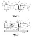
- FIG. 3illustrates a side, elevation view of one tubular connection member connector body in accordance with embodiments of the invention.
- FIG. 4illustrates a top, plan view of one tubular connection member connector body in accordance with embodiments of the invention.
- FIG. 5illustrates a perspective view of a thermoplastic elastomer in accordance with embodiments of the invention.
- FIG. 6illustrates a perspective view of a luer port cylindrical wall in accordance with embodiments of the invention.
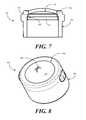
- FIG. 7illustrates a sectional view of a luer port in accordance with embodiments of the invention.
- FIG. 8illustrates a perspective view of a luer port with a slit thermoplastic elastomer in accordance with embodiments of the invention.
- FIG. 9illustrates a sectional view of a connection member having a luer port coupled thereto in accordance with embodiments of the invention.
- FIG. 10illustrates a perspective view of a connection member having a luer port coupled thereto in accordance with embodiments of the invention.
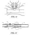
- FIG. 11illustrates a needle-less syringe with a needle hub passing through an aperture in a thermoplastic elastomer.
- FIG. 12illustrates one method for manufacturing a connector having a luer port in accordance with embodiments of the invention.
- FIG. 13illustrates one embodiment of a connector for a fluid conduit coupled to fluid conduit in accordance with one embodiment of the invention.
- Embodiments of the present inventionprovide a connector for fluid conduit, such as rubber tubing or other flexible conduit.
- the connectorincludes a luer access port, to which a luer connector of a needle-less syringe may couple.
- the needle hub of the syringecouples to the luer access port, the needle hub of the syringe is able to pass through an aperture or opening in a thermoplastic elastomer, thereby allowing one to take a fluid sample without penetrating the fluid conduit, and without the use of a hypodermic needle.
- the connectorincludes a tubular connection member having a lumen passing therethrough.
- the tubular connection memberincludes a male conduit connector and a female receiver, which can be used for coupling the connector to conduit.
- the luer access portwhich is a singular, insert-molded part in one embodiment, is disposed along a waist of the tubular connection member that is positioned between two higher side portions. To aid in user comfort, in one embodiment, the luer access port rises no higher from the waist than one of the side portions. To further aid in user comfort, in one embodiment the waist and side portions form a smooth contour without sharp edges.
- Embodiments of the present inventionfacilitate fluid flow from one conduit inserted into the female receiver and another coupled about the male conduit connector through a lumen passing along a longitudinal axis of the tubular connection member.
- the luer access portextends from the tubular connection member along a transverse axis, which may be oriented orthogonally relative to the longitudinal axis.
- the thermoplastic elastomer of the luer access portensures that fluid passes through the main lumen until either a slip luer or a lock luer is coupled to the cylindrical body of the luer access port.
- the needle hubpasses through the thermoplastic elastomer, thereby permitting fluid flow along the transverse axis into the syringe.
- fluid communication along the transverse axisstops.
- Embodiments of the present inventionoffer numerous advantages over the prior art due to manufacturability.
- prior art luer access portsare often made with many different parts
- only two partsare used, as the luer access port is formed in a single mold by way of a insert molding process.
- This manufacturing methodresults in a smaller connector having a reduced form factor, as well as a lower cost connector.
- Sizecan be important in fluid connector design as connectors in accordance with the present invention are frequently used in procedures involving catheters.
- the connectorWhen used with a catheter, the connector can be placed atop the leg of the patient. If the patient rolls over on the connector, large connectors can cause irritation.
- the smooth contours of various embodiments of the inventioninclude no sharp edges, thereby also increasing patient comfort.
- embodiments of the present inventionprovide an access port with higher reliability when compared to prior art, multi-piece designs.
- Higher reliabilityis due at least in part to the thermoplastic elastomer being “molded into” the cylindrical wall. The insert molding process thereby reduces the opportunities for elastomer failure or the opportunities for fluid to bypass about a perimeter of the elastomer member, which results in leakage.
- thermoplastic elastomeris insert molded into the cylindrical housing of the luer access port in one embodiment, the need for tediously assembling these small parts together is obviated. This results in faster manufacturing times and reduced manufacturing cost.
- thermoplastic elastomeris permanently bonded into its cylindrical housing, thereby obviating the need for adhesives or solvents to contact the thermoplastic elastomer. Additionally, since the materials are bonded together, there is no need to provide large amounts of space within the luer access port for mechanical activation of the syringe valve. This results in a luer access port having a smaller overall form factor.
- FIGS. 1-4illustrated therein is one embodiment of a connector for a fluid conduit in accordance with embodiments of the invention.
- FIG. 1illustrates a perspective view
- FIG. 2illustrates a side, sectional view
- FIG. 3illustrates a side, elevation view
- FIG. 4illustrates a top plan view.
- the figureswill be referred to collectively, with like reference numerals referring to identical or functionally similar elements throughout the separate views.
- a tubular connection member 101has a lumen 200 passing therethrough.
- the term “tubular”refers to the fact that a lumen passes through the connection member along a longitudinal axis. Note that the term “tubular” does not mean that the tubular connection member 101 must be cylindrical, although it can be.
- various contourspass long the tubular connection member 101 , and result in ramps, steps, and smooth contours.
- the tubular connection member 101is a connector body that may take any of a variety of shapes. In one illustrative embodiment, the tubular connection member 101 has a length 401 of about 3 inches, such as 2.980 inches.
- the lumen 200which passes along a longitudinal axis of the tubular connection member 100 facilitates fluid communication between a male conduit connector 102 and a female conduit receiver 202 .
- the female conduit receiver 202can be disposed beneath a side portion 109 of the port supporting region 107 .
- the male conduit connector 102can be inserted inside a first conduit 1301 , which may be rubber or plastic tubing or other suitable conduit.
- a second conduit 1302then couples within the female conduit receiver 202 , thereby facilitating fluid communication between the first conduit 1301 and the second conduit 1302 through the lumen 200 .
- the male conduit connector 102is configured as a ramp 103 extending from a steeper insertion ramp 104 disposed at a first end 105 of the tubular connection member 101 , distally along the tubular connection member, to a termination ramp 203 .
- An optional sleeve 106is disposed behind the termination ramp 203 , which extends from the termination ramp 203 to a walled stop 204 .
- the length 402 of the combined insertion ramp 104 , ramp 103 , termination ramp 203 , and sleeve 106in one embodiment, is about 1.180 inches.
- the termination ramp 203serves as a stop to retain the first conduit on the male conduit connector 102 .
- the walled stop 204helps to prevent the first conduit 1301 from sliding too far along the tubular connection member 101 .
- each of the two side portions 109 , 110is has a height 301 , 302 that is greater then a waist height 205 .
- a first side portion height 301may be 0.664 inches
- a second side portion height 302is 0.692 inches.
- the waist height 205may only be 0.400 inches.
- the length 403 of the port support region 107in one embodiment, is about 1.800 inches.
- the port support region 107has a cross sectional shape that is non-cylindrical.
- the port support region 107has an hourglass or “pinched cigarette butt” appearance as the port support region 107 tapers from a first side portion 109 to the waist 108 to the second side portion 110 .
- the waist 108 , first side portion 109 , and second side portion 110have widths 404 , 405 , 406 that are different from their respective heights 301 , 302 , 205 .
- the waist 108may have a waist height 205 of 0.400 inches
- its width 404may be 0.498 inches
- its width 405may be only 0.581 inches
- the second side portion 110may have a height of 0.692 inches
- its width 406may only be 0.638 inches.
- the widths and heights of the port support region 107could be the same as well.
- the connector 100will be used in a catheter process in which the connector 100 is placed along, or very near to, a person's leg or arm. As such, a person can roll onto the connector 100 at times.
- the surface area 112 defining the contours flowing along the port support region 107are smooth and are devoid of corners or sharp edges.
- the port receiving aperture 111includes its own lumen 206 that is disposed about a transverse axis 207 .
- the transverse axis 207is orthogonal with the longitudinal axis 201 , although other angles can be used as well.
- the port receiving aperture 111is configured to couple to the access port that will be described with respect to the figures below.
- thermoplastic elastomer 500suitable for use with embodiments of the invention. While the thermoplastic elastomer 500 is shown as an independent element in FIG. 5 , as will be described below it can be integrated into a cylindrical wall in an insert molding process. Where this is the case, the cylindrical wall and thermoplastic elastomer 500 will be removed from the mold in a single piece.
- the illustration of the thermoplastic elastomer 500 shown in FIG. 5is used to show some features and characteristics of one exemplary embodiment.
- the thermoplastic elastomer 500includes a domed interior portion 501 surrounded by a stair-stepped perimeter portion 502 .
- the stair-stepped perimeter portion 502includes two steps, although those of ordinary skill in the art having the benefit of this disclosure will understand that other numbers of steps can be used. The steps serve to provide additional surface area to which the cylindrical sidewall can adhere. Further the lower step 503 of the thermoplastic elastomer 500 may be integrated into the cylindrical sidewall, thereby leaving the domed interior portion 501 free to move.
- the thermoplastic elastomer 500is manufactured from a flexible, resilient material having both thermoplastic and elastomeric properties.
- One suitable material shown to work well in practiceis Versaflex® OM 9-802CL offered by GLS Corporation. This material is clear and readily combines with polycarbonate resins in insert molding processes.
- FIG. 6illustrated therein is one embodiment of a cylindrical wall 600 that is formed about the thermoplastic elastomer ( 500 ) of FIG. 5 .
- the cylindrical wallis shown as an independent element in FIG. 6 . However, as will be described below, it can be integrated about the thermoplastic elastomer ( 500 ) in an insert molding process. Where this is the case, the cylindrical wall 600 and thermoplastic elastomer ( 500 ) will be removed from the mold in a single piece.
- the illustration of the cylindrical wall shown in FIG. 6is used to show some features and characteristics of one exemplary embodiment.
- the cylindrical wall 600is configured as a cylinder such that it will easily slip between a luer connector and needle hub of a syringe.
- the cylindrical wall 600can be manufactured from a rigid thermoplastic, such as ABS, polycarbonate, polycarbonate-ABS, and so forth.
- polycarbonateis used for the cylindrical wall 600 due to the fact that it easily bonds with polyvinyl chloride materials with commonly available solvents such as cyclohexanone or methylene chloride.
- the cylindrical wall 600can be configured to couple with slip luer connections or locking luer connections. Where the cylindrical wall 600 is configured to couple to a locking luer connection, in one embodiment, the cylindrical wall 600 includes one or more male engagement members 601 , 602 extending therefrom. These male engagement members 601 , 602 are configured to engage the locking mechanism of a locking luer connector, which may be in the form of threads, twist snaps, or other mechanical configurations. Where the cylindrical wall 600 is configured to couple to slip luer connectors, the male engagement member 601 , 602 may be omitted. However, a cylindrical wall 600 having male engagement member 601 , 602 that only slightly protrude from the perimeter wall 603 so as to either engage the locking mechanism of a locking luer connector, or to slide within a slip luer connector.
- the cylindrical wall 600includes a terminating ledge 604 that is complementary in shape to the stair-stepped perimeter ( 502 ) of the thermoplastic elastomer ( 500 ). During the insert molding process, the terminating ledge 604 fuses with the stair-stepped perimeter ( 502 ), thereby forming a unitary luer access port.
- FIG. 7illustrated therein is one embodiment of a unitary luer access port 700 , shown in a sectional view, comprising a thermoplastic elastomer 500 and a cylindrical wall 600 .
- the unitary luer access port 700 of FIG. 7has been formed with an insert molding process, where the stair-stepped perimeter 502 mates with a complementary stair-stepped feature 701 inside the terminating ledge 604 .
- the port height 702is less than 0.200 inches.
- FIG. 8illustrated therein is another embodiment of a luer access port 800 in accordance with embodiments of the invention.
- the domed interior portion 501 of the thermoplastic elastomer 500has been cut so as to reveal an incision 802 spanning a length of the domed interior portion 501 .
- the incision 802defines an aperture that is configured such that a needle hub of a needle-less syringe may pass through the aperture so as to draw fluid samples through the luer access port 800 .
- thermoplastic elastomer 500has elastomeric properties, when the needle hub is withdrawn, the incision 802 closes, thereby stopping fluid communication through the luer access port 800 .
- the incision 802is large enough for the needle hub to fully pass therethrough. However, in one embodiment the incision 802 is not large enough to extend across the entire width of the domed interior portion 501 , as this can compromise reliability of the bond between the thermoplastic elastomer 500 with the cylindrical wall 600 .
- the function of the luer access port 800is to establish fluid communication from a syringe to the lumen of a flow channel in a connector body or tubular connection member.
- a needle hubWhen there is not a needle hub inserted into the luer access port 800 , no fluid is allowed through the thermoplastic elastomer 500 .
- the thermoplastic elastomer 500stretches and displaces, thereby allowing the needle hub to pass through the incision 802 and establish fluid communication with internal lumen of the connector body or tubular connection member.
- the healthcare providerneed only insert the needle hub through the incision 802 , thereby causing the luer connector to pass about the cylindrical wall 600 .
- the healthcare providercan then aspirate the syringe and draw a sample of fluid.
- the thermoplastic elastomer 500 materialis chosen so that it is soft enough to allow the needle hub to pass though without resistance.
- the thermoplastic elastomer 500 materialis also chosen so that it is resilient and can close quickly upon removal of the needle hub to ensure the prevention of leaks.
- FIGS. 9 and 10illustrated therein is one embodiment of a connector 900 for a fluid conduit in accordance with embodiments of the invention.
- the fluid connector 900 of FIGS. 9 and 10includes a connector body 901 having a main lumen 902 passing therethrough along a longitudinal axis 903 .
- the connector body 901in this illustrative embodiment, is configured just as was the tubular connection member ( 101 ) of FIGS. 1-4 , with a port receiving aperture 904 to which a luer access port 800 is coupled.
- the luer access port 800is coupled to the port receiving aperture 904 at the waist 905 of the connector body 901 , which is disposed between two side sections 907 , 908 .
- the luer access port 800is coupled to the port receiving aperture 904 of the connector body 901 with adhesives. In another embodiment, the luer access port 800 can be threaded into the port receiving aperture 904 . In another embodiment, the luer access port 800 can be sonically or thermally welded into the port receiving aperture 904 .
- the luer access port 800extends distally along a transverse axis 905 from a waist 906 of the connector body 901 that is disposed between two side sections 907 , 908 .
- the luer access port 800has a height 909 that is configured such that the luer access port 800 extends from the connector body 901 to a height that is less than a side section height 910 of the highest of the two side sections 907 , 908 .
- the configuration of the connector 900aids in user comfort in that the luer access port 800 is not the highest feature.
- the combination of both side sections 907 , 908 and the luer access port 800form a three-element surface that will not substantially irritate a user if the user rolls over the connector 900 .
- the height 910 of the highest of the two side portions 907 , 908is greater than or equal to a waist height 911 of the waist 906 plus the port height 909 .
- a height 910 of the higher side portion 908is 0.400 inches
- the waist height 911can be less than 0.200 inches
- the port height 909can be less than 0.200 inches.
- the heightmay be 0.346 inches, while the waist height 911 is 0.200 inches. In this configuration, the port height 909 will be less than or equal to 0.146 inches.
- FIG. 11illustrated therein is a needle hub 1100 of a needle-less syringe being inserted into one embodiment of a luer access port 800 coupled to a tubular connection member 101 in accordance with embodiments of the invention.
- the syringe of FIG. 11is a slip luer syringe, as the luer connector 1102 does not include any luer locking members. Note that even though the syringe is a slip luer syringe, the cylindrical wall 600 still includes male engagement members 601 , 602 . However, each male engagement member 601 , 602 extends from the cylindrical wall 600 sufficiently little as to fit within the luer connector 1102 .
- the needle hub 1100passes through the incision ( 802 ) of the thermoplastic elastomer 500 .
- the needle hub 1100thus enters the lumen 1103 of the luer access port 800 , thereby facilitating withdrawal of fluids from the main lumen 1104 passing through the tubular connecting member 101 .
- FIG. 12illustrated therein are exemplary methods 1200 for manufacturing a luer access port and a corresponding connector for fluid conduit with an insert molding process in accordance with embodiments of the invention.
- flow 1201is one exemplary method of forming a luer access port
- flow 1202is another. It will be obvious to those of ordinary skill in the art having the benefit of this disclosure that other insert molding process flows for creating a luer access port can be used.
- the methodincludes the following steps: forming a first portion of the luer access port in a mold by injecting a first material into a cavity of the mold as shown by steps 1203 and 1206 ; removing at least one tooling component from the cavity, thereby creating additional cavity space as shown by steps 1204 and 10207 ; and forming a second portion of the luer access port by injecting a second material into the cavity about the stair-stepped elastomer membrane to form the luer access port as shown at steps 1205 and 1208 .
- the first material injected into the moldwill be elastomer
- the second materialwill be a thermoplastic like polycarbonate.
- the first materialwill be a thermoplastic, while the second material will be an elastomer.
- this processcan be carried out using a mold having two sets of cores and cavities, where the cores are the same, but the cavities are different from each other.
- the stair-stepped elastomer and luer access port bodycan be constructed at the same time, thereby increasing efficiency of manufacture.
- Flow 1201describes a process in which the luer access port body is formed first.
- the luer access port bodyis formed by injecting a first material, such as a thermoplastic like polycarbonate, into an injection mold cavity.
- a first materialsuch as a thermoplastic like polycarbonate
- the moldcan opened with the luer access port body still within the mold, thereby forming new cavities.
- the moldcan then rotated 180 degrees out of phase so that the injection equipment is facing the additional cavities.
- a separate injection unit of the injection equipmentcan then inject a second material, such as an elastomer, into the new cavities such that it forms with the luer access port body.
- This step 1205completes the formation of a unitary, integrated luer access port.
- a connector bodyis provided.
- the connector bodyas described with respect to the embodiments above, includes a first lumen extending along a longitudinal axis and a second lumen extending along a transverse axis and intersecting the first lumen.
- an incision or slitis formed in the stair-stepped elastomer membrane so as to facilitate passage of a needle hub therethrough.
- the unitary, integrated access portis coupled to the connector body about the transverse axis as described above. The resulting connector can then be used or shipped to healthcare providers for use.
- a stair-stepped elastomer membraneis formed in a mold by injecting elastomer material into a first cavity of the mold.
- the first cavitywhich is for the stair-stepped elastomer membrane, is blocked from a second cavity for the body cores within the mold.
- At step 1207at least one tooling component, such as a core, is removed from the mold, thereby increasing a cavity size of the mold and providing exposure of the now formed stair-stepped elastomer membrane to the second cavity for the body.
- a body of a luer access portis formed by injecting thermoplastic material into the second cavity that has been exposed about the stair-stepped elastomer membrane. This step 1208 completes the formation of a unitary, integrated luer access port. The luer access port can then be formed into a connector at steps 1209 , 1210 , and 1211 , as described above.
Landscapes
- Health & Medical Sciences (AREA)
- Heart & Thoracic Surgery (AREA)
- Engineering & Computer Science (AREA)
- Hematology (AREA)
- Anesthesiology (AREA)
- Biomedical Technology (AREA)
- Pulmonology (AREA)
- Life Sciences & Earth Sciences (AREA)
- Animal Behavior & Ethology (AREA)
- General Health & Medical Sciences (AREA)
- Public Health (AREA)
- Veterinary Medicine (AREA)
- Manufacturing & Machinery (AREA)
- Mechanical Engineering (AREA)
- Infusion, Injection, And Reservoir Apparatuses (AREA)
Abstract
Description
Claims (16)
Priority Applications (2)
| Application Number | Priority Date | Filing Date | Title |
|---|---|---|---|
| US12/572,708US8764731B2 (en) | 2009-10-02 | 2009-10-02 | Connector for fluid conduit with integrated luer access port |
| US14/283,449US20140250664A1 (en) | 2009-10-02 | 2014-05-21 | Connector for Fluid Conduit with Integrated Luer Access Port |
Applications Claiming Priority (1)
| Application Number | Priority Date | Filing Date | Title |
|---|---|---|---|
| US12/572,708US8764731B2 (en) | 2009-10-02 | 2009-10-02 | Connector for fluid conduit with integrated luer access port |
Related Child Applications (1)
| Application Number | Title | Priority Date | Filing Date |
|---|---|---|---|
| US14/283,449DivisionUS20140250664A1 (en) | 2009-10-02 | 2014-05-21 | Connector for Fluid Conduit with Integrated Luer Access Port |
Publications (2)
| Publication Number | Publication Date |
|---|---|
| US20110082431A1 US20110082431A1 (en) | 2011-04-07 |
| US8764731B2true US8764731B2 (en) | 2014-07-01 |
Family
ID=43823761
Family Applications (2)
| Application Number | Title | Priority Date | Filing Date |
|---|---|---|---|
| US12/572,708Active2030-12-26US8764731B2 (en) | 2009-10-02 | 2009-10-02 | Connector for fluid conduit with integrated luer access port |
| US14/283,449AbandonedUS20140250664A1 (en) | 2009-10-02 | 2014-05-21 | Connector for Fluid Conduit with Integrated Luer Access Port |
Family Applications After (1)
| Application Number | Title | Priority Date | Filing Date |
|---|---|---|---|
| US14/283,449AbandonedUS20140250664A1 (en) | 2009-10-02 | 2014-05-21 | Connector for Fluid Conduit with Integrated Luer Access Port |
Country Status (1)
| Country | Link |
|---|---|
| US (2) | US8764731B2 (en) |
Cited By (6)
| Publication number | Priority date | Publication date | Assignee | Title |
|---|---|---|---|---|
| USD779053S1 (en)* | 2014-05-30 | 2017-02-14 | Medline Industries, Inc. | Suction handle |
| USD780306S1 (en) | 2011-09-29 | 2017-02-28 | Medline Industries, Inc. | Suction handle |
| US9884143B2 (en) | 2014-05-30 | 2018-02-06 | Medline Industries, Inc. | Medical personal-services suction handle |
| US9933094B2 (en) | 2011-09-09 | 2018-04-03 | Icu Medical, Inc. | Medical connectors with fluid-resistant mating interfaces |
| US10046154B2 (en) | 2008-12-19 | 2018-08-14 | Icu Medical, Inc. | Medical connector with closeable luer connector |
| US10179231B2 (en) | 2012-11-12 | 2019-01-15 | Icu Medical, Inc. | Medical connector |
Families Citing this family (29)
| Publication number | Priority date | Publication date | Assignee | Title |
|---|---|---|---|---|
| US9259535B2 (en) | 2006-06-22 | 2016-02-16 | Excelsior Medical Corporation | Antiseptic cap equipped syringe |
| US11229746B2 (en) | 2006-06-22 | 2022-01-25 | Excelsior Medical Corporation | Antiseptic cap |
| US9078992B2 (en) | 2008-10-27 | 2015-07-14 | Pursuit Vascular, Inc. | Medical device for applying antimicrobial to proximal end of catheter |
| DE202008016702U1 (en)* | 2008-12-18 | 2010-06-02 | Vemag Maschinenbau Gmbh | Apparatus for filling or processing pasty masses, in particular sausage meat |
| DE202009002115U1 (en)* | 2009-02-13 | 2010-07-15 | Vemag Maschinenbau Gmbh | Mixing device for food masses such as sausage meat and filling machine |
| US8764731B2 (en) | 2009-10-02 | 2014-07-01 | Medline Industries, Inc. | Connector for fluid conduit with integrated luer access port |
| USD657056S1 (en) | 2009-10-02 | 2012-04-03 | Medline Industries, Inc. | Medical port |
| US20120078215A1 (en)* | 2010-09-28 | 2012-03-29 | Tyco Healthcare Group Lp | Two-piece vial transfer needle assembly |
| WO2012162259A2 (en) | 2011-05-20 | 2012-11-29 | Excelsior Medical Corporation | Caps for cannula access devices |
| US10166381B2 (en) | 2011-05-23 | 2019-01-01 | Excelsior Medical Corporation | Antiseptic cap |
| US20140155868A1 (en)* | 2011-07-08 | 2014-06-05 | Icu Medical, Inc. | Sheath |
| WO2013009998A2 (en) | 2011-07-12 | 2013-01-17 | Pursuit Vascular, Inc. | Device for delivery of antimicrobial agent into trans-dermal catheter |
| US9737686B2 (en)* | 2012-03-12 | 2017-08-22 | Becton, Dickinson And Company | Catheter adapter port valve |
| USD757259S1 (en)* | 2012-04-05 | 2016-05-24 | Medline Industries, Inc. | Female portion of a connector |
| US10359139B2 (en) | 2012-04-05 | 2019-07-23 | Medline Industries, Inc. | Connector |
| USD719258S1 (en)* | 2012-04-19 | 2014-12-09 | Maymom LLC | Tubing connector for breast pumps |
| USD750258S1 (en)* | 2013-09-06 | 2016-02-23 | Asalus Medical Instruments Ltd | Medical instrument |
| EP3137122B1 (en) | 2014-05-02 | 2019-09-04 | Excelsior Medical Corporation | Strip package for antiseptic cap |
| DK3294404T3 (en) | 2015-05-08 | 2025-09-08 | Icu Medical Inc | MEDICAL CONNECTORS CONFIGURED TO RECEIVE EMISSIONS OF THERAPEUTIC AGENTS |
| PT3525865T (en) | 2016-10-14 | 2022-11-17 | Icu Medical Inc | Sanitizing caps for medical connectors |
| WO2018204206A2 (en) | 2017-05-01 | 2018-11-08 | Icu Medical, Inc. | Medical fluid connectors and methods for providing additives in medical fluid lines |
| EP3806948B1 (en)* | 2018-06-12 | 2025-01-08 | CardiacAssist, Inc. | Sterile connector and cannula assembly |
| US11541221B2 (en) | 2018-11-07 | 2023-01-03 | Icu Medical, Inc. | Tubing set with antimicrobial properties |
| US11534595B2 (en) | 2018-11-07 | 2022-12-27 | Icu Medical, Inc. | Device for delivering an antimicrobial composition into an infusion device |
| US11541220B2 (en) | 2018-11-07 | 2023-01-03 | Icu Medical, Inc. | Needleless connector with antimicrobial properties |
| US11517732B2 (en) | 2018-11-07 | 2022-12-06 | Icu Medical, Inc. | Syringe with antimicrobial properties |
| US11400195B2 (en) | 2018-11-07 | 2022-08-02 | Icu Medical, Inc. | Peritoneal dialysis transfer set with antimicrobial properties |
| EP3883638A1 (en) | 2018-11-21 | 2021-09-29 | ICU Medical, Inc. | Antimicrobial device comprising a cap with ring and insert |
| CA3204371A1 (en) | 2020-12-07 | 2022-06-16 | Icu Medical, Inc. | Peritoneal dialysis caps, systems and methods |
Citations (41)
| Publication number | Priority date | Publication date | Assignee | Title |
|---|---|---|---|---|
| US2538662A (en) | 1950-01-24 | 1951-01-16 | Charles C Abbott | Expendable valve unit for surgical appliances |
| USD252470S (en) | 1977-07-22 | 1979-07-24 | Abbott Laboratories | Urinary catheter adapter having a filtered air vent, or the like |
| USD259278S (en) | 1978-09-08 | 1981-05-19 | Shiley Inc. | Tubing connector for blood and other medical applications |
| USD283725S (en) | 1983-06-10 | 1986-05-06 | Baxter Travenol Laboratories, Inc. | Housing for an in-line pressure relief valve |
| USD300361S (en) | 1986-08-04 | 1989-03-21 | Hollister Incorporated | Combined venting valve and coupling for medical drainage tubes |
| US5033476A (en)* | 1986-12-11 | 1991-07-23 | Terumo Kabushiki Kaisha | Blood collecting tube |
| US5135492A (en)* | 1989-06-26 | 1992-08-04 | University Of Florida | Arterial/venous fluid transfer system |
| USD342135S (en) | 1991-10-28 | 1993-12-07 | Critikon, Inc. | Airway adapter |
| US5356369A (en) | 1992-06-11 | 1994-10-18 | Kabushiki Kaisha Japan Health | Portable vibration finger pressure massager |
| US5360413A (en) | 1991-12-06 | 1994-11-01 | Filtertek, Inc. | Needleless access device |
| US5474544A (en) | 1994-05-25 | 1995-12-12 | Lynn; Lawrence A. | Luer-receiving medical valve |
| US5501426A (en) | 1992-06-04 | 1996-03-26 | Vernay Laboratories, Inc. | Medical coupling site valve body |
| US5509433A (en) | 1993-10-13 | 1996-04-23 | Paradis; Joseph R. | Control of fluid flow |
| US5533708A (en) | 1992-06-04 | 1996-07-09 | Vernay Laboratories, Inc. | Medical coupling site valve body |
| US5616130A (en) | 1994-06-20 | 1997-04-01 | Nima Enterprises, Inc. | Needleless injection site |
| US5632735A (en) | 1992-09-29 | 1997-05-27 | Wyatt; Philip | Infusion apparatus |
| US5641184A (en)* | 1992-07-06 | 1997-06-24 | Maersk Medical A/S | Tube, especially for medical use, method of producing said tube, and tool for use in the implementation of the method |
| US5676346A (en) | 1995-05-16 | 1997-10-14 | Ivac Holdings, Inc. | Needleless connector valve |
| US5699821A (en) | 1993-10-13 | 1997-12-23 | Paradis; Joseph R. | Control of fluid flow |
| US5730418A (en) | 1996-09-30 | 1998-03-24 | The Kipp Group | Minimum fluid displacement medical connector |
| USRE35841E (en)* | 1990-09-18 | 1998-07-07 | Medex, Inc. | Needleless connector sample site |
| US5820601A (en) | 1994-06-20 | 1998-10-13 | Critical Device Corporation | Needleless injection site |
| US6036171A (en) | 1997-09-17 | 2000-03-14 | Halkey-Roberts Corporation | Swabbable valve assembly |
| US6039302A (en) | 1996-11-18 | 2000-03-21 | Nypro Inc. | Swabbable luer-activated valve |
| US6079432A (en) | 1996-07-02 | 2000-06-27 | Paradis; Joseph R. | Control of fluid flow by oval shaped valve member containing a cam interface |
| US6171287B1 (en) | 1998-05-29 | 2001-01-09 | Lawrence A. Lynn | Luer receiver and method for fluid transfer |
| US20010054423A1 (en) | 1998-11-17 | 2001-12-27 | Gray David Scott | Medical port for an emergency safety resuscitator |
| US6371936B1 (en)* | 1999-06-23 | 2002-04-16 | Mary Annette Heidick | Cannula lock with plural access ports |
| US6379340B1 (en) | 1995-03-20 | 2002-04-30 | Medimop Medical Projects Lts. | Fluid control device |
| US6605076B1 (en)* | 1988-01-25 | 2003-08-12 | Baxter International Inc. | Pre-slit injection site and tapered cannula |
| USD478662S1 (en) | 2002-04-23 | 2003-08-19 | David E. Flinchbaugh | Urinary drainage valve with sampling port |
| USD482447S1 (en) | 2002-09-17 | 2003-11-18 | Becton Dickinson And Company | Needleless luer access port |
| US6651956B2 (en) | 2002-01-31 | 2003-11-25 | Halkey-Roberts Corporation | Slit-type swabable valve |
| US20040215158A1 (en)* | 2003-04-24 | 2004-10-28 | Medpoint Corporation | In line hose connector |
| US6991215B2 (en) | 2001-08-23 | 2006-01-31 | Occupational & Medical Innovations, Ltd. | Valve for use with a syringe and which prevents backflow |
| US20060217671A1 (en)* | 2005-03-24 | 2006-09-28 | Peppel Peter W | Needleless access port valves |
| US20060252997A1 (en) | 2005-04-22 | 2006-11-09 | Wilk Patent, Llc | Medical port device, kit and associated method |
| US7811278B2 (en) | 2007-02-11 | 2010-10-12 | Cuffco, Llc | Fluid connector |
| US20110082431A1 (en) | 2009-10-02 | 2011-04-07 | Burgess James E | Connector for Fluid Conduit with Integrated Luer Access Port |
| USD652510S1 (en) | 2011-02-11 | 2012-01-17 | Value Plastics, Inc. | Connector for fluid tubing |
| US20120041391A1 (en) | 2005-07-06 | 2012-02-16 | Icu Medical, Inc. | Medical connector |
Family Cites Families (7)
| Publication number | Priority date | Publication date | Assignee | Title |
|---|---|---|---|---|
| US4385025A (en)* | 1979-10-22 | 1983-05-24 | Barry Wright Corporation | Method of coinjection molding of thermoplastic and thermoplastic elastomer |
| US4685876A (en)* | 1986-03-24 | 1987-08-11 | Cincinnati Milacron Inc. | Toggle injection molding clamping force monitor |
| DE10063696A1 (en)* | 2000-12-20 | 2002-07-18 | Siemens Ag | Method for producing a housing of a mobile communication terminal, housing and mobile communication terminal |
| DE10329484A1 (en)* | 2003-07-01 | 2005-01-27 | Robert Bosch Gmbh | Method for producing a throttle valve unit in the two-component injection molding method |
| EP3884989B1 (en)* | 2005-04-27 | 2022-07-13 | C. R. Bard, Inc. | Vascular access port |
| JP5826815B2 (en)* | 2013-12-11 | 2015-12-02 | 日機装株式会社 | Mixed injection material |
| DE102016119711B4 (en)* | 2015-10-20 | 2023-08-31 | Panasonic Intellectual Property Management Co., Ltd. | lighting device |
- 2009
- 2009-10-02USUS12/572,708patent/US8764731B2/enactiveActive
- 2014
- 2014-05-21USUS14/283,449patent/US20140250664A1/ennot_activeAbandoned
Patent Citations (41)
| Publication number | Priority date | Publication date | Assignee | Title |
|---|---|---|---|---|
| US2538662A (en) | 1950-01-24 | 1951-01-16 | Charles C Abbott | Expendable valve unit for surgical appliances |
| USD252470S (en) | 1977-07-22 | 1979-07-24 | Abbott Laboratories | Urinary catheter adapter having a filtered air vent, or the like |
| USD259278S (en) | 1978-09-08 | 1981-05-19 | Shiley Inc. | Tubing connector for blood and other medical applications |
| USD283725S (en) | 1983-06-10 | 1986-05-06 | Baxter Travenol Laboratories, Inc. | Housing for an in-line pressure relief valve |
| USD300361S (en) | 1986-08-04 | 1989-03-21 | Hollister Incorporated | Combined venting valve and coupling for medical drainage tubes |
| US5033476A (en)* | 1986-12-11 | 1991-07-23 | Terumo Kabushiki Kaisha | Blood collecting tube |
| US6605076B1 (en)* | 1988-01-25 | 2003-08-12 | Baxter International Inc. | Pre-slit injection site and tapered cannula |
| US5135492A (en)* | 1989-06-26 | 1992-08-04 | University Of Florida | Arterial/venous fluid transfer system |
| USRE35841E (en)* | 1990-09-18 | 1998-07-07 | Medex, Inc. | Needleless connector sample site |
| USD342135S (en) | 1991-10-28 | 1993-12-07 | Critikon, Inc. | Airway adapter |
| US5360413A (en) | 1991-12-06 | 1994-11-01 | Filtertek, Inc. | Needleless access device |
| US5501426A (en) | 1992-06-04 | 1996-03-26 | Vernay Laboratories, Inc. | Medical coupling site valve body |
| US5533708A (en) | 1992-06-04 | 1996-07-09 | Vernay Laboratories, Inc. | Medical coupling site valve body |
| US5356369A (en) | 1992-06-11 | 1994-10-18 | Kabushiki Kaisha Japan Health | Portable vibration finger pressure massager |
| US5641184A (en)* | 1992-07-06 | 1997-06-24 | Maersk Medical A/S | Tube, especially for medical use, method of producing said tube, and tool for use in the implementation of the method |
| US5632735A (en) | 1992-09-29 | 1997-05-27 | Wyatt; Philip | Infusion apparatus |
| US5509433A (en) | 1993-10-13 | 1996-04-23 | Paradis; Joseph R. | Control of fluid flow |
| US5699821A (en) | 1993-10-13 | 1997-12-23 | Paradis; Joseph R. | Control of fluid flow |
| US5474544A (en) | 1994-05-25 | 1995-12-12 | Lynn; Lawrence A. | Luer-receiving medical valve |
| US5820601A (en) | 1994-06-20 | 1998-10-13 | Critical Device Corporation | Needleless injection site |
| US5616130A (en) | 1994-06-20 | 1997-04-01 | Nima Enterprises, Inc. | Needleless injection site |
| US6379340B1 (en) | 1995-03-20 | 2002-04-30 | Medimop Medical Projects Lts. | Fluid control device |
| US5676346A (en) | 1995-05-16 | 1997-10-14 | Ivac Holdings, Inc. | Needleless connector valve |
| US6079432A (en) | 1996-07-02 | 2000-06-27 | Paradis; Joseph R. | Control of fluid flow by oval shaped valve member containing a cam interface |
| US5730418A (en) | 1996-09-30 | 1998-03-24 | The Kipp Group | Minimum fluid displacement medical connector |
| US6039302A (en) | 1996-11-18 | 2000-03-21 | Nypro Inc. | Swabbable luer-activated valve |
| US6036171A (en) | 1997-09-17 | 2000-03-14 | Halkey-Roberts Corporation | Swabbable valve assembly |
| US6171287B1 (en) | 1998-05-29 | 2001-01-09 | Lawrence A. Lynn | Luer receiver and method for fluid transfer |
| US20010054423A1 (en) | 1998-11-17 | 2001-12-27 | Gray David Scott | Medical port for an emergency safety resuscitator |
| US6371936B1 (en)* | 1999-06-23 | 2002-04-16 | Mary Annette Heidick | Cannula lock with plural access ports |
| US6991215B2 (en) | 2001-08-23 | 2006-01-31 | Occupational & Medical Innovations, Ltd. | Valve for use with a syringe and which prevents backflow |
| US6651956B2 (en) | 2002-01-31 | 2003-11-25 | Halkey-Roberts Corporation | Slit-type swabable valve |
| USD478662S1 (en) | 2002-04-23 | 2003-08-19 | David E. Flinchbaugh | Urinary drainage valve with sampling port |
| USD482447S1 (en) | 2002-09-17 | 2003-11-18 | Becton Dickinson And Company | Needleless luer access port |
| US20040215158A1 (en)* | 2003-04-24 | 2004-10-28 | Medpoint Corporation | In line hose connector |
| US20060217671A1 (en)* | 2005-03-24 | 2006-09-28 | Peppel Peter W | Needleless access port valves |
| US20060252997A1 (en) | 2005-04-22 | 2006-11-09 | Wilk Patent, Llc | Medical port device, kit and associated method |
| US20120041391A1 (en) | 2005-07-06 | 2012-02-16 | Icu Medical, Inc. | Medical connector |
| US7811278B2 (en) | 2007-02-11 | 2010-10-12 | Cuffco, Llc | Fluid connector |
| US20110082431A1 (en) | 2009-10-02 | 2011-04-07 | Burgess James E | Connector for Fluid Conduit with Integrated Luer Access Port |
| USD652510S1 (en) | 2011-02-11 | 2012-01-17 | Value Plastics, Inc. | Connector for fluid tubing |
Non-Patent Citations (3)
| Title |
|---|
| Goodman, Eric L., "Notice of Allowance", U.S. Appl. No. 29/344,747, filed Oct. 2, 2009; mailed Dec. 1, 2011. |
| Goodman, Eric L., "Notice of Allowance", U.S. Appl. No. 29/407,332, filed Nov. 28, 2011; mailed Apr. 20, 2012. |
| Goodman, Eric L., "Restriction Requirement", U.S. Appl. No. 29/407,332, filed Nov. 28, 2011; mailed Mar. 2, 2012. |
Cited By (18)
| Publication number | Priority date | Publication date | Assignee | Title |
|---|---|---|---|---|
| US11478624B2 (en) | 2008-12-19 | 2022-10-25 | Icu Medical, Inc. | Medical connector with closeable luer connector |
| US10046154B2 (en) | 2008-12-19 | 2018-08-14 | Icu Medical, Inc. | Medical connector with closeable luer connector |
| US12280230B2 (en) | 2008-12-19 | 2025-04-22 | Icu Medical, Inc. | Medical connector with closeable luer connector |
| US10716928B2 (en) | 2008-12-19 | 2020-07-21 | Icu Medical, Inc. | Medical connector with closeable luer connector |
| US11168818B2 (en) | 2011-09-09 | 2021-11-09 | Icu Medical, Inc. | Axially engaging medical connector system that inhibits fluid penetration between mating surfaces |
| US12320453B2 (en) | 2011-09-09 | 2025-06-03 | Icu Medical, Inc. | Medical connector with luer-incompatible connection portion |
| US9933094B2 (en) | 2011-09-09 | 2018-04-03 | Icu Medical, Inc. | Medical connectors with fluid-resistant mating interfaces |
| US10697570B2 (en) | 2011-09-09 | 2020-06-30 | Icu Medical, Inc. | Axially engaging medical connector system with diminished fluid remnants |
| US10156306B2 (en) | 2011-09-09 | 2018-12-18 | Icu Medical, Inc. | Axially engaging medical connector system with fluid-resistant mating interfaces |
| USD1042817S1 (en) | 2011-09-09 | 2024-09-17 | Icu Medical, Inc. | Medical connector |
| US11808389B2 (en) | 2011-09-09 | 2023-11-07 | Icu Medical, Inc. | Medical connectors with luer-incompatible connection portions |
| USD828548S1 (en) | 2011-09-29 | 2018-09-11 | Medline Industries, Inc. | Suction handle |
| USD780306S1 (en) | 2011-09-29 | 2017-02-28 | Medline Industries, Inc. | Suction handle |
| US10792486B2 (en) | 2012-11-12 | 2020-10-06 | Icu Medical, Inc. | Medical connector |
| US11872365B2 (en) | 2012-11-12 | 2024-01-16 | Icu Medical, Inc. | Medical connector |
| US10179231B2 (en) | 2012-11-12 | 2019-01-15 | Icu Medical, Inc. | Medical connector |
| USD779053S1 (en)* | 2014-05-30 | 2017-02-14 | Medline Industries, Inc. | Suction handle |
| US9884143B2 (en) | 2014-05-30 | 2018-02-06 | Medline Industries, Inc. | Medical personal-services suction handle |
Also Published As
| Publication number | Publication date |
|---|---|
| US20110082431A1 (en) | 2011-04-07 |
| US20140250664A1 (en) | 2014-09-11 |
Similar Documents
| Publication | Publication Date | Title |
|---|---|---|
| US8764731B2 (en) | Connector for fluid conduit with integrated luer access port | |
| US12109388B2 (en) | Needleless access connectors and valve elements therefor | |
| AU2016201947B2 (en) | New needleless access connector and method of use | |
| AU2017306658B2 (en) | Intravenous catheter apparatus with safety function and pressure controlled valve element | |
| JP6162199B2 (en) | A set of easy-to-clean connectors for liquid circuits | |
| JP2736240B2 (en) | Adapter with valve for medical instruments | |
| CA2638744C (en) | High flow rate needleless medical connector | |
| AU2001280515A1 (en) | Medical valve with positive flow characteristics | |
| CN104254361A (en) | Catheter adapter port valve | |
| CN109745615A (en) | Catheter valve is controlled using the blood of the actuator with flexible retention arm | |
| CN215537293U (en) | Infusion Connection Lines and Infusion Sets | |
| JP4744440B2 (en) | Connector | |
| CN107847728B (en) | Medical connector with two valves | |
| AU2012227226B2 (en) | Medical connector | |
| CN108785848B (en) | Anesthesia catheter connector | |
| AU2007201859A1 (en) | Medical valve with positive flow characteristics | |
| HK1140703A (en) | Needleless medical connector | |
| HK1096321A (en) | Medical valve with positive flow characteristics |
Legal Events
| Date | Code | Title | Description |
|---|---|---|---|
| AS | Assignment | Owner name:MEDLINE INDUSTRIES, INC., ILLINOIS Free format text:ASSIGNMENT OF ASSIGNORS INTEREST;ASSIGNORS:BURGESS, JAMES E., MR.;KUTSCH, JOHN H., MR.;SIGNING DATES FROM 20090928 TO 20090929;REEL/FRAME:023321/0804 | |
| STCF | Information on status: patent grant | Free format text:PATENTED CASE | |
| MAFP | Maintenance fee payment | Free format text:PAYMENT OF MAINTENANCE FEE, 4TH YEAR, LARGE ENTITY (ORIGINAL EVENT CODE: M1551) Year of fee payment:4 | |
| AS | Assignment | Owner name:BANK OF AMERICA, N.A., TEXAS Free format text:SECURITY INTEREST;ASSIGNOR:MEDLINE INDUSTRIES, LP;REEL/FRAME:058040/0001 Effective date:20211021 Owner name:WILMINGTON TRUST, NATIONAL ASSOCIATION, MINNESOTA Free format text:SECURITY INTEREST;ASSIGNOR:MEDLINE INDUSTRIES, LP;REEL/FRAME:057927/0091 Effective date:20211021 | |
| AS | Assignment | Owner name:MEDLINE INDUSTRIES, LP, ILLINOIS Free format text:CONVERSION OF ENTITY FROM CORPORATION TO LIMITED PARTNERSHIP;ASSIGNOR:MEDLINE INDUSTRIES, INC.;REEL/FRAME:057977/0567 Effective date:20210907 | |
| MAFP | Maintenance fee payment | Free format text:PAYMENT OF MAINTENANCE FEE, 8TH YEAR, LARGE ENTITY (ORIGINAL EVENT CODE: M1552); ENTITY STATUS OF PATENT OWNER: LARGE ENTITY Year of fee payment:8 | |
| AS | Assignment | Owner name:WILMINGTON TRUST, NATIONAL ASSOCIATION, AS NOTES COLLATERAL AGENT, MINNESOTA Free format text:PATENT SECURITY AGREEMENT;ASSIGNOR:MEDLINE INDUSTRIES, LP;REEL/FRAME:071672/0100 Effective date:20240327 |