US8764025B1 - Self-locking internal adapter with free guide mechanism - Google Patents
Self-locking internal adapter with free guide mechanismDownload PDFInfo
- Publication number
- US8764025B1 US8764025B1US13/229,454US201113229454AUS8764025B1US 8764025 B1US8764025 B1US 8764025B1US 201113229454 AUS201113229454 AUS 201113229454AUS 8764025 B1US8764025 B1US 8764025B1
- Authority
- US
- United States
- Prior art keywords
- securing
- assembly
- collar
- channel
- tool
- Prior art date
- Legal status (The legal status is an assumption and is not a legal conclusion. Google has not performed a legal analysis and makes no representation as to the accuracy of the status listed.)
- Active, expires
Links
Images


Classifications
- B—PERFORMING OPERATIONS; TRANSPORTING
- B23—MACHINE TOOLS; METAL-WORKING NOT OTHERWISE PROVIDED FOR
- B23B—TURNING; BORING
- B23B31/00—Chucks; Expansion mandrels; Adaptations thereof for remote control
- B23B31/02—Chucks
- B23B31/10—Chucks characterised by the retaining or gripping devices or their immediate operating means
- B23B31/107—Retention by laterally-acting detents, e.g. pins, screws, wedges; Retention by loose elements, e.g. balls
- B23B31/1071—Retention by balls
- A—HUMAN NECESSITIES
- A61—MEDICAL OR VETERINARY SCIENCE; HYGIENE
- A61B—DIAGNOSIS; SURGERY; IDENTIFICATION
- A61B17/00—Surgical instruments, devices or methods
- A61B17/56—Surgical instruments or methods for treatment of bones or joints; Devices specially adapted therefor
- A61B17/58—Surgical instruments or methods for treatment of bones or joints; Devices specially adapted therefor for osteosynthesis, e.g. bone plates, screws or setting implements
- A61B17/88—Osteosynthesis instruments; Methods or means for implanting or extracting internal or external fixation devices
- A61B17/8875—Screwdrivers, spanners or wrenches
- B—PERFORMING OPERATIONS; TRANSPORTING
- B25—HAND TOOLS; PORTABLE POWER-DRIVEN TOOLS; MANIPULATORS
- B25B—TOOLS OR BENCH DEVICES NOT OTHERWISE PROVIDED FOR, FOR FASTENING, CONNECTING, DISENGAGING OR HOLDING
- B25B23/00—Details of, or accessories for, spanners, wrenches, screwdrivers
- B25B23/0007—Connections or joints between tool parts
- B25B23/0042—Connection means between screwdriver handle and screwdriver shaft
- A—HUMAN NECESSITIES
- A61—MEDICAL OR VETERINARY SCIENCE; HYGIENE
- A61B—DIAGNOSIS; SURGERY; IDENTIFICATION
- A61B17/00—Surgical instruments, devices or methods
- A61B2017/0046—Surgical instruments, devices or methods with a releasable handle; with handle and operating part separable
- A61B2017/00464—Surgical instruments, devices or methods with a releasable handle; with handle and operating part separable for use with different instruments
- Y—GENERAL TAGGING OF NEW TECHNOLOGICAL DEVELOPMENTS; GENERAL TAGGING OF CROSS-SECTIONAL TECHNOLOGIES SPANNING OVER SEVERAL SECTIONS OF THE IPC; TECHNICAL SUBJECTS COVERED BY FORMER USPC CROSS-REFERENCE ART COLLECTIONS [XRACs] AND DIGESTS
- Y10—TECHNICAL SUBJECTS COVERED BY FORMER USPC
- Y10T—TECHNICAL SUBJECTS COVERED BY FORMER US CLASSIFICATION
- Y10T279/00—Chucks or sockets
- Y10T279/17—Socket type
- Y10T279/17128—Self-grasping
- Y10T279/17136—Yielding grasping jaws
- Y10T279/17145—Ball or roller
- Y—GENERAL TAGGING OF NEW TECHNOLOGICAL DEVELOPMENTS; GENERAL TAGGING OF CROSS-SECTIONAL TECHNOLOGIES SPANNING OVER SEVERAL SECTIONS OF THE IPC; TECHNICAL SUBJECTS COVERED BY FORMER USPC CROSS-REFERENCE ART COLLECTIONS [XRACs] AND DIGESTS
- Y10—TECHNICAL SUBJECTS COVERED BY FORMER USPC
- Y10T—TECHNICAL SUBJECTS COVERED BY FORMER US CLASSIFICATION
- Y10T279/00—Chucks or sockets
- Y10T279/17—Socket type
- Y10T279/17128—Self-grasping
- Y10T279/17171—One-way-clutch type
- Y10T279/17188—Side detent
- Y10T279/17196—Ball or roller
Definitions
- the present inventionrelates to the field of medical devices, and more specifically to a self-locking internal adapter for securing medical tools.
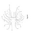
- FIG. 1is an exploded view of an exemplary embodiment of an internal adapter.
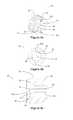
- FIGS. 2 a and 2 billustrate an exemplary embodiment of a collar assembly.
- FIG. 3is an exemplary embodiment of a house assembly.
- FIGS. 4 a , 4 b and 4 cillustrate an exemplary embodiment of a shaft driver assembly.
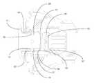
- FIG. 5is a cross-sectional view of an exemplary self-locking internal adapter with free guide mechanism.
- FIG. 6is an exemplary embodiment of the locking and securing mechanisms of a self-locking internal adapter.
- FIG. 7is an exemplary embodiment of a tool shaft for use with a self-locking internal adapter.
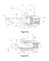
- FIGS. 8 a , 8 b and 8 cillustrate an exemplary embodiment of a self-locking internal adapter engaging an orthopedic tool.
- adapterrefers to a component of an orthopedic tool handle which engages a tool.
- chamferrefers to a beveled, angled or tapered edge which engages the edge of a second component to create a secured junction.
- flattened portionor “partially flattened portion” refer to a cylindrical surface having an area with a curvature less than that of the cylindrical curvature.
- a flattened or partially flattened portionmay contain a single area or multiple areas of lesser curvature.
- Adjustment toolsare used in orthopedic surgery to tighten and adjust mechanical components within orthopedic devices.
- screwdrivers, spreaders, pliers, hammers, cutters and other toolsmay be used to adjust screws, pins, rods and other orthopedic devices.
- the adjustment tools for adjusting these orthopedic devicesmust be highly stable to allow for precise adjustments, and many types of adjustments may be needed.
- different orthopedic toolsmay be designed to be interchangeable with a single handle.
- a typical orthopedic toolmay actually be a system of three components: a handle, an adapter and a tool.
- the handle and the adapterare structurally integrated and permanently attached to other other. Tools are adapted for insertion into the adapter.
- Adapters for securing medical tools, specifically medical tools with a square or hexagonal shaft, to handlesare known in the art. Every adapter has some sort of channel or orifice to receive the tool, and a locking mechanism to secure the tool in place. The function and simplicity of operating the locking mechanism are critical. Even incremental improvements in a locking mechanism can be critical to the outcome of a surgery.
- Toolsmust be compact to allow an orthopedic surgeon to perform adjustments to orthopedic devices and other tasks within the confined space of various body regions.
- Toolsmust also be versatile, and it is desirable to have as many tools as possible adapted for use with a single adapter and handle.
- Adapter componentsare likely to come in contact with bodily fluids and other contaminants during medical procedures. Any contours, grooves and other hard-to-reach surfaces need to be carefully cleaned and sterilized. Exposed attachment components are also more likely to be bumped or inappropriately forced in an attempt to attach a medical tool. As a result, exposed attachment components are frequently damaged.
- the present inventionis an internal adapter for use in handles for interchangeable orthopedic tools.
- a plurality of securing ball mechanismsreleasably secure an orthopedic tool in the adapter, while a configuration of chamfered surfaces centrally stabilize the tool.
- a plurality of guiding chamfers located in a shaft driver assemblyrotationally secures the orthopedic tool.
- FIG. 1is an exploded view of an exemplary embodiment of self-locking internal adapter 100 .
- Internal adapterhas collar assembly 10 , house 20 , retaining ring 30 , spring 40 , shaft driver assembly 50 , and securing balls 60 a , 60 b , 60 c , 60 d .
- collar assembly 10house 20
- retaining ring 30retains spring 40
- shaft driver assembly 50shaft driver assembly 50
- securing balls 60 a , 60 b , 60 c , 60 dWhen assembled, internal adapter 100 is configured to be secured in handle 70 .
- collar assembly 10 , house 20 , retaining ring 30 , spring 40 and shaft driver assembly 50are shown as separately manufactured components.
- two or more of collar assembly 10 , house 20 , retaining ring 30 , spring 40 and shaft driver assembly 50integrally manufactured or machined.
- one or more of collar assembly 10 , house 20 , retaining ring 30 , spring 40 and shaft driver assembly 50may be integrally manufactured with handle 70 .
- handle 70is a countered driver handle.
- internal adapter 100may be used with a torque driver, ratcheting driver, or other driver known in the art.
- retaining ring 30has gap 31 .
- retaining ring 30may be a complete ring without gaps.
- FIGS. 2 a and 2 billustrate an exemplary embodiment of collar assembly 10 .
- Collar assembly 10contains external collar base 11 and tubular sliding portion 14 , with tool receiving channel 16 extending the length of collar assembly 10 .
- tubular sliding portion 14contains securing ball apertures 15 a , 15 b 15 c , 15 d .
- Securing ball apertures 15 a , 15 b , 15 c , 15 dare equidistant and symmetrically arranged around tubular sliding portion 14 .
- tubular sliding portion 14may contain additional securing ball apertures. While equidistant and symmetrically arranged securing ball apertures provides for greater securing and stability, in further exemplary embodiments, securing ball apertures may be asymmetrically arranged and positioned at varying distances around tubular sliding portion 14 .
- Securing ball apertures 15 a , 15 b , 15 c , 15 dcontain a contoured inner surface which creates a diameter smaller than the diameter of securing balls 60 a , 60 b , 60 c , 60 d (not shown) at the innermost edge of securing ball apertures 15 a , 15 b , 15 c , 15 d .
- Securing balls 60 a , 60 b , 60 c , 60 d(not shown) are therefore freely rotatable within securing ball apertures 15 a , 15 b , 15 c , 15 d but may not pass through securing ball apertures 15 a , 15 b , 15 c , 15 d .
- securing ball apertures 15 a , 15 b , 15 c , 15 dmay contain a lip, rim, ridge or other structure which narrows the diameter of the innermost edge of securing ball apertures 15 a , 15 b , 15 c , 15 d to prevent securing balls 60 a , 60 b , 60 c , 60 d (not shown) from passing through.
- FIGS. 2 a and 2 balso show tool receiving channel 16 extending the length of collar assembly 10 .
- tool receiving channel 16is round tubular with a smooth surface and consistent internal diameter.
- tool receiving channelmay contain projections or grooves or may have an inconsistent internal diameter to accommodate a specifically manufactured tool.
- tubular sliding portion 14contains protuberance 17 and groove 18 , both of which span the external circumference of tubular sliding portion 14 .
- FIG. 3is an exemplary embodiment of house 20 .
- house 20contains external house base 21 with threaded handle-engaging stem 22 .
- Interior collar channel 23contains retaining ring securing protuberance 24 and extends the length of house 20 .
- FIGS. 4 a , 4 b and 4 cillustrate an exemplary embodiment of shaft driver assembly 50 .
- Shaft driver assembly 50has front threaded portion 51 with tapered rear portion 52 .
- Front threaded portion 51has apertures 53 a , 53 b .
- Tool guiding channel 54extends the length of shaft driver 50 .
- tool guiding channel 54is primarily round tubular with a smooth internal surface at the front of shaft driver 50 .
- the diameter of tool guiding channel 54decreases at chamfer 55 , creating interior lip 57 .
- Chamfer 55transitions tool guiding channel 54 to a narrower diameter which includes guiding chamfers 56 .
- tool guiding channel 54contains eight double square guiding chamfers 56 .
- guiding chamfersmay be hexagonal or other configuration, and tool guiding channel 54 may contain more or fewer guiding chamfers 56 to correspond to a guiding chamfer configuration.
- guiding chamfers 56do not start at the edge of chamfer 55 and have leading transition chamfer 58 .
- the proportional distance of leading transition chamfer 58 of guiding chamfers 56 from chamfer 55is a critical dimension.
- FIG. 5is a cross-sectional view of an exemplary embodiment of an assembled self-locking internal adapter 100 .
- handle 70has internal handle cavity 71 with front threaded portion 72 .
- the threads of front threaded portion 72correspond to the threads of threaded handle-engaging stem 22 and front threaded portion 51 to secure self-locking internal adapter 100 within internal handle cavity 71 .
- self-locking internal adapter 100may be configured to secure to internal handle cavity 71 through any other means known in the art, including, but not limited to, adhesives, pins, locking mechanisms, brackets, screws, contours, friction-fit components, and combination of these structures and devices.
- self-locking internal adapter 100may be an integral component of handle 70 .
- handle 70is a standard drive handle.
- handle 70may be any handle known in the art to receive orthopedic tools, including, but not limited to, torque-limiting handles and ratcheting handles.
- external house base 21 and external collar base 11are the only components of self-locking internal adapter 100 which project outside of handle 70 .
- only external collar base 11may project outside of handle 70 .
- Collar assembly 10is showed slidingly engaged with house 20 , with tubular sliding portion 14 of collar assembly 10 inside interior collar channel 23 (not shown) of house 20 .
- internal handle cavity 71also contains tapered rear portion 75 which corresponds to tapered rear portion 52 of shaft driver assembly 50 .
- tapered engagement of shaft driver assembly 50 with handle 70centers internal adapter 100 and therefore a tool.
- FIG. 6is an exemplary embodiment of the self-locking mechanism of internal adapter 100 .
- securing balls 60are contained within securing ball apertures 15 , with interior collar channel 23 of house 20 creating a cover over securing ball apertures 15 to prevent securing balls 60 from disengaging securing ball apertures 15 .
- Contoured inner surface 19 of securing ball apertures 15prevents securing balls 60 from slipping through securing ball apertures 15 and entering tool receiving channel 16 .
- the inner surface of interior collar channel 23has tapered portion 25 which corresponds to securing ball apertures 15 .
- spring 40exerts outward force on collar assembly 10
- securing balls 60 in securing ball apertures 15are forced to align with the outer-most, or narrowest, part of tapered portion 25 .
- Retaining ring 30in groove 18 , is also pushed against stop-ridge 27 of house 20 , which prevents collar assembly 10 from being forced too far outward by spring 40 .
- securing balls 60freely rotate within securing ball apertures 15 , allowing the tool shaft to proceed through tool receiving channel 16 and into tool guiding channel 54 (not shown).
- securing balls 60are forced slightly towards the inner-most, or wider, part of tapered portion 25 .
- tool receiving channel 16If the tool is pulled out from tool receiving channel 16 , securing balls 60 are forced toward the outer-most, or narrowest, part of tapered portion 25 , so that securing balls 60 are no longer able to freely rotate. The tool shaft is therefore locked within tool receiving channel 16 .
- external collar base 11is pressed inward toward handle 70 .
- Spring 40is compressed, and collar assembly 10 slides inward within interior collar channel 23 .
- Securing ball apertures 15align with the inner-most, or widest, part of tapered portion 25 , which increases the volume of securing ball apertures 15 .
- Securing balls 60are then able to freely rotated within securing ball apertures 15 , allowing the tool shaft to be pulled out of tool receiving channel 16 .
- retaining ring 30is secured in groove 18 with spring 40 positioned between and housed within house 20 and shaft driver assembly 50 .
- the front portion of spring 40rests against tubular sliding portion 14 around protuberance 17 and the rear portion of spring 40 rests against interior lip 57 of tool guiding channel 54 before transitional chamfer 55 .
- FIG. 7is an exemplary embodiment of tool shaft 82 for tool 80 which may be used with internal adapter 100 .
- tool shaft 82At one end of tool shaft 82 is handle-engaging portion 87 .
- the opposite end of tool shaft 82may contain any tool known in the art.
- groove 81transitions tool shaft 82 to handle-engaging portion 87 , which is squared with flat surfaces 85 a , 85 b ( 85 c , 85 d not shown).
- handle-engaging portionmay be hexagonal or any other configuration known in the art.
- Flat surfaces 85 a , 85 b( 85 c , 85 d not shown) each have a corresponding chamfer 83 a ( 83 b , 83 c , 83 d not shown) and are separated by rounded transitions 84 a , 84 b ( 84 c , 84 d not shown), each also have a corresponding chamfer 86 a , 86 b ( 86 c , 86 d not shown).
- the distance from the center of groove 81 and edge of chamfer 86 ais labeled as A.
- FIGS. 8 a , 8 b and 8 cillustrate an exemplary embodiment of internal adapter 100 engaging tool 80 .
- tool 80is partially inserted into internal adapter 100 .
- Chamfers 86engage securing balls 60 and force them into the larger area created by tapered portion 25 .
- Securing balls 60are able to freely rotate in securing ball apertures 15 (not shown) and tool shaft 82 is able to pass through tool receiving channel 16 .
- the distance from the center of securing balls 60 to leading transition chamfer 58 of guiding chamfers 56is labeled as B.
- distance Ais equal to distance B. It is critical that distances A and B are equal to provide quick and secure locking of tool shaft 82 in internal adapter 100 .
- tool shaft 82is further in tool receiving channel 16 , with groove 81 aligned with securing balls 60 and chamfers 86 aligned with leading transition chamfer 58 (not shown) of guiding chamfers 56 .
- flat surfaces 85must properly align with guiding chamfers 56 . Securing balls 60 do not engage tool shaft 82 in this position, allowing tool shaft 82 to freely rotate within tool receiving channel 16 and be properly oriented to engage guiding chamfers 56 .
- FIG. 8 cillustrates tool 80 secured within internal adapter 100 .
- Tool shaft 82is aligned so that handle-engaging portion 87 is aligned with guiding chamfers 56 to prevent rotational movement of tool 80 in handle 70 (not shown).
- Securing balls 60are positioned along the portion of tapered surface 25 creating a smaller volume for securing ball apertures 15 and engage tool shaft 82 and prevent movement of tool 80 out of handle 70 .
- securing balls 60are unable to rotate within securing ball apertures 15 and prevent movement of tool shaft 82 .
- collar assembly 10is pushed inward toward handle 70 to compress spring 40 .
- Securing balls 60are aligned with the portion of tapered surface 25 creating a larger volume for securing ball apertures 15 . Securing balls 60 are therefore able to freely rotate in securing ball apertures 15 , allowing tool shaft 82 to be removed from internal adapter 100 .
- chamfers 83 corresponding with flattened surfaces 85correspond to and engage leading transition chamfers 58 to stabilize tool 80 .
Landscapes
- Health & Medical Sciences (AREA)
- Engineering & Computer Science (AREA)
- Life Sciences & Earth Sciences (AREA)
- Mechanical Engineering (AREA)
- Orthopedic Medicine & Surgery (AREA)
- Surgery (AREA)
- Heart & Thoracic Surgery (AREA)
- Biomedical Technology (AREA)
- Nuclear Medicine, Radiotherapy & Molecular Imaging (AREA)
- Medical Informatics (AREA)
- Molecular Biology (AREA)
- Animal Behavior & Ethology (AREA)
- General Health & Medical Sciences (AREA)
- Public Health (AREA)
- Veterinary Medicine (AREA)
- Surgical Instruments (AREA)
Abstract
Description
The present invention relates to the field of medical devices, and more specifically to a self-locking internal adapter for securing medical tools.
As used herein, the term “adapter” refers to a component of an orthopedic tool handle which engages a tool.
As used herein, the term “chamfer” refers to a beveled, angled or tapered edge which engages the edge of a second component to create a secured junction.
As used herein, the terms “flattened portion” or “partially flattened portion” refer to a cylindrical surface having an area with a curvature less than that of the cylindrical curvature. A flattened or partially flattened portion may contain a single area or multiple areas of lesser curvature.
Adjustment tools are used in orthopedic surgery to tighten and adjust mechanical components within orthopedic devices. For example, screwdrivers, spreaders, pliers, hammers, cutters and other tools may be used to adjust screws, pins, rods and other orthopedic devices. The adjustment tools for adjusting these orthopedic devices must be highly stable to allow for precise adjustments, and many types of adjustments may be needed.
In order to save space on an operating room instrument table or in a sterilization kit, different orthopedic tools may be designed to be interchangeable with a single handle. For example, it is known in the art to fashion tools of varying lengths with shafts that may be inserted into a single tool handle.
As a result, a typical orthopedic tool may actually be a system of three components: a handle, an adapter and a tool. Generally, the handle and the adapter are structurally integrated and permanently attached to other other. Tools are adapted for insertion into the adapter.
Adapters for securing medical tools, specifically medical tools with a square or hexagonal shaft, to handles are known in the art. Every adapter has some sort of channel or orifice to receive the tool, and a locking mechanism to secure the tool in place. The function and simplicity of operating the locking mechanism are critical. Even incremental improvements in a locking mechanism can be critical to the outcome of a surgery.
Tools must be compact to allow an orthopedic surgeon to perform adjustments to orthopedic devices and other tasks within the confined space of various body regions.
Tools must also be versatile, and it is desirable to have as many tools as possible adapted for use with a single adapter and handle.
Adapter components are likely to come in contact with bodily fluids and other contaminants during medical procedures. Any contours, grooves and other hard-to-reach surfaces need to be carefully cleaned and sterilized. Exposed attachment components are also more likely to be bumped or inappropriately forced in an attempt to attach a medical tool. As a result, exposed attachment components are frequently damaged.
It is desirable to have an adapter for securing medical tools to handles which reduce the number of exposed components and surfaces.
It is desirable to have an apparatus for securing and grasping tools which is as compact as possible so that surgeons can operate within the limited spaces and contours of various regions of the body.
It is critical to have an adapter for securing medical tools in place as effectively and simply as possible.
The present invention is an internal adapter for use in handles for interchangeable orthopedic tools. A plurality of securing ball mechanisms releasably secure an orthopedic tool in the adapter, while a configuration of chamfered surfaces centrally stabilize the tool. A plurality of guiding chamfers located in a shaft driver assembly rotationally secures the orthopedic tool.
For the purpose of promoting an understanding of the present invention, references are made in the text to exemplary embodiments of an internal adapter for orthopedic tools, only some of which are described herein. It should be understood that no limitations on the scope of the invention are intended by describing these exemplary embodiments. One of ordinary skill in the art will readily appreciate that alternate but functionally equivalent structures and materials may be used. The inclusion of additional elements may be deemed readily apparent and obvious to one of ordinary skill in the art. Specific elements disclosed herein are not to be interpreted as limiting, but rather as a basis for the claims and as a representative basis for teaching one of ordinary skill in the art to employ the present invention.
It should be understood that the drawings are not necessarily to scale; instead, emphasis has been placed upon illustrating the principles of the invention. In addition, in the embodiments depicted herein, like reference numerals in the various drawings refer to identical or near identical structural elements.
As illustrated inFIG. 1 ,collar assembly 10,house 20, retainingring 30,spring 40 andshaft driver assembly 50 are shown as separately manufactured components. In further exemplary embodiments, two or more ofcollar assembly 10,house 20, retainingring 30,spring 40 andshaft driver assembly 50 integrally manufactured or machined. In still further exemplary embodiments, one or more ofcollar assembly 10,house 20, retainingring 30,spring 40 andshaft driver assembly 50 may be integrally manufactured withhandle 70.
In the exemplary embodiment shown,handle 70 is a countered driver handle. In further exemplary embodiments,internal adapter 100 may be used with a torque driver, ratcheting driver, or other driver known in the art.
As illustrated inFIG. 1 , retainingring 30 hasgap 31. In further exemplary embodiments, retainingring 30 may be a complete ring without gaps.
In further exemplary embodiments, tubular slidingportion 14 may contain additional securing ball apertures. While equidistant and symmetrically arranged securing ball apertures provides for greater securing and stability, in further exemplary embodiments, securing ball apertures may be asymmetrically arranged and positioned at varying distances aroundtubular sliding portion 14.
Securing ball apertures15a,15b,15c,15dcontain a contoured inner surface which creates a diameter smaller than the diameter of securingballs ball apertures balls ball apertures ball apertures ball apertures ball apertures balls
The rear end of tubular slidingportion 14 containsprotuberance 17 andgroove 18, both of which span the external circumference oftubular sliding portion 14.
As illustrated inFIGS. 4 a,4band4c,tool guiding channel 54 is primarily round tubular with a smooth internal surface at the front ofshaft driver 50. The diameter oftool guiding channel 54 decreases atchamfer 55, creatinginterior lip 57.Chamfer 55 transitionstool guiding channel 54 to a narrower diameter which includes guidingchamfers 56. In the exemplary embodiments shown,tool guiding channel 54 contains eight double square guiding chamfers56. In further exemplary embodiments, guiding chamfers may be hexagonal or other configuration, andtool guiding channel 54 may contain more or fewer guiding chamfers56 to correspond to a guiding chamfer configuration.
As shown inFIGS. 4 aand4c, guidingchamfers 56 do not start at the edge ofchamfer 55 and have leadingtransition chamfer 58. As will be illustrated inFIGS. 8 a,8band8c, the proportional distance of leadingtransition chamfer 58 of guidingchamfers 56 fromchamfer 55 is a critical dimension.
In the exemplary embodiment shown, handle70 is a standard drive handle. However, in further exemplary embodiments, handle70 may be any handle known in the art to receive orthopedic tools, including, but not limited to, torque-limiting handles and ratcheting handles.
As illustrated inFIG. 5 ,external house base 21 andexternal collar base 11 are the only components of self-lockinginternal adapter 100 which project outside ofhandle 70. In some exemplary embodiments, onlyexternal collar base 11 may project outside ofhandle 70.Collar assembly 10 is showed slidingly engaged withhouse 20, with tubular slidingportion 14 ofcollar assembly 10 inside interior collar channel23 (not shown) ofhouse 20.
In the exemplary embodiment shown inFIG. 5 ,internal handle cavity 71 also contains taperedrear portion 75 which corresponds to taperedrear portion 52 ofshaft driver assembly 50. The tapered engagement ofshaft driver assembly 50 withhandle 70 centersinternal adapter 100 and therefore a tool.
As shown in the exemplary embodiment illustrated inFIG. 6 , the inner surface ofinterior collar channel 23 has taperedportion 25 which corresponds to securingball apertures 15. Asspring 40 exerts outward force oncollar assembly 10, securingballs 60 in securingball apertures 15 are forced to align with the outer-most, or narrowest, part of taperedportion 25. Retainingring 30, ingroove 18, is also pushed against stop-ridge 27 ofhouse 20, which preventscollar assembly 10 from being forced too far outward byspring 40.
As a tool would be pushed intotool receiving channel 16, securingballs 60 freely rotate within securingball apertures 15, allowing the tool shaft to proceed throughtool receiving channel 16 and into tool guiding channel54 (not shown). When a tool shaft is pushed intotool receiving channel 16, securingballs 60 are forced slightly towards the inner-most, or wider, part of taperedportion 25.
If the tool is pulled out fromtool receiving channel 16, securingballs 60 are forced toward the outer-most, or narrowest, part of taperedportion 25, so that securingballs 60 are no longer able to freely rotate. The tool shaft is therefore locked withintool receiving channel 16.
To remove a tool frominternal adapter 100,external collar base 11 is pressed inward towardhandle 70.Spring 40 is compressed, andcollar assembly 10 slides inward withininterior collar channel 23. Securing ball apertures15 align with the inner-most, or widest, part of taperedportion 25, which increases the volume of securingball apertures 15. Securingballs 60 are then able to freely rotated within securingball apertures 15, allowing the tool shaft to be pulled out oftool receiving channel 16.
As illustrated inFIG. 6 , retainingring 30 is secured ingroove 18 withspring 40 positioned between and housed withinhouse 20 andshaft driver assembly 50. The front portion ofspring 40 rests against tubular slidingportion 14 aroundprotuberance 17 and the rear portion ofspring 40 rests againstinterior lip 57 oftool guiding channel 54 beforetransitional chamfer 55.
As illustrated inFIG. 7 , groove81transitions tool shaft 82 to handle-engagingportion 87, which is squared withflat surfaces
Flat surfaces85a,85b(85c,85dnot shown) each have acorresponding chamfer 83a(83b,83c,83dnot shown) and are separated byrounded transitions corresponding chamfer groove 81 and edge ofchamfer 86ais labeled as A.
As illustrated inFIG. 8 a,tool 80 is partially inserted intointernal adapter 100.Chamfers 86 engage securingballs 60 and force them into the larger area created by taperedportion 25. Securingballs 60 are able to freely rotate in securing ball apertures15 (not shown) andtool shaft 82 is able to pass throughtool receiving channel 16. The distance from the center of securingballs 60 to leadingtransition chamfer 58 of guidingchamfers 56 is labeled as B.
In the exemplary embodiment shown, distance A is equal to distance B. It is critical that distances A and B are equal to provide quick and secure locking oftool shaft 82 ininternal adapter 100.
InFIG. 8 b,tool shaft 82 is further intool receiving channel 16, withgroove 81 aligned with securingballs 60 andchamfers 86 aligned with leading transition chamfer58 (not shown) of guidingchamfers 56. In order to fullysecure tool shaft 82 ininternal adapter 100,flat surfaces 85 must properly align with guidingchamfers 56. Securingballs 60 do not engagetool shaft 82 in this position, allowingtool shaft 82 to freely rotate withintool receiving channel 16 and be properly oriented to engage guidingchamfers 56.
Iftool 80 is pulled outward fromhandle 70, securingballs 60 are unable to rotate within securingball apertures 15 and prevent movement oftool shaft 82. To releasetool 80,collar assembly 10 is pushed inward towardhandle 70 to compressspring 40. Securingballs 60 are aligned with the portion of taperedsurface 25 creating a larger volume for securingball apertures 15. Securingballs 60 are therefore able to freely rotate in securingball apertures 15, allowingtool shaft 82 to be removed frominternal adapter 100.
In the exemplary embodiment shown inFIG. 8 c, chamfers83 corresponding with flattenedsurfaces 85 correspond to and engage leadingtransition chamfers 58 to stabilizetool 80.
Claims (20)
1. An orthopedic tool apparatus comprised of:
at least one housing forming a handle and having an internal cavity; and
at least one internal adapter comprised of
a slidable collar assembly with an internal tool receiving channel, said collar assembly having a plurality of equidistant securing ball apertures and a retaining ring groove,
a house assembly with an interior collar channel having a tapered surface creating a smaller interior collar channel diameter at the front of said interior collar channel and a larger interior collar channel diameter at the rear end of said interior collar channel and a stop-ridge, wherein said slidable collar assembly is slidable within said interior collar channel and said plurality of securing ball apertures are aligned with said tapered surface,
a plurality of securing balls wherein each one of said plurality of securing balls engages one of said plurality of securing ball apertures to decrease the diameter of said internal tool receiving channel,
a retaining ring contained in said retaining ring groove,
a spring adapted to provide outward force on said slidable collar assembly so that said plurality of securing balls are aligned with said smaller interior collar channel diameter and said retaining ring engages stop-ridge to prevent outward movement of said slidable collar assembly,
a shaft driver assembly having a plurality of guiding chamfers,
wherein inward force applied to said slidable collar assembly aligns said plurality of securing balls with said larger interior collar channel diameter to increase the diameter of said tool receiving channel.
2. The apparatus ofclaim 1 wherein said internal handle cavity and said house assembly and said shaft driver assembly have corresponding threads.
3. The apparatus ofclaim 1 which has four securing balls and securing ball apertures.
4. The apparatus ofclaim 1 wherein said plurality of securing balls are freely rotatable in said securing ball apertures.
5. The apparatus ofclaim 1 wherein said guiding chamfers are double square.
6. The apparatus ofclaim 1 wherein said collar assembly includes an external collar base.
7. The apparatus ofclaim 1 wherein said shaft driver assembly and said internal cavity have corresponding tapered centralizing portions.
8. A handle for a medical shaft comprised of:
an integrally machined collar assembly having a collar base portion, an internal tool receiving channel and an internal tubular sliding portion with a groove and protuberance, wherein said internal tubular sliding portion contains four securing ball apertures symmetrically arranged around said tubular sliding portion;
an integrally machined house assembly comprised of an external house base and an interior collar channel with a stop-ridge, wherein said interior collar channel has a tapered portion of interior surface near the front of said interior collar channel;
wherein said internal tubular sliding portion of said collar assembly is slidingly engaged with said interior collar channel of said house assembly such that said four securing ball apertures are aligned with said tapered portion of said interior collar channel;
four securing balls, each engaged with and freely rotatable in one of said securing ball apertures, wherein said tapered portion of said interior collar channel secures said securing balls in said securing ball apertures;
a retaining ring contained in said groove,
a spring having an inner diameter larger than the diameter of said protuberance on said internal tubular sliding portion allowing said spring to provide an outward force on said collar assembly, wherein outward movement of said collar assembly is prevented by said securing ring engaging said stop-ridge; and
a shaft driver assembly securing said spring against said collar assembly, wherein said shaft driver assembly has a plurality of guiding chamfers corresponding to the flattened portions of an orthopedic tool;
wherein said collar assembly, said house assembly, said securing balls, said retaining ring, said spring and said shaft driver assembly are housed within a medical tool handle.
9. The apparatus ofclaim 8 wherein said medical tool handle and said shaft driver assembly contain corresponding tapered centralizing portions.
10. The apparatus ofclaim 8 wherein said house assembly and said shaft driver assembly contain outer threaded portions to engage said medical tool handle.
11. The apparatus ofclaim 8 wherein said securing ball apertures are contoured on their inward facing edge to have a diameter small than the diameter of said securing balls.
12. The apparatus ofclaim 8 wherein said collar base portion and said house base portion are external to said handle.
13. The apparatus ofclaim 8 wherein said shaft driver assembly has eight double-square guiding chamfers.
14. The apparatus ofclaim 8 wherein each of said guiding chamfers contains a stabilizing leading transition chamfer.
15. The apparatus ofclaim 8 wherein said medical handle is configured for use with a medical tool having a handle-engaging portion with a groove and a plurality of flattened surfaces separated by rounded transitions having corresponding chamfers, wherein the distance from the center of said groove to the leading edge of said corresponding chamfers is equal to the distance from the center of one of said securing balls to the leading edge of one of said guiding chamfers.
16. An orthopedic tool system comprised of:
an orthopedic tool handle having an inner handle cavity with a tapered rear portion;
an orthopedic tool having a shaft with a groove and a plurality of flattened surfaces having corresponding chamfers and separated by rounded transitions have corresponding chamfers; and
an internal orthopedic tool adapter comprising
an integrally machined collar assembly having a collar base portion, an internal tool receiving channel and an internal tubular sliding portion with a groove and a protuberance, wherein said internal tubular sliding portion contains four securing ball apertures contoured on their inward facing edge to have a smaller first diameter and symmetrically arranged around said tubular sliding portion;
an integrally machined house assembly comprised of an external house base and an interior collar channel with a stop-ridge, wherein said interior collar channel has a tapered portion of interior surface near the front of said interior collar channel creating a narrower diameter near said front of said interior collar channel and a larger diameter near the rear of said interior collar channel;
wherein said internal tubular sliding portion of said collar assembly is slidingly engaged with said interior collar channel of said house assembly such that said four securing ball apertures are aligned with said tapered portion of said interior collar channel;
four securing balls, each engaged with and freely rotatable in one of said securing ball apertures, wherein said tapered portion of said interior collar engaging channel secures said securing balls in said securing ball apertures and wherein said first smaller diameter is less than the diameter of said securing balls;
a retaining ring contained in said groove;
a spring having an inner diameter larger than the diameter of said protuberance on said internal tubular sliding portion allowing said spring to provide an outward force on said collar assembly, wherein outward movement of said collar assembly is prevented by said securing ring engaging said stop-ridge; and
a shaft driver assembly securing said spring against said collar assembly, wherein said shaft driver assembly has a plurality of guiding chamfers corresponding to said flattened surfaces of said orthopedic tool and a tapered rear portion, wherein said guiding chamfers have leading transitional chamfers,
wherein the distance from the center of said groove to the leading edge of said chamfers corresponding to said rounded transitions of said tool shaft is equal to the distance from the center of one of said securing balls to the leading edge of one of said leading transitional chamfers of said shaft driver assembly,
wherein said internal orthopedic tool adapter is secured in said inner handle cavity and centralized by said tapered rear portion of said shaft driver assembly engaging said tapered rear portion of said internal handle cavity, and
wherein said orthopedic tool is removable within said internal tool receiving channel, slidingly and rotationally secured by said securing balls engaging said shaft and centrally secured by said chamfers on said shaft which correspond to said rounded transitions engaging said leading transition chamfers of said shaft driver.
17. The system ofclaim 16 wherein said inner handle cavity is threaded and said house assembly and said shaft driver assembly have a corresponding threaded exterior surface.
18. The system ofclaim 16 wherein the distance from the center of said groove on said orthopedic tool to leading edge of said chamfers corresponding to said rounded transitions is equal to the distance from the center of one of said securing balls to the leading edge of one of said guiding chamfers.
19. The system ofclaim 16 wherein inward force applied to said slidable collar assembly aligns said securing balls with said larger interior collar channel diameter to increase the diameter of said receiving channel.
20. The system ofclaim 16 wherein said securing balls are freely rotatable and disengaged from said tool shaft at said groove.
Priority Applications (1)
| Application Number | Priority Date | Filing Date | Title |
|---|---|---|---|
| US13/229,454US8764025B1 (en) | 2011-09-09 | 2011-09-09 | Self-locking internal adapter with free guide mechanism |
Applications Claiming Priority (1)
| Application Number | Priority Date | Filing Date | Title |
|---|---|---|---|
| US13/229,454US8764025B1 (en) | 2011-09-09 | 2011-09-09 | Self-locking internal adapter with free guide mechanism |
Publications (1)
| Publication Number | Publication Date |
|---|---|
| US8764025B1true US8764025B1 (en) | 2014-07-01 |
Family
ID=50981963
Family Applications (1)
| Application Number | Title | Priority Date | Filing Date |
|---|---|---|---|
| US13/229,454Active2033-01-17US8764025B1 (en) | 2011-09-09 | 2011-09-09 | Self-locking internal adapter with free guide mechanism |
Country Status (1)
| Country | Link |
|---|---|
| US (1) | US8764025B1 (en) |
Cited By (18)
| Publication number | Priority date | Publication date | Assignee | Title |
|---|---|---|---|---|
| US20120103144A1 (en)* | 2010-10-29 | 2012-05-03 | Gauthier Michael T | Shaft Securing Mechanism for a Tool |
| US8919230B1 (en)* | 2012-01-16 | 2014-12-30 | Hua Gao | Torque-limiting driver with a self-locking adapter |
| US20150102567A1 (en)* | 2013-10-16 | 2015-04-16 | Fu-Yi Chan | Tool joint |
| JP2016036646A (en)* | 2014-08-11 | 2016-03-22 | 京セラメディカル株式会社 | Grip for artificial joint surgical instrument and shell positioner |
| US20170298728A1 (en)* | 2016-04-18 | 2017-10-19 | Jian-Shiou Liaw | Chisel Holder |
| US20180344304A1 (en)* | 2017-05-31 | 2018-12-06 | Medos International Sarl | Instrument couplings and related methods |
| US10722223B2 (en) | 2017-05-31 | 2020-07-28 | Medos International Sarl | Coupling devices for surgical instruments and related methods |
| US20220071712A1 (en)* | 2020-09-09 | 2022-03-10 | Augmedics Ltd. | Universal tool adapter |
| US20220184789A1 (en)* | 2020-12-10 | 2022-06-16 | Chun Po Huang | Removal Apparatus of Threaded Post |
| US11389942B1 (en) | 2019-01-08 | 2022-07-19 | Seaspine Orthopedics Corporation | Securing mechanism for a shaft |
| US12178666B2 (en) | 2019-07-29 | 2024-12-31 | Augmedics Ltd. | Fiducial marker |
| US12186028B2 (en) | 2020-06-15 | 2025-01-07 | Augmedics Ltd. | Rotating marker for image guided surgery |
| US12201384B2 (en) | 2018-11-26 | 2025-01-21 | Augmedics Ltd. | Tracking systems and methods for image-guided surgery |
| US12206837B2 (en) | 2015-03-24 | 2025-01-21 | Augmedics Ltd. | Combining video-based and optic-based augmented reality in a near eye display |
| US12290416B2 (en) | 2018-05-02 | 2025-05-06 | Augmedics Ltd. | Registration of a fiducial marker for an augmented reality system |
| US12354227B2 (en) | 2022-04-21 | 2025-07-08 | Augmedics Ltd. | Systems for medical image visualization |
| US12383369B2 (en) | 2019-12-22 | 2025-08-12 | Augmedics Ltd. | Mirroring in image guided surgery |
| US12417595B2 (en) | 2021-08-18 | 2025-09-16 | Augmedics Ltd. | Augmented-reality surgical system using depth sensing |
Citations (18)
| Publication number | Priority date | Publication date | Assignee | Title |
|---|---|---|---|---|
| US1307937A (en) | 1919-06-24 | Interchangeable-tool holder | ||
| US2289583A (en) | 1941-01-09 | 1942-07-14 | Frank J Malone | Tool holder |
| US2838266A (en)* | 1954-11-01 | 1958-06-10 | Cameron W Sparks | Adjustable strut |
| US3039781A (en)* | 1960-10-18 | 1962-06-19 | Bilz Otto | Tool chuck |
| US3398965A (en)* | 1966-05-26 | 1968-08-27 | Balas Collet Company | Quick change tool holder |
| US3521895A (en)* | 1968-07-24 | 1970-07-28 | Theodore M Smith | Tool holder |
| US4412764A (en)* | 1980-11-10 | 1983-11-01 | Wawrzyniak Walter W | Double ended tap |
| DE4105515A1 (en)* | 1991-02-22 | 1992-08-27 | Karl Pflumm Gmbh | Quick change chuck for rotational tools - has centralising balls caged in chuck sleeve and clamping between tool and tapered grooves in spindle bore |
| US5464229A (en)* | 1994-05-26 | 1995-11-07 | Power Tool Holders, Inc. | Quick release chuck device |
| US5741263A (en) | 1997-04-18 | 1998-04-21 | Midas Rex Pneumatic Tools, Inc. | Mutiple flat quick release coupling |
| US5928241A (en) | 1995-06-14 | 1999-07-27 | Sodem Diffusion S.A. | Quick connection method and device, and surgical instrument for driving interchangeable rotary tools |
| US6059296A (en)* | 1998-05-13 | 2000-05-09 | Otto Bilz, Werkzeugfabrik Gmbh & Co. | Chuck for rotatable tools, in particular drills, screw taps, etc. |
| US6179302B1 (en) | 1999-11-02 | 2001-01-30 | Beere Precision Medical Instruments, Inc. | Adapter for a driver of a rotary tool and method |
| US6901826B2 (en)* | 2003-09-30 | 2005-06-07 | Chin-Tan Huang | Screwdriver |
| US7086313B2 (en) | 2003-12-11 | 2006-08-08 | Jore Corporation | Screwdriver connector |
| US7325811B2 (en)* | 2004-07-23 | 2008-02-05 | Hilti Aktiengesellschaft | Chuck |
| US7500811B2 (en)* | 2005-02-18 | 2009-03-10 | Zettl Gmbh | Thread cutting tap retainer |
| US7810817B1 (en) | 2006-11-20 | 2010-10-12 | Bradshaw Medical, Inc. | Holder for replaceable tools |
- 2011
- 2011-09-09USUS13/229,454patent/US8764025B1/enactiveActive
Patent Citations (18)
| Publication number | Priority date | Publication date | Assignee | Title |
|---|---|---|---|---|
| US1307937A (en) | 1919-06-24 | Interchangeable-tool holder | ||
| US2289583A (en) | 1941-01-09 | 1942-07-14 | Frank J Malone | Tool holder |
| US2838266A (en)* | 1954-11-01 | 1958-06-10 | Cameron W Sparks | Adjustable strut |
| US3039781A (en)* | 1960-10-18 | 1962-06-19 | Bilz Otto | Tool chuck |
| US3398965A (en)* | 1966-05-26 | 1968-08-27 | Balas Collet Company | Quick change tool holder |
| US3521895A (en)* | 1968-07-24 | 1970-07-28 | Theodore M Smith | Tool holder |
| US4412764A (en)* | 1980-11-10 | 1983-11-01 | Wawrzyniak Walter W | Double ended tap |
| DE4105515A1 (en)* | 1991-02-22 | 1992-08-27 | Karl Pflumm Gmbh | Quick change chuck for rotational tools - has centralising balls caged in chuck sleeve and clamping between tool and tapered grooves in spindle bore |
| US5464229A (en)* | 1994-05-26 | 1995-11-07 | Power Tool Holders, Inc. | Quick release chuck device |
| US5928241A (en) | 1995-06-14 | 1999-07-27 | Sodem Diffusion S.A. | Quick connection method and device, and surgical instrument for driving interchangeable rotary tools |
| US5741263A (en) | 1997-04-18 | 1998-04-21 | Midas Rex Pneumatic Tools, Inc. | Mutiple flat quick release coupling |
| US6059296A (en)* | 1998-05-13 | 2000-05-09 | Otto Bilz, Werkzeugfabrik Gmbh & Co. | Chuck for rotatable tools, in particular drills, screw taps, etc. |
| US6179302B1 (en) | 1999-11-02 | 2001-01-30 | Beere Precision Medical Instruments, Inc. | Adapter for a driver of a rotary tool and method |
| US6901826B2 (en)* | 2003-09-30 | 2005-06-07 | Chin-Tan Huang | Screwdriver |
| US7086313B2 (en) | 2003-12-11 | 2006-08-08 | Jore Corporation | Screwdriver connector |
| US7325811B2 (en)* | 2004-07-23 | 2008-02-05 | Hilti Aktiengesellschaft | Chuck |
| US7500811B2 (en)* | 2005-02-18 | 2009-03-10 | Zettl Gmbh | Thread cutting tap retainer |
| US7810817B1 (en) | 2006-11-20 | 2010-10-12 | Bradshaw Medical, Inc. | Holder for replaceable tools |
Cited By (26)
| Publication number | Priority date | Publication date | Assignee | Title |
|---|---|---|---|---|
| US11794318B2 (en) | 2010-10-29 | 2023-10-24 | Gauthier Biomedical, Inc. | Shaft securing mechanism for a tool |
| US9027219B2 (en)* | 2010-10-29 | 2015-05-12 | Gauthier Biomedical, Inc. | Shaft securing mechanism for a tool |
| US20120103144A1 (en)* | 2010-10-29 | 2012-05-03 | Gauthier Michael T | Shaft Securing Mechanism for a Tool |
| US8919230B1 (en)* | 2012-01-16 | 2014-12-30 | Hua Gao | Torque-limiting driver with a self-locking adapter |
| US20150102567A1 (en)* | 2013-10-16 | 2015-04-16 | Fu-Yi Chan | Tool joint |
| JP2016036646A (en)* | 2014-08-11 | 2016-03-22 | 京セラメディカル株式会社 | Grip for artificial joint surgical instrument and shell positioner |
| US12206837B2 (en) | 2015-03-24 | 2025-01-21 | Augmedics Ltd. | Combining video-based and optic-based augmented reality in a near eye display |
| US20170298728A1 (en)* | 2016-04-18 | 2017-10-19 | Jian-Shiou Liaw | Chisel Holder |
| US20180344304A1 (en)* | 2017-05-31 | 2018-12-06 | Medos International Sarl | Instrument couplings and related methods |
| US11117197B2 (en)* | 2017-05-31 | 2021-09-14 | Medos International Sarl | Instrument couplings and related methods |
| US12226085B2 (en) | 2017-05-31 | 2025-02-18 | Medos International Sàrl | Coupling devices for surgical instruments and related methods |
| US10722223B2 (en) | 2017-05-31 | 2020-07-28 | Medos International Sarl | Coupling devices for surgical instruments and related methods |
| US11751856B2 (en) | 2017-05-31 | 2023-09-12 | Medos International Sarl | Coupling devices for surgical instruments and related methods |
| US12290416B2 (en) | 2018-05-02 | 2025-05-06 | Augmedics Ltd. | Registration of a fiducial marker for an augmented reality system |
| US12201384B2 (en) | 2018-11-26 | 2025-01-21 | Augmedics Ltd. | Tracking systems and methods for image-guided surgery |
| US11389942B1 (en) | 2019-01-08 | 2022-07-19 | Seaspine Orthopedics Corporation | Securing mechanism for a shaft |
| US12178666B2 (en) | 2019-07-29 | 2024-12-31 | Augmedics Ltd. | Fiducial marker |
| US12383369B2 (en) | 2019-12-22 | 2025-08-12 | Augmedics Ltd. | Mirroring in image guided surgery |
| US12186028B2 (en) | 2020-06-15 | 2025-01-07 | Augmedics Ltd. | Rotating marker for image guided surgery |
| US12239385B2 (en)* | 2020-09-09 | 2025-03-04 | Augmedics Ltd. | Universal tool adapter |
| US20220071712A1 (en)* | 2020-09-09 | 2022-03-10 | Augmedics Ltd. | Universal tool adapter |
| US11890735B2 (en)* | 2020-12-10 | 2024-02-06 | Taiwan Specialty Tool Company | Slide hammer having a removable actuation element |
| US20220184789A1 (en)* | 2020-12-10 | 2022-06-16 | Chun Po Huang | Removal Apparatus of Threaded Post |
| US12417595B2 (en) | 2021-08-18 | 2025-09-16 | Augmedics Ltd. | Augmented-reality surgical system using depth sensing |
| US12354227B2 (en) | 2022-04-21 | 2025-07-08 | Augmedics Ltd. | Systems for medical image visualization |
| US12412346B2 (en) | 2022-04-21 | 2025-09-09 | Augmedics Ltd. | Methods for medical image visualization |
Similar Documents
| Publication | Publication Date | Title |
|---|---|---|
| US8764025B1 (en) | Self-locking internal adapter with free guide mechanism | |
| US8985593B1 (en) | Self-locking internal adapter for D-shaped orthopedic adjustment tools | |
| US8919230B1 (en) | Torque-limiting driver with a self-locking adapter | |
| US7762164B2 (en) | Torque-limiting device | |
| US7452361B2 (en) | System with a screwdriver and a bone screw | |
| US10596687B2 (en) | Torque socket having locking and releasing function | |
| US8087329B2 (en) | Screwdriver for bone screws | |
| US9511484B2 (en) | Ratcheting screwdriver | |
| US8366120B2 (en) | Chuck for bit | |
| EP2133175B1 (en) | Chuck for a bit | |
| US8419760B2 (en) | Cutting accessory for a powered surgical handpiece, the cutting accessory including features to facilitate the alignment of the accessory with the handpiece, hold the accessory to the handpiece, facilitate the transfer of torque to the accessory and reduce the wobble of the accessory | |
| JP6953132B2 (en) | screwdriver | |
| US9447803B1 (en) | AO quick connect interface | |
| US9597135B1 (en) | Bone screw inserter | |
| US10092302B2 (en) | Coupling device for medical instrument or medical power-tool chuck | |
| ZA200608186B (en) | Extraction screwdriver | |
| US20230301664A1 (en) | Multiple Connection Drive Shaft | |
| US9458890B1 (en) | Square quick connect interface | |
| US11794318B2 (en) | Shaft securing mechanism for a tool | |
| US20080190252A1 (en) | Global nail screw retaining screwdriver | |
| US11944502B2 (en) | Torque limiting ratcheting handle for medical instrument | |
| US6543317B1 (en) | Screw holder and torquing tool | |
| US20190151001A1 (en) | Fastening device and tool for surgical holding systems | |
| US20160107296A1 (en) | Basin wrench | |
| JP2017056014A (en) | Bone anchoring device, holding sleeve, and screw |
Legal Events
| Date | Code | Title | Description |
|---|---|---|---|
| AS | Assignment | Owner name:BRADSHAW MEDICAL, INC., WISCONSIN Free format text:ASSIGNMENT OF ASSIGNORS INTEREST;ASSIGNOR:GAO, HUA;REEL/FRAME:026883/0008 Effective date:20110907 | |
| STCF | Information on status: patent grant | Free format text:PATENTED CASE | |
| MAFP | Maintenance fee payment | Free format text:PAYMENT OF MAINTENANCE FEE, 4TH YR, SMALL ENTITY (ORIGINAL EVENT CODE: M2551) Year of fee payment:4 | |
| MAFP | Maintenance fee payment | Free format text:PAYMENT OF MAINTENANCE FEE, 8TH YR, SMALL ENTITY (ORIGINAL EVENT CODE: M2552); ENTITY STATUS OF PATENT OWNER: SMALL ENTITY Year of fee payment:8 | |
| AS | Assignment | Owner name:OHA AGENCY LLC, AS COLLATERAL AGENT, NEW YORK Free format text:SECURITY INTEREST;ASSIGNORS:PIONEER SURGICAL TECHNOLOGY, INC.;TYBER MEDICAL LLC;SMADE SAS;AND OTHERS;REEL/FRAME:071575/0563 Effective date:20250612 |