US8763795B1 - Dual support flap case - Google Patents
Dual support flap caseDownload PDFInfo
- Publication number
- US8763795B1 US8763795B1US13/747,992US201313747992AUS8763795B1US 8763795 B1US8763795 B1US 8763795B1US 201313747992 AUS201313747992 AUS 201313747992AUS 8763795 B1US8763795 B1US 8763795B1
- Authority
- US
- United States
- Prior art keywords
- panel
- case
- support flap
- support
- proximate
- Prior art date
- Legal status (The legal status is an assumption and is not a legal conclusion. Google has not performed a legal analysis and makes no representation as to the accuracy of the status listed.)
- Expired - Fee Related
Links
Images


Classifications
- B—PERFORMING OPERATIONS; TRANSPORTING
- B65—CONVEYING; PACKING; STORING; HANDLING THIN OR FILAMENTARY MATERIAL
- B65D—CONTAINERS FOR STORAGE OR TRANSPORT OF ARTICLES OR MATERIALS, e.g. BAGS, BARRELS, BOTTLES, BOXES, CANS, CARTONS, CRATES, DRUMS, JARS, TANKS, HOPPERS, FORWARDING CONTAINERS; ACCESSORIES, CLOSURES, OR FITTINGS THEREFOR; PACKAGING ELEMENTS; PACKAGES
- B65D85/00—Containers, packaging elements or packages, specially adapted for particular articles or materials
- A—HUMAN NECESSITIES
- A45—HAND OR TRAVELLING ARTICLES
- A45C—PURSES; LUGGAGE; HAND CARRIED BAGS
- A45C11/00—Receptacles for purposes not provided for in groups A45C1/00-A45C9/00
- A—HUMAN NECESSITIES
- A45—HAND OR TRAVELLING ARTICLES
- A45C—PURSES; LUGGAGE; HAND CARRIED BAGS
- A45C11/00—Receptacles for purposes not provided for in groups A45C1/00-A45C9/00
- A45C11/003—Receptacles for purposes not provided for in groups A45C1/00-A45C9/00 for storing portable computing devices, e.g. laptops, tablets or calculators
- A—HUMAN NECESSITIES
- A45—HAND OR TRAVELLING ARTICLES
- A45C—PURSES; LUGGAGE; HAND CARRIED BAGS
- A45C2200/00—Details not otherwise provided for in A45C
- A45C2200/15—Articles convertible into a stand, e.g. for displaying purposes
Definitions
- the present inventionrelates, generally, to cases and accessories for portable electronic devices.
- Embodiments of the present disclosureprovide an accessory case for a portable electronic device, the case being configured to protect the portable electronic device from damage.
- the accessory casesecurely retains the portable electronic device.
- the casemay be configured in a closed position, in an open position, and in a plurality of supported (i.e., propped up) positions.
- the casecomprises two support panels or flaps configured to support the case in a first supported (i.e., elevated) position and a second supported (i.e., elevated) position.
- These support flapsallow the case to be arranged at different angles with respect to a supporting surface.
- the first and second supported positionsallow the user to choose at least two different angles at which to view a portable electronic device that has been placed inside the case.
- the usermay selectively arrange the case at a viewing angle best suited for a particular task (e.g., typing, gaming, viewing media) or for a particular surface (e.g., whether the case rests on a flat surface or an angled surface).
- the casemay be selectively arranged so that the screen of the personal electronic device is at a portrait orientation or at a landscape orientation.
- FIG. 1Adepicts one embodiment of a case arranged in a first open configuration.
- FIG. 1Bdepicts another embodiment of a case arranged in a first open configuration.
- FIG. 1Cdepicts a perspective view of one embodiment of a case arranged in a first open configuration.
- FIG. 2Adepicts one embodiment of a case arranged in a second open configuration.
- FIG. 2Bdepicts another embodiment of a case arranged in a second open configuration.
- FIG. 2Cdepicts a side view of one embodiment of a case arranged in a second open configuration.
- FIG. 3Adepicts a perspective view of one embodiment of a case arranged in a closed configuration.
- FIG. 3Bdepicts another embodiment of a case arranged in a first open configuration.
- FIG. 4Adepicts another embodiment of a case arranged in a first open configuration.
- FIG. 4Bdepicts a perspective view of another embodiment of a case arranged in a first open configuration.
- FIG. 4Cdepicts a perspective view of one embodiment of a case arranged in a second open configuration and in a first supported position.
- FIG. 4Ddepicts a side view of one embodiment of a case arranged in a second open configuration and in a first supported position.
- FIG. 5Adepicts a perspective view of another embodiment of a case arranged in a first open configuration.
- FIG. 5Bdepicts a perspective view of one embodiment of a case arranged in a second open configuration and in a second supported position.
- FIG. 5Cdepicts a side view of one embodiment of a case arranged in a second open configuration and in a second supported position.
- FIG. 6Adepicts another embodiment of a case arranged in a first open configuration.
- FIG. 6Bdepicts a perspective view of one embodiment of a case arranged in a second open configuration and in a third supported position.
- FIG. 6Cdepicts a perspective view of another embodiment of a case arranged in a second open configuration and in a third supported position.
- Portable electronic devicesprovide users with mobile computing.
- Mobile computingenhances personal activity and business productivity.
- Portable electronic devicesinclude laptop computers, notebook computers, subnotebook computers, netbook computers, ultraportable computers (e.g., ultrabooks or slimbooks), ultra-mobile PCs, smartbook computers, tablet computers, smartphones, personal digital assistants, mobile internet devices, electronic reading devices, portable media players, digital cameras, and the like.
- Portable electronic devicesare generally more at risk to damage than traditional non-portable computing devices. As portable electronic devices are carried by users, there is a risk that these devices may be dropped or may collide with other objects. There is also risk that these devices will be scratched or otherwise marred when placed in pockets, purses, book bags, drawers, or the like. Accordingly, many users seek to protect their portable devices from harm by encasing their devices in protective cases. Protective cases not only protect against scratches, dents, and the like; they also protect against environmental damage such as degradation due to exposure to sunlight, dust, or other elements.
- Embodiments of the present disclosureprovide an accessory case for a portable electronic device, the case being configured to protect the portable electronic device from damage.
- the accessory casesecurely retains the portable electronic device.
- the accessory casecomprises a bifold case that may be configured in a closed position, in an open position, and in a plurality of supported (i.e., raised) positions.
- the casecomprises two support panels or flaps configured to support the case in a first supported (i.e., elevated) position and a second supported (i.e., elevated) position.
- These support flapsallow the case to be arranged at different angles with respect to a supporting surface.
- the first and second supported or raised positionsallow the user to choose at least two different angles at which to view a portable electronic device that has been placed inside the case.
- the usermay selectively arrange the case at a viewing angle best suited for a particular task (e.g., typing, gaming, viewing media) or for a particular surface (e.g., whether the case rests on a flat surface or an angled surface).
- the casemay be selectively arranged so that the screen of the personal electronic device is at a portrait orientation or at a landscape orientation.
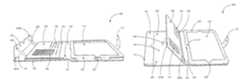
- FIGS. 1A-1Care views illustrating one embodiment of a bifold case 100 for a portable electronic device 101 .
- the bifold case 100includes a first panel 110 and a second panel 130 joined by a panel connector 160 , a device receptacle 120 mounted on the first panel 110 , a first support flap 140 mounted on the second panel 130 , and a second support flap 150 mounted on the second panel 130 .
- the bifold case 100further comprises a case closure 170 .
- FIG. 1Ais a top view of the bifold case 100 in a first opened position with first panel 110 and the second panel 130 extended to be approximately parallel.
- FIGS. 1Ais a top view of the bifold case 100 in a first opened position with first panel 110 and the second panel 130 extended to be approximately parallel.
- the bifold case 100is configured to selectively protect a portable electronic device 101 and to selectively support the portable electronic device 101 in one or more elevated positions.
- the first support flap 140is configured to selectively support the bifold case 100 and/or the portable electronic device 101 in a first elevated position while the second support flap 150 is configured to selectively support the bifold case 100 and/or the portable electronic device 101 in a second elevated position.
- a portable electronic device 101has been placed in the device receptacle 120 of the bifold case 100 of FIG. 1A .
- the portable electronic device 101may be any portable electronic device including, for example, a laptop computer, a notebook or subnotebook computer, a netbook computer, an ultraportable computer (e.g., a Intel® defined UltrabookTM), an ultra-mobile PC, a smartbook computer, a tablet computer, a smartphone, a personal digital assistant (PDA), a mobile internet device, an electronic reading device, a portable media player, a digital camera, and the like.
- a laptop computere.g., a notebook or subnotebook computer, a netbook computer, an ultraportable computer (e.g., a Intel® defined UltrabookTM), an ultra-mobile PC, a smartbook computer, a tablet computer, a smartphone, a personal digital assistant (PDA), a mobile internet device, an electronic reading device, a portable media player, a digital camera, and the like.
- PDApersonal digital
- bifold case 100may be modified to fit a specific portable electronic device 101 .
- a bifold case 100 for one type of portable electronic device 101e.g., an Apple® iPadTM
- a bifold case 100 for another type of portable electronic device 101e.g., an Apple® iPhoneTM
- the first panel 110is a rectangular and planar panel that is approximately matched to the dimensions of a portable electronic device 101 and/or to the second panel 130 .
- the first panel 110provides support to the device receptacle 120 and to the portable electronic device.
- the first panel 110also protects the back of the portable electronic device 101 when said portable electronic device 101 is inserted into the device receptacle 120 .
- the shape and size of the first panel 110may be configured to match the dimensions of a corresponding second panel 130 or of a portable electronic device 101 .
- the dimensions of the first panel 110may substantially match that of a specific portable electronic device such as a specific tablet computer or smartphone.
- the first panel 110may have any other shape or size to match any available portable electronic device.
- the first panel 110is dimensioned to match the portable electronic device 101 such that the portable electronic device 101 fits snugly between the first panel 110 and the device receptacle 120 .
- the first panel 110is dimensioned to extend sufficiently beyond the edge of the portable electronic device 101 to protect the edge of the portable electronic device 101 in case the portable electronic device 101 falls, without being too bulky or unwieldy.
- the first panel 110comprises a camera window 111 .
- the camera window 111is positioned in the first panel 110 to correspond with a position of a digital camera located on the back side of a portable electronic device 101 when placed within the device receptacle 120 .
- the camera window 111comprises transparent material configured to allow light to pass through to a camera of the portable electronic device 101 while providing a barrier between the camera and objects or surfaces exterior to the case.
- the camera window 111comprises a hole or cutout in the material of the first panel 110 and does not provide a barrier between the camera and objects or surfaces exterior to the bifold case 100 .
- the camera window 111may be modified to fit a specific portable electronic device 101 .
- a portable electronic device 101comprises more than one camera
- more than one camera windowsmay be provided in the first panel 110 .
- the first panel 110may be rigid or semi-rigid to maintain its shape when there is no portable electronic device present.
- a rigid or semi-rigid first panel 110may retain a planar shape when there is no portable electronic device in the device receptacle 120 .
- a rigid or semi-rigid first panel 110may retain its shape to support the bifold case 100 and/or a portable electronic device 101 when the bifold case 100 is configured in an elevated or supported position. For example, if the first panel 110 is extremely flexible it may not hold its shape enough to support the bifold case 100 and/or portable electronic device 101 in the elevated or supported positions depicted in FIG. 4C or 5 B.
- the first panel 110may be formed of a variety of materials including a fabric, leather, plastic, composite, metal, or any other material.
- an inner surface portion of the first panel 110may be formed of a soft or protective material to reduce scratching of a portable electronic device 101 .
- a surface of the first panel 110 adjacent to the device receptacle 120may be formed of a soft fabric, lint free cloth, felt, suede leather or imitation suede leather, or the like.
- Other portions of the first panel 110may include the same or other materials to provide a pleasing appearance to the bifold case 100 .
- the first panel 110may be formed of rigid or semi-rigid material such that the first panel 110 maintains its planar shape.
- the first panel 110may be formed of a variety of rigid or semi-rigid materials including a fabric, leather, plastic, composite, metal, or any other suitable material.
- an outer portion of the first panel 110may be formed of a scratch-resistant material to reduce scratching of the bifold case 100 .
- Other portions of the first panel 110may include the same or other materials to provide a pleasing appearance to the bifold case 100 .
- the first panel 110comprises shock absorptive material to protect against shock damage if the bifold case 100 containing the personal electronic device 101 is dropped.
- a layer of paddingmay be formed at the interior of the first panel 110 to absorb the impact of a fall or drop.
- the paddingmay be formed of polymer, leather, fabric, felt, gel, foam, rubber, synthetic rubber, or other suitable shock absorptive material.
- the device receptacle 120attaches to the first panel 110 and is configured to receive and hold a portable electronic device 101 .
- the device receptacle 120has a shape corresponding to a portable electronic device 101 such that it encloses the portable electronic device 101 around its perimeter to retain the portable electronic device 101 to the bifold case 100 .
- the shape and size of the device receptacle 120may be configured to match the dimensions of the first panel 110 and/or of a portable electronic device 101 .
- the dimensions of the device receptacle 120may substantially match that of a specific portable electronic device such as a specific tablet computer or smartphone.
- the device receptacle 120may have any other shape or size to match any available portable electronic device.
- the device receptacle 120acts together with the first panel 110 to enclose and retain the portable electronic device 101 and protect it from damage. As shown in FIG. 1C , the device receptacle 120 may be dimensioned to match the portable electronic device 101 such that the portable electronic device 101 fits snugly between the first panel 110 and the device receptacle 120 .
- the first panel 110 and device receptacle 120retain a portable electronic device 101 such that the backside and edges of the portable electronic device 101 are substantially protected.
- the second panel 130covers a screen of a portable electronic device 101 when the bifold case 100 is in a closed position.
- the bifold case 100 shown in the embodiments of FIGS. 1A-1Cmay completely cover the back, sides, and front of a portable electronic device 101 when the bifold case 100 in a closed position (see, e.g., FIG. 3A ).
- Other embodimentsmay not completely cover a back or the edges of a portable electronic device 101 .
- the device receptacle 120may be replaced by an attachment mechanism that attaches to a portable electronic device 101 but does not cover the edges of the portable electronic device 101 .
- One of skill in the artwill recognize considerable variation within the scope of the present disclosure regarding how a bifold case 100 may be attached to a portable electronic device 101 .
- the device receptacle 120comprises a window or opening configured to match the dimensions of a screen of the portable electronic device.
- the windowallows a user to manipulate a touch screen and/or controls of the portable electronic device 101 .
- the device receptacle 120may be sized and shaped to match a display bezel of portable electronic device 101 such that the entire display may be seen and/or manipulated through the device receptacle 120 , but edges of the display (including the bezel) are protected.
- the device receptacle 120comprises a screen protector to prevent damage to a surface of the portable electronic device screen.
- the device receptacle 120 windowcomprises a cutout or opening.
- device receptacle 120comprises a device retainer 121 configured to retain a portable electronic device 101 when placed in the device receptacle 120 .
- the device retainer 121extends from, or is permanently affixed to, the device receptacle 120 and selectively fastens to the first panel 110 thereby securing the portable electronic device 101 within the device receptacle 120 .
- the device retainer 121extends from, or is permanently affixed to, the first panel 110 and selectively fastens to the device receptacle 121 to secure the portable electronic device 101 .
- the device retainer 121removably fastens to the first panel 110 (or device receptacle 120 ) using suitable fasteners, including, but not limited to, snap fasteners, hook-and-loop fasteners, hook-and-eye fasteners, magnets, buttons, buckles, zippers, ties, adhesives, retaining pins or clips, or the like.
- the device receptacle 120extends along the sides of the portable electronic device 101 to protect the sides from damage.
- the device receptacle 120comprises at least one access slot 122 configured to allow a user access to buttons, switches, ports, and/or slots located on a portable electronic device 101 .
- the access slot(s) 122are located at suitable positions on the device receptacle 120 to allow for user manipulation of the controls, ports, and/or slots of the portable electronic device 101 .
- access slots 122may allow a user to actuate a volume switch, plug a data connector into a data port, and/or insert a removable memory device (e.g., an SD card) into a memory slot in the portable electronic device 101 .
- FIG. 1A and 1Billustrate two access slots 122 located at the right side and at the bottom of the device receptacle.
- FIG. 1Bshows that the buttons of portable electronic device 101 do not extend beyond the device receptacle 120 and thus are protected by the device receptacle 120 .
- one or more access slots 122are located on the device receptacle 120 corresponding to one or more speakers on the portable electronic device 101 .
- the access slot(s) 122 of the bifold case 100may be modified to accommodate the various locations and dimensions of buttons, switches, ports, slots, and/or speakers of a specific portable electronic device 101 .
- the number of access slots 122 provided in the device receptacle 120may vary according to the number and location of buttons, switches, ports, slots, and/or speakers of a specific portable electronic device 101 .
- the device receptacle 120may be rigid or semi-rigid to maintain its shape when there is no portable electronic device present. Similarly, a rigid or semi-rigid device receptacle 120 may retain the portable electronic device 101 in a constant location respective to the first panel 110 . For example, if the device receptacle 102 is extremely flexible it may not hold its shape enough to prevent a portable electronic device 101 from shifting around in the device receptacle 120 . Such shifting may result in scratches to the display and/or body of the portable electronic device 101 , thus a rigid or semi-rigid device receptacle 120 may prevent scratching of the portable electronic device 101 . In other embodiments, the device receptacle 120 may be flexible to accommodate a variety of portable electronic devices 101 having varying dimensions.
- the device receptacle 120may be formed of a variety of materials including a fabric, leather, plastic, composite, metal, or any other material.
- an inner portion of the device receptacle 120may be formed of a soft or protective material to reduce scratching of a portable electronic device 101 .
- a surface of the device receptacle 120 in contact with the portable electronic device 101may be formed of a soft fabric, lint free cloth, felt, suede leather or imitation suede leather, or the like.
- Other portions of the device receptacle 120may include the same or other materials to provide a pleasing appearance to the bifold case 100 .
- an outer portion of the device receptacle 120may be formed of rigid or semi-rigid material such that the device receptacle 120 maintains its shape when there is no portable electronic device within the device receptacle 120 .
- an outer portion of the device receptacle 120may be formed of a variety of rigid or semi-rigid materials including a fabric, leather, plastic, composite, metal, or any other suitable material.
- Other portions of the device receptacle 120may include the same or other materials to provide a pleasing appearance to the bifold case 100 .
- the second panel 130is a rectangular and planar panel that is approximately matched to the dimensions of the first panel 110 .
- the second panel 130protects the screen of the portable electronic device 101 when the bifold case 100 is arranged in a closed position.
- the second panel 130provides support to the first support flap 140 and the second support flap 150 .
- the first support flap 140attaches to a first portion of the second panel 130 and the second support flap 150 attaches to a second portion of the second panel 130 .
- the second panel 130 , the first support flap 140 , and the second support flap 150are formed from a single, contiguous piece of material.
- Constructing these elements from a contiguous piece of materialbeneficially enhances the strength of the bifold case 100 (i.e., allows the bifold case 100 to support a greater weight), increases durability (e.g., reduces the likelihood that the bifold case 100 will come apart at the joint between the second panel 130 and the first support flap 140 ), and reduces cost.
- the shape and size of the first panel 110may be configured to match the dimensions of a portable electronic device 101 .
- the dimensions of the second panel 130substantially match that of a specific portable electronic device 101 .
- the second panel 130may have any other shape or size to match any available portable electronic device.
- first support flap 140 and the second support flap 150attach to the second panel 130 such that the first support flap 140 and the second support flap 150 may rotate with respect to the second panel 130 .
- the axis of rotation of the first support flap 140is parallel (or substantially parallel) to the axis of rotation of the second support flap 150 .
- the second panel 130may be rigid or semi-rigid to maintain its shape.
- a rigid or semi-rigid second panel 130may retain its planar shape when supporting the bifold case 100 and/or portable electronic device 101 in an elevated or supported position. For example, if the second panel 130 is extremely flexible it may not hold its shape enough to support the bifold case 100 and/or portable electronic device 101 in the elevated or supported positions depicted in FIG. 4C or 5 B.
- the second panelmay be formed of a variety of materials including a fabric, leather, plastic, composite, metal, or any other material.
- the second panelmay be formed of rigid or semi-rigid material such that the second panel maintains its planar shape.
- the second panelmay be formed of a variety of rigid or semi-rigid materials including a fabric, leather, plastic, composite, metal, or any other suitable material.
- an outer portion of the second panelmay be formed of a scratch-resistant material to reduce scratching of the case.
- Other portions of the second panelmay include the same or other materials to provide a pleasing appearance to the bifold case 100 .
- the second panelcomprises shock absorptive material to protect the personal electronic device against shock damage if the case is dropped.
- a layer of paddingmay be formed at the interior of the second panel to absorb the impact of a fall or drop.
- the paddingmay be formed of polymer, leather, fabric, felt, gel, foam, rubber, synthetic rubber, or other suitable shock absorptive material.
- the first support flap 140is a rectangular and planar flap that may be used to raise one end of the case into a first supported position as shown in FIGS. 4C and 4D .
- the first supported positionplaces a screen of the personal electronic device 101 at a first angle relative to the surface upon which the case rests.
- the first support flap 140is attached to a first portion of the second panel 130 via a first flap connector 141 .
- the first flap connector 141may comprise a flexible joint, a mechanical hinge, or any other suitable connector.
- the first flap connector 141may be made from a fabric, leather, a hinge, or another material or mechanism such that the first support flap 140 and the second panel 130 can pivot in relation to each other.
- the first support flap 140may be free or selectively freed to pivot away from the second panel 130 to allow the second support flap to be extended.
- the first support flap 140can be arranged in a folded position and an extended position. When in the folded position, the first support flap 140 lies flat against the second panel 130 . To transition to the extended position, the first support flap 140 is rotated away from the second panel 130 to a maximum rotation angle.
- the first support flap 140may comprise one or more first rotation limiters configured to restrict the amount by which the first support flap 140 can rotate. Embodiments of the first rotation limiter(s) will be discussed in detail below with reference to FIGS. 4A-4D .
- the first support flap 140may be rigid or semi-rigid to maintain its shape.
- a rigid or semi-rigid first support flap 140retains its planar shape to support the bifold case 100 and/or second panel 130 when the bifold case 100 is configured in an elevated or supported position.
- the first support flap 140is extremely flexible it may not hold its shape enough to support the bifold case 100 and/or portable electronic device 101 in the elevated or supported positions depicted in FIG. 4C or 5 B.
- the first support flap 140may be formed of a variety of materials including a fabric, leather, plastic, composite, metal, or any other material.
- an outer portion of the first support flap 140may be formed of a soft or protective material to reduce scratching of a portable electronic device 101 .
- a surface of the first support flap 140 that faces the device receptacle when the bifold case 100 is arranged in a closed configurationmay be formed of a soft fabric, lint free cloth, suede leather or imitation suede leather, or the like.
- Other portions of the first support flap 140may include the same or other materials to provide a pleasing appearance to the bifold case 100 .
- the first support flap 140may be formed of rigid or semi-rigid material such that the first support flap 140 maintains its planar shape.
- a portion of the first support flap 140may be formed of a variety of rigid or semi-rigid materials including a fabric, leather, plastic, composite, metal, or any other suitable material.
- Other portions of the first support flap 140may include the same or other materials to provide a pleasing appearance to the bifold case 100 .
- the second support flap 150is a rectangular and planar flap that may be used to raise one end of the bifold case 100 into a second supported position, as seen in FIGS. 5B and 5C .
- the second supported positionplaces a screen of the personal electronic device 101 at a second angle relative to the surface upon which the bifold case 100 rests.
- the second support flap 150attaches to a second portion of the second panel 130 via a second flap connector 151 .
- the second flap connector 151may comprise a flexible joint, a mechanical hinge, or any other suitable connector.
- the second flap connector 151may be made from a fabric, leather, a hinge, or another material or mechanism such that the second support flap 150 and the second panel 130 can pivot in relation to each other.
- the second support flap 150can be arranged in a folded position and an extended position. When in the folded position, the second support flap 150 lies flat against the second panel 130 . To transition to the extended position, the second support flap 150 is rotated away from the second panel 130 to a maximum rotation angle.
- the second support flap 150may comprise one or more first rotation limiters configured to restrict the amount by which the second support flap 150 can rotate. Embodiments of the first rotation limiter(s) will be discussed in detail below with reference to FIGS. 5A-5C .
- the second support flap 150comprises one or more receptacles configured to receive flat items. These receptacles may comprise a pocket 152 , one or more card slots 153 , or an ID slot 154 .
- the pocket 152may be configured to hold objects such as, but not limited to, currency, papers, documents, coupons, or other suitable sized or shaped objects.
- the pocket 152holds small number of objects and is limited in thickness to minimize contact between the second support flap 150 and a screen of the portable electronic device 101 when the bifold case 100 is arranged in a closed configuration. In other embodiments, the pocket 152 is configured to hold thicker objects.
- the pocket 152is configured to hold accessories for the portable electronic device 101 , including headphones, styluses, memory cards (e.g., SD cards), port adapters, cables, or the like.
- the ID slot 154comprises a windowed card holder and is configured to hold an identification card such as a driver's license, a student identification card, identification badge, or other suitable photo identification card.
- the card slots 153may comprise slots or pockets located in the second support panel and configured to hold credit cards or similarly shaped objects.
- a second ID slotis provided in lieu of the one or more card slots 153 .
- a second set of one or more card slotsis provided in lieu of the ID slot 154 .
- One of skill in the artwill recognize considerable variation within the scope of the present disclosure regarding how a various pockets, card slots, and ID slots may be arranged on the second support flap 150 .
- the second support flap 150may be rigid or semi-rigid to maintain its shape.
- a rigid or semi-rigid second support flap 150retains its planar shape and supports the bifold case 100 and/or second panel 130 when the bifold case 100 is configured in an elevated or supported position.
- the second support flap 150is extremely flexible it may not hold its shape enough to support the bifold case 100 and/or portable electronic device 101 in the elevated or supported positions depicted in FIG. 4C or 5 B.
- the second support flap 150may be formed of a variety of materials including a fabric, leather, plastic, composite, metal, or any other material.
- an outer portion of the second support flap 150may be formed of a soft or protective material to reduce scratching of a portable electronic device 101 .
- a surface of the second support flap 150 that faces the device receptacle 120 when the bifold case 100 is in a closed configurationmay be formed of a soft fabric, lint free cloth, suede leather or imitation suede leather, or the like.
- Other portions of the second support flap 150may include the same or other materials to provide a pleasing appearance to the bifold case 100 .
- the second support flap 150may be formed of rigid or semi-rigid material such that the second support flap 150 maintains its planar shape.
- a portion of the second support flap 150may be formed of a variety of rigid or semi-rigid materials including a fabric, leather, plastic, composite, metal, or any other suitable material.
- Other portions of the second support flap 150may include the same or other materials to provide a pleasing appearance to the bifold case 100 .
- the second support flap 150may be significantly longer than the first support flap 140 .
- the different lengths of the support flaps 140 and 150define different viewing angles according to trigonometric principles. The different viewing angles may allow for a user to select a preferred angle for a current task, such as reading, watching video, typing using a virtual keyboard, typing using a separate physical keyboard, or other task.
- FIG. 1Ashows the first support flap 140 and the second support panel 150 attached to a left portion and/or edge and a right portion and/or edge, respectively, of the second panel
- the support flaps 140 , 150attach to different portions and/or edges of the second panel 130 .
- the first support flap 140may attach to the right edge of the second panel 130 and the second support flap 150 may attach to the left edge of the second panel 130 .
- the first support flap 140may attach to the upper edge of the second panel 130 and the second support flap 150 may attach to the lower edge of the second panel 130 (or vice versa).
- the panel connector 160is attached to both the first panel 110 and the second panel 130 and functions to join the two panels together.
- the panel connector 160may comprise a flexible joint, a mechanical hinge, or other suitable connector.
- the panel connector 160may be formed of a variety of materials including a fabric, leather, plastic, composite, metal, or any other material.
- the panel connector 160comprises shock absorptive material to protect against shock damage if the bifold case 100 holding personal electronic device 101 is dropped.
- a layer of paddingmay be formed within the panel connector 160 to absorb the impact of a fall or drop.
- the paddingmay be formed of polymer, leather, fabric, felt, gel, foam, rubber, synthetic rubber, or other suitable shock absorptive material.
- an inner portion of the panel connector 160may be formed of a soft or protective material to reduce scratching of the device receptacle 120 and/or a portable electronic device 101 .
- a surface of the panel connector 160 that faces the device receptacle 120may be formed of a soft fabric, lint free cloth, suede leather or imitation suede leather, or the like.
- Other portions of the panel connector 160may include the same or other materials to provide a pleasing appearance to the bifold case 100 .
- an outer portion of the panel connector 160may be formed of a scratch-resistant material to reduce scratching of the bifold case 100 .
- Other portions of the panel connector 160may include the same or other materials to provide a pleasing appearance to the bifold case 100 .
- the bifold case 100comprises a closure 170 configured to selectively maintain the bifold case 100 in a closed configuration.
- the closure 170may consist of a strap or buckle extending from (or permanently affixed to) a distal end of the first panel 110 and selectively attached to the second panel 130 .
- the closure 170may extend from the second panel 130 and attach to the first panel 110 .
- the closure 170may comprise any suitable latching mechanism, including, but not limited to, snap fasteners, hook-and-loop fasteners, hook-and-eye fasteners, magnets, buttons, buckles, zippers, ties, adhesives, latches, retaining pins or clips, or the like.
- the closure 170may be formed of a variety of materials including a fabric, leather, plastic, composite, metal, or any other material.
- an inner surface portion of the closure 170may be formed of a soft or protective material to reduce scratching of the device receptacle 120 and/or a portable electronic device 101 .
- a surface of the closure 170 adjacent to the device receptacle 120may be formed of a soft fabric, lint free cloth, felt, suede leather or imitation suede leather, or the like.
- Other portions of the closure 170may include the same or other materials to provide a pleasing appearance to the bifold case 100 .
- the closure 170may be formed of semi-rigid or flexible material such that the closure 170 may be folded to attach to the second panel 130 (or first panel 110 ) or folded away from the device receptacle 120 .
- the closure 170may be formed of a variety of semi-rigid or flexible materials including a fabric, leather, plastic, composite, metal mesh, or any other suitable material.
- an outer portion of the closure 170may be formed of a scratch-resistant material to reduce scratching of the bifold case 100 .
- Other portions of the closure 170may include the same or other materials to provide a pleasing appearance to the bifold case 100 .
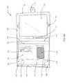
- FIGS. 2A-2Care views illustrating embodiments of a case 200 for a portable electronic device 101 .
- the case 200may be similar to the bifold case 100 .
- the case 200may comprise a first panel 110 , a device enclosure 220 , a second panel 130 , a first support stand 140 , a second support stand 150 , a panel joint 260 , and a panel latch 270 .
- the case 200is arranged in a second opened position where the first panel 110 and the second panel 130 are adjacent to each other and approximately parallel to each other.
- the device enclosure 220may be configured to enclose and selectively release a portable electronic device 101 .
- the device enclosurecomprises an enclosure fastener 221 that selectively fastens to the first panel 110 thereby securing the portable electronic device 101 within the device enclosure 120 .
- the device fastener 121may comprise any suitable fastener, including, but not limited to, a snap fastener, a hook-and-loop fastener, a hook-and-eye fastener, one or more magnets, a button, a buckle, a zipper, a tie, an adhesive, a retaining pin or clip, or the like.
- the device enclosure 220comprises one or more control windows 222 configured to allow a user access to buttons, switches, ports, and/or slots located on a portable electronic device 101 .
- the control window(s) 222are located at suitable positions on the device enclosure 220 to allow for user manipulation of the controls, ports, and/or slots of the portable electronic device 101 .
- the control window(s) 222may be modified to accommodate the various locations and dimensions of controls, ports, and/or slots, of a specific portable electronic device 101 .
- the number of control windows 222 provided in the device enclosure 220may vary according to the number and location of controls, ports, and/or slots of a specific portable electronic device 101 .
- the panel latch 270may be configured to selectively maintain the case 200 in a closed configuration and may be a specific example of the closure 170 . As seen in FIG. 2C , the panel latch 270 may be interposed between the first panel 110 and the second panel 130 so that there is a gap between the two panels. In other embodiments, the closure 170 sits flush with the first panel 110 so that there is no gap between first panel 110 and second panel 130 . The second opened position is more compact than the first opened position and the case may be more easily held in the hand by a user.
- the case 200may comprise one or more first support flap retainers 242 to selectively retain the first support flap 140 in a folded position while the case 200 is in the second opened position.
- the first support flap retainer 242applies bias to the first support flap 140 so that it remains in a folded position but can be selectively freed to rotate to the extended position.
- the case 200may also comprise one or more second support flap retainers 255 to selectively retain the second support flap 150 in a folded position while the case 200 is in the second opened position.
- the second support flap retainer 255applies bias to the second support flap 150 so that it remains in a folded position but can be selectively freed to rotate to the extended position.
- the support flap retainers 242 , 255ensure that the second opened position is a compact arrangement of the case 200 and that the support flaps 140 , 150 do not catch on surrounding objects.
- the first support flap retainer 242comprises at least one pair of magnetic devices.
- the magnetic devicesmay comprise a pair of magnets, a magnet and a corresponding ferromagnetic material (e.g., steel, iron, or nickel), or other suitable devices attracted to each other via magnetic forces.
- One magnetic device of the pairmay be located in the first support flap 140 while the other magnetic device of the pair may be located in the second panel 130 .
- the magnetic attraction between the first support flap retainers 242maintains the first support flap 140 in the folded position.
- the magnetic first support flap retainer 242is configured to interact with sensors of a portable electronic device 101 such that the change in magnetic field caused by opening the case 200 triggers the portable electronic device 101 to wake up or power up and the change in magnetic field caused by closing the case 200 triggers the portable electronic device 101 to sleep or power down.
- the first support flap retainer 242comprises at least one bistable spring having a first stable position corresponding to the folded position of the first support flap 140 and a second stable position corresponding to the extended position of the first support flap 140 .
- the bistable springattaches to the first support flap 140 and to the second panel 130 .
- the bistable springpasses through the first flap connector 141 .
- the bistable springis located adjacent to the first flap connector 141 .
- the second support flap retainer 255comprises at least one pair of magnetic devices.
- the magnetic devicesmay comprise a pair of magnets, a magnet and a corresponding ferromagnetic material (e.g., steel, iron, or nickel), or other suitable devices attracted to each other via magnetic forces.
- One magnetic device of the pairmay be located in the second support flap 150 while the other magnetic device of the pair may be located in the second panel 130 . The magnetic attraction between the magnetic devices maintains the second support flap 150 in the folded position.
- the magnetic second support flap retainer 255is located and/or configured to interact with magnetic sensors embedded in the portable electronic device 101 such that the change in magnetic field caused by opening the bifold case 100 (i.e., arranging the bifold case 100 in an opened configuration) triggers the portable electronic device 101 to wake up or power up and the change in magnetic field caused by closing the bifold case 100 (i.e., arranging the bifold case 100 in a closed configuration) triggers the portable electronic device 101 to sleep or power down.
- the second support flap retainer 255comprises at least one bistable spring having a first stable position corresponding to the folded position of the second support flap 150 and a second stable position corresponding to the extended position of the second support flap 150 .
- the bistable springattaches to the second support flap 150 and to the second panel 130 .
- the bistable springpasses through the second flap connector 151 .
- the bistable springis located adjacent to the second flap connector 151 .
- the pocket 152is most easily accessible when the case 200 is arranged in the second opened position.
- the device enclosure 220will not interfere with objects being placed into or removed from the pocket 152 .
- the card slots 153 and the ID slot 154may be easily accessible when the case 200 is arranged in the second opened position.
- FIGS. 3A and 3Bare views illustrating embodiments of an exterior portion of a case 300 for a portable electronic device.
- FIG. 3Aillustrates a perspective view of one embodiment of the case 300 arranged in a closed configuration.
- the closed position of FIG. 3Amay be conducive to the carrying or transportation of a portable electronic device (not shown).
- the portable electronic devicemay be enclosed within the case 300 and be protected from damage.
- the case 300may be similar to the cases 100 and/or 200 .
- the first panel 110 and device receptacle 120retain a portable electronic device such that the backside and edges of the portable electronic device are substantially protected.
- first panel 110comprises a camera window 111 through which a camera of a portable electronic device may capture images of scenes and/or objects exterior to the case 300 .
- the second panel 130covers a screen of a portable electronic device when the case 300 is in the closed configuration.
- the case 300 in a closed configurationmay form a compact and/or stylish carrying case for the portable electronic device.
- the case 300may be secured in the closed configuration by closure 170 which may be selectively attached to second panel 130 .
- closure 170may be selectively attached to second panel 130 .
- a usermay access controls or ports or a portable electronic device via access slot 122 .
- a usermay use access slot 122 to charge a portable electronic device while the case 300 is arranged in the closed configuration.
- FIG. 3Billustrates a view of one embodiment of an exterior of the case 300 arranged in a first open configuration.
- the case 300may comprise a first panel 110 that is permanently attached to second panel 130 by panel joint 360 .
- Panel joint 360comprises a flexible joint configured to join the first panel 110 to the second panel 130 and is a specific example of panel connector 160 .
- the panel joint 360comprises flexible material permanently attached to the first panel 110 on one side and to the second panel 130 on the opposite side.
- the panel joint 130may be formed of a variety of flexible materials including a fabric, leather, plastic, composite, or any other suitable material.
- the first panel 110 , second panel 130 , and panel joint 360are one unitary panel with a portion of the unitary panel corresponding to the first panel 110 , a portion corresponding to the second panel 130 , and a portion corresponding to the panel joint 360 .
- the unitary panelmay be formed of a variety of semi rigid materials such that the first panel 110 and second panel 130 portions provide the needed support and maintain their shape while the panel joint 360 can flex and bend into the closed and open configurations.
- the panel joint 360may be formed at one side of the first panel 110 and attached to the second panel 130 . In other embodiments, the panel joint 360 may be formed at one side of the second panel 130 and attached to the first panel 110 . In some embodiments, the first panel 110 , the second panel 130 , and the panel joint 360 comprise at least two pieces of material that share a unitary outer layer or inner layer.
- first panel 110may be connected to a second panel 130 .
- the exterior of the case 300may be formed of a variety of materials.
- the exteriormay include various materials, such as fabric, plastic, rubber, metal, leather, faux leather, vinyl, nylon, and/or any of a wide variety of alternative decorative or useful materials utilized in cases, bags, luggage, and the like.
- the exterior of the case 300may be formed of a scratch-resistant material so as to reduce scratching of the case 300 .
- Other portions of the case 300may include the same or other materials to provide a pleasing appearance to the case 300 .
- the case 300may comprise a closure 170 attached to the first panel 110 and configured to selectively maintain the case 300 in a closed configuration by selectively attaching to a corresponding receiver 370 on the second panel 130 .
- the closure 170may extend from the second panel 130 and attach to a receiver 370 on the first panel 110 .
- the closure 170 and corresponding receiver 370may comprise any suitable fasteners, including, but not limited to, snap fasteners, hook-and-loop fasteners, hook-and-eye fasteners, magnets, buttons, buckles, zippers, ties, adhesives, latches, retaining pins or clips, or the like.
- the closure 170may comprise a strap having a male snap fastener and that extends from the first panel 110 to selectively attach to the corresponding receiver 370 comprising a female snap fastener that is located on the second panel 130 . While FIG. 3B shows one strap, in other embodiments the case 300 may comprise a plurality of closures 170 that attach to a plurality of receivers 370 .
- FIGS. 4A-4Dare views of a case 400 for a portable electronic device 101 .
- the case 400may be similar to the cases 100 , 200 , and/or 300 .
- the case 400comprises a first panel 110 , a device receptacle 120 , a second panel 130 , a first support flap 140 , a second support flap 150 , a panel connector 160 , and a closure 170 .
- FIGS. 4A-4Dillustrate the case 400 having the first support flap 140 arranged in an extended position.
- FIGS. 4A and 4Billustrate the case 400 arranged in a first opened configuration while FIGS. 4C and 4D illustrate the case 400 arranged in a second open configuration.
- FIG. 4Aillustrates a top view of the case 400 which may comprise a first rotation limiter 443 configured to limit the rotation of first support flap 140 .
- the first support flap 140is attached to the second panel 130 via the first flap connector 141 .
- the first support flap 140may rotate with respect to the second panel 130 up to a maximum rotation angle defined by the first rotation limiter 443 .
- the first rotation limiter 443is adjustable, such that the maximum rotation angle may be adjusted.
- FIG. 4Ashows the first support flap 140 attached to a left portion and/or edge of the second panel, in other embodiments, the support flap 140 attaches to different portions and/or edges of the second panel 130 .
- the first support flap 140may attach to the right edge of the second panel 130 .
- the first support flap 140may attach to the upper edge (or the lower edge) of the second panel 130 .
- the first support flap 140comprises a proximal end 440 A and a distal end 440 B.
- the first support flap 140is pivotably coupled to the second panel 130 at the first support flap's proximal end 440 A.
- the first flap connector 441may secure the first support panel 140 to the second panel 130 at the first support flap's proximal end 440 A.
- the first flap connector 441may comprise a flexible joint, a mechanical hinge, or any other suitable connector such that the first support flap 140 and the second panel 130 can pivot in relation to each other.
- the distal end of the first support flap 440 Bmay be free or selectively freed from the second panel 130 to allow the second support flap to be extended.
- the first support flap 140is selectively affixed to the second panel 130 via one or more first support flap retainers 242 .
- the first rotation limiter 443comprises a strap or ribbon affixed to the first support flap 140 at one end and to the second panel 130 at the other end.
- the strap or ribbonis slack.
- the slackis taken out of the strap or ribbon until the strap or ribbon is pulled taut. The taut strap or ribbon prevents further rotation of the first support flap 140 .
- the maximum rotation angle of the first support flap 140(i.e., the maximum angle to which the first support flap can rotate) is determined by both the length of the first rotation limiter 443 and the distance between the first flap connector 141 and the attachment point of the first rotation limiter 443 .
- the first rotation limiter 443comprises a pair of flat, rigid members that are joined together at one end via a flexible joint or hinge.
- One flat memberis attached to the first support flap 140 while the other is attached to the second panel 130 .
- the flat memberslie atop each other and the angle formed between the two flat members is substantially 0°.
- the flat memberspivot around their joint, or hinge, and the angle between the flat members increases to a maximum angle of 180°. At this maximum angle, the joined flat members are fully extended. The fully extended flat members prevent further rotation of the first support flap 140 .
- the maximum rotation angle of the first support flap 140(i.e., the maximum angle to which the first support flap can rotate) is determined by both the length of the first rotation limiter 443 and the distance between the first flap connector 141 and the attachment point of the first rotation limiter 443 .
- the first rotation limiter 443is omitted because a bistable spring is used to bias the first support flap 140 in a folded position or an open position. In other embodiments, the first rotation limiter 443 acts conjunction with a bistable spring to limit the rotation of the first support flap.
- the case 400when the case 400 is arranged in the second opened configuration and the first support flap 140 is in an extended position, the case 400 may be propped up upon a supporting surface such that the ends of the first panel 110 and the second panel 130 that are opposite the panel connector 160 are elevated above the supporting surface.
- This arrangement of the case 400is referred to as the first supported position.
- the first supported positionplaces a screen of the personal electronic device 101 at a first angle 480 relative to the surface upon which the case rests.
- This first angle 480corresponds to a first viewing angle as the supported position allows a user to view the screen at the first viewing angle.
- the closure 170may be interposed between the first panel 110 and the second panel 130 so that there is a gap or space between the two panels. In other embodiments, the closure 170 sits flush with the first panel 110 so that there is no gap between first panel 110 and second panel 130 .
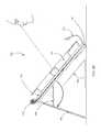
- FIGS. 5A-5Care views of a case 500 for a portable electronic device 101 .
- the case 500may be similar to the cases 100 , 200 , 300 , and/or 400 .
- the case 500comprises a first panel 110 , a device receptacle 120 , a second panel 130 , a first support flap 140 , a second support flap 150 , a panel connector 160 , and a closure 170 .
- FIGS. 5A-5Cillustrate the case 500 having the second support flap 150 arranged in an extended position.
- FIG. 5Ais a perspective view of the case 500 arranged in a first opened configuration.
- FIGS. 5B-5Care a perspective and a side view, respectively, of the case 500 in a second opened configuration.
- FIG. 5Ais a top view of case 500 which may comprise a second rotation limiter 556 configured to limit the rotation of second support flap 150 .
- the second support flap 150is attached to the second panel 130 via the second flap connector 151 .
- the second support flap 150may rotate with respect to the second panel 130 up to a maximum rotation angle defined by the second rotation limiter 556 .
- the second rotation limiter 556is adjustable, such that the maximum rotation angle may be adjusted.
- FIG. 5Ashows the second support panel 150 attached to a right portion and/or edge of the second panel 130
- the support flap 150attaches to different portions and/or edges of the second panel 130 .
- the second support flap 150may attach to the left edge of the second panel 130 .
- the second support flap 150may attach to the lower edge (or to the upper edge) of the second panel 130 .
- the second support flap 150comprises a proximal end 550 A and a distal end 550 B.
- the second support flap 150is pivotably coupled to the second panel 130 at the at the second support flap's proximal end 550 A.
- the second flap connector 151may secure the second support flap 150 to the second panel 130 at the second support flap's proximal end 550 A.
- the second flap connectormay comprise a flexible joint, a mechanical hinge, or any other suitable connector.
- the second flap connectormay be made from a fabric, leather, a hinge, or another material or mechanism such that the second support flap 150 and the second panel 130 can pivot in relation to each other.
- the distal end of the second support flap 550 Bmay be free or selectively freed from the second panel 130 to allow the second support flap to be extended.
- Second support flap 150may be selectively affixed to the second panel 130 via one or more second support flap retainers 255 .
- the second rotation limiter 556comprises a strap or ribbon affixed to the second support flap 150 at one end and to the second panel 130 at the other end.
- the strap or ribbonis slack.
- the slackis taken out of the strap or ribbon until the strap or ribbon is pulled taut. The taut strap or ribbon prevents further rotation of the second support flap 150 .
- the maximum rotation angle of the second support flap 150(i.e., the maximum angle to which the second support flap 150 can rotate) is determined by both the length of the second rotation limiter 556 and the distance between the second flap connector 151 and the attachment point of the second rotation limiter 556 .
- the second rotation limiter 556comprises a strap whose length can be adjusted. By adjusting the length of the strap, a user can vary the maximum rotation angle that the second support flap 150 can rotate.
- the second viewing angleis related to the length of the second support flap 150 and its maximum rotation angle according to the principles of trigonometry. Thus, when the maximum rotation angle of the second support flap is changed, the second viewing angle is also changed.
- the second rotation limiter 556comprises a pair of flat, rigid members that are joined together at one end via a flexible joint or hinge.
- One flat memberis attached to the second support flap 150 while the other is attached to the second panel 130 .
- the flat memberslie atop each other and the angle formed between the two flat members is substantially 0°.
- the flat memberspivot around their joint, or hinge, and the angle between the flat members increases to a maximum angle of 180°. At this maximum angle, the joined flat members are fully extended, thereby preventing further rotation of the second support flap 150 .
- the maximum rotation angle of the second support flap 150(i.e., the maximum angle to which the second support flap can rotate) is determined by both length of the second rotation limiter 556 and the distance between the second flap connector 151 and the attachment point of the second rotation limiter 556 .
- the second rotation limiter 556is omitted because a bistable spring is used to bias the second support flap 150 in a folded position or an open position. In other embodiments, the second rotation limiter 556 acts conjunction with a bistable spring to limit the rotation of the second support flap 150 .
- the case 500when the case 500 is arranged in the second opened configuration and the second support flap 150 is in an extended position, the case 500 may be propped up upon a supporting surface such that the ends of the first panel 110 and the second panel 130 that are attached to the panel connector 160 are elevated above the supporting surface.
- This arrangement of the case 500is referred to as the second supported position.
- the second supported positionplaces a screen of the personal electronic device 101 at a second angle 580 relative to the surface upon which the case rests.
- This second angle 580corresponds to a second viewing angle as the supported position allows a user to view the screen at the second viewing angle.
- the closure 170may be interposed between the first panel 110 and the second panel 130 so that there is a gap or space between the two panels. In other embodiments, the closure 170 sits flush with the first panel 110 so that there is no gap between first panel 110 and second panel 130 .
- FIGS. 6A-6Care views of a case 600 for a portable electronic device 101 .
- the case 600comprises a first panel 110 , a device receptacle 120 , a second panel 130 , a first support flap 140 , an angled support flap 650 , a panel connector 160 , and a closure 170 .
- FIG. 6Ais a top view of an embodiment of case 600 in a second opened configuration
- FIGS. 6B and 6Care perspective views of embodiments of case 600 in a second opened configuration.
- the angled support flap 650may replace the second support flap on the second panel 130 .
- the angled support flap 650is pivotably coupled to the second panel 130 via the angled flap connector 551 .
- the angled flap connector 551may comprise a flexible joint, a mechanical hinge, or any other suitable connector.
- the angled flap connector 551may be made from a fabric, leather, a hinge, or another material or mechanism such that the angled support flap 650 and the second panel 130 can pivot in relation to each other.
- a distal end of the angled support flap 650 opposite the angled flap connector 551may be free or selectively freed from the second panel 130 to allow the angled support flap 650 to be extended.
- the angled support flap 650may be selectively affixed to the second panel 130 via one or more angled support flap retainers 655 . While FIG. 6A shows the first support flap 140 attached to a bottom portion and/or edge, and the angled support panel 650 attached to an upper-left bottom portion and/or corner, of the second panel, in other embodiments, the support flaps 140 , 650 attach to different portions of the second panel 130 . For example, the first support flap 140 may attach to the upper, right, or left edges of the second panel 130 . As another example, the angled support flap 650 may attach at the upper-right, lower-right, or lower-left corners of the second panel 130 .
- the first support flap 140 and the angled support flap 650attach to the second panel 130 such that the first support flap 140 and the angled support flap 650 may each rotate with respect to the second panel 130 .
- the axis of rotation of the first support flap 140may be at an acute angle relative to the axis of rotation of the angled support flap 650 .
- the angled flap connector 651may be positioned at an angle relative to the first flap connector 141 .
- the angled flap connector 651allows the case to be elevated in both a landscape orientation (see FIG. 6B ) and a portrait orientation (see FIG. 6C ).
- the different orientations of FIG. 6B and FIG. 6Cmay allow for a user to select a preferred orientation for a current task, such as reading, watching video, typing using a virtual keyboard, typing using a separate physical keyboard, or other task.
- the case 600may comprise a third rotation limiter 656 configured to limit the rotation of angled support flap 650 .
- the angled support flap 650may rotate with respect to the second panel 130 up to a maximum rotation angle defined by the third rotation limiter 656 .
- FIGS. 6B and 6Cillustrate the case 600 having the angled support flap 650 arranged in an extended position.
- the third rotation limiter 656is adjustable, such that the maximum rotation angle may be adjusted.
- the third rotation limiter 656comprises a strap or ribbon affixed to the angled support flap 650 at one end and to the second panel 130 at the other end.
- the strap or ribbonis slack.
- the slackis taken out of the strap or ribbon until the strap or ribbon is pulled taut. The taut strap or ribbon prevents further rotation of the angled support flap 650 .
- the maximum rotation angle of the angled support flap 650(i.e., the maximum angle to which the angled support flap 650 can rotate) is determined by both the length of the third rotation limiter 656 and the distance between the angled flap connector 551 and the attachment point of the third rotation limiter 656 .
- the third rotation limiter 656comprises a strap whose length can be adjusted. By adjusting the length of the strap, a user can vary the maximum rotation angle that the angled support flap 650 can rotate.
- the second viewing angleis related to the length of the angled support flap 650 and its maximum rotation angle according to the principles of trigonometry. Thus, when the maximum rotation angle of the second support flap is changed, the second viewing angle is also changed.
- the third rotation limiter 656comprises a pair of flat, rigid members that are joined together at one end via a flexible joint or hinge.
- One flat memberis attached to the angled support flap 650 while the other is attached to the second panel 130 .
- the flat memberslie atop each other and the angle formed between the two flat members is substantially 0°.
- the flat memberspivot around their joint, or hinge, and the angle between the flat members increases to a maximum angle of 180°. At this maximum angle, the joined flat members are fully extended, thereby preventing further rotation of the angled support flap 650 .
- the maximum rotation angle of the angled support flap 650(i.e., the maximum angle to which the second support flap can rotate) is determined by both length of the third rotation limiter 656 and the distance between the angled flap connector 551 and the attachment point of the third rotation limiter 656 .
- the case 600may comprise one or more angled support flap retainers 655 to retain the angled support flap 650 in a folded position while the case 600 is in a second opened position (e.g., where the first panel 110 and the second panel 130 are adjacent to each other and approximately parallel to each other).
- the angled support flap retainer 655applies bias to the angled support flap 650 so that it remains in a folded position but can be selectively freed to rotate to the extended position.
- the angled support flap retainers 655ensure that the second opened position is a compact arrangement of the case 600 and that the angled support flap 650 does not catch on surrounding objects.
- the angled support flap retainer 655comprises at least one pair of magnetic devices.
- the magnetic devicesmay comprise a pair of magnets, a magnet and a corresponding ferromagnetic material (e.g., steel, iron, or nickel), or other suitable devices attracted to each other via magnetic forces.
- One magnetic device of the pairmay be located in the angled support flap 650 while the other magnetic device of the pair may be located in the second panel 130 .
- the magnetic attraction between the angled support flap retainers 655maintains the angled support flap 650 in the folded position.
- the magnetic angled support flap retainer 655is configured to interact with one or more sensors of a portable electronic device 101 such that the change in magnetic field caused by opening the case 600 triggers the portable electronic device 101 to wake up or power up and the change in magnetic field caused by closing the case 600 triggers the portable electronic device 101 to sleep or power down.
- the angled support flap retainer 655comprises at least one bistable spring having a first stable position corresponding to the folded position of the angled support flap 650 and a second stable position corresponding to the extended position of the angled support flap 650 .
- the bistable springattaches to the angled support flap 650 and to the second panel 130 .
- the bistable springpasses through the angled flap connector 551 .
- the bistable springis located adjacent to the angled flap connector 551 .
- the third rotation limiter 656is omitted because a bistable spring is used to bias the angled support flap 650 in a folded position or an open position. In other embodiments, the third rotation limiter 656 acts conjunction with a bistable spring to limit the rotation of the angled support flap 650 .
- the case 600when the case 600 is arranged in the second opened configuration and the angled support flap 650 is in an extended position, the case 600 may be propped up upon a supporting surface such that the ends of the first panel 110 and the second panel 130 that are attached to the panel connector 160 are elevated above the supporting surface.
- the casemay be selectively arranged in a landscape supported position (see FIG. 6B ) and a portrait supported position (see FIG. 6C ).
- the landscape supported positionplaces a screen of the personal electronic device 101 at a third angle 680 relative to the surface upon which the case rests. This third angle 680 corresponds to a third viewing angle as the landscape supported position allows a user to view the screen at the third viewing angle.
- the portrait supported positionplaces a screen of the personal electronic device 101 at a fourth angle 680 relative to the surface upon which the case rests.
- This fourth angle 680corresponds to a fourth viewing angle as the portrait supported position allows a user to view the screen at the fourth viewing angle.
- the different angles of FIGS. 6B and 6Cmay allow for a user to select a preferred angle for a current task, such as reading, watching video, typing using a virtual keyboard, typing using a separate physical keyboard, or other task.
- angled support flap 650may comprise one or more receptacles configured to receive flat items.
- the receptaclesmay comprise card slots 153 and an ID slot 154 .
- the card slots 153may comprise slots or pockets located in the angled support panel 650 and configured to hold credit cards or similarly shaped objects.
- the ID slot 154comprises a windowed card holder located on angled support panel 650 and is configured to hold an identification card or the like.
- a second ID slot 154is provided in lieu of the one or more card slots 153 and vice versa.
- One of skill in the artwill recognize considerable variation within the scope of the present disclosure regarding how a various pockets, card slots, and ID slots may be arranged on the angled support flap 650 .
- the angled support flap 650may be rigid or semi-rigid to maintain its shape.
- a rigid or semi-rigid angled support flap 650retains its planar shape and supports the case 600 and/or second panel 130 when the case 600 is configured in a landscape or a portrait supported position.
- the angled support flap 650is extremely flexible it may not hold its shape enough to support the case 600 and/or portable electronic device 101 in the supported positions depicted in FIGS. 6B and 6C .
- the angled support flap 650may be formed of a variety of materials including a fabric, leather, plastic, composite, metal, or any other material.
- an outer portion of the angled support flap 650may be formed of a soft or protective material to reduce scratching of a portable electronic device 101 .
- a surface of the angled support flap 650 that faces the device receptacle 120 when the case 600 is in a closed configurationmay be formed of a soft fabric, lint free cloth, suede leather or imitation suede leather, or the like.
- Other portions of the angled support flap 650may include the same or other materials to provide a pleasing appearance to the case 600 .
- the angled support flap 650may be formed of rigid or semi-rigid material such that the angled support flap 650 maintains its planar shape.
- a portion of the angled support flap 650may be formed of a variety of rigid or semi-rigid materials including a fabric, leather, plastic, composite, metal, or any other suitable material.
- Other portions of the angled support flap 650may include the same or other materials to provide a pleasing appearance to the bifold case 100 .
- the terms “comprises,” “comprising,” and any other variation thereof,are intended to cover a non-exclusive inclusion, such that a process, a method, an article, or an apparatus that comprises a list of elements does not include only those elements but may include other elements not expressly listed or inherent to such process, method, system, article, or apparatus.
Landscapes
- Engineering & Computer Science (AREA)
- Mechanical Engineering (AREA)
- Casings For Electric Apparatus (AREA)
- Telephone Set Structure (AREA)
Abstract
Description
Claims (22)
Priority Applications (1)
| Application Number | Priority Date | Filing Date | Title |
|---|---|---|---|
| US13/747,992US8763795B1 (en) | 2013-01-23 | 2013-01-23 | Dual support flap case |
Applications Claiming Priority (1)
| Application Number | Priority Date | Filing Date | Title |
|---|---|---|---|
| US13/747,992US8763795B1 (en) | 2013-01-23 | 2013-01-23 | Dual support flap case |
Publications (2)
| Publication Number | Publication Date |
|---|---|
| US8763795B1true US8763795B1 (en) | 2014-07-01 |
| US20140202890A1 US20140202890A1 (en) | 2014-07-24 |
Family
ID=50981939
Family Applications (1)
| Application Number | Title | Priority Date | Filing Date |
|---|---|---|---|
| US13/747,992Expired - Fee RelatedUS8763795B1 (en) | 2013-01-23 | 2013-01-23 | Dual support flap case |
Country Status (1)
| Country | Link |
|---|---|
| US (1) | US8763795B1 (en) |
Cited By (145)
| Publication number | Priority date | Publication date | Assignee | Title |
|---|---|---|---|---|
| US20140071606A1 (en)* | 2012-09-11 | 2014-03-13 | Logitech Europe S.A. | Protective Cover for a Tablet Computer |
| US20140104761A1 (en)* | 2012-10-11 | 2014-04-17 | Fu-Yi Hsu | Protective sheath |
| US20140202891A1 (en)* | 2012-11-20 | 2014-07-24 | Speculative Product Design, Llc | Folio case for a portable electronic device with inlaid fabric |
| US20140238876A1 (en)* | 2013-02-26 | 2014-08-28 | Superior Communications, Inc. | Folio case |
| US20140262934A1 (en)* | 2013-03-15 | 2014-09-18 | Incipio Technologies, Inc. | Case for mobile device |
| US20140333542A1 (en)* | 2013-05-10 | 2014-11-13 | Research In Motion Limited | Carrying case used with a portable electronic device |
| USD718769S1 (en)* | 2013-11-19 | 2014-12-02 | Peter N Bassil | Tablet case |
| USD718768S1 (en)* | 2013-05-08 | 2014-12-02 | Oliver Page | Cross strap case for electronic computer |
| USD719169S1 (en)* | 2013-07-31 | 2014-12-09 | Brian Dale McBroom | Tablet keyboard cover |
| USD721081S1 (en)* | 2014-05-14 | 2015-01-13 | Marvelpress Limited | Tablet personal computer flip case |
| USD721080S1 (en)* | 2014-02-21 | 2015-01-13 | Amazon Technologies, Inc. | Electronic device cover |
| US20150015777A1 (en)* | 2013-07-09 | 2015-01-15 | Lenovo (Singapore) Pte. Ltd. | Control flap |
| USD722059S1 (en)* | 2014-05-07 | 2015-02-03 | Marvelpress Limited | Tablet personal computer flip case |
| USD723041S1 (en)* | 2014-03-31 | 2015-02-24 | Samsung Electronics Co., Ltd. | Cover for electronic device |
| USD723037S1 (en)* | 2013-09-24 | 2015-02-24 | Triangus Group Co., Ltd. | Tablet computer case |
| USD723040S1 (en)* | 2013-12-17 | 2015-02-24 | Aevoe International Ltd. | Tablet computer case |
| US20150054273A1 (en)* | 2013-08-23 | 2015-02-26 | ACCO Brands Corporation | Component with Display Stand |
| USD723569S1 (en)* | 2013-12-10 | 2015-03-03 | Hon Hai Precision Industry Co., Ltd. | Cover for portable electronic device |
| USD723568S1 (en)* | 2013-08-12 | 2015-03-03 | Samsung Electronics Co., Ltd. | Cover for mobile communication terminal |
| USD724090S1 (en)* | 2013-08-12 | 2015-03-10 | Samsung Electronics Co., Ltd. | Cover for mobile communication terminal |
| USD724095S1 (en)* | 2014-03-31 | 2015-03-10 | Samsung Electronics Co., Ltd. | Cover for electronic device |
| USD725118S1 (en)* | 2014-04-15 | 2015-03-24 | Hewlett-Packard Development Company, L.P. | Soft cover for mobile PC |
| USD725659S1 (en)* | 2013-06-25 | 2015-03-31 | Kevin Alan Tussy | Mobile device case |
| USD726193S1 (en)* | 2014-04-29 | 2015-04-07 | Samsung Electronics Co., Ltd. | Case for electronic device |
| USD726191S1 (en)* | 2014-01-28 | 2015-04-07 | Asustek Computer Inc. | Cover |
| USD726192S1 (en)* | 2014-06-25 | 2015-04-07 | Htc Corporation | Foldable front cover for electronic device |
| USD726731S1 (en)* | 2014-03-31 | 2015-04-14 | Samsung Electronics Co., Ltd. | Cover for electronic device |
| US20150108188A1 (en)* | 2013-10-21 | 2015-04-23 | Select Comfort Corporation | Tablet or Laptop Support Cushion |
| US20150111624A1 (en)* | 2013-10-18 | 2015-04-23 | Douglas Peel | Dual holding case for computing devices |
| USD727916S1 (en)* | 2014-01-07 | 2015-04-28 | TouchFire, Inc. | Protective case |
| USD727919S1 (en)* | 2014-06-09 | 2015-04-28 | TouchFire, Inc. | Protective case |
| USD727915S1 (en)* | 2013-09-20 | 2015-04-28 | Amazon Technologies, Inc. | Electronic device cover |
| USD728579S1 (en)* | 2013-09-20 | 2015-05-05 | Amazon Technologies, Inc. | Electronic device cover |
| USD729253S1 (en)* | 2013-07-01 | 2015-05-12 | STM Management Pty Ltd. | Case for a tablet computer |
| USD730913S1 (en)* | 2014-03-11 | 2015-06-02 | Aevoe International Ltd. | Tablet computer sleeve |
| US9049911B1 (en)* | 2013-09-23 | 2015-06-09 | Amazon Technologies, Inc. | Electronic device cover |
| USD731495S1 (en)* | 2014-01-07 | 2015-06-09 | Thule Organization Solutions, Inc. | Protective case for an electronic device |
| US9065932B2 (en) | 2013-05-10 | 2015-06-23 | Blackberry Limited | Device for providing notifications while mated with a carrying case |
| USD732542S1 (en)* | 2014-01-07 | 2015-06-23 | Thule Organization Solutions, Inc. | Protective cover for an electronic device |
| USD733152S1 (en)* | 2014-03-24 | 2015-06-30 | World Richman Manufacturing Corporation | Reversible case for mobile communications device |
| USD733150S1 (en)* | 2014-03-22 | 2015-06-30 | World Richman Manufacturing Corporation | Reversible case for mobile communications device with rotatable device-holding cradle |
| USD733154S1 (en)* | 2014-08-20 | 2015-06-30 | Urban Armor Gear LLC | Tablet computer case |
| USD733151S1 (en)* | 2014-03-23 | 2015-06-30 | Malcolm Brierley | Case for an E-reader device with viewing stand and a ‘Y’ shaped ergonomic hand strap |
| USD733714S1 (en)* | 2013-12-20 | 2015-07-07 | Pelican Products, Inc. | Case for electronic pad |
| USD734340S1 (en)* | 2014-04-29 | 2015-07-14 | Samsung Electronics Co., Ltd. | Case for electronic device |
| USD734761S1 (en)* | 2013-12-20 | 2015-07-21 | Pelican Products, Inc. | Case for electronic pad |
| US9095194B2 (en) | 2012-12-12 | 2015-08-04 | Thule Organization Solutions, Inc. | Protective case for an electronic device |
| USD737276S1 (en)* | 2013-09-20 | 2015-08-25 | Urban Armor Gear, Llc | Protective case for electronic tablet |
| USD737827S1 (en)* | 2013-08-28 | 2015-09-01 | Fih (Hong Kong) Limited | Protecting enclosure for portable electronic device |
| USD737828S1 (en)* | 2014-02-25 | 2015-09-01 | Stephen J. Albano | Personal organizer folder |
| USD740882S1 (en)* | 2012-12-20 | 2015-10-13 | Thule Organization Solutions, Inc. | Protective case |
| USD741867S1 (en)* | 2013-01-31 | 2015-10-27 | GoDirectInc.com, Inc. | Compact tablet computer case |
| USD743406S1 (en)* | 2014-09-15 | 2015-11-17 | Amazon Technologies, Inc. | Tablet device case |
| USD743967S1 (en)* | 2014-10-15 | 2015-11-24 | Triangus Group Co., Ltd. | Tablet computer case |
| USD744492S1 (en)* | 2014-08-18 | 2015-12-01 | Ozaki International Co., Ltd | Combination of protection cover and keyboard |
| USD744490S1 (en)* | 2014-10-21 | 2015-12-01 | Logitech Europe S.A. | Protective folio for multiple types of input devices |
| USD744489S1 (en)* | 2014-08-23 | 2015-12-01 | World Richman Manufacturing Corporation | Cradle-case combination for an electronic device |
| USD744491S1 (en)* | 2014-11-10 | 2015-12-01 | Logitech Europe S.A. | Adjustable protective cover for an input device |
| USD745013S1 (en)* | 2014-03-24 | 2015-12-08 | Malcolm Brierley | Case for an E-reader device with viewing stand and hand strap |
| USD745525S1 (en)* | 2014-09-08 | 2015-12-15 | Logitech Europe S.A. | Protective folio for an input device |
| US20160007484A1 (en)* | 2013-08-15 | 2016-01-07 | Charles Augustus Daley, III | Bag computer display panel improvements |
| US20160021766A1 (en)* | 2014-07-15 | 2016-01-21 | Vikramaditya Jain | Dual portable electronic device carrying case |
| USD748097S1 (en)* | 2014-07-25 | 2016-01-26 | Youru Feng | Tablet case |
| USD749078S1 (en)* | 2013-05-07 | 2016-02-09 | Antenna79, Inc. | Tablet cover |
| USD750089S1 (en) | 2015-08-17 | 2016-02-23 | FLB Group Limited | Tablet computer stand |
| USD750632S1 (en)* | 2011-03-17 | 2016-03-01 | Incase Designs Corp. | Cover for electronic tablet |
| US20160088749A1 (en)* | 2014-09-19 | 2016-03-24 | Wistron Corp. | Electronic device and stand thereof |
| US9298216B1 (en) | 2013-09-23 | 2016-03-29 | Amazon Technologies, Inc. | Electronic device cover with device activating mechanism |
| USD752593S1 (en)* | 2011-03-17 | 2016-03-29 | Incase Designs Corp. | Cover for electronic tablet |
| USD753125S1 (en)* | 2014-10-21 | 2016-04-05 | Logitech Europe S.A. | Protective folio with keyboard for multiple types of input devices |
| USD754666S1 (en)* | 2014-12-31 | 2016-04-26 | The Tiffen Company, Llc | Case for image-taking device |
| USD754643S1 (en)* | 2013-09-27 | 2016-04-26 | Samsung Electronics Co., Ltd. | Cover for electronic device with display |
| US9326404B1 (en) | 2013-09-23 | 2016-04-26 | Amazon Technologies, Inc. | Electronic device cover |
| USD756364S1 (en)* | 2014-04-11 | 2016-05-17 | Hewlett-Packard Development Company, L.P. | Tablet cover |
| US9382033B2 (en) | 2011-12-22 | 2016-07-05 | Thule Organization Solutions, Inc. | Protective case for an electronic device |
| US9389641B2 (en) | 2013-05-10 | 2016-07-12 | Blackberry Limited | Carrying case with peek functionality |
| USD762204S1 (en) | 2015-02-26 | 2016-07-26 | Urban Armor Gear, Llc | Wireless device case |
| USD762218S1 (en)* | 2014-03-28 | 2016-07-26 | World Richman Manufacturing Corporation | Reversible case for mobile communications device with universal device-holding mechanism |
| USD762630S1 (en)* | 2013-09-26 | 2016-08-02 | Samsung Electronics Co., Ltd. | Cover for electronic device with display |
| USD763839S1 (en)* | 2013-09-27 | 2016-08-16 | Samsung Electronics Co., Ltd. | Cover for electronic device with display |
| USD764472S1 (en)* | 2015-01-05 | 2016-08-23 | Logitech Europe S.A. | Protective case and cover for a mobile display device |
| USD764473S1 (en)* | 2015-04-01 | 2016-08-23 | Incipio, Llc | Device case |
| USD765663S1 (en)* | 2015-05-27 | 2016-09-06 | Asustek Computer Inc. | Protective cover for a portable electronic device |
| USD766249S1 (en) | 2015-08-05 | 2016-09-13 | Urban Armor Gear, Llc | Case for a computing device |
| USD766885S1 (en) | 2015-02-09 | 2016-09-20 | Urban Armor Gear, Llc | Wireless device case |
| USD766907S1 (en) | 2015-08-05 | 2016-09-20 | Urban Armor Gear, Llc | Case for a computing device |
| USD768123S1 (en) | 2015-02-09 | 2016-10-04 | Urban Armor Gear, Llc | Wireless device case |
| USD770457S1 (en)* | 2014-06-25 | 2016-11-01 | Htc Corporation | Foldable cover for electronic device |
| USD771030S1 (en) | 2013-01-09 | 2016-11-08 | Kevin Alan Tussy | Mobile telephone case |
| USD772880S1 (en)* | 2015-01-05 | 2016-11-29 | Logitec Europe S.A. | Protective case and support for a mobile display device |
| US9675148B2 (en) | 2015-03-18 | 2017-06-13 | Targus International Llc | Extendable, universal case for portable electronic devices |
| USD791754S1 (en) | 2014-08-20 | 2017-07-11 | Urban Armor Gear, Llc | Case for a mobile communications device |
| US20170197681A1 (en)* | 2014-11-06 | 2017-07-13 | Bayerische Motoren Werke Aktiengesellschaft | Anti-Oscillating Luggage System |
| US9762280B1 (en)* | 2014-12-11 | 2017-09-12 | Jordan C. Munn | Portable mobile phone holders and methods for operating at least two mobile phones |
| USD806378S1 (en)* | 2015-10-13 | 2018-01-02 | Uniluv Marketing Inc. | Case |
| US9874260B2 (en) | 2013-12-02 | 2018-01-23 | Otter Products, Llc | Case with integrated stand activated by pressure |
| US20180109279A1 (en)* | 2016-10-14 | 2018-04-19 | Kapil Rana | Portfolio case for use with tablet computer |
| USD817962S1 (en)* | 2017-03-02 | 2018-05-15 | Logitech Europe S.A. | Protective cover for a tablet computer |
| USD822989S1 (en)* | 2016-03-29 | 2018-07-17 | Carlobolaget Ab | Combined credit card and mobile phone holder |
| USD831654S1 (en)* | 2015-12-03 | 2018-10-23 | Avision Inc. | Scanner |
| USD839257S1 (en) | 2017-05-10 | 2019-01-29 | Derrick Polseno, SR. | Cell phone case |
| USD847804S1 (en) | 2017-05-10 | 2019-05-07 | Swyvz, Llc. | Cell phone case |
| USD851405S1 (en) | 2019-02-01 | 2019-06-18 | R.D.S. Industries, Inc. | Adjustable viewing stand for a carrying case |
| US10353427B1 (en) | 2017-04-30 | 2019-07-16 | William Rabb | Carrying case for a laptop computer |
| US20190227592A1 (en)* | 2018-01-22 | 2019-07-25 | Pioneer Square Brands, Inc. | Portable electronic device case |
| USD863312S1 (en)* | 2013-01-31 | 2019-10-15 | GoDirectInc.com, Inc. | Tablet computer case comprised of an exterior cover and detachable case |
| US10702033B1 (en) | 2018-12-27 | 2020-07-07 | R.D.S. Industries, Inc. | Carrying case with adjustable viewing stand |
| USD893498S1 (en) | 2019-01-09 | 2020-08-18 | Urban Armor Gear, Llc | Case for a computing device |
| US10782732B2 (en)* | 2013-09-21 | 2020-09-22 | Otter Products, Llc | Mounting system for electronic device |
| US10884453B2 (en) | 2015-10-09 | 2021-01-05 | Urban Armor Gear, Llc | Protective case for a computing device and method of use |
| US10928854B1 (en)* | 2018-04-06 | 2021-02-23 | Pioneer Square Brands, Inc. | Portable electronic device case |
| US10973293B2 (en) | 2013-08-15 | 2021-04-13 | Urban Armor Gear, Llc | Composite protective case for phones, other portable electronic devices and other apparatus |
| USD928788S1 (en)* | 2019-08-16 | 2021-08-24 | Samsung Electronics Co., Ltd. | Case for electronic device |
| USD934863S1 (en)* | 2018-11-20 | 2021-11-02 | Shamak LLC | Laptop case with pocket and pen holder |
| USRE48866E1 (en) | 2015-08-14 | 2021-12-28 | Urban Armor Gear, Llc | Protective case for a computing device with adjustable stand |
| USD941824S1 (en)* | 2019-08-16 | 2022-01-25 | Samsung Electronics Co., Ltd. | Case for electronic device |
| USD942459S1 (en)* | 2012-03-06 | 2022-02-01 | Apple Inc. | Case for portable display device |
| USD943589S1 (en)* | 2020-06-22 | 2022-02-15 | Jumei He | Ipad leather case |
| USD949867S1 (en)* | 2021-06-08 | 2022-04-26 | Shenzhen Huaruixin Trading Co., Ltd. | Tablet case |
| US11337498B2 (en) | 2019-01-17 | 2022-05-24 | Dango Products, Llc | Wallet with card holding mechanisms |
| US11388970B2 (en)* | 2017-11-03 | 2022-07-19 | Joseph Gordon | Portable computer case with integrated storage features |
| USD958796S1 (en)* | 2020-07-30 | 2022-07-26 | James Dalton | Articulated light transmitting cover |
| US11425976B1 (en) | 2021-09-29 | 2022-08-30 | Dango Products, Llc | Money clip |
| US11460884B2 (en) | 2019-01-24 | 2022-10-04 | Byrdbyte Creations Inc. | Case for portable computing devices |
| US20220312917A1 (en)* | 2020-07-30 | 2022-10-06 | James Dalton | Articulated Light Transmitting Transparent Cover Apparatus |
| USD976912S1 (en)* | 2020-11-27 | 2023-01-31 | Wei Yan | Case for a tablet computer |
| USD982314S1 (en) | 2021-04-09 | 2023-04-04 | Dango Products, Llc | Wallet |
| USD982315S1 (en) | 2021-04-09 | 2023-04-04 | Dango Products, Llc | Wallet |
| US11653729B2 (en) | 2019-10-22 | 2023-05-23 | Dango Products, Llc | Wallet with card holding mechanisms |
| USD987647S1 (en)* | 2021-03-12 | 2023-05-30 | Huawei Technologies Co., Ltd. | Keyboard leather sheath |
| USD987643S1 (en)* | 2021-02-10 | 2023-05-30 | Huawei Technologies Co., Ltd. | Keyboard cover |
| USD987645S1 (en)* | 2021-02-10 | 2023-05-30 | Huawei Technologies Co., Ltd. | Keyboard cover |
| US20230225473A1 (en)* | 2022-01-14 | 2023-07-20 | Jeffrey Lietzke | Mobile Device Case |
| US11737531B2 (en) | 2019-10-22 | 2023-08-29 | Dango Products, Llc | Wallet |
| USD1000170S1 (en)* | 2022-12-02 | 2023-10-03 | Guangzhou Fengyu Trading Co., Ltd. | Bible display case |
| US11786018B2 (en) | 2019-01-17 | 2023-10-17 | Dango Products, Llc | Wallet |
| US11903466B2 (en) | 2019-01-17 | 2024-02-20 | Dango Products, Llc | Wallet with card holding mechanisms |
| USD1031495S1 (en) | 2021-09-03 | 2024-06-18 | Dango Products, Llc | Money clip |
| WO2024133558A1 (en)* | 2022-12-20 | 2024-06-27 | Ipassco Gmbh | Bag for releasably fastening to a vehicle seat part or to a trolley suitcase |
| USD1044125S1 (en) | 2021-09-24 | 2024-09-24 | Conair Llc | Mirror |
| US12168552B2 (en)* | 2022-05-31 | 2024-12-17 | Logitech Europe S.A. | Packaging for an input device |
| US12294404B1 (en)* | 2022-10-18 | 2025-05-06 | Arrotech Group Llc | Protective case for portable electronic devices |
| USD1088516S1 (en) | 2022-08-12 | 2025-08-19 | Ctb Holdings Llc | Wallet |
| USD1093890S1 (en)* | 2022-10-13 | 2025-09-23 | New Things Holding B.V. | Whiteboard wallet for making notes and storing credit cards |
| US12440010B2 (en) | 2023-09-20 | 2025-10-14 | Ctb Holdings Llc | Wallet |
Families Citing this family (4)
| Publication number | Priority date | Publication date | Assignee | Title |
|---|---|---|---|---|
| CN105686287A (en)* | 2016-01-18 | 2016-06-22 | 杜德成 | Notebook computer protective cover |
| CN105476235A (en)* | 2016-01-18 | 2016-04-13 | 杜德成 | Notebook computer protection cover |
| US10694630B2 (en)* | 2017-05-10 | 2020-06-23 | Tech 21 Licensing Limited | Case for a mobile communications device with a screen |
| TWI864967B (en)* | 2022-11-07 | 2024-12-01 | 愛進化科技股份有限公司 | Container for containing food or liquid and attachment and lid thereof |
Citations (366)
| Publication number | Priority date | Publication date | Assignee | Title |
|---|---|---|---|---|
| US910619A (en) | 1908-06-09 | 1909-01-26 | Adolph Raudnitz Co | Hand-bag and the like. |
| US1046843A (en) | 1912-01-19 | 1912-12-10 | Firm Of Moriz Hausch | Lady's hand-bag. |
| US1121422A (en) | 1912-03-02 | 1914-12-15 | Thomas J Tydings | Folding type-writer cabinet. |
| GB146601A (en) | 1919-04-07 | 1920-07-07 | Alfred Astley | Improved device for the packing of bottles or articles of a similar nature |
| US1372126A (en) | 1921-03-22 | William k | ||
| US1374126A (en) | 1920-10-12 | 1921-04-05 | Walter Horace Everett | Handbag-handle |
| GB161117A (en) | 1920-08-21 | 1921-04-07 | Frederick Sanders Lakeman | Improvements in or relating to trunks, suit cases, and the like |
| US1416465A (en) | 1920-06-07 | 1922-05-16 | Harvey William Frank | Display box |
| US1444112A (en) | 1921-12-31 | 1923-02-06 | Davis Herman | Trunk |
| US1556352A (en) | 1925-01-16 | 1925-10-06 | Ritter Jacob | Bag |
| US1658174A (en) | 1926-11-19 | 1928-02-07 | Howard W Russell | Handle for containers |
| US1721427A (en) | 1926-11-22 | 1929-07-16 | Wubco Battery Corp | Container |
| US1826976A (en) | 1930-10-07 | 1931-10-13 | Wright David Edward | Traveling bag |
| US1889765A (en) | 1928-05-15 | 1932-12-06 | Travelers Efficiency Case Co I | Combination traveling case and portfolio |
| US2018605A (en) | 1933-02-20 | 1935-10-22 | Philadelphia Storage Battery | Means for packing articles within packing boxes |
| US2083029A (en) | 1937-04-15 | 1937-06-08 | Lowy Edward | Handbag |
| US2110163A (en) | 1937-09-16 | 1938-03-08 | Lobel Rudolph | Handbag |
| US2170841A (en) | 1938-05-23 | 1939-08-29 | Thies Harry August | Interchangeable utility bag |
| US2181587A (en) | 1938-04-02 | 1939-11-28 | Dresner & Son Inc S | Partition for luggage |
| US2316328A (en) | 1941-06-04 | 1943-04-13 | Henry J Guenther | Side pocket for brief cases and the like |
| US2335779A (en) | 1943-06-20 | 1943-11-30 | Mazzel Alberto | Safety carrier for nitroglycerin or other explosives |
| US2503746A (en) | 1949-03-21 | 1950-04-11 | Klehr Samuel | Brief bag closure means |
| US2554215A (en) | 1949-06-07 | 1951-05-22 | Horace R Schell | Flat opening case |
| US2556066A (en) | 1948-06-02 | 1951-06-05 | Eiseman And Company | Toilet kit |
| US2574146A (en) | 1951-06-25 | 1951-11-06 | Mel Ton Bags Inc | Carrying receptacle |
| US2589438A (en) | 1950-09-21 | 1952-03-18 | Schneider Harold | Slide-in handle for brief cases |
| US2653709A (en) | 1950-12-11 | 1953-09-29 | North American Aviation Inc | Packaging arrangement |
| US2681142A (en) | 1950-11-08 | 1954-06-15 | Harold L Cohen | Sealed cushioning container |
| US2696322A (en) | 1951-10-09 | 1954-12-07 | Densen Louis | Supporting and packaging means |
| US2700460A (en) | 1951-10-15 | 1955-01-25 | Merle M Hoover | Shock resisting package |
| US2700518A (en) | 1951-10-15 | 1955-01-25 | Merle M Hoover | Shockproof package |
| US2708989A (en) | 1954-08-13 | 1955-05-24 | Bogdanski William | Safety handle |
| US2769474A (en) | 1954-12-16 | 1956-11-06 | Abraham I Klotz | Handle assembly for portable bags |
| US2771184A (en) | 1953-08-03 | 1956-11-20 | Merle M Hoover | Shock-proof package |
| US2771167A (en) | 1954-08-02 | 1956-11-20 | Lifton Lewis | Handles for brief cases and luggage |
| US2785795A (en) | 1953-05-25 | 1957-03-19 | Merle M Hoover | Shockproof package |
| US2800940A (en) | 1951-09-11 | 1957-07-30 | Riesebeck Curt Carl Johannes | Device for carrying receptacles |
| US2837208A (en) | 1956-04-12 | 1958-06-03 | Polyfab Company | Shipping swing suspension for fragile articles |
| US2908362A (en) | 1955-05-02 | 1959-10-13 | Clarence S Burtchaell | Luggage handle |
| US2913080A (en) | 1958-06-30 | 1959-11-17 | Bruce Molded Plastics Inc | Luggage handles |
| US3023868A (en) | 1959-11-02 | 1962-03-06 | Koffler Sol | Handles |
| US3081807A (en) | 1961-06-07 | 1963-03-19 | Robert A Lightburn | Carrying case |
| US3115228A (en) | 1961-12-05 | 1963-12-24 | Bruce Molded Plastic Products | Luggage handles |
| US3115229A (en) | 1960-12-12 | 1963-12-24 | Erhard Hermann | Handle constructions |
| US3136413A (en) | 1961-02-13 | 1964-06-09 | Westinghouse Electric Corp | Container |
| US3176742A (en) | 1963-04-10 | 1965-04-06 | Bell & Howell Co | Collapsible carrying case |
| US3185198A (en) | 1963-09-23 | 1965-05-25 | Eugene D Bryan | Fire fighting devices |
| US3192978A (en) | 1963-06-27 | 1965-07-06 | David E Zimmer | Shock-proof carton |
| US3265168A (en) | 1960-12-12 | 1966-08-09 | Erhard Hermann | Handle construction |
| US3286751A (en) | 1965-09-24 | 1966-11-22 | Harry S Dishart | Protective assembly of devices for office, home, street and subway |
| US3292778A (en) | 1965-03-22 | 1966-12-20 | Corning Glass Works | Foam packaging member |
| US3412521A (en) | 1967-02-06 | 1968-11-26 | Dow Chemical Co | Method for packing articles |
| US3441072A (en) | 1966-02-18 | 1969-04-29 | Eastman Kodak Co | Camera carrying case |
| US3497041A (en) | 1967-05-22 | 1970-02-24 | Samsonite Corp | Luggage cases |
| US3500973A (en) | 1968-03-13 | 1970-03-17 | Philadelphia Handle Co | Finger-cushioning plastic luggage handle |
| US3530213A (en) | 1969-01-14 | 1970-09-22 | Tainer Tech Corp | Method of forming a hinge in a block of foam polyethylene |
| US3529317A (en) | 1967-11-03 | 1970-09-22 | Windmoeller & Hoelscher | Handle of synthetic thermoplastic material for carrying bags |
| US3531822A (en) | 1968-10-30 | 1970-10-06 | Philadelphia Handle Co | Flexible molded plastic handle with cushioning grip containing air pockets |
| US3575781A (en) | 1969-05-16 | 1971-04-20 | Stauffer Hoechst Polymer Corp | Plastic film wrapping material |
| US3620149A (en) | 1969-08-04 | 1971-11-16 | Olygin Optical Corp | Threaded type coupling device for coupling a lens barrel with a camera body |
| US3656594A (en) | 1970-08-27 | 1972-04-18 | Bruce Plastics Inc | Luggage handles |
| US3692155A (en) | 1970-10-22 | 1972-09-19 | Lark Luggage Corp | Handle assembly |
| US3698404A (en) | 1970-08-25 | 1972-10-17 | Thomas E Greco | Styling valet |
| US3752301A (en) | 1971-02-22 | 1973-08-14 | O Bluemel | Shock-proof packing container |
| US3813729A (en) | 1973-01-04 | 1974-06-04 | M Szabo | Rigid substantially u-shaped handle with closed-cell foam handgrip |
| US3853220A (en) | 1972-02-22 | 1974-12-10 | H Luray | Hammock package |
| US3912140A (en) | 1973-11-30 | 1975-10-14 | Hoton M Franges | Carrying handle for packages or the like |
| US3912055A (en) | 1974-03-18 | 1975-10-14 | Robert J Malooly | Luggage case having hinged lid with auxiliary access door to file compartment therein |
| US3944033A (en) | 1974-10-29 | 1976-03-16 | Simson Earl G | Bag handle |
| US3949879A (en) | 1974-12-11 | 1976-04-13 | Honeywell Inc. | Protective packing product |
| US4013170A (en) | 1975-01-18 | 1977-03-22 | Dornier System Gmbh | Shipping container |
| US4044867A (en) | 1976-06-03 | 1977-08-30 | Fisher Robert J | Inflatable luggage |
| US4106597A (en) | 1977-10-14 | 1978-08-15 | Executive Products Corporation | Executive food carrying case |
| US4114761A (en) | 1975-09-10 | 1978-09-19 | W. R. Grace & Co. | Shock absorbing device and container |
| US4117933A (en) | 1977-08-30 | 1978-10-03 | Gilles Lachance | Bottle carrier |
| US4141401A (en) | 1975-09-11 | 1979-02-27 | Hindemit Arno R | Soft carrying case |
| US4189037A (en) | 1979-03-12 | 1980-02-19 | Bruce Plastics, Inc. | Mountings for duplex handles for attache cases and the like |
| US4212377A (en) | 1979-10-15 | 1980-07-15 | Robert Weinreb | Convertible bag |
| US4213520A (en) | 1978-03-03 | 1980-07-22 | Abraham Sarna | Artists' portfolio |
| US4259568A (en) | 1979-10-12 | 1981-03-31 | Henning Dynesen A/S | Combined casing and operational support for a pocket calculator |
| US4261078A (en) | 1980-01-21 | 1981-04-14 | Samsonite Corporation | Carrying handle |
| US4336883A (en) | 1980-06-09 | 1982-06-29 | Divajex | Insulated container |
| US4339039A (en) | 1980-07-25 | 1982-07-13 | First National Packaging Co., Inc. | Impact resistant foam cushioned packages |
| US4340990A (en) | 1978-12-28 | 1982-07-27 | Societe Delsey | Object intended to be held in the hand, in particular a suitcase handle, and a process for manufacturing same |
| US4364150A (en) | 1980-08-06 | 1982-12-21 | Kidde, Inc. (Presto Lock Company Division) | Handle for luggage and the like |
| US4378866A (en) | 1981-03-06 | 1983-04-05 | Cpg Products Corp. | Compartmented sport bag |
| US4433781A (en) | 1982-09-27 | 1984-02-28 | Hummel Donald A | Compact dual bell section trombone case |
| US4478450A (en) | 1982-07-06 | 1984-10-23 | Dart Industries Inc. | Carrier with handle for containers or the like |
| US4514876A (en) | 1980-02-12 | 1985-05-07 | Houlberg Jorn P | Injection moulded bag closure |
| US4569082A (en) | 1984-12-13 | 1986-02-04 | Ainsworth Kathryn L | Bag construction with inflatable bladder |
| US4573202A (en) | 1984-01-20 | 1986-02-25 | Aaron Lee | Container with inflatable, floating liner of uniform thickness |
| US4620633A (en) | 1985-09-30 | 1986-11-04 | Lookholder Theodore W | Protective envelope device for packaging fragile articles |
| US4651872A (en) | 1985-02-01 | 1987-03-24 | Joyce Bryan L | Foldable display for computer disks |
| US4655418A (en) | 1981-07-13 | 1987-04-07 | Melahn Raymond A | Emergency supply container |
| US4658298A (en) | 1984-05-30 | 1987-04-14 | El Planning System Ltd. | Portable type audio-visual sensory apparatus |
| US4664254A (en) | 1984-06-06 | 1987-05-12 | Sitwell Christine L | Shipping container for works of art |
| US4685571A (en) | 1986-11-03 | 1987-08-11 | Chrysler Motors Corporation | Shipping unit |
| US4700832A (en) | 1986-09-29 | 1987-10-20 | United Foam Plastics Corp. | Packing brace with interlocking members |
| US4703161A (en) | 1986-09-30 | 1987-10-27 | Mclean Roger D | Ruggedized calculator |
| US4707883A (en) | 1985-11-18 | 1987-11-24 | Polsun Manufacturing Corporation | Bag handle |
| US4722376A (en) | 1986-05-12 | 1988-02-02 | Transilwrap Company, Inc. | Dual purpose pouches for identification cards |
| US4735320A (en) | 1986-11-03 | 1988-04-05 | Chrysler Motors Corporation | Shipping rack |
| US4762227A (en) | 1987-11-19 | 1988-08-09 | Patterson Robert C | Resilient housing for remote controllers |
| USD297187S (en) | 1985-04-05 | 1988-08-16 | E. C. Leather Goods, Inc. | Portfolio |
| US4817769A (en) | 1986-05-05 | 1989-04-04 | Frank Saliba | Hasp lock, zipper and cover assembly for portfolio |
| US4828081A (en) | 1988-03-04 | 1989-05-09 | Samsonite Corporation | Luggage identification system |
| US4837590A (en) | 1988-05-03 | 1989-06-06 | Sprague Glenn R | Portable computer and carrying case for mobile office |
| US4854732A (en) | 1986-12-05 | 1989-08-08 | Lucas International S.R.L. | Unsinkable bag provided with flotation elements in the handles and bag compartments |
| US4874093A (en) | 1987-08-25 | 1989-10-17 | Pharo Daniel A | Clam-like packaging system |
| US4901897A (en) | 1985-09-24 | 1990-02-20 | Marcia Briggs | Convertible garment bag with alternate carrying means |
| US4907633A (en) | 1988-08-25 | 1990-03-13 | Eckstein Carol A | Handbag assembly |
| US4919240A (en) | 1989-05-25 | 1990-04-24 | Tobias Charles S | Expandable valise |
| US4946036A (en) | 1989-05-30 | 1990-08-07 | Kupersmit Julius B | Cradle construction for shipping containers |
| US4991328A (en) | 1989-04-28 | 1991-02-12 | Rousseau Jean Pierre | Structures formed from joined elements |
| SU1638073A1 (en) | 1989-01-26 | 1991-03-30 | Предприятие П/Я М-5728 | Container for radioelectronic equipment |
| US5010988A (en) | 1990-03-19 | 1991-04-30 | Lauren Brown | Expandable shock protected carrying case |
| US5024328A (en) | 1990-07-20 | 1991-06-18 | Great Western Foam Products Corporation | Foam packing frame and blank for forming the same |
| US5031763A (en) | 1990-03-21 | 1991-07-16 | Lynam Keith J | Pocket pouch |
| US5056665A (en) | 1990-06-18 | 1991-10-15 | Ade, Inc. | Suspension package |
| US5105338A (en) | 1991-05-06 | 1992-04-14 | Held Michael E | Computer portfolio with lap-top computer releasably secured to brackets |
| US5105920A (en) | 1989-06-30 | 1992-04-21 | Grebenstein Hans Juergen | Zipped suitcase with wheels supported by peripheral frame sections |
| US5128829A (en) | 1991-01-11 | 1992-07-07 | Health Innovations, Inc. | Hinge and stand for hand-held computer unit |
| US5129519A (en) | 1989-09-05 | 1992-07-14 | Minnesota Mining And Manufacturing Company | Packaging container |
| US5150776A (en) | 1991-01-23 | 1992-09-29 | Rebenack Frances S | Travel case organizer |
| US5160001A (en) | 1992-03-09 | 1992-11-03 | Incom America, Inc. A Corp. Of Texas | Computer carrying case |
| US5165649A (en)* | 1991-12-23 | 1992-11-24 | Neumann Leslie S | Display stand |
| DE4234581A1 (en) | 1991-10-17 | 1993-04-22 | Aldo Artusi | Storage tray for delicate articles - includes at least one trough covered by shock absorbing net |
| US5207327A (en) | 1990-12-19 | 1993-05-04 | Maxtor Corporation | Foldable packaging cushion for protecting items |
| US5211290A (en) | 1992-08-10 | 1993-05-18 | Ade, Inc. | Suspension package and system |
| US5210904A (en) | 1991-08-02 | 1993-05-18 | Ogio International, Inc. | Interengaging handle assembly |
| US5217119A (en) | 1992-06-04 | 1993-06-08 | Dale Hollingsworth | Carrying case for laptop computer |
| US5221005A (en) | 1992-04-29 | 1993-06-22 | Advanced Micro Devices, Inc. | Restraining device for tab carrier magazines |
| US5226542A (en) | 1990-06-18 | 1993-07-13 | Ade, Inc. | Suspension package |
| US5251102A (en) | 1991-10-10 | 1993-10-05 | Randon Corporation | Computer and computer terminals with depending, supporting ridge |
| US5249653A (en) | 1992-03-19 | 1993-10-05 | Samsonite Corporation | Hand luggage with intelligent opening feature |
| US5330049A (en) | 1992-03-16 | 1994-07-19 | Tumi Luggage, Inc. | Garment bag with reinforcing members |
| US5341929A (en) | 1993-05-13 | 1994-08-30 | Stefancin Jr Ronald J | Keyboard tray assembly |
| US5348347A (en) | 1993-07-26 | 1994-09-20 | Auto-Shade, Inc. | Portable phone organizer |
| US5356004A (en) | 1992-05-13 | 1994-10-18 | Robert Weinreb | Camera bag divider system |
| JPH073344U (en) | 1993-06-17 | 1995-01-20 | 株式会社モリヤマ | Personal computer carrying bag |
| US5402892A (en) | 1992-08-31 | 1995-04-04 | Burlington Consolidated Limited Incorporation | Impact resistant wrapping system |
| US5445266A (en) | 1993-11-16 | 1995-08-29 | Prete; Richard | Carrying case and variable-angle support stand for portable computer |
| US5469945A (en) | 1994-07-27 | 1995-11-28 | Jserng; Yueh-Chy | Foldaway luggage pull handle |
| US5494157A (en) | 1994-11-14 | 1996-02-27 | Samsonite Corporation | Computer bag with side accessible padded compartments |
| US5524754A (en) | 1994-05-19 | 1996-06-11 | Port, Incorporated | Carrying case for notebook computer |
| US5544792A (en) | 1994-09-06 | 1996-08-13 | Arnwine; Billy C. | Convertible student book bag |
| US5555157A (en) | 1994-03-02 | 1996-09-10 | Apple Computer, Inc. | Enclosure for electronic apparatus having a cover catch member engageable with two different housing catch members |
| US5555960A (en) | 1994-04-27 | 1996-09-17 | Sudhaus Schloss-Und Beschlagtechnik Gmbh & Co. | Rolling travel case |
| US5594619A (en) | 1990-04-27 | 1997-01-14 | Kabushiki Kaisha Toshiba | Portable computer comprising keyboard and coordinate input tablet hingedly connected to a main body case through a junction base having a cylindrical element defining a linear groove therethrough |
| US5607054A (en) | 1995-03-14 | 1997-03-04 | Port, Inc. | Folio carrying case for a notebook computer |
| US5622262A (en) | 1994-04-19 | 1997-04-22 | Outrigger, Inc. | High pressure air cushion for computer |
| US5624035A (en) | 1995-06-07 | 1997-04-29 | Inno Design, Inc. | Carrying case with inflatable sections |
| US5676223A (en) | 1995-02-21 | 1997-10-14 | Eiffel Design, Inc. | Business case |
| US5676509A (en) | 1995-02-22 | 1997-10-14 | S. P. Chemical Co., Ltd. | Fastening pad |
| US5678666A (en) | 1995-10-10 | 1997-10-21 | Goodhope Bags, Ind., Inc. | Traveling bag detachably housing a portable computer |
| US5706935A (en) | 1994-09-30 | 1998-01-13 | Lorton; Carol | Personal article receptacle |
| US5725090A (en) | 1996-02-21 | 1998-03-10 | High Sierra Sport Company | Carrying case for electronic equipment |
| US5755329A (en) | 1994-04-19 | 1998-05-26 | Outrigger, Inc. | High pressure air cushion for electronic equipment |
| US5762170A (en) | 1996-01-11 | 1998-06-09 | Goodhope Bags Ind., Inc. | Combination briefcase and computer bag assembly |
| US5765688A (en) | 1996-11-25 | 1998-06-16 | Sealed Air Corporation | Embossed foam in bag cushions |
| US5769232A (en) | 1996-08-16 | 1998-06-23 | Cash; Ronnie L. | Inflatable protective lining sysem for containers |
| US5769231A (en) | 1994-07-13 | 1998-06-23 | Air-Ride Packaging Of America, Inc. | Air inflatable and deflatable end cap packaging components |
| US5769221A (en) | 1995-02-07 | 1998-06-23 | Tamrac, Inc. | Lens-gate divider system for camera bags |
| US5775497A (en) | 1996-12-10 | 1998-07-07 | United States Luggage, L.P. | Portable cradle for a personal computer |
| US5788032A (en) | 1996-12-24 | 1998-08-04 | United States Luggage, L.P. | Article of luggage with exterior pocket for attachment to a wheeled case |
| US5797044A (en) | 1997-02-14 | 1998-08-18 | Eastman Kodak Company | One-time-use camera with throw-away foldable carrier for flat battery |
| US5808865A (en) | 1997-06-09 | 1998-09-15 | Scosche Industries, Inc. | Computer drive case with multiple openings for accessing drive |
| US5819942A (en) | 1994-04-19 | 1998-10-13 | Outrigger, Inc. | Safety air cushion for a computer |
| US5826770A (en) | 1997-07-08 | 1998-10-27 | Chuang; Yao Tang | Carrying bag for a notebook computer and peripherals |
| US5829099A (en) | 1997-04-14 | 1998-11-03 | Kopelman; Larry J. | Universal ergonomic handle |
| US5833352A (en) | 1994-06-23 | 1998-11-10 | Goodwin; Faith M. | Briefcase light |
| USD403151S (en) | 1997-03-15 | 1998-12-29 | Tanner Krolle & Company Limited | Handbag |
| US5857568A (en) | 1997-02-24 | 1999-01-12 | John D. Speirs | Briefcase adapter for a portable computer |
| US5881850A (en) | 1996-05-20 | 1999-03-16 | Murdoch; Douglas H. | Removable self-standing article organizer assembly |
| US5884768A (en) | 1996-03-29 | 1999-03-23 | The Computer Luggage Company Limited | In or relating to containers |
| US5887777A (en) | 1997-08-05 | 1999-03-30 | Assistive Technology, Inc. | Computer carrying bag |
| US5887723A (en) | 1997-08-05 | 1999-03-30 | Assistive Technology, Inc. | Computer jacket |
| US5908147A (en) | 1997-07-29 | 1999-06-01 | Chuang; Yao Tang | Carrying bag for a notebook computer and peripherals |
| US5909759A (en) | 1997-12-03 | 1999-06-08 | Franzus Company, Inc. | Stowable nesting handle construction |
| US5909806A (en) | 1995-11-13 | 1999-06-08 | Fischel; Harold | Laptop carrying case |
| US5954170A (en) | 1995-08-31 | 1999-09-21 | Kingport International Corporation | Combination organizer and accordion file |
| US5960952A (en) | 1998-06-12 | 1999-10-05 | Racer Sporting Goods Co., Ltd. | Protective briefcase for notebook computer |
| US5971148A (en) | 1997-01-27 | 1999-10-26 | Jackson; W. Shaun | Luggage for nomadic computing |
| US5996180A (en) | 1998-05-01 | 1999-12-07 | Cyrk, Inc. | Quick release handle |
| JP2000014426A (en) | 1998-06-30 | 2000-01-18 | Sony Corp | Bag |
| US6024054A (en) | 1996-02-08 | 2000-02-15 | The Black & Decker Corporation | Combined retractable leash and flashlight |
| US6059079A (en) | 1998-07-08 | 2000-05-09 | United States Luggage, L.P. | Rolling catalog case with external compartment for laptop computer |
| US6062356A (en) | 1998-04-24 | 2000-05-16 | Mainland Marketing, Inc. | Bag with integrated edge guard and foot |
| US6062357A (en) | 1998-06-23 | 2000-05-16 | Monarch Luggage Company, Inc. | Wheeled carrying bag |
| US6073770A (en) | 1997-12-17 | 2000-06-13 | Park; Sang Jun | Briefcase having shock-absorbing function |
| US6082543A (en) | 1999-12-06 | 2000-07-04 | Polyform A.G.P. Inc. | Packing protector |
| US6098768A (en) | 1999-03-09 | 2000-08-08 | Tsai; Yen-Lung | Concealed pulling rod of luggage case and wheel stand construction |
| JP2000217622A (en) | 1999-01-27 | 2000-08-08 | Izumi-Cosmo Co Ltd | PC carrying bag |
| US6105766A (en) | 1999-12-28 | 2000-08-22 | Chuang; Yao-Tang | Suspension based fastening device for attache case |
| US6105764A (en) | 1999-02-11 | 2000-08-22 | Tumi, Inc. | Computer carrying case |
| US6105763A (en) | 1998-05-01 | 2000-08-22 | Saetia; Chetta | Multiple-access computer and catalog carrying case |
| US6109434A (en) | 1999-01-16 | 2000-08-29 | Howard, Jr.; William E. | Protective case for portable computer |
| US6131734A (en) | 1998-01-23 | 2000-10-17 | Targus Group International | Carrying case for portable computer and impact resistant cushions for use therein |
| US6145337A (en) | 1998-08-25 | 2000-11-14 | Nanci Wilson | System and method for securely storing and transporting detachable personal items in a travel case |
| US6145661A (en) | 1999-01-16 | 2000-11-14 | Jung; Jung-Sook | Bag for notebook computer including angular motion restraint |
| US6173933B1 (en) | 1998-12-09 | 2001-01-16 | Garmin Corporation | Multi-position articulating mounting apparatus for an electronic device |
| US6179431B1 (en) | 1998-12-24 | 2001-01-30 | Tseng-Lu Chien | Flashlight with electro-luminescent element |
| US6193118B1 (en) | 1997-12-09 | 2001-02-27 | Jamin, Inc. | Organizer with work surface |
| US6213267B1 (en) | 1999-08-06 | 2001-04-10 | Travelpro International, Inc. | Portable luggage case with detachable tote bag portion |
| US6213266B1 (en) | 1998-06-30 | 2001-04-10 | Targus Group International | Modular luggage system including a wheeled flight bag and an externally demountable, releasably attachable computer carrying case |
| US6227339B1 (en) | 1999-06-18 | 2001-05-08 | Monarch Luggage Company, Inc. | Upright standing duffle bag |
| US6237766B1 (en) | 2000-01-28 | 2001-05-29 | Targus Group International | Carrying case for portable computer |
| US6257407B1 (en) | 1999-10-20 | 2001-07-10 | Lapcase, Llc | Briefcase for laptop computer |
| US20010014010A1 (en) | 1999-11-30 | 2001-08-16 | Jenks Kenneth A. | Handheld computer configured for attachment with an external device |
| US6286645B1 (en) | 2000-03-27 | 2001-09-11 | Sheng-Chin Chen | Fastening structure of shell-protecting strip of luggage |
| US6295650B1 (en) | 2000-10-04 | 2001-10-02 | Dennis R. Baacke | Upland pack vest |
| JP3222728B2 (en) | 1994-05-25 | 2001-10-29 | マンターズ コーポレイション | Element for moisture exchanger, moisture exchanger medium and method for producing the same |
| US6318552B1 (en) | 1998-12-21 | 2001-11-20 | Travel Caddy, Inc. | Two compartment wheeled computer and business case |
| US20010042665A1 (en) | 2000-03-09 | 2001-11-22 | Trg Accessories, Inc. | Baggage with retractable beverage container pocket |
| WO2001090848A2 (en) | 2000-05-22 | 2001-11-29 | Huilgol Vivek R | Rotatable computer display apparatus and method |
| US20010052710A1 (en) | 2000-06-19 | 2001-12-20 | Witherell W. David | Portable hand grip |
| US6338180B1 (en) | 1998-05-15 | 2002-01-15 | Janisset Sa | Assemblable handle for double strap bag |
| US20020027052A1 (en) | 2000-03-17 | 2002-03-07 | Godshaw Donald E. | Luggage with wheels and with telescoping handle intermediate side walls |
| US6354477B1 (en) | 1999-06-08 | 2002-03-12 | International Business Machines Corporation | Mobile computing bag |
| US6360402B1 (en) | 2000-03-02 | 2002-03-26 | Amy Marie Crabtree | Travel case pull handle |
| US6439389B1 (en) | 1998-07-24 | 2002-08-27 | California Innovations Inc. | Pack assembly |
| US20020179470A1 (en) | 2001-06-05 | 2002-12-05 | Jane Lee | Storage box for portable electronic apparatus |
| US20030042091A1 (en) | 2001-09-04 | 2003-03-06 | Luggage America, Inc. | Luggage with container holder |
| US6535199B1 (en) | 1999-02-04 | 2003-03-18 | Palm, Inc. | Smart cover for a handheld computer |
| KR100362369B1 (en) | 1998-03-16 | 2003-03-19 | 삼성전자 주식회사 | Disc cartridge adapters and drives |
| USD476149S1 (en) | 2002-07-15 | 2003-06-24 | Apple Computer, Inc. | Electronic device holder |
| US20030132132A1 (en) | 2002-01-16 | 2003-07-17 | Small George H | Retractable identification holder and methods of using same |
| US20030183679A1 (en) | 2002-03-15 | 2003-10-02 | Ong Bon S. | Combined file pocket and expanding file |
| US20030186729A1 (en) | 2001-05-17 | 2003-10-02 | Engstrom G. Eric | Personalizing electronic device and smart covering |
| US6629588B2 (en) | 2002-03-01 | 2003-10-07 | Trg Accessories, L.L.C. | Retractable identification card holder for a piece of baggage |
| US20040018863A1 (en) | 2001-05-17 | 2004-01-29 | Engstrom G. Eric | Personalization of mobile electronic devices using smart accessory covers |
| JP2004509680A (en) | 2000-09-28 | 2004-04-02 | オッフェルマン・ゲゼルシヤフト・ミト・ベシュレンクテル・ハフツング・ウント・コンパニー・コマンデイトゲゼルシャフト | Bag with stabilizing and cushioning frame elements |
| US6746638B1 (en) | 2000-05-31 | 2004-06-08 | Apple Computer, Inc. | Method of forming a computer casing |
| US6772879B1 (en) | 2002-06-25 | 2004-08-10 | The Gem Group, Inc. | Standing case for personal digital assistant |
| JP2004231158A (en) | 2003-01-28 | 2004-08-19 | Sevic System Ag | Storage case for audio / video equipment consisting of a video reader or game console and an electronic control unit such as an independent screen attached thereto |
| US6785566B1 (en) | 2002-02-04 | 2004-08-31 | Louis Irizarry | Cellular telephone case |
| US20040224732A1 (en) | 2003-05-06 | 2004-11-11 | Samsung Electronics Co., Ltd. | Portable communication apparatus having improved capability in inputting data |
| US20040226793A1 (en) | 2003-05-14 | 2004-11-18 | Tilby V. John | Soft weapon case |
| US20040240164A1 (en) | 2003-05-28 | 2004-12-02 | Tom Lee | Portable case for a notebook computer |
| GB2402869A (en) | 2003-04-24 | 2004-12-22 | Peter Fullagar | Combined portable case and music display stand wherein the case is foldable into the display stand by folding along transverse and longitudinal fold lines |
| USD500923S1 (en) | 2003-07-07 | 2005-01-18 | Targus Group International, Inc. | Carrying case |
| US20050057893A1 (en) | 2003-09-12 | 2005-03-17 | Homer Steven S. | Computer with adjustable display |
| EP1548544A2 (en) | 2003-11-18 | 2005-06-29 | Kabushiki Kaisha Toshiba | Electronic device with a rotating and translating display |
| US6925739B1 (en) | 2003-05-21 | 2005-08-09 | Accord Publishing, Ltd | Calendar box and stand |
| US20050237701A1 (en) | 2004-04-23 | 2005-10-27 | Inventec Corporation | Portable electronic device |
| US20060052064A1 (en) | 2004-09-08 | 2006-03-09 | A.G. Findings & Mfg. Co., Inc. | Carrying case for cell phone or other device with protective end cap and cushioning |
| USD527176S1 (en) | 2004-12-23 | 2006-08-29 | Apple Computer, Inc. | Protective case |
| USD529717S1 (en) | 2004-07-07 | 2006-10-10 | Blue Sky The Color Of Imagination, L.L.C. | Molded case |
| USD533348S1 (en) | 2005-10-07 | 2006-12-12 | Apple Computer, Inc. | Case |
| US20070001079A1 (en) | 2002-08-23 | 2007-01-04 | Patterson John S Jr | Multi-positionable notebook computer case |
| US20070051645A1 (en) | 2005-09-07 | 2007-03-08 | Hassett Eric S | Carrying case with screen-protecting snap |
| US20070057140A1 (en) | 2005-09-15 | 2007-03-15 | Hannspree, Inc. | Flat panel display with angle adjuster |
| US20070056865A1 (en) | 2005-08-09 | 2007-03-15 | Rich Pelo | Carrying systems and methods for delicate items |
| US7207154B2 (en) | 2003-07-09 | 2007-04-24 | Albert Araujo | Intelligent luggage protection pouch, intelligent luggage protection pouch kit, and method of protecting luggage |
| USD541646S1 (en) | 2005-08-24 | 2007-05-01 | Targus Group International, Inc. | Display package |
| US7216763B2 (en) | 2004-11-09 | 2007-05-15 | Targus, Inc. | Impact protection system for carrying case |
| US20070119734A1 (en) | 2005-11-28 | 2007-05-31 | Vadim Pichahchi | Protective case for portable computer |
| US20070166028A1 (en) | 2006-01-17 | 2007-07-19 | Leica Camera Ag | Interchangeable lens with optically readable marking |
| US20070205122A1 (en) | 2006-03-02 | 2007-09-06 | Sharp Kabushiki Kaisha | Folding portable electronic equipment |
| US20070279855A1 (en) | 2006-06-02 | 2007-12-06 | Patricia Linsmeier | Removable laptop computer cover for the purpose of displaying advertising or indicia |
| US20080037213A1 (en) | 2006-08-08 | 2008-02-14 | Edgar Diego Haren | Computer stand with cooling mechanism |
| US20080043411A1 (en) | 2006-06-07 | 2008-02-21 | Benq Corporation | Pivot support device and a display apparatus supported thereon |
| US20080045279A1 (en) | 2004-10-01 | 2008-02-21 | Kunihiro Ohki | Mobile information terminal |
| US20080055835A1 (en) | 2005-08-26 | 2008-03-06 | Sony Corporation | Display device |
| USD574375S1 (en) | 2007-09-05 | 2008-08-05 | Apple Inc. | Stand |
| USD574819S1 (en) | 2007-06-25 | 2008-08-12 | Apple Inc. | Case |
| US7414833B2 (en) | 2006-07-21 | 2008-08-19 | Rungrith Kittayapong | Portable computer case |
| US20080226286A1 (en) | 2007-03-16 | 2008-09-18 | Hon Hai Precision Industry Co., Ltd. | Selectable lens mechanism and camera having same |
| US20080251339A1 (en) | 2007-04-11 | 2008-10-16 | Peter Charles Williams | Laptop computer carrier case and method |
| US7451872B1 (en) | 2006-07-27 | 2008-11-18 | Boyt Harness Company, Llc | Weaponry container having a rigid outer surface |
| US7467695B2 (en) | 2003-10-01 | 2008-12-23 | Targus Group International, Inc. | Multi-function travel case |
| US7495895B2 (en) | 2006-04-19 | 2009-02-24 | Carnevali Jeffrey D | Protective cover for device having touch screen |
| US7500561B2 (en) | 2003-12-31 | 2009-03-10 | The Matias Corporation | Adjustable cushioning system for carrying case |
| US7503440B2 (en) | 2003-10-01 | 2009-03-17 | Targus Group International, Inc. | Multi-function travel case |
| US20090109558A1 (en) | 2007-10-25 | 2009-04-30 | Glenn F. Schaefer, L.L.C. | Lens And Display Accessory For Portable Imaging Device |
| US20090127423A1 (en) | 2007-11-21 | 2009-05-21 | Compal Electronics, Inc. | Adjustable supporting mechanism |
| US20090139814A1 (en) | 2007-08-24 | 2009-06-04 | Robert Grossman | Luggage system |
| US20090178938A1 (en) | 2008-01-11 | 2009-07-16 | Palmer Russell K | Laptop computer case and stand |
| US20090194209A1 (en) | 2007-10-26 | 2009-08-06 | 1747108 Ontario Inc. | Laptop computer case |
| US20090205985A1 (en) | 2006-05-09 | 2009-08-20 | Ceri Freeman | Carry cases and bags |
| US20090223765A1 (en) | 2008-03-10 | 2009-09-10 | Marinus Bernard Bosma | Hinged checkpoint-friendly trolley bag with removable laptop case and method of using same |
| US20090223845A1 (en) | 2008-03-10 | 2009-09-10 | Marinus Bernard Bosma | Hinged Checkpoint-Friendly Laptop Bag and Method of Using Same |
| US20090230006A1 (en) | 2005-06-21 | 2009-09-17 | Alex Pidgley | Containers |
| US20090229936A1 (en) | 2008-03-13 | 2009-09-17 | Targus Group International, Inc. | Portable computer case |
| US20090238335A1 (en) | 2008-03-06 | 2009-09-24 | L-3 Communications Security and Detection Systems Corporation | Suitcase compartmentalized for security inspection and system |
| US20090294235A1 (en) | 2007-01-05 | 2009-12-03 | Samsonite Corporation | Laptop Computer Case and Spring Protection System |
| US20100072334A1 (en) | 2008-09-09 | 2010-03-25 | Zero Chroma, LLC | Holder for Electronic Device with Support |
| US20100082445A1 (en) | 2008-09-30 | 2010-04-01 | Apple Inc. | Smart menu options |
| US20100116710A1 (en)* | 2008-11-13 | 2010-05-13 | Hannspree, Inc. | Electronic Device Storage/Carrying Case Having A Support Function |
| US7735644B2 (en) | 2007-06-06 | 2010-06-15 | Belkin International, Inc. | Case for electrical device and method of using same |
| US7747007B2 (en) | 2007-08-24 | 2010-06-29 | Samsung Electronics Co., Ltd. | Protective cover for portable communication device |
| US20100225429A1 (en) | 2009-03-05 | 2010-09-09 | Apple Inc. | Magnet array for coupling and aligning an accessory to an electronic device |
| USD623404S1 (en) | 2007-09-05 | 2010-09-14 | Apple Inc. | Electronic device holder |
| USD623639S1 (en) | 2010-04-07 | 2010-09-14 | Otter Products, Llc | Case |
| USD623638S1 (en) | 2010-04-07 | 2010-09-14 | Otter Products, Llc | Case |
| US20100258602A1 (en) | 2009-04-14 | 2010-10-14 | Omar Amin | In-flight Case for Portable Audio Visual Device |
| US7876550B1 (en) | 2003-02-27 | 2011-01-25 | Palm, Inc. | Transparent cover with access to multi-way navigation assembly |
| US20110034221A1 (en) | 2009-08-06 | 2011-02-10 | Bekin International, Inc. | Case for electrical device and method of providing same |
| US20110090626A1 (en) | 2008-09-30 | 2011-04-21 | Apple Inc. | Cover for portable electronic device |
| US8016107B2 (en)* | 2007-12-27 | 2011-09-13 | Timothy Emsky | Holder for portable electronic device |
| US20110221319A1 (en) | 2010-03-15 | 2011-09-15 | David John Law | Tablet Computer Case for Multiple Viewing Orientations |
| WO2011130157A2 (en) | 2010-04-12 | 2011-10-20 | Zero Chroma, LLC | Holder for electronic device with support |
| US8051980B2 (en) | 2007-11-02 | 2011-11-08 | Hong Fu Jin Precision Industry (Shenzhen) Co., Ltd. | Protective sleeve for portable electronic devices |
| US20110284420A1 (en) | 2010-05-20 | 2011-11-24 | Salman Sajid | Combination protective case and stand for a tablet device and keyboard |
| US20110290687A1 (en) | 2010-05-27 | 2011-12-01 | Hsiu-Ping Han | Protecting cover |
| EP2392986A2 (en) | 2010-06-03 | 2011-12-07 | Kum Oh Electronics Co., Ltd | A case for tablet personal computer |
| US20110297566A1 (en) | 2010-06-07 | 2011-12-08 | Targus Group International, Inc. | Portable electronic device case with cleaning accessory |
| US20110298345A1 (en) | 2010-06-07 | 2011-12-08 | Targus Group International, Inc. | Portable electronic device case with cleaning accessory |
| US20110297581A1 (en) | 2010-06-08 | 2011-12-08 | Timothy Charles Angel | Portable, adjustable protective case for electronic devices and methods of use thereof |
| US20110315579A1 (en) | 2010-06-28 | 2011-12-29 | Power Support Co., Ltd. | Case for an electronic device |
| US20110315589A1 (en) | 2010-06-29 | 2011-12-29 | Targus Group International, Inc. | Carrying cases having adjustable compartments for use with portable electronic devices and related methods |
| US20120012483A1 (en) | 2010-07-13 | 2012-01-19 | Eagle Fan | Protective apparatus for tablet electronic device |
| US20120024918A1 (en) | 2010-07-27 | 2012-02-02 | Targus Group International, Inc. | Holder for an electronic device |
| EP2426571A2 (en) | 2010-09-03 | 2012-03-07 | Primax Electronics Ltd | Keyboard device for use with tablet personal computer |
| US8132670B1 (en)* | 2011-03-16 | 2012-03-13 | E-Lead Electronics Co., Ltd. | Protective cover for portable electronic devices |
| US20120075789A1 (en) | 2010-09-28 | 2012-03-29 | Targus Group International, Inc. | Swiveling base for a portable computing device |
| USD658363S1 (en) | 2010-11-05 | 2012-05-01 | Solvej Dilys Biddle | Case |
| US8173893B2 (en) | 2010-05-28 | 2012-05-08 | Yao-Hung Huang | Electronic device case |
| US20120112031A1 (en) | 2010-11-05 | 2012-05-10 | Targus Group International, Inc. | Portable electronic device case accessory with camera protection |
| CA2758982A1 (en) | 2010-11-22 | 2012-05-22 | Shu Kau Leung | A protective case for a tablet computer |
| US8201687B2 (en)* | 2010-04-22 | 2012-06-19 | Atoz Design Labs Co., Limited | Tablet PC cover with stowable input device |
| US20120176741A1 (en) | 2011-01-11 | 2012-07-12 | Flextronics Id, Llc | Multi-positionable portable computer |
| WO2012112790A2 (en) | 2011-02-17 | 2012-08-23 | Portable Sound Laboratories, Inc. | Tablet case with integrated speakers |
| US8253518B2 (en) | 2010-09-17 | 2012-08-28 | Apple Inc. | Foldable cover for electronic device |
| US20120217174A1 (en) | 2011-02-25 | 2012-08-30 | Shao-Chieh Ting | Multifunctional protection device for a flat video product |
| CA2827491A1 (en) | 2011-03-03 | 2012-09-07 | Richard PEDDE | Holder for a flat plate such as a tablet computer |
| US8281924B2 (en) | 2010-08-20 | 2012-10-09 | Cyber Acoustics, Llc | Cover for portable electronic device |
| US8281950B2 (en) | 2010-01-21 | 2012-10-09 | Profound Products, Inc. | Versatile multi-compartment beverage container carrier |
| US8312991B2 (en) | 2010-08-10 | 2012-11-20 | Incase Designs Corp. | Case for electronic tablet |
| US20120298394A1 (en) | 2011-03-07 | 2012-11-29 | Pei-Lin Huang | Anti-shedding structure for tablet pc |
| US20130016467A1 (en) | 2011-07-11 | 2013-01-17 | Allen Ku | Leather case with keyboard |
| USD675625S1 (en) | 2011-08-22 | 2013-02-05 | Mophie, Inc. | Tablet computer keyboard-case |
| US20130045782A1 (en) | 2011-08-18 | 2013-02-21 | Case-Mate, Inc. | Electronic device case with sound enhancement ports |
| US20130048413A1 (en) | 2011-08-24 | 2013-02-28 | Next Future Llc | Audio enhancement system for a communication device |
| US20130048514A1 (en) | 2011-08-31 | 2013-02-28 | Targus Group International, Inc. | Universal case for portable electronic devices |
| US8393464B2 (en) | 2011-01-18 | 2013-03-12 | Chi Mei Communication Systems, Inc. | Multifunctional case for portable electronic device background |
| US8395465B2 (en) | 2010-09-17 | 2013-03-12 | Apple Inc. | Cover for an electric device |
| US20130063873A1 (en) | 2011-09-12 | 2013-03-14 | Apple Inc. | Integrated inductive charging in protective cover |
| GB2495330A (en) | 2011-10-07 | 2013-04-10 | Mezzo Movies Ltd | Case for an electronic device |
| WO2013058938A1 (en) | 2011-10-20 | 2013-04-25 | Garland Darryl D | Case and mounting apparatus for a tablet computer |
| GB2496109A (en) | 2011-10-27 | 2013-05-08 | Feng-Dun Huang | Case for receiving and supporting a tablet computer |
| KR101264668B1 (en) | 2013-02-07 | 2013-05-15 | 이충원 | Case for portable terminal |
| US20130126365A1 (en)* | 2009-05-29 | 2013-05-23 | Belkin International, Inc. | Mobile Media Device Enclosure, Method of Use of Mobile Media Device Enclosure, and Method of Providing Mobile Media Device Enclosure |
| US8459453B2 (en) | 2010-11-22 | 2013-06-11 | Kevin P. Parker | Carrying case for display apparatus |
| US8467183B2 (en) | 2010-01-28 | 2013-06-18 | Cruxcase, Llc | Tablet computer case and associated methods |
| WO2013096633A1 (en) | 2011-12-22 | 2013-06-27 | Thule Organization Solutions, Inc. | Protective case for an electronic device |
| US20130163980A1 (en) | 2011-12-23 | 2013-06-27 | Research In Motion Limited | Apparatus, and associated method, for affixing external camera lens to device having camera functionality |
| US8474609B1 (en) | 2012-09-18 | 2013-07-02 | Uncommon Llc | Electronic device case and stand |
| US20130170686A1 (en) | 2011-12-30 | 2013-07-04 | Gary A. Lester, JR. | Mobile media device case/attachment for providing passive acoustic boosting |
| WO2013103928A1 (en) | 2012-01-08 | 2013-07-11 | Parle Innovation, Inc. | Multifunctional carrying case for a tablet computer |
| US20130213838A1 (en) | 2012-01-06 | 2013-08-22 | Louis Hsuante TSAI | Adjustable holder for tablet computer and cover therefor |
| US20130214661A1 (en) | 2012-02-22 | 2013-08-22 | Brian Dale McBroom | Folding Tablet Keyboard Case |
| WO2013126216A1 (en) | 2012-02-23 | 2013-08-29 | Oh Kwang J | Expendable and collapsible sound amplifying cellular phone case |
| WO2013128675A1 (en) | 2012-03-02 | 2013-09-06 | トリニティ株式会社 | Sound guiding device and sound guiding member in mobile terminal device |
| EP2638823A1 (en) | 2012-03-13 | 2013-09-18 | John George Andrews | Stand for a tablet computer |
| US20130241381A1 (en) | 2011-09-20 | 2013-09-19 | Speculative Product Design, Llc | One-piece case for enclosing a tablet-computing device |
| US8542480B2 (en) | 2011-07-29 | 2013-09-24 | Hewlett-Packard Development Company, L.P. | Stand to support an element of a computing system |
| US20130264459A1 (en) | 2012-04-09 | 2013-10-10 | Daymen Canada Acquisition Ulc | Electronic device holder and stand |
| US20130271922A1 (en) | 2012-04-13 | 2013-10-17 | Wimo Labs LLC | Portable electronic device case |
| US8573394B2 (en) | 2010-05-06 | 2013-11-05 | Clamcase, Llc | Electronic device case and method of use |
| US8584847B2 (en) | 2011-06-21 | 2013-11-19 | A.G. Findings & Mfg. Co., Inc. | Portable device case with corner protection element |
| EP2337373B1 (en) | 2006-04-27 | 2013-12-04 | BlackBerry Limited | Cover for a case for a handheld electronic device having hidden sound openings offset from an audio source |
| US20130322660A1 (en) | 2011-12-10 | 2013-12-05 | Simply Amazinc Llc | Sound reflector and electronic device with speaker, including sound reflector |
| WO2013188319A1 (en) | 2012-06-11 | 2013-12-19 | Connected Fleet Systems Incorporated | Planar electronic display mount with adjustable keyboard tray |
| USD696253S1 (en) | 2012-03-06 | 2013-12-24 | Apple Inc. | Portable display device with case |
| USD696670S1 (en) | 2013-01-21 | 2013-12-31 | Sunfire Carbide and Rare Earth Metals, Inc. | Protective case for tablet |
- 2013
- 2013-01-23USUS13/747,992patent/US8763795B1/ennot_activeExpired - Fee Related
Patent Citations (387)
| Publication number | Priority date | Publication date | Assignee | Title |
|---|---|---|---|---|
| US1372126A (en) | 1921-03-22 | William k | ||
| US910619A (en) | 1908-06-09 | 1909-01-26 | Adolph Raudnitz Co | Hand-bag and the like. |
| US1046843A (en) | 1912-01-19 | 1912-12-10 | Firm Of Moriz Hausch | Lady's hand-bag. |
| US1121422A (en) | 1912-03-02 | 1914-12-15 | Thomas J Tydings | Folding type-writer cabinet. |
| GB146601A (en) | 1919-04-07 | 1920-07-07 | Alfred Astley | Improved device for the packing of bottles or articles of a similar nature |
| US1416465A (en) | 1920-06-07 | 1922-05-16 | Harvey William Frank | Display box |
| GB161117A (en) | 1920-08-21 | 1921-04-07 | Frederick Sanders Lakeman | Improvements in or relating to trunks, suit cases, and the like |
| US1374126A (en) | 1920-10-12 | 1921-04-05 | Walter Horace Everett | Handbag-handle |
| US1444112A (en) | 1921-12-31 | 1923-02-06 | Davis Herman | Trunk |
| US1556352A (en) | 1925-01-16 | 1925-10-06 | Ritter Jacob | Bag |
| US1658174A (en) | 1926-11-19 | 1928-02-07 | Howard W Russell | Handle for containers |
| US1721427A (en) | 1926-11-22 | 1929-07-16 | Wubco Battery Corp | Container |
| US1889765A (en) | 1928-05-15 | 1932-12-06 | Travelers Efficiency Case Co I | Combination traveling case and portfolio |
| US1826976A (en) | 1930-10-07 | 1931-10-13 | Wright David Edward | Traveling bag |
| US2018605A (en) | 1933-02-20 | 1935-10-22 | Philadelphia Storage Battery | Means for packing articles within packing boxes |
| US2083029A (en) | 1937-04-15 | 1937-06-08 | Lowy Edward | Handbag |
| US2110163A (en) | 1937-09-16 | 1938-03-08 | Lobel Rudolph | Handbag |
| US2181587A (en) | 1938-04-02 | 1939-11-28 | Dresner & Son Inc S | Partition for luggage |
| US2170841A (en) | 1938-05-23 | 1939-08-29 | Thies Harry August | Interchangeable utility bag |
| US2316328A (en) | 1941-06-04 | 1943-04-13 | Henry J Guenther | Side pocket for brief cases and the like |
| US2335779A (en) | 1943-06-20 | 1943-11-30 | Mazzel Alberto | Safety carrier for nitroglycerin or other explosives |
| US2556066A (en) | 1948-06-02 | 1951-06-05 | Eiseman And Company | Toilet kit |
| US2503746A (en) | 1949-03-21 | 1950-04-11 | Klehr Samuel | Brief bag closure means |
| US2554215A (en) | 1949-06-07 | 1951-05-22 | Horace R Schell | Flat opening case |
| US2589438A (en) | 1950-09-21 | 1952-03-18 | Schneider Harold | Slide-in handle for brief cases |
| US2681142A (en) | 1950-11-08 | 1954-06-15 | Harold L Cohen | Sealed cushioning container |
| US2653709A (en) | 1950-12-11 | 1953-09-29 | North American Aviation Inc | Packaging arrangement |
| US2574146A (en) | 1951-06-25 | 1951-11-06 | Mel Ton Bags Inc | Carrying receptacle |
| US2800940A (en) | 1951-09-11 | 1957-07-30 | Riesebeck Curt Carl Johannes | Device for carrying receptacles |
| US2696322A (en) | 1951-10-09 | 1954-12-07 | Densen Louis | Supporting and packaging means |
| US2700460A (en) | 1951-10-15 | 1955-01-25 | Merle M Hoover | Shock resisting package |
| US2700518A (en) | 1951-10-15 | 1955-01-25 | Merle M Hoover | Shockproof package |
| US2785795A (en) | 1953-05-25 | 1957-03-19 | Merle M Hoover | Shockproof package |
| US2771184A (en) | 1953-08-03 | 1956-11-20 | Merle M Hoover | Shock-proof package |
| US2771167A (en) | 1954-08-02 | 1956-11-20 | Lifton Lewis | Handles for brief cases and luggage |
| US2708989A (en) | 1954-08-13 | 1955-05-24 | Bogdanski William | Safety handle |
| US2769474A (en) | 1954-12-16 | 1956-11-06 | Abraham I Klotz | Handle assembly for portable bags |
| US2908362A (en) | 1955-05-02 | 1959-10-13 | Clarence S Burtchaell | Luggage handle |
| US2837208A (en) | 1956-04-12 | 1958-06-03 | Polyfab Company | Shipping swing suspension for fragile articles |
| US2913080A (en) | 1958-06-30 | 1959-11-17 | Bruce Molded Plastics Inc | Luggage handles |
| US3023868A (en) | 1959-11-02 | 1962-03-06 | Koffler Sol | Handles |
| US3115229A (en) | 1960-12-12 | 1963-12-24 | Erhard Hermann | Handle constructions |
| US3265168A (en) | 1960-12-12 | 1966-08-09 | Erhard Hermann | Handle construction |
| US3136413A (en) | 1961-02-13 | 1964-06-09 | Westinghouse Electric Corp | Container |
| US3081807A (en) | 1961-06-07 | 1963-03-19 | Robert A Lightburn | Carrying case |
| US3115228A (en) | 1961-12-05 | 1963-12-24 | Bruce Molded Plastic Products | Luggage handles |
| US3176742A (en) | 1963-04-10 | 1965-04-06 | Bell & Howell Co | Collapsible carrying case |
| US3192978A (en) | 1963-06-27 | 1965-07-06 | David E Zimmer | Shock-proof carton |
| US3185198A (en) | 1963-09-23 | 1965-05-25 | Eugene D Bryan | Fire fighting devices |
| US3292778A (en) | 1965-03-22 | 1966-12-20 | Corning Glass Works | Foam packaging member |
| US3286751A (en) | 1965-09-24 | 1966-11-22 | Harry S Dishart | Protective assembly of devices for office, home, street and subway |
| US3441072A (en) | 1966-02-18 | 1969-04-29 | Eastman Kodak Co | Camera carrying case |
| US3412521A (en) | 1967-02-06 | 1968-11-26 | Dow Chemical Co | Method for packing articles |
| US3497041A (en) | 1967-05-22 | 1970-02-24 | Samsonite Corp | Luggage cases |
| US3529317A (en) | 1967-11-03 | 1970-09-22 | Windmoeller & Hoelscher | Handle of synthetic thermoplastic material for carrying bags |
| US3500973A (en) | 1968-03-13 | 1970-03-17 | Philadelphia Handle Co | Finger-cushioning plastic luggage handle |
| US3531822A (en) | 1968-10-30 | 1970-10-06 | Philadelphia Handle Co | Flexible molded plastic handle with cushioning grip containing air pockets |
| US3530213A (en) | 1969-01-14 | 1970-09-22 | Tainer Tech Corp | Method of forming a hinge in a block of foam polyethylene |
| US3575781A (en) | 1969-05-16 | 1971-04-20 | Stauffer Hoechst Polymer Corp | Plastic film wrapping material |
| US3620149A (en) | 1969-08-04 | 1971-11-16 | Olygin Optical Corp | Threaded type coupling device for coupling a lens barrel with a camera body |
| US3698404A (en) | 1970-08-25 | 1972-10-17 | Thomas E Greco | Styling valet |
| US3656594A (en) | 1970-08-27 | 1972-04-18 | Bruce Plastics Inc | Luggage handles |
| US3692155A (en) | 1970-10-22 | 1972-09-19 | Lark Luggage Corp | Handle assembly |
| US3752301A (en) | 1971-02-22 | 1973-08-14 | O Bluemel | Shock-proof packing container |
| US3853220A (en) | 1972-02-22 | 1974-12-10 | H Luray | Hammock package |
| US3813729A (en) | 1973-01-04 | 1974-06-04 | M Szabo | Rigid substantially u-shaped handle with closed-cell foam handgrip |
| US3912140A (en) | 1973-11-30 | 1975-10-14 | Hoton M Franges | Carrying handle for packages or the like |
| US3912055A (en) | 1974-03-18 | 1975-10-14 | Robert J Malooly | Luggage case having hinged lid with auxiliary access door to file compartment therein |
| US3944033A (en) | 1974-10-29 | 1976-03-16 | Simson Earl G | Bag handle |
| US3949879A (en) | 1974-12-11 | 1976-04-13 | Honeywell Inc. | Protective packing product |
| US4013170A (en) | 1975-01-18 | 1977-03-22 | Dornier System Gmbh | Shipping container |
| US4114761A (en) | 1975-09-10 | 1978-09-19 | W. R. Grace & Co. | Shock absorbing device and container |
| US4141401A (en) | 1975-09-11 | 1979-02-27 | Hindemit Arno R | Soft carrying case |
| US4044867A (en) | 1976-06-03 | 1977-08-30 | Fisher Robert J | Inflatable luggage |
| US4117933A (en) | 1977-08-30 | 1978-10-03 | Gilles Lachance | Bottle carrier |
| US4106597A (en) | 1977-10-14 | 1978-08-15 | Executive Products Corporation | Executive food carrying case |
| US4213520A (en) | 1978-03-03 | 1980-07-22 | Abraham Sarna | Artists' portfolio |
| US4340990A (en) | 1978-12-28 | 1982-07-27 | Societe Delsey | Object intended to be held in the hand, in particular a suitcase handle, and a process for manufacturing same |
| US4189037A (en) | 1979-03-12 | 1980-02-19 | Bruce Plastics, Inc. | Mountings for duplex handles for attache cases and the like |
| US4259568A (en) | 1979-10-12 | 1981-03-31 | Henning Dynesen A/S | Combined casing and operational support for a pocket calculator |
| US4212377A (en) | 1979-10-15 | 1980-07-15 | Robert Weinreb | Convertible bag |
| US4261078A (en) | 1980-01-21 | 1981-04-14 | Samsonite Corporation | Carrying handle |
| US4514876A (en) | 1980-02-12 | 1985-05-07 | Houlberg Jorn P | Injection moulded bag closure |
| US4336883A (en) | 1980-06-09 | 1982-06-29 | Divajex | Insulated container |
| US4339039A (en) | 1980-07-25 | 1982-07-13 | First National Packaging Co., Inc. | Impact resistant foam cushioned packages |
| US4364150A (en) | 1980-08-06 | 1982-12-21 | Kidde, Inc. (Presto Lock Company Division) | Handle for luggage and the like |
| US4378866A (en) | 1981-03-06 | 1983-04-05 | Cpg Products Corp. | Compartmented sport bag |
| US4655418A (en) | 1981-07-13 | 1987-04-07 | Melahn Raymond A | Emergency supply container |
| US4478450A (en) | 1982-07-06 | 1984-10-23 | Dart Industries Inc. | Carrier with handle for containers or the like |
| US4433781A (en) | 1982-09-27 | 1984-02-28 | Hummel Donald A | Compact dual bell section trombone case |
| US4573202A (en) | 1984-01-20 | 1986-02-25 | Aaron Lee | Container with inflatable, floating liner of uniform thickness |
| US4658298A (en) | 1984-05-30 | 1987-04-14 | El Planning System Ltd. | Portable type audio-visual sensory apparatus |
| US4664254A (en) | 1984-06-06 | 1987-05-12 | Sitwell Christine L | Shipping container for works of art |
| US4569082A (en) | 1984-12-13 | 1986-02-04 | Ainsworth Kathryn L | Bag construction with inflatable bladder |
| US4651872A (en) | 1985-02-01 | 1987-03-24 | Joyce Bryan L | Foldable display for computer disks |
| USD297187S (en) | 1985-04-05 | 1988-08-16 | E. C. Leather Goods, Inc. | Portfolio |
| US4901897A (en) | 1985-09-24 | 1990-02-20 | Marcia Briggs | Convertible garment bag with alternate carrying means |
| US4620633A (en) | 1985-09-30 | 1986-11-04 | Lookholder Theodore W | Protective envelope device for packaging fragile articles |
| US4620633B1 (en) | 1985-09-30 | 1991-12-31 | W Lookholder Theodore | |
| US4707883A (en) | 1985-11-18 | 1987-11-24 | Polsun Manufacturing Corporation | Bag handle |
| US4817769A (en) | 1986-05-05 | 1989-04-04 | Frank Saliba | Hasp lock, zipper and cover assembly for portfolio |
| US4722376A (en) | 1986-05-12 | 1988-02-02 | Transilwrap Company, Inc. | Dual purpose pouches for identification cards |
| US4700832A (en) | 1986-09-29 | 1987-10-20 | United Foam Plastics Corp. | Packing brace with interlocking members |
| US4703161A (en) | 1986-09-30 | 1987-10-27 | Mclean Roger D | Ruggedized calculator |
| US4735320A (en) | 1986-11-03 | 1988-04-05 | Chrysler Motors Corporation | Shipping rack |
| US4685571A (en) | 1986-11-03 | 1987-08-11 | Chrysler Motors Corporation | Shipping unit |
| US4854732A (en) | 1986-12-05 | 1989-08-08 | Lucas International S.R.L. | Unsinkable bag provided with flotation elements in the handles and bag compartments |
| US4874093A (en) | 1987-08-25 | 1989-10-17 | Pharo Daniel A | Clam-like packaging system |
| US4762227A (en) | 1987-11-19 | 1988-08-09 | Patterson Robert C | Resilient housing for remote controllers |
| US4828081A (en) | 1988-03-04 | 1989-05-09 | Samsonite Corporation | Luggage identification system |
| US4837590A (en) | 1988-05-03 | 1989-06-06 | Sprague Glenn R | Portable computer and carrying case for mobile office |
| US4907633A (en) | 1988-08-25 | 1990-03-13 | Eckstein Carol A | Handbag assembly |
| SU1638073A1 (en) | 1989-01-26 | 1991-03-30 | Предприятие П/Я М-5728 | Container for radioelectronic equipment |
| US4991328A (en) | 1989-04-28 | 1991-02-12 | Rousseau Jean Pierre | Structures formed from joined elements |
| US4919240A (en) | 1989-05-25 | 1990-04-24 | Tobias Charles S | Expandable valise |
| US4946036A (en) | 1989-05-30 | 1990-08-07 | Kupersmit Julius B | Cradle construction for shipping containers |
| US5105920A (en) | 1989-06-30 | 1992-04-21 | Grebenstein Hans Juergen | Zipped suitcase with wheels supported by peripheral frame sections |
| US5129519A (en) | 1989-09-05 | 1992-07-14 | Minnesota Mining And Manufacturing Company | Packaging container |
| US5010988A (en) | 1990-03-19 | 1991-04-30 | Lauren Brown | Expandable shock protected carrying case |
| US5031763A (en) | 1990-03-21 | 1991-07-16 | Lynam Keith J | Pocket pouch |
| US5594619A (en) | 1990-04-27 | 1997-01-14 | Kabushiki Kaisha Toshiba | Portable computer comprising keyboard and coordinate input tablet hingedly connected to a main body case through a junction base having a cylindrical element defining a linear groove therethrough |
| US5056665A (en) | 1990-06-18 | 1991-10-15 | Ade, Inc. | Suspension package |
| US5226542A (en) | 1990-06-18 | 1993-07-13 | Ade, Inc. | Suspension package |
| US5024328A (en) | 1990-07-20 | 1991-06-18 | Great Western Foam Products Corporation | Foam packing frame and blank for forming the same |
| US5207327A (en) | 1990-12-19 | 1993-05-04 | Maxtor Corporation | Foldable packaging cushion for protecting items |
| US5128829A (en) | 1991-01-11 | 1992-07-07 | Health Innovations, Inc. | Hinge and stand for hand-held computer unit |
| US5150776A (en) | 1991-01-23 | 1992-09-29 | Rebenack Frances S | Travel case organizer |
| US5105338A (en) | 1991-05-06 | 1992-04-14 | Held Michael E | Computer portfolio with lap-top computer releasably secured to brackets |
| US5210904A (en) | 1991-08-02 | 1993-05-18 | Ogio International, Inc. | Interengaging handle assembly |
| US5251102A (en) | 1991-10-10 | 1993-10-05 | Randon Corporation | Computer and computer terminals with depending, supporting ridge |
| DE4234581A1 (en) | 1991-10-17 | 1993-04-22 | Aldo Artusi | Storage tray for delicate articles - includes at least one trough covered by shock absorbing net |
| US5165649A (en)* | 1991-12-23 | 1992-11-24 | Neumann Leslie S | Display stand |
| US5160001A (en) | 1992-03-09 | 1992-11-03 | Incom America, Inc. A Corp. Of Texas | Computer carrying case |
| US5330049A (en) | 1992-03-16 | 1994-07-19 | Tumi Luggage, Inc. | Garment bag with reinforcing members |
| US5249653A (en) | 1992-03-19 | 1993-10-05 | Samsonite Corporation | Hand luggage with intelligent opening feature |
| US5221005A (en) | 1992-04-29 | 1993-06-22 | Advanced Micro Devices, Inc. | Restraining device for tab carrier magazines |
| US5356004A (en) | 1992-05-13 | 1994-10-18 | Robert Weinreb | Camera bag divider system |
| US5217119A (en) | 1992-06-04 | 1993-06-08 | Dale Hollingsworth | Carrying case for laptop computer |
| US5211290A (en) | 1992-08-10 | 1993-05-18 | Ade, Inc. | Suspension package and system |
| US5402892A (en) | 1992-08-31 | 1995-04-04 | Burlington Consolidated Limited Incorporation | Impact resistant wrapping system |
| US5341929A (en) | 1993-05-13 | 1994-08-30 | Stefancin Jr Ronald J | Keyboard tray assembly |
| JPH073344U (en) | 1993-06-17 | 1995-01-20 | 株式会社モリヤマ | Personal computer carrying bag |
| US5348347A (en) | 1993-07-26 | 1994-09-20 | Auto-Shade, Inc. | Portable phone organizer |
| US5445266A (en) | 1993-11-16 | 1995-08-29 | Prete; Richard | Carrying case and variable-angle support stand for portable computer |
| US5555157A (en) | 1994-03-02 | 1996-09-10 | Apple Computer, Inc. | Enclosure for electronic apparatus having a cover catch member engageable with two different housing catch members |
| US5819942A (en) | 1994-04-19 | 1998-10-13 | Outrigger, Inc. | Safety air cushion for a computer |
| US5755329A (en) | 1994-04-19 | 1998-05-26 | Outrigger, Inc. | High pressure air cushion for electronic equipment |
| US5622262A (en) | 1994-04-19 | 1997-04-22 | Outrigger, Inc. | High pressure air cushion for computer |
| US5555960A (en) | 1994-04-27 | 1996-09-17 | Sudhaus Schloss-Und Beschlagtechnik Gmbh & Co. | Rolling travel case |
| US5524754A (en) | 1994-05-19 | 1996-06-11 | Port, Incorporated | Carrying case for notebook computer |
| JP3222728B2 (en) | 1994-05-25 | 2001-10-29 | マンターズ コーポレイション | Element for moisture exchanger, moisture exchanger medium and method for producing the same |
| US5833352A (en) | 1994-06-23 | 1998-11-10 | Goodwin; Faith M. | Briefcase light |
| US5769231A (en) | 1994-07-13 | 1998-06-23 | Air-Ride Packaging Of America, Inc. | Air inflatable and deflatable end cap packaging components |
| US5469945A (en) | 1994-07-27 | 1995-11-28 | Jserng; Yueh-Chy | Foldaway luggage pull handle |
| US5544792A (en) | 1994-09-06 | 1996-08-13 | Arnwine; Billy C. | Convertible student book bag |
| US5706935A (en) | 1994-09-30 | 1998-01-13 | Lorton; Carol | Personal article receptacle |
| US5494157A (en) | 1994-11-14 | 1996-02-27 | Samsonite Corporation | Computer bag with side accessible padded compartments |
| US5775496A (en) | 1995-02-07 | 1998-07-07 | Tamrac, Inc. | Lens-gate divider system for camera bags |
| US5769221A (en) | 1995-02-07 | 1998-06-23 | Tamrac, Inc. | Lens-gate divider system for camera bags |
| US5676223A (en) | 1995-02-21 | 1997-10-14 | Eiffel Design, Inc. | Business case |
| US5676509A (en) | 1995-02-22 | 1997-10-14 | S. P. Chemical Co., Ltd. | Fastening pad |
| US5607054A (en) | 1995-03-14 | 1997-03-04 | Port, Inc. | Folio carrying case for a notebook computer |
| US5624035A (en) | 1995-06-07 | 1997-04-29 | Inno Design, Inc. | Carrying case with inflatable sections |
| US5954170A (en) | 1995-08-31 | 1999-09-21 | Kingport International Corporation | Combination organizer and accordion file |
| US5678666A (en) | 1995-10-10 | 1997-10-21 | Goodhope Bags, Ind., Inc. | Traveling bag detachably housing a portable computer |
| US5909806A (en) | 1995-11-13 | 1999-06-08 | Fischel; Harold | Laptop carrying case |
| US5762170A (en) | 1996-01-11 | 1998-06-09 | Goodhope Bags Ind., Inc. | Combination briefcase and computer bag assembly |
| US5967270A (en) | 1996-01-11 | 1999-10-19 | Shyr; Michael H. | Combination briefcase and computer bag assembly |
| US6024054A (en) | 1996-02-08 | 2000-02-15 | The Black & Decker Corporation | Combined retractable leash and flashlight |
| US5725090A (en) | 1996-02-21 | 1998-03-10 | High Sierra Sport Company | Carrying case for electronic equipment |
| US5884768A (en) | 1996-03-29 | 1999-03-23 | The Computer Luggage Company Limited | In or relating to containers |
| US5881850A (en) | 1996-05-20 | 1999-03-16 | Murdoch; Douglas H. | Removable self-standing article organizer assembly |
| US5769232A (en) | 1996-08-16 | 1998-06-23 | Cash; Ronnie L. | Inflatable protective lining sysem for containers |
| US5765688A (en) | 1996-11-25 | 1998-06-16 | Sealed Air Corporation | Embossed foam in bag cushions |
| US5775497A (en) | 1996-12-10 | 1998-07-07 | United States Luggage, L.P. | Portable cradle for a personal computer |
| US5788032A (en) | 1996-12-24 | 1998-08-04 | United States Luggage, L.P. | Article of luggage with exterior pocket for attachment to a wheeled case |
| US5971148A (en) | 1997-01-27 | 1999-10-26 | Jackson; W. Shaun | Luggage for nomadic computing |
| US5797044A (en) | 1997-02-14 | 1998-08-18 | Eastman Kodak Company | One-time-use camera with throw-away foldable carrier for flat battery |
| US5857568A (en) | 1997-02-24 | 1999-01-12 | John D. Speirs | Briefcase adapter for a portable computer |
| USD403151S (en) | 1997-03-15 | 1998-12-29 | Tanner Krolle & Company Limited | Handbag |
| US5829099A (en) | 1997-04-14 | 1998-11-03 | Kopelman; Larry J. | Universal ergonomic handle |
| US5808865A (en) | 1997-06-09 | 1998-09-15 | Scosche Industries, Inc. | Computer drive case with multiple openings for accessing drive |
| US5826770A (en) | 1997-07-08 | 1998-10-27 | Chuang; Yao Tang | Carrying bag for a notebook computer and peripherals |
| US5908147A (en) | 1997-07-29 | 1999-06-01 | Chuang; Yao Tang | Carrying bag for a notebook computer and peripherals |
| US5887723A (en) | 1997-08-05 | 1999-03-30 | Assistive Technology, Inc. | Computer jacket |
| US5887777A (en) | 1997-08-05 | 1999-03-30 | Assistive Technology, Inc. | Computer carrying bag |
| US5909759A (en) | 1997-12-03 | 1999-06-08 | Franzus Company, Inc. | Stowable nesting handle construction |
| US6193118B1 (en) | 1997-12-09 | 2001-02-27 | Jamin, Inc. | Organizer with work surface |
| US6073770A (en) | 1997-12-17 | 2000-06-13 | Park; Sang Jun | Briefcase having shock-absorbing function |
| US6334533B1 (en) | 1998-01-23 | 2002-01-01 | Targus Group Insternational | Adjustable impact resistant cushion for carrying case |
| US6334534B1 (en) | 1998-01-23 | 2002-01-01 | Targus Group International | Carrying case with impact resistant support |
| US6131734A (en) | 1998-01-23 | 2000-10-17 | Targus Group International | Carrying case for portable computer and impact resistant cushions for use therein |
| KR100362369B1 (en) | 1998-03-16 | 2003-03-19 | 삼성전자 주식회사 | Disc cartridge adapters and drives |
| US6062356A (en) | 1998-04-24 | 2000-05-16 | Mainland Marketing, Inc. | Bag with integrated edge guard and foot |
| US6105763A (en) | 1998-05-01 | 2000-08-22 | Saetia; Chetta | Multiple-access computer and catalog carrying case |
| US5996180A (en) | 1998-05-01 | 1999-12-07 | Cyrk, Inc. | Quick release handle |
| US6338180B1 (en) | 1998-05-15 | 2002-01-15 | Janisset Sa | Assemblable handle for double strap bag |
| US5960952A (en) | 1998-06-12 | 1999-10-05 | Racer Sporting Goods Co., Ltd. | Protective briefcase for notebook computer |
| US6062357A (en) | 1998-06-23 | 2000-05-16 | Monarch Luggage Company, Inc. | Wheeled carrying bag |
| JP2000014426A (en) | 1998-06-30 | 2000-01-18 | Sony Corp | Bag |
| US6213266B1 (en) | 1998-06-30 | 2001-04-10 | Targus Group International | Modular luggage system including a wheeled flight bag and an externally demountable, releasably attachable computer carrying case |
| US6059079A (en) | 1998-07-08 | 2000-05-09 | United States Luggage, L.P. | Rolling catalog case with external compartment for laptop computer |
| US6439389B1 (en) | 1998-07-24 | 2002-08-27 | California Innovations Inc. | Pack assembly |
| US6145337A (en) | 1998-08-25 | 2000-11-14 | Nanci Wilson | System and method for securely storing and transporting detachable personal items in a travel case |
| US6173933B1 (en) | 1998-12-09 | 2001-01-16 | Garmin Corporation | Multi-position articulating mounting apparatus for an electronic device |
| US6318552B1 (en) | 1998-12-21 | 2001-11-20 | Travel Caddy, Inc. | Two compartment wheeled computer and business case |
| US6179431B1 (en) | 1998-12-24 | 2001-01-30 | Tseng-Lu Chien | Flashlight with electro-luminescent element |
| US6145661A (en) | 1999-01-16 | 2000-11-14 | Jung; Jung-Sook | Bag for notebook computer including angular motion restraint |
| US6109434A (en) | 1999-01-16 | 2000-08-29 | Howard, Jr.; William E. | Protective case for portable computer |
| JP2000217622A (en) | 1999-01-27 | 2000-08-08 | Izumi-Cosmo Co Ltd | PC carrying bag |
| US6535199B1 (en) | 1999-02-04 | 2003-03-18 | Palm, Inc. | Smart cover for a handheld computer |
| US6105764A (en) | 1999-02-11 | 2000-08-22 | Tumi, Inc. | Computer carrying case |
| US6098768A (en) | 1999-03-09 | 2000-08-08 | Tsai; Yen-Lung | Concealed pulling rod of luggage case and wheel stand construction |
| US6354477B1 (en) | 1999-06-08 | 2002-03-12 | International Business Machines Corporation | Mobile computing bag |
| US6227339B1 (en) | 1999-06-18 | 2001-05-08 | Monarch Luggage Company, Inc. | Upright standing duffle bag |
| US6213267B1 (en) | 1999-08-06 | 2001-04-10 | Travelpro International, Inc. | Portable luggage case with detachable tote bag portion |
| US6257407B1 (en) | 1999-10-20 | 2001-07-10 | Lapcase, Llc | Briefcase for laptop computer |
| US20010014010A1 (en) | 1999-11-30 | 2001-08-16 | Jenks Kenneth A. | Handheld computer configured for attachment with an external device |
| US6082543A (en) | 1999-12-06 | 2000-07-04 | Polyform A.G.P. Inc. | Packing protector |
| US6105766A (en) | 1999-12-28 | 2000-08-22 | Chuang; Yao-Tang | Suspension based fastening device for attache case |
| US7048103B2 (en) | 2000-01-28 | 2006-05-23 | Targus Group International | Handle for carrying case |
| US20020000390A1 (en) | 2000-01-28 | 2002-01-03 | Hollingsworth W. Dale | Composite handle for carrying case |
| US6687955B2 (en) | 2000-01-28 | 2004-02-10 | Targus Group International | Handle for carrying case |
| US6237766B1 (en) | 2000-01-28 | 2001-05-29 | Targus Group International | Carrying case for portable computer |
| US6390297B1 (en) | 2000-01-28 | 2002-05-21 | Targus Group International | Carrying case for portable computer |
| US6499187B2 (en) | 2000-01-28 | 2002-12-31 | W. Dale Hollingsworth | Composite handle for carrying case |
| US6360402B1 (en) | 2000-03-02 | 2002-03-26 | Amy Marie Crabtree | Travel case pull handle |
| US20010042665A1 (en) | 2000-03-09 | 2001-11-22 | Trg Accessories, Inc. | Baggage with retractable beverage container pocket |
| US20020027052A1 (en) | 2000-03-17 | 2002-03-07 | Godshaw Donald E. | Luggage with wheels and with telescoping handle intermediate side walls |
| US6286645B1 (en) | 2000-03-27 | 2001-09-11 | Sheng-Chin Chen | Fastening structure of shell-protecting strip of luggage |
| WO2001090848A2 (en) | 2000-05-22 | 2001-11-29 | Huilgol Vivek R | Rotatable computer display apparatus and method |
| US6746638B1 (en) | 2000-05-31 | 2004-06-08 | Apple Computer, Inc. | Method of forming a computer casing |
| US20010052710A1 (en) | 2000-06-19 | 2001-12-20 | Witherell W. David | Portable hand grip |
| JP2004509680A (en) | 2000-09-28 | 2004-04-02 | オッフェルマン・ゲゼルシヤフト・ミト・ベシュレンクテル・ハフツング・ウント・コンパニー・コマンデイトゲゼルシャフト | Bag with stabilizing and cushioning frame elements |
| US6295650B1 (en) | 2000-10-04 | 2001-10-02 | Dennis R. Baacke | Upland pack vest |
| US20030186729A1 (en) | 2001-05-17 | 2003-10-02 | Engstrom G. Eric | Personalizing electronic device and smart covering |
| US20040018863A1 (en) | 2001-05-17 | 2004-01-29 | Engstrom G. Eric | Personalization of mobile electronic devices using smart accessory covers |
| US20020179470A1 (en) | 2001-06-05 | 2002-12-05 | Jane Lee | Storage box for portable electronic apparatus |
| US20030042091A1 (en) | 2001-09-04 | 2003-03-06 | Luggage America, Inc. | Luggage with container holder |
| US20030132132A1 (en) | 2002-01-16 | 2003-07-17 | Small George H | Retractable identification holder and methods of using same |
| US6785566B1 (en) | 2002-02-04 | 2004-08-31 | Louis Irizarry | Cellular telephone case |
| US6629588B2 (en) | 2002-03-01 | 2003-10-07 | Trg Accessories, L.L.C. | Retractable identification card holder for a piece of baggage |
| US20030183679A1 (en) | 2002-03-15 | 2003-10-02 | Ong Bon S. | Combined file pocket and expanding file |
| US6772879B1 (en) | 2002-06-25 | 2004-08-10 | The Gem Group, Inc. | Standing case for personal digital assistant |
| USD476149S1 (en) | 2002-07-15 | 2003-06-24 | Apple Computer, Inc. | Electronic device holder |
| US20070001079A1 (en) | 2002-08-23 | 2007-01-04 | Patterson John S Jr | Multi-positionable notebook computer case |
| US7281698B2 (en) | 2002-08-23 | 2007-10-16 | Case Logic, Inc. | Multi-positionable notebook computer case |
| US20080237432A1 (en) | 2002-08-23 | 2008-10-02 | Case Logic, Inc. | Multi-Positionable Notebook Computer Case |
| JP2004231158A (en) | 2003-01-28 | 2004-08-19 | Sevic System Ag | Storage case for audio / video equipment consisting of a video reader or game console and an electronic control unit such as an independent screen attached thereto |
| US7876550B1 (en) | 2003-02-27 | 2011-01-25 | Palm, Inc. | Transparent cover with access to multi-way navigation assembly |
| GB2402869A (en) | 2003-04-24 | 2004-12-22 | Peter Fullagar | Combined portable case and music display stand wherein the case is foldable into the display stand by folding along transverse and longitudinal fold lines |
| US20040224732A1 (en) | 2003-05-06 | 2004-11-11 | Samsung Electronics Co., Ltd. | Portable communication apparatus having improved capability in inputting data |
| US20040226793A1 (en) | 2003-05-14 | 2004-11-18 | Tilby V. John | Soft weapon case |
| US6925739B1 (en) | 2003-05-21 | 2005-08-09 | Accord Publishing, Ltd | Calendar box and stand |
| US20040240164A1 (en) | 2003-05-28 | 2004-12-02 | Tom Lee | Portable case for a notebook computer |
| USD500923S1 (en) | 2003-07-07 | 2005-01-18 | Targus Group International, Inc. | Carrying case |
| US7207154B2 (en) | 2003-07-09 | 2007-04-24 | Albert Araujo | Intelligent luggage protection pouch, intelligent luggage protection pouch kit, and method of protecting luggage |
| US20050057893A1 (en) | 2003-09-12 | 2005-03-17 | Homer Steven S. | Computer with adjustable display |
| US7503440B2 (en) | 2003-10-01 | 2009-03-17 | Targus Group International, Inc. | Multi-function travel case |
| US7467695B2 (en) | 2003-10-01 | 2008-12-23 | Targus Group International, Inc. | Multi-function travel case |
| EP1548544A2 (en) | 2003-11-18 | 2005-06-29 | Kabushiki Kaisha Toshiba | Electronic device with a rotating and translating display |
| US7500561B2 (en) | 2003-12-31 | 2009-03-10 | The Matias Corporation | Adjustable cushioning system for carrying case |
| US20050237701A1 (en) | 2004-04-23 | 2005-10-27 | Inventec Corporation | Portable electronic device |
| USD529717S1 (en) | 2004-07-07 | 2006-10-10 | Blue Sky The Color Of Imagination, L.L.C. | Molded case |
| US20060052064A1 (en) | 2004-09-08 | 2006-03-09 | A.G. Findings & Mfg. Co., Inc. | Carrying case for cell phone or other device with protective end cap and cushioning |
| US20080045279A1 (en) | 2004-10-01 | 2008-02-21 | Kunihiro Ohki | Mobile information terminal |
| US7216763B2 (en) | 2004-11-09 | 2007-05-15 | Targus, Inc. | Impact protection system for carrying case |
| USD527176S1 (en) | 2004-12-23 | 2006-08-29 | Apple Computer, Inc. | Protective case |
| US20090230006A1 (en) | 2005-06-21 | 2009-09-17 | Alex Pidgley | Containers |
| US20070056865A1 (en) | 2005-08-09 | 2007-03-15 | Rich Pelo | Carrying systems and methods for delicate items |
| USD541646S1 (en) | 2005-08-24 | 2007-05-01 | Targus Group International, Inc. | Display package |
| US20080055835A1 (en) | 2005-08-26 | 2008-03-06 | Sony Corporation | Display device |
| US20070051645A1 (en) | 2005-09-07 | 2007-03-08 | Hassett Eric S | Carrying case with screen-protecting snap |
| US20070057140A1 (en) | 2005-09-15 | 2007-03-15 | Hannspree, Inc. | Flat panel display with angle adjuster |
| USD533348S1 (en) | 2005-10-07 | 2006-12-12 | Apple Computer, Inc. | Case |
| US20070119734A1 (en) | 2005-11-28 | 2007-05-31 | Vadim Pichahchi | Protective case for portable computer |
| US20070166028A1 (en) | 2006-01-17 | 2007-07-19 | Leica Camera Ag | Interchangeable lens with optically readable marking |
| US20070205122A1 (en) | 2006-03-02 | 2007-09-06 | Sharp Kabushiki Kaisha | Folding portable electronic equipment |
| US7495895B2 (en) | 2006-04-19 | 2009-02-24 | Carnevali Jeffrey D | Protective cover for device having touch screen |
| EP2337373B1 (en) | 2006-04-27 | 2013-12-04 | BlackBerry Limited | Cover for a case for a handheld electronic device having hidden sound openings offset from an audio source |
| US20090205985A1 (en) | 2006-05-09 | 2009-08-20 | Ceri Freeman | Carry cases and bags |
| US20070279855A1 (en) | 2006-06-02 | 2007-12-06 | Patricia Linsmeier | Removable laptop computer cover for the purpose of displaying advertising or indicia |
| US20080043411A1 (en) | 2006-06-07 | 2008-02-21 | Benq Corporation | Pivot support device and a display apparatus supported thereon |
| US7414833B2 (en) | 2006-07-21 | 2008-08-19 | Rungrith Kittayapong | Portable computer case |
| US7451872B1 (en) | 2006-07-27 | 2008-11-18 | Boyt Harness Company, Llc | Weaponry container having a rigid outer surface |
| US20080037213A1 (en) | 2006-08-08 | 2008-02-14 | Edgar Diego Haren | Computer stand with cooling mechanism |
| US20090294235A1 (en) | 2007-01-05 | 2009-12-03 | Samsonite Corporation | Laptop Computer Case and Spring Protection System |
| US20080226286A1 (en) | 2007-03-16 | 2008-09-18 | Hon Hai Precision Industry Co., Ltd. | Selectable lens mechanism and camera having same |
| US20080251339A1 (en) | 2007-04-11 | 2008-10-16 | Peter Charles Williams | Laptop computer carrier case and method |
| US7735644B2 (en) | 2007-06-06 | 2010-06-15 | Belkin International, Inc. | Case for electrical device and method of using same |
| US8235208B2 (en) | 2007-06-06 | 2012-08-07 | Belkin International, Inc. | Case for electrical device and method of using same |
| USD574819S1 (en) | 2007-06-25 | 2008-08-12 | Apple Inc. | Case |
| USD582405S1 (en) | 2007-06-25 | 2008-12-09 | Apple Inc. | Case |
| US7747007B2 (en) | 2007-08-24 | 2010-06-29 | Samsung Electronics Co., Ltd. | Protective cover for portable communication device |
| US20090139814A1 (en) | 2007-08-24 | 2009-06-04 | Robert Grossman | Luggage system |
| USD574375S1 (en) | 2007-09-05 | 2008-08-05 | Apple Inc. | Stand |
| USD623404S1 (en) | 2007-09-05 | 2010-09-14 | Apple Inc. | Electronic device holder |
| US20090109558A1 (en) | 2007-10-25 | 2009-04-30 | Glenn F. Schaefer, L.L.C. | Lens And Display Accessory For Portable Imaging Device |
| US20090194209A1 (en) | 2007-10-26 | 2009-08-06 | 1747108 Ontario Inc. | Laptop computer case |
| US8051980B2 (en) | 2007-11-02 | 2011-11-08 | Hong Fu Jin Precision Industry (Shenzhen) Co., Ltd. | Protective sleeve for portable electronic devices |
| US20090127423A1 (en) | 2007-11-21 | 2009-05-21 | Compal Electronics, Inc. | Adjustable supporting mechanism |
| US8016107B2 (en)* | 2007-12-27 | 2011-09-13 | Timothy Emsky | Holder for portable electronic device |
| US20090178938A1 (en) | 2008-01-11 | 2009-07-16 | Palmer Russell K | Laptop computer case and stand |
| US20090238335A1 (en) | 2008-03-06 | 2009-09-24 | L-3 Communications Security and Detection Systems Corporation | Suitcase compartmentalized for security inspection and system |
| US20090223765A1 (en) | 2008-03-10 | 2009-09-10 | Marinus Bernard Bosma | Hinged checkpoint-friendly trolley bag with removable laptop case and method of using same |
| US20090223845A1 (en) | 2008-03-10 | 2009-09-10 | Marinus Bernard Bosma | Hinged Checkpoint-Friendly Laptop Bag and Method of Using Same |
| US20090229936A1 (en) | 2008-03-13 | 2009-09-17 | Targus Group International, Inc. | Portable computer case |
| US20100072334A1 (en) | 2008-09-09 | 2010-03-25 | Zero Chroma, LLC | Holder for Electronic Device with Support |
| US20110090626A1 (en) | 2008-09-30 | 2011-04-21 | Apple Inc. | Cover for portable electronic device |
| US20100082445A1 (en) | 2008-09-30 | 2010-04-01 | Apple Inc. | Smart menu options |
| US20100116710A1 (en)* | 2008-11-13 | 2010-05-13 | Hannspree, Inc. | Electronic Device Storage/Carrying Case Having A Support Function |
| US20100225429A1 (en) | 2009-03-05 | 2010-09-09 | Apple Inc. | Magnet array for coupling and aligning an accessory to an electronic device |
| US20100258602A1 (en) | 2009-04-14 | 2010-10-14 | Omar Amin | In-flight Case for Portable Audio Visual Device |
| US20130126365A1 (en)* | 2009-05-29 | 2013-05-23 | Belkin International, Inc. | Mobile Media Device Enclosure, Method of Use of Mobile Media Device Enclosure, and Method of Providing Mobile Media Device Enclosure |
| US20110034221A1 (en) | 2009-08-06 | 2011-02-10 | Bekin International, Inc. | Case for electrical device and method of providing same |
| US8281950B2 (en) | 2010-01-21 | 2012-10-09 | Profound Products, Inc. | Versatile multi-compartment beverage container carrier |
| US8467183B2 (en) | 2010-01-28 | 2013-06-18 | Cruxcase, Llc | Tablet computer case and associated methods |
| WO2011115918A1 (en) | 2010-03-15 | 2011-09-22 | Speck Corp. | Tablet computer case for multiple viewing orientations |
| US8230992B2 (en) | 2010-03-15 | 2012-07-31 | Speculative Product Design, Llc | Tablet computer case for multiple viewing orientations |
| US20110221319A1 (en) | 2010-03-15 | 2011-09-15 | David John Law | Tablet Computer Case for Multiple Viewing Orientations |
| USD623638S1 (en) | 2010-04-07 | 2010-09-14 | Otter Products, Llc | Case |
| USD623639S1 (en) | 2010-04-07 | 2010-09-14 | Otter Products, Llc | Case |
| WO2011130157A2 (en) | 2010-04-12 | 2011-10-20 | Zero Chroma, LLC | Holder for electronic device with support |
| US8201687B2 (en)* | 2010-04-22 | 2012-06-19 | Atoz Design Labs Co., Limited | Tablet PC cover with stowable input device |
| US8573394B2 (en) | 2010-05-06 | 2013-11-05 | Clamcase, Llc | Electronic device case and method of use |
| US20110284420A1 (en) | 2010-05-20 | 2011-11-24 | Salman Sajid | Combination protective case and stand for a tablet device and keyboard |
| US20110290687A1 (en) | 2010-05-27 | 2011-12-01 | Hsiu-Ping Han | Protecting cover |
| US8173893B2 (en) | 2010-05-28 | 2012-05-08 | Yao-Hung Huang | Electronic device case |
| EP2392986A2 (en) | 2010-06-03 | 2011-12-07 | Kum Oh Electronics Co., Ltd | A case for tablet personal computer |
| US20110297566A1 (en) | 2010-06-07 | 2011-12-08 | Targus Group International, Inc. | Portable electronic device case with cleaning accessory |
| US20110298345A1 (en) | 2010-06-07 | 2011-12-08 | Targus Group International, Inc. | Portable electronic device case with cleaning accessory |
| CA2785813A1 (en) | 2010-06-07 | 2011-12-15 | Targus Group International, Inc. | Portable electronic device case accessories and related systems and methods |
| US20120325702A1 (en) | 2010-06-07 | 2012-12-27 | Targus Group International, Inc. | Portable electronic device case accessories and related systems and methods |
| US20110297581A1 (en) | 2010-06-08 | 2011-12-08 | Timothy Charles Angel | Portable, adjustable protective case for electronic devices and methods of use thereof |
| US20110315579A1 (en) | 2010-06-28 | 2011-12-29 | Power Support Co., Ltd. | Case for an electronic device |
| US20110315589A1 (en) | 2010-06-29 | 2011-12-29 | Targus Group International, Inc. | Carrying cases having adjustable compartments for use with portable electronic devices and related methods |
| US20120012483A1 (en) | 2010-07-13 | 2012-01-19 | Eagle Fan | Protective apparatus for tablet electronic device |
| US20120024918A1 (en) | 2010-07-27 | 2012-02-02 | Targus Group International, Inc. | Holder for an electronic device |
| US8312991B2 (en) | 2010-08-10 | 2012-11-20 | Incase Designs Corp. | Case for electronic tablet |
| US8328008B2 (en) | 2010-08-10 | 2012-12-11 | Incase Designs Corp. | Case for electronic tablet |
| US8281924B2 (en) | 2010-08-20 | 2012-10-09 | Cyber Acoustics, Llc | Cover for portable electronic device |
| EP2426571A2 (en) | 2010-09-03 | 2012-03-07 | Primax Electronics Ltd | Keyboard device for use with tablet personal computer |
| US8253518B2 (en) | 2010-09-17 | 2012-08-28 | Apple Inc. | Foldable cover for electronic device |
| US8395465B2 (en) | 2010-09-17 | 2013-03-12 | Apple Inc. | Cover for an electric device |
| US20120075789A1 (en) | 2010-09-28 | 2012-03-29 | Targus Group International, Inc. | Swiveling base for a portable computing device |
| US20120112031A1 (en) | 2010-11-05 | 2012-05-10 | Targus Group International, Inc. | Portable electronic device case accessory with camera protection |
| USD658363S1 (en) | 2010-11-05 | 2012-05-01 | Solvej Dilys Biddle | Case |
| US8459453B2 (en) | 2010-11-22 | 2013-06-11 | Kevin P. Parker | Carrying case for display apparatus |
| CA2758982A1 (en) | 2010-11-22 | 2012-05-22 | Shu Kau Leung | A protective case for a tablet computer |
| US20120176741A1 (en) | 2011-01-11 | 2012-07-12 | Flextronics Id, Llc | Multi-positionable portable computer |
| US8544639B2 (en) | 2011-01-18 | 2013-10-01 | Chi Mei Communication Systems, Inc. | Holder for portable electronic device background |
| US8393464B2 (en) | 2011-01-18 | 2013-03-12 | Chi Mei Communication Systems, Inc. | Multifunctional case for portable electronic device background |
| WO2012112790A2 (en) | 2011-02-17 | 2012-08-23 | Portable Sound Laboratories, Inc. | Tablet case with integrated speakers |
| US20120217174A1 (en) | 2011-02-25 | 2012-08-30 | Shao-Chieh Ting | Multifunctional protection device for a flat video product |
| CA2827491A1 (en) | 2011-03-03 | 2012-09-07 | Richard PEDDE | Holder for a flat plate such as a tablet computer |
| US20120298394A1 (en) | 2011-03-07 | 2012-11-29 | Pei-Lin Huang | Anti-shedding structure for tablet pc |
| US8132670B1 (en)* | 2011-03-16 | 2012-03-13 | E-Lead Electronics Co., Ltd. | Protective cover for portable electronic devices |
| US8584847B2 (en) | 2011-06-21 | 2013-11-19 | A.G. Findings & Mfg. Co., Inc. | Portable device case with corner protection element |
| US20130016467A1 (en) | 2011-07-11 | 2013-01-17 | Allen Ku | Leather case with keyboard |
| US8542480B2 (en) | 2011-07-29 | 2013-09-24 | Hewlett-Packard Development Company, L.P. | Stand to support an element of a computing system |
| US20130045782A1 (en) | 2011-08-18 | 2013-02-21 | Case-Mate, Inc. | Electronic device case with sound enhancement ports |
| USD675625S1 (en) | 2011-08-22 | 2013-02-05 | Mophie, Inc. | Tablet computer keyboard-case |
| US20130048413A1 (en) | 2011-08-24 | 2013-02-28 | Next Future Llc | Audio enhancement system for a communication device |
| US20130048514A1 (en) | 2011-08-31 | 2013-02-28 | Targus Group International, Inc. | Universal case for portable electronic devices |
| EP2564722A1 (en) | 2011-08-31 | 2013-03-06 | Targus Group International, Inc. | Universal case for portable electronic devices |
| US20130063873A1 (en) | 2011-09-12 | 2013-03-14 | Apple Inc. | Integrated inductive charging in protective cover |
| US20130241381A1 (en) | 2011-09-20 | 2013-09-19 | Speculative Product Design, Llc | One-piece case for enclosing a tablet-computing device |
| GB2495330A (en) | 2011-10-07 | 2013-04-10 | Mezzo Movies Ltd | Case for an electronic device |
| WO2013058938A1 (en) | 2011-10-20 | 2013-04-25 | Garland Darryl D | Case and mounting apparatus for a tablet computer |
| GB2496109A (en) | 2011-10-27 | 2013-05-08 | Feng-Dun Huang | Case for receiving and supporting a tablet computer |
| US20130322660A1 (en) | 2011-12-10 | 2013-12-05 | Simply Amazinc Llc | Sound reflector and electronic device with speaker, including sound reflector |
| WO2013096633A1 (en) | 2011-12-22 | 2013-06-27 | Thule Organization Solutions, Inc. | Protective case for an electronic device |
| US20130163980A1 (en) | 2011-12-23 | 2013-06-27 | Research In Motion Limited | Apparatus, and associated method, for affixing external camera lens to device having camera functionality |
| US20130170686A1 (en) | 2011-12-30 | 2013-07-04 | Gary A. Lester, JR. | Mobile media device case/attachment for providing passive acoustic boosting |
| US20130213838A1 (en) | 2012-01-06 | 2013-08-22 | Louis Hsuante TSAI | Adjustable holder for tablet computer and cover therefor |
| WO2013103928A1 (en) | 2012-01-08 | 2013-07-11 | Parle Innovation, Inc. | Multifunctional carrying case for a tablet computer |
| US20130214661A1 (en) | 2012-02-22 | 2013-08-22 | Brian Dale McBroom | Folding Tablet Keyboard Case |
| WO2013126216A1 (en) | 2012-02-23 | 2013-08-29 | Oh Kwang J | Expendable and collapsible sound amplifying cellular phone case |
| WO2013128675A1 (en) | 2012-03-02 | 2013-09-06 | トリニティ株式会社 | Sound guiding device and sound guiding member in mobile terminal device |
| USD696253S1 (en) | 2012-03-06 | 2013-12-24 | Apple Inc. | Portable display device with case |
| EP2638823A1 (en) | 2012-03-13 | 2013-09-18 | John George Andrews | Stand for a tablet computer |
| US20130264459A1 (en) | 2012-04-09 | 2013-10-10 | Daymen Canada Acquisition Ulc | Electronic device holder and stand |
| US20130271922A1 (en) | 2012-04-13 | 2013-10-17 | Wimo Labs LLC | Portable electronic device case |
| WO2013188319A1 (en) | 2012-06-11 | 2013-12-19 | Connected Fleet Systems Incorporated | Planar electronic display mount with adjustable keyboard tray |
| US8474609B1 (en) | 2012-09-18 | 2013-07-02 | Uncommon Llc | Electronic device case and stand |
| USD696670S1 (en) | 2013-01-21 | 2013-12-31 | Sunfire Carbide and Rare Earth Metals, Inc. | Protective case for tablet |
| KR101264668B1 (en) | 2013-02-07 | 2013-05-15 | 이충원 | Case for portable terminal |
Non-Patent Citations (17)
| Title |
|---|
| Final Office Action for U.S. Appl. No. 13/171,225, filed Jun. 28, 2011, and mailed from the USPTO on Dec. 4, 2013, 17 pgs. |
| MacWorld, "PortTM: the best cradle for your powerbook," Apr. 1993. |
| Non-Final Office Action for U.S. Appl. No. 13/791,445, filed Mar. 8, 2013, and mailed from the USPTO on Dec. 27, 2013, 8 pgs. |
| Non-final Office Action for U.S. Appl. No. 14/099,436, filed Dec. 6, 2013, and mailed from the USPTO on Mar. 26, 2014, 18 pgs. |
| Notice of Allowance and Fee(s) Due for U.S. Appl. No. 12/370,824, filed Feb. 13, 2009, and mailed from the USPTO on Sep. 9, 2013, 12 pgs. |
| Notice of Allowance and Fee(s) Due for U.S. Appl. No. 29/431,992, filed Sep. 12, 2012, and mailed from the USPTO on Apr. 2, 2014, 27 pgs. |
| Office Action for U.S. Appl. No. 10/939,333, filed Sep. 14, 2004, mailed Apr. 7, 2008 15 pgs. |
| Office Action for U.S. Appl. No. 10/939,346, filed Sep. 14, 2004, mailed Apr. 8, 2008 14 pgs. |
| Office Action for U.S. Appl. No. 12/370,824, filed Feb. 13, 2009, and mailed from the USPTO on May 20, 2013, 22 pgs. |
| Office Action for U.S. Appl. No. 12/370,824, filed Feb. 13, 2009, mailed Aug. 2, 2012 16 pgs. |
| Office Action for U.S. Appl. No. 13/171,225, filed Jun. 28, 2011, and mailed from the USPTO on Apr. 16, 2013, 24 pgs. |
| Office Action for U.S. Appl. No. 13/285,565, filed Oct. 31, 2011, and mailed from the USPTO on May 9, 2013, 11 pgs. |
| Office Action for U.S. Appl. No. 13/308,192, filed Nov. 30, 2011, and mailed Aug. 27, 2012 14 pgs. |
| Office Action for U.S. Appl. No. 13/308,192, filed Nov. 30, 2011, and mailed Mar. 23, 2012 14 pgs. |
| Office Action for U.S. Appl. No. 13/739,846, filed Jan. 11, 2013, mailed Feb. 27, 2014, 19 pgs. |
| Office Action for U.S. Appl. No. 13/791,445, filed Mar. 8, 2013, and mailed from the USPTO on Jun. 21, 2013, 20 pgs. |
| Office Action U.S. Appl. No. 12/370,824, filed Feb. 13, 2009, and mailed Jan. 4, 2013, (19 pgs.). |
Cited By (182)
| Publication number | Priority date | Publication date | Assignee | Title |
|---|---|---|---|---|
| USD819038S1 (en) | 2011-03-17 | 2018-05-29 | Incase Designs Corp. | Cover for electronic tablet |
| USD944804S1 (en)* | 2011-03-17 | 2022-03-01 | Vinci Brands Llc | Cover for electronic tablet |
| USD827650S1 (en) | 2011-03-17 | 2018-09-04 | Incase Designs Corp. | Cover for electronic tablet |
| USD750632S1 (en)* | 2011-03-17 | 2016-03-01 | Incase Designs Corp. | Cover for electronic tablet |
| USD752593S1 (en)* | 2011-03-17 | 2016-03-29 | Incase Designs Corp. | Cover for electronic tablet |
| US9591905B2 (en) | 2011-12-22 | 2017-03-14 | Thule Organization Solutions, Inc. | Protective case for an electronic device |
| US9382033B2 (en) | 2011-12-22 | 2016-07-05 | Thule Organization Solutions, Inc. | Protective case for an electronic device |
| USD942459S1 (en)* | 2012-03-06 | 2022-02-01 | Apple Inc. | Case for portable display device |
| US20140071606A1 (en)* | 2012-09-11 | 2014-03-13 | Logitech Europe S.A. | Protective Cover for a Tablet Computer |
| US9496102B2 (en)* | 2012-09-11 | 2016-11-15 | Logitech Europe S.A. | Protective cover for a tablet computer |
| US20140104761A1 (en)* | 2012-10-11 | 2014-04-17 | Fu-Yi Hsu | Protective sheath |
| US9013863B2 (en)* | 2012-10-11 | 2015-04-21 | Fu-Yi Hsu | Protective sheath |
| US9516937B2 (en)* | 2012-11-20 | 2016-12-13 | Samsonite Ip Holdings S.Àr.L. | Folio case for a portable electronic device with inlaid fabric |
| US20140202891A1 (en)* | 2012-11-20 | 2014-07-24 | Speculative Product Design, Llc | Folio case for a portable electronic device with inlaid fabric |
| US9095194B2 (en) | 2012-12-12 | 2015-08-04 | Thule Organization Solutions, Inc. | Protective case for an electronic device |
| USD740882S1 (en)* | 2012-12-20 | 2015-10-13 | Thule Organization Solutions, Inc. | Protective case |
| USD771030S1 (en) | 2013-01-09 | 2016-11-08 | Kevin Alan Tussy | Mobile telephone case |
| USD741867S1 (en)* | 2013-01-31 | 2015-10-27 | GoDirectInc.com, Inc. | Compact tablet computer case |
| USD863312S1 (en)* | 2013-01-31 | 2019-10-15 | GoDirectInc.com, Inc. | Tablet computer case comprised of an exterior cover and detachable case |
| US20140238876A1 (en)* | 2013-02-26 | 2014-08-28 | Superior Communications, Inc. | Folio case |
| US9086845B2 (en)* | 2013-02-26 | 2015-07-21 | Superior Communications, Inc. | Folio case |
| US20140262934A1 (en)* | 2013-03-15 | 2014-09-18 | Incipio Technologies, Inc. | Case for mobile device |
| US9521889B2 (en)* | 2013-03-15 | 2016-12-20 | Incipio, Llc | Case for mobile device |
| USD749078S1 (en)* | 2013-05-07 | 2016-02-09 | Antenna79, Inc. | Tablet cover |
| USD718768S1 (en)* | 2013-05-08 | 2014-12-02 | Oliver Page | Cross strap case for electronic computer |
| US20140333542A1 (en)* | 2013-05-10 | 2014-11-13 | Research In Motion Limited | Carrying case used with a portable electronic device |
| US9065932B2 (en) | 2013-05-10 | 2015-06-23 | Blackberry Limited | Device for providing notifications while mated with a carrying case |
| US9389641B2 (en) | 2013-05-10 | 2016-07-12 | Blackberry Limited | Carrying case with peek functionality |
| USD725659S1 (en)* | 2013-06-25 | 2015-03-31 | Kevin Alan Tussy | Mobile device case |
| USD729253S1 (en)* | 2013-07-01 | 2015-05-12 | STM Management Pty Ltd. | Case for a tablet computer |
| US9185275B2 (en)* | 2013-07-09 | 2015-11-10 | Lenovo (Singapore) Pte. Ltd. | Control flap |
| US20150015777A1 (en)* | 2013-07-09 | 2015-01-15 | Lenovo (Singapore) Pte. Ltd. | Control flap |
| USD719169S1 (en)* | 2013-07-31 | 2014-12-09 | Brian Dale McBroom | Tablet keyboard cover |
| USD723568S1 (en)* | 2013-08-12 | 2015-03-03 | Samsung Electronics Co., Ltd. | Cover for mobile communication terminal |
| USD724090S1 (en)* | 2013-08-12 | 2015-03-10 | Samsung Electronics Co., Ltd. | Cover for mobile communication terminal |
| US12048360B2 (en) | 2013-08-15 | 2024-07-30 | Urban Armor Gear, Llc | Composite protective case for phones, other portable electronic devices and other apparatus |
| US20160007484A1 (en)* | 2013-08-15 | 2016-01-07 | Charles Augustus Daley, III | Bag computer display panel improvements |
| US10973293B2 (en) | 2013-08-15 | 2021-04-13 | Urban Armor Gear, Llc | Composite protective case for phones, other portable electronic devices and other apparatus |
| US9346309B2 (en)* | 2013-08-23 | 2016-05-24 | ACCO Brands Corporation | Component with display stand |
| US20150054273A1 (en)* | 2013-08-23 | 2015-02-26 | ACCO Brands Corporation | Component with Display Stand |
| USD737827S1 (en)* | 2013-08-28 | 2015-09-01 | Fih (Hong Kong) Limited | Protecting enclosure for portable electronic device |
| USD737276S1 (en)* | 2013-09-20 | 2015-08-25 | Urban Armor Gear, Llc | Protective case for electronic tablet |
| USD728579S1 (en)* | 2013-09-20 | 2015-05-05 | Amazon Technologies, Inc. | Electronic device cover |
| USD762219S1 (en) | 2013-09-20 | 2016-07-26 | Urban Armor Gear LLC | Protective case for electronic tablets |
| USD727915S1 (en)* | 2013-09-20 | 2015-04-28 | Amazon Technologies, Inc. | Electronic device cover |
| US10782732B2 (en)* | 2013-09-21 | 2020-09-22 | Otter Products, Llc | Mounting system for electronic device |
| US9298216B1 (en) | 2013-09-23 | 2016-03-29 | Amazon Technologies, Inc. | Electronic device cover with device activating mechanism |
| US9326404B1 (en) | 2013-09-23 | 2016-04-26 | Amazon Technologies, Inc. | Electronic device cover |
| US9049911B1 (en)* | 2013-09-23 | 2015-06-09 | Amazon Technologies, Inc. | Electronic device cover |
| USD723037S1 (en)* | 2013-09-24 | 2015-02-24 | Triangus Group Co., Ltd. | Tablet computer case |
| USD762630S1 (en)* | 2013-09-26 | 2016-08-02 | Samsung Electronics Co., Ltd. | Cover for electronic device with display |
| USD763839S1 (en)* | 2013-09-27 | 2016-08-16 | Samsung Electronics Co., Ltd. | Cover for electronic device with display |
| USD754643S1 (en)* | 2013-09-27 | 2016-04-26 | Samsung Electronics Co., Ltd. | Cover for electronic device with display |
| USD769857S1 (en)* | 2013-09-27 | 2016-10-25 | Samsung Electronics Co., Ltd. | Cover with display for mobile communications device |
| US9490859B2 (en)* | 2013-10-18 | 2016-11-08 | Douglas Peel | Dual holding case for computing devices |
| US20150111624A1 (en)* | 2013-10-18 | 2015-04-23 | Douglas Peel | Dual holding case for computing devices |
| US20150108188A1 (en)* | 2013-10-21 | 2015-04-23 | Select Comfort Corporation | Tablet or Laptop Support Cushion |
| US9578941B2 (en)* | 2013-10-21 | 2017-02-28 | Select Comfort Corporation | Tablet or laptop support cushion |
| USD718769S1 (en)* | 2013-11-19 | 2014-12-02 | Peter N Bassil | Tablet case |
| US9874260B2 (en) | 2013-12-02 | 2018-01-23 | Otter Products, Llc | Case with integrated stand activated by pressure |
| USD723569S1 (en)* | 2013-12-10 | 2015-03-03 | Hon Hai Precision Industry Co., Ltd. | Cover for portable electronic device |
| USD723040S1 (en)* | 2013-12-17 | 2015-02-24 | Aevoe International Ltd. | Tablet computer case |
| USD734761S1 (en)* | 2013-12-20 | 2015-07-21 | Pelican Products, Inc. | Case for electronic pad |
| USD733714S1 (en)* | 2013-12-20 | 2015-07-07 | Pelican Products, Inc. | Case for electronic pad |
| USD731495S1 (en)* | 2014-01-07 | 2015-06-09 | Thule Organization Solutions, Inc. | Protective case for an electronic device |
| USD732542S1 (en)* | 2014-01-07 | 2015-06-23 | Thule Organization Solutions, Inc. | Protective cover for an electronic device |
| USD727916S1 (en)* | 2014-01-07 | 2015-04-28 | TouchFire, Inc. | Protective case |
| USD726191S1 (en)* | 2014-01-28 | 2015-04-07 | Asustek Computer Inc. | Cover |
| USD721080S1 (en)* | 2014-02-21 | 2015-01-13 | Amazon Technologies, Inc. | Electronic device cover |
| USD737828S1 (en)* | 2014-02-25 | 2015-09-01 | Stephen J. Albano | Personal organizer folder |
| USD730913S1 (en)* | 2014-03-11 | 2015-06-02 | Aevoe International Ltd. | Tablet computer sleeve |
| USD733150S1 (en)* | 2014-03-22 | 2015-06-30 | World Richman Manufacturing Corporation | Reversible case for mobile communications device with rotatable device-holding cradle |
| USD733151S1 (en)* | 2014-03-23 | 2015-06-30 | Malcolm Brierley | Case for an E-reader device with viewing stand and a ‘Y’ shaped ergonomic hand strap |
| USD745013S1 (en)* | 2014-03-24 | 2015-12-08 | Malcolm Brierley | Case for an E-reader device with viewing stand and hand strap |
| USD733152S1 (en)* | 2014-03-24 | 2015-06-30 | World Richman Manufacturing Corporation | Reversible case for mobile communications device |
| USD762218S1 (en)* | 2014-03-28 | 2016-07-26 | World Richman Manufacturing Corporation | Reversible case for mobile communications device with universal device-holding mechanism |
| USD726731S1 (en)* | 2014-03-31 | 2015-04-14 | Samsung Electronics Co., Ltd. | Cover for electronic device |
| USD724095S1 (en)* | 2014-03-31 | 2015-03-10 | Samsung Electronics Co., Ltd. | Cover for electronic device |
| USD723041S1 (en)* | 2014-03-31 | 2015-02-24 | Samsung Electronics Co., Ltd. | Cover for electronic device |
| USD756364S1 (en)* | 2014-04-11 | 2016-05-17 | Hewlett-Packard Development Company, L.P. | Tablet cover |
| USD725118S1 (en)* | 2014-04-15 | 2015-03-24 | Hewlett-Packard Development Company, L.P. | Soft cover for mobile PC |
| USD726193S1 (en)* | 2014-04-29 | 2015-04-07 | Samsung Electronics Co., Ltd. | Case for electronic device |
| USD734340S1 (en)* | 2014-04-29 | 2015-07-14 | Samsung Electronics Co., Ltd. | Case for electronic device |
| USD722059S1 (en)* | 2014-05-07 | 2015-02-03 | Marvelpress Limited | Tablet personal computer flip case |
| USD721081S1 (en)* | 2014-05-14 | 2015-01-13 | Marvelpress Limited | Tablet personal computer flip case |
| USD727919S1 (en)* | 2014-06-09 | 2015-04-28 | TouchFire, Inc. | Protective case |
| USD824391S1 (en) | 2014-06-09 | 2018-07-31 | TouchFire, Inc. | Protective case |
| USD772234S1 (en) | 2014-06-25 | 2016-11-22 | Htc Corporation | Foldable front cover for electronic device |
| USD770457S1 (en)* | 2014-06-25 | 2016-11-01 | Htc Corporation | Foldable cover for electronic device |
| USD726192S1 (en)* | 2014-06-25 | 2015-04-07 | Htc Corporation | Foldable front cover for electronic device |
| US20160021766A1 (en)* | 2014-07-15 | 2016-01-21 | Vikramaditya Jain | Dual portable electronic device carrying case |
| USD748097S1 (en)* | 2014-07-25 | 2016-01-26 | Youru Feng | Tablet case |
| USD744492S1 (en)* | 2014-08-18 | 2015-12-01 | Ozaki International Co., Ltd | Combination of protection cover and keyboard |
| USD791754S1 (en) | 2014-08-20 | 2017-07-11 | Urban Armor Gear, Llc | Case for a mobile communications device |
| USD733154S1 (en)* | 2014-08-20 | 2015-06-30 | Urban Armor Gear LLC | Tablet computer case |
| USD744489S1 (en)* | 2014-08-23 | 2015-12-01 | World Richman Manufacturing Corporation | Cradle-case combination for an electronic device |
| USD745525S1 (en)* | 2014-09-08 | 2015-12-15 | Logitech Europe S.A. | Protective folio for an input device |
| USD743406S1 (en)* | 2014-09-15 | 2015-11-17 | Amazon Technologies, Inc. | Tablet device case |
| US20160088749A1 (en)* | 2014-09-19 | 2016-03-24 | Wistron Corp. | Electronic device and stand thereof |
| US10337665B2 (en) | 2014-09-19 | 2019-07-02 | Wistron Corp. | Stand of electronic device |
| US9857022B2 (en)* | 2014-09-19 | 2018-01-02 | Wistron Corp. | Electronic device and stand thereof |
| USD743967S1 (en)* | 2014-10-15 | 2015-11-24 | Triangus Group Co., Ltd. | Tablet computer case |
| USD754134S1 (en)* | 2014-10-21 | 2016-04-19 | Logitech Europe S.A. | Protective folio for multiple types of input devices |
| USD744490S1 (en)* | 2014-10-21 | 2015-12-01 | Logitech Europe S.A. | Protective folio for multiple types of input devices |
| USD753125S1 (en)* | 2014-10-21 | 2016-04-05 | Logitech Europe S.A. | Protective folio with keyboard for multiple types of input devices |
| US10167031B2 (en)* | 2014-11-06 | 2019-01-01 | Bayerische Motoren Werke Aktiengesellschaft | Anti-oscillating luggage system |
| US20170197681A1 (en)* | 2014-11-06 | 2017-07-13 | Bayerische Motoren Werke Aktiengesellschaft | Anti-Oscillating Luggage System |
| USD761798S1 (en)* | 2014-11-10 | 2016-07-19 | Logitech Europe S.A. | Adjustable protective cover for an input device |
| USD744491S1 (en)* | 2014-11-10 | 2015-12-01 | Logitech Europe S.A. | Adjustable protective cover for an input device |
| US9826075B2 (en) | 2014-12-10 | 2017-11-21 | FLB Group Limited | Tablet computer case with detachable stand |
| US9762280B1 (en)* | 2014-12-11 | 2017-09-12 | Jordan C. Munn | Portable mobile phone holders and methods for operating at least two mobile phones |
| USD754666S1 (en)* | 2014-12-31 | 2016-04-26 | The Tiffen Company, Llc | Case for image-taking device |
| USD764472S1 (en)* | 2015-01-05 | 2016-08-23 | Logitech Europe S.A. | Protective case and cover for a mobile display device |
| USD772880S1 (en)* | 2015-01-05 | 2016-11-29 | Logitec Europe S.A. | Protective case and support for a mobile display device |
| USD768123S1 (en) | 2015-02-09 | 2016-10-04 | Urban Armor Gear, Llc | Wireless device case |
| USD766885S1 (en) | 2015-02-09 | 2016-09-20 | Urban Armor Gear, Llc | Wireless device case |
| USD762204S1 (en) | 2015-02-26 | 2016-07-26 | Urban Armor Gear, Llc | Wireless device case |
| US9700113B2 (en) | 2015-03-18 | 2017-07-11 | Targus International Llc | Extendable, universal case for portable electronic devices |
| US9675148B2 (en) | 2015-03-18 | 2017-06-13 | Targus International Llc | Extendable, universal case for portable electronic devices |
| USD764473S1 (en)* | 2015-04-01 | 2016-08-23 | Incipio, Llc | Device case |
| USD765663S1 (en)* | 2015-05-27 | 2016-09-06 | Asustek Computer Inc. | Protective cover for a portable electronic device |
| USD766907S1 (en) | 2015-08-05 | 2016-09-20 | Urban Armor Gear, Llc | Case for a computing device |
| USD766249S1 (en) | 2015-08-05 | 2016-09-13 | Urban Armor Gear, Llc | Case for a computing device |
| USRE48866E1 (en) | 2015-08-14 | 2021-12-28 | Urban Armor Gear, Llc | Protective case for a computing device with adjustable stand |
| USD750086S1 (en) | 2015-08-17 | 2016-02-23 | FLB Group Limited | Tablet computer case |
| USD750089S1 (en) | 2015-08-17 | 2016-02-23 | FLB Group Limited | Tablet computer stand |
| USD750634S1 (en) | 2015-08-17 | 2016-03-01 | FLB Group Limited | Tablet computer case with detachable stand |
| US10884453B2 (en) | 2015-10-09 | 2021-01-05 | Urban Armor Gear, Llc | Protective case for a computing device and method of use |
| US11836002B2 (en) | 2015-10-09 | 2023-12-05 | Urban Armor Gear, Llc | Protective case for a computing device and method of use |
| USD806378S1 (en)* | 2015-10-13 | 2018-01-02 | Uniluv Marketing Inc. | Case |
| USD831654S1 (en)* | 2015-12-03 | 2018-10-23 | Avision Inc. | Scanner |
| USD822989S1 (en)* | 2016-03-29 | 2018-07-17 | Carlobolaget Ab | Combined credit card and mobile phone holder |
| US20180109279A1 (en)* | 2016-10-14 | 2018-04-19 | Kapil Rana | Portfolio case for use with tablet computer |
| US9973229B2 (en)* | 2016-10-14 | 2018-05-15 | Kapil Rana | Portfolio case for use with tablet computer |
| USD817962S1 (en)* | 2017-03-02 | 2018-05-15 | Logitech Europe S.A. | Protective cover for a tablet computer |
| US10353427B1 (en) | 2017-04-30 | 2019-07-16 | William Rabb | Carrying case for a laptop computer |
| USD847804S1 (en) | 2017-05-10 | 2019-05-07 | Swyvz, Llc. | Cell phone case |
| USD839257S1 (en) | 2017-05-10 | 2019-01-29 | Derrick Polseno, SR. | Cell phone case |
| US11388970B2 (en)* | 2017-11-03 | 2022-07-19 | Joseph Gordon | Portable computer case with integrated storage features |
| US10838455B2 (en)* | 2018-01-22 | 2020-11-17 | Pioneer Square Brands, Inc. | Portable electronic device case |
| US20190227592A1 (en)* | 2018-01-22 | 2019-07-25 | Pioneer Square Brands, Inc. | Portable electronic device case |
| US10928854B1 (en)* | 2018-04-06 | 2021-02-23 | Pioneer Square Brands, Inc. | Portable electronic device case |
| USD934863S1 (en)* | 2018-11-20 | 2021-11-02 | Shamak LLC | Laptop case with pocket and pen holder |
| US10702033B1 (en) | 2018-12-27 | 2020-07-07 | R.D.S. Industries, Inc. | Carrying case with adjustable viewing stand |
| US11051597B2 (en) | 2018-12-27 | 2021-07-06 | R.D.S. Industries, Inc. | Carrying case with adjustable viewing stand |
| USD893498S1 (en) | 2019-01-09 | 2020-08-18 | Urban Armor Gear, Llc | Case for a computing device |
| US11786018B2 (en) | 2019-01-17 | 2023-10-17 | Dango Products, Llc | Wallet |
| US11903466B2 (en) | 2019-01-17 | 2024-02-20 | Dango Products, Llc | Wallet with card holding mechanisms |
| US11337498B2 (en) | 2019-01-17 | 2022-05-24 | Dango Products, Llc | Wallet with card holding mechanisms |
| US11460884B2 (en) | 2019-01-24 | 2022-10-04 | Byrdbyte Creations Inc. | Case for portable computing devices |
| USD851405S1 (en) | 2019-02-01 | 2019-06-18 | R.D.S. Industries, Inc. | Adjustable viewing stand for a carrying case |
| USD941824S1 (en)* | 2019-08-16 | 2022-01-25 | Samsung Electronics Co., Ltd. | Case for electronic device |
| USD928788S1 (en)* | 2019-08-16 | 2021-08-24 | Samsung Electronics Co., Ltd. | Case for electronic device |
| US11819098B2 (en) | 2019-10-22 | 2023-11-21 | Dango Products, Llc | Wallet with card holding mechanisms |
| US12389993B2 (en) | 2019-10-22 | 2025-08-19 | Ctb Holdings Llc | Wallet with card holding mechanisms |
| US11653729B2 (en) | 2019-10-22 | 2023-05-23 | Dango Products, Llc | Wallet with card holding mechanisms |
| US12082667B2 (en) | 2019-10-22 | 2024-09-10 | Ctb Holdings Llc | Wallet |
| US11896099B2 (en) | 2019-10-22 | 2024-02-13 | Dango Products, Llc | Wallet with card holding mechanisms |
| US11737531B2 (en) | 2019-10-22 | 2023-08-29 | Dango Products, Llc | Wallet |
| USD943589S1 (en)* | 2020-06-22 | 2022-02-15 | Jumei He | Ipad leather case |
| US20220312917A1 (en)* | 2020-07-30 | 2022-10-06 | James Dalton | Articulated Light Transmitting Transparent Cover Apparatus |
| US12193548B2 (en)* | 2020-07-30 | 2025-01-14 | James Dalton | Articulated light transmitting transparent cover apparatus |
| USD958796S1 (en)* | 2020-07-30 | 2022-07-26 | James Dalton | Articulated light transmitting cover |
| USD976912S1 (en)* | 2020-11-27 | 2023-01-31 | Wei Yan | Case for a tablet computer |
| USD987644S1 (en)* | 2021-02-10 | 2023-05-30 | Huawei Technologies Co., Ltd. | Keyboard cover |
| USD987643S1 (en)* | 2021-02-10 | 2023-05-30 | Huawei Technologies Co., Ltd. | Keyboard cover |
| USD987645S1 (en)* | 2021-02-10 | 2023-05-30 | Huawei Technologies Co., Ltd. | Keyboard cover |
| USD987647S1 (en)* | 2021-03-12 | 2023-05-30 | Huawei Technologies Co., Ltd. | Keyboard leather sheath |
| USD982314S1 (en) | 2021-04-09 | 2023-04-04 | Dango Products, Llc | Wallet |
| USD982315S1 (en) | 2021-04-09 | 2023-04-04 | Dango Products, Llc | Wallet |
| USD949867S1 (en)* | 2021-06-08 | 2022-04-26 | Shenzhen Huaruixin Trading Co., Ltd. | Tablet case |
| USD1031495S1 (en) | 2021-09-03 | 2024-06-18 | Dango Products, Llc | Money clip |
| USD1044125S1 (en) | 2021-09-24 | 2024-09-24 | Conair Llc | Mirror |
| US11425976B1 (en) | 2021-09-29 | 2022-08-30 | Dango Products, Llc | Money clip |
| US20230225473A1 (en)* | 2022-01-14 | 2023-07-20 | Jeffrey Lietzke | Mobile Device Case |
| US12168552B2 (en)* | 2022-05-31 | 2024-12-17 | Logitech Europe S.A. | Packaging for an input device |
| USD1088516S1 (en) | 2022-08-12 | 2025-08-19 | Ctb Holdings Llc | Wallet |
| USD1093890S1 (en)* | 2022-10-13 | 2025-09-23 | New Things Holding B.V. | Whiteboard wallet for making notes and storing credit cards |
| US12294404B1 (en)* | 2022-10-18 | 2025-05-06 | Arrotech Group Llc | Protective case for portable electronic devices |
| USD1000170S1 (en)* | 2022-12-02 | 2023-10-03 | Guangzhou Fengyu Trading Co., Ltd. | Bible display case |
| WO2024133558A1 (en)* | 2022-12-20 | 2024-06-27 | Ipassco Gmbh | Bag for releasably fastening to a vehicle seat part or to a trolley suitcase |
| US12440010B2 (en) | 2023-09-20 | 2025-10-14 | Ctb Holdings Llc | Wallet |
Also Published As
| Publication number | Publication date |
|---|---|
| US20140202890A1 (en) | 2014-07-24 |
Similar Documents
| Publication | Publication Date | Title |
|---|---|---|
| US8763795B1 (en) | Dual support flap case | |
| US8997983B2 (en) | Combination protective case and stand for a tablet device and keyboard | |
| US6772879B1 (en) | Standing case for personal digital assistant | |
| US9110630B2 (en) | Portable electronic device case with an adhesive panel | |
| US10085531B2 (en) | Case for electronic tablet | |
| US10211872B1 (en) | Case for electronic tablet | |
| US8708140B2 (en) | Mobile device enclosure system | |
| US7584841B2 (en) | Holding device for holding and positioning a portable object | |
| US9451818B2 (en) | Portable computing device case convertible to upright stand | |
| US8899415B2 (en) | Electronic device case having variable angle stand | |
| US10003371B1 (en) | Electronic device case comprising sliding camera lens covers | |
| US10206471B2 (en) | Protective case for mobile electronic device with storage compartment | |
| EP2647306A1 (en) | Protective apparatus for tablet electronic device | |
| US20140197058A1 (en) | Padfolio With Rotating Electronic Tablet Case | |
| CN205158204U (en) | Portable electronic device housing with pivotally coupled support panels | |
| KR20130014714A (en) | Briefcase to keep safely electronic equipment like tablet pc | |
| US20150129438A1 (en) | Electronic device case for selectively tilting an electronic device | |
| US20200170365A1 (en) | Protective case for mobile electronic device with storage compartment | |
| HK1190047A (en) | Protective apparatus for tablet electronic device | |
| HK1190047B (en) | Protective apparatus for tablet electronic device |
Legal Events
| Date | Code | Title | Description |
|---|---|---|---|
| AS | Assignment | Owner name:TARGUS GROUP INTERNATIONAL, INC., CALIFORNIA Free format text:ASSIGNMENT OF ASSIGNORS INTEREST;ASSIGNORS:OTEN, REMZI;OTEN, FEVZI;REEL/FRAME:029679/0563 Effective date:20130115 | |
| AS | Assignment | Owner name:WILMINGTON SAVINGS FUND SOCIETY, FSB, DELAWARE Free format text:SECURITY INTEREST;ASSIGNORS:TARGUS GROUP HOLDINGS, INC.;TARGUS GROUP INTERNATIONAL, INC.;TARGUS, INC.;AND OTHERS;REEL/FRAME:035893/0276 Effective date:20150521 | |
| AS | Assignment | Owner name:WILMINGTON TRUST, NATIONAL ASSOCIATION, MINNESOTA Free format text:SECURITY INTEREST;ASSIGNOR:TARGUS GROUP INTERNATIONAL, INC.;REEL/FRAME:037551/0337 Effective date:20160120 | |
| AS | Assignment | Owner name:WILMINGTON TRUST, NATIONAL ASSOCIATION, MINNESOTA Free format text:PATENT SECURITY AGREEMENT ASSIGNMENT AND ASSUMPTION;ASSIGNOR:WILMINGTON SAVINGS FUND SOCIETY, FSB;REEL/FRAME:037765/0298 Effective date:20160203 | |
| AS | Assignment | Owner name:TARGUS INTERNATIONAL LLC, CALIFORNIA Free format text:ASSIGNMENT OF ASSIGNORS INTEREST;ASSIGNOR:TARGUS GROUP INTERNATIONAL, INC.;REEL/FRAME:038044/0370 Effective date:20160203 | |
| AS | Assignment | Owner name:WILMINGTON TRUST, NATIONAL ASSOCIATION, MINNESOTA Free format text:SECURITY INTEREST;ASSIGNORS:TARGUS INTERNATIONAL LLC;TARGUS US SUB I INC.;TARGUS US SUB II INC.;AND OTHERS;REEL/FRAME:038137/0025 Effective date:20160203 | |
| FEPP | Fee payment procedure | Free format text:ENTITY STATUS SET TO SMALL (ORIGINAL EVENT CODE: SMAL) | |
| FEPP | Fee payment procedure | Free format text:MAINTENANCE FEE REMINDER MAILED (ORIGINAL EVENT CODE: REM.) | |
| LAPS | Lapse for failure to pay maintenance fees | Free format text:PATENT EXPIRED FOR FAILURE TO PAY MAINTENANCE FEES (ORIGINAL EVENT CODE: EXP.) | |
| STCH | Information on status: patent discontinuation | Free format text:PATENT EXPIRED DUE TO NONPAYMENT OF MAINTENANCE FEES UNDER 37 CFR 1.362 | |
| AS | Assignment | Owner name:TARGUS INTERNATIONAL LLC, CALIFORNIA Free format text:RELEASE BY SECURED PARTY;ASSIGNOR:WILMINGTON TRUST, NATIONAL ASSOCIATION;REEL/FRAME:047557/0286 Effective date:20181113 |