US8763336B2 - Attachment clip for ceiling grid systems - Google Patents
Attachment clip for ceiling grid systemsDownload PDFInfo
- Publication number
- US8763336B2 US8763336B2US13/776,974US201313776974AUS8763336B2US 8763336 B2US8763336 B2US 8763336B2US 201313776974 AUS201313776974 AUS 201313776974AUS 8763336 B2US8763336 B2US 8763336B2
- Authority
- US
- United States
- Prior art keywords
- leg
- trim strip
- clip
- screw
- backer plate
- Prior art date
- Legal status (The legal status is an assumption and is not a legal conclusion. Google has not performed a legal analysis and makes no representation as to the accuracy of the status listed.)
- Active
Links
Images


Classifications
- E—FIXED CONSTRUCTIONS
- E04—BUILDING
- E04B—GENERAL BUILDING CONSTRUCTIONS; WALLS, e.g. PARTITIONS; ROOFS; FLOORS; CEILINGS; INSULATION OR OTHER PROTECTION OF BUILDINGS
- E04B9/00—Ceilings; Construction of ceilings, e.g. false ceilings; Ceiling construction with regard to insulation
- E04B9/06—Ceilings; Construction of ceilings, e.g. false ceilings; Ceiling construction with regard to insulation characterised by constructional features of the supporting construction, e.g. cross section or material of framework members
- E04B9/10—Connections between parallel members of the supporting construction
- E—FIXED CONSTRUCTIONS
- E04—BUILDING
- E04B—GENERAL BUILDING CONSTRUCTIONS; WALLS, e.g. PARTITIONS; ROOFS; FLOORS; CEILINGS; INSULATION OR OTHER PROTECTION OF BUILDINGS
- E04B9/00—Ceilings; Construction of ceilings, e.g. false ceilings; Ceiling construction with regard to insulation
- E04B9/30—Ceilings; Construction of ceilings, e.g. false ceilings; Ceiling construction with regard to insulation characterised by edge details of the ceiling; e.g. securing to an adjacent wall
- E—FIXED CONSTRUCTIONS
- E04—BUILDING
- E04B—GENERAL BUILDING CONSTRUCTIONS; WALLS, e.g. PARTITIONS; ROOFS; FLOORS; CEILINGS; INSULATION OR OTHER PROTECTION OF BUILDINGS
- E04B9/00—Ceilings; Construction of ceilings, e.g. false ceilings; Ceiling construction with regard to insulation
- E04B9/06—Ceilings; Construction of ceilings, e.g. false ceilings; Ceiling construction with regard to insulation characterised by constructional features of the supporting construction, e.g. cross section or material of framework members
- E04B9/065—Ceilings; Construction of ceilings, e.g. false ceilings; Ceiling construction with regard to insulation characterised by constructional features of the supporting construction, e.g. cross section or material of framework members comprising supporting beams having a folded cross-section
- E04B9/067—Ceilings; Construction of ceilings, e.g. false ceilings; Ceiling construction with regard to insulation characterised by constructional features of the supporting construction, e.g. cross section or material of framework members comprising supporting beams having a folded cross-section with inverted T-shaped cross-section
- E04B9/068—Ceilings; Construction of ceilings, e.g. false ceilings; Ceiling construction with regard to insulation characterised by constructional features of the supporting construction, e.g. cross section or material of framework members comprising supporting beams having a folded cross-section with inverted T-shaped cross-section with double web
- E—FIXED CONSTRUCTIONS
- E04—BUILDING
- E04B—GENERAL BUILDING CONSTRUCTIONS; WALLS, e.g. PARTITIONS; ROOFS; FLOORS; CEILINGS; INSULATION OR OTHER PROTECTION OF BUILDINGS
- E04B9/00—Ceilings; Construction of ceilings, e.g. false ceilings; Ceiling construction with regard to insulation
- E04B9/06—Ceilings; Construction of ceilings, e.g. false ceilings; Ceiling construction with regard to insulation characterised by constructional features of the supporting construction, e.g. cross section or material of framework members
- E04B9/12—Connections between non-parallel members of the supporting construction
- E04B9/127—Connections between non-parallel members of the supporting construction one member being discontinuous and abutting against the other member
Definitions
- the inventionrelates to a clip for attaching perimeter trim to a suspended ceiling grid.
- Suspended ceiling systemscan include so-called island ceilings and fascias where all or a part of a perimeter of a ceiling is spaced from any wall.
- Various trim products and related accessorieshave been developed to provide a finished look for these wall-free ceiling perimeters.
- One style of trimis an aluminum extrusion formed with integral, mutually facing channels forming an attachment track on a rear face of the extrusion.
- the inventionprovides an improved attachment clip for suspended ceiling perimeter trim that is quick and easy to position on a trim strip and that avoids the risk of damage to the strip in the event of over tightening.
- the disclosed cliphas a main body with divergent legs, one for attachment to the trim strip and the other for attachment to a grid runner.
- a backer plateis slidably mounted on the trim attachment leg between retracted and extended positions. The backer plate retracted position allows the clip to be installed from any point along the length of a trim strip rather than by sliding it from an end of the trim strip.
- the clip geometrypermits the clip to hang, cantilever fashion, on the trim strip during initial assembly without deploying the backer plate into its extended locking position. Once a location of the clip on the trim strip has been selected, the backer plate can be extended to secure the clip on the trim strip.
- the clipis locked in position on the trim strip by tightening a screw assembled through the trim attachment leg into the backer plate. Tightening of the screw pinches or clamps a part of a respective track channel on the rear side of the trim in which the backer plate is received. Since the clamping force is not directed against a mid-section of the trim strip, there is no risk of damaging the appearance of the trim strip. The clamping force of the screw is spread across relatively large flat areas of the trim so that permanent local deformation of the trim is avoided. Consequently, fine readjustment of the position of the clip is not obstructed by edges or bumps which could otherwise be created in the clamped trim area.
- the grid runner attachment legincorporates a horizontal cut line that allows a technician to easily modify this leg to mate with different grid runner configurations.
- FIG. 1is an exploded isometric view of the attachment clip of the invention, and portions of an exemplary grid runner and exemplary trim strip;
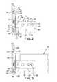
- FIG. 2is a side view of the attachment clip provisionally set on a trim strip
- FIG. 3is a side view of the attachment clip assembled and locked on the trim strip and a grid runner attached to the clip.
- an attachment clip 10has a main body 11 , a backer plate 12 , and a machine screw 13 .
- the main body 11 and backer plate 12are preferably shaped from steel sheet stock, of for example 19 gauge zinc plated material, into their illustrated configurations.
- the main body 11has intersecting legs 16 , 17 which can be supplied in a right angle configuration and which in use typically lie in vertical planes.
- a larger one of the legs 16attaches with a trim strip 18 and a smaller one of the legs 17 attaches with a grid runner 19 .
- a typical suspension gridwill have numerous grid runners intersecting one or more trim strips 18 .
- the leg 16has a generally planar rectangular mid-section 21 reinforced with vertical embossments 22 adjacent its ends. At an upper side, the leg 16 has a forwardly offset upstanding flange 23 joined to the mid-section 21 with a web 24 . On a lower side of the mid-section 21 are a pair of spaced forwardly extending feet 26 and a central coplanar depending tab 27 . A through slot 28 at a middle of the leg mid-section 21 receives the screw 13 with sufficient clearance to allow the screw to move freely vertically along the slot. Two narrow vertical through slots 29 are provided laterally or horizontally outward of the central screw receiving slot 28 .
- the backer plate 12has a generally planar vertical central portion 31 with an internally threaded hole 32 . At a lower edge, the backer plate 12 has a forwardly offset generally vertical flange 33 and an intermediate inclined web 34 . At its vertical edges, the backer plate 12 includes a pair of tabs 36 , 37 bent rearwardly at right angles to the main portion 31 of the backer plate. The tabs 36 , 37 are proportioned to be received and slide in the slots 29 of the leg 16 .
- the tab 36extends through the plane of the leg mid-section 21 and includes a stepped edge 38 . The stepped edge facilitates a person using a thumb or other finger to move the backer plate 12 up or down relative to the leg 16 .
- the leg 17which is unitary with the trim engaging leg 16 , is a generally planar part with a generally rectangular profile.
- a lower section 41 of the leg 17is demarcated from an upper section 42 by a score line 43 stamped into the sheet stock of the clip 10 .
- a notch 46is aligned with the score line 43 .
- a horizontally oriented through slot 47 and a hole 48are stamped in the upper leg section 42 .
- a hole 49is punched in the clip 10 at a line 51 where the legs 16 , 17 merge to weaken the line and assure that any bending between the legs will occur at this line.
- the trim strip 18preferably is an extruded aluminum product such as that marketed by USG Interiors, LLC under the trademark COMPASSO ELITE®. This product line offers trim strips of different heights, straight lengths and curved lengths all with generally constant cross-section.
- the trim strip 18has an integral mounting track 56 formed on its rear face by a pair of opposed channels 57 , 58 . Each channel or groove 57 , 58 is formed by a vertical flange 59 and a horizontal web 60 .
- the backer plate 12is retained in assembled relation to the main body 11 with the screw 13 assembled through the slot 28 and threaded into the backer plate hole 32 .
- the head of the screw 13faces the clip leg 17 .
- the flange 23can be inserted in the upper groove or channel 57 .
- the clip 10can thus be assembled on the trim strip 18 by positioning it in the mounting track 56 at any desired location, there being no need to slide it from one of the trim strip ends.
- the backer plate 12With the clip 10 in a selected position on a trim strip 18 , the backer plate 12 can be lowered so that its flange 33 is received in the lower groove 58 of the mounting track 56 .
- the screw 13can be tightened to draw the flange 33 towards the vertical track flange 59 while the distal ends of the feet 26 bear against the rear face of the trim strip 18 .
- the clip 10is clamped and locked in place on the trim strip 18 .
- the illustrated grid runner 19has a conventional inverted T-shape.
- the clip 10is attached to the grid runner with a self-tapping screw 66 , as shown in FIG. 3 , assembled through the leg slot 47 .
- a suspension wirecan be passed through the hole 48 for supporting the suspension grid and trim strip 18 .
- the location of the clip 10 along the length of the trim strip 18can be readily adjusted from a position at which it is initially locked. Small adjustments are not made difficult since the broad clamping areas of the flange 33 and feet 26 avoid local deformation of the softer aluminum of the trim strip 18 . Consequently, no dimple or other deformation is created in the trim strip proper or in the track flange 59 which would otherwise prevent the clip from smoothly relocating.
- the lower section 41 of the grid runner attachment leg 17can be removed with a tin snips or like tool.
- the blades of the snipscan be located in the notch 46 and the leg 17 can be cut along the score line 43 .
- Removal of the lower section 41permits the clip 10 to be used with a so-called screw slot style grid runner.
- the screw 66is driven into a web of the tee or grid runner 19 that extends between the lower flange and upper reinforcing bulb.
- the leg 17abuts the grid runner web.
- the leg 17can be bent at the bend line 51 so that the legs 16 , 17 conform to the respective orientations of the grid runner and trim strip.
Landscapes
- Engineering & Computer Science (AREA)
- Architecture (AREA)
- Physics & Mathematics (AREA)
- Electromagnetism (AREA)
- Civil Engineering (AREA)
- Structural Engineering (AREA)
- Vehicle Interior And Exterior Ornaments, Soundproofing, And Insulation (AREA)
Abstract
Description
This application claims the benefit of U.S. provisional patent application Ser. No. 61/605,473, filed Mar. 1, 2012.
The invention relates to a clip for attaching perimeter trim to a suspended ceiling grid.
Suspended ceiling systems can include so-called island ceilings and fascias where all or a part of a perimeter of a ceiling is spaced from any wall. Various trim products and related accessories have been developed to provide a finished look for these wall-free ceiling perimeters. One style of trim is an aluminum extrusion formed with integral, mutually facing channels forming an attachment track on a rear face of the extrusion.
Clips have been devised to attach the perimeter trim to suspended ceiling grid runners. U.S. Pat. No. 7,930,864 discloses an example of the prior art. Prior art clips, when being installed, can cause distortion of the trim if overly tightened, and can be expensive to manufacture. Thus, there has been a need for an easy to use clip for reliably attaching a perimeter trim strip to a suspended ceiling grid while avoiding damage from over tightening.
The invention provides an improved attachment clip for suspended ceiling perimeter trim that is quick and easy to position on a trim strip and that avoids the risk of damage to the strip in the event of over tightening.
The disclosed clip has a main body with divergent legs, one for attachment to the trim strip and the other for attachment to a grid runner. A backer plate is slidably mounted on the trim attachment leg between retracted and extended positions. The backer plate retracted position allows the clip to be installed from any point along the length of a trim strip rather than by sliding it from an end of the trim strip. The clip geometry permits the clip to hang, cantilever fashion, on the trim strip during initial assembly without deploying the backer plate into its extended locking position. Once a location of the clip on the trim strip has been selected, the backer plate can be extended to secure the clip on the trim strip.
The clip is locked in position on the trim strip by tightening a screw assembled through the trim attachment leg into the backer plate. Tightening of the screw pinches or clamps a part of a respective track channel on the rear side of the trim in which the backer plate is received. Since the clamping force is not directed against a mid-section of the trim strip, there is no risk of damaging the appearance of the trim strip. The clamping force of the screw is spread across relatively large flat areas of the trim so that permanent local deformation of the trim is avoided. Consequently, fine readjustment of the position of the clip is not obstructed by edges or bumps which could otherwise be created in the clamped trim area. The grid runner attachment leg incorporates a horizontal cut line that allows a technician to easily modify this leg to mate with different grid runner configurations.
Referring now to the figures, anattachment clip 10 has amain body 11, abacker plate 12, and amachine screw 13. Themain body 11 andbacker plate 12 are preferably shaped from steel sheet stock, of for example19 gauge zinc plated material, into their illustrated configurations. Themain body 11 has intersectinglegs legs 16 attaches with atrim strip 18 and a smaller one of thelegs 17 attaches with agrid runner 19. It will be understood by those working in the art that, while only one grid runner is illustrated, a typical suspension grid will have numerous grid runners intersecting one ormore trim strips 18.
Theleg 16 has a generally planarrectangular mid-section 21 reinforced withvertical embossments 22 adjacent its ends. At an upper side, theleg 16 has a forwardly offsetupstanding flange 23 joined to the mid-section21 with aweb 24. On a lower side of the mid-section21 are a pair of spaced forwardly extendingfeet 26 and a centralcoplanar depending tab 27. A throughslot 28 at a middle of theleg mid-section 21 receives thescrew 13 with sufficient clearance to allow the screw to move freely vertically along the slot. Two narrow vertical throughslots 29 are provided laterally or horizontally outward of the centralscrew receiving slot 28.
Thebacker plate 12 has a generally planar verticalcentral portion 31 with an internally threadedhole 32. At a lower edge, thebacker plate 12 has a forwardly offset generallyvertical flange 33 and an intermediateinclined web 34. At its vertical edges, thebacker plate 12 includes a pair oftabs main portion 31 of the backer plate. Thetabs slots 29 of theleg 16. Thetab 36 extends through the plane of the leg mid-section21 and includes astepped edge 38. The stepped edge facilitates a person using a thumb or other finger to move thebacker plate 12 up or down relative to theleg 16.
Theleg 17, which is unitary with the trimengaging leg 16, is a generally planar part with a generally rectangular profile. Alower section 41 of theleg 17 is demarcated from anupper section 42 by ascore line 43 stamped into the sheet stock of theclip 10. At a distalvertical edge 44, anotch 46 is aligned with thescore line 43. A horizontally oriented throughslot 47 and ahole 48 are stamped in theupper leg section 42. Ahole 49 is punched in theclip 10 at aline 51 where thelegs
Thetrim strip 18 preferably is an extruded aluminum product such as that marketed by USG Interiors, LLC under the trademark COMPASSO ELITE®. This product line offers trim strips of different heights, straight lengths and curved lengths all with generally constant cross-section. Thetrim strip 18 has anintegral mounting track 56 formed on its rear face by a pair ofopposed channels groove vertical flange 59 and ahorizontal web 60.
Thebacker plate 12 is retained in assembled relation to themain body 11 with thescrew 13 assembled through theslot 28 and threaded into thebacker plate hole 32. The head of thescrew 13 faces theclip leg 17. With thebacker plate 12 initially in a raised position on theleg 16, theflange 23 can be inserted in the upper groove orchannel 57. Theclip 10 can thus be assembled on thetrim strip 18 by positioning it in themounting track 56 at any desired location, there being no need to slide it from one of the trim strip ends.
With theclip 10 in a selected position on atrim strip 18, thebacker plate 12 can be lowered so that itsflange 33 is received in thelower groove 58 of themounting track 56. Thescrew 13 can be tightened to draw theflange 33 towards thevertical track flange 59 while the distal ends of thefeet 26 bear against the rear face of thetrim strip 18. As a result, theclip 10 is clamped and locked in place on thetrim strip 18.
The illustratedgrid runner 19 has a conventional inverted T-shape. Theclip 10 is attached to the grid runner with a self-tappingscrew 66, as shown inFIG. 3 , assembled through theleg slot 47. A suspension wire, not shown, can be passed through thehole 48 for supporting the suspension grid andtrim strip 18.
The location of theclip 10 along the length of thetrim strip 18 can be readily adjusted from a position at which it is initially locked. Small adjustments are not made difficult since the broad clamping areas of theflange 33 andfeet 26 avoid local deformation of the softer aluminum of thetrim strip 18. Consequently, no dimple or other deformation is created in the trim strip proper or in thetrack flange 59 which would otherwise prevent the clip from smoothly relocating.
Thelower section 41 of the gridrunner attachment leg 17 can be removed with a tin snips or like tool. The blades of the snips can be located in thenotch 46 and theleg 17 can be cut along thescore line 43. Removal of thelower section 41 permits theclip 10 to be used with a so-called screw slot style grid runner. Thescrew 66 is driven into a web of the tee orgrid runner 19 that extends between the lower flange and upper reinforcing bulb. Theleg 17 abuts the grid runner web.
Where thegrid runner 19 intersects thetrim strip 18 at an obtuse or acute angle, theleg 17 can be bent at thebend line 51 so that thelegs
It should be evident that this disclosure is by way of example and that various changes may be made by adding, modifying or eliminating details without departing from the fair scope of the teaching contained in this disclosure. The invention is therefore not limited to particular details of this disclosure except to the extent that the following claims are necessarily so limited.
Claims (6)
1. A stamped sheet metal clip for attaching an elongated trim strip to a grid runner in an angular relationship, the clip having a first leg for attachment to the trim strip and a second leg for attachment to the grid runner, the first leg having a backer plate attached with a screw, the screw extending through a slot in the first leg, a head of the screw being disposed on a side of the first leg facing the second leg, the backer plate being disposed on a side of the first leg opposing the side facing the second leg, an upper edge of the first leg being adapted to fit in an upper downwardly facing groove formed by a depending upper free edge of the trim strip on a back side of the trim strip, the backer plate being adapted to pass between the depending free edge of the upper groove and an upstanding lower free edge of the trim strip on the back side of the trim strip forming a lower upwardly facing groove when the screw attaching the backer plate is in an upper part of the slot, and being adapted to be received in the lower groove when the screw is in a lower part of the slot and to clamp against the lower foot free edge as a lower part of the first leg bears against the rear face of the trim strip at a location above the lower free edge and a depending tab of the first leg rests on a lower part of the trim strip; wherein the first leg has a midsection, the depending tab projecting in a direction parallel to the midsection and the lower foot part projecting in a direction substantially perpendicular to the midsection, the depending tab and the lower foot part being downwardly spaced from the upper edge.
2. An attachment clip as set forth inclaim 1 , wherein the backer plate has a tab extending through a narrow slot in the first leg, the tab having a length greater than the thickness of the first leg such that it is engageable by a finger of a technician installing the clip to manipulate the backer plate in or out of engagement with the lower groove.
3. An attachment clip as set forth inclaim 1 , wherein the backer plate has a second tab extending into a second narrow slot in the first leg parallel to said first narrow slot.
4. An attachment clip as set forth inclaim 1 , wherein said second leg is formed with an aperture.
5. An attachment clip as set forth inclaim 4 , wherein said aperture is an elongated slot.
6. A attachment clip as set forth inclaim 5 , wherein said second leg is horizontally scored to facilitate cutting a lower portion of the second leg from the clip to accommodate a grid runner with a lower flange having a box-like configuration.
Priority Applications (2)
| Application Number | Priority Date | Filing Date | Title |
|---|---|---|---|
| US13/776,974US8763336B2 (en) | 2012-03-01 | 2013-02-26 | Attachment clip for ceiling grid systems |
| PCT/US2013/027864WO2013130494A1 (en) | 2012-03-01 | 2013-02-27 | Attachment clip for ceiling grid systems |
Applications Claiming Priority (2)
| Application Number | Priority Date | Filing Date | Title |
|---|---|---|---|
| US201261605473P | 2012-03-01 | 2012-03-01 | |
| US13/776,974US8763336B2 (en) | 2012-03-01 | 2013-02-26 | Attachment clip for ceiling grid systems |
Publications (2)
| Publication Number | Publication Date |
|---|---|
| US20130227908A1 US20130227908A1 (en) | 2013-09-05 |
| US8763336B2true US8763336B2 (en) | 2014-07-01 |
Family
ID=49042029
Family Applications (1)
| Application Number | Title | Priority Date | Filing Date |
|---|---|---|---|
| US13/776,974ActiveUS8763336B2 (en) | 2012-03-01 | 2013-02-26 | Attachment clip for ceiling grid systems |
Country Status (2)
| Country | Link |
|---|---|
| US (1) | US8763336B2 (en) |
| WO (1) | WO2013130494A1 (en) |
Cited By (13)
| Publication number | Priority date | Publication date | Assignee | Title |
|---|---|---|---|---|
| US9255403B1 (en)* | 2014-08-19 | 2016-02-09 | Usg Interiors, Llc | Free span ceiling grid system |
| US20180202628A1 (en)* | 2015-10-09 | 2018-07-19 | Worthington Armstrong Venture | Indirect light cove |
| US20180266101A1 (en)* | 2018-03-16 | 2018-09-20 | Telling Industries, LLC | Adjustable clip |
| USD839078S1 (en) | 2018-01-04 | 2019-01-29 | Clarkwestern Dietrich Building Systems Llc | Slide clip |
| USD959250S1 (en) | 2020-07-22 | 2022-08-02 | Clarkwestern Dietrich Building Systems Llc | Slide clip |
| USD959251S1 (en) | 2020-07-22 | 2022-08-02 | Clarkwestern Dietrich Building Systems Llc | Slide clip |
| USD962048S1 (en) | 2019-04-30 | 2022-08-30 | Hunter Douglas Inc. | Coupling device for mounting tiles to a building |
| US11692340B2 (en) | 2020-07-22 | 2023-07-04 | Clarkwestern Dietrich Building Systems Llc | Slide clip |
| US20230407633A1 (en)* | 2018-05-24 | 2023-12-21 | Armstrong World Industries, Inc. | Ceiling system |
| US11905713B2 (en) | 2019-04-30 | 2024-02-20 | Hunter Douglas Inc. | Coupling system for mounting tiles to a building |
| US12011088B2 (en) | 2021-10-22 | 2024-06-18 | Silicate Studio Home LLC | Floating shelf bracket with welded rods |
| US12137805B2 (en) | 2021-10-22 | 2024-11-12 | Silicate Studio Home, LLC | Floating shelf bracket with threaded rods |
| US12144424B2 (en)* | 2021-10-22 | 2024-11-19 | Silicate Studio Home, LLC | Floating shelf bracket |
Families Citing this family (36)
| Publication number | Priority date | Publication date | Assignee | Title |
|---|---|---|---|---|
| US8820026B2 (en)* | 2013-02-01 | 2014-09-02 | Usg Interiors, Llc | Clip for perimeter trim |
| US10551044B2 (en) | 2015-11-16 | 2020-02-04 | DMF, Inc. | Recessed lighting assembly |
| US11255497B2 (en) | 2013-07-05 | 2022-02-22 | DMF, Inc. | Adjustable electrical apparatus with hangar bars for installation in a building |
| US11060705B1 (en) | 2013-07-05 | 2021-07-13 | DMF, Inc. | Compact lighting apparatus with AC to DC converter and integrated electrical connector |
| US10753558B2 (en) | 2013-07-05 | 2020-08-25 | DMF, Inc. | Lighting apparatus and methods |
| US11435064B1 (en) | 2013-07-05 | 2022-09-06 | DMF, Inc. | Integrated lighting module |
| US10591120B2 (en) | 2015-05-29 | 2020-03-17 | DMF, Inc. | Lighting module for recessed lighting systems |
| US10139059B2 (en) | 2014-02-18 | 2018-11-27 | DMF, Inc. | Adjustable compact recessed lighting assembly with hangar bars |
| US10563850B2 (en) | 2015-04-22 | 2020-02-18 | DMF, Inc. | Outer casing for a recessed lighting fixture |
| US9964266B2 (en) | 2013-07-05 | 2018-05-08 | DMF, Inc. | Unified driver and light source assembly for recessed lighting |
| AU2014289969B2 (en)* | 2013-07-09 | 2018-05-17 | Studform Pty Ltd | Seismic ceiling system |
| PL3097240T3 (en)* | 2014-01-16 | 2018-08-31 | Rockwool International A/S | Suspended ceiling grid clip for securing an unopposed cross tee to a main runner |
| USD851046S1 (en) | 2015-10-05 | 2019-06-11 | DMF, Inc. | Electrical Junction Box |
| US9920524B2 (en)* | 2016-01-19 | 2018-03-20 | Usg Interiors, Llc | Trim strip system for use with underhung ceiling panels |
| US10100519B2 (en)* | 2016-08-30 | 2018-10-16 | Awi Licensing Llc | Ceiling system and mounting bracket for use with the same |
| US10488000B2 (en) | 2017-06-22 | 2019-11-26 | DMF, Inc. | Thin profile surface mount lighting apparatus |
| WO2018237294A2 (en) | 2017-06-22 | 2018-12-27 | DMF, Inc. | THIN-PROFILE SURFACE MOUNTING LIGHTING DEVICE |
| USD905327S1 (en) | 2018-05-17 | 2020-12-15 | DMF, Inc. | Light fixture |
| US11067231B2 (en) | 2017-08-28 | 2021-07-20 | DMF, Inc. | Alternate junction box and arrangement for lighting apparatus |
| CA3083359A1 (en) | 2017-11-28 | 2019-06-06 | DMF, Inc. | Adjustable hanger bar assembly |
| WO2019211751A1 (en)* | 2018-05-01 | 2019-11-07 | Rockwool International A/S | Bridging connectors for suspended ceiling systems |
| USD877957S1 (en) | 2018-05-24 | 2020-03-10 | DMF Inc. | Light fixture |
| WO2019241198A1 (en) | 2018-06-11 | 2019-12-19 | DMF, Inc. | A polymer housing for a recessed lighting system and methods for using same |
| USD903605S1 (en) | 2018-06-12 | 2020-12-01 | DMF, Inc. | Plastic deep electrical junction box |
| WO2020072592A1 (en)* | 2018-10-02 | 2020-04-09 | Ver Lighting Llc | A bar hanger assembly with mating telescoping bars |
| USD1012864S1 (en) | 2019-01-29 | 2024-01-30 | DMF, Inc. | Portion of a plastic deep electrical junction box |
| USD901398S1 (en) | 2019-01-29 | 2020-11-10 | DMF, Inc. | Plastic deep electrical junction box |
| USD966877S1 (en) | 2019-03-14 | 2022-10-18 | Ver Lighting Llc | Hanger bar for a hanger bar assembly |
| WO2021051101A1 (en) | 2019-09-12 | 2021-03-18 | DMF, Inc. | Miniature lighting module and lighting fixtures using same |
| USD1009309S1 (en)* | 2020-04-21 | 2023-12-26 | Rockwool A/S | Grid tee for suspended ceiling |
| CA3124969A1 (en) | 2020-07-16 | 2022-01-16 | DMF, Inc. | Round metal housing for a lighting system |
| CA3124976A1 (en) | 2020-07-17 | 2022-01-17 | DMF, Inc. | Polymer housing for a lighting system and methods for using same |
| USD990030S1 (en) | 2020-07-17 | 2023-06-20 | DMF, Inc. | Housing for a lighting system |
| CA3124987A1 (en) | 2020-07-17 | 2022-01-17 | DMF, Inc. | Bar hanger assembly with crossmembers and housing assemblies using same |
| US11585517B2 (en) | 2020-07-23 | 2023-02-21 | DMF, Inc. | Lighting module having field-replaceable optics, improved cooling, and tool-less mounting features |
| CN117266436B (en)* | 2023-09-18 | 2025-03-14 | 上海市建筑装饰工程集团有限公司 | Assembled level that falls conversion layer and assembly |
Citations (42)
| Publication number | Priority date | Publication date | Assignee | Title |
|---|---|---|---|---|
| US2217574A (en)* | 1939-04-15 | 1940-10-08 | Tinnerman Products Inc | Molding construction |
| US3294428A (en)* | 1963-08-07 | 1966-12-27 | Lickliter | Expansion joint and locking connection for supporting grid systems |
| US3742668A (en)* | 1971-05-19 | 1973-07-03 | Bendix Corp | Corner closure assembly |
| US3798865A (en)* | 1972-03-17 | 1974-03-26 | Integrated Ceilings Inc | Grid support structure and clip means therefor |
| US3823251A (en)* | 1972-06-12 | 1974-07-09 | Mesco Metal Buildings Corp | Electrical connector for interior wall panels |
| US3898782A (en)* | 1974-01-04 | 1975-08-12 | Lightolier Inc | Integrated ceiling system |
| US4580386A (en)* | 1981-12-14 | 1986-04-08 | Armstrong World Industries, Inc. | Expansion clip on a ceiling runner |
| US4642957A (en)* | 1984-12-11 | 1987-02-17 | Edwards Troy C | Interior wall trim system |
| US4663911A (en)* | 1984-05-24 | 1987-05-12 | Andia Louvers, S.A. | Device for securing profiles for concealed suspension lattice work ceilings |
| US4725083A (en)* | 1985-04-06 | 1988-02-16 | Michael Komotzki | Flanged joint for two sheet material air channel sections of rectangular cross section |
| US4850172A (en)* | 1986-04-25 | 1989-07-25 | Alcan Aluminum Corporation | Ceiling or like structural system and splice member therefor |
| US5154031A (en)* | 1991-03-26 | 1992-10-13 | Schilling Components, Incorporated | Suspended ceiling system and connector clip therefor |
| US5195289A (en)* | 1991-05-31 | 1993-03-23 | Usg Interiors, Inc. | Trim system for suspension ceilings |
| US5309686A (en)* | 1992-02-19 | 1994-05-10 | Kimball International, Inc. | Work space partition system |
| US5313759A (en)* | 1991-12-18 | 1994-05-24 | Chase Iii Francis H | Cleanroom ceiling system |
| US5350227A (en)* | 1992-09-16 | 1994-09-27 | Robern, Inc. | Spacer for filling a space between two adjacent modular cabinets |
| US5359817A (en)* | 1991-02-19 | 1994-11-01 | Transfer Flow International, Inc. | Architectural moldings of rigid thermoset polymer based material |
| US5426901A (en)* | 1993-08-27 | 1995-06-27 | Indracek; Jaroslav | Molding assembly |
| US5572844A (en)* | 1995-04-24 | 1996-11-12 | Armstrong World Industries, Inc. | Runner-trim connector |
| US5678379A (en)* | 1995-03-15 | 1997-10-21 | Quattrociocchi; Luciano | Bottom plate anchor for building frames |
| US5732747A (en)* | 1997-01-21 | 1998-03-31 | Icm Corporation | Cove molding cover for electrical cables |
| US5937605A (en)* | 1998-02-18 | 1999-08-17 | Usg Interiors, Inc. | Adjustable face trim clip for drywall suspension grid |
| US6018923A (en)* | 1997-12-16 | 2000-02-01 | Usg Interiors, Inc. | Transition clip for drywall suspension grid |
| US6138425A (en)* | 1997-12-16 | 2000-10-31 | Usg Interiors, Inc. | Splice clip for drywall suspension grid |
| US6141926A (en)* | 1995-10-26 | 2000-11-07 | Tetrad Marketing/Sales Ltd. | Panel construction and connection system |
| US20020152704A1 (en)* | 2001-02-15 | 2002-10-24 | Thompson Eugene W. | Ceiling panel and support system |
| US20030177735A1 (en)* | 2002-02-06 | 2003-09-25 | Gary Seeba | Built-up beam assembly for building structures |
| US20030230043A1 (en)* | 2002-06-14 | 2003-12-18 | Likozar Martin E. | Scalable suspension system for dome shaped ceilings |
| US6763641B1 (en)* | 2002-07-02 | 2004-07-20 | Usg Interiors, Inc. | Gridless free form plank ceiling |
| US20050034410A1 (en)* | 2003-07-30 | 2005-02-17 | Stackenwalt Richard D. | Trim of a ceiling system and method of assembling the same |
| US6880302B1 (en)* | 2000-03-20 | 2005-04-19 | Newmat, Sa | Elements of stretched false ceiling, use of same for producing false walls and false ceilings |
| US20060102883A1 (en)* | 2004-09-29 | 2006-05-18 | Creative Pultrusions, Inc. | Pultruded composite guardrail |
| US20070130869A1 (en)* | 2005-12-02 | 2007-06-14 | Worthington Armstrong Venture | Suspended ceiling segment |
| US7461484B2 (en)* | 2002-02-15 | 2008-12-09 | Steelcase Inc. | Customizable partition system |
| US7788872B2 (en)* | 2008-03-06 | 2010-09-07 | Worthington Armstrong Venture | Seismic main beam connection |
| US7930864B2 (en) | 2009-02-11 | 2011-04-26 | Usg Interiors, Inc. | Mounting clip |
| USD638287S1 (en)* | 2010-12-01 | 2011-05-24 | Usg Interiors, Inc. | Seismic attachment clip for suspended ceilings |
| US8006454B2 (en)* | 2004-10-27 | 2011-08-30 | Chicago Metallic Corporation | Suspended ceiling system |
| US20110226919A1 (en)* | 2010-03-18 | 2011-09-22 | Juno Manufacturing, LLC | Telescoping mounting system for a recessed luminaire |
| US20130180202A1 (en)* | 2012-01-18 | 2013-07-18 | Kimball International, Inc. | Wall rail system |
| US8522498B2 (en)* | 2008-10-04 | 2013-09-03 | Heath D. Picken | System and method for removably connecting trim to a wall or ceiling or both |
| US8534016B2 (en)* | 2009-03-30 | 2013-09-17 | Robert Depaul | Corner wall conduit |
- 2013
- 2013-02-26USUS13/776,974patent/US8763336B2/enactiveActive
- 2013-02-27WOPCT/US2013/027864patent/WO2013130494A1/enactiveApplication Filing
Patent Citations (42)
| Publication number | Priority date | Publication date | Assignee | Title |
|---|---|---|---|---|
| US2217574A (en)* | 1939-04-15 | 1940-10-08 | Tinnerman Products Inc | Molding construction |
| US3294428A (en)* | 1963-08-07 | 1966-12-27 | Lickliter | Expansion joint and locking connection for supporting grid systems |
| US3742668A (en)* | 1971-05-19 | 1973-07-03 | Bendix Corp | Corner closure assembly |
| US3798865A (en)* | 1972-03-17 | 1974-03-26 | Integrated Ceilings Inc | Grid support structure and clip means therefor |
| US3823251A (en)* | 1972-06-12 | 1974-07-09 | Mesco Metal Buildings Corp | Electrical connector for interior wall panels |
| US3898782A (en)* | 1974-01-04 | 1975-08-12 | Lightolier Inc | Integrated ceiling system |
| US4580386A (en)* | 1981-12-14 | 1986-04-08 | Armstrong World Industries, Inc. | Expansion clip on a ceiling runner |
| US4663911A (en)* | 1984-05-24 | 1987-05-12 | Andia Louvers, S.A. | Device for securing profiles for concealed suspension lattice work ceilings |
| US4642957A (en)* | 1984-12-11 | 1987-02-17 | Edwards Troy C | Interior wall trim system |
| US4725083A (en)* | 1985-04-06 | 1988-02-16 | Michael Komotzki | Flanged joint for two sheet material air channel sections of rectangular cross section |
| US4850172A (en)* | 1986-04-25 | 1989-07-25 | Alcan Aluminum Corporation | Ceiling or like structural system and splice member therefor |
| US5359817A (en)* | 1991-02-19 | 1994-11-01 | Transfer Flow International, Inc. | Architectural moldings of rigid thermoset polymer based material |
| US5154031A (en)* | 1991-03-26 | 1992-10-13 | Schilling Components, Incorporated | Suspended ceiling system and connector clip therefor |
| US5195289A (en)* | 1991-05-31 | 1993-03-23 | Usg Interiors, Inc. | Trim system for suspension ceilings |
| US5313759A (en)* | 1991-12-18 | 1994-05-24 | Chase Iii Francis H | Cleanroom ceiling system |
| US5309686A (en)* | 1992-02-19 | 1994-05-10 | Kimball International, Inc. | Work space partition system |
| US5350227A (en)* | 1992-09-16 | 1994-09-27 | Robern, Inc. | Spacer for filling a space between two adjacent modular cabinets |
| US5426901A (en)* | 1993-08-27 | 1995-06-27 | Indracek; Jaroslav | Molding assembly |
| US5678379A (en)* | 1995-03-15 | 1997-10-21 | Quattrociocchi; Luciano | Bottom plate anchor for building frames |
| US5572844A (en)* | 1995-04-24 | 1996-11-12 | Armstrong World Industries, Inc. | Runner-trim connector |
| US6141926A (en)* | 1995-10-26 | 2000-11-07 | Tetrad Marketing/Sales Ltd. | Panel construction and connection system |
| US5732747A (en)* | 1997-01-21 | 1998-03-31 | Icm Corporation | Cove molding cover for electrical cables |
| US6138425A (en)* | 1997-12-16 | 2000-10-31 | Usg Interiors, Inc. | Splice clip for drywall suspension grid |
| US6018923A (en)* | 1997-12-16 | 2000-02-01 | Usg Interiors, Inc. | Transition clip for drywall suspension grid |
| US5937605A (en)* | 1998-02-18 | 1999-08-17 | Usg Interiors, Inc. | Adjustable face trim clip for drywall suspension grid |
| US6880302B1 (en)* | 2000-03-20 | 2005-04-19 | Newmat, Sa | Elements of stretched false ceiling, use of same for producing false walls and false ceilings |
| US20020152704A1 (en)* | 2001-02-15 | 2002-10-24 | Thompson Eugene W. | Ceiling panel and support system |
| US20030177735A1 (en)* | 2002-02-06 | 2003-09-25 | Gary Seeba | Built-up beam assembly for building structures |
| US7461484B2 (en)* | 2002-02-15 | 2008-12-09 | Steelcase Inc. | Customizable partition system |
| US20030230043A1 (en)* | 2002-06-14 | 2003-12-18 | Likozar Martin E. | Scalable suspension system for dome shaped ceilings |
| US6763641B1 (en)* | 2002-07-02 | 2004-07-20 | Usg Interiors, Inc. | Gridless free form plank ceiling |
| US20050034410A1 (en)* | 2003-07-30 | 2005-02-17 | Stackenwalt Richard D. | Trim of a ceiling system and method of assembling the same |
| US20060102883A1 (en)* | 2004-09-29 | 2006-05-18 | Creative Pultrusions, Inc. | Pultruded composite guardrail |
| US8006454B2 (en)* | 2004-10-27 | 2011-08-30 | Chicago Metallic Corporation | Suspended ceiling system |
| US20070130869A1 (en)* | 2005-12-02 | 2007-06-14 | Worthington Armstrong Venture | Suspended ceiling segment |
| US7788872B2 (en)* | 2008-03-06 | 2010-09-07 | Worthington Armstrong Venture | Seismic main beam connection |
| US8522498B2 (en)* | 2008-10-04 | 2013-09-03 | Heath D. Picken | System and method for removably connecting trim to a wall or ceiling or both |
| US7930864B2 (en) | 2009-02-11 | 2011-04-26 | Usg Interiors, Inc. | Mounting clip |
| US8534016B2 (en)* | 2009-03-30 | 2013-09-17 | Robert Depaul | Corner wall conduit |
| US20110226919A1 (en)* | 2010-03-18 | 2011-09-22 | Juno Manufacturing, LLC | Telescoping mounting system for a recessed luminaire |
| USD638287S1 (en)* | 2010-12-01 | 2011-05-24 | Usg Interiors, Inc. | Seismic attachment clip for suspended ceilings |
| US20130180202A1 (en)* | 2012-01-18 | 2013-07-18 | Kimball International, Inc. | Wall rail system |
Non-Patent Citations (1)
| Title |
|---|
| International Search Report and Written Opinion of the International Searching Authority dated Jun. 21, 2013 for corresponding International Application No. PCT/US20131027864, filed Feb. 27, 2013. |
Cited By (22)
| Publication number | Priority date | Publication date | Assignee | Title |
|---|---|---|---|---|
| US9255403B1 (en)* | 2014-08-19 | 2016-02-09 | Usg Interiors, Llc | Free span ceiling grid system |
| US9663948B2 (en) | 2014-08-19 | 2017-05-30 | Usg Interiors, Llc | Free span ceiling grid system |
| US9909312B2 (en) | 2014-08-19 | 2018-03-06 | Usg Interiors, Llc | Free span ceiling grid system |
| US10928031B2 (en)* | 2015-10-09 | 2021-02-23 | Worthington Armstrong Venture | Indirect light cove |
| US20180202628A1 (en)* | 2015-10-09 | 2018-07-19 | Worthington Armstrong Venture | Indirect light cove |
| USD839078S1 (en) | 2018-01-04 | 2019-01-29 | Clarkwestern Dietrich Building Systems Llc | Slide clip |
| US20180266101A1 (en)* | 2018-03-16 | 2018-09-20 | Telling Industries, LLC | Adjustable clip |
| US10323414B2 (en)* | 2018-03-16 | 2019-06-18 | Telling Industries, LLC | Adjustable clip |
| US20190292784A1 (en)* | 2018-03-16 | 2019-09-26 | Telling Industries, LLC | Adjustable clip |
| US10597872B2 (en)* | 2018-03-16 | 2020-03-24 | Telling Industries, LLC | Adjustable clip |
| US12320116B2 (en)* | 2018-05-24 | 2025-06-03 | Awi Licensing Llc | Ceiling system |
| US20230407633A1 (en)* | 2018-05-24 | 2023-12-21 | Armstrong World Industries, Inc. | Ceiling system |
| US11905713B2 (en) | 2019-04-30 | 2024-02-20 | Hunter Douglas Inc. | Coupling system for mounting tiles to a building |
| US12320129B2 (en) | 2019-04-30 | 2025-06-03 | Hunter Douglas Inc. | Coupling system for mounting tiles to a building |
| USD962048S1 (en) | 2019-04-30 | 2022-08-30 | Hunter Douglas Inc. | Coupling device for mounting tiles to a building |
| USD959250S1 (en) | 2020-07-22 | 2022-08-02 | Clarkwestern Dietrich Building Systems Llc | Slide clip |
| US11905700B2 (en) | 2020-07-22 | 2024-02-20 | Clarkwestern Dietrich Building Systems Llc | Slide clip |
| US11692340B2 (en) | 2020-07-22 | 2023-07-04 | Clarkwestern Dietrich Building Systems Llc | Slide clip |
| USD959251S1 (en) | 2020-07-22 | 2022-08-02 | Clarkwestern Dietrich Building Systems Llc | Slide clip |
| US12011088B2 (en) | 2021-10-22 | 2024-06-18 | Silicate Studio Home LLC | Floating shelf bracket with welded rods |
| US12137805B2 (en) | 2021-10-22 | 2024-11-12 | Silicate Studio Home, LLC | Floating shelf bracket with threaded rods |
| US12144424B2 (en)* | 2021-10-22 | 2024-11-19 | Silicate Studio Home, LLC | Floating shelf bracket |
Also Published As
| Publication number | Publication date |
|---|---|
| US20130227908A1 (en) | 2013-09-05 |
| WO2013130494A1 (en) | 2013-09-06 |
Similar Documents
| Publication | Publication Date | Title |
|---|---|---|
| US8763336B2 (en) | Attachment clip for ceiling grid systems | |
| CN104350219B (en) | Peripheral decorative clips for grill joists | |
| US10006613B2 (en) | Bar hanger with substantially identical members for recessed luminaires | |
| US8702047B2 (en) | Electrical box mounting bracket | |
| US8746633B1 (en) | Cable positioning bracket | |
| US20120110944A1 (en) | Fastener for building materials | |
| US20020152704A1 (en) | Ceiling panel and support system | |
| KR102026241B1 (en) | Clip for perimeter trim | |
| US8782985B2 (en) | Splice clip for ceiling grid systems | |
| US8387927B1 (en) | Cable positioning bracket | |
| CN105178497A (en) | Clip-on extruded moldings for ceiling grid | |
| US20240374066A1 (en) | Mounting Bracket | |
| US9464433B1 (en) | Self-tightening splice | |
| RU175224U1 (en) | The fastening device for the cladding element at the junction of two surfaces | |
| RU184567U1 (en) | DEVICE FOR FASTENING THE FACING ELEMENT IN THE PLACE OF PAIRING TWO SURFACES | |
| JP7068786B2 (en) | Panel fixture | |
| US7017947B1 (en) | Pipe holder | |
| AU2018201395A1 (en) | Support Bracket |
Legal Events
| Date | Code | Title | Description |
|---|---|---|---|
| AS | Assignment | Owner name:USG INTERIORS, LLC, ILLINOIS Free format text:ASSIGNMENT OF ASSIGNORS INTEREST;ASSIGNORS:GULBRANDSEN, PEDER;MIKLOSZ, MARK;JACKSON, NICHOLAS;AND OTHERS;SIGNING DATES FROM 20130206 TO 20130222;REEL/FRAME:029875/0384 | |
| FEPP | Fee payment procedure | Free format text:PAYOR NUMBER ASSIGNED (ORIGINAL EVENT CODE: ASPN); ENTITY STATUS OF PATENT OWNER: LARGE ENTITY | |
| STCF | Information on status: patent grant | Free format text:PATENTED CASE | |
| MAFP | Maintenance fee payment | Free format text:PAYMENT OF MAINTENANCE FEE, 4TH YEAR, LARGE ENTITY (ORIGINAL EVENT CODE: M1551) Year of fee payment:4 | |
| MAFP | Maintenance fee payment | Free format text:PAYMENT OF MAINTENANCE FEE, 8TH YEAR, LARGE ENTITY (ORIGINAL EVENT CODE: M1552); ENTITY STATUS OF PATENT OWNER: LARGE ENTITY Year of fee payment:8 |