US8761991B1 - Use of uncertainty regarding observations of traffic intersections to modify behavior of a vehicle - Google Patents
Use of uncertainty regarding observations of traffic intersections to modify behavior of a vehicleDownload PDFInfo
- Publication number
- US8761991B1 US8761991B1US13/441,996US201213441996AUS8761991B1US 8761991 B1US8761991 B1US 8761991B1US 201213441996 AUS201213441996 AUS 201213441996AUS 8761991 B1US8761991 B1US 8761991B1
- Authority
- US
- United States
- Prior art keywords
- state
- vehicle
- traffic
- traffic intersection
- determined
- Prior art date
- Legal status (The legal status is an assumption and is not a legal conclusion. Google has not performed a legal analysis and makes no representation as to the accuracy of the status listed.)
- Active, expires
Links
- 238000000034methodMethods0.000claimsabstractdescription46
- 230000006870functionEffects0.000claimsdescription12
- 238000004891communicationMethods0.000description30
- 230000001276controlling effectEffects0.000description9
- 230000002093peripheral effectEffects0.000description9
- 230000006399behaviorEffects0.000description8
- 238000013500data storageMethods0.000description8
- 230000008569processEffects0.000description8
- 238000004590computer programMethods0.000description7
- 238000003384imaging methodMethods0.000description7
- 230000005540biological transmissionEffects0.000description6
- 230000004927fusionEffects0.000description6
- 238000012545processingMethods0.000description6
- 238000010586diagramMethods0.000description5
- 230000008859changeEffects0.000description4
- 238000001514detection methodMethods0.000description4
- 230000007246mechanismEffects0.000description4
- 238000013179statistical modelMethods0.000description4
- 238000011156evaluationMethods0.000description3
- 239000000446fuelSubstances0.000description3
- 230000033001locomotionEffects0.000description3
- LFQSCWFLJHTTHZ-UHFFFAOYSA-NEthanolChemical compoundCCOLFQSCWFLJHTTHZ-UHFFFAOYSA-N0.000description2
- ATUOYWHBWRKTHZ-UHFFFAOYSA-NPropaneChemical compoundCCCATUOYWHBWRKTHZ-UHFFFAOYSA-N0.000description2
- 230000001133accelerationEffects0.000description2
- 238000013459approachMethods0.000description2
- 230000001413cellular effectEffects0.000description2
- 238000010276constructionMethods0.000description2
- -1dieselSubstances0.000description2
- 238000005516engineering processMethods0.000description2
- 239000003502gasolineSubstances0.000description2
- 238000004519manufacturing processMethods0.000description2
- 239000000463materialSubstances0.000description2
- 238000005259measurementMethods0.000description2
- 230000003287optical effectEffects0.000description2
- HBBGRARXTFLTSG-UHFFFAOYSA-NLithium ionChemical compound[Li+]HBBGRARXTFLTSG-UHFFFAOYSA-N0.000description1
- 239000002253acidSubstances0.000description1
- 239000003990capacitorSubstances0.000description1
- 230000001427coherent effectEffects0.000description1
- 238000002485combustion reactionMethods0.000description1
- 239000000835fiberSubstances0.000description1
- 230000005057finger movementEffects0.000description1
- 239000002828fuel tankSubstances0.000description1
- 230000003116impacting effectEffects0.000description1
- 238000005305interferometryMethods0.000description1
- 229910001416lithium ionInorganic materials0.000description1
- 230000007774longtermEffects0.000description1
- 239000002184metalSubstances0.000description1
- 238000012986modificationMethods0.000description1
- 230000004048modificationEffects0.000description1
- 239000010705motor oilSubstances0.000description1
- 230000002085persistent effectEffects0.000description1
- 238000003672processing methodMethods0.000description1
- 239000001294propaneSubstances0.000description1
- 230000001105regulatory effectEffects0.000description1
- 230000004044responseEffects0.000description1
- 238000001228spectrumMethods0.000description1
- 238000010897surface acoustic wave methodMethods0.000description1
- 238000002366time-of-flight methodMethods0.000description1
Images


Classifications
- G—PHYSICS
- G05—CONTROLLING; REGULATING
- G05D—SYSTEMS FOR CONTROLLING OR REGULATING NON-ELECTRIC VARIABLES
- G05D1/00—Control of position, course, altitude or attitude of land, water, air or space vehicles, e.g. using automatic pilots
- G05D1/0088—Control of position, course, altitude or attitude of land, water, air or space vehicles, e.g. using automatic pilots characterized by the autonomous decision making process, e.g. artificial intelligence, predefined behaviours
- B—PERFORMING OPERATIONS; TRANSPORTING
- B60—VEHICLES IN GENERAL
- B60W—CONJOINT CONTROL OF VEHICLE SUB-UNITS OF DIFFERENT TYPE OR DIFFERENT FUNCTION; CONTROL SYSTEMS SPECIALLY ADAPTED FOR HYBRID VEHICLES; ROAD VEHICLE DRIVE CONTROL SYSTEMS FOR PURPOSES NOT RELATED TO THE CONTROL OF A PARTICULAR SUB-UNIT
- B60W30/00—Purposes of road vehicle drive control systems not related to the control of a particular sub-unit, e.g. of systems using conjoint control of vehicle sub-units
- B60W30/18—Propelling the vehicle
- B60W30/18009—Propelling the vehicle related to particular drive situations
- B60W30/18154—Approaching an intersection
- G—PHYSICS
- G08—SIGNALLING
- G08G—TRAFFIC CONTROL SYSTEMS
- G08G1/00—Traffic control systems for road vehicles
- G08G1/09—Arrangements for giving variable traffic instructions
- G08G1/0962—Arrangements for giving variable traffic instructions having an indicator mounted inside the vehicle, e.g. giving voice messages
- G08G1/09623—Systems involving the acquisition of information from passive traffic signs by means mounted on the vehicle
- G—PHYSICS
- G08—SIGNALLING
- G08G—TRAFFIC CONTROL SYSTEMS
- G08G1/00—Traffic control systems for road vehicles
- G08G1/09—Arrangements for giving variable traffic instructions
- G08G1/0962—Arrangements for giving variable traffic instructions having an indicator mounted inside the vehicle, e.g. giving voice messages
- G08G1/0967—Systems involving transmission of highway information, e.g. weather, speed limits
- G08G1/096708—Systems involving transmission of highway information, e.g. weather, speed limits where the received information might be used to generate an automatic action on the vehicle control
- G08G1/096725—Systems involving transmission of highway information, e.g. weather, speed limits where the received information might be used to generate an automatic action on the vehicle control where the received information generates an automatic action on the vehicle control
- G—PHYSICS
- G08—SIGNALLING
- G08G—TRAFFIC CONTROL SYSTEMS
- G08G1/00—Traffic control systems for road vehicles
- G08G1/09—Arrangements for giving variable traffic instructions
- G08G1/0962—Arrangements for giving variable traffic instructions having an indicator mounted inside the vehicle, e.g. giving voice messages
- G08G1/0967—Systems involving transmission of highway information, e.g. weather, speed limits
- G08G1/096733—Systems involving transmission of highway information, e.g. weather, speed limits where a selection of the information might take place
- G08G1/096758—Systems involving transmission of highway information, e.g. weather, speed limits where a selection of the information might take place where no selection takes place on the transmitted or the received information
- G—PHYSICS
- G08—SIGNALLING
- G08G—TRAFFIC CONTROL SYSTEMS
- G08G1/00—Traffic control systems for road vehicles
- G08G1/09—Arrangements for giving variable traffic instructions
- G08G1/0962—Arrangements for giving variable traffic instructions having an indicator mounted inside the vehicle, e.g. giving voice messages
- G08G1/0967—Systems involving transmission of highway information, e.g. weather, speed limits
- G08G1/096766—Systems involving transmission of highway information, e.g. weather, speed limits where the system is characterised by the origin of the information transmission
- G08G1/096783—Systems involving transmission of highway information, e.g. weather, speed limits where the system is characterised by the origin of the information transmission where the origin of the information is a roadside individual element
- B—PERFORMING OPERATIONS; TRANSPORTING
- B60—VEHICLES IN GENERAL
- B60W—CONJOINT CONTROL OF VEHICLE SUB-UNITS OF DIFFERENT TYPE OR DIFFERENT FUNCTION; CONTROL SYSTEMS SPECIALLY ADAPTED FOR HYBRID VEHICLES; ROAD VEHICLE DRIVE CONTROL SYSTEMS FOR PURPOSES NOT RELATED TO THE CONTROL OF A PARTICULAR SUB-UNIT
- B60W2555/00—Input parameters relating to exterior conditions, not covered by groups B60W2552/00, B60W2554/00
- B60W2555/60—Traffic rules, e.g. speed limits or right of way
Definitions
- Some vehiclesare configured to operate in an autonomous mode in which the vehicle navigates through an environment with little or no input from a driver.
- a vehiclemay include one or more sensors that are configured to sense information about the environment. The vehicle may use the sensed information to navigate through the environment.
- a vehiclemay sense information about traffic signs and traffic signals.
- traffic signsmay provide regulatory information or warning information while traffic signals positioned at road intersections, pedestrian crossings, and other locations may be used to control competing flows of traffic.
- a methodin one example aspect, includes determining a state of a traffic intersection using information from one or more sensors of a vehicle.
- the vehiclemay be configured to operate in an autonomous mode.
- the methodmay also include determining an uncertainty associated with the determined state of the traffic intersection.
- the vehiclemay be controlled in the autonomous mode based on the determined state of the traffic intersection and the determined uncertainty.
- a non-transitory computer-readable mediumhaving stored therein instructions executable by a computing device to cause the computing device to perform functions.
- the functionsmay include determining a state of a traffic intersection using information from one or more sensors of a vehicle.
- the vehiclemay be configured to operate in an autonomous mode.
- the functionsmay further include determining an uncertainty associated with the determined state of the traffic intersection.
- the functionsmay include controlling the vehicle in the autonomous mode based on the determined state of the traffic intersection and the determined uncertainty.
- a vehicleconfigured to be operated in an autonomous mode.
- the vehiclemay include one or more sensors, a memory, a processor, and instructions stored in the memory and executable by the processor.
- the one or more sensorsmay be configured to obtain information associated with a traffic intersection, and the instructions may be executable to determine a state of the traffic intersection based on the obtained information.
- the instructionsmay be further executable to determine an uncertainty associated with the determined state of the traffic intersection.
- the instructionsmay be executable to control the vehicle in the autonomous mode based on the determined state of the traffic intersection and the determined uncertainty.
- FIG. 1is a block diagram of an example method of controlling a vehicle.
- FIGS. 2A-2Care example conceptual illustrations of determining a state of a traffic intersection.
- FIG. 3is an example state table for determining an uncertainty associated with a state of a traffic intersection.
- FIG. 4is an example flow chart for determining a state of a traffic intersection.
- FIGS. 5A-5Bare example conceptual illustrations of controlling a vehicle.
- FIG. 6illustrates an example vehicle, in accordance with an embodiment.
- FIG. 7is a simplified block diagram of an example vehicle, in accordance with an embodiment.
- FIG. 8is a schematic illustrating a conceptual partial view of an example computer program product that includes a computer program for executing a computer process on a computing device, arranged according to at least some embodiments presented herein.
- a vehiclesuch as a vehicle configured to operate autonomously, may be configured to determine a state of a traffic intersection.
- the vehiclemay use one or more sensors such as a camera and/or laser to determine a state of a traffic intersection.
- the traffic intersectionmay be governed by a traffic signal or traffic sign, and information associated with the traffic signal or traffic sign may be used to determine the state of the traffic intersection.
- an estimate of the state of the traffic intersectionmay be noisy or imperfect.
- sensors used to determine the state of the traffic intersectionmay be noisy or locations of traffic signals and traffic signs may change. Consequently, a determined state of the traffic intersection may be imperfect, and an uncertainty associated with the determined state of the traffic intersection may be determined.
- a control system of the vehicle and/or a driver or passenger of the vehiclemay use the determined state of the traffic intersection as well as the uncertainty associated with the determined state to modify behavior of the vehicle.
- a vehiclemay determine a state of a traffic signal controlling an upcoming traffic intersection. Using information from one or more sensors, the vehicle may determine that the state of the traffic signal is green, but an amount of noise may be associated with the determined state. For instance, the traffic signal may be partially occluded or a color of the green traffic light may not be as sharply contrasting as expected. In such an instance, behavior of the vehicle may be modified such that the vehicle cautiously approaches the traffic intersection, and observes additional information about the traffic intersection before proceeding. Alternatively, if the uncertainty associated with the state of the traffic intersection is low, the vehicle may proceed with confidence through the traffic intersection without traveling slowly. Other additional modifications for control of the vehicle based on an uncertainty associated with a determined state of a traffic intersection are also possible.
- FIG. 1is a block diagram of an example method 100 of controlling a vehicle.
- Method 100 shown in FIG. 1presents an embodiment of a method that could be used with the vehicles described herein, for example, and may be performed by a vehicle or components of a vehicle, or more generally by a server or other computing device.
- Method 100may include one or more operations, functions, or actions as illustrated by one or more of blocks 102 - 106 . Although the blocks are illustrated in a sequential order, these blocks may also be performed in parallel, and/or in a different order than those described herein. Also, the various blocks may be combined into fewer blocks, divided into additional blocks, and/or removed based upon the desired implementation.
- each blockmay represent a module, a segment, or a portion of program code, which includes one or more instructions executable by a processor for implementing specific logical functions or steps in the process.
- the program codemay be stored on any type of computer-readable medium, such as, for example, a storage device including a disk or hard drive.
- the computer-readable mediummay include a non-transitory computer-readable medium, for example, such as computer-readable media that store data for short periods of time like register memory, processor cache, and Random Access Memory (RAM).
- the computer-readable mediummay also include non-transitory media, such as secondary or persistent long term storage, like read only memory (ROM), optical or magnetic disks, and compact-disc read only memory (CD-ROM), for example.
- the computer-readable mediamay also be any other volatile or non-volatile storage systems.
- the computer-readable mediummay be considered a computer-readable storage medium, a tangible storage device, or other article of manufacture, for example.
- each blockmay represent circuitry that is configured to perform the specific logical functions in the process.
- the method 100includes determining a state of a traffic intersection using information from one or more sensors of a vehicle.
- the vehiclemay be configured to operate autonomously.
- the vehicle described with respect to FIGS. 6 and 7is one such example of a vehicle that may be configured to operate autonomously.
- a control command as determined based on the state of the traffic intersectionmay be used to assist a driver of the vehicle or provided as input to a control system of the vehicle.
- determining a state of the traffic intersectionmay include determining a state of a traffic signal.
- one or more sensors of the vehiclemay be used to scan a target area to determine a state of the traffic signal.
- the one or more sensorsmay include imaging and/or non-imaging components.
- various types of camerasmay be mounted in various configurations to the vehicle to capture an image of an upcoming area.
- a cameramay be positioned to face straight ahead and mounted behind or near a rear-view mirror.
- a cameramay capture a specific region of interest, such as a 2040 ⁇ 1080 region, of a camera with a fixed lens with a 30 degree field of view.
- the cameramay be calibrated to detect traffic signals at various distances to ensure a reasonable braking distance.
- gain and shutter speeds of the cameramay be set to avoid saturation of traffic lights during the day and/or night.
- the one or more sensorsmay include a three-dimensional (3D) scanning device configured to determine distances to surfaces of objects in an upcoming area.
- a structured light projection device and cameramay be used to determine a three-dimensional point cloud describing the upcoming area.
- a laser and/or radar devicesuch as a LIDAR or laser rangefinder may scan the target area to determine distances to objects.
- a stereo camera or time-of-flight cameramay be used for range imaging.
- a traffic signalmay be detected.
- a pattern, template, shape, or signature that is expected for traffic signalsmay be identified.
- a traffic signal classifiermay find a pattern of red, yellow, and green objects with appropriate size and aspect ratios within an image. Any example image processing techniques may be used to identify one or more portions of the image matching a known pattern. Template matching is one possible example.
- a prediction of where a traffic signal should appear in an imagemay be used to determine the state of the traffic signal. For example, based on an estimate of a position of the vehicle with respect to the 3D position (e.g., using a GPS), a predicted position for the traffic signal can be projected into the image from of a camera of the vehicle. In one example, the predicted position may be an axis-aligned bounding box which selects a portion of the image. However, other example regions or shapes are also possible. The portion of the image may then be analyzed to determine the state of the traffic signal.
- the predicted positionmay be processed to identify brightly colored red or green objects, and the predicted position may change as the position of the vehicle approaches the traffic signal.
- a state of the traffic signalmay be determined. Determining the state of the traffic signal may include determining which object in a pattern of red, yellow, and green objects of an image of a traffic signal is illuminated. In one instance, an image processing method may be used to determine a distinction between brightness of the red, yellow, and green objects to determine an object with the highest brightness. The object with the highest brightness may be assumed to be on, for example. In an instance in which multiple traffic signals are detected, a state of a traffic signal corresponding to a traffic lane of the vehicle may be determined. It will be understood that the specific structure of red, yellow, and green lights is merely an example. Traffic signals may have varied and sometimes complex geometries and these additional geometries may also be detected.
- an object in the 3D point cloud having a shape that is expected for traffic signalsmay be detected.
- 3D point cloud based object recognition systemsmay be used to identify features describing interest points within the 3D point cloud. The features may subsequently be compared to features expected for a 3D model of one or more types of traffic signals to recognize groups of interest points as objects within the 3D point cloud that are traffic signals. Given a recognized traffic signal, color information (e.g., an image) associated with the location of the 3D object may be analyzed to determine the state of the traffic signal.
- Information about other types of traffic signals and traffic signsmay also be used to determine a state of a traffic intersection.
- a traffic intersectionmay be governed by one or more traffic signals having flashing red and/or yellow lights.
- determining the state of the traffic intersectionmay involve determining which of several possible vehicles at the traffic intersection has precedence.
- object recognition via classification of arbitrary objects tracksmay enable the vehicle to recognize and determine locations of vehicles, pedestrians, and/or bicycles based on 3D data. If a track of an object in the 3D data is classified as a vehicle, a processor may be able to determine when or if a vehicle is present at a four-way stop. Accordingly, precedence for the traffic intersection may be straightforwardly determined based on priority or right of way for various scenarios.
- Other example object recognition methods based on 2D images and/or 3D dataare also possible.
- an amount of noisemay be associated with a determined state of a traffic intersection.
- the method 100includes determining an uncertainty associated with the determined state of the traffic intersection.
- the uncertainty associated with the determined statemay be based on a confidence in a state of a traffic signal. For example, given an amount of noise associated with a sensor, a state of a traffic signal may be determined with a given confidence level.
- the uncertainty associated with a traffic signalmay be based on clarity of a traffic signal in an image.
- a location and/or orientation of the traffic signalmay change, impacting the clarity of the traffic signal in an image.
- the nature of a structure of a traffic signalmay cause the orientation to change (e.g., a traffic signal may swing when suspended from a cable, vibrate, etc.) or a traffic signal may be moved to a temporary location due to road construction.
- the brightness or clarity of an imagemay be affected based on a position of the sun at various times of the day or night.
- an image of a traffic signal or traffic signmay be noisy in various weather conditions such as fog, snow, rain, etc.
- a portion of the traffic signalmay be partially obstructed in an image. For example, a tree or another vehicle may obstruct a portion of a traffic signal in an image.
- the clarity of the traffic signalmay be compared to a predetermined threshold (e.g., a hue, brightness, etc.) to determine an uncertainty associated with a state of the traffic signal.
- image processingmay be used to determine an amount of contrast (e.g., a difference in luminance and/or color) between a green, yellow, or red object of a detected traffic signal and other portions of the image. The uncertainty may be related to the amount of contrast versus an expected amount of contrast for the green, yellow, or red object.
- the uncertaintymay be determined based on a historical ability to determine the state of the traffic intersection based on the traffic signal. For instance, information for detected traffic signals may be logged and analyzed to determine statistical models for the traffic signals.
- a statistical modelmay indicate that a state of a given traffic signal is detectable 98% of the time. The example amount of time for the traffic signal may be used to determine an uncertainty for the traffic signal. For instance, a traffic signal whose state is detectable 95% of the time may have a lower uncertainty than a traffic signal whose state is detectable less than 95% of the time.
- a statistical modelmay indicate that a state of another traffic signal is often indiscernible at a given time of day.
- a statistical modelmay indicate that an uncertainty for a state of a given traffic signal is above a threshold when a vehicle is traveling at a speed that is greater than an amount (e.g., 35 mph).
- the method 100includes controlling the vehicle in the autonomous mode based on the determined state of the traffic intersection and the determined uncertainty.
- a presumed state of the traffic intersectionmay be selected by a processing component based on the determined state of the traffic intersection and the determined uncertainty. As an example, if the determined uncertainty is low, and the state of the traffic signal is green, the vehicle may proceed through the traffic intersection and maintain its speed. Alternatively, if the uncertainty associated with a determined state of a traffic signal is high, the vehicle may determine additional information from a variety of different sources of information.
- the vehiclemay gather information (e.g., determined in real-time or previously from the one or more sensors or additional sensors) to confirm the state of the traffic signal.
- the informationmay indicate behavior of other vehicles, such as vehicles traveling in the same or opposite direction, or cross-traffic.
- the vehiclemay determine information such as changes in speed or acceleration, or distances to vehicles in front of and/or behind the vehicle.
- a vehicle in front of the vehicle that is brakingmay be indicative of a traffic signal that is yellow or red.
- the informationmay also indicate behavior of pedestrians in a crosswalk. For example, a pedestrian walking in a crosswalk that is perpendicular to a direction of travel of the vehicle may be indicative of a traffic signal that is red.
- the vehiclemay move to an adjusted position and determine additional information. For instance, the vehicle may move to an adjacent lane that is also a path in the same direction through the traffic intersection and determine information about a state of the traffic signal or a state of a different traffic signal.
- the vehiclemay request information from a passenger or driver of the vehicle regarding the state of a traffic intersection or a traffic signal. Based on information received from the passenger or driver, the behavior of the vehicle may be modified.
- the vehiclemay tap into a network of the traffic signal or multiple traffic signals to determine information about the state of the traffic intersection. For example, the vehicle may receive information about the state of a traffic signal or a traffic intersection from a wireless transmitter or transceiver located at the traffic signal, at a wireless tower, on a satellite, on another vehicle, etc.
- the example method 100may enable controlling a vehicle based on a state of a traffic intersection and a determined uncertainty associated with the state of the traffic intersection.
- a number of example implementations of the method 100are described below in connection with FIGS. 2A-5B . For purposes of illustration, multiple example implementations are described. It is to be understood, however, that the example implementations are illustrative only and are not meant to limiting. Other example implementations are possible as well.
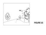
- FIGS. 2A-2Care example conceptual illustrations of determining a state of a traffic intersection.
- FIGS. 2A-2Cillustrate a top view of a vehicle 200 and two perspective views from a position of the vehicle 200 .
- the vehicle 200may scan a target area to determine information associated with a state of a traffic intersection.
- information within a field of view 202 of the vehicle 200may be obtained.
- an imaging component and/or radar component of the vehiclemay be used to obtain information within the field of view 202 .
- the imaging component and radar componentmay be mounted behind or adjacent to a rear-view mirror, such that in a scenario in which the vehicle 200 includes a driver and/or passenger(s), the imaging component or radar component minimally obstructs a field of view of the driver and/or passenger(s). In another scenario, the imaging component and/or the radar component may be mounted on the top of the vehicle 200 .
- the vehicle 200may obtain an image of an area 204 B.
- the imagemay include 2D and/or 3D information.
- the area 204 Bmay include one or more traffic signals and may optionally be predetermined based on known locations of traffic signals and a location and orientation of the vehicle 200 .
- the clarity of an image of the area 204 Bmay be affected by lighting conditions. As shown in FIG. 2B , the position of the sun may be located behind a position of a traffic signal at some times of the day. This may lead to an uncertainty that is higher than uncertainties for other times of the day when the clarity of the image is not affected by the position of the sun.
- an image of an area 204 Cmay also be obstructed by physical objects.
- a tree limbmay obstruct a portion of a traffic signal in an image of the area 204 C.
- a 3D image of the area 204 Cmay reveal objects at multiple distances from the position of the vehicle in a region for which a traffic signal is expected.
- a first distancemay be determined to a point in the area 204 C that is closer to the vehicle than a group of points in the area 204 C that are in the shape of a portion of a traffic signal. This may be indicative of an object that is obstructing a view of the traffic signal.
- a high uncertaintymay be determined for instances in which an object is obstructing a view of the traffic signal.
- respective states of multiple traffic signals of a traffic intersectionmay be determined.
- two or more traffic signalsmay control a flow of traffic for two or more lanes of vehicles moving in a given direction.
- an uncertainty associated with a state of the traffic intersectionmay be determined based on the multiple states.
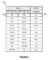
- FIG. 3is an example state table 300 for determining an uncertainty associated with a state of a traffic intersection.
- the state table 300may indicate an uncertainty that is determined for given states of a traffic signal A and a traffic signal B.
- the traffic signal A and the traffic signal Bmay control the flow of traffic for two adjacent lanes of travel which follow the same path through a traffic intersection.
- an output 304 of a low uncertaintymay be determined.
- a state of a first traffic signal for a current lane of the vehiclemay be green, and a state of another traffic signal for an adjacent lane may be red.
- a high uncertaintymay be determined.
- the determined uncertaintymay be high such that the behavior of the vehicle is modified in a conservative manner (e.g., preventing a dangerous crossing of a traffic intersection).
- an uncertainty associated with a determined state of a traffic intersectionmay be weighted by an implication of a meaning of the determined state. For instance, given that two lanes of traffic which follow the same path through a traffic intersection are often controlled in a similar manner, the scenario in which a determined state of a first traffic signal is red and a determined state of a second traffic signal is green is unlikely to occur. If any information indicates that a state of an adjacent traffic signal may be red while a determined state of a first traffic signal is green, a high uncertainty may be determined for the state of the traffic intersection, and the vehicle may determine additional information about the state of the traffic intersection. In some examples, if a vehicle has any uncertainty at all about a state of a traffic intersection, it may be better to stop or slow the vehicle in order to determine additional information prior to proceeding through the traffic intersection, and control of the vehicle may be modified accordingly.
- a state of traffic signal A or a state of traffic signal Bis unknown, a high uncertainty may be determined.
- a scenario in which a state of a traffic signal is undetectablemay imply that information associated with the traffic intersection has changed. For example, a location of a traffic signal may have been moved. Given the high uncertainty, control of the vehicle may be modified to determine additional information about the state of the traffic intersection.
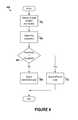
- FIG. 4is an example flow chart 400 for determining a state of a traffic intersection.
- a state of a traffic intersectionmay be determined.
- an autonomous vehiclemay use information from one or more sensors to determine a state of a traffic signal, or determine a vehicle having precedence at a four-way stop.
- an uncertainty associated with the determined state of the traffic intersectionmay be determined.
- the uncertaintymay be an amount of clarity of a state of a traffic signal within an image.
- the uncertaintymay be based on an amount of noise of a sensor, or a historical ability to determine a state of a traffic intersection using information associated with a traffic signal or traffic sign.
- a determinationmay be made whether the determined uncertainty is greater than a predetermined uncertainty threshold.
- the determined statemay be selected by a processing component of the vehicle as the state of the traffic intersection. This may be likened to selecting a presumed state of the traffic intersection as a state of the traffic intersection, and controlling the behavior of the vehicle based on the presumed state.
- a different state than the determined state of the traffic intersectionmay be selected by the processing component. For example, the processing component may defer to a different state due to the determined uncertainty associated with the determined state. In some instances, the different state of the traffic intersection may be a more restrictive or conservative state than the determined state of the traffic intersection.
- a state of a traffic signalmay be detected to determine the state of the traffic intersection, and the state of the traffic signal may be green.
- a presumed state of the traffic intersectionmay be that traffic is flowing through the traffic intersection via a path in which the vehicle is located.
- the determined state of the traffic signalmay include an amount of uncertainty that is greater than the threshold. Accordingly, a more restrictive state than the presumed state may be selected, and control of the vehicle may be modified based on the determined uncertainty such that the vehicle stops or slows down and determines additional information associated with the state of the traffic intersection before proceeding according to the presumed state and traveling through the traffic intersection.
- a determined state of a traffic signalis green and an uncertainty associated with the determined state is high, a presumed state of yellow or red may be selected.
- FIGS. 5A-5Bare example conceptual illustrations of controlling a vehicle.
- a traffic intersectionmay be controlled by a traffic signal 500 .
- a vehicle 502may determine a state of the traffic signal 500 to determine a state of the traffic intersection. Additionally, an uncertainty associated with a determined state of the traffic signal 500 and associated traffic intersection may be determined. In some instances, control of the vehicle may be modified based on the determined state and the determined uncertainty.
- the vehicle 502may move in a direction 504 to an adjusted position. For example, the vehicle 502 may move slowly towards the traffic intersection. While the vehicle 502 is moving, the vehicle 502 may determine additional information associated with the intersection using one or more sensors of the vehicle 502 . In some examples, the information may identify behavior of other vehicles, such as cross traffic approaching or traveling through an intersection. Based on the additional information, the vehicle 502 may re-determine the state of the traffic intersection. For example, if cross traffic is not stopping or yielding, the vehicle may stop or yield.
- the vehicle 502may tap into a network of the traffic signal or multiple traffic signals to determine information about the state of the traffic intersection. For example, if an uncertainty associated with a traffic intersection is high, the vehicle 502 may communicate with a network via a wireless link 506 between the network and a wireless communication system of the vehicle 502 . For example, the vehicle 502 may communicate with a computing system of the traffic signal via the wireless link 506 . In one example, the vehicle 502 may receive information about the state of a traffic signal(s) via the wireless link 506 and compare the received information with the determined state of the traffic signal.
- the wireless communication systemmay include an antenna and a chipset for communicating with other vehicles, sensors, or other entities either directly or via a communication network.
- the chipset or wireless communication systemin general may be arranged to communicate according to one or more other types of wireless communication (e.g., protocols) such as Bluetooth, communication protocols described in IEEE 802.11 (including any IEEE 802.11 revisions), cellular technology (such as GSM, CDMA, UMTS, EV-DO, WiMAX, or LTE), Zigbee, dedicated short range communications (DSRC), and radio frequency identification (RFID) communications, among other possibilities.
- the wireless communication systemmay take other forms as well.
- an example systemmay be implemented in or may take the form of a vehicle.
- the vehiclemay take a number of forms, including, for example, automobiles, cars, trucks, motorcycles, buses, boats, airplanes, helicopters, lawn mowers, earth movers, snowmobiles, recreational vehicles, amusement park vehicles, farm equipment, construction equipment, trams, golf carts, trains, and trolleys. Other vehicles are possible as well.
- another example systemmay take the form of non-transitory computer-readable medium, which has program instructions stored thereon that are executable by at least one processor to provide the functionality described herein.
- An example systemmay also take the form of a vehicle or a subsystem of a vehicle that includes such a non-transitory computer-readable medium having such program instructions stored thereon.
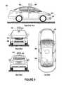
- FIG. 6illustrates an example vehicle 600 , in accordance with an embodiment.
- FIG. 6shows a Right Side View, Front View, Back View, and Top View of the vehicle 600 .
- vehicle 600is illustrated in FIG. 6 as a car, other embodiments are possible.
- the vehicle 600could represent a truck, a van, a semi-trailer truck, a motorcycle, a golf cart, an off-road vehicle, or a farm vehicle, among other examples.
- the vehicle 600includes a first sensor unit 602 , a second sensor unit 604 , a third sensor unit 606 , a wireless communication system 608 , and a camera 610 .
- Each of the first, second, and third sensor units 602 - 606may include any combination of global positioning system sensors, inertial measurement units, radio detection and ranging (RADAR) units, laser rangefinders, light detection and ranging (LIDAR) units, cameras, and acoustic sensors. Other types of sensors are possible as well.
- RADARradio detection and ranging
- LIDARlight detection and ranging
- first, second, and third sensor units 602are shown to be mounted in particular locations on the vehicle 600 , in some embodiments the sensor unit 602 may be mounted elsewhere on the vehicle 600 , either inside or outside the vehicle 600 . Further, while only three sensor units are shown, in some embodiments more or fewer sensor units may be included in the vehicle 600 .
- one or more of the first, second, and third sensor units 602 - 606may include one or more movable mounts on which the sensors may be movably mounted.
- the movable mountmay include, for example, a rotating platform. Sensors mounted on the rotating platform could be rotated so that the sensors may obtain information from each direction around the vehicle 600 .
- the movable mountmay include a tilting platform. Sensors mounted on the tilting platform could be tilted within a particular range of angles and/or azimuths so that the sensors may obtain information from a variety of angles.
- the movable mountmay take other forms as well.
- one or more of the first, second, and third sensor units 602 - 606may include one or more actuators configured to adjust the position and/or orientation of sensors in the sensor unit by moving the sensors and/or movable mounts.
- Example actuatorsinclude motors, pneumatic actuators, hydraulic pistons, relays, solenoids, and piezoelectric actuators. Other actuators are possible as well.
- the wireless communication system 608may be any system configured to wirelessly couple to one or more other vehicles, sensors, or other entities, either directly or via a communication network.
- the wireless communication system 608may include an antenna and a chipset for communicating with the other vehicles, sensors, or other entities either directly or via a communication network.
- the chipset or wireless communication system 608in general may be arranged to communicate according to one or more other types of wireless communication (e.g., protocols) such as Bluetooth, communication protocols described in IEEE 802.11 (including any IEEE 802.11 revisions), cellular technology (such as GSM, CDMA, UMTS, EV-DO, WiMAX, or LTE), Zigbee, dedicated short range communications (DSRC), and radio frequency identification (RFID) communications, among other possibilities.
- the wireless communication system 608may take other forms as well.
- wireless communication system 608is shown positioned on a roof of the vehicle 600 , in other embodiments the wireless communication system 608 could be located, fully or in part, elsewhere.
- the camera 610may be any camera (e.g., a still camera, a video camera, etc.) configured to capture images of the environment in which the vehicle 600 is located. To this end, the camera 610 may be configured to detect visible light, or may be configured to detect light from other portions of the spectrum, such as infrared or ultraviolet light. Other types of cameras are possible as well.
- the camera 610may be a two-dimensional detector, or may have a three-dimensional spatial range. In some embodiments, the camera 610 may be, for example, a range detector configured to generate a two-dimensional image indicating a distance from the camera 610 to a number of points in the environment. To this end, the camera 610 may use one or more range detecting techniques.
- the camera 610may use a structured light technique in which the vehicle 600 illuminates an object in the environment with a predetermined light pattern, such as a grid or checkerboard pattern and uses the camera 610 to detect a reflection of the predetermined light pattern off the object. Based on distortions in the reflected light pattern, the vehicle 600 may determine the distance to the points on the object.
- the predetermined light patternmay comprise infrared light, or light of another wavelength.
- the camera 610may use a laser scanning technique in which the vehicle 600 emits a laser and scans across a number of points on an object in the environment. While scanning the object, the vehicle 600 uses the camera 610 to detect a reflection of the laser off the object for each point.
- the vehicle 600may determine the distance to the points on the object.
- the camera 610may use a time-of-flight technique in which the vehicle 600 emits a light pulse and uses the camera 610 to detect a reflection of the light pulse off an object at a number of points on the object.
- the camera 610may include a number of pixels, and each pixel may detect the reflection of the light pulse from a point on the object.
- the vehicle 600may determine the distance to the points on the object.
- the light pulsemay be a laser pulse.
- Other range detecting techniquesare possible as well, including stereo triangulation, sheet-of-light triangulation, interferometry, and coded aperture techniques, among others.
- the camera 610may take other forms as well.
- the camera 610may include a movable mount and/or an actuator, as described above, that are configured to adjust the position and/or orientation of the camera 610 by moving the camera 610 and/or the movable mount.
- the camera 610is shown to be mounted inside a front windshield of the vehicle 600 , in other embodiments the camera 610 may be mounted elsewhere on the vehicle 600 , either inside or outside the vehicle 600 .
- the vehicle 600may include one or more other components in addition to or instead of those shown.
- FIG. 7is a simplified block diagram of an example vehicle 700 , in accordance with an embodiment.
- the vehicle 700may, for example, be similar to the vehicle 600 described above in connection with FIG. 6 .
- the vehicle 700may take other forms as well.
- the vehicle 700includes a propulsion system 702 , a sensor system 704 , a control system 706 , peripherals 708 , and a computer system 710 including a processor 712 , data storage 714 , and instructions 716 .
- the vehicle 700may include more, fewer, or different systems, and each system may include more, fewer, or different components. Additionally, the systems and components shown may be combined or divided in any number of ways.
- the propulsion system 702may be configured to provide powered motion for the vehicle 700 .
- the propulsion system 702includes an engine/motor 718 , an energy source 720 , a transmission 722 , and wheels/tires 724 .
- the engine/motor 718may be or include any combination of an internal combustion engine, an electric motor, a steam engine, and a Stirling engine. Other motors and engines are possible as well.
- the propulsion system 702could include multiple types of engines and/or motors.
- a gas-electric hybrid carcould include a gasoline engine and an electric motor. Other examples are possible.
- the energy source 720may be a source of energy that powers the engine/motor 718 in full or in part. That is, the engine/motor 718 may be configured to convert the energy source 720 into mechanical energy. Examples of energy sources 720 include gasoline, diesel, propane, other compressed gas-based fuels, ethanol, solar panels, batteries, and other sources of electrical power. The energy source(s) 720 could additionally or alternatively include any combination of fuel tanks, batteries, capacitors, and/or flywheels. In some embodiments, the energy source 720 may provide energy for other systems of the vehicle 700 as well.
- the transmission 722may be configured to transmit mechanical power from the engine/motor 718 to the wheels/tires 724 .
- the transmission 722may include a gearbox, clutch, differential, drive shafts, and/or other elements.
- the drive shaftscould include one or more axles that are configured to be coupled to the wheels/tires 724 .
- the wheels/tires 724 of vehicle 700could be configured in various formats, including a unicycle, bicycle/motorcycle, tricycle, or car/truck four-wheel format. Other wheel/tire formats are possible as well, such as those including six or more wheels. In any case, the wheels/tires 724 of vehicle 700 may be configured to rotate differentially with respect to other wheels/tires 724 . In some embodiments, the wheels/tires 724 may include at least one wheel that is fixedly attached to the transmission 722 and at least one tire coupled to a rim of the wheel that could make contact with the driving surface. The wheels/tires 724 may include any combination of metal and rubber, or combination of other materials.
- the propulsion system 702may additionally or alternatively include components other than those shown.
- the sensor system 704may include a number of sensors configured to sense information about an environment in which the vehicle 700 is located, as well as one or more actuators 736 configured to modify a position and/or orientation of the sensors.
- the sensors of the sensor systeminclude a Global Positioning System (GPS) 726 , an inertial measurement unit (IMU) 728 , a RADAR unit 730 , a laser rangefinder and/or LIDAR unit 732 , and a camera 734 .
- the sensor system 704may include additional sensors as well, including, for example, sensors that monitor internal systems of the vehicle 700 (e.g., an O 2 monitor, a fuel gauge, an engine oil temperature, etc.). Other sensors are possible as well.
- the GPS 726may be any sensor configured to estimate a geographic location of the vehicle 700 .
- the GPS 726may include a transceiver configured to estimate a position of the vehicle 700 with respect to the Earth.
- the GPS 726may take other forms as well.
- the IMU 728may be any combination of sensors configured to sense position and orientation changes of the vehicle 700 based on inertial acceleration.
- the combination of sensorsmay include, for example, accelerometers and gyroscopes. Other combinations of sensors are possible as well.
- the RADAR 730 unitmay be any sensor configured to sense objects in the environment in which the vehicle 700 is located using radio signals. In some embodiments, in addition to sensing the objects, the RADAR unit 730 may additionally be configured to sense the speed and/or heading of the objects.
- the laser rangefinder or LIDAR unit 732may be any sensor configured to sense objects in the environment in which the vehicle 700 is located using lasers.
- the laser rangefinder or LIDAR unit 732may include a laser source and/or laser scanner configured to emit a laser and a detector configured to detect reflections of the laser.
- the laser rangefinder or LIDAR 732may be configured to operate in a coherent (e.g., using heterodyne detection) or an incoherent detection mode.
- the camera 734may be any camera (e.g., a still camera, a video camera, etc.) configured to capture images of the environment in which the vehicle 700 is located. To this end, the camera may take any of the forms described above.
- the sensor system 704may additionally or alternatively include components other than those shown.
- the control system 706may be configured to control operation of the vehicle 700 and its components. To this end, the control system 706 may include a steering unit 738 , a throttle 740 , a brake unit 742 , a sensor fusion algorithm 744 , a computer vision system 746 , a navigation or pathing system 748 , and an obstacle avoidance system 750 .
- the steering unit 738may be any combination of mechanisms configured to adjust the heading of vehicle 700 .
- the throttle 740may be any combination of mechanisms configured to control the operating speed of the engine/motor 718 and, in turn, the speed of the vehicle 700 .
- the brake unit 742may be any combination of mechanisms configured to decelerate the vehicle 700 .
- the brake unit 742may use friction to slow the wheels/tires 724 .
- the brake unit 742may convert the kinetic energy of the wheels/tires 724 to electric current.
- the brake unit 742may take other forms as well.
- the sensor fusion algorithm 744may be an algorithm (or a computer program product storing an algorithm) configured to accept data from the sensor system 704 as an input.
- the datamay include, for example, data representing information sensed at the sensors of the sensor system 704 .
- the sensor fusion algorithm 744may include, for example, a Kalman filter, a Bayesian network, or another algorithm.
- the sensor fusion algorithm 744may further be configured to provide various assessments based on the data from the sensor system 704 , including, for example, evaluations of individual objects and/or features in the environment in which the vehicle 700 is located, evaluations of particular situations, and/or evaluations of possible impacts based on particular situations. Other assessments are possible as well.
- the computer vision system 746may be any system configured to process and analyze images captured by the camera 734 in order to identify objects and/or features in the environment in which the vehicle 700 is located, including, for example, traffic signals and obstacles. To this end, the computer vision system 746 may use an object recognition algorithm, a Structure from Motion (SFM) algorithm, video tracking, or other computer vision techniques. In some embodiments, the computer vision system 746 may additionally be configured to map the environment, track objects, estimate the speed of objects, etc.
- SFMStructure from Motion
- the navigation and pathing system 748may be any system configured to determine a driving path for the vehicle 700 .
- the navigation and pathing system 748may additionally be configured to update the driving path dynamically while the vehicle 700 is in operation.
- the navigation and pathing system 748may be configured to incorporate data from the sensor fusion algorithm 744 , the GPS 726 , and one or more predetermined maps so as to determine the driving path for vehicle 100 .
- the obstacle avoidance system 750may be any system configured to identify, evaluate, and avoid or otherwise negotiate obstacles in the environment in which the vehicle 700 is located.
- the control system 706may additionally or alternatively include components other than those shown.
- Peripherals 708may be configured to allow the vehicle 700 to interact with external sensors, other vehicles, and/or a user.
- the peripherals 708may include, for example, a wireless communication system 752 , a touchscreen 754 , a microphone 756 , and/or a speaker 758 .
- the wireless communication system 752may take any of the forms described above.
- the touchscreen 754may be used by a user to input commands to the vehicle 700 .
- the touchscreen 754may be configured to sense at least one of a position and a movement of a user's finger via capacitive sensing, resistance sensing, or a surface acoustic wave process, among other possibilities.
- the touchscreen 754may be capable of sensing finger movement in a direction parallel or planar to the touchscreen surface, in a direction normal to the touchscreen surface, or both, and may also be capable of sensing a level of pressure applied to the touchscreen surface.
- the touchscreen 754may be formed of one or more translucent or transparent insulating layers and one or more translucent or transparent conducting layers.
- the touchscreen 754may take other forms as well.
- the microphone 756may be configured to receive audio (e.g., a voice command or other audio input) from a user of the vehicle 700 .
- the speakers 758may be configured to output audio to the user of the vehicle 700 .
- the peripherals 708may additionally or alternatively include components other than those shown.
- the computer system 710may be configured to transmit data to and receive data from one or more of the propulsion system 702 , the sensor system 704 , the control system 706 , and the peripherals 708 .
- the computer system 710may be communicatively linked to one or more of the propulsion system 702 , the sensor system 704 , the control system 706 , and the peripherals 708 by a system bus, network, and/or other connection mechanism (not shown).
- the computer system 710may be further configured to interact with and control one or more components of the propulsion system 702 , the sensor system 704 , the control system 706 , and/or the peripherals 708 .
- the computer system 710may be configured to control operation of the transmission 722 to improve fuel efficiency.
- the computer system 710may be configured to cause the camera 734 to capture images of the environment.
- the computer system 710may be configured to store and execute instructions corresponding to the sensor fusion algorithm 744 .
- the computer system 710may be configured to store and execute instructions for displaying a display on the touchscreen 754 . Other examples are possible as well.
- the computer system 710includes the processor 712 and data storage 714 .
- the processor 712may comprise one or more general-purpose processors and/or one or more special-purpose processors. To the extent the processor 712 includes more than one processor, such processors could work separately or in combination.
- Data storage 714may comprise one or more volatile and/or one or more non-volatile storage components, such as optical, magnetic, and/or organic storage, and data storage 714 may be integrated in whole or in part with the processor 712 .
- data storage 714may contain instructions 716 (e.g., program logic) executable by the processor 712 to execute various vehicle functions, including those described above in connection with FIG. 1 . Further, data storage 714 may contain constraints 717 for the vehicle 700 , which may take any of the forms described above. Data storage 714 may contain additional instructions as well, including instructions to transmit data to, receive data from, interact with, and/or control one or more of the propulsion system 702 , the sensor system 704 , the control system 706 , and the peripherals 708 .
- instructions 716e.g., program logic
- data storage 714may contain constraints 717 for the vehicle 700 , which may take any of the forms described above.
- Data storage 714may contain additional instructions as well, including instructions to transmit data to, receive data from, interact with, and/or control one or more of the propulsion system 702 , the sensor system 704 , the control system 706 , and the peripherals 708 .
- the computer system 702may additionally or alternatively include components other than those shown.
- the vehicle 700further includes a power supply 760 , which may be configured to provide power to some or all of the components of the vehicle 700 .
- the power supply 760may include, for example, a rechargeable lithium-ion or lead-acid battery. In some embodiments, one or more banks of batteries could be configured to provide electrical power. Other power supply materials and configurations are possible as well.
- the power supply 760 and energy source 720may be implemented together, as in some all-electric cars.
- one or more of the propulsion system 702 , the sensor system 704 , the control system 706 , and the peripherals 708could be configured to work in an interconnected fashion with other components within and/or outside their respective systems.
- vehicle 700may include one or more elements in addition to or instead of those shown.
- vehicle 700may include one or more additional interfaces and/or power supplies.
- data storage 714may further include instructions executable by the processor 712 to control and/or communicate with the additional components.
- one or more components or systemsmay be removably mounted on or otherwise connected (mechanically or electrically) to the vehicle 700 using wired or wireless connections.
- the vehicle 700may take other forms as well.
- FIG. 8is a schematic illustrating a conceptual partial view of an example computer program product 800 that includes a computer program for executing a computer process on a computing device, arranged according to at least some embodiments presented herein.
- the example computer program product 800is provided using a signal bearing medium 802 .
- the signal bearing medium 802may include one or more programming instructions 804 that, when executed by one or more processors, may provide functionality or portions of the functionality described above with respect to FIGS. 1-7 .
- the signal bearing medium 802may encompass a computer-readable medium 806 , such as, but not limited to, a hard disk drive, a Compact Disc (CD), a Digital Video Disk (DVD), a digital tape, memory, etc. Further, in some embodiments the signal bearing medium 802 may encompass a computer recordable medium 808 , such as, but not limited to, memory, read/write (R/W) CDs, R/W DVDs, etc. Still further, in some embodiments the signal bearing medium 802 may encompass a communications medium 810 , such as, but not limited to, a digital and/or an analog communication medium (e.g., a fiber optic cable, a waveguide, a wired communications link, a wireless communication link, etc.). Thus, for example, the signal bearing medium 802 may be conveyed by a wireless form of the communications medium 810 .
- a computer-readable medium 806such as, but not limited to, a hard disk drive, a Compact Disc (CD), a Digital Video Disk (
- the one or more programming instructions 804may be, for example, computer executable and/or logic implemented instructions.
- a computing systemsuch as the computing system 710 of FIG. 7 may be configured to provide various operations, functions, or actions in response to the programming instructions 804 being conveyed to the computing system 710 by one or more of the computer readable medium 806 , the computer recordable medium 808 , and/or the communications medium 810 .
Landscapes
- Engineering & Computer Science (AREA)
- Physics & Mathematics (AREA)
- General Physics & Mathematics (AREA)
- Life Sciences & Earth Sciences (AREA)
- Atmospheric Sciences (AREA)
- Automation & Control Theory (AREA)
- Transportation (AREA)
- Mechanical Engineering (AREA)
- Business, Economics & Management (AREA)
- Health & Medical Sciences (AREA)
- Artificial Intelligence (AREA)
- Evolutionary Computation (AREA)
- Game Theory and Decision Science (AREA)
- Medical Informatics (AREA)
- Aviation & Aerospace Engineering (AREA)
- Radar, Positioning & Navigation (AREA)
- Remote Sensing (AREA)
- Traffic Control Systems (AREA)
Abstract
Description
Claims (14)
Priority Applications (2)
| Application Number | Priority Date | Filing Date | Title |
|---|---|---|---|
| US13/441,996US8761991B1 (en) | 2012-04-09 | 2012-04-09 | Use of uncertainty regarding observations of traffic intersections to modify behavior of a vehicle |
| US14/288,111US9261879B2 (en) | 2012-04-09 | 2014-05-27 | Use of uncertainty regarding observations of traffic intersections to modify behavior of a vehicle |
Applications Claiming Priority (1)
| Application Number | Priority Date | Filing Date | Title |
|---|---|---|---|
| US13/441,996US8761991B1 (en) | 2012-04-09 | 2012-04-09 | Use of uncertainty regarding observations of traffic intersections to modify behavior of a vehicle |
Related Child Applications (1)
| Application Number | Title | Priority Date | Filing Date |
|---|---|---|---|
| US14/288,111ContinuationUS9261879B2 (en) | 2012-04-09 | 2014-05-27 | Use of uncertainty regarding observations of traffic intersections to modify behavior of a vehicle |
Publications (1)
| Publication Number | Publication Date |
|---|---|
| US8761991B1true US8761991B1 (en) | 2014-06-24 |
Family
ID=50944157
Family Applications (2)
| Application Number | Title | Priority Date | Filing Date |
|---|---|---|---|
| US13/441,996Active2032-07-20US8761991B1 (en) | 2012-04-09 | 2012-04-09 | Use of uncertainty regarding observations of traffic intersections to modify behavior of a vehicle |
| US14/288,111Expired - Fee RelatedUS9261879B2 (en) | 2012-04-09 | 2014-05-27 | Use of uncertainty regarding observations of traffic intersections to modify behavior of a vehicle |
Family Applications After (1)
| Application Number | Title | Priority Date | Filing Date |
|---|---|---|---|
| US14/288,111Expired - Fee RelatedUS9261879B2 (en) | 2012-04-09 | 2014-05-27 | Use of uncertainty regarding observations of traffic intersections to modify behavior of a vehicle |
Country Status (1)
| Country | Link |
|---|---|
| US (2) | US8761991B1 (en) |
Cited By (56)
| Publication number | Priority date | Publication date | Assignee | Title |
|---|---|---|---|---|
| US20140070960A1 (en)* | 2012-09-07 | 2014-03-13 | Electronics And Telecommunications Research Institute | Apparatus for gathering surroundings information of vehicle |
| US9156473B2 (en) | 2013-12-04 | 2015-10-13 | Mobileye Vision Technologies Ltd. | Multi-threshold reaction zone for autonomous vehicle navigation |
| US9272709B2 (en) | 2014-01-30 | 2016-03-01 | Mobileye Vision Technologies Ltd. | Systems and methods for detecting traffic lights |
| WO2016094088A1 (en)* | 2014-12-09 | 2016-06-16 | Toyota Motor Engineering & Manufacturing North America, Inc. | Autonomous vehicle detection of and response to intersection priority |
| US9396657B1 (en)* | 2013-04-12 | 2016-07-19 | Traffic Technology Solutions, LLC | Prediction of traffic signal state changes |
| US20160282879A1 (en)* | 2014-04-30 | 2016-09-29 | Toyota Motor Engineering & Manufacturing North America, Inc. | Detailed map format for autonomous driving |
| WO2016205530A1 (en)* | 2015-06-16 | 2016-12-22 | Fossier David A | Forklift activated security projector |
| EP3133455A1 (en)* | 2015-08-17 | 2017-02-22 | Honda Research Institute Europe GmbH | System for autonomously or partially autonomously driving a vehicle with a communication module for obtaining additional information from a vehicle driver and corresponding method |
| US20170057514A1 (en)* | 2015-08-27 | 2017-03-02 | Toyota Motor Engineering & Manufacturing North America, Inc. | Autonomous vehicle operation at multi-stop intersections |
| EP3176046A1 (en)* | 2015-12-04 | 2017-06-07 | Volkswagen Aktiengesellschaft | Method and device in a motor vehicle for automated driving |
| US20170169706A1 (en)* | 2015-12-14 | 2017-06-15 | Charlotte Arnold | System and Associated Methods for Operating Traffic Signs |
| WO2017153979A1 (en)* | 2016-03-06 | 2017-09-14 | Foresight Automotive Ltd. | Running vehicle alerting system and method |
| US9779314B1 (en) | 2014-08-21 | 2017-10-03 | Waymo Llc | Vision-based detection and classification of traffic lights |
| US9928738B2 (en) | 2013-04-12 | 2018-03-27 | Traffic Technology Services, Inc. | Red light warning system based on predictive traffic signal state data |
| JP2018060563A (en)* | 2017-11-24 | 2018-04-12 | 株式会社ゼンリン | Driving support system, data structure |
| US9953538B1 (en)* | 2017-01-17 | 2018-04-24 | Lyft, Inc. | Autonomous vehicle notification system |
| US10008113B2 (en) | 2013-04-12 | 2018-06-26 | Traffic Technology Services, Inc. | Hybrid distributed prediction of traffic signal state changes |
| WO2018199826A1 (en)* | 2017-04-25 | 2018-11-01 | Husqvarna Ab | Improved reception of frequency spectra on the receiver side |
| US10118614B2 (en) | 2014-04-30 | 2018-11-06 | Toyota Motor Engineering & Manufacturing North America, Inc. | Detailed map format for autonomous driving |
| CN109035831A (en)* | 2018-09-07 | 2018-12-18 | 百度在线网络技术(北京)有限公司 | Recognition methods, device, equipment, storage medium and the vehicle of traffic light |
| WO2019006084A1 (en)* | 2017-06-30 | 2019-01-03 | Delphi Technologies, Inc. | Moving traffic-light detection system for an automated vehicle |
| WO2019018766A1 (en)* | 2017-07-20 | 2019-01-24 | Carnegie Mellon University | System and method for vehicle-actuated traffic control |
| CN109410604A (en)* | 2018-12-25 | 2019-03-01 | 重庆长安汽车股份有限公司 | Traffic lights information acquisition device and method |
| US10336188B2 (en)* | 2017-03-15 | 2019-07-02 | Subaru Corporation | Vehicle display system and method of controlling vehicle display system |
| US10354404B2 (en)* | 2014-11-18 | 2019-07-16 | Lg Electronics Inc. | Electronic device and control method therefor |
| US10366295B2 (en)* | 2014-08-18 | 2019-07-30 | Denso Corporation | Object recognition apparatus |
| US10388173B2 (en)* | 2012-11-19 | 2019-08-20 | Rosemount Aerospace, Inc. | Collision avoidance system for aircraft ground operations |
| US20190286155A1 (en)* | 2016-01-05 | 2019-09-19 | Mobileye Vision Technologies Ltd. | Suboptimal immediate navigational response based on long term planning |
| US20190354105A1 (en)* | 2018-05-15 | 2019-11-21 | Toyota Research Institute, Inc. | Modeling graph of interactions between agents |
| US10509402B1 (en)* | 2013-04-17 | 2019-12-17 | Waymo Llc | Use of detected objects for image processing |
| JP2020024715A (en)* | 2014-07-31 | 2020-02-13 | ウェイモ エルエルシー | Traffic signal response for autonomous vehicles |
| US10691133B1 (en) | 2019-11-26 | 2020-06-23 | Apex Artificial Intelligence Industries, Inc. | Adaptive and interchangeable neural networks |
| US10726719B1 (en)* | 2019-02-05 | 2020-07-28 | International Business Machines Corporation | Piezoelectric power generation for roadways |
| WO2020178098A1 (en)* | 2019-03-07 | 2020-09-10 | Robert Bosch Gmbh | Method for the at least partially automated guidance of a motor vehicle |
| CN111688688A (en)* | 2019-03-13 | 2020-09-22 | 罗伯特·博世有限公司 | Implementation of rollback at a traffic node for a previously traveling vehicle |
| US10823855B2 (en) | 2018-11-19 | 2020-11-03 | Fca Us Llc | Traffic recognition and adaptive ground removal based on LIDAR point cloud statistics |
| US10852420B2 (en)* | 2018-05-18 | 2020-12-01 | Industrial Technology Research Institute | Object detection system, autonomous vehicle using the same, and object detection method thereof |
| CN112289067A (en)* | 2019-07-23 | 2021-01-29 | 丰田自动车株式会社 | Signal Display Estimation System |
| US10909866B2 (en) | 2018-07-20 | 2021-02-02 | Cybernet Systems Corp. | Autonomous transportation system and methods |
| US10956807B1 (en) | 2019-11-26 | 2021-03-23 | Apex Artificial Intelligence Industries, Inc. | Adaptive and interchangeable neural networks utilizing predicting information |
| US11069236B2 (en) | 2017-10-05 | 2021-07-20 | Carnegie Mellon University | Systems and methods for virtual traffic lights implemented on a mobile computing device |
| CN114179822A (en)* | 2020-09-15 | 2022-03-15 | 大众汽车股份公司 | Method, computer program and apparatus for controlling the operation of a vehicle equipped with automated driving functions |
| US20220101723A1 (en)* | 2020-09-30 | 2022-03-31 | Nissan North America, Inc. | Annotation and Mapping for Vehicle Operation in Low-Confidence Object Detection Conditions |
| US11307582B2 (en)* | 2018-03-13 | 2022-04-19 | Honda Motor Co., Ltd. | Vehicle control device, vehicle control method and storage medium |
| US11334753B2 (en) | 2018-04-30 | 2022-05-17 | Uatc, Llc | Traffic signal state classification for autonomous vehicles |
| US11366434B2 (en) | 2019-11-26 | 2022-06-21 | Apex Artificial Intelligence Industries, Inc. | Adaptive and interchangeable neural networks |
| US11366472B1 (en) | 2017-12-29 | 2022-06-21 | Apex Artificial Intelligence Industries, Inc. | Apparatus and method for monitoring and controlling of a neural network using another neural network implemented on one or more solid-state chips |
| US11367290B2 (en) | 2019-11-26 | 2022-06-21 | Apex Artificial Intelligence Industries, Inc. | Group of neural networks ensuring integrity |
| US20220242423A1 (en)* | 2019-07-15 | 2022-08-04 | Valeo Schalter Und Sensoren Gmbh | Determining a signal state of a traffic light device |
| US11462022B2 (en)* | 2016-03-09 | 2022-10-04 | Uatc, Llc | Traffic signal analysis system |
| US11480977B2 (en)* | 2019-11-25 | 2022-10-25 | Gm Cruise Holdings Llc | Sharing sensor data to assist in maneuvering of an autonomous vehicle |
| US20240038065A1 (en)* | 2022-07-28 | 2024-02-01 | Motional Ad Llc | Managing traffic light detections |
| US20240075961A1 (en)* | 2012-06-01 | 2024-03-07 | Waymo Llc | Inferring State of Traffic Signal and Other Aspects of a Vehicle's Environment Based on Surrogate Data |
| US12081646B2 (en) | 2019-11-26 | 2024-09-03 | Apex Ai Industries, Llc | Adaptively controlling groups of automated machines |
| US12330645B2 (en)* | 2020-07-07 | 2025-06-17 | Denso Corporation | Control device, control method, and control program product |
| US12387600B2 (en) | 2017-10-05 | 2025-08-12 | Carnegie Mellon University | Methods and systems for self-organized traffic management at intersections using a distributed AI approach |
Families Citing this family (27)
| Publication number | Priority date | Publication date | Assignee | Title |
|---|---|---|---|---|
| US9566982B2 (en) | 2009-06-16 | 2017-02-14 | Tomtom North America, Inc. | Methods and systems for generating a horizon for use in an advanced driver assistance system (ADAS) |
| EP2443418B1 (en)* | 2009-06-16 | 2018-12-05 | TomTom North America Inc. | Methods and systems for creating digital street network database |
| GB201219742D0 (en) | 2012-11-02 | 2012-12-12 | Tom Tom Int Bv | Methods and systems for generating a horizon for use in an advanced driver assistance system (adas) |
| US9092986B2 (en)* | 2013-02-04 | 2015-07-28 | Magna Electronics Inc. | Vehicular vision system |
| US10275669B2 (en)* | 2015-09-09 | 2019-04-30 | Lightmetrics Technologies Pvt. Ltd. | System and method for detecting objects in an automotive environment |
| US10190560B2 (en) | 2016-06-03 | 2019-01-29 | Magna Electronics Inc. | Camera based vehicle start-stop feature |
| CN105946855A (en)* | 2016-06-21 | 2016-09-21 | 周弘来 | System and method controlling waiting vehicles to start simultaneously so as to increase intersection passing efficiency |
| US10102747B2 (en) | 2016-08-10 | 2018-10-16 | Toyota Motor Engineering & Manufacturing North America, Inc. | Intersection traffic signal indicator systems and methods for vehicles |
| US10276043B2 (en)* | 2016-12-22 | 2019-04-30 | GM Global Technology Operations LLC | Vehicle system using vehicle-to-infrastructure and sensor information |
| WO2018191117A1 (en)* | 2017-04-12 | 2018-10-18 | Hrl Laboratories, Llc | Cognitive behavior prediction system for autonomous systems |
| CN113665570A (en) | 2017-04-18 | 2021-11-19 | 动态Ad有限责任公司 | Method and device for automatically sensing driving signal and vehicle |
| US10643084B2 (en) | 2017-04-18 | 2020-05-05 | nuTonomy Inc. | Automatically perceiving travel signals |
| CN107346611B (en)* | 2017-07-20 | 2021-03-23 | 北京纵目安驰智能科技有限公司 | Obstacle avoidance method and obstacle avoidance system for autonomous driving vehicle |
| CN107703911B (en)* | 2017-09-05 | 2019-06-18 | 北京控制工程研究所 | A Diagnosis Analysis Method for Uncertain Systems |
| US10719705B2 (en) | 2018-01-03 | 2020-07-21 | Qualcomm Incorporated | Adjustable object avoidance proximity threshold based on predictability of the environment |
| US10717435B2 (en) | 2018-01-03 | 2020-07-21 | Qualcomm Incorporated | Adjustable object avoidance proximity threshold based on classification of detected objects |
| US10636314B2 (en) | 2018-01-03 | 2020-04-28 | Qualcomm Incorporated | Adjusting flight parameters of an aerial robotic vehicle based on presence of propeller guard(s) |
| US10720070B2 (en) | 2018-01-03 | 2020-07-21 | Qualcomm Incorporated | Adjustable object avoidance proximity threshold of a robotic vehicle based on presence of detected payload(s) |
| US10803759B2 (en) | 2018-01-03 | 2020-10-13 | Qualcomm Incorporated | Adjustable object avoidance proximity threshold based on presence of propeller guard(s) |
| RU2770716C1 (en)* | 2018-07-04 | 2022-04-21 | Ниссан Мотор Ко., Лтд. | Method for driving assistance and apparatus for driving assistance |
| CN109147352B (en)* | 2018-11-02 | 2021-11-23 | 安徽安凯汽车股份有限公司 | Control system and method for safe and intelligent driving of automobile traffic light zebra crossing |
| US20200192393A1 (en)* | 2018-12-12 | 2020-06-18 | Allstate Insurance Company | Self-Modification of an Autonomous Driving System |
| JP2020106961A (en)* | 2018-12-26 | 2020-07-09 | トヨタ自動車株式会社 | Traffic light determination device |
| US10960886B2 (en) | 2019-01-29 | 2021-03-30 | Motional Ad Llc | Traffic light estimation |
| KR102767292B1 (en)* | 2020-07-02 | 2025-02-17 | 현대자동차주식회사 | Vehicle control system using reliablility of input signal for autonomous vehicle |
| US11623639B2 (en)* | 2020-07-15 | 2023-04-11 | Charter Communications Operating, Llc | Video analytics traffic monitoring and control |
| US12361825B2 (en)* | 2021-09-20 | 2025-07-15 | Deere & Company | Traffic signal systems for communicating with vehicle sensors |
Citations (6)
| Publication number | Priority date | Publication date | Assignee | Title |
|---|---|---|---|---|
| US6728623B2 (en)* | 2000-02-23 | 2004-04-27 | Hitachi, Ltd. | Running control device for a vehicle |
| US20080162027A1 (en) | 2006-12-29 | 2008-07-03 | Robotic Research, Llc | Robotic driving system |
| US20090303077A1 (en) | 2006-03-06 | 2009-12-10 | Hirohisa Onome | Image Processing System and Method |
| US20100106356A1 (en)* | 2008-10-24 | 2010-04-29 | The Gray Insurance Company | Control and systems for autonomously driven vehicles |
| US7979172B2 (en) | 1997-10-22 | 2011-07-12 | Intelligent Technologies International, Inc. | Autonomous vehicle travel control systems and methods |
| US20110182475A1 (en) | 2010-01-22 | 2011-07-28 | Google Inc. | Traffic signal mapping and detection |
Family Cites Families (1)
| Publication number | Priority date | Publication date | Assignee | Title |
|---|---|---|---|---|
| US8774523B2 (en)* | 2009-07-28 | 2014-07-08 | Schlumberger Technology Corporation | Precise boundary segment intersection for boundary representation modeling |
- 2012
- 2012-04-09USUS13/441,996patent/US8761991B1/enactiveActive
- 2014
- 2014-05-27USUS14/288,111patent/US9261879B2/ennot_activeExpired - Fee Related
Patent Citations (6)
| Publication number | Priority date | Publication date | Assignee | Title |
|---|---|---|---|---|
| US7979172B2 (en) | 1997-10-22 | 2011-07-12 | Intelligent Technologies International, Inc. | Autonomous vehicle travel control systems and methods |
| US6728623B2 (en)* | 2000-02-23 | 2004-04-27 | Hitachi, Ltd. | Running control device for a vehicle |
| US20090303077A1 (en) | 2006-03-06 | 2009-12-10 | Hirohisa Onome | Image Processing System and Method |
| US20080162027A1 (en) | 2006-12-29 | 2008-07-03 | Robotic Research, Llc | Robotic driving system |
| US20100106356A1 (en)* | 2008-10-24 | 2010-04-29 | The Gray Insurance Company | Control and systems for autonomously driven vehicles |
| US20110182475A1 (en) | 2010-01-22 | 2011-07-28 | Google Inc. | Traffic signal mapping and detection |
Non-Patent Citations (1)
| Title |
|---|
| Teichman, Alex, "Towards 3D Object Recognition via Classification of Arbitrary Object Tracks", International Conference on Robotics and Automation (ICRA), May 9-13, 2011, p. 4034-4041. |
Cited By (110)
| Publication number | Priority date | Publication date | Assignee | Title |
|---|---|---|---|---|
| US12428035B2 (en)* | 2012-06-01 | 2025-09-30 | Waymo Llc | Inferring state of traffic signal and other aspects of a vehicle's environment based on surrogate data |
| US20240075961A1 (en)* | 2012-06-01 | 2024-03-07 | Waymo Llc | Inferring State of Traffic Signal and Other Aspects of a Vehicle's Environment Based on Surrogate Data |
| US20140070960A1 (en)* | 2012-09-07 | 2014-03-13 | Electronics And Telecommunications Research Institute | Apparatus for gathering surroundings information of vehicle |
| US9230441B2 (en)* | 2012-09-07 | 2016-01-05 | Electronics And Telecommunications Research Institute | Apparatus for gathering surroundings information of vehicle |
| US10388173B2 (en)* | 2012-11-19 | 2019-08-20 | Rosemount Aerospace, Inc. | Collision avoidance system for aircraft ground operations |
| US10008113B2 (en) | 2013-04-12 | 2018-06-26 | Traffic Technology Services, Inc. | Hybrid distributed prediction of traffic signal state changes |
| US10140862B2 (en)* | 2013-04-12 | 2018-11-27 | Traffic Technology Services, Inc. | Hybrid distributed prediction of traffic signal state changes |
| US10192436B2 (en)* | 2013-04-12 | 2019-01-29 | Traffic Technology Services, Inc. | Red light warning system based on predictive traffic signal state data |
| US9396657B1 (en)* | 2013-04-12 | 2016-07-19 | Traffic Technology Solutions, LLC | Prediction of traffic signal state changes |
| US9928738B2 (en) | 2013-04-12 | 2018-03-27 | Traffic Technology Services, Inc. | Red light warning system based on predictive traffic signal state data |
| US12019443B2 (en) | 2013-04-17 | 2024-06-25 | Waymo Llc | Use of detected objects for image processing |
| US11181914B2 (en) | 2013-04-17 | 2021-11-23 | Waymo Llc | Use of detected objects for image processing |
| US10509402B1 (en)* | 2013-04-17 | 2019-12-17 | Waymo Llc | Use of detected objects for image processing |
| US9156473B2 (en) | 2013-12-04 | 2015-10-13 | Mobileye Vision Technologies Ltd. | Multi-threshold reaction zone for autonomous vehicle navigation |
| US9415777B2 (en) | 2013-12-04 | 2016-08-16 | Mobileye Vision Technologies Ltd. | Multi-threshold reaction zone for autonomous vehicle navigation |
| US9857800B2 (en) | 2014-01-30 | 2018-01-02 | Mobileye Vision Technologies Ltd. | Systems and methods for determining the status of a turn lane traffic light |
| US10012997B2 (en) | 2014-01-30 | 2018-07-03 | Mobileye Vision Technologies Ltd. | Systems and methods for determining the status and details of a traffic light |
| US9272709B2 (en) | 2014-01-30 | 2016-03-01 | Mobileye Vision Technologies Ltd. | Systems and methods for detecting traffic lights |
| US9365214B2 (en) | 2014-01-30 | 2016-06-14 | Mobileye Vision Technologies Ltd. | Systems and methods for determining the status of a turn lane traffic light |
| US9921585B2 (en)* | 2014-04-30 | 2018-03-20 | Toyota Motor Engineering & Manufacturing North America, Inc. | Detailed map format for autonomous driving |
| US20160282879A1 (en)* | 2014-04-30 | 2016-09-29 | Toyota Motor Engineering & Manufacturing North America, Inc. | Detailed map format for autonomous driving |
| US10118614B2 (en) | 2014-04-30 | 2018-11-06 | Toyota Motor Engineering & Manufacturing North America, Inc. | Detailed map format for autonomous driving |
| JP2020024715A (en)* | 2014-07-31 | 2020-02-13 | ウェイモ エルエルシー | Traffic signal response for autonomous vehicles |
| US11279346B2 (en) | 2014-07-31 | 2022-03-22 | Waymo Llc | Traffic signal response for autonomous vehicles |
| US11970160B2 (en) | 2014-07-31 | 2024-04-30 | Waymo Llc | Traffic signal response for autonomous vehicles |
| US10366295B2 (en)* | 2014-08-18 | 2019-07-30 | Denso Corporation | Object recognition apparatus |
| US9892332B1 (en) | 2014-08-21 | 2018-02-13 | Waymo Llc | Vision-based detection and classification of traffic lights |
| US10346696B1 (en)* | 2014-08-21 | 2019-07-09 | Waymo Llc | Vision-based detection and classification of traffic lights |
| US9779314B1 (en) | 2014-08-21 | 2017-10-03 | Waymo Llc | Vision-based detection and classification of traffic lights |
| US11321573B1 (en) | 2014-08-21 | 2022-05-03 | Waymo Llc | Vision-based detection and classification of traffic lights |
| US11790666B1 (en) | 2014-08-21 | 2023-10-17 | Waymo Llc | Vision-based detection and classification of traffic lights |
| US10108868B1 (en)* | 2014-08-21 | 2018-10-23 | Waymo Llc | Vision-based detection and classification of traffic lights |
| US10354404B2 (en)* | 2014-11-18 | 2019-07-16 | Lg Electronics Inc. | Electronic device and control method therefor |
| US9528838B2 (en) | 2014-12-09 | 2016-12-27 | Toyota Motor Engineering & Manufacturing North America, Inc. | Autonomous vehicle detection of and response to intersection priority |
| WO2016094088A1 (en)* | 2014-12-09 | 2016-06-16 | Toyota Motor Engineering & Manufacturing North America, Inc. | Autonomous vehicle detection of and response to intersection priority |
| WO2016205530A1 (en)* | 2015-06-16 | 2016-12-22 | Fossier David A | Forklift activated security projector |
| US10940864B2 (en) | 2015-08-17 | 2021-03-09 | Honda Research Institute Europe Gmbh | System for autonomously or partially autonomously driving a vehicle with communication module for obtaining additional information from a vehicle driver and corresponding method |
| JP2017041233A (en)* | 2015-08-17 | 2017-02-23 | ホンダ リサーチ インスティテュート ヨーロッパ ゲーエムベーハーHonda Research Institute Europe GmbH | System and method for autonomously or semi-autonomously operating vehicle provided with communication module that acquires additional information from vehicle operator |
| EP3133455A1 (en)* | 2015-08-17 | 2017-02-22 | Honda Research Institute Europe GmbH | System for autonomously or partially autonomously driving a vehicle with a communication module for obtaining additional information from a vehicle driver and corresponding method |
| US20170057514A1 (en)* | 2015-08-27 | 2017-03-02 | Toyota Motor Engineering & Manufacturing North America, Inc. | Autonomous vehicle operation at multi-stop intersections |
| US10005464B2 (en)* | 2015-08-27 | 2018-06-26 | Toyota Motor Engineering & Manufacturing North America, Inc. | Autonomous vehicle operation at multi-stop intersections |
| US10173675B2 (en) | 2015-12-04 | 2019-01-08 | Volkswagen Ag | Method and apparatus in a motor vehicle for automated driving |
| CN106871915A (en)* | 2015-12-04 | 2017-06-20 | 大众汽车有限公司 | It is used for the method and apparatus of automatic Pilot in a motor vehicle |
| EP3176046A1 (en)* | 2015-12-04 | 2017-06-07 | Volkswagen Aktiengesellschaft | Method and device in a motor vehicle for automated driving |
| US9953526B2 (en)* | 2015-12-14 | 2018-04-24 | Charlotte Kay Arnold | System and associated methods for operating traffic signs |
| US20170169706A1 (en)* | 2015-12-14 | 2017-06-15 | Charlotte Arnold | System and Associated Methods for Operating Traffic Signs |
| US20190286155A1 (en)* | 2016-01-05 | 2019-09-19 | Mobileye Vision Technologies Ltd. | Suboptimal immediate navigational response based on long term planning |
| US10698414B2 (en)* | 2016-01-05 | 2020-06-30 | Mobileye Vision Technologies Ltd. | Suboptimal immediate navigational response based on long term planning |
| US10627830B2 (en)* | 2016-01-05 | 2020-04-21 | Mobileye Vision Technologies Ltd. | Suboptimal immediate navigational response based on long term planning |
| US10332401B2 (en) | 2016-03-06 | 2019-06-25 | Foresight Automotive Ltd. | Running vehicle alerting system and method |
| WO2017153979A1 (en)* | 2016-03-06 | 2017-09-14 | Foresight Automotive Ltd. | Running vehicle alerting system and method |
| US11462022B2 (en)* | 2016-03-09 | 2022-10-04 | Uatc, Llc | Traffic signal analysis system |
| US10607491B2 (en)* | 2017-01-17 | 2020-03-31 | Lyft Inc. | Autonomous vehicle notification system |
| US10152892B2 (en)* | 2017-01-17 | 2018-12-11 | Lyft, Inc. | Autonomous vehicle notification system |
| US12277860B2 (en)* | 2017-01-17 | 2025-04-15 | Lyft, Inc. | Autonomous vehicle notification system |
| US9953538B1 (en)* | 2017-01-17 | 2018-04-24 | Lyft, Inc. | Autonomous vehicle notification system |
| US11562651B2 (en)* | 2017-01-17 | 2023-01-24 | Lyft, Inc. | Autonomous vehicle notification system |
| US20200219397A1 (en)* | 2017-01-17 | 2020-07-09 | Lyft, Inc. | Autonomous vehicle notification system |
| US20230093599A1 (en)* | 2017-01-17 | 2023-03-23 | Lyft, Inc. | Autonomous vehicle notification system |
| US10336188B2 (en)* | 2017-03-15 | 2019-07-02 | Subaru Corporation | Vehicle display system and method of controlling vehicle display system |
| WO2018199826A1 (en)* | 2017-04-25 | 2018-11-01 | Husqvarna Ab | Improved reception of frequency spectra on the receiver side |
| CN110602941A (en)* | 2017-04-25 | 2019-12-20 | 胡斯华纳有限公司 | Improved spectrum reception at the receiver side |
| SE543987C2 (en)* | 2017-04-25 | 2021-10-19 | Husqvarna Ab | Improved reception of frequency spectra on the receiver side |
| US11571980B2 (en) | 2017-04-25 | 2023-02-07 | Husqvarna Ab | Reception of frequency spectra on the receiver side |
| US10525903B2 (en) | 2017-06-30 | 2020-01-07 | Aptiv Technologies Limited | Moving traffic-light detection system for an automated vehicle |
| WO2019006084A1 (en)* | 2017-06-30 | 2019-01-03 | Delphi Technologies, Inc. | Moving traffic-light detection system for an automated vehicle |
| US11145200B2 (en)* | 2017-07-20 | 2021-10-12 | Carnegie Mellon University | System and method for vehicle-actuated traffic control |
| WO2019018766A1 (en)* | 2017-07-20 | 2019-01-24 | Carnegie Mellon University | System and method for vehicle-actuated traffic control |
| US11069236B2 (en) | 2017-10-05 | 2021-07-20 | Carnegie Mellon University | Systems and methods for virtual traffic lights implemented on a mobile computing device |
| US12387600B2 (en) | 2017-10-05 | 2025-08-12 | Carnegie Mellon University | Methods and systems for self-organized traffic management at intersections using a distributed AI approach |
| JP2018060563A (en)* | 2017-11-24 | 2018-04-12 | 株式会社ゼンリン | Driving support system, data structure |
| US11366472B1 (en) | 2017-12-29 | 2022-06-21 | Apex Artificial Intelligence Industries, Inc. | Apparatus and method for monitoring and controlling of a neural network using another neural network implemented on one or more solid-state chips |
| US12174631B2 (en) | 2017-12-29 | 2024-12-24 | Apex Ai Industries, Llc | Apparatus and method for monitoring and controlling of a neural network using another neural network implemented on one or more solid-state chips |
| US11815893B1 (en) | 2017-12-29 | 2023-11-14 | Apex Ai Industries, Llc | Apparatus and method for monitoring and controlling of a neural network using another neural network implemented on one or more solid-state chips |
| US11307582B2 (en)* | 2018-03-13 | 2022-04-19 | Honda Motor Co., Ltd. | Vehicle control device, vehicle control method and storage medium |
| US11334753B2 (en) | 2018-04-30 | 2022-05-17 | Uatc, Llc | Traffic signal state classification for autonomous vehicles |
| US10860025B2 (en)* | 2018-05-15 | 2020-12-08 | Toyota Research Institute, Inc. | Modeling graph of interactions between agents |
| US20190354105A1 (en)* | 2018-05-15 | 2019-11-21 | Toyota Research Institute, Inc. | Modeling graph of interactions between agents |
| US10852420B2 (en)* | 2018-05-18 | 2020-12-01 | Industrial Technology Research Institute | Object detection system, autonomous vehicle using the same, and object detection method thereof |
| US10909866B2 (en) | 2018-07-20 | 2021-02-02 | Cybernet Systems Corp. | Autonomous transportation system and methods |
| CN109035831A (en)* | 2018-09-07 | 2018-12-18 | 百度在线网络技术(北京)有限公司 | Recognition methods, device, equipment, storage medium and the vehicle of traffic light |
| EP3624085A1 (en)* | 2018-09-07 | 2020-03-18 | Baidu Online Network Technology (Beijing) Co., Ltd. | Method for recognizing traffic light, device, storage medium, and vehicle |
| US11126876B2 (en) | 2018-09-07 | 2021-09-21 | Baidu Online Network Technology (Beijing) Co., Ltd. | Method for recognizing traffic light, device, and vehicle |
| US10823855B2 (en) | 2018-11-19 | 2020-11-03 | Fca Us Llc | Traffic recognition and adaptive ground removal based on LIDAR point cloud statistics |
| CN109410604B (en)* | 2018-12-25 | 2021-02-05 | 重庆长安汽车股份有限公司 | Traffic signal lamp information acquisition device and method |
| CN109410604A (en)* | 2018-12-25 | 2019-03-01 | 重庆长安汽车股份有限公司 | Traffic lights information acquisition device and method |
| US10726719B1 (en)* | 2019-02-05 | 2020-07-28 | International Business Machines Corporation | Piezoelectric power generation for roadways |
| WO2020178098A1 (en)* | 2019-03-07 | 2020-09-10 | Robert Bosch Gmbh | Method for the at least partially automated guidance of a motor vehicle |
| CN111688688B (en)* | 2019-03-13 | 2025-07-15 | 罗伯特·博世有限公司 | Implementing the retreat of the vehicle ahead at the traffic node |
| US11541887B2 (en)* | 2019-03-13 | 2023-01-03 | Robert Bosch Gmbh | Enabling reverse motion of a preceding vehicle at bunched traffic sites |
| CN111688688A (en)* | 2019-03-13 | 2020-09-22 | 罗伯特·博世有限公司 | Implementation of rollback at a traffic node for a previously traveling vehicle |
| US20220242423A1 (en)* | 2019-07-15 | 2022-08-04 | Valeo Schalter Und Sensoren Gmbh | Determining a signal state of a traffic light device |
| US11367291B2 (en) | 2019-07-23 | 2022-06-21 | Toyota Jidosha Kabushiki Kaisha | Traffic signal display estimation system |
| CN112289067A (en)* | 2019-07-23 | 2021-01-29 | 丰田自动车株式会社 | Signal Display Estimation System |
| US11480977B2 (en)* | 2019-11-25 | 2022-10-25 | Gm Cruise Holdings Llc | Sharing sensor data to assist in maneuvering of an autonomous vehicle |
| US11829156B2 (en) | 2019-11-25 | 2023-11-28 | Gm Cruise Holdings Llc | Sharing sensor data to assist in maneuvering of an autonomous vehicle |
| US10691133B1 (en) | 2019-11-26 | 2020-06-23 | Apex Artificial Intelligence Industries, Inc. | Adaptive and interchangeable neural networks |
| US11367290B2 (en) | 2019-11-26 | 2022-06-21 | Apex Artificial Intelligence Industries, Inc. | Group of neural networks ensuring integrity |
| US11928867B2 (en) | 2019-11-26 | 2024-03-12 | Apex Ai Industries, Llc | Group of neural networks ensuring integrity |
| US11366434B2 (en) | 2019-11-26 | 2022-06-21 | Apex Artificial Intelligence Industries, Inc. | Adaptive and interchangeable neural networks |
| US10956807B1 (en) | 2019-11-26 | 2021-03-23 | Apex Artificial Intelligence Industries, Inc. | Adaptive and interchangeable neural networks utilizing predicting information |
| US12081646B2 (en) | 2019-11-26 | 2024-09-03 | Apex Ai Industries, Llc | Adaptively controlling groups of automated machines |
| US12330645B2 (en)* | 2020-07-07 | 2025-06-17 | Denso Corporation | Control device, control method, and control program product |
| CN114179822A (en)* | 2020-09-15 | 2022-03-15 | 大众汽车股份公司 | Method, computer program and apparatus for controlling the operation of a vehicle equipped with automated driving functions |
| US20220081011A1 (en)* | 2020-09-15 | 2022-03-17 | Volkswagen Aktiengesellschaft | Method, computer program and apparatus for controlling operation of a vehicle equipped with an automated driving function |
| US11904898B2 (en)* | 2020-09-15 | 2024-02-20 | Volkswagen Aktiengesellschaft | Method, computer program and apparatus for controlling operation of a vehicle equipped with an automated driving function |
| US11681780B2 (en)* | 2020-09-30 | 2023-06-20 | Nissan North America, Inc. | Annotation and mapping for vehicle operation in low-confidence object detection conditions |
| US20220101723A1 (en)* | 2020-09-30 | 2022-03-31 | Nissan North America, Inc. | Annotation and Mapping for Vehicle Operation in Low-Confidence Object Detection Conditions |
| US12211288B2 (en)* | 2022-07-28 | 2025-01-28 | Motional Ad Llc | Managing traffic light detections |
| US20240038065A1 (en)* | 2022-07-28 | 2024-02-01 | Motional Ad Llc | Managing traffic light detections |
Also Published As
| Publication number | Publication date |
|---|---|
| US20140277901A1 (en) | 2014-09-18 |
| US9261879B2 (en) | 2016-02-16 |
Similar Documents
| Publication | Publication Date | Title |
|---|---|---|
| US11900693B2 (en) | Use of relationship between activities of different traffic signals in a network to improve traffic signal state estimation | |
| US12134384B2 (en) | Robust method for detecting traffic signals and their associated states | |
| US9261879B2 (en) | Use of uncertainty regarding observations of traffic intersections to modify behavior of a vehicle | |
| US9821807B2 (en) | Methods and systems for determining instructions for pulling over an autonomous vehicle | |
| US9561797B2 (en) | Predictive reasoning for controlling speed of a vehicle |
Legal Events
| Date | Code | Title | Description |
|---|---|---|---|
| AS | Assignment | Owner name:GOOGLE INC., CALIFORNIA Free format text:ASSIGNMENT OF ASSIGNORS INTEREST;ASSIGNORS:FERGUSON, DAVID I.;FAIRFIELD, NATHANIEL;REEL/FRAME:028011/0034 Effective date:20120406 | |
| STCF | Information on status: patent grant | Free format text:PATENTED CASE | |
| AS | Assignment | Owner name:WAYMO HOLDING INC., CALIFORNIA Free format text:ASSIGNMENT OF ASSIGNORS INTEREST;ASSIGNOR:GOOGLE INC.;REEL/FRAME:042084/0741 Effective date:20170321 Owner name:WAYMO LLC, CALIFORNIA Free format text:ASSIGNMENT OF ASSIGNORS INTEREST;ASSIGNOR:WAYMO HOLDING INC.;REEL/FRAME:042085/0001 Effective date:20170322 | |
| AS | Assignment | Owner name:GOOGLE LLC, CALIFORNIA Free format text:CHANGE OF NAME;ASSIGNOR:GOOGLE INC.;REEL/FRAME:044142/0357 Effective date:20170929 | |
| MAFP | Maintenance fee payment | Free format text:PAYMENT OF MAINTENANCE FEE, 4TH YEAR, LARGE ENTITY (ORIGINAL EVENT CODE: M1551) Year of fee payment:4 | |
| AS | Assignment | Owner name:WAYMO LLC, CALIFORNIA Free format text:ASSIGNMENT OF ASSIGNORS INTEREST;ASSIGNOR:WAYMO HOLDING INC.;REEL/FRAME:047142/0817 Effective date:20170322 | |
| AS | Assignment | Owner name:GOOGLE LLC, CALIFORNIA Free format text:CORRECTIVE ASSIGNMENT TO CORRECT THE CORRECTIVE BY NULLIFICATIONTO CORRECT INCORRECTLY RECORDED APPLICATION NUMBERS PREVIOUSLY RECORDED ON REEL 044142 FRAME 0357. ASSIGNOR(S) HEREBY CONFIRMS THE CHANGE OF NAME;ASSIGNOR:GOOGLE INC.;REEL/FRAME:047837/0678 Effective date:20170929 | |
| AS | Assignment | Owner name:WAYMO LLC, CALIFORNIA Free format text:SUBMISSION TO CORRECT AN ERROR MADE IN A PREVIOUSLY RECORDED DOCUMENT THAT ERRONEOUSLY AFFECTS THE IDENTIFIED APPLICATIONS;ASSIGNOR:WAYMO LLC;REEL/FRAME:051093/0861 Effective date:20191001 | |
| MAFP | Maintenance fee payment | Free format text:PAYMENT OF MAINTENANCE FEE, 8TH YEAR, LARGE ENTITY (ORIGINAL EVENT CODE: M1552); ENTITY STATUS OF PATENT OWNER: LARGE ENTITY Year of fee payment:8 |