US8761897B2 - Method and system of graphical representation of lead connector block and implantable pulse generators on a clinician programmer - Google Patents
Method and system of graphical representation of lead connector block and implantable pulse generators on a clinician programmerDownload PDFInfo
- Publication number
- US8761897B2 US8761897B2US14/015,032US201314015032AUS8761897B2US 8761897 B2US8761897 B2US 8761897B2US 201314015032 AUS201314015032 AUS 201314015032AUS 8761897 B2US8761897 B2US 8761897B2
- Authority
- US
- United States
- Prior art keywords
- lead
- ipg
- graphical representation
- connector block
- connection
- Prior art date
- Legal status (The legal status is an assumption and is not a legal conclusion. Google has not performed a legal analysis and makes no representation as to the accuracy of the status listed.)
- Active
Links
- 238000000034methodMethods0.000titleclaimsabstractdescription66
- 230000000638stimulationEffects0.000claimsabstractdescription41
- 230000004044responseEffects0.000claimsabstractdescription17
- 230000008878couplingEffects0.000claimsabstractdescription10
- 238000010168coupling processMethods0.000claimsabstractdescription10
- 238000005859coupling reactionMethods0.000claimsabstractdescription10
- WABPQHHGFIMREM-UHFFFAOYSA-Nlead(0)Chemical compound[Pb]WABPQHHGFIMREM-UHFFFAOYSA-N0.000claimsdescription61
- 238000004891communicationMethods0.000claimsdescription49
- 238000012544monitoring processMethods0.000claimsdescription17
- 210000000278spinal cordAnatomy0.000claimsdescription16
- 230000000007visual effectEffects0.000claimsdescription14
- 230000005055memory storageEffects0.000claimsdescription11
- 230000009471actionEffects0.000claimsdescription6
- 238000002560therapeutic procedureMethods0.000claimsdescription6
- 238000004883computer applicationMethods0.000claimsdescription4
- 230000015654memoryEffects0.000description31
- 230000008569processEffects0.000description22
- 230000035807sensationEffects0.000description11
- 238000010586diagramMethods0.000description8
- 238000012360testing methodMethods0.000description7
- 210000001519tissueAnatomy0.000description7
- 230000001537neural effectEffects0.000description6
- 239000003826tabletSubstances0.000description6
- 239000007943implantSubstances0.000description5
- 238000012545processingMethods0.000description5
- 230000007246mechanismEffects0.000description4
- 230000003287optical effectEffects0.000description4
- 238000012800visualizationMethods0.000description4
- 239000003990capacitorSubstances0.000description3
- 230000006870functionEffects0.000description3
- 230000036541healthEffects0.000description3
- 238000003384imaging methodMethods0.000description3
- 210000000115thoracic cavityAnatomy0.000description3
- 230000009286beneficial effectEffects0.000description2
- 230000008901benefitEffects0.000description2
- 230000000903blocking effectEffects0.000description2
- 230000008859changeEffects0.000description2
- 238000010276constructionMethods0.000description2
- 238000013500data storageMethods0.000description2
- 230000005684electric fieldEffects0.000description2
- 238000005516engineering processMethods0.000description2
- 230000006872improvementEffects0.000description2
- 230000003993interactionEffects0.000description2
- 210000004705lumbosacral regionAnatomy0.000description2
- 238000007726management methodMethods0.000description2
- 238000013160medical therapyMethods0.000description2
- 239000002184metalSubstances0.000description2
- 230000002093peripheral effectEffects0.000description2
- 238000010248power generationMethods0.000description2
- 210000000954sacrococcygeal regionAnatomy0.000description2
- 239000004065semiconductorSubstances0.000description2
- 238000004088simulationMethods0.000description2
- 230000001225therapeutic effectEffects0.000description2
- 238000012546transferMethods0.000description2
- 206010010904ConvulsionDiseases0.000description1
- HBBGRARXTFLTSG-UHFFFAOYSA-NLithium ionChemical compound[Li+]HBBGRARXTFLTSG-UHFFFAOYSA-N0.000description1
- 210000001015abdomenAnatomy0.000description1
- 230000002159abnormal effectEffects0.000description1
- 230000004075alterationEffects0.000description1
- 238000004458analytical methodMethods0.000description1
- 210000004556brainAnatomy0.000description1
- 239000003086colorantSubstances0.000description1
- 239000002131composite materialSubstances0.000description1
- 230000001143conditioned effectEffects0.000description1
- 239000004020conductorSubstances0.000description1
- 238000001514detection methodMethods0.000description1
- 238000011982device technologyMethods0.000description1
- 239000012530fluidSubstances0.000description1
- 238000002513implantationMethods0.000description1
- 238000003780insertionMethods0.000description1
- 230000037431insertionEffects0.000description1
- 239000004973liquid crystal related substanceSubstances0.000description1
- 229910001416lithium ionInorganic materials0.000description1
- 238000004519manufacturing processMethods0.000description1
- 239000000463materialSubstances0.000description1
- 210000000944nerve tissueAnatomy0.000description1
- 230000006855networkingEffects0.000description1
- 230000002265preventionEffects0.000description1
- 230000009467reductionEffects0.000description1
- 230000000246remedial effectEffects0.000description1
- 230000003068static effectEffects0.000description1
- 230000004936stimulating effectEffects0.000description1
- 238000006467substitution reactionMethods0.000description1
- 238000010408sweepingMethods0.000description1
- 230000001360synchronised effectEffects0.000description1
- 230000001960triggered effectEffects0.000description1
- 238000004260weight controlMethods0.000description1
Images


Classifications
- A—HUMAN NECESSITIES
- A61—MEDICAL OR VETERINARY SCIENCE; HYGIENE
- A61N—ELECTROTHERAPY; MAGNETOTHERAPY; RADIATION THERAPY; ULTRASOUND THERAPY
- A61N1/00—Electrotherapy; Circuits therefor
- A61N1/18—Applying electric currents by contact electrodes
- A61N1/32—Applying electric currents by contact electrodes alternating or intermittent currents
- A61N1/36—Applying electric currents by contact electrodes alternating or intermittent currents for stimulation
- A61N1/372—Arrangements in connection with the implantation of stimulators
- A61N1/37211—Means for communicating with stimulators
- A61N1/37235—Aspects of the external programmer
- A61N1/37247—User interfaces, e.g. input or presentation means
- G—PHYSICS
- G09—EDUCATION; CRYPTOGRAPHY; DISPLAY; ADVERTISING; SEALS
- G09B—EDUCATIONAL OR DEMONSTRATION APPLIANCES; APPLIANCES FOR TEACHING, OR COMMUNICATING WITH, THE BLIND, DEAF OR MUTE; MODELS; PLANETARIA; GLOBES; MAPS; DIAGRAMS
- G09B23/00—Models for scientific, medical, or mathematical purposes, e.g. full-sized devices for demonstration purposes
- G09B23/28—Models for scientific, medical, or mathematical purposes, e.g. full-sized devices for demonstration purposes for medicine
- A—HUMAN NECESSITIES
- A61—MEDICAL OR VETERINARY SCIENCE; HYGIENE
- A61N—ELECTROTHERAPY; MAGNETOTHERAPY; RADIATION THERAPY; ULTRASOUND THERAPY
- A61N1/00—Electrotherapy; Circuits therefor
- A61N1/18—Applying electric currents by contact electrodes
- A61N1/32—Applying electric currents by contact electrodes alternating or intermittent currents
- A61N1/36—Applying electric currents by contact electrodes alternating or intermittent currents for stimulation
- A61N1/3605—Implantable neurostimulators for stimulating central or peripheral nerve system
- A61N1/36128—Control systems
- G—PHYSICS
- G16—INFORMATION AND COMMUNICATION TECHNOLOGY [ICT] SPECIALLY ADAPTED FOR SPECIFIC APPLICATION FIELDS
- G16H—HEALTHCARE INFORMATICS, i.e. INFORMATION AND COMMUNICATION TECHNOLOGY [ICT] SPECIALLY ADAPTED FOR THE HANDLING OR PROCESSING OF MEDICAL OR HEALTHCARE DATA
- G16H40/00—ICT specially adapted for the management or administration of healthcare resources or facilities; ICT specially adapted for the management or operation of medical equipment or devices
- G16H40/60—ICT specially adapted for the management or administration of healthcare resources or facilities; ICT specially adapted for the management or operation of medical equipment or devices for the operation of medical equipment or devices
- G16H40/63—ICT specially adapted for the management or administration of healthcare resources or facilities; ICT specially adapted for the management or operation of medical equipment or devices for the operation of medical equipment or devices for local operation
Definitions
- one type of implanted medical deviceincludes neurostimulator devices, which are battery-powered or battery-less devices that are designed to deliver electrical stimulation to a patient. Through proper electrical stimulation, the neurostimulator devices can provide pain relief for patients.
- An implanted medical devicefor example a neurostimulator
- an electronic programming devicesuch as a clinician programmer or a patient programmer.
- These programmerscan be used by medical personnel or the patient to define the particular electrical stimulation therapy to be delivered to a target area of the patient's body or alter one or more parameters of the electrical stimulation therapy. Advances in the medical device field have improved these electronic programmers.
- existing electronic programmersmay still have shortcomings such as inadequate representation or visualization of medical devices. For example, existing electronic programmers may not allow a user to visualize the actual look of the stimulation implanted lead or the location or orientation of an implantable medical device within the appropriate anatomical surroundings of a patient.
- the present disclosureinvolves an electronic device configured to provide graphical representations of medical devices and connections between the medical devices.
- the electronic deviceincludes a touch-sensitive display configured to receive input from a user and display an output to the user.
- the electronic deviceincludes a memory storage component configured to store programming code.
- the electronic deviceincludes a computer processor configured to execute the programming code to perform the following tasks: displaying, via the touch-sensitive display, a graphical representation of a lead, the lead being configured to deliver electrical stimulation to a patient via one or more of a plurality of electrode contacts located on the lead; displaying, via the touch-sensitive display, a graphical representation of one of: an implantable pulse generator (IPG) or a lead connector block, wherein the IPG and the lead connector block are each configured for coupling with the lead; generating, in response to a user input, a graphical representation of a connection between the lead and one of: the IPG or the lead connector block; monitoring an actual connection between the lead and one of: the IPG or the lead connector block; and reporting a status of the actual connection between the lead and one of: the IPG or the connector block.
- IPGimplantable pulse generator
- the present disclosurealso involves a medical system.
- the medical systemincludes a pulse generator configured to generate pulses as part of an electrical stimulation therapy for a patient.
- the medical systemincludes a lead having a plurality of electrode contacts, the lead being configured for coupling with the pulse generator and for delivering the pulses to the patient via one or more of the electrode contacts.
- the medical systemincludes a clinician programmer configured to provide a graphical representation of the pulse generator, the lead, and connections therebetween.
- the clinician programmerincludes one or more processors and a non-transitory, tangible machine-readable storage medium storing a computer application.
- the computer applicationcontains machine-readable instructions that when executed electronically by the one or more processors, perform the following actions: displaying, via a touch-sensitive graphical user interface of the clinician programmer, a graphical representation of the pulse generator, a graphical representation of the lead; generating, in response to a user input, a graphical representation of a connection between the lead and the pulse generator; monitoring an actual connection between the lead and the pulse generator; and reporting a status of the actual connection between the lead and the pulse generator.
- the present disclosurefurther involves a method of providing graphical representations of medical devices and connections between the medical devices.
- the methodincludes: displaying, via a touch-sensitive graphical user interface of a portable electronic device, a graphical representation of a lead, the lead being configured to deliver electrical stimulation to a patient via one or more of a plurality of electrode contacts located on the lead; displaying, via the graphical user interface, a graphical representation of one of: an implantable pulse generator (IPG) or a lead connector block, wherein the IPG and the lead connector block are each configured for coupling with the lead; generating, in response to a user input, a graphical representation of a connection between the lead and one of: the IPG or the lead connector block; monitoring an actual connection between the lead and one of: the IPG or the lead connector block; and reporting a status of the actual connection between the lead and one of: the IPG or the connector block.
- IPGimplantable pulse generator
- the present disclosurealso involves an electronic apparatus for providing graphical representations of medical devices and connections between the medical devices.
- the electronic apparatusincludes user interface means for communicating with a user.
- the electronic apparatusincludes memory storage means for storing executable instructions.
- the electronic apparatusincludes computer processor means for executing the instructions to perform: displaying, via the user interface means, a graphical representation of a lead over a graphical representation of a human spinal cord, the lead being configured to deliver electrical stimulation to a patient via one or more of a plurality of electrode contacts located on the lead; displaying, via the user interface means, a graphical representation of one of: an implantable pulse generator (IPG) or a lead connector block, wherein the IPG and the lead connector block are each configured for coupling with the lead; generating, in response to a user input, a graphical representation of a connection between the lead and one of: the IPG or the lead connector block; establishing a communications link with one of: the IPG or the lead connector block; monitoring an actual connection between the lead and one of: the
- FIG. 1is a simplified block diagram of a medical system according to various aspects of the present disclosure.
- FIGS. 2-8 , 9 A- 9 D, and 10 - 12are various example user interfaces for visualizing medical devices and the connections therebetween according to various aspects of the present disclosure.
- FIGS. 13-15are flowcharts of methods for performing the various methods and processes according to the various aspects of the present disclosure.
- FIG. 16is a simplified block diagram of an electronic programmer according to various aspects of the present disclosure.
- FIG. 17is a simplified block diagram of an implantable medical device according to various aspects of the present disclosure.
- FIG. 18is a simplified block diagram of a medical system/infrastructure according to various aspects of the present disclosure.
- FIGS. 19A and 19Bare side and posterior views of a human spine, respectively.
- active implanted medical deviceshave become increasingly prevalent over time.
- Some of these implanted medical devicesinclude neurostimulator devices that are capable of providing pain relief by delivering electrical stimulation to a patient.
- electronic programmershave been used to configure or program these neurostimulators (or other types of suitable active implanted medical devices) so that they can be operated in a certain manner.
- These electronic programmersinclude clinician programmers and patient programmers, each of which may be a handheld device.
- a clinician programmerallows a medical professional (e.g., a doctor or a nurse) to define the particular electrical stimulation therapy to be delivered to a target area of the patient's body, while a patient programmer allows a patient to alter one or more parameters of the electrical stimulation therapy.
- the present disclosureoffers methods and systems for illustrating connections between virtual representations of leads and lead connector blocks or implantable pulse generators (IPGs), as well as showing the quality of the electrical connection between them, which may be beneficial during implantation of leads.
- IPGsimplantable pulse generators
- FIG. 1is a simplified block diagram of a medical device system 20 is illustrated to provide an example context of the various aspects of the present disclosure.
- the medical system 20includes an implantable medical device 30 , an external charger 40 , a patient programmer 50 , and a clinician programmer 60 .
- the implantable medical device 30can be implanted in a patient's body tissue.
- the implantable medical device 30includes an implanted pulse generator (IPG) 70 that is coupled to one end of an implanted lead 75 .
- IPGimplanted pulse generator
- the other end of the implanted lead 75includes multiple electrode surfaces 80 through which electrical current is applied to a desired part of a body tissue of a patient.
- the implanted lead 75incorporates electrical conductors to provide a path for that current to travel to the body tissue from the IPG 70 . Although only one implanted lead 75 is shown in FIG. 1 , it is understood that a plurality of implanted leads may be attached to the IPG 70 .
- an IPGis used here as an example, it is understood that the various aspects of the present disclosure apply to an external pulse generator (EPG) as well.
- EPGis intended to be worn externally to the patient's body.
- the EPGconnects to one end (referred to as a connection end) of one or more percutaneous, or skin-penetrating, leads.
- the other end (referred to as a stimulating end) of the percutaneous leadis implanted within the body and incorporates multiple electrode surfaces analogous in function and use to those of an implanted lead.
- the external charger 40 of the medical device system 20provides electrical power to the IPG 70 .
- the electrical powermay be delivered through a charging coil 90 .
- the charging coilcan also be an internal component of the external charger 40 .
- the IPG 70may also incorporate power-storage components such as a battery or capacitor so that it may be powered independently of the external charger 40 for a period of time, for example from a day to a month, depending on the power requirements of the therapeutic electrical stimulation delivered by the IPG.
- the patient programmer 50 and the clinician programmer 60may be portable handheld devices that can be used to configure the IPG 70 so that the IPG 70 can operate in a certain way.
- the patient programmer 50is used by the patient in whom the IPG 70 is implanted.
- the patientmay adjust the parameters of the stimulation, such as by selecting a program, changing its amplitude, frequency, and other parameters, and by turning stimulation on and off.
- the clinician programmer 60is used by a medical personnel to configure the other system components and to adjust stimulation parameters that the patient is not permitted to control, such as by setting up stimulation programs among which the patient may choose, selecting the active set of electrode surfaces in a given program, and by setting upper and lower limits for the patient's adjustments of amplitude, frequency, and other parameters.
- the clinician programmer 60is used as an example of the electronic programmer.
- the electronic programmermay also be the patient programmer 50 or other touch screen programming devices (such as smart-phones or tablet computers) in other embodiments.
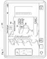
- FIGS. 2-12illustrate an example user interface 100 of an embodiment of the clinician programmer 60 .
- the user interface 100is intended for a target user, which may be a healthcare professional, for example a surgeon or a doctor.
- the user and the healthcare professionalare interchangeably referred in the following paragraphs, but it is understood that they need not necessarily be the same entity.
- the user interface 100displays a virtual reality representation of an anatomical environment 110 (also referred to as anatomical surroundings) of a patient.
- the virtual reality representation of the anatomical environment 110may involve 3-D or 2-D models.
- the anatomical environment 110includes a portion of a spine.
- the anatomical environment 110may include other parts of the human body, for example the brain, the heart, or the abdomen, etc.
- the patient's physiological data(for example the patient's height or weight) is obtained by detecting user input through the user interface 100 .
- the patient's physiological datamay be obtained or through another suitable mechanism such as from an electronic database, which can be remote or local to the programmer.
- the virtual reality representation of the anatomical environment 110may be customized in response to the patient's physiological data.
- the spine(or another implementation of the anatomical environment) may be scaled based on the height of the patient.
- the user interface 100 Aalso includes a graphical display 120 that shows an entire human body (simulating the patient's body). A portion of the human body corresponding to the anatomical environment 110 is highlighted by a box superimposed on the human body. The user can quickly access a particular location of the human body by moving the box to that location. As the box is being moved, the anatomical environment 110 is updated to reflect the change.
- the user interface 110also offers a zoom feature 125 that can be used to show a closer view (by zooming in) or a farther view (by zooming out) of the human body in the graphical display 120 .
- the zoom feature 125when the zoom feature 125 is activated to zoom in the human body, a more detailed view (e.g., showing fewer vertebrae) of the anatomical environment 110 is shown. Conversely, when the zoom feature 125 is activated to zoom out of the human body, a less detailed view (e.g., showing more vertebrae) of the anatomical environment 110 is shown.
- the user interface 100further includes a digital carousel 130 that shows the virtual reality representations of a plurality of medical devices.
- the virtual reality representation of each medical devicemay include an accurate movable and individually rotatable 3-D model of the medical device.
- the medical devicesmay be of different types, for example different types of leads, paddles, and pulse generators (including both implantable pulse generators (IPG) and external pulse generators (EPG).) These different types of medical devices are arranged in the carousel 130 , which is spinnable. As the user spins the carousel 130 , for example by moving his finger to the left or right on the touch screen, the models of different medical devices may be brought to the front of the carousel 130 .
- the medical device at the front of the carousel 130may be considered a temporary active selection from the user.
- a paddle of a lead 140(e.g., a 2 ⁇ 6 paddle lead having 12 electrodes) is displayed at the front of the carousel 130 and may be considered an active selection. Additional aspects of the digital carousel 130 are discussed in more detail in U.S. patent application Ser. No. 13/601,449, filed on Aug. 31, 2012, entitled “Virtual Reality Representation of Medical Devices”, the disclosure of which is hereby incorporated by reference in its entirety.
- the paddle of the lead 140may hereinafter be referred to as the lead 140 , but it is understood that the actual lead includes not just the paddle shown in FIG. 2 but also an elongated lead wire (not illustrated).
- the lead 140may be placed (for example by dragging) in a desired location in the virtual reality representation of the anatomical environment 110 (i.e., the spinal cord).
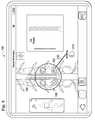
- the usermay trigger the display of an options menu 150 by touching and holding the lead 140 once the lead 140 has been properly positioned on the spinal cord.
- the options menu 150includes a set of icons 160 - 163 each disposed within a circle, but it is understood that the options menu 150 may assume other forms in alternative embodiments.
- the icon 160allows the lead 140 to be locked
- the icon 161allows the lead 140 to be rotated
- the icon 162allows the lead 140 to be deleted
- the icon 153allows a simulated connection to be generated to connect the lead 140 to another medical device.
- the simulated connectionis to be made with a pulse generator, for example an IPG 170 in this case.
- the simulated connectionmay also be made with a lead connector block used in conjunction with an EPG in other embodiments.
- the IPG 170may be selected from the digital carousel 130 .
- To initiate the simulated connection processreferring to FIG. 3 , where the user engages the icon 163 via a simulated cursor 180 . In other words, the user may click or press on the icon 163 , which is illustrated by the simulated cursor 180 being moved over the icon 163 .
- the window 190contains a detailed and realistic illustration of the IPG 170 .
- the IPG 170 in the illustrated embodimentincludes two ports (also referred to as bores) 191 (Port 01 ) and 192 (Port 02 ). The user may then select which of the ports 191 and 192 the connection to the IPG 170 should be made. After the user selects the specific port on the IPG 170 , a simulated connection 200 is automatically generated between the IPG 170 and the lead 140 , as shown in FIG. 5 .
- FIGS. 2-5illustrate a process for connecting the lead 140 with the IPG 170 .
- a similar processmay also be used to establish a simulated connection between the lead 140 and a lead connector block 210 , as shown in FIGS. 6-8 .
- the usermay select the lead connector block 210 from the carousel 130 . Thereafter, the user may trigger the display of the options menu 150 by touching and holding the lead 140 , which has already been properly positioned on the spinal cord.
- the userengages with the icon 163 to trigger the display of a window 220 , which is shown in FIG. 7 .
- the window 220contains a detailed and realistic illustration of the lead connector block 210 .
- the lead connector block 210 in the illustrated embodimentincludes five ports (also referred to as bores) 221 - 225 (Ports 01 - 05 ). However, only ports 222 and 224 (Ports 02 and 04 ) are available here, as they are the two ports compatible with the 12-contact lead 140 .
- the ports 221 - 225 of the lead connector block 210may include a plurality of ports or bores that may each be configured to accommodate (or be connected to) a specific type of lead.
- the present disclosureautomatically detects the type of lead (i.e., the lead 140 ) that is to be connected, and only the ports/bores compatible with that lead will be shown as being available on the lead connector block 210 .
- a simulated connection 230is automatically generated between that selected port and the lead 140 .
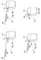
- FIGS. 9A-9Dillustrate an example process of simulating the connection between the lead 140 and the IPG 170 with detail and clarity.
- the lead wire 250is attached to the paddle of the lead 140 illustrated in FIGS. 2-8 .
- the lead wire 250 and the paddle of the lead 140collectively make up the “lead.”
- the paddle of the lead 140is not illustrated in FIGS. 9A-9D , but it is understood that it may optionally be illustrated in other embodiments.
- the lead wire 250includes a plurality of conductive connectors 260 (twelve in this case) that are each electrically coupled to a respective one of the twelve electrode contacts on the paddle.
- the conductive connectors 260are metal rings or metal bands.
- the virtual representation of the IPG 170also includes the ports 191 - 192 .
- the lead wire 250is still at a relatively far distance from the ports 191 - 192 of the IPG 170 .
- the lead wire 250moves closer to the IPG 170 , specifically, to the port 191 of the IPG 170 . This is in response to the user having selected the port 191 to be connected to the lead wire 250 .
- the lead wire 250is successfully connected to the port 191 of the IPG 170 .
- the virtual representation of the lead wire 250is inserted into the port 191 of the IPG 170 , such that every one of the twelve conductive connectors 260 on the lead wire 250 is supposed to make electrical contact with a corresponding electrode inside the port 191 of the IPG 170 .
- the process illustrated in FIGS. 9A-9Dmay be shown as a short animation sequence.
- Such animation sequencemay be integrated into, or shown separately from, the simulated connections process shown in FIGS. 2-8 .
- the animation sequencemay be displayed after the simulated connection 200 is established.
- the simulated connection 200itself may be configured to resemble the lead wire 250 .
- the lead wire 250may be automatically connected to the target port of the IPG 170 in the same manner that the simulated connections 200 is made, or the user may be allowed to move or otherwise manipulate the lead wire 250 to make the connection with the target port of the IPG 170 .
- the user interface 100will provide a recognizable feedback to the user.
- the feedbackmay be audible (e.g., a clicking sound or another suitable sound), tactile (e.g., a haptic response), or visual (e.g., an animated notification or just a highlighting of the target port on the IPG 170 ).
- the useris informed that the simulated connection between the lead wire 250 and the IPG 170 has been successfully established.
- the user interface 100will prevent the lead wire 250 from being inserted into the target port of the IPG until the actual connection is made between the lead wire and the IPG.
- the lead wire 250may be stopped before being inserted into the port 191 , for example it may be suspended in a state depicted in FIG. 9C .
- the user interface 100will be updated to reflect the actual connection being made.
- the lead wire 250may now be automatically inserted into the port 191 (such as shown in FIG. 9D ), and the insertion may be accompanied by an audible sound or notification (e.g., a click) in some embodiments.
- a lead connector blockmay be used in another embodiment instead of the IPG 170 .
- the animation sequence discussed above with reference to FIGS. 9A-9Dmay apply with the lead connector block as well.
- the simulated connections 200 / 230represent the actual connections between a lead and an IPG or a lead connector block.
- the clinician programmermay establish a communications link with the IPG or the lead connector block.
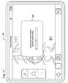
- the user interface 100automatically displays a window 270 .
- the window 270may display a message asking if the user wishes to establish a communications link between the clinician programmer and the pulse generator (e.g., IPG).
- the window 270is automatically triggered after the simulated connection 200 between the lead 140 and the IPG 170 has been made.
- the window 270may be manually invoked before the simulated connection 200 between the lead 140 and the IPG has been made.
- the usermay choose to establish a communications link between the clinician programmer and the IPG or another external medical device before making the simulated connections via the user interface 100 .
- the clinician programmerwill automatically check the connection health between the lead 140 and the IPG 170 (or the lead connector block 210 in embodiments where the lead connector block 210 is connected to the lead 140 ). While the connection health is being checked, a progress bar 280 may be displayed.
- the connection healthis being verified by an impedance test.
- an impedance testFor a high quality connection to exist between the lead 140 and the IPG 170 (or the lead connector block 210 ), each of the twelve connectors on the lead wire should make good contact with the electrodes of the IPG 170 (or the lead connector block 210 ).
- the IPG 170 and the lead connector block 210are implanted inside a human body, fluids or other bodily materials may be pushed into the connection assembly or otherwise degrade the quality of the connections. These conditions are typically associated with an abnormal change in impedance values at the connection locations (i.e., the interface between the connectors on the lead wire and the electrodes of the IPG).
- the IPG 170 (or the lead connector block 210 )can perform impedance tests for each of the twelve connection locations.
- the results of the impedance testmay then be relayed back to the clinician programmer, as shown in FIG. 12 .
- the results from the impedance testare displayed in the form of an impedance check report 290 .
- the impedance check report 290displays the port/bore to which the connection is made with the lead (port 222 in this case).
- the connection status for each of the twelve contactsis also displayed via a visual mechanism 295 , which includes twelve dots of one or more colors. Each of the twelve dots of the visual mechanism 295 corresponds to a respective one of the contacts (or the interface between the conductive connector on the lead wire and the electrode of the IPG).
- the impedance check reportfurther displays the specific problematic connections, which are the connections associated with contact numbers 4 and 7 in this case.
- the specific impedance values detected at these contact numbersmay also be displayed (e.g. 150 ohms and 100 ohms in this case, respectively).
- the problematic contactsi.e., numbers 4 and 7 in this case
- the problematic contactsmay be displayed with a different color than the rest of the contacts in the visual mechanism 295 . For example, while the healthy contacts are displayed in a green color, the problematic contacts 4 and 7 may be displayed in a red color.
- the clinician programmer of the present disclosureis capable of providing graphical simulations for devices that are not currently supported by the programmer. For example, after the clinician programmer has been released and deployed, a new pulse generator, lead, or lead connector block may become available. The clinician programmer does not currently have the information needed to provide graphical representations of these devices since they are new. However, the clinician programmer may download such information via a network (e.g., a cloud network or a remote database), an SD card or another portable memory storage device, or even by direct communication (which may be wireless) with the pulse generator. Regardless of how the clinician programmer retrieves the information associated with providing graphical representations of the pulse generator/lead/lead connector block, the clinician programmer can now provide graphical representations of these devices and the connections therewith in the same manner as discussed above.
- a networke.g., a cloud network or a remote database
- SD cardSecure Digital
- the clinician programmer of the present disclosureoffers various advantages over existing clinician programmers and provides solutions to various problems associated with the lack of visualization of medical devices in the neurostimulation context.
- connections between the lead(s) and the connector blocks or IPGsare not visually displayed, thereby forcing the user (e.g., healthcare professional) to memorize these connections.
- userse.g., healthcare professional
- the clinician programmergraphically represents the lead(s), IPG, the lead connector block, and the connections therebetween in a graphical user interface.
- the usermay readily refer to the user interface for the specific connections instead of relying only on memory.
- the graphical representations and recording of connectionsautomatically tracks leads and their respective connection ports, thereby reducing user errors.
- connection quality informationis not displayed visually.
- clinician programmer hereindisplays connection quality information in a visual representation as well as in a written form (e.g., by text).
- a written forme.g., by text
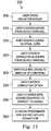
- FIGS. 13-15are simplified flowcharts illustrating the process and methods performed to carry out the various aspects of the present disclosure. It is understood that for each of these flowcharts, some of the process steps may only be briefly discussed, the illustrated steps need not necessarily be performed in sequential order as illustrated unless specifically specified, and that additional process steps (not illustrated) may be performed before, during, or after the illustrated process steps.
- FIG. 13is a flowchart illustrating a process 300 of using virtual representations and visual user feedback of connections according to various aspects of the present disclosure.
- the process 300includes a step 305 , in which the user opens an emulation screen on the clinician programmer.
- the process 300continues with a step 310 , in which the user chooses lead(s) from a virtual device carousel.
- the process 300continues with a step 315 , in which the user adjusts the lead(s) on a virtual representation of a spinal cord.
- the process 300continues with a step 320 , in which the user chooses a connector block or an IPG from the virtual device carousel.
- the process 300continues with a step 325 , in which the user touches the virtual representation of the lead(s) to bring up the display of an option menu.
- the process 300continues with a step 330 , in which the user chooses the connection option.
- the process 300continues with a step 335 , in which the user chooses the bore (connection port) on the IPG or the connector block to connect to the lead(s).
- the process 300continues with a step 340 , in which the clinician programmer application displays the simulated connections between the lead(s) and the IPG or the connector block.
- FIG. 14is a simplified flowchart illustrating a method 350 of showing connections quality between a lead and a pulse generator or a lead connector block according to various aspects of the present disclosure.
- the method 350includes a step 355 , in which the clinician programmer establishes wireless communication with an IPG/EPG.
- the method 350continues with a step 360 , in which the IPG tests the impedance of the lead-IPG connection, or the EPG tests the impedance of the lead-connector block connection.
- the method 350continues with a step 365 , in which the IPG/EPG reports the connection quality to the clinician programmer.
- the method 350continues with a step 370 , in which the clinician programmer application displays the connection quality information in a visual representation and in a list.
- FIG. 15is a simplified flowchart illustrating a method 500 of providing graphical representations of medical devices and connections between the medical devices.
- the methodincludes a step 510 of displaying, via a touch-sensitive graphical user interface of a portable electronic device, a graphical representation of a lead.
- the leadis configured to deliver electrical stimulation to a patient via one or more of a plurality of electrode contacts located on the lead.
- the portable electronic deviceincludes a clinician programmer or a tablet computer.
- the methodincludes a step 520 of displaying, via the graphical user interface, a graphical representation of one of: an implantable pulse generator (IPG) or a lead connector block.
- IPGimplantable pulse generator
- the IPG and the lead connector blockare each configured for coupling with the lead.
- the methodincludes a step 530 of generating, in response to a user input, a graphical representation of a connection between the lead and one of: the IPG or the lead connector block.
- the methodincludes a step 540 of establishing a communications link between the portable electronic device and one of: the IPG or the lead connector block.
- the methodincludes a step 550 of monitoring an actual connection between the lead and one of: the IPG or the lead connector block.
- the methodincludes a step 560 of reporting a status of the actual connection between the lead and one of: the IPG or the connector block.
- the step 520 of displaying the graphical representation of the leadcomprises displaying the graphical representation of the lead over a graphical representation of a human spinal cord.
- the step 530comprises: indicating, for the IPG or the lead connector block, a plurality of ports available for connection with the lead; prompting the user to select one of the available ports for connection with the lead; and establishing the graphical representation of the connection between the selected port and the lead.
- the step 530comprises displaying an animation sequence that shows a graphical representation of a lead wire of the lead being inserted into a port of one of: the IPG or the lead connector block.
- the step of displaying the animation sequencecomprises preventing the graphical representation of the lead wire from being inserted into the port until after the actual connection is made between the lead and the one of: the IPG or the lead connector block.
- the method 500further comprises a step of providing a feedback to the user when the graphical representation of the lead wire has been successfully inserted into the port.
- the feedbackis one of: an audible feedback, a visual feedback, and a tactile feedback.
- the step 550comprises performing an impedance check for each of the electrode contacts on the lead.
- the step 560comprises visually indicating electrode contacts that are problematic.
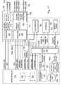
- FIG. 16shows a block diagram of one embodiment of the electronic programmer discussed herein.
- the electronic programmermay be a clinician programmer (CP) configured to provide the graphical representations of medical devices and connections between the medical devices as discussed above. It is understood, however, that alternative embodiments of the electronic programmer may be used to perform these representations as well.
- CPclinician programmer
- the CPincludes a printed circuit board (“PCB”) that is populated with a plurality of electrical and electronic components that provide power, operational control, and protection to the CP.
- the CPincludes a processor 600 .
- the processor 600controls the CP.
- the processor 600is an applications processor model i.MX515 available from Free scale Semiconductor®. More specifically, the i.MX515 applications processor has internal instruction and data caches, multimedia capabilities, external memory interfacing, and interfacing flexibility. Further information regarding the i.MX515 applications processor can be found in, for example, the “IMX51CEC, Rev. 4” data sheet dated August 2010 and published by Free scale Semiconductor® at www.freescale.com. The content of the data sheet is incorporated herein by reference. Of course, other processing units, such as other microprocessors, microcontrollers, digital signal processors, etc., can be used in place of the processor 600 .
- the CPincludes memory, which can be internal to the processor 600 (e.g., memory 605 ), external to the processor 600 (e.g., memory 610 ), or a combination of both.
- Exemplary memoryinclude a read-only memory (“ROM”), a random access memory (“RAM”), an electrically erasable programmable read-only memory (“EEPROM”), a flash memory, a hard disk, or another suitable magnetic, optical, physical, or electronic memory device.
- the processor 600executes software that is capable of being stored in the RAM (e.g., during execution), the ROM (e.g., on a generally permanent basis), or another non-transitory computer readable medium such as another memory or a disc.
- the CPalso includes input/output (“I/O”) systems that include routines for transferring information between components within the processor 600 and other components of the CP or external to the CP.
- I/Oinput/output
- the software included in the implementation of the CPis stored in the memory 605 of the processor 600 , RAM 610 , ROM 615 , or external to the CP.
- the softwareincludes, for example, firmware, one or more applications, program data, one or more program modules, and other executable instructions.
- the processor 600is configured to retrieve from memory and execute, among other things, instructions related to the control processes and methods described below for the CP.
- memory 610which may be a double data rate (DDR2) synchronous dynamic random access memory (SDRAM) for storing data relating to and captured during the operation of the CP.
- DDR2double data rate
- SDRAMsynchronous dynamic random access memory
- MMCsecure digital multimedia card
- other types of data storage devicesmay be used in place of the data storage devices shown in FIG. 16 .
- the CPincludes multiple bi-directional radio communication capabilities. Specific wireless portions included with the CP are a Medical Implant Communication Service (MICS) bi-directional radio communication portion 620 , a Wi-Fi bi-directional radio communication portion 625 , and a Bluetooth bi-directional radio communication portion 630 .
- the MICS portion 620includes a MICS communication interface, an antenna switch, and a related antenna, all of which allows wireless communication using the MICS specification.
- the Wi-Fi portion 625 and Bluetooth portion 630include a Wi-Fi communication interface, a Bluetooth communication interface, an antenna switch, and a related antenna all of which allows wireless communication following the Wi-Fi Alliance standard and Bluetooth Special Interest Group standard. Of course, other wireless local area network (WLAN) standards and wireless personal area networks (WPAN) standards can be used with the CP.
- WLANwireless local area network
- WPANwireless personal area networks
- the CPincludes three hard buttons: a “home” button 635 for returning the CP to a home screen for the device, a “quick off” button 640 for quickly deactivating stimulation IPG, and a “reset” button 645 for rebooting the CP.
- the CPalso includes an “ON/OFF” switch 650 , which is part of the power generation and management block (discussed below).
- the CPincludes multiple communication portions for wired communication.
- Exemplary circuitry and ports for receiving a wired connectorinclude a portion and related port for supporting universal serial bus (USB) connectivity 655 , including a Type A port and a Micro-B port; a portion and related port for supporting Joint Test Action Group (JTAG) connectivity 660 , and a portion and related port for supporting universal asynchronous receiver/transmitter (UART) connectivity 665 .
- USBuniversal serial bus
- JTAGJoint Test Action Group
- UARTuniversal asynchronous receiver/transmitter
- HDMIHigh-Definition Multimedia Interface
- the use of the HDMI connection 670allows the CP to transmit video (and audio) communication to an external display. This may be beneficial in situations where others (e.g., the surgeon) may want to view the information being viewed by the healthcare professional. The surgeon typically has no visual access to the CP in the operating room unless an external screen is provided.
- the HDMI connection 670allows the surgeon to view information from the CP, thereby allowing greater communication between the clinician and the surgeon.
- the HDMI connection 670can broadcast a high definition television signal that allows the surgeon to view the same information that is shown on the LCD (discussed below) of the CP.
- the CPincludes a touch screen I/O device 675 for providing a user interface with the clinician.
- the touch screen display 675can be a liquid crystal display (LCD) having a resistive, capacitive, or similar touch-screen technology. It is envisioned that multitouch capabilities can be used with the touch screen display 675 depending on the type of technology used.
- LCDliquid crystal display
- the CPincludes a camera 680 allowing the device to take pictures or video.
- the resulting image filescan be used to document a procedure or an aspect of the procedure.
- Other devicescan be coupled to the CP to provide further information, such as scanners or RFID detection.
- the CPincludes an audio portion 685 having an audio codec circuit, audio power amplifier, and related speaker for providing audio communication to the user, such as the clinician or the surgeon.
- the CPfurther includes a power generation and management block 690 .
- the power block 690has a power source (e.g., a lithium-ion battery) and a power supply for providing multiple power voltages to the processor, LCD touch screen, and peripherals.
- a power sourcee.g., a lithium-ion battery
- a power supplyfor providing multiple power voltages to the processor, LCD touch screen, and peripherals.
- the CPis a handheld computing tablet with touch screen capabilities.
- the tabletis a portable personal computer with a touch screen, which is typically the primary input device. However, an external keyboard or mouse can be attached to the CP.
- the tabletallows for mobile functionality not associated with even typical laptop personal computers.
- the hardwaremay include a Graphical Processing Unit (GPU) in order to speed up the user experience.
- An Ethernet port(not shown in FIG. 16 ) may also be included for data transfer.
- a patient programmermay be implemented in a similar manner as the clinician programmer shown in FIG. 16 .
- FIG. 17shows a block diagram of one embodiment of an implantable medical device.
- the implantable medical deviceincludes an implantable pulse generator (IPG).
- the IPGincludes a printed circuit board (“PCB”) that is populated with a plurality of electrical and electronic components that provide power, operational control, and protection to the IPG.
- the IPGincludes a communication portion 700 having a transceiver 705 , a matching network 710 , and antenna 712 .
- the communication portion 700receives power from a power ASIC (discussed below), and communicates information to/from the microcontroller 715 and a device (e.g., the CP) external to the IPG.
- the IPGcan provide bi-direction radio communication capabilities, including Medical Implant Communication Service (MICS) bi-direction radio communication following the MICS specification.
- MICSMedical Implant Communication Service
- the IPGprovides stimuli to electrodes of an implanted medical electrical lead (not illustrated herein). As shown in FIG. 17 , N electrodes are connected to the IPG. In addition, the enclosure or housing 720 of the IPG can act as an electrode. The stimuli are provided by a stimulation portion 225 in response to commands from the microcontroller 215 .
- the stimulation portion 725includes a stimulation application specific integrated circuit (ASIC) 730 and circuitry including blocking capacitors and an over-voltage protection circuit.
- ASICapplication specific integrated circuit
- an ASICis an integrated circuit customized for a particular use, rather than for general purpose use. ASICs often include processors, memory blocks including ROM, RAM, EEPROM, FLASH, etc.
- the stimulation ASIC 730can include a processor, memory, and firmware for storing preset pulses and protocols that can be selected via the microcontroller 715 .
- the providing of the pulses to the electrodesis controlled through the use of a waveform generator and amplitude multiplier of the stimulation ASIC 730 , and the blocking capacitors and overvoltage protection circuitry 735 of the stimulation portion 725 , as is known in the art.
- the stimulation portion 725 of the IPGreceives power from the power ASIC (discussed below).
- the stimulation ASIC 730also provides signals to the microcontroller 715 . More specifically, the stimulation ASIC 730 can provide impedance values for the channels associated with the electrodes, and also communicate calibration information with the microcontroller 715 during calibration of the IPG.
- the IPGalso includes a power supply portion 740 .
- the power supply portionincludes a rechargeable battery 745 , fuse 750 , power ASIC 755 , recharge coil 760 , rectifier 763 and data modulation circuit 765 .
- the rechargeable battery 745provides a power source for the power supply portion 740 .
- the recharge coil 760receives a wireless signal from the PPC.
- the wireless signalincludes an energy that is converted and conditioned to a power signal by the rectifier 763 .
- the power signalis provided to the rechargeable battery 745 via the power ASIC 755 .
- the power ASIC 755manages the power for the IPG.
- the power ASIC 755provides one or more voltages to the other electrical and electronic circuits of the IPG.
- the data modulation circuit 765controls the charging process.
- the IPGalso includes a magnetic sensor 780 .
- the magnetic sensor 780provides a “hard” switch upon sensing a magnet for a defined period.
- the signal from the magnetic sensor 780can provide an override for the IPG if a fault is occurring with the IPG and is not responding to other controllers.
- the IPGis shown in FIG. 17 as having a microcontroller 715 .
- the microcontroller 715is a controller for controlling the IPG.
- the microcontroller 715includes a suitable programmable portion 785 (e.g., a microprocessor or a digital signal processor), a memory 790 , and a bus or other communication lines.
- An exemplary microcontroller capable of being used with the IPGis a model MSP430 ultra-low power, mixed signal processor by Texas Instruments. More specifically, the MSP430 mixed signal processor has internal RAM and flash memories, an internal clock, and peripheral interface capabilities.
- MSP430G2x32, MSP430G2x02 MIXED SIGNAL MICROCONTROLLER” data sheetdated December 2010, published by Texas Instruments at www.ti.com; the content of the data sheet being incorporated herein by reference.
- the IPGincludes memory, which can be internal to the control device (such as memory 790 ), external to the control device (such as serial memory 795 ), or a combination of both.
- Exemplary memoryinclude a read-only memory (“ROM”), a random access memory (“RAM”), an electrically erasable programmable read-only memory (“EEPROM”), a flash memory, a hard disk, or another suitable magnetic, optical, physical, or electronic memory device.
- the programmable portion 785executes software that is capable of being stored in the RAM (e.g., during execution), the ROM (e.g., on a generally permanent basis), or another non-transitory computer readable medium such as another memory or a disc.
- the software included in the implementation of the IPGis stored in the memory 790 .
- the softwareincludes, for example, firmware, one or more applications, program data, one or more program modules, and other executable instructions.
- the programmable portion 785is configured to retrieve from memory and execute, among other things, instructions related to the control processes and methods described below for the IPG.
- the programmable portion 285is configured to execute instructions retrieved from the memory 790 for sweeping the electrodes in response to a signal from the CP.
- the medical infrastructure 800includes a plurality of medical devices 810 .
- These medical devices 810may each be a programmable medical device (or parts thereof) that can deliver a medical therapy to a patient.
- the medical devices 810may include a device of the neurostimulator system discussed above with reference to FIG. 1 .
- the medical devices 810may be a pulse generator (e.g., the IPG discussed above with reference to FIG. 17 ), an implantable lead, a charger, or portions thereof. It is understood that each of the medical devices 810 may be a different type of medical device. In other words, the medical devices 810 need not be the same type of medical device.
- the medical infrastructure 800also includes a plurality of electronic programmers 820 .
- a plurality of electronic programmers 820For sake of illustration, one of these electronic programmers 820 A is illustrated in more detail and discussed in detail below. Nevertheless, it is understood that each of the electronic programmers 820 may be implemented similar to the electronic programmer 820 A.
- the electronic programmer 820 Amay be a clinician programmer, for example the clinician programmer discussed above with reference to FIG. 16 . In other embodiments, the electronic programmer 820 A may be a patient programmer or another similar programmer. In further embodiments, it is understood that the electronic programmer may be a tablet computer. In any case, the electronic programmer 820 A is configured to program the stimulation parameters of the medical devices 810 so that a desired medical therapy can be delivered to a patient.
- the electronic programmer 820 Acontains a communications component 830 that is configured to conduct electronic communications with external devices.
- the communications device 830may include a transceiver.
- the transceivercontains various electronic circuitry components configured to conduct telecommunications with one or more external devices.
- the electronic circuitry componentsallow the transceiver to conduct telecommunications in one or more of the wired or wireless telecommunications protocols, including communications protocols such as IEEE 802.11 (Wi-Fi), IEEE 802.15 (Bluetooth), GSM, CDMA, LTE, WIMAX, DLNA, HDMI, Medical Implant Communication Service (MICS), etc.
- the transceiverincludes antennas, filters, switches, various kinds of amplifiers such as low-noise amplifiers or power amplifiers, digital-to-analog (DAC) converters, analog-to-digital (ADC) converters, mixers, multiplexers and demultiplexers, oscillators, and/or phase-locked loops (PLLs).
- DACdigital-to-analog
- ADCanalog-to-digital
- PLLsphase-locked loops
- Some of these electronic circuitry componentsmay be integrated into a single discrete device or an integrated circuit (IC) chip.
- the electronic programmer 820 Acontains a touchscreen component 840 .
- the touchscreen component 840may display a touch-sensitive graphical user interface that is responsive to gesture-based user interactions.
- the touch-sensitive graphical user interfacemay detect a touch or a movement of a user's finger(s) on the touchscreen and interpret these user actions accordingly to perform appropriate tasks.
- the graphical user interfacemay also utilize a virtual keyboard to receive user input.
- the touch-sensitive screenmay be a capacitive touchscreen. In other embodiments, the touch-sensitive screen may be a resistive touchscreen.
- the electronic programmer 820 Amay optionally include additional user input/output components that work in conjunction with the touchscreen component 840 to carry out communications with a user.
- these additional user input/output componentsmay include physical and/or virtual buttons (such as power and volume buttons) on or off the touch-sensitive screen, physical and/or virtual keyboards, mouse, track balls, speakers, microphones, light-sensors, light-emitting diodes (LEDs), communications ports (such as USB or HDMI ports), joy-sticks, etc.
- the electronic programmer 820 Acontains an imaging component 850 .
- the imaging component 850is configured to capture an image of a target device via a scan.
- the imaging component 850may be a camera in some embodiments.
- the cameramay be integrated into the electronic programmer 820 A.
- the cameracan be used to take a picture of a medical device, or scan a visual code of the medical device, for example its barcode or Quick Response (QR) code.
- QRQuick Response
- the electronic programmercontains a memory storage component 860 .
- the memory storage component 860may include system memory, (e.g., RAM), static storage 608 (e.g., ROM), or a disk drive (e.g., magnetic or optical), or any other suitable types of computer readable storage media.
- system memorye.g., RAM
- static storage 608e.g., ROM
- disk drivee.g., magnetic or optical
- some common types of computer readable mediamay include floppy disk, flexible disk, hard disk, magnetic tape, any other magnetic medium, CD-ROM, any other optical medium, RAM, PROM, EPROM, FLASH-EPROM, any other memory chip or cartridge, or any other medium from which a computer is adapted to read.
- the computer readable mediummay include, but is not limited to, non-volatile media and volatile media.
- the computer readable mediumis tangible, concrete, and non-transitory.
- Logicfor example in the form of computer software code or computer instructions may be encoded in such computer readable medium.
- the memory storage component 860(or a portion thereof) may be configured as a local database capable of storing electronic records of medical devices and/or their associated patients.
- the electronic programmercontains a processor component 870 .
- the processor component 870may include a central processing unit (CPU), a graphics processing unit (GPU) a micro-controller, a digital signal processor (DSP), or another suitable electronic processor capable of handling and executing instructions.
- the processor component 870may be implemented using various digital circuit blocks (including logic gates such as AND, OR, NAND, NOR, XOR gates, etc.) along with certain software code.
- the processor component 870may execute one or more sequences computer instructions contained in the memory storage component 860 to perform certain tasks.
- the electronic programmer 820 Ais not necessarily limited to the components 830 - 870 discussed above, but it may further include additional components that are used to carry out the programming tasks. These additional components are not discussed herein for reasons of simplicity. It is also understood that the medical infrastructure 800 may include a plurality of electronic programmers similar to the electronic programmer 820 A discussed herein, but they are not illustrated in FIG. 18 for reasons of simplicity.
- the medical infrastructure 800also includes an institutional computer system 890 .
- the institutional computer system 890is coupled to the electronic programmer 820 A.
- the institutional computer system 890is a computer system of a healthcare institution, for example a hospital.
- the institutional computer system 890may include one or more computer servers and/or client terminals that may each include the necessary computer hardware and software for conducting electronic communications and performing programmed tasks.
- the institutional computer system 890may include communications devices (e.g., transceivers), user input/output devices, memory storage devices, and computer processor devices that may share similar properties with the various components 830 - 870 of the electronic programmer 820 A discussed above.
- the institutional computer system 890may include computer servers that are capable of electronically communicating with the electronic programmer 820 A through the MICS protocol or another suitable networking protocol.
- the medical infrastructure 800includes a database 900 .
- the database 900is a remote database—that is, located remotely to the institutional computer system 890 and/or the electronic programmer 820 A.
- the database 900is electronically or communicatively (for example through the Internet) coupled to the institutional computer system 890 and/or the electronic programmer.
- the database 900 , the institutional computer system 890 , and the electronic programmer 820 Aare parts of a cloud-based architecture.
- the database 900may include cloud-based resources such as mass storage computer servers with adequate memory resources to handle requests from a variety of clients.
- the institutional computer system 890 and the electronic programmer 820 A(or their respective users) may both be considered clients of the database 900 .
- the functionality between the cloud-based resources and its clientsmay be divided up in any appropriate manner.
- the electronic programmer 820 Amay perform basic input/output interactions with a user, but a majority of the processing and caching may be performed by the cloud-based resources in the database 900 .
- other divisions of responsibilityare also possible in various embodiments.
- sensation mapselectronic data, such as pain and stimulation maps (collectively referred to as sensation maps) may be uploaded from the electronic programmer 820 A to the database 900 .
- the sensation mapsare discussed in more detail in provisional U.S. Patent Application No. 61/695,407, filed on Aug. 31, 2012, entitled “Method and System of Producing 2D Representations of 3D Pain and Stimulation Maps and Implant Models on a Clinician Programmer,” and provisional U.S. Patent Application No. 61/695,721, filed on Aug. 31, 2012, entitled “Method and System of Creating, Displaying, and Comparing Pain and Stimulation Maps,” and provisional U.S. Patent Application No. 61/695,676, filed on Aug. 31, 2012, entitled “Method and System of Adjusting 3D Models of Patients on a Clinician Programmer,” the disclosure of each of which is hereby incorporated by reference in its entirety.
- the sensation maps saved in the database 900may thereafter be downloaded by any of the other electronic programmers 820 B- 820 N communicatively coupled to it, assuming the user of these programmers has the right login permissions.
- That 2D sensation mapcan then be downloaded by the electronic programmer 820 B, which can use the downloaded 2D sensation map to reconstruct or recreate a 3D sensation map.
- a less data-intensive 2D sensation mapmay be derived from a data-heavy 3D sensation map, sent to a different programmer through the database, and then be used to reconstruct the 3D sensation map.
- the sensation mapsare used herein merely as an example to illustrate the transfer of electronic data in the medical infrastructure 800 . Other types of electronic data may also be transferred in a similar (or different) manner.
- the database 900may also include a manufacturer's database in some embodiments. It may be configured to manage an electronic medical device inventory, monitor manufacturing of medical devices, control shipping of medical devices, and communicate with existing or potential buyers (such as a healthcare institution). For example, communication with the buyer may include buying and usage history of medical devices and creation of purchase orders. A message can be automatically generated when a client (for example a hospital) is projected to run out of equipment, based on the medical device usage trend analysis done by the database. According to various aspects of the present disclosure, the database 900 is able to provide these functionalities at least in part via communication with the electronic programmer 820 A and in response to the data sent by the electronic programmer 820 A. These functionalities of the database 900 and its communications with the electronic programmer 820 A will be discussed in greater detail later.
- the medical infrastructure 800further includes a manufacturer computer system 910 .
- the manufacturer computer system 910is also electronically or communicatively (for example through the Internet) coupled to the database 900 .
- the manufacturer computer system 910may also be considered a part of the cloud architecture.
- the computer system 910is a computer system of medical device manufacturer, for example a manufacturer of the medical devices 810 and/or the electronic programmer 820 A.
- the manufacturer computer system 910may include one or more computer servers and/or client terminals that each includes the necessary computer hardware and software for conducting electronic communications and performing programmed tasks.
- the manufacturer computer system 910may include communications devices (e.g., transceivers), user input/output devices, memory storage devices, and computer processor devices that may share similar properties with the various components 830 - 870 of the electronic programmer 820 A discussed above. Since both the manufacturer computer system 910 and the electronic programmer 820 A are coupled to the database 900 , the manufacturer computer system 910 and the electronic programmer 820 A can conduct electronic communication with each other.
- FIG. 19Ais a side view of a spine 1000
- FIG. 19Bis a posterior view of the spine 1000
- the spine 1000includes a cervical region 1010 , a thoracic region 1020 , a lumbar region 1030 , and a sacrococcygeal region 1040 .
- the cervical region 1010includes the top 7 vertebrae, which may be designated with C1-C7.
- the thoracic region 1020includes the next 12 vertebrae below the cervical region 1010 , which may be designated with T1-T12.
- the lumbar region 1030includes the final 5 “true” vertebrae, which may be designated with L1-L5.
- the sacrococcygeal region 1040includes 9 fused vertebrae that make up the sacrum and the coccyx. The fused vertebrae of the sacrum may be designated with S1-S5.
- Neural tissuebranch off from the spinal cord through spaces between the vertebrae.
- the neural tissuecan be individually and selectively stimulated in accordance with various aspects of the present disclosure.
- an IPG device 1100is implanted inside the body.
- the IPG device 1100may include a neurostimulator device.
- a conductive lead 1110is electrically coupled to the circuitry inside the IPG device 1100 .
- the conductive lead 1110may be removably coupled to the IPG device 1100 through a connector, for example.
- a distal end of the conductive lead 1110is attached to one or more electrodes 1120 .
- the electrodes 1120are implanted adjacent to a desired nerve tissue in the thoracic region 1020 .
- the distal end of the lead 1110 with its accompanying electrodesmay be positioned along or near the epidural space of the spinal cord. It is understood that although only one conductive lead 1110 is shown herein for the sake of simplicity, more than one conductive lead 1110 and corresponding electrodes 1120 may be implanted and connected to the IPG device 1100 .
- the electrodes 1120deliver current drawn from the current sources in the IPG device 1100 , therefore generating an electric field near the neural tissue.
- the electric fieldstimulates the neural tissue to accomplish its intended functions.
- the neural stimulationmay alleviate pain in an embodiment.
- a stimulatormay be placed in different locations throughout the body and may be programmed to address a variety of problems, including for example but without limitation; prevention or reduction of epileptic seizures, weight control or regulation of heart beats.
- the IPG device 1100 , the lead 1110 , and the electrodes 1120may be implanted completely inside the body, may be positioned completely outside the body or may have only one or more components implanted within the body while other components remain outside the body. When they are implanted inside the body, the implant location may be adjusted (e.g., anywhere along the spine 1000 ) to deliver the intended therapeutic effects of spinal cord electrical stimulation in a desired region of the spine. Furthermore, it is understood that the IPG device 1100 may be controlled by a patient programmer or a clinician programmer 1200 , the implementation of which may be similar to the clinician programmer shown in FIG. 16 .
Landscapes
- Engineering & Computer Science (AREA)
- Health & Medical Sciences (AREA)
- General Health & Medical Sciences (AREA)
- Physics & Mathematics (AREA)
- General Physics & Mathematics (AREA)
- Human Computer Interaction (AREA)
- Biomedical Technology (AREA)
- Veterinary Medicine (AREA)
- Public Health (AREA)
- Animal Behavior & Ethology (AREA)
- Life Sciences & Earth Sciences (AREA)
- Radiology & Medical Imaging (AREA)
- Nuclear Medicine, Radiotherapy & Molecular Imaging (AREA)
- Mathematical Optimization (AREA)
- Mathematical Physics (AREA)
- Educational Administration (AREA)
- Educational Technology (AREA)
- Theoretical Computer Science (AREA)
- Chemical & Material Sciences (AREA)
- Pure & Applied Mathematics (AREA)
- Business, Economics & Management (AREA)
- Medicinal Chemistry (AREA)
- Mathematical Analysis (AREA)
- Medical Informatics (AREA)
- Computational Mathematics (AREA)
- Algebra (AREA)
- Electrotherapy Devices (AREA)
Abstract
Description
- The connections between the lead(s) and the connector blocks or pulse generators are not displayed.
- Information about connection quality (i.e., whether the electrical pulses are being transmitted fully) is not displayed visually.
- There is no way to tell when a lead is being connected incorrectly.
- Manual connection errors are not detectable.
Consequently, users (e.g., healthcare professionals) must mentally associate the implanted leads and the connection ports the leads are connected to.
Claims (36)
Priority Applications (1)
| Application Number | Priority Date | Filing Date | Title |
|---|---|---|---|
| US14/015,032US8761897B2 (en) | 2012-08-31 | 2013-08-30 | Method and system of graphical representation of lead connector block and implantable pulse generators on a clinician programmer |
Applications Claiming Priority (3)
| Application Number | Priority Date | Filing Date | Title |
|---|---|---|---|
| US201261695420P | 2012-08-31 | 2012-08-31 | |
| US13/601,449US9594877B2 (en) | 2012-08-31 | 2012-08-31 | Virtual reality representation of medical devices |
| US14/015,032US8761897B2 (en) | 2012-08-31 | 2013-08-30 | Method and system of graphical representation of lead connector block and implantable pulse generators on a clinician programmer |
Related Parent Applications (1)
| Application Number | Title | Priority Date | Filing Date |
|---|---|---|---|
| US13/601,449Continuation-In-PartUS9594877B2 (en) | 2012-08-31 | 2012-08-31 | Virtual reality representation of medical devices |
Publications (2)
| Publication Number | Publication Date |
|---|---|
| US20140067020A1 US20140067020A1 (en) | 2014-03-06 |
| US8761897B2true US8761897B2 (en) | 2014-06-24 |
Family
ID=50188530
Family Applications (1)
| Application Number | Title | Priority Date | Filing Date |
|---|---|---|---|
| US14/015,032ActiveUS8761897B2 (en) | 2012-08-31 | 2013-08-30 | Method and system of graphical representation of lead connector block and implantable pulse generators on a clinician programmer |
Country Status (1)
| Country | Link |
|---|---|
| US (1) | US8761897B2 (en) |
Cited By (38)
| Publication number | Priority date | Publication date | Assignee | Title |
|---|---|---|---|---|
| US9308378B2 (en) | 2013-05-03 | 2016-04-12 | Alfred E. Mann Foundation For Scientific Research | Implant recharger handshaking system and method |
| US9427574B2 (en) | 2014-08-15 | 2016-08-30 | Axonics Modulation Technologies, Inc. | Implantable lead affixation structure for nerve stimulation to alleviate bladder dysfunction and other indication |
| US9433779B2 (en) | 2013-05-03 | 2016-09-06 | Alfred E. Mann Foundation For Scientific Research | Multi-branch stimulation electrode for subcutaneous field stimulation |
| US9446241B2 (en) | 2013-03-15 | 2016-09-20 | Alfred E. Mann Foundation For Scientific Research | Current sensing multiple output current stimulators |
| US9517338B1 (en) | 2016-01-19 | 2016-12-13 | Axonics Modulation Technologies, Inc. | Multichannel clip device and methods of use |
| US9533155B2 (en) | 2014-08-15 | 2017-01-03 | Axonics Modulation Technologies, Inc. | Methods for determining neurostimulation electrode configurations based on neural localization |
| US9555246B2 (en) | 2014-08-15 | 2017-01-31 | Axonics Modulation Technologies, Inc. | Electromyographic lead positioning and stimulation titration in a nerve stimulation system for treatment of overactive bladder |
| US9669227B2 (en) | 2015-06-09 | 2017-06-06 | Nuvectra Corporation | Systems, methods, and devices for generating arbitrary stimulation waveforms |
| US9675807B2 (en) | 2013-05-03 | 2017-06-13 | Alfred E. Mann Foundation For Scientific Research | High reliability wire welding for implantable devices |
| US9682237B2 (en) | 2013-03-15 | 2017-06-20 | Alfred E. Mann Foundation For Scientific Research | High voltage monitoring successive approximation analog to digital converter |
| US9700731B2 (en) | 2014-08-15 | 2017-07-11 | Axonics Modulation Technologies, Inc. | Antenna and methods of use for an implantable nerve stimulator |
| US9728981B2 (en) | 2012-08-31 | 2017-08-08 | Alfred E. Mann Foundation For Scientific Research | Feedback controlled coil driver for inductive power transfer |
| US9750946B2 (en) | 2015-06-09 | 2017-09-05 | Nuvectra Corporation | Systems, methods, and devices for evaluating lead placement based on generated visual representations of sacrum and lead |
| US9780596B2 (en) | 2013-07-29 | 2017-10-03 | Alfred E. Mann Foundation For Scientific Research | Microprocessor controlled class E driver |
| US9802051B2 (en) | 2014-08-15 | 2017-10-31 | Axonics Modulation Technologies, Inc. | External pulse generator device and associated methods for trial nerve stimulation |
| US9855436B2 (en) | 2013-07-29 | 2018-01-02 | Alfred E. Mann Foundation For Scientific Research | High efficiency magnetic link for implantable devices |
| US9872988B2 (en) | 2015-06-09 | 2018-01-23 | Nuvectra Corporation | Systems, methods, and devices for evaluating lead placement based on patient physiological responses |
| US9895546B2 (en) | 2015-01-09 | 2018-02-20 | Axonics Modulation Technologies, Inc. | Patient remote and associated methods of use with a nerve stimulation system |
| US9925381B2 (en) | 2015-07-10 | 2018-03-27 | Axonics Modulation Technologies, Inc. | Implantable nerve stimulator having internal electronics without ASIC and methods of use |
| US10052490B2 (en) | 2015-06-09 | 2018-08-21 | Nuvectra Corporation | Systems, methods, and devices for performing electronically controlled test stimulation |
| US10076667B2 (en) | 2015-06-09 | 2018-09-18 | Nuvectra Corporation | System and method of performing computer assisted stimulation programming (CASP) with a non-zero starting value customized to a patient |
| US10092762B2 (en) | 2014-08-15 | 2018-10-09 | Axonics Modulation Technologies, Inc. | Integrated electromyographic clinician programmer for use with an implantable neurostimulator |
| US10195423B2 (en) | 2016-01-19 | 2019-02-05 | Axonics Modulation Technologies, Inc. | Multichannel clip device and methods of use |
| US10376704B2 (en) | 2016-02-12 | 2019-08-13 | Axonics Modulation Technologies, Inc. | External pulse generator device and associated methods for trial nerve stimulation |
| US10561835B2 (en) | 2006-10-31 | 2020-02-18 | Medtronic, Inc. | Implantable medical lead with threaded fixation |
| US10603500B2 (en) | 2016-01-29 | 2020-03-31 | Axonics Modulation Technologies, Inc. | Methods and systems for frequency adjustment to optimize charging of implantable neurostimulator |
| US10682521B2 (en) | 2014-08-15 | 2020-06-16 | Axonics Modulation Technologies, Inc. | Attachment devices and associated methods of use with a nerve stimulation charging device |
| US11083887B2 (en) | 2017-09-12 | 2021-08-10 | Boston Scientific Neuromodulation Corporation | Techniques for sensing incorrect lead connection to an implantable stimulator device |
| US11103711B2 (en) | 2017-10-04 | 2021-08-31 | Boston Scientific Neuromodulation Corporation | System and method for ensuring a consistent connection of electrodes to a replacement implantable medical device |
| US11110283B2 (en) | 2018-02-22 | 2021-09-07 | Axonics, Inc. | Neurostimulation leads for trial nerve stimulation and methods of use |
| US11331495B2 (en) | 2018-06-27 | 2022-05-17 | Boston Scientific Neuromodulation Corporation | Stimulation field modelling in an implantable stimulator device |
| US11439829B2 (en) | 2019-05-24 | 2022-09-13 | Axonics, Inc. | Clinician programmer methods and systems for maintaining target operating temperatures |
| US11484723B2 (en) | 2015-01-09 | 2022-11-01 | Axonics, Inc. | Attachment devices and associated methods of use with a nerve stimulation charging device |
| US11571579B2 (en) | 2017-09-12 | 2023-02-07 | Boston Scientific Neuromodulation Corporation | System and method for determination of connected neurostimulation leads |
| US11642537B2 (en) | 2019-03-11 | 2023-05-09 | Axonics, Inc. | Charging device with off-center coil |
| US11738198B2 (en) | 2019-05-10 | 2023-08-29 | The Freestate Of Bavaria Represented By The Julius Maximilians-Universität Würzbrg | System to optimize anodic stimulation modes |
| US11848090B2 (en) | 2019-05-24 | 2023-12-19 | Axonics, Inc. | Trainer for a neurostimulator programmer and associated methods of use with a neurostimulation system |
| US12420103B1 (en) | 2020-08-20 | 2025-09-23 | Axonics, Inc. | Neurostimulation leads with reduced current leakage |
Families Citing this family (5)
| Publication number | Priority date | Publication date | Assignee | Title |
|---|---|---|---|---|
| JP6319748B2 (en)* | 2012-08-29 | 2018-05-09 | ボストン サイエンティフィック ニューロモデュレイション コーポレイション | System and method for connecting a device to a neurostimulator |
| US9931511B2 (en)* | 2013-05-16 | 2018-04-03 | Nuvectra Corporation | Method and apparatus for visualizing a migration history of pain maps and stimulation maps |
| US9539422B2 (en) | 2013-07-02 | 2017-01-10 | Greatbatch Ltd. | Neurostimulator interconnection apparatus, system, and method |
| USD766290S1 (en)* | 2014-08-27 | 2016-09-13 | Janssen Pharmaceutica Nv | Display screen or portion thereof with graphical user interface |
| US10622107B2 (en)* | 2015-02-13 | 2020-04-14 | Medtronic, Inc. | Tools for medical device configuration |
Citations (244)
| Publication number | Priority date | Publication date | Assignee | Title |
|---|---|---|---|---|
| US4432360A (en) | 1981-07-06 | 1984-02-21 | Cordis Corporation | Interactive programmer for biomedical implantable devices |
| US5286202A (en) | 1990-10-30 | 1994-02-15 | Hughes Training, Inc. | Trainer using video photographs and overlays for reconfigurable hardware simulation |
| US5304206A (en) | 1991-11-18 | 1994-04-19 | Cyberonics, Inc. | Activation techniques for implantable medical device |
| US5312446A (en) | 1992-08-26 | 1994-05-17 | Medtronic, Inc. | Compressed storage of data in cardiac pacemakers |
| US5370672A (en) | 1992-10-30 | 1994-12-06 | The Johns Hopkins University | Computer-controlled neurological stimulation system |
| US5383914A (en) | 1992-05-13 | 1995-01-24 | Cardiac Pacemakers, Inc. | Diagnostic connector port for a pulse generator |
| US5421830A (en) | 1993-08-27 | 1995-06-06 | Pacesetter, Inc. | Programming system having means for recording and analyzing a patient's cardiac signal |
| US5628776A (en) | 1995-04-21 | 1997-05-13 | Intermedics, Inc. | Implantable lead with warning system |
| US5713937A (en) | 1995-11-07 | 1998-02-03 | Pacesetter, Inc. | Pacemaker programmer menu with selectable real or simulated implant data graphics |
| US5722999A (en) | 1995-08-02 | 1998-03-03 | Pacesetter, Inc. | System and method for storing and displaying historical medical data measured by an implantable medical device |
| US5724996A (en) | 1996-09-24 | 1998-03-10 | Galaxy-Top International S.P.A. | Method for controlled stimulation of predetermined parts of the human body by application of variable electric signals |
| US5819740A (en) | 1995-11-22 | 1998-10-13 | Medtronic, Inc. | System and method for compressing digitized signals in implantable and battery powered devices |
| US5879374A (en) | 1993-05-18 | 1999-03-09 | Heartstream, Inc. | External defibrillator with automatic self-testing prior to use |
| US5905500A (en) | 1997-02-19 | 1999-05-18 | Seiko Epson Corporation | Method and apparatus for adaptive nonlinear projective rendering |
| US5938690A (en) | 1996-06-07 | 1999-08-17 | Advanced Neuromodulation Systems, Inc. | Pain management system and method |
| US6016448A (en) | 1998-10-27 | 2000-01-18 | Medtronic, Inc. | Multilevel ERI for implantable medical devices |
| US6016447A (en) | 1998-10-27 | 2000-01-18 | Medtronic, Inc. | Pacemaker implant recognition |
| US6052624A (en) | 1999-01-07 | 2000-04-18 | Advanced Bionics Corporation | Directional programming for implantable electrode arrays |
| US6083156A (en) | 1998-11-16 | 2000-07-04 | Ronald S. Lisiecki | Portable integrated physiological monitoring system |
| US6148233A (en) | 1997-03-07 | 2000-11-14 | Cardiac Science, Inc. | Defibrillation system having segmented electrodes |
| US6154675A (en) | 1998-10-27 | 2000-11-28 | Medtronic, Inc. | Resetting ERI/POR/PIR/indicators in implantable medical devices |
| US6216036B1 (en) | 1998-02-17 | 2001-04-10 | Janice M. Jenkins | Implantable cardioverter defibrillator and system for testing same |
| US6246414B1 (en) | 1997-11-17 | 2001-06-12 | Nec Corporation | Image processing in which polygon is divided |
| US6249705B1 (en) | 1999-10-21 | 2001-06-19 | Pacesetter, Inc. | Distributed network system for use with implantable medical devices |
| US6278890B1 (en) | 1998-11-09 | 2001-08-21 | Medacoustics, Inc. | Non-invasive turbulent blood flow imaging system |
| US6308102B1 (en) | 1999-09-29 | 2001-10-23 | Stimsoft, Inc. | Patient interactive neurostimulation system and method |
| US6307554B1 (en) | 1997-12-19 | 2001-10-23 | Fujitsu Limited | Apparatus and method for generating progressive polygon data, and apparatus and method for generating three-dimensional real-time graphics using the same |
| US20010037220A1 (en) | 1999-12-21 | 2001-11-01 | Merry Randy L. | Integrated software system for implantable medical device installation and management |
| US6345200B1 (en) | 2000-02-08 | 2002-02-05 | Pacesetter, Inc. | Implant guiding programmer for implantable cardioverter defibrillator |
| US6386882B1 (en) | 1999-11-10 | 2002-05-14 | Medtronic, Inc. | Remote delivery of software-based training for implantable medical device systems |
| US6442432B2 (en) | 1999-12-21 | 2002-08-27 | Medtronic, Inc. | Instrumentation and software for remote monitoring and programming of implantable medical devices (IMDs) |
| US6525727B1 (en) | 1999-10-29 | 2003-02-25 | Intel Corporation | Rendering 3D surfaces through limit surface projections |
| US20030076301A1 (en) | 2001-10-22 | 2003-04-24 | Apple Computer, Inc. | Method and apparatus for accelerated scrolling |
| US6564104B2 (en) | 1999-12-24 | 2003-05-13 | Medtronic, Inc. | Dynamic bandwidth monitor and adjuster for remote communications with a medical device |
| US20030107572A1 (en) | 2001-07-02 | 2003-06-12 | Smith Joshua Edward | Method and apparatus for reducing the polygon count of a textured, three dimensional model of an object |
| US6587104B1 (en) | 1999-09-30 | 2003-07-01 | Microsoft Corporation | Progressive hulls |
| US20030139652A1 (en) | 2002-01-22 | 2003-07-24 | Ilisoft.Co.Kr | System for pain diagnosis and method therefor |
| US6611267B2 (en) | 1996-10-16 | 2003-08-26 | Viewpoint Corporation | System and method for computer modeling of 3D objects or surfaces by mesh constructions having optimal quality characteristics and dynamic resolution capabilities |
| US20030171911A1 (en) | 2002-02-01 | 2003-09-11 | John Fairweather | System and method for real time interface translation |
| US6622048B1 (en) | 1999-12-06 | 2003-09-16 | Advanced Bionics Corporation | Implantable device programmer |
| US20030177031A1 (en) | 2002-03-15 | 2003-09-18 | Medtronic, Inc. | Data management of patient medical information for use with an implantable medical device |
| US6669631B2 (en) | 2000-06-14 | 2003-12-30 | Medtronic, Inc. | Deep computing applications in medical device systems |
| US20040088374A1 (en) | 2002-10-31 | 2004-05-06 | Webb James D. | Aggregation and sharing of patient data |
| US20040122477A1 (en) | 2002-12-19 | 2004-06-24 | Whitehurst Todd K. | Fully implantable miniature neurostimulator for spinal nerve root stimulation as a therapy for angina and peripheral vascular disease |
| US6786405B2 (en) | 2002-02-28 | 2004-09-07 | Curt Wiedenhoefer | Tissue and implant product supply system and method |
| US20040210273A1 (en) | 2003-04-18 | 2004-10-21 | Medtronic, Inc. | Presentation of patient image with implantable medical device information |
| US6852080B2 (en) | 1999-06-03 | 2005-02-08 | Cardiac Intelligence Corporation | System and method for providing feedback to an individual patient for automated remote patient care |
| US6882982B2 (en) | 2000-02-04 | 2005-04-19 | Medtronic, Inc. | Responsive manufacturing and inventory control |
| US6895280B2 (en) | 1999-07-27 | 2005-05-17 | Advanced Bionics Corporation | Rechargeable spinal cord stimulator system |
| US20050107831A1 (en) | 2003-11-18 | 2005-05-19 | Encore Medical Asset Corporation | System for therapeutic application of energy |
| US20050149356A1 (en) | 2004-01-02 | 2005-07-07 | Cyr Keneth K. | System and method for management of clinical supply operations |
| US6920360B2 (en) | 1999-12-21 | 2005-07-19 | Medtronic, Inc. | Large-scale processing loop for implantable medical devices |
| US20050168460A1 (en) | 2002-04-04 | 2005-08-04 | Anshuman Razdan | Three-dimensional digital library system |
| US6931155B1 (en) | 1998-08-03 | 2005-08-16 | Telediffusion De France | Selective mesh refinement |
| US6961617B1 (en) | 2001-10-19 | 2005-11-01 | Pacesetter, Inc. | Method and apparatus to backup, update and share data among implantable cardiac stimulation device programmers |
| US6961448B2 (en) | 1999-12-30 | 2005-11-01 | Medtronic, Inc. | User authentication in medical device systems |
| US20050277872A1 (en) | 2004-05-24 | 2005-12-15 | Colby John E Jr | Apparatus and method for mobile medical services |
| US7003349B1 (en) | 1999-12-16 | 2006-02-21 | St. Jude Medical Ab | Programming system for medical devices |
| US7034823B2 (en) | 1999-02-04 | 2006-04-25 | Canon Kabushiki Kaisha | 3D computer graphics processing apparatus and method |
| US20060089888A1 (en) | 2004-10-19 | 2006-04-27 | Roger Gregory J | Medical implant distribution method and system |
| US20060100832A1 (en) | 2004-11-08 | 2006-05-11 | Bowman Gerald D | Method a designing, engineering modeling and manufacturing orthotics and prosthetics integrating algorithm generated predictions |
| US7058453B2 (en) | 1999-12-14 | 2006-06-06 | Medtronic, Inc. | Apparatus and method for remote therapy and diagnosis in medical devices via interface systems |
| US7060030B2 (en) | 2002-01-08 | 2006-06-13 | Cardiac Pacemakers, Inc. | Two-hop telemetry interface for medical device |
| EP1192972B1 (en) | 2000-09-28 | 2006-06-14 | BIOTRONIK GmbH & Co. KG | Electrical active implant |
| US7065409B2 (en) | 2002-12-13 | 2006-06-20 | Cardiac Pacemakers, Inc. | Device communications of an implantable medical device and an external system |
| US7066910B2 (en) | 2000-04-27 | 2006-06-27 | Medtronic, Inc. | Patient directed therapy management |
| US7076303B2 (en) | 1999-10-29 | 2006-07-11 | Medtronic, Inc. | Apparatus and method for automated invoicing of medical device systems |
| US7087015B1 (en) | 2000-01-31 | 2006-08-08 | Panmedix, Inc. | Neurological pathology diagnostic apparatus and methods |
| US7092761B1 (en) | 2002-11-06 | 2006-08-15 | Pacesetter, Inc. | Telemetry wand with display and control for implantable medical devices |
| US7107102B2 (en) | 2000-06-05 | 2006-09-12 | Advanced Neuromodulation Systems, Inc. | Neuromodulation therapy system and method |
| US20060241720A1 (en) | 2005-04-26 | 2006-10-26 | Woods Carla M | Graphical representation of pain therapy |
| US20060242159A1 (en) | 2005-03-10 | 2006-10-26 | Bishop Robert J | Methods and apparatus for distributing digital medical images via a redirected system |
| US7142923B2 (en) | 2003-02-21 | 2006-11-28 | Medtronic, Inc. | Implantable neurostimulator programming with battery longevity indication |
| US20060282168A1 (en) | 2005-06-13 | 2006-12-14 | Sherman Jason T | Orthopaedic prosthesis having a superparamagnetic material and associated method |
| US7181286B2 (en) | 2002-10-31 | 2007-02-20 | Medtronic, Inc. | Distributed system for neurostimulation therapy programming |
| US7181505B2 (en) | 1999-07-07 | 2007-02-20 | Medtronic, Inc. | System and method for remote programming of an implantable medical device |
| US7184837B2 (en) | 2003-09-15 | 2007-02-27 | Medtronic, Inc. | Selection of neurostimulator parameter configurations using bayesian networks |
| US20070078497A1 (en) | 2005-10-03 | 2007-04-05 | Vandanacker John P | Remote programming of implantable medical devices |
| US20070093998A1 (en) | 2002-12-30 | 2007-04-26 | Fouad El-Baroudi | Method for biomehcanically simulating of a set of osseous joints |
| US7239926B2 (en) | 2003-09-15 | 2007-07-03 | Medtronic, Inc. | Selection of neurostimulator parameter configurations using genetic algorithms |
| US20070179349A1 (en) | 2006-01-19 | 2007-08-02 | Hoyme Kenneth P | System and method for providing goal-oriented patient management based upon comparative population data analysis |
| US20070203538A1 (en) | 2006-02-24 | 2007-08-30 | Medtronic, Inc. | User interface with an atlas for configuring stimulation therapy |
| US20070203537A1 (en) | 2006-02-24 | 2007-08-30 | Medtronic, Inc. | Programming interface with an unwrapped 2D view of a stimulation lead with complex electrode array geometry |
| US20070203543A1 (en) | 2006-02-24 | 2007-08-30 | Medtronic, Inc. | Stimulation templates for configuring stimulation therapy |
| US7266412B2 (en) | 2003-04-22 | 2007-09-04 | Medtronic, Inc. | Generation of multiple neurostimulation therapy programs |
| US20070213790A1 (en) | 2006-03-09 | 2007-09-13 | Medtronic, Inc. | Management of multiple stimulation program groups |
| US7299085B2 (en) | 2003-04-23 | 2007-11-20 | Medtronic, Inc. | Remote monitoring of implanted medical device and surface ECG signals |
| US20080004675A1 (en) | 2006-06-30 | 2008-01-03 | Medtronic, Inc. | Selecting electrode combinations for stimulation therapy |
| US20080033303A1 (en) | 2006-07-13 | 2008-02-07 | Ramesh Wariar | Remote monitoring of patient cognitive function using implanted crm devices and a patient management system |
| US7359751B1 (en) | 2004-05-05 | 2008-04-15 | Advanced Neuromodulation Systems, Inc. | Clinician programmer for use with trial stimulator |
| US7373204B2 (en) | 2004-08-19 | 2008-05-13 | Lifestim, Inc. | Implantable device and method for treatment of hypertension |
| US20080140161A1 (en) | 2006-12-06 | 2008-06-12 | Medtronic, Inc. | Medical device programming safety |
| US20080177362A1 (en) | 2007-01-18 | 2008-07-24 | Medtronic, Inc. | Screening device and lead delivery system |
| US20080218517A1 (en) | 2007-01-24 | 2008-09-11 | Henrik Carl Holmdahl | System and method for calculating multi-resolution dynamic ambient occlusion |
| US7440806B1 (en) | 2000-11-21 | 2008-10-21 | Boston Scientific Neuromodulation Corp. | Systems and methods for treatment of diabetes by electrical brain stimulation and/or drug infusion |
| US20080262565A1 (en) | 2004-09-13 | 2008-10-23 | Jonathan Bentwich | Integrated system and method for treating disease using cognitive-training and brain stimulation and computerized magnetic photo-electric stimulator (CMPES) |
| US7452336B2 (en) | 2003-09-06 | 2008-11-18 | Interactive Neuro Technology, Inc. | Interactive neural training device |
| US7463927B1 (en) | 2004-09-02 | 2008-12-09 | Intelligent Neurostimulation Microsystems, Llc | Self-adaptive system for the automatic detection of discomfort and the automatic generation of SCS therapies for chronic pain control |
| US7474223B2 (en) | 2005-04-18 | 2009-01-06 | Warsaw Orthopedic, Inc. | Method and apparatus for implant identification |
| US20090018617A1 (en) | 2007-04-30 | 2009-01-15 | Medtronic, Inc. | Parameter-directed shifting of electrical stimulation electrode combinations |
| US20090018619A1 (en) | 2007-04-30 | 2009-01-15 | Medtronic, Inc. | Shifting of electrical stimulation electrode combinations among differently sized electrode arrays |
| US20090024178A1 (en) | 2007-07-19 | 2009-01-22 | Carsten Hennig | System and method for the remote programming of a programmable personal medical device |
| US7481759B2 (en) | 2001-08-03 | 2009-01-27 | Cardiac Pacemakers, Inc. | Systems and methods for treatment of coronary artery disease |
| US7489970B2 (en) | 2003-04-02 | 2009-02-10 | Medtronic, Inc. | Management of neurostimulation therapy using parameter sets |
| US20090048871A1 (en) | 2007-08-16 | 2009-02-19 | Qualcomm Incorporated | Mobile wireless medication management system |
| US7496403B2 (en) | 2005-08-31 | 2009-02-24 | Medtronic, Inc. | Apparatus and method for testing an implantable medical device and sensing parameter settings |
| US7499048B2 (en) | 2002-10-31 | 2009-03-03 | Medtronic, Inc. | Body region indication |
| US7505815B2 (en) | 2003-04-02 | 2009-03-17 | Medtronic, Inc. | Neurostimulation therapy usage diagnostics |
| US20090089034A1 (en) | 2005-03-01 | 2009-04-02 | Graeme Penney | Surgical Planning |
| US20090099624A1 (en) | 2007-10-12 | 2009-04-16 | Intelect Medical, Inc. | Inplantable system with inputs |
| US20090132009A1 (en) | 2007-11-21 | 2009-05-21 | Medtronic, Inc. | Determination of stimulation output capabilities throughout power source voltage range |
| US20090136094A1 (en) | 2007-11-26 | 2009-05-28 | General Electric Company | Systems And Methods For Patient Identification Using Mobile Face Recognition |
| US7551960B2 (en) | 2005-09-08 | 2009-06-23 | Medtronic, Inc. | External presentation of electrical stimulation parameters |
| US20090196471A1 (en) | 2008-01-31 | 2009-08-06 | Medtronic, Inc. | Characterization of electrical stimulation electrodes using post-implant imaging |
| US20090234873A1 (en) | 2008-03-12 | 2009-09-17 | Ming Li | Method and system for implant record intake using a unique implant id |
| US7602384B2 (en) | 1998-06-23 | 2009-10-13 | Immersion Corporation | Haptic feedback touchpad |
| US20090264967A1 (en) | 2008-04-18 | 2009-10-22 | Medtronic, Inc. | Timing therapy evaluation trials |
| US7617002B2 (en) | 2003-09-15 | 2009-11-10 | Medtronic, Inc. | Selection of neurostimulator parameter configurations using decision trees |
| US20090281596A1 (en) | 2008-05-09 | 2009-11-12 | Medtronic, Inc | Programming techniques for peripheral nerve field stimulation |
| US7627372B2 (en) | 2005-03-21 | 2009-12-01 | Defibtech, Llc | System and method for presenting defibrillator status information while in standby mode |
| US7640059B2 (en) | 2005-09-08 | 2009-12-29 | Medtronic, Inc. | External presentation of electrical stimulation parameters |
| US20100004033A1 (en) | 2008-07-01 | 2010-01-07 | Choe Min Wook | Mobile terminal using proximity sensor and method of controlling the mobile terminal |
| US20100010574A1 (en) | 2008-07-11 | 2010-01-14 | Medtronic , Inc. | Posture state redefinition based on posture data and therapy adjustments |
| US20100010566A1 (en) | 2008-07-11 | 2010-01-14 | Boston Scientific Neuromodulation Corporation | System and method for converting tissue stimulation programs in a format usable by an electrical current steering navigator |
| US7657317B2 (en) | 2005-04-26 | 2010-02-02 | Boston Scientific Neuromodulation Corporation | Evaluating stimulation therapies and patient satisfaction |
| US20100058462A1 (en) | 2008-08-27 | 2010-03-04 | Medtronic, Inc. | Multiple user accounts for managing stored information in an implantable medical device system |
| US7685005B2 (en) | 2000-08-29 | 2010-03-23 | Medtronic, Inc. | Medical device systems implemented network scheme for remote patient management |
| US20100076534A1 (en) | 2006-10-25 | 2010-03-25 | William Alan Mock | Malleable needle having a plurality of electrodes for facilitating implantation of stimulation lead and method of implanting an electrical stimulation lead |
| US20100090004A1 (en) | 2008-10-09 | 2010-04-15 | Sands Daniel L | System and method for inventory management of medical assets |
| US20100106475A1 (en) | 2006-08-04 | 2010-04-29 | Auckland Uniservices Limited | Biophysical virtual model database and applications |
| US7711603B2 (en) | 2001-01-17 | 2010-05-04 | Owens & Minor Distribution, Inc. | Method and system for transferring information between multiple buyers and multiple sellers |
| US7720549B2 (en) | 2004-04-06 | 2010-05-18 | Oncostim, Inc. | Partially implantable system for the electrical treatment of abnormal tissue growth |
| US20100123547A1 (en) | 2008-11-19 | 2010-05-20 | Greatbatch Ltd. | Rfid detection and identification system including an rfid reader having a limited transmit time and a time-out period to protect a medical device against rfid-associated electromagnetic interference |
| US20100152534A1 (en) | 2008-12-16 | 2010-06-17 | You Jin Kim | Capsule endoscopy system, medical system, and operation method of medical system |
| US20100161345A1 (en) | 2008-12-23 | 2010-06-24 | Integrated Surgical Solutions, Llc | Medical data tracking, analysis and aggregation system |
| US7747330B2 (en) | 2006-03-09 | 2010-06-29 | Medtronic, Inc. | Global parameter adjustment for multiple stimulation programs |
| US20100198103A1 (en) | 2007-10-09 | 2010-08-05 | Imthera Medical, Inc. | System and method for neural stimulation |
| US20100198304A1 (en) | 2009-02-03 | 2010-08-05 | Yu Wang | Adaptation of modulation parameters for communications between an implantable medical device and an external instrument |
| US7774067B2 (en) | 2006-04-12 | 2010-08-10 | Medtronic, Inc. | Autogeneration of neurostimulation therapy program groups |
| US7778710B2 (en) | 2006-10-20 | 2010-08-17 | Pacesetter, Inc. | Method and apparatus for preventing excessive power drain from an implantable device |
| US20100223020A1 (en) | 2007-10-24 | 2010-09-02 | Medtronic, Inc. | Remote calibration of an implantable patient sensor |
| US20100222845A1 (en) | 2007-10-24 | 2010-09-02 | Goetz Steven M | Remote management of therapy programming |
| US7801611B2 (en) | 2004-06-03 | 2010-09-21 | Cardiac Pacemakers, Inc. | System and method for providing communications between a physically secure programmer and an external device using a cellular network |
| US7801596B2 (en) | 2002-09-20 | 2010-09-21 | Angel Medical Systems, Inc. | Physician's programmer for implantable devices having cardiac diagnostic and patient alerting capabilities |
| US7805199B2 (en) | 2002-03-06 | 2010-09-28 | Cardiac Pacemakers, Inc. | Method and apparatus for establishing context among events and optimizing implanted medical device performance |
| US20100268304A1 (en) | 2009-01-13 | 2010-10-21 | Matos Jeffrey A | Controlling a personal medical device |
| US20100265072A1 (en) | 2009-04-17 | 2010-10-21 | Medtronic, Inc. | Management of session history data for implantable fluid delivery device |
| US7822483B2 (en) | 2006-02-24 | 2010-10-26 | Medtronic, Inc. | Electrical and activation field models for configuring stimulation therapy |
| US20100280578A1 (en) | 2009-04-30 | 2010-11-04 | Medtronic, Inc. | Therapy system including multiple posture sensors |
| US7853323B2 (en) | 2003-09-15 | 2010-12-14 | Medtronic, Inc. | Selection of neurostimulator parameter configurations using neural networks |
| US20110004059A1 (en) | 2008-07-09 | 2011-01-06 | Innurvation, Inc. | Displaying Image Data From A Scanner Capsule |
| US20110015514A1 (en) | 2008-02-29 | 2011-01-20 | Ecole National Superieure D'arts Et Metiers (Ensam | Medical imaging method and system for providing a finite-element model |
| US20110015693A1 (en) | 2009-07-20 | 2011-01-20 | Pacesetter, Inc. | Enhanced Patient Programming Security for Remote Programming via Paired Communication / IMD Access via Custom Hardware |
| US20110023343A1 (en) | 2009-07-30 | 2011-02-03 | Warsaw Orthopedic, Inc. | Devices and Methods for Implant Tracking |
| US7890180B2 (en) | 2004-08-09 | 2011-02-15 | Cardiac Pacemakers, Inc. | Secure remote access for an implantable medical device |
| US20110040546A1 (en) | 2008-04-29 | 2011-02-17 | Medtronic, Inc. | Therapy program modification |
| US20110038498A1 (en) | 2009-08-13 | 2011-02-17 | Starkey Laboratories, Inc. | Method and apparatus for using haptics for fitting hearing aids |
| US20110040547A1 (en) | 2008-04-29 | 2011-02-17 | Gerber Martin T | Therapy program modification based on therapy guidelines |
| US20110046697A1 (en) | 2008-04-29 | 2011-02-24 | Medtronic, Inc, | Therapy program modification |
| US20110054560A1 (en) | 2009-09-03 | 2011-03-03 | Pacesetter, Inc. | Pacing, sensing and other parameter maps based on localization system data |
| US20110054870A1 (en) | 2009-09-02 | 2011-03-03 | Honda Motor Co., Ltd. | Vision Based Human Activity Recognition and Monitoring System for Guided Virtual Rehabilitation |
| US20110077459A1 (en) | 2009-09-30 | 2011-03-31 | Broadcom Corporation | Bio-Medical Unit with Image Sensor for In Vivo Imaging |
| US20110077616A1 (en) | 2009-09-30 | 2011-03-31 | Medtronic, Inc. | Methods for guiding heart failure decompensation therapy |
| US7928995B2 (en) | 2000-06-05 | 2011-04-19 | Advanced Neuromodulation Systems, Inc. | System for regional data association and presentation and method for the same |
| US20110093030A1 (en) | 2009-10-21 | 2011-04-21 | Medtronic, Inc. | Managing electrical stimulation therapy based on variable electrode combinations |
| US20110093051A1 (en) | 2009-10-21 | 2011-04-21 | Medtronic, Inc. | Assignment and manipulation of implantable leads in different anatomical regions with image background |
| US7934508B2 (en) | 1999-10-29 | 2011-05-03 | Medtronic, Inc. | Tactile feedback for indicating validity of communication link with an implantable medical device |
| US7940933B2 (en) | 2006-08-18 | 2011-05-10 | Medtronic, Inc. | Secure telemetric link |
| US7953612B1 (en) | 2006-07-17 | 2011-05-31 | Ecomglobalmedical Research & Development, Inc | System and method for providing a searchable database of surgical information |
| US7953492B2 (en) | 2007-03-26 | 2011-05-31 | Medtronic, Inc. | System and method for annotating and compressing waveform data |
| US7957808B2 (en) | 2006-01-13 | 2011-06-07 | Vanderbilt University | System and methods of deep brain stimulation for post-operation patients |
| US20110153341A1 (en) | 2009-12-17 | 2011-06-23 | General Electric Company | Methods and systems for use of augmented reality to improve patient registration in medical practices |
| US7978062B2 (en) | 2007-08-31 | 2011-07-12 | Cardiac Pacemakers, Inc. | Medical data transport over wireless life critical network |
| US20110172744A1 (en) | 2010-01-08 | 2011-07-14 | Medtronic, Inc. | Presentation of information associated with medical device therapy |
| US20110170739A1 (en) | 2010-01-12 | 2011-07-14 | Microsoft Corporation | Automated Acquisition of Facial Images |
| US20110172564A1 (en) | 2010-01-08 | 2011-07-14 | Medtronic, Inc. | User interface that displays medical therapy and posture data |
| US20110172737A1 (en) | 2010-01-08 | 2011-07-14 | Medtronic, Inc. | Programming therapy delivered by implantable medical device |
| US20110185178A1 (en) | 2008-03-31 | 2011-07-28 | Compugroup Holding Ag | Communication method of an electronic health insurance card with a reading device |
| US7991482B2 (en) | 2002-02-04 | 2011-08-02 | Boston Scientific Neuromodulation Corporation | Method for optimizing search for spinal cord stimulation parameter setting |
| US20110191275A1 (en) | 2009-08-27 | 2011-08-04 | The Cleveland Clinic Foundation | System and method to estimate region of tissue activation |
| US8014863B2 (en) | 2007-01-19 | 2011-09-06 | Cardiac Pacemakers, Inc. | Heart attack or ischemia detector |
| US20110224523A1 (en) | 2010-03-10 | 2011-09-15 | Abbott Diabetes Care Inc. | Systems, Devices and Methods for Managing Glucose Levels |
| US8021298B2 (en) | 2007-06-28 | 2011-09-20 | Psychological Applications Llc | System and method for mapping pain depth |
| US8027726B2 (en) | 2003-09-22 | 2011-09-27 | Cardiac Pacemakers, Inc. | Cardiac rhythm management system with exercise test interface |
| US20110246219A1 (en) | 2010-03-17 | 2011-10-06 | Gregory Smith | System and Method of Integrated Logistics Management for Inventory |
| US8046241B1 (en) | 2007-02-05 | 2011-10-25 | Dodson William H | Computer pain assessment tool |
| US20110264165A1 (en) | 2010-04-27 | 2011-10-27 | Medtronic, Inc. | Stimulation electrode selection |
| US20110270358A1 (en) | 2010-04-30 | 2011-11-03 | Medtronic, Inc. | Implantable medical device programming using gesture-based control |
| US8060216B2 (en) | 2006-04-28 | 2011-11-15 | Second Sight Medical Products, Inc. | Method and apparatus to provide safety checks for neural stimulation |
| US20110282414A1 (en) | 2010-05-11 | 2011-11-17 | Boston Scientific Neuromodulation Corporation | System and method for defining neurostimulation lead configurations |
| US8068915B2 (en) | 2003-04-25 | 2011-11-29 | Medtronic, Inc. | Generation of therapy programs and program groups |
| US8068918B2 (en) | 2007-03-09 | 2011-11-29 | Enteromedics Inc. | Remote monitoring and control of implantable devices |
| US8078440B2 (en) | 2008-09-19 | 2011-12-13 | Smith & Nephew, Inc. | Operatively tuning implants for increased performance |
| US20110305376A1 (en) | 2010-06-14 | 2011-12-15 | Siemens Medical Solutions Usa, Inc. | Automatic Patient and Device Recognition and Association System |
| US20110307284A1 (en) | 2010-06-09 | 2011-12-15 | Medtronic, Inc. | Command center communication system for improved management of complex medical environments |
| US8082162B2 (en) | 2003-02-18 | 2011-12-20 | Mark Andrus Flood | Medical implant verification card |
| US20110313487A1 (en) | 2008-05-15 | 2011-12-22 | Intelect Medical, Inc. | Clinician programmer system and method for steering volumes of activation |
| US20120041518A1 (en) | 2010-08-13 | 2012-02-16 | Boston Scientific Neuromodulation Corporation | Neurostimulation system and method with graphically manipulatable stimulation target |
| US8121702B2 (en) | 2005-04-30 | 2012-02-21 | Medtronic, Inc. | Impedance-based stimulation adjustment |
| US20120046715A1 (en) | 2010-08-18 | 2012-02-23 | Boston Scientific Neuromodulation Corporation | User interface for segmented neurostimulation leads |
| US8135566B2 (en) | 2002-01-04 | 2012-03-13 | Intel Corporation | Determining a node path through a node graph |
| US8140167B2 (en) | 2007-05-31 | 2012-03-20 | Enteromedics, Inc. | Implantable therapy system with external component having multiple operating modes |
| US8140160B2 (en) | 2002-01-29 | 2012-03-20 | Neuropace, Inc. | Systems and methods for interacting with an implantable medical device |
| US20120071947A1 (en) | 2010-09-22 | 2012-03-22 | Medtronic, Inc. | Method and apparatus for event-triggered reinforcement of a favorable brain state |
| US20120084689A1 (en) | 2010-09-30 | 2012-04-05 | Raleigh Joseph Ledet | Managing Items in a User Interface |
| US20120083857A1 (en) | 2010-10-05 | 2012-04-05 | Boston Scientific Neuromodulation Corporation | Tissue stimulation system and method with anatomy and physiology driven programming |
| US20120089008A1 (en) | 2010-06-09 | 2012-04-12 | Siemens Corporation | System and method for passive medical device navigation under real-time mri guidance |
| US8160704B2 (en) | 2005-11-02 | 2012-04-17 | Cardiac Pacemakers, Inc. | System and method for enabling relayed communications by implantable medical devices |
| US8165385B2 (en) | 2000-04-11 | 2012-04-24 | Cornell Research Foundation, Inc. | System and method for three-dimensional image rendering and analysis |
| US20120109230A1 (en) | 2010-11-03 | 2012-05-03 | Boston Scientific Neuromodulation Corporation | Neurostimulation system and method for graphically displaying electrode stimulation values |
| US8187015B2 (en) | 2007-05-03 | 2012-05-29 | Deringer-Ney, Inc. | Electrical connection apparatus |
| US8200324B2 (en) | 2006-09-05 | 2012-06-12 | Cardiac Pacemakers, Inc. | Implantable medical device diagnostic data acquisition and storage |
| US8200340B2 (en) | 2008-07-11 | 2012-06-12 | Medtronic, Inc. | Guided programming for posture-state responsive therapy |
| US8219206B2 (en) | 2008-07-11 | 2012-07-10 | Medtronic, Inc. | Dwell time adjustments for posture state-responsive therapy |
| US8233991B2 (en) | 2002-02-04 | 2012-07-31 | Boston Scientific Neuromodulation Corporation | Method for programming implantable device |
| US20120192874A1 (en) | 2011-01-28 | 2012-08-02 | Apnex Medical, Inc. | Obstructive sleep apnea treatment devices, systems and methods |
| US8249713B2 (en) | 1998-06-03 | 2012-08-21 | Spr Therapeutics, Llc | Treatment of shoulder dysfunction using a percutaneous intramuscular stimulation system |
| US8246680B2 (en) | 2006-05-25 | 2012-08-21 | Spinemedica, Llc | Patient-specific spinal implants and related systems and methods |
| US8255060B2 (en) | 2006-12-06 | 2012-08-28 | Medtronic, Inc. | User interface with toolbar for programming electrical stimulation therapy |
| US20120239116A1 (en) | 2011-03-15 | 2012-09-20 | Boston Scientific Neuromodulation Corporation | Neurostimulation system for matching ideal pole spacing with effective electrode separation |
| US20120256857A1 (en) | 2011-04-05 | 2012-10-11 | Mak Genevieve Elizabeth | Electronic device and method of controlling same |
| US20120265269A1 (en) | 2011-04-13 | 2012-10-18 | Boston Scientific Neuromodulation Corporation | User interface with view finder for localizing anatomical region |
| US20120277828A1 (en) | 2011-04-29 | 2012-11-01 | Spinal Modulation, Inc. | Methods, devices and systems for efficiently programming neurostimulation |
| US20120290976A1 (en) | 2011-05-13 | 2012-11-15 | Medtronic, Inc. | Network distribution of anatomical models |
| US20120290041A1 (en) | 2011-05-13 | 2012-11-15 | Chester Kim | Neurostimulation system with on-effector programmer control |
| US20120290272A1 (en) | 2011-05-11 | 2012-11-15 | Bryan Jason A | Generating patient specific instruments for use as surgical aids |
| US20120296396A1 (en) | 2011-05-17 | 2012-11-22 | Moffitt Michael A | User-defined graphical shapes used as a visualization aid for stimulator programming |
| US20120296397A1 (en) | 2011-05-21 | 2012-11-22 | Boston Scientific Neuromodulation Corporation | System and method for programming neurostimulation devices using cached plug-in software drivers |
| US20120296392A1 (en) | 2011-05-17 | 2012-11-22 | Boston Scientific Neuromodulation Corporation | Display of region of activation in neurostimulation programming screen |
| US20120303087A1 (en) | 2011-05-27 | 2012-11-29 | Boston Scientific Neuromodulation Corporation | Collection of clinical data for graphical representation and analysis |
| US8323218B2 (en) | 2008-07-11 | 2012-12-04 | Medtronic, Inc. | Generation of proportional posture information over multiple time intervals |
| US20120310300A1 (en) | 2011-05-31 | 2012-12-06 | Norbert Kaula | System and method of establishing a protocol for providing electrical stimulation with a stimulation system to treat a patient |
| US8340775B1 (en) | 2008-04-14 | 2012-12-25 | Advanced Neuromodulation Systems, Inc. | System and method for defining stimulation programs including burst and tonic stimulation |
| US20130023950A1 (en) | 2011-07-19 | 2013-01-24 | Marc Gauthier | Method and system to facilitate neurostimulator programming based on pre-existing therapy profiles |
| US8382666B1 (en) | 2009-06-03 | 2013-02-26 | Vioptix, Inc. | Medical device probe connector |
| US8386032B2 (en) | 2008-01-07 | 2013-02-26 | Empi Inc. | Systems and methods for therapeutic electrical stimulation |
| US20130060302A1 (en) | 2011-09-07 | 2013-03-07 | Richard J. Polefko | Automated search to identify a location for electrical stimulation to treat a patient |
| US20130060301A1 (en) | 2011-09-07 | 2013-03-07 | Richard J. Polefko | Configuring electrical stimulation to treat a patient |
| US20130060299A1 (en) | 2011-09-07 | 2013-03-07 | Richard J. Polefko | Identifying an area for electrical stimulation to treat a patient |
| US20130060300A1 (en) | 2011-09-07 | 2013-03-07 | Richard J. Polefko | Positioning leads on patient model using a graphical user interface |
| US8401666B2 (en) | 2008-07-11 | 2013-03-19 | Medtronic, Inc. | Modification profiles for posture-responsive therapy |
| US20130079848A1 (en) | 2011-09-22 | 2013-03-28 | Michael J. Campbell | External systems for detecting implantable neurostimulation leads and devices, and methods of using same |
| US8428727B2 (en) | 2006-10-13 | 2013-04-23 | Apnex Medical, Inc. | Obstructive sleep apnea treatment devices, systems and methods |
| EP2277586B1 (en) | 2000-07-26 | 2013-06-26 | Boston Scientific Neuromodulation Corporation | Regarcheable spinal cord stimulator system |
- 2013
- 2013-08-30USUS14/015,032patent/US8761897B2/enactiveActive
Patent Citations (251)
| Publication number | Priority date | Publication date | Assignee | Title |
|---|---|---|---|---|
| US4432360A (en) | 1981-07-06 | 1984-02-21 | Cordis Corporation | Interactive programmer for biomedical implantable devices |
| US5286202A (en) | 1990-10-30 | 1994-02-15 | Hughes Training, Inc. | Trainer using video photographs and overlays for reconfigurable hardware simulation |
| US5304206A (en) | 1991-11-18 | 1994-04-19 | Cyberonics, Inc. | Activation techniques for implantable medical device |
| US5383914A (en) | 1992-05-13 | 1995-01-24 | Cardiac Pacemakers, Inc. | Diagnostic connector port for a pulse generator |
| US5312446A (en) | 1992-08-26 | 1994-05-17 | Medtronic, Inc. | Compressed storage of data in cardiac pacemakers |
| US5370672A (en) | 1992-10-30 | 1994-12-06 | The Johns Hopkins University | Computer-controlled neurological stimulation system |
| US5879374A (en) | 1993-05-18 | 1999-03-09 | Heartstream, Inc. | External defibrillator with automatic self-testing prior to use |
| US5421830A (en) | 1993-08-27 | 1995-06-06 | Pacesetter, Inc. | Programming system having means for recording and analyzing a patient's cardiac signal |
| US5628776A (en) | 1995-04-21 | 1997-05-13 | Intermedics, Inc. | Implantable lead with warning system |
| US5722999A (en) | 1995-08-02 | 1998-03-03 | Pacesetter, Inc. | System and method for storing and displaying historical medical data measured by an implantable medical device |
| US5713937A (en) | 1995-11-07 | 1998-02-03 | Pacesetter, Inc. | Pacemaker programmer menu with selectable real or simulated implant data graphics |
| US5819740A (en) | 1995-11-22 | 1998-10-13 | Medtronic, Inc. | System and method for compressing digitized signals in implantable and battery powered devices |
| US5938690A (en) | 1996-06-07 | 1999-08-17 | Advanced Neuromodulation Systems, Inc. | Pain management system and method |
| US5724996A (en) | 1996-09-24 | 1998-03-10 | Galaxy-Top International S.P.A. | Method for controlled stimulation of predetermined parts of the human body by application of variable electric signals |
| US6611267B2 (en) | 1996-10-16 | 2003-08-26 | Viewpoint Corporation | System and method for computer modeling of 3D objects or surfaces by mesh constructions having optimal quality characteristics and dynamic resolution capabilities |
| US5905500A (en) | 1997-02-19 | 1999-05-18 | Seiko Epson Corporation | Method and apparatus for adaptive nonlinear projective rendering |
| US6148233A (en) | 1997-03-07 | 2000-11-14 | Cardiac Science, Inc. | Defibrillation system having segmented electrodes |
| US6246414B1 (en) | 1997-11-17 | 2001-06-12 | Nec Corporation | Image processing in which polygon is divided |
| US6307554B1 (en) | 1997-12-19 | 2001-10-23 | Fujitsu Limited | Apparatus and method for generating progressive polygon data, and apparatus and method for generating three-dimensional real-time graphics using the same |
| US6216036B1 (en) | 1998-02-17 | 2001-04-10 | Janice M. Jenkins | Implantable cardioverter defibrillator and system for testing same |
| US8249713B2 (en) | 1998-06-03 | 2012-08-21 | Spr Therapeutics, Llc | Treatment of shoulder dysfunction using a percutaneous intramuscular stimulation system |
| US7602384B2 (en) | 1998-06-23 | 2009-10-13 | Immersion Corporation | Haptic feedback touchpad |
| US6931155B1 (en) | 1998-08-03 | 2005-08-16 | Telediffusion De France | Selective mesh refinement |
| US6016447A (en) | 1998-10-27 | 2000-01-18 | Medtronic, Inc. | Pacemaker implant recognition |
| US6154675A (en) | 1998-10-27 | 2000-11-28 | Medtronic, Inc. | Resetting ERI/POR/PIR/indicators in implantable medical devices |
| US6016448A (en) | 1998-10-27 | 2000-01-18 | Medtronic, Inc. | Multilevel ERI for implantable medical devices |
| US6278890B1 (en) | 1998-11-09 | 2001-08-21 | Medacoustics, Inc. | Non-invasive turbulent blood flow imaging system |
| US6083156A (en) | 1998-11-16 | 2000-07-04 | Ronald S. Lisiecki | Portable integrated physiological monitoring system |
| US6052624A (en) | 1999-01-07 | 2000-04-18 | Advanced Bionics Corporation | Directional programming for implantable electrode arrays |
| US7034823B2 (en) | 1999-02-04 | 2006-04-25 | Canon Kabushiki Kaisha | 3D computer graphics processing apparatus and method |
| US6852080B2 (en) | 1999-06-03 | 2005-02-08 | Cardiac Intelligence Corporation | System and method for providing feedback to an individual patient for automated remote patient care |
| US7181505B2 (en) | 1999-07-07 | 2007-02-20 | Medtronic, Inc. | System and method for remote programming of an implantable medical device |
| US6895280B2 (en) | 1999-07-27 | 2005-05-17 | Advanced Bionics Corporation | Rechargeable spinal cord stimulator system |
| US6308102B1 (en) | 1999-09-29 | 2001-10-23 | Stimsoft, Inc. | Patient interactive neurostimulation system and method |
| US6587104B1 (en) | 1999-09-30 | 2003-07-01 | Microsoft Corporation | Progressive hulls |
| US6249705B1 (en) | 1999-10-21 | 2001-06-19 | Pacesetter, Inc. | Distributed network system for use with implantable medical devices |
| US7076303B2 (en) | 1999-10-29 | 2006-07-11 | Medtronic, Inc. | Apparatus and method for automated invoicing of medical device systems |
| US6525727B1 (en) | 1999-10-29 | 2003-02-25 | Intel Corporation | Rendering 3D surfaces through limit surface projections |
| US7934508B2 (en) | 1999-10-29 | 2011-05-03 | Medtronic, Inc. | Tactile feedback for indicating validity of communication link with an implantable medical device |
| US6386882B1 (en) | 1999-11-10 | 2002-05-14 | Medtronic, Inc. | Remote delivery of software-based training for implantable medical device systems |
| US6622048B1 (en) | 1999-12-06 | 2003-09-16 | Advanced Bionics Corporation | Implantable device programmer |
| US7058453B2 (en) | 1999-12-14 | 2006-06-06 | Medtronic, Inc. | Apparatus and method for remote therapy and diagnosis in medical devices via interface systems |
| US7003349B1 (en) | 1999-12-16 | 2006-02-21 | St. Jude Medical Ab | Programming system for medical devices |
| US20010037220A1 (en) | 1999-12-21 | 2001-11-01 | Merry Randy L. | Integrated software system for implantable medical device installation and management |
| US6920360B2 (en) | 1999-12-21 | 2005-07-19 | Medtronic, Inc. | Large-scale processing loop for implantable medical devices |
| US6442432B2 (en) | 1999-12-21 | 2002-08-27 | Medtronic, Inc. | Instrumentation and software for remote monitoring and programming of implantable medical devices (IMDs) |
| US6564104B2 (en) | 1999-12-24 | 2003-05-13 | Medtronic, Inc. | Dynamic bandwidth monitor and adjuster for remote communications with a medical device |
| US6961448B2 (en) | 1999-12-30 | 2005-11-01 | Medtronic, Inc. | User authentication in medical device systems |
| US7087015B1 (en) | 2000-01-31 | 2006-08-08 | Panmedix, Inc. | Neurological pathology diagnostic apparatus and methods |
| US6882982B2 (en) | 2000-02-04 | 2005-04-19 | Medtronic, Inc. | Responsive manufacturing and inventory control |
| US6345200B1 (en) | 2000-02-08 | 2002-02-05 | Pacesetter, Inc. | Implant guiding programmer for implantable cardioverter defibrillator |
| US8165385B2 (en) | 2000-04-11 | 2012-04-24 | Cornell Research Foundation, Inc. | System and method for three-dimensional image rendering and analysis |
| US7066910B2 (en) | 2000-04-27 | 2006-06-27 | Medtronic, Inc. | Patient directed therapy management |
| US7107102B2 (en) | 2000-06-05 | 2006-09-12 | Advanced Neuromodulation Systems, Inc. | Neuromodulation therapy system and method |
| US7928995B2 (en) | 2000-06-05 | 2011-04-19 | Advanced Neuromodulation Systems, Inc. | System for regional data association and presentation and method for the same |
| US6669631B2 (en) | 2000-06-14 | 2003-12-30 | Medtronic, Inc. | Deep computing applications in medical device systems |
| EP2277586B1 (en) | 2000-07-26 | 2013-06-26 | Boston Scientific Neuromodulation Corporation | Regarcheable spinal cord stimulator system |
| US7685005B2 (en) | 2000-08-29 | 2010-03-23 | Medtronic, Inc. | Medical device systems implemented network scheme for remote patient management |
| EP1192972B1 (en) | 2000-09-28 | 2006-06-14 | BIOTRONIK GmbH & Co. KG | Electrical active implant |
| US7440806B1 (en) | 2000-11-21 | 2008-10-21 | Boston Scientific Neuromodulation Corp. | Systems and methods for treatment of diabetes by electrical brain stimulation and/or drug infusion |
| US7711603B2 (en) | 2001-01-17 | 2010-05-04 | Owens & Minor Distribution, Inc. | Method and system for transferring information between multiple buyers and multiple sellers |
| US20030107572A1 (en) | 2001-07-02 | 2003-06-12 | Smith Joshua Edward | Method and apparatus for reducing the polygon count of a textured, three dimensional model of an object |
| US7481759B2 (en) | 2001-08-03 | 2009-01-27 | Cardiac Pacemakers, Inc. | Systems and methods for treatment of coronary artery disease |
| US6961617B1 (en) | 2001-10-19 | 2005-11-01 | Pacesetter, Inc. | Method and apparatus to backup, update and share data among implantable cardiac stimulation device programmers |
| US20030076301A1 (en) | 2001-10-22 | 2003-04-24 | Apple Computer, Inc. | Method and apparatus for accelerated scrolling |
| US8135566B2 (en) | 2002-01-04 | 2012-03-13 | Intel Corporation | Determining a node path through a node graph |
| US7060030B2 (en) | 2002-01-08 | 2006-06-13 | Cardiac Pacemakers, Inc. | Two-hop telemetry interface for medical device |
| US20030139652A1 (en) | 2002-01-22 | 2003-07-24 | Ilisoft.Co.Kr | System for pain diagnosis and method therefor |
| US8140160B2 (en) | 2002-01-29 | 2012-03-20 | Neuropace, Inc. | Systems and methods for interacting with an implantable medical device |
| US20030171911A1 (en) | 2002-02-01 | 2003-09-11 | John Fairweather | System and method for real time interface translation |
| US7991482B2 (en) | 2002-02-04 | 2011-08-02 | Boston Scientific Neuromodulation Corporation | Method for optimizing search for spinal cord stimulation parameter setting |
| US8233991B2 (en) | 2002-02-04 | 2012-07-31 | Boston Scientific Neuromodulation Corporation | Method for programming implantable device |
| US6786405B2 (en) | 2002-02-28 | 2004-09-07 | Curt Wiedenhoefer | Tissue and implant product supply system and method |
| US7805199B2 (en) | 2002-03-06 | 2010-09-28 | Cardiac Pacemakers, Inc. | Method and apparatus for establishing context among events and optimizing implanted medical device performance |
| US20030177031A1 (en) | 2002-03-15 | 2003-09-18 | Medtronic, Inc. | Data management of patient medical information for use with an implantable medical device |
| US20050168460A1 (en) | 2002-04-04 | 2005-08-04 | Anshuman Razdan | Three-dimensional digital library system |
| US7801596B2 (en) | 2002-09-20 | 2010-09-21 | Angel Medical Systems, Inc. | Physician's programmer for implantable devices having cardiac diagnostic and patient alerting capabilities |
| US7499048B2 (en) | 2002-10-31 | 2009-03-03 | Medtronic, Inc. | Body region indication |
| US7181286B2 (en) | 2002-10-31 | 2007-02-20 | Medtronic, Inc. | Distributed system for neurostimulation therapy programming |
| US20040088374A1 (en) | 2002-10-31 | 2004-05-06 | Webb James D. | Aggregation and sharing of patient data |
| US7092761B1 (en) | 2002-11-06 | 2006-08-15 | Pacesetter, Inc. | Telemetry wand with display and control for implantable medical devices |
| US7065409B2 (en) | 2002-12-13 | 2006-06-20 | Cardiac Pacemakers, Inc. | Device communications of an implantable medical device and an external system |
| US20040122477A1 (en) | 2002-12-19 | 2004-06-24 | Whitehurst Todd K. | Fully implantable miniature neurostimulator for spinal nerve root stimulation as a therapy for angina and peripheral vascular disease |
| US20070093998A1 (en) | 2002-12-30 | 2007-04-26 | Fouad El-Baroudi | Method for biomehcanically simulating of a set of osseous joints |
| US8082162B2 (en) | 2003-02-18 | 2011-12-20 | Mark Andrus Flood | Medical implant verification card |
| US7142923B2 (en) | 2003-02-21 | 2006-11-28 | Medtronic, Inc. | Implantable neurostimulator programming with battery longevity indication |
| US7505815B2 (en) | 2003-04-02 | 2009-03-17 | Medtronic, Inc. | Neurostimulation therapy usage diagnostics |
| US7489970B2 (en) | 2003-04-02 | 2009-02-10 | Medtronic, Inc. | Management of neurostimulation therapy using parameter sets |
| US20040210273A1 (en) | 2003-04-18 | 2004-10-21 | Medtronic, Inc. | Presentation of patient image with implantable medical device information |
| US7266412B2 (en) | 2003-04-22 | 2007-09-04 | Medtronic, Inc. | Generation of multiple neurostimulation therapy programs |
| US7299085B2 (en) | 2003-04-23 | 2007-11-20 | Medtronic, Inc. | Remote monitoring of implanted medical device and surface ECG signals |
| US8068915B2 (en) | 2003-04-25 | 2011-11-29 | Medtronic, Inc. | Generation of therapy programs and program groups |
| US7452336B2 (en) | 2003-09-06 | 2008-11-18 | Interactive Neuro Technology, Inc. | Interactive neural training device |
| US7239926B2 (en) | 2003-09-15 | 2007-07-03 | Medtronic, Inc. | Selection of neurostimulator parameter configurations using genetic algorithms |
| US7617002B2 (en) | 2003-09-15 | 2009-11-10 | Medtronic, Inc. | Selection of neurostimulator parameter configurations using decision trees |
| US7853323B2 (en) | 2003-09-15 | 2010-12-14 | Medtronic, Inc. | Selection of neurostimulator parameter configurations using neural networks |
| US7184837B2 (en) | 2003-09-15 | 2007-02-27 | Medtronic, Inc. | Selection of neurostimulator parameter configurations using bayesian networks |
| US8027726B2 (en) | 2003-09-22 | 2011-09-27 | Cardiac Pacemakers, Inc. | Cardiac rhythm management system with exercise test interface |
| US20050107831A1 (en) | 2003-11-18 | 2005-05-19 | Encore Medical Asset Corporation | System for therapeutic application of energy |
| US20050149356A1 (en) | 2004-01-02 | 2005-07-07 | Cyr Keneth K. | System and method for management of clinical supply operations |
| US7720549B2 (en) | 2004-04-06 | 2010-05-18 | Oncostim, Inc. | Partially implantable system for the electrical treatment of abnormal tissue growth |
| US7359751B1 (en) | 2004-05-05 | 2008-04-15 | Advanced Neuromodulation Systems, Inc. | Clinician programmer for use with trial stimulator |
| US20050277872A1 (en) | 2004-05-24 | 2005-12-15 | Colby John E Jr | Apparatus and method for mobile medical services |
| US7801611B2 (en) | 2004-06-03 | 2010-09-21 | Cardiac Pacemakers, Inc. | System and method for providing communications between a physically secure programmer and an external device using a cellular network |
| US7890180B2 (en) | 2004-08-09 | 2011-02-15 | Cardiac Pacemakers, Inc. | Secure remote access for an implantable medical device |
| US7373204B2 (en) | 2004-08-19 | 2008-05-13 | Lifestim, Inc. | Implantable device and method for treatment of hypertension |
| US7463927B1 (en) | 2004-09-02 | 2008-12-09 | Intelligent Neurostimulation Microsystems, Llc | Self-adaptive system for the automatic detection of discomfort and the automatic generation of SCS therapies for chronic pain control |
| US20080262565A1 (en) | 2004-09-13 | 2008-10-23 | Jonathan Bentwich | Integrated system and method for treating disease using cognitive-training and brain stimulation and computerized magnetic photo-electric stimulator (CMPES) |
| US20060089888A1 (en) | 2004-10-19 | 2006-04-27 | Roger Gregory J | Medical implant distribution method and system |
| US20060100832A1 (en) | 2004-11-08 | 2006-05-11 | Bowman Gerald D | Method a designing, engineering modeling and manufacturing orthotics and prosthetics integrating algorithm generated predictions |
| US20090089034A1 (en) | 2005-03-01 | 2009-04-02 | Graeme Penney | Surgical Planning |
| US20060242159A1 (en) | 2005-03-10 | 2006-10-26 | Bishop Robert J | Methods and apparatus for distributing digital medical images via a redirected system |
| US7627372B2 (en) | 2005-03-21 | 2009-12-01 | Defibtech, Llc | System and method for presenting defibrillator status information while in standby mode |
| US7474223B2 (en) | 2005-04-18 | 2009-01-06 | Warsaw Orthopedic, Inc. | Method and apparatus for implant identification |
| US20060241720A1 (en) | 2005-04-26 | 2006-10-26 | Woods Carla M | Graphical representation of pain therapy |
| US7657317B2 (en) | 2005-04-26 | 2010-02-02 | Boston Scientific Neuromodulation Corporation | Evaluating stimulation therapies and patient satisfaction |
| US8121702B2 (en) | 2005-04-30 | 2012-02-21 | Medtronic, Inc. | Impedance-based stimulation adjustment |
| US20060282168A1 (en) | 2005-06-13 | 2006-12-14 | Sherman Jason T | Orthopaedic prosthesis having a superparamagnetic material and associated method |
| US7496403B2 (en) | 2005-08-31 | 2009-02-24 | Medtronic, Inc. | Apparatus and method for testing an implantable medical device and sensing parameter settings |
| US7640059B2 (en) | 2005-09-08 | 2009-12-29 | Medtronic, Inc. | External presentation of electrical stimulation parameters |
| US7551960B2 (en) | 2005-09-08 | 2009-06-23 | Medtronic, Inc. | External presentation of electrical stimulation parameters |
| US20070078497A1 (en) | 2005-10-03 | 2007-04-05 | Vandanacker John P | Remote programming of implantable medical devices |
| US8160704B2 (en) | 2005-11-02 | 2012-04-17 | Cardiac Pacemakers, Inc. | System and method for enabling relayed communications by implantable medical devices |
| US7957808B2 (en) | 2006-01-13 | 2011-06-07 | Vanderbilt University | System and methods of deep brain stimulation for post-operation patients |
| US20070179349A1 (en) | 2006-01-19 | 2007-08-02 | Hoyme Kenneth P | System and method for providing goal-oriented patient management based upon comparative population data analysis |
| US20070203538A1 (en) | 2006-02-24 | 2007-08-30 | Medtronic, Inc. | User interface with an atlas for configuring stimulation therapy |
| US20070203537A1 (en) | 2006-02-24 | 2007-08-30 | Medtronic, Inc. | Programming interface with an unwrapped 2D view of a stimulation lead with complex electrode array geometry |
| US20070203543A1 (en) | 2006-02-24 | 2007-08-30 | Medtronic, Inc. | Stimulation templates for configuring stimulation therapy |
| US7822483B2 (en) | 2006-02-24 | 2010-10-26 | Medtronic, Inc. | Electrical and activation field models for configuring stimulation therapy |
| US7747330B2 (en) | 2006-03-09 | 2010-06-29 | Medtronic, Inc. | Global parameter adjustment for multiple stimulation programs |
| US20070213790A1 (en) | 2006-03-09 | 2007-09-13 | Medtronic, Inc. | Management of multiple stimulation program groups |
| US7774067B2 (en) | 2006-04-12 | 2010-08-10 | Medtronic, Inc. | Autogeneration of neurostimulation therapy program groups |
| US8060216B2 (en) | 2006-04-28 | 2011-11-15 | Second Sight Medical Products, Inc. | Method and apparatus to provide safety checks for neural stimulation |
| US8246680B2 (en) | 2006-05-25 | 2012-08-21 | Spinemedica, Llc | Patient-specific spinal implants and related systems and methods |
| US20080046036A1 (en) | 2006-06-30 | 2008-02-21 | Medtronic, Inc. | Selecting electrode combinations for stimulation therapy |
| US20080004675A1 (en) | 2006-06-30 | 2008-01-03 | Medtronic, Inc. | Selecting electrode combinations for stimulation therapy |
| US20080033303A1 (en) | 2006-07-13 | 2008-02-07 | Ramesh Wariar | Remote monitoring of patient cognitive function using implanted crm devices and a patient management system |
| US7953612B1 (en) | 2006-07-17 | 2011-05-31 | Ecomglobalmedical Research & Development, Inc | System and method for providing a searchable database of surgical information |
| US20100106475A1 (en) | 2006-08-04 | 2010-04-29 | Auckland Uniservices Limited | Biophysical virtual model database and applications |
| US7940933B2 (en) | 2006-08-18 | 2011-05-10 | Medtronic, Inc. | Secure telemetric link |
| US8200324B2 (en) | 2006-09-05 | 2012-06-12 | Cardiac Pacemakers, Inc. | Implantable medical device diagnostic data acquisition and storage |
| US8428727B2 (en) | 2006-10-13 | 2013-04-23 | Apnex Medical, Inc. | Obstructive sleep apnea treatment devices, systems and methods |
| US7778710B2 (en) | 2006-10-20 | 2010-08-17 | Pacesetter, Inc. | Method and apparatus for preventing excessive power drain from an implantable device |
| US20100076534A1 (en) | 2006-10-25 | 2010-03-25 | William Alan Mock | Malleable needle having a plurality of electrodes for facilitating implantation of stimulation lead and method of implanting an electrical stimulation lead |
| US8255060B2 (en) | 2006-12-06 | 2012-08-28 | Medtronic, Inc. | User interface with toolbar for programming electrical stimulation therapy |
| US20080140161A1 (en) | 2006-12-06 | 2008-06-12 | Medtronic, Inc. | Medical device programming safety |
| US7885712B2 (en) | 2006-12-06 | 2011-02-08 | Medtronic, Inc. | Medical device programming safety |
| US20080177362A1 (en) | 2007-01-18 | 2008-07-24 | Medtronic, Inc. | Screening device and lead delivery system |
| US8014863B2 (en) | 2007-01-19 | 2011-09-06 | Cardiac Pacemakers, Inc. | Heart attack or ischemia detector |
| US20080218517A1 (en) | 2007-01-24 | 2008-09-11 | Henrik Carl Holmdahl | System and method for calculating multi-resolution dynamic ambient occlusion |
| US8046241B1 (en) | 2007-02-05 | 2011-10-25 | Dodson William H | Computer pain assessment tool |
| US8068918B2 (en) | 2007-03-09 | 2011-11-29 | Enteromedics Inc. | Remote monitoring and control of implantable devices |
| US7953492B2 (en) | 2007-03-26 | 2011-05-31 | Medtronic, Inc. | System and method for annotating and compressing waveform data |
| US20090018617A1 (en) | 2007-04-30 | 2009-01-15 | Medtronic, Inc. | Parameter-directed shifting of electrical stimulation electrode combinations |
| US20090018619A1 (en) | 2007-04-30 | 2009-01-15 | Medtronic, Inc. | Shifting of electrical stimulation electrode combinations among differently sized electrode arrays |
| US8187015B2 (en) | 2007-05-03 | 2012-05-29 | Deringer-Ney, Inc. | Electrical connection apparatus |
| US8140167B2 (en) | 2007-05-31 | 2012-03-20 | Enteromedics, Inc. | Implantable therapy system with external component having multiple operating modes |
| US8021298B2 (en) | 2007-06-28 | 2011-09-20 | Psychological Applications Llc | System and method for mapping pain depth |
| US20090024178A1 (en) | 2007-07-19 | 2009-01-22 | Carsten Hennig | System and method for the remote programming of a programmable personal medical device |
| US20090048871A1 (en) | 2007-08-16 | 2009-02-19 | Qualcomm Incorporated | Mobile wireless medication management system |
| US7978062B2 (en) | 2007-08-31 | 2011-07-12 | Cardiac Pacemakers, Inc. | Medical data transport over wireless life critical network |
| US20100198103A1 (en) | 2007-10-09 | 2010-08-05 | Imthera Medical, Inc. | System and method for neural stimulation |
| US20090099624A1 (en) | 2007-10-12 | 2009-04-16 | Intelect Medical, Inc. | Inplantable system with inputs |
| US20100223020A1 (en) | 2007-10-24 | 2010-09-02 | Medtronic, Inc. | Remote calibration of an implantable patient sensor |
| US20100222845A1 (en) | 2007-10-24 | 2010-09-02 | Goetz Steven M | Remote management of therapy programming |
| US20090132009A1 (en) | 2007-11-21 | 2009-05-21 | Medtronic, Inc. | Determination of stimulation output capabilities throughout power source voltage range |
| US20090136094A1 (en) | 2007-11-26 | 2009-05-28 | General Electric Company | Systems And Methods For Patient Identification Using Mobile Face Recognition |
| US8386032B2 (en) | 2008-01-07 | 2013-02-26 | Empi Inc. | Systems and methods for therapeutic electrical stimulation |
| US8160328B2 (en) | 2008-01-31 | 2012-04-17 | Medtronic, Inc. | Characterization of electrical stimulation electrodes using post-implant imaging |
| US20090196471A1 (en) | 2008-01-31 | 2009-08-06 | Medtronic, Inc. | Characterization of electrical stimulation electrodes using post-implant imaging |
| US20110015514A1 (en) | 2008-02-29 | 2011-01-20 | Ecole National Superieure D'arts Et Metiers (Ensam | Medical imaging method and system for providing a finite-element model |
| US20090234873A1 (en) | 2008-03-12 | 2009-09-17 | Ming Li | Method and system for implant record intake using a unique implant id |
| US20110185178A1 (en) | 2008-03-31 | 2011-07-28 | Compugroup Holding Ag | Communication method of an electronic health insurance card with a reading device |
| US8340775B1 (en) | 2008-04-14 | 2012-12-25 | Advanced Neuromodulation Systems, Inc. | System and method for defining stimulation programs including burst and tonic stimulation |
| US20090264967A1 (en) | 2008-04-18 | 2009-10-22 | Medtronic, Inc. | Timing therapy evaluation trials |
| US20110046697A1 (en) | 2008-04-29 | 2011-02-24 | Medtronic, Inc, | Therapy program modification |
| US20110040547A1 (en) | 2008-04-29 | 2011-02-17 | Gerber Martin T | Therapy program modification based on therapy guidelines |
| US20110040546A1 (en) | 2008-04-29 | 2011-02-17 | Medtronic, Inc. | Therapy program modification |
| US20090281596A1 (en) | 2008-05-09 | 2009-11-12 | Medtronic, Inc | Programming techniques for peripheral nerve field stimulation |
| US20110313268A1 (en) | 2008-05-15 | 2011-12-22 | IntElect Medical | Clinician programmer system and method for steering volumes of activation |
| US20110313487A1 (en) | 2008-05-15 | 2011-12-22 | Intelect Medical, Inc. | Clinician programmer system and method for steering volumes of activation |
| US8326433B2 (en) | 2008-05-15 | 2012-12-04 | Intelect Medical, Inc. | Clinician programmer system and method for calculating volumes of activation for monopolar and bipolar electrode configurations |
| US20100004033A1 (en) | 2008-07-01 | 2010-01-07 | Choe Min Wook | Mobile terminal using proximity sensor and method of controlling the mobile terminal |
| US20110004059A1 (en) | 2008-07-09 | 2011-01-06 | Innurvation, Inc. | Displaying Image Data From A Scanner Capsule |
| US8323218B2 (en) | 2008-07-11 | 2012-12-04 | Medtronic, Inc. | Generation of proportional posture information over multiple time intervals |
| US20100010574A1 (en) | 2008-07-11 | 2010-01-14 | Medtronic , Inc. | Posture state redefinition based on posture data and therapy adjustments |
| US8200340B2 (en) | 2008-07-11 | 2012-06-12 | Medtronic, Inc. | Guided programming for posture-state responsive therapy |
| US20100010566A1 (en) | 2008-07-11 | 2010-01-14 | Boston Scientific Neuromodulation Corporation | System and method for converting tissue stimulation programs in a format usable by an electrical current steering navigator |
| US20100010580A1 (en) | 2008-07-11 | 2010-01-14 | Medtronic , Inc. | Defining therapy parameter values for posture states |
| US8219206B2 (en) | 2008-07-11 | 2012-07-10 | Medtronic, Inc. | Dwell time adjustments for posture state-responsive therapy |
| US8401666B2 (en) | 2008-07-11 | 2013-03-19 | Medtronic, Inc. | Modification profiles for posture-responsive therapy |
| US20100058462A1 (en) | 2008-08-27 | 2010-03-04 | Medtronic, Inc. | Multiple user accounts for managing stored information in an implantable medical device system |
| US8078440B2 (en) | 2008-09-19 | 2011-12-13 | Smith & Nephew, Inc. | Operatively tuning implants for increased performance |
| US20100090004A1 (en) | 2008-10-09 | 2010-04-15 | Sands Daniel L | System and method for inventory management of medical assets |
| US20100123547A1 (en) | 2008-11-19 | 2010-05-20 | Greatbatch Ltd. | Rfid detection and identification system including an rfid reader having a limited transmit time and a time-out period to protect a medical device against rfid-associated electromagnetic interference |
| US20100152534A1 (en) | 2008-12-16 | 2010-06-17 | You Jin Kim | Capsule endoscopy system, medical system, and operation method of medical system |
| US20100161345A1 (en) | 2008-12-23 | 2010-06-24 | Integrated Surgical Solutions, Llc | Medical data tracking, analysis and aggregation system |
| US20100268304A1 (en) | 2009-01-13 | 2010-10-21 | Matos Jeffrey A | Controlling a personal medical device |
| US20100198304A1 (en) | 2009-02-03 | 2010-08-05 | Yu Wang | Adaptation of modulation parameters for communications between an implantable medical device and an external instrument |
| US20100265072A1 (en) | 2009-04-17 | 2010-10-21 | Medtronic, Inc. | Management of session history data for implantable fluid delivery device |
| US20100280578A1 (en) | 2009-04-30 | 2010-11-04 | Medtronic, Inc. | Therapy system including multiple posture sensors |
| US8382666B1 (en) | 2009-06-03 | 2013-02-26 | Vioptix, Inc. | Medical device probe connector |
| US20110015693A1 (en) | 2009-07-20 | 2011-01-20 | Pacesetter, Inc. | Enhanced Patient Programming Security for Remote Programming via Paired Communication / IMD Access via Custom Hardware |
| US20110023343A1 (en) | 2009-07-30 | 2011-02-03 | Warsaw Orthopedic, Inc. | Devices and Methods for Implant Tracking |
| US20110038498A1 (en) | 2009-08-13 | 2011-02-17 | Starkey Laboratories, Inc. | Method and apparatus for using haptics for fitting hearing aids |
| US20110191275A1 (en) | 2009-08-27 | 2011-08-04 | The Cleveland Clinic Foundation | System and method to estimate region of tissue activation |
| US20110054870A1 (en) | 2009-09-02 | 2011-03-03 | Honda Motor Co., Ltd. | Vision Based Human Activity Recognition and Monitoring System for Guided Virtual Rehabilitation |
| US20110054560A1 (en) | 2009-09-03 | 2011-03-03 | Pacesetter, Inc. | Pacing, sensing and other parameter maps based on localization system data |
| US20110077459A1 (en) | 2009-09-30 | 2011-03-31 | Broadcom Corporation | Bio-Medical Unit with Image Sensor for In Vivo Imaging |
| US20110077616A1 (en) | 2009-09-30 | 2011-03-31 | Medtronic, Inc. | Methods for guiding heart failure decompensation therapy |
| US20110093030A1 (en) | 2009-10-21 | 2011-04-21 | Medtronic, Inc. | Managing electrical stimulation therapy based on variable electrode combinations |
| US20110093051A1 (en) | 2009-10-21 | 2011-04-21 | Medtronic, Inc. | Assignment and manipulation of implantable leads in different anatomical regions with image background |
| US20110093047A1 (en) | 2009-10-21 | 2011-04-21 | Medtronic, Inc. | Storing image of therapy region in implantable medical device |
| US20110153341A1 (en) | 2009-12-17 | 2011-06-23 | General Electric Company | Methods and systems for use of augmented reality to improve patient registration in medical practices |
| US20110172737A1 (en) | 2010-01-08 | 2011-07-14 | Medtronic, Inc. | Programming therapy delivered by implantable medical device |
| US20110172564A1 (en) | 2010-01-08 | 2011-07-14 | Medtronic, Inc. | User interface that displays medical therapy and posture data |
| US20110172744A1 (en) | 2010-01-08 | 2011-07-14 | Medtronic, Inc. | Presentation of information associated with medical device therapy |
| US20110170739A1 (en) | 2010-01-12 | 2011-07-14 | Microsoft Corporation | Automated Acquisition of Facial Images |
| US20110224523A1 (en) | 2010-03-10 | 2011-09-15 | Abbott Diabetes Care Inc. | Systems, Devices and Methods for Managing Glucose Levels |
| US20110246219A1 (en) | 2010-03-17 | 2011-10-06 | Gregory Smith | System and Method of Integrated Logistics Management for Inventory |
| US20110264165A1 (en) | 2010-04-27 | 2011-10-27 | Medtronic, Inc. | Stimulation electrode selection |
| US20110270358A1 (en) | 2010-04-30 | 2011-11-03 | Medtronic, Inc. | Implantable medical device programming using gesture-based control |
| US20110282414A1 (en) | 2010-05-11 | 2011-11-17 | Boston Scientific Neuromodulation Corporation | System and method for defining neurostimulation lead configurations |
| US20120089008A1 (en) | 2010-06-09 | 2012-04-12 | Siemens Corporation | System and method for passive medical device navigation under real-time mri guidance |
| US20110307284A1 (en) | 2010-06-09 | 2011-12-15 | Medtronic, Inc. | Command center communication system for improved management of complex medical environments |
| US20110305376A1 (en) | 2010-06-14 | 2011-12-15 | Siemens Medical Solutions Usa, Inc. | Automatic Patient and Device Recognition and Association System |
| US20120041518A1 (en) | 2010-08-13 | 2012-02-16 | Boston Scientific Neuromodulation Corporation | Neurostimulation system and method with graphically manipulatable stimulation target |
| US20120046715A1 (en) | 2010-08-18 | 2012-02-23 | Boston Scientific Neuromodulation Corporation | User interface for segmented neurostimulation leads |
| US20120071947A1 (en) | 2010-09-22 | 2012-03-22 | Medtronic, Inc. | Method and apparatus for event-triggered reinforcement of a favorable brain state |
| US20120084689A1 (en) | 2010-09-30 | 2012-04-05 | Raleigh Joseph Ledet | Managing Items in a User Interface |
| US20120083857A1 (en) | 2010-10-05 | 2012-04-05 | Boston Scientific Neuromodulation Corporation | Tissue stimulation system and method with anatomy and physiology driven programming |
| US20120109230A1 (en) | 2010-11-03 | 2012-05-03 | Boston Scientific Neuromodulation Corporation | Neurostimulation system and method for graphically displaying electrode stimulation values |
| US20120192874A1 (en) | 2011-01-28 | 2012-08-02 | Apnex Medical, Inc. | Obstructive sleep apnea treatment devices, systems and methods |
| US20120239116A1 (en) | 2011-03-15 | 2012-09-20 | Boston Scientific Neuromodulation Corporation | Neurostimulation system for matching ideal pole spacing with effective electrode separation |
| US20120256857A1 (en) | 2011-04-05 | 2012-10-11 | Mak Genevieve Elizabeth | Electronic device and method of controlling same |
| US20120265269A1 (en) | 2011-04-13 | 2012-10-18 | Boston Scientific Neuromodulation Corporation | User interface with view finder for localizing anatomical region |
| US20120277828A1 (en) | 2011-04-29 | 2012-11-01 | Spinal Modulation, Inc. | Methods, devices and systems for efficiently programming neurostimulation |
| US20120290272A1 (en) | 2011-05-11 | 2012-11-15 | Bryan Jason A | Generating patient specific instruments for use as surgical aids |
| US20120290976A1 (en) | 2011-05-13 | 2012-11-15 | Medtronic, Inc. | Network distribution of anatomical models |
| US20120290041A1 (en) | 2011-05-13 | 2012-11-15 | Chester Kim | Neurostimulation system with on-effector programmer control |
| US20120296396A1 (en) | 2011-05-17 | 2012-11-22 | Moffitt Michael A | User-defined graphical shapes used as a visualization aid for stimulator programming |
| US20120296392A1 (en) | 2011-05-17 | 2012-11-22 | Boston Scientific Neuromodulation Corporation | Display of region of activation in neurostimulation programming screen |
| US20120296397A1 (en) | 2011-05-21 | 2012-11-22 | Boston Scientific Neuromodulation Corporation | System and method for programming neurostimulation devices using cached plug-in software drivers |
| US20120303087A1 (en) | 2011-05-27 | 2012-11-29 | Boston Scientific Neuromodulation Corporation | Collection of clinical data for graphical representation and analysis |
| US20120310300A1 (en) | 2011-05-31 | 2012-12-06 | Norbert Kaula | System and method of establishing a protocol for providing electrical stimulation with a stimulation system to treat a patient |
| US20130023950A1 (en) | 2011-07-19 | 2013-01-24 | Marc Gauthier | Method and system to facilitate neurostimulator programming based on pre-existing therapy profiles |
| US20130060302A1 (en) | 2011-09-07 | 2013-03-07 | Richard J. Polefko | Automated search to identify a location for electrical stimulation to treat a patient |
| US20130060301A1 (en) | 2011-09-07 | 2013-03-07 | Richard J. Polefko | Configuring electrical stimulation to treat a patient |
| US20130060299A1 (en) | 2011-09-07 | 2013-03-07 | Richard J. Polefko | Identifying an area for electrical stimulation to treat a patient |
| US20130060300A1 (en) | 2011-09-07 | 2013-03-07 | Richard J. Polefko | Positioning leads on patient model using a graphical user interface |
| US20130079848A1 (en) | 2011-09-22 | 2013-03-28 | Michael J. Campbell | External systems for detecting implantable neurostimulation leads and devices, and methods of using same |
Non-Patent Citations (2)
| Title |
|---|
| Boston Scientific Corporation, "Boston Scientific Precision Spectra System Programming Manual", Copyright 2010, 580 pgs. |
| Synalink Features, SynaMed Web Page, http://synamed.com/synalinkFeatures.html., Copyright 2010, 2 pgs. |
Cited By (85)
| Publication number | Priority date | Publication date | Assignee | Title |
|---|---|---|---|---|
| US10561835B2 (en) | 2006-10-31 | 2020-02-18 | Medtronic, Inc. | Implantable medical lead with threaded fixation |
| US9728981B2 (en) | 2012-08-31 | 2017-08-08 | Alfred E. Mann Foundation For Scientific Research | Feedback controlled coil driver for inductive power transfer |
| US10603495B2 (en) | 2013-03-15 | 2020-03-31 | The Alfred E. Mann Foundation For Scientific Research | Current sensing multiple output current stimulators |
| US9446241B2 (en) | 2013-03-15 | 2016-09-20 | Alfred E. Mann Foundation For Scientific Research | Current sensing multiple output current stimulators |
| US9981130B2 (en) | 2013-03-15 | 2018-05-29 | Alfred E. Mann Foundation For Scientific Research | Current sensing multiple output current stimulators |
| US11338144B2 (en) | 2013-03-15 | 2022-05-24 | Alfred E. Mann Foundation For Scientific Research | Current sensing multiple output current stimulators |
| US9682237B2 (en) | 2013-03-15 | 2017-06-20 | Alfred E. Mann Foundation For Scientific Research | High voltage monitoring successive approximation analog to digital converter |
| US10029090B2 (en) | 2013-05-03 | 2018-07-24 | Alfred E. Mann Foundation For Scientific Research | Multi-branch stimulation electrode for subcutaneous field stimulation |
| US9433779B2 (en) | 2013-05-03 | 2016-09-06 | Alfred E. Mann Foundation For Scientific Research | Multi-branch stimulation electrode for subcutaneous field stimulation |
| US9675807B2 (en) | 2013-05-03 | 2017-06-13 | Alfred E. Mann Foundation For Scientific Research | High reliability wire welding for implantable devices |
| US9789325B2 (en) | 2013-05-03 | 2017-10-17 | Alfred E. Mann Foundation For Scientific Research | Implant recharger handshaking system and method |
| US9308378B2 (en) | 2013-05-03 | 2016-04-12 | Alfred E. Mann Foundation For Scientific Research | Implant recharger handshaking system and method |
| US11722007B2 (en) | 2013-07-29 | 2023-08-08 | The Alfred E. Mann Foundation For Scientific Rsrch | Microprocessor controlled class E driver |
| US10971950B2 (en) | 2013-07-29 | 2021-04-06 | The Alfred E. Mann Foundation For Scientific Research | Microprocessor controlled class E driver |
| US9855436B2 (en) | 2013-07-29 | 2018-01-02 | Alfred E. Mann Foundation For Scientific Research | High efficiency magnetic link for implantable devices |
| US10447083B2 (en) | 2013-07-29 | 2019-10-15 | The Alfred E. Mann Foundation For Scientific Research | Microprocessor controlled class E driver |
| US10449377B2 (en) | 2013-07-29 | 2019-10-22 | The Alfred E. Mann Foundation For Scientific Research | High efficiency magnetic link for implantable devices |
| US9780596B2 (en) | 2013-07-29 | 2017-10-03 | Alfred E. Mann Foundation For Scientific Research | Microprocessor controlled class E driver |
| US11389659B2 (en) | 2014-08-15 | 2022-07-19 | Axonics, Inc. | External pulse generator device and associated methods for trial nerve stimulation |
| US10406369B2 (en) | 2014-08-15 | 2019-09-10 | Axonics Modulation Technologies, Inc. | Electromyographic lead positioning and stimulation titration in a nerve stimulation system for treatment of overactive bladder |
| US9855423B2 (en) | 2014-08-15 | 2018-01-02 | Axonics Modulation Technologies, Inc. | Systems and methods for neurostimulation electrode configurations based on neural localization |
| US11730411B2 (en) | 2014-08-15 | 2023-08-22 | Axonics, Inc. | Methods for determining neurostimulation electrode configurations based on neural localization |
| US9561372B2 (en) | 2014-08-15 | 2017-02-07 | Axonics Modulation Technologies, Inc. | Electromyographic lead positioning and stimulation titration in a nerve stimulation system for treatment of overactive bladder |
| US9427574B2 (en) | 2014-08-15 | 2016-08-30 | Axonics Modulation Technologies, Inc. | Implantable lead affixation structure for nerve stimulation to alleviate bladder dysfunction and other indication |
| US9802051B2 (en) | 2014-08-15 | 2017-10-31 | Axonics Modulation Technologies, Inc. | External pulse generator device and associated methods for trial nerve stimulation |
| US10589103B2 (en) | 2014-08-15 | 2020-03-17 | Axonics Modulation Technologies, Inc. | External pulse generator device and associated methods for trial nerve stimulation |
| US11497916B2 (en) | 2014-08-15 | 2022-11-15 | Axonics, Inc. | Electromyographic lead positioning and stimulation titration in a nerve stimulation system for treatment of overactive bladder |
| US10729903B2 (en) | 2014-08-15 | 2020-08-04 | Axonics Modulation Technologies, Inc. | Methods for determining neurostimulation electrode configurations based on neural localization |
| US10092762B2 (en) | 2014-08-15 | 2018-10-09 | Axonics Modulation Technologies, Inc. | Integrated electromyographic clinician programmer for use with an implantable neurostimulator |
| US10478619B2 (en) | 2014-08-15 | 2019-11-19 | Axonics Modulation Technologies, Inc. | Implantable lead affixation structure for nerve stimulation to alleviate bladder dysfunction and other indication |
| US9700731B2 (en) | 2014-08-15 | 2017-07-11 | Axonics Modulation Technologies, Inc. | Antenna and methods of use for an implantable nerve stimulator |
| US9533155B2 (en) | 2014-08-15 | 2017-01-03 | Axonics Modulation Technologies, Inc. | Methods for determining neurostimulation electrode configurations based on neural localization |
| US11213675B2 (en) | 2014-08-15 | 2022-01-04 | Axonics, Inc. | Implantable lead affixation structure for nerve stimulation to alleviate bladder dysfunction and other indication |
| US9555246B2 (en) | 2014-08-15 | 2017-01-31 | Axonics Modulation Technologies, Inc. | Electromyographic lead positioning and stimulation titration in a nerve stimulation system for treatment of overactive bladder |
| US11116985B2 (en) | 2014-08-15 | 2021-09-14 | Axonics, Inc. | Clinician programmer for use with an implantable neurostimulation lead |
| US10682521B2 (en) | 2014-08-15 | 2020-06-16 | Axonics Modulation Technologies, Inc. | Attachment devices and associated methods of use with a nerve stimulation charging device |
| US9802038B2 (en) | 2014-08-15 | 2017-10-31 | Axonics Modulation Technologies, Inc. | Implantable lead affixation structure for nerve stimulation to alleviate bladder dysfunction and other indication |
| US10384067B2 (en) | 2015-01-09 | 2019-08-20 | Axonics Modulation Technologies, Inc. | Patient remote and associated methods of use with a nerve stimulation system |
| US11123569B2 (en) | 2015-01-09 | 2021-09-21 | Axonics, Inc. | Patient remote and associated methods of use with a nerve stimulation system |
| US11478648B2 (en) | 2015-01-09 | 2022-10-25 | Axonics, Inc. | Antenna and methods of use for an implantable nerve stimulator |
| US10105542B2 (en) | 2015-01-09 | 2018-10-23 | Axonics Modulation Technologies, Inc. | Patient remote and associated methods of use with a nerve stimulation system |
| US11484723B2 (en) | 2015-01-09 | 2022-11-01 | Axonics, Inc. | Attachment devices and associated methods of use with a nerve stimulation charging device |
| US9770596B2 (en) | 2015-01-09 | 2017-09-26 | Axonics Modulation Technologies, Inc. | Antenna and methods of use for an implantable nerve stimulator |
| US10722721B2 (en) | 2015-01-09 | 2020-07-28 | Axonics Modulation Technologies, Inc. | Antenna and methods of use for an implantable nerve stimulator |
| US9895546B2 (en) | 2015-01-09 | 2018-02-20 | Axonics Modulation Technologies, Inc. | Patient remote and associated methods of use with a nerve stimulation system |
| US10391321B2 (en) | 2015-06-09 | 2019-08-27 | Nuvectra Corporation | Systems, methods, and devices for evaluating lead placement based on generated visual representations of sacrum and lead |
| US11260232B2 (en) | 2015-06-09 | 2022-03-01 | Cirtec Medical Corporation | System, method, and device for providing feedback to a patient during electrical stimulation |
| US9669227B2 (en) | 2015-06-09 | 2017-06-06 | Nuvectra Corporation | Systems, methods, and devices for generating arbitrary stimulation waveforms |
| US9872988B2 (en) | 2015-06-09 | 2018-01-23 | Nuvectra Corporation | Systems, methods, and devices for evaluating lead placement based on patient physiological responses |
| US9750946B2 (en) | 2015-06-09 | 2017-09-05 | Nuvectra Corporation | Systems, methods, and devices for evaluating lead placement based on generated visual representations of sacrum and lead |
| US10052490B2 (en) | 2015-06-09 | 2018-08-21 | Nuvectra Corporation | Systems, methods, and devices for performing electronically controlled test stimulation |
| US10076667B2 (en) | 2015-06-09 | 2018-09-18 | Nuvectra Corporation | System and method of performing computer assisted stimulation programming (CASP) with a non-zero starting value customized to a patient |
| US10118037B2 (en) | 2015-06-09 | 2018-11-06 | Nuvectra Corporation | System, method, and device for providing feedback to a patient during electrical stimulation |
| US10124171B2 (en) | 2015-06-09 | 2018-11-13 | Nuvectra Corporation | Systems, methods, and devices for automatically enabling different workflows based on selected medical devices |
| US11110277B2 (en) | 2015-06-09 | 2021-09-07 | Cirtec Medical Corp. | System and method of performing computer assisted stimulation programming (CASP) with a non-zero starting value customized to a patient |
| US11116986B2 (en) | 2015-06-09 | 2021-09-14 | Cirtec Medical Corporation | Systems, methods, and devices for performing electronically controlled test stimulation |
| US11324947B2 (en) | 2015-06-09 | 2022-05-10 | Cirtec Medical Corporation | Systems, methods, and devices for evaluating lead placement based on patient physiological responses |
| US10245434B2 (en) | 2015-06-09 | 2019-04-02 | Nuvectra Corporation | Systems, methods, and devices for evaluating lead placement based on patient physiological responses |
| US9925381B2 (en) | 2015-07-10 | 2018-03-27 | Axonics Modulation Technologies, Inc. | Implantable nerve stimulator having internal electronics without ASIC and methods of use |
| US11766568B2 (en) | 2015-07-10 | 2023-09-26 | Axonics, Inc. | Implantable nerve stimulator having internal electronics without ASIC and methods of use |
| US10850104B2 (en) | 2015-07-10 | 2020-12-01 | Axonics Modulation Technologies, Inc. | Implantable nerve stimulator having internal electronics without ASIC and methods of use |
| US10195423B2 (en) | 2016-01-19 | 2019-02-05 | Axonics Modulation Technologies, Inc. | Multichannel clip device and methods of use |
| US9517338B1 (en) | 2016-01-19 | 2016-12-13 | Axonics Modulation Technologies, Inc. | Multichannel clip device and methods of use |
| US11602638B2 (en) | 2016-01-29 | 2023-03-14 | Axonics, Inc. | Methods and systems for frequency adjustment to optimize charging of implantable neurostimulator |
| US12083349B2 (en) | 2016-01-29 | 2024-09-10 | Axonics, Inc. | Methods and systems for frequency adjustment to optimize charging of implantable neurostimulator |
| US11083903B2 (en) | 2016-01-29 | 2021-08-10 | Axonics, Inc. | Methods and systems for frequency adjustment to optimize charging of implantable neurostimulator |
| US10603500B2 (en) | 2016-01-29 | 2020-03-31 | Axonics Modulation Technologies, Inc. | Methods and systems for frequency adjustment to optimize charging of implantable neurostimulator |
| US10376704B2 (en) | 2016-02-12 | 2019-08-13 | Axonics Modulation Technologies, Inc. | External pulse generator device and associated methods for trial nerve stimulation |
| US12226643B2 (en) | 2016-02-12 | 2025-02-18 | Axonics, Inc. | External pulse generator device and affixation device for trial nerve stimulation and methods of use |
| US11260236B2 (en) | 2016-02-12 | 2022-03-01 | Axonics, Inc. | External pulse generator device and affixation device for trial nerve stimulation and methods of use |
| US11083887B2 (en) | 2017-09-12 | 2021-08-10 | Boston Scientific Neuromodulation Corporation | Techniques for sensing incorrect lead connection to an implantable stimulator device |
| US11571579B2 (en) | 2017-09-12 | 2023-02-07 | Boston Scientific Neuromodulation Corporation | System and method for determination of connected neurostimulation leads |
| US12005250B2 (en) | 2017-09-12 | 2024-06-11 | Boston Scientific Neuromodulation Corporation | Techniques for sensing incorrect lead connection to an implantable stimulator device |
| US11103711B2 (en) | 2017-10-04 | 2021-08-31 | Boston Scientific Neuromodulation Corporation | System and method for ensuring a consistent connection of electrodes to a replacement implantable medical device |
| US12042662B2 (en) | 2018-02-22 | 2024-07-23 | Axonics, Inc. | Neurostimulation leads for trial nerve stimulation and methods of use |
| US11511122B2 (en) | 2018-02-22 | 2022-11-29 | Axonics, Inc. | Neurostimulation leads for trial nerve stimulation and methods of use |
| US11110283B2 (en) | 2018-02-22 | 2021-09-07 | Axonics, Inc. | Neurostimulation leads for trial nerve stimulation and methods of use |
| US11794017B2 (en) | 2018-06-27 | 2023-10-24 | Boston Scientific Neuromodulation Corporation | Stimulation field modelling in an implantable stimulator device |
| US11331495B2 (en) | 2018-06-27 | 2022-05-17 | Boston Scientific Neuromodulation Corporation | Stimulation field modelling in an implantable stimulator device |
| US11642537B2 (en) | 2019-03-11 | 2023-05-09 | Axonics, Inc. | Charging device with off-center coil |
| US11738198B2 (en) | 2019-05-10 | 2023-08-29 | The Freestate Of Bavaria Represented By The Julius Maximilians-Universität Würzbrg | System to optimize anodic stimulation modes |
| US12324917B2 (en) | 2019-05-10 | 2025-06-10 | The Freestate Of Bavaria Represented By The Julius-Maximilians-Universität Würzbrg | System to optimize anodic stimulation modes |
| US11848090B2 (en) | 2019-05-24 | 2023-12-19 | Axonics, Inc. | Trainer for a neurostimulator programmer and associated methods of use with a neurostimulation system |
| US11439829B2 (en) | 2019-05-24 | 2022-09-13 | Axonics, Inc. | Clinician programmer methods and systems for maintaining target operating temperatures |
| US12420103B1 (en) | 2020-08-20 | 2025-09-23 | Axonics, Inc. | Neurostimulation leads with reduced current leakage |
Also Published As
| Publication number | Publication date |
|---|---|
| US20140067020A1 (en) | 2014-03-06 |
Similar Documents
| Publication | Publication Date | Title |
|---|---|---|
| US8761897B2 (en) | Method and system of graphical representation of lead connector block and implantable pulse generators on a clinician programmer | |
| US9776007B2 (en) | Method and system of quick neurostimulation electrode configuration and positioning | |
| US12170150B2 (en) | Automatic lead orientation adjustment | |
| US10083261B2 (en) | Method and system of simulating a pulse generator on a clinician programmer | |
| US9594877B2 (en) | Virtual reality representation of medical devices | |
| US10347381B2 (en) | Programming and virtual reality representation of stimulation parameter groups | |
| US10668276B2 (en) | Method and system of bracketing stimulation parameters on clinician programmers | |
| US9555255B2 (en) | Touch screen finger position indicator for a spinal cord stimulation programming device | |
| US9615788B2 (en) | Method and system of producing 2D representations of 3D pain and stimulation maps and implant models on a clinician programmer | |
| US20140067354A1 (en) | Method and System of Suggesting Spinal Cord Stimulation Region Based on Pain and Stimulation Maps with a Clinician Programmer | |
| US8868199B2 (en) | System and method of compressing medical maps for pulse generator or database storage | |
| US20140066802A1 (en) | Cognition and Usability Aptitude Evaluations for Clinician Programmers | |
| US20140063017A1 (en) | Method and System of Model Shading and Reduction of Vertices for 3D Imaging on a Clinician Programmer | |
| US20140065580A1 (en) | Method and System of Emulating a Patient Programmer |
Legal Events
| Date | Code | Title | Description |
|---|---|---|---|
| AS | Assignment | Owner name:GREATBATCH LTD., NEW YORK Free format text:ASSIGNMENT OF ASSIGNORS INTEREST;ASSIGNORS:KAULA, NORBERT;IYASSU, YOHANNES;REEL/FRAME:031118/0854 Effective date:20130829 | |
| STCF | Information on status: patent grant | Free format text:PATENTED CASE | |
| AS | Assignment | Owner name:MANUFACTURERS AND TRADERS TRUST COMPANY, NEW YORK Free format text:SECURITY INTEREST;ASSIGNORS:GREATBATCH, INC.;GREATBATCH LTD.;ELECTROCHEM SOLUTIONS, INC.;AND OTHERS;REEL/FRAME:036980/0482 Effective date:20151027 | |
| AS | Assignment | Owner name:QIG GROUP, LLC, NEW YORK Free format text:ASSIGNMENT OF ASSIGNORS INTEREST;ASSIGNOR:GREATBATCH LTD.;REEL/FRAME:037810/0051 Effective date:20160212 | |
| AS | Assignment | Owner name:NUVECTRA CORPORATION, TEXAS Free format text:CHANGE OF NAME;ASSIGNOR:QIG GROUP, LLC;REEL/FRAME:038455/0153 Effective date:20160314 | |
| AS | Assignment | Owner name:GREATBATCH INC., NEW YORK Free format text:RELEASE BY SECURED PARTY;ASSIGNOR:MANUFACTURERS AND TRADERS TRUST COMPANY;REEL/FRAME:039132/0773 Effective date:20160418 Owner name:QIG GROUP LLC, TEXAS Free format text:RELEASE BY SECURED PARTY;ASSIGNOR:MANUFACTURERS AND TRADERS TRUST COMPANY;REEL/FRAME:039132/0773 Effective date:20160418 Owner name:NEURONEXUS TECHNOLOGIES, INC., MICHIGAN Free format text:RELEASE BY SECURED PARTY;ASSIGNOR:MANUFACTURERS AND TRADERS TRUST COMPANY;REEL/FRAME:039132/0773 Effective date:20160418 Owner name:ELECTROCHEM SOLUTIONS, INC., NEW YORK Free format text:RELEASE BY SECURED PARTY;ASSIGNOR:MANUFACTURERS AND TRADERS TRUST COMPANY;REEL/FRAME:039132/0773 Effective date:20160418 Owner name:MICRO POWER ELECTRONICS, INC., OREGON Free format text:RELEASE BY SECURED PARTY;ASSIGNOR:MANUFACTURERS AND TRADERS TRUST COMPANY;REEL/FRAME:039132/0773 Effective date:20160418 Owner name:GREATBATCH LTD., NEW YORK Free format text:RELEASE BY SECURED PARTY;ASSIGNOR:MANUFACTURERS AND TRADERS TRUST COMPANY;REEL/FRAME:039132/0773 Effective date:20160418 | |
| MAFP | Maintenance fee payment | Free format text:PAYMENT OF MAINTENANCE FEE, 4TH YEAR, LARGE ENTITY (ORIGINAL EVENT CODE: M1551) Year of fee payment:4 | |
| AS | Assignment | Owner name:CIRTEC MEDICAL CORP., MINNESOTA Free format text:ASSIGNMENT OF ASSIGNORS INTEREST;ASSIGNOR:NUVECTRA CORPORATION;REEL/FRAME:052185/0680 Effective date:20200317 | |
| MAFP | Maintenance fee payment | Free format text:PAYMENT OF MAINTENANCE FEE, 8TH YEAR, LARGE ENTITY (ORIGINAL EVENT CODE: M1552); ENTITY STATUS OF PATENT OWNER: LARGE ENTITY Year of fee payment:8 | |
| AS | Assignment | Owner name:MICRO POWER ELECTRONICS, INC., NEW YORK Free format text:RELEASE BY SECURED PARTY;ASSIGNOR:MANUFACTURERS AND TRADERS TRUST COMPANY (AS ADMINISTRATIVE AGENT);REEL/FRAME:060938/0069 Effective date:20210903 Owner name:PRECIMED INC., NEW YORK Free format text:RELEASE BY SECURED PARTY;ASSIGNOR:MANUFACTURERS AND TRADERS TRUST COMPANY (AS ADMINISTRATIVE AGENT);REEL/FRAME:060938/0069 Effective date:20210903 Owner name:GREATBATCH-GLOBE TOOL, INC., NEW YORK Free format text:RELEASE BY SECURED PARTY;ASSIGNOR:MANUFACTURERS AND TRADERS TRUST COMPANY (AS ADMINISTRATIVE AGENT);REEL/FRAME:060938/0069 Effective date:20210903 Owner name:NEURONEXUS TECHNOLOGIES, INC., NEW YORK Free format text:RELEASE BY SECURED PARTY;ASSIGNOR:MANUFACTURERS AND TRADERS TRUST COMPANY (AS ADMINISTRATIVE AGENT);REEL/FRAME:060938/0069 Effective date:20210903 Owner name:ELECTROCHEM SOLUTIONS, INC., NEW YORK Free format text:RELEASE BY SECURED PARTY;ASSIGNOR:MANUFACTURERS AND TRADERS TRUST COMPANY (AS ADMINISTRATIVE AGENT);REEL/FRAME:060938/0069 Effective date:20210903 Owner name:GREATBATCH LTD., NEW YORK Free format text:RELEASE BY SECURED PARTY;ASSIGNOR:MANUFACTURERS AND TRADERS TRUST COMPANY (AS ADMINISTRATIVE AGENT);REEL/FRAME:060938/0069 Effective date:20210903 Owner name:GREATBATCH, INC., NEW YORK Free format text:RELEASE BY SECURED PARTY;ASSIGNOR:MANUFACTURERS AND TRADERS TRUST COMPANY (AS ADMINISTRATIVE AGENT);REEL/FRAME:060938/0069 Effective date:20210903 | |
| AS | Assignment | Owner name:MICRO POWER ELECTRONICS, INC., NEW YORK Free format text:RELEASE BY SECURED PARTY;ASSIGNOR:MANUFACTURERS AND TRADERS TRUST COMPANY (AS ADMINISTRATIVE AGENT);REEL/FRAME:061659/0858 Effective date:20210903 Owner name:PRECIMED INC., NEW YORK Free format text:RELEASE BY SECURED PARTY;ASSIGNOR:MANUFACTURERS AND TRADERS TRUST COMPANY (AS ADMINISTRATIVE AGENT);REEL/FRAME:061659/0858 Effective date:20210903 Owner name:GREATBATCH-GLOBE TOOL, INC., NEW YORK Free format text:RELEASE BY SECURED PARTY;ASSIGNOR:MANUFACTURERS AND TRADERS TRUST COMPANY (AS ADMINISTRATIVE AGENT);REEL/FRAME:061659/0858 Effective date:20210903 Owner name:NEURONEXUS TECHNOLOGIES, INC., NEW YORK Free format text:RELEASE BY SECURED PARTY;ASSIGNOR:MANUFACTURERS AND TRADERS TRUST COMPANY (AS ADMINISTRATIVE AGENT);REEL/FRAME:061659/0858 Effective date:20210903 Owner name:ELECTROCHEM SOLUTIONS, INC., NEW YORK Free format text:RELEASE BY SECURED PARTY;ASSIGNOR:MANUFACTURERS AND TRADERS TRUST COMPANY (AS ADMINISTRATIVE AGENT);REEL/FRAME:061659/0858 Effective date:20210903 Owner name:GREATBATCH LTD., NEW YORK Free format text:RELEASE BY SECURED PARTY;ASSIGNOR:MANUFACTURERS AND TRADERS TRUST COMPANY (AS ADMINISTRATIVE AGENT);REEL/FRAME:061659/0858 Effective date:20210903 Owner name:GREATBATCH, INC., NEW YORK Free format text:RELEASE BY SECURED PARTY;ASSIGNOR:MANUFACTURERS AND TRADERS TRUST COMPANY (AS ADMINISTRATIVE AGENT);REEL/FRAME:061659/0858 Effective date:20210903 | |
| AS | Assignment | Owner name:BMO HARRIS BANK N.A., AS COLLATERAL AGENT, ILLINOIS Free format text:PATENT SECURITY AGREEMENT;ASSIGNOR:CIRTEC MEDICAL CORP.;REEL/FRAME:062559/0098 Effective date:20230130 |