US8761895B2 - RF activated AIMD telemetry transceiver - Google Patents
RF activated AIMD telemetry transceiverDownload PDFInfo
- Publication number
- US8761895B2 US8761895B2US12/719,630US71963010AUS8761895B2US 8761895 B2US8761895 B2US 8761895B2US 71963010 AUS71963010 AUS 71963010AUS 8761895 B2US8761895 B2US 8761895B2
- Authority
- US
- United States
- Prior art keywords
- aimd
- transceiver
- tag
- wake
- telemetry
- Prior art date
- Legal status (The legal status is an assumption and is not a legal conclusion. Google has not performed a legal analysis and makes no representation as to the accuracy of the status listed.)
- Expired - Fee Related, expires
Links
Images


Classifications
- A—HUMAN NECESSITIES
- A61—MEDICAL OR VETERINARY SCIENCE; HYGIENE
- A61N—ELECTROTHERAPY; MAGNETOTHERAPY; RADIATION THERAPY; ULTRASOUND THERAPY
- A61N1/00—Electrotherapy; Circuits therefor
- A61N1/18—Applying electric currents by contact electrodes
- A61N1/32—Applying electric currents by contact electrodes alternating or intermittent currents
- A61N1/36—Applying electric currents by contact electrodes alternating or intermittent currents for stimulation
- A61N1/372—Arrangements in connection with the implantation of stimulators
- A61N1/37211—Means for communicating with stimulators
- A61N1/37217—Means for communicating with stimulators characterised by the communication link, e.g. acoustic or tactile
- A61N1/37223—Circuits for electromagnetic coupling
- A—HUMAN NECESSITIES
- A61—MEDICAL OR VETERINARY SCIENCE; HYGIENE
- A61B—DIAGNOSIS; SURGERY; IDENTIFICATION
- A61B5/00—Measuring for diagnostic purposes; Identification of persons
- A61B5/0002—Remote monitoring of patients using telemetry, e.g. transmission of vital signals via a communication network
- A61B5/0031—Implanted circuitry
- A—HUMAN NECESSITIES
- A61—MEDICAL OR VETERINARY SCIENCE; HYGIENE
- A61B—DIAGNOSIS; SURGERY; IDENTIFICATION
- A61B90/00—Instruments, implements or accessories specially adapted for surgery or diagnosis and not covered by any of the groups A61B1/00 - A61B50/00, e.g. for luxation treatment or for protecting wound edges
- A61B90/90—Identification means for patients or instruments, e.g. tags
- A61B90/98—Identification means for patients or instruments, e.g. tags using electromagnetic means, e.g. transponders
- A—HUMAN NECESSITIES
- A61—MEDICAL OR VETERINARY SCIENCE; HYGIENE
- A61N—ELECTROTHERAPY; MAGNETOTHERAPY; RADIATION THERAPY; ULTRASOUND THERAPY
- A61N1/00—Electrotherapy; Circuits therefor
- A61N1/18—Applying electric currents by contact electrodes
- A61N1/32—Applying electric currents by contact electrodes alternating or intermittent currents
- A61N1/36—Applying electric currents by contact electrodes alternating or intermittent currents for stimulation
- A61N1/372—Arrangements in connection with the implantation of stimulators
- A61N1/37211—Means for communicating with stimulators
- A61N1/37252—Details of algorithms or data aspects of communication system, e.g. handshaking, transmitting specific data or segmenting data
- A61N1/37276—Details of algorithms or data aspects of communication system, e.g. handshaking, transmitting specific data or segmenting data characterised by means for reducing power consumption during telemetry
- G—PHYSICS
- G06—COMPUTING OR CALCULATING; COUNTING
- G06K—GRAPHICAL DATA READING; PRESENTATION OF DATA; RECORD CARRIERS; HANDLING RECORD CARRIERS
- G06K19/00—Record carriers for use with machines and with at least a part designed to carry digital markings
- G06K19/06—Record carriers for use with machines and with at least a part designed to carry digital markings characterised by the kind of the digital marking, e.g. shape, nature, code
- G06K19/067—Record carriers with conductive marks, printed circuits or semiconductor circuit elements, e.g. credit or identity cards also with resonating or responding marks without active components
- G06K19/07—Record carriers with conductive marks, printed circuits or semiconductor circuit elements, e.g. credit or identity cards also with resonating or responding marks without active components with integrated circuit chips
- G06K19/077—Constructional details, e.g. mounting of circuits in the carrier
- G06K19/07749—Constructional details, e.g. mounting of circuits in the carrier the record carrier being capable of non-contact communication, e.g. constructional details of the antenna of a non-contact smart card
- A—HUMAN NECESSITIES
- A61—MEDICAL OR VETERINARY SCIENCE; HYGIENE
- A61N—ELECTROTHERAPY; MAGNETOTHERAPY; RADIATION THERAPY; ULTRASOUND THERAPY
- A61N1/00—Electrotherapy; Circuits therefor
- A61N1/18—Applying electric currents by contact electrodes
- A61N1/32—Applying electric currents by contact electrodes alternating or intermittent currents
- A61N1/36—Applying electric currents by contact electrodes alternating or intermittent currents for stimulation
- A61N1/372—Arrangements in connection with the implantation of stimulators
- A61N1/37211—Means for communicating with stimulators
- A61N1/37217—Means for communicating with stimulators characterised by the communication link, e.g. acoustic or tactile
- A61N1/37223—Circuits for electromagnetic coupling
- A61N1/37229—Shape or location of the implanted or external antenna
- A—HUMAN NECESSITIES
- A61—MEDICAL OR VETERINARY SCIENCE; HYGIENE
- A61N—ELECTROTHERAPY; MAGNETOTHERAPY; RADIATION THERAPY; ULTRASOUND THERAPY
- A61N1/00—Electrotherapy; Circuits therefor
- A61N1/18—Applying electric currents by contact electrodes
- A61N1/32—Applying electric currents by contact electrodes alternating or intermittent currents
- A61N1/36—Applying electric currents by contact electrodes alternating or intermittent currents for stimulation
- A61N1/372—Arrangements in connection with the implantation of stimulators
- A61N1/375—Constructional arrangements, e.g. casings
- A61N1/3752—Details of casing-lead connections
Definitions
- the present inventionrelates generally to telemetry transceivers associated with active implantable medical devices (AIMDs) and related components. More particularly, the present invention relates to AIMD RF telemetry circuits having radio frequency identification (RFID) controllable wake-up features.
- RFIDradio frequency identification
- FIGS. 1 and 2provide a background for better understanding of the present invention.
- FIG. Iis a wire formed diagram of a generic human body showing a number of implanted medical devices.
- 100 Arepresents a family of hearing devices which can include the group of cochlear implants, piezoelectric sound bridge transducers and the like.
- 100 Brepresents a variety of neurostimulators and brain stimulators.
- Neurostimulatorsare used to stimulate the Vagus nerve, for example, to treat epilepsy, obesity and depression.
- Brain stimulatorsare pacemaker-like devices and include electrodes implanted deep into the brain for sensing the onset of the seizure and also providing electrical stimulation to brain tissue to prevent the seizure from actually occurring.
- the lead wires associated with a deep brain stimulatorare often placed using real time MRI imaging.
- 100 Cshows a cardiac pacemaker which is well-known in the art.
- 100 Dincludes the family of left ventricular assist devices (LVAD's) and artificial hearts.
- 100 Eincludes an entire family of drug pumps which can be used for dispensing of insulin, chemotherapy drugs, pain medications and the like. Insulin pumps are evolving from passive devices to ones that have sensors and closed loop systems. That is, real time monitoring of blood sugar levels will occur. These devices tend to be more sensitive to EMI than passive pumps that have no sense circuitry or externally implanted lead wires.
- 100 Fincludes a variety of bone growth stimulators for rapid healing of fractures.
- 100 Gincludes urinary incontinence devices.
- 100 Hincludes the family of pain relief spinal cord stimulators and anti-tremor stimulators.
- 100 Halso includes an entire family of other types of neurostimulators used to block pain.
- 100 Iincludes a family of implantable cardioverter defibrillators (ICD) devices and also includes the family of congestive heart failure devices (CHF). This is also known in the art as cardio resynchronization therapy devices, otherwise known as CRT devices.
- 100 Jillustrates an externally worn pack. This pack could be an external insulin pump, an external drug pump, an external neurostimulator or even a ventricular assist device.
- FIG. 2is a prior art cardiac pacemaker 100 C.
- a cardiac pacemakertypically has an electromagnetically shielded and hermetically sealed housing 102 which is generally constructed from titanium, stainless steel or the like. It also has a plastic or Techothane header block 104 which houses ISO standard IS-1 type connectors 106 , 108 .
- AIMDsin particular pacemakers, ICDs and neurostimulators, embodied close-coupled telemetry circuits. The purpose of telemetry is so that the AIMD could be interrogated or even reprogrammed after implantation. For example, it is common to monitor battery status, patient biologic conditions and the like, through telemetry.
- an external telemetry programmercan be used to re-program the AIMD, for example, and put it into different modes of operation.
- the telemetrywas inductive (low frequency magnetic) and close coupled.
- the AIMDwould have a multiple turn wire antenna within its titanium housing.
- the physician or other medical practitionerswould bring a wand, with a similar antenna embedded in it, very close to the AIMD.
- the telemetry wandwould be placed directly over the implant. The wand is/was connected with wiring to the external programmer.
- the medical practitionerwould move the wand around until the “sweet-spot” was located. Once the wand is located in the “sweet-spot,” a communication link is established between the multiple turn wire antenna implanted in the AIMD and a similar multiple turn wire antenna located inside the telemetry wand. The external programmer would then become active and electrograms and other important information would be displayed. Typically the telemetry wand would be placed either against or very close to the patient's skin surface or at most a few centimeters away.
- distance RF telemetryhas become increasingly common.
- distance telemetryfor example for a cardiac pacemaker 100 C, there would be a high frequency antenna that would be located outside of the AIMD shielded titanium housing 102 . This could, for example, be placed in or adjacent to the AIMD plastic header block 104 .
- the external antennawould communicate with an external programmer that would have its own RF transceiver.
- a typical band for such communicationis in the 402 to 405 MHz frequency range (known as the MICS band).
- MICS band402 to 405 MHz frequency range
- There are other bands that may be used for RF telemetryincluding gigahertz frequencies.
- a problem with such prior art RF distance telemetry circuitsis that energy consumption is high because the receiver circuitry must be on all the time.
- the Zarlink chiphas provided one solution to this problem.
- the Zarlink chipuses higher frequencies (in the gigahertz range) to wake-up the lower frequency RF telemetry circuit which is generally in the MICS band.
- the higher frequency GHz receiver of the Zarlink chipis very energy efficient, however the device or chip still consumes an amount of idling energy from the AIMD battery to always be alert for its wake-up call.
- this current draw linkis in the order of 250 picoamperes (250,000 nanoamperes). This is still a significant amount of idling current over the life of the pacemaker and generally shortens the pacemaker life by at least one month.
- an RF activated AIMD telemetry transceiverthat includes means responsive to a signal from an RF transmitter to place an AIMD telemetry transceiver into its active telemetry mode.
- the systemshould draw a minimal amount of power from the AIMD, on the order of 25,000 nanoamperes or less, and preferably 500 nanoamperes or less.
- a circuit connectionis provided which would be responsive to a signal from the RF tag to place the telemetry transceiver into its active telemetry mode.
- the entire wake-up featurewould be externally powered by, for example, the energy coupled from an external/remote RF reader.
- the AIMD telemetry transceiverOnce the AIMD telemetry transceiver is placed into its active mode, a feature is needed wherein the AIMD telemetry circuit can go back into its quiescent sleep mode. Accordingly, there is need for circuits and/or programmer commands to place the AIMD telemetry receiver back into a sleep mode after a set amount of time or after a receipt of a signal from the external programmer.
- the present inventionfulfills these needs and provides other related advantages.
- the present inventionrelates to an RF (radio frequency) activated AIMD (active implantable medical device) telemetry transceiver, generally comprising: (1) a telemetry transceiver associated with the AIMD, (2) a passive RF tag associated with the telemetry transceiver, and (3) a telemetry wake-up circuit electrically disposed between the telemetry transceiver and the RF tag.
- the telemetry transceiverhas an active telemetry mode wherein the telemetry transceiver is powered by the AIMD, and a sleep mode.
- the telemetry wake-up circuitis responsive to a signal from the RF tag to place the telemetry transceiver into the active telemetry mode.
- the RF tagcomprises a passive RF or RFID chip and an antenna.
- the RF chiptypically includes at least four terminals, and the antenna preferably comprises a biocompatible antenna.
- the RF chipis disposed within a hermetic package to prevent contact between the RF chip and body tissue or body fluids.
- the RF chipmay be disposed within a housing for the AIMD which, thus, serves as the hermetic package.
- the RF tagmay be disposed within its own hermetic package and disposed within the header block for the AIMD.
- the RF chipis activated by a remote source, such as an RF transmitter such as an RFID reader/interrogator, which may be a wireless unit, or integrated into or tethered to an AIMD programmer.
- the signal from the RF tag to place the telemetry transceiver into the active telemetry modeis generated in response to activation of the RF chip.
- the telemetry wake-up circuittypically comprises a microelectronic switch.
- the microelectronic switchmay comprise a bipolar junction transistor (BJT) switch, a field effect transistor (FET) switch, a MOSFET switch, a MEMS switch, a unijunction transistor switch, a silicon-controlled rectifier (SCR) switch, a PIN diode switch, a P-N junction transistor switch, a P-N-P transistor switch, or an N-P-N junction switch.
- the telemetry transceiverIn its sleep mode, the telemetry transceiver draws less than 25,000 nanoamperes from the AIMD, and preferably less than 500 nanoamperes.
- a timing circuitis provided for switching the telemetry transceiver from the active telemetry mode to the sleep mode. The timing circuit is re-set responsive to the signal from the RF tag to place the telemetry transceiver into the active telemetry mode.
- the telemetry transceiverincludes a sleep mode circuit responsive to a signal from the RF tag or a remote RF or inductive low frequency magnetic coupling source, for switching the telemetry transceiver from the active telemetry mode to the sleep mode.
- the telemetry transceivercommunicates with the remote RF or inductive low frequency magnetic coupling source.
- This remote sourcemay comprise an AIMD programmer.
- FIG. 1is a wire formed diagram of a generic human body showing a number of implanted medical devices.
- FIG. 2is a prior art cardiac pacemaker.
- FIG. 3is an enlarged cross-sectional view of the cardiac pacemaker taken generally along the line 3 - 3 from FIG. 2 .
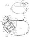
- FIG. 4is a perspective view of a typical cardiac pacemaker embodying the present invention, wherein the RF tag is disposed within the header block.
- FIG. 5is an enlarged perspective view of the RF tag taken generally about the line 5 - 5 from FIG. 4 .
- FIG. 6is a diagrammatic view illustrating the component parts of the RF activated AIMD telemetry transceiver of the present invention.
- FIG. 7is an electrical schematic of the circuitry illustrated in FIG. 6 .
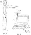
- FIG. 8is a system diagram illustrating operation of the present invention.
- FIG. 9is a system illustration similar to FIG. 8 , except that an older style of external program is shown including a wand which is placed over the patient's AIMD.
- FIGS. 10 and 11are similar to FIGS. 8 and 9 , illustrating that the RFID reader/interrogator can be incorporated either within or connected to the AIMD external programmer.
- the present inventionin a broad sense, relates to an RF activated AIMD telemetry transceiver which includes (1) a telemetry transceiver associated with an AIMD, having an active telemetry mode wherein the telemetry transceiver is powered by the AIMD, and a sleep mode; (2) a passive RF tag associated with the telemetry transceiver; and (3) a telemetry wake-up circuit electrically disposed between the telemetry transceiver and the passive RF tag.
- the telemetry wake-up circuitis responsive to a signal from the RF tag to place the telemetry transceiver in the active telemetry mode.
- the AIMD transceiverhas a timer wherein it returns to its sleep mode after a predetermined amount of time.
- a remote AIMD programmermay send a signal to the AIMD telemetry antenna and associated transceiver telling it to turn off and return to its sleep mode.
- the remote AIMD programmercan incorporate a low frequency (LF) RF transmitter or RFID reader/interrogator operating in the 50 to 135 KHz frequency range which would transmit a signal sufficient to penetrate right through the titanium housing of an AIMD and activate an embedded passive RF chip.
- the circuitry of the RF chipwould be connected to telemetry circuits contained within the AIMD. For example, in the case of a pacemaker, the remote pacemaker programmer would send the RF signal as a wake-up call to turn on the AIMD telemetry receiving circuits so that the pacemaker could communicate with the remote AIMD programmer.
- LFlow frequency
- the RF chipis a four terminal RFID chip.
- RFIDis widely used for inventory and article tracking. RFID operational protocols and frequencies have evolved worldwide.
- EPC and ISO standardsand also ANSI standards that cover the frequency band, forms of modulation, etc.
- the ISO 18,000 standardsare particularly applicable to the present invention.
- low frequency RFID systems operating below 135 kHzare governed by ISO 18,000-2.
- EPC Globalwhich defines various UHF and HF RFID protocols.
- EPC HF Class 1covers 13.56 MHz. 13.56 MHz is also known as the RFID HF band and is covered by ISO 18,000-3.
- the use of a passive four terminal RFID tag for the present inventionis preferred because the frequency allocations and other protocols have been worked out over the last couple of decades and have resolved themselves into these international standards.
- the passive RFID tagdraws no current at all from the AIMD battery.
- a passive RFID tagis entirely powered from the external reader/interrogator. This is what makes it possible to achieve such very low levels of current drop when the telemetry circuit is in its sleep mode.
- the only part of the AIMD transceiver or receiver that would be active at allis the electronic switch that is coupled to the RFID chip. In the case where this is a field effect transistor (FET) switch, the current draw would be exceedingly low. It is only when the RFID tag itself receives energy from an external source such as an RFID reader/interrogator, that it sends a pulse to activate the transceiver electronic switch, thereby waking up the entire AIMD telemetry transceiver circuitry.
- FETfield effect transistor
- the prior art Zarlink chipshortens a pacemaker battery life by over one month.
- the present inventionwould, in contrast, shorten a pacemaker battery life by only a portion of a single day.
- the RFID tagcan be multifunctional. That is, when it receives a wake-up encoded pulse from an external reader/interrogator, it can act as the described telemetry wake-up trigger. However, by sending it an interrogation pulse, it can also be used to identify the make, model number, and/or identify MRI compatible features of the AIMD.
- FIG. 3is a cross-sectional view taken generally along section 3 - 3 from FIG. 2 .
- a circuit board or substrate 110which contains many electronic components and microelectronic chips which enable the AIMD 100 C to function.
- an RF or RFID tag 112which includes an antenna 114 and a four terminal RF or RFID chip 116 .
- Two of the leadwires that are routed to the RFID chip 116are connected to the antenna 114 .
- leadwires 118 , 120that are connected from the RFID chip 116 to AIMD telemetry transceiver circuitry 122 as shown.
- energyis received from a remote RFID reader/interrogator 124 ( FIG. 6 ) and coupled to the RFID tag 112 antenna 114 .
- a resonant circuitis formed between this antenna 114 and the RFID chip 116 .
- a capacitor 126FIG. 7
- the RFID chip 116receives the proper encoded signal from the reader/interrogator 124 ( FIG. 7 ), it is activated and transmits a wake-up signal via leadwires 118 , 120 to the AIMD telemetry transceiver 122 .
- This wake-up pulseputs the telemetry transceiver 122 into its active mode so that it may communicate with its external/remote programmer 128 ( FIG. 6 ).
- the remote programmer 128may be the older style close-wanded telemetry low frequency magnetic coupling-type ( FIG. 9 ) or it may be the newer RF distance telemetry-type ( FIG. 8 ).
- the RFID tag 112 and its associated component antenna 114 and RFID chip 116need not be biocompatible or hermetic. This is because they are disposed inside the overall electromagnetically shielded and hermetically sealed housing 102 of the AIMD 100 C.
- the obvious advantageis the RFID tag 112 and all its associated components are in an environmentally inert environment and are never exposed to body tissue or body fluids.
- a disadvantageis the fact that the antenna 114 is disposed inside of the electromagnetically shielded housing 102 of the AIMD. This means, the antenna 114 can only effectively pick up low frequency RFID signals. These signals would typically be in the 50 to 135 kHz frequency range. The antenna 114 would be completely ineffective in picking up signals from an external RFID reader/interrogator 124 at HF (13.56 MHz) or higher frequencies. This is because the housing 102 of the AIMD would effectively shield such signals.
- FIG. 4illustrates a cardiac pacemaker 100 C having an RFID tag 112 which is mounted in the AIMD plastic header block 104 .
- the RFID antenna 114would be more efficient because it is outside of the generally electromagnetically shielded housing 102 of the AIMD. Since the antenna 114 that is associated with the RFID tag 112 is now displaced within the plastic header block 104 , it can more effectively pick up signals from the RFID reader/interrogator 124 .
- the RFID frequencycould still be in the low frequency range (LF) generally from 50 to 135 kHz, but it could also be in the HF (13.56 MHz) frequency range or even the UHF frequency bands.
- LFlow frequency range
- HF13.56 MHz
- the RFID tag 112 and its associated chip 116 and antenna 114are placed in the header block 104 , it is important that these components be resistant to body fluids. Over time, body fluids can penetrate through bulk permeability through the header block 104 plastic material. Accordingly, the antenna 114 of the RFID tag 112 must be made of biocompatible material, such as platinum, palladium, niobium and the like. In addition, the RFID chip 116 itself must be either biocompatible or placed within a hermetic package so it is also resistant to body fluids. See U.S. patent application Ser. No. 12/566,223, now U.S. application Pub. No. 2011/0071516, which is incorporated herein by reference.
- Leadwires 118 and 120should also be biocompatible up to the point where they are connected to the hermetic seal 130 . It will be apparent to those skilled in the art. that the hermetic seal 130 for the RFID tag 112 could be incorporated within the overall hermetic seal 132 which is coupled to the IS-1 connectors 106 , 108 and. internal electronic circuits. Leadwires 118 and 120 are routed to leadwires 118 ′ and 120 ′ within the AIMD housing 102 and are connected to the telemetry transceiver 122 which is disposed on a circuit board 110 .
- FIG. 5shows that the RFID tag 112 of FIG. 4 consists of antenna structure 114 and a hermetically sealed package 132 in which the RFID chip 116 is disposed. Terminals 134 and 136 are connected to the RFID tag's antenna 114 . Leadwires 118 and 120 are routed to the telemetry transceiver 122 which is located inside of the electromagnetically shielded and hermetically sealed AIMD housing 102 .
- the antenna 114 of the RFID tag 112is disposed outside of the hermetic and electromagnetically sealed housing 102 of the AIMD 100 C.
- the RFID chip 116could be disposed inside of the housing 102 of the AIMD, for example, placed on the circuit board 110 adjacent to transceiver chip 122 .
- the antenna 114 of the RFID tag 112would still be disposed outside of the AIMD shielded housing 102 wherein its associated RFID chip and energy storage capacitor 126 are disposed inside the hermetically sealed housing 102 .
- FIG. 6is a diagrammatic view illustrating how the RFID activated AIMD telemetry transceiver of the present invention would operate. Shown is an RFID reader/interrogator 124 . It may be a standalone unit, such as a hand-held RFID reader ( FIGS. 8-10 ) or it could be incorporated within or adjacent to the AIMD remote programmer 128 ( FIG. 11 ). A signal or pulse 138 is produced when the RFID reader/interrogator 124 is activated which couples energy to tuned antenna 114 of the RFID tag 112 . This couples energy to terminals 134 and 136 of the RFID chip 116 which activates the RFID chip.
- the RFID chip 116stores this energy in a capacitor (not shown) which then transmits a wake-up pulse via terminals 140 and 142 to the telemetry wake-up circuit 144 .
- the telemetry wake-up circuit 144then turns power on to the AIMD telemetry transceiver 122 , placing it into an active telemetry mode.
- an optional timer 146which will turn off the telemetry transceiver 122 and put it back into its sleep mode after a predetermined amount of time.
- An alternative to the timer 146is that a second activation of the RFID reader/interrogator 124 would cause the RFID chip 116 to once again be activated so that it sends a toggle pulse back to the telemetry wake-up circuit 144 .
- FIG. 7is an electrical schematic diagram of the system of FIG. 6 , illustrating the components of the telemetry wake-up circuit 144 .
- a bipolar junction transistorBJT
- the transistor 150 base 152receives a signal from the RFID chip 116 from terminals 140 and 142 through leadwires 118 and 120 . This results in a very low voltage drop between the transistor 150 collector C and the emitter E. This effectively connects the telemetry transceiver 122 to voltage source V s and to the ground reference voltage 0V.
- the telemetry transceiver 122which is shown connected to its antenna 158 so that it can receive and transmit information from the AIMD remote programmer 128 ( FIG. 6 ).
- the voltage source V sis normally supplied from the AIMD internal battery 154 ( FIG. 3 ).
- the N-P-N transceiver switch 150is illustrative of any type of microelectronic switch.
- the RFID chip 116 of the present inventioncontains at least four terminals. Two of these terminals 134 , 136 are reserved for connection to the antenna 114 and its associated resonating capacitor 126 . The other two or more terminals 140 , 142 are for connection to AIMD telemetry transceiver circuits 118 , 120 in order to provide both wake-up and go back to sleep pulses.
- FIG. 8illustrates the operation of the present invention. Shown is a human patient 156 who has an AIMD 100 . In its normal operating mode, the AIMD's telemetry transceiver circuits would be in a sleep or quiescent low battery drain mode.
- a signal 138is transmitted by an RFID reader/interrogator 124 . This pulse 138 is coupled to the RFID tag 112 that is associated with the AIMD 100 . The RFID signal 138 then wakes up the AIMD's telemetry transceiver 122 . It is at this point that the remote programmer 128 can form a two-way communication link between the AIMD 100 and the programmer 128 . In the case shown in FIG. 8 , the remote programmer 128 has an antenna 158 , which is an RF antenna.
- One popular set of frequenciesis the MICS band operating in the 402 to 405 MHz frequency range.
- the telemetry transceiver of the AIMD 100can be put back into its wake-up mode in a number of ways, including an internal timer circuit 146 , receipt of a second type of RFID pulse 138 ′ which will instruct the RFID chip 116 to unlatch the telemetry wake-up circuit thereby putting the telemetry transceiver back into its sleep mode, or even by transmission of a special pulse sequence 160 from the remote programmer 128 which instructs the transceiver 122 to go back into its sleep mode.
- FIG. 9is very similar to FIG. 8 , except that an older style of remote programmer 128 is shown which includes a wand 162 which is placed over the patient's AIMD 100 .
- the wand 162is generally connected through leads 164 to the remote programmer 128 .
- This type of wanded telemetryinvolves a close coupled low frequency magnetic link between an antenna in the wand 162 and an associated multi-turn loop antenna associated with the AIMD 100 .
- the wand 162would be placed either very close to or directly on the patient's chest directly over the AIMD 100 . This is the case for a cardiac pacemaker 100 C.
- the AIMD 100could be located anywhere within the human body in which case the wand 162 would have to be placed over it.
- the system of FIG. 9operates in all ways as previously described in connection with FIG. 8 .
- FIGS. 10 and 11are similar to FIGS. 8 and 9 , however in this case, the RFID reader 124 , which is illustrated in FIG. 10 , can be incorporated either within or connected to the AIMD remote programmer 128 .
- an RF-activated AIMD telemetry transceiverwhich includes a telemetry transceiver associated with the AIMD, an RF tag associated with the telemetry transceiver, and a telemetry wake-up circuit electrically disposed between the telemetry transceiver and the RF tag.
- the RF tagcomprises a passive RF chip and an antenna.
- the antennais biocompatible and the RF chip is disposed within a hermetic package.
- the telemetry transceiverhas an active telemetry mode wherein a telemetry transceiver is powered by the AIMD, and a sleep mode.
- the telemetry wake-up circuitis responsive to a signal from the RF tag to place the telemetry transceiver into the active telemetry mode.
Landscapes
- Health & Medical Sciences (AREA)
- Life Sciences & Earth Sciences (AREA)
- Engineering & Computer Science (AREA)
- Surgery (AREA)
- Physics & Mathematics (AREA)
- Veterinary Medicine (AREA)
- Biomedical Technology (AREA)
- Public Health (AREA)
- General Health & Medical Sciences (AREA)
- Animal Behavior & Ethology (AREA)
- Nuclear Medicine, Radiotherapy & Molecular Imaging (AREA)
- Pathology (AREA)
- Medical Informatics (AREA)
- Heart & Thoracic Surgery (AREA)
- Molecular Biology (AREA)
- Radiology & Medical Imaging (AREA)
- Oral & Maxillofacial Surgery (AREA)
- Electromagnetism (AREA)
- Biophysics (AREA)
- Theoretical Computer Science (AREA)
- Computer Networks & Wireless Communication (AREA)
- General Physics & Mathematics (AREA)
- Microelectronics & Electronic Packaging (AREA)
- Acoustics & Sound (AREA)
- Computer Hardware Design (AREA)
- Electrotherapy Devices (AREA)
Abstract
Description
Claims (27)
Priority Applications (2)
| Application Number | Priority Date | Filing Date | Title |
|---|---|---|---|
| US12/719,630US8761895B2 (en) | 2008-03-20 | 2010-03-08 | RF activated AIMD telemetry transceiver |
| US12/871,201US8321032B2 (en) | 2006-11-09 | 2010-08-30 | RFID-enabled AIMD programmer system for identifying MRI compatibility of implanted leads |
Applications Claiming Priority (7)
| Application Number | Priority Date | Filing Date | Title |
|---|---|---|---|
| US3838208P | 2008-03-20 | 2008-03-20 | |
| US11609408P | 2008-11-19 | 2008-11-19 | |
| US14410209P | 2009-01-12 | 2009-01-12 | |
| US15006109P | 2009-02-05 | 2009-02-05 | |
| US12/407,402US8195295B2 (en) | 2008-03-20 | 2009-03-19 | Shielded three-terminal flat-through EMI/energy dissipating filter |
| US12/566,223US8253555B2 (en) | 2006-01-25 | 2009-09-24 | Miniature hermetically sealed RFID microelectronic chip connected to a biocompatible RFID antenna for use in conjunction with an AIMD |
| US12/719,630US8761895B2 (en) | 2008-03-20 | 2010-03-08 | RF activated AIMD telemetry transceiver |
Related Parent Applications (2)
| Application Number | Title | Priority Date | Filing Date |
|---|---|---|---|
| US12/407,402Continuation-In-PartUS8195295B2 (en) | 2001-04-13 | 2009-03-19 | Shielded three-terminal flat-through EMI/energy dissipating filter |
| US12/566,223Continuation-In-PartUS8253555B2 (en) | 2006-01-25 | 2009-09-24 | Miniature hermetically sealed RFID microelectronic chip connected to a biocompatible RFID antenna for use in conjunction with an AIMD |
Related Child Applications (1)
| Application Number | Title | Priority Date | Filing Date |
|---|---|---|---|
| US11/943,470Continuation-In-PartUS7787958B2 (en) | 2001-04-13 | 2007-11-20 | RFID detection and identification system for implantable medical lead systems |
Publications (2)
| Publication Number | Publication Date |
|---|---|
| US20100185263A1 US20100185263A1 (en) | 2010-07-22 |
| US8761895B2true US8761895B2 (en) | 2014-06-24 |
Family
ID=42337558
Family Applications (1)
| Application Number | Title | Priority Date | Filing Date |
|---|---|---|---|
| US12/719,630Expired - Fee RelatedUS8761895B2 (en) | 2006-11-09 | 2010-03-08 | RF activated AIMD telemetry transceiver |
Country Status (1)
| Country | Link |
|---|---|
| US (1) | US8761895B2 (en) |
Cited By (8)
| Publication number | Priority date | Publication date | Assignee | Title |
|---|---|---|---|---|
| US10874865B2 (en) | 2017-11-06 | 2020-12-29 | Avx Corporation | EMI feedthrough filter terminal assembly containing a resin coating over a hermetically sealing material |
| US11116975B2 (en) | 2015-11-09 | 2021-09-14 | Bluewind Medical Ltd. | Optimization of application of current |
| US11213685B2 (en) | 2017-06-13 | 2022-01-04 | Bluewind Medical Ltd. | Antenna configuration |
| US11278719B2 (en) | 2012-12-06 | 2022-03-22 | Bluewind Medical Ltd. | Delivery of implantable neurostimulators |
| US11400299B1 (en) | 2021-09-14 | 2022-08-02 | Rainbow Medical Ltd. | Flexible antenna for stimulator |
| US11439833B2 (en) | 2016-11-23 | 2022-09-13 | Bluewind Medical Ltd. | Implant-delivery tool |
| US11648410B2 (en) | 2012-01-26 | 2023-05-16 | Bluewind Medical Ltd. | Wireless neurostimulators |
| US12246183B1 (en) | 2023-10-06 | 2025-03-11 | Greatbatch Ltd. | Self-centering polymeric washer that prevents misalignment when positioned between a feedthrough and a circuit board supporting EMI filter capacitors for a medical device |
Families Citing this family (11)
| Publication number | Priority date | Publication date | Assignee | Title |
|---|---|---|---|---|
| US8244370B2 (en) | 2001-04-13 | 2012-08-14 | Greatbatch Ltd. | Band stop filter employing a capacitor and an inductor tank circuit to enhance MRI compatibility of active medical devices |
| US8219208B2 (en) | 2001-04-13 | 2012-07-10 | Greatbatch Ltd. | Frequency selective passive component networks for active implantable medical devices utilizing an energy dissipating surface |
| US20070088416A1 (en)* | 2001-04-13 | 2007-04-19 | Surgi-Vision, Inc. | Mri compatible medical leads |
| US8115600B2 (en) | 2008-11-19 | 2012-02-14 | Greatbatch Ltd. | RFID detection and identification system including an RFID reader having a limited transmit time and a time-out period to protect a medical device against RFID-associated electromagnetic interference |
| CA2715015A1 (en)* | 2008-03-17 | 2009-09-24 | Surgivision, Inc. | Low profile medical devices with internal drive shafts that cooperate with releasably engageable drive tools and related methods |
| US8299899B2 (en)* | 2008-11-19 | 2012-10-30 | Greatbatch Ltd. | AIMD external programmer incorporating a multifunction RFID reader having a limited transmit time and a time-out period |
| DK2621339T3 (en) | 2010-09-29 | 2020-02-24 | Dexcom Inc | ADVANCED SYSTEM FOR CONTINUOUS ANALYTICAL MONITORING |
| US9766684B2 (en)* | 2014-07-21 | 2017-09-19 | Apple Inc. | Telemetry for power and thermal management |
| US9749311B2 (en) | 2014-09-24 | 2017-08-29 | Oracle International Corporation | Policy based compliance management and remediation of devices in an enterprise system |
| CA2973192C (en)* | 2015-01-09 | 2023-04-04 | Axonics Modulation Technologies, Inc. | Improved antenna and methods of use for an implantable nerve stimulator |
| US11350857B2 (en) | 2018-05-03 | 2022-06-07 | Dexcom, Inc. | Systems and methods for activating analyte sensor electronics |
Citations (102)
| Publication number | Priority date | Publication date | Assignee | Title |
|---|---|---|---|---|
| US3681612A (en) | 1970-06-19 | 1972-08-01 | Siemens Ag | Device for eliminating interference between conductors of high frequency signals |
| US3745430A (en) | 1971-12-21 | 1973-07-10 | Motorola Inc | Thick film feed-through capacitor |
| US4376441A (en) | 1980-10-14 | 1983-03-15 | Theodore Duncan | Hair treatment applicator |
| US4424551A (en) | 1982-01-25 | 1984-01-03 | U.S. Capacitor Corporation | Highly-reliable feed through/filter capacitor and method for making same |
| US4846158A (en) | 1986-06-06 | 1989-07-11 | Akihiko Teranishi | Hand type electric massage machine |
| US4858064A (en) | 1987-10-29 | 1989-08-15 | Kabushiki Kaisha Toshiba | Thick-film high frequency signal circuit apparatus with feedthrough capacitor |
| EP0534782A1 (en) | 1991-09-26 | 1993-03-31 | Medtronic, Inc. | Implantable medical device enclosure |
| US5268810A (en) | 1993-01-08 | 1993-12-07 | Honeywell Inc. | Electrical connector incorporating EMI filter |
| JPH06176962A (en) | 1992-12-10 | 1994-06-24 | Tdk Corp | Feedthrough type laminated ceramic capacitor |
| US5331505A (en) | 1993-01-08 | 1994-07-19 | Honeywell Inc. | Multi-coplanar capacitor for electrical connector |
| US5333095A (en) | 1993-05-03 | 1994-07-26 | Maxwell Laboratories, Inc., Sierra Capacitor Filter Division | Feedthrough filter capacitor assembly for human implant |
| US5336158A (en) | 1992-11-12 | 1994-08-09 | Huggins Freddie L | Pneumatic vacuum vibrator apparatus |
| EP0619101A1 (en) | 1993-02-01 | 1994-10-12 | C.R. Bard, Inc. | Implantable inductively coupled medical identification system |
| US5450090A (en) | 1994-07-20 | 1995-09-12 | The Charles Stark Draper Laboratory, Inc. | Multilayer miniaturized microstrip antenna |
| US5491300A (en) | 1994-04-28 | 1996-02-13 | Cray Computer Corporation | Penetrator and flexible circuit assembly for sealed environment |
| US5493259A (en) | 1992-10-13 | 1996-02-20 | The Whitaker Corporation | High voltage, low pass filtering connector with multiple ground planes |
| WO1996011722A1 (en) | 1994-10-12 | 1996-04-25 | Ael Industries, Inc. | Telemetry system for an implanted device |
| US5620476A (en) | 1995-11-13 | 1997-04-15 | Pacesetter, Inc. | Implantable medical device having shielded and filtered feedthrough assembly and methods for making such assembly |
| US5650759A (en) | 1995-11-09 | 1997-07-22 | Hittman Materials & Medical Components, Inc. | Filtered feedthrough assembly having a mounted chip capacitor for medical implantable devices and method of manufacture therefor |
| US5757252A (en) | 1995-08-31 | 1998-05-26 | Itt Industries, Inc. | Wide frequency band transition between via RF transmission lines and planar transmission lines |
| US5765779A (en) | 1995-02-15 | 1998-06-16 | Dunlop Limited | Ice protection device |
| US5782891A (en) | 1994-06-16 | 1998-07-21 | Medtronic, Inc. | Implantable ceramic enclosure for pacing, neurological, and other medical applications in the human body |
| US5822174A (en) | 1995-07-21 | 1998-10-13 | Matsushita Electric Industrial Co., Ltd. | Multilayer feedthrough capacitor |
| US5855609A (en) | 1992-08-24 | 1999-01-05 | Lipomatrix, Incorporated (Bvi) | Medical information transponder implant and tracking system |
| US5905627A (en) | 1997-09-10 | 1999-05-18 | Maxwell Energy Products, Inc. | Internally grounded feedthrough filter capacitor |
| US5959336A (en) | 1996-08-26 | 1999-09-28 | Advanced Micro Devices, Inc. | Decoder circuit with short channel depletion transistors |
| US5973906A (en) | 1998-03-17 | 1999-10-26 | Maxwell Energy Products, Inc. | Chip capacitors and chip capacitor electromagnetic interference filters |
| US5973907A (en) | 1997-09-05 | 1999-10-26 | Kemet Electronics Corp. | Multiple element capacitor |
| US6137161A (en) | 1999-09-14 | 2000-10-24 | International Business Machines Corporation | Interposer array module for capacitive decoupling and filtering |
| US6146743A (en) | 1997-02-21 | 2000-11-14 | Medtronic, Inc. | Barrier metallization in ceramic substrate for implantable medical devices |
| JP2001068958A (en) | 1999-08-31 | 2001-03-16 | Kyocera Corp | Low-pass filter and circuit board |
| US6216038B1 (en) | 1998-04-29 | 2001-04-10 | Medtronic, Inc. | Broadcast audible sound communication of programming change in an implantable medical device |
| US6259937B1 (en) | 1997-09-12 | 2001-07-10 | Alfred E. Mann Foundation | Implantable substrate sensor |
| US6275369B1 (en) | 1997-11-13 | 2001-08-14 | Robert A. Stevenson | EMI filter feedthough terminal assembly having a capture flange to facilitate automated assembly |
| US6342839B1 (en) | 1998-03-09 | 2002-01-29 | Aginfolink Holdings Inc. | Method and apparatus for a livestock data collection and management system |
| US6373673B1 (en) | 1997-04-08 | 2002-04-16 | X2Y Attenuators, Llc | Multi-functional energy conditioner |
| US6375780B1 (en) | 1992-06-17 | 2002-04-23 | Micron Technology, Inc. | Method of manufacturing an enclosed transceiver |
| US6424234B1 (en) | 1998-09-18 | 2002-07-23 | Greatbatch-Sierra, Inc. | Electromagnetic interference (emi) filter and process for providing electromagnetic compatibility of an electronic device while in the presence of an electromagnetic emitter operating at the same frequency |
| US6456481B1 (en) | 2001-05-31 | 2002-09-24 | Greatbatch-Sierra, Inc. | Integrated EMI filter-DC blocking capacitor |
| US6459935B1 (en) | 2000-07-13 | 2002-10-01 | Avx Corporation | Integrated filter feed-thru |
| US20020151770A1 (en) | 2001-01-04 | 2002-10-17 | Noll Austin F. | Implantable medical device with sensor |
| US6473314B1 (en) | 2000-08-03 | 2002-10-29 | Powerwave Technologies, Inc. | RF power amplifier assembly employing multi-layer RF blocking filter |
| US6529103B1 (en) | 2000-09-07 | 2003-03-04 | Greatbatch-Sierra, Inc. | Internally grounded feedthrough filter capacitor with improved ground plane design for human implant and other applications |
| US20030114897A1 (en)* | 2001-12-19 | 2003-06-19 | Von Arx Jeffrey A. | Implantable medical device with two or more telemetry systems |
| US6660116B2 (en) | 2000-03-01 | 2003-12-09 | Medtronic, Inc. | Capacitive filtered feedthrough array for an implantable medical device |
| US20030229383A1 (en)* | 2002-06-11 | 2003-12-11 | Whitehurst Todd K. | RF telemetry link for establishment and maintenance of communications with an implantable device |
| US6735479B2 (en) | 2000-06-14 | 2004-05-11 | Medtronic, Inc. | Lifestyle management system |
| US6765779B2 (en) | 2002-02-28 | 2004-07-20 | Greatbatch-Sierra, Inc. | EMI feedthrough filter terminal assembly for human implant applications utilizing oxide resistant biostable conductive pads for reliable electrical attachments |
| JP2004254257A (en) | 2002-12-26 | 2004-09-09 | Kyocera Corp | Wiring board with built-in low-pass filter |
| JP2004289760A (en) | 2003-01-29 | 2004-10-14 | Kyocera Corp | Wiring board with built-in low-pass filter |
| US6806806B2 (en) | 1999-01-28 | 2004-10-19 | X2Y Attenuators, Llc | Polymer fuse and filter apparatus |
| US20050043594A1 (en)* | 2003-08-18 | 2005-02-24 | Dinsmoor David A. | System and apparatus for remote activation of implantable medical devices |
| JP2005117606A (en) | 2003-10-08 | 2005-04-28 | Samsung Electro Mech Co Ltd | Laminated low pass filter |
| US20050165317A1 (en)* | 2003-11-04 | 2005-07-28 | Turner Nicholas M. | Medical devices |
| US20050201039A1 (en) | 2003-05-23 | 2005-09-15 | Stevenson Robert A. | Inductor capacitor EMI filter for human implant applications |
| US6957107B2 (en) | 2002-03-13 | 2005-10-18 | Cardionet, Inc. | Method and apparatus for monitoring and communicating with an implanted medical device |
| US20060032665A1 (en) | 2004-07-09 | 2006-02-16 | Ice Donald A | Single layer flex circuit |
| US7017822B2 (en) | 2001-02-15 | 2006-03-28 | Integral Technologies, Inc. | Low cost RFID antenna manufactured from conductive loaded resin-based materials |
| US20060085043A1 (en) | 2004-04-15 | 2006-04-20 | Greatbatch-Sierra, Inc. | Apparatus and process for reducing the susceptibility of active implantable medical devices to medical procedures such as magentic resonance imaging |
| US7038900B2 (en) | 2003-02-27 | 2006-05-02 | Greatbatch-Sierra, Inc. | EMI filter terminal assembly with wire bond pads for human implant applications |
| US7110227B2 (en) | 1997-04-08 | 2006-09-19 | X2Y Attenuators, Llc | Universial energy conditioning interposer with circuit architecture |
| US20060212096A1 (en) | 2005-03-21 | 2006-09-21 | Greatbatch-Sierra, Inc. | Rfid detection and identification system for implantable medical devices |
| US7113387B2 (en) | 2002-02-28 | 2006-09-26 | Greatbatch-Sierra, Inc. | EMI filter capacitors designed for direct body fluid exposure |
| US7199995B2 (en) | 2005-08-15 | 2007-04-03 | Greatbatch-Sierra, Inc. | Feedthrough filter capacitor assembly with internally grounded hermetic insulator |
| US20070112398A1 (en) | 2005-11-11 | 2007-05-17 | Greatbatch Ltd. | Tank filters placed in series with the lead wires or circuits of active medical devices to enhance mri compatibility |
| JP2007129565A (en) | 2005-11-04 | 2007-05-24 | Alps Electric Co Ltd | Low-pass filter |
| US20070123949A1 (en) | 2005-11-11 | 2007-05-31 | Greatbatch Ltd. | Low loss band pass filter for rf distance telemetry pin antennas of active implantable medical devices |
| US7236834B2 (en) | 2003-12-19 | 2007-06-26 | Medtronic, Inc. | Electrical lead body including an in-line hermetic electronic package and implantable medical device using the same |
| US7240833B2 (en) | 2004-05-20 | 2007-07-10 | Cardiac Pacemakers, Inc. | System and method of managing information for an implantable medical device |
| US20070203529A1 (en) | 2006-02-28 | 2007-08-30 | Iyer Rajesh V | Filtered feedthrough assembly |
| US7301748B2 (en) | 1997-04-08 | 2007-11-27 | Anthony Anthony A | Universal energy conditioning interposer with circuit architecture |
| US20070288058A1 (en) | 2001-04-13 | 2007-12-13 | Greatbatch Ltd. | Band stop filter employing a capacitor and an inductor tank circuit to enhance mri compatibility of active implantable medical devices |
| US7322832B2 (en) | 2004-10-26 | 2008-01-29 | Medtronic, Inc. | Radio frequency antenna flexible circuit interconnect with unique micro connectors |
| US7327553B2 (en) | 2004-07-27 | 2008-02-05 | Brendel Richard L | Feedthrough capacitor filter assemblies with laminar flow delaminations for helium leak detection |
| US7333013B2 (en) | 2004-05-07 | 2008-02-19 | Berger J Lee | Medical implant device with RFID tag and method of identification of device |
| US20080049410A1 (en) | 2006-06-30 | 2008-02-28 | Toshiyuki Kawaguchi | Noise-suppressing wiring-member and printed wiring board |
| US20080049376A1 (en) | 1998-11-04 | 2008-02-28 | Greatbatch Ltd. | Non-ferromagnetic tank filters in lead wires of active implantable medical devices to enhance mri compatibility |
| US20080065181A1 (en) | 2001-04-13 | 2008-03-13 | Greatbatch, Ltd. | Rfid detection and identification system for implantable medical lead systems |
| US20080071313A1 (en) | 2005-11-11 | 2008-03-20 | Greatbatch Ltd. | Tank filters utilizing very low k materials, in series with lead wires or circuits of active medical devices to enhance mri compatibility |
| US20080116997A1 (en) | 2001-04-13 | 2008-05-22 | Greatbatch Ltd. | Cylindrical bandstop filters for medical lead systems |
| US20080132987A1 (en) | 2001-04-13 | 2008-06-05 | Greatbatch Ltd. | Medical lead system utilizing electromagnetic bandstop filters |
| US20080161886A1 (en) | 2006-06-08 | 2008-07-03 | Greatbatch Ltd. | Tank filters adaptable for placement with a guide wire, in series with the lead wires or circuits of active medical devices to enhance mri compatibility |
| US20080195180A1 (en) | 2006-06-08 | 2008-08-14 | Greatbatch Ltd. | Low loss band pass filter for rf distance telemetry pin antennas of active implantable medical devices |
| US7423860B2 (en) | 1997-04-08 | 2008-09-09 | X2Y Attenuators, Llc | Multi-functional energy conditioner |
| US7428136B2 (en) | 2005-08-06 | 2008-09-23 | Geomat Insights, Llc | Integral charge storage basement and wideband embedded decoupling structure for integrated circuit |
| US20080239622A1 (en) | 2007-03-30 | 2008-10-02 | Industrial Technology Research Institute | Wiring structure of laminated capacitors |
| US7433168B2 (en) | 2000-10-17 | 2008-10-07 | X2Y Attenuators, Llc | Amalgam of shielding and shielded energy pathways and other elements for single or multiple circuitries with common reference node |
| US20080247111A1 (en) | 1997-04-08 | 2008-10-09 | Anthony Anthony | Arrangement for Energy Conditioning |
| US20080247116A1 (en) | 2007-04-06 | 2008-10-09 | Ibiden Co., Ltd | Interposer, a method for manufacturing the same and an electronic circuit package |
| US20080247117A1 (en) | 2007-04-03 | 2008-10-09 | Ralph Elam | filtering assembly and a feedthrough assembly |
| US7436672B2 (en) | 2004-09-28 | 2008-10-14 | Mitsubishi Denki Kabushiki Kaisha | Semiconductor device and method of manufacture thereof |
| US7439449B1 (en) | 2002-02-14 | 2008-10-21 | Finisar Corporation | Flexible circuit for establishing electrical connectivity with optical subassembly |
| US20080264685A1 (en) | 2007-04-30 | 2008-10-30 | Samsung Electro-Mechanics Co., Ltd. | Electromagnetic bandgap structure and printed circuit board |
| US7446996B2 (en) | 2006-12-13 | 2008-11-04 | Tdk Corporation | Feedthrough capacitor array |
| US7450396B2 (en) | 2006-09-28 | 2008-11-11 | Intel Corporation | Skew compensation by changing ground parasitic for traces |
| US20080277153A1 (en) | 2004-08-24 | 2008-11-13 | Abeye Teshome | System and Method for Capacitive Coupled VIA Structures in Information Handling System Circuit Boards |
| US7479108B2 (en) | 2002-01-29 | 2009-01-20 | Sicel Technologies, Inc. | Methods for using an implantable sensor unit |
| US20090107717A1 (en) | 2007-10-26 | 2009-04-30 | Industrial Technology Research Institute | Electrically conductive structure of circuit board and circuit board using the same |
| US20090128976A1 (en) | 2000-10-17 | 2009-05-21 | Anthony William M | Energy Pathway Arrangements for Energy Conditioning |
| US20090139760A1 (en) | 2007-11-30 | 2009-06-04 | Ibiden Co., Ltd | Multilayer printed wiring board and method of manufacturing the same |
| US20090180237A1 (en) | 2004-09-27 | 2009-07-16 | Taiwan Semiconductor Manufacturing Co., Ltd. | De-coupling capacitors produced by utilizing dummy conductive structures integrated circuits |
| US20090187229A1 (en) | 2007-04-11 | 2009-07-23 | Pacesetter, Inc. | Capacitor-integrated feedthrough assembly with improved grounding for an implantable medical device |
Family Cites Families (1)
| Publication number | Priority date | Publication date | Assignee | Title |
|---|---|---|---|---|
| US8760413B2 (en)* | 2009-01-08 | 2014-06-24 | Synaptics Incorporated | Tactile surface |
- 2010
- 2010-03-08USUS12/719,630patent/US8761895B2/ennot_activeExpired - Fee Related
Patent Citations (110)
| Publication number | Priority date | Publication date | Assignee | Title |
|---|---|---|---|---|
| US3681612A (en) | 1970-06-19 | 1972-08-01 | Siemens Ag | Device for eliminating interference between conductors of high frequency signals |
| US3745430A (en) | 1971-12-21 | 1973-07-10 | Motorola Inc | Thick film feed-through capacitor |
| US4376441A (en) | 1980-10-14 | 1983-03-15 | Theodore Duncan | Hair treatment applicator |
| US4424551A (en) | 1982-01-25 | 1984-01-03 | U.S. Capacitor Corporation | Highly-reliable feed through/filter capacitor and method for making same |
| US4424551B1 (en) | 1982-01-25 | 1991-06-11 | Highly-reliable feed through/filter capacitor and method for making same | |
| US4846158A (en) | 1986-06-06 | 1989-07-11 | Akihiko Teranishi | Hand type electric massage machine |
| US4858064A (en) | 1987-10-29 | 1989-08-15 | Kabushiki Kaisha Toshiba | Thick-film high frequency signal circuit apparatus with feedthrough capacitor |
| EP0534782A1 (en) | 1991-09-26 | 1993-03-31 | Medtronic, Inc. | Implantable medical device enclosure |
| US6375780B1 (en) | 1992-06-17 | 2002-04-23 | Micron Technology, Inc. | Method of manufacturing an enclosed transceiver |
| US5855609A (en) | 1992-08-24 | 1999-01-05 | Lipomatrix, Incorporated (Bvi) | Medical information transponder implant and tracking system |
| US5493259A (en) | 1992-10-13 | 1996-02-20 | The Whitaker Corporation | High voltage, low pass filtering connector with multiple ground planes |
| US5336158A (en) | 1992-11-12 | 1994-08-09 | Huggins Freddie L | Pneumatic vacuum vibrator apparatus |
| JPH06176962A (en) | 1992-12-10 | 1994-06-24 | Tdk Corp | Feedthrough type laminated ceramic capacitor |
| US5268810A (en) | 1993-01-08 | 1993-12-07 | Honeywell Inc. | Electrical connector incorporating EMI filter |
| US5331505A (en) | 1993-01-08 | 1994-07-19 | Honeywell Inc. | Multi-coplanar capacitor for electrical connector |
| EP0619101A1 (en) | 1993-02-01 | 1994-10-12 | C.R. Bard, Inc. | Implantable inductively coupled medical identification system |
| US5333095A (en) | 1993-05-03 | 1994-07-26 | Maxwell Laboratories, Inc., Sierra Capacitor Filter Division | Feedthrough filter capacitor assembly for human implant |
| US5491300A (en) | 1994-04-28 | 1996-02-13 | Cray Computer Corporation | Penetrator and flexible circuit assembly for sealed environment |
| US5782891A (en) | 1994-06-16 | 1998-07-21 | Medtronic, Inc. | Implantable ceramic enclosure for pacing, neurological, and other medical applications in the human body |
| US5450090A (en) | 1994-07-20 | 1995-09-12 | The Charles Stark Draper Laboratory, Inc. | Multilayer miniaturized microstrip antenna |
| WO1996011722A1 (en) | 1994-10-12 | 1996-04-25 | Ael Industries, Inc. | Telemetry system for an implanted device |
| US5765779A (en) | 1995-02-15 | 1998-06-16 | Dunlop Limited | Ice protection device |
| US5822174A (en) | 1995-07-21 | 1998-10-13 | Matsushita Electric Industrial Co., Ltd. | Multilayer feedthrough capacitor |
| US5757252A (en) | 1995-08-31 | 1998-05-26 | Itt Industries, Inc. | Wide frequency band transition between via RF transmission lines and planar transmission lines |
| US5650759A (en) | 1995-11-09 | 1997-07-22 | Hittman Materials & Medical Components, Inc. | Filtered feedthrough assembly having a mounted chip capacitor for medical implantable devices and method of manufacture therefor |
| US5620476A (en) | 1995-11-13 | 1997-04-15 | Pacesetter, Inc. | Implantable medical device having shielded and filtered feedthrough assembly and methods for making such assembly |
| US5683435A (en) | 1995-11-13 | 1997-11-04 | Pacesetter, Inc. | Implantable medical device having shielded and filtered feedthrough assembly and methods for making such assembly |
| US5959336A (en) | 1996-08-26 | 1999-09-28 | Advanced Micro Devices, Inc. | Decoder circuit with short channel depletion transistors |
| US6146743A (en) | 1997-02-21 | 2000-11-14 | Medtronic, Inc. | Barrier metallization in ceramic substrate for implantable medical devices |
| US7110227B2 (en) | 1997-04-08 | 2006-09-19 | X2Y Attenuators, Llc | Universial energy conditioning interposer with circuit architecture |
| US20080158746A1 (en) | 1997-04-08 | 2008-07-03 | Anthony Anthony A | Universal Energy Conditioning Interposer with Circuit Architecture |
| US7423860B2 (en) | 1997-04-08 | 2008-09-09 | X2Y Attenuators, Llc | Multi-functional energy conditioner |
| US20080247111A1 (en) | 1997-04-08 | 2008-10-09 | Anthony Anthony | Arrangement for Energy Conditioning |
| US7301748B2 (en) | 1997-04-08 | 2007-11-27 | Anthony Anthony A | Universal energy conditioning interposer with circuit architecture |
| US6373673B1 (en) | 1997-04-08 | 2002-04-16 | X2Y Attenuators, Llc | Multi-functional energy conditioner |
| US5973907A (en) | 1997-09-05 | 1999-10-26 | Kemet Electronics Corp. | Multiple element capacitor |
| US5905627A (en) | 1997-09-10 | 1999-05-18 | Maxwell Energy Products, Inc. | Internally grounded feedthrough filter capacitor |
| US6259937B1 (en) | 1997-09-12 | 2001-07-10 | Alfred E. Mann Foundation | Implantable substrate sensor |
| US6275369B1 (en) | 1997-11-13 | 2001-08-14 | Robert A. Stevenson | EMI filter feedthough terminal assembly having a capture flange to facilitate automated assembly |
| US6342839B1 (en) | 1998-03-09 | 2002-01-29 | Aginfolink Holdings Inc. | Method and apparatus for a livestock data collection and management system |
| US5973906A (en) | 1998-03-17 | 1999-10-26 | Maxwell Energy Products, Inc. | Chip capacitors and chip capacitor electromagnetic interference filters |
| US6216038B1 (en) | 1998-04-29 | 2001-04-10 | Medtronic, Inc. | Broadcast audible sound communication of programming change in an implantable medical device |
| US6424234B1 (en) | 1998-09-18 | 2002-07-23 | Greatbatch-Sierra, Inc. | Electromagnetic interference (emi) filter and process for providing electromagnetic compatibility of an electronic device while in the presence of an electromagnetic emitter operating at the same frequency |
| US20080049376A1 (en) | 1998-11-04 | 2008-02-28 | Greatbatch Ltd. | Non-ferromagnetic tank filters in lead wires of active implantable medical devices to enhance mri compatibility |
| US6806806B2 (en) | 1999-01-28 | 2004-10-19 | X2Y Attenuators, Llc | Polymer fuse and filter apparatus |
| JP2001068958A (en) | 1999-08-31 | 2001-03-16 | Kyocera Corp | Low-pass filter and circuit board |
| US6137161A (en) | 1999-09-14 | 2000-10-24 | International Business Machines Corporation | Interposer array module for capacitive decoupling and filtering |
| US6660116B2 (en) | 2000-03-01 | 2003-12-09 | Medtronic, Inc. | Capacitive filtered feedthrough array for an implantable medical device |
| US6735479B2 (en) | 2000-06-14 | 2004-05-11 | Medtronic, Inc. | Lifestyle management system |
| US6459935B1 (en) | 2000-07-13 | 2002-10-01 | Avx Corporation | Integrated filter feed-thru |
| US6473314B1 (en) | 2000-08-03 | 2002-10-29 | Powerwave Technologies, Inc. | RF power amplifier assembly employing multi-layer RF blocking filter |
| US6566978B2 (en) | 2000-09-07 | 2003-05-20 | Greatbatch-Sierra, Inc. | Feedthrough capacitor filter assemblies with leak detection vents |
| US6529103B1 (en) | 2000-09-07 | 2003-03-04 | Greatbatch-Sierra, Inc. | Internally grounded feedthrough filter capacitor with improved ground plane design for human implant and other applications |
| US7433168B2 (en) | 2000-10-17 | 2008-10-07 | X2Y Attenuators, Llc | Amalgam of shielding and shielded energy pathways and other elements for single or multiple circuitries with common reference node |
| US20090128976A1 (en) | 2000-10-17 | 2009-05-21 | Anthony William M | Energy Pathway Arrangements for Energy Conditioning |
| US20020151770A1 (en) | 2001-01-04 | 2002-10-17 | Noll Austin F. | Implantable medical device with sensor |
| US7017822B2 (en) | 2001-02-15 | 2006-03-28 | Integral Technologies, Inc. | Low cost RFID antenna manufactured from conductive loaded resin-based materials |
| US20070288058A1 (en) | 2001-04-13 | 2007-12-13 | Greatbatch Ltd. | Band stop filter employing a capacitor and an inductor tank circuit to enhance mri compatibility of active implantable medical devices |
| US20080065181A1 (en) | 2001-04-13 | 2008-03-13 | Greatbatch, Ltd. | Rfid detection and identification system for implantable medical lead systems |
| US7363090B2 (en) | 2001-04-13 | 2008-04-22 | Greatbatch Ltd. | Band stop filter employing a capacitor and an inductor tank circuit to enhance MRI compatibility of active implantable medical devices |
| US20080116997A1 (en) | 2001-04-13 | 2008-05-22 | Greatbatch Ltd. | Cylindrical bandstop filters for medical lead systems |
| US20080132987A1 (en) | 2001-04-13 | 2008-06-05 | Greatbatch Ltd. | Medical lead system utilizing electromagnetic bandstop filters |
| US6456481B1 (en) | 2001-05-31 | 2002-09-24 | Greatbatch-Sierra, Inc. | Integrated EMI filter-DC blocking capacitor |
| US20030114897A1 (en)* | 2001-12-19 | 2003-06-19 | Von Arx Jeffrey A. | Implantable medical device with two or more telemetry systems |
| US7479108B2 (en) | 2002-01-29 | 2009-01-20 | Sicel Technologies, Inc. | Methods for using an implantable sensor unit |
| US7439449B1 (en) | 2002-02-14 | 2008-10-21 | Finisar Corporation | Flexible circuit for establishing electrical connectivity with optical subassembly |
| US7113387B2 (en) | 2002-02-28 | 2006-09-26 | Greatbatch-Sierra, Inc. | EMI filter capacitors designed for direct body fluid exposure |
| US6765779B2 (en) | 2002-02-28 | 2004-07-20 | Greatbatch-Sierra, Inc. | EMI feedthrough filter terminal assembly for human implant applications utilizing oxide resistant biostable conductive pads for reliable electrical attachments |
| US6765780B2 (en) | 2002-02-28 | 2004-07-20 | Greatbatch-Sierra, Inc. | EMI feedthrough filter terminal assembly having surface mounted, internally grounded hybrid capacitor |
| US6957107B2 (en) | 2002-03-13 | 2005-10-18 | Cardionet, Inc. | Method and apparatus for monitoring and communicating with an implanted medical device |
| US20030229383A1 (en)* | 2002-06-11 | 2003-12-11 | Whitehurst Todd K. | RF telemetry link for establishment and maintenance of communications with an implantable device |
| JP2004254257A (en) | 2002-12-26 | 2004-09-09 | Kyocera Corp | Wiring board with built-in low-pass filter |
| JP2004289760A (en) | 2003-01-29 | 2004-10-14 | Kyocera Corp | Wiring board with built-in low-pass filter |
| US7038900B2 (en) | 2003-02-27 | 2006-05-02 | Greatbatch-Sierra, Inc. | EMI filter terminal assembly with wire bond pads for human implant applications |
| US7310216B2 (en) | 2003-02-27 | 2007-12-18 | Greatbatch-Sierra, Inc. | EMI filter terminal assembly with wire bond pads for human implant applications |
| US20050201039A1 (en) | 2003-05-23 | 2005-09-15 | Stevenson Robert A. | Inductor capacitor EMI filter for human implant applications |
| US20050043594A1 (en)* | 2003-08-18 | 2005-02-24 | Dinsmoor David A. | System and apparatus for remote activation of implantable medical devices |
| JP2005117606A (en) | 2003-10-08 | 2005-04-28 | Samsung Electro Mech Co Ltd | Laminated low pass filter |
| US20050165317A1 (en)* | 2003-11-04 | 2005-07-28 | Turner Nicholas M. | Medical devices |
| US7236834B2 (en) | 2003-12-19 | 2007-06-26 | Medtronic, Inc. | Electrical lead body including an in-line hermetic electronic package and implantable medical device using the same |
| US20060085043A1 (en) | 2004-04-15 | 2006-04-20 | Greatbatch-Sierra, Inc. | Apparatus and process for reducing the susceptibility of active implantable medical devices to medical procedures such as magentic resonance imaging |
| US7333013B2 (en) | 2004-05-07 | 2008-02-19 | Berger J Lee | Medical implant device with RFID tag and method of identification of device |
| US20080048855A1 (en) | 2004-05-07 | 2008-02-28 | Berger J L | Medical implant device with RFID tag and method of identification of device |
| US7240833B2 (en) | 2004-05-20 | 2007-07-10 | Cardiac Pacemakers, Inc. | System and method of managing information for an implantable medical device |
| US20060032665A1 (en) | 2004-07-09 | 2006-02-16 | Ice Donald A | Single layer flex circuit |
| US7327553B2 (en) | 2004-07-27 | 2008-02-05 | Brendel Richard L | Feedthrough capacitor filter assemblies with laminar flow delaminations for helium leak detection |
| US20080277153A1 (en) | 2004-08-24 | 2008-11-13 | Abeye Teshome | System and Method for Capacitive Coupled VIA Structures in Information Handling System Circuit Boards |
| US20090180237A1 (en) | 2004-09-27 | 2009-07-16 | Taiwan Semiconductor Manufacturing Co., Ltd. | De-coupling capacitors produced by utilizing dummy conductive structures integrated circuits |
| US7436672B2 (en) | 2004-09-28 | 2008-10-14 | Mitsubishi Denki Kabushiki Kaisha | Semiconductor device and method of manufacture thereof |
| US7322832B2 (en) | 2004-10-26 | 2008-01-29 | Medtronic, Inc. | Radio frequency antenna flexible circuit interconnect with unique micro connectors |
| US20060212096A1 (en) | 2005-03-21 | 2006-09-21 | Greatbatch-Sierra, Inc. | Rfid detection and identification system for implantable medical devices |
| US7428136B2 (en) | 2005-08-06 | 2008-09-23 | Geomat Insights, Llc | Integral charge storage basement and wideband embedded decoupling structure for integrated circuit |
| US7199995B2 (en) | 2005-08-15 | 2007-04-03 | Greatbatch-Sierra, Inc. | Feedthrough filter capacitor assembly with internally grounded hermetic insulator |
| JP2007129565A (en) | 2005-11-04 | 2007-05-24 | Alps Electric Co Ltd | Low-pass filter |
| US20070123949A1 (en) | 2005-11-11 | 2007-05-31 | Greatbatch Ltd. | Low loss band pass filter for rf distance telemetry pin antennas of active implantable medical devices |
| US20070112398A1 (en) | 2005-11-11 | 2007-05-17 | Greatbatch Ltd. | Tank filters placed in series with the lead wires or circuits of active medical devices to enhance mri compatibility |
| US20080071313A1 (en) | 2005-11-11 | 2008-03-20 | Greatbatch Ltd. | Tank filters utilizing very low k materials, in series with lead wires or circuits of active medical devices to enhance mri compatibility |
| US20070203529A1 (en) | 2006-02-28 | 2007-08-30 | Iyer Rajesh V | Filtered feedthrough assembly |
| US20080195180A1 (en) | 2006-06-08 | 2008-08-14 | Greatbatch Ltd. | Low loss band pass filter for rf distance telemetry pin antennas of active implantable medical devices |
| US20080161886A1 (en) | 2006-06-08 | 2008-07-03 | Greatbatch Ltd. | Tank filters adaptable for placement with a guide wire, in series with the lead wires or circuits of active medical devices to enhance mri compatibility |
| US20080049410A1 (en) | 2006-06-30 | 2008-02-28 | Toshiyuki Kawaguchi | Noise-suppressing wiring-member and printed wiring board |
| US7450396B2 (en) | 2006-09-28 | 2008-11-11 | Intel Corporation | Skew compensation by changing ground parasitic for traces |
| US7446996B2 (en) | 2006-12-13 | 2008-11-04 | Tdk Corporation | Feedthrough capacitor array |
| US20080239622A1 (en) | 2007-03-30 | 2008-10-02 | Industrial Technology Research Institute | Wiring structure of laminated capacitors |
| US20080247117A1 (en) | 2007-04-03 | 2008-10-09 | Ralph Elam | filtering assembly and a feedthrough assembly |
| US20080247116A1 (en) | 2007-04-06 | 2008-10-09 | Ibiden Co., Ltd | Interposer, a method for manufacturing the same and an electronic circuit package |
| US20090187229A1 (en) | 2007-04-11 | 2009-07-23 | Pacesetter, Inc. | Capacitor-integrated feedthrough assembly with improved grounding for an implantable medical device |
| US20080264685A1 (en) | 2007-04-30 | 2008-10-30 | Samsung Electro-Mechanics Co., Ltd. | Electromagnetic bandgap structure and printed circuit board |
| US20090107717A1 (en) | 2007-10-26 | 2009-04-30 | Industrial Technology Research Institute | Electrically conductive structure of circuit board and circuit board using the same |
| US20090139760A1 (en) | 2007-11-30 | 2009-06-04 | Ibiden Co., Ltd | Multilayer printed wiring board and method of manufacturing the same |
Cited By (15)
| Publication number | Priority date | Publication date | Assignee | Title |
|---|---|---|---|---|
| US11648410B2 (en) | 2012-01-26 | 2023-05-16 | Bluewind Medical Ltd. | Wireless neurostimulators |
| US12059571B2 (en) | 2012-01-26 | 2024-08-13 | Bluewind Medical Ltd | Wireless neurostimulators |
| US11278719B2 (en) | 2012-12-06 | 2022-03-22 | Bluewind Medical Ltd. | Delivery of implantable neurostimulators |
| US11464966B2 (en) | 2012-12-06 | 2022-10-11 | Bluewind Medical Ltd. | Delivery of implantable neurostimulators |
| US11612747B2 (en) | 2015-11-09 | 2023-03-28 | Bluewind Medical Ltd. | Optimization of application of current |
| US11116975B2 (en) | 2015-11-09 | 2021-09-14 | Bluewind Medical Ltd. | Optimization of application of current |
| US11439833B2 (en) | 2016-11-23 | 2022-09-13 | Bluewind Medical Ltd. | Implant-delivery tool |
| US11213685B2 (en) | 2017-06-13 | 2022-01-04 | Bluewind Medical Ltd. | Antenna configuration |
| US11951316B2 (en) | 2017-06-13 | 2024-04-09 | Bluewind Medical Ltd. | Antenna configuration |
| US10874865B2 (en) | 2017-11-06 | 2020-12-29 | Avx Corporation | EMI feedthrough filter terminal assembly containing a resin coating over a hermetically sealing material |
| US11369800B2 (en) | 2017-11-06 | 2022-06-28 | KYOCERA AVX Components Corporation | EMI feedthrough filter terminal assembly containing a laminated insulative seal |
| US11400299B1 (en) | 2021-09-14 | 2022-08-02 | Rainbow Medical Ltd. | Flexible antenna for stimulator |
| US12246183B1 (en) | 2023-10-06 | 2025-03-11 | Greatbatch Ltd. | Self-centering polymeric washer that prevents misalignment when positioned between a feedthrough and a circuit board supporting EMI filter capacitors for a medical device |
| US12268889B1 (en) | 2023-10-06 | 2025-04-08 | Greatbatch Ltd. | Self-centering ceramic washer that prevents misalignment when positioned between a feedthrough and an EMI filter capacitor or a circuit board supporting EMI filter capacitors for a medical device |
| US12383751B2 (en) | 2023-10-06 | 2025-08-12 | Greatbatch Ltd. | Self-centering ceramic washer |
Also Published As
| Publication number | Publication date |
|---|---|
| US20100185263A1 (en) | 2010-07-22 |
Similar Documents
| Publication | Publication Date | Title |
|---|---|---|
| US8761895B2 (en) | RF activated AIMD telemetry transceiver | |
| US7916013B2 (en) | RFID detection and identification system for implantable medical devices | |
| US7787958B2 (en) | RFID detection and identification system for implantable medical lead systems | |
| US8299899B2 (en) | AIMD external programmer incorporating a multifunction RFID reader having a limited transmit time and a time-out period | |
| US8321032B2 (en) | RFID-enabled AIMD programmer system for identifying MRI compatibility of implanted leads | |
| US7792588B2 (en) | Radio frequency transponder based implantable medical system | |
| US6539253B2 (en) | Implantable medical device incorporating integrated circuit notch filters | |
| USRE45030E1 (en) | Hermetically sealed RFID microelectronic chip connected to a biocompatible RFID antenna | |
| US8093991B2 (en) | RFID detection and identification system for implantable medical devices | |
| Bashirullah | Wireless implants | |
| US8410899B2 (en) | Automobile keyless entry system having an RFID interrogator | |
| US4543955A (en) | System for controlling body implantable action device | |
| US20040078067A1 (en) | Method and apparatus for automatic implantable medical lead recognition and configuration | |
| US6379300B1 (en) | Telemtry system for implantable medical devices | |
| US20100191306A1 (en) | Transient voltage suppression circuit for an implanted rfid chip | |
| US10874863B2 (en) | Electrode lead, implant, and method for identifying an electrode lead | |
| US20110057037A1 (en) | Process for transferring product information utilizing barcode reader into permanent memory for an implanted medical device | |
| WO2010107608A1 (en) | Rf activated aimd telemetry transceiver | |
| US7248918B2 (en) | System and method for supplying a patient reminder alert from an implantable medical device | |
| US8897884B2 (en) | Implantable medical device with a voltage protection circuit |
Legal Events
| Date | Code | Title | Description |
|---|---|---|---|
| AS | Assignment | Owner name:GREATBATCH LTD., NEW YORK Free format text:ASSIGNMENT OF ASSIGNORS INTEREST;ASSIGNORS:STEVENSON, ROBERT A.;FRYSZ, CHRISTINE A.;SIGNING DATES FROM 20100304 TO 20100308;REEL/FRAME:024104/0386 | |
| STCF | Information on status: patent grant | Free format text:PATENTED CASE | |
| CC | Certificate of correction | ||
| AS | Assignment | Owner name:MANUFACTURERS AND TRADERS TRUST COMPANY, NEW YORK Free format text:SECURITY INTEREST;ASSIGNORS:GREATBATCH, INC.;GREATBATCH LTD.;ELECTROCHEM SOLUTIONS, INC.;AND OTHERS;REEL/FRAME:036980/0482 Effective date:20151027 | |
| MAFP | Maintenance fee payment | Free format text:PAYMENT OF MAINTENANCE FEE, 4TH YEAR, LARGE ENTITY (ORIGINAL EVENT CODE: M1551) Year of fee payment:4 | |
| AS | Assignment | Owner name:WELLS FARGO BANK, NATIONAL ASSOCIATION, AS ADMINISTRATIVE AGENT, VIRGINIA Free format text:SECURITY INTEREST;ASSIGNORS:GREATBATCH LTD.;ELECTROCHEM SOLUTIONS, INC.;LAKE REGION MEDICAL, INC.;AND OTHERS;REEL/FRAME:057468/0056 Effective date:20210902 | |
| AS | Assignment | Owner name:MICRO POWER ELECTRONICS, INC., NEW YORK Free format text:RELEASE BY SECURED PARTY;ASSIGNOR:MANUFACTURERS AND TRADERS TRUST COMPANY (AS ADMINISTRATIVE AGENT);REEL/FRAME:060938/0069 Effective date:20210903 Owner name:PRECIMED INC., NEW YORK Free format text:RELEASE BY SECURED PARTY;ASSIGNOR:MANUFACTURERS AND TRADERS TRUST COMPANY (AS ADMINISTRATIVE AGENT);REEL/FRAME:060938/0069 Effective date:20210903 Owner name:GREATBATCH-GLOBE TOOL, INC., NEW YORK Free format text:RELEASE BY SECURED PARTY;ASSIGNOR:MANUFACTURERS AND TRADERS TRUST COMPANY (AS ADMINISTRATIVE AGENT);REEL/FRAME:060938/0069 Effective date:20210903 Owner name:NEURONEXUS TECHNOLOGIES, INC., NEW YORK Free format text:RELEASE BY SECURED PARTY;ASSIGNOR:MANUFACTURERS AND TRADERS TRUST COMPANY (AS ADMINISTRATIVE AGENT);REEL/FRAME:060938/0069 Effective date:20210903 Owner name:ELECTROCHEM SOLUTIONS, INC., NEW YORK Free format text:RELEASE BY SECURED PARTY;ASSIGNOR:MANUFACTURERS AND TRADERS TRUST COMPANY (AS ADMINISTRATIVE AGENT);REEL/FRAME:060938/0069 Effective date:20210903 Owner name:GREATBATCH LTD., NEW YORK Free format text:RELEASE BY SECURED PARTY;ASSIGNOR:MANUFACTURERS AND TRADERS TRUST COMPANY (AS ADMINISTRATIVE AGENT);REEL/FRAME:060938/0069 Effective date:20210903 Owner name:GREATBATCH, INC., NEW YORK Free format text:RELEASE BY SECURED PARTY;ASSIGNOR:MANUFACTURERS AND TRADERS TRUST COMPANY (AS ADMINISTRATIVE AGENT);REEL/FRAME:060938/0069 Effective date:20210903 | |
| FEPP | Fee payment procedure | Free format text:MAINTENANCE FEE REMINDER MAILED (ORIGINAL EVENT CODE: REM.); ENTITY STATUS OF PATENT OWNER: LARGE ENTITY | |
| LAPS | Lapse for failure to pay maintenance fees | Free format text:PATENT EXPIRED FOR FAILURE TO PAY MAINTENANCE FEES (ORIGINAL EVENT CODE: EXP.); ENTITY STATUS OF PATENT OWNER: LARGE ENTITY | |
| STCH | Information on status: patent discontinuation | Free format text:PATENT EXPIRED DUE TO NONPAYMENT OF MAINTENANCE FEES UNDER 37 CFR 1.362 | |
| FP | Lapsed due to failure to pay maintenance fee | Effective date:20220624 | |
| AS | Assignment | Owner name:MICRO POWER ELECTRONICS, INC., NEW YORK Free format text:RELEASE BY SECURED PARTY;ASSIGNOR:MANUFACTURERS AND TRADERS TRUST COMPANY (AS ADMINISTRATIVE AGENT);REEL/FRAME:061659/0858 Effective date:20210903 Owner name:PRECIMED INC., NEW YORK Free format text:RELEASE BY SECURED PARTY;ASSIGNOR:MANUFACTURERS AND TRADERS TRUST COMPANY (AS ADMINISTRATIVE AGENT);REEL/FRAME:061659/0858 Effective date:20210903 Owner name:GREATBATCH-GLOBE TOOL, INC., NEW YORK Free format text:RELEASE BY SECURED PARTY;ASSIGNOR:MANUFACTURERS AND TRADERS TRUST COMPANY (AS ADMINISTRATIVE AGENT);REEL/FRAME:061659/0858 Effective date:20210903 Owner name:NEURONEXUS TECHNOLOGIES, INC., NEW YORK Free format text:RELEASE BY SECURED PARTY;ASSIGNOR:MANUFACTURERS AND TRADERS TRUST COMPANY (AS ADMINISTRATIVE AGENT);REEL/FRAME:061659/0858 Effective date:20210903 Owner name:ELECTROCHEM SOLUTIONS, INC., NEW YORK Free format text:RELEASE BY SECURED PARTY;ASSIGNOR:MANUFACTURERS AND TRADERS TRUST COMPANY (AS ADMINISTRATIVE AGENT);REEL/FRAME:061659/0858 Effective date:20210903 Owner name:GREATBATCH LTD., NEW YORK Free format text:RELEASE BY SECURED PARTY;ASSIGNOR:MANUFACTURERS AND TRADERS TRUST COMPANY (AS ADMINISTRATIVE AGENT);REEL/FRAME:061659/0858 Effective date:20210903 Owner name:GREATBATCH, INC., NEW YORK Free format text:RELEASE BY SECURED PARTY;ASSIGNOR:MANUFACTURERS AND TRADERS TRUST COMPANY (AS ADMINISTRATIVE AGENT);REEL/FRAME:061659/0858 Effective date:20210903 |