US8761885B2 - Battery life estimation based on voltage depletion rate - Google Patents
Battery life estimation based on voltage depletion rateDownload PDFInfo
- Publication number
- US8761885B2 US8761885B2US13/098,141US201113098141AUS8761885B2US 8761885 B2US8761885 B2US 8761885B2US 201113098141 AUS201113098141 AUS 201113098141AUS 8761885 B2US8761885 B2US 8761885B2
- Authority
- US
- United States
- Prior art keywords
- battery
- voltage
- imd
- accordance
- readings
- Prior art date
- Legal status (The legal status is an assumption and is not a legal conclusion. Google has not performed a legal analysis and makes no representation as to the accuracy of the status listed.)
- Active, expires
Links
- 238000000034methodMethods0.000claimsabstractdescription66
- 238000005259measurementMethods0.000claimsabstractdescription34
- 238000013213extrapolationMethods0.000claimsdescription17
- 230000007383nerve stimulationEffects0.000claimsdescription9
- 210000001186vagus nerveAnatomy0.000claimsdescription9
- 230000000737periodic effectEffects0.000claimsdescription7
- 238000004590computer programMethods0.000claimsdescription6
- 230000007246mechanismEffects0.000claimsdescription5
- 238000004891communicationMethods0.000description12
- 230000008859changeEffects0.000description7
- 238000012986modificationMethods0.000description6
- 230000004048modificationEffects0.000description6
- 241001465754MetazoaSpecies0.000description4
- 238000013459approachMethods0.000description4
- 230000005540biological transmissionEffects0.000description4
- 230000006870functionEffects0.000description4
- 230000000638stimulationEffects0.000description4
- 230000008901benefitEffects0.000description3
- 239000013078crystalSubstances0.000description3
- 238000010586diagramMethods0.000description3
- 238000012377drug deliveryMethods0.000description3
- 238000013178mathematical modelMethods0.000description3
- 206010010904ConvulsionDiseases0.000description2
- 101000852966Rattus norvegicus Interleukin-1 receptor-like 1Proteins0.000description2
- 230000006978adaptationEffects0.000description2
- 230000003466anti-cipated effectEffects0.000description2
- 230000000747cardiac effectEffects0.000description2
- 230000001413cellular effectEffects0.000description2
- 238000011161developmentMethods0.000description2
- 230000000694effectsEffects0.000description2
- 230000036541healthEffects0.000description2
- 238000002513implantationMethods0.000description2
- 210000003127kneeAnatomy0.000description2
- 238000012544monitoring processMethods0.000description2
- 230000008569processEffects0.000description2
- YEEGWNXDUZONAA-RYDPDVNUSA-KGallium Citrate (67 Ga)Chemical compound[67Ga+3].[O-]C(=O)CC(O)(CC([O-])=O)C([O-])=OYEEGWNXDUZONAA-RYDPDVNUSA-K0.000description1
- 235000014676Phragmites communisNutrition0.000description1
- 230000004913activationEffects0.000description1
- 238000011360adjunctive therapyMethods0.000description1
- 230000003556anti-epileptic effectEffects0.000description1
- 230000006399behaviorEffects0.000description1
- 230000008827biological functionEffects0.000description1
- 230000002051biphasic effectEffects0.000description1
- 230000015556catabolic processEffects0.000description1
- 238000006243chemical reactionMethods0.000description1
- 230000007423decreaseEffects0.000description1
- 238000006731degradation reactionMethods0.000description1
- 238000013461designMethods0.000description1
- 238000001514detection methodMethods0.000description1
- 238000005265energy consumptionMethods0.000description1
- 206010015037epilepsyDiseases0.000description1
- 238000004880explosionMethods0.000description1
- 239000007943implantSubstances0.000description1
- 230000001939inductive effectEffects0.000description1
- 238000012977invasive surgical procedureMethods0.000description1
- 238000004519manufacturing processMethods0.000description1
- 239000000463materialSubstances0.000description1
- 238000011022operating instructionMethods0.000description1
- 230000035790physiological processes and functionsEffects0.000description1
- 230000003068static effectEffects0.000description1
- 238000007920subcutaneous administrationMethods0.000description1
- 238000001356surgical procedureMethods0.000description1
- 238000012360testing methodMethods0.000description1
- 238000002560therapeutic procedureMethods0.000description1
- 230000003442weekly effectEffects0.000description1
- 210000000707wristAnatomy0.000description1
Images


Classifications
- A—HUMAN NECESSITIES
- A61—MEDICAL OR VETERINARY SCIENCE; HYGIENE
- A61N—ELECTROTHERAPY; MAGNETOTHERAPY; RADIATION THERAPY; ULTRASOUND THERAPY
- A61N1/00—Electrotherapy; Circuits therefor
- A61N1/18—Applying electric currents by contact electrodes
- A61N1/32—Applying electric currents by contact electrodes alternating or intermittent currents
- A61N1/36—Applying electric currents by contact electrodes alternating or intermittent currents for stimulation
- A61N1/372—Arrangements in connection with the implantation of stimulators
- A61N1/378—Electrical supply
- G—PHYSICS
- G01—MEASURING; TESTING
- G01R—MEASURING ELECTRIC VARIABLES; MEASURING MAGNETIC VARIABLES
- G01R31/00—Arrangements for testing electric properties; Arrangements for locating electric faults; Arrangements for electrical testing characterised by what is being tested not provided for elsewhere
- G01R31/36—Arrangements for testing, measuring or monitoring the electrical condition of accumulators or electric batteries, e.g. capacity or state of charge [SoC]
- G01R31/382—Arrangements for monitoring battery or accumulator variables, e.g. SoC
- G01R31/3835—Arrangements for monitoring battery or accumulator variables, e.g. SoC involving only voltage measurements
- G—PHYSICS
- G01—MEASURING; TESTING
- G01R—MEASURING ELECTRIC VARIABLES; MEASURING MAGNETIC VARIABLES
- G01R31/00—Arrangements for testing electric properties; Arrangements for locating electric faults; Arrangements for electrical testing characterised by what is being tested not provided for elsewhere
- G01R31/36—Arrangements for testing, measuring or monitoring the electrical condition of accumulators or electric batteries, e.g. capacity or state of charge [SoC]
- G01R31/392—Determining battery ageing or deterioration, e.g. state of health
- A—HUMAN NECESSITIES
- A61—MEDICAL OR VETERINARY SCIENCE; HYGIENE
- A61N—ELECTROTHERAPY; MAGNETOTHERAPY; RADIATION THERAPY; ULTRASOUND THERAPY
- A61N1/00—Electrotherapy; Circuits therefor
- A61N1/18—Applying electric currents by contact electrodes
- A61N1/32—Applying electric currents by contact electrodes alternating or intermittent currents
- A61N1/36—Applying electric currents by contact electrodes alternating or intermittent currents for stimulation
- A61N1/372—Arrangements in connection with the implantation of stimulators
- A61N1/37211—Means for communicating with stimulators
- A61N1/37235—Aspects of the external programmer
- G—PHYSICS
- G01—MEASURING; TESTING
- G01R—MEASURING ELECTRIC VARIABLES; MEASURING MAGNETIC VARIABLES
- G01R31/00—Arrangements for testing electric properties; Arrangements for locating electric faults; Arrangements for electrical testing characterised by what is being tested not provided for elsewhere
- G01R31/36—Arrangements for testing, measuring or monitoring the electrical condition of accumulators or electric batteries, e.g. capacity or state of charge [SoC]
- G01R31/367—Software therefor, e.g. for battery testing using modelling or look-up tables
- G—PHYSICS
- G01—MEASURING; TESTING
- G01R—MEASURING ELECTRIC VARIABLES; MEASURING MAGNETIC VARIABLES
- G01R31/00—Arrangements for testing electric properties; Arrangements for locating electric faults; Arrangements for electrical testing characterised by what is being tested not provided for elsewhere
- G01R31/36—Arrangements for testing, measuring or monitoring the electrical condition of accumulators or electric batteries, e.g. capacity or state of charge [SoC]
- G01R31/371—Arrangements for testing, measuring or monitoring the electrical condition of accumulators or electric batteries, e.g. capacity or state of charge [SoC] with remote indication, e.g. on external chargers
Definitions
- the present disclosuregenerally relates to rechargeable battery systems. More particularly, the present disclosure relates to a method for estimating remaining battery capacity using an algorithm based on battery terminal voltage.
- Such devicesinclude communication and entertainment devices, such as cell phones, PDA's, portable music and video players and the like, as well as electronic devices that are implantable into a human or animal body, such as pacemakers, implantable drug delivery systems and nerve stimulation devices.
- communication and entertainment devicessuch as cell phones, PDA's, portable music and video players and the like
- electronic devices that are implantable into a human or animal bodysuch as pacemakers, implantable drug delivery systems and nerve stimulation devices.
- These and other types of portable electronic devicesgenerally rely upon electrochemical storage batteries as a power source. Many of these devices use rechargeable batteries, while others use conventional single-use batteries. In either case, however, it can be desirable to have an accurate estimate of remaining battery capacity or battery life in order to know when to recharge or replace the batteries. This is particularly true in the case of implantable electronic devices, where the health of the user may depend upon proper functioning of the device, and the device is not easily accessible, since replacing a battery requires an invasive surgical procedure.
- the present disclosureis directed to overcoming, or at least reducing the effects, of one or more of the issues set forth above.
- the present disclosureprovides a method for managing a battery powering an implantable medical device (IMB) comprising taking a plurality of regular, periodic terminal voltage readings of the battery in the IMD and estimating future battery performance characteristics based upon a linear extrapolation from the plurality of voltage readings.
- the performance characteristicsmay include at least one of time to depletion of the battery and time to end of service of the battery.
- the methodmay further comprise obtaining a baseline curve of voltage depletion over time for the battery in the IMD under selected operating parameters and making a first estimate of future battery performance characteristics based upon a linear extrapolation from the plurality of voltage readings and an initial point of the baseline curve.
- the methodmay further comprise modifying the baseline curve based upon a change of the operating parameters of the IMD.
- the methodmay further comprise wirelessly transmitting data representing the detected terminal voltage of the battery from the IMD to a remote computing device.
- the IMDmay be an implantable pulse generator for vagus nerve stimulation.
- the IMDmay take the plurality of regular, periodic terminal voltage readings and a remote computing device may estimate the future battery performance characteristics.
- the remote computing devicemay be a PDA, smartphone, laptop computer, or a special purpose portable computing device.
- the methodmay further comprise providing to a user of the IMD an indication of the future battery performance characteristics.
- the indicationmay be an indicator light, an alphanumeric display, an iconic indicator, or an audible indicator.
- the present disclosureprovides a method of estimating a life of a battery in an implantable medical device (IMD).
- IMDimplantable medical device
- the methodcomprising obtaining a baseline curve of voltage depletion over time for the battery in the IMD under selected operating parameters, taking a first reading and subsequent readings of battery terminal voltage at regular intervals, making a first battery life estimate based upon a linear extrapolation from the first voltage reading and the baseline curve, and making subsequent battery life estimates based upon a linear extrapolation of the subsequent voltage readings.
- the battery life estimatemay include time to depletion of the battery and/or time to end of service of the battery.
- the regular interval for taking readings of the battery terminal voltagemay be about once per day.
- the methodmay further comprise providing to a user an indication of the first or subsequent battery life estimates using an indicator.
- the indicatormay be an indicator light, an alphanumeric display, an iconic, indicator, audible indicator, or equivalent device.
- the methodmay further comprise wirelessly transmitting data representing the voltage readings from the IMD to a remote computing device, with the IMD taking the first and subsequent reading of battery terminal voltage and the remote computing device performing the first and subsequent battery life estimates.
- the present disclosureprovides an implantable system comprising an implantable device having a microprocessor, system memory, a battery, and a battery circuit capable of measuring battery terminal voltage.
- the systemcomprises an external computing device having a microprocessor and system memory and a computer program product.
- the computer program productbeing stored in the system memory of the implantable device or the external computing device.
- the computer program productcomprising machine-readable instructions for periodically measuring terminal voltage of the battery and estimating a life of the battery based upon a linear extrapolation from the plurality of the periodic voltage measurements.
- the system memorymay include data representing a baseline curve of voltage depletion over time for the battery in the implantable device under selected operating parameters and the computer program product may include instructions for making a first estimate of the life of the battery based upon the baseline curve and first of the periodic voltage measurements.
- the implantable devicemay further comprise a wireless transmitter and programming instructions for periodically measuring terminal voltage of the battery and transmitting data representative thereof to the external device.
- FIG. 1is a schematic representation of a human subject showing a subcutaneous vagus nerve stimulation system, having a lead extending from a battery-powered pulse generator device to electrodes attached at the left vagus nerve.
- FIG. 2is a schematic representation of a portion of a battery-powered implantable pulse generator device and a remote handheld computer device in wireless communication with the pulse generator device and configured to compute an estimate of remaining battery capacity in the pulse generator device.
- FIG. 3is a schematic diagram of the internal components of an embodiment of an implantable pulse generator for a VNS system.
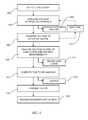
- FIG. 4is a flowchart outlining the steps in one embodiment of a method for estimating battery capacity in accordance with the present disclosure.
- FIG. 5is a flowchart outlining the steps in another embodiment of a method for estimating battery capacity in accordance with the present disclosure.
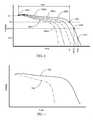
- FIG. 6is a graph providing multiple statistically-derived battery load curves showing voltage versus time for a given battery under various load conditions.
- FIG. 7is a graph showing minimum and maximum statistically-derived battery load curves showing voltage versus time for a given battery under minimum and maximum presumed loads.
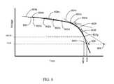
- FIG. 8is a high-resolution portion of one of the graphs of FIG. 6 , showing a series of linear fit approximations of the curve based on voltage measurements.
- implantablemeans a device that can be completely implanted into a human or animal body, with no portions of the apparatus extending outside the body after implantation.
- implantable deviceand “implantable medical device” or “IMD” mean any type of electrical device that is implantable into a human or animal body, and is configured to monitor or affect a function of the body.
- implantable medical devicesinclude cardiac pacemakers, nerve stimulation devices, and implantable drug delivery devices.
- VNSvagus nerve stimulation
- the implant procedureis very similar to the implantation of a pacemaker.
- the generatoris implanted subcutaneously, typically in the upper left pectoral region.
- An electric leadis connected between the pulse generator and one or more electrodes that are attached to the vagus nerve. While the following description presents a system and method for estimating battery life in the context of an implantable vagus nerve stimulation system, this application is only exemplary. It is to be understood that the system and method disclosed herein can be applied to a wide variety of battery-powered electronic devices, and is not limited to the particular exemplary application in which it is shown and described.
- FIG. 1Shown in FIG. 1 is a schematic diagram of one embodiment of an implantable VNS system, indicated generally at 10 , implanted into a patient 12 .
- the systemincludes an implantable pulse generator (“IPG”) 14 , and lead 16 that includes one or more electrodes 18 located at the distal end of a tether.
- the tether and electrodes 18are collectively referred to as the lead 16 , and the lead provides an interface between the pulse generator 14 and the electrodes 18 .
- the electrodes 18are attachable to the vagus nerve 20 .
- An implantable VNS system of this type and having these basic featuresis known to those of skill in the art, and is commercially available, such as from Cyberonics, Inc. of Houston, Texas.
- the pulse generator 14can be a multi-programmable device, which allows a physician to set various parameters of operation of the device.
- the programmable parameterscan include signal amplitude (e.g., 0-3.5 mA), frequency (e.g., 1-30 Hz), pulse width (e.g., 130-1000 ⁇ s), signal ON time (e.g., 7-60 sec) and signal OFF time (e.g., 0.2-180 min). It is to be appreciated that these pulse parameters are only exemplary, and that other parameters can also be used.
- the pulsescan be delivered at the specified amplitude and frequency over the course of the ON time, and then during the OFF time, no stimulation takes place.
- pulse settingscan be 2 mA, at 15 Hz frequency, 250 ⁇ s pulse width, with a 30 sec ON time, and 5 min OFF time.
- the variability in parametersallows the physician to adjust for greater efficacy or less severe side effects, depending on the patient.
- the pulse generator 14can include within its housing a variety of components, including battery 22 , an antenna 24 , a GPS transceiver 26 , and a microprocessor 28 with digital memory.
- the battery 22can be a rechargeable battery, and can be configured for periodic inductive recharging. While the components of a recharging system are not specifically shown herein, an exemplary recharging system may include a recharging power source worn outside the patient's body, which includes a primary coil designed to inductively couple to a secondary coil implanted in the body and connected to battery 22 . Power is transferred from the primary coil to the secondary coil and stored in the battery 22 .
- Recharging sessionsmay occur daily, weekly, monthly, or some other frequency depending on the capacity of battery 22 and the rate of energy consumption of the electronics powered by battery 22 .
- the general concepts of a rechargeable battery 22 used in an implantable device 14are widely known but utilized infrequently because it is technically difficult to design and introduces more risks when patients fail to comply with the prescribed regimen for the recharging session.
- the antenna 24is a common element for an implantable device 14 , and can be provided to send and/or receive data and programming and control instructions from an external communications device, as discussed below. This allows the implanted device 14 to receive programming and control instructions from an external communications device, and to transmit data regarding operation of the pulse generation device. Communications and control with implanted devices is well known and widely used. Devices such as pacemakers and the like are routinely programmed and/or controlled via wireless communication methods, such as the Medical Information Communication System protocol (MICS), which uses radio waves to transmit information to and from implanted devices.
- MICSMedical Information Communication System protocol
- FIG. 3A more specific schematic diagram of the internal components of an embodiment of an implantable pulse generator device, indicated generally at 300 , is shown in FIG. 3 .
- the pulse generator deviceincludes a logic and control unit 302 , a voltage regulator unit 304 , an output unit 306 and a crystal oscillator 308 .
- the logic and control unit 302contains circuitry and programming for control and operation of the pulse generator device, along with digital memory for storing programming instructions.
- the logic and control unitis operatively coupled to an antenna 310 , which allows programming and operational data to be transmitted and received by the pulse generator device.
- the antenna 310is driven by the output unit 306 , which also directly provides nerve stimulation signals via the lead electrodes 312 .
- the crystal oscillator 308provides an accurate time signal for the logic and control unit 302 .
- the voltage regulator 304controls power input from the battery 314 to the logic and control unit.
- the pulse generatorcan also include a reed switch 316 that allows selective connection of the logic and control unit 302 or output unit 306 to ground 317 . This allows the pulse generator device 300 to operate in a secondary magnet mode, delivering a pre-programmed burst of stimulation when activated by an external magnet (e.g., a permanent magnet worn on the patient's wrist and swiped over switch 316 to activate the secondary mode of operation). While the elements shown in FIG. 3 are illustrated as hardware elements, it is to be recognized and understood that many portions of the pulse generator device can be implemented as firmware, software or the like, and that many combinations are possible.
- GPS transceiver26 in FIG. 2
- a GPS transceivercan be incorporated as a specific hardware element in the implanted pulse generation device 14
- GPS functionscan be programmed into the logic and control unit 302 .
- a GPS transceiver and/or corresponding programmingcan be placed in other locations associated with a patient's body.
- a GPS transceiver 50can be associated with an external PDA or smart phone-type device 52 , or a wristwatch or wristwatch-like device 54 , or some other external computing device.
- the wristwatch-like device 54can be considered as one example of a special purpose portable computing device.
- the external devicecan function as an activation or input/output device for the implanted device 14 .
- the external devicecan incorporate an output mechanism for providing indications to the user of aspects of operation of the implanted device 14 (e.g. operational parameters, errors, battery condition, responding to seizure detections, etc.).
- the output mechanismcan provide indications such as indicator lights, alphanumeric indications, icons, audible alerts, etc.
- the implanted device 14itself can also include an output mechanism in the form of an audible alert which can be heard outside the body. Such an alert can be useful for noting error conditions, battery depletion, etc.
- the smart phone 52 and wristwatch device 54are shown in FIG. 2 with antennas, which are intended to represent the wireless communications capability of the devices, rather than the shape or position of an actual antenna structure.
- the antennaallows the external device to receive signals from a cellular or other mobile telephone system, represented by the cellular tower 46 , or from satellites 48 , or other communications system.
- the external devicecan be configured to transmit data to the pulse generation device 14 using Bluetooth or some other wireless transmission protocol, for example.
- Performing various computational operations and/or having various hardware components included within a device other than the pulse generation device 14can be desirable for power conservation. For example, power-hungry microprocessing tasks and analysis can be transferred to the external device, rather than being performed by the microprocessor 28 of the pulse generation device 14 , with the results of those microprocessing tasks transmitted back to the implanted device 14 . This can conserve power for the implanted device 14 . Similarly, having an external GPS transceiver and associated microprocessor can also reduce power demands on the implanted pulse generator 14 . A GPS transceiver that is in substantially constant communication with a GPS satellite system and a microprocessor that analyzes the positional information can use significant power, which is at a premium with implanted devices.
- One microprocessing task that can be performed by an external device in communication with a battery powered deviceis computation of battery life or estimation of time to depletion or end of service of a battery.
- the microprocessor associated with a smart phone 52 or wristwatch device 54 or some other external devicecan be programmed to receive battery data measurements (e.g. open circuit voltage), transmitted from the pulse generator 14 , and perform the analysis to estimate remaining battery life.
- the external devicecan then transmit battery information, operational commands or other information to the pulse generation device 14 or some other device.
- a methodfor more accurately estimating battery capacity and time to battery depletion in an electronic device, such as an implanted pulse generator device like that shown in FIGS. 1-2 .
- the terminal voltage of a batterydepends upon several factors, such as the rate of change of chemical reactions in the battery, energy density variations, the rate of internal charge degradation, the rate of battery capacity loss, the rate of change of internal leakage, the state of charge for a given operating point, variation of internal resistance, load variation, rate of discharge, temperature variation, etc. While many of these factors are difficult to measure or compute directly and accurately, voltage can be directly measured with high accuracy.
- terminal voltageappears to be a good common denominator in relation to other relevant factors.
- the method disclosed hereinbased on the battery's voltage depletion rate (VDR) provides a simple implementation, and its estimation gets more accurate over time, especially in the last 25% of the battery's useable life threshold.
- the methodutilizes samples of battery voltage measurement and a lookup table of various voltage load curves. An appropriate load curve can be used for initial base line estimate only, after which direct voltage measurements are used to provide a linear extrapolation to battery depletion. As time passes, the battery voltage measurement determines the VDR of the battery over a given time period, with greater and greater accuracy.
- the first step in the methodis to select or establish a baseline VDR curve (step 400 ).
- This curveis a statistically-derived battery load curve of voltage versus time. This is a presumed curve, and is preferably a high confidence (+/ ⁇ 3-Sigma) curve which can be obtained from multiple data sets stored in a lookup table (e.g. in the external device).
- a lookup tablee.g. in the external device.
- the first approachis to extract load curves for all possible load scenarios (e.g., various VNS Therapies).
- curve 600 ais a curve showing voltage versus time for a relatively lightly loaded battery
- curve 600 erepresents the depletion of voltage over time for a higher load upon the battery.
- Curves 600 b - dshow load curves for other conditions between these two extremes.
- the load curves 600 a - e shown in FIG. 6can be computed based upon presumed battery loading conditions over time.
- the loading conditionscan include the resistance of the pulse generator lead (e.g. 3k Ohms), pulse current (e.g. 0.5-3.0 mA), pulse frequency (e.g. 15-30 Hz), pulse duration (e.g. 130-1000 ⁇ s), and duty cycle—that is, the percentage of time that pulses are generated (e.g. 10%, 33%, 50%).
- an applicable VDR load curvecan be computed. This curve can be stored in memory in the implanted device, and/or in an external device.
- a second approach to selecting or establishing a VDR load curveis to extract two boundary load curves, one for the minimum possible load and another for the maximum possible load (the best case and the worst case) that the system is expected ever to experience.
- This approachis illustrated in the graph of FIG. 7 , wherein a top boundary curve 700 is shown, corresponding to the minimum load condition, and a lower boundary curve 702 is shown, corresponding to the maximum load condition.
- the battery load for these minimum and maximum conditionscan be determined based upon anticipated or measured resistance, current, pulse frequency and duration, duty cycle and expected electronics power consumption of the implanted device, in the manner described above.
- Once the minimum and maximum curves 700 , 702 are determinedall operating load points that are between these two curves can be mathematically derived. Alternatively, a curve fitting or estimation operation can be used to derive the additional curves. For example, load points between the curves can be estimated based on the probability of points being near the median rather than the maximum or minimum.
- the next step in this methodis computation of the VDR during operation of the implanted device.
- battery terminal voltageis measured once per day, though other measurement periods can also be used (e.g., per second, per minute, per hour, etc.).
- Each voltage measurementcan be stored in memory (step 404 ), if desired. As noted above, it can be desirable to perform various computational operations using an external device, rather than the implanted device.
- the implanted devicecan transmit each voltage measurement to an external device (step 406 ) to allow that device to perform the battery capacity estimation. After transmission, the implanted device can simply wait some time “t” (step 416 ), depending upon the selected voltage measurement interval, before again measuring voltage at step 402 .
- each curve 600 a - erepresents the condition of the battery at its beginning of life (BOL).
- BOLbeginning of life
- the batterywill have some initial voltage, which can vary slightly from battery to battery, but is relatively predictable. In one embodiment, the BOL voltage is about 3.0 volt.
- the initial portion 604 of the voltage depletion curveis relatively linear, and only gradually diminishes until reaching a knee point 606 , at which the voltage begins to drop off.
- the initial, nearly linear portion 604 of the voltage curvecan represent anywhere from about 75% to about 90% of the battery's total life.
- the knee point 606can be referred to as the intensified follow-up indicator (IFI) point.
- the exact voltage point for this designationcan vary. In one embodiment, with a BOL voltage of 3.0 volt, the IFI voltage is about 2.74 volt, and the remaining battery capacity at this point is about 10%.
- a warning messagecan be displayed (e.g. on an external device) to a user to indicate that the battery of the implanted device has depleted to a level where more frequent clinical monitoring is recommended.
- the next point of interest in this embodimentis the near end of service (NEOS) point 608 .
- this pointcan represent a voltage of 2.41 volt, with about 5% of remaining battery capacity. Reaching the NEOS point can be viewed as indicating that the battery should be replaced as soon as possible. Again, an indication of NEOS can be provided to a user on an external device. Upon reaching the NEOS point, or at some voltage level thereafter, the implanted device can be programmed to discontinue full functioning, and revert to an energy saving mode, where only essential operations are undertaken to maintain memory, transmit data, or receive data, etc.
- the next point of interestis the end of service (EOS) point 610 , indicating that the battery's useful life is over (0% remaining capacity).
- EOSend of service
- a suitable EOS indicationcan be provided to an external device.
- the EOS point 610represents a voltage of about 2.0 volt. At this point, there is still some charge left in the battery, but the voltage level has become too low to maintain even basic functioning of the implanted device.
- the baseline VDR curve that was selected in step 400provides the first data point for estimating voltage depletion rate. This point is presumably the BOL point 602 in FIG. 6 .
- the first voltage measurementis taken (step 402 ) with the implanted device in operation, that measurement provides a second data point. Having this data allows the system to analyze the voltage in view of the VDR load curve and the measured voltage value (step 408 ). Specifically, using these two initial values, a linear extrapolation is made to predict the voltage depletion rate.
- the initial voltage depletion estimatemay have some error.
- the initial period of battery usecan demonstrate a slight increase in terminal voltage. If the first measured voltage value represents an increase from the initially-presumed voltage level, a linear extrapolation therefrom can appear to suggest that the battery will never die. However, once a second voltage measurement is taken, the initially presumed VDR curve is no longer needed. The load curve is required for the initial baseline estimate only. As time passes, the battery voltage measurement, rather than the curve selected in step 400 , determines the VDR of the battery. Future estimates are based solely on the measured battery terminal voltage data.
- step 408is regularly repeated throughout the life of the battery, but is implemented differently for the first voltage measurement than for all the rest.
- the battery lifeis estimated based upon the voltage in view of the selected VDR load curve. Thereafter, the battery life can be estimated, and the VDR curve updated, based solely on the first and subsequent measured voltage values.
- the VDR load curvecan be revised (step 410 ) based on the actual voltage measurements.
- the time to IFI, NEOS, EOS and time to rechargecan be estimated (step 412 ).
- This new battery life estimatecan be provided as output to a user (step 414 ) and transmitted back to the implanted device, such as an IPG (step 418 ) if desired.
- the systemcan then also record the new boundary and curve fit data (step 420 ). Output and indications to a user can be provided in a variety of ways.
- an external devicecan have an alphanumeric display (e.g. an LCD screen) that provides specific words or indications to a user, including icons indicating different battery conditions.
- an external devicecan have indicator lights or audio alerts that provide battery life indications.
- An audible alertcan also be provided by an implanted device itself. Other options can also be used.
- FIG. 8The process of using multiple voltage measurements to produce a linear fit is illustrated in FIG. 8 , which provides a high-resolution portion of one of the graphs of FIG. 6 .
- This graphshows a series of linear fit approximations, represented by straight line segments 804 a - f of the curve 800 based on voltage measurements. Over time, a series of voltage measurements 802 a - h are taken, and these fall in various places along the curve 800 .
- a linear approximationcan be made between any two voltage measurements, and these approximations gradually come closer and closer to predicting the NEOS, EOS, or time to recharge points, as shown. For example, while the linear extrapolation of line 804 d predicts an EOS time at time point 806 , line 804 e, computed subsequently, more accurately predicts EOS at time point 808 .
- boundary pointscan correspond to the IFI, NEOS and EOS points shown in FIG. 6 .
- the substantially linear portion 604 of the curvecan be referred to as “Fit-1,” and correspond to voltage in the range of 3.10V to 3.00V (i.e., between 602 and 606 ).
- the next linear fit boundarycan be called “Fit-2” and correspond to voltage in the range of 2.99V to 2.85V (i.e., between 606 and 608 ), and a final boundary “Fit-3” can correspond to voltage in the range of 2.85V to 2.00V (EOS) (i.e., between 608 and 610 ).
- region Fit-1can be fit or approximated by a mathematical model, but the shape of the curve changes significantly in the regions Fit-2 and Fit-3.
- the Fit-2 regioncan be fit with a second mathematical model and the Fit-3 region can be fit with a third mathematical model.
- Other pointscan also be predicted, if desired.
- the time required for the battery's terminal voltage to reach a given depleted valuecan be more accurately predicted.
- Some aspects of these methodscan require care and consideration during application. For example, it has been found that the accuracy of the battery life estimate can decline if the computation of the estimate is done within an hour of the effective change of the load and/or the load parameters. That is, if a physician changes operating parameters of the implanted device (e.g. through wireless transmission of new operating instructions to the implanted device), such as duty cycle, stimulation current, etc., a voltage measurement taken shortly after that sort of change can produce an inaccurate battery life estimate. However, such errors will gradually work themselves out with regular repeated voltage measurements in the subsequent days or weeks.
- the systemcan be programmed to select or establish a new VDR curve as a starting point whenever new operational parameters are initiated. That is, each time operational parameters are changed for the implanted device, the system can revert to step 400 in the process outlined in FIG. 4 , and begin as if the battery were at the beginning of its life.
- a new VDR curvecan be selected or established each time the battery is recharged.
- a rechargeable batterymay have a characteristic VDR curve, which can be analyzed using the methods disclosed herein.
- the method outlined in FIG. 4involves transmitting data, such as voltage measurements and battery life estimations, between an implanted device and an external device.
- datasuch as voltage measurements and battery life estimations
- all of the steps in the disclosed methodcan be performed by the implanted device, depending upon power availability and programming.
- the overall methodcan be viewed in a more simplified way, as depicted in FIG. 5 .
- FIG. 5Provided in FIG. 5 is a flowchart outlining the steps in a simplified embodiment of a method for estimating battery capacity in accordance with the present disclosure.
- the first stepis to select or establish an appropriate load curve (step 500 ), and can be done in the manner discussed above.
- the systemrepeatedly measures battery terminal voltage at regular intervals (step 502 ).
- the systemlinearizes and extends the load curve (step 504 ) in the manner outlined above, and computes the battery life parameters, such as time to IFI, NEOS, EOS and time to recharge (step 506 ). Finally, the system provides output of some kind to a user (step 508 ), indicating the battery life estimate, and records desired data, such as the voltage measurements, modified VDR curve, battery life estimates, etc.
- output to a usercan be in the form of an audible indication from the implanted device.
- the method disclosed hereinprovides a simple and accurate battery useable time estimation.
- the accuracy of the time estimationincreases over time for a given operating load or operational regime. No additional hardware is required to implement this method.
- this methodallows battery energy to be used to the greatest extent possible, providing longer operating time or time between surgical operations to replace or service in implanted device.
- This methodis accurate and independent of battery capacity, operating environment, load behavior, and dynamic and or static loads, etc. The method is independent because it does not need as many inputs as other battery estimation methods and adapts to changes during operation of the device.
Landscapes
- Physics & Mathematics (AREA)
- General Physics & Mathematics (AREA)
- Health & Medical Sciences (AREA)
- Engineering & Computer Science (AREA)
- Biomedical Technology (AREA)
- Nuclear Medicine, Radiotherapy & Molecular Imaging (AREA)
- Radiology & Medical Imaging (AREA)
- Life Sciences & Earth Sciences (AREA)
- Animal Behavior & Ethology (AREA)
- General Health & Medical Sciences (AREA)
- Public Health (AREA)
- Veterinary Medicine (AREA)
- Charge And Discharge Circuits For Batteries Or The Like (AREA)
Abstract
Description
Claims (22)
Priority Applications (3)
| Application Number | Priority Date | Filing Date | Title |
|---|---|---|---|
| US13/098,141US8761885B2 (en) | 2011-04-29 | 2011-04-29 | Battery life estimation based on voltage depletion rate |
| EP11797061.6AEP2701799B1 (en) | 2011-04-29 | 2011-11-16 | Battery life estimation based on voltage depletion rate |
| PCT/US2011/061003WO2012148466A1 (en) | 2011-04-29 | 2011-11-16 | Battery life estimation based on voltage depletion rate |
Applications Claiming Priority (1)
| Application Number | Priority Date | Filing Date | Title |
|---|---|---|---|
| US13/098,141US8761885B2 (en) | 2011-04-29 | 2011-04-29 | Battery life estimation based on voltage depletion rate |
Publications (2)
| Publication Number | Publication Date |
|---|---|
| US20120277832A1 US20120277832A1 (en) | 2012-11-01 |
| US8761885B2true US8761885B2 (en) | 2014-06-24 |
Family
ID=45349557
Family Applications (1)
| Application Number | Title | Priority Date | Filing Date |
|---|---|---|---|
| US13/098,141Active2031-07-28US8761885B2 (en) | 2011-04-29 | 2011-04-29 | Battery life estimation based on voltage depletion rate |
Country Status (3)
| Country | Link |
|---|---|
| US (1) | US8761885B2 (en) |
| EP (1) | EP2701799B1 (en) |
| WO (1) | WO2012148466A1 (en) |
Cited By (3)
| Publication number | Priority date | Publication date | Assignee | Title |
|---|---|---|---|---|
| US20130175996A1 (en)* | 2012-01-05 | 2013-07-11 | IDesign, Inc | Characterizing battery discharge under different loads |
| US20180152025A1 (en)* | 2014-01-16 | 2018-05-31 | Boston Scientific Neuromodulation Corporation | Determining and Forecasting End of Life for an Implantable Medical Device Having a Rechargeable Battery |
| US11730966B2 (en)* | 2019-07-03 | 2023-08-22 | Pacesetter, Inc. | Methods, systems, and devices that estimate remaining longevity of an implanted medical device with improved accuracy |
Families Citing this family (19)
| Publication number | Priority date | Publication date | Assignee | Title |
|---|---|---|---|---|
| US9551758B2 (en) | 2012-12-27 | 2017-01-24 | Duracell U.S. Operations, Inc. | Remote sensing of remaining battery capacity using on-battery circuitry |
| US9478850B2 (en) | 2013-05-23 | 2016-10-25 | Duracell U.S. Operations, Inc. | Omni-directional antenna for a cylindrical body |
| US9327135B2 (en) | 2013-06-04 | 2016-05-03 | Boston Scientific Neuromodulation Corporation | External device for determining an optimal implantable medical device for a patient using information determined during an external trial stimulation phase |
| US9726763B2 (en) | 2013-06-21 | 2017-08-08 | Duracell U.S. Operations, Inc. | Systems and methods for remotely determining a battery characteristic |
| JP6094469B2 (en)* | 2013-12-25 | 2017-03-15 | トヨタ自動車株式会社 | Power control device |
| EP3094983A1 (en) | 2014-01-14 | 2016-11-23 | Fresenius Vial SAS | Method and device for determining the remaining run time of a battery |
| US9882250B2 (en) | 2014-05-30 | 2018-01-30 | Duracell U.S. Operations, Inc. | Indicator circuit decoupled from a ground plane |
| US9625515B2 (en)* | 2014-06-09 | 2017-04-18 | Communications & Power Industries Llc | Predicting the end of service life for a vacuum electron device |
| US10297875B2 (en) | 2015-09-01 | 2019-05-21 | Duracell U.S. Operations, Inc. | Battery including an on-cell indicator |
| CN106443454A (en)* | 2016-07-07 | 2017-02-22 | 惠州市博惠大科技有限公司 | Real-time monitoring and recognition method and system of lifetime of automobile battery |
| US11191027B2 (en)* | 2016-10-11 | 2021-11-30 | Sony Group Corporation | Automatic power saving selection based on target use |
| US10483634B2 (en) | 2016-11-01 | 2019-11-19 | Duracell U.S. Operations, Inc. | Positive battery terminal antenna ground plane |
| US10608293B2 (en) | 2016-11-01 | 2020-03-31 | Duracell U.S. Operations, Inc. | Dual sided reusable battery indicator |
| US10151802B2 (en) | 2016-11-01 | 2018-12-11 | Duracell U.S. Operations, Inc. | Reusable battery indicator with electrical lock and key |
| US11024891B2 (en) | 2016-11-01 | 2021-06-01 | Duracell U.S. Operations, Inc. | Reusable battery indicator with lock and key mechanism |
| US10818979B2 (en) | 2016-11-01 | 2020-10-27 | Duracell U.S. Operations, Inc. | Single sided reusable battery indicator |
| CN110807563B (en)* | 2020-01-07 | 2020-06-05 | 广东招才通信息科技有限公司 | Big data-based equipment life prediction system and method |
| US20230420959A1 (en)* | 2020-11-18 | 2023-12-28 | Cochlear Limited | Implantable battery disconnection |
| US11837754B2 (en) | 2020-12-30 | 2023-12-05 | Duracell U.S. Operations, Inc. | Magnetic battery cell connection mechanism |
Citations (104)
| Publication number | Priority date | Publication date | Assignee | Title |
|---|---|---|---|---|
| US3796221A (en) | 1971-07-07 | 1974-03-12 | N Hagfors | Apparatus for delivering electrical stimulation energy to body-implanted apparatus with signal-receiving means |
| US4324251A (en) | 1980-06-10 | 1982-04-13 | Pacesetter Systems, Inc. | Battery monitoring means and method for an implantable tissue stimulator |
| US4488555A (en) | 1982-12-13 | 1984-12-18 | Mieczyslaw Mirowski | Battery condition warning system for medical implant |
| US4556061A (en) | 1982-08-18 | 1985-12-03 | Cordis Corporation | Cardiac pacer with battery consumption monitor circuit |
| US4686990A (en) | 1985-10-02 | 1987-08-18 | Siemens Aktiengesellschaft | Battery test circuit for a heart pacemaker |
| US4702254A (en) | 1983-09-14 | 1987-10-27 | Jacob Zabara | Neurocybernetic prosthesis |
| US4715381A (en) | 1985-10-02 | 1987-12-29 | Siemens Aktiengesellschaft | Battery test circuit for a heart pacemaker |
| US4850356A (en) | 1980-08-08 | 1989-07-25 | Darox Corporation | Defibrillator electrode system |
| US4867164A (en) | 1983-09-14 | 1989-09-19 | Jacob Zabara | Neurocybernetic prosthesis |
| US4899750A (en) | 1988-04-19 | 1990-02-13 | Siemens-Pacesetter, Inc. | Lead impedance scanning system for pacemakers |
| US4964407A (en) | 1988-08-29 | 1990-10-23 | Intermedics, Inc. | Method and apparatus for assuring pacer programming is compatible with the lead |
| US5025807A (en) | 1983-09-14 | 1991-06-25 | Jacob Zabara | Neurocybernetic prosthesis |
| US5127404A (en) | 1990-01-22 | 1992-07-07 | Medtronic, Inc. | Telemetry format for implanted medical device |
| US5137021A (en) | 1990-11-29 | 1992-08-11 | Medtronic, Inc. | Lead current measurement circuit |
| US5137020A (en) | 1990-11-29 | 1992-08-11 | Medtronic, Inc. | Battery impedance measurement apparatus |
| US5146920A (en) | 1989-11-20 | 1992-09-15 | Sanyo Electric Co., Ltd. | Wireless low-frequency medical treatment device with pulse interruption based upon electrode contact with the body |
| US5154172A (en) | 1989-11-13 | 1992-10-13 | Cyberonics, Inc. | Constant current sources with programmable voltage source |
| US5179950A (en) | 1989-11-13 | 1993-01-19 | Cyberonics, Inc. | Implanted apparatus having micro processor controlled current and voltage sources with reduced voltage levels when not providing stimulation |
| US5188104A (en) | 1991-02-01 | 1993-02-23 | Cyberonics, Inc. | Treatment of eating disorders by nerve stimulation |
| US5193538A (en) | 1989-02-14 | 1993-03-16 | Siemens Aktiengesellschaft | In vivo implantable medical device with battery monitoring circuitry |
| US5201865A (en) | 1991-10-28 | 1993-04-13 | Medtronic, Inc. | Medical lead impedance measurement system |
| US5201808A (en) | 1992-02-10 | 1993-04-13 | Telectronics Pacing Systems, Inc. | Minute volume rate-responsive pacemaker employing impedance sensing on a unipolar lead |
| US5215086A (en) | 1991-05-03 | 1993-06-01 | Cyberonics, Inc. | Therapeutic treatment of migraine symptoms by stimulation |
| US5222494A (en) | 1991-07-31 | 1993-06-29 | Cyberonics, Inc. | Implantable tissue stimulator output stabilization system |
| US5231988A (en) | 1991-08-09 | 1993-08-03 | Cyberonics, Inc. | Treatment of endocrine disorders by nerve stimulation |
| US5263480A (en) | 1991-02-01 | 1993-11-23 | Cyberonics, Inc. | Treatment of eating disorders by nerve stimulation |
| US5269303A (en) | 1991-02-22 | 1993-12-14 | Cyberonics, Inc. | Treatment of dementia by nerve stimulation |
| US5299569A (en) | 1991-05-03 | 1994-04-05 | Cyberonics, Inc. | Treatment of neuropsychiatric disorders by nerve stimulation |
| US5330515A (en) | 1992-06-17 | 1994-07-19 | Cyberonics, Inc. | Treatment of pain by vagal afferent stimulation |
| US5335657A (en) | 1991-05-03 | 1994-08-09 | Cyberonics, Inc. | Therapeutic treatment of sleep disorder by nerve stimulation |
| US5352968A (en) | 1992-05-28 | 1994-10-04 | Apple Computer, Inc. | Battery charge state determination |
| US5372607A (en) | 1993-06-23 | 1994-12-13 | Medtronic, Inc. | Method and apparatus for monitoring pacemaker intervals |
| US5391193A (en)* | 1993-02-05 | 1995-02-21 | Medtronic, Inc. | Method and apparatus for battery depletion monitoring |
| US5431692A (en) | 1993-08-02 | 1995-07-11 | Telectronics Pacing Systems, Inc. | Method and apparatus for testing compatibility of lead polarity and polarity programming of a cardiac stimulator |
| US5458624A (en) | 1993-10-06 | 1995-10-17 | Vitatron Medical, B.V. | Cardiac pacing system with improved end-of-life detector |
| US5496353A (en) | 1993-09-23 | 1996-03-05 | Grandjean; Pierre A. | End-of-life indication system for implantable pulse generator |
| US5507786A (en) | 1994-04-14 | 1996-04-16 | Pacesetter, Inc. | System and method for measuring and storing parametric data pertaining to operating characteristics of an implantable medical device |
| US5522865A (en) | 1989-09-22 | 1996-06-04 | Alfred E. Mann Foundation For Scientific Research | Voltage/current control system for a human tissue stimulator |
| US5534018A (en) | 1994-11-30 | 1996-07-09 | Medtronic, Inc. | Automatic lead recognition for implantable medical device |
| US5540730A (en) | 1995-06-06 | 1996-07-30 | Cyberonics, Inc. | Treatment of motility disorders by nerve stimulation |
| US5540734A (en) | 1994-09-28 | 1996-07-30 | Zabara; Jacob | Cranial nerve stimulation treatments using neurocybernetic prosthesis |
| US5549646A (en) | 1994-12-06 | 1996-08-27 | Pacesetter, Inc. | Periodic electrical lead intergrity testing system and method for implantable cardiac stimulating devices |
| US5571150A (en) | 1994-12-19 | 1996-11-05 | Cyberonics, Inc. | Treatment of patients in coma by nerve stimulation |
| US5620474A (en) | 1995-04-24 | 1997-04-15 | Vitatron Medical, B.V. | System and method for determining indicated pacemaker replacement time based upon battery impedance measurement |
| US5703469A (en) | 1995-06-05 | 1997-12-30 | Honda Giken Kogyo Kabushiki Kaisha | System for determining battery conditions |
| US5707400A (en) | 1995-09-19 | 1998-01-13 | Cyberonics, Inc. | Treating refractory hypertension by nerve stimulation |
| US5713936A (en) | 1995-11-08 | 1998-02-03 | Litronik Batterietechnologie Gmbh & Co. | Implantable medical device with end-of-life battery detection circuit |
| US5741307A (en) | 1997-01-21 | 1998-04-21 | Pacesetter, Inc. | Method for determining an ICD replacement time |
| US5741311A (en) | 1996-06-27 | 1998-04-21 | Medtronic, Inc. | Implantable medical device system with method for determining lead condition |
| US5744931A (en)* | 1995-09-01 | 1998-04-28 | Yazaki Corporation | Battery remaining capacity measuring apparatus |
| US5755742A (en) | 1996-11-05 | 1998-05-26 | Medtronic, Inc. | Cardioversion/defibrillation lead impedance measurement system |
| US5769873A (en) | 1996-10-15 | 1998-06-23 | Pacesetter, Inc. | Meter for measuring battery charge delivered in an implantable device |
| US5814088A (en) | 1997-03-26 | 1998-09-29 | Sulzer Intermedics Inc. | Cardiac stimulator with lead failure detector and warning system |
| US5876425A (en) | 1989-09-22 | 1999-03-02 | Advanced Bionics Corporation | Power control loop for implantable tissue stimulator |
| US5891179A (en) | 1997-11-20 | 1999-04-06 | Paceseter, Inc. | Method and apparatus for monitoring and displaying lead impedance in real-time for an implantable medical device |
| US5897577A (en) | 1997-11-07 | 1999-04-27 | Medtronic, Inc. | Pacing lead impedance monitoring circuit and method |
| US5928272A (en) | 1998-05-02 | 1999-07-27 | Cyberonics, Inc. | Automatic activation of a neurostimulator device using a detection algorithm based on cardiac activity |
| US6016448A (en) | 1998-10-27 | 2000-01-18 | Medtronic, Inc. | Multilevel ERI for implantable medical devices |
| US6073050A (en) | 1998-11-10 | 2000-06-06 | Advanced Bionics Corporation | Efficient integrated RF telemetry transmitter for use with implantable device |
| US6108579A (en) | 1996-04-15 | 2000-08-22 | Pacesetter, Inc. | Battery monitoring apparatus and method for programmers of cardiac stimulating devices |
| US6148235A (en) | 1998-07-17 | 2000-11-14 | Vitatron Medical, B.V. | Implantable stimulator with battery status measurement |
| US6167309A (en) | 1997-09-15 | 2000-12-26 | Cardiac Pacemakers, Inc. | Method for monitoring end of life for battery |
| US6181969B1 (en) | 1998-06-26 | 2001-01-30 | Advanced Bionics Corporation | Programmable current output stimulus stage for implantable device |
| US6185461B1 (en) | 1998-07-01 | 2001-02-06 | Pacesetter, Inc. | System and method for verification of recommended replacement time indication in an implantable cardiac stimulation device |
| US6212431B1 (en) | 1998-09-08 | 2001-04-03 | Advanced Bionics Corporation | Power transfer circuit for implanted devices |
| US6317633B1 (en) | 1999-01-19 | 2001-11-13 | Medtronic, Inc. | Implantable lead functional status monitor and method |
| US6341236B1 (en) | 1999-04-30 | 2002-01-22 | Ivan Osorio | Vagal nerve stimulation techniques for treatment of epileptic seizures |
| US20020013613A1 (en)* | 1999-07-07 | 2002-01-31 | Markus Haller | System and method for remote programming of an implantable medical device |
| US6400988B1 (en) | 2000-02-18 | 2002-06-04 | Pacesetter, Inc. | Implantable cardiac device having precision RRT indication |
| US6445951B1 (en) | 1999-10-12 | 2002-09-03 | Pacesetter, Inc. | Implantable cardiac stimulating device incorporating high frequency low amplitude lead impedance measurement |
| US6453198B1 (en) | 2000-04-28 | 2002-09-17 | Medtronic, Inc. | Power management for an implantable medical device |
| US6473644B1 (en) | 1999-10-13 | 2002-10-29 | Cyberonics, Inc. | Method to enhance cardiac capillary growth in heart failure patients |
| US6490484B2 (en) | 2001-01-24 | 2002-12-03 | Cardiac Pacemakers, Inc. | Apparatus and method for estimating battery condition in implantable cardioverter/defibrillators |
| US6490486B1 (en) | 2000-04-27 | 2002-12-03 | Pacesetter, Inc. | Implantable cardiac stimulation device and method that monitors displacement of an implanted lead |
| US20030065366A1 (en)* | 2001-10-02 | 2003-04-03 | Merritt Donald R. | System and method for determining remaining battery life for an implantable medical device |
| US6553263B1 (en) | 1999-07-30 | 2003-04-22 | Advanced Bionics Corporation | Implantable pulse generators using rechargeable zero-volt technology lithium-ion batteries |
| US6587719B1 (en) | 1999-07-01 | 2003-07-01 | Cyberonics, Inc. | Treatment of obesity by bilateral vagus nerve stimulation |
| US6609025B2 (en) | 2001-01-02 | 2003-08-19 | Cyberonics, Inc. | Treatment of obesity by bilateral sub-diaphragmatic nerve stimulation |
| US6622038B2 (en) | 2001-07-28 | 2003-09-16 | Cyberonics, Inc. | Treatment of movement disorders by near-diaphragmatic nerve stimulation |
| US6622047B2 (en) | 2001-07-28 | 2003-09-16 | Cyberonics, Inc. | Treatment of neuropsychiatric disorders by near-diaphragmatic nerve stimulation |
| US6622041B2 (en) | 2001-08-21 | 2003-09-16 | Cyberonics, Inc. | Treatment of congestive heart failure and autonomic cardiovascular drive disorders |
| US6620186B2 (en) | 2000-05-25 | 2003-09-16 | International Business Machines Corporation | Method and system for medical lead impedance test |
| US6631293B2 (en) | 1997-09-15 | 2003-10-07 | Cardiac Pacemakers, Inc. | Method for monitoring end of life for battery |
| US6648823B2 (en) | 2001-07-31 | 2003-11-18 | Medtronic, Inc. | Method and system of follow-up support for a medical device |
| US6658294B1 (en) | 2001-08-29 | 2003-12-02 | Pacesetter, Inc. | Implantable cardiac device having an impedance monitoring circuit and method |
| US6662053B2 (en) | 2000-08-17 | 2003-12-09 | William N. Borkan | Multichannel stimulator electronics and methods |
| US6687538B1 (en) | 2000-06-19 | 2004-02-03 | Medtronic, Inc. | Trial neuro stimulator with lead diagnostics |
| US6721600B2 (en) | 2000-01-19 | 2004-04-13 | Medtronic, Inc. | Implantable lead functional status monitor and method |
| US6745077B1 (en) | 2000-10-11 | 2004-06-01 | Advanced Bionics Corporation | Electronic impedance transformer for inductively-coupled load stabilization |
| US6748273B1 (en) | 1999-07-19 | 2004-06-08 | St. Jude Medical Ab | Method and circuit for determining the battery status in a medical implant |
| US6760625B1 (en) | 2001-10-11 | 2004-07-06 | Pacesetter, Inc. | Battery monitoring system for an implantable medical device |
| US6760624B2 (en) | 2001-12-03 | 2004-07-06 | Cardiac Pacemakers, Inc. | Method and apparatus for measuring lead impedance in an implantable cardiac rhythm management device |
| WO2004075982A1 (en) | 2003-02-21 | 2004-09-10 | Medtronic, Inc. | Implantable neurostimulator programming with battery longevity indication |
| US6820019B1 (en) | 1999-07-31 | 2004-11-16 | Medtronic, Inc. | Device and method for determining and communicating the remaining life of a battery in an implantable neurological tissue stimulating device |
| US6901293B2 (en) | 2003-04-07 | 2005-05-31 | Medtronic, Inc. | System and method for monitoring power source longevity of an implantable medical device |
| US6940255B2 (en) | 2003-10-23 | 2005-09-06 | Cardiac Pacemakers, Inc. | Battery charge indicator such as for an implantable medical device |
| US20060025829A1 (en)* | 2004-07-28 | 2006-02-02 | Armstrong Randolph K | Power supply monitoring for an implantable device |
| US20070150019A1 (en) | 2005-12-15 | 2007-06-28 | Cardiac Pacemakers, Inc | Implantable medical device powered by rechargeable battery |
| US20070179548A1 (en)* | 2006-01-27 | 2007-08-02 | Armstrong Randolph K | Power supply monitoring for an implantable device |
| US7254444B2 (en) | 2001-10-17 | 2007-08-07 | Encore Medical Asset Corporation | Electrical nerve stimulation device |
| US20070216366A1 (en) | 2006-03-15 | 2007-09-20 | Shoichi Inamine | Method for judging service life of primary battery |
| US20080097544A1 (en)* | 2006-10-20 | 2008-04-24 | Rajesh Krishan Gandhi | Dynamic battery management in an implantable device |
| US7904161B2 (en) | 2001-10-22 | 2011-03-08 | Oscor Inc. | Lead adaptor having low resistance conductors and/or encapsulated housing |
| US20120197341A1 (en)* | 2011-01-28 | 2012-08-02 | Cowley Anthony W | System and method for estimating battery capacity |
- 2011
- 2011-04-29USUS13/098,141patent/US8761885B2/enactiveActive
- 2011-11-16WOPCT/US2011/061003patent/WO2012148466A1/enactiveApplication Filing
- 2011-11-16EPEP11797061.6Apatent/EP2701799B1/enactiveActive
Patent Citations (114)
| Publication number | Priority date | Publication date | Assignee | Title |
|---|---|---|---|---|
| US3796221A (en) | 1971-07-07 | 1974-03-12 | N Hagfors | Apparatus for delivering electrical stimulation energy to body-implanted apparatus with signal-receiving means |
| US4324251A (en) | 1980-06-10 | 1982-04-13 | Pacesetter Systems, Inc. | Battery monitoring means and method for an implantable tissue stimulator |
| US4850356A (en) | 1980-08-08 | 1989-07-25 | Darox Corporation | Defibrillator electrode system |
| US4556061A (en) | 1982-08-18 | 1985-12-03 | Cordis Corporation | Cardiac pacer with battery consumption monitor circuit |
| US4488555A (en) | 1982-12-13 | 1984-12-18 | Mieczyslaw Mirowski | Battery condition warning system for medical implant |
| US4867164A (en) | 1983-09-14 | 1989-09-19 | Jacob Zabara | Neurocybernetic prosthesis |
| US4702254A (en) | 1983-09-14 | 1987-10-27 | Jacob Zabara | Neurocybernetic prosthesis |
| US5025807A (en) | 1983-09-14 | 1991-06-25 | Jacob Zabara | Neurocybernetic prosthesis |
| US4686990A (en) | 1985-10-02 | 1987-08-18 | Siemens Aktiengesellschaft | Battery test circuit for a heart pacemaker |
| US4715381A (en) | 1985-10-02 | 1987-12-29 | Siemens Aktiengesellschaft | Battery test circuit for a heart pacemaker |
| US4899750A (en) | 1988-04-19 | 1990-02-13 | Siemens-Pacesetter, Inc. | Lead impedance scanning system for pacemakers |
| US4964407A (en) | 1988-08-29 | 1990-10-23 | Intermedics, Inc. | Method and apparatus for assuring pacer programming is compatible with the lead |
| US5193538A (en) | 1989-02-14 | 1993-03-16 | Siemens Aktiengesellschaft | In vivo implantable medical device with battery monitoring circuitry |
| US5522865A (en) | 1989-09-22 | 1996-06-04 | Alfred E. Mann Foundation For Scientific Research | Voltage/current control system for a human tissue stimulator |
| US5876425A (en) | 1989-09-22 | 1999-03-02 | Advanced Bionics Corporation | Power control loop for implantable tissue stimulator |
| US5154172A (en) | 1989-11-13 | 1992-10-13 | Cyberonics, Inc. | Constant current sources with programmable voltage source |
| US5179950A (en) | 1989-11-13 | 1993-01-19 | Cyberonics, Inc. | Implanted apparatus having micro processor controlled current and voltage sources with reduced voltage levels when not providing stimulation |
| US5146920A (en) | 1989-11-20 | 1992-09-15 | Sanyo Electric Co., Ltd. | Wireless low-frequency medical treatment device with pulse interruption based upon electrode contact with the body |
| US5127404A (en) | 1990-01-22 | 1992-07-07 | Medtronic, Inc. | Telemetry format for implanted medical device |
| US5344431A (en) | 1990-01-22 | 1994-09-06 | Medtronic, Inc. | Method and apparatus for determination of end-of-service for implantable devices |
| US5137020A (en) | 1990-11-29 | 1992-08-11 | Medtronic, Inc. | Battery impedance measurement apparatus |
| US5137021A (en) | 1990-11-29 | 1992-08-11 | Medtronic, Inc. | Lead current measurement circuit |
| US5188104A (en) | 1991-02-01 | 1993-02-23 | Cyberonics, Inc. | Treatment of eating disorders by nerve stimulation |
| US5263480A (en) | 1991-02-01 | 1993-11-23 | Cyberonics, Inc. | Treatment of eating disorders by nerve stimulation |
| US5269303A (en) | 1991-02-22 | 1993-12-14 | Cyberonics, Inc. | Treatment of dementia by nerve stimulation |
| US5335657A (en) | 1991-05-03 | 1994-08-09 | Cyberonics, Inc. | Therapeutic treatment of sleep disorder by nerve stimulation |
| US5215086A (en) | 1991-05-03 | 1993-06-01 | Cyberonics, Inc. | Therapeutic treatment of migraine symptoms by stimulation |
| US5299569A (en) | 1991-05-03 | 1994-04-05 | Cyberonics, Inc. | Treatment of neuropsychiatric disorders by nerve stimulation |
| US5222494A (en) | 1991-07-31 | 1993-06-29 | Cyberonics, Inc. | Implantable tissue stimulator output stabilization system |
| US5231988A (en) | 1991-08-09 | 1993-08-03 | Cyberonics, Inc. | Treatment of endocrine disorders by nerve stimulation |
| US5201865A (en) | 1991-10-28 | 1993-04-13 | Medtronic, Inc. | Medical lead impedance measurement system |
| US5201808A (en) | 1992-02-10 | 1993-04-13 | Telectronics Pacing Systems, Inc. | Minute volume rate-responsive pacemaker employing impedance sensing on a unipolar lead |
| US5352968A (en) | 1992-05-28 | 1994-10-04 | Apple Computer, Inc. | Battery charge state determination |
| US5330515A (en) | 1992-06-17 | 1994-07-19 | Cyberonics, Inc. | Treatment of pain by vagal afferent stimulation |
| US5391193A (en)* | 1993-02-05 | 1995-02-21 | Medtronic, Inc. | Method and apparatus for battery depletion monitoring |
| US5372607A (en) | 1993-06-23 | 1994-12-13 | Medtronic, Inc. | Method and apparatus for monitoring pacemaker intervals |
| US5431692A (en) | 1993-08-02 | 1995-07-11 | Telectronics Pacing Systems, Inc. | Method and apparatus for testing compatibility of lead polarity and polarity programming of a cardiac stimulator |
| US5496353A (en) | 1993-09-23 | 1996-03-05 | Grandjean; Pierre A. | End-of-life indication system for implantable pulse generator |
| US5458624A (en) | 1993-10-06 | 1995-10-17 | Vitatron Medical, B.V. | Cardiac pacing system with improved end-of-life detector |
| US5507786A (en) | 1994-04-14 | 1996-04-16 | Pacesetter, Inc. | System and method for measuring and storing parametric data pertaining to operating characteristics of an implantable medical device |
| US5540734A (en) | 1994-09-28 | 1996-07-30 | Zabara; Jacob | Cranial nerve stimulation treatments using neurocybernetic prosthesis |
| US5534018A (en) | 1994-11-30 | 1996-07-09 | Medtronic, Inc. | Automatic lead recognition for implantable medical device |
| US5549646A (en) | 1994-12-06 | 1996-08-27 | Pacesetter, Inc. | Periodic electrical lead intergrity testing system and method for implantable cardiac stimulating devices |
| US5571150A (en) | 1994-12-19 | 1996-11-05 | Cyberonics, Inc. | Treatment of patients in coma by nerve stimulation |
| US5620474A (en) | 1995-04-24 | 1997-04-15 | Vitatron Medical, B.V. | System and method for determining indicated pacemaker replacement time based upon battery impedance measurement |
| US5703469A (en) | 1995-06-05 | 1997-12-30 | Honda Giken Kogyo Kabushiki Kaisha | System for determining battery conditions |
| US5540730A (en) | 1995-06-06 | 1996-07-30 | Cyberonics, Inc. | Treatment of motility disorders by nerve stimulation |
| US5744931A (en)* | 1995-09-01 | 1998-04-28 | Yazaki Corporation | Battery remaining capacity measuring apparatus |
| US5707400A (en) | 1995-09-19 | 1998-01-13 | Cyberonics, Inc. | Treating refractory hypertension by nerve stimulation |
| US5713936A (en) | 1995-11-08 | 1998-02-03 | Litronik Batterietechnologie Gmbh & Co. | Implantable medical device with end-of-life battery detection circuit |
| US6108579A (en) | 1996-04-15 | 2000-08-22 | Pacesetter, Inc. | Battery monitoring apparatus and method for programmers of cardiac stimulating devices |
| US5741311A (en) | 1996-06-27 | 1998-04-21 | Medtronic, Inc. | Implantable medical device system with method for determining lead condition |
| US5769873A (en) | 1996-10-15 | 1998-06-23 | Pacesetter, Inc. | Meter for measuring battery charge delivered in an implantable device |
| US5755742A (en) | 1996-11-05 | 1998-05-26 | Medtronic, Inc. | Cardioversion/defibrillation lead impedance measurement system |
| US5741307A (en) | 1997-01-21 | 1998-04-21 | Pacesetter, Inc. | Method for determining an ICD replacement time |
| US5925068A (en) | 1997-01-21 | 1999-07-20 | Pacesetter, Inc. | Method for determining an ICD replacment time |
| US5814088A (en) | 1997-03-26 | 1998-09-29 | Sulzer Intermedics Inc. | Cardiac stimulator with lead failure detector and warning system |
| US6654640B2 (en) | 1997-09-15 | 2003-11-25 | Cardiac Pacemakers, Inc. | Method for monitoring end of life for battery |
| US6631293B2 (en) | 1997-09-15 | 2003-10-07 | Cardiac Pacemakers, Inc. | Method for monitoring end of life for battery |
| US6167309A (en) | 1997-09-15 | 2000-12-26 | Cardiac Pacemakers, Inc. | Method for monitoring end of life for battery |
| US5897577A (en) | 1997-11-07 | 1999-04-27 | Medtronic, Inc. | Pacing lead impedance monitoring circuit and method |
| US5891179A (en) | 1997-11-20 | 1999-04-06 | Paceseter, Inc. | Method and apparatus for monitoring and displaying lead impedance in real-time for an implantable medical device |
| US5928272A (en) | 1998-05-02 | 1999-07-27 | Cyberonics, Inc. | Automatic activation of a neurostimulator device using a detection algorithm based on cardiac activity |
| US6181969B1 (en) | 1998-06-26 | 2001-01-30 | Advanced Bionics Corporation | Programmable current output stimulus stage for implantable device |
| US6185461B1 (en) | 1998-07-01 | 2001-02-06 | Pacesetter, Inc. | System and method for verification of recommended replacement time indication in an implantable cardiac stimulation device |
| US6148235A (en) | 1998-07-17 | 2000-11-14 | Vitatron Medical, B.V. | Implantable stimulator with battery status measurement |
| US6212431B1 (en) | 1998-09-08 | 2001-04-03 | Advanced Bionics Corporation | Power transfer circuit for implanted devices |
| US6016448A (en) | 1998-10-27 | 2000-01-18 | Medtronic, Inc. | Multilevel ERI for implantable medical devices |
| US6073050A (en) | 1998-11-10 | 2000-06-06 | Advanced Bionics Corporation | Efficient integrated RF telemetry transmitter for use with implantable device |
| US6317633B1 (en) | 1999-01-19 | 2001-11-13 | Medtronic, Inc. | Implantable lead functional status monitor and method |
| US6587727B2 (en) | 1999-04-30 | 2003-07-01 | Ivan Osorio | Vagal nerve stimulation techniques for treatment of epileptic seizures |
| US6671556B2 (en) | 1999-04-30 | 2003-12-30 | Ivan Osorio | Vagal nerve stimulation techniques for treatment of epileptic seizures |
| US6341236B1 (en) | 1999-04-30 | 2002-01-22 | Ivan Osorio | Vagal nerve stimulation techniques for treatment of epileptic seizures |
| US6587719B1 (en) | 1999-07-01 | 2003-07-01 | Cyberonics, Inc. | Treatment of obesity by bilateral vagus nerve stimulation |
| US20020013613A1 (en)* | 1999-07-07 | 2002-01-31 | Markus Haller | System and method for remote programming of an implantable medical device |
| US6748273B1 (en) | 1999-07-19 | 2004-06-08 | St. Jude Medical Ab | Method and circuit for determining the battery status in a medical implant |
| US6553263B1 (en) | 1999-07-30 | 2003-04-22 | Advanced Bionics Corporation | Implantable pulse generators using rechargeable zero-volt technology lithium-ion batteries |
| US6820019B1 (en) | 1999-07-31 | 2004-11-16 | Medtronic, Inc. | Device and method for determining and communicating the remaining life of a battery in an implantable neurological tissue stimulating device |
| US6445951B1 (en) | 1999-10-12 | 2002-09-03 | Pacesetter, Inc. | Implantable cardiac stimulating device incorporating high frequency low amplitude lead impedance measurement |
| US6473644B1 (en) | 1999-10-13 | 2002-10-29 | Cyberonics, Inc. | Method to enhance cardiac capillary growth in heart failure patients |
| US6721600B2 (en) | 2000-01-19 | 2004-04-13 | Medtronic, Inc. | Implantable lead functional status monitor and method |
| US6400988B1 (en) | 2000-02-18 | 2002-06-04 | Pacesetter, Inc. | Implantable cardiac device having precision RRT indication |
| US6490486B1 (en) | 2000-04-27 | 2002-12-03 | Pacesetter, Inc. | Implantable cardiac stimulation device and method that monitors displacement of an implanted lead |
| US6453198B1 (en) | 2000-04-28 | 2002-09-17 | Medtronic, Inc. | Power management for an implantable medical device |
| US6620186B2 (en) | 2000-05-25 | 2003-09-16 | International Business Machines Corporation | Method and system for medical lead impedance test |
| US6687538B1 (en) | 2000-06-19 | 2004-02-03 | Medtronic, Inc. | Trial neuro stimulator with lead diagnostics |
| US6662053B2 (en) | 2000-08-17 | 2003-12-09 | William N. Borkan | Multichannel stimulator electronics and methods |
| US6745077B1 (en) | 2000-10-11 | 2004-06-01 | Advanced Bionics Corporation | Electronic impedance transformer for inductively-coupled load stabilization |
| US6609025B2 (en) | 2001-01-02 | 2003-08-19 | Cyberonics, Inc. | Treatment of obesity by bilateral sub-diaphragmatic nerve stimulation |
| US6490484B2 (en) | 2001-01-24 | 2002-12-03 | Cardiac Pacemakers, Inc. | Apparatus and method for estimating battery condition in implantable cardioverter/defibrillators |
| US6622047B2 (en) | 2001-07-28 | 2003-09-16 | Cyberonics, Inc. | Treatment of neuropsychiatric disorders by near-diaphragmatic nerve stimulation |
| US6622038B2 (en) | 2001-07-28 | 2003-09-16 | Cyberonics, Inc. | Treatment of movement disorders by near-diaphragmatic nerve stimulation |
| US6648823B2 (en) | 2001-07-31 | 2003-11-18 | Medtronic, Inc. | Method and system of follow-up support for a medical device |
| US6622041B2 (en) | 2001-08-21 | 2003-09-16 | Cyberonics, Inc. | Treatment of congestive heart failure and autonomic cardiovascular drive disorders |
| US6658294B1 (en) | 2001-08-29 | 2003-12-02 | Pacesetter, Inc. | Implantable cardiac device having an impedance monitoring circuit and method |
| US6671552B2 (en) | 2001-10-02 | 2003-12-30 | Medtronic, Inc. | System and method for determining remaining battery life for an implantable medical device |
| US20040039424A1 (en)* | 2001-10-02 | 2004-02-26 | Merritt Donald R. | System and method for determining remaining battery life for an implantable medical device |
| US20030065366A1 (en)* | 2001-10-02 | 2003-04-03 | Merritt Donald R. | System and method for determining remaining battery life for an implantable medical device |
| US6760625B1 (en) | 2001-10-11 | 2004-07-06 | Pacesetter, Inc. | Battery monitoring system for an implantable medical device |
| US6804557B1 (en) | 2001-10-11 | 2004-10-12 | Pacesetter, Inc. | Battery monitoring system for an implantable medical device |
| US7254444B2 (en) | 2001-10-17 | 2007-08-07 | Encore Medical Asset Corporation | Electrical nerve stimulation device |
| US7904161B2 (en) | 2001-10-22 | 2011-03-08 | Oscor Inc. | Lead adaptor having low resistance conductors and/or encapsulated housing |
| US6760624B2 (en) | 2001-12-03 | 2004-07-06 | Cardiac Pacemakers, Inc. | Method and apparatus for measuring lead impedance in an implantable cardiac rhythm management device |
| US7142923B2 (en) | 2003-02-21 | 2006-11-28 | Medtronic, Inc. | Implantable neurostimulator programming with battery longevity indication |
| WO2004075982A1 (en) | 2003-02-21 | 2004-09-10 | Medtronic, Inc. | Implantable neurostimulator programming with battery longevity indication |
| US6901293B2 (en) | 2003-04-07 | 2005-05-31 | Medtronic, Inc. | System and method for monitoring power source longevity of an implantable medical device |
| US6940255B2 (en) | 2003-10-23 | 2005-09-06 | Cardiac Pacemakers, Inc. | Battery charge indicator such as for an implantable medical device |
| US20060025829A1 (en)* | 2004-07-28 | 2006-02-02 | Armstrong Randolph K | Power supply monitoring for an implantable device |
| US7751891B2 (en) | 2004-07-28 | 2010-07-06 | Cyberonics, Inc. | Power supply monitoring for an implantable device |
| US20070150019A1 (en) | 2005-12-15 | 2007-06-28 | Cardiac Pacemakers, Inc | Implantable medical device powered by rechargeable battery |
| US20070179548A1 (en)* | 2006-01-27 | 2007-08-02 | Armstrong Randolph K | Power supply monitoring for an implantable device |
| US20070216366A1 (en) | 2006-03-15 | 2007-09-20 | Shoichi Inamine | Method for judging service life of primary battery |
| US20080097544A1 (en)* | 2006-10-20 | 2008-04-24 | Rajesh Krishan Gandhi | Dynamic battery management in an implantable device |
| US20120197341A1 (en)* | 2011-01-28 | 2012-08-02 | Cowley Anthony W | System and method for estimating battery capacity |
Non-Patent Citations (5)
| Title |
|---|
| International Application No. PCT/US2005/026514, Written Opinion dated Oct. 10, 2006, 4 pgs. |
| International Application No. PCT/US2007/000337, Written Opinion dated Jul. 27, 2008, 8 pgs. |
| International Patent Application No. PCT/US2011/061003, International Search Report and Written Opinion dated Jun. 28, 2012, 10 pages. |
| Terry, R.S., et al., "The Implantable Neurocybernetic Prosthesis System," Pacing and Clinical Electrophysiology, vol. 14, No. 1, (Jan. 1991), pp. 86-93. |
| Woodbury, J.W. et al., "Vagal Stimulation Reduces the Severity of Maximal Electroshock Seizures in Intact Rats: Use of Cuff Electrode for Stimulating and Recording," PACE, vol. 14, (Jan. 1991), pp. 94-107. |
Cited By (4)
| Publication number | Priority date | Publication date | Assignee | Title |
|---|---|---|---|---|
| US20130175996A1 (en)* | 2012-01-05 | 2013-07-11 | IDesign, Inc | Characterizing battery discharge under different loads |
| US20180152025A1 (en)* | 2014-01-16 | 2018-05-31 | Boston Scientific Neuromodulation Corporation | Determining and Forecasting End of Life for an Implantable Medical Device Having a Rechargeable Battery |
| US10806930B2 (en)* | 2014-01-16 | 2020-10-20 | Boston Scientific Neuromodulation Corporation | Determining and forecasting end of life for an implantable medical device having a rechargeable battery |
| US11730966B2 (en)* | 2019-07-03 | 2023-08-22 | Pacesetter, Inc. | Methods, systems, and devices that estimate remaining longevity of an implanted medical device with improved accuracy |
Also Published As
| Publication number | Publication date |
|---|---|
| EP2701799B1 (en) | 2016-03-30 |
| US20120277832A1 (en) | 2012-11-01 |
| EP2701799A1 (en) | 2014-03-05 |
| WO2012148466A1 (en) | 2012-11-01 |
Similar Documents
| Publication | Publication Date | Title |
|---|---|---|
| US8761885B2 (en) | Battery life estimation based on voltage depletion rate | |
| US8577459B2 (en) | System and method for estimating battery capacity | |
| US6671552B2 (en) | System and method for determining remaining battery life for an implantable medical device | |
| EP1784239B1 (en) | Power supply monitoring for an implantable device | |
| US8639338B2 (en) | System and method for monitoring power source longevity of an implantable medical device | |
| US8565881B2 (en) | Power supply monitoring for an implantable device | |
| US8718771B2 (en) | Dynamic battery management in an implantable device | |
| US10806930B2 (en) | Determining and forecasting end of life for an implantable medical device having a rechargeable battery | |
| US20120109248A1 (en) | Battery discharge measurement device and method | |
| US20140278168A1 (en) | Elective replacement indication generation | |
| WO2008089375A1 (en) | Methods for estimating remaining battery service life in an implantable medical device | |
| US11730966B2 (en) | Methods, systems, and devices that estimate remaining longevity of an implanted medical device with improved accuracy | |
| US8996113B2 (en) | Recommended replacement time based on user selection | |
| US20250242165A1 (en) | Systems and methods for determining a predicted device run time in implanted medical devices | |
| US20250242166A1 (en) | Recharge interval for medical device | |
| WO2025049786A1 (en) | Battery status determination | |
| WO2024127132A1 (en) | State-of-health for a rechargeable battery | |
| EP1784240A2 (en) | Impedance measurement for an implantable device |
Legal Events
| Date | Code | Title | Description |
|---|---|---|---|
| AS | Assignment | Owner name:CYBERONICS INC., TEXAS Free format text:ASSIGNMENT OF ASSIGNORS INTEREST;ASSIGNOR:HUSSAIN, SAADAT;REEL/FRAME:026475/0833 Effective date:20110514 | |
| STCF | Information on status: patent grant | Free format text:PATENTED CASE | |
| MAFP | Maintenance fee payment | Free format text:PAYMENT OF MAINTENANCE FEE, 4TH YEAR, LARGE ENTITY (ORIGINAL EVENT CODE: M1551) Year of fee payment:4 | |
| AS | Assignment | Owner name:ARES CAPITAL CORPORATION, AS COLLATERAL AGENT, NEW YORK Free format text:PATENT SECURITY AGREEMENT;ASSIGNOR:LIVANOVA USA, INC.;REEL/FRAME:053673/0675 Effective date:20200617 | |
| AS | Assignment | Owner name:LIVANOVA USA, INC., TEXAS Free format text:CHANGE OF NAME;ASSIGNOR:CYBERONICS, INC.;REEL/FRAME:053306/0229 Effective date:20170630 | |
| AS | Assignment | Owner name:ACF FINCO I LP, AS COLLATERAL AGENT, NEW YORK Free format text:PATENT SECURITY AGREEMENT;ASSIGNOR:LIVANOVA USA, INC.;REEL/FRAME:054881/0784 Effective date:20201230 | |
| AS | Assignment | Owner name:LIVANOVA USA, INC., TEXAS Free format text:RELEASE BY SECURED PARTY;ASSIGNOR:ARES CAPITAL CORPORATION, AS AGENT FOR THE LENDERS;REEL/FRAME:057189/0001 Effective date:20210812 Owner name:GOLDMAN SACHS BANK USA, AS COLLATERAL AGENT, NEW YORK Free format text:SECURITY INTEREST;ASSIGNOR:LIVANOVA USA, INC.;REEL/FRAME:057188/0001 Effective date:20210813 | |
| AS | Assignment | Owner name:LIVANOVA USA, INC., TEXAS Free format text:RELEASE BY SECURED PARTY;ASSIGNOR:ACF FINCO I LP;REEL/FRAME:057552/0378 Effective date:20210812 | |
| MAFP | Maintenance fee payment | Free format text:PAYMENT OF MAINTENANCE FEE, 8TH YEAR, LARGE ENTITY (ORIGINAL EVENT CODE: M1552); ENTITY STATUS OF PATENT OWNER: LARGE ENTITY Year of fee payment:8 |