US8761884B2 - Device longevity prediction for a device having variable energy consumption - Google Patents
Device longevity prediction for a device having variable energy consumptionDownload PDFInfo
- Publication number
- US8761884B2 US8761884B2US13/086,667US201113086667AUS8761884B2US 8761884 B2US8761884 B2US 8761884B2US 201113086667 AUS201113086667 AUS 201113086667AUS 8761884 B2US8761884 B2US 8761884B2
- Authority
- US
- United States
- Prior art keywords
- loop
- open
- closed
- imd
- therapy delivery
- Prior art date
- Legal status (The legal status is an assumption and is not a legal conclusion. Google has not performed a legal analysis and makes no representation as to the accuracy of the status listed.)
- Active, expires
Links
- 238000005265energy consumptionMethods0.000titledescription4
- 238000002560therapeutic procedureMethods0.000claimsabstractdescription102
- 238000000034methodMethods0.000claimsabstractdescription19
- 230000000638stimulationEffects0.000claimsdescription190
- 238000001514detection methodMethods0.000claimsdescription53
- 230000035945sensitivityEffects0.000claimsdescription27
- 238000004891communicationMethods0.000description21
- 230000000694effectsEffects0.000description9
- 230000004044responseEffects0.000description8
- 230000006870functionEffects0.000description7
- 230000009467reductionEffects0.000description7
- 238000010586diagramMethods0.000description6
- 210000001519tissueAnatomy0.000description6
- 230000033228biological regulationEffects0.000description5
- 230000008859changeEffects0.000description5
- 210000005036nerveAnatomy0.000description5
- 210000001186vagus nerveAnatomy0.000description5
- 206010010904ConvulsionDiseases0.000description4
- 210000003792cranial nerveAnatomy0.000description4
- 210000002216heartAnatomy0.000description4
- 230000009471actionEffects0.000description3
- 230000001276controlling effectEffects0.000description3
- 208000037265diseases, disorders, signs and symptomsDiseases0.000description3
- 206010015037epilepsyDiseases0.000description3
- 208000037909invasive meningococcal diseaseDiseases0.000description3
- 230000033001locomotionEffects0.000description3
- 230000003287optical effectEffects0.000description3
- 230000004936stimulating effectEffects0.000description3
- 230000000747cardiac effectEffects0.000description2
- 239000003814drugSubstances0.000description2
- 229940079593drugDrugs0.000description2
- 230000036541healthEffects0.000description2
- 238000002513implantationMethods0.000description2
- 238000012986modificationMethods0.000description2
- 230000004048modificationEffects0.000description2
- 238000012544monitoring processMethods0.000description2
- 230000001537neural effectEffects0.000description2
- 230000033764rhythmic processEffects0.000description2
- 230000011664signalingEffects0.000description2
- 238000011282treatmentMethods0.000description2
- OKTJSMMVPCPJKN-UHFFFAOYSA-NCarbonChemical compound[C]OKTJSMMVPCPJKN-UHFFFAOYSA-N0.000description1
- WHXSMMKQMYFTQS-UHFFFAOYSA-NLithiumChemical compound[Li]WHXSMMKQMYFTQS-UHFFFAOYSA-N0.000description1
- SOZVEOGRIFZGRO-UHFFFAOYSA-N[Li].ClS(Cl)=OChemical compound[Li].ClS(Cl)=OSOZVEOGRIFZGRO-UHFFFAOYSA-N0.000description1
- 238000004873anchoringMethods0.000description1
- 230000003466anti-cipated effectEffects0.000description1
- 230000008901benefitEffects0.000description1
- 230000005540biological transmissionEffects0.000description1
- 230000036772blood pressureEffects0.000description1
- 210000004556brainAnatomy0.000description1
- 239000003990capacitorSubstances0.000description1
- 229910052799carbonInorganic materials0.000description1
- 230000001413cellular effectEffects0.000description1
- 238000006243chemical reactionMethods0.000description1
- 238000011461current therapyMethods0.000description1
- 201000010099diseaseDiseases0.000description1
- 230000005670electromagnetic radiationEffects0.000description1
- 208000028329epileptic seizureDiseases0.000description1
- 230000001667episodic effectEffects0.000description1
- 238000007667floatingMethods0.000description1
- 239000007943implantSubstances0.000description1
- 230000006872improvementEffects0.000description1
- 238000011835investigationMethods0.000description1
- 239000004973liquid crystal related substanceSubstances0.000description1
- 229910052744lithiumInorganic materials0.000description1
- 210000003205muscleAnatomy0.000description1
- 210000004165myocardiumAnatomy0.000description1
- 210000000944nerve tissueAnatomy0.000description1
- 210000000653nervous systemAnatomy0.000description1
- 230000002093peripheral effectEffects0.000description1
- 238000001959radiotherapyMethods0.000description1
- 230000036279refractory periodEffects0.000description1
- 230000001105regulatory effectEffects0.000description1
- 230000000241respiratory effectEffects0.000description1
- 239000004065semiconductorSubstances0.000description1
- 238000004088simulationMethods0.000description1
- 239000000126substanceSubstances0.000description1
- 238000001356surgical procedureMethods0.000description1
- 208000024891symptomDiseases0.000description1
- 239000003826tabletSubstances0.000description1
- 238000012546transferMethods0.000description1
- 238000011269treatment regimenMethods0.000description1
- 239000002699waste materialSubstances0.000description1
Images


Classifications
- A—HUMAN NECESSITIES
- A61—MEDICAL OR VETERINARY SCIENCE; HYGIENE
- A61N—ELECTROTHERAPY; MAGNETOTHERAPY; RADIATION THERAPY; ULTRASOUND THERAPY
- A61N1/00—Electrotherapy; Circuits therefor
- A61N1/18—Applying electric currents by contact electrodes
- A61N1/32—Applying electric currents by contact electrodes alternating or intermittent currents
- A61N1/36—Applying electric currents by contact electrodes alternating or intermittent currents for stimulation
- A61N1/372—Arrangements in connection with the implantation of stimulators
- A61N1/378—Electrical supply
- A—HUMAN NECESSITIES
- A61—MEDICAL OR VETERINARY SCIENCE; HYGIENE
- A61N—ELECTROTHERAPY; MAGNETOTHERAPY; RADIATION THERAPY; ULTRASOUND THERAPY
- A61N1/00—Electrotherapy; Circuits therefor
- A61N1/18—Applying electric currents by contact electrodes
- A61N1/32—Applying electric currents by contact electrodes alternating or intermittent currents
- A61N1/36—Applying electric currents by contact electrodes alternating or intermittent currents for stimulation
- A61N1/3605—Implantable neurostimulators for stimulating central or peripheral nerve system
- A61N1/36053—Implantable neurostimulators for stimulating central or peripheral nerve system adapted for vagal stimulation
- A—HUMAN NECESSITIES
- A61—MEDICAL OR VETERINARY SCIENCE; HYGIENE
- A61N—ELECTROTHERAPY; MAGNETOTHERAPY; RADIATION THERAPY; ULTRASOUND THERAPY
- A61N1/00—Electrotherapy; Circuits therefor
- A61N1/18—Applying electric currents by contact electrodes
- A61N1/32—Applying electric currents by contact electrodes alternating or intermittent currents
- A61N1/36—Applying electric currents by contact electrodes alternating or intermittent currents for stimulation
- A61N1/3605—Implantable neurostimulators for stimulating central or peripheral nerve system
- A61N1/3606—Implantable neurostimulators for stimulating central or peripheral nerve system adapted for a particular treatment
- A61N1/36064—Epilepsy
- A—HUMAN NECESSITIES
- A61—MEDICAL OR VETERINARY SCIENCE; HYGIENE
- A61N—ELECTROTHERAPY; MAGNETOTHERAPY; RADIATION THERAPY; ULTRASOUND THERAPY
- A61N1/00—Electrotherapy; Circuits therefor
- A61N1/18—Applying electric currents by contact electrodes
- A61N1/32—Applying electric currents by contact electrodes alternating or intermittent currents
- A61N1/36—Applying electric currents by contact electrodes alternating or intermittent currents for stimulation
- A61N1/3605—Implantable neurostimulators for stimulating central or peripheral nerve system
- A61N1/3606—Implantable neurostimulators for stimulating central or peripheral nerve system adapted for a particular treatment
- A61N1/36114—Cardiac control, e.g. by vagal stimulation
- A—HUMAN NECESSITIES
- A61—MEDICAL OR VETERINARY SCIENCE; HYGIENE
- A61N—ELECTROTHERAPY; MAGNETOTHERAPY; RADIATION THERAPY; ULTRASOUND THERAPY
- A61N1/00—Electrotherapy; Circuits therefor
- A61N1/18—Applying electric currents by contact electrodes
- A61N1/32—Applying electric currents by contact electrodes alternating or intermittent currents
- A61N1/36—Applying electric currents by contact electrodes alternating or intermittent currents for stimulation
- A61N1/3605—Implantable neurostimulators for stimulating central or peripheral nerve system
- A61N1/36128—Control systems
- A61N1/36135—Control systems using physiological parameters
- A61N1/36139—Control systems using physiological parameters with automatic adjustment
- A—HUMAN NECESSITIES
- A61—MEDICAL OR VETERINARY SCIENCE; HYGIENE
- A61N—ELECTROTHERAPY; MAGNETOTHERAPY; RADIATION THERAPY; ULTRASOUND THERAPY
- A61N1/00—Electrotherapy; Circuits therefor
- A61N1/18—Applying electric currents by contact electrodes
- A61N1/32—Applying electric currents by contact electrodes alternating or intermittent currents
- A61N1/36—Applying electric currents by contact electrodes alternating or intermittent currents for stimulation
- A61N1/3605—Implantable neurostimulators for stimulating central or peripheral nerve system
- A61N1/36128—Control systems
- A61N1/36146—Control systems specified by the stimulation parameters
- A—HUMAN NECESSITIES
- A61—MEDICAL OR VETERINARY SCIENCE; HYGIENE
- A61N—ELECTROTHERAPY; MAGNETOTHERAPY; RADIATION THERAPY; ULTRASOUND THERAPY
- A61N1/00—Electrotherapy; Circuits therefor
- A61N1/18—Applying electric currents by contact electrodes
- A61N1/32—Applying electric currents by contact electrodes alternating or intermittent currents
- A61N1/36—Applying electric currents by contact electrodes alternating or intermittent currents for stimulation
- A61N1/372—Arrangements in connection with the implantation of stimulators
- A61N1/37211—Means for communicating with stimulators
- A61N1/37235—Aspects of the external programmer
- A61N1/37247—User interfaces, e.g. input or presentation means
- A—HUMAN NECESSITIES
- A61—MEDICAL OR VETERINARY SCIENCE; HYGIENE
- A61N—ELECTROTHERAPY; MAGNETOTHERAPY; RADIATION THERAPY; ULTRASOUND THERAPY
- A61N1/00—Electrotherapy; Circuits therefor
- A61N1/18—Applying electric currents by contact electrodes
- A61N1/32—Applying electric currents by contact electrodes alternating or intermittent currents
- A61N1/36—Applying electric currents by contact electrodes alternating or intermittent currents for stimulation
- A61N1/372—Arrangements in connection with the implantation of stimulators
- A61N1/37211—Means for communicating with stimulators
- A61N1/37252—Details of algorithms or data aspects of communication system, e.g. handshaking, transmitting specific data or segmenting data
- A61N1/37264—Changing the program; Upgrading firmware
Definitions
- seizure disorderse.g., epilepsy
- One available treatmentinvolves the application of an electrical signal to reduce various symptoms or effects caused by such neural disorders.
- electrical signalshave been successfully applied at strategic locations in the human body to provide various benefits, including a reduction of seizure occurrence and the improvement of other medical conditions.
- An example of such a treatment regimeninvolves the application of electrical stimulation to the vagus nerve of the human body to reduce or eliminate epileptic seizures, as described in U.S. Pat. No. 4,702,254, which is incorporated herein by reference.
- Electrical stimulation of a target tissue of a patient's bodymay be provided by implanting an electrical device (known as an implantable medical device, or “IMD”) underneath the skin of a patient and electrically stimulating the target tissue.
- IMDimplantable medical device
- electrical stimulation of target tissueincluding, but not limited to neural tissue such as the vagus nerve
- the electrical stimulationis referred to as “open-loop,” “passive,” “programmed,” or “non-feedback” stimulation.
- electrical stimulationmay be delivered in response to detecting some type of event.
- the eventmay be patient-initiated, i.e., the patient may manually initiate stimulation by performing an action that is detected as an event (“manually-initiated” or “manually-requested” stimulation).
- a change in one or more body parametersmay be detected as an event that triggers electrical stimulation.
- the body parameter(s)is selected such that the change in the parameter is indicative of a disease state such as an epileptic seizure. Stimulation initiated based on a detected change in a body parameter is referred to as “automatic” or “automatically-initiated” stimulation.
- Event based stimulationwhich includes manually initiated and/or automatic stimulation, is known as “closed-loop,” “active” or “feedback” stimulation.
- closed-loop stimulationmay be simultaneously employed, with an open-loop program operating to provide a basic level of therapy and closed-loop stimulation provided in response to episodic events.
- the stimulationis typically applied as a sequence of pulses (collectively referred to as a “burst”) extending for a defined duration (known as the “on-time” or “burst duration”).
- burst durationa defined duration
- the pulse burstsare separated by a programmed time period (the “off-time”), and in closed-loop stimulation the bursts are delivered in response to the detected event and may include a refractory period after the closed-loop burst to allow the nerve to recover.
- the on-time and off-time parameterstogether define a duty cycle, which is the ratio of the on-time to the combination of the on-time and off-time, and which describes the percentage of time that the electrical signal is applied to the nerve.
- IMDsare powered by onboard batteries; consequently, the amount of power available is finite. Just before the battery of an IMD is exhausted, the IMD must be surgically removed from a patient's body so that a new device (or battery) may be installed. For this reason, the ability to accurately predict a battery's remaining life is crucial to ensuring that therapy to the patient is not interrupted, and to avoid endangering the patient's health. Overestimating an IMD's battery life can result in the undesirable interruption of therapy caused by not replacing the IMD and/or battery prior to exhaustion of its electrical charge. On the other hand, underestimating an IMD's battery life can result in surgery that is not then necessary, and a waste of the useful life of the IMD.
- Predicting battery lifegenerally is relatively uncomplicated when an IMD only applies electrical pulses in accordance with a planned schedule (“open-loop” stimulation).
- open-loop stimulationWhen closed-loop stimulation is used (either alone or in combination with open-loop stimulation), predicting battery life becomes difficult, because closed-loop stimulation is patient-specific and does not occur according to any predetermined schedule.
- a method for estimating a life of a power source of an implantable medical deviceincludes determining a first life estimate of the power source based on a first open-loop value corresponding to an open-loop parameter for open-loop therapy delivery, a first closed loop value corresponding to a closed-loop parameter for closed-loop therapy delivery, and prior usage data corresponding to prior therapy delivery.
- the first life estimate of the power sourceis displayed.
- the first life estimate displayedincludes a first open-loop portion associated with open-loop therapy delivery and a first closed-loop portion associated with closed-loop therapy delivery.
- a system for estimating a life of a power source of an IMDincludes therapy logic, detection logic, and a control device.
- the therapy logicis configured to provide open-loop therapy and closed-loop therapy to the patient.
- the detection logicis coupled to the therapy logic.
- the detection logicincludes an algorithm configured to detect an event for triggering closed-loop therapy, and to record detected events.
- the control deviceis coupled to the therapy logic and the detection logic.
- the control deviceis configured to provide a first operable life estimate of the power source of the IMD.
- the first operable life estimateidentifies a first open-loop therapy portion of the first life estimate and a first closed-loop therapy portion of the first life estimate.
- a methodin yet another embodiment, includes determining a first operable life estimate of an IMD.
- the first operable life estimateis based on a first operable life reduction attributable to a number of detected events operative to trigger closed-loop therapy and a second operable life reduction attributable to open-loop therapy.
- a first open-loop therapy portion associated with the second operable life reduction and a first closed-loop therapy portion associated with the first operable life reductionare identified.
- an apparatus for controlling an IMD having a power sourceincludes a processor and a display device.
- the processoris operative to generate an operable life estimate for the power source based on a number of open-loop therapies delivered during a first time period, a number of closed-loop therapy detection events during the first time period, a charge consumption associated with each open-loop therapy delivery; and a charge consumption associated with each closed-loop therapy delivery.
- the operable life estimateincludes an open-loop therapy portion corresponding to operable life of the IMD used for open-loop therapy delivery and a closed-loop therapy portion corresponding to the operable life of the IMD used for closed-loop therapy delivery.
- the display deviceis coupled to the processor. The display device is operative to display the operable life estimate generated by the processor including the open-loop therapy portion and the closed-loop therapy portion.
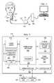
- FIG. 1shows an illustrative stimulation system coupled to a human cranial nerve in accordance with various embodiments
- FIG. 2shows a block diagram of the implantable medical device as shown in FIG. 1 , in accordance with various embodiments;
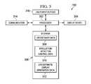
- FIG. 3shows a block diagram of the control unit, as shown in FIG. 1 , in accordance with various embodiments;
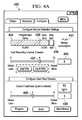
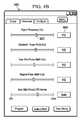
- FIGS. 4A-4Dshows exemplary graphical displays provided by the control unit, as shown in FIG. 1 , in accordance with various embodiments.
- FIG. 5shows a flow diagram of an illustrative method for predicting longevity of the implantable medical device, as shown in FIG. 1 , in accordance with various embodiments.
- softwareincludes any executable code capable of running on a processor, regardless of the media used to store the software.
- code stored in memorye.g., non-volatile memory
- embedded firmwareis included within the definition of software.
- Embodiments of the present disclosureprovide device longevity estimates in a graphical form that highlights the effects of open-loop and closed-loop therapy on IMD operational life.
- Embodimentsare configured to gather closed-loop operational information from an implanted IMD and model the effects of closed-loop therapy on IMD life.
- Embodimentsalso allow investigation of the effects of closed-loop therapy with no corresponding reduction in operable IMD life.
- FIG. 1illustrates an implantable medical device 110 having a main body 112 comprising an enclosure or can 121 with a connector 114 (also referred to as the header) for connecting to leads 122 .
- the IMD 110is implanted in a patient's chest in a pocket or cavity formed by the implanting surgeon just below the skin, similar to the implantation procedure for a pacemaker pulse generator.
- a stimulating nerve electrode assembly 125preferably comprising an electrode pair, conductively couples to the distal end of an insulated and electrically conductive lead assembly 122 , which preferably comprises a pair of lead wires (one wire for each electrode of an electrode pair).
- Lead assembly 122is attached at its proximal end to the connector 114 on can 121 .
- the electrode assembly 125is surgically coupled to a cranial nerve, such as a vagus nerve 127 in the patient's neck.
- the electrode assembly 125preferably comprises a bipolar stimulating electrode pair, such as the electrode pair described in U.S. Pat. No. 4,573,481, which is incorporated herein by reference. Persons of skill in the art will appreciate that many electrode designs could be used in embodiments of the present disclosure.
- the two electrodesare preferably wrapped around the vagus nerve, and the electrode assembly 125 preferably is secured to the nerve 127 by a spiral anchoring tether such as that disclosed in U.S. Pat. No. 4,979,511, which is incorporated herein by reference.
- Lead assembly 122may be secured, while retaining the ability to flex with movement of the chest and neck, by a suture connection to nearby tissue.
- the IMD 110may be controlled or programmed with a control unit 150 (e.g., a computer including any type of stationary, mobile, or handheld computing device) and a programming wand 155 to facilitate wireless communication between the control unit 150 and the IMD 110 .
- the programming wand 155permits noninvasive communication with the IMD 110 after the latter is implanted.
- the control unit 150uses one or more channels in the Medical Implant Communications Service (MICS) bandwidths
- MIMSMedical Implant Communications Service
- the programming wand 155may be omitted to permit more convenient communication directly between the control unit 150 and the IMD 110 .
- MIMSMedical Implant Communications Service
- an estimate of longevity of a power source powering the IMD 110is first made with the IMD 110 programmed to deliver only open-loop therapy, and to record when closed-loop therapy would have been delivered had closed-loop therapy been enabled.
- the recorded datamay be provided to the control unit 150 in real-time or may be stored in IMD 110 for subsequent transfer to the control unit 150 .
- the recorded datacan then be used to estimate power source longevity.
- the estimationmay be used to adjust IMD 110 parameters in consideration of estimated power source longevity and, if desired, closed-loop stimulation may thereafter be enabled. Furthermore, the estimation may be used to adjust IMD 110 parameters in consideration of estimated power source longevity in both the presence and absence of closed-loop therapy.
- an initial longevity estimateis based on both an open-loop therapy program and predicted closed-loop therapy (based on the patient's personal medical condition history, event detector performance capabilities, and/or one or more of a variety of other factors).
- the initial longevity estimatemay occur using the IMD 110 and the control unit 150 , or it may occur in a surrogate environment, such as a computer based simulation.
- the rate of closed-loop therapy that is actually provided by the IMD 110 while the IMD 110 is implanted and operating inside the patient's bodyi.e., the rate of closed-loop therapy “in real life”
- the logmay be provided in real-time to the control unit 150 . In either case, the actual closed-loop therapy data is used to refine the initial estimate regarding longevity of the IMD 110 .
- Initial estimates and refinements theretopreferably are performed by the control unit 150 but also may be performed by the IMD 110 . In some cases, portions of the initial estimates and/or refinements may be performed by the IMD 110 with the remainder of the estimates and/or refinements performed by the control unit 150 . Both the initial estimates and refined predictions are displayed or otherwise provided to an end-user of the control unit 150 (e.g., the patient's physician).
- the end-usersuch as the physician or patient, may adjust IMD 110 closed-loop algorithm parameters (e.g., event detection thresholds, stimulation current, etc.) in light of the estimated longevity and/or efficacy of the current therapy.
- the end-useralso may enable or disable responsive, closed-loop therapy by the IMD 110 . Further, the end-user may adjust the open-loop parameters (e.g., frequency, amplitude, pulse width) or disable open-loop therapy based on the performance and prediction information provided about all modes of therapy.
- the IMD 110 illustrated in FIG. 1provides electrical stimulation to a cranial nerve, such as the vagus nerve.
- a cranial nervesuch as the vagus nerve.
- the embodiments of the present disclosureare not limited to implantable devices that deliver electrical stimulation to a cranial nerve. Therapy may be delivered to any nerve, tissue, structure, or system of the body.
- the embodiments of the present disclosureare not limited to implantable devices that deliver electrical stimulation as a therapy. Any other type of therapy delivered by an implantable device may be used, such as a drug/chemical dosage delivery therapy, mechanical therapy (e.g., vibrations), optical, sound, or any other type of electromagnetic radiation therapy, or combination thereof.
- FIG. 2illustrates a block diagram of IMD 110 for performing neurostimulation in accordance with embodiments of the present disclosure.
- the IMD 110comprises a power source 210 , a power-source controller 220 , a stimulation controller 230 , a power regulation unit 240 , a stimulation unit 250 , a communication unit 260 , and storage 280 .
- the stimulation controller 230 and stimulation unit 250together form stimulation logic 255 .
- Storage 280may be used for storing various program codes, starting data, and the like. More specifically, the storage 280 stores the parameter values that govern the rate and level of stimulation provided by the stimulation logic 255 . The stored parameter values also enable delivery and/or logging of stimulation administered or events detected based on the different categories of stimulation (e.g., open-loop, automatically-initiated, manually-initiated). Information regarding the stimulation administered and/or stimulation trigger events detected is stored as stimulation data and counts 282 in the storage 280 .
- the stimulation data and counts 282may comprise a count of open-loop stimulations administered, a count of automatic stimulation trigger events detected, a count of automatic stimulation events administered, a count of received manually-initiated stimulation requests, and a count of manually-initiated stimulations delivered.
- the stored count valuesmay be provided to the control unit 150 to facilitate prediction of the operational life of the IMD 110 .
- the power source 210may comprise a battery, which may be rechargeable or non-rechargeable. Other power sources, such as capacitors, may also be used.
- the power source 210provides power for the operation of the IMD 110 , including electronic operations and stimulation bursts.
- Power source 210in one embodiment, may be a lithium-thionyl chloride cell or a lithium/carbon monofluoride (LiCFx) cell.
- the terminals of the power source 210preferably electrically couple to an input side of the power-source controller 220 and the power regulation unit 240 .
- the power source 210may be any type of rechargeable/replenishable source, or any type of non-rechargeable/non-replenishable source operative to provide power to the IMD 110 .
- the power-source controller 220preferably comprises circuitry for controlling and monitoring the flow of electrical power to various electronic and stimulation-delivery portions of the IMD 110 (such as the components 230 , 240 , 250 , 260 and 280 illustrated in FIG. 2 ). More particularly, the power-source controller 220 is capable of monitoring the power consumption or charge depletion of the IMD 110 , measuring the voltage across the power source 210 , and generating elective replacement and/or end-of-service signals.
- the communication unit 260facilitates communication between the IMD 110 and the control unit 150 , as shown.
- the control unit 150may be a device that is capable of programming various components and stimulation parameters of the IMD 110 .
- the control unit 150is a computer system capable of electronic communications, programming, and executing a data-acquisition program.
- the control unit 150may be controlled by a healthcare provider such as a physician in, for example, a doctor's office, or may be controlled by the patient.
- the control unit 150may be used to download various parameters and program software into the IMD 110 for programming the operation of the IMD.
- the control unit 150may also receive and upload various status conditions and other data from the IMD 110 .
- the communication unit 260may comprise hardware, software executed by a processor, or any combination thereof. Communications between the control unit 150 and the communication unit 260 may occur via a wireless or other type of communication, illustrated generally by line 275 in FIG. 2 .
- the power regulation unit 240is capable of regulating power delivered by the power source 210 to particular components of the IMD 110 according to their needs and functions.
- the power regulation unit 240may perform a voltage conversion to provide appropriate voltages and/or currents for the operation of the components.
- the power regulation unit 240may comprise hardware, software executed by a processor, or any combination thereof.
- the communication unit 260is capable of providing transmission and reception of electronic signals to and from a control unit 150 .
- Stimulation controller 230defines the electrical stimulation pulses to be delivered as part of a burst to the nerve tissue according to parameters and waveforms that may be programmed into the IMD 110 using the control unit 150 or that may be pre-programmed into the controller 230 prior to or after implantation of the IMD 110 into the patient's body.
- the stimulation controller 230controls the operation of the stimulation unit 250 , which generates the stimulation pulses comprising a burst according to the parameters defined by the controller 230 and, in some embodiments, provides these pulses to the lead assembly 122 and electrode assembly 125 .
- Stimulation pulses provided by the IMD 110may vary widely across a range of parameters.
- the stimulation controller 230may comprise hardware, software executed by a processor, or any combination thereof.
- the detection logic 270detects various events that may trigger delivery of a stimulation burst by the stimulation logic 255 (stimulation controller 230 and stimulation unit 250 ). For example, in some cases, the stimulation controller 230 and the stimulation unit 250 may deliver a stimulation burst in response to detection of an impending or already-occurring seizure based on one or more of the patient's cardiac parameters (e.g., heart rate, rate of change of heart rate, heart rate variability, etc.). However, detection logic 270 may be implemented anywhere on the patient's body to detect any type of event.
- the detection logic 270may be configured to detect events such as patterns of electrical activity in the brain, heart, or muscles, cardiac rhythms, blood pressure, respiratory patterns, etc. indicative of a condition treatable by the IMD.
- the detection logic 270may be disposed in a location other than the patient's body to detect some other type of event independent of the patient's body (e.g., a request for a stimulation burst initiated by the patient).
- Detection logic 270may include a sensor (e.g., a sensor that detects a condition of the patient, or patient input, such as a tap or magnetic input apparatus).
- the detection logic 270may reside inside the IMD 110 and may be comprised of hardware, software executable by a processor, or any combination thereof. Upon detecting an event, the detection logic 270 causes the stimulation controller 230 to activate the stimulation unit 250 in response to the detected event.
- One or more of the blocks 210 - 280may comprise hardware, software executed by a processor, or any combination thereof.
- FIG. 3shows a block diagram of the control unit 150 , as shown in FIG. 1 , in accordance with various embodiments of the invention.
- the control unit 150includes a processor 302 , storage 306 , a display device 304 , a communication unit 314 , and user input devices 316 .
- the control unit 150may be implemented using any of various computing devices, such as desktop computer, a laptop/notebook computer, a tablet computer, a personal digital assistant (PDA), a smartphone, etc.
- PDApersonal digital assistant
- the processor 302may a general purpose microprocessor, a digital signal processor, a microcontroller, or the like configured to execute instructions retrieved from a computer readable medium.
- a processormay include execution units (e.g., fixed point, floating point, integer, etc.), storage (e.g., registers, memory, etc.), instruction decoding, peripherals (e.g., interrupt controllers, timers, direct memory access controllers, etc.), input/output systems (e.g., serial ports, parallel ports, etc.) and various other components and sub-systems.
- execution unitse.g., fixed point, floating point, integer, etc.
- storagee.g., registers, memory, etc.
- instruction decodinge.g., peripherals, e.g., interrupt controllers, timers, direct memory access controllers, etc.
- input/output systemse.g., serial ports, parallel ports, etc.
- the display device 304may be a video display device, such as a liquid crystal display, a cathode ray display, a plasma display, an organic light emitting diode display, a vacuum fluorescent display, an electroluminescent display, an electronic paper display, a projection display, or other type of display or output device suitable for conveying information to a user.
- the display device 304may be coupled to the processor 304 via a graphics adapter (not shown), or by other techniques known in the art.
- the display device 304may be remote from the processor 302 and data to be displayed may be transferred from the processor 302 to the display device 304 via a network.
- the communication unit 314may be configured to provide the control unit 150 with one or modes of communication.
- the communication unit 314may provide wireless communication with the IMD 110 via one or more channels in the MICS.
- Communication with the programming wand 155may be provided using any of a variety of wired signaling protocols (e.g., RS-232, RS-485, universal serial bus, etc) or any other wireless signaling protocols.
- the communication unit 314may also allow the control unit 150 to connect to one or more wired or wireless networks, for example, a network in accordance with IEEE 802.11, IEEE 802.3, Ethernet, a cellular network, etc.
- the user input device 316allows a user (e.g., a physician) to control and/or provide information to the control unit 150 .
- the user input device 316may, for example, be any one or more of a keyboard, a mouse, a trackball, a touchpad, a touch screen, a keypad, buttons, a microphone and voice recognition system, a camera, a motion detection system, etc.
- the processor 302may provide control information to the user input device 316 , and Information input via the user input device 316 is transferred to and manipulated by the processor 302 .
- the storage 306is a computer readable medium that may store instructions for execution by the processor 302 , and other data for use by the processor 302 .
- the storage 302may include one or more types of non-volatile and/or volatile memory including: a hard disk, an optical disk, FLASH memory, read-only memory, random access memory, and/or other types of magnetic, optical, or semiconductor storage.
- the storage 306may be external to the IMD 110 or may be the storage 280 of FIG. 2 . Additionally, the execution of one or more of the instructions may be performed by the processor 225 of FIG. 2 .
- the data stored in the storage 306may be used by the processor 225 of FIG. 2 .
- the storage 306stores life estimate/display generation data 312 , stimulation/detection control data 310 , and IMD life estimates data 308 .
- the life estimate/display generation data 312 and the stimulation/detection control data 310may include instructions that are executable by the processor 302 .
- the life estimate/display generation data 312includes instructions, that when executed by the processor 302 , estimate the operable life of the IMD 110 (i.e., estimates the life of the power source 210 ), and generates displays of the operable life estimates for viewing on the display device 304 .
- the operable life or longevity of the IMD 110is the time period over which the power source 210 provides sufficient energy to guarantee proper operation of the IMD 110 .
- the operable life estimates generated by the processor 302 using the life estimate/display generation data 312are based on the capacity of the power source 210 consumed (e.g., charge consumed) by open-loop stimulation and closed-loop stimulation (automatic and manually-initiated). Because the rate of future closed-loop stimulations to be provided affects power source 210 life, but is difficult to accurately ascertain, some embodiments of the life estimate/display generation data 312 predict power source 210 life based on a measured rate of past closed-loop stimulation or past closed-loop stimulation trigger events recorded by the IMD 110 during an operating session (an interval of, for example, a period of weeks).
- Some embodiments of the life estimate/display generation module 312compute a power source life estimate (i.e., an estimate of the operable life of the IMD 110 ) based on the number of open-loop stimulations, automatic stimulations/stimulation requests, and manually-initiated stimulations/stimulation requests recorded by the IMD 110 in an operating session, in conjunction with the corresponding stimulation parameters (e.g., stimulation pulse width, current, frequency, etc.) applicable to each stimulation category (e.g., open-loop, automatic, manual).
- Operable life estimates provided by such embodimentsmay reflect the predicted life of the power source 210 based on the application of the measured rate of stimulation for each stimulation category using the corresponding stimulation parameters over the entire life of the power source 210 . That is, an operable life estimate predicts what the life of the power source 210 would be if measured stimulation rates and corresponding stimulation parameters were applied over the full (i.e., from beginning to end) life of the IMD 110 .
- a life estimate display generated from the life estimate/display generation data 312identifies what portions of the total estimated operable life of the IMD 110 are consumed by open-loop stimulations, automatic stimulations, and manually-initiated stimulations.
- the control unit 150allows the user to adjust the stimulation/detection parameters to provide more or less detection sensitivity for automatic stimulation events, and more or less energy per stimulation for each stimulation category thereby tuning operation of the IMD 110 to achieve a desired operable IMD life.
- the usermay reduce the sensitivity of event detection that initiates automatic stimulation, thereby reducing the number of events detected, or the user may reduce the stimulation energy applied in response to a detected event.
- the stimulation/detection control module 310when executed by the processor 302 , allows the user to input information for controlling the sensitivity of event detection for automatic stimulation.
- FIG. 4Ashows an exemplary display 480 included in a graphical user interface with control and input features provided by the stimulation/detection control software 310 .
- a level of event detection sensitivitymay entered by a user via a control feature, such as the sliders 482 , 486 , the text boxes 484 , 488 , etc.
- the stimulation/detection control software 310allows the user to control whether the IMD 110 provides stimulation in response to a detected event in addition to logging the detection of the event.
- Buttons 490e.g., radio buttons
- the capability to log detected events without providing automatic stimulationcan be useful for determining the number of events detected at a particular sensitivity level without a corresponding reduction in IMD life.
- the display 480also includes a graphical display 492 of the estimated life of the IMD 110 .
- the estimated life display 492is broken down into segments 494 , 496 , and 498 showing a portion of total IMD life respectively consumed by open-loop, automatic, and manually-initiated stimulations.
- the estimated life display segment 496 corresponding to automatic stimulationis updated in response to changing the event detection sensitivity, thereby providing the user with feedback regarding the effect of a change in sensitivity on IMD life.
- An indicationis made to the user (e.g., via the graphical display 492 ) to delineate actual counts (e.g., from previous recording intervals).
- FIG. 4Bshows an exemplary display 460 , included in a graphical user interface generated by the stimulation/detection control module 310 , for setting parameters (e.g., frequency, pulse width, etc.) related to open-loop, automatic, and manually-initiated stimulations.
- Each parameteris user adjustable using a control feature, such as the slider 462 , the text box 464 , etc. Changes to these parameters may affect the operable life of the IMD 110 , and therefore may be reflected in an update of the graphical display of operable life provided to the user (e.g., display 492 ).
- FIG. 4Cshows an exemplary display 440 , included in a graphical user interface generated by the stimulation/detection control module 310 , for setting dose schedule and setting output current for open-loop, automatic, and manually-initiated stimulations.
- Each parameteris user adjustable using a control feature, such as the slider 442 , the text box 444 , etc.
- the display 440also includes a graphical display 446 of the estimated life of the IMD 110 based on stimulation and detection parameters used by the IMD 110 during a previous use interval (e.g., the last use session).
- An additional graphical display 448 of estimated IMD lifeshows predicted IMD life based on the current setting applied to the stimulation and detection parameters.
- the estimated life displays 446 , 448are broken into segments showing a portion of total IMD life respectively consumed by open-loop, automatic, and manually-initiated stimulations.
- a plurality of life estimates 308may be recorded in the storage 282 and 306 .
- Each stored life estimatecorresponds to a log of stimulations and detected events recorded by the IMD 110 during an operating session, and the stimulation parameters applied during the operating session.
- One or more of the recorded life estimatesmay be displayed to provide a history of life estimates for the IMD 110 .
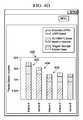
- FIG. 4Dshows a graphical display 400 of a plurality of life estimates 308 .
- Each life estimatecorresponds to a stored life estimate as described above, and shows a portion of IMD 110 operable life consumed by open-loop, automatic, and manually-initiated stimulations.
- the operable life of the IMD 110is estimated to be less than 5 years.
- Any number of parameters, in addition to those provided in FIGS. 4A-Dmay be provided to modify the different types of stimulation. For example, a physician may set a threshold that limits the number of manually-initiated stimulations within a period of time to limit battery consumption and health risks (e.g., side effects) from unnecessary stimulation.
- FIG. 5shows a flow diagram of an illustrative method for predicting longevity of the IMD 110 in accordance with various embodiments of the invention. Though depicted sequentially as a matter of convenience, at least some of the actions shown can be performed in a different order and/or performed in parallel. Additionally, some embodiments may perform only some of the actions shown. Embodiments of the method may be implemented by the IMD 110 and/or the control unit 150 as disclosed herein. In some embodiments, at least some of the operations of FIG. 5 , as well as other operations described herein, can be implemented as instructions stored in a computer readable medium and executed by a processor.
- a user of the control unit 150assigns a first set of values to IMD control parameters.
- the control parametersmay include open-loop stimulation rate and level, automatic stimulation level, manually-initiated stimulation level, event detection level for automatic stimulation, and automatic and manually-initiated stimulation/logging enablement controls.
- the first set of valuesconfigures the IMD 110 to provide open-loop stimulation.
- the rate and level of open-loop stimulationmay be selected to provide the IMD 110 with a desired longevity (e.g., 5-6 years).
- the first set of valuesmay further configure the IMD 110 to disable automatic stimulation and manually-initiated stimulation, while enabling logging of detection of events that trigger automatic stimulation and logging of requests for manually-initiated stimulation. If disabled, automatic and manually-initiated stimulation do not contribute to depletion of the power source 210 , but detected event logging allows for acquisition of potential stimulation information that can be used to estimate energy consumption had closed-loop stimulation been enabled.
- archived longevity data(e.g., generalized longevity information based on measured longevity of previously implanted IMDs using known open-loop and/or closed-loop stimulation parameters) may be applied to select the open-loop and closed-loop stimulation parameters and to estimate longevity of the IMD 110 .
- the archived longevity datamay be non-patient specific, and may be particularly useful in estimating IMD longevity before patient specific longevity information is acquired.
- embodimentsmay apply archived longevity data to estimating the longevity of the IMD 110 , alone or in combination with patient specific longevity information, at any point in the life of the IMD 110 .
- the IMD 110is operated for a first interval (e.g., a session covering a period of weeks) as configured by the first set of values.
- the IMD 110provides open-loop stimulation, and records the number of open-loop stimulations, the number of detected automatic stimulation events, and the number of requests for manually-initiated stimulation in a log 282 in the storage 280 .
- the control unit 150retrieves the stimulation and detected event information logged by the IMD 110 during the operating session.
- the control unit 150may retrieve the logged information via the communication units 260 , 314 .
- the IMD 110provides the information to the control unit 150 during the operating session.
- the control unit 150estimates the operable life of the IMD 110 based on the retrieved stimulation and detected event information.
- the IMD life estimateis further based on the stimulation level parameters (e.g., stimulation current, pulse width, etc.) used by the IMD 110 during the operating session.
- the stimulation level parametersmay be transferred from the IMD 110 to the control unit 150 , or retrieved from control unit storage 306 .
- IMD life estimationincludes determining the energy consumed by the stimulations administered, and stimulations that would have been administered had automatic or manually-initiated stimulation been enabled, and determining the life of power source 210 if the determined session energy consumption were applied over the entire life of the power source 210 .
- the portion of total power source energy consumed by each category of stimulationmay be determined based on the number of stimulations and the charge consumption or potential charge consumption per stimulation for the category during the operating session.
- the control unit 150presents a display (e.g., display 400 ) of the estimated longevity of the IMD 110 .
- the displayshows the total estimated life of the IMD 110 , and shows what portion of the total estimated life is consumed by each of open-loop stimulation, automatic stimulation, and manually-initiated stimulation based on the stimulation rate, stimulation level, and other stimulation parameters applied during the operating session.
- IMD life display 402 of FIG. 4Dis an example of a display of an IMD life estimate wherein the IMD 110 is operated using open-loop stimulation configured to provide an estimated six year power source life, automatic and manually-initiated stimulation are disabled, and detected automatic stimulation events and requests for manually-initiated stimulation are logged.
- the IMD control valuesare adjusted based on the estimated IMD life.
- Open-loop stimulation rate and/or levelmay be adjusted to allow for the anticipated energy consumption of automatic and manually-initiated stimulation.
- Automatic stimulation event detection sensitivitymay be adjusted based on the number and/or level of events detected in the previous operating session.
- Stimulation levels for automatic and/or manually-initiated stimulationmay be adjusted to provide a desired longevity for the power source 210 .
- Automatic and/or manually-initiated stimulationmay be disabled to allow for further acquisition of detected event information without affecting the life of the power source 210 , or automatic and/or manually-initiated stimulation may be enabled.
- the control unit 150generates a new operable life estimate for the IMD 110 based on the adjusted IMD control values.
- a display representing the new estimate of IMD lifeis presented, by the control unit 150 , in block 516 .
- the displayshows total estimated IMD life and portions of IMD life allocated to open-loop, automatic, and manually-initiated stimulation allowing the user to further adjust the stimulation parameters and receive immediate feedback as to the effects of the adjustments on IMD life.
- IMD life display 404 of FIG. 4Dis an example of a display of an IMD life estimate wherein the automatic stimulation level and/or detection sensitivity has been adjusted based on the detected number of automatic stimulation events (or IMD life potentially consumed by automatic stimulation events) of the prior operating session (as shown in display 402 ).
- the IMD 110is operated for a second session ( FIG. 4D , Interval B) using open-loop stimulation configured to provide an estimated six year power source life, automatic stimulation and manually-initiated stimulation are disabled, and detected closed-loop stimulation events are logged.
- IMD life display 406 of FIG. 4Dis an example of a display of an IMD life estimate wherein the open-loop stimulation rate and level has been adjusted to reduce the scheduled open-loop stimulation, but the automatic stimulation and manually-initiated stimulation remain unchanged.
- the IMD 110is operated for a third session (Interval C) with open-loop stimulation, automatic stimulation, and manually-initiated stimulation enabled and configured to provide an estimated 6 year operational life for the IMD 110 .
- Interval Cthird session
- the efficacy of the therapymay be considered when adjusting the therapy parameters to provide the most efficacious therapy using the least amount of power.
- the adjustments to the parameters and considerations of efficacy and battery lifemay be applied in an iterative fashion. In this manner, the needed level of therapy may be provided to the patient while maximizing the life of the IMD power source.
Landscapes
- Health & Medical Sciences (AREA)
- Life Sciences & Earth Sciences (AREA)
- Engineering & Computer Science (AREA)
- Animal Behavior & Ethology (AREA)
- Public Health (AREA)
- Nuclear Medicine, Radiotherapy & Molecular Imaging (AREA)
- Radiology & Medical Imaging (AREA)
- Biomedical Technology (AREA)
- Veterinary Medicine (AREA)
- General Health & Medical Sciences (AREA)
- Neurosurgery (AREA)
- Neurology (AREA)
- Biophysics (AREA)
- Physiology (AREA)
- Human Computer Interaction (AREA)
- Cardiology (AREA)
- Heart & Thoracic Surgery (AREA)
- Electrotherapy Devices (AREA)
Abstract
Description
Claims (21)
Priority Applications (3)
| Application Number | Priority Date | Filing Date | Title |
|---|---|---|---|
| US13/086,667US8761884B2 (en) | 2011-04-14 | 2011-04-14 | Device longevity prediction for a device having variable energy consumption |
| US14/276,652US9126054B2 (en) | 2011-04-14 | 2014-05-13 | Device longevity prediction for a device having variable energy consumption |
| US14/817,073US9242110B2 (en) | 2011-04-14 | 2015-08-03 | Device longevity prediction for a device having variable energy consumption |
Applications Claiming Priority (1)
| Application Number | Priority Date | Filing Date | Title |
|---|---|---|---|
| US13/086,667US8761884B2 (en) | 2011-04-14 | 2011-04-14 | Device longevity prediction for a device having variable energy consumption |
Related Child Applications (1)
| Application Number | Title | Priority Date | Filing Date |
|---|---|---|---|
| US14/276,652DivisionUS9126054B2 (en) | 2011-04-14 | 2014-05-13 | Device longevity prediction for a device having variable energy consumption |
Publications (2)
| Publication Number | Publication Date |
|---|---|
| US20120265266A1 US20120265266A1 (en) | 2012-10-18 |
| US8761884B2true US8761884B2 (en) | 2014-06-24 |
Family
ID=47006991
Family Applications (3)
| Application Number | Title | Priority Date | Filing Date |
|---|---|---|---|
| US13/086,667Active2032-01-16US8761884B2 (en) | 2011-04-14 | 2011-04-14 | Device longevity prediction for a device having variable energy consumption |
| US14/276,652ActiveUS9126054B2 (en) | 2011-04-14 | 2014-05-13 | Device longevity prediction for a device having variable energy consumption |
| US14/817,073ActiveUS9242110B2 (en) | 2011-04-14 | 2015-08-03 | Device longevity prediction for a device having variable energy consumption |
Family Applications After (2)
| Application Number | Title | Priority Date | Filing Date |
|---|---|---|---|
| US14/276,652ActiveUS9126054B2 (en) | 2011-04-14 | 2014-05-13 | Device longevity prediction for a device having variable energy consumption |
| US14/817,073ActiveUS9242110B2 (en) | 2011-04-14 | 2015-08-03 | Device longevity prediction for a device having variable energy consumption |
Country Status (1)
| Country | Link |
|---|---|
| US (3) | US8761884B2 (en) |
Families Citing this family (19)
| Publication number | Priority date | Publication date | Assignee | Title |
|---|---|---|---|---|
| US20140277248A1 (en)* | 2013-03-15 | 2014-09-18 | Medtronic, Inc. | Graphical display of remaining longevity of energy source of implantable medical device and method |
| US9433796B2 (en) | 2013-09-03 | 2016-09-06 | Boston Scientific Neuromodulation Corporation | Medical device application for an external device using data logged at an implantable medical device |
| US9186518B2 (en) | 2013-09-06 | 2015-11-17 | Boston Scientific Neuromodulation Corporation | Medical device application for configuring a mobile device into an external controller for an implantable medical device |
| US9782594B2 (en)* | 2013-12-20 | 2017-10-10 | Cardiac Pacemakers, Inc. | Leadless pacemaker with end-of-life protection |
| US9643025B2 (en) | 2014-09-08 | 2017-05-09 | Medtronic, Inc. | Multi-primary transformer charging circuits for implantable medical devices |
| US9579517B2 (en) | 2014-09-08 | 2017-02-28 | Medtronic, Inc. | Transformer-based charging circuits for implantable medical devices |
| US9861828B2 (en) | 2014-09-08 | 2018-01-09 | Medtronic, Inc. | Monitoring multi-cell power source of an implantable medical device |
| US9604071B2 (en) | 2014-09-08 | 2017-03-28 | Medtronic, Inc. | Implantable medical devices having multi-cell power sources |
| US9539435B2 (en) | 2014-09-08 | 2017-01-10 | Medtronic, Inc. | Transthoracic protection circuit for implantable medical devices |
| US9724528B2 (en) | 2014-09-08 | 2017-08-08 | Medtronic, Inc. | Multiple transformer charging circuits for implantable medical devices |
| US9861827B2 (en) | 2014-09-08 | 2018-01-09 | Medtronic, Inc. | Implantable medical devices having multi-cell power sources |
| US9700669B2 (en)* | 2015-04-16 | 2017-07-11 | Flowonix Medical Incorporated | Patient programmer for implantable drug delivery device |
| US11865337B2 (en) | 2016-01-29 | 2024-01-09 | Brent C. Reider | Regulated and interactive muscle stimulation |
| US10646711B2 (en) | 2016-01-29 | 2020-05-12 | Brent C. Reider | Interactive muscle training system and method |
| US11724100B2 (en) | 2016-01-29 | 2023-08-15 | Brent C. Reider | Regulated and interactive muscle stimulation using sensory regulated EMG triggered stimulation for forging neural pathways |
| US10307589B2 (en)* | 2016-01-29 | 2019-06-04 | Brent C. Reider | Interactive muscle training device and method |
| US10639481B2 (en) | 2018-01-08 | 2020-05-05 | Medtronic, Inc. | Power source longevity |
| CN114582479A (en)* | 2022-03-02 | 2022-06-03 | 苏州景昱医疗器械有限公司 | Control equipment and service life assessment systems |
| CN114764600B (en)* | 2022-04-24 | 2025-05-23 | 东软睿驰汽车技术(沈阳)有限公司 | Life prediction method, device and electronic equipment for new energy vehicle battery pack |
Citations (106)
| Publication number | Priority date | Publication date | Assignee | Title |
|---|---|---|---|---|
| US3796221A (en) | 1971-07-07 | 1974-03-12 | N Hagfors | Apparatus for delivering electrical stimulation energy to body-implanted apparatus with signal-receiving means |
| US4324251A (en) | 1980-06-10 | 1982-04-13 | Pacesetter Systems, Inc. | Battery monitoring means and method for an implantable tissue stimulator |
| US4488555A (en) | 1982-12-13 | 1984-12-18 | Mieczyslaw Mirowski | Battery condition warning system for medical implant |
| US4556061A (en) | 1982-08-18 | 1985-12-03 | Cordis Corporation | Cardiac pacer with battery consumption monitor circuit |
| US4686990A (en) | 1985-10-02 | 1987-08-18 | Siemens Aktiengesellschaft | Battery test circuit for a heart pacemaker |
| US4702254A (en) | 1983-09-14 | 1987-10-27 | Jacob Zabara | Neurocybernetic prosthesis |
| US4715381A (en) | 1985-10-02 | 1987-12-29 | Siemens Aktiengesellschaft | Battery test circuit for a heart pacemaker |
| US4850356A (en) | 1980-08-08 | 1989-07-25 | Darox Corporation | Defibrillator electrode system |
| US4867164A (en) | 1983-09-14 | 1989-09-19 | Jacob Zabara | Neurocybernetic prosthesis |
| US4899750A (en) | 1988-04-19 | 1990-02-13 | Siemens-Pacesetter, Inc. | Lead impedance scanning system for pacemakers |
| US4964407A (en) | 1988-08-29 | 1990-10-23 | Intermedics, Inc. | Method and apparatus for assuring pacer programming is compatible with the lead |
| US5025807A (en) | 1983-09-14 | 1991-06-25 | Jacob Zabara | Neurocybernetic prosthesis |
| US5127404A (en) | 1990-01-22 | 1992-07-07 | Medtronic, Inc. | Telemetry format for implanted medical device |
| US5137021A (en) | 1990-11-29 | 1992-08-11 | Medtronic, Inc. | Lead current measurement circuit |
| US5137020A (en) | 1990-11-29 | 1992-08-11 | Medtronic, Inc. | Battery impedance measurement apparatus |
| US5146920A (en) | 1989-11-20 | 1992-09-15 | Sanyo Electric Co., Ltd. | Wireless low-frequency medical treatment device with pulse interruption based upon electrode contact with the body |
| US5154172A (en) | 1989-11-13 | 1992-10-13 | Cyberonics, Inc. | Constant current sources with programmable voltage source |
| US5179950A (en) | 1989-11-13 | 1993-01-19 | Cyberonics, Inc. | Implanted apparatus having micro processor controlled current and voltage sources with reduced voltage levels when not providing stimulation |
| US5188104A (en) | 1991-02-01 | 1993-02-23 | Cyberonics, Inc. | Treatment of eating disorders by nerve stimulation |
| US5193538A (en) | 1989-02-14 | 1993-03-16 | Siemens Aktiengesellschaft | In vivo implantable medical device with battery monitoring circuitry |
| US5201865A (en) | 1991-10-28 | 1993-04-13 | Medtronic, Inc. | Medical lead impedance measurement system |
| US5201808A (en) | 1992-02-10 | 1993-04-13 | Telectronics Pacing Systems, Inc. | Minute volume rate-responsive pacemaker employing impedance sensing on a unipolar lead |
| US5215086A (en) | 1991-05-03 | 1993-06-01 | Cyberonics, Inc. | Therapeutic treatment of migraine symptoms by stimulation |
| US5222494A (en) | 1991-07-31 | 1993-06-29 | Cyberonics, Inc. | Implantable tissue stimulator output stabilization system |
| US5231988A (en) | 1991-08-09 | 1993-08-03 | Cyberonics, Inc. | Treatment of endocrine disorders by nerve stimulation |
| US5263480A (en) | 1991-02-01 | 1993-11-23 | Cyberonics, Inc. | Treatment of eating disorders by nerve stimulation |
| US5269303A (en) | 1991-02-22 | 1993-12-14 | Cyberonics, Inc. | Treatment of dementia by nerve stimulation |
| US5299569A (en) | 1991-05-03 | 1994-04-05 | Cyberonics, Inc. | Treatment of neuropsychiatric disorders by nerve stimulation |
| US5330515A (en) | 1992-06-17 | 1994-07-19 | Cyberonics, Inc. | Treatment of pain by vagal afferent stimulation |
| US5335657A (en) | 1991-05-03 | 1994-08-09 | Cyberonics, Inc. | Therapeutic treatment of sleep disorder by nerve stimulation |
| US5352962A (en) | 1993-04-19 | 1994-10-04 | Sug Lithography Systems, Inc. | Brushless polyphase reduced force variation motor |
| US5352968A (en) | 1992-05-28 | 1994-10-04 | Apple Computer, Inc. | Battery charge state determination |
| US5372607A (en) | 1993-06-23 | 1994-12-13 | Medtronic, Inc. | Method and apparatus for monitoring pacemaker intervals |
| US5391193A (en) | 1993-02-05 | 1995-02-21 | Medtronic, Inc. | Method and apparatus for battery depletion monitoring |
| US5431692A (en) | 1993-08-02 | 1995-07-11 | Telectronics Pacing Systems, Inc. | Method and apparatus for testing compatibility of lead polarity and polarity programming of a cardiac stimulator |
| US5458624A (en) | 1993-10-06 | 1995-10-17 | Vitatron Medical, B.V. | Cardiac pacing system with improved end-of-life detector |
| US5496353A (en) | 1993-09-23 | 1996-03-05 | Grandjean; Pierre A. | End-of-life indication system for implantable pulse generator |
| US5507786A (en) | 1994-04-14 | 1996-04-16 | Pacesetter, Inc. | System and method for measuring and storing parametric data pertaining to operating characteristics of an implantable medical device |
| US5522865A (en) | 1989-09-22 | 1996-06-04 | Alfred E. Mann Foundation For Scientific Research | Voltage/current control system for a human tissue stimulator |
| US5534018A (en) | 1994-11-30 | 1996-07-09 | Medtronic, Inc. | Automatic lead recognition for implantable medical device |
| US5540734A (en) | 1994-09-28 | 1996-07-30 | Zabara; Jacob | Cranial nerve stimulation treatments using neurocybernetic prosthesis |
| US5540730A (en) | 1995-06-06 | 1996-07-30 | Cyberonics, Inc. | Treatment of motility disorders by nerve stimulation |
| US5549646A (en) | 1994-12-06 | 1996-08-27 | Pacesetter, Inc. | Periodic electrical lead intergrity testing system and method for implantable cardiac stimulating devices |
| US5571150A (en) | 1994-12-19 | 1996-11-05 | Cyberonics, Inc. | Treatment of patients in coma by nerve stimulation |
| US5620474A (en) | 1995-04-24 | 1997-04-15 | Vitatron Medical, B.V. | System and method for determining indicated pacemaker replacement time based upon battery impedance measurement |
| US5703469A (en) | 1995-06-05 | 1997-12-30 | Honda Giken Kogyo Kabushiki Kaisha | System for determining battery conditions |
| US5707400A (en) | 1995-09-19 | 1998-01-13 | Cyberonics, Inc. | Treating refractory hypertension by nerve stimulation |
| US5713936A (en) | 1995-11-08 | 1998-02-03 | Litronik Batterietechnologie Gmbh & Co. | Implantable medical device with end-of-life battery detection circuit |
| US5741311A (en) | 1996-06-27 | 1998-04-21 | Medtronic, Inc. | Implantable medical device system with method for determining lead condition |
| US5741307A (en) | 1997-01-21 | 1998-04-21 | Pacesetter, Inc. | Method for determining an ICD replacement time |
| US5755742A (en) | 1996-11-05 | 1998-05-26 | Medtronic, Inc. | Cardioversion/defibrillation lead impedance measurement system |
| US5769873A (en) | 1996-10-15 | 1998-06-23 | Pacesetter, Inc. | Meter for measuring battery charge delivered in an implantable device |
| US5814088A (en) | 1997-03-26 | 1998-09-29 | Sulzer Intermedics Inc. | Cardiac stimulator with lead failure detector and warning system |
| US5876425A (en) | 1989-09-22 | 1999-03-02 | Advanced Bionics Corporation | Power control loop for implantable tissue stimulator |
| US5891179A (en) | 1997-11-20 | 1999-04-06 | Paceseter, Inc. | Method and apparatus for monitoring and displaying lead impedance in real-time for an implantable medical device |
| US5897577A (en) | 1997-11-07 | 1999-04-27 | Medtronic, Inc. | Pacing lead impedance monitoring circuit and method |
| US5928272A (en) | 1998-05-02 | 1999-07-27 | Cyberonics, Inc. | Automatic activation of a neurostimulator device using a detection algorithm based on cardiac activity |
| US6016448A (en) | 1998-10-27 | 2000-01-18 | Medtronic, Inc. | Multilevel ERI for implantable medical devices |
| US6073050A (en) | 1998-11-10 | 2000-06-06 | Advanced Bionics Corporation | Efficient integrated RF telemetry transmitter for use with implantable device |
| US6108579A (en) | 1996-04-15 | 2000-08-22 | Pacesetter, Inc. | Battery monitoring apparatus and method for programmers of cardiac stimulating devices |
| US6148235A (en) | 1998-07-17 | 2000-11-14 | Vitatron Medical, B.V. | Implantable stimulator with battery status measurement |
| US6167309A (en) | 1997-09-15 | 2000-12-26 | Cardiac Pacemakers, Inc. | Method for monitoring end of life for battery |
| US6181969B1 (en) | 1998-06-26 | 2001-01-30 | Advanced Bionics Corporation | Programmable current output stimulus stage for implantable device |
| US6185461B1 (en) | 1998-07-01 | 2001-02-06 | Pacesetter, Inc. | System and method for verification of recommended replacement time indication in an implantable cardiac stimulation device |
| US6212431B1 (en) | 1998-09-08 | 2001-04-03 | Advanced Bionics Corporation | Power transfer circuit for implanted devices |
| US20010034541A1 (en) | 1997-09-15 | 2001-10-25 | Cardiac Pacemakers, Inc. | Method for monitoring end of life for battery |
| US6317633B1 (en) | 1999-01-19 | 2001-11-13 | Medtronic, Inc. | Implantable lead functional status monitor and method |
| US6341236B1 (en) | 1999-04-30 | 2002-01-22 | Ivan Osorio | Vagal nerve stimulation techniques for treatment of epileptic seizures |
| US20020022866A1 (en) | 2000-08-17 | 2002-02-21 | Borkan William N. | Multichannel stimulator electronics and methods |
| US6400988B1 (en) | 2000-02-18 | 2002-06-04 | Pacesetter, Inc. | Implantable cardiac device having precision RRT indication |
| US6445951B1 (en) | 1999-10-12 | 2002-09-03 | Pacesetter, Inc. | Implantable cardiac stimulating device incorporating high frequency low amplitude lead impedance measurement |
| US6453198B1 (en) | 2000-04-28 | 2002-09-17 | Medtronic, Inc. | Power management for an implantable medical device |
| US6473644B1 (en) | 1999-10-13 | 2002-10-29 | Cyberonics, Inc. | Method to enhance cardiac capillary growth in heart failure patients |
| US6490486B1 (en) | 2000-04-27 | 2002-12-03 | Pacesetter, Inc. | Implantable cardiac stimulation device and method that monitors displacement of an implanted lead |
| US6490484B2 (en) | 2001-01-24 | 2002-12-03 | Cardiac Pacemakers, Inc. | Apparatus and method for estimating battery condition in implantable cardioverter/defibrillators |
| US20030074037A1 (en) | 2001-10-17 | 2003-04-17 | Rehabilicare, Inc. | Electrical nerve stimulation device |
| US6553263B1 (en) | 1999-07-30 | 2003-04-22 | Advanced Bionics Corporation | Implantable pulse generators using rechargeable zero-volt technology lithium-ion batteries |
| US6587719B1 (en) | 1999-07-01 | 2003-07-01 | Cyberonics, Inc. | Treatment of obesity by bilateral vagus nerve stimulation |
| US6609025B2 (en) | 2001-01-02 | 2003-08-19 | Cyberonics, Inc. | Treatment of obesity by bilateral sub-diaphragmatic nerve stimulation |
| US6622038B2 (en) | 2001-07-28 | 2003-09-16 | Cyberonics, Inc. | Treatment of movement disorders by near-diaphragmatic nerve stimulation |
| US6620186B2 (en) | 2000-05-25 | 2003-09-16 | International Business Machines Corporation | Method and system for medical lead impedance test |
| US6622041B2 (en) | 2001-08-21 | 2003-09-16 | Cyberonics, Inc. | Treatment of congestive heart failure and autonomic cardiovascular drive disorders |
| US6622047B2 (en) | 2001-07-28 | 2003-09-16 | Cyberonics, Inc. | Treatment of neuropsychiatric disorders by near-diaphragmatic nerve stimulation |
| US6648823B2 (en) | 2001-07-31 | 2003-11-18 | Medtronic, Inc. | Method and system of follow-up support for a medical device |
| US6658294B1 (en) | 2001-08-29 | 2003-12-02 | Pacesetter, Inc. | Implantable cardiac device having an impedance monitoring circuit and method |
| US6671552B2 (en) | 2001-10-02 | 2003-12-30 | Medtronic, Inc. | System and method for determining remaining battery life for an implantable medical device |
| US6687538B1 (en) | 2000-06-19 | 2004-02-03 | Medtronic, Inc. | Trial neuro stimulator with lead diagnostics |
| US6721600B2 (en) | 2000-01-19 | 2004-04-13 | Medtronic, Inc. | Implantable lead functional status monitor and method |
| US6745077B1 (en) | 2000-10-11 | 2004-06-01 | Advanced Bionics Corporation | Electronic impedance transformer for inductively-coupled load stabilization |
| US6748273B1 (en) | 1999-07-19 | 2004-06-08 | St. Jude Medical Ab | Method and circuit for determining the battery status in a medical implant |
| US6760624B2 (en) | 2001-12-03 | 2004-07-06 | Cardiac Pacemakers, Inc. | Method and apparatus for measuring lead impedance in an implantable cardiac rhythm management device |
| US6760625B1 (en) | 2001-10-11 | 2004-07-06 | Pacesetter, Inc. | Battery monitoring system for an implantable medical device |
| WO2004075982A1 (en) | 2003-02-21 | 2004-09-10 | Medtronic, Inc. | Implantable neurostimulator programming with battery longevity indication |
| US20040199146A1 (en) | 2003-04-07 | 2004-10-07 | Rogers Charles R. | System and method for monitoring power source longevity of an implantable medical device |
| US6820019B1 (en) | 1999-07-31 | 2004-11-16 | Medtronic, Inc. | Device and method for determining and communicating the remaining life of a battery in an implantable neurological tissue stimulating device |
| US20050088145A1 (en) | 2003-10-23 | 2005-04-28 | Robert Loch | Battery charge indicator such as for an implantable medical device |
| US20050272280A1 (en) | 2001-10-22 | 2005-12-08 | Osypka Thomas P | Lead adaptor having low resistance conductors and/or encapsulated housing |
| US20070150019A1 (en) | 2005-12-15 | 2007-06-28 | Cardiac Pacemakers, Inc | Implantable medical device powered by rechargeable battery |
| US20070213773A1 (en)* | 2001-10-26 | 2007-09-13 | Hill Michael R | Closed-Loop Neuromodulation for Prevention and Treatment of Cardiac Conditions |
| US20070216366A1 (en) | 2006-03-15 | 2007-09-20 | Shoichi Inamine | Method for judging service life of primary battery |
| US20080097544A1 (en)* | 2006-10-20 | 2008-04-24 | Rajesh Krishan Gandhi | Dynamic battery management in an implantable device |
| US20090099625A1 (en)* | 2007-07-20 | 2009-04-16 | Tom Crowley | Elective service indicator based on pulse count for implantable device |
| US20100121591A1 (en) | 2008-11-13 | 2010-05-13 | Lockheed Martin Corporation | Method and apparatus that detects state of charge (soc) of a battery |
| US20100145405A1 (en)* | 2008-12-04 | 2010-06-10 | Pacesetter, Inc. | Systems and Methods for Controlling Ventricular Pacing in Patients with Long Inter-Atrial Conduction Delays |
| US7751891B2 (en) | 2004-07-28 | 2010-07-06 | Cyberonics, Inc. | Power supply monitoring for an implantable device |
| US20100229187A1 (en)* | 2009-03-06 | 2010-09-09 | Manish Marwah | Event detection from attributes read by entities |
Family Cites Families (1)
| Publication number | Priority date | Publication date | Assignee | Title |
|---|---|---|---|---|
| US20080177345A1 (en)* | 2007-01-18 | 2008-07-24 | Schmidt Craig L | Methods for estimating remaining battery service life in an implantable medical device |
- 2011
- 2011-04-14USUS13/086,667patent/US8761884B2/enactiveActive
- 2014
- 2014-05-13USUS14/276,652patent/US9126054B2/enactiveActive
- 2015
- 2015-08-03USUS14/817,073patent/US9242110B2/enactiveActive
Patent Citations (122)
| Publication number | Priority date | Publication date | Assignee | Title |
|---|---|---|---|---|
| US3796221A (en) | 1971-07-07 | 1974-03-12 | N Hagfors | Apparatus for delivering electrical stimulation energy to body-implanted apparatus with signal-receiving means |
| US4324251A (en) | 1980-06-10 | 1982-04-13 | Pacesetter Systems, Inc. | Battery monitoring means and method for an implantable tissue stimulator |
| US4850356A (en) | 1980-08-08 | 1989-07-25 | Darox Corporation | Defibrillator electrode system |
| US4556061A (en) | 1982-08-18 | 1985-12-03 | Cordis Corporation | Cardiac pacer with battery consumption monitor circuit |
| US4488555A (en) | 1982-12-13 | 1984-12-18 | Mieczyslaw Mirowski | Battery condition warning system for medical implant |
| US5025807A (en) | 1983-09-14 | 1991-06-25 | Jacob Zabara | Neurocybernetic prosthesis |
| US4702254A (en) | 1983-09-14 | 1987-10-27 | Jacob Zabara | Neurocybernetic prosthesis |
| US4867164A (en) | 1983-09-14 | 1989-09-19 | Jacob Zabara | Neurocybernetic prosthesis |
| US4686990A (en) | 1985-10-02 | 1987-08-18 | Siemens Aktiengesellschaft | Battery test circuit for a heart pacemaker |
| US4715381A (en) | 1985-10-02 | 1987-12-29 | Siemens Aktiengesellschaft | Battery test circuit for a heart pacemaker |
| US4899750A (en) | 1988-04-19 | 1990-02-13 | Siemens-Pacesetter, Inc. | Lead impedance scanning system for pacemakers |
| US4964407A (en) | 1988-08-29 | 1990-10-23 | Intermedics, Inc. | Method and apparatus for assuring pacer programming is compatible with the lead |
| US5193538A (en) | 1989-02-14 | 1993-03-16 | Siemens Aktiengesellschaft | In vivo implantable medical device with battery monitoring circuitry |
| US5522865A (en) | 1989-09-22 | 1996-06-04 | Alfred E. Mann Foundation For Scientific Research | Voltage/current control system for a human tissue stimulator |
| US5876425A (en) | 1989-09-22 | 1999-03-02 | Advanced Bionics Corporation | Power control loop for implantable tissue stimulator |
| US5154172A (en) | 1989-11-13 | 1992-10-13 | Cyberonics, Inc. | Constant current sources with programmable voltage source |
| US5179950A (en) | 1989-11-13 | 1993-01-19 | Cyberonics, Inc. | Implanted apparatus having micro processor controlled current and voltage sources with reduced voltage levels when not providing stimulation |
| US5146920A (en) | 1989-11-20 | 1992-09-15 | Sanyo Electric Co., Ltd. | Wireless low-frequency medical treatment device with pulse interruption based upon electrode contact with the body |
| US5127404A (en) | 1990-01-22 | 1992-07-07 | Medtronic, Inc. | Telemetry format for implanted medical device |
| US5344431A (en) | 1990-01-22 | 1994-09-06 | Medtronic, Inc. | Method and apparatus for determination of end-of-service for implantable devices |
| US5137021A (en) | 1990-11-29 | 1992-08-11 | Medtronic, Inc. | Lead current measurement circuit |
| US5137020A (en) | 1990-11-29 | 1992-08-11 | Medtronic, Inc. | Battery impedance measurement apparatus |
| US5188104A (en) | 1991-02-01 | 1993-02-23 | Cyberonics, Inc. | Treatment of eating disorders by nerve stimulation |
| US5263480A (en) | 1991-02-01 | 1993-11-23 | Cyberonics, Inc. | Treatment of eating disorders by nerve stimulation |
| US5269303A (en) | 1991-02-22 | 1993-12-14 | Cyberonics, Inc. | Treatment of dementia by nerve stimulation |
| US5335657A (en) | 1991-05-03 | 1994-08-09 | Cyberonics, Inc. | Therapeutic treatment of sleep disorder by nerve stimulation |
| US5299569A (en) | 1991-05-03 | 1994-04-05 | Cyberonics, Inc. | Treatment of neuropsychiatric disorders by nerve stimulation |
| US5215086A (en) | 1991-05-03 | 1993-06-01 | Cyberonics, Inc. | Therapeutic treatment of migraine symptoms by stimulation |
| US5222494A (en) | 1991-07-31 | 1993-06-29 | Cyberonics, Inc. | Implantable tissue stimulator output stabilization system |
| US5231988A (en) | 1991-08-09 | 1993-08-03 | Cyberonics, Inc. | Treatment of endocrine disorders by nerve stimulation |
| US5201865A (en) | 1991-10-28 | 1993-04-13 | Medtronic, Inc. | Medical lead impedance measurement system |
| US5201808A (en) | 1992-02-10 | 1993-04-13 | Telectronics Pacing Systems, Inc. | Minute volume rate-responsive pacemaker employing impedance sensing on a unipolar lead |
| US5352968A (en) | 1992-05-28 | 1994-10-04 | Apple Computer, Inc. | Battery charge state determination |
| US5330515A (en) | 1992-06-17 | 1994-07-19 | Cyberonics, Inc. | Treatment of pain by vagal afferent stimulation |
| US5391193A (en) | 1993-02-05 | 1995-02-21 | Medtronic, Inc. | Method and apparatus for battery depletion monitoring |
| US5352962A (en) | 1993-04-19 | 1994-10-04 | Sug Lithography Systems, Inc. | Brushless polyphase reduced force variation motor |
| US5372607A (en) | 1993-06-23 | 1994-12-13 | Medtronic, Inc. | Method and apparatus for monitoring pacemaker intervals |
| US5431692A (en) | 1993-08-02 | 1995-07-11 | Telectronics Pacing Systems, Inc. | Method and apparatus for testing compatibility of lead polarity and polarity programming of a cardiac stimulator |
| US5496353A (en) | 1993-09-23 | 1996-03-05 | Grandjean; Pierre A. | End-of-life indication system for implantable pulse generator |
| US5458624A (en) | 1993-10-06 | 1995-10-17 | Vitatron Medical, B.V. | Cardiac pacing system with improved end-of-life detector |
| US5507786A (en) | 1994-04-14 | 1996-04-16 | Pacesetter, Inc. | System and method for measuring and storing parametric data pertaining to operating characteristics of an implantable medical device |
| US5540734A (en) | 1994-09-28 | 1996-07-30 | Zabara; Jacob | Cranial nerve stimulation treatments using neurocybernetic prosthesis |
| US5534018A (en) | 1994-11-30 | 1996-07-09 | Medtronic, Inc. | Automatic lead recognition for implantable medical device |
| US5549646A (en) | 1994-12-06 | 1996-08-27 | Pacesetter, Inc. | Periodic electrical lead intergrity testing system and method for implantable cardiac stimulating devices |
| US5571150A (en) | 1994-12-19 | 1996-11-05 | Cyberonics, Inc. | Treatment of patients in coma by nerve stimulation |
| US5620474A (en) | 1995-04-24 | 1997-04-15 | Vitatron Medical, B.V. | System and method for determining indicated pacemaker replacement time based upon battery impedance measurement |
| US5703469A (en) | 1995-06-05 | 1997-12-30 | Honda Giken Kogyo Kabushiki Kaisha | System for determining battery conditions |
| US5540730A (en) | 1995-06-06 | 1996-07-30 | Cyberonics, Inc. | Treatment of motility disorders by nerve stimulation |
| US5707400A (en) | 1995-09-19 | 1998-01-13 | Cyberonics, Inc. | Treating refractory hypertension by nerve stimulation |
| US5713936A (en) | 1995-11-08 | 1998-02-03 | Litronik Batterietechnologie Gmbh & Co. | Implantable medical device with end-of-life battery detection circuit |
| US6108579A (en) | 1996-04-15 | 2000-08-22 | Pacesetter, Inc. | Battery monitoring apparatus and method for programmers of cardiac stimulating devices |
| US5741311A (en) | 1996-06-27 | 1998-04-21 | Medtronic, Inc. | Implantable medical device system with method for determining lead condition |
| US5769873A (en) | 1996-10-15 | 1998-06-23 | Pacesetter, Inc. | Meter for measuring battery charge delivered in an implantable device |
| US5755742A (en) | 1996-11-05 | 1998-05-26 | Medtronic, Inc. | Cardioversion/defibrillation lead impedance measurement system |
| US5925068A (en) | 1997-01-21 | 1999-07-20 | Pacesetter, Inc. | Method for determining an ICD replacment time |
| US5741307A (en) | 1997-01-21 | 1998-04-21 | Pacesetter, Inc. | Method for determining an ICD replacement time |
| US5814088A (en) | 1997-03-26 | 1998-09-29 | Sulzer Intermedics Inc. | Cardiac stimulator with lead failure detector and warning system |
| US6654640B2 (en) | 1997-09-15 | 2003-11-25 | Cardiac Pacemakers, Inc. | Method for monitoring end of life for battery |
| US6631293B2 (en) | 1997-09-15 | 2003-10-07 | Cardiac Pacemakers, Inc. | Method for monitoring end of life for battery |
| US6167309A (en) | 1997-09-15 | 2000-12-26 | Cardiac Pacemakers, Inc. | Method for monitoring end of life for battery |
| US20010034541A1 (en) | 1997-09-15 | 2001-10-25 | Cardiac Pacemakers, Inc. | Method for monitoring end of life for battery |
| US5897577A (en) | 1997-11-07 | 1999-04-27 | Medtronic, Inc. | Pacing lead impedance monitoring circuit and method |
| US5891179A (en) | 1997-11-20 | 1999-04-06 | Paceseter, Inc. | Method and apparatus for monitoring and displaying lead impedance in real-time for an implantable medical device |
| US5928272A (en) | 1998-05-02 | 1999-07-27 | Cyberonics, Inc. | Automatic activation of a neurostimulator device using a detection algorithm based on cardiac activity |
| US6181969B1 (en) | 1998-06-26 | 2001-01-30 | Advanced Bionics Corporation | Programmable current output stimulus stage for implantable device |
| US6185461B1 (en) | 1998-07-01 | 2001-02-06 | Pacesetter, Inc. | System and method for verification of recommended replacement time indication in an implantable cardiac stimulation device |
| US6148235A (en) | 1998-07-17 | 2000-11-14 | Vitatron Medical, B.V. | Implantable stimulator with battery status measurement |
| US6212431B1 (en) | 1998-09-08 | 2001-04-03 | Advanced Bionics Corporation | Power transfer circuit for implanted devices |
| US6016448A (en) | 1998-10-27 | 2000-01-18 | Medtronic, Inc. | Multilevel ERI for implantable medical devices |
| US6073050A (en) | 1998-11-10 | 2000-06-06 | Advanced Bionics Corporation | Efficient integrated RF telemetry transmitter for use with implantable device |
| US6317633B1 (en) | 1999-01-19 | 2001-11-13 | Medtronic, Inc. | Implantable lead functional status monitor and method |
| US6671556B2 (en) | 1999-04-30 | 2003-12-30 | Ivan Osorio | Vagal nerve stimulation techniques for treatment of epileptic seizures |
| US6341236B1 (en) | 1999-04-30 | 2002-01-22 | Ivan Osorio | Vagal nerve stimulation techniques for treatment of epileptic seizures |
| US6587727B2 (en) | 1999-04-30 | 2003-07-01 | Ivan Osorio | Vagal nerve stimulation techniques for treatment of epileptic seizures |
| US6587719B1 (en) | 1999-07-01 | 2003-07-01 | Cyberonics, Inc. | Treatment of obesity by bilateral vagus nerve stimulation |
| US6748273B1 (en) | 1999-07-19 | 2004-06-08 | St. Jude Medical Ab | Method and circuit for determining the battery status in a medical implant |
| US6553263B1 (en) | 1999-07-30 | 2003-04-22 | Advanced Bionics Corporation | Implantable pulse generators using rechargeable zero-volt technology lithium-ion batteries |
| US6820019B1 (en) | 1999-07-31 | 2004-11-16 | Medtronic, Inc. | Device and method for determining and communicating the remaining life of a battery in an implantable neurological tissue stimulating device |
| US6445951B1 (en) | 1999-10-12 | 2002-09-03 | Pacesetter, Inc. | Implantable cardiac stimulating device incorporating high frequency low amplitude lead impedance measurement |
| US6473644B1 (en) | 1999-10-13 | 2002-10-29 | Cyberonics, Inc. | Method to enhance cardiac capillary growth in heart failure patients |
| US6721600B2 (en) | 2000-01-19 | 2004-04-13 | Medtronic, Inc. | Implantable lead functional status monitor and method |
| US6400988B1 (en) | 2000-02-18 | 2002-06-04 | Pacesetter, Inc. | Implantable cardiac device having precision RRT indication |
| US6490486B1 (en) | 2000-04-27 | 2002-12-03 | Pacesetter, Inc. | Implantable cardiac stimulation device and method that monitors displacement of an implanted lead |
| US6453198B1 (en) | 2000-04-28 | 2002-09-17 | Medtronic, Inc. | Power management for an implantable medical device |
| US6620186B2 (en) | 2000-05-25 | 2003-09-16 | International Business Machines Corporation | Method and system for medical lead impedance test |
| US6687538B1 (en) | 2000-06-19 | 2004-02-03 | Medtronic, Inc. | Trial neuro stimulator with lead diagnostics |
| US6662053B2 (en) | 2000-08-17 | 2003-12-09 | William N. Borkan | Multichannel stimulator electronics and methods |
| US20020022866A1 (en) | 2000-08-17 | 2002-02-21 | Borkan William N. | Multichannel stimulator electronics and methods |
| US6745077B1 (en) | 2000-10-11 | 2004-06-01 | Advanced Bionics Corporation | Electronic impedance transformer for inductively-coupled load stabilization |
| US6609025B2 (en) | 2001-01-02 | 2003-08-19 | Cyberonics, Inc. | Treatment of obesity by bilateral sub-diaphragmatic nerve stimulation |
| US6490484B2 (en) | 2001-01-24 | 2002-12-03 | Cardiac Pacemakers, Inc. | Apparatus and method for estimating battery condition in implantable cardioverter/defibrillators |
| US6622047B2 (en) | 2001-07-28 | 2003-09-16 | Cyberonics, Inc. | Treatment of neuropsychiatric disorders by near-diaphragmatic nerve stimulation |
| US6622038B2 (en) | 2001-07-28 | 2003-09-16 | Cyberonics, Inc. | Treatment of movement disorders by near-diaphragmatic nerve stimulation |
| US6648823B2 (en) | 2001-07-31 | 2003-11-18 | Medtronic, Inc. | Method and system of follow-up support for a medical device |
| US6622041B2 (en) | 2001-08-21 | 2003-09-16 | Cyberonics, Inc. | Treatment of congestive heart failure and autonomic cardiovascular drive disorders |
| US6658294B1 (en) | 2001-08-29 | 2003-12-02 | Pacesetter, Inc. | Implantable cardiac device having an impedance monitoring circuit and method |
| US6671552B2 (en) | 2001-10-02 | 2003-12-30 | Medtronic, Inc. | System and method for determining remaining battery life for an implantable medical device |
| US20040039424A1 (en) | 2001-10-02 | 2004-02-26 | Merritt Donald R. | System and method for determining remaining battery life for an implantable medical device |
| US6804557B1 (en) | 2001-10-11 | 2004-10-12 | Pacesetter, Inc. | Battery monitoring system for an implantable medical device |
| US6760625B1 (en) | 2001-10-11 | 2004-07-06 | Pacesetter, Inc. | Battery monitoring system for an implantable medical device |
| US20030074037A1 (en) | 2001-10-17 | 2003-04-17 | Rehabilicare, Inc. | Electrical nerve stimulation device |
| US7254444B2 (en) | 2001-10-17 | 2007-08-07 | Encore Medical Asset Corporation | Electrical nerve stimulation device |
| US7904161B2 (en) | 2001-10-22 | 2011-03-08 | Oscor Inc. | Lead adaptor having low resistance conductors and/or encapsulated housing |
| US20050272280A1 (en) | 2001-10-22 | 2005-12-08 | Osypka Thomas P | Lead adaptor having low resistance conductors and/or encapsulated housing |
| US20070213773A1 (en)* | 2001-10-26 | 2007-09-13 | Hill Michael R | Closed-Loop Neuromodulation for Prevention and Treatment of Cardiac Conditions |
| US6760624B2 (en) | 2001-12-03 | 2004-07-06 | Cardiac Pacemakers, Inc. | Method and apparatus for measuring lead impedance in an implantable cardiac rhythm management device |
| US20050177206A1 (en) | 2003-02-21 | 2005-08-11 | North Richard B. | Implantable neurostimulator programming with battery longevity indication |
| US7142923B2 (en) | 2003-02-21 | 2006-11-28 | Medtronic, Inc. | Implantable neurostimulator programming with battery longevity indication |
| WO2004075982A1 (en) | 2003-02-21 | 2004-09-10 | Medtronic, Inc. | Implantable neurostimulator programming with battery longevity indication |
| US6901293B2 (en) | 2003-04-07 | 2005-05-31 | Medtronic, Inc. | System and method for monitoring power source longevity of an implantable medical device |
| US20040199146A1 (en) | 2003-04-07 | 2004-10-07 | Rogers Charles R. | System and method for monitoring power source longevity of an implantable medical device |
| US20050088145A1 (en) | 2003-10-23 | 2005-04-28 | Robert Loch | Battery charge indicator such as for an implantable medical device |
| US6940255B2 (en) | 2003-10-23 | 2005-09-06 | Cardiac Pacemakers, Inc. | Battery charge indicator such as for an implantable medical device |
| US7751891B2 (en) | 2004-07-28 | 2010-07-06 | Cyberonics, Inc. | Power supply monitoring for an implantable device |
| US20100274302A1 (en)* | 2004-07-28 | 2010-10-28 | Cyberonics, Inc. | Power supply monitoring for an implantable device |
| US20070150019A1 (en) | 2005-12-15 | 2007-06-28 | Cardiac Pacemakers, Inc | Implantable medical device powered by rechargeable battery |
| US20070216366A1 (en) | 2006-03-15 | 2007-09-20 | Shoichi Inamine | Method for judging service life of primary battery |
| US20080097544A1 (en)* | 2006-10-20 | 2008-04-24 | Rajesh Krishan Gandhi | Dynamic battery management in an implantable device |
| US20090099625A1 (en)* | 2007-07-20 | 2009-04-16 | Tom Crowley | Elective service indicator based on pulse count for implantable device |
| US20100121591A1 (en) | 2008-11-13 | 2010-05-13 | Lockheed Martin Corporation | Method and apparatus that detects state of charge (soc) of a battery |
| US20100145405A1 (en)* | 2008-12-04 | 2010-06-10 | Pacesetter, Inc. | Systems and Methods for Controlling Ventricular Pacing in Patients with Long Inter-Atrial Conduction Delays |
| US20100229187A1 (en)* | 2009-03-06 | 2010-09-09 | Manish Marwah | Event detection from attributes read by entities |
Non-Patent Citations (4)
| Title |
|---|
| International Application No. PCT/US2005/026514, Written Opinion dated Oct. 10, 2006, 4 pgs. |
| International Application No. PCT/US2007/000337, Written Opinion dated Jul. 27, 2008, 8 pgs. |
| Terry, R.S., et al., "The Implantable Neurocybernetic Prosthesis System," Pacing and Clinical Electrophysiology, vol. 14, No. 1, (Jan. 1991), pp. 86-93. |
| Woodbury, J.W. et al., "Vagal Stimulation Reduces the Severity of Maximal Electroshock Seizures in Intact Rats: Use of Cuff Electrode for Stimulating and Recording," PACE, vol. 14, (Jan. 1991), pp. 94-107. |
Also Published As
| Publication number | Publication date |
|---|---|
| US9242110B2 (en) | 2016-01-26 |
| US20150335899A1 (en) | 2015-11-26 |
| US9126054B2 (en) | 2015-09-08 |
| US20140249602A1 (en) | 2014-09-04 |
| US20120265266A1 (en) | 2012-10-18 |
Similar Documents
| Publication | Publication Date | Title |
|---|---|---|
| US9242110B2 (en) | Device longevity prediction for a device having variable energy consumption | |
| US12290691B2 (en) | Logging the execution of sub-programs within a stimulation program for an implantable stimulator device | |
| US9421355B2 (en) | Delivering scheduled and unscheduled therapy without detriment to battery life or accuracy of longevity predictions | |
| US7996079B2 (en) | Input response override for an implantable medical device | |
| US20070173890A1 (en) | Stimulation mode adjustment for an implantable medical device | |
| US8306627B2 (en) | Dosing limitation for an implantable medical device | |
| US9750938B2 (en) | Visualization of biological environment impact on implanted therapy | |
| US20070016263A1 (en) | Neurostimulator with reduced size | |
| US20130193912A1 (en) | Battery charging top-off | |
| US12427324B2 (en) | Prescribed neuromodulation dose delivery | |
| US20090112292A1 (en) | Dynamic lead condition detection for an implantable medical device | |
| WO2010087867A1 (en) | Transceiver duty cycled operational mode | |
| US20130193931A1 (en) | Battery charging top-off | |
| EP3180079B1 (en) | Vagus nerve stimulation and subcutaneous defibrillation system | |
| US12042656B2 (en) | Bolus stimulation in a neurostimulation device particularly useful in providing sub-perception stimulation | |
| CN114845768A (en) | Neurostimulation devices that provide subsensory stimulation | |
| CN113382765B (en) | System for delivering tailored neuromodulation doses | |
| US20240342480A1 (en) | Bolus Stimulation in a Neurostimulation Device Particularly Useful in Providing Sub-Perception Stimulation | |
| Shils | Commentary on Chapter 8: device materials, handling, and upgradability | |
| US9421376B2 (en) | Systems and methods for adjusting electrical neuromodulation therapy in medication therapeutic window | |
| CN112020377A (en) | Recharging power sources of implantable medical devices |
Legal Events
| Date | Code | Title | Description |
|---|---|---|---|
| AS | Assignment | Owner name:CYBERONICS, INC., TEXAS Free format text:ASSIGNMENT OF ASSIGNORS INTEREST;ASSIGNOR:COLBORN, JOHN C.;REEL/FRAME:026126/0627 Effective date:20110413 | |
| STCF | Information on status: patent grant | Free format text:PATENTED CASE | |
| MAFP | Maintenance fee payment | Free format text:PAYMENT OF MAINTENANCE FEE, 4TH YEAR, LARGE ENTITY (ORIGINAL EVENT CODE: M1551) Year of fee payment:4 | |
| AS | Assignment | Owner name:ARES CAPITAL CORPORATION, AS COLLATERAL AGENT, NEW YORK Free format text:PATENT SECURITY AGREEMENT;ASSIGNOR:LIVANOVA USA, INC.;REEL/FRAME:053673/0675 Effective date:20200617 | |
| AS | Assignment | Owner name:LIVANOVA USA, INC., TEXAS Free format text:CHANGE OF NAME;ASSIGNOR:CYBERONICS, INC.;REEL/FRAME:053306/0229 Effective date:20170630 | |
| AS | Assignment | Owner name:ACF FINCO I LP, AS COLLATERAL AGENT, NEW YORK Free format text:PATENT SECURITY AGREEMENT;ASSIGNOR:LIVANOVA USA, INC.;REEL/FRAME:054881/0784 Effective date:20201230 | |
| AS | Assignment | Owner name:LIVANOVA USA, INC., TEXAS Free format text:RELEASE BY SECURED PARTY;ASSIGNOR:ARES CAPITAL CORPORATION, AS AGENT FOR THE LENDERS;REEL/FRAME:057189/0001 Effective date:20210812 Owner name:GOLDMAN SACHS BANK USA, AS COLLATERAL AGENT, NEW YORK Free format text:SECURITY INTEREST;ASSIGNOR:LIVANOVA USA, INC.;REEL/FRAME:057188/0001 Effective date:20210813 | |
| AS | Assignment | Owner name:LIVANOVA USA, INC., TEXAS Free format text:RELEASE BY SECURED PARTY;ASSIGNOR:ACF FINCO I LP;REEL/FRAME:057552/0378 Effective date:20210812 | |
| MAFP | Maintenance fee payment | Free format text:PAYMENT OF MAINTENANCE FEE, 8TH YEAR, LARGE ENTITY (ORIGINAL EVENT CODE: M1552); ENTITY STATUS OF PATENT OWNER: LARGE ENTITY Year of fee payment:8 |