US8761862B2 - Ultrasound guided probe device and sterilizable shield for same - Google Patents
Ultrasound guided probe device and sterilizable shield for sameDownload PDFInfo
- Publication number
- US8761862B2 US8761862B2US12/576,487US57648709AUS8761862B2US 8761862 B2US8761862 B2US 8761862B2US 57648709 AUS57648709 AUS 57648709AUS 8761862 B2US8761862 B2US 8761862B2
- Authority
- US
- United States
- Prior art keywords
- probe
- shield
- guide
- ultrasound transducer
- monitor
- Prior art date
- Legal status (The legal status is an assumption and is not a legal conclusion. Google has not performed a legal analysis and makes no representation as to the accuracy of the status listed.)
- Active, expires
Links
- 239000000523sampleSubstances0.000titleclaimsabstractdescription305
- 238000002604ultrasonographyMethods0.000titleclaimsabstractdescription118
- 238000000034methodMethods0.000claimsabstractdescription60
- 230000033001locomotionEffects0.000claimsdescription23
- 230000008569processEffects0.000claimsdescription6
- 230000007246mechanismEffects0.000claimsdescription5
- 238000012545processingMethods0.000claimsdescription5
- 238000001514detection methodMethods0.000claimsdescription3
- 238000012800visualizationMethods0.000abstractdescription6
- 230000009286beneficial effectEffects0.000abstractdescription5
- 230000004888barrier functionEffects0.000abstractdescription4
- 238000011109contaminationMethods0.000abstract1
- 239000000463materialSubstances0.000description25
- 230000015572biosynthetic processEffects0.000description14
- 238000005755formation reactionMethods0.000description14
- 238000001574biopsyMethods0.000description11
- 230000008878couplingEffects0.000description7
- 238000010168coupling processMethods0.000description7
- 238000005859coupling reactionMethods0.000description7
- 230000008901benefitEffects0.000description6
- 238000003780insertionMethods0.000description5
- 230000037431insertionEffects0.000description5
- 230000008685targetingEffects0.000description5
- 238000013459approachMethods0.000description4
- 210000003811fingerAnatomy0.000description4
- 238000012986modificationMethods0.000description4
- 230000004048modificationEffects0.000description4
- 210000001519tissueAnatomy0.000description4
- 210000003462veinAnatomy0.000description4
- 229920000642polymerPolymers0.000description3
- 230000000007visual effectEffects0.000description3
- -1without limitationSubstances0.000description3
- 208000009453Thyroid NoduleDiseases0.000description2
- 208000024770Thyroid neoplasmDiseases0.000description2
- 239000000853adhesiveSubstances0.000description2
- 230000001070adhesive effectEffects0.000description2
- 239000000560biocompatible materialSubstances0.000description2
- 230000005540biological transmissionEffects0.000description2
- 210000004204blood vesselAnatomy0.000description2
- 210000000481breastAnatomy0.000description2
- 239000013078crystalSubstances0.000description2
- 239000002178crystalline materialSubstances0.000description2
- 239000012530fluidSubstances0.000description2
- 229910052451lead zirconate titanateInorganic materials0.000description2
- 229920002635polyurethanePolymers0.000description2
- 239000004814polyurethaneSubstances0.000description2
- 238000000926separation methodMethods0.000description2
- 210000003813thumbAnatomy0.000description2
- 206010002091AnaesthesiaDiseases0.000description1
- 208000019901Anxiety diseaseDiseases0.000description1
- 208000034693LacerationDiseases0.000description1
- 239000004698PolyethyleneSubstances0.000description1
- 239000004743PolypropyleneSubstances0.000description1
- 239000004793PolystyreneSubstances0.000description1
- FAPWRFPIFSIZLT-UHFFFAOYSA-MSodium chlorideChemical compound[Na+].[Cl-]FAPWRFPIFSIZLT-UHFFFAOYSA-M0.000description1
- 239000002174Styrene-butadieneSubstances0.000description1
- 230000004075alterationEffects0.000description1
- 238000002669amniocentesisMethods0.000description1
- 210000003484anatomyAnatomy0.000description1
- 230000036506anxietyEffects0.000description1
- MTAZNLWOLGHBHU-UHFFFAOYSA-Nbutadiene-styrene rubberChemical compoundC=CC=C.C=CC1=CC=CC=C1MTAZNLWOLGHBHU-UHFFFAOYSA-N0.000description1
- 230000000747cardiac effectEffects0.000description1
- 150000001875compoundsChemical class0.000description1
- 238000010276constructionMethods0.000description1
- 230000007423decreaseEffects0.000description1
- 238000000502dialysisMethods0.000description1
- 239000003814drugSubstances0.000description1
- 229940079593drugDrugs0.000description1
- 230000000694effectsEffects0.000description1
- 229920001971elastomerPolymers0.000description1
- 238000010304firingMethods0.000description1
- 238000003384imaging methodMethods0.000description1
- 238000007373indentationMethods0.000description1
- 230000036512infertilityEffects0.000description1
- 238000002347injectionMethods0.000description1
- 239000007924injectionSubstances0.000description1
- 210000004731jugular veinAnatomy0.000description1
- HFGPZNIAWCZYJU-UHFFFAOYSA-Nlead zirconate titanateChemical compound[O-2].[O-2].[O-2].[O-2].[O-2].[Ti+4].[Zr+4].[Pb+2]HFGPZNIAWCZYJU-UHFFFAOYSA-N0.000description1
- 230000004807localizationEffects0.000description1
- 238000009593lumbar punctureMethods0.000description1
- 210000001165lymph nodeAnatomy0.000description1
- 238000002483medicationMethods0.000description1
- 230000003287optical effectEffects0.000description1
- 201000003144pneumothoraxDiseases0.000description1
- 239000004417polycarbonateSubstances0.000description1
- 229920000515polycarbonatePolymers0.000description1
- 229920000728polyesterPolymers0.000description1
- 229920000573polyethylenePolymers0.000description1
- 229920000306polymethylpentenePolymers0.000description1
- 239000011116polymethylpenteneSubstances0.000description1
- 229920001155polypropylenePolymers0.000description1
- 229920002223polystyrenePolymers0.000description1
- 239000004800polyvinyl chlorideSubstances0.000description1
- 229920000915polyvinyl chloridePolymers0.000description1
- 210000002307prostateAnatomy0.000description1
- 230000001681protective effectEffects0.000description1
- 239000005060rubberSubstances0.000description1
- 239000011780sodium chlorideSubstances0.000description1
- 229910001220stainless steelInorganic materials0.000description1
- 239000010935stainless steelSubstances0.000description1
- 239000011115styrene butadieneSubstances0.000description1
- 229920003048styrene butadiene rubberPolymers0.000description1
- 210000001321subclavian veinAnatomy0.000description1
- 238000007920subcutaneous administrationMethods0.000description1
- 239000000758substrateSubstances0.000description1
- 230000001225therapeutic effectEffects0.000description1
- 229920001169thermoplasticPolymers0.000description1
- 229920001187thermosetting polymerPolymers0.000description1
- 239000004416thermosoftening plasticSubstances0.000description1
Images


Classifications
- A—HUMAN NECESSITIES
- A61—MEDICAL OR VETERINARY SCIENCE; HYGIENE
- A61B—DIAGNOSIS; SURGERY; IDENTIFICATION
- A61B8/00—Diagnosis using ultrasonic, sonic or infrasonic waves
- A61B8/44—Constructional features of the ultrasonic, sonic or infrasonic diagnostic device
- A61B8/4422—Constructional features of the ultrasonic, sonic or infrasonic diagnostic device related to hygiene or sterilisation
- A—HUMAN NECESSITIES
- A61—MEDICAL OR VETERINARY SCIENCE; HYGIENE
- A61B—DIAGNOSIS; SURGERY; IDENTIFICATION
- A61B17/00—Surgical instruments, devices or methods
- A61B17/34—Trocars; Puncturing needles
- A61B17/3403—Needle locating or guiding means
- A—HUMAN NECESSITIES
- A61—MEDICAL OR VETERINARY SCIENCE; HYGIENE
- A61B—DIAGNOSIS; SURGERY; IDENTIFICATION
- A61B8/00—Diagnosis using ultrasonic, sonic or infrasonic waves
- A61B8/08—Clinical applications
- A61B8/0833—Clinical applications involving detecting or locating foreign bodies or organic structures
- A61B8/0841—Clinical applications involving detecting or locating foreign bodies or organic structures for locating instruments
- A—HUMAN NECESSITIES
- A61—MEDICAL OR VETERINARY SCIENCE; HYGIENE
- A61B—DIAGNOSIS; SURGERY; IDENTIFICATION
- A61B8/00—Diagnosis using ultrasonic, sonic or infrasonic waves
- A61B8/42—Details of probe positioning or probe attachment to the patient
- A61B8/4209—Details of probe positioning or probe attachment to the patient by using holders, e.g. positioning frames
- A—HUMAN NECESSITIES
- A61—MEDICAL OR VETERINARY SCIENCE; HYGIENE
- A61B—DIAGNOSIS; SURGERY; IDENTIFICATION
- A61B8/00—Diagnosis using ultrasonic, sonic or infrasonic waves
- A61B8/42—Details of probe positioning or probe attachment to the patient
- A61B8/4245—Details of probe positioning or probe attachment to the patient involving determining the position of the probe, e.g. with respect to an external reference frame or to the patient
- A61B8/4254—Details of probe positioning or probe attachment to the patient involving determining the position of the probe, e.g. with respect to an external reference frame or to the patient using sensors mounted on the probe
- A—HUMAN NECESSITIES
- A61—MEDICAL OR VETERINARY SCIENCE; HYGIENE
- A61B—DIAGNOSIS; SURGERY; IDENTIFICATION
- A61B8/00—Diagnosis using ultrasonic, sonic or infrasonic waves
- A61B8/42—Details of probe positioning or probe attachment to the patient
- A61B8/4272—Details of probe positioning or probe attachment to the patient involving the acoustic interface between the transducer and the tissue
- A61B8/4281—Details of probe positioning or probe attachment to the patient involving the acoustic interface between the transducer and the tissue characterised by sound-transmitting media or devices for coupling the transducer to the tissue
- A—HUMAN NECESSITIES
- A61—MEDICAL OR VETERINARY SCIENCE; HYGIENE
- A61B—DIAGNOSIS; SURGERY; IDENTIFICATION
- A61B1/00—Instruments for performing medical examinations of the interior of cavities or tubes of the body by visual or photographical inspection, e.g. endoscopes; Illuminating arrangements therefor
- A61B1/00142—Instruments for performing medical examinations of the interior of cavities or tubes of the body by visual or photographical inspection, e.g. endoscopes; Illuminating arrangements therefor with means for preventing contamination, e.g. by using a sanitary sheath
- A—HUMAN NECESSITIES
- A61—MEDICAL OR VETERINARY SCIENCE; HYGIENE
- A61B—DIAGNOSIS; SURGERY; IDENTIFICATION
- A61B17/00—Surgical instruments, devices or methods
- A61B17/00234—Surgical instruments, devices or methods for minimally invasive surgery
- A61B2017/00292—Surgical instruments, devices or methods for minimally invasive surgery mounted on or guided by flexible, e.g. catheter-like, means
- A61B2017/00296—Surgical instruments, devices or methods for minimally invasive surgery mounted on or guided by flexible, e.g. catheter-like, means mounted on an endoscope
- A—HUMAN NECESSITIES
- A61—MEDICAL OR VETERINARY SCIENCE; HYGIENE
- A61B—DIAGNOSIS; SURGERY; IDENTIFICATION
- A61B17/00—Surgical instruments, devices or methods
- A61B2017/00831—Material properties
- A61B2017/00858—Material properties high friction or non-slip
- A—HUMAN NECESSITIES
- A61—MEDICAL OR VETERINARY SCIENCE; HYGIENE
- A61B—DIAGNOSIS; SURGERY; IDENTIFICATION
- A61B17/00—Surgical instruments, devices or methods
- A61B17/34—Trocars; Puncturing needles
- A61B17/3403—Needle locating or guiding means
- A61B2017/3405—Needle locating or guiding means using mechanical guide means
- A—HUMAN NECESSITIES
- A61—MEDICAL OR VETERINARY SCIENCE; HYGIENE
- A61B—DIAGNOSIS; SURGERY; IDENTIFICATION
- A61B17/00—Surgical instruments, devices or methods
- A61B17/34—Trocars; Puncturing needles
- A61B17/3403—Needle locating or guiding means
- A61B2017/3413—Needle locating or guiding means guided by ultrasound
- A—HUMAN NECESSITIES
- A61—MEDICAL OR VETERINARY SCIENCE; HYGIENE
- A61B—DIAGNOSIS; SURGERY; IDENTIFICATION
- A61B46/00—Surgical drapes
- A61B46/10—Surgical drapes specially adapted for instruments, e.g. microscopes
- A—HUMAN NECESSITIES
- A61—MEDICAL OR VETERINARY SCIENCE; HYGIENE
- A61B—DIAGNOSIS; SURGERY; IDENTIFICATION
- A61B8/00—Diagnosis using ultrasonic, sonic or infrasonic waves
- A61B8/46—Ultrasonic, sonic or infrasonic diagnostic devices with special arrangements for interfacing with the operator or the patient
- A61B8/461—Displaying means of special interest
Definitions
- Medical probe devicesare utilized for many purposes, chief of which include catheterization, centesis, and biopsy procedures. Percutaneous placement of probes using these devices is often performed with techniques which rely on ascertaining the correct locations of palpable or visible structures. This is neither a simple nor a risk-free procedure. For instance, proper insertion and placement of a percutaneous probe depends on correct localization of anatomical landmarks, proper positioning of the patient in relation to the care provider, and awareness of both the target's depth and angle from the point of probe insertion.
- Risks of unsuccessful placement of a probecan range from minor complications, such as patient anxiety and discomfort due to repetition of the procedure following incorrect initial placement, to severe complications, such as pneumothorax, arterial or venous laceration, or delay of delivery of life-saving fluids or medications in an emergency situation.
- Ultrasound guided techniques and deviceshave been developed to aid in correct placement of percutaneous probes.
- Ultrasound guided techniquesoften utilize two people, an ultrasound operator who locates the internal target and keeps an image of the target centrally located on a monitor, and a care provider who attempts to guide the probe to the target based upon the sonogram.
- Such techniquesare very difficult perceptually. For instance, these techniques are complicated by the fact that the person targeting the tissue with the probe is not the same person as is operating the ultrasound.
- the generally thin, cylindrical probeis usually small and reflects very little of the ultrasound beam.
- the small amount of ultrasonic energy that is reflected from the probewill reflect at an angle to the incident beam, resulting in little if any of the reflected energy being detected by the ultrasound transducer.
- the probe itselfis difficult to visualize in the sonogram and the person placing the probe must attempt to guide the probe to the correct location using minimal visual feedback.
- the only visual feedback availableis often only subtle artifacts of the motion of the probe such as slight changes in the sonogram as the probe deflects and penetrates the surrounding tissue.
- the trained observercan pick up subtle ultrasonic shadow artifacts deep to the probe created when the probe blocks the transmission of the ultrasound beam to the tissue below, and such subtle artifacts can be used to help guide the probe to the targeted location.
- the probepasses through the ultrasound beam at a fixed depth range depending on the set angle of the probe guide, and this may not correspond to the depth of the target, in which case it may not be possible to show the juncture of the target and the probe tip on the sonogram at all.
- ultrasound probe devicesthat can be utilized by a single operator to accurately visualize the delivery of a probe to a percutaneous target.
- the skin contacting surfacecan include a first portion and a second portion that are angled with respect to one another. More specifically, the first portion can define a first plane and the second portion can define a second plane, and these two planes can intersect one another to define an angle therebetween that is greater than about 150° and less than 180°.
- the first portion of the skin contacting surfacecan define a probe guide therethrough, and the second portion can be associated with an ultrasound transducer such that an ultrasonic beam transmitted from the ultrasound transducer issues from the second portion.
- the first portion of the skin contacting surfacecan be defined by a first portion of the medical probe device and the second portion of the skin contacting surface can be defined by a second portion of the medical probe device, and the first and second portions of the medical probe device can be removably cooperable with one another.
- the probe devicecan be an ultrasound transducer housing, or, in another embodiment, can include a sterilizable shield that can enclose an ultrasound transducer housing.
- a probe device as disclosed hereincan also include a clamp for clamping a probe in the probe guide of the device, for instance after the probe tip has reached a targeted percutaneous target.
- Disclosed devicescan be connectable to a monitor for displaying a sonogram. Moreover, the path of a probe guided through the probe guide can define a line that is coincident (i.e., within) the scanned plane of a sonogram formed by the ultrasound device.
- a devicecan include a detector for detecting motion of a probe within the probe guide. Information from the detector can be processed and, in one embodiment, can be displayed as an image of a virtual probe on the monitor overlaying the sonogram, providing a real-time visualization of the location of the probe tip during a procedure.
- a probe devicecan include additional beneficial features.
- a skin contacting surface of a probe devicecan include at least one raised ridge on the surface that can improve coupling between the skin and the probe device, generally in conjunction with ultrasonic gel between the two.
- a skin contacting surfacecan include a wedge formed of an ultrasonic transmissive material to improve coupling between the skin and the probe device and/or to improve visualization of percutaneous targets that are close to the surface of the skin.
- a sterilizable shieldcan include a first section, a second section and a fastener for connecting the first section and the second section to one another.
- the fastenercan be a single-use fastener that can be permanently disabled upon disconnection and separation of the first section and the second section from one another that can prevent reuse of a shield and enhance patient safety.
- a multi-piece deviceincluding multiple removably attachable portions.
- a devicecan include a first portion that incorporates an ultrasound transducer and a second portion that defines all or a portion of a probe guide, and the two portions can be removably attached to one another.
- a devicecan also include a detector for detecting the presence or the motion of a probe within the probe guide.
- Methodscan include, for example, utilizing a probe guide including an ultrasound device with a single-use sterilizable shield and disabling the shield upon disassembly of the device.
- a probe guideincluding an ultrasound device with a single-use sterilizable shield and disabling the shield upon disassembly of the device.
- disclosed methodscan be carried out by a single operator during a medical procedure.
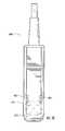
- FIG. 1Aillustrates one embodiment of an ultrasound device as disclosed herein
- FIG. 1Billustrates a side view of the base of the device of FIG. 1A ;
- FIG. 1Cillustrates a side view of the base of another embodiment of an ultrasound device as disclosed herein;
- FIG. 2illustrates a bottom view of the device of FIG. 1 ;
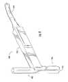
- FIG. 3illustrates one embodiment of a multi-section sterilizable shield as disclosed herein
- FIG. 4illustrates the lower section of the sterilizable shield illustrated in FIG. 3 ;
- FIG. 5Aillustrates a bottom view of the lower section of the sterilizable shield illustrated in FIG. 3 ;
- FIG. 5Billustrates a partial bottom view of another embodiment of a sterilizable shield as disclosed herein;
- FIG. 6illustrates the upper section of the sterilizable shield illustrated in FIG. 3 ;
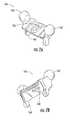
- FIGS. 7A and 7Billustrate two views of the clamping mechanism of the sterilizable shield of FIG. 3 ;
- FIG. 8illustrates one embodiment of a method for utilizing a device as disclosed herein.
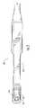
- FIG. 9illustrates an ultrasound transducer housing that can be removably attachable to a portion of a probe device defining a probe guide
- FIGS. 10A and 10Billustrate a probe device including the ultrasound transducer housing of FIG. 9 enclosed in a sterilizable shield portion, a separable portion removably attachable thereto that defines a probe guide, and a clamp removably attachable thereto, with FIG. 10A showing the sections removed from one another and FIG. 10B showing the sections when attached together.
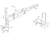
- FIG. 11illustrates another embodiment of a probe device as disclosed herein.
- FIG. 12is a side view of the probe device illustrated in FIG. 11 .
- FIG. 13is a front view of the probe device illustrated in FIG. 11 .
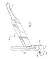
- FIG. 14illustrates the device of FIG. 11 including a removably attachable probe guide portion.
- FIG. 15is a side view of the device of FIG. 14 .
- FIG. 16is a front view of the device of FIG. 14 .
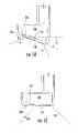
- FIG. 17illustrates the device of FIG. 14 with a clamp removably attached to the probe guide portion.
- FIG. 18is a side view of the device of FIG. 17 .
- FIG. 19is a front view of the device of FIG. 17 .
- the term “probe”generally refers to a device that can be guided to a percutaneous location, for instance for delivery of a therapeutic, e.g., a compound or a treatment, to the location; for removal of material from the location; and so forth.
- a therapeutice.g., a compound or a treatment
- the term “probe”can refer to a needle, a tube, a biopsy device, or any other item that can be guided to a percutaneous location.
- a probecan be guided by and used in conjunction with an ultrasound device as described herein.
- probe devicegenerally refers to a device that can be utilized in conjunction with a probe, but does not necessarily include the probe itself.
- disclosed hereinare devices and methods for use in guiding a percutaneous probe during a medical procedure.
- probe devicesthat can include an ultrasound transducer therein.
- Devicescan define an opening to accommodate a probe therethrough so as to improve coordination between a sonogram formed by the ultrasound device and the path of a probe passing through the opening.
- disclosed devicescan include a visualization system so as to provide a real-time image of a virtual probe on a sonogram and improve delivery of a probe to a percutaneous target.
- sterilizable shieldsthat can surround all or a portion of an ultrasound transducer to form a sterilizable probe device.
- disclosed probe devicescan be utilized in an ultrasound guided medical procedure that requires a sterile field to ensure the safety of a patient.
- disclosed devicescan be used in a central venous catheterization procedure, in a biopsy procedure, and the like.
- disclosed devicescan be formed so as to conveniently be utilized by a single operator who can control an ultrasound transducer and also deliver a probe using the probe guidance system.
- Disclosed devicescan include a variety of other beneficial features as well. For example, features of disclosed devices can improve contact and gel coupling between a skin surface and the surface of a device, can improve the effective field of the sonogram formed with the ultrasound transducer, and can prevent non-sterile use of a sterilizable shield of a device, all of which are described in greater detail herein.
- disclosed devicescan incorporate a system that can be used to visualize a percutaneous probe as it is being guided with a device.
- a visualization systemas may be incorporated with disclosed devices has been described in U.S. Pat. No. 7,244,234 to Ridley, et al., which is incorporated herein by reference. Through utilization of a visualization system, the path of a probe guided with a device and hence the location of the probe tip can be more clearly known in relation to a target imaged by the ultrasound device.
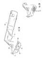
- FIG. 1Aillustrates one embodiment of an ultrasound transducer housing generally 100 .
- Transducer housing 100includes handle 102 , post 104 , and base 106 .
- FIG. 2provides a bottom view of the transducer housing 100 .
- An ultrasound transducer 120 that transmits and receives ultrasonic wavescan be located in base 106 , as shown.
- Ultrasound transducer housing 100can be formed of any suitable materials. For instance, any moldable polymeric material that can securely encase the ultrasound transducer 120 as well as contain associated electronics, wiring, switches, and the like and will not interfere with the functioning of the transducer 120 can be utilized.
- any type of ultrasound transducer as is generally known in the artcan be incorporated in transducer housing 100 .
- a piezoelectric transducer formed of one or more piezoelectric crystalline materials arranged in a two or three-dimensional arraycan be utilized.
- Such materialsgenerally include ferroelectric piezoceramic crystalline materials such as lead zirconate titanate (PZT).
- PZTlead zirconate titanate
- the elements that form the arraycan be individual electrode or electrode segments mounted on a single piezoelectric substrate, such as those described in U.S. Pat. No. 5,291,090 to Dias, which is incorporated herein by reference thereto.
- an ultrasound transducer 120can be formed of multiple elements; however, single crystal devices are also encompassed by the present disclosure.
- the use of a multiple element ultrasound transducercan be advantageous in certain embodiments, as the individual elements that make up the array can be controlled so as to limit or prevent any break or edge effects in the sonogram.
- the firing sequence of individual crystalscan be manipulated through various control systems and prevent any possible ‘blind spots’ in the sonogram as well as to clarify the edges of individual biological structures in the sonogram.
- control systemsare generally known in the art and thus will not be described in detail.
- ultrasound transducer housing 100defines a probe guide opening 126 that passes through base 106 .
- probe guide opening 126can be aligned with transducer 120 .
- a probe that is guided through the probe guide opening 126can travel on a path that is generally parallel to the scanned plane of a sonogram formed by use of the ultrasound device.
- the scanned planei.e., the plane of the sonogram
- the path of a probe guided through probe guide opening 126can be within the scanned plane. This is not a requirement of the present disclosure, however.
- the path of a probe passing through probe guide opening 126can be at an angle to the scanned plane such that it intersects the scanned plane at a point.
- the line defined by the path of a probe passing through the probe guide opening 126can be at an angle of ⁇ 1° of the scanned plane, or at a greater angle, in another embodiment.
- a line defined by the path of a probe passing through the probe guide opening 126can be at an angle of ⁇ 10, ° ⁇ 20°, ⁇ 45°, or even greater, in other embodiments.
- ultrasound transducer 120can be connected via signal wires in a cable 124 that leads to a processor that processes the data to form a sonogram on a monitor, as is generally known in the art.
- cable 124is internal to handle 102 of the ultrasound transducer housing 100 , though this particular arrangement is not a requirement of the disclosure.
- Handle 102can generally be set at an angle to post 104 of transducer housing 100 so as to be comfortably held in the hand while the device is being utilized. For instance, in the illustrated embodiment, handle 102 is about 90° to post 104 , though this angle can be varied as desired.
- a deviceneed not include an extending handle portion at all.
- base 106defines a lower surface 108 defining probe guide opening 126 and lower surface 110 from which an ultrasonic beam emitted by transducer 120 can issue.
- Surfaces 108 and 110together can form a skin contacting surface on the base 106 of the device 100 .
- surfaces 108 and 110are contiguous and angled with respect to one another.
- the angle between surface 108 and 110can vary.
- the angle marked as ⁇ in FIG. 1Bcan vary from 0 to about 30° or from about 10° to about 20° in another embodiment.
- the angle between surfaces 108 and 110can be greater than about 150° and less than 180° in one embodiment, or greater than about 160° and less than about 170° in another embodiment.
- base 106is illustrated with the edges of a scanned plane formed by ultrasound transducer 120 shown within broken lines 4 and 6 .
- the distance 8 from the termination of probe guide opening 126 to the edge 4 of the scanned planeis also shown.
- the portion of base 106 including surface 110can press into the skin of a subject somewhat and ensure good contact between the ultrasound transducer 120 , ultrasonic gel, and the skin.
- the probeUpon passing a probe through the probe guide opening 26 , the probe will contact the skin and travel the short percutaneous distance 8 before entering the ultrasound beam.
- the distance 8can depend upon the angle between the surfaces 108 and 110 , but can be relatively small. For instance, distance 8 can be less than about 25 mm, less than about 10 mm, less than about 5 mm or less than about 1 mm.
- FIG. 1Cillustrates a base 205 in which the entire bottom edge of base 205 is planar, i.e., the skin contacting surface of base 205 does not include angled portions.
- FIG. 1Calso illustrates the edges of a scanned plane formed by transducer 120 by use of broken lines 204 and 206 . As can be seen, the distance 208 between the point a probe will exit probe guide opening 226 and enter the scanned plane at 204 is greater than the distance 8 in the embodiment in FIG. 1B .
- An embodiment including a base that defines an angled bottom surface, as is illustrated in FIG. 1Bmay be preferred in those embodiments in which a percutaneous target may be close to the skin surface.
- surface 108 and/or surface 110can be curved, e.g., can define an arcuate profile along either or both of the axes of the surface.
- a curved surfacecan define a plane between the intersection line of two portions (e.g., surface 108 and surface 110 ) forming the skin contacting surface and a point at the outer edge of the curved surface. Planes defined by a curved skin contacting surface can correspond in a like manner to a planar skin contacting surface (or portions thereof) as described above.
- the skin contacting surface of a devicecan be associated with a removably cooperable material so as to encourage improved imaging of a percutaneous location.
- a planar skin contacting surfacesuch as is illustrated in FIG. 1C
- a portion of an angled skin contacting surfacesuch as surface 108 of FIG. 1B
- an ultrasound transmissive wedgeformed of an ultrasonic transmissive material so as to alter the relative orientation between the skin surface and an ultrasound device.
- a pliable saline-filled containercan be held against or attached to the base of surface 108 to alter the relative orientation of the surfaces.
- An ultrasound transmissive wedgecan be located on the skin contacting surface of a device utilizing a small amount of ultrasonic gel for a temporary attachment, or utilizing a biocompatible adhesive for a more permanent attachment, or by any other suitable adherence method.
- transducer housing 100any particular geometric configuration for transducer housing 100 and its individual sections is not essential to the present invention.
- the base 106 of transducer housing 100may be oblong, square, round, rectangular or any other suitable shape.
- the shape of ultrasound housing 100may be particularly designed to fit specific locations of the anatomy.
- ultrasound housing 100may be shaped to be utilized specifically for infraclavicular approach to the subclavian vein, approach to the internal jugular vein, specific biopsy procedures including, without limitation, breast biopsy, thyroid nodule biopsy, prostate biopsy, lymph node biopsy, and so forth, or some other specific use.
- Variations in shape for any particular applicationcan include, for example, a specific geometry for the footprint of base 106 , alteration in the size of post 104 and/or handle 102 , as well as variation in angles at which various elements of a device meet each other, such as the angle defined by the bottom of base 106 previously discussed.
- the footprint of base 106can be any suitable shape and size, e.g., rectangular, round, oblong, triangular, etc.
- the skin contacting surface of base 106can be between about 0.5 inches and about 6 inches on its greatest length.
- the footprint of base 106can be about 0.5 inches on its greatest width so as to promote stability of the device during use. In other embodiments, it can be larger, however, such as about 1 inch on its greatest width, about 2 inches on its greatest width, or even larger.
- Transducer housing 100can be used as is, with no additional shield or covering over the housing 100 .
- a probee.g., a needle
- all or a portion of transducer housing 100can be encased in a sterilizable shield, for instance in those embodiments in which a probe is intended for use in a sterile field.
- a transducer housingcan be encased in a sterilizable shield that can provide a sterile barrier between a patient and the ultrasound transducer housing 100 during a medical procedure.
- a sterilizable shieldcan generally be formed of a number of different sterilizable, biocompatible materials.
- a sterilizable shieldcan be formed of relatively inexpensive single-use materials that can be sterilized as are generally known in the art such that the entire shield can be properly disposed of following use.
- a sterilizable shieldcan be utilized multiple times, in which case it can be formed of a material that can be properly sterilized between uses.
- a sterilizable shieldcan be formed of a moldable or extrudable thermoplastic or thermoset polymeric material including, without limitation, polyethylene, polypropylene, polymethylpentene (TPX), polyester, polyvinyl chloride, polycarbonate, polystyrene, and so forth.
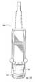
- FIG. 3illustrates one example of a sterilizable shield 130 as may be utilized to encase ultrasound transducer housing 100 .
- Sterilizable shield 130can include a lower section 132 , details of various embodiments of which are shown in FIG. 4 and FIG. 5 , and an upper section 134 , details of which are shown in FIG. 6 .
- shield section 132can include a base 136 formed of an ultrasonic transmissive material.
- Base 136can be of any suitable size and shape, but formed such that ultrasound transducer housing base 106 may be seated firmly in shield base 136 .
- a small amount of an ultrasonic gelcan be placed between the bottom surface of transducer housing base 106 and shield base 136 during seating to prevent any air between the two and promote transmission of ultrasonic waves.
- Guide post 138Arising out of shield base 136 is guide post 138 .
- Guide post 138defines at least a portion of a probe guide 139 therethrough. Probe guide 139 extends uninterrupted completely through both guide post 138 and shield base 136 .
- Guide post 138can include tabs as shown, or other formations such as hooks, insets, or the like that can be utilized to properly assemble shield base 136 about ultrasound transducer housing 100 .
- guide post 138may include a removable cap (not shown) for protection of the interior sterile surface of probe guide 139 during assembly of shield 130 with ultrasound transducer housing 100 .
- shield section 132can also include tabs 140 , 142 , 144 , etc. that can be utilized in properly seating ultrasound housing 100 within shield 130 as well as aligning shield section 132 with shield section 134 when assembling the complete shield 130 about an ultrasound transducer housing 100 .
- tabs 140 on shield section 132match corresponding notch 141 on shield section 134 shown in FIG. 6 . Together tabs 140 and notch 141 form a fastener that can secure shield section 132 and shield section 134 to one another. During assembly, tabs 140 can snap into notch 141 to securely fasten the two sections together and prevent separation of the sections 132 , 134 during use.
- a shieldcan include additional fasteners at other locations between the two sections, or can include a single fastener at an alternative location, as would be known to one of skill in the art.
- tabs 140can be simply pinched together and slid out of notch 141 .
- a single-use fastening mechanismcan be employed to secure sections of a sterilizable shield to one another.
- the tabs of the fastenerin order to disassemble a shield following use, can be permanently disabled. For instance, tabs 140 and/or notch 141 can be permanently broken away from the shield by a pulling or twisting motion, allowing the shield sections to come apart and also ensuring that the shield, which is no longer sterile, cannot be utilized again. Any method that can ensure that a fastener can only be utilized a single time may alternatively be utilized.
- the bottom of shield section 132can be seen.
- the bottom surface of base 136 of section 132includes a series of ridges 150 running along a portion of base 136 . It has been found that inclusion of such ridges on the skin-contacting surface of a device can provide benefits to disclosed devices and methods. For instance, the inclusion of ridges on the skin contacting surface can push and better hold ultrasonic gel between the device and the skin surface, preventing formation of an air gap between the two and improving coupling between a subject's skin and the device.
- ridges along the skin contacting surfacecan also add an extra pushing force against the skin itself, better holding the skin tightly against the base of the transducer, and further improving contact between the device and a subject's skin, thereby further improving coupling between the subject and the device and providing an optimal ultrasound image.
- FIG. 5Billustrates another embodiment, including a plurality of ridges 150 running across the width of the bottom surface of a base 236 of a sterilizable shield.
- ridgescan be included on the skin contacting surface of the ultrasound transducer housing itself.
- Ridges formed on the skin contacting surface of a devicecan cover the entire skin contacting surface, or only a part of the surface, as desired.
- the ridgescan cover at least a portion of the skin contacting surface through which an ultrasonic beam is transmitted, or can also cover other portions of the skin contacting surface, and in particular, that portion in the vicinity of the probe guide (e.g., on either or both surfaces 108 and 110 of FIG. 1A ).
- Ridgescan be of particular benefit on a planar skin contacting surface, such as that illustrated in FIG. 1B , so as to encourage good contact and coupling between a subject's skin, ultrasound coupling gel, and the skin contacting surface of the device.
- Ridges 150can be formed to any size and shape and of any suitable biocompatible material that can also be, in certain embodiments, a sterilizable material.
- ridgescan have a rounded or straight edge
- an individual ridgecan lie in a straight line across a skin contacting surface or can curve across the surface, they can vary in height as measured from the base surface to the top edge of the ridge
- multiple ridges on a single devicecan be identical to one another or can vary
- ridgescan be continuous over a surface or discontinuous, and so forth.
- ridges 150can be formed of the same material as other portions of a shield or transducer housing.
- the entire section 132 , including ridges 150can be injection molded from a single polymeric material.
- different portions of a sterilizable shieldcan be formed of different materials.
- ridges 150can be formed of a polymeric material that is softer than is used to form the remainder of sterilizable shield.
- a relatively soft elastomeric polymere.g., rubber, styrene-butadiene, soft polyurethanes, etc.
- ridgescan be attached to a device following formation, for instance utilizing a biocompatible adhesive as is known in the art.
- ridgescan be formed on a specifically shaped component to be attached to the base of the device.
- a series of ridgescan be formed on an ultrasound wedge as previously discussed, that can be attached either temporarily or permanently to the base of a device.
- the sterilizable shieldneed not cover the entire ultrasound transducer house.
- a sterilizable shieldcan cover just that portion of an ultrasound transducer housing from which an ultrasonic beam can be emitted.
- a shield defining one or more ridges thereoncan simply snap onto the base of an ultrasound transducer housing, covering that portion of the housing that will contact a user's skin.
- Another beneficial feature of disclosed devicescan be the geometry of a handle of a device.
- the angle at which a handle is placed on a probe devicecan be varied so as to obtain a more comfortable grip on the device while holding the transducer base tightly against the skin. Additional aspects of a can be improved as well.
- the handle of shield section 132can include a finger grip 152 that can improve the grip of a user on the device.
- additional finger gripscan be included, as desired.
- finger gripscan be provided on a handle such that the handle is specifically designed for left-handed or right-handed use.
- Sterilizable shield 130also includes section 134 , illustrated in FIG. 6 .
- Section 134can be removably attached to section 132 to enclose an ultrasound transducer housing 100 , as previously discussed.
- Section 134defines the terminal portion 151 of probe guide 139 in portion 160 .
- Terminal portion 151is sized so as to snugly reside over the top of guide post 138 of section 132 and form uninterrupted probe guide 139 extending from the top surface of portion 160 of section 134 to the bottom surface of base 136 of section 132 .
- a sterilizable shield as disclosed hereinis not limited to two completely separable portions.
- a sterilizable shieldcan be hinged and/or can include additional portions, as desired.
- a sterilizable shieldcan be formed of two, three, or more separable sections that can be assembled to enclose all or a portion of an ultrasound housing and form a sterile barrier between the enclosed housing and an exterior field.
- a sterilizable shieldcan be of a unitary construction.
- a sterilizable shieldcan be of a pliant material that can enclose all or a portion of an ultrasound housing and form a sterile barrier between the enclosed housing and an exterior field.
- ultrasound transducer housing 100 defining probe guide opening 126can be seated in shield base 136 of section 132 such that guide post 138 extends through transducer housing probe guide opening 126 .
- tabs on guide post 138can slide or snap into recesses of probe guide opening 126 (not shown), helping to properly seat transducer housing 100 in section 132 .
- section 134can be aligned with section 132 and fastened into place to cover the top of transducer housing 100 .
- a protective capcovers the end of guide post 138 , it can be removed during assembly and maintain the sterility of the interior of the probe guide 139 throughout the assembly process.
- Tabs 140can snap or slide into recesses notch 141 to fasten and secure section 132 and 134 together.
- probe guide 139can extend continuously from the top of portion 160 of shield portion 134 through the shield base 136 . Moreover, and of great benefit to the device, probe guide 139 can be sterile and within the probe guide opening 126 of ultrasound transducer housing 100 .
- a probeto remain at the subcutaneous target for a period of time following insertion of a probe.
- a cannulated needle attached to a syringeis first guided into a vein. After the needle tip is in the lumen of the vein, the needle is held in place while a guide wire is fed down through the needle and into the vein. During this process, only a slight movement of the needle can cause the needle tip to move out of the vein, and the entire procedure must be repeated.
- a devicecan include a clamp that can firmly hold a probe in the probe device and prevent motion of the probe during subsequent procedures such as catheter insertion, biopsy procedures, fluid aspiration, or the like. Motion of the percutaneous probe tip can be much less likely when the probe is securely clamped to the probe device and the probe device is in turn held and stabilized by pressing against the subject's skin surface as compared to when only the probe itself is held without clamping to the larger probe device.
- FIG. 3One embodiment of a clamp for use with disclosed probe devices can be seen in FIG. 3 .
- a probe 154can extend through the probe guide of sterilizable shield 130 .
- Clamp 156sits atop shield section 134 such that probe 154 passes through clamp aperture 158 as shown.
- Aperture 158includes a wide portion and a narrow portion and defines a clamping surface.
- the wide portioncan be of a size such that a probe can pass freely through the wide portion without hindrance.
- Aperture 158can gradually narrow from the wide portion of the aperture to form the narrow portion extending to a tip.
- the clampwhen a probe is located in the wide portion of aperture 158 , the clamp can be slid, rotated, or otherwise moved in relation to the probe such that the clamping portion of the clamp crosses the axis of the probe and a clamping surface of the clamp, e.g., a surface of aperture 158 at the narrow portion, can contact the probe and the probe can become tightly trapped in the narrow portion of the aperture 158 as the width of the narrow portion of aperture 158 decreases.
- a clamping surface of the clampe.g., a surface of aperture 158 at the narrow portion
- a clamping surfacecan force a probe against the wall of the probe guide to secure the probe in place.
- a clamping surfacecan be set on a clamp and at an angle with reference to the probe guide.
- the clamping surface of the clampneed not be one side of an aperture defined by the clamp, but may be, by way of example, an outer edge of a clamp section, with no opposing piece on the clamp.
- a clampcan be formed of any biocompatible, sterilizable material.
- at least that portion of a clamp that defines a clamping surfacecan be formed of a material that is harder than a probe to be held by the clamp, for example a hard polymer or a stainless steel.
- the clamping surface(s)can cut into the surface of a probe, providing additional holding power in addition to the friction hold provided by trapping the clamp with the clamping surface(s).
- a clamp, and particularly a clamping surface of a clampcan be formed of a material that is softer than a probe held in the clamp.
- a clampcan be formed of a relatively soft polymer such as soft polyurethane or other biocompatible polymeric material.
- the clamping surface(s)can deform somewhat as a probe is forced against the clamping surface. The deformation of a clamping surface about a probe can increase the force on the probe, more securely holding the probe in place in the clamp.
- a clampcan define additional features that can improve its holding ability.
- a clamping surfacecan define a series of serrations. Upon contact between a probe and the clamping surface, the serrations of the edges can provide increased surface area for contact between the clamp and the probe, improving hold between the two.
- serrations on the surface of the clamping surfacecan cut into the surface of the probe at the points of contact, further improving hold between the two.
- clamp 156includes formations 162 , 163 that can be used to move clamp 156 and trap probe 154 in the aperture 158 as previously discussed.
- a sterilized shield 130can be held against the skin surface of a subject and the user can move the clamp 156 with his/her thumb to force the probe into the narrow section of aperture 158 and firmly clamp the probe 154 in place.
- clamp 156includes two formations 162 , 163 , one on either side of clamp 156 such that the clamp can be operated while held in either the right or left hand of a user.
- clamp 156can include only a single formation, for instance in those embodiments in which a probe device is designed for only right-handed or left-handed use, or alternatively, when the single formation can be accessed from either side of the device.
- the shape of the formations 162 , 163can be any shape that can be accessed by a user and can be pushed, pulled, twisted or otherwise activated to move a clamp and tightly grip a probe in a probe guide.
- a formationcan be round, as illustrated, or can be a flat, paddle-shaped formation, a post, or any other convenient shape.
- any formationcan be utilized to aid in moving the clamp to force a clamping surface against a probe.
- a clampcan define an indentation to be used in moving a clamp.
- a clampcan define a rough tactility at a location that can aid in moving the clamp with a thumb or finger. Equivalent or alternative formations would be obvious to one of ordinary skill in the art.
- a portion of the clampcan be rotated so as to force the clamping surface of the clamp against a probe held in the probe guide.
- a probe clampas is illustrated in U.S. Pat. No. 7,244,234 to Ridley, et al., previously incorporated by reference, can be utilized in conjunction with disclosed devices.
- clamp 156is attached to shield 130 at a pivot point.
- tabs 164 of clamp 156can fit into recesses 165 formed in the lower section 132 of sterilizable shield 130 (see, e.g., FIG. 5A ).
- clamp 156can rotate about the pivot point of tabs 164 and over the rounded upper surface of portion 160 of upper section 134 such that the clamping portion, i.e., that portion of clamp 156 that defines the aperture 158 crosses the axis of the probe 154 to lock the probe in place.
- a clampabout a pivot to secure a probe is not a requirement of disclosed clamps.
- the entire clampcan slide laterally across a portion of a probe device, e.g., a shield or a transducer housing, to clamp a probe in place.
- a probe devicee.g., a shield or a transducer housing
- any motion of all or a portion of a clamp that can be controlled by a user and can grip a probe as describedis encompassed in the present disclosure.
- a projectioncan be moved in the opposite direction as was used to clamp the probe, freeing the probe.
- FIG. 9illustrates another embodiment of an ultrasound transducer housing 800 that can be removably attached to a sterilizable shield.
- ultrasound transducer housing 800can include a handle 802 , a post 804 , and a base 806 .
- Ultrasound transducer housing 800also defines a lower surface 810 , as shown. In this particular embodiment, however, the ultrasound transducer housing does not include a probe guide opening. Instead, ultrasound transducer housing 800 is removably attachable to a second portion of a device that defines a probe guide opening.
- ultrasound transducer housing 800can be utilized in conjunction with a sterilizable shield that defines the probe guide.
- the sterilizable shieldcan be formed of single or multiple removably attachable pieces.
- FIGS. 10A and 10Billustrate one embodiment of a sterilizable shield 930 that can be used in conjunction with an ultrasound device 800 illustrated in FIG. 8 .
- sterilizable shield 930can be formed of multiple attachable pieces.
- sterilizable shield 930includes section 932 and section 961 that defines a probe guide for passage of a probe therethrough. Accordingly, section 961 can alternatively be referred to as a probe guide portion.
- section 932can be separable into two or more sections, as illustrated for device 230 of FIGS. 3-6 .
- Section 961can also include clamp 956 defining aperture 958 and formations 962 , 963 that rotates about pivot 964 for clamping probe 954 in the probe guide.
- section 961can be attached to shield 932 , for instance by use of aligned tabs and notches, and so forth, so as to attach the probe guide portion to the sterilizable shield, as shown in FIG. 10B .
- an ultrasound transducer housing that does not define a probe guide openingcan be removably attached to a probe guide portion that can define a probe guide opening and include the clamp, without enclosing all or a portion of the ultrasound transducer housing in a shield.
- a sterilizable shield portioncan cover only the skin contacting surface of a device.
- a shield portioncan snap onto the base of a device.
- all or a portion of a sterilizable shieldcan be formed of a pliant material that can enclose an ultrasound transducer housing.
- a probe guide portioncan be indirectly attached to the pliant sterilizable shield portion, for instance by use of a frame or other attachment device that is on the pliant material or optionally on the ultrasound transducer housing itself, such that the pliant material of the shield is held between the frame and the probe guide portion.
- FIG. 11Yet another embodiment is illustrated in FIG. 11 .
- a device 1000need not include a separate handle portion. Such a device can be comfortably held by the rounded back portion 1002 , while holding the angled skin contacting surface 1110 against a subject.
- a side view of device 1000 shown in FIG. 12better illustrates the angle of skin contacting surface 1110 .
- a deviceneed not include an angle in the skin contacting surface, and in another embodiment the skin contacting surface of a device can be flat with no angle as is shown for the device of FIG. 11 , or arcuate.
- FIG. 13A front view of device 1000 is shown in FIG. 13 .
- device 1000includes attachment slots 1004 , 1006 on either side of the device. These attachment slots 1004 , 1006 can be utilized to attach another portion to device 1000 .
- FIG. 14illustrates device 1000 including a probe guide portion 1061 attached to device 1000 via slots 1004 , 1006 .
- probe guide portion 1061can, in one embodiment, be attached such that probe guide 1039 is aligned with an ultrasound transducer located in the base of device 1000 .
- device 1000need not include an ultrasound transducer in the base.
- FIG. 15illustrates a side view of device 1000 including probe guide portion 1061 attached thereto.
- probe guide portion 1061can define skin contacting surface 1008 and device 1000 can device skin contacting surface 1010 , with the two surfaces 1008 , 1010 held at an angle to one another to promote improved contact between a device and a subject, as previously discussed.
- FIG. 16is a front view of the embodiment illustrated in FIGS. 14 and 15 .
- all or a portion of device 1000can be covered or encased with a sterilizable shield.
- all of the body 1000 of the devicecan be encased in a sterilizable shield, and the probe guide portion 1061 can then be attached to the sterilizable shield.
- one a portion of the devicefor instance the skin contacting portion, can be covered by a sterilizable shield.
- the probe guide portion 1061can be sterile, and the portion 1000 can be nonsterile.
- a probe guide portionneed not include a skin contacting surface.
- a separably removable probe guide portioncan be attached to a device such that the base of the probe guide portion will be above and not contacting the skin of a subject.
- contact between a subject and a devicewill only be between the body of a device that encompasses the ultrasound transducer.
- the skin contacting surfacecan be at the surface from which an ultrasonic beam is emitted, and the probe guide portion can be aligned with the transducer, but held above the skin contacting surface of the body of the device.
- a probe passing through a probe guidewill exit the probe guide and pass for a distance through the surrounding air prior to contacting the skin of a subject and passing therethrough.
- a probe guidecan be defined between a probe guide portion 1061 and the side of device 1000 .
- a probe guide portioncan define a V-shaped notch, a slot, a semi-circular cut out or the like in the side of the probe guide portion that will contact the device 1000 .
- the probe guidecan be completely formed.
- the side of the body of the devicecan also define a portion of a probe guide, in one embodiment, and the probe guide can be formed between the two removably attachable portions of the device.
- a probe guide portioncan also be formed of multiple removably attachable pieces, if desired.
- FIG. 17illustrates the device 1000 following attachment of a clamp 1056 to the probe guide portion 1061 .
- FIG. 17illustrates this embodiment in a side view and
- FIG. 18illustrates this embodiment in a front view.
- a devicecan be held against the skin and a probe can be passed through the probe guide.
- the clamp 1056can be activated, for instance by the user pulling formation 1063 from the unclamped to the clamped position.
- a probe tipcan be guided to a percutaneous target on a line that is parallel to the plane imaged on a sonogram formed by use of an ultrasound transducer incorporated in a device.
- the probe tipcan travel on a path that defines a line that is coincident in the scanned plane, is parallel to the scanned plane, or intersects the scanned plane at a point.
- the path of the probe to the targetcan be known, even if it cannot be discerned on the sonogram: the probe will advance toward the target on a straight line and at a predetermined angular relationship to the ultrasound housing base from the probe guide opening to the target that is imaged by the ultrasound.
- the path of the probe and the scanned plane of the sonogram imagecan both be defined by the orientation of the transducer and can be coordinated on the target. In order to strike the target, the probe can be merely guided along this known path the desired distance.
- the probe itselfcan be visualized on the scanned plane.
- the probecan be seen in the sonogram, depending on the density of surrounding tissue and other process parameters.
- the probeeven if the path of the probe is coincident with the scanned plane, the probe itself may not be visible on the sonogram, but artifacts of the passage of the probe can be visualized, e.g., shadows, motions of internal structures as the probe passes, and so forth.
- the known path of the probecan be added to the sonogram, and the targeting procedures can be even further simplified.
- one embodimentincludes the addition of a targeting line on the sonogram extending from that point on the sonogram where the probe guide opening exits the housing (or passes the transducer) and projecting across the ultrasonic field in a straight line at the known angle.
- this targeting lineis made to intersect the target that is imaged by the device, the operator can be confident that the probe is accurately directed to the target.
- other targeting informationcan be displayed on the sonogram. For example, in one embodiment, information showing the approach of the probe to the target can be displayed.
- a motion detectorcan register motion of a probe in the probe guide, and that information can be displayed, for instance, as a real time image of the probe on a screen or monitor.
- the location of the probe tip in relation to the target and the moment when the probe tip strikes the targetcan be seen in real time by an operator watching the virtual probe on the monitor during the procedure.
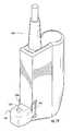
- FIG. 8illustrates one embodiment of the presently disclosed subject matter during use in which an image of a virtual probe may be overlaid on a sonogram.
- the probe devicecan include a detector 170 located in the post of the sterilizable shield or in the post of the transducer housing. Detector 170 can recognize and monitor the movement of probe 154 as it passes through probe guide and into a subject. Information from detector 170 and the ultrasound transducer can pass through cable 124 to monitor 174 . The probe 154 can then be imaged on a monitor 174 as probe image 178 . The monitor 174 can also show the internal target, for instance a blood vessel 176 .
- detector 170can utilize infrared (IR), ultrasound, optical, laser, magnetic or other motion detection mechanisms.
- IRinfrared
- the location of detector 170is not critical to the invention. In the embodiment illustrated in FIG. 8 , detector 170 is located in the post of either the shield 130 or the ultrasound transducer housing enclosed within the shield 130 . In other embodiments, however, the detector may be located elsewhere in the system including, for example, on a portion of the probe itself.
- Signals from detector 170can create a data stream which can be sent to a processor.
- a processing unitcan be internal or external to the hand-held device. For example, data from detector 170 can be sent to a standard lap top or desk top computer processor or part of a self-contained ultrasound system as is known in the art.
- a processorcan be loaded with suitable recognition and analysis software and can receive and analyze the stream of data from detector 170 .
- the processing unitcan also include standard imaging software as is generally known in the art to receive data from the ultrasound transducer via cable 124 .
- Probe 154can be of a predetermined length which can be input data entered into a processor by the user or can be preprogrammed into the system as default data.
- a processorcan be programmed to calculate the relative position of the probe tip in relation to the ultrasound transducer 120 , in relation to detector 170 , in relation to the exit of the probe guide, or to any other convenient reference point.
- a processorcan communicate this position information digitally to monitor 174 and the information can be displayed on the monitor such as in a numerical format or optionally as a real time image of a virtual probe 178 shown in conjunction with the sonogram including an image 176 of the target, such as a blood vessel.
- disclosed devicescan be utilized to actually show the approach of the probe toward the target on the monitor throughout the entire procedure.
- disclosed devicescan be utilized to ensure the probe tip remains at the target during subsequent procedures. For example, in those embodiments wherein the detector 170 monitors the motion of the probe 154 , as long as probe 154 remains ‘visible’ to detector 170 , the image 176 of probe 154 can remain on the monitor 174 . Thus, any motion of the probe tip in relation to the target can be noted by an observer.
- ultrasound guided probe devices and methodsmay be utilized in many different medical procedures.
- Exemplary applications for the devicescan include, without limitation
- Some of these exemplary procedureshave employed the use of ultrasound in the past, and all of these procedures, as well as others not specifically listed, could utilize the disclosed ultrasound guided devices to improve procedural safety as well as patient safety and comfort, in addition to provide more economical use of ultrasound devices.
- the presently disclosed devicesmay be utilized with standard probe kits already available on the market.
Landscapes
- Health & Medical Sciences (AREA)
- Life Sciences & Earth Sciences (AREA)
- Surgery (AREA)
- Medical Informatics (AREA)
- Veterinary Medicine (AREA)
- Pathology (AREA)
- Nuclear Medicine, Radiotherapy & Molecular Imaging (AREA)
- Engineering & Computer Science (AREA)
- Biomedical Technology (AREA)
- Heart & Thoracic Surgery (AREA)
- Physics & Mathematics (AREA)
- Molecular Biology (AREA)
- Public Health (AREA)
- Animal Behavior & Ethology (AREA)
- General Health & Medical Sciences (AREA)
- Biophysics (AREA)
- Radiology & Medical Imaging (AREA)
- Acoustics & Sound (AREA)
- Ultra Sonic Daignosis Equipment (AREA)
- Surgical Instruments (AREA)
Abstract
Description
- Central Venous Catheterization
- Cardiac Catheterization (Central Arterial Access)
- Dialysis Catheter Placement
- Breast Biopsies
- Paracentesis
- Pericardiocentesis
- Thoracentesis
- Arthrocentesis
- Lumbar Puncture
- Epidural Catheter Placement
- Peripherally Inserted Central Catheter (PICC) line placement
- Thyroid Nodule Biopsies
- Cholecystic Drain Placement
- Amniocentesis
- Regional Anesthesia—Nerve Block
Claims (16)
Priority Applications (11)
| Application Number | Priority Date | Filing Date | Title |
|---|---|---|---|
| US12/576,487US8761862B2 (en) | 2009-10-09 | 2009-10-09 | Ultrasound guided probe device and sterilizable shield for same |
| JP2012533153AJP2013507178A (en) | 2009-10-09 | 2010-08-26 | Ultrasonic device for guiding a probe and sterilizable shield for the device |
| EP10749731AEP2485649A2 (en) | 2009-10-09 | 2010-08-26 | Ultrasound device for probe guidance and sterilizable shield for same |
| EP13152351.6AEP2586376B1 (en) | 2009-10-09 | 2010-08-26 | Ultrasound device for probe guidance and sterilizable shield for same |
| CA2776959ACA2776959A1 (en) | 2009-10-09 | 2010-08-26 | Ultrasound device for probe guidance and sterilizable shield for same |
| AU2010303831AAU2010303831B2 (en) | 2009-10-09 | 2010-08-26 | Ultrasound device for probe guidance and sterilizable shield for same |
| PCT/US2010/046756WO2011043875A2 (en) | 2009-10-09 | 2010-08-26 | Ultrasound device for probe guidance and sterilizable shield for same |
| US13/919,433US20130281837A1 (en) | 2009-10-09 | 2013-06-17 | Ultrasound Device for Probe Guidance and Sterilizable Shield for Same |
| JP2014138312AJP5628457B2 (en) | 2009-10-09 | 2014-07-04 | Medical probe device and method for visualizing a probe |
| JP2014263821AJP2015107336A (en) | 2009-10-09 | 2014-12-26 | Medical probe device and method for visualizing probe |
| US14/680,424US9351704B2 (en) | 2009-10-09 | 2015-04-07 | Ultrasound device for probe guidance and sterilizable shield for same |
Applications Claiming Priority (1)
| Application Number | Priority Date | Filing Date | Title |
|---|---|---|---|
| US12/576,487US8761862B2 (en) | 2009-10-09 | 2009-10-09 | Ultrasound guided probe device and sterilizable shield for same |
Related Child Applications (1)
| Application Number | Title | Priority Date | Filing Date |
|---|---|---|---|
| US13/919,433DivisionUS20130281837A1 (en) | 2009-10-09 | 2013-06-17 | Ultrasound Device for Probe Guidance and Sterilizable Shield for Same |
Publications (2)
| Publication Number | Publication Date |
|---|---|
| US20110087105A1 US20110087105A1 (en) | 2011-04-14 |
| US8761862B2true US8761862B2 (en) | 2014-06-24 |
Family
ID=43347951
Family Applications (3)
| Application Number | Title | Priority Date | Filing Date |
|---|---|---|---|
| US12/576,487Active2032-11-22US8761862B2 (en) | 2009-10-09 | 2009-10-09 | Ultrasound guided probe device and sterilizable shield for same |
| US13/919,433AbandonedUS20130281837A1 (en) | 2009-10-09 | 2013-06-17 | Ultrasound Device for Probe Guidance and Sterilizable Shield for Same |
| US14/680,424ActiveUS9351704B2 (en) | 2009-10-09 | 2015-04-07 | Ultrasound device for probe guidance and sterilizable shield for same |
Family Applications After (2)
| Application Number | Title | Priority Date | Filing Date |
|---|---|---|---|
| US13/919,433AbandonedUS20130281837A1 (en) | 2009-10-09 | 2013-06-17 | Ultrasound Device for Probe Guidance and Sterilizable Shield for Same |
| US14/680,424ActiveUS9351704B2 (en) | 2009-10-09 | 2015-04-07 | Ultrasound device for probe guidance and sterilizable shield for same |
Country Status (6)
| Country | Link |
|---|---|
| US (3) | US8761862B2 (en) |
| EP (2) | EP2586376B1 (en) |
| JP (3) | JP2013507178A (en) |
| AU (1) | AU2010303831B2 (en) |
| CA (1) | CA2776959A1 (en) |
| WO (1) | WO2011043875A2 (en) |
Cited By (24)
| Publication number | Priority date | Publication date | Assignee | Title |
|---|---|---|---|---|
| US10178984B2 (en) | 2014-01-10 | 2019-01-15 | Soma Research, Llc | Needle guidance systems for use with ultrasound devices |
| US10231643B2 (en) | 2009-06-12 | 2019-03-19 | Bard Access Systems, Inc. | Apparatus and method for catheter navigation and tip location |
| US10231753B2 (en) | 2007-11-26 | 2019-03-19 | C. R. Bard, Inc. | Insertion guidance system for needles and medical components |
| US10238418B2 (en) | 2007-11-26 | 2019-03-26 | C. R. Bard, Inc. | Apparatus for use with needle insertion guidance system |
| US10271762B2 (en) | 2009-06-12 | 2019-04-30 | Bard Access Systems, Inc. | Apparatus and method for catheter navigation using endovascular energy mapping |
| US10349857B2 (en) | 2009-06-12 | 2019-07-16 | Bard Access Systems, Inc. | Devices and methods for endovascular electrography |
| US10349890B2 (en) | 2015-06-26 | 2019-07-16 | C. R. Bard, Inc. | Connector interface for ECG-based catheter positioning system |
| US10449330B2 (en) | 2007-11-26 | 2019-10-22 | C. R. Bard, Inc. | Magnetic element-equipped needle assemblies |
| US10524691B2 (en) | 2007-11-26 | 2020-01-07 | C. R. Bard, Inc. | Needle assembly including an aligned magnetic element |
| US10602958B2 (en) | 2007-11-26 | 2020-03-31 | C. R. Bard, Inc. | Systems and methods for guiding a medical instrument |
| US10751509B2 (en) | 2007-11-26 | 2020-08-25 | C. R. Bard, Inc. | Iconic representations for guidance of an indwelling medical device |
| US10849695B2 (en) | 2007-11-26 | 2020-12-01 | C. R. Bard, Inc. | Systems and methods for breaching a sterile field for intravascular placement of a catheter |
| US10863920B2 (en) | 2014-02-06 | 2020-12-15 | C. R. Bard, Inc. | Systems and methods for guidance and placement of an intravascular device |
| US10966630B2 (en) | 2007-11-26 | 2021-04-06 | C. R. Bard, Inc. | Integrated system for intravascular placement of a catheter |
| US10973584B2 (en) | 2015-01-19 | 2021-04-13 | Bard Access Systems, Inc. | Device and method for vascular access |
| US10992079B2 (en) | 2018-10-16 | 2021-04-27 | Bard Access Systems, Inc. | Safety-equipped connection systems and methods thereof for establishing electrical connections |
| US11000207B2 (en) | 2016-01-29 | 2021-05-11 | C. R. Bard, Inc. | Multiple coil system for tracking a medical device |
| US11027101B2 (en) | 2008-08-22 | 2021-06-08 | C. R. Bard, Inc. | Catheter assembly including ECG sensor and magnetic assemblies |
| US11134915B2 (en) | 2007-11-26 | 2021-10-05 | C. R. Bard, Inc. | System for placement of a catheter including a signal-generating stylet |
| US11207496B2 (en) | 2005-08-24 | 2021-12-28 | C. R. Bard, Inc. | Stylet apparatuses and methods of manufacture |
| US11413429B2 (en) | 2016-06-01 | 2022-08-16 | Becton, Dickinson And Company | Medical devices, systems and methods utilizing permanent magnet and magnetizable feature |
| US11826522B2 (en) | 2016-06-01 | 2023-11-28 | Becton, Dickinson And Company | Medical devices, systems and methods utilizing permanent magnet and magnetizable feature |
| US11877839B2 (en) | 2016-06-01 | 2024-01-23 | Becton, Dickinson And Company | Invasive medical devices including magnetic region and systems and methods |
| US12303324B2 (en) | 2018-05-31 | 2025-05-20 | Faction Imaging Inc. | Method of medical imaging using multiple arrays |
Families Citing this family (28)
| Publication number | Priority date | Publication date | Assignee | Title |
|---|---|---|---|---|
| US7794407B2 (en) | 2006-10-23 | 2010-09-14 | Bard Access Systems, Inc. | Method of locating the tip of a central venous catheter |
| US8388546B2 (en) | 2006-10-23 | 2013-03-05 | Bard Access Systems, Inc. | Method of locating the tip of a central venous catheter |
| US9636031B2 (en) | 2007-11-26 | 2017-05-02 | C.R. Bard, Inc. | Stylets for use with apparatus for intravascular placement of a catheter |
| US8849382B2 (en) | 2007-11-26 | 2014-09-30 | C. R. Bard, Inc. | Apparatus and display methods relating to intravascular placement of a catheter |
| US8437833B2 (en) | 2008-10-07 | 2013-05-07 | Bard Access Systems, Inc. | Percutaneous magnetic gastrostomy |
| JP5795576B2 (en) | 2009-06-12 | 2015-10-14 | バード・アクセス・システムズ,インコーポレーテッド | Method of operating a computer-based medical device that uses an electrocardiogram (ECG) signal to position an intravascular device in or near the heart |
| BR112013002431B1 (en) | 2010-08-20 | 2021-06-29 | C.R. Bard, Inc | SYSTEM FOR RECONFIRMING THE POSITION OF A CATHETER INSIDE A PATIENT |
| US8425425B2 (en) | 2010-09-20 | 2013-04-23 | M. Dexter Hagy | Virtual image formation method for an ultrasound device |
| US8801693B2 (en) | 2010-10-29 | 2014-08-12 | C. R. Bard, Inc. | Bioimpedance-assisted placement of a medical device |
| RU2609203C2 (en) | 2011-07-06 | 2017-01-30 | Си.Ар. Бард, Инк. | Determination and calibration of needle length for needle guidance system |
| ES2568225T3 (en) | 2011-09-06 | 2016-04-28 | Ezono Ag | Imaging probe and method to obtain position and / or orientation information |
| GB201303917D0 (en) | 2013-03-05 | 2013-04-17 | Ezono Ag | System for image guided procedure |
| US20140275990A1 (en) | 2013-03-15 | 2014-09-18 | Soma Access Systems, Llc | Ultrasound Guidance System Including Tagged Probe Assembly |
| US9918738B2 (en)* | 2013-03-29 | 2018-03-20 | Fukuoka University | Ultrasound-guided puncture assist device and ultrasound-guided puncture method using the same |
| US9649161B2 (en)* | 2014-01-21 | 2017-05-16 | Choon Kee Lee | Stereotactic positioning guide apparatus |
| BR112018008778A2 (en)* | 2015-10-29 | 2018-10-30 | Avent Inc | ultrasound imaging system, ultrasound imaging probe and method of ultrasound imaging during a nerve block procedure |
| WO2018057940A1 (en) | 2016-09-22 | 2018-03-29 | Kusumoto Walter | Pericardiocentesis needle guided by cardiac electrophysiology mapping |
| US11007016B2 (en) | 2016-09-22 | 2021-05-18 | Walter Kusumoto | Intracardiac ultrasound catheter handheld adapter |
| US11382566B1 (en) | 2016-11-21 | 2022-07-12 | Walter Kusumoto | Lead placement assisted by electrophysiology mapping |
| WO2019165202A1 (en)* | 2018-02-22 | 2019-08-29 | Kusumoto Walter | Intracardiac ultrasound catheter handheld adapter |
| JP7186021B2 (en)* | 2018-06-15 | 2022-12-08 | フクダ電子株式会社 | Auxiliary member for ultrasonic probe |
| HUE070852T2 (en)* | 2019-11-12 | 2025-07-28 | Oculus Optikgeraete Gmbh | Method and apparatus for providing sterile cover for non-contact fundus viewing device |
| CN111528915B (en)* | 2020-06-05 | 2022-11-29 | 济宁市第二人民医院 | A portable multi-probe ophthalmic ultrasonic diagnostic device |
| CH718941A2 (en) | 2021-09-02 | 2023-03-15 | Compremium Ag | Interchangeable attachment for an ultrasound probe, boxed attachment and ultrasound probe. |
| CN113940759B (en)* | 2021-09-26 | 2024-05-24 | 武汉联影智融医疗科技有限公司 | Puncture operation master control table and puncture robot |
| AU2023388175A1 (en)* | 2022-12-07 | 2025-06-12 | Veintech Pty Ltd | A cover for an acoustic medical device |
| CN118303920B (en)* | 2024-06-07 | 2024-08-02 | 北京迈迪斯医疗技术有限公司 | Buckle assembly for intraoperative ultrasonic probe, ultrasonic probe assembly and puncture system |
| CN118303921B (en)* | 2024-06-07 | 2024-08-02 | 北京迈迪斯医疗技术有限公司 | Buckle connection structure for ultrasonic probe, ultrasonic probe assembly and puncture system |
Citations (116)
| Publication number | Priority date | Publication date | Assignee | Title |
|---|---|---|---|---|
| US3721227A (en) | 1971-08-24 | 1973-03-20 | Nulty D Mc | Transducer for pulse-echo ultrasonic exploration |
| US3968565A (en) | 1972-09-01 | 1976-07-13 | U.S. Philips Corporation | Method of manufacturing a device comprising a semiconductor body |
| US3983474A (en) | 1975-02-21 | 1976-09-28 | Polhemus Navigation Sciences, Inc. | Tracking and determining orientation of object using coordinate transformation means, system and process |
| US4029084A (en) | 1974-12-23 | 1977-06-14 | Siemens Aktiengesellschaft | Ultrasound applicator with guide slot for puncturing cannula |
| US4044273A (en) | 1974-11-25 | 1977-08-23 | Hitachi, Ltd. | Ultrasonic transducer |
| US4054881A (en) | 1976-04-26 | 1977-10-18 | The Austin Company | Remote object position locater |
| US4108165A (en) | 1977-06-20 | 1978-08-22 | Krautkramer-Branson, Incorporated | Transducer probe for pulse-echo ultrasonic exploration |
| US4249539A (en) | 1979-02-09 | 1981-02-10 | Technicare Corporation | Ultrasound needle tip localization system |
| US4289139A (en) | 1978-02-22 | 1981-09-15 | Tokyo Shibaura Denki Kabushiki Kaisha | Ultrasonic transducer probe |
| DE2942405C2 (en) | 1979-10-19 | 1983-09-08 | Siemens AG, 1000 Berlin und 8000 München | Device for puncturing internal organs, vessels or the like. |
| US4407294A (en) | 1982-01-07 | 1983-10-04 | Technicare Corporation | Ultrasound tissue probe localization system |
| EP0102800A2 (en) | 1982-09-02 | 1984-03-14 | Advanced Technology Laboratories, Inc. | Needle guide for use with medical ultrasonic scanning apparatus |
| US4491137A (en) | 1982-08-17 | 1985-01-01 | Tokyo Shibaura Denki Kabushiki Kaisha | Adaptor for ultrasonic transducer probe |
| US4608989A (en) | 1983-02-07 | 1986-09-02 | Medical Innovation Company A/S | Stand-off cell for an ultrasonic scanner head |
| US4635644A (en) | 1984-07-24 | 1987-01-13 | Hitachi Medical Corporation | Ultrasonic applicator |
| US4671292A (en) | 1985-04-30 | 1987-06-09 | Dymax Corporation | Concentric biopsy probe |
| US4681103A (en) | 1985-03-11 | 1987-07-21 | Diasonics, Inc. | Ultrasound guided surgical instrument guide and method |
| US4742829A (en) | 1986-08-11 | 1988-05-10 | General Electric Company | Intracavitary ultrasound and biopsy probe for transvaginal imaging |
| US4838506A (en) | 1988-06-15 | 1989-06-13 | Cooper William I | Guidance device for ultrasound guided surgical procedures |
| US4899756A (en) | 1988-07-18 | 1990-02-13 | Sonek Jiri D | Articulated needle guide for ultrasound imaging and method of using same |
| US5078144A (en) | 1988-08-19 | 1992-01-07 | Olympus Optical Co. Ltd. | System for applying ultrasonic waves and a treatment instrument to a body part |
| US5119818A (en) | 1990-07-25 | 1992-06-09 | Care Wise Medical Products Corporation | Radiation detecting biopsy probe |
| US5261409A (en) | 1991-05-27 | 1993-11-16 | Sulzer Brothers Limited | Puncturing device for blood vessels |
| US5285154A (en) | 1991-10-15 | 1994-02-08 | Eldec Corporation | Saturable core proximity sensor aligned perpendicular to a magnet target having a plate and a non-magnetic metal housing |
| US5291090A (en) | 1992-12-17 | 1994-03-01 | Hewlett-Packard Company | Curvilinear interleaved longitudinal-mode ultrasound transducers |
| US5329927A (en) | 1993-02-25 | 1994-07-19 | Echo Cath, Inc. | Apparatus and method for locating an interventional medical device with a ultrasound color imaging system |
| US5341810A (en) | 1991-10-29 | 1994-08-30 | Sulzer Medizinaltechnik Ag | Sterile puncturing device for blood vessels with a non-sterile ultrasound probe, and apparatus for preparing the device |
| US5351004A (en) | 1991-10-15 | 1994-09-27 | Eldec Corporation | Saturable core proximity sensor including a flux director and a magnetic target element |
| EP0617922A1 (en) | 1993-04-01 | 1994-10-05 | Armin Bollinger | Doppler ultrasound probe with needle guide |
| US5490522A (en) | 1993-01-18 | 1996-02-13 | Dardel; Eric | Device for locating and puncturing blood vessels |
| US5494039A (en) | 1993-07-16 | 1996-02-27 | Cryomedical Sciences, Inc. | Biopsy needle insertion guide and method of use in prostate cryosurgery |
| US5647373A (en) | 1993-11-07 | 1997-07-15 | Ultra-Guide Ltd. | Articulated needle guide for ultrasound imaging and method of using same |
| US5758650A (en) | 1996-09-30 | 1998-06-02 | Siemens Medical Systems, Inc. | Universal needle guide for ultrasonic transducers |
| US5871448A (en) | 1997-10-14 | 1999-02-16 | Real World Design And Development Co. | Stepper apparatus for use in the imaging/treatment of internal organs using an ultrasound probe |
| US5879297A (en) | 1997-05-08 | 1999-03-09 | Lucent Medical Systems, Inc. | System and method to determine the location and orientation of an indwelling medical device |
| US5924992A (en) | 1997-11-26 | 1999-07-20 | Acuson Corporation | Semi-compliant needle guide for use with ultrasound transducers |
| US5928219A (en) | 1998-09-29 | 1999-07-27 | Siemens Medical Systems, Inc. | Fail-safe needle guide mount for ultrasonic probes |
| US5941889A (en) | 1997-10-14 | 1999-08-24 | Civco Medical Instruments Inc. | Multiple angle disposable needle guide system |
| US5971949A (en) | 1996-08-19 | 1999-10-26 | Angiosonics Inc. | Ultrasound transmission apparatus and method of using same |
| US6017316A (en) | 1997-06-18 | 2000-01-25 | Biopsys Medical | Vacuum control system and method for automated biopsy device |
| US6027457A (en) | 1998-06-18 | 2000-02-22 | United States Surgical Corporation | Apparatus and method for securing tissue during ultrasound examination and biopsy |
| US6129668A (en) | 1997-05-08 | 2000-10-10 | Lucent Medical Systems, Inc. | System and method to determine the location and orientation of an indwelling medical device |
| US6138495A (en) | 1997-12-31 | 2000-10-31 | Ultraguide Ltd. | Calibration method and apparatus for calibrating position sensors on scanning transducers |
| US6206832B1 (en) | 1996-11-29 | 2001-03-27 | Life Imaging Systems | Apparatus for guiding medical instruments during ultrasonographic imaging |
| US6216029B1 (en) | 1995-07-16 | 2001-04-10 | Ultraguide Ltd. | Free-hand aiming of a needle guide |
| US6263230B1 (en) | 1997-05-08 | 2001-07-17 | Lucent Medical Systems, Inc. | System and method to determine the location and orientation of an indwelling medical device |
| US6261234B1 (en) | 1998-05-07 | 2001-07-17 | Diasonics Ultrasound, Inc. | Method and apparatus for ultrasound imaging with biplane instrument guidance |
| US6296614B1 (en) | 1999-04-08 | 2001-10-02 | Rick L. Pruter | Needle guide for attachment to ultrasound transducer probe |
| US20010031941A1 (en) | 1992-08-12 | 2001-10-18 | Edward N. Bachard | Medical probe device and method |
| US6309304B1 (en) | 1999-10-22 | 2001-10-30 | Crane Co. | Internal torque limiter for a parallel indexer |
| US6336899B1 (en) | 1998-10-14 | 2002-01-08 | Kabushiki Kaisha Toshiba | Ultrasonic diagnosis apparatus |
| US20020007119A1 (en) | 1999-09-23 | 2002-01-17 | Ultrasonix Medical Corporation | Ultrasound imaging system |
| US6361499B1 (en) | 1998-09-16 | 2002-03-26 | Civco Medical Instruments Inc. | Multiple angle needle guide |
| US6379307B1 (en) | 1998-09-16 | 2002-04-30 | Roy Filly | Adjustable needle guide apparatus and method |
| US6398711B1 (en) | 2000-08-25 | 2002-06-04 | Neoseed Technology Llc | Pivoting needle template apparatus for brachytherapy treatment of prostate disease and methods of use |
| US6409686B1 (en) | 1994-01-24 | 2002-06-25 | Sherwood Services Ag | Virtual probe for a stereotactic digitizer for use in surgery |
| US20020082518A1 (en) | 2000-12-22 | 2002-06-27 | David Weiss | Control systems for biopsy devices |
| US6443902B1 (en) | 1998-01-07 | 2002-09-03 | B-K Medical A/S | Ultrasound probe with a detachable needle guide, for collecting tissue samples |
| US20020123689A1 (en) | 2001-03-05 | 2002-09-05 | Roberto Furia | Needle-guide device, particularly for ultrasound probes |
| US6457365B1 (en) | 2000-02-09 | 2002-10-01 | Endosonics Corporation | Method and apparatus for ultrasonic imaging |
| US20020156376A1 (en) | 2001-03-16 | 2002-10-24 | U-Systems, Inc. | Guide and position monitor for invasive medical instrument |
| US6475152B1 (en) | 2000-03-13 | 2002-11-05 | Koninklijke Philips Electronics N.V. | Biopsy needle guide for attachment to an ultrasound transducer |
| US20020173719A1 (en) | 2001-05-15 | 2002-11-21 | U-Systems, Inc. | Method and system for ultrasound imaging of a biopsy needle |
| US20030016006A1 (en) | 1999-11-01 | 2003-01-23 | Igor Khalfin | Method and apparatus for electromagnetic position and orientation tracking with distortion compensation employing modulated signal |
| US20030036709A1 (en) | 2001-08-14 | 2003-02-20 | Jordan George Lee | Combined anesthesia and biopsy guide |
| US20030078502A1 (en) | 2001-10-23 | 2003-04-24 | Olympus Optical Co., Ltd. | Device for examining a subject capable of marking a boundary range for insertion/retraction of an insertion/retraction member that is inserted in and retracted from the subject |
| US6554771B1 (en) | 2001-12-18 | 2003-04-29 | Koninklijke Philips Electronics N.V. | Position sensor in ultrasound transducer probe |
| US20030097066A1 (en) | 2001-11-19 | 2003-05-22 | Advanced Diagnostics, Inc. | System and method for tissue biopsy using ultrasonic imaging |
| US20030100814A1 (en) | 2001-11-23 | 2003-05-29 | Johann Kindlein | Self controlled image guided device and method for inserting a needle in an animal body for effecting radiation therapy in said body |
| US6582368B2 (en) | 1998-10-01 | 2003-06-24 | Paul F. Zupkas | Medical instrument sheath comprising a flexible ultrasound transducer |
| US20030120154A1 (en) | 2001-11-28 | 2003-06-26 | Frank Sauer | Method and apparatus for ultrasound guidance of needle biopsies |
| US20030120155A1 (en) | 2001-08-16 | 2003-06-26 | Frank Sauer | Video-assistance for ultrasound guided needle biopsy |
| US20030149366A1 (en)* | 2002-02-05 | 2003-08-07 | Stringer Bradley J. | Multiplanar ultrasonic vascular imaging device, system incorporating same, method of use and protective sheath |
| US20030163142A1 (en) | 1997-11-27 | 2003-08-28 | Yoav Paltieli | System and method for guiding the movements of a device to a target particularly for medical applications |
| US20030171681A1 (en) | 2000-02-25 | 2003-09-11 | Anders Weilandt | Disposable needle guide system |
| US20030233046A1 (en) | 2002-06-17 | 2003-12-18 | Board Of Trustees Of The University Of Arkansas | Ultrasonic guided catheter deployment system |
| US6690159B2 (en) | 2000-09-28 | 2004-02-10 | Eldec Corporation | Position indicating system |
| US20040034297A1 (en) | 2002-08-13 | 2004-02-19 | General Electric Company | Medical device positioning system and method |
| US20040097805A1 (en) | 2002-11-19 | 2004-05-20 | Laurent Verard | Navigation system for cardiac therapies |
| US20040122314A1 (en) | 2002-12-23 | 2004-06-24 | Ultrasonix Medical Corporation | Optimized method of performing spatial transformation |
| US6758817B1 (en) | 2002-09-11 | 2004-07-06 | Protek Medical Products, Inc. | Method and disposable apparatus for guiding needles |
| US20040133168A1 (en) | 2002-12-23 | 2004-07-08 | Salcudean Septimiu E. | Steerable needle |
| US20040131299A1 (en) | 2003-01-02 | 2004-07-08 | Avner Adoram | Ultrasonic position indicator |
| US20040133111A1 (en) | 2003-01-03 | 2004-07-08 | Civco Medical Instruments Inc. | Shallow angle needle guide apparatus and method |
| US6764449B2 (en) | 2001-12-31 | 2004-07-20 | Medison Co., Ltd. | Method and apparatus for enabling a biopsy needle to be observed |
| US20040143252A1 (en) | 2003-01-16 | 2004-07-22 | Charlotte-Mecklenburg Hospital Authority D/B/A Carolinas Medical Center | Echogenic needle for transvaginal ultrasound directed reduction of uterine fibroids and an associated method |
| US6785571B2 (en) | 2001-03-30 | 2004-08-31 | Neil David Glossop | Device and method for registering a position sensor in an anatomical body |
| US20040193047A1 (en) | 2003-02-19 | 2004-09-30 | Ultrasonix Medical Corporation | Compound ultrasound imaging method |
| US20040250819A1 (en) | 2003-03-27 | 2004-12-16 | Blair William A. | Apparatus and method for detecting objects using tags and wideband detection device |
| US20040260174A1 (en) | 2001-10-17 | 2004-12-23 | Keene Mark N | Metal detection apparatus |
| US20050033315A1 (en) | 2003-08-01 | 2005-02-10 | Hankins Carol A. | Apparatus and method for guiding a medical device |
| US20050101868A1 (en) | 2003-11-11 | 2005-05-12 | Ridley Stephen F. | Ultrasound guided probe device and method of using same |
| US20050234476A1 (en) | 2003-12-29 | 2005-10-20 | Whitmore Willet F Iii | Template grid needle/instrument guide and method for minimally invasive procedures |
| US20050272974A1 (en) | 2002-10-29 | 2005-12-08 | Given Imaging Ltd. | In-vivo extendable element device and system, and method of use |
| US20070038113A1 (en) | 2005-08-11 | 2007-02-15 | Kabushiki Kaisha Toshiba | Puncture adaptor, ultrasonic probe for puncture, ultrasonic diagnostic apparatus for puncture, method for detecting angle of puncture needle |
| US20070073155A1 (en) | 2005-09-02 | 2007-03-29 | Ultrasound Ventures, Llc | Ultrasound guidance system |
| US20070078334A1 (en) | 2005-10-04 | 2007-04-05 | Ascension Technology Corporation | DC magnetic-based position and orientation monitoring system for tracking medical instruments |
| US20070149878A1 (en) | 2003-12-29 | 2007-06-28 | Hankins Carol A | Apparatus and method for guiding a medical device in multiple planes |
| US20080064960A1 (en) | 2006-05-09 | 2008-03-13 | Whitmore Willet F Iii | High frequency ultrasound transducer holder and adjustable fluid interface |
| US20080071215A1 (en) | 2004-11-05 | 2008-03-20 | Traxtal Technologies Inc. | Access System |
| US20080214925A1 (en) | 2007-03-01 | 2008-09-04 | Civco Medical Instruments Co., Inc. | Device for precision positioning of instruments at a mri scanner |
| US20080255475A1 (en) | 2007-04-16 | 2008-10-16 | C. R. Bard, Inc. | Guidewire-assisted catheter placement system |
| US7452331B1 (en) | 1999-04-08 | 2008-11-18 | Rick L Pruter | Vascular adjustable multi-gauge tilt-out method and apparatus for guiding needles |
| US20090143684A1 (en) | 2007-12-04 | 2009-06-04 | Civco Medical Instruments Co., Inc. | Needle guide system for use with ultrasound transducers to effect shallow path needle entry and method of use |
| US20090156926A1 (en) | 2007-11-26 | 2009-06-18 | C.R. Bard, Inc. | Integrated System for Intravascular Placement of a Catheter |
| US20090234328A1 (en) | 2007-11-26 | 2009-09-17 | C.R. Bard, Inc. | Systems and methods for breaching a sterile field for intravascular placement of a catheter |
| US20100036227A1 (en) | 2007-11-26 | 2010-02-11 | C. R. Bard, Inc. | Apparatus and display methods relating to intravascular placement of a catheter |
| US20100191224A1 (en) | 2008-12-15 | 2010-07-29 | C.R. Bard, Inc. | Magnetic detent mechanism for medical instruments |
| US20100204569A1 (en) | 2007-11-26 | 2010-08-12 | C. R. Bard, Inc. | System for placement of a catheter including a signal-generating stylet |
| US20110015533A1 (en) | 2007-11-26 | 2011-01-20 | C.R. Bard, Inc. | Stylets for use with apparatus for intravascular placement of a catheter |
| US20110196248A1 (en) | 2009-06-12 | 2011-08-11 | Bard Access Systems, Inc. | Apparatus and method for catheter navigation and tip location |
| US20110282188A1 (en) | 2007-11-26 | 2011-11-17 | C.R. Bard, Inc. | Insertion guidance system for needles and medical components |
| US20110295108A1 (en) | 2007-11-26 | 2011-12-01 | C.R. Bard, Inc. | Apparatus for use with needle insertion guidance system |
| US20120059270A1 (en) | 2009-06-12 | 2012-03-08 | Bard Access Systems, Inc. | Apparatus and method for catheter navigation using endovascular energy mapping |
| US20120143029A1 (en) | 2007-11-26 | 2012-06-07 | Bard Access Systems, Inc. | Systems and methods for guiding a medical instrument |
| US8437833B2 (en)* | 2008-10-07 | 2013-05-07 | Bard Access Systems, Inc. | Percutaneous magnetic gastrostomy |
Family Cites Families (34)
| Publication number | Priority date | Publication date | Assignee | Title |
|---|---|---|---|---|
| US191224A (en)* | 1877-05-29 | Improvement in processes for the manufacture of glass shades | ||
| US95319A (en)* | 1869-09-28 | Improvement in device for fitting axle-spindles to skeins | ||
| US157849A (en)* | 1874-12-15 | Improvement in attachments for whiffletrees | ||
| US64960A (en)* | 1867-05-21 | Eeney fayette | ||
| US156926A (en)* | 1874-11-17 | Improvement in methods of making barrels | ||
| US71215A (en)* | 1867-11-19 | Improvement in air-tight jars | ||
| US196248A (en)* | 1877-10-16 | Improvement in quadruplex telegraphs | ||
| US295108A (en)* | 1884-03-11 | Charles s | ||
| US143029A (en)* | 1873-09-23 | Improvement in wheels for vehicles | ||
| US220854A (en)* | 1879-10-21 | Improvement in cotton-gins | ||
| US255475A (en)* | 1882-03-28 | Feed-water heater | ||
| US59270A (en)* | 1866-10-30 | Improvement in carpet-bags | ||
| US36227A (en)* | 1862-08-19 | Improvement in stump-extractors | ||
| US73155A (en)* | 1868-01-07 | baylet and john mccluskey | ||
| US204569A (en)* | 1878-06-04 | Improvement in mortising-machines | ||
| US282188A (en)* | 1883-07-31 | Gilberds | ||
| US36709A (en)* | 1862-10-21 | Improvement in breegh-loading fire-arms | ||
| US149878A (en)* | 1874-04-21 | Improvement in dash-boards for vehicles | ||
| US208255A (en)* | 1878-09-24 | Improvement in flood-fences | ||
| US234476A (en)* | 1880-11-16 | Bias-cutter | ||
| US234328A (en)* | 1880-11-09 | abrahams | ||
| US15533A (en)* | 1856-08-12 | Improvement in corn-harvesters | ||
| US157855A (en)* | 1874-12-15 | Improvement in mechanical movements for working windmills | ||
| US78346A (en)* | 1868-05-26 | John r | ||
| JPS602048B2 (en)* | 1979-02-20 | 1985-01-18 | アロカ株式会社 | Ultrasonic lancing device |
| US4681106A (en)* | 1985-08-12 | 1987-07-21 | Intravascular Surgical Instruments, Inc. | Catheter based surgical methods and apparatus therefor |
| US5261408A (en)* | 1990-02-12 | 1993-11-16 | Acuson Corporation | Variable origin-variable acoustic scanning method and apparatus |
| JPH0595945A (en)* | 1991-10-08 | 1993-04-20 | Toshiba Corp | Ultrasonic probe for insertion |
| WO2000040155A1 (en)* | 1999-01-01 | 2000-07-13 | Dymax Corporation | Slotted needle guide |
| JP4388255B2 (en)* | 2002-05-21 | 2009-12-24 | アロカ株式会社 | Ultrasound probe for puncture |
| JP2004305535A (en)* | 2003-04-09 | 2004-11-04 | Ge Medical Systems Global Technology Co Llc | Ultrasonic diagnostic apparatus |
| US7766839B2 (en)* | 2003-07-22 | 2010-08-03 | Peter H. Rogers | Needle insertion systems and methods |
| JP2007068989A (en)* | 2005-08-11 | 2007-03-22 | Toshiba Corp | Ultrasonic diagnostic device, ultrasonic probe and puncture adapter |
| US8821376B2 (en)* | 2007-03-12 | 2014-09-02 | David Tolkowsky | Devices and methods for performing medical procedures in tree-like luminal structures |
- 2009
- 2009-10-09USUS12/576,487patent/US8761862B2/enactiveActive
- 2010
- 2010-08-26EPEP13152351.6Apatent/EP2586376B1/enactiveActive
- 2010-08-26JPJP2012533153Apatent/JP2013507178A/enactivePending
- 2010-08-26WOPCT/US2010/046756patent/WO2011043875A2/enactiveApplication Filing
- 2010-08-26EPEP10749731Apatent/EP2485649A2/ennot_activeWithdrawn
- 2010-08-26CACA2776959Apatent/CA2776959A1/ennot_activeAbandoned
- 2010-08-26AUAU2010303831Apatent/AU2010303831B2/enactiveActive
- 2013
- 2013-06-17USUS13/919,433patent/US20130281837A1/ennot_activeAbandoned
- 2014
- 2014-07-04JPJP2014138312Apatent/JP5628457B2/ennot_activeExpired - Fee Related
- 2014-12-26JPJP2014263821Apatent/JP2015107336A/enactivePending
- 2015
- 2015-04-07USUS14/680,424patent/US9351704B2/enactiveActive
Patent Citations (137)
| Publication number | Priority date | Publication date | Assignee | Title |
|---|---|---|---|---|
| US3721227A (en) | 1971-08-24 | 1973-03-20 | Nulty D Mc | Transducer for pulse-echo ultrasonic exploration |
| US3968565A (en) | 1972-09-01 | 1976-07-13 | U.S. Philips Corporation | Method of manufacturing a device comprising a semiconductor body |
| US4044273A (en) | 1974-11-25 | 1977-08-23 | Hitachi, Ltd. | Ultrasonic transducer |
| US4029084A (en) | 1974-12-23 | 1977-06-14 | Siemens Aktiengesellschaft | Ultrasound applicator with guide slot for puncturing cannula |
| US3983474A (en) | 1975-02-21 | 1976-09-28 | Polhemus Navigation Sciences, Inc. | Tracking and determining orientation of object using coordinate transformation means, system and process |
| US4054881A (en) | 1976-04-26 | 1977-10-18 | The Austin Company | Remote object position locater |
| US4108165A (en) | 1977-06-20 | 1978-08-22 | Krautkramer-Branson, Incorporated | Transducer probe for pulse-echo ultrasonic exploration |
| US4289139A (en) | 1978-02-22 | 1981-09-15 | Tokyo Shibaura Denki Kabushiki Kaisha | Ultrasonic transducer probe |
| US4249539A (en) | 1979-02-09 | 1981-02-10 | Technicare Corporation | Ultrasound needle tip localization system |
| DE2942405C2 (en) | 1979-10-19 | 1983-09-08 | Siemens AG, 1000 Berlin und 8000 München | Device for puncturing internal organs, vessels or the like. |
| US4407294A (en) | 1982-01-07 | 1983-10-04 | Technicare Corporation | Ultrasound tissue probe localization system |
| US4491137A (en) | 1982-08-17 | 1985-01-01 | Tokyo Shibaura Denki Kabushiki Kaisha | Adaptor for ultrasonic transducer probe |
| EP0102800A2 (en) | 1982-09-02 | 1984-03-14 | Advanced Technology Laboratories, Inc. | Needle guide for use with medical ultrasonic scanning apparatus |
| US4608989A (en) | 1983-02-07 | 1986-09-02 | Medical Innovation Company A/S | Stand-off cell for an ultrasonic scanner head |
| US4635644A (en) | 1984-07-24 | 1987-01-13 | Hitachi Medical Corporation | Ultrasonic applicator |
| US4681103A (en) | 1985-03-11 | 1987-07-21 | Diasonics, Inc. | Ultrasound guided surgical instrument guide and method |
| US4671292A (en) | 1985-04-30 | 1987-06-09 | Dymax Corporation | Concentric biopsy probe |
| US4742829A (en) | 1986-08-11 | 1988-05-10 | General Electric Company | Intracavitary ultrasound and biopsy probe for transvaginal imaging |
| US4838506A (en) | 1988-06-15 | 1989-06-13 | Cooper William I | Guidance device for ultrasound guided surgical procedures |
| US4899756A (en) | 1988-07-18 | 1990-02-13 | Sonek Jiri D | Articulated needle guide for ultrasound imaging and method of using same |
| US5078144A (en) | 1988-08-19 | 1992-01-07 | Olympus Optical Co. Ltd. | System for applying ultrasonic waves and a treatment instrument to a body part |
| US5119818A (en) | 1990-07-25 | 1992-06-09 | Care Wise Medical Products Corporation | Radiation detecting biopsy probe |
| US5261409A (en) | 1991-05-27 | 1993-11-16 | Sulzer Brothers Limited | Puncturing device for blood vessels |
| US5285154A (en) | 1991-10-15 | 1994-02-08 | Eldec Corporation | Saturable core proximity sensor aligned perpendicular to a magnet target having a plate and a non-magnetic metal housing |
| US5351004A (en) | 1991-10-15 | 1994-09-27 | Eldec Corporation | Saturable core proximity sensor including a flux director and a magnetic target element |
| US5341810A (en) | 1991-10-29 | 1994-08-30 | Sulzer Medizinaltechnik Ag | Sterile puncturing device for blood vessels with a non-sterile ultrasound probe, and apparatus for preparing the device |
| US6419653B2 (en) | 1992-08-12 | 2002-07-16 | Vidamed, Inc. | Medical probe device and method |
| US20020183740A1 (en) | 1992-08-12 | 2002-12-05 | Vidamed, Inc. | Medical probe device and method relationship to copending application |
| US20010031941A1 (en) | 1992-08-12 | 2001-10-18 | Edward N. Bachard | Medical probe device and method |
| US5291090A (en) | 1992-12-17 | 1994-03-01 | Hewlett-Packard Company | Curvilinear interleaved longitudinal-mode ultrasound transducers |
| US5490522A (en) | 1993-01-18 | 1996-02-13 | Dardel; Eric | Device for locating and puncturing blood vessels |
| US5329927A (en) | 1993-02-25 | 1994-07-19 | Echo Cath, Inc. | Apparatus and method for locating an interventional medical device with a ultrasound color imaging system |
| US5427108A (en) | 1993-04-01 | 1995-06-27 | Bollinger; Armin | Ultrasonic Doppler probe with needle guide |
| EP0617922A1 (en) | 1993-04-01 | 1994-10-05 | Armin Bollinger | Doppler ultrasound probe with needle guide |
| US5494039A (en) | 1993-07-16 | 1996-02-27 | Cryomedical Sciences, Inc. | Biopsy needle insertion guide and method of use in prostate cryosurgery |
| US5647373A (en) | 1993-11-07 | 1997-07-15 | Ultra-Guide Ltd. | Articulated needle guide for ultrasound imaging and method of using same |
| US6409686B1 (en) | 1994-01-24 | 2002-06-25 | Sherwood Services Ag | Virtual probe for a stereotactic digitizer for use in surgery |
| US6216029B1 (en) | 1995-07-16 | 2001-04-10 | Ultraguide Ltd. | Free-hand aiming of a needle guide |
| US5971949A (en) | 1996-08-19 | 1999-10-26 | Angiosonics Inc. | Ultrasound transmission apparatus and method of using same |
| US5758650A (en) | 1996-09-30 | 1998-06-02 | Siemens Medical Systems, Inc. | Universal needle guide for ultrasonic transducers |
| US6206832B1 (en) | 1996-11-29 | 2001-03-27 | Life Imaging Systems | Apparatus for guiding medical instruments during ultrasonographic imaging |
| US5879297A (en) | 1997-05-08 | 1999-03-09 | Lucent Medical Systems, Inc. | System and method to determine the location and orientation of an indwelling medical device |
| US6216028B1 (en) | 1997-05-08 | 2001-04-10 | Lucent Medical Systems, Inc. | Method to determine the location and orientation of an indwelling medical device |
| US6263230B1 (en) | 1997-05-08 | 2001-07-17 | Lucent Medical Systems, Inc. | System and method to determine the location and orientation of an indwelling medical device |
| US6129668A (en) | 1997-05-08 | 2000-10-10 | Lucent Medical Systems, Inc. | System and method to determine the location and orientation of an indwelling medical device |
| US6017316A (en) | 1997-06-18 | 2000-01-25 | Biopsys Medical | Vacuum control system and method for automated biopsy device |
| US5871448A (en) | 1997-10-14 | 1999-02-16 | Real World Design And Development Co. | Stepper apparatus for use in the imaging/treatment of internal organs using an ultrasound probe |
| US5941889A (en) | 1997-10-14 | 1999-08-24 | Civco Medical Instruments Inc. | Multiple angle disposable needle guide system |
| US5924992A (en) | 1997-11-26 | 1999-07-20 | Acuson Corporation | Semi-compliant needle guide for use with ultrasound transducers |
| US20030163142A1 (en) | 1997-11-27 | 2003-08-28 | Yoav Paltieli | System and method for guiding the movements of a device to a target particularly for medical applications |
| US6138495A (en) | 1997-12-31 | 2000-10-31 | Ultraguide Ltd. | Calibration method and apparatus for calibrating position sensors on scanning transducers |
| US6443902B1 (en) | 1998-01-07 | 2002-09-03 | B-K Medical A/S | Ultrasound probe with a detachable needle guide, for collecting tissue samples |
| US6261234B1 (en) | 1998-05-07 | 2001-07-17 | Diasonics Ultrasound, Inc. | Method and apparatus for ultrasound imaging with biplane instrument guidance |
| US6027457A (en) | 1998-06-18 | 2000-02-22 | United States Surgical Corporation | Apparatus and method for securing tissue during ultrasound examination and biopsy |
| US6379307B1 (en) | 1998-09-16 | 2002-04-30 | Roy Filly | Adjustable needle guide apparatus and method |
| US6361499B1 (en) | 1998-09-16 | 2002-03-26 | Civco Medical Instruments Inc. | Multiple angle needle guide |
| US5928219A (en) | 1998-09-29 | 1999-07-27 | Siemens Medical Systems, Inc. | Fail-safe needle guide mount for ultrasonic probes |
| US6582368B2 (en) | 1998-10-01 | 2003-06-24 | Paul F. Zupkas | Medical instrument sheath comprising a flexible ultrasound transducer |
| US6336899B1 (en) | 1998-10-14 | 2002-01-08 | Kabushiki Kaisha Toshiba | Ultrasonic diagnosis apparatus |
| US7452331B1 (en) | 1999-04-08 | 2008-11-18 | Rick L Pruter | Vascular adjustable multi-gauge tilt-out method and apparatus for guiding needles |
| US6296614B1 (en) | 1999-04-08 | 2001-10-02 | Rick L. Pruter | Needle guide for attachment to ultrasound transducer probe |
| US20020007119A1 (en) | 1999-09-23 | 2002-01-17 | Ultrasonix Medical Corporation | Ultrasound imaging system |
| US6309304B1 (en) | 1999-10-22 | 2001-10-30 | Crane Co. | Internal torque limiter for a parallel indexer |
| US20030016006A1 (en) | 1999-11-01 | 2003-01-23 | Igor Khalfin | Method and apparatus for electromagnetic position and orientation tracking with distortion compensation employing modulated signal |
| US6457365B1 (en) | 2000-02-09 | 2002-10-01 | Endosonics Corporation | Method and apparatus for ultrasonic imaging |
| US6814704B2 (en) | 2000-02-25 | 2004-11-09 | Ascendia Ab | Disposable needle guide system |
| US20030171681A1 (en) | 2000-02-25 | 2003-09-11 | Anders Weilandt | Disposable needle guide system |
| US6475152B1 (en) | 2000-03-13 | 2002-11-05 | Koninklijke Philips Electronics N.V. | Biopsy needle guide for attachment to an ultrasound transducer |
| US6398711B1 (en) | 2000-08-25 | 2002-06-04 | Neoseed Technology Llc | Pivoting needle template apparatus for brachytherapy treatment of prostate disease and methods of use |
| US6690159B2 (en) | 2000-09-28 | 2004-02-10 | Eldec Corporation | Position indicating system |
| US6527731B2 (en) | 2000-12-22 | 2003-03-04 | David Weiss | Control systems for biopsy devices |
| US20020082518A1 (en) | 2000-12-22 | 2002-06-27 | David Weiss | Control systems for biopsy devices |
| US20020123689A1 (en) | 2001-03-05 | 2002-09-05 | Roberto Furia | Needle-guide device, particularly for ultrasound probes |
| US7241267B2 (en) | 2001-03-05 | 2007-07-10 | Esaote, S.P.A. | Needle-guide device, particularly for ultrasound probes |
| US6695786B2 (en) | 2001-03-16 | 2004-02-24 | U-Systems, Inc. | Guide and position monitor for invasive medical instrument |
| US20020156376A1 (en) | 2001-03-16 | 2002-10-24 | U-Systems, Inc. | Guide and position monitor for invasive medical instrument |
| US6785571B2 (en) | 2001-03-30 | 2004-08-31 | Neil David Glossop | Device and method for registering a position sensor in an anatomical body |
| US20020173719A1 (en) | 2001-05-15 | 2002-11-21 | U-Systems, Inc. | Method and system for ultrasound imaging of a biopsy needle |
| US20030036709A1 (en) | 2001-08-14 | 2003-02-20 | Jordan George Lee | Combined anesthesia and biopsy guide |
| US20030120155A1 (en) | 2001-08-16 | 2003-06-26 | Frank Sauer | Video-assistance for ultrasound guided needle biopsy |
| US6612991B2 (en) | 2001-08-16 | 2003-09-02 | Siemens Corporate Research, Inc. | Video-assistance for ultrasound guided needle biopsy |
| US20040260174A1 (en) | 2001-10-17 | 2004-12-23 | Keene Mark N | Metal detection apparatus |
| US20030078502A1 (en) | 2001-10-23 | 2003-04-24 | Olympus Optical Co., Ltd. | Device for examining a subject capable of marking a boundary range for insertion/retraction of an insertion/retraction member that is inserted in and retracted from the subject |
| US20030097066A1 (en) | 2001-11-19 | 2003-05-22 | Advanced Diagnostics, Inc. | System and method for tissue biopsy using ultrasonic imaging |
| US20030100814A1 (en) | 2001-11-23 | 2003-05-29 | Johann Kindlein | Self controlled image guided device and method for inserting a needle in an animal body for effecting radiation therapy in said body |
| US20030120154A1 (en) | 2001-11-28 | 2003-06-26 | Frank Sauer | Method and apparatus for ultrasound guidance of needle biopsies |
| US6689067B2 (en) | 2001-11-28 | 2004-02-10 | Siemens Corporate Research, Inc. | Method and apparatus for ultrasound guidance of needle biopsies |
| US6554771B1 (en) | 2001-12-18 | 2003-04-29 | Koninklijke Philips Electronics N.V. | Position sensor in ultrasound transducer probe |
| US6764449B2 (en) | 2001-12-31 | 2004-07-20 | Medison Co., Ltd. | Method and apparatus for enabling a biopsy needle to be observed |
| US6755789B2 (en) | 2002-02-05 | 2004-06-29 | Inceptio Medical Technologies, Llc | Ultrasonic vascular imaging system and method of blood vessel cannulation |
| US20030149366A1 (en)* | 2002-02-05 | 2003-08-07 | Stringer Bradley J. | Multiplanar ultrasonic vascular imaging device, system incorporating same, method of use and protective sheath |
| US6875179B2 (en) | 2002-06-17 | 2005-04-05 | Board Of Trustees Of The University Of Arkansas | Ultrasonic guided catheter deployment system |
| US20030233046A1 (en) | 2002-06-17 | 2003-12-18 | Board Of Trustees Of The University Of Arkansas | Ultrasonic guided catheter deployment system |
| US20040034297A1 (en) | 2002-08-13 | 2004-02-19 | General Electric Company | Medical device positioning system and method |
| US6758817B1 (en) | 2002-09-11 | 2004-07-06 | Protek Medical Products, Inc. | Method and disposable apparatus for guiding needles |
| US20050272974A1 (en) | 2002-10-29 | 2005-12-08 | Given Imaging Ltd. | In-vivo extendable element device and system, and method of use |
| US20040097805A1 (en) | 2002-11-19 | 2004-05-20 | Laurent Verard | Navigation system for cardiac therapies |
| US20040133168A1 (en) | 2002-12-23 | 2004-07-08 | Salcudean Septimiu E. | Steerable needle |
| US20040122314A1 (en) | 2002-12-23 | 2004-06-24 | Ultrasonix Medical Corporation | Optimized method of performing spatial transformation |
| US20040131299A1 (en) | 2003-01-02 | 2004-07-08 | Avner Adoram | Ultrasonic position indicator |
| US7068867B2 (en) | 2003-01-02 | 2006-06-27 | Glucon Medical Ltd | Ultrasonic position indicator |
| US20040133111A1 (en) | 2003-01-03 | 2004-07-08 | Civco Medical Instruments Inc. | Shallow angle needle guide apparatus and method |
| US7351205B2 (en) | 2003-01-03 | 2008-04-01 | Civco Medical Instruments Co., Inc. | Shallow angle needle guide apparatus and method |
| US20040143252A1 (en) | 2003-01-16 | 2004-07-22 | Charlotte-Mecklenburg Hospital Authority D/B/A Carolinas Medical Center | Echogenic needle for transvaginal ultrasound directed reduction of uterine fibroids and an associated method |
| US20040193047A1 (en) | 2003-02-19 | 2004-09-30 | Ultrasonix Medical Corporation | Compound ultrasound imaging method |
| US20040250819A1 (en) | 2003-03-27 | 2004-12-16 | Blair William A. | Apparatus and method for detecting objects using tags and wideband detection device |
| US20050033315A1 (en) | 2003-08-01 | 2005-02-10 | Hankins Carol A. | Apparatus and method for guiding a medical device |
| US20050101868A1 (en) | 2003-11-11 | 2005-05-12 | Ridley Stephen F. | Ultrasound guided probe device and method of using same |
| US7244234B2 (en) | 2003-11-11 | 2007-07-17 | Soma Development Llc | Ultrasound guided probe device and method of using same |
| US20070208255A1 (en) | 2003-11-11 | 2007-09-06 | Soma Development, Llc | Ultrasound guided probe device and method of using same |
| US20120157849A1 (en) | 2003-11-11 | 2012-06-21 | Soma Access Systems, Llc | Ultrasound Guided Probe Device and Method of Using Same |
| US20120157855A1 (en) | 2003-11-11 | 2012-06-21 | Soma Access Systems, Llc | Ultrasound Guided Probe Device and Method of Using Same |
| US20050234476A1 (en) | 2003-12-29 | 2005-10-20 | Whitmore Willet F Iii | Template grid needle/instrument guide and method for minimally invasive procedures |
| US20070149878A1 (en) | 2003-12-29 | 2007-06-28 | Hankins Carol A | Apparatus and method for guiding a medical device in multiple planes |
| US20080071215A1 (en) | 2004-11-05 | 2008-03-20 | Traxtal Technologies Inc. | Access System |
| US20070038113A1 (en) | 2005-08-11 | 2007-02-15 | Kabushiki Kaisha Toshiba | Puncture adaptor, ultrasonic probe for puncture, ultrasonic diagnostic apparatus for puncture, method for detecting angle of puncture needle |
| US20070073155A1 (en) | 2005-09-02 | 2007-03-29 | Ultrasound Ventures, Llc | Ultrasound guidance system |
| US20070078346A1 (en) | 2005-09-02 | 2007-04-05 | Ultrasound Ventures, Llc | Sterile shell for an ultrasonic probe and method of using same |
| US20070078334A1 (en) | 2005-10-04 | 2007-04-05 | Ascension Technology Corporation | DC magnetic-based position and orientation monitoring system for tracking medical instruments |
| US20080064960A1 (en) | 2006-05-09 | 2008-03-13 | Whitmore Willet F Iii | High frequency ultrasound transducer holder and adjustable fluid interface |
| US20080214925A1 (en) | 2007-03-01 | 2008-09-04 | Civco Medical Instruments Co., Inc. | Device for precision positioning of instruments at a mri scanner |
| US20080255475A1 (en) | 2007-04-16 | 2008-10-16 | C. R. Bard, Inc. | Guidewire-assisted catheter placement system |
| US20120095319A1 (en) | 2007-04-16 | 2012-04-19 | C. R. Bard, Inc. | Guidewire-Assisted Catheter Placement System |
| US20090234328A1 (en) | 2007-11-26 | 2009-09-17 | C.R. Bard, Inc. | Systems and methods for breaching a sterile field for intravascular placement of a catheter |
| US20120220854A1 (en) | 2007-11-26 | 2012-08-30 | C. R. Bard, Inc. | Integrated System for Intravascular Placement of a Catheter |
| US20100204569A1 (en) | 2007-11-26 | 2010-08-12 | C. R. Bard, Inc. | System for placement of a catheter including a signal-generating stylet |
| US20110015533A1 (en) | 2007-11-26 | 2011-01-20 | C.R. Bard, Inc. | Stylets for use with apparatus for intravascular placement of a catheter |
| US20110282188A1 (en) | 2007-11-26 | 2011-11-17 | C.R. Bard, Inc. | Insertion guidance system for needles and medical components |
| US20110295108A1 (en) | 2007-11-26 | 2011-12-01 | C.R. Bard, Inc. | Apparatus for use with needle insertion guidance system |
| US20100036227A1 (en) | 2007-11-26 | 2010-02-11 | C. R. Bard, Inc. | Apparatus and display methods relating to intravascular placement of a catheter |
| US20120143029A1 (en) | 2007-11-26 | 2012-06-07 | Bard Access Systems, Inc. | Systems and methods for guiding a medical instrument |
| US20090156926A1 (en) | 2007-11-26 | 2009-06-18 | C.R. Bard, Inc. | Integrated System for Intravascular Placement of a Catheter |
| US20090143684A1 (en) | 2007-12-04 | 2009-06-04 | Civco Medical Instruments Co., Inc. | Needle guide system for use with ultrasound transducers to effect shallow path needle entry and method of use |
| US8437833B2 (en)* | 2008-10-07 | 2013-05-07 | Bard Access Systems, Inc. | Percutaneous magnetic gastrostomy |
| US20100191224A1 (en) | 2008-12-15 | 2010-07-29 | C.R. Bard, Inc. | Magnetic detent mechanism for medical instruments |
| US20110196248A1 (en) | 2009-06-12 | 2011-08-11 | Bard Access Systems, Inc. | Apparatus and method for catheter navigation and tip location |
| US20120059270A1 (en) | 2009-06-12 | 2012-03-08 | Bard Access Systems, Inc. | Apparatus and method for catheter navigation using endovascular energy mapping |
Non-Patent Citations (17)
| Title |
|---|
| Abstract-The SMART needle, Anesthesia, vol. 49, 1994, pp. 889-991. |
| Abstract—The SMART needle, Anesthesia, vol. 49, 1994, pp. 889-991. |
| EP Search Report PCT/US2004037268, Oct. 31, 2007. |
| European search report dated Feb. 10, 2014 for European Application No. 13152351. |
| Evidence Report/Technology Assessment, No. 43, Making Health Care Safer: A Critical Analysis of Patient Safety Practices, University of California at San Francisco (UCSF)-Stanford University, Jul. 20, 2001, 25 pages. |
| Evidence Report/Technology Assessment, No. 43, Making Health Care Safer: A Critical Analysis of Patient Safety Practices, University of California at San Francisco (UCSF)—Stanford University, Jul. 20, 2001, 25 pages. |
| International Search Report for PCT/US2010/046751, Dec. 10, 2010. |
| International Search Report for PCT/US2010/046756, Jan. 13, 2011. |
| JP App. No. 2006539726 Office Action dated Jun. 1, 2010. |
| JP App. No. 2006539726 Office Action dated Sep. 28, 2010. |
| Product Data from Ascension Technology Corporation-3D Guidance medSAFE(TM), Jan. 2009, 3 pages. |
| Product Data from Ascension Technology Corporation—3D Guidance medSAFE™, Jan. 2009, 3 pages. |
| Product Information for Civco Medical Solutions and Ascension Technology Corporation, Nov. 26, 2008, 8 pages. |
| Product Information from Hitachi, Probes and Systems, 5 pages, 2003. |
| Product Information Sheet for Biopsy Probe EUP-B31 from Hitachi, www.hitachimed.com, Sep. 22, 2003. |
| Product Information Sheet on Probe Covers & Surgical Drapes from Protek Medical Products, Inc., 2 pages, 2004. |
| Related U.S. Patent Application Form, Mar. 10, 2010. |
Cited By (37)
| Publication number | Priority date | Publication date | Assignee | Title |
|---|---|---|---|---|
| US11207496B2 (en) | 2005-08-24 | 2021-12-28 | C. R. Bard, Inc. | Stylet apparatuses and methods of manufacture |
| US11529070B2 (en) | 2007-11-26 | 2022-12-20 | C. R. Bard, Inc. | System and methods for guiding a medical instrument |
| US10449330B2 (en) | 2007-11-26 | 2019-10-22 | C. R. Bard, Inc. | Magnetic element-equipped needle assemblies |
| US10238418B2 (en) | 2007-11-26 | 2019-03-26 | C. R. Bard, Inc. | Apparatus for use with needle insertion guidance system |
| US11779240B2 (en) | 2007-11-26 | 2023-10-10 | C. R. Bard, Inc. | Systems and methods for breaching a sterile field for intravascular placement of a catheter |
| US10342575B2 (en) | 2007-11-26 | 2019-07-09 | C. R. Bard, Inc. | Apparatus for use with needle insertion guidance system |
| US11134915B2 (en) | 2007-11-26 | 2021-10-05 | C. R. Bard, Inc. | System for placement of a catheter including a signal-generating stylet |
| US11123099B2 (en) | 2007-11-26 | 2021-09-21 | C. R. Bard, Inc. | Apparatus for use with needle insertion guidance system |
| US10966630B2 (en) | 2007-11-26 | 2021-04-06 | C. R. Bard, Inc. | Integrated system for intravascular placement of a catheter |
| US10524691B2 (en) | 2007-11-26 | 2020-01-07 | C. R. Bard, Inc. | Needle assembly including an aligned magnetic element |
| US10231753B2 (en) | 2007-11-26 | 2019-03-19 | C. R. Bard, Inc. | Insertion guidance system for needles and medical components |
| US10602958B2 (en) | 2007-11-26 | 2020-03-31 | C. R. Bard, Inc. | Systems and methods for guiding a medical instrument |
| US10751509B2 (en) | 2007-11-26 | 2020-08-25 | C. R. Bard, Inc. | Iconic representations for guidance of an indwelling medical device |
| US10849695B2 (en) | 2007-11-26 | 2020-12-01 | C. R. Bard, Inc. | Systems and methods for breaching a sterile field for intravascular placement of a catheter |
| US11707205B2 (en) | 2007-11-26 | 2023-07-25 | C. R. Bard, Inc. | Integrated system for intravascular placement of a catheter |
| US11027101B2 (en) | 2008-08-22 | 2021-06-08 | C. R. Bard, Inc. | Catheter assembly including ECG sensor and magnetic assemblies |
| US11419517B2 (en) | 2009-06-12 | 2022-08-23 | Bard Access Systems, Inc. | Apparatus and method for catheter navigation using endovascular energy mapping |
| US10912488B2 (en) | 2009-06-12 | 2021-02-09 | Bard Access Systems, Inc. | Apparatus and method for catheter navigation and tip location |
| US10271762B2 (en) | 2009-06-12 | 2019-04-30 | Bard Access Systems, Inc. | Apparatus and method for catheter navigation using endovascular energy mapping |
| US10349857B2 (en) | 2009-06-12 | 2019-07-16 | Bard Access Systems, Inc. | Devices and methods for endovascular electrography |
| US10231643B2 (en) | 2009-06-12 | 2019-03-19 | Bard Access Systems, Inc. | Apparatus and method for catheter navigation and tip location |
| US10537302B2 (en) | 2014-01-10 | 2020-01-21 | Soma Research, Llc | Needle guidance systems for use with ultrasound devices |
| US10178984B2 (en) | 2014-01-10 | 2019-01-15 | Soma Research, Llc | Needle guidance systems for use with ultrasound devices |
| US10863920B2 (en) | 2014-02-06 | 2020-12-15 | C. R. Bard, Inc. | Systems and methods for guidance and placement of an intravascular device |
| US10973584B2 (en) | 2015-01-19 | 2021-04-13 | Bard Access Systems, Inc. | Device and method for vascular access |
| US10349890B2 (en) | 2015-06-26 | 2019-07-16 | C. R. Bard, Inc. | Connector interface for ECG-based catheter positioning system |
| US11026630B2 (en) | 2015-06-26 | 2021-06-08 | C. R. Bard, Inc. | Connector interface for ECG-based catheter positioning system |
| US11000207B2 (en) | 2016-01-29 | 2021-05-11 | C. R. Bard, Inc. | Multiple coil system for tracking a medical device |
| US11413429B2 (en) | 2016-06-01 | 2022-08-16 | Becton, Dickinson And Company | Medical devices, systems and methods utilizing permanent magnet and magnetizable feature |
| US11826522B2 (en) | 2016-06-01 | 2023-11-28 | Becton, Dickinson And Company | Medical devices, systems and methods utilizing permanent magnet and magnetizable feature |
| US11877839B2 (en) | 2016-06-01 | 2024-01-23 | Becton, Dickinson And Company | Invasive medical devices including magnetic region and systems and methods |
| US12097336B2 (en) | 2016-06-01 | 2024-09-24 | Becton, Dickinson And Company | Medical devices, systems and methods utilizing permanent magnet and magnetizable feature |
| US12144603B2 (en) | 2016-06-01 | 2024-11-19 | Becton, Dickinson And Companu | Invasive medical devices including magnetic region and systems and methods |
| US12303324B2 (en) | 2018-05-31 | 2025-05-20 | Faction Imaging Inc. | Method of medical imaging using multiple arrays |
| US12329569B2 (en) | 2018-05-31 | 2025-06-17 | Faction Imaging Inc. | Anatomical attachment device and associated method of use |
| US10992079B2 (en) | 2018-10-16 | 2021-04-27 | Bard Access Systems, Inc. | Safety-equipped connection systems and methods thereof for establishing electrical connections |
| US11621518B2 (en) | 2018-10-16 | 2023-04-04 | Bard Access Systems, Inc. | Safety-equipped connection systems and methods thereof for establishing electrical connections |
Also Published As
| Publication number | Publication date |
|---|---|
| CA2776959A1 (en) | 2011-03-14 |
| AU2010303831A1 (en) | 2012-05-03 |
| US9351704B2 (en) | 2016-05-31 |
| EP2485649A2 (en) | 2012-08-15 |
| JP2015107336A (en) | 2015-06-11 |
| WO2011043875A3 (en) | 2011-08-11 |
| JP2013507178A (en) | 2013-03-04 |
| JP2014193420A (en) | 2014-10-09 |
| JP5628457B2 (en) | 2014-11-19 |
| AU2010303831B2 (en) | 2015-05-07 |
| US20150209008A1 (en) | 2015-07-30 |
| US20130281837A1 (en) | 2013-10-24 |
| EP2586376A3 (en) | 2014-07-02 |
| EP2586376B1 (en) | 2018-11-28 |
| US20110087105A1 (en) | 2011-04-14 |
| WO2011043875A2 (en) | 2011-04-14 |
| EP2586376A2 (en) | 2013-05-01 |
Similar Documents
| Publication | Publication Date | Title |
|---|---|---|
| US9351704B2 (en) | Ultrasound device for probe guidance and sterilizable shield for same | |
| US8496592B2 (en) | Clamp for a medical probe device | |
| AU2004289278B2 (en) | Ultrasound guided probe device and method | |
| EP3091917B1 (en) | Needle guidance systems for use with ultrasound devices | |
| AU2012213939A1 (en) | Ultrasound guided probe device and method |
Legal Events
| Date | Code | Title | Description |
|---|---|---|---|
| AS | Assignment | Owner name:SOMA DEVELOPMENT, LLC, SOUTH CAROLINA Free format text:ASSIGNMENT OF ASSIGNORS INTEREST;ASSIGNORS:RIDLEY, STEPHEN F.;HAGY, M. DEXTER;SIGNING DATES FROM 20091105 TO 20091215;REEL/FRAME:023675/0375 | |
| AS | Assignment | Owner name:SOMA ACCESS SYSTEMS, LLC, SOUTH CAROLINA Free format text:CHANGE OF NAME;ASSIGNOR:SOMA DEVELOPMENT, LLC;REEL/FRAME:027616/0108 Effective date:20100715 | |
| AS | Assignment | Owner name:HAGY, M. DEXTER, SOUTH CAROLINA Free format text:SECURITY INTEREST;ASSIGNOR:SOMA ACCESS SYSTEMS, LLC;REEL/FRAME:032537/0507 Effective date:20130725 | |
| STCF | Information on status: patent grant | Free format text:PATENTED CASE | |
| AS | Assignment | Owner name:HAGY, M. DEXTER, SOUTH CAROLINA Free format text:SECURITY INTEREST;ASSIGNOR:SOMA ACCESS SYSTEMS, LLC;REEL/FRAME:033244/0440 Effective date:20140428 | |
| AS | Assignment | Owner name:HAGY, M. DEXTER, SOUTH CAROLINA Free format text:SECURITY INTEREST;ASSIGNOR:SOMA ACCESS SYSTEMS, LLC;REEL/FRAME:033472/0717 Effective date:20140728 | |
| AS | Assignment | Owner name:HAGY, M. DEXTER, SOUTH CAROLINA Free format text:SECURITY INTEREST;ASSIGNOR:SOMA ACCESS SYSTEMS, LLC;REEL/FRAME:033694/0823 Effective date:20140825 | |
| CC | Certificate of correction | ||
| AS | Assignment | Owner name:SOMA RESEARCH, LLC, SOUTH CAROLINA Free format text:ASSIGNMENT OF ASSIGNORS INTEREST;ASSIGNOR:SOMA ACCESS SYSTEMS, LLC;REEL/FRAME:037476/0909 Effective date:20151214 | |
| MAFP | Maintenance fee payment | Free format text:PAYMENT OF MAINTENANCE FEE, 4TH YEAR, LARGE ENTITY (ORIGINAL EVENT CODE: M1551) Year of fee payment:4 | |
| FEPP | Fee payment procedure | Free format text:ENTITY STATUS SET TO SMALL (ORIGINAL EVENT CODE: SMAL); ENTITY STATUS OF PATENT OWNER: SMALL ENTITY | |
| MAFP | Maintenance fee payment | Free format text:PAYMENT OF MAINTENANCE FEE, 8TH YR, SMALL ENTITY (ORIGINAL EVENT CODE: M2552); ENTITY STATUS OF PATENT OWNER: SMALL ENTITY Year of fee payment:8 |