US8761663B2 - Antenna system - Google Patents
Antenna systemDownload PDFInfo
- Publication number
- US8761663B2 US8761663B2US13/048,550US201113048550AUS8761663B2US 8761663 B2US8761663 B2US 8761663B2US 201113048550 AUS201113048550 AUS 201113048550AUS 8761663 B2US8761663 B2US 8761663B2
- Authority
- US
- United States
- Prior art keywords
- antenna
- different
- bands
- band
- processor
- Prior art date
- Legal status (The legal status is an assumption and is not a legal conclusion. Google has not performed a legal analysis and makes no representation as to the accuracy of the status listed.)
- Expired - Fee Related, expires
Links
Images


Classifications
- H—ELECTRICITY
- H01—ELECTRIC ELEMENTS
- H01Q—ANTENNAS, i.e. RADIO AERIALS
- H01Q3/00—Arrangements for changing or varying the orientation or the shape of the directional pattern of the waves radiated from an antenna or antenna system
- H01Q3/02—Arrangements for changing or varying the orientation or the shape of the directional pattern of the waves radiated from an antenna or antenna system using mechanical movement of antenna or antenna system as a whole
- H01Q3/04—Arrangements for changing or varying the orientation or the shape of the directional pattern of the waves radiated from an antenna or antenna system using mechanical movement of antenna or antenna system as a whole for varying one co-ordinate of the orientation
- H—ELECTRICITY
- H01—ELECTRIC ELEMENTS
- H01Q—ANTENNAS, i.e. RADIO AERIALS
- H01Q1/00—Details of, or arrangements associated with, antennas
- H01Q1/27—Adaptation for use in or on movable bodies
- H01Q1/32—Adaptation for use in or on road or rail vehicles
- H01Q1/325—Adaptation for use in or on road or rail vehicles characterised by the location of the antenna on the vehicle
- H01Q1/3275—Adaptation for use in or on road or rail vehicles characterised by the location of the antenna on the vehicle mounted on a horizontal surface of the vehicle, e.g. on roof, hood, trunk
- H—ELECTRICITY
- H01—ELECTRIC ELEMENTS
- H01Q—ANTENNAS, i.e. RADIO AERIALS
- H01Q21/00—Antenna arrays or systems
- H01Q21/24—Combinations of antenna units polarised in different directions for transmitting or receiving circularly and elliptically polarised waves or waves linearly polarised in any direction
- H01Q21/245—Combinations of antenna units polarised in different directions for transmitting or receiving circularly and elliptically polarised waves or waves linearly polarised in any direction provided with means for varying the polarisation
- H—ELECTRICITY
- H01—ELECTRIC ELEMENTS
- H01Q—ANTENNAS, i.e. RADIO AERIALS
- H01Q21/00—Antenna arrays or systems
- H01Q21/28—Combinations of substantially independent non-interacting antenna units or systems
- H—ELECTRICITY
- H01—ELECTRIC ELEMENTS
- H01Q—ANTENNAS, i.e. RADIO AERIALS
- H01Q3/00—Arrangements for changing or varying the orientation or the shape of the directional pattern of the waves radiated from an antenna or antenna system
- H01Q3/02—Arrangements for changing or varying the orientation or the shape of the directional pattern of the waves radiated from an antenna or antenna system using mechanical movement of antenna or antenna system as a whole
- H01Q3/08—Arrangements for changing or varying the orientation or the shape of the directional pattern of the waves radiated from an antenna or antenna system using mechanical movement of antenna or antenna system as a whole for varying two co-ordinates of the orientation
- H—ELECTRICITY
- H01—ELECTRIC ELEMENTS
- H01Q—ANTENNAS, i.e. RADIO AERIALS
- H01Q1/00—Details of, or arrangements associated with, antennas
- H01Q1/42—Housings not intimately mechanically associated with radiating elements, e.g. radome
Definitions
- the features described hereinrelate generally to wireless communications, such as satellite communications.
- the present applicationrelates generally to offering an antenna system that can be configured to automatically switch between disparate types of wireless network communications.
- an antenna systemmay include a flat panel array mounted on a rotatable assembly, with control circuitry and motors to track satellites using one or more frequency bands.
- the systemmay be configured to automatically switch between the various bands based on user-defined parameters.
- the various user defined parametersmay include signal strength, geographic position, satellite look angle, bandwidth, time of day, cost of network, application or data type, etc.
- FIG. 1illustrates an example radome-covered antenna assembly.
- FIGS. 2 a & billustrate the FIG. 1 example, with the radome removed.
- FIG. 4illustrates a closer view of a rotatable assembly.
- FIG. 5illustrates a closer view of a block upconverter.
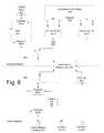
- FIG. 6is a block diagram illustrating components of an antenna assembly.
- FIG. 7is a block diagram illustrating tracking components of an antenna assembly.
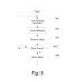
- FIG. 8illustrates an example process for providing parameters and switching between bands of operation.
- FIG. 1illustrates an example physical configuration of a low-profile, low volume, switchable band antenna assembly suitable for two-way use for portable satellite communications on-the-move (e.g., mounted on a moving vehicle).
- Such an antennacan support various data rates, such as 64 kbps transmit and 2 Mbps receive.
- the cover 101 and the components housed withinmay be mounted on a rotating platform assembly 102 .
- the rotating assembly 102may be motor driven to rotate about a vertical axis to adjust the azimuth of the assembly to track one or more signal sources, such as satellites.
- Example components of the assembly 102are discussed further below with respect to FIG. 4 .
- the rotating assembly 102may be mounted onto a block upconverter (BUC) 103 .
- the BUC 103may include frequency upconversion circuitry to convert signals from one frequency to a higher frequency for transmission. Example features of the BUC 103 are discussed further below with respect to FIG. 5 .
- FIGS. 2 a & billustrate an example of the assembly 100 with the cover 101 removed.
- the antennamay include one or more flat panel arrays 200 .
- the array 200can include a series of antenna transmission and reception elements, such as a printed circuit design with parasitic patches to extend the frequency response and provide wide band capability.
- the panel configurationallows it to maintain a flat profile with low volume, which can be advantageous for mounting on the exterior of vehicles.
- the panel array 200may be a bidirectional Ku-band array panel configured to communicate with satellites in the Ku-band (e.g., 14.0 to 14.5 GHz and 10.9 to 12.7 GHz), a Ka-band panel configured to communicate with satellites in the Ka-band (e.g., 26.5 to 40 GHz), or any other desired panel for a desired frequency band.
- the array 200is configured for a high frequency transmission such as the Ku and Ka bands discussed above. High frequency bands may be those above 2 GHz.
- the antenna assembly 100may include one or more low frequency antennas 201 .
- the low-frequency antenna 201may be, for example, an L-band panel configured to communicate with satellites in the L-band (e.g, IMMARSAT 1525 to 1646.5 MHz).
- the assembly 100 or antenna panel 200may also include antennas for communicating with terrestrial networks, such as wireless cellular telephone networks, WiMax wireless computer networks, and the like.
- the operation of the antenna 100may be controlled by a controller circuit 202 , which can include one or more microprocessors and one or more memories (e.g., flash memories, ROMs, removable media, etc.) storing computer-executable instructions that, when executed by the one or more microprocessors, cause the antenna assembly 100 and its components to perform in the various manners described herein.
- the controller circuit 202may include one or more external interfaces, such as audio/visual interfaces (displays, speakers, touch screens, etc.), computer monitor interfaces, user input device interfaces (e.g., keyboards, mice, touch screens, etc.).
- the interfacesmay also include interfaces for external control, such as an Ethernet interface, Universal Serial Bus (USB), a serial interface, or any other desired device interface.
- USBUniversal Serial Bus
- the circuit 202may also include a series of coaxial cable interfaces 203 , which can be connected to a modem device to transmit and receive signals for a customer device.
- the antennamay be connected to one or more satellite modems, which can convert the antenna's signals into a desired digital interface, such as an Internet Protocol interface.
- User devicescan connect to the IP interface, and can use the modem to send and receive data with other devices on the Internet.
- the controller circuit 202can also cause the assembly to rotate to adjust azimuth, and elevate the panel 200 to adjust elevation by tilting the panel about an elevation mount 209 , to allow the panel 200 to track one or more satellites.
- the assemblymay include one or more motors 204 (e.g., motors 204 can include azimuth and elevation motors), belts 205 , pulleys 206 , etc.
- the antenna assembly 100can also include a polarization circuit 207 , which can be configured to adjust the polarization of signals for transmission and/or reception.
- the assembly 100can also include a global positioning system (GPS) 208 , which can be configured to receive satellite timing signals and triangulate the position of the assembly 100 .
- GPSglobal positioning system
- This circuitcan further include internal 3-axis gyroscopes and corresponding orientation circuitry to detect acceleration of the assembly 100 as it moves and turns, as well as 2-axis inclinometers.
- FIGS. 3 a & billustrate isolation views of the front and rear of an example panel 200 .
- a gyroscope circuit 301In the rear view, a gyroscope circuit 301 , RF combiner 302 , and diplexer circuitry 303 can be seen.
- FIG. 4illustrates a closer view of the rotating assembly 102 .
- the rotating assembly 102may include a rotating platform 401 configured to rotate about a central axis 402 under the control of an azimuth motor 204 and its corresponding belt and pulley.
- the antenna array panel 200may be mounted to the rotating assembly.
- a dual channel rotary joint 403may be used to allow wiring and/or signals from above the rotating platform to pass through the bottom cover and reach components located under the rotating assembly 102 , such as the BUC 103 .
- FIG. 5illustrates a closer view of the BUC 103 .
- the BUC 103can be configured to upconvert signals to higher frequency bands and amplifying them for transmission, such as converting L band to Ku band. It can be shaped to fit under the radome 101 , and can have a thin profile (e.g., 2 cm).
- the BUC 103may include input and output connectors 501 , to carry signals from and to the panel 200 , DC power input 502 , cooling fins 503 and various mounting holes 504 to allow it to be mounted to the underside of the rotating assembly 102 .
- FIG. 6illustrates a block diagram representation of the example assembly shown in FIGS. 1-5 .
- the L-band patch 601may be a printed circuit antenna element of the L-band antenna 201 , and can be used for transmission and reception on the L-band (or any other desired low frequency band).
- a series of duplexers 602 a & b(which can be diplexers configured for signaling) can be used to isolate the up and down frequencies for the two-way transmission (which can be simultaneously carried out), while a low noise amplifier 603 can be used to amplify the received signal for further processing.
- This L-band portion(the top left portion of FIG.
- the source selection switch 604can be a manually or electronically controlled switch, and can selectively connect the L-band portion to the rest of the antenna and, ultimately, to user devices to allow those devices to receive L-band signals. If manual, the switch 604 can be positioned anywhere on the antenna, such as on an outer surface of the control circuit 202 .
- the other side of the source selection switch 604can be connected to reception circuitry for the panel 200 , which in some examples can be a Ku or Ka band panel.
- the panel 200may include a diplexer 605 for separating transmission and reception frequencies.
- the reception side of the diplexer 605may be connected to a receive side 207 a of polarization control circuit 207 and then to low noise block (LNB) 606 , which can process received signals to supply them to the receive selection switch 604 .
- LNBlow noise block
- the diplexer 605may also include a transmission side connected to a transmission side 207 b of the polarization control 207 .
- FIG. 7illustrates an example block configuration for using the antenna components described above.
- various pieces of user equipmente.g., computers
- the controller 202may control the operation of the antenna through the execution by a processor 202 a of instructions stored in a memory 202 b , and antenna panel 200 may receive controls for azimuth, elevation and polarization adjustments to track a satellite. Inputs from an inclinometer, gyroscope and GPS may also be used for this tracking
- the usermay, for example, view a user interface identifying various parameters that can be adjusted and/or weighted for switching between the bands supported by the antenna for the desired one- or two-way communication.
- the parametersmay identify signal conditions and priorities in which each is to be used.
- the parametercan indicate that L-band is given first priority, cellular terrestrial is next, and Ka-band is last, due to relative costs of using each band for communication.
- the parametercan also specify minimum signal strength values or signal-to-noise ratios in which each band is acceptable.
- the parameterscan indicate that the priorities can be different in different geographic locations. For example, if terrestrial cellular is extremely expensive in some regions of the world, the priority for cellular may be moved to be last, with Ka-band moving up.
- the parameterscan indicate that the priorities can be different at different times of day.
- the parametersmay indicate a security level of different bands and/or geographic locations. For example, the user may know that certain bands (or services on bands) have stronger encryption than other services or bands, and those security levels can alter the priority of the available bands.
- the parametersmay also be adjusted based on known jamming capability of enemy forces. For example, if it is known that enemy forces in a given geographic area are actively jamming in the L-band, then the priority for that area can lower the priority of the L-band.
- the look angle to a particular satellitemay also be a parameter.
- a satellite that is lower in the horizonis more likely to suffer eventual interference, even if the current signal is strong, so the user may choose to indicate that satellites having a more vertical look angle should be given higher priority.
- the look anglecan be based on the GPS position and the particular locations of the satellites that offer the different bands.
- Another parametermay be based on available bandwidth in each band. For example, different bands may be more congested than other bands, and can consequently offer different amounts of available bandwidth.
- the parametersmay indicate that a certain minimum amount of bandwidth must be available for a particular band to be used, and if the available bandwidth in that band falls below the minimum amount, then the band may be switched for a different band. The same is true for different services within the same band (e.g., two competitors that offer communication service in the L-band).
- Another parametermay be the application being used, or data type being sent. For example, if the customer device only needs to send a small amount of data, such as a text message, then a lower-bandwidth link such as some found in the L-band may be more appropriate. Similarly, if the customer device needs to send a large amount of data, such as a multimedia streaming video, then a higher-bandwidth band like Ku, Ka or X may be more appropriate. Based on the desired data to be sent, the priorities for the different bands can be altered.
- the various user parameterscan be modified and combined in any desired manner, to result in any desired user profile of prioritizing bands.
- the various parametersmay be stored in the controller's memory, and the process can proceed to step 802 .
- the antenna system(or the controller) can proceed with conducting transmission and reception for the various connected devices (e.g., consumer devices or modems 701 that request to receive or transmit information).
- the operation of the systemcan be completely autonomous, once the parameters are established.
- the antenna systemcan measure values that affect the parameters set in step 801 .
- the systemcan measure signal strengths and signal-to-noise ratios for the various bands. It can also determine the antenna's current location using the GPS component.
- the systemcan determine whether the measured values should result in a change of the band. For example, if the signal-to-noise ratio for the L-band falls below its floor threshold, the antenna controller may consult the user's parameters and determine that it should now switch from the L-band to the next priority band (e.g., Ka-band). If no switch is needed, the process can return to step 801 (which can be skipped if no new parameters are needed, e.g. if the user has not requested to change a parameter). If a switch is needed, the process may proceed to step 805 .
- the next priority bande.g., Ka-band
- the antennamay switch to the new band. This may be done, for example, by automatically changing the switch 604 and switch 607 , and requesting that the modem 701 use a different interface ( 610 / 611 / 612 ) for the communications to and from the consumer or user devices.
- step 801From there, the process can return to step 801 , and can repeat indefinitely.
- the antennacan have active control of the azimuth, elevation and polarization angles to maintain precise pointing towards the target satellite.
- the antennacan scan mechanically in both azimuth and elevation.
- the antennacan use a built-in GPS receiver to determine its position on the earth. It can then use the geographical position and the stored (e.g., in local memory) orbital location of the target satellite to determine the appropriate elevation angle. Once the elevation angle is set, the antenna can rotate in azimuth. During the scanning process the antenna can receive Eb/No information (e.g., signal to noise) from the modem to verify that the target satellite has been acquired. Once the satellite is acquired, the antenna can dither in both azimuth and elevation by ⁇ 2.0° to maintain peaking on the satellite and the transmission is enabled.
- the antennamay also include internal 3-axis gyroscopes and 2-axis inclinometers to help with the tracking while the antenna is in motion.
- the antennacan use the information from the gyros to determine when the pointing offset has reached 2.0° and can initiate transmit muting when this occurs within 100 milliseconds.
- electronic beam steeringcan be used by the controller after the satellite is acquired to maintain peaking on the satellite while the system is in motion.
- the various features and stepsmay be combined, divided, omitted, and/or augmented in any desired manner, depending on the specific secure process desired.
- the antenna systemcan include circuitry to support multiple different bands beyond the examples described. It can also support different services in the same band. For example, if two different competitors offer L-band communication services, the antenna system can switch between the two based on the parameters, and can switch to track a different satellite but in the same band.
Landscapes
- Engineering & Computer Science (AREA)
- Remote Sensing (AREA)
- Variable-Direction Aerials And Aerial Arrays (AREA)
Abstract
Description
Claims (19)
Priority Applications (2)
| Application Number | Priority Date | Filing Date | Title |
|---|---|---|---|
| US13/048,550US8761663B2 (en) | 2004-01-07 | 2011-03-15 | Antenna system |
| US14/282,209US20150311587A1 (en) | 2004-01-07 | 2014-05-20 | Antenna System |
Applications Claiming Priority (13)
| Application Number | Priority Date | Filing Date | Title |
|---|---|---|---|
| US10/498,668US6995712B2 (en) | 2001-12-19 | 2002-12-17 | Antenna element |
| US10/752,088US6999036B2 (en) | 2004-01-07 | 2004-01-07 | Mobile antenna system for satellite communications |
| US10/925,937US7379707B2 (en) | 2004-08-26 | 2004-08-26 | System for concurrent mobile two-way data communications and TV reception |
| US65012205P | 2005-02-07 | 2005-02-07 | |
| US11/071,440US20060199543A1 (en) | 2005-03-04 | 2005-03-04 | Low cost indoor test facility and method for mobile satellite antennas |
| US11/074,754US20060176843A1 (en) | 2005-02-07 | 2005-03-09 | Method and apparatus for providing low bit rate satellite television to moving vehicles |
| US11/547,576US20080193401A1 (en) | 2004-04-07 | 2005-03-23 | Hair Treatment Composition |
| US11/183,007US7385562B2 (en) | 2004-01-07 | 2005-07-18 | Mobile antenna system for satellite communications |
| US11/320,805US7705793B2 (en) | 2004-06-10 | 2005-12-30 | Applications for low profile two way satellite antenna system |
| US11/374,049US20060273965A1 (en) | 2005-02-07 | 2006-03-14 | Use of spread spectrum for providing satellite television or other data services to moving vehicles equipped with small size antenna |
| US31406610P | 2010-03-15 | 2010-03-15 | |
| US13/030,866US20110215985A1 (en) | 2004-06-10 | 2011-02-18 | Applications for Low Profile Two Way Satellite Antenna System |
| US13/048,550US8761663B2 (en) | 2004-01-07 | 2011-03-15 | Antenna system |
Related Parent Applications (1)
| Application Number | Title | Priority Date | Filing Date |
|---|---|---|---|
| US13/030,866Continuation-In-PartUS20110215985A1 (en) | 2004-01-07 | 2011-02-18 | Applications for Low Profile Two Way Satellite Antenna System |
Related Child Applications (1)
| Application Number | Title | Priority Date | Filing Date |
|---|---|---|---|
| US14/282,209ContinuationUS20150311587A1 (en) | 2004-01-07 | 2014-05-20 | Antenna System |
Publications (2)
| Publication Number | Publication Date |
|---|---|
| US20110217976A1 US20110217976A1 (en) | 2011-09-08 |
| US8761663B2true US8761663B2 (en) | 2014-06-24 |
Family
ID=44531773
Family Applications (2)
| Application Number | Title | Priority Date | Filing Date |
|---|---|---|---|
| US13/048,550Expired - Fee RelatedUS8761663B2 (en) | 2004-01-07 | 2011-03-15 | Antenna system |
| US14/282,209AbandonedUS20150311587A1 (en) | 2004-01-07 | 2014-05-20 | Antenna System |
Family Applications After (1)
| Application Number | Title | Priority Date | Filing Date |
|---|---|---|---|
| US14/282,209AbandonedUS20150311587A1 (en) | 2004-01-07 | 2014-05-20 | Antenna System |
Country Status (1)
| Country | Link |
|---|---|
| US (2) | US8761663B2 (en) |
Cited By (5)
| Publication number | Priority date | Publication date | Assignee | Title |
|---|---|---|---|---|
| US20160079665A1 (en)* | 2009-06-09 | 2016-03-17 | The Directv Group, Inc. | Rotation pointed antenna for fixed wireless wide area networks |
| US20170237155A1 (en)* | 2014-06-27 | 2017-08-17 | Viasat, Inc. | System and apparatus for driving antenna |
| WO2018225902A1 (en)* | 2017-06-09 | 2018-12-13 | 이성준 | Smart mobile base station for providing satellite signal-based multi-band wireless communication and location information, and providing method therefor |
| US10276932B2 (en) | 2017-04-13 | 2019-04-30 | Winegard Company | Antenna Positioning System |
| US20210223088A1 (en)* | 2020-01-16 | 2021-07-22 | Krohne Messtechnik Gmbh | Fill Level Sensor for Detecting a Fill Level of a Fill Medium in a Container |
Families Citing this family (12)
| Publication number | Priority date | Publication date | Assignee | Title |
|---|---|---|---|---|
| BR112014014661B1 (en)* | 2011-12-20 | 2021-12-28 | Abs Global, Ltd | METHOD FOR COMMUNICATION TO A DESTINATION THROUGH MULTIPLE SATELLITE LINKS AND TARGET DEVICE FOR RECEIVING DATA THROUGH MULTIPLE LINKS VIA SATELLITE |
| CN105190994A (en)* | 2013-03-14 | 2015-12-23 | 日本电气株式会社 | Antenna device and antenna device control method |
| US9893417B2 (en) | 2015-01-29 | 2018-02-13 | Speedcast International Limited | Satellite communications terminal for a ship and associated methods |
| US10193234B2 (en) | 2015-01-29 | 2019-01-29 | Speedcast International Limited | Method for upgrading a satellite antenna assembly and an associated upgradable satellite antenna assembly |
| US9685712B2 (en) | 2015-01-29 | 2017-06-20 | Harris Corporation | Multi-band satellite antenna assembly with dual feeds in a coaxial relationship and associated methods |
| US10014589B2 (en) | 2015-01-29 | 2018-07-03 | Speedcast International Limited | Method for upgrading a satellite antenna assembly having a subreflector and an associated satellite antenna assembly |
| US9859621B2 (en) | 2015-01-29 | 2018-01-02 | Speedcast International Ltd | Multi-band satellite antenna assembly and associated methods |
| US9628170B1 (en)* | 2016-01-26 | 2017-04-18 | Google Inc. | Devices and methods for a rotary joint with multiple wireless links |
| EP3503286B1 (en)* | 2017-12-22 | 2023-05-10 | Thales Nederland B.V. | Integrated antenna arrangement |
| US11364988B2 (en)* | 2018-06-19 | 2022-06-21 | R4 Integration Inc. | Multi-purpose shoulder panel system |
| KR102169434B1 (en)* | 2020-04-23 | 2020-10-23 | 한화시스템 주식회사 | Assembly equipment and assembly method |
| CN111987450B (en)* | 2020-07-31 | 2021-05-28 | 中国航空工业集团公司济南特种结构研究所 | Protective function antenna structure |
Citations (90)
| Publication number | Priority date | Publication date | Assignee | Title |
|---|---|---|---|---|
| US3565650A (en) | 1966-05-18 | 1971-02-23 | William A Cordon | Lightweight concrete products and a process of producing same |
| US4101335A (en) | 1976-11-04 | 1978-07-18 | Cape Boards & Panels Ltd. | Building board |
| US4771293A (en) | 1984-11-07 | 1988-09-13 | The General Electric Company P.L.C. | Dual reflector folding antenna |
| US4811026A (en) | 1987-11-16 | 1989-03-07 | Bissett William R | Mobile satellite receiving antenna especially for recreation vehicle |
| US4903033A (en) | 1988-04-01 | 1990-02-20 | Ford Aerospace Corporation | Planar dual polarization antenna |
| US5005019A (en) | 1986-11-13 | 1991-04-02 | Communications Satellite Corporation | Electromagnetically coupled printed-circuit antennas having patches or slots capacitively coupled to feedlines |
| US5038152A (en) | 1990-05-17 | 1991-08-06 | Hughes Aircraft Company | Broad band omnidirectional monocone antenna |
| US5043738A (en) | 1990-03-15 | 1991-08-27 | Hughes Aircraft Company | Plural frequency patch antenna assembly |
| US5076986A (en) | 1990-10-03 | 1991-12-31 | Ceram Sna Inc. | Process for manufacturing a composite material |
| US5207830A (en) | 1990-03-21 | 1993-05-04 | Venture Innovations, Inc. | Lightweight particulate cementitious materials and process for producing same |
| US5245348A (en) | 1991-02-28 | 1993-09-14 | Kabushiki Kaisha Toyota Chuo Kenkyusho | Tracking antenna system |
| EP0572933A1 (en) | 1992-06-02 | 1993-12-08 | Deutsche Perlite GmbH | Mortar |
| US5303393A (en) | 1990-11-06 | 1994-04-12 | Radio Satellite Corporation | Integrated radio satellite response system and method |
| US5379320A (en) | 1993-03-11 | 1995-01-03 | Southern California Edison Company | Hitless ultra small aperture terminal satellite communication network |
| US5408241A (en) | 1993-08-20 | 1995-04-18 | Ball Corporation | Apparatus and method for tuning embedded antenna |
| US5528250A (en) | 1992-11-18 | 1996-06-18 | Winegard Company | Deployable satellite antenna for use on vehicles |
| EP0810685A2 (en) | 1996-05-29 | 1997-12-03 | Toyota Jidosha Kabushiki Kaisha | Vehicle-mounted satellite signal receiving system |
| US5706015A (en) | 1995-03-20 | 1998-01-06 | Fuba Automotive Gmbh | Flat-top antenna apparatus including at least one mobile radio antenna and a GPS antenna |
| US5725652A (en) | 1994-12-19 | 1998-03-10 | Shulman; David M. | Lightweight, low water content expanded shale, clay and slate cementitious compositions and methods of their production and use |
| US5835057A (en) | 1996-01-26 | 1998-11-10 | Kvh Industries, Inc. | Mobile satellite communication system including a dual-frequency, low-profile, self-steering antenna assembly |
| WO1999031757A1 (en) | 1997-12-12 | 1999-06-24 | Allgon Ab | Dual band antenna |
| US5929819A (en) | 1996-12-17 | 1999-07-27 | Hughes Electronics Corporation | Flat antenna for satellite communication |
| US5956372A (en) | 1994-03-17 | 1999-09-21 | Digital Compression Technology, L.P. | Coding system for digital transmission compression |
| US6018320A (en) | 1997-04-30 | 2000-01-25 | Telefonaktiebolaget Lm Ericsson | Apparatus and a method relating to antenna systems |
| US6023244A (en) | 1997-02-14 | 2000-02-08 | Telefonaktiebolaget Lm Ericsson | Microstrip antenna having a metal frame for control of an antenna lobe |
| EP0985646A1 (en) | 1998-09-09 | 2000-03-15 | Tubag Trass-, Zement- und Steinwerke Gmbh | Thin bed mortar |
| US6043788A (en) | 1998-07-31 | 2000-03-28 | Seavey; John M. | Low earth orbit earth station antenna |
| US6111542A (en) | 1998-04-06 | 2000-08-29 | Motorola, Inc. | Rotating electronically steerable antenna system and method of operation thereof |
| US6124832A (en) | 1997-12-24 | 2000-09-26 | Electronics And Telecommunications Research Institute | Structure of vehicular active antenna system of mobile and satellite tracking method with the system |
| US6134423A (en) | 1995-07-13 | 2000-10-17 | Globalstar L.P. | Satellite communications system having gateway-based user RF exposure monitoring and control |
| US6157817A (en) | 1999-02-04 | 2000-12-05 | Hughes Electronics Corporation | Method for in-orbit multiple receive antenna pattern testing |
| WO2001011718A1 (en) | 1999-08-05 | 2001-02-15 | Sarnoff Corporation | Low profile steerable antenna |
| US6191734B1 (en) | 1999-03-18 | 2001-02-20 | Electronics And Telecommunications Research Institute | Satellite tracking apparatus and control method for vehicle-mounted receive antenna system |
| US6191744B1 (en) | 1999-09-27 | 2001-02-20 | Jeffrey Snow | Probe movement system for spherical near-field antenna testing |
| US6218999B1 (en) | 1997-04-30 | 2001-04-17 | Alcatel | Antenna system, in particular for pointing at non-geostationary satellites |
| US20010027146A1 (en) | 2000-01-19 | 2001-10-04 | Philip Spaziani | Electro-mechanical actuator |
| US6311128B1 (en) | 2000-02-03 | 2001-10-30 | Hughes Electronics Corporation | Combined navigation and mobile communication satellite architecture |
| US6317096B1 (en) | 1998-07-31 | 2001-11-13 | Fuba Automotive Gmbh | Antenna system |
| US20020041328A1 (en) | 2000-03-29 | 2002-04-11 | Astrovision International, Inc. | Direct broadcast imaging satellite system apparatus and method for providing real-time, continuous monitoring of earth from geostationary earth orbit and related services |
| US6377211B1 (en) | 2000-12-13 | 2002-04-23 | Lockheed Martin Corporation | Apparatus and method for pointing a directional device from a moving vehicle toward a spacecraft |
| US6407714B1 (en) | 2001-06-22 | 2002-06-18 | Ems Technologies Canada, Ltd. | Mechanism for differential dual-directional antenna array |
| US20020132578A1 (en) | 1996-12-19 | 2002-09-19 | Globalstar, Lp | Interactive fixed and mobile satellite network |
| US20020167449A1 (en) | 2000-10-20 | 2002-11-14 | Richard Frazita | Low profile phased array antenna |
| US6483472B2 (en) | 2000-01-11 | 2002-11-19 | Datron/Transo, Inc. | Multiple array antenna system |
| US6486845B2 (en) | 2000-06-23 | 2002-11-26 | Kabushiki Kaisha Toshiba | Antenna apparatus and waveguide for use therewith |
| WO2002097919A1 (en) | 2001-06-01 | 2002-12-05 | Fortel Technologies Inc | Microwave antennas |
| US6496158B1 (en) | 2001-10-01 | 2002-12-17 | The Aerospace Corporation | Intermodulation grating lobe suppression method |
| US20030060156A1 (en) | 2001-05-23 | 2003-03-27 | Giaccherini Thomas Nello | Method for securely distributing & updating information |
| US20030090416A1 (en) | 2001-11-09 | 2003-05-15 | Howell James M. | Antenna array for moving vehicles |
| US20030097658A1 (en) | 2000-08-16 | 2003-05-22 | Richards William R. | Method and apparatus for simultaneous live television and data services using single beam antennas |
| US20030181161A1 (en) | 2000-09-28 | 2003-09-25 | Guy Harles | Spread spectrum communication system using a quasi-geostationary satellite |
| US6636721B2 (en) | 1995-11-30 | 2003-10-21 | Mobile Satellite Ventures, Lp | Network engineering/systems system for mobile satellite communication system |
| US6639548B2 (en) | 2000-05-26 | 2003-10-28 | Donald E. Voss | Method for creation of planar or complex wavefronts in close proximity to a transmitter array |
| US20030214449A1 (en) | 2000-03-15 | 2003-11-20 | King Controls | Satellite locator system |
| US20030222778A1 (en) | 2002-05-29 | 2003-12-04 | Piesinger Gregory Hubert | Intrusion detection, tracking, and identification method and apparatus |
| US6678520B1 (en) | 1999-01-07 | 2004-01-13 | Hughes Electronics Corporation | Method and apparatus for providing wideband services using medium and low earth orbit satellites |
| US6695398B2 (en) | 2002-06-13 | 2004-02-24 | Webasto Sunroofs, Inc. | Spoiler sunroof mechanism |
| US6707432B2 (en) | 2000-12-21 | 2004-03-16 | Ems Technologies Canada Ltd. | Polarization control of parabolic antennas |
| US20040087294A1 (en) | 2002-11-04 | 2004-05-06 | Tia Mobile, Inc. | Phases array communication system utilizing variable frequency oscillator and delay line network for phase shift compensation |
| US20040092228A1 (en) | 2002-11-07 | 2004-05-13 | Force Charles T. | Apparatus and method for enabling use of low power satellites, such as C-band, to broadcast to mobile and non-directional receivers, and signal design therefor |
| US20040090352A1 (en) | 1999-12-03 | 2004-05-13 | Broadcom Corporation | Interspersed training for turbo coded modulation |
| WO2004075339A2 (en) | 2003-02-18 | 2004-09-02 | Starling Advanced Communications Ltd. | Low profile antenna for satellite communication |
| US6807222B1 (en) | 1998-01-22 | 2004-10-19 | British Telecommunications Public Limited Company | Receiving spread spectrum signals with narrowband interference |
| US6839039B2 (en) | 2002-07-23 | 2005-01-04 | National Institute Of Information And Communications Technology Incorporated Administrative Agency | Antenna apparatus for transmitting and receiving radio waves to and from a satellite |
| US6873256B2 (en) | 2002-06-21 | 2005-03-29 | Dorothy Lemelson | Intelligent building alarm |
| US6882321B2 (en) | 2002-04-10 | 2005-04-19 | Lockheed Martin Corporation | Rolling radar array with a track |
| US20050113040A1 (en) | 2003-11-26 | 2005-05-26 | Walker Glenn A. | Method to minimize compatibility error in hierarchical modulation using variable phase |
| US6900769B2 (en) | 2000-12-05 | 2005-05-31 | Montaplast Gmbh | Bodywork part with integrated antenna |
| US20050126430A1 (en) | 2000-10-17 | 2005-06-16 | Lightner James E.Jr. | Building materials with bioresistant properties |
| US6927736B1 (en) | 2002-05-17 | 2005-08-09 | Mission Research Corporation | System and method for integrating antennas into a vehicle rear-deck spoiler |
| US20050229235A1 (en) | 2002-06-25 | 2005-10-13 | Koninklijke Philips Electronics N.V. | Clock recovery for a dvb-t to dvb-s transmodulator |
| US6957702B2 (en) | 2003-04-16 | 2005-10-25 | Halliburton Energy Services, Inc. | Cement compositions with improved mechanical properties and methods of cementing in a subterranean formation |
| US6965343B1 (en) | 2004-06-17 | 2005-11-15 | The Aerospace Corporation | System and method for antenna tracking |
| WO2006004813A2 (en) | 2004-06-29 | 2006-01-12 | Mathew Piazza | Viscous materials and method for producing |
| US6987489B2 (en) | 2003-04-15 | 2006-01-17 | Tecom Industries, Inc. | Electronically scanning direction finding antenna system |
| US6999036B2 (en) | 2004-01-07 | 2006-02-14 | Raysat Cyprus Limited | Mobile antenna system for satellite communications |
| US20060176227A1 (en) | 2003-03-19 | 2006-08-10 | Central Glass Co., Ltd. | Antenna for vehicle |
| US20060268738A1 (en) | 2003-04-23 | 2006-11-30 | Goerke Thomas E | Radio network assignment and access system |
| US20070027624A1 (en) | 2003-04-17 | 2007-02-01 | Secretary Of State For Defence | Correction of troposhere induced errors in global positioning systems |
| US7183996B2 (en) | 2002-02-22 | 2007-02-27 | Wensink Jan B | System for remotely adjusting antennas |
| US7227508B2 (en) | 2004-01-07 | 2007-06-05 | Motia Inc. | Vehicle mounted satellite antenna embedded within moonroof or sunroof |
| US20070252765A1 (en) | 2004-09-14 | 2007-11-01 | St Electronics (Satcom & Sensor Systems) Pte. Ltd. | Portable Satellite Terminal |
| US20080018545A1 (en) | 2004-01-07 | 2008-01-24 | Ilan Kaplan | Applications for low profile two-way satellite antenna system |
| US7339520B2 (en) | 2000-02-04 | 2008-03-04 | The Directv Group, Inc. | Phased array terminal for equatorial satellite constellations |
| US20090027260A1 (en)* | 2007-07-17 | 2009-01-29 | Viasat, Inc. | Robust Satellite Detection And Maintenance Using A Multi-Beam Antenna System |
| US7492322B2 (en) | 2004-12-21 | 2009-02-17 | Electronics And Telecommunications Research Institute | Multi-satellite access antenna system |
| US7532694B2 (en) | 2003-09-09 | 2009-05-12 | Samsung Electronics Co., Ltd. | Apparatus and method for compensating for distortion caused by a phase slew of a frame reference signal in an asynchronous wideband code division multiple access communication system |
| US7760153B2 (en) | 2008-06-13 | 2010-07-20 | Lockheed Martin Corporation | Linear motor powered lift actuator |
| US20110050487A1 (en)* | 2009-05-19 | 2011-03-03 | Arsen Melconian | Systems and methods for tracking a remote source and orientation control |
| US20130135163A1 (en)* | 2008-03-05 | 2013-05-30 | Ethertronics, Inc. | Active mimo antenna configuration for maximizing throughput in mobile devices |
Family Cites Families (1)
| Publication number | Priority date | Publication date | Assignee | Title |
|---|---|---|---|---|
| CN100388275C (en)* | 2002-04-22 | 2008-05-14 | 汤姆森特许公司 | Web browser for preventing screen burn for television display |
- 2011
- 2011-03-15USUS13/048,550patent/US8761663B2/ennot_activeExpired - Fee Related
- 2014
- 2014-05-20USUS14/282,209patent/US20150311587A1/ennot_activeAbandoned
Patent Citations (96)
| Publication number | Priority date | Publication date | Assignee | Title |
|---|---|---|---|---|
| US3565650A (en) | 1966-05-18 | 1971-02-23 | William A Cordon | Lightweight concrete products and a process of producing same |
| US4101335A (en) | 1976-11-04 | 1978-07-18 | Cape Boards & Panels Ltd. | Building board |
| US4771293A (en) | 1984-11-07 | 1988-09-13 | The General Electric Company P.L.C. | Dual reflector folding antenna |
| US5005019A (en) | 1986-11-13 | 1991-04-02 | Communications Satellite Corporation | Electromagnetically coupled printed-circuit antennas having patches or slots capacitively coupled to feedlines |
| US4811026A (en) | 1987-11-16 | 1989-03-07 | Bissett William R | Mobile satellite receiving antenna especially for recreation vehicle |
| US4903033A (en) | 1988-04-01 | 1990-02-20 | Ford Aerospace Corporation | Planar dual polarization antenna |
| US5043738A (en) | 1990-03-15 | 1991-08-27 | Hughes Aircraft Company | Plural frequency patch antenna assembly |
| US5207830A (en) | 1990-03-21 | 1993-05-04 | Venture Innovations, Inc. | Lightweight particulate cementitious materials and process for producing same |
| US5038152A (en) | 1990-05-17 | 1991-08-06 | Hughes Aircraft Company | Broad band omnidirectional monocone antenna |
| US5076986A (en) | 1990-10-03 | 1991-12-31 | Ceram Sna Inc. | Process for manufacturing a composite material |
| US5303393A (en) | 1990-11-06 | 1994-04-12 | Radio Satellite Corporation | Integrated radio satellite response system and method |
| US5245348A (en) | 1991-02-28 | 1993-09-14 | Kabushiki Kaisha Toyota Chuo Kenkyusho | Tracking antenna system |
| EP0572933A1 (en) | 1992-06-02 | 1993-12-08 | Deutsche Perlite GmbH | Mortar |
| US5528250A (en) | 1992-11-18 | 1996-06-18 | Winegard Company | Deployable satellite antenna for use on vehicles |
| US5379320A (en) | 1993-03-11 | 1995-01-03 | Southern California Edison Company | Hitless ultra small aperture terminal satellite communication network |
| US5408241A (en) | 1993-08-20 | 1995-04-18 | Ball Corporation | Apparatus and method for tuning embedded antenna |
| US5956372A (en) | 1994-03-17 | 1999-09-21 | Digital Compression Technology, L.P. | Coding system for digital transmission compression |
| US5725652A (en) | 1994-12-19 | 1998-03-10 | Shulman; David M. | Lightweight, low water content expanded shale, clay and slate cementitious compositions and methods of their production and use |
| US5706015A (en) | 1995-03-20 | 1998-01-06 | Fuba Automotive Gmbh | Flat-top antenna apparatus including at least one mobile radio antenna and a GPS antenna |
| US6134423A (en) | 1995-07-13 | 2000-10-17 | Globalstar L.P. | Satellite communications system having gateway-based user RF exposure monitoring and control |
| US6636721B2 (en) | 1995-11-30 | 2003-10-21 | Mobile Satellite Ventures, Lp | Network engineering/systems system for mobile satellite communication system |
| US5835057A (en) | 1996-01-26 | 1998-11-10 | Kvh Industries, Inc. | Mobile satellite communication system including a dual-frequency, low-profile, self-steering antenna assembly |
| EP0810685A2 (en) | 1996-05-29 | 1997-12-03 | Toyota Jidosha Kabushiki Kaisha | Vehicle-mounted satellite signal receiving system |
| US5929819A (en) | 1996-12-17 | 1999-07-27 | Hughes Electronics Corporation | Flat antenna for satellite communication |
| US20020132578A1 (en) | 1996-12-19 | 2002-09-19 | Globalstar, Lp | Interactive fixed and mobile satellite network |
| US6023244A (en) | 1997-02-14 | 2000-02-08 | Telefonaktiebolaget Lm Ericsson | Microstrip antenna having a metal frame for control of an antenna lobe |
| US6018320A (en) | 1997-04-30 | 2000-01-25 | Telefonaktiebolaget Lm Ericsson | Apparatus and a method relating to antenna systems |
| US6218999B1 (en) | 1997-04-30 | 2001-04-17 | Alcatel | Antenna system, in particular for pointing at non-geostationary satellites |
| WO1999031757A1 (en) | 1997-12-12 | 1999-06-24 | Allgon Ab | Dual band antenna |
| US6124832A (en) | 1997-12-24 | 2000-09-26 | Electronics And Telecommunications Research Institute | Structure of vehicular active antenna system of mobile and satellite tracking method with the system |
| US6807222B1 (en) | 1998-01-22 | 2004-10-19 | British Telecommunications Public Limited Company | Receiving spread spectrum signals with narrowband interference |
| US6111542A (en) | 1998-04-06 | 2000-08-29 | Motorola, Inc. | Rotating electronically steerable antenna system and method of operation thereof |
| US6317096B1 (en) | 1998-07-31 | 2001-11-13 | Fuba Automotive Gmbh | Antenna system |
| US6043788A (en) | 1998-07-31 | 2000-03-28 | Seavey; John M. | Low earth orbit earth station antenna |
| EP0985646A1 (en) | 1998-09-09 | 2000-03-15 | Tubag Trass-, Zement- und Steinwerke Gmbh | Thin bed mortar |
| US6678520B1 (en) | 1999-01-07 | 2004-01-13 | Hughes Electronics Corporation | Method and apparatus for providing wideband services using medium and low earth orbit satellites |
| US6157817A (en) | 1999-02-04 | 2000-12-05 | Hughes Electronics Corporation | Method for in-orbit multiple receive antenna pattern testing |
| US6191734B1 (en) | 1999-03-18 | 2001-02-20 | Electronics And Telecommunications Research Institute | Satellite tracking apparatus and control method for vehicle-mounted receive antenna system |
| WO2001011718A1 (en) | 1999-08-05 | 2001-02-15 | Sarnoff Corporation | Low profile steerable antenna |
| US6191744B1 (en) | 1999-09-27 | 2001-02-20 | Jeffrey Snow | Probe movement system for spherical near-field antenna testing |
| US20060250285A1 (en) | 1999-12-03 | 2006-11-09 | Broadcom Corporation, A California Corporation | Interspersed training among data |
| US20040090352A1 (en) | 1999-12-03 | 2004-05-13 | Broadcom Corporation | Interspersed training for turbo coded modulation |
| US6483472B2 (en) | 2000-01-11 | 2002-11-19 | Datron/Transo, Inc. | Multiple array antenna system |
| US20010027146A1 (en) | 2000-01-19 | 2001-10-04 | Philip Spaziani | Electro-mechanical actuator |
| US6311128B1 (en) | 2000-02-03 | 2001-10-30 | Hughes Electronics Corporation | Combined navigation and mobile communication satellite architecture |
| US7339520B2 (en) | 2000-02-04 | 2008-03-04 | The Directv Group, Inc. | Phased array terminal for equatorial satellite constellations |
| US20030214449A1 (en) | 2000-03-15 | 2003-11-20 | King Controls | Satellite locator system |
| US6710749B2 (en) | 2000-03-15 | 2004-03-23 | King Controls | Satellite locator system |
| US20020041328A1 (en) | 2000-03-29 | 2002-04-11 | Astrovision International, Inc. | Direct broadcast imaging satellite system apparatus and method for providing real-time, continuous monitoring of earth from geostationary earth orbit and related services |
| US6639548B2 (en) | 2000-05-26 | 2003-10-28 | Donald E. Voss | Method for creation of planar or complex wavefronts in close proximity to a transmitter array |
| US6486845B2 (en) | 2000-06-23 | 2002-11-26 | Kabushiki Kaisha Toshiba | Antenna apparatus and waveguide for use therewith |
| US20030097658A1 (en) | 2000-08-16 | 2003-05-22 | Richards William R. | Method and apparatus for simultaneous live television and data services using single beam antennas |
| US20030181161A1 (en) | 2000-09-28 | 2003-09-25 | Guy Harles | Spread spectrum communication system using a quasi-geostationary satellite |
| US20050126430A1 (en) | 2000-10-17 | 2005-06-16 | Lightner James E.Jr. | Building materials with bioresistant properties |
| US20020167449A1 (en) | 2000-10-20 | 2002-11-14 | Richard Frazita | Low profile phased array antenna |
| US6900769B2 (en) | 2000-12-05 | 2005-05-31 | Montaplast Gmbh | Bodywork part with integrated antenna |
| US6377211B1 (en) | 2000-12-13 | 2002-04-23 | Lockheed Martin Corporation | Apparatus and method for pointing a directional device from a moving vehicle toward a spacecraft |
| US6707432B2 (en) | 2000-12-21 | 2004-03-16 | Ems Technologies Canada Ltd. | Polarization control of parabolic antennas |
| US20030060156A1 (en) | 2001-05-23 | 2003-03-27 | Giaccherini Thomas Nello | Method for securely distributing & updating information |
| WO2002097919A1 (en) | 2001-06-01 | 2002-12-05 | Fortel Technologies Inc | Microwave antennas |
| US6407714B1 (en) | 2001-06-22 | 2002-06-18 | Ems Technologies Canada, Ltd. | Mechanism for differential dual-directional antenna array |
| US6496158B1 (en) | 2001-10-01 | 2002-12-17 | The Aerospace Corporation | Intermodulation grating lobe suppression method |
| US20030090416A1 (en) | 2001-11-09 | 2003-05-15 | Howell James M. | Antenna array for moving vehicles |
| US7183996B2 (en) | 2002-02-22 | 2007-02-27 | Wensink Jan B | System for remotely adjusting antennas |
| US6882321B2 (en) | 2002-04-10 | 2005-04-19 | Lockheed Martin Corporation | Rolling radar array with a track |
| US6927736B1 (en) | 2002-05-17 | 2005-08-09 | Mission Research Corporation | System and method for integrating antennas into a vehicle rear-deck spoiler |
| US20030222778A1 (en) | 2002-05-29 | 2003-12-04 | Piesinger Gregory Hubert | Intrusion detection, tracking, and identification method and apparatus |
| US6922145B2 (en) | 2002-05-29 | 2005-07-26 | Gregory Hubert Piesinger | Intrusion detection, tracking, and identification method and apparatus |
| US6695398B2 (en) | 2002-06-13 | 2004-02-24 | Webasto Sunroofs, Inc. | Spoiler sunroof mechanism |
| US6873256B2 (en) | 2002-06-21 | 2005-03-29 | Dorothy Lemelson | Intelligent building alarm |
| US20050229235A1 (en) | 2002-06-25 | 2005-10-13 | Koninklijke Philips Electronics N.V. | Clock recovery for a dvb-t to dvb-s transmodulator |
| US6839039B2 (en) | 2002-07-23 | 2005-01-04 | National Institute Of Information And Communications Technology Incorporated Administrative Agency | Antenna apparatus for transmitting and receiving radio waves to and from a satellite |
| US20040087294A1 (en) | 2002-11-04 | 2004-05-06 | Tia Mobile, Inc. | Phases array communication system utilizing variable frequency oscillator and delay line network for phase shift compensation |
| US20040092228A1 (en) | 2002-11-07 | 2004-05-13 | Force Charles T. | Apparatus and method for enabling use of low power satellites, such as C-band, to broadcast to mobile and non-directional receivers, and signal design therefor |
| US20060197713A1 (en)* | 2003-02-18 | 2006-09-07 | Starling Advanced Communication Ltd. | Low profile antenna for satellite communication |
| US7629935B2 (en)* | 2003-02-18 | 2009-12-08 | Starling Advanced Communications Ltd. | Low profile antenna for satellite communication |
| WO2004075339A2 (en) | 2003-02-18 | 2004-09-02 | Starling Advanced Communications Ltd. | Low profile antenna for satellite communication |
| US20060244669A1 (en) | 2003-02-18 | 2006-11-02 | Starling Advanced Communications Ltd. | Low profile antenna for satellite communication |
| US20060176227A1 (en) | 2003-03-19 | 2006-08-10 | Central Glass Co., Ltd. | Antenna for vehicle |
| US6987489B2 (en) | 2003-04-15 | 2006-01-17 | Tecom Industries, Inc. | Electronically scanning direction finding antenna system |
| US6957702B2 (en) | 2003-04-16 | 2005-10-25 | Halliburton Energy Services, Inc. | Cement compositions with improved mechanical properties and methods of cementing in a subterranean formation |
| US20070027624A1 (en) | 2003-04-17 | 2007-02-01 | Secretary Of State For Defence | Correction of troposhere induced errors in global positioning systems |
| US20060268738A1 (en) | 2003-04-23 | 2006-11-30 | Goerke Thomas E | Radio network assignment and access system |
| US7532694B2 (en) | 2003-09-09 | 2009-05-12 | Samsung Electronics Co., Ltd. | Apparatus and method for compensating for distortion caused by a phase slew of a frame reference signal in an asynchronous wideband code division multiple access communication system |
| US20050113040A1 (en) | 2003-11-26 | 2005-05-26 | Walker Glenn A. | Method to minimize compatibility error in hierarchical modulation using variable phase |
| US6999036B2 (en) | 2004-01-07 | 2006-02-14 | Raysat Cyprus Limited | Mobile antenna system for satellite communications |
| US20080018545A1 (en) | 2004-01-07 | 2008-01-24 | Ilan Kaplan | Applications for low profile two-way satellite antenna system |
| US7227508B2 (en) | 2004-01-07 | 2007-06-05 | Motia Inc. | Vehicle mounted satellite antenna embedded within moonroof or sunroof |
| US6965343B1 (en) | 2004-06-17 | 2005-11-15 | The Aerospace Corporation | System and method for antenna tracking |
| WO2006004813A2 (en) | 2004-06-29 | 2006-01-12 | Mathew Piazza | Viscous materials and method for producing |
| US20070252765A1 (en) | 2004-09-14 | 2007-11-01 | St Electronics (Satcom & Sensor Systems) Pte. Ltd. | Portable Satellite Terminal |
| US7492322B2 (en) | 2004-12-21 | 2009-02-17 | Electronics And Telecommunications Research Institute | Multi-satellite access antenna system |
| US20090027260A1 (en)* | 2007-07-17 | 2009-01-29 | Viasat, Inc. | Robust Satellite Detection And Maintenance Using A Multi-Beam Antenna System |
| US20130135163A1 (en)* | 2008-03-05 | 2013-05-30 | Ethertronics, Inc. | Active mimo antenna configuration for maximizing throughput in mobile devices |
| US7760153B2 (en) | 2008-06-13 | 2010-07-20 | Lockheed Martin Corporation | Linear motor powered lift actuator |
| US20110050487A1 (en)* | 2009-05-19 | 2011-03-03 | Arsen Melconian | Systems and methods for tracking a remote source and orientation control |
Non-Patent Citations (3)
| Title |
|---|
| EP 06127356.1 extended Search Report dated Nov. 1, 2007. |
| RaySat Inc.: Press release, Online, Jan 6, 2005, retrieved from the Internet: http://www.raysat.us/news/release/01-16-05-internet.asp. |
| U.S. Appl. No. 13/030,866; NFOA mail date Sep. 19, 2011. |
Cited By (14)
| Publication number | Priority date | Publication date | Assignee | Title |
|---|---|---|---|---|
| US20160079665A1 (en)* | 2009-06-09 | 2016-03-17 | The Directv Group, Inc. | Rotation pointed antenna for fixed wireless wide area networks |
| US9653800B2 (en)* | 2009-06-09 | 2017-05-16 | The Directv Group, Inc. | Rotation pointed antenna for fixed wireless wide area networks |
| US20190157749A1 (en)* | 2014-06-27 | 2019-05-23 | Viasat, Inc. | System and apparatus for driving antenna |
| US10135127B2 (en)* | 2014-06-27 | 2018-11-20 | Viasat, Inc. | System and apparatus for driving antenna |
| US20170237155A1 (en)* | 2014-06-27 | 2017-08-17 | Viasat, Inc. | System and apparatus for driving antenna |
| US10559875B2 (en)* | 2014-06-27 | 2020-02-11 | Viasat, Inc. | System and apparatus for driving antenna |
| US20200215530A1 (en)* | 2014-06-27 | 2020-07-09 | Viasat, Inc. | System and apparatus for driving antenna |
| US10985449B2 (en)* | 2014-06-27 | 2021-04-20 | Viasat, Inc. | System and apparatus for driving antenna |
| US11165142B2 (en)* | 2014-06-27 | 2021-11-02 | Viasat, Inc. | System and apparatus for driving antenna |
| US11411305B2 (en)* | 2014-06-27 | 2022-08-09 | Viasat, Inc. | System and apparatus for driving antenna |
| US10276932B2 (en) | 2017-04-13 | 2019-04-30 | Winegard Company | Antenna Positioning System |
| WO2018225902A1 (en)* | 2017-06-09 | 2018-12-13 | 이성준 | Smart mobile base station for providing satellite signal-based multi-band wireless communication and location information, and providing method therefor |
| US20210223088A1 (en)* | 2020-01-16 | 2021-07-22 | Krohne Messtechnik Gmbh | Fill Level Sensor for Detecting a Fill Level of a Fill Medium in a Container |
| US11841260B2 (en)* | 2020-01-16 | 2023-12-12 | Krohne Messtechnik Gmbh | Fill level sensor for detecting a fill level of a fill medium in a container |
Also Published As
| Publication number | Publication date |
|---|---|
| US20110217976A1 (en) | 2011-09-08 |
| US20150311587A1 (en) | 2015-10-29 |
Similar Documents
| Publication | Publication Date | Title |
|---|---|---|
| US8761663B2 (en) | Antenna system | |
| US11588545B2 (en) | Broadband satellite terminal | |
| KR101936252B1 (en) | Antenna system loaded in vehicle | |
| US8571464B2 (en) | Omnidirectional switchable broadband wireless antenna system | |
| US11355857B2 (en) | Directable antenna system and method for improved communications quality | |
| US20090083804A1 (en) | System and Method for Low Cost Mobile TV | |
| US7813314B2 (en) | Mobile router device | |
| US10734710B1 (en) | Electronic devices with antenna arrays | |
| US20100218224A1 (en) | System and Method for Low Cost Mobile TV | |
| CN110710136B (en) | Satellite terminal system with wireless link | |
| CN110838868B (en) | Kaku double-frequency-band portable satellite earth station capable of being switched rapidly | |
| EP1949709B1 (en) | Apparatus and method for controlling a signal | |
| WO2014043401A1 (en) | Wireless antenna communicating system and method | |
| CN1742500B (en) | Mobile Communication System Using Directional Antenna | |
| US11115792B2 (en) | Vehicular high-speed network system | |
| JP2000232312A (en) | Satellite antenna system and mobile phone | |
| US7277058B2 (en) | Wireless communication device antenna for improved communication with a satellite | |
| CN117728874A (en) | Device driven communication switching | |
| KR20010001091A (en) | Mast antenna system | |
| JP7635005B2 (en) | Satellite communication device, its transmitter and transmission method | |
| KR20080024838A (en) | A mobile terminal for selecting an antenna by moving the display device | |
| CA2779740A1 (en) | Cellular booster for a well site |
Legal Events
| Date | Code | Title | Description |
|---|---|---|---|
| AS | Assignment | Owner name:RAYSAT ANTENNA SYSTEMS, L.L.C., VIRGINIA Free format text:ASSIGNMENT OF ASSIGNORS INTEREST;ASSIGNORS:KAPLAN, ILAN;DIFONZO, DANIEL;BRUESTLE, KEVIN;AND OTHERS;SIGNING DATES FROM 20110314 TO 20110315;REEL/FRAME:026050/0644 | |
| AS | Assignment | Owner name:SILICON VALLEY BANK, CALIFORNIA Free format text:CORRECTION TO CORRECT THE INCORRECT NUMBERS 016481, 215985, 0802199, 0233600, 0334404, 0246676, 4237583, 7253018, 8205201 FILED WITH THE DOCUMENT RECORDED AT REEL 028681 FRAME 0929 AND TO ADD NUMBERS INADVERTENTLY LEFT OFF OF THE SAME FILING; 13/048,550 AND 13/296,880;ASSIGNORS:SPACENET INC.;RAYSAT ANTENNA SYSTEMS, L.L.C. A DELAWARE LIMITED LIABILITY COMPANY;STARBAND COMMUNICATIONS INC., A DELAWARE CORPORATION;AND OTHERS;REEL/FRAME:028832/0573 Effective date:20120509 | |
| AS | Assignment | Owner name:GILAT NORTH AMERICA, L.L.C., VIRGINIA Free format text:CHANGE OF NAME;ASSIGNOR:RAYSAT ANTENNA SYSTEMS, L.L.C.;REEL/FRAME:031205/0876 Effective date:20130515 | |
| AS | Assignment | Owner name:RAYSAT ANTENNA SYSTEMS L.L.C., A DELAWARE LIMITED Free format text:RELEASE;ASSIGNOR:SILICON VALLEY BANK;REEL/FRAME:031336/0896 Effective date:20130919 Owner name:SPACENET INC., VIRGINIA Free format text:RELEASE;ASSIGNOR:SILICON VALLEY BANK;REEL/FRAME:031336/0896 Effective date:20130919 Owner name:WAVESTREAM CORPORATION, A DELAWARE CORPORATION, VI Free format text:RELEASE;ASSIGNOR:SILICON VALLEY BANK;REEL/FRAME:031336/0896 Effective date:20130919 Owner name:SPACENET INTEGRATED GOVERNMENT SOLUTIONS, INC., A Free format text:RELEASE;ASSIGNOR:SILICON VALLEY BANK;REEL/FRAME:031336/0896 Effective date:20130919 Owner name:STARBAND COMMUNICATIONS, INC., A DELAWARE CORPORAT Free format text:RELEASE;ASSIGNOR:SILICON VALLEY BANK;REEL/FRAME:031336/0896 Effective date:20130919 | |
| AS | Assignment | Owner name:GILAT SATELLITE NETWORKS LTD., ISRAEL Free format text:ASSIGNMENT OF ASSIGNORS INTEREST;ASSIGNOR:SPACENET INC.;REEL/FRAME:031760/0822 Effective date:20131202 Owner name:SPACENET INC., VIRGINIA Free format text:ASSIGNMENT OF ASSIGNORS INTEREST;ASSIGNOR:GILAT NORTH AMERICA, L.L.C.;REEL/FRAME:031760/0301 Effective date:20131126 | |
| STCF | Information on status: patent grant | Free format text:PATENTED CASE | |
| MAFP | Maintenance fee payment | Free format text:PAYMENT OF MAINTENANCE FEE, 4TH YEAR, LARGE ENTITY (ORIGINAL EVENT CODE: M1551) Year of fee payment:4 | |
| FEPP | Fee payment procedure | Free format text:MAINTENANCE FEE REMINDER MAILED (ORIGINAL EVENT CODE: REM.); ENTITY STATUS OF PATENT OWNER: LARGE ENTITY | |
| LAPS | Lapse for failure to pay maintenance fees | Free format text:PATENT EXPIRED FOR FAILURE TO PAY MAINTENANCE FEES (ORIGINAL EVENT CODE: EXP.); ENTITY STATUS OF PATENT OWNER: LARGE ENTITY | |
| STCH | Information on status: patent discontinuation | Free format text:PATENT EXPIRED DUE TO NONPAYMENT OF MAINTENANCE FEES UNDER 37 CFR 1.362 | |
| FP | Lapsed due to failure to pay maintenance fee | Effective date:20220624 |