US8761387B2 - Analog transmit crosstalk canceller - Google Patents
Analog transmit crosstalk cancellerDownload PDFInfo
- Publication number
- US8761387B2 US8761387B2US11/800,433US80043307AUS8761387B2US 8761387 B2US8761387 B2US 8761387B2US 80043307 AUS80043307 AUS 80043307AUS 8761387 B2US8761387 B2US 8761387B2
- Authority
- US
- United States
- Prior art keywords
- connector
- signal
- crosstalk
- cancellation
- communication
- Prior art date
- Legal status (The legal status is an assumption and is not a legal conclusion. Google has not performed a legal analysis and makes no representation as to the accuracy of the status listed.)
- Active, expires
Links
- 238000004891communicationMethods0.000claimsabstractdescription82
- 239000004020conductorSubstances0.000claimsabstractdescription44
- 238000000034methodMethods0.000claimsdescription23
- 230000003111delayed effectEffects0.000claimsdescription13
- 230000008569processEffects0.000claimsdescription5
- 238000001914filtrationMethods0.000claimsdescription3
- 230000008878couplingEffects0.000description22
- 238000010168coupling processMethods0.000description22
- 238000005859coupling reactionMethods0.000description22
- 230000006978adaptationEffects0.000description20
- 238000010586diagramMethods0.000description9
- 238000012545processingMethods0.000description8
- 230000008901benefitEffects0.000description7
- 230000001934delayEffects0.000description5
- 238000004458analytical methodMethods0.000description4
- 230000005540biological transmissionEffects0.000description4
- 230000008859changeEffects0.000description3
- 230000003595spectral effectEffects0.000description3
- 238000012360testing methodMethods0.000description3
- 239000000872bufferSubstances0.000description2
- 238000013461designMethods0.000description2
- 230000003321amplificationEffects0.000description1
- 238000013459approachMethods0.000description1
- 230000015556catabolic processEffects0.000description1
- 238000006243chemical reactionMethods0.000description1
- 238000012937correctionMethods0.000description1
- 238000006731degradation reactionMethods0.000description1
- 230000005672electromagnetic fieldEffects0.000description1
- 238000005516engineering processMethods0.000description1
- 230000020169heat generationEffects0.000description1
- 238000009434installationMethods0.000description1
- 238000003199nucleic acid amplification methodMethods0.000description1
- 230000009467reductionEffects0.000description1
- 230000004044responseEffects0.000description1
- 238000012549trainingMethods0.000description1
Images


Classifications
- H—ELECTRICITY
- H04—ELECTRIC COMMUNICATION TECHNIQUE
- H04B—TRANSMISSION
- H04B3/00—Line transmission systems
- H04B3/02—Details
- H04B3/32—Reducing cross-talk, e.g. by compensating
Definitions
- the inventionrelates to communication systems and in particular to a method and apparatus for canceling crosstalk using transmit side processing.
- Communication systemsoften transmit communication signals between stations or remote locations.
- the different locationsmay be remote locations or as close as a foot apart in a backplane environment.
- the communications signalsare often transmitted over metallic conductors, hereinafter lines, which are often located in close proximity. The proximity of the lines are particularly close when a high density connector is utilized to connect multiple lines to the communication system.
- Crosstalk coupling between linesoccurs when an electromagnetic field generated by a signal in one line couples into and becomes part of a signal in another line.
- Crosstalkis generally understood to be unwanted and undesirable.
- the primary source of contactis the mechanical assembly consisting of the PCB/connector/cable launch or vice versa (cable to PCB) and can be considered as the end point.
- crosstalkcouples between lines based on the parameters of the signal on the line and the proximity of the lines. Either or both sources can dominate depending on the system. As a result, signals in proximately located lines will contain unwanted crosstalk coupling from other nearby lines.
- the invention disclosed hereinovercomes the drawbacks of the prior art by providing a method and apparatus for crosstalk cancellation.
- an analog transmit side crosstalk cancellation systemwhich may be located at or near the connector of a communication channel, cable, or backplane.
- a transmit side crosstalk cancellation systemis contained within a connector and comprises a delay configured to receive and delay a first communication signal from a first line of the communication system to create a delayed signal.
- An analog filterthen receives and filters the delayed signal to create a filtered signal while an amplifier receives and amplifies the filtered signal to create a cancellation signal.
- a junctionis also provided to combine the cancellation signal with a second communication signal on a second line of the communication system such that the first line and the second line are adjacent in a connector.
- the crosstalk cancellation systemis part of a connector of a communication cable. It is also contemplated that the connector may be part of a circuit board connector or part of a backplane.
- the systemmay also comprise a third line which is not adjacent to the first line such that a signal on the third line is not utilized to create a cancellation signal to be combined with the signal on the second line.
- the crosstalk cancellation systemis contained within a separate element and configured for use between the communication system and the connector. The second communication signal receives cancellation signals from each adjacent conductor in the connector.
- the connectorconfigured with a crosstalk cancellation system.
- the connectorcomprises an outer housing such that, the housing has an outer insulative cover, and a first opening and second opening. Also part of this system is two or more input nodes at the first opening which are configured to each receive a signal, and at least one crosstalk cancellation system associated with each node.
- the cross talk cancellation systemis configured to process the signal at the node to generate a crosstalk cancellation signal.
- the systemfurther comprises at least one junction associated with each crosstalk cancellation system configured to combine each received signal with at least one crosstalk cancellation signal to create two or more crosstalk canceled signals.
- Two or more output nodes at the second opening in the housingare each configured to present one of the two or more crosstalk canceled signals out of the connector.
- the crosstalk cancellation systemcomprises a delay and a filter. It is contemplated that the crosstalk cancellation system may further comprise an amplifier which may increase or decrease the magnitude of the crosstalk cancellation signal.
- the connectoris attached to or is part of a communication cable or a backplane.
- At least one of the junctionsis configured to combine a cancellation signal from the crosstalk cancellation system that is associated with each adjacent node.
- the term adjacentcomprises only vertically adjacent and horizontally adjacent.
- the term adjacentmay further comprise diagonally adjacent.
- Also disclosed hereinis a method for canceling crosstalk within or at a connector.
- the steps of such a methodcomprise receiving, from a communication system, a first signal, a second signal, and a third signal.
- the signalsare carried on a first conductor, a second conductor, and a third conductor respectively and the first conductor is adjacent the third conductor and the second conductor is adjacent the third conductor.
- the methoddelays the first signal to create a delayed first signal and delays the second signal to create a delayed second signal.
- the methodfilters the first delayed signal with an analog filter to created a first filtered signal and filters the second delayed signal with an analog filter to created a second filtered signal.
- Amplifying of the first filtered signalcreates a first cancellation signal and amplifying the second filtered signal to create a second cancellation signal. Thereafter, combining occurs wherein the first cancellation signal and the second cancellation signal are combined with the third signal to cancel crosstalk from the first signal and crosstalk from the second signal into the third signal. This creates a processed third signal which is output to a connector or to a communication cable.
- This methodmay occur in a communication cable connector.
- the step of outputting the processed third signal to a connector or to a communication cablecomprises outputting the processed third signal to a backplane.
- the methodmay occur between all adjacent conductors of a connector.
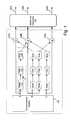
- FIG. 1illustrates an example block diagram of a communication system with a transmit side crosstalk pre-cancellation system as part of the communication system.
- FIG. 2illustrates an example block diagram of a communication system with a transmit side crosstalk pre-cancellation system as a separate element.
- FIG. 3illustrates an example block diagram of a communication system with a transmit side crosstalk pre-cancellation system as part of the multi-line connector.
- FIGS. 4A and 4Billustrate a connector line location diagram showing possible crosstalk cancellation patterns.
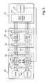
- FIG. 5illustrates an example block diagram of an adaptable crosstalk cancellation system.
- FIG. 1illustrates an example embodiment of a communication transmit system with crosstalk cancellation.
- the crosstalk cancellation systemis configured at part of the transmitter portion of the communication system. In this sense, it pre-cancels crosstalk prior to the signal traveling through the channel.
- receiver side cancellationprovides numerous benefits over prior art receiver side cancellation.
- the signal power levelsare at their highest, and coupling can occur within or near the connector.
- crosstalk which couples at or near the transmitteris subject to medium frequency response of the channel. This distortion makes receiver side crosstalk cancellation more difficult.
- Receiver side cancellationalso requires large delays which are based on or related to the transmission line length. Such delays are difficult to implement and consume additional space. This cancellation system may thus pre-distort the transmitted signal with cancellation signal to thereby cancel coupling which will occur during transmission.
- dynamic adaptationmay not be necessary if the crosstalk coupling does not change over time.
- a communication system 100may comprise any type communication system configured to provide a communication signal for transmission over the channel.
- the communication systemcomprises a cables consisting of twin-axial cable with high-density connectors or PCB backplane connectors.
- the output of the communication system 100is provided directly to a summing or subtracting junction 104 A, 104 B and 104 C as shown.
- the output of the communication system 100is also provided to a crosstalk cancellation system 108 as shown within the dashed line.
- the crosstalk cancellation system 108comprises a delay element 112 , a filter 116 , and an amplifier 120 as shown.
- the elements 112 , 116 , and 120are configured in serial manner.
- the delay 112is configured to delay the output communication signal by an amount that matches the delay resulting from the signal delay between the output of the crosstalk canceller to the main source of crosstalk. This may be, in typical embodiments crosstalk occurring in or on the path of the equalizer IC, package, the PCB to the male and female high-density connectors and/or the interface [splice point] between the connector of the cable.
- the delaymay conceptually be positive or negative or measured from any reference point or reference time.
- a delay elementmay also be placed in the path of the primary signal, such as between element 100 and 104 so that the outgoing signal may be delayed to account for any delays in the cancellation system 108 .
- the delay(s) 112can be part of the CDR based on a DLL approach.
- the filter 116is configured to modify the communication signal in such a manner that the output of the filter comprises the signal having spectral content generally similar or related to the crosstalk that couples to the nearby line.
- the processing by filter 116is performed to generate a crosstalk cancellation signal having spectral content that will cancel crosstalk that couples from channel A into channel B.
- the filtermay comprise a high pass filter.
- the filter 116may comprise an inverse filter such as a programmable analog filter with 20 to 30 dB of gain.
- the output of the filter 116feeds into the amplifier 120 which is configured to amplify or attenuate the signal output from the filter to a magnitude that matches the crosstalk coupling from the channel A to channel B.
- the amplifier 120may comprise any type amplifier configured to amplifier a signal.
- the amplifiermay be inverting or non-inverting as may be warranted to cancel the crosstalk. For example, if a summing junction is utilized, then an inverting amplifier may be appropriate to create an inverted cancellation signal that subtracts, from the signal, the coupling that will occur.
- the gainmay be set to compensate for connector losses.
- the output of the amplifieris the crosstalk cancellation signal and is provided to the summing junction 104 B.
- the junction 104 Bcombines the cancellation signal, such as from an inverting amplifier, from the outgoing communication signal on channel B. If the junction 104 performs subtraction, then the junction may comprise a combination node and the cancellation signal may not be inverted by the amplifier 120 . It is contemplated that the correction or cancellation signals may be AC coupled to an output buffer. This eliminates the need for custom designed linear output buffers.
- the output of the summing junctionmay connect to a driver (not shown) and eventually to connectors, such as multi-line connector 130 .
- the connectoris electrically linked to a line 140 .
- the other lines, B and Cfunction in a similar manner.
- the pre/de-emphasis signalmay or may not be added to the crosstalk signal. This may depend on the amplitude and freq. content of the pre/de-emphasis. For example, pre/de-emphasis may occur prior to or within element 100 , in which case the pre/de-emphasis would feed into the crosstalk cancellation system 108 .
- pre/de-emphasismay occur after element 104 but may be small, in relation to the overall outgoing signal, and hence create only a small amount of crosstalk and not warrant cancellation.
- the pre/de-emphasismay or may not need to be corrected for by crosstalk cancellation.
- FIG. 1shows the cancellation signal as being generated to cancel crosstalk from only adjacent lines.
- line Ais adjacent to only line B and hence only generates a cancellation signal to cancel coupling from line A to line B.
- line Bis adjacent to line A and line C and hence generates a cancellation signal for lines A and C.
- any arrangement of cancellationmay occur between the various lines. It is contemplated that many lines may be in the system and as such, there is no limit on the number of line that can be in the connector or communication system. Moreover, any number of the lines, which are in the connector or communication system, may be involved in the crosstalk cancellation operation.
- the cancellation system 108must be tailored to process the signal in a manner that will result in a crosstalk cancellation signal, i.e. a signal the cancels the crosstalk that couples from nearby channels.
- a crosstalk cancellation signali.e. a signal the cancels the crosstalk that couples from nearby channels.
- the amount of delay, and spectral effect of the filtering, and the level of amplificationmust be adjusted to match the amount of crosstalk that couples.
- the delay 112 , filter 116 , and amplifier 120may be adjusted based on testing that occurs when the system is installed, or based on testing that occurs in the lab or during design. Adaptation may also occur, either during training or during operation.
- the close proximity of the lines in the connector 130is the primary source of the crosstalk coupling and as such, the crosstalk that couples from the connector is measured.
- the processing by the delay 112 , filter 116 , and amplifier 120is selected to counter the crosstalk coupling that results from the close proximity of the lines in the connector.
- the cancellation system 108is considered to account for connector crosstalk. In a connector, such as generally shown in FIGS. 4A and 4B which is discussed below, this may significantly reduce signal degradation.
- the cancellation system 108may be configured with analog elements.
- the power savingsas compared to a digital implementations, is a benefit. Reductions in power consumption also reduce heat generation.
- a digital implementation of the filter 116may require a multiple stage FIR filter while an analog implementation may only use a low power 1 st or 2 nd order passive or low power filter.
- the crosstalk that is pre-canceled at the transmitter prior to transmission of the signaldoes not travel through the channel.
- the crosstalk couplingis not also affected by the channel, which may cause the crosstalk and the signal itself to become more difficult to remove or recover at the receiver.
- the cancellation systemcan clearly ‘know’ the coupling signal because the signal that generates the coupling signal is adjacent or near the victim signal and hence, the cancellation signal may be created.
- analog filtersmay be simpler to construct and tune as compared to a digital filter. This results in cost, size, and efficiency savings. In addition, this configuration provides low power dissipation. In addition, once the cancellation system is established to compensate for the connector, the input length and characteristics will not affect the setting and there is no lock and configuration time.
- FIG. 2illustrates an example block diagram of a communication system with a transmit side crosstalk pre-cancellation system as a separate element.
- the crosstalk cancellation systemis contained within a separate element 200 and located between the communication system 100 and the connector 130 .
- the cancellation system 200may be configured separate from the communication system and connector and configured based on the communication system, communication signals, and the connector. Hence, it may be tailored to fit the particular environment of use to be adjustable for various parameters.
- FIG. 3illustrates an example block diagram of a communication system with a transmit side crosstalk pre-cancellation system configured as part of the multi-line connector.
- the crosstalk cancellation systemis contained within and is part of the connector 300 .
- the amount and type of crosstalk cancellationmay be tailored to the particular connector in use and automated to automatically work with the connector. This simplifies operation and installation by having, in the field, the same elements, but with the connector containing an integrated cancellation system.
- the connectorsmay be cascaded to provide additional cancellation or cancellation for multiple cable paths in the case of stacked connectors.
- FIGS. 4A and 4Billustrate a line location diagram within a multi-conductor connector showing possible crosstalk cancellation patterns. These figures are provided to aid in understanding and hence, connector configuration and/or cancellation patterns should not be limited to this particular arrangement.
- FIG. 4Aan outer housing 404 of a connector 400 is shown with multiple conductors A 1 through H 6 as shown. As can be appreciated, certain conductors are closer to some conductors than other conductors. With reference to conductor B 4 , the closest conductors are conductors A 3 -A 5 , B 3 and B 5 , and C 3 -C 5 . These conductors are shown within the dashed line around conductor B 4 .
- the crosstalk cancellation systemis configured to cancel cross talk coupling that occurs across these lines, namely, from the signal on conductors A 3 -A 5 , B 3 and B 5 , and C 3 -C 5 into conductor B 4 .
- the patterns of crosstalk cancellation amongst adjacent conductors in the connector 400can be repeated throughout the pattern of the connector.
- crosstalk cancellation patternis shown around conductor F 3 .
- the crosstalk cancellation systemmay be configured to only cancel crosstalk coupling from conductors with the dashed line, namely, conductors E 3 , F 2 , F 4 , and G 3 . Of course, it is contemplated that this pattern be repeated throughout the conductor 400 .
- FIG. 4Balso illustrates a connector 400 with an outer housing 404 configured with multiple conductors. Depending on the level of crosstalk cancellation the pattern shown by the dashed line may be included and repeated for crosstalk cancellation around conductor 4 D and other conductors. Any pattern of crosstalk cancellation may be established between conductors in the connector 400 .
- FIG. 4Balso shows a possible cancellation pattern around conductor (or pin) G 2 .
- a vertical shieldexists between columns (not a significant source of jitter) so the crosstalk cancellation coupling occurs between the conductor G 2 and the adjacent top (F 2 ) and adjacent bottom (H 2 ).
- the cancellation systemcould cancel, on a repeating basis, crosstalk coupling from adjacent conductors that are above and below.
- FIG. 5illustrates a block diagram of an adaptable crosstalk cancellation system.
- communication cables 500connect the various communication elements.
- the top set of cables 500carry signals traveling in a first direction, while the bottom set of cables 500 carry signal traveling in a second and opposite direction.
- a first processing block 504communicates with a second processing block 508 as shown.
- a removable adaptation block 512which may be configured as a bus or backplane connected card.
- the adaptation block 512may comprise a test card.
- the first block 504comprises a serializer/deserializer (SerDes) 516 configured to perform data conversion processing on the data.
- the serializer/deserializeris generally understood in the art and hence not described in detail.
- the SerDes 516communicates over a backplane 520 with a quad equalizer with CDR and AXC module 524 as shown.
- the equalizer componentmay comprise a low noise equalizer, filter, or any other similar or related device.
- the analog crosstalk canceller (AXC)is part of element 524 .
- the AXCmay be part of the connector 528 .
- the AXCmay be located at any location in the system or connector shown in FIG. 5 to achieve the cancellation as described herein.
- element 524communicates through a high density connector 528 to the second module 508 .
- the second module 508receives and exchanges data with the first module 504 through an opposing high density connector 532 which in turn feeds into a quad equalizer with CDR module 536 .
- the output of element 536connects to the backplane 540 , which in turn provides the signals on cables 500 to the adaptation block 512 .
- the adaptation block 512comprises a signal quality analysis circuit 544 and a processor 548 connected as shown.
- the processor 548connects to the first processing block 504 as shown or in any other manner via any path to provide adaptation signals.
- the signal quality analysis circuit 544comprises a circuit that is capable of measuring one or more aspects of signal quality of signal error.
- circuit 544comprises a 16 ⁇ 16 ⁇ Point signal conditioner available from Mindspeed Technologies Inc, of Newport Beach, Calif.
- Signal quality or errormay comprise the eye opening, alignment, signal contour, slicer error, or any other factor.
- This informationis provided to the processor 548 , which is configured with software to processes the signal quality or error information to generate one or more configuration settings (adaptation signal) for the analog crosstalk canceller as found in element 524 . Any type processor, controller, or processing logic may be utilized.
- the analog crosstalk cancelleras contained in element 524 or a connector. It is configured to cancel crosstalk and operate as defined herein.
- an adaptation operationmay occur at startup, during configuration, periodically during operation, or at any other time.
- the adaptation operationmay occur when the signals on the bus 500 are received at the signal quality analysis circuit 544 .
- the signal quality analysis circuit 544processes the signal to determine one or more aspects of the signal, such as comparison to known transmitted signals, or based on a slicer or quantizer output, or in any other manner, to obtain an indication of aspects of the received signals or received signal quality.
- the received signalis compared to a known transmitted version of that signal to isolate or identify crosstalk coupling from one or more of the nearby cables or connector pins into a victim channel. This information is then passed onto the processor 548 , which in this embodiment is configured to generate one or more adaptation signals which are forwarded to the analog crosstalk cancellers of element 524 .
- adaptation signalsmay comprise canceller settings or other data which is used by the analog crosstalk canceller to establish the operating parameters for the analog crosstalk canceller.
- the adaptation signalmay comprise data that controls or sets one or more of the following: delay values or amounts, filter coefficients or filter parameters, amplifier or attenuation levels, switch selection, summation junction behavior, or any other analog crosstalk canceller parameter or setting.
- the adaptation signalscustom tailor the analog crosstalk canceller settings to optimally cancel the actual crosstalk coupling between signals traveling on through connectors and cables 500 thereby improving the accuracy of the analog crosstalk canceller.
- the adaptation signalsmay be generated by the processor 548 and manually entered by a technician in to the analog crosstalk canceller.
- the adaptation blockmay comprise a bus connected card or module that is maintained in the communication device, or selectively inserted for adaptation.
- the adaptationmay occur constantly, or intermittently.
- crosstalk in an established systemwill not change over time, or if changes do occur, the changes in crosstalk coupling will be small. This is unlike a CO to CPE communication link subject to numerous dynamic crosstalk offenders during thousands of feet communication link. Therefore, in one embodiment, adaptation may occur initially at set up, and the module 512 removed from the system.
- the custom tailored analog crosstalk canceller settings established during adaptationmay not need to be adapted during operation because in certain systems the crosstalk coupling will not change over time.
Landscapes
- Engineering & Computer Science (AREA)
- Computer Networks & Wireless Communication (AREA)
- Signal Processing (AREA)
- Cable Transmission Systems, Equalization Of Radio And Reduction Of Echo (AREA)
- Details Of Connecting Devices For Male And Female Coupling (AREA)
Abstract
Description
Claims (20)
Priority Applications (1)
| Application Number | Priority Date | Filing Date | Title |
|---|---|---|---|
| US11/800,433US8761387B2 (en) | 2006-05-04 | 2007-05-03 | Analog transmit crosstalk canceller |
Applications Claiming Priority (2)
| Application Number | Priority Date | Filing Date | Title |
|---|---|---|---|
| US79759806P | 2006-05-04 | 2006-05-04 | |
| US11/800,433US8761387B2 (en) | 2006-05-04 | 2007-05-03 | Analog transmit crosstalk canceller |
Publications (2)
| Publication Number | Publication Date |
|---|---|
| US20080013742A1 US20080013742A1 (en) | 2008-01-17 |
| US8761387B2true US8761387B2 (en) | 2014-06-24 |
Family
ID=38949273
Family Applications (1)
| Application Number | Title | Priority Date | Filing Date |
|---|---|---|---|
| US11/800,433Active2031-08-15US8761387B2 (en) | 2006-05-04 | 2007-05-03 | Analog transmit crosstalk canceller |
Country Status (1)
| Country | Link |
|---|---|
| US (1) | US8761387B2 (en) |
Cited By (1)
| Publication number | Priority date | Publication date | Assignee | Title |
|---|---|---|---|---|
| US20170264471A1 (en)* | 2016-03-09 | 2017-09-14 | Qualcomm Incorporated | Intelligent equalization for a three-transmitter multi-phase system |
Families Citing this family (4)
| Publication number | Priority date | Publication date | Assignee | Title |
|---|---|---|---|---|
| GB2428149B (en)* | 2005-07-07 | 2009-10-28 | Agilent Technologies Inc | Multimode optical fibre communication system |
| US7948862B2 (en)* | 2007-09-26 | 2011-05-24 | Solarflare Communications, Inc. | Crosstalk cancellation using sliding filters |
| US9977096B2 (en) | 2011-07-07 | 2018-05-22 | Biosense Webster (Israel) Ltd. | Connector with active shielding |
| JP2016225893A (en)* | 2015-06-02 | 2016-12-28 | 日本電信電話株式会社 | Parallel amplifier |
Citations (70)
| Publication number | Priority date | Publication date | Assignee | Title |
|---|---|---|---|---|
| US4359778A (en) | 1981-02-05 | 1982-11-16 | Zenith Radio Corporation | Channel equalizer and method for cancelling ghosts |
| US4583235A (en) | 1982-11-11 | 1986-04-15 | Siemens Aktiengesellschaft | Self-adjusting equalizer configuration which automatically adjusts to the cable length |
| EP0250048A1 (en) | 1986-06-20 | 1987-12-23 | Koninklijke Philips Electronics N.V. | Frequency-domain block-adaptive digital filter |
| US4878232A (en) | 1985-11-20 | 1989-10-31 | Stc Plc | Data transmission system |
| US4956838A (en) | 1988-03-15 | 1990-09-11 | Etat Francais Represente Par Le Ministre Des Postes, Telecommunications Et De L'espace (Centre National D'etudes Des Telecommunications) | Echo cancelling device with frequency sub-band filtering |
| US5222084A (en) | 1990-06-25 | 1993-06-22 | Nec Corporation | Echo canceler having adaptive digital filter unit associated with delta-sigma modulation circuit |
| US5249200A (en) | 1991-07-30 | 1993-09-28 | Codex Corporation | Device and method for combining precoding with symbol-rate spectral shaping |
| US5293405A (en) | 1991-10-31 | 1994-03-08 | International Business Machines Corp. | Adaptive equalization and regeneration system |
| US5293402A (en) | 1991-05-02 | 1994-03-08 | Bell Communications Research, Inc. | Wideband digital equalizers for subscriber loops |
| US5305307A (en) | 1991-01-04 | 1994-04-19 | Picturetel Corporation | Adaptive acoustic echo canceller having means for reducing or eliminating echo in a plurality of signal bandwidths |
| US5388124A (en) | 1992-06-12 | 1995-02-07 | University Of Maryland | Precoding scheme for transmitting data using optimally-shaped constellations over intersymbol-interference channels |
| US5471501A (en) | 1991-06-27 | 1995-11-28 | Hughes Aircraft Company | Enhanced digital communications receiver using channel impulse estimates |
| US5633863A (en) | 1994-07-07 | 1997-05-27 | Siemens Schweiz Ag | Echo canceler |
| US5646958A (en) | 1994-12-26 | 1997-07-08 | Nec Corporation | Decision feedback equalizer for canceling short-and long-multipath components using correspondingly delayed decision symbols |
| US5856970A (en) | 1996-08-05 | 1999-01-05 | Motorola, Inc. | Multi-channel echo cancellation method and apparatus |
| US5896452A (en) | 1996-05-24 | 1999-04-20 | Motorola, Inc. | Multi-channel echo canceler and method using convolution of two training signals |
| US5909466A (en) | 1995-09-15 | 1999-06-01 | France Telecom | Adaptive equalizer for digital communications systems |
| US6052420A (en)* | 1997-05-15 | 2000-04-18 | Northern Telecom Limited | Adaptive multiple sub-band common-mode RFI suppression |
| US6088827A (en) | 1997-08-28 | 2000-07-11 | Level One Communications, Inc. | 1000BASE-T packetized trellis coder |
| US6147979A (en) | 1997-08-12 | 2000-11-14 | Lucent Technologies, Inc. | System and method for echo cancellation in a communication system |
| US6160790A (en) | 1996-12-31 | 2000-12-12 | Paradyne Corporation | Crosstalk canceller system and method |
| US6167082A (en) | 1997-03-06 | 2000-12-26 | Level One Communications, Inc. | Adaptive equalizers and methods for carrying out equalization with a precoded transmitter |
| US6201831B1 (en) | 1998-11-13 | 2001-03-13 | Broadcom Corporation | Demodulator for a multi-pair gigabit transceiver |
| US6212225B1 (en) | 1998-05-14 | 2001-04-03 | Bradcom Corporation | Startup protocol for high throughput communications systems |
| US6226332B1 (en) | 1998-11-13 | 2001-05-01 | Broadcom Corporation | Multi-pair transceiver decoder system with low computation slicer |
| US6236645B1 (en) | 1998-03-09 | 2001-05-22 | Broadcom Corporation | Apparatus for, and method of, reducing noise in a communications system |
| US6249544B1 (en) | 1998-11-13 | 2001-06-19 | Broadcom Corporation | System and method for high-speed decoding and ISI compensation in a multi-pair transceiver system |
| US6253345B1 (en) | 1998-11-13 | 2001-06-26 | Broadcom Corporation | System and method for trellis decoding in a multi-pair transceiver system |
| US6252904B1 (en) | 1998-11-13 | 2001-06-26 | Broadcom Corporation | High-speed decoder for a multi-pair gigabit transceiver |
| US6259729B1 (en) | 1997-12-19 | 2001-07-10 | Nec Corporation | Method of and an apparatus for training tap coefficients of an adaptive equalizer |
| US6272173B1 (en) | 1998-11-09 | 2001-08-07 | Broadcom Corporation | Efficient fir filter for high-speed communication |
| US6285653B1 (en) | 1998-09-11 | 2001-09-04 | Fluke Corporation | Method and apparatus to measure far end crosstalk for the determination of equal level far end crosstalk |
| US6297647B2 (en) | 1999-07-20 | 2001-10-02 | Agilent Technologies, Inc. | Crosstalk test unit and method of calibration |
| US6304598B1 (en) | 1998-08-28 | 2001-10-16 | Broadcom Corporation | Apparatus for, and method of, reducing power dissipation in a communications system |
| US20010036160A1 (en) | 2000-04-28 | 2001-11-01 | Philip Curran | Echo and crosstalk cancellation |
| US6351531B1 (en) | 2000-01-21 | 2002-02-26 | Motorola, Inc. | Method and system for controlling echo cancellation using zero echo path, ringing, and off-hook detection |
| US6356555B1 (en) | 1995-08-25 | 2002-03-12 | Terayon Communications Systems, Inc. | Apparatus and method for digital data transmission using orthogonal codes |
| US20020067824A1 (en) | 2000-12-04 | 2002-06-06 | Baoli Wang | Two-step algorithm for training an echo cancellation filter |
| US20020106016A1 (en) | 2000-08-21 | 2002-08-08 | Egelmeers Gerardus Paul Maria | Partitioned block frequency domain adaptive filter |
| US6433558B1 (en) | 1999-05-13 | 2002-08-13 | Microtest, Inc. | Method for diagnosing performance problems in cabling |
| US6480532B1 (en) | 1999-07-13 | 2002-11-12 | Stmicroelectronics, Inc. | Echo cancellation for an ADSL modem |
| US20020176492A1 (en) | 2001-05-11 | 2002-11-28 | Zangi Kambiz C. | Methods for receiving diversity transmissions including prefiltering to provide minimum phase channel characterstics and related receivers |
| US6489913B1 (en)* | 2001-09-24 | 2002-12-03 | Tektronix, Inc. | Sub-ranging analog-to-digital converter using a sigma delta converter |
| US6493448B1 (en) | 1998-01-16 | 2002-12-10 | Alcatel | Process for echo suppression with adaptive fir filters |
| US20020191552A1 (en) | 1999-12-13 | 2002-12-19 | Watkinson Peter Geoffrey | Interference cancellation equipment |
| US20030067888A1 (en) | 2001-10-10 | 2003-04-10 | Bina Bruce M. | Seamless redundant echo canceller replacement in a multi-channel echo canceller |
| US6553085B1 (en) | 1997-07-31 | 2003-04-22 | Francois Trans | Means and method for increasing performance of interference-suppression based receivers |
| US6564184B1 (en) | 1999-09-07 | 2003-05-13 | Telefonaktiebolaget Lm Ericsson (Publ) | Digital filter design method and apparatus |
| US20030099208A1 (en) | 2001-07-31 | 2003-05-29 | Graziano Michael J. | Method and system for varying an echo canceller filter length based on data rate |
| US6584160B1 (en) | 1998-08-13 | 2003-06-24 | Globespanvirata, Inc. | System and method for reducing the effects of clipping in a DMT transceiver |
| US6618480B1 (en) | 1997-04-30 | 2003-09-09 | Texas Instruments Incorporated | DAC architecture for analog echo cancellation |
| US6665402B1 (en) | 1999-08-31 | 2003-12-16 | Nortel Networks Limited | Method and apparatus for performing echo cancellation |
| US20040001540A1 (en) | 2002-07-01 | 2004-01-01 | William Jones | Method and apparatus for channel equalization |
| US20040022311A1 (en) | 2002-07-12 | 2004-02-05 | Zerbe Jared L. | Selectable-tap equalizer |
| US6751255B1 (en) | 2000-03-09 | 2004-06-15 | Orckit Communications, Ltd. | Decision feedback analyzer with filter compensation |
| US20040120508A1 (en)* | 1999-12-14 | 2004-06-24 | Adc Telecommunications, Inc. | Systems and methods for managing digital subscriber line (DSL) telecommunications connections |
| US20040125487A9 (en) | 2002-04-17 | 2004-07-01 | Mikael Sternad | Digital audio precompensation |
| US20040170230A1 (en)* | 2002-11-07 | 2004-09-02 | Zimmerman George A. | Method and apparatus for equalization and crosstalk mitigation |
| US6819709B1 (en) | 1998-05-14 | 2004-11-16 | Broadcom Corporation | Startup protocol for high throughput communications system |
| US6826226B1 (en) | 2000-10-17 | 2004-11-30 | Telefonaktiebolaget Lm Ericsson (Publ) | Prefilter design by spectral factorization |
| US20050030884A1 (en)* | 2003-08-07 | 2005-02-10 | Quellan, Inc. | Method and system for crosstalk cancellation |
| US6862326B1 (en) | 2001-02-20 | 2005-03-01 | Comsys Communication & Signal Processing Ltd. | Whitening matched filter for use in a communications receiver |
| US6934345B2 (en) | 2001-01-17 | 2005-08-23 | Adtran, Inc. | Apparatus, method and system for correlated noise reduction in a trellis coded environment |
| US20050207561A1 (en)* | 2004-02-20 | 2005-09-22 | Hammond Bernard Jr | Methods and systems for compensating for alien crosstalk between connectors |
| US7002897B2 (en) | 2003-04-28 | 2006-02-21 | Solarflare Communications, Inc. | Multiple channel interference cancellation |
| US20060154531A1 (en)* | 2005-01-11 | 2006-07-13 | Daeun Electronics Co., Ltd. | Crosstalk canceling pattern for high-speed communications and modular jack having the same |
| US7110449B2 (en) | 2002-04-16 | 2006-09-19 | Thomson Licensing | Decision feedback equalizer |
| US7164764B2 (en) | 2002-11-07 | 2007-01-16 | Solarflare Communications, Inc. | Method and apparatus for precode crosstalk mitigation |
| US7187719B2 (en) | 2003-06-18 | 2007-03-06 | Mindspeed Technologies, Inc. | Method and system for data rate optimization in a digital communication system |
| US7664172B1 (en)* | 2000-04-28 | 2010-02-16 | National Semiconductor Corporation | Receiver system having analog pre-filter and digital equalizer |
- 2007
- 2007-05-03USUS11/800,433patent/US8761387B2/enactiveActive
Patent Citations (76)
| Publication number | Priority date | Publication date | Assignee | Title |
|---|---|---|---|---|
| US4359778A (en) | 1981-02-05 | 1982-11-16 | Zenith Radio Corporation | Channel equalizer and method for cancelling ghosts |
| US4583235A (en) | 1982-11-11 | 1986-04-15 | Siemens Aktiengesellschaft | Self-adjusting equalizer configuration which automatically adjusts to the cable length |
| US4878232A (en) | 1985-11-20 | 1989-10-31 | Stc Plc | Data transmission system |
| EP0250048A1 (en) | 1986-06-20 | 1987-12-23 | Koninklijke Philips Electronics N.V. | Frequency-domain block-adaptive digital filter |
| US4956838A (en) | 1988-03-15 | 1990-09-11 | Etat Francais Represente Par Le Ministre Des Postes, Telecommunications Et De L'espace (Centre National D'etudes Des Telecommunications) | Echo cancelling device with frequency sub-band filtering |
| US5222084A (en) | 1990-06-25 | 1993-06-22 | Nec Corporation | Echo canceler having adaptive digital filter unit associated with delta-sigma modulation circuit |
| US5305307A (en) | 1991-01-04 | 1994-04-19 | Picturetel Corporation | Adaptive acoustic echo canceller having means for reducing or eliminating echo in a plurality of signal bandwidths |
| US5293402A (en) | 1991-05-02 | 1994-03-08 | Bell Communications Research, Inc. | Wideband digital equalizers for subscriber loops |
| US5471501A (en) | 1991-06-27 | 1995-11-28 | Hughes Aircraft Company | Enhanced digital communications receiver using channel impulse estimates |
| US5249200A (en) | 1991-07-30 | 1993-09-28 | Codex Corporation | Device and method for combining precoding with symbol-rate spectral shaping |
| US5293405A (en) | 1991-10-31 | 1994-03-08 | International Business Machines Corp. | Adaptive equalization and regeneration system |
| US5388124A (en) | 1992-06-12 | 1995-02-07 | University Of Maryland | Precoding scheme for transmitting data using optimally-shaped constellations over intersymbol-interference channels |
| US5633863A (en) | 1994-07-07 | 1997-05-27 | Siemens Schweiz Ag | Echo canceler |
| US5646958A (en) | 1994-12-26 | 1997-07-08 | Nec Corporation | Decision feedback equalizer for canceling short-and long-multipath components using correspondingly delayed decision symbols |
| US6356555B1 (en) | 1995-08-25 | 2002-03-12 | Terayon Communications Systems, Inc. | Apparatus and method for digital data transmission using orthogonal codes |
| US5909466A (en) | 1995-09-15 | 1999-06-01 | France Telecom | Adaptive equalizer for digital communications systems |
| US5896452A (en) | 1996-05-24 | 1999-04-20 | Motorola, Inc. | Multi-channel echo canceler and method using convolution of two training signals |
| US5856970A (en) | 1996-08-05 | 1999-01-05 | Motorola, Inc. | Multi-channel echo cancellation method and apparatus |
| US6160790A (en) | 1996-12-31 | 2000-12-12 | Paradyne Corporation | Crosstalk canceller system and method |
| US6167082A (en) | 1997-03-06 | 2000-12-26 | Level One Communications, Inc. | Adaptive equalizers and methods for carrying out equalization with a precoded transmitter |
| US6618480B1 (en) | 1997-04-30 | 2003-09-09 | Texas Instruments Incorporated | DAC architecture for analog echo cancellation |
| US6052420A (en)* | 1997-05-15 | 2000-04-18 | Northern Telecom Limited | Adaptive multiple sub-band common-mode RFI suppression |
| US6553085B1 (en) | 1997-07-31 | 2003-04-22 | Francois Trans | Means and method for increasing performance of interference-suppression based receivers |
| US6147979A (en) | 1997-08-12 | 2000-11-14 | Lucent Technologies, Inc. | System and method for echo cancellation in a communication system |
| US6088827A (en) | 1997-08-28 | 2000-07-11 | Level One Communications, Inc. | 1000BASE-T packetized trellis coder |
| US6259729B1 (en) | 1997-12-19 | 2001-07-10 | Nec Corporation | Method of and an apparatus for training tap coefficients of an adaptive equalizer |
| US6493448B1 (en) | 1998-01-16 | 2002-12-10 | Alcatel | Process for echo suppression with adaptive fir filters |
| US6463041B1 (en) | 1998-03-09 | 2002-10-08 | Broadcom Corporation | Apparatus for, and method of, reducing noise in a communications system |
| US6236645B1 (en) | 1998-03-09 | 2001-05-22 | Broadcom Corporation | Apparatus for, and method of, reducing noise in a communications system |
| US6819709B1 (en) | 1998-05-14 | 2004-11-16 | Broadcom Corporation | Startup protocol for high throughput communications system |
| US6212225B1 (en) | 1998-05-14 | 2001-04-03 | Bradcom Corporation | Startup protocol for high throughput communications systems |
| US6792038B2 (en) | 1998-05-14 | 2004-09-14 | Broadcom Corporatin | Startup protocol for high throughput communications systems |
| US6584160B1 (en) | 1998-08-13 | 2003-06-24 | Globespanvirata, Inc. | System and method for reducing the effects of clipping in a DMT transceiver |
| US6304598B1 (en) | 1998-08-28 | 2001-10-16 | Broadcom Corporation | Apparatus for, and method of, reducing power dissipation in a communications system |
| US6285653B1 (en) | 1998-09-11 | 2001-09-04 | Fluke Corporation | Method and apparatus to measure far end crosstalk for the determination of equal level far end crosstalk |
| US6272173B1 (en) | 1998-11-09 | 2001-08-07 | Broadcom Corporation | Efficient fir filter for high-speed communication |
| US6201831B1 (en) | 1998-11-13 | 2001-03-13 | Broadcom Corporation | Demodulator for a multi-pair gigabit transceiver |
| US6252904B1 (en) | 1998-11-13 | 2001-06-26 | Broadcom Corporation | High-speed decoder for a multi-pair gigabit transceiver |
| US6249544B1 (en) | 1998-11-13 | 2001-06-19 | Broadcom Corporation | System and method for high-speed decoding and ISI compensation in a multi-pair transceiver system |
| US6226332B1 (en) | 1998-11-13 | 2001-05-01 | Broadcom Corporation | Multi-pair transceiver decoder system with low computation slicer |
| US6253345B1 (en) | 1998-11-13 | 2001-06-26 | Broadcom Corporation | System and method for trellis decoding in a multi-pair transceiver system |
| US6433558B1 (en) | 1999-05-13 | 2002-08-13 | Microtest, Inc. | Method for diagnosing performance problems in cabling |
| US6480532B1 (en) | 1999-07-13 | 2002-11-12 | Stmicroelectronics, Inc. | Echo cancellation for an ADSL modem |
| US6297647B2 (en) | 1999-07-20 | 2001-10-02 | Agilent Technologies, Inc. | Crosstalk test unit and method of calibration |
| US6665402B1 (en) | 1999-08-31 | 2003-12-16 | Nortel Networks Limited | Method and apparatus for performing echo cancellation |
| US6564184B1 (en) | 1999-09-07 | 2003-05-13 | Telefonaktiebolaget Lm Ericsson (Publ) | Digital filter design method and apparatus |
| US20020191552A1 (en) | 1999-12-13 | 2002-12-19 | Watkinson Peter Geoffrey | Interference cancellation equipment |
| US20040120508A1 (en)* | 1999-12-14 | 2004-06-24 | Adc Telecommunications, Inc. | Systems and methods for managing digital subscriber line (DSL) telecommunications connections |
| US6351531B1 (en) | 2000-01-21 | 2002-02-26 | Motorola, Inc. | Method and system for controlling echo cancellation using zero echo path, ringing, and off-hook detection |
| US6751255B1 (en) | 2000-03-09 | 2004-06-15 | Orckit Communications, Ltd. | Decision feedback analyzer with filter compensation |
| US7664172B1 (en)* | 2000-04-28 | 2010-02-16 | National Semiconductor Corporation | Receiver system having analog pre-filter and digital equalizer |
| US20010036160A1 (en) | 2000-04-28 | 2001-11-01 | Philip Curran | Echo and crosstalk cancellation |
| US20020106016A1 (en) | 2000-08-21 | 2002-08-08 | Egelmeers Gerardus Paul Maria | Partitioned block frequency domain adaptive filter |
| US6826226B1 (en) | 2000-10-17 | 2004-11-30 | Telefonaktiebolaget Lm Ericsson (Publ) | Prefilter design by spectral factorization |
| US20020067824A1 (en) | 2000-12-04 | 2002-06-06 | Baoli Wang | Two-step algorithm for training an echo cancellation filter |
| US6934345B2 (en) | 2001-01-17 | 2005-08-23 | Adtran, Inc. | Apparatus, method and system for correlated noise reduction in a trellis coded environment |
| US6862326B1 (en) | 2001-02-20 | 2005-03-01 | Comsys Communication & Signal Processing Ltd. | Whitening matched filter for use in a communications receiver |
| US20020176492A1 (en) | 2001-05-11 | 2002-11-28 | Zangi Kambiz C. | Methods for receiving diversity transmissions including prefiltering to provide minimum phase channel characterstics and related receivers |
| US20030099208A1 (en) | 2001-07-31 | 2003-05-29 | Graziano Michael J. | Method and system for varying an echo canceller filter length based on data rate |
| US6489913B1 (en)* | 2001-09-24 | 2002-12-03 | Tektronix, Inc. | Sub-ranging analog-to-digital converter using a sigma delta converter |
| US20030067888A1 (en) | 2001-10-10 | 2003-04-10 | Bina Bruce M. | Seamless redundant echo canceller replacement in a multi-channel echo canceller |
| US7110449B2 (en) | 2002-04-16 | 2006-09-19 | Thomson Licensing | Decision feedback equalizer |
| US20040125487A9 (en) | 2002-04-17 | 2004-07-01 | Mikael Sternad | Digital audio precompensation |
| US20040001540A1 (en) | 2002-07-01 | 2004-01-01 | William Jones | Method and apparatus for channel equalization |
| US20050025229A1 (en) | 2002-07-01 | 2005-02-03 | Jones William W. | Method and apparatus for channel equalization |
| US6961373B2 (en) | 2002-07-01 | 2005-11-01 | Solarflare Communications, Inc. | Method and apparatus for channel equalization |
| US7257181B2 (en) | 2002-07-01 | 2007-08-14 | Solarflare Communications, Inc. | Method and apparatus for channel equalization |
| US20040022311A1 (en) | 2002-07-12 | 2004-02-05 | Zerbe Jared L. | Selectable-tap equalizer |
| US20040170230A1 (en)* | 2002-11-07 | 2004-09-02 | Zimmerman George A. | Method and apparatus for equalization and crosstalk mitigation |
| US7164764B2 (en) | 2002-11-07 | 2007-01-16 | Solarflare Communications, Inc. | Method and apparatus for precode crosstalk mitigation |
| US6912208B2 (en) | 2002-11-07 | 2005-06-28 | Solarflare Communications, Inc. | Method and apparatus for equalization and crosstalk mitigation |
| US7002897B2 (en) | 2003-04-28 | 2006-02-21 | Solarflare Communications, Inc. | Multiple channel interference cancellation |
| US7187719B2 (en) | 2003-06-18 | 2007-03-06 | Mindspeed Technologies, Inc. | Method and system for data rate optimization in a digital communication system |
| US20050030884A1 (en)* | 2003-08-07 | 2005-02-10 | Quellan, Inc. | Method and system for crosstalk cancellation |
| US20050207561A1 (en)* | 2004-02-20 | 2005-09-22 | Hammond Bernard Jr | Methods and systems for compensating for alien crosstalk between connectors |
| US20060154531A1 (en)* | 2005-01-11 | 2006-07-13 | Daeun Electronics Co., Ltd. | Crosstalk canceling pattern for high-speed communications and modular jack having the same |
Non-Patent Citations (29)
| Title |
|---|
| "28.5 Protocol Implementation Conformance Statement (PICS) Proforma for Clause 28, Physical Layer Link Signaling for 10 Mb/s, 100 Mb/s and 1000 Mb/s Auto-Negotiation on Twisted Pair", IEEE Std. 802.3, 1998 Edition, pp. 6-14 and 18-44. |
| "ELFTEXT-Introduction", Fluke Networks(TM), © 2000, pp. 1-2. |
| "ELFTEXT—Introduction", Fluke Networks™, © 2000, pp. 1-2. |
| "Gigabit Ethernet Over Category-5", Copyright 2000-2001 Agilent Technologies, 12 pages. |
| "Iowegian's dspGuru FIR FAQ Part 2: Properties", © 1999-2000 Iowegian International Corp., pp. 1-4. |
| "Wirescope 350-Understanding ELFTEXT", © 2000 Ailgent Technologies, 2 pages. |
| Analog Devices; Background Information about wireless communications; Date unknown; Http://re.rfglobalnet.com/library/applicationnotes/files/7bginfo.htm. |
| Chip Fleming, "A Tutorial on Convolutional Coding and Viterbi Decoding", © 1999-2002, Spectrum Applications, pp. 1-6. |
| David A. Johns, et al., "Integrated Circuits for Data Transmission Over Twisted Pair Channels", IEEE Journal of Solid-State Circuits, vol. 32, No. 3, Mar. 1997, pp. 398-406. |
| David Crawford, "Adaptive Filters", © David Crawford 1996, pp. 1-5. |
| David Smalley, "Equalization Concepts: A Tutorial", Atlanta Regional Technology Center, Texas Instruments, Oct. 1994, pp. 1-29. |
| Definition of Minimum Phase; www.ccrma.stanford.edu/-jos/filters/definition-Minimum-Phase.html, 3 pages. |
| Eric F. Haratsch, et al., "A 1-Gb/s Joint Equalizer and Trellis Decoder for 1000BASE-T Gigabit Ethernet", IEEE Journal of Solid-State Circuits, vol. 36, No. 3, Mar. 2001, pp. 374-384. |
| Gottfried Ungerboeck, "Trellis-Coded Modulation with Redundant Signal Sets", IEEE Communications Magazine, Feb. 1987, vol. 25, No. 2, pp. 5-21. |
| Hiroshi Harashima, et al., "Matched-Transmission Technique for Channels with Intersymbol Interference", IEEE Transactions on Communications, vol. COM-20, No. 4, Aug. 1972, pp. 774-780. |
| Jamie E. Kardontchik, "4D Encoding in Level-One's Proposal for 1000BAS-T", Advanced Micor Devices, Aug. 21, 1977-Rev. B, pp. 1-24. |
| Li,M., et al., "FIR filter optimization as pre-emphasis of high-speed backplane data transmission", Electronics Letters, Jul. 8, 2004; vol. 40, No. 14. |
| M. Tomlinson, "New Automatic Equaliser Employing Modulo Arithmetic", Electonic Letters, vol. 7, 1971, pp. 138-139. |
| M.P. Sellers, et al., "Stabilized Precoder for Indoor Radio Communications", IEEE Communications Letters, vol. 4, No. 10, Oct. 2000, pp. 315-217. |
| Mehdi Hatamian, et al., "Design Considerations for Gigabit Thernet 1000Bast-T Twisted Pair Transceivers", IEEE 1998 Custom Integrated Circuits Conference, pp. 335-342. |
| Oscar Agazzi, et al., "10Gb/s PMD Using PAM-5 Trellis Coded Modulation", Broadcom, IEEE 802.3, Albuquerque, New Mexico, Mar. 6-10, 2000, 38 pages. |
| P.M. Crespo Bofill, G. Shing Liu, C. Ho Wei; "Combine Baud-rate Timing Recovery and Adaptive Equalization for High Rate Data Transmission in Digital Subscriber Lines"; Communicaciones de Telefonica y Desarrollo; vol. 41, No. 7, Jun. 1993; http://www.tid.es/presencia/publicaciones/comsid/es/articulos/vol41/comi/combi.htm. |
| Peter Kabal, et al., "Partial-Response Signaling", IEEE Transactions on Communications, vol. COM-23, No. 9, Sep. 1975, pp. 921-934. |
| Prof. David Johns, University of Toronto, "Equalization", © D.A. Johns 1997, 29 pages. |
| Richard D. Wesel, et al., "Achievable Rates for Tomlinson-Harashima Precoding", IEEE Transactions on Information Theory, vol. 44, No. 2, Mar. 1998, pp. 824-831. |
| Robert F. H. Fischer, et al. "Dynamics Limited Precoding, Shaping, and Blind Equalization for Fast Digital Transmission Over Twisted Pair Lines", IEEE Journal on Selected Areas in Communications, vol. 13, No. 9, Dec. 1995, pp. 1622-1633. |
| Robert F. H. Fischer, et al., "Comparison of Precoding Schemes for Digital Subscriber Lines", IEEE Transactions on Communications, vol. 45, No. 3, Mar. 1997, pp. 334-343. |
| Shao-Po Wu, et al., "FIR Filter Design via Spectral Factorization and Convex Optimization", to appear as Chapter 1 of Applied Computational Control, Signal and Communications, Biswa Datta Editor, Birkhauser, 1997, pp. 1-33. |
| Wolfgang H. Gerstacker, et al., "Blind Equalization Techniques for xDSL Using Channel Coding and Precoding", submitted to AEÜ Int. J. Electr.Commun.,. May 1999, pp. 1-4. |
Cited By (2)
| Publication number | Priority date | Publication date | Assignee | Title |
|---|---|---|---|---|
| US20170264471A1 (en)* | 2016-03-09 | 2017-09-14 | Qualcomm Incorporated | Intelligent equalization for a three-transmitter multi-phase system |
| US9819523B2 (en)* | 2016-03-09 | 2017-11-14 | Qualcomm Incorporated | Intelligent equalization for a three-transmitter multi-phase system |
Also Published As
| Publication number | Publication date |
|---|---|
| US20080013742A1 (en) | 2008-01-17 |
Similar Documents
| Publication | Publication Date | Title |
|---|---|---|
| US8605566B2 (en) | Method and system for signal emulation | |
| US8068406B2 (en) | Method and system for crosstalk cancellation | |
| US10911084B2 (en) | Multichannel passive intermodulation digital cancellation circuit | |
| US8442099B1 (en) | Crosstalk cancellation for a common-mode channel | |
| US9413417B2 (en) | Apparatus for improving receiver sensitivity in a communication system | |
| US5195132A (en) | Telephone network speech signal enhancement | |
| US6907093B2 (en) | Method and apparatus for relayed communication using band-pass signals for self-interference cancellation | |
| US20120082278A1 (en) | Compensating for unwanted interference in a communications receiver | |
| US8659986B1 (en) | Crosstalk cancellation for a multiport ethernet system | |
| US8761387B2 (en) | Analog transmit crosstalk canceller | |
| CA2161722A1 (en) | Modem receiver preemphasis | |
| KR20090014152A (en) | Method and system for reducing radiated emissions from a communications channel | |
| JPH07264104A (en) | Line device for interference compensation | |
| EP3413525B1 (en) | Circuits for correction of signals susceptible to baseline wander | |
| IL159851A (en) | Device for improving the transmission properties of a bundle of electrical data lines and a system for transmitting data | |
| JP2005514857A (en) | Easy-to-adapt hybrid circuit | |
| US5561404A (en) | Amplified serial digital cable equalizer circuit having a high return loss | |
| EP1925110A2 (en) | Method and system for signal emulation | |
| JPH0693663B2 (en) | Circuit device for abnormal check of operation of data transmission device | |
| US11705939B2 (en) | Dual cavity, low power, outdoor combination line amplifier package for cable telecommunication systems | |
| US11984919B2 (en) | PIM cancellation architecture | |
| WO2020132893A1 (en) | Pim cancellation method and device | |
| KR20030013620A (en) | Receiving noise reduction circuit in mobile phone | |
| JPS62271528A (en) | Subscriber line transmission equipment | |
| JPH07123237B2 (en) | Eco-cancell device for data transmission |
Legal Events
| Date | Code | Title | Description |
|---|---|---|---|
| AS | Assignment | Owner name:MINDSPEED TECHNOLOGIES, INC., CALIFORNIA Free format text:ASSIGNMENT OF ASSIGNORS INTEREST;ASSIGNOR:CHANG, CHARLES E.;REEL/FRAME:019693/0675 Effective date:20070730 | |
| FEPP | Fee payment procedure | Free format text:PAYOR NUMBER ASSIGNED (ORIGINAL EVENT CODE: ASPN); ENTITY STATUS OF PATENT OWNER: LARGE ENTITY | |
| AS | Assignment | Owner name:JPMORGAN CHASE BANK, N.A., AS ADMINISTRATIVE AGENT Free format text:SECURITY INTEREST;ASSIGNOR:MINDSPEED TECHNOLOGIES, INC.;REEL/FRAME:032495/0177 Effective date:20140318 | |
| AS | Assignment | Owner name:GOLDMAN SACHS BANK USA, NEW YORK Free format text:SECURITY INTEREST;ASSIGNORS:M/A-COM TECHNOLOGY SOLUTIONS HOLDINGS, INC.;MINDSPEED TECHNOLOGIES, INC.;BROOKTREE CORPORATION;REEL/FRAME:032859/0374 Effective date:20140508 Owner name:MINDSPEED TECHNOLOGIES, INC., CALIFORNIA Free format text:RELEASE BY SECURED PARTY;ASSIGNOR:JPMORGAN CHASE BANK, N.A.;REEL/FRAME:032861/0617 Effective date:20140508 | |
| STCF | Information on status: patent grant | Free format text:PATENTED CASE | |
| AS | Assignment | Owner name:M/A-COM TECHNOLOGY SOLUTIONS HOLDINGS, INC., MASSA Free format text:ASSIGNMENT OF ASSIGNORS INTEREST;ASSIGNOR:MINDSPEED TECHNOLOGIES, INC.;REEL/FRAME:037274/0238 Effective date:20151210 | |
| AS | Assignment | Owner name:MACOM TECHNOLOGY SOLUTIONS HOLDINGS, INC., MASSACH Free format text:CHANGE OF NAME;ASSIGNOR:M/A-COM TECHNOLOGY SOLUTIONS HOLDINGS, INC.;REEL/FRAME:039164/0638 Effective date:20160601 | |
| MAFP | Maintenance fee payment | Free format text:PAYMENT OF MAINTENANCE FEE, 4TH YEAR, LARGE ENTITY (ORIGINAL EVENT CODE: M1551) Year of fee payment:4 | |
| MAFP | Maintenance fee payment | Free format text:PAYMENT OF MAINTENANCE FEE, 8TH YEAR, LARGE ENTITY (ORIGINAL EVENT CODE: M1552); ENTITY STATUS OF PATENT OWNER: LARGE ENTITY Year of fee payment:8 |