US8760507B2 - Light pipe for imaging head of video inspection device - Google Patents
Light pipe for imaging head of video inspection deviceDownload PDFInfo
- Publication number
- US8760507B2 US8760507B2US12/564,447US56444709AUS8760507B2US 8760507 B2US8760507 B2US 8760507B2US 56444709 AUS56444709 AUS 56444709AUS 8760507 B2US8760507 B2US 8760507B2
- Authority
- US
- United States
- Prior art keywords
- light pipe
- homogeneous
- imager
- flange
- piece
- Prior art date
- Legal status (The legal status is an assumption and is not a legal conclusion. Google has not performed a legal analysis and makes no representation as to the accuracy of the status listed.)
- Expired - Fee Related, expires
Links
Images


Classifications
- H—ELECTRICITY
- H04—ELECTRIC COMMUNICATION TECHNIQUE
- H04N—PICTORIAL COMMUNICATION, e.g. TELEVISION
- H04N7/00—Television systems
- H04N7/18—Closed-circuit television [CCTV] systems, i.e. systems in which the video signal is not broadcast
- H04N7/183—Closed-circuit television [CCTV] systems, i.e. systems in which the video signal is not broadcast for receiving images from a single remote source
- G—PHYSICS
- G01—MEASURING; TESTING
- G01N—INVESTIGATING OR ANALYSING MATERIALS BY DETERMINING THEIR CHEMICAL OR PHYSICAL PROPERTIES
- G01N21/00—Investigating or analysing materials by the use of optical means, i.e. using sub-millimetre waves, infrared, visible or ultraviolet light
- G01N21/84—Systems specially adapted for particular applications
- G01N21/88—Investigating the presence of flaws or contamination
- G01N21/95—Investigating the presence of flaws or contamination characterised by the material or shape of the object to be examined
- G01N21/954—Inspecting the inner surface of hollow bodies, e.g. bores
- G—PHYSICS
- G02—OPTICS
- G02B—OPTICAL ELEMENTS, SYSTEMS OR APPARATUS
- G02B23/00—Telescopes, e.g. binoculars; Periscopes; Instruments for viewing the inside of hollow bodies; Viewfinders; Optical aiming or sighting devices
- G02B23/24—Instruments or systems for viewing the inside of hollow bodies, e.g. fibrescopes
- G02B23/2407—Optical details
- G02B23/2461—Illumination
- G—PHYSICS
- G02—OPTICS
- G02B—OPTICAL ELEMENTS, SYSTEMS OR APPARATUS
- G02B23/00—Telescopes, e.g. binoculars; Periscopes; Instruments for viewing the inside of hollow bodies; Viewfinders; Optical aiming or sighting devices
- G02B23/24—Instruments or systems for viewing the inside of hollow bodies, e.g. fibrescopes
- G02B23/2476—Non-optical details, e.g. housings, mountings, supports
- G02B23/2484—Arrangements in relation to a camera or imaging device
- H—ELECTRICITY
- H04—ELECTRIC COMMUNICATION TECHNIQUE
- H04N—PICTORIAL COMMUNICATION, e.g. TELEVISION
- H04N23/00—Cameras or camera modules comprising electronic image sensors; Control thereof
- H04N23/56—Cameras or camera modules comprising electronic image sensors; Control thereof provided with illuminating means
- H—ELECTRICITY
- H04—ELECTRIC COMMUNICATION TECHNIQUE
- H04N—PICTORIAL COMMUNICATION, e.g. TELEVISION
- H04N23/00—Cameras or camera modules comprising electronic image sensors; Control thereof
- H04N23/50—Constructional details
- H04N23/555—Constructional details for picking-up images in sites, inaccessible due to their dimensions or hazardous conditions, e.g. endoscopes or borescopes
Definitions
- the present disclosurerelates to borescopes and video scopes.
- remote inspection devicesBorescopes and video scopes used for inspecting visually obscure locations, hereinafter referred to as remote inspection devices, are typically tailored for particular applications. For instance, some remote inspection devices have been tailored for use by plumbers to inspect pipes and drains. Likewise, other types of remote inspection devices have been tailored for use by mechanics to inspect interior compartments of machinery being repaired.
- Analog remote inspection deviceswhich have hand-held control units using a power source such as a plurality of batteries, with data leads and power lines extending through a flexible cable to a light diffusing/image receiving head. Such devices commonly provide a remote light source to illuminate the area of interest and an imaging device to capture the illuminated image. Images provided by analog signal devices are adequate for many applications, however, where fine image detail is desired digital signal devices can convey greater volumes of data to improve the resolution. To further improve resolution, an increased power light source can also be used, created for example by increasing a quantity of light emitting components. However, increasing the quantity of light emitting components can introduce focal distortion and/or areas where light is not evenly diffused to illuminate a desired object.
- a light dispersal unit for a video imaging deviceincludes a transparent body having a tubular ring and at least one raised portion homogenously joined to the tubular ring.
- the at least one raised portionincludes a slot created between opposed first and second extending portions having an end wall and opposed first and second slot walls.
- a rounded end face defining a free end of each of the first and second extending portionsfaces away from the tubular ring.
- a light dispersal unit or light pipe for a video imaging deviceincludes a transparent body.
- the bodyincludes a tubular ring having an outer diameter and a through bore defining an inner diameter.
- Four equidistantly spaced raised portionsare homogenously joined to the tubular ring.
- the ringhas a semi-circular shape corresponding to the outer and inner diameters of the tubular ring.
- the raised portionseach include a slot created between opposed first and second extending portions, the slot having an end wall and opposed first and second slot walls.
- a rounded end facedefines a free end of each of the first and second extending portions facing away from the tubular ring.
- the rounded end faceincludes at least two curved portions each having a different radius of curvature.
- a video imaging deviceincludes a circuit board having a light emitting diode connected to the circuit board.
- a transparent light pipehas a tubular ring and at least one raised portion homogenously joined to the tubular ring.
- the at least one raised portionincludes a slot created between opposed first and second extending portions having an end wall and opposed first and second slot walls.
- a rounded end facedefining a free end of each of the first and second extending portions faces away from the tubular ring.
- a light pipe capadapted to retain the circuit board and the light pipe having the slot of the light pipe aligned with the light emitting diode so that light emitted by the light emitting diode is received at the slot and by the rounded end face of each of the first and second extending portions.
- a video imaging deviceincludes a circuit board having four light emitting diodes connected to the circuit board equidistantly spaced from each other.
- a transparent light pipeincludes a tubular ring having an outer diameter and a through bore defining an inner diameter.
- Four equidistantly spaced raised portionsare homogenously joined to the tubular ring and have a semi-circular shape corresponding to the outer and inner diameters of the tubular ring.
- the raised portionseach include a slot created between opposed first and second extending portions having an end wall and opposed first and second slot walls.
- a rounded end facedefines a free end of each of the first and second extending portions facing away from the tubular ring.
- the rounded end faceincludes at least two curved portions each having a different radius of curvature.
- a light pipe capadapted to retain the circuit board and the light pipe in a manner which has each slot of the light pipe aligned with one of the light emitting diodes so that light emitted by each light emitting diode is received at the slot and by the rounded end face of each of the first and second extending portions.
- a tapered light pipe for a video imaging deviceincludes a body including a first end defining a minimum body diameter oppositely positioned with respect to a second end defining a maximum body diameter; and a conical shaped perimeter wall extending between the first and second ends.
- a flange portionintegrally is connected to the body at the body second end and extends transversely with respect to a longitudinal axis of the light pipe, a flange diameter of the flange portion being greater than the maximum body diameter.
- an imager assembly for a video imaging deviceincludes a tapered light pipe including a conical shaped body including a first end having a minimum body diameter and an oppositely positioned second end having a maximum body diameter; a flange portion integrally connected to the body second end and extending transversely with respect to a longitudinal axis of the tapered light pipe, a flange diameter of the flange portion being greater than the maximum body diameter; and a convex curved surface axially extending from the flange portion and oppositely directed with respect to the body.
- An imager end cap having a light pipe mounting cavityincludes a counterbore seating surface.
- a flange mount surface of the flange portionis oriented transverse to the longitudinal axis. The flange mount surface contacts the counterbore seating surface in a seated position of the tapered light pipe. Contact between the flange mount surface and the counterbore seating surface is the only portion of the tapered light pipe in contact with the imager assembly.
- FIG. 1is a perspective view of an imager assembly for remote inspection devices of the present disclosure
- FIG. 2is an assembly view of the component parts of the imager head sub-assembly of FIG. 1 ;
- FIG. 3is a top plan view of an imager head having a light pipe, cap, and nut of the present disclosure
- FIG. 4is cross sectional front elevational view taken at section 4 of FIG. 3 ;
- FIG. 5is a cross sectional front elevational view of area 5 of FIG. 4 ;
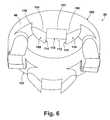
- FIG. 6is a bottom perspective view of a light pipe of the present disclosure.
- FIG. 7is a bottom plan view of the light pipe of FIG. 6 ;
- FIG. 8is a side elevational view of the light pipe of FIG. 6 ;
- FIG. 9is bottom perspective view of a light pipe cap of the present disclosure.
- FIG. 10is a front elevational view of the light pipe cap of FIG. 9 ;
- FIG. 11is a bottom plan view of the light pipe cap of FIG. 9 ;
- FIG. 12is a top plan view of a cap/circuit board assembly of the present disclosure.
- FIG. 13is a cross sectional elevational view taken at section 13 of FIG. 12 ;
- FIG. 14is a cross sectional elevational view taken at section 14 of FIG. 12 ;
- FIG. 15is a cross sectional elevational view of surface 92 of FIG. 8 ;
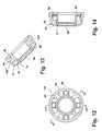
- FIG. 16is a front elevational view of an imager assembly according to a further embodiment of the present disclosure.
- FIG. 17is a front elevational view of an imager head of the imager assembly of FIG. 16 ;
- FIG. 18is a front elevational view of a tapered light pipe of the imager assembly of FIG. 16 ;
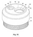
- FIG. 19is a front perspective view of an imager end cap for the image assembly of FIG. 16 ;
- FIG. 20is a cross sectional front elevational view taken at section 20 of Figure.
- FIG. 21is a cross sectional front elevational view taken at area 21 of FIG. 20 .
- housing connection sub-assembly 18includes a first ferrule 26 which is slidably received and pressed into frictional engagement with a male connector 28 .
- a multiple pin electrical connector 30is provided which includes a plurality of pins which provide connection points for the multiple individual wires of a wiring harness 32 which is received through each of first ferrule 26 and male connector 28 .
- a seal 34such as an elastic O-ring is also provided to act as an environmental seal member between male connector 28 and display housing 12 (shown in FIG. 1 ).
- a fastener 36such as a set screw is also provided to frictionally engage the multiple pin electrical connector 30 within male connector 28 .
- Wiring harness 32provides multiple wires which pass through first ferrule 26 into a longitudinal cavity of flexible tube 16 and exit through a second ferrule 38 which is press fit into an imager body 40 .
- Imager assembly 13includes imager head sub-assembly 14 which is retained by imager end cap 24 threadably engaged to imager body 40 .
- Imager head sub-assembly 14includes second ferrule 38 , imager body 40 and each of a circuit board retainer 42 , a circuit board assembly 44 having an imager device 46 fixed thereto, a plurality of electrically conductive pins 48 , a lens receiving unit 50 , a gasket seal 52 such as an O-ring, a lens assembly 54 , and a light source circuit board 56 having at least one and in at least one embodiment four (4) high intensity light emitting diodes (LEDs) 58 equidistantly spaced from each other in a circular pattern.
- a molded light dispersal unit or light pipe unit 60is positioned proximate to (above as shown in FIG.
- circuit board 56to receive and diffuse light transmitted by LEDs 58 .
- Light pipe unit 60is held within a light pipe cap 62 , which is also adapted to hold a sapphire window 64 which receives reflected light for focusing using a lens of lens assembly 54 onto imager device 46 .
- Imager end cap 24is threadably received on a free end of imager body 40 after the components of imager head sub-assembly 14 are installed. Wiring connections are also made between the individual wires of wiring harness 32 and circuit board assembly 44 .
- High intensity light emitting diodes (LEDs) 58produce light from energy received through circuit board 56 to illuminate an area in a viewing range of lens assembly 54 and imager device 46 .
- the illuminated image received by imager device 46can be converted via circuit board assembly 44 to a digital signal and transferred via wiring harness 32 to the image view screen 22 of display housing 12 shown in FIG. 1 .
- the illuminated imagecan also be converted to an analog signal.
- sapphire window 64can be centrally positioned within an interior wall defined by light pipe cap 62 .
- Light pipe unit 60is received in a circular shelf 66 formed in light pipe cap 62 .
- Sapphire window 64is supported in a counterbore 68 extending into a bore 70 of light pipe cap 62 .
- Shelf 66is defined between an inner wall 72 and an outer wall 74 . Light is therefore transmitted throughout the donut or toroid shape of light pipe unit 60 and the reflected (image containing) light is received through sapphire window 64 .
- an imager head sub-assembly 14provides a configuration having lens assembly 54 threadably engaged within lens receiving unit 50 .
- Lens receiving unit 50provides support for circuit board 56 .
- Circuit board 56in turn provides support for inner wall 72 of light pipe cap 62 , while an interface between outer wall 74 of light pipe cap 62 and imager body 40 is sealed using gasket seal 52 .
- the LEDs 58are aligned on circuit board 56 to transmit light generated by the LEDs 58 through the body of light pipe unit 60 as light rays “B” shown in FIG. 5 .
- Light transmitted by LEDs 58 and reflected by an object (not shown) and received through sapphire window 64is digitally transmissible through lens assembly 54 using imager device 46 to circuit board assembly 44 , which is retained at least partially within circuit board retainer 42 .
- light pipe unit 60includes a toroidal wall 76 which is received in shelf 66 of light pipe cap 62 .
- Toroidal wall 76has a dimensionally controlled width “A” which promotes contact between a first face 78 to an outward facing surface 80 of inner wall 72 , and a second face 82 to an inward facing surface 84 of outer wall 74 .
- Contactis maintained for first and second faces 78 , 82 to minimize moisture/dirt intrusion. According to several embodiments contact made by first and second faces 78 , 82 eliminates the need for a sealant or adhesive at these locations.
- Toroidal wall 76has a curved upper surface 92 whose geometry is adapted to closely match a curvature of an outer surface 94 of outer wall 74 which is also adapted to closely match a curvature of an outward facing surface 96 of imager end cap 24 .
- light pipe unit 60can be molded or formed from a polymeric material to create a tubular ring 98 having first and second opposed surfaces 100 , 102 .
- a plurality of raised portions 103are created to match a quantity of LEDs 58 .
- Each raised portion 103includes first and second extending portions 104 , 106 , individually having a first and second curved end surface 108 , 110 defining a free end of the first and second extending portions 104 , 106 respectively.
- a slot 112is created in each raised portion 103 adapted to allow one of the LEDs 58 to be received within the slot 112 .
- Each slot 112is defined by opposed first and second slot walls 114 , 116 , and a slot end wall 118 .
- Each of the first and second extending portions 104 , 106can have a rounded end 120 which extends from second surface 102 to intersect either curved end surface 108 or 110 .
- Light generated by each LED 58enters the raised portion 103 through opposed slot walls 114 , 116 , and slot end wall 118 .
- the geometry of curved end surfaces 108 , 110is adapted to maximize diffusion/transmission of light through raised portions 103 and tubular ring 98 .
- light pipe unit 60can be constructed using a molding process such as injection or insert molding from a polymeric material to create a transparent body having tubular-shaped ring 98 and at least one raised portion 103 homogenously joined to the tubular ring 98 .
- the at least one raised portion 103includes a slot 112 created between opposed first and second extending portions 104 , 106 having an end wall 118 and opposed first and second slot walls 114 , 116 which can be oriented perpendicular to end wall 118 .
- the rounded end face 108 , 110defines a free end of each of the first and second extending portions 104 , 106 and face away from, or outward with respect to the tubular ring 98 .
- tubular ring 68 of light pipe unit 60can have an outer diameter “C” and an inner diameter “D” defined by a through bore 122 , and a total height “E”.
- outer diameter “C”can have a range of approximately 12.6 mm to 12.7 mm
- inner diameter “D”can have a range of approximately 8.7 mm to 8.8 mm
- total height “E”can have a range of approximately 4.88 mm to 4.98 mm.
- Each slot 112can have a width “F” having a range of approximately 2.81 mm to 2.91 mm
- tubular ring 98can have a thickness “G” having a range of approximately 2.28 mm to 2.38 mm.
- the dimensions give hereinare exemplary only and can vary at the discretion of the manufacturer.
- Curved end surfaces 108 , 110can define a convex shaped surface have a radius of curvature.
- Slot end walls 118can be substantially flat or according to several embodiments can define a convex shape facing away from tubular ring 98 having a radius of curvature.
- An apex 124is created at the junction of either slot wall 114 or slot wall 116 with curved end surface 108 or 110 , respectively, which can define a sharp corner adapted to minimize the surface area of light pipe unit 60 in contact with circuit board 56 and to maximize the surface areas of first and second curved end surfaces 108 , 110 which receive and therefore diffuse light radially transmitted from LEDs 58 or reflected from upper surface 88 of circuit board 56 .
- an under or lower surface of light pipe cap 62provides a plurality of lands 126 which structurally join the inner wall 72 to the outer wall 74 .
- a plurality of curved bores 128are provided between each of the lands 126 .
- Curved bores 128are provided to receive individual ones of the raised portions 103 of the light pipe unit 60 .
- the geometry of curved bores 128therefore closely matches the geometry of the individual raised portions 103 of the light pipe unit 60 so that a sealant is not required to be inserted between the individual raised portions 103 and the walls defined by the curved bores 128 .
- An inner flange wall 130is also created which has a diameter substantially matching that of an outer diameter of the light source circuit board 56 shown in reference to FIG. 5 when light pipe cap 62 is assembled together with light source circuit board 56 .
- light pipe cap 62further defines a wall end face 132 from which inner wall 72 extends beyond.
- a wall perimeter surface 134is provided for outer wall 74 .
- a flange surface 136is provided as an outward facing surface opposed to inner flange wall 130 shown in FIG. 9 .
- light pipe cap 62is adapted to provided for lands 126 shown as land 126 ′, 126 ′′, 126 ′′′ and 126 ′′′′.
- a quantity of four bores 128is also provided shown as curved bores 128 ′, 128 ′′, 128 ′′′, and 128 ′′′′.
- Each of the curved bores 128 and the lands 126are equidistantly spaced from each other.
- at least one and in several embodiments a plurality of clearance apertures 138can be provided in individual ones of the lands 126 .
- a single clearance aperture 138is provided in lands 126 ′′.
- Clearance apertures 138are provided to receive an alignment pin (not shown) to rotationally orient the light pipe cap 62 .
- Clearance apertures 138can also be used for passage of electrical wires if necessary.
- a cap/circuit board assembly 140shows an exemplary orientation of light pipe cap 62 with respect to the plurality of LEDs 58 .
- Each of the LEDs 58are oriented to centrally align with individual ones of the curved bores 128 of light pipe cap 62 .
- the light pipe unit 60is shown assembled into light pipe cap 62 together with sapphire window 64 .
- Light source circuit board 56is also shown positioned within the inner flange wall 130 defined by light pipe cap 62 .
- Each of the curved upper surfaces 92 of light pipe cap 62are shown positioned between the inner and outer walls 72 , 74 of light pipe cap 62 .
- the upper surface 88 of light source circuit board 56abuts individual ones of the lands 126 in the assembled position of light source circuit board 56 .
- each of the raised portions 103 of the transparent light pipe unit 60further includes a first apex 124 created at a junction of the first slot wall 114 and the first rounded end face 108 and a second apex 124 created at a junction of the second slot wall 116 and the second rounded end face 110 .
- the first and second apexes 124are positioned in contact with the circuit board 56 with one of the light emitting diodes 58 positioned within the slot 112 . According to other embodiments, the apexes 124 can be positioned proximate to, but not in direct contact with the circuit board 56 .
- curved upper surface 92can be defined by two or more individual curved surface portions.
- a first curve portion 142has a first radius of curvature 144 and a second curve portion 146 has a second radius of curvature 148 .
- First and second radius of curvatures 144 , 148can be equal or different from each other.
- the difference in curvature between the first and second curve portion 142 , 146can be optimized to maximize the focal length of the light transmitted through light pipe unit 60 to a distance selected by the manufacturer.
- Light pipe units 60 of the present disclosureprovide several advantages. By creating the slot 112 between first and second slot walls 112 , 114 , the light pipe unit 60 can be positioned to provide transparent material in contact with, or in close proximity to the exposed surfaces of the LEDs 58 . This permits a greater amount of light from the LEDs 58 to be captured and transmitted via the light pipe unit 60 . By creating apexes where the first and second slot walls 112 , 114 meet the curved end surfaces 108 , 110 , contact between the light pipe unit 60 and the circuit board can be minimized.
- the curved end surfaces 108 , 110also promote reflection of light emitted from the LEDs 58 that is not parallel or co-axial with the raised portions 103 to be redirected outwardly from the light pipe unit 60 , increasing the total light emission.
- Using two or more curve portions 142 , 146 each having a different radius of curvaturefurther promotes transmission of reflected light from the LEDs 58 .
- an imager assembly 150can include an imager head sub-assembly 152 which is flexibly connected to a housing connection sub-assembly 154 using a flexible tube 16 ′.
- Imager head sub-assembly 152includes an imager body 156 which is connected to the flexible tube 16 ′ using a connection ferrule 158 .
- An imager end cap 160is threadably connected at an opposite end of imager body 156 with respect to the connection ferrule 158 , and a tapered light pipe 162 is retained in the imager end cap 160 .
- imager head sub-assembly 152includes a light pipe mounting cavity 164 adapted to receive the tapered light pipe 162 .
- Light pipe mounting cavity 164is created in a raised portion 166 of imager end cap 160 .
- a lens 168such as a sapphire lens is also retained in imager end cap 160 in a lens mounting cavity 170 . Similar to previous embodiments, light emitted through tapered light pipe 162 and reflected off a remote object (not shown) is received in lens 168 .
- tapered light pipe 162defines a homogeneous molded polymeric material part which can be made using a material such as a transparent acrylic plastic.
- Tapered light pipe 162includes a conical shaped perimeter wall 172 defining a light pipe body 174 extending from a first body end 176 which has a minimum body diameter “H” to a second body end or body junction 177 which has a maximum body diameter “H′”. From the second body end or body junction 177 , a transition portion 178 can extend oppositely with respect to first body end 176 and can be formed as shown having a conical shape or can also be formed having a radius at the discretion of the designer. Transition portion 178 homogeneously connects to a flange portion 180 .
- Flange portion 180extends outwardly with respect to a light pipe longitudinal axis 184 to a flange perimeter wall 182 .
- flange portion 180is generally oriented transversely with respect to light pipe longitudinal axis 184 and flange perimeter wall 182 is oriented parallel to light pipe longitudinal axis 184 .
- a convex curved surface 185includes first and second arc portions 186 , 188 , the first arc portion 186 having a radius of curvature X 1 larger than a radius of curvature X 2 of the second arc portion 188 .
- the second arc portion 188tangentially meets the flange perimeter wall 182 of flange portion 180 .
- Convex curved surface 185connects opposed faces of flange perimeter wall 182 and extends oppositely (upwardly as viewed in FIG. 18 ) with respect to first body end 176 .
- Second arc portion 188smoothly transitions into first arc portion 186 .
- First arc portion 186 at its intersection with longitudinal axis 184 and measured from first body end 176defines a total height “K” of tapered light pipe 162 .
- Flange perimeter wall 182has a flange thickness “L”.
- Flange portion 180extends radially outward from either or both body junction 177 and transition portion 178 to define a flange mount surface 190 which faces in a similar direction to first body end 176 .
- Flange mount surface 190is substantially planar, is oriented transverse to light pipe longitudinal axis 184 , and extends from a furthest outward extension of either transition portion 178 or the body second end (at body junction 177 ) by an extension dimension “Y”.
- flange portion 180is circular having a flange diameter “M”.
- Flange diameter “M”is larger than second end maximum diameter “H′” to create flange mount surface 190 .
- flange perimeter wall 182can also define additional geometric shapes including but not limited to oval, rectilinear, and multi-facetted, with the geometry of convex curved surface 185 adjusted accordingly.
- imager end cap 160includes a cap body 192 which is substantially circular in shape having a threaded body portion 194 extending axially with respect to cap body 192 .
- An arc shaped surface 196extends inwardly from the perimeter wall of cap body 192 and has raised portion 166 extending outwardly therefrom.
- Light pipe mounting cavity 164can further include a counterbore seating surface 198 which is adapted to receive flange mount surface 190 of tapered light pipe 162 which will be shown and described in greater detail in reference to FIGS. 20 and 21 .
- Inwardly directed from counterbore seating surface 198is a chamfer 200 which transitions into a through bore 202 .
- Lens mounting cavity 170is similarly configured, having a counterbore seating surface 204 and a through bore 206 centrally disposed with respect to counterbore seating surface 204 .
- tapered light pipe 162is shown during installation into imager end cap 160 with respect to further components of imager head sub-assembly 152 .
- the flange portion 180 of tapered light pipe 162is shown positioned partially within the light pipe mounting cavity 164 just prior to contact between flange portion 180 and counterbore seating surface 198 .
- Light pipe body 174is freely positioned within through-bore 202 and additionally freely positioned within a recessed cavity 208 and a clearance cavity 210 also created within imager end cap 160 . No portion of light pipe body 174 contacts any feature of imager end cap 160 .
- a clearance gap 212is also maintained when tapered light pipe 162 is fully seated with respect to counterbore seating surface 198 such that there is no physical contact between first body end 176 of tapered light pipe 162 and a light emitting diode (LED) 214 which is connected to a circuit board 216 .
- LEDlight emitting diode
- LED 214Light emitted by LED 214 is transmitted through clearance gap 212 and into first body end 176 to be emitted in a plurality of dispersion paths “N” via convex curved surface 185 .
- the clearance gap 212is fixed when threaded body portion 194 of imager end cap 160 is fully threadably engaged with imager body 156 , thereby also fixing a position of circuit board 216 with respect to both imager end cap 160 and imager body 156 .
- lens 168is also fixed within lens mounting cavity 170 such that reflected light received in a receiving path “P” through lens 168 is directed through a lens assembly 218 to be received by an imager device 220 also fixedly connected to circuit board 216 .
- tapered light pipe 162is shown in a fully seated position with respect to imager end cap 160 and LED 214 .
- the installed or fully seated position of tapered light pipe 162is reached when flange mount surface 190 physically contacts counterbore seating surface 198 .
- the only direct physical contact between tapered light pipe 162 and imager end cap 160 and/or imager head sub-assembly 152occurs at the surface contact between flange mount surface 190 and counterbore seating surface 198 . This minimizes the potential paths for light transmitted through tapered light pipe 162 diffracting into and reflecting off the interior surfaces of imager end cap 160 .
- a clearance gap “R”is maintained between a cavity wall 222 of light pipe mounting cavity 164 and flange perimeter wall 182 , defining a separation space 224 .
- An adhesive 226is applied to fill the separation space 224 , using only a minimum amount of adhesive 226 to fill the separation space 224 without the adhesive 226 contacting any other portion of tapered light pipe 162 .
- chamfer 200 of imager end cap 160defines a different angle with respect to light pipe longitudinal axis 184 than an angle defined by transition portion 178 with respect to longitudinal axis 184 , so that no contact occurs between transition portion 178 and chamfer 200 .
- a gap spacing dimension “Q” defined by the clearance gap 212 between first body end 176 and LED 214is maintained in the seated position of tapered light pipe 162 .
- Gap spacing dimension “Q”is maintained as a positive value such that clearance between first body end 176 of tapered light pipe 162 and LED 214 is always provided.
- light pipe longitudinal axis 184is substantially coaxially aligned with a longitudinal axis of LED 214 to maximize the light admitted by LED 214 being transmitted through tapered light pipe 162 .
- Light which is reflected within recessed cavity 208 and clearance cavity 210can also enter tapered light pipe 162 through conical shaped perimeter wall 172 .
- Tapered light pipes of the present disclosureoffer several advantages. These include the use of a flange portion extending radially outward with respect to a conical shaped perimeter wall, which permits the tapered light pipe 162 to be mounted at the flange portion, minimizing the amount of light reflection within the imager end cap 160 . Also, by maintaining clearance gap “R” between flange perimeter wall 182 and cavity wall 222 , the use of adhesive 226 to fill the clearance gap “R” defines the only required sealing point between tapered light pipe 162 and imager end cap 160 . Adhesive 226 is applied at a position which also environmentally seals the components within imager head sub-assembly 152 from moisture and dirt, and does not impact light transmission through tapered light pipe 162 .
- the light dispersion angle for tapered light pipe 162can be modified at the discretion of the designer. Further, by maintaining the orientation of flange mount surface 190 substantially perpendicular with respect to light pipe longitudinal axis 184 , and orienting the counterbore seating surface 198 of imager end cap 160 also substantially transverse with respect to light pipe longitudinal axis 184 , co-axial orientation of tapered light pipe 162 and LED 214 can be provided.
- transition portion 178can also be formed as a radius at the discretion of the designer to suit a mold used to create tapered light pipe 162 . Transition portion 178 can also be eliminated entirely, having body junction 177 in direct contact with flange portion 180 . The geometry or use of chamfer 200 can therefore also be modified, or chamfer 200 can also be eliminated at the discretion of the designer.
- homogeneous(ly)as used herein is defined as a part, component, member, or the like (collectively the part) having all portions and/or connections of the part formed of the same material and by the same process used to create the part, such as by molding including injection molding, or casting, such that no portion(s) or connections of the part require connection to any other portion by a secondary process including but not limited to welding, adhesive bonding, mechanical connection, second molding or casting process, or the like, and the chemical properties of the part material are substantially equivalent throughout the part.
Landscapes
- Physics & Mathematics (AREA)
- Engineering & Computer Science (AREA)
- Multimedia (AREA)
- General Physics & Mathematics (AREA)
- Signal Processing (AREA)
- Astronomy & Astrophysics (AREA)
- Optics & Photonics (AREA)
- Life Sciences & Earth Sciences (AREA)
- Health & Medical Sciences (AREA)
- Chemical & Material Sciences (AREA)
- Analytical Chemistry (AREA)
- Biochemistry (AREA)
- General Health & Medical Sciences (AREA)
- Immunology (AREA)
- Pathology (AREA)
- Studio Devices (AREA)
Abstract
Description
Claims (23)
Priority Applications (1)
| Application Number | Priority Date | Filing Date | Title |
|---|---|---|---|
| US12/564,447US8760507B2 (en) | 2008-08-05 | 2009-09-22 | Light pipe for imaging head of video inspection device |
Applications Claiming Priority (2)
| Application Number | Priority Date | Filing Date | Title |
|---|---|---|---|
| US12/186,182US20100033986A1 (en) | 2008-08-05 | 2008-08-05 | Light Pipe For Imaging Head of Video Inspection Device |
| US12/564,447US8760507B2 (en) | 2008-08-05 | 2009-09-22 | Light pipe for imaging head of video inspection device |
Related Parent Applications (1)
| Application Number | Title | Priority Date | Filing Date |
|---|---|---|---|
| US12/186,182Continuation-In-PartUS20100033986A1 (en) | 2008-08-05 | 2008-08-05 | Light Pipe For Imaging Head of Video Inspection Device |
Publications (2)
| Publication Number | Publication Date |
|---|---|
| US20100033563A1 US20100033563A1 (en) | 2010-02-11 |
| US8760507B2true US8760507B2 (en) | 2014-06-24 |
Family
ID=41652535
Family Applications (1)
| Application Number | Title | Priority Date | Filing Date |
|---|---|---|---|
| US12/564,447Expired - Fee RelatedUS8760507B2 (en) | 2008-08-05 | 2009-09-22 | Light pipe for imaging head of video inspection device |
Country Status (1)
| Country | Link |
|---|---|
| US (1) | US8760507B2 (en) |
Cited By (1)
| Publication number | Priority date | Publication date | Assignee | Title |
|---|---|---|---|---|
| US20150041165A1 (en)* | 2011-11-25 | 2015-02-12 | Campbell Alan Booth | Method and Apparatus for Navigating Longitudinal Bores |
Families Citing this family (20)
| Publication number | Priority date | Publication date | Assignee | Title |
|---|---|---|---|---|
| GB2470327B (en)* | 2008-03-07 | 2012-03-21 | Milwaukee Electric Tool Corp | Visual inspection device |
| US20110228076A1 (en)* | 2010-03-17 | 2011-09-22 | Da-Ming Liu | Multifunctional monitoring apparatus |
| US9049351B2 (en)* | 2010-05-03 | 2015-06-02 | Inspectron, Inc. | Insulator design for video inspection devices |
| GB2485767B (en)* | 2010-11-19 | 2015-02-18 | Ev Offshore Ltd | Optical element |
| CN102563069A (en)* | 2010-12-22 | 2012-07-11 | 中国航空工业集团公司沈阳发动机设计研究所 | Quick-release self-locking plug device |
| TWM411574U (en)* | 2010-12-31 | 2011-09-11 | xiang-de Zeng | Industrial hard-tube erect-type endoscope |
| US8633980B2 (en)* | 2011-03-18 | 2014-01-21 | Da-Ming Liu | Monitoring apparatus having a detachable display and a power failure protection |
| HK1198738A1 (en) | 2011-05-03 | 2015-06-05 | Endosee股份有限公司 | Method and apparatus for hysteroscopy and endometrial biopsy |
| USD668567S1 (en)* | 2011-05-09 | 2012-10-09 | Emerson Electric Co. | Display housing for handheld inspection device |
| USD668566S1 (en)* | 2011-05-09 | 2012-10-09 | Emerson Electric Co. | Display housing for a handheld inspection device |
| USD679616S1 (en)* | 2011-05-13 | 2013-04-09 | Yingjie Sun | Digital inspection camera |
| US9468367B2 (en) | 2012-05-14 | 2016-10-18 | Endosee Corporation | Method and apparatus for hysteroscopy and combined hysteroscopy and endometrial biopsy |
| US9622646B2 (en) | 2012-06-25 | 2017-04-18 | Coopersurgical, Inc. | Low-cost instrument for endoscopically guided operative procedures |
| US9736342B2 (en) | 2012-10-19 | 2017-08-15 | Milwaukee Electric Tool Corporation | Visual inspection device |
| US9307672B2 (en)* | 2013-08-26 | 2016-04-05 | General Electric Company | Active cooling of inspection or testing devices |
| USD811459S1 (en)* | 2015-12-29 | 2018-02-27 | Ningbo Hi-Tech Zone Cvs Borescope Tech Co., Ltd. | Borescope |
| US10702305B2 (en) | 2016-03-23 | 2020-07-07 | Coopersurgical, Inc. | Operative cannulas and related methods |
| EP3691510A4 (en) | 2017-10-04 | 2021-06-09 | Duke University | COLPOSCOPES, MAMMOSCOPES, AND INSERTION AIDS WITH CURVED ENDS AND RELATED PROCEDURES |
| US12073559B2 (en) | 2018-10-04 | 2024-08-27 | Duke University | Methods for automated detection of cervical pre-cancers with a low-cost, point-of-care, pocket colposcope |
| US11278360B2 (en)* | 2018-11-16 | 2022-03-22 | Globus Medical, Inc. | End-effectors for surgical robotic systems having sealed optical components |
Citations (100)
| Publication number | Priority date | Publication date | Assignee | Title |
|---|---|---|---|---|
| US3748483A (en)* | 1970-12-17 | 1973-07-24 | Svenska Dataregister Ab | Indicating device for use in optical data sensing equipment |
| US4469398A (en)* | 1981-10-27 | 1984-09-04 | Oximetrix, Inc. | Optical connector for use during photometric analysis |
| US4595265A (en) | 1983-04-04 | 1986-06-17 | Hodgson R W | Portable field inspection microscope for inspecting a butt end of a cylindrical object, such as a fiber optics cable |
| US4805984A (en)* | 1985-11-21 | 1989-02-21 | Minnesota Mining And Manufacturing Company | Totally internally reflecting light conduit |
| US5373317A (en)* | 1993-05-28 | 1994-12-13 | Welch Allyn, Inc. | Control and display section for borescope or endoscope |
| US5416638A (en)* | 1992-02-06 | 1995-05-16 | Linvatec Corporation | Disposable endoscope |
| US5506929A (en) | 1994-10-19 | 1996-04-09 | Clio Technologies, Inc. | Light expanding system for producing a linear or planar light beam from a point-like light source |
| US5527261A (en)* | 1994-08-18 | 1996-06-18 | Welch Allyn, Inc. | Remote hand-held diagnostic instrument with video imaging |
| US5531664A (en) | 1990-12-26 | 1996-07-02 | Olympus Optical Co., Ltd. | Bending actuator having a coil sheath with a fixed distal end and a free proximal end |
| US5555161A (en) | 1995-09-11 | 1996-09-10 | Delco Electronics Corporation | Bi-functional light pipe and display assembly |
| US5633675A (en)* | 1993-02-16 | 1997-05-27 | Welch Allyn, Inc, | Shadow probe |
| US5651047A (en) | 1993-01-25 | 1997-07-22 | Cardiac Mariners, Incorporated | Maneuverable and locateable catheters |
| US5662586A (en)* | 1994-08-18 | 1997-09-02 | Welch Allyn, Inc. | Hand held diagnostic instrument with video imaging |
| US5745165A (en)* | 1995-06-08 | 1998-04-28 | Matsushita Electric Industrial Co., Ltd. | Video scope camera |
| US5880826A (en) | 1997-07-01 | 1999-03-09 | L J Laboratories, L.L.C. | Apparatus and method for measuring optical characteristics of teeth |
| US5879288A (en)* | 1992-11-25 | 1999-03-09 | Olympus Optical Co., Ltd. | Endoscope system including both reusable-type and cover-type endoscopes |
| US5926262A (en) | 1997-07-01 | 1999-07-20 | Lj Laboratories, L.L.C. | Apparatus and method for measuring optical characteristics of an object |
| US5986746A (en) | 1994-02-18 | 1999-11-16 | Imedge Technology Inc. | Topographical object detection system |
| US6031566A (en) | 1996-12-27 | 2000-02-29 | Olympus America Inc. | Method and device for providing a multiple source display and a remote visual inspection system specially adapted for use with the device |
| US6091453A (en) | 1996-07-29 | 2000-07-18 | Coan; Steven | Hand held remote camera |
| US6106457A (en) | 1997-04-04 | 2000-08-22 | Welch Allyn, Inc. | Compact imaging instrument system |
| US6118521A (en) | 1996-01-02 | 2000-09-12 | Lj Laboratories, L.L.C. | Apparatus and method for measuring optical characteristics of an object |
| US6186944B1 (en) | 1998-11-25 | 2001-02-13 | Jory Tsai | Medical inspection device |
| US6188471B1 (en) | 1999-03-05 | 2001-02-13 | Lj Laboratories, L.L.C. | Apparatus and method for measuring optical characteristics of an object |
| US20010000672A1 (en)* | 1997-11-07 | 2001-05-03 | Kiyoko Ooshima | Video scope and portable accommodation case therefor |
| US6319199B1 (en) | 1998-10-26 | 2001-11-20 | David M. Sheehan | Portable data collection device |
| US6332092B1 (en) | 1998-07-08 | 2001-12-18 | Lifespex, Incorporated | Optical probe having and methods for uniform light irradiation and/or light collection over a volume |
| US20020033931A1 (en) | 1999-01-28 | 2002-03-21 | Knox Richard M. | Methods of projecting images |
| US6361489B1 (en) | 1998-11-25 | 2002-03-26 | Jory Tsai | Medical inspection device |
| US6373573B1 (en) | 2000-03-13 | 2002-04-16 | Lj Laboratories L.L.C. | Apparatus for measuring optical characteristics of a substrate and pigments applied thereto |
| US6394355B1 (en) | 1999-02-22 | 2002-05-28 | Symbol Technologies, Inc. | Hand-held acquistion device |
| US6428198B1 (en) | 1998-07-07 | 2002-08-06 | Alliedsignal Inc. | Display system having a light source separate from a display device |
| US20020154510A1 (en) | 2001-02-05 | 2002-10-24 | Li Kenneth K. | Illumination engine for a projection display using a tapered light pipe |
| US6476970B1 (en) | 2000-08-10 | 2002-11-05 | Agilent Technologies, Inc. | Illumination optics and method |
| US6478730B1 (en) | 1998-09-09 | 2002-11-12 | Visionscope, Inc. | Zoom laparoscope |
| US6484050B1 (en) | 1997-11-18 | 2002-11-19 | Care Wise Medical Products Corporation | Minimally invasive surgical instrument for tissue identification, dislodgment and retrieval and methods of use |
| US6487440B2 (en) | 1998-07-08 | 2002-11-26 | Lifespex, Inc. | Optical probe having and methods for difuse and uniform light irradiation |
| US6504985B2 (en) | 1995-06-27 | 2003-01-07 | Lumitex, Inc. | Illuminated surgical retractor |
| US20030063261A1 (en) | 2001-04-25 | 2003-04-03 | Li Kenneth K. | Light recovery for projection displays |
| US20030128341A1 (en) | 2001-08-23 | 2003-07-10 | Li Kenneth K. | Led illumination engine using a reflector |
| US6603874B1 (en) | 1996-11-12 | 2003-08-05 | Robotic Vision Systems, Inc. | Method and system for imaging an object or pattern |
| US6619820B2 (en) | 2000-09-20 | 2003-09-16 | Cogent Light Technologies, Inc. | Light condensing and collecting systems using lensed light pipes |
| US6626825B2 (en) | 1998-11-25 | 2003-09-30 | Jory Tsai | Medical inspection device |
| US6686950B1 (en)* | 1997-09-05 | 2004-02-03 | Michel Caffon | Device for inspecting ventilation or air-conditioning conduits, or other types of conduits |
| US6695775B2 (en)* | 2001-06-07 | 2004-02-24 | Fuji Photo Optical Co., Ltd. | Lens assembly for endoscopic lens system |
| US6819506B1 (en)* | 2003-09-30 | 2004-11-16 | Infinity Trading Co. Ltd. | Optical lens system for projecting light in a lambertion pattern from a high power led light source |
| US20040233655A1 (en) | 2003-05-23 | 2004-11-25 | Scott Moore Zimmerman | Illumination systems utilizing highly reflective light emitting diodes and light recycling to enhance brightness |
| US6831679B1 (en)* | 2000-02-17 | 2004-12-14 | Deepsea Power & Light Company | Video camera head with thermal feedback lighting control |
| US6855106B2 (en)* | 2000-03-16 | 2005-02-15 | Medivision, Inc. | Endoscope and camera mount |
| US6863651B2 (en) | 2001-10-19 | 2005-03-08 | Visionscope, Llc | Miniature endoscope with imaging fiber system |
| US20050063196A1 (en) | 2003-06-09 | 2005-03-24 | Wavien, Inc. | Light pipe based projection engine |
| US6880402B1 (en) | 1999-10-27 | 2005-04-19 | Schlumberger Technology Corporation | Deposition monitoring system |
| US6898353B2 (en) | 2001-05-25 | 2005-05-24 | Wavien, Inc. | Lensed tapered optical waveguide |
| US6896653B1 (en) | 2002-03-07 | 2005-05-24 | Science For Medical Advocates, Inc. | Personal pelvic viewer |
| US20050129108A1 (en)* | 2003-01-29 | 2005-06-16 | Everest Vit, Inc. | Remote video inspection system |
| US6931149B2 (en) | 2002-04-19 | 2005-08-16 | Norsk Elektro Optikk A/S | Pipeline internal inspection device and method |
| US6939009B2 (en) | 2001-02-06 | 2005-09-06 | Optics 1, Inc. | Compact work light with high illumination uniformity |
| US20050213046A1 (en) | 2004-03-26 | 2005-09-29 | Teijido Juan M | Image generation unit |
| US20050218537A1 (en)* | 2004-03-31 | 2005-10-06 | Eastman Kodak Company | Light pipe with molded optical surfaces |
| US6953432B2 (en)* | 2003-05-20 | 2005-10-11 | Everest Vit, Inc. | Imager cover-glass mounting |
| US6957905B1 (en) | 2001-10-03 | 2005-10-25 | Led Pipe, Inc. | Solid state light source |
| US20060061870A1 (en) | 2004-09-17 | 2006-03-23 | Frank Wang | Optical system for a light emitting apparatus |
| US7050245B2 (en)* | 2004-03-11 | 2006-05-23 | Pinotage L.L.C. | Lens assembly and optical imaging using same |
| US20060132910A1 (en) | 2004-11-30 | 2006-06-22 | Barco N.V. | Efficient illumination for display systems and in methods for displaying |
| US7137948B2 (en) | 1998-11-25 | 2006-11-21 | Jory Tsai | Medical inspection device |
| US20060281772A1 (en)* | 2005-06-10 | 2006-12-14 | Nand Baindur | Alkylquinoline and alkylquinazoline kinase modulators |
| US7153015B2 (en) | 2001-12-31 | 2006-12-26 | Innovations In Optics, Inc. | Led white light optical system |
| US20060290899A1 (en) | 2005-06-24 | 2006-12-28 | Davis Michael T | Compact optical engine for very small personal projectors using LED illumination |
| US7178941B2 (en) | 2003-05-05 | 2007-02-20 | Color Kinetics Incorporated | Lighting methods and systems |
| US7209624B2 (en)* | 2004-01-28 | 2007-04-24 | Eastman Kodak Company | Apparatus and method for illumination of light valves |
| US7261453B2 (en) | 2005-01-25 | 2007-08-28 | Morejon Israel J | LED polarizing optics for color illumination system and method of using same |
| US7261438B2 (en)* | 2002-06-20 | 2007-08-28 | Eveready Battery Company, Inc. | Lighting device with adjustable spotlight beam |
| US20070208312A1 (en)* | 2006-03-03 | 2007-09-06 | Axcess Instruments, Inc. | Apparatus and method for minimally invasive surgery |
| US20070258049A1 (en) | 2006-05-04 | 2007-11-08 | Vesselin Shaoulov | Systems and methods for providing compact illumination in head mounted displays |
| US20070263298A1 (en) | 2006-05-09 | 2007-11-15 | Ostendo Technologies, Inc. | LED-based high efficiency illumination systems for use in projection systems |
| US7306559B2 (en) | 1997-07-02 | 2007-12-11 | Lumitex, Inc. | Illuminated surgical retractor |
| US7306352B2 (en) | 2004-10-19 | 2007-12-11 | Samsung Electronics Co., Ltd. | Illuminator |
| US20070291505A1 (en) | 2006-06-02 | 2007-12-20 | Rance Fortenberry | Light source assembly with integrated optical pipe |
| US20070291491A1 (en) | 2006-06-13 | 2007-12-20 | Li Kenneth K | Illumination system and method for recycling light to increase the brightness of the light source |
| US7317506B2 (en) | 2005-03-29 | 2008-01-08 | Asml Netherlands B.V. | Variable illumination source |
| US20080018999A1 (en) | 2006-07-18 | 2008-01-24 | Colorlink, Inc. | Light collectors for projection systems |
| US20080030974A1 (en) | 2006-08-02 | 2008-02-07 | Abu-Ageel Nayef M | LED-Based Illumination System |
| US7333083B1 (en) | 2001-05-10 | 2008-02-19 | Logitech Europe S.A. | Optical based performance improvement for an optical illumination configuration |
| US7338187B2 (en) | 2002-06-21 | 2008-03-04 | Wavien, Inc. | Multiple lamp illumination system |
| US7339735B2 (en) | 2000-08-24 | 2008-03-04 | Wavien, Inc. | Polarization recovery system for projection displays |
| US7350928B2 (en)* | 2004-11-15 | 2008-04-01 | Young Optics Inc. | Projection display system |
| US7357518B2 (en)* | 2004-06-03 | 2008-04-15 | Seiko Epson Corporation | Projector |
| US20080123343A1 (en) | 2006-06-23 | 2008-05-29 | Tatsuru Kobayashi | Light source device, image display device, optical element and manufacturing method thereof |
| US7410283B2 (en)* | 2002-11-19 | 2008-08-12 | Den-Mat Holdings Llc | Dental light guide |
| US7413543B2 (en)* | 2003-04-01 | 2008-08-19 | Scimed Life Systems, Inc. | Endoscope with actively cooled illumination sources |
| US7419467B2 (en) | 1998-11-25 | 2008-09-02 | M3 Electronics, Inc. | Medical inspection device |
| US7424197B2 (en) | 1992-03-23 | 2008-09-09 | 3M Innovative Properties Company | Luminaire device |
| US7445340B2 (en) | 2005-05-19 | 2008-11-04 | 3M Innovative Properties Company | Polarized, LED-based illumination source |
| US7451917B2 (en) | 2002-01-11 | 2008-11-18 | Hand Held Products, Inc. | Transaction terminal comprising imaging module |
| US20090046150A1 (en)* | 2007-08-07 | 2009-02-19 | Hitachi, Ltd. | Vehicle Camera System |
| US20090109283A1 (en)* | 2007-10-26 | 2009-04-30 | Joshua Lynn Scott | Integrated storage for industrial inspection handset |
| US7874714B2 (en)* | 2005-07-29 | 2011-01-25 | Ccs, Inc. | Optical unit and light irradiating device |
| US7885010B1 (en)* | 2008-01-14 | 2011-02-08 | Integrated Medical Systems International | Endoscope objective lens and method of assembly |
| US7962023B2 (en)* | 2008-07-03 | 2011-06-14 | Samsung Electronics Co., Ltd | Image stabilizer |
| US8118733B2 (en)* | 2006-12-22 | 2012-02-21 | Ge Inspection Technologies, Lp | Heat protection systems and methods for remote viewing devices |
- 2009
- 2009-09-22USUS12/564,447patent/US8760507B2/ennot_activeExpired - Fee Related
Patent Citations (122)
| Publication number | Priority date | Publication date | Assignee | Title |
|---|---|---|---|---|
| US3748483A (en)* | 1970-12-17 | 1973-07-24 | Svenska Dataregister Ab | Indicating device for use in optical data sensing equipment |
| US4469398A (en)* | 1981-10-27 | 1984-09-04 | Oximetrix, Inc. | Optical connector for use during photometric analysis |
| US4595265A (en) | 1983-04-04 | 1986-06-17 | Hodgson R W | Portable field inspection microscope for inspecting a butt end of a cylindrical object, such as a fiber optics cable |
| US4805984A (en)* | 1985-11-21 | 1989-02-21 | Minnesota Mining And Manufacturing Company | Totally internally reflecting light conduit |
| US5531664A (en) | 1990-12-26 | 1996-07-02 | Olympus Optical Co., Ltd. | Bending actuator having a coil sheath with a fixed distal end and a free proximal end |
| US5416638A (en)* | 1992-02-06 | 1995-05-16 | Linvatec Corporation | Disposable endoscope |
| US7424197B2 (en) | 1992-03-23 | 2008-09-09 | 3M Innovative Properties Company | Luminaire device |
| US5879288A (en)* | 1992-11-25 | 1999-03-09 | Olympus Optical Co., Ltd. | Endoscope system including both reusable-type and cover-type endoscopes |
| US5651047A (en) | 1993-01-25 | 1997-07-22 | Cardiac Mariners, Incorporated | Maneuverable and locateable catheters |
| US5633675A (en)* | 1993-02-16 | 1997-05-27 | Welch Allyn, Inc, | Shadow probe |
| US5373317A (en)* | 1993-05-28 | 1994-12-13 | Welch Allyn, Inc. | Control and display section for borescope or endoscope |
| US5373317B1 (en)* | 1993-05-28 | 2000-11-21 | Welch Allyn Inc | Control and display section for borescope or endoscope |
| US5986746A (en) | 1994-02-18 | 1999-11-16 | Imedge Technology Inc. | Topographical object detection system |
| US5662586A (en)* | 1994-08-18 | 1997-09-02 | Welch Allyn, Inc. | Hand held diagnostic instrument with video imaging |
| US5527261A (en)* | 1994-08-18 | 1996-06-18 | Welch Allyn, Inc. | Remote hand-held diagnostic instrument with video imaging |
| US5668913A (en) | 1994-10-19 | 1997-09-16 | Tai; Ping-Kaung | Light expanding system for producing a linear or planar light beam from a point-like light source |
| US5506929A (en) | 1994-10-19 | 1996-04-09 | Clio Technologies, Inc. | Light expanding system for producing a linear or planar light beam from a point-like light source |
| US5745165A (en)* | 1995-06-08 | 1998-04-28 | Matsushita Electric Industrial Co., Ltd. | Video scope camera |
| US6504985B2 (en) | 1995-06-27 | 2003-01-07 | Lumitex, Inc. | Illuminated surgical retractor |
| US5555161A (en) | 1995-09-11 | 1996-09-10 | Delco Electronics Corporation | Bi-functional light pipe and display assembly |
| US6118521A (en) | 1996-01-02 | 2000-09-12 | Lj Laboratories, L.L.C. | Apparatus and method for measuring optical characteristics of an object |
| US6091453A (en) | 1996-07-29 | 2000-07-18 | Coan; Steven | Hand held remote camera |
| US20030215127A1 (en) | 1996-11-12 | 2003-11-20 | Howard Stern | Method and system for imaging an object or pattern |
| US6603874B1 (en) | 1996-11-12 | 2003-08-05 | Robotic Vision Systems, Inc. | Method and system for imaging an object or pattern |
| US6031566A (en) | 1996-12-27 | 2000-02-29 | Olympus America Inc. | Method and device for providing a multiple source display and a remote visual inspection system specially adapted for use with the device |
| US6106457A (en) | 1997-04-04 | 2000-08-22 | Welch Allyn, Inc. | Compact imaging instrument system |
| US5926262A (en) | 1997-07-01 | 1999-07-20 | Lj Laboratories, L.L.C. | Apparatus and method for measuring optical characteristics of an object |
| US5880826A (en) | 1997-07-01 | 1999-03-09 | L J Laboratories, L.L.C. | Apparatus and method for measuring optical characteristics of teeth |
| US7306559B2 (en) | 1997-07-02 | 2007-12-11 | Lumitex, Inc. | Illuminated surgical retractor |
| US6686950B1 (en)* | 1997-09-05 | 2004-02-03 | Michel Caffon | Device for inspecting ventilation or air-conditioning conduits, or other types of conduits |
| US20010000672A1 (en)* | 1997-11-07 | 2001-05-03 | Kiyoko Ooshima | Video scope and portable accommodation case therefor |
| US6484050B1 (en) | 1997-11-18 | 2002-11-19 | Care Wise Medical Products Corporation | Minimally invasive surgical instrument for tissue identification, dislodgment and retrieval and methods of use |
| US6428198B1 (en) | 1998-07-07 | 2002-08-06 | Alliedsignal Inc. | Display system having a light source separate from a display device |
| US6332092B1 (en) | 1998-07-08 | 2001-12-18 | Lifespex, Incorporated | Optical probe having and methods for uniform light irradiation and/or light collection over a volume |
| US6487440B2 (en) | 1998-07-08 | 2002-11-26 | Lifespex, Inc. | Optical probe having and methods for difuse and uniform light irradiation |
| US6478730B1 (en) | 1998-09-09 | 2002-11-12 | Visionscope, Inc. | Zoom laparoscope |
| US6319199B1 (en) | 1998-10-26 | 2001-11-20 | David M. Sheehan | Portable data collection device |
| US7419467B2 (en) | 1998-11-25 | 2008-09-02 | M3 Electronics, Inc. | Medical inspection device |
| US6361489B1 (en) | 1998-11-25 | 2002-03-26 | Jory Tsai | Medical inspection device |
| US7137948B2 (en) | 1998-11-25 | 2006-11-21 | Jory Tsai | Medical inspection device |
| US6186944B1 (en) | 1998-11-25 | 2001-02-13 | Jory Tsai | Medical inspection device |
| US6626825B2 (en) | 1998-11-25 | 2003-09-30 | Jory Tsai | Medical inspection device |
| US6379011B1 (en) | 1999-01-28 | 2002-04-30 | Duke University | Methods of projecting images |
| US20020033931A1 (en) | 1999-01-28 | 2002-03-21 | Knox Richard M. | Methods of projecting images |
| US6394355B1 (en) | 1999-02-22 | 2002-05-28 | Symbol Technologies, Inc. | Hand-held acquistion device |
| US6188471B1 (en) | 1999-03-05 | 2001-02-13 | Lj Laboratories, L.L.C. | Apparatus and method for measuring optical characteristics of an object |
| US6886406B1 (en) | 1999-10-27 | 2005-05-03 | Schlumberger Technology Corporation | Downhole deposition monitoring system |
| US6880402B1 (en) | 1999-10-27 | 2005-04-19 | Schlumberger Technology Corporation | Deposition monitoring system |
| US6831679B1 (en)* | 2000-02-17 | 2004-12-14 | Deepsea Power & Light Company | Video camera head with thermal feedback lighting control |
| US6373573B1 (en) | 2000-03-13 | 2002-04-16 | Lj Laboratories L.L.C. | Apparatus for measuring optical characteristics of a substrate and pigments applied thereto |
| US6855106B2 (en)* | 2000-03-16 | 2005-02-15 | Medivision, Inc. | Endoscope and camera mount |
| US6476970B1 (en) | 2000-08-10 | 2002-11-05 | Agilent Technologies, Inc. | Illumination optics and method |
| US6829098B2 (en) | 2000-08-10 | 2004-12-07 | Agilent Technologies, Inc. | Illumination optics and method |
| US7339735B2 (en) | 2000-08-24 | 2008-03-04 | Wavien, Inc. | Polarization recovery system for projection displays |
| US6619820B2 (en) | 2000-09-20 | 2003-09-16 | Cogent Light Technologies, Inc. | Light condensing and collecting systems using lensed light pipes |
| US20020154510A1 (en) | 2001-02-05 | 2002-10-24 | Li Kenneth K. | Illumination engine for a projection display using a tapered light pipe |
| US6939009B2 (en) | 2001-02-06 | 2005-09-06 | Optics 1, Inc. | Compact work light with high illumination uniformity |
| US20030063261A1 (en) | 2001-04-25 | 2003-04-03 | Li Kenneth K. | Light recovery for projection displays |
| US20050073653A1 (en) | 2001-04-25 | 2005-04-07 | Wavien, Inc. | Light recovery for projection displays |
| US6840623B2 (en) | 2001-04-25 | 2005-01-11 | Wavien, Inc. | Light recovery for projection displays |
| US7232228B2 (en) | 2001-04-25 | 2007-06-19 | Wavien, Inc. | Light recovery for projection displays |
| US7333083B1 (en) | 2001-05-10 | 2008-02-19 | Logitech Europe S.A. | Optical based performance improvement for an optical illumination configuration |
| US7151874B2 (en) | 2001-05-25 | 2006-12-19 | Wavien, Inc. | Lensed tapered optical waveguide |
| US6898353B2 (en) | 2001-05-25 | 2005-05-24 | Wavien, Inc. | Lensed tapered optical waveguide |
| US20060133732A1 (en) | 2001-05-25 | 2006-06-22 | Li Kenneth K | Lensed tapered optical waveguide |
| US6695775B2 (en)* | 2001-06-07 | 2004-02-24 | Fuji Photo Optical Co., Ltd. | Lens assembly for endoscopic lens system |
| US6926435B2 (en) | 2001-08-23 | 2005-08-09 | Wavien, Inc. | Led illumination engine using a reflector |
| US20030128341A1 (en) | 2001-08-23 | 2003-07-10 | Li Kenneth K. | Led illumination engine using a reflector |
| US6957905B1 (en) | 2001-10-03 | 2005-10-25 | Led Pipe, Inc. | Solid state light source |
| US6863651B2 (en) | 2001-10-19 | 2005-03-08 | Visionscope, Llc | Miniature endoscope with imaging fiber system |
| US7488101B2 (en) | 2001-12-31 | 2009-02-10 | Innovations In Optics, Inc. | High intensity LED array illuminator |
| US7153015B2 (en) | 2001-12-31 | 2006-12-26 | Innovations In Optics, Inc. | Led white light optical system |
| US7451917B2 (en) | 2002-01-11 | 2008-11-18 | Hand Held Products, Inc. | Transaction terminal comprising imaging module |
| US6896653B1 (en) | 2002-03-07 | 2005-05-24 | Science For Medical Advocates, Inc. | Personal pelvic viewer |
| US6931149B2 (en) | 2002-04-19 | 2005-08-16 | Norsk Elektro Optikk A/S | Pipeline internal inspection device and method |
| US7261438B2 (en)* | 2002-06-20 | 2007-08-28 | Eveready Battery Company, Inc. | Lighting device with adjustable spotlight beam |
| US7338187B2 (en) | 2002-06-21 | 2008-03-04 | Wavien, Inc. | Multiple lamp illumination system |
| US7410283B2 (en)* | 2002-11-19 | 2008-08-12 | Den-Mat Holdings Llc | Dental light guide |
| US20050129108A1 (en)* | 2003-01-29 | 2005-06-16 | Everest Vit, Inc. | Remote video inspection system |
| US7413543B2 (en)* | 2003-04-01 | 2008-08-19 | Scimed Life Systems, Inc. | Endoscope with actively cooled illumination sources |
| US7178941B2 (en) | 2003-05-05 | 2007-02-20 | Color Kinetics Incorporated | Lighting methods and systems |
| US6953432B2 (en)* | 2003-05-20 | 2005-10-11 | Everest Vit, Inc. | Imager cover-glass mounting |
| US20040233655A1 (en) | 2003-05-23 | 2004-11-25 | Scott Moore Zimmerman | Illumination systems utilizing highly reflective light emitting diodes and light recycling to enhance brightness |
| US6869206B2 (en) | 2003-05-23 | 2005-03-22 | Scott Moore Zimmerman | Illumination systems utilizing highly reflective light emitting diodes and light recycling to enhance brightness |
| US20050063196A1 (en) | 2003-06-09 | 2005-03-24 | Wavien, Inc. | Light pipe based projection engine |
| US7172290B2 (en) | 2003-06-09 | 2007-02-06 | Wavien, Inc. | Light pipe based projection engine |
| US7452086B2 (en) | 2003-06-09 | 2008-11-18 | Wavien, Inc. | Light pipe based projection engine |
| US6819506B1 (en)* | 2003-09-30 | 2004-11-16 | Infinity Trading Co. Ltd. | Optical lens system for projecting light in a lambertion pattern from a high power led light source |
| US7209624B2 (en)* | 2004-01-28 | 2007-04-24 | Eastman Kodak Company | Apparatus and method for illumination of light valves |
| US7050245B2 (en)* | 2004-03-11 | 2006-05-23 | Pinotage L.L.C. | Lens assembly and optical imaging using same |
| US7054076B2 (en)* | 2004-03-11 | 2006-05-30 | Pinotage, L.L.C. | Lens assembly and optical imaging system using same |
| US7314279B2 (en) | 2004-03-26 | 2008-01-01 | Sony Deutschland Gmbh | Image generation unit |
| US20050213046A1 (en) | 2004-03-26 | 2005-09-29 | Teijido Juan M | Image generation unit |
| US20050218537A1 (en)* | 2004-03-31 | 2005-10-06 | Eastman Kodak Company | Light pipe with molded optical surfaces |
| US7357518B2 (en)* | 2004-06-03 | 2008-04-15 | Seiko Epson Corporation | Projector |
| US20060061870A1 (en) | 2004-09-17 | 2006-03-23 | Frank Wang | Optical system for a light emitting apparatus |
| US7306352B2 (en) | 2004-10-19 | 2007-12-11 | Samsung Electronics Co., Ltd. | Illuminator |
| US7350928B2 (en)* | 2004-11-15 | 2008-04-01 | Young Optics Inc. | Projection display system |
| US20060132910A1 (en) | 2004-11-30 | 2006-06-22 | Barco N.V. | Efficient illumination for display systems and in methods for displaying |
| US7261453B2 (en) | 2005-01-25 | 2007-08-28 | Morejon Israel J | LED polarizing optics for color illumination system and method of using same |
| US7317506B2 (en) | 2005-03-29 | 2008-01-08 | Asml Netherlands B.V. | Variable illumination source |
| US20090040465A1 (en) | 2005-05-19 | 2009-02-12 | 3M Innovative Properties Company | Polarized, led-based illumination source |
| US7445340B2 (en) | 2005-05-19 | 2008-11-04 | 3M Innovative Properties Company | Polarized, LED-based illumination source |
| US20060281772A1 (en)* | 2005-06-10 | 2006-12-14 | Nand Baindur | Alkylquinoline and alkylquinazoline kinase modulators |
| US20060290899A1 (en) | 2005-06-24 | 2006-12-28 | Davis Michael T | Compact optical engine for very small personal projectors using LED illumination |
| US7360905B2 (en) | 2005-06-24 | 2008-04-22 | Texas Instruments Incorporated | Compact optical engine for very small personal projectors using LED illumination |
| US7874714B2 (en)* | 2005-07-29 | 2011-01-25 | Ccs, Inc. | Optical unit and light irradiating device |
| US20070208312A1 (en)* | 2006-03-03 | 2007-09-06 | Axcess Instruments, Inc. | Apparatus and method for minimally invasive surgery |
| US20070258049A1 (en) | 2006-05-04 | 2007-11-08 | Vesselin Shaoulov | Systems and methods for providing compact illumination in head mounted displays |
| US20070263298A1 (en) | 2006-05-09 | 2007-11-15 | Ostendo Technologies, Inc. | LED-based high efficiency illumination systems for use in projection systems |
| US20070291505A1 (en) | 2006-06-02 | 2007-12-20 | Rance Fortenberry | Light source assembly with integrated optical pipe |
| US20070291491A1 (en) | 2006-06-13 | 2007-12-20 | Li Kenneth K | Illumination system and method for recycling light to increase the brightness of the light source |
| US20080123343A1 (en) | 2006-06-23 | 2008-05-29 | Tatsuru Kobayashi | Light source device, image display device, optical element and manufacturing method thereof |
| US20080018861A1 (en) | 2006-07-18 | 2008-01-24 | Colorlink, Inc. | Light collectors for projection systems |
| US20080018999A1 (en) | 2006-07-18 | 2008-01-24 | Colorlink, Inc. | Light collectors for projection systems |
| US20080174868A1 (en) | 2006-07-18 | 2008-07-24 | Colorlink, Inc. | Light collectors for projection systems |
| US20080030974A1 (en) | 2006-08-02 | 2008-02-07 | Abu-Ageel Nayef M | LED-Based Illumination System |
| US8118733B2 (en)* | 2006-12-22 | 2012-02-21 | Ge Inspection Technologies, Lp | Heat protection systems and methods for remote viewing devices |
| US20090046150A1 (en)* | 2007-08-07 | 2009-02-19 | Hitachi, Ltd. | Vehicle Camera System |
| US20090109283A1 (en)* | 2007-10-26 | 2009-04-30 | Joshua Lynn Scott | Integrated storage for industrial inspection handset |
| US7885010B1 (en)* | 2008-01-14 | 2011-02-08 | Integrated Medical Systems International | Endoscope objective lens and method of assembly |
| US7962023B2 (en)* | 2008-07-03 | 2011-06-14 | Samsung Electronics Co., Ltd | Image stabilizer |
Non-Patent Citations (1)
| Title |
|---|
| "Computer Modeling of LED Light Pipe Systems for Uniform Display Illumination" Solid State Lighting and Displays, Proceedings of SPIE. Copyright 2001. Society of Photo-Optical Instrumentation Engineers. John F. Van Derlofske, Lighting Research Center,Rensselaer Polytechnic Institute, Troy, NY 12180. 12 pages. |
Cited By (2)
| Publication number | Priority date | Publication date | Assignee | Title |
|---|---|---|---|---|
| US20150041165A1 (en)* | 2011-11-25 | 2015-02-12 | Campbell Alan Booth | Method and Apparatus for Navigating Longitudinal Bores |
| US9737917B2 (en)* | 2011-11-25 | 2017-08-22 | Paul James Fricker | Method and apparatus for navigating longitudinal bores |
Also Published As
| Publication number | Publication date |
|---|---|
| US20100033563A1 (en) | 2010-02-11 |
Similar Documents
| Publication | Publication Date | Title |
|---|---|---|
| US8760507B2 (en) | Light pipe for imaging head of video inspection device | |
| US20100033986A1 (en) | Light Pipe For Imaging Head of Video Inspection Device | |
| US8269828B2 (en) | Thermal dissipation for imager head assembly of remote inspection device | |
| US5580163A (en) | Focusing light source with flexible mount for multiple light-emitting elements | |
| US6527419B1 (en) | LED spotlight illumination system | |
| US8269829B2 (en) | Imager assembly for remote inspection device | |
| CN102301545B (en) | Lighting Board Mount Connector Socket | |
| JP5279133B2 (en) | Light emitting device and lighting device | |
| CA2764974A1 (en) | Light emitting diode light engine | |
| JP2008102103A (en) | Light irradiation device | |
| US20170347437A1 (en) | Lighting device | |
| JPH112598A (en) | Fine area lighting system | |
| CN112823452B (en) | plug connector | |
| US7722215B2 (en) | 360 degree viewable light emitting apparatus | |
| US11251347B2 (en) | Semiconductor light source | |
| JP5018657B2 (en) | Illumination device and image reading device | |
| JPH08222098A (en) | Proximity switch | |
| JP2006162654A (en) | Optical device and illumination device | |
| GB2547104A (en) | Inspection assembly | |
| JP4275363B2 (en) | Lighting equipment for inspection | |
| US11112680B2 (en) | Camera and light adjustment module | |
| US7618156B2 (en) | Light irradiation device | |
| JP6973770B2 (en) | LED lighting device | |
| CN221402820U (en) | Lens and lamp | |
| KR0180803B1 (en) | Illuminating apparatus & assembling and inspecting apparatus of electronic parts using thereof |
Legal Events
| Date | Code | Title | Description |
|---|---|---|---|
| AS | Assignment | Owner name:PERCEPTRON, INC.,MICHIGAN Free format text:ASSIGNMENT OF ASSIGNORS INTEREST;ASSIGNORS:BOEHNLEIN, AL;DRAPER, OWEN W.;REEL/FRAME:023269/0776 Effective date:20090922 Owner name:PERCEPTRON, INC., MICHIGAN Free format text:ASSIGNMENT OF ASSIGNORS INTEREST;ASSIGNORS:BOEHNLEIN, AL;DRAPER, OWEN W.;REEL/FRAME:023269/0776 Effective date:20090922 | |
| AS | Assignment | Owner name:INSPECTRON, INC., MICHIGAN Free format text:ASSIGNMENT OF ASSIGNORS INTEREST;ASSIGNOR:PERCEPTRON, INC.;REEL/FRAME:029892/0557 Effective date:20130215 | |
| STCF | Information on status: patent grant | Free format text:PATENTED CASE | |
| MAFP | Maintenance fee payment | Free format text:PAYMENT OF MAINTENANCE FEE, 4TH YR, SMALL ENTITY (ORIGINAL EVENT CODE: M2551) Year of fee payment:4 | |
| FEPP | Fee payment procedure | Free format text:MAINTENANCE FEE REMINDER MAILED (ORIGINAL EVENT CODE: REM.); ENTITY STATUS OF PATENT OWNER: SMALL ENTITY | |
| LAPS | Lapse for failure to pay maintenance fees | Free format text:PATENT EXPIRED FOR FAILURE TO PAY MAINTENANCE FEES (ORIGINAL EVENT CODE: EXP.); ENTITY STATUS OF PATENT OWNER: SMALL ENTITY | |
| STCH | Information on status: patent discontinuation | Free format text:PATENT EXPIRED DUE TO NONPAYMENT OF MAINTENANCE FEES UNDER 37 CFR 1.362 | |
| FP | Lapsed due to failure to pay maintenance fee | Effective date:20220624 |