US8760273B2 - Apparatus and methods for mounting haptics actuation circuitry in keyboards - Google Patents
Apparatus and methods for mounting haptics actuation circuitry in keyboardsDownload PDFInfo
- Publication number
- US8760273B2 US8760273B2US12/930,118US93011810AUS8760273B2US 8760273 B2US8760273 B2US 8760273B2US 93011810 AUS93011810 AUS 93011810AUS 8760273 B2US8760273 B2US 8760273B2
- Authority
- US
- United States
- Prior art keywords
- haptics
- key
- circuitry
- separate
- keyboard
- Prior art date
- Legal status (The legal status is an assumption and is not a legal conclusion. Google has not performed a legal analysis and makes no representation as to the accuracy of the status listed.)
- Active, expires
Links
Images


Classifications
- G—PHYSICS
- G06—COMPUTING OR CALCULATING; COUNTING
- G06F—ELECTRIC DIGITAL DATA PROCESSING
- G06F3/00—Input arrangements for transferring data to be processed into a form capable of being handled by the computer; Output arrangements for transferring data from processing unit to output unit, e.g. interface arrangements
- G06F3/01—Input arrangements or combined input and output arrangements for interaction between user and computer
- G06F3/02—Input arrangements using manually operated switches, e.g. using keyboards or dials
- G06F3/0202—Constructional details or processes of manufacture of the input device
- G—PHYSICS
- G06—COMPUTING OR CALCULATING; COUNTING
- G06F—ELECTRIC DIGITAL DATA PROCESSING
- G06F3/00—Input arrangements for transferring data to be processed into a form capable of being handled by the computer; Output arrangements for transferring data from processing unit to output unit, e.g. interface arrangements
- G06F3/01—Input arrangements or combined input and output arrangements for interaction between user and computer
- G06F3/016—Input arrangements with force or tactile feedback as computer generated output to the user
- H—ELECTRICITY
- H01—ELECTRIC ELEMENTS
- H01H—ELECTRIC SWITCHES; RELAYS; SELECTORS; EMERGENCY PROTECTIVE DEVICES
- H01H13/00—Switches having rectilinearly-movable operating part or parts adapted for pushing or pulling in one direction only, e.g. push-button switch
- H01H13/70—Switches having rectilinearly-movable operating part or parts adapted for pushing or pulling in one direction only, e.g. push-button switch having a plurality of operating members associated with different sets of contacts, e.g. keyboard
- H01H13/702—Switches having rectilinearly-movable operating part or parts adapted for pushing or pulling in one direction only, e.g. push-button switch having a plurality of operating members associated with different sets of contacts, e.g. keyboard with contacts carried by or formed from layers in a multilayer structure, e.g. membrane switches
- H—ELECTRICITY
- H01—ELECTRIC ELEMENTS
- H01H—ELECTRIC SWITCHES; RELAYS; SELECTORS; EMERGENCY PROTECTIVE DEVICES
- H01H13/00—Switches having rectilinearly-movable operating part or parts adapted for pushing or pulling in one direction only, e.g. push-button switch
- H01H13/70—Switches having rectilinearly-movable operating part or parts adapted for pushing or pulling in one direction only, e.g. push-button switch having a plurality of operating members associated with different sets of contacts, e.g. keyboard
- H01H13/84—Switches having rectilinearly-movable operating part or parts adapted for pushing or pulling in one direction only, e.g. push-button switch having a plurality of operating members associated with different sets of contacts, e.g. keyboard characterised by ergonomic functions, e.g. for miniature keyboards; characterised by operational sensory functions, e.g. sound feedback
- H01H13/85—Switches having rectilinearly-movable operating part or parts adapted for pushing or pulling in one direction only, e.g. push-button switch having a plurality of operating members associated with different sets of contacts, e.g. keyboard characterised by ergonomic functions, e.g. for miniature keyboards; characterised by operational sensory functions, e.g. sound feedback characterised by tactile feedback features
- H—ELECTRICITY
- H03—ELECTRONIC CIRCUITRY
- H03K—PULSE TECHNIQUE
- H03K17/00—Electronic switching or gating, i.e. not by contact-making and –breaking
- H03K17/94—Electronic switching or gating, i.e. not by contact-making and –breaking characterised by the way in which the control signals are generated
- H03K17/965—Switches controlled by moving an element forming part of the switch
- H03K17/975—Switches controlled by moving an element forming part of the switch using a capacitive movable element
- H—ELECTRICITY
- H01—ELECTRIC ELEMENTS
- H01H—ELECTRIC SWITCHES; RELAYS; SELECTORS; EMERGENCY PROTECTIVE DEVICES
- H01H2201/00—Contacts
- H01H2201/022—Material
- H01H2201/032—Conductive polymer; Rubber
- H01H2201/036—Variable resistance
- H—ELECTRICITY
- H01—ELECTRIC ELEMENTS
- H01H—ELECTRIC SWITCHES; RELAYS; SELECTORS; EMERGENCY PROTECTIVE DEVICES
- H01H2215/00—Tactile feedback
- H01H2215/05—Tactile feedback electromechanical
- H—ELECTRICITY
- H01—ELECTRIC ELEMENTS
- H01H—ELECTRIC SWITCHES; RELAYS; SELECTORS; EMERGENCY PROTECTIVE DEVICES
- H01H2215/00—Tactile feedback
- H01H2215/05—Tactile feedback electromechanical
- H01H2215/052—Tactile feedback electromechanical piezoelectric
- H—ELECTRICITY
- H01—ELECTRIC ELEMENTS
- H01H—ELECTRIC SWITCHES; RELAYS; SELECTORS; EMERGENCY PROTECTIVE DEVICES
- H01H2225/00—Switch site location
- H01H2225/03—Different type of switches
- H—ELECTRICITY
- H01—ELECTRIC ELEMENTS
- H01H—ELECTRIC SWITCHES; RELAYS; SELECTORS; EMERGENCY PROTECTIVE DEVICES
- H01H2239/00—Miscellaneous
- H01H2239/006—Containing a capacitive switch or usable as such
Definitions
- the techniques described hereinrelate to systems and methods for keyboards and, more particularly, for implementing haptics for variable pressure sensitive keyboards.
- An information handling systemgenerally processes, compiles, stores, and/or communicates information or data for business, personal, or other purposes thereby allowing users to take advantage of the value of the information.
- information handling systemsmay also vary regarding what information is handled, how the information is handled, how much information is processed, stored, or communicated, and how quickly and efficiently the information may be processed, stored, or communicated.
- the variations in information handling systemsallow for information handling systems to be general or configured for a specific user or specific use such as financial transaction processing, airline reservations, enterprise data storage, or global communications.
- information handling systemsmay include a variety of hardware and software components that may be configured to process, store, and communicate information and may include one or more computer systems, data storage systems, and networking systems.
- keyboardsto obtain user input.
- Some prior keyboard solutionshave provided pressure sensitive keys.
- the most common technique to provide pressure sensitive keysis to use variable resistance sensing techniques to provide an indication of the pressure applied by a user to a key.
- Variable capacitance sensinghas also been utilized in some prior art products such as console gamepad controllers.
- Haptics of conventional keyboardsrely on the collapse of a rubber dome to provide the physical “click” sensation felt during the make connection. This is what keyboard users are accustomed to feeling using conventional standard keyboards while touch typing.
- Conventional variable pressure sensitive keyboardshave also employed a standard rubber dome style key mechanism that incorporates the conventional touch type of haptics. Once a user provides enough finger force to provide the “make connection” (or collapse of the rubber dome) the finger is bottomed out against the back surface of the keyboard housing. At this point, as the user provides additional finger pressure, the circuitry reacts accordingly by auto-typing at a speed corresponding to the amount of force applied.
- USB peripheral keyboardemploys the use of a standard rubber dome style key mechanism.
- This keyboardincorporates the touch typing haptics provided by conventional rubber dome keyboard solutions. Once a user provides enough finger force to provide the “make connection” or collapse of the rubber dome, the bottom-side of the rubber dome is pressed against the back surface of the keyboard housing. At this point, as the user provides additional finger pressure, the circuitry reacts accordingly by auto-typing at a variable speed corresponding to the amount of force applied.
- Force feedback game controllers on the market todayincorporate feedback via piezo motors that have an off-center weight attached to the spindle. When the piezo motor is spinning, this offset weight produces a vibration that shakes the entire game controller device.
- Touch screenssuch as found on some conventional cellphones and smartphones, employ the use of piezo transducers to vibrate the entire screen of the device to provide the user feedback as to when they are touching.
- Haptics controllersare available that provide the ability to store multiple vibration waveforms and allow a user to select and output any one waveform at a time.
- Systems and methodsare disclosed herein for implementing haptics for variable pressure sensitive keyboards, such as the type of keyboards having variable pressure sensitive keys that produce alternating digital open/short signals that emulate actuation of conventional “momentary on” digital keys.
- the disclosed systems and methodsmay be implemented to provide haptics for both touch typing and variable pressure sensitive operation of a variable pressure sensitive keyboard.
- the disclosed systems and methodsmay be implemented to provide users of a variable pressure keyboard with a variable pressure haptics effect, e.g., to enable the user to intuitively understand from the haptics vibration produced by the key how much pressure they are applying to a given key at any given time.
- vibration characteristicse.g., vibration rate, vibration waveform pattern, etc.
- each haptics-enabled key of the keyboardmay be provided with a respective haptics actuator (e.g., piezo transducer) that is configured to independently impart a haptics motion (e.g., vibration) only to the corresponding single key without imparting a user-detectable haptics motion to any other keys (including adjacent keys) of the keyboard or to the remainder of the keyboard itself.
- a haptics actuatore.g., piezo transducer
- a variable intensity haptics motionmay be imparted to a pressed key of a variable pressure sensitive keyboard such that the pressed key moves (e.g., vibrates with a subtle “ticking” of the keycap felt by the finger) with a relative intensity that corresponds to the amount of pressure applied by the user's finger to the particular pressed key.
- the disclosed systems and methodsmay be implemented to provide a keyboard that includes both momentary-on (e.g., digital) keys and variable pressure-sensing (e.g., analog) keys in a manner such that both the momentary-on keys and the variable pressure-sensing keys feel the same when pressed by a user (i.e., both types of keys have the same force/displacement curve).
- momentary-one.g., digital
- variable pressure-sensinge.g., analog
- a mixed keyboard of momentary-on and variable pressure-sensing keysmay be implemented that provides a traditional touch-typing feel to users across the keys of the keyboard.
- signal processing for haptics and pressure-sensitive key togglingmay be performed in parallel paths to reduce the latency from finger press to resulting key vibration and toggling (i.e., resulting letters typed on computer display).
- the haptics waveform addressmay be written to require a reduced number of clock cycles than otherwise required, e.g., such as when using I2C-based communications.
- the disclosed systems and methodsmay be implemented both for full size external/peripheral keyboards, and for notebook keyboard arrays which are focused on thin profiles (minimal Z height).
- the disclosed systems and methodsmay be implemented to provide haptics for one or more individual variable pressure sensitive keys of keyboards that are implemented using variable capacitance, variable conductance, variable resistance or other suitable pressure sensitive measurement methodology to generate an alternating open/short digital signal representative of the amount of pressure applied to a given key at any given time.
- the open/short digital signalmay be supplied as a signal representative of applied key pressure to a legacy keyboard controller or other processing device of an information handling system that is configured to measure keyboard input based on “momentary-on” signals.
- the disclosed systems and methodsmay be advantageously implemented to provide a drop-in “replacement” keyboard for a standard-type momentary-on keyboard of an information handling system, e.g., portable information handling system such as a notebook computer that employs a conventional keyboard controller configured to receive momentary-on digital key signals and no analog keyboard signals.
- portable information handling systeminclude, but are not limited to, MP3 players, portable data assistants, cellular phones, tablet computers, etc.
- the disclosed systems and methodsmay be implemented in one exemplary embodiment to achieve fast response time and/or for interfacing with a legacy keyboard controller.
- pressure-sensing digital output circuitry, haptics actuation circuitry (e.g., piezo transducer circuitry) and related haptics control circuitrymay be implemented in a manner that supports any number of pressure sensitive keys, is compatible with a legacy keyboard controller and device drivers, and using little additional power.
- falling edge-triggered digital interrupt inputsmay be provided to a processing device of pressure-sensing digital output circuitry rather than feeding analog signals to an ADC. This advantageously allows improved response time to a user's input (e.g., finger pressure).
- circuitrymay be provided in another exemplary embodiment to interface any number of variable pressure sensitive keys to a legacy keyboard (e.g., 8 bit microcontroller, and 24 bit interface to a legacy keyboard matrix).
- Low power capabilitymay be provided by using pressure-sensing digital output circuitry that processes code in an interrupt service routine (ISR) whenever an interrupt due to application of pressure on a pressure-sensitive key is sensed on any of the digital inputs of the circuitry, and then goes to sleep (i.e., low power state) while it continues to actively monitor its interrupt digital inputs for any other event.
- Haptics controller circuitrymay also be provided that remains in low power sleep mode between variable key press events.
- the pressure-sensing digital output circuitry and haptics controller circuitryonly monitor trigger events, run code when trigger events are detected, and then go back to sleep again until another trigger event is detected. This translates into ultra low power consumption for this embodiment, which is advantageous for “drop-in replacement” keyboard arrays that are capable of operating on an existing information handling system power supply.
- the disclosed systems and methodsmay be implemented in another embodiment to provide a “drop-in replacement” of a current production keyboard array for an information handling system such as a notebook computer (e.g., for build-to-order specification, after market replacement in an existing previously built information handling system, updated production run, etc.) without requiring any mechanical, electrical, device driver or operating system (OS) changes to the existing information handling system.
- the pressure sensitive keys, pressure-sensing digital output circuitry, haptics actuation circuitry and haptics control circuitrymay be integrated into a replacement keyboard assembly that is mechanically and electrically compatible with the information handling system host equipment (e.g., including legacy keyboard controller), and using native OS keyboard drivers to operate the keyboard.
- the disclosed systems and methodsmay also advantageously be implemented in one embodiment to provide variable pressure-sensitive and haptics key capability for use with older games that only accept user key toggling because no special code patches are required to allow applications running on a host information handling system to understand keyboard input from the variable pressure sensitive keys of the disclosed keyboard systems, i.e., the keyboard input to the game is understood by the game as input from a legacy USB keyboard.
- variable pressure sensitive keyboard measurement methods and systemsmay be optionally implemented in one exemplary embodiment with user configurable haptics-enabled variable pressure sensitive keys and techniques for controlling these keys for keyboards.
- user configuration informationincluding information for user configurable granularity scales and/or haptics vibration waveforms, can be communicated from a host system to the keyboard and stored for later use by a keyboard controller or other processing device associated with the keyboard to control the operation of the pressure sensitive keys.
- user configuration informationmay be employed by a software application operating on the host system that communicates with a keyboard controller to control the operation of the pressure sensitive keys. Either way, greater control of the pressure sensitive keys and/or haptics vibration of these keys can be provided.
- This configurabilityis of particular use for applications such as where the keyboard is being used for gaming by a user running a gaming application on an information handling system.
- the usercan configure the granularity scale and/or haptics waveforms for each pressure sensitive key so that each key can provide a desired gaming response.
- different configuration filescan be stored so that a user can select and use different configurations for different games and/or different users can select and use different configurations based upon their personal preferences.
- the keyboardmay include: a keyboard base; and one or more haptics-enabled key structures overlying and supported by the keyboard base.
- Each of the haptics-enabled key structuresmay include: an independently depressable keycap and separate key output circuitry disposed between the keycap and the keyboard base with the key output circuitry being configured to provide an electrical output signal when the keycap is depressed, and separate haptics actuation circuitry disposed on or within the keyboard base in a position between the key output circuitry and the keyboard base, the haptics actuation circuitry being configured to independently impart haptics motion to the depressable keycap of the key structure without imparting substantially any haptics motion to any adjacent key structure of the keyboard assembly.
- the separate haptics actuation circuitry of each haptics-enabled key structuremay be separate and independent from the haptics actuation circuitry of any other haptics-enabled key structure of the haptics enabled keyboard assembly.
- a method for accepting input from a userincluding: providing a haptics enabled keyboard assembly that includes a keyboard base, and one or more haptics-enabled key structures overlying and supported by the keyboard base.
- Each of the haptics-enabled key structuresmay include: an independently depressable keycap and separate key output circuitry disposed between the keycap and the keyboard base, and separate haptics actuation circuitry disposed on or within the keyboard base in a position between the key output circuitry and the keyboard base.
- the separate haptics actuation circuitry of each haptics-enabled key structuremay be separate and independent from the haptics actuation circuitry of any other haptics-enabled key structure of the haptics enabled keyboard assembly.
- the methodmay also include: providing an electrical output signal from the key output circuitry when the keycap is depressed; and independently imparting haptics motion to the depressed keycap of the key structure without imparting substantially any haptics motion to any adjacent key structure of the keyboard assembly.
- the keyboardmay include: a keyboard base; and one or more haptics-enabled key structures overlying and supported by the keyboard base.
- Each of the haptics-enabled key structuresmay include: an independently depressable keycap and separate key output circuitry disposed between the keycap and the keyboard base with the key output circuitry being configured to provide an electrical output signal when the keycap is depressed, and separate haptics actuation circuitry disposed between the key output circuitry and the keycap, the haptics actuation circuitry being configured to independently impart haptics motion to the depressable keycap of the key structure without imparting substantially any haptics motion to any adjacent key structure of the keyboard assembly.
- the separate haptics actuation circuitry of each haptics-enabled key structuremay be separate and independent from the haptics actuation circuitry of any other haptics-enabled key structure of the haptics enabled keyboard assembly.
- a method for accepting input from a userincluding: providing a haptics enabled keyboard assembly that includes a keyboard base, and one or more haptics-enabled key structures overlying and supported by the keyboard base.
- Each of the haptics-enabled key structuresmay include: an independently depressable keycap and separate key output circuitry disposed between the keycap and the keyboard base, and separate haptics actuation circuitry disposed between the key output circuitry and the keycap.
- the separate haptics actuation circuitry of each haptics-enabled key structuremay be separate and independent from the haptics actuation circuitry of any other haptics-enabled key structure of the haptics enabled keyboard assembly.
- the methodmay further include: providing an electrical output signal from the key output circuitry when the keycap is depressed; and independently imparting haptics motion to the depressed keycap of the key structure without imparting substantially any haptics motion to any adjacent key structure of the keyboard assembly.
- a haptics enabled variable pressure keyboard assemblyfor accepting input from a user.
- the keyboardmay include: one or more haptics-enabled variable pressure sensitive key structures.
- Each of the haptics-enabled key structuresmay include: an independently depressable keycap and separate key output circuitry configured to provide an electrical output signal when the keycap is depressed, the electrical output signal being representative of the level of pressure applied to the given key, and separate haptics actuation circuitry configured to independently impart haptics motion to the depressable keycap.
- the methodmay include: providing a haptics enabled keyboard assembly that includes one or more haptics-enabled variable pressure sensitive key structures.
- Each of the haptics-enabled key structuresmay include: an independently depressable keycap and separate key output circuitry, and separate haptics actuation circuitry.
- the methodmay further include: providing an electrical output signal from the key output circuitry when the keycap is depressed, the electrical output signal being representative of the level of pressure applied to the given key; and independently imparting haptics motion to the depressed keycap of the key structure based at least in part on the electrical output signal representative of the level of pressure applied to the given key to impart motion the given one of the variable pressure sensitive keys at a first pressure level applied to the given one of the pressure sensitive keys that is different than a second haptics motion that is imparted to the given one of the pressure sensitive keys at a second pressure level applied to the given one of the pressure sensitive keys that is different than the first pressure level.
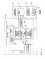
- FIG. 1is a block diagram illustrating a keyboard system according to one exemplary embodiment of the disclosed systems and methods.
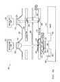
- FIG. 2Ais a diagram for a structure having both a haptics-enabled analog key and a digital key according to one exemplary embodiment of the disclosed systems and methods.
- FIG. 2Billustrates a haptics transducer assembly according to one exemplary embodiment of the disclosed systems and methods.
- FIG. 2Cillustrates a haptics transducer configuration according to one exemplary embodiment of the disclosed systems and methods.
- FIG. 2Dis a diagram for a structure having both an analog key and a digital key according to one exemplary embodiment of the disclosed systems and methods.
- FIG. 2Eis a diagram for a structure having a haptics-enabled analog key according to one exemplary embodiment of the disclosed systems and methods.
- FIG. 2Fillustrates a haptics-enabled keycap assembly according to one exemplary embodiment of the disclosed systems and methods.
- FIG. 2Gillustrates a haptics-enabled keycap assembly according to one exemplary embodiment of the disclosed systems and methods.
- FIG. 2Hillustrates a haptics-enabled keycap assembly according to one exemplary embodiment of the disclosed systems and methods.
- FIG. 2Iillustrates a haptics-enabled keycap assembly according to one exemplary embodiment of the disclosed systems and methods.
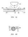
- FIG. 3Ais a diagram for different depressed states for a half-dome structure according to one exemplary embodiment of the disclosed systems and methods.
- FIG. 3Bis a diagram for a top view of the capacitive contacts for the half-dome structure according to one exemplary embodiment of the disclosed systems and methods.
- FIG. 4Ais a block diagram illustrating a keyboard system according to one exemplary embodiment of the disclosed systems and methods.
- FIG. 4Billustrates haptics control circuitry and other associated circuitry according to one exemplary embodiment of the disclosed systems and methods.
- FIG. 4Cillustrates haptics control circuitry and other associated circuitry according to one exemplary embodiment of the disclosed systems and methods.
- FIG. 4Dillustrates haptics control circuitry and other associated circuitry according to one exemplary embodiment of the disclosed systems and methods.
- FIG. 5illustrates methodology for initialization of pressure-sensing digital output circuitry according to one exemplary embodiment of the disclosed systems and methods.
- FIG. 6illustrates methodology for initialization of haptics control circuitry, sensing pressure applied to keys, producing a toggled digital signal representative thereof, and inducing haptics motion in a pressed key according to one exemplary embodiment of the disclosed systems and methods.
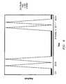
- FIG. 7illustrates a haptics vibration waveform according to one exemplary embodiment of the disclosed systems and methods.
- FIG. 8illustrates a haptics vibration waveform according to one exemplary embodiment of the disclosed systems and methods.
- FIG. 9illustrates a haptics vibration waveform according to one exemplary embodiment of the disclosed systems and methods.
- FIG. 10illustrates a haptics vibration waveform according to one exemplary embodiment of the disclosed systems and methods.
- an information handling systemmay include any instrumentality or aggregate of instrumentalities operable to compute, classify, process, transmit, receive, retrieve, originate, switch, store, display, manifest, detect, record, reproduce, handle, or utilize any form of information, intelligence, or data for business, scientific, control, or other purposes.
- an information handling systemmay be a personal computer, a server computer system, a network storage device, or any other suitable device and may vary in size, shape, performance, functionality, and price.
- the information handling systemmay include random access memory (RAM), one or more processing resources such as a central processing unit (CPU) or hardware or software control logic, ROM, and/or other types of nonvolatile memory.
- Additional components of the information handling systemmay include one or more disk drives, one or more network ports for communicating with external devices as well as various input and output (I/O) devices, such as a keyboard, a mouse, and a video display.
- the information handling systemmay also include one or more buses operable to transmit communications between the various hardware components.
- systems and methodsare provided to implement haptics for one or more individual keys of an information handling system keyboard (e.g., such as a variable pressure sensitive keyboard) using haptics actuation circuitry (e.g., such as piezo transducer circuitry) that is controlled by haptics control circuitry.
- haptics actuation circuitrye.g., such as piezo transducer circuitry
- the solutions described hereinmay be employed to enable haptics for keyboard keys including those keys used in variable pressure sensitive keyboards such as described in U.S. patent application Ser. No. 12/316,703 filed Dec. 16, 2008, and U.S. patent application Ser. No. 12/802,468 filed Jun. 8, 2010, each of which is incorporated herein by reference in its entirety for all purposes.
- Such variable pressure sensitive keyboardsmay be employed, for example, in gaming applications and information handling systems that are specifically designed for gaming applications.
- the disclosed systems and methodsare useful for any other keyboard applications in which variable pressure sensitive keys may be employed.
- hapticsmay be provided for pressure sensitive keys that produce a digital open/short signal that is representative of the amount of pressure applied to a given key at a given time.
- Conventional keyboardstypically use rubber dome based keys that provide a momentary-on switch contact via a make-or-break contact with two layers of flex PCB (printed circuit board) with a raw exposed conductor pad on both layers that come into contact with one another upon a key press.
- W, A, S, and D keysfor travel movements (forward, left, backward, right respectively); Q and E keys are typically used for strafing left and right respectively; and the spacebar key is used for jumping, although gaming keys are not restricted to these particular keys or functions.
- hapticsto be employed in one embodiment with variable capacitance measurement for implementing pressure sensitive keys, and may be optionally implemented with user configurable granularity scales for these pressure sensitive keys to allow enhanced user control of how keys respond in a gaming application and/or any other desired application.
- user configuration informationsuch as user configurable granularity scales, may be found in U.S. patent application Ser. No. 12/316,703 filed Dec. 16, 2008, which is incorporated herein by reference in its entirety.
- variable pressure controlThere are many kinds of game genres.
- the features and ways to utilize variable pressure controlvary from game to game or from genre to genre.
- a particular variable pressure buttonmay be used to control the speed of fire (single shot, multiple shots, faster multiple shots, machine gun rapid fire).
- the variable finger pressure sensitivity of the keymay mean something completely different.
- game genresand even within a particular genre, there are many game titles, where the user will want to save their keyboard's pressure sensitive button definitions and/or haptics waveform motion characteristics in a profile for the game, even with the ability to categorize by game genre.
- the usermay want the full range of gradual variable control.
- the usermay want this button to act like a momentary on/off switch button.
- the usermay want the button to operate as four (4) possible positions (e.g., slow walk, fast walk, jog, sprint) depending on the amount of pressure applied by the finger.
- This user configuration information, and this user configurable granularity control in particular, as described below,can be communicated to and stored by the keyboard to provide the user this capability of configuring how the keyboard pressure sensitive keys and/or haptics waveform motion for individual keys will operate.
- the keyboard embodiments described hereinmay have from one to all of their keys controlled via pressure-sensitive sensors (e.g., such as variable impedance or variable capacitance sensors), and/or may be provided with corresponding haptics control circuitry and haptics actuation circuitry for one or more of the individual variable pressure sensitive keys of the keyboard.
- pressure-sensitive sensorse.g., such as variable impedance or variable capacitance sensors
- haptics control circuitry and haptics actuation circuitryfor one or more of the individual variable pressure sensitive keys of the keyboard.
- an injection molded rubber dome sheet and flex circuitrycan be used, in one exemplary embodiment, to accommodate both pressure sensitive keys and traditional momentary-on switch based keys, and any one or more of which keys may also include haptics actuation circuitry.
- a typical 24-bit digital pathwaycan be used from the keyboard array to the keyboard's microcontroller for any momentary-on keys.
- a keyboard microcontrollerhas three dedicated 8-bit digital input ports to take in this data, though it need not be limited to this.
- Current keyboardsuse rubber-dome momentary-on switches.
- the keycaphas a rod or “chimney stack” on its bottom side. There is also a nipple or actuator on the bottom side of the rubber dome. As the user presses down on the keycap, the chimney stack presses down on the rubber dome, which in turn presses the nipple/actuator down on the flex circuitry beneath it.
- pressure sensitive keysmay be configured to use rubber dome keys with conductive half-spheres or half-domes located on the underside of the rubber domes.
- the following principlemay be employed: as the conductive sphere is pressed harder against a printed circuit board (PCB) or flexible PCB underneath it, the conductive sphere's surface area contact increases with pressure, thus increasing the capacitance of that contact in relationship with a nearby charged trace.
- the capacitancecan be measured and sent to a keyboard controller as alternating open/short (alternating off/on) digital signals representative of the measured capacitance value without the need for further analog to digital signal conversion.
- the embodiments disclosed hereintherefore, can use analog-based variable-pressure keys and incorporate them with digitally-based momentary-on switches of typical keyboards to make a keyboard that supports both regular make/break keys and keys with variable finger pressure sensitivity, and at the same time that is compatible with legacy “momentary-on” measurement keyboard controllers such as are typically found in information handling systems such as notebook and desktop computers.
- This variable finger pressure sensitivityis particularly useful for gaming applications where there is a consistent need for more intuitive gaming interfaces.
- signal inputs from both types of keyscan be provided in one embodiment to a keyboard controller via a digital input block.
- digital inputcan be provided directly to the keyboard controller by the typical keyboard array of momentary-on switches. These are the keys that operate as either switch on or off, essentially providing a digital 1 or 0 back to the microcontroller.
- Capacitive-sensing or other key pressure-sensing circuitrycan also be present for providing alternating open/short digital input signals for the keyboard controller that are representative of the amount of pressure applied to a given pressure sensitive key at any given time.
- the keyboard controllercan also support any number of digitally based momentary-on switch based keys.
- the capacitive-sensing or other key pressure-sensing circuitrymay also provide key pressure indication signals (e.g., as a digital output signals or other suitable signal type) to haptics control circuitry that are representative of the amount of pressure applied to a given pressure sensitive key.
- the haptics control circuitrymay be configured to in turn produce a haptics control signal that corresponds to the pressure level (i.e., amount of force) applied to the given pressure sensitive key (e.g., as a vibration waveform having a vibration intensity corresponding to the pressure level).
- the haptics control circuitrymay provide the haptics control signal to haptics actuation circuitry that will be described further herein.
- pressure sensing measurement circuitrye.g., such as capacitive-sensing digital output circuitry
- haptics control circuitrymay be, for example, embedded or integrated within a keyboard controller, though it may also be located external to the microcontroller as well.
- a “drop-in” keyboardhaving both conventional momentary-on and pressure sensitive keys, as well as haptics control circuitry and associated haptics actuation circuitry (e.g., including piezo transducers) for one or more of the keys, may be provided that has digital outputs for both momentary-on and pressure sensitive types of keys that are compatible with a legacy digital keyboard controller.
- This capabilitymay be advantageously employed, for example, to enable a build-to-order methodology in which either type of keyboard (i.e., traditional keyboard with only momentary-on keys or gaming keyboard with at least some pressure sensitive and haptics-enabled keys) may be selectively assembled to a common information handling system notebook chassis or common desktop keyboard chassis having a legacy keyboard controller, e.g., based on details of a specific customer order.
- type of keyboardi.e., traditional keyboard with only momentary-on keys or gaming keyboard with at least some pressure sensitive and haptics-enabled keys
- the pressure sensitive keysmay be variable capacitance pads that are coupled to provide an analog signal input to capacitive-sensing digital output circuitry available from Texas Instruments of Dallas Tex. and having part number MSP430F2111.
- capacitive-sensing digital output circuitryavailable from Texas Instruments of Dallas Tex. and having part number MSP430F2111.
- any other type of suitable capacitive-sensing digital output circuitrymay be employed including, for example, any circuitry that uses RC discharge time to measure sensor capacitance as described in U.S. Pat. No. 3,936,674, which is incorporated herein by reference in its entirety.
- the capacitive-sensing digital output circuitrymay be further optionally provided (integrally or separately) with signal switching circuitry, e.g., switch circuitry configured to interface with the legacy keyboard matrix array (e.g., 16 columns ⁇ 8 rows) which require current sinking capability as well as to provide for capability of providing pressure sensitivity to all keys in a keyboard.
- signal switching circuitrye.g., switch circuitry configured to interface with the legacy keyboard matrix array (e.g., 16 columns ⁇ 8 rows) which require current sinking capability as well as to provide for capability of providing pressure sensitivity to all keys in a keyboard.
- the momentary-on switch based keys inputcan be sent via, for example, a 24-bit digital path to the digital I/O of the keyboard controller, e.g., legacy 8051-based microcontroller available from sources such as Intel, Infineon Technologies, NXP, Silicon Laboratories, etc.
- the keyboard controllercan also have an optional embedded I2C master/slave block used to talk to peripheral ICs (integrated circuits) for additional functionality.
- a serial EEPROMcan also be optionally provided as part of the keyboard to communicate with the keyboard controller, for example, to provide the VID (vendor identification) and DID (device identification) information to the microcontroller via the I2C bus.
- a combination pulse width modulator (PWM) and LED (light emitting diode) driver integrated circuitcan be used, such as part number MAX6964AEG available from Maxim.
- PWMpulse width modulator
- LEDlight emitting diode
- Such integrated circuitscan receive commands from a host system, such as a personal computer, through the keyboard controller to drive RGB (red, green, blue) LEDs for keyboard lighting as instructed by the host system.
- the personal computer or host systemcan be configured to communicate with the keyboard controller through a USB connection, and the keyboard controller can be configured to convert these commands into a serial I2C stream provided to the PWM and LED driver integrated circuit which can in turn pulse width modulate the correct amount of light dimming and color to be provided for the keyboard lighting.
- the haptics control circuitrymay be, for example, a MAX11835 Rev. 2 chip (available from Maxim Integrated Products, Inc. of Sunnyvale, Calif.) that is capable of storing up to 16 different vibration waveforms, and which may be coupled to receive key pressure indication signals (e.g., as high/low digital signals) from the pressure-sensing digital output circuitry (e.g., TI MSP430F2111 controller).
- the haptics control circuitrymay in turn provide haptics control signals (e.g., in the form of selected vibration waveforms having a vibration intensity corresponding to the pressed key pressure level) to haptics actuation circuitry of the pressed key.
- the haptics actuation circuitry provided for each keymay be, for example, a piezo transducer such as KBS-20DA-3AN available from Kyocera Corporation of Kyoto, Japan, or may be another type of piezo transducer (e.g., available from sources such as CUI Inc. of Tualatin, Oregon or Murata Manufacturing Company Ltd. of Kyoto, Japan).
- a common injection-molded silicon rubber sheetcan be used with built in rubber domes and a common flex circuitry to support both digital momentary-on switches and pressure sensitive sensors (e.g., variable resistance or variable capacitance).
- pressure sensitive sensorse.g., variable resistance or variable capacitance
- the plastic keycapit can be configured to press on the depressible rubber dome which has a conductive spherical shaped actuator on the bottom side.
- the conductive spherical shaped actuatorcomes into contact with one plate of a capacitor.
- An insulating layeris located above a second plate for the capacitor so that it is isolated from the first plate.
- the conductive actuatordoes not contact the second plate, and a capacitance develops between the two plates.
- a capacitancedevelops between the two plates.
- Haptics actuation circuitrymay be provided for one or more keys of a variable pressure sensitive keyboard using any suitable methodology.
- a piezo transducermay be mounted to the bottom keyboard housing in position beneath the bottom second capacitor plate of a variable capacitive sensing keyboard such as of the type described above.
- a piezo transducermay be molded into a keycap or mounted on the underside of the keycap, e.g., in a manner that does not interfere with transmittal of light for backlighting the individual keys.
- the amount of finger pressure applied by a user to a given keyis sensed by the pressure sensing (e.g., variable capacitance sensing) digital output circuitry and is digitally provided to the keyboard controller via switching circuitry (e.g., optoisolator, MOSFET, etc.) that provides alternating open/short signal current pull down signals to the keyboard controller in a manner that emulates toggling of a conventional momentary off/on digital key.
- the pressure sensinge.g., variable capacitance sensing
- switching circuitrye.g., optoisolator, MOSFET, etc.
- the pressure sensing digital output circuitrymay also simultaneously provide a digital signal (e.g., high/low digital signal) representative of user-applied finger pressure to the haptics control circuitry, which in turn provides a haptics control signal representing a haptics motion (e.g., vibration) intensity corresponding to the amount of user pressure applied to the pressed key.
- a digital signale.g., high/low digital signal
- a haptics control signalrepresenting a haptics motion (e.g., vibration) intensity corresponding to the amount of user pressure applied to the pressed key.
- configuration information provided by a usermay be employed to adjust the operation of the pressure sensitive keys, e.g., via the pressure-sensing circuitry, other processing device, or software executing on a host system to which the keyboard is coupled.
- This user configuration informationcan optionally adjust the sensitivity and output levels generated by the Pressure Sensing Interface Circuitry based upon the pressure sensitive signals received with respect to the pressure sensitive keys as described in U.S. patent application Ser. No. 12/316,703 filed Dec. 16, 2008, which is incorporated herein by reference in its entirety.
- the keyboard controllercan then in turn provide output signals to the host system that indicate pressure amounts.
- the host computercan then use these keyboard output signals with respect to particular software application functions being operated by the host computer.
- such pressure sensitive functionsmay include the variability in the speed of travel (slow walk, trot, run, etc.), the amount of turning (slow, fast, etc.), the amount of strafing for a first-person-shoot game, the amount of braking for a vehicle race game, the degree of the rate of fire, the height of one's jump, and/or any other desired variable gaming feature.
- FIG. 1is a block diagram for a keyboard system 100 including pressure sensitive and haptics-enabled analog keys 104 together with digital keys 106 .
- a keyboard systemmay be provided only with haptics-enabled analog keys, with both haptics-enabled analog keys and haptics-enabled digital keys, or only with haptics-enabled digital keys.
- a keyboard controller 110is coupled through pressure sensing interface circuitry 185 to analog keys 104 of a key area 102 that is part of a keyboard device body.
- the key area 102includes both analog keys 104 and digital keys 106 (e.g., in one embodiment key area 102 may include a QWERTY keyboard), although any other style of multi-key key area may be employed.
- the digital keys 106represent keys that are momentary on keys that are detected as either depressed or not depressed. When a digital key is depressed, an output signal is sent to an I/O interface in the form of digital input block 112 within the keyboard controller 110 .
- the analog keys 104represent keys that are detected as being depressed by a variable amount or with a variable amount of pressure and that are each enabled to produce haptics motion feedback to a user indicative of the amount of pressure currently being applied to the pressed key by the user.
- keys 104 and 106may each be implemented using separately acutatable independent mechanical key structure mechanisms with corresponding separate key output circuitry and/or haptics actuation circuitry, and not implemented using membrane key output and/or membrane haptics elements of a multi-key-membrane style keyboard, although in other embodiments multi-membrane-style keys may alternatively by employed.
- pressure sensing interface circuitry 185When an analog key 104 is depressed, an indication of the force or extent to which it is depressed is provided to pressure sensing interface circuitry 185 that in the illustrated embodiment includes pressure-sensing digital output circuitry 190 and switching circuitry 192 . Pressure sensing interface circuitry 185 in turn provides a key pressure indication signal 145 that indicates the force or extent to which the key 104 is depressed to haptics control circuitry 160 which is coupled to actuate haptics motion to the pressed analog key by a haptics control signal 147 . Also illustrated in FIG. 1 is optional haptics controller 162 that may be present in haptics control circuitry 160 in some embodiments, and which is further described herein.
- Pressure sensing interface circuitry 185 and/or haptics control circuitry 160may each be provided in one exemplary embodiment as part of the keyboard device body. However, digital input block 112 and one or more components of pressure sensing interface circuitry 185 and/or haptics control circuitry 160 may alternatively be integrated within a microcontroller that is operating as the keyboard controller 110 and/or as part of the host system to which the keyboard is connected, if desired. The digital input block 112 and one or more of the components of pressure sensing interface circuitry 185 and/or haptics control circuitry 160 could also be implemented with external circuitry, as well.
- the pressure-sensing digital output circuitry 190includes a pressure sensing block 198 that receives an analog signal representative of the pressure applied to each of analog keys 104 and then outputs an alternating key pressure indication signal in the form of a high and low (high/low) digital output bit stream signal 133 having a frequency that is representative of this pressure being applied to each of analog keys 104 to a corresponding switching element of switching circuitry 192 (e.g., optoisolator, transistor such as MOSFETs, etc.).
- switching circuitry 192e.g., optoisolator, transistor such as MOSFETs, etc.
- Each switching element of switching circuitry 192responds to a digital signal 133 corresponding to a given analog key 104 by providing a toggled key pressure indication signal in the form of alternating open/short (off/on) digital signal 135 to a corresponding intersection point in the 16 ⁇ 8 key matrix which corresponds to that analog key 104 in a manner as described further herein.
- Pressure sensing block 198also outputs an alternating high and low (high/low) digital output bit stream signal 145 as a key pressure indication signal carrying a bit stream that is representative of this pressure being applied to the analog key 104 to haptics control circuitry 160 .
- any type of signale.g., signals 133 , 135 and 145
- any type of signalthat is representative of pressure applied to a given key may be characterized as a key pressure indication signal.
- pressure sensing interface circuitry 185may be implemented using any one or more circuitry components suitable for receiving analog signals representative of key pressure from pressure sensitive keys 104 and providing corresponding alternating open/short digital output signals having a toggled frequency that is representative of key pressure from pressure sensitive keys 104 that is suitable, for example, for digital input to a legacy keyboard controller 110 , and for also providing a signal representative of key pressure from pressure sensitive keys 104 to haptics control circuitry 160 .
- haptics control circuitry 160may be implemented using any one or more circuitry components suitable for receiving signals 145 representative of key pressure from pressure sensing interface circuitry 185 and for providing a haptics control signal 147 to cause haptics actuation circuitry of analog keys 104 to produce a variable haptics motion characteristic corresponding to the pressure level applied to the given pressure sensitive key (e.g., as a vibration waveform having a particular vibration intensity and/or frequency that corresponds to the currently applied real time key pressure level).
- one or more pressure sensitive keysmay be haptics-enabled using haptics actuation circuitry that is configured to impart haptics motion to the respective one or more pressure sensitive keys based on key pressure indication signals received from any suitable circuitry configuration, e.g., received from either haptics control circuitry 160 , or alternatively received directly from pressure-sensing digital output circuitry 190 (e.g., as signals 133 , 145 and/or 135 ) without requiring the presence of haptics control circuitry 160 .
- any suitable circuitry configuratione.g., received from either haptics control circuitry 160 , or alternatively received directly from pressure-sensing digital output circuitry 190 (e.g., as signals 133 , 145 and/or 135 ) without requiring the presence of haptics control circuitry 160 .
- the control circuitry 120 within the keyboard controller 110is coupled to receive on/off signals from the digital input block 112 .
- the control circuitry 120processes this key information and is connected to an output communication interface 118 so that this key information can be communicated to external devices, such as host components of an information handling system, through communication path 122 .
- external devicescan optionally communicate control and/or other configuration information to the keyboard controller through this same output communication interface 118 through communication path 122 . Examples of possible information handling system components may be found described in U.S. patent application Ser. No. 12/586,676, filed Sep. 25, 2009, which is incorporated herein by reference in its entirety.
- the output communication interface 118 and communication path 122can take a variety of forms.
- the communication path 122can be a wired communication path or a wireless communication path, as desired.
- the output communication interface 118will often be a Bluetooth interface if a wireless interface is desired and will often be a USB (universal serial bus) interface if a wired interface is desired.
- USBuniversal serial bus
- any desired communication interfacecan be utilized.
- the keyboard controller 110 and the control circuitry 120can be implemented as a microcontroller (e.g., legacy 8051-based microcontroller or custom microcontroller) that runs firmware stored on a memory device associated with the keyboard controller 110 and/or control circuitry 120 .
- the user configuration information 196can be optionally stored in random access memory (RAM) or other memory storage that is associated with pressure sensing circuitry 190 (either internally or externally).
- RAMrandom access memory
- the configurable analog key control parameters 196can be stored, for example, on a RAM device in the keyboard or on the host system (e.g., on a hard drive) and can provide a wide variety of configurable parameters that can be adjusted by a user through an application programming interface (API) to a software utility application that, for example, has a graphic user interface (GUI) to allow a user to edit the parameters through the software utility.
- APIapplication programming interface
- GUIgraphic user interface
- the user configuration informationmay be stored, for example, in nonvolatile or volatile memory on board the keyboard system 100 .
- the user configuration informationmay be stored on the host system or other device that is coupled by communication path 122 to output interface 118 off keyboard controller.
- the user configuration informationmay be stored on the host system or other device that is coupled by communication path 122 to output interface 118 off keyboard controller.
- single and/or multiple different user configuration files and/or multiple game (or application) configuration filesmay be stored allowing a user to select the applicable or desired keyboard configuration file depending on the game or application being used by the user and/or depending upon the particular user using the keyboard at the time in a manner as described in U.S. patent application Ser. No. 12/316,703 filed Dec. 16, 2008, which is incorporated herein by reference in its entirety.
- FIG. 2Ais a diagram for an exemplary embodiment 200 for a flexible-dome styled keyboard such as may be employed in USB full size keyboards.
- the key structuresinclude a haptics-enabled analog key and a digital key.
- depressing the analog keycap 202causes key output circuitry of a key structure that includes keycap 202 to produce a variable or analog output 220 to be provided by the keyboard
- depressing digital keycap 203causes a digital or on/off output 222 to be provided by the keyboard.
- the analog keysprovide a variable output
- the digital keysprovide a momentary-on output.
- the embodiment 200has a layered structural approach that overlays a base 212 .
- One or more of pressure sensitive analog keys 104may be implemented in this embodiment by a key structure that includes a separate (e.g., hard plastic) keycap 202 , a separate conductive and resilient and flexible half-dome structure 216 , and separate haptics actuation circuitry in the form of a piezo transducer 260 that is provided as separate (i.e., non-membrane style) circuitry from the haptics actuation circuitry of any other key structure of the keyboard.
- flexible half-dome structure 216may be a GRSP pill as manufactured by ARC USA, Inc.
- Such a GRSP materialis a non-silkscreen conductive ink which is manufactured in a half-dome “pill” form with a soft (rubberish-like) material and that may exhibit a good operation life (number of switching actuations).
- flexible half-dome structure 216may be a conductive pill made by ShinEtsu Polymer America, as used in their TouchDisc products.
- a pillmay be co-molded onto the same silicon rubber sheet with which rubber domes ( 213 and/or 215 ) are made from.
- base 212may be configured in this embodiment to contain the corresponding separate haptics actuation circuitry 260 of each separate key structure in a manner described further below.
- each haptics-enabled key structuremay be characterized as a separately acutatable independent mechanical key structure mechanism with corresponding separate key output circuitry and/or haptics actuation circuitry, i.e., that is not implemented using membrane key output elements of a multi-key-membrane style keyboard.
- haptics actuation circuitryi.e., that is not implemented using membrane key output elements of a multi-key-membrane style keyboard.
- multi-membrane-style keysmay alternatively by employed.
- base 212represents the bottom of the layered structure and can be made of a material that can support the key structure, such as a hard plastic material that may also serve as the bottom keyboard housing material.
- a flexible PCB (printed circuit board) 210is then provided on top of the base 212 .
- the PCB 210includes circuit traces or connections that provide for electrical signals to be generated and communicated when keys are depressed.
- circuit connection 236is used to provide digital output 222
- circuit connection pads 230 and 231are used to provide the analog output 220 .
- the next layeris flexible insulator 208 , such as a flexible PCB without circuit connections.
- the next layeris another flexible PCB 206 that can include circuit traces or connections that work in conjunction with the connections on PCB 210 to provide for electrical signals to be generated and communicated when keys are depressed.
- circuit connection 234is used to provide the digital output 222 .
- a relatively thin flexible layer 204can then be provided above PCB 206 and can be made from an injection molded silicon rubber sheet.
- This flexible layer 204is configured to have a molded flexible rubber dome for each key.
- flexible dome 215is provided for analog keycap 202
- flexible dome 213is provided for digital keycap 203 .
- flexible dome 216may be co-molded to the rubber dome sheet 204 .
- haptics actuation circuitry 260in the form of a piezo transducer may be mounted to (and optionally within) base 212 (e.g., which may be a bottom plastic keyboard housing material structure).
- piezo transducer 260includes a metal plate 273 (for signal +) and ceramic capped electrode 275 (for ground).
- An example of such a piezo transduceris KBS-20DA-3AN, available from Kyocera Corporation.
- piezo transducer 260may be mounted underneath the bottom-most layer 210 of flex circuitry, yet on the upper or top-side surface of base 212 of the keyboard.
- piezo transducer 260is mounted on a raised piezo support structure 266 that is protrudes upward within a cavity 264 of the base 212 , e.g., such that the raised support structure 266 is surrounded by a depression or “valley” area.
- raised piezo support structure 266is provided as a circular rib having a diameter that is less than the outer diameter of the metal plate 273 of piezo transducer 260 in a manner such that the outer diameter of the circular rib does not exceed the diameter of the inner circle (ceramic capped electrode 275 ) of piezo transducer 260 .
- the outer diameter structure of the piezo transducer 260e.g., metal plate 273 with a varying electrical input pulse applied to it
- flexe.g., contract/expand
- flape.g., flap up and down without restriction in order to produce a vibration haptics motion for the key.
- the haptics vibrationis up and down, e.g., in a direction parallel to the up and down key travel direction of key cap 202 that is illustrated in FIG. 2D .
- a raised piezo support structure 266may alternatively be provided in the form of a boss or combination of a boss and a rib. Further, as shown in FIG. 2B , optional support ribs 268 may be provided to ensure adequate support for the piezo transducer 260 , and to ensure that when the key is pressed that the flexible half-dome structure 216 presses against a flat bottom with adequate pressure distribution due to the ribs. This in turn may increase the reliability of piezo transducer 260 by making it less prone to mechanical damage due to inadequate mechanical support from underneath.
- Optional support ribs 268may be shaped in such a way so as to provide mechanical support under ceramic capped electrode 275 so that ceramic capped electrode 275 substantially does not mechanically flex when pressed upon by flexible half-dome structure 216 .
- the diameter of raised piezo support structure 266may be equal or greater than the diameter of flexible half-dome structure 216 when pressed with maximal force so as to ensure substantially no physical damage to piezo transducer 260 when pressed on by flexible half-dome structure 216 with a lot of force.
- the raised piezo support structure 266is shaped and dimensioned to provide sufficient mechanical support to the piezo transducer 260 to ensure no flexion when pressed upon by the overlying key structure, while at the same time providing a solid bottom or base for the rubber dome key to press against to “make” the electrical connection (i.e., to indicate a key press).
- Piezo transducer 260may be mounted to raised piezo support structure 266 using any suitable methodology e.g., adhesives such as epoxy or silicon, mechanical mounting such as by press molding, etc.
- piezo transducer 260may be mounted to raised piezo support structure 266 using a dampening mounting structure 262 (e.g., such as 1/32 inch thick 3M Double Coated Polyethylene Foam Tape model 4492W, having a conformable closed cell foam with a high strength acrylic adhesive that provides high adhesion strength to a wide variety of surface materials.
- a dampening mounting structure 262e.g., such as 1/32 inch thick 3M Double Coated Polyethylene Foam Tape model 4492W, having a conformable closed cell foam with a high strength acrylic adhesive that provides high adhesion strength to a wide variety of surface materials.
- a dampening mounting structure 262may be a 35-55 mil thick ⁇ 1 ⁇ 2 inch diameter double-sided adhesive rubberized “Glue Dot”, such as GlueDot model no. XD32-402, available from Glue Dots International, an Ellsworth Adhesives Company, Germantown, Wis. Such a Glue Dot may be manufactured to have a high tack strength adhesive for industrial applications. It will be understood that such Glue Dot double-sided adhesive products may be selected to have varying tack (strength) levels, varying thicknesses from 12 mils to 100 mils, and/or custom made to meet specific mechanical needs of a given application.
- a rubberized or dampening consistency of a mounting structuremay be selected in order to dampen transmittal of the vibration of the piezo transducer 260 through the piezo support structure 266 to the base 212 , while at the same time allowing transmittal of the piezo transducer vibration through layers 210 / 208 / 206 , flexible half-dome structure 216 and flexible dome 215 to the keycap 202 and the user's finger when the keycap 202 is pressed down by the user in the manner shown in FIG. 2D to cause downward key travel of key cap 202 relative to base 212 .
- dampening mounting structure 262may be varied to fine tune the degree of dampening required to obtain the desired degree of vibration in the key cap ( 202 and/or 203 ) while dampening any vibration from entering back into the keyboard housing via base 212 .
- the height of the circular rib 266is less than the height of the top surface 269 of base 212 by a distance “x” that is equivalent to the combined thickness of piezo transducer 260 and dampening mounting structure 262 such that the top surface 271 of piezo transducer 260 is coplanar (disposed in the same plane) or parallel to top surface 269 of base 212 when piezo transducer 260 and dampening mounting structure 262 are assembled to piezo support structure 266 as shown by dashed lines 281 in FIG. 2C .
- Such a configurationmay be employed to ensure that all keycaps 202 press downward against a surface which is disposed along a common plane for each keycap 202 .
- flex layer 210may be utilized to route piezo signals (+ and ⁇ ) via flex trace 279 to haptics actuation circuitry 260 .
- an actuator 214is also provided underneath the dome 213 that causes circuit trace 234 to be engaged with circuit trace 236 when the digital keycap 203 is depressed.
- circuit trace 234 touches the circuit trace 236a signal is now active indicating the key was pressed, causing a digital output 222 to be generated.
- This digital output 222can be configured to provide a momentary-on indication of whether or not the key has been depressed.
- the digital keycap 203can be made from hard plastic.
- the conductive and flexible half-dome 216is provided to flex when depressed, as described in more detail below, to vary the capacitance associated between circuit pad 231 and circuit pad 230 when analog keycap 202 is depressed.
- flexible half-domeflexes to contact circuit pad 231 through which haptics vibration motion is transmitted from piezo transducer 260 when keycap 202 is depressed.
- FIG. 2Dshows assembled keyboard embodiment 200 with keycap 202 so depressed. Notice that as pressure is applied to the key, flexible half-dome structure 216 not only comes into contact with circuit pad 231 , but its surface area on insulator layer 208 starts to increase due to the pressure.
- the half-dome 216 contact diameter of half-dome 216 on surface of insulator layer 208approaches that of the diameter of pad 230 .
- Flexible half-dome 216may be resilient so as to return the depressed keycap 202 to its unpressed condition when the keycap 202 is no longer depressed.
- Essentially pad 231 and pad 230are the two plates of a capacitor. The variable capacitance between these two plates are measured from signal trace 232 by sending this trace to capacitance reading circuitry. As stated below, pad 230 can be coupled to ground. It is noted that the conductive and flexible half-dome 216 can be made, for example, from a conductive rubber material, that is conductive, flexible and capable of reforming its shape after being depressed and released. Examples of suitable materials are discussed above. Further, prior art techniques have made this material from a carbon impregnated rubber.
- one or more keys of a keyboard assemblymay be provided with haptics circuitry in a variety of alternative ways with key output circuitry implemented between a keycap 202 and underlying haptics actuation circuitry 260 that is mounted to (and optionally within) base 212 in a manner described elsewhere herein.
- different types of keyboard assembliesmay be provide with haptics capability, including both desktop information handling system keyboards and keyboards for portable information handling systems, such as notebook computers.
- the mounting of a piezo transducer or other haptics actuation circuitry to the keyboard baseunder the flex layers or other key output circuitry as described in relation to FIGS.
- the haptics circuitryneeds to be mounted in such a way that intervening opaque materials (e.g., layers) don't obstruct the light produced under the key used for backlighting the key.
- FIG. 2Eillustrates an example of an alternative embodiment in which haptics actuation circuitry may be implemented between the key output circuitry and the keycap 702 .
- FIG. 2Eillustrates the mounting of piezo transducer type haptics circuitry to the underside of a backlighted keycap 702 of a keyboard such as employed for an Alienware model m11x, m15x and m17x notebook computers available from Dell Computer of Round Rock, Tex., although other types of keycaps may be employed.
- Such a low profile keyboardmay employ a collapsible dual lever action key mechanism that supports the keycap 702 by utilizing mating lever members 722 and 724 that are secured at one end through intervening layers 210 , 208 , 206 and 704 to a metal base 712 of an analog pressure sensitive keyboard assembly 700 at a hinge point 710 and to a slidable stopper 711 at the other end.
- the mating lever members 722 and 724are configured to pivot downward relative to each other with a scissor-like action when the keycap 702 is depressed, and are provided with a resilient member that returns the keycap 702 upward to its unpressed position when the keycap 702 is no longer pressed.
- An example of such a collapsible key mechanismmay be found in Flextronics model no. DELH-B2625040G00001 keyboard (e.g. as found in the Alienware m15x) and manufactured by Darfon of Gueishan, Taoyuan 333, Taiwan, R.O.C.
- a single layer disc type piezo transducer 260is mounted on the underside of keycap 702 such that the larger diameter metal plate 273 of the transducer is mounted against the keycap within a complementarily-dimensioned recessed area 703 (e.g., adhered to and/or mechanically mounted by sliding into grooves 950 provided in the sides of recess 703 as shown by the arrows in FIGS. 2H and 2I ), and with the smaller diameter ceramic electrode portion 275 of the transducer facing downward toward a transparent or translucent flexible rubber dome structure 705 which extends through an opening 707 provided in a top flex circuit layer 704 .
- a conductive and flexible half-dome structure 216is provided to flex when depressed as previously described to vary the capacitance associated between circuit pad 231 and circuit pad 230 when analog keycap 702 is depressed.
- a two-wire flex circuit 279may be provided as shown to electrically connect the piezo transducer 260 (e.g., Kyocera Corporation, Model No. KBS-20DA-3AN piezo transducer) to the top flex circuit layer 704 .
- Top flex circuit layer 704is typically printed with black ink and used in non-haptics enabled keyboard assemblies only for purposes of blocking light from an underneath backlight element 750 (e.g., RGB LED, single color LED, etc.) from bleeding through at locations between openings between backlit keys.
- the backlight element 750shines thru the side of a polycarbonate sheet 751 which acts as a backlight-light spreader, to spread the backlight under many keys.
- this existing layer 704 of flex circuitmay be used to route signals between the haptics circuitry (e.g., piezo transducer 260 ) and haptics control circuitry which is described further herein.
- haptics circuitrye.g., piezo transducer 260
- haptics control circuitrywhich is described further herein.
- piezo transducer 260 or other type of haptics circuitrymay be mounted into a recessed area 703 that is molded into the bottom side of a keycap 702 .
- This particular configurationallows for easier assembly in manufacturing, provides protection to the piezo transducer from flexion, and helps improve the reliability of the rubber dome 705 by preventing it from getting accidentally punctured from any sharp edges on the piezo (e.g., such as by solder connection to the wires 279 or flex circuitry 704 ).
- haptics circuitrymay be mounted to the bottom side of a keycap 702 using any other suitable methodology, e.g., using double sided adhesive foam tape or an adhesive “Glue Dot” such as described in relation to FIGS. 2A-2D .
- flex cable 279may be routed from the side of the key where the dual-lever scissor action key switch pivots from connection between levers 722 and 724 to help avoid flex cable 279 from getting accidentally pinched by the action of dual levers 722 and 724 when keycap 702 is pressed by a user.
- an opening complementary to the outer dimensions of rubber dome 705may be formed in both levers 722 and 724 through which rubber dome 705 upwardly extends such that the top surface of the rubber dome 705 rests upon the bottom surface of ceramic electrode 275 of piezo transducer 260 .
- a light pipemay be optionally added to keycap 702 to transfer backlight light as it shines through flex circuitry 704 where there's no blank ink acting as an aperture control.
- FIGS. 2F and 2Gillustrate alternative embodiments of multi-part haptics-enabled keycap assemblies that may be employed for “chimney stack” style key applications such as used for USB or desktop computer type keyboards.
- Such keyboardsmay employ chimney stacks that may be provided, for example, as circular or square cross-sectional plastic rods connected to the keycap that press down onto a rubber dome to which provide a spring-like action to return the key back up to position when no finger is pressed on it.
- two-piece keycapsthat may be provided in one embodiment in the form of a keycap that's molded or adhered onto a chimney stack once the piezo is mounted inside of it such that the piezo is very close to the finger (under key cap) to strengthen the vibration haptics effect felt by the user while at the same time weakening the haptics vibrations transferred to the keyboard housing or base 212 .
- a piezo transducer 260 or other haptics circuitrymay be molded as part of a multi-piece keycap structure that is assembled together at the factory. As shown, piezo transducer 260 is mounted within a recessed area 803 of keycap 802 that is then molded to chimney stack 804 which is in turn received within a complementary aperture of key guide 806 . Piezo transducer 260 is thus configured in a position in which it is allowed to flex (or vibrate) underneath the keycap lid 802 once keycap 802 is applied and sealed to the chimney stack 804 with piezo transducer 260 positioned therebetween.
- flex circuit 279connects piezo transducer 260 to underlying piezo control circuitry through access opening 811 that is defined in a surface of the keyboard assembly through which key guide 806 with chimney stack 804 key guide downwardly extends to key activation circuitry that senses when each keycap 802 is depressed downward with its respective chimney stack 804 .
- each chimney stack 804“spring loaded”, via a rubber dome located inside circular opening 806 whereby cylindrical shaped chimney stack 804 presses against the top surface of the rubber dome, to return to a raised position when downward user key pressure is removed.
- a piezo transducer 260may be mounted within a recessed area 903 of a chimney stack 904 that is then molded to keycap 902 with piezo transducer 260 positioned therebetween. Chimney stack 904 is in turn received as shown within a complementary aperture of key guide 906 . Piezo transducer 260 is thus configured in a position in which it is allowed to flex (or vibrate) underneath the keycap lid 902 once keycap 902 is applied and sealed to the chimney stack 904 with piezo transducer 260 positioned therebetween. As with the embodiment of FIG.
- flex circuit 279connects piezo transducer 260 to underlying piezo control circuitry through access opening 811 that is defined in a surface of the keyboard assembly through which key guide 906 with chimney stack 904 key guide downwardly extends to key activation circuitry that senses when each keycap 902 is depressed downward with its respective chimney stack 904 .
- each chimney stack 904is “spring loaded”, via a rubber dome located inside square shaped opening 906 whereby rectangular shaped chimney stack 904 presses against the top surface of the rubber dome, to return to a raised position when downward user key pressure is removed.
- plate two 230may be connected to ground, and plate one 231 may have a trace connected to it that is routed to an I/O pin on pressure-sensing digital output circuitry 190 (e.g., TI MSP430 controller).
- the conductive material for the capacitive actuatormay either be impregnated into the rubber dome material, or may be an external piece of material that is attached to the rubber dome via co-molding, mechanical/snap-in means, via adhesive, or a hot fusing method. Other methods for providing a conductive and flexible actuator can also be used.
- electrical pad 230is shaped like a donut with an insulative material in the middle.
- Circuit trace 232connects to the circuit pad 231 through a via within the insulative material with the conductive pad 231 being located in the middle of the insulative center of the donut area.
- Pad 230may be attached to a signal trace, but the preferred method of embodiment has pad 230 being coupled to a given charge, such as being attached to ground. Due to insulator layer 208 , the conductive half-dome 216 may only make contact to circuit pad 231 through the hole in the insulator 208 .
- the conductive and flexible half-dome 216makes contact with circuit pad 231 and is deformed by pressure from the analog keycap 202 , the capacitance between pad 231 and pad 230 increases. As more pressure is applied to the analog keycap 202 , the half-dome 216 gradually deforms and flattens-out on top of the insulator, causing a larger conductive surface area to run parallel to pad 230 . Effectively, there are two parallel plates provided by pads 231 and 230 with a fixed thickness insulator/dielectric between them. Pad 230 has a fixed surface area as it is printed onto the PCB 210 .
- pad 231has a variable surface area or is a variable sized parallel plate due to the action of half-dome 216 as it is depressed. As the surface area of pad 231 gradually increases due to action of half-dome 216 as greater force is applied to the analog keycap 202 , the capacitance between plates 231 and 230 gradually increases as well. This variable capacitance can be sensed, measured and used as an indication of the pressure being applied to the analog keycap 202 . When implemented using variable capacitance methodology, the sensor may be implemented on the PCB directly.
- haptics enabled keysmay be implemented with other types of pressure sensitive keys (e.g., via the use of force sensitive resistors or the conductive flexible half-dome material—both of which employ materials that change their electrical impedance with applied pressure) using haptics circuitry and/or haptics control circuitry described herein.
- conventional digital keysmay be provided with haptics capability using systems, apparatus and/or methods described herein.
- FIG. 3Ais a diagram for different depressed states for the conductive and flexible half-dome structure 216 of FIG. 2A .
- the bottom edge of the half-dome structure 216has a bottom edge position indicated by Line 1 .
- Line 2represents the bottom edge of half-dome structure 216 when it has been depressed some distance.
- Line 3represents the bottom edge of half-dome structure 216 when it has been depressed far enough to touch connection pad 231 through the gap in insulator 208 . It is also noted that bottom edge will have flattened out slightly due to this contact, as shown with respect to Line 3 .
- Line 4shows that the bottom edge of half-dome structure 216 will continue to flatten as it is depressed.
- Line 5is a further indication of this flattening of the half-dome structure 216 . As stated above, as the half-dome structure 216 is moved closer to connection pad 231 , half-dome structure 216 will touch connection pad 231 and will then flatten out causing a larger surface area for electrical plate 231 relative to electrical plate 230 .
- connection pad 231can be coupled to pressure sensing block 198 (of pressure-sensing digital output circuitry 190 ) that operates to sense and measure the electrical information provided from connection pad 231 .
- FIG. 3Bis a diagram for a top view of the capacitive contact pads 230 and 231 for the half-dome structure.
- an insulative material 308sits between the contact pad 230 and the contact pad 231 .
- the contact pad 230can be coupled to ground.
- the variable capacitance (Cx) between the pads 230 and 231 caused by the motion of the half-dome structure 216can be used to provide the analog output 220 .
- C fixeda fixed capacitance component associated with the position of the pads 230 and 231
- C variablevarying capacitance component
- the change in capacitance ( ⁇ C) caused by varying capacitance component (C variable ) due to the half-dome 216can be then used as an indicator of the pressure that has been used to depress the key associated with the half-dome structure 216 .
- FIG. 4Aillustrates one exemplary embodiment of a keyboard system 100 in which analog keys 104 are haptics-enabled pressure sensitive capacitive keys (such as described in relation to FIGS. 2A-2I , 3 A and 3 B), having capacitive pads 231 a - 231 g that are coupled to pressure-sensing digital output circuitry 190 .
- analog keys 104are haptics-enabled pressure sensitive capacitive keys (such as described in relation to FIGS. 2A-2I , 3 A and 3 B), having capacitive pads 231 a - 231 g that are coupled to pressure-sensing digital output circuitry 190 .
- One exemplary embodimentmay implements the pressure-sensing digital output circuitry 190 as a Texas Instruments 16-bit ultra-low power capacitive sensing microcontroller part number MSP430F2111, however other microcontrollers may be used.
- pressure-sensing digital output circuitry 190is specifically coupled for sensing and measuring capacitance for each key via a corresponding general purpose input output (GPIO) port P 1 . 0 to P 1 . 6 that incorporates a falling edge triggered digital interrupt.
- GPIOgeneral purpose input output
- pressure-sensing digital output circuitry 190is specifically coupled for sensing and measuring capacitance for each key via a corresponding general purpose input output (GPIO) port P 1 . 0 to P 1 . 6 that incorporates a falling edge triggered digital interrupt.
- GPIOgeneral purpose input output
- pressure-sensing digital output circuitry 190employs RC capacitive measurement methodology with falling edge event driven interrupt performed on a per pin basis.
- Information on RC capacitive measurementmay be found, for example, in U.S. Pat. No. 3,936,674, which is incorporated herein by reference in its entirety.
- each capacitive pad 231 a through 231 gis charged and discharged via traces 131 one at a time, and the amount of time for the discharge of each corresponding pad 231 is measured using a timer operating at a high speed (e.g., timer operating at about 16 MHz or other suitable speed).
- pressure-sensing digital output circuitry 190may be implemented by a TI MSP430F2111 microcontroller or other suitable circuitry that employs RC discharge time to measure the variable capacitance of each analog key 104 as follows.
- each signal lines 131acts as a single input/output (I/O) line between a given falling-edge triggered interrupt digital port P 1 .X of pressure-sensing digital output circuitry 190 and a corresponding given analog key 104 .
- the capacitive plate of each analog key 104is also coupled to ground through a resistor 199 (e.g., 6 M ⁇ or other resistor value selected to provide sufficiently slow RC discharge time to provide the desired measurement resolution for the given application).
- each signal line 131is employed to charge, discharge and produce an interrupt when the voltage of the capacitor of analog key 104 crosses a low voltage threshold.
- a given port P 1 .X of a given I/O line 131may be set to output high to charge (e.g., with 500 nA charging current) the capacitive plate of a corresponding analog key 104 to near V CC , and a free-running timer of the pressure-sensing digital output circuitry 190 read to mark the start time.
- the given port P 1 .Xis set to input with negative-edge interrupt enabled and the resistor coupled to the capacitive plate of the corresponding analog key 104 discharges the capacitive plate of the analog key 104 to ground, during which pressure-sensing digital output circuitry 190 may go into low power mode to save power.
- V ILinterrupt voltage
- an interruptis generated which causes the free-running timer to be read again and the elapsed time for discharge of the capacitive plate of the analog key 104 from near V CC to V IL is calculated.
- Pressure-sensing digital output circuitry 190may then return to high power mode.
- the discharge timer count of the capacitive plate of each analog key 104is proportional to its present capacitance, which depends on the amount of pressure currently applied to the key 104 .
- multiple capacitor readings of a given analog key 104may be averaged to filter out common mode noise, e.g., by using a charge cycle followed immediately by a discharge cycle and averaging the two values.
- pressure-sensing digital output circuitry 190provides a corresponding digital output 133 for each capacitive pad 231 and its input 131 .
- Each digital output signal (P 2 . x ) 133corresponds to a respective capacitive pad input (P 1 . x ) 131 .
- each digital output signal 133is produced in an intermittent alternating high/low manner with a frequency that emulates the action of a user's finger toggling away at a conventional digital “momentary on” digital key at a variable speed that is based on the amount of pressure being applied to the corresponding pressure sensitive analog key 104 .
- open/short mechanical user toggling controlmay be advantageously replaced by electrical control based on the key pressure applied by a user to provide a similar intermittent alternating high/low signal output without requiring a user to toggle the keys.
- the exemplary microcontroller of pressure-sensing digital output circuitry 190 of FIG. 4Aemploys 8 digital falling-edge triggered interrupt inputs Port 1 (P 1 . x ), and 8 digital outputs Ports 2 (P 2 . x ), it is possible to select a different chip(s) to support more pressure sensitive keys.
- pressure-sensing digital output circuitry 190also provides a signal 145 corresponding to each capacitive pad 231 that indicates the force or extent to which the key 104 is depressed to haptics control circuitry 160 .
- each signal 145is a digital signal similar to the corresponding digital output signal 133 produced by pressure-sensing digital output circuitry 190 , i.e., being produced in an intermittent alternating high/low manner at a variable speed that is based on the amount of pressure being applied to the corresponding pressure sensitive analog key 104 .
- a pressure indication signal 145may be any other type of signal suitable for indicating pressure applied to a corresponding pressure sensitive analog key 104 .
- Haptics control circuitry 160in turn produces a corresponding haptics control signal 147 to actuate the haptics circuitry 260 that corresponds to (e.g., is mechanically coupled to or otherwise associated with) the particular pressed key 104 .
- haptics control signal 147may be operable to cause haptics circuitry 260 to produce a vibration or other type of movement for the pressed key 104 that is proportional or otherwise variable relative to the amount of pressure currently being applied to the corresponding pressed key 104 .
- haptics control circuitry 160may include at least one haptics controller 162 as shown. Although one haptics controller 162 receiving multiple pressure indication signals 145 and producing multiple corresponding haptics control signals 147 is illustrated in FIG. 4A , it will be understood that haptics control circuitry 160 may include more than one haptics controller, e.g., with one haptics controller 162 being provided for independently actuating haptics circuitry 260 of each separate pressure sensitive key 104 . In this regard, additional embodiments are illustrated further herein that show just a few of the different circuit configurations that are possible in the implementation of the disclosed systems and methods.
- keyboard system 100is implemented to be interchangeable with a legacy USB keyboard for interconnection with standard 8 bit keyboard controller 110 via a standard 16 ⁇ 8 key matrix 199 with 16 columns ⁇ 8 rows and native device drivers.
- standard 16 ⁇ 8 key matrix 199with 16 columns ⁇ 8 rows and native device drivers.
- one or more features of the disclosed systems and methodsmay be implemented in non-legacy or customized keyboard systems, and in any arrangement of one or more circuitry components as may be suitable for a given application.
- legacy keyboard controller 110has a standard keyboard matrix open/short input 199 provided for the 104 keys on a standard keyboard that is arranged as 16 columns by 8 rows, so that only 24 signals interface with the keyboard controller 110 , rather than a signal line per key which would require over 100 signals to the keyboard controller 110 .
- the keyboard controller 110operates by initially selecting a single row and applying a logic level 1 to it. There are 16 keys in a column, with only one of those keys intersecting with the particular row that's at logic 1. To detect if a key is pressed in a row, each column is sequentially grounded. If a key is pressed, it shorts the column to the row, thus causing the row voltage to drop or go low.
- the keyboard controller 110When the keyboard controller 110 detects the low voltage on the selected row, the pressed key can be determined by the column/row intersection that was electrically shorted. Once all columns have been queried in a single row, the keyboard controller 110 sequences to the next row, and so on until all rows have been queried, thus sampling the logic level for every key.
- switching circuitry 192may be provided as an interface between pressure-sensing digital circuitry 190 and legacy keyboard controller 110 for analog keys 104 . The purpose of the switching circuitry 192 is to convert a high/low digital output stream into a stream of opens/shorts. For example, as shown in FIG.
- a separate optoisolator 180has been provided for each corresponding analog key switch location.
- optoisolatorsinclude, but are not limited to, AVAGO 4N35 or ACPL-227 optocouplers available from Avago Technologies of San Jose, Calif.
- each optoisolator 180provides an electrical control over the make or break (short or open circuit) connection at a given column/row intersection location of keyboard matrix open/short input 198 for that particular key.
- the implementation of this embodiment of switching circuitry 192allows any key (and/or any number of keys) of a conventional keyboard matrix to be provided with pressure sensing capability.
- FIG. 4Billustrates one exemplary embodiment of haptics control circuitry 160 as it may be implemented with pressure sensing interface circuitry 185 , a keyboard controller 110 , and haptics actuation circuitry 260 provided in the form of a piezo transducer or other suitable haptics actuator.
- Haptics control circuitry 160may be implemented using any circuitry or combination of circuits suitable for controlling haptics actuation circuitry 260 based on the amount of pressure applied to an analog key 104 in a manner as described further herein.
- haptics control circuitry 160may include a haptics controller 162 (e.g., MAX11835 available from Maxim) and a flyback converter (transformer) circuit 420 as shown.
- haptics controller 162outputs a low voltage (e.g., 3 volt) waveform signal 146 representative of a selected vibration waveform that corresponds to the pressure applied to an analog key 104 .
- Optional flyback converter circuit 420may be present to amplify the low voltage waveform signal 146 (e.g., to about 160 volts sawtooth) and to provide this amplified signal 147 to the piezo transducer 260 of haptics actuation circuitry 260 .
- a low voltage waveform signal 146representative of a selected vibration waveform that corresponds to the pressure applied to an analog key 104 .
- Optional flyback converter circuit 420may be present to amplify the low voltage waveform signal 146 (e.g., to about 160 volts sawtooth) and to provide this amplified signal 147 to the piezo transducer 260 of haptics actuation circuitry 260 .
- haptics controller 162 and pressure-sensing digital output circuitry 190operate in parallel, and also interact with each other to enable variable pressure haptics for keys 104 using a two-path output signal architecture from pressure-sensing digital output circuitry 190 (i.e., a trigger/waveform address signal path 145 , and a toggle signal path 133 ).
- haptics controller 162may include or otherwise access memory 430 (e.g., RAM or any other suitable non-volatile or volatile memory) that stores one or more vibration waveforms.
- memory of a MAX11835 controllermay store up to 16 different vibration waveforms that are selected to correspond to different pressure force levels applied to a variable pressure sensitive key 104 .
- Each of the vibration waveformsmay be assigned a corresponding waveform address in memory of the controller.
- pressure-sensing digital output circuitry 190may output a pressure indication signal 145 as a falling edge trigger event to haptics controller 162 .
- the pressure indication signal 145may include the selected waveform address (e.g., 4 bit waveform address) that corresponds to the desired vibration waveform and current pressure level applied to a given key 104 .
- the haptics controllermay then retrieve the selected particular waveform from memory 430 according to the waveform address, and then output this selected waveform as low voltage waveform signal 146 to flyback circuit 420 .
- Duration of signal 146may be of any selected and suitable time, but in one embodiment may be a short duration waveform signal (e.g., of about 45 milliseconds) that loops or repeats over and over for a period corresponding to a polling period of pressure-sensing digital output circuitry 190 (e.g., for a period of about 1 ⁇ 2 second or other greater or lesser time value).
- a short duration waveform signale.g., of about 45 milliseconds
- a polling period of pressure-sensing digital output circuitry 190e.g., for a period of about 1 ⁇ 2 second or other greater or lesser time value
- PATH 2(toggle path) is implemented by the illustrated components as follows. After the 4 bit waveform of PATH 1 is loaded, key toggling is initiated by pressure-sensing digital output circuitry 190 by providing digital signal 133 to keyboard key matrix 199 and keyboard controller 110 via optoisolator 180 of output switching circuitry 192 in a manner as described elsewhere herein. The rate of the key toggling of digital signal 133 is dictated by the applied pressure level, and toggling occurs for a period corresponding to a polling period of pressure-sensing digital output circuitry 190 (e.g., for a period of about 1 ⁇ 2 second or other greater or lesser time value). In this regard PATHS 1 and 2 may operate in parallel, although PATH 1 may be started first due to the latency of loading in the waveform address via signal 145 .
- FIG. 4Cillustrates the embodiment of FIG. 4B in more detail, it being understood that in this exemplary embodiment separate haptics control circuitry 160 (with a separate haptics controller 162 and flyback circuit 420 ) may be provided to receive each corresponding pressure indication (haptics trigger output) signal 145 and to provide a respective haptics control signal to the corresponding haptics transducer 260 of each haptics enabled key 104 . As shown in FIG. 4C illustrates the embodiment of FIG. 4B in more detail, it being understood that in this exemplary embodiment separate haptics control circuitry 160 (with a separate haptics controller 162 and flyback circuit 420 ) may be provided to receive each corresponding pressure indication (haptics trigger output) signal 145 and to provide a respective haptics control signal to the corresponding haptics transducer 260 of each haptics enabled key 104 . As shown in FIG.
- At least three function blocksmay be implemented by pressure-sensing digital output circuitry 190 : block 193 performing sense and measure capacitance in round-robin cycle; block 195 performing identification of a particular pressed key 104 and corresponding digital output count; and block 197 performing determination of pressure level, selection of vibration waveform, output of the selected waveform for the determined key pressure level, and output of the key-toggle rate output rate for the determined key pressure level.
- register 431provided for haptics controller 162 for purposes of setting parameters and functions internal to the Haptics controller 162 for the desired functional operation and performance.
- I2C bus 483is also shown present between pressure sensing interface circuitry 185 and haptics control circuitry 160 for the purpose of initializing the clocks and registers of the haptics controller 162 , as well as providing an alternative method of communicating the address of the vibration waveform from RAM 430 to the registers 431 in real-time which results in an amplified vibration waveform outputted from the flyback circuit 420 to the piezo transducer 260 .
- FIG. 4Dillustrates another exemplary embodiment in which haptics control circuitry 160 may be implemented using a single haptics controller 162 to support actuation of multiple haptics transducers 260 , e.g., for multiple pressure-sensitive keys 104 .
- haptics control circuits 160that include more than one haptics controller 162 , but in which at least one of the multiple haptics controllers itself supports more than one haptics transducers 260 . As shown in FIG.
- a single common haptics controller 162 of haptics control circuit 160is coupled to receive a common pressure indication signal 145 output by pressure-sensing digital output circuitry 190 whenever any one of the multiple variable pressure sensitive keys 104 are pressed.
- This common pressure indication signal 145indicates the force or extent to which any one of the given multiple keys 104 (i.e., one of keys 1-n) is currently pressed.
- Haptics controller 162then provides a corresponding low voltage waveform signal 146 to flyback circuit 420 , which in turn produces a haptics control signal 147 in a manner as described elsewhere herein.
- haptics control signal 147is generated for controlling any given one of the multiple haptics transducers 260 corresponding to multiple analog keys 104 .
- pressure-sensing digital output circuitry 190controls actuation of only the appropriate haptics transducer 260 that corresponds to the currently-pressed analog key 104 by generating an appropriate haptics enable signal 462 to switch on the respective haptics control switch 464 (e.g., MOSFET such as SiA456DJS available from Vishay of Shelton Connecticut) corresponding to the haptics transducer 260 of the appropriate pressed key 104 .
- MOSFETsuch as SiA456DJS available from Vishay of Shelton Connecticut
- FIG. 4Dfurther illustrates that pressure-sensing digital output circuitry 190 is also configured to provide a separate alternating high and low (high/low) digital output bit stream signal 133 for each variable pressure sensing key 104 for output switching circuitry 192 in a manner as described elsewhere herein. It will be understood that pressure-sensing digital output circuitry 190 may be configured as desired or needed to arbitrate between multiple analog keys 104 that are pressed simultaneously in a system configured according to the exemplary embodiment of FIG.
- FIG. 4Dalso shows exemplary details of a MAXIM-specified flyback converter circuit 420 that may be employed in one embodiment, it being understood that other flyback converter circuit and/or transformer circuit configurations are possible.
- MAXIM-specified flyback converter circuit 420 of this exemplary embodimentincludes a 1:10 transformer 476 (e.g., LDT565 available from TDK Corporation of Tokyo, Japan) that is coupled to receive low voltage waveform signal 146 and efficiently amplify it to produce a high voltage haptics control signal 147 .
- Boost secondary current-sense input 470couples to secondary side of transformer 476 for purposes of current measurement by the haptics controller 162 .
- a diode 477(e.g., BAS321 general purpose diode available from NXP Semiconductor of Eindhoven, Netherlands) may be provided at the secondary side of transformer 476 for rectification along with prevention of reverse surge.
- a 4.99K ohm resistor 479is present between piezo transducer 260 and diode 477 and is a filter resistor used to reduce audible noise.
- a 47 nF capacitor 478coupled to ground is connected at a node C between resistor 479 and diode 477 , is a reservoir cap that internal DC-DC converter dumps charge to. The value may also be modified according to the waveform being driven.
- Haptics controller 162is also coupled by a separate signal line 472 and 2 M ohm resistor 471 to a node A positioned between resistor 479 and diode 477 .
- the output voltage at nodes A, B and C,is sampled by the haptics controller 162 on analog feedback input signal 472 via resistive voltage divider which is composed of 2M ohm resistor 471 and 27 K ohm resistor 473 .
- the analog input signal 472is sampled by an A/D converter internal to the haptics controller. Based on the A/D conversion and the particular vibration waveform pattern selected to output, either the voltage boost is turned on or the current sink, based on MOSFET (Vishay pn SIA456DJ) 475 , is turned on.
- FIG. 5illustrates one exemplary embodiment of methodology 500 that may be employed for initialization of pressure-sensing digital output circuitry 190 of keyboard system 100 of FIG. 4 .
- methodology 500starts in step 502 with power up of an information handling system to which keyboard system 100 is coupled.
- the watchdog timeris stopped in step 504 , and timer speed (e.g., digitally controlled crystal oscillator speed) is set in step 506 (e.g., to 16 MHz for TI MSP430F2111 microcontroller).
- timer speede.g., digitally controlled crystal oscillator speed
- step 506e.g., to 16 MHz for TI MSP430F2111 microcontroller. Note that the faster the Timer's clock (e.g., DCO) is running, the more accurate the timing measurement of the RC discharge.
- step 510all I/O pins of pressure-sensing digital output circuitry 190 are initialized to output mode and logic “0” (ground). Then in step 512 , all analog pressure sensitive keys 104 are scanned, one at a time in a sequential or round-robin fashion, by measuring the voltage of each analog key 104 while all other analog keys are grounded. It does this by operating as such:
- the I/O pinis set to output high.
- a Timeris read to mark the start time.
- the I/O pinis set to input mode with negative edge interrupt enabled.
- the resistorthen discharges the capacitive pad.
- the TI MSP430 microcontrollergoes into low power mode for reduced power consumption, however, it's still able to monitor the interrupt enabled input I/O pins.
- the interrupt service routinereads the Timer and calculates the time to discharge to the low voltage threshold level. This is referred to as a “count” value.
- the MSP430exits low power mode and continues operation.
- a measurement of each of the analog keysmay be performed sequentially (“scanning process”) as labeled in step 512 .
- This scanning processmay be performed multiple times (e.g., 100 times) in order to allow the master clock and PCB conditions to stabilize.
- a base capacitanceis established and tracked, as the base capacitance of the capacitive pad can change due to environmental conditions such as temperature, humidity, voltage drift and/or component tolerances. Note that this is a slow type of change as changes occur in minutes, not microseconds.
- a baseline capacitanceis established as the capacitance of each pad during the open state (when no finger is pressing on the key).
- the base capacitance for each padis updated and stored. If a decrease in capacitance is detected, the software must adjust the base capacitance rapidly since this is not a function of the sensor excitation. We can do this be re-averaging with the current count result. If an increase in capacitance is detected, the base capacitance may be adjusted very slowly as this may be due to a finger hovering over a key, and not because of an environmental drift effect. For example, the base capacitance may be adjusted by 1 with each measurement, but only if no keys are pressed.
- an optional low pass filtermay also help to eliminate the presence of any 50/60 Hz main-power noise that may be coupled onto the capacitive pads.
- the low pass noise filtermay be implemented as a software based IIR (infinite impulse response) filter, or essentially as a DC tracking filter.
- step 516sensing for user pressure on each of analog keys 104 is started.
- the endless loop of this sensing processis described further below in relation to FIG. 6A and FIG. 6B .
- FIG. 6Aillustrates methodology 600 for sensing, in real time, pressure applied to analog keys 104 , and producing a toggled (alternating open/short) digital signal 133 representative thereof.
- FIG. 6Astarts in step 602 by taking an averaged capacitance measurement for each pressure sensitive key 104 from signals 131 based on timer counts in a round robin manner as previously described. This may be done by actually taking multiple (e.g., two) measurements at a given pad. If these multiple measurements are conducted in quick succession, the average behaves like a differential measurement, thus helping filter out common-mode noise.
- the baseline countmay be evaluated and updated per pad, as per the rules described above, and run through the low pass filter to generate a filtered count output (also called the adjusted capacitance measurement).
- the present adjusted capacitance measurement value for each key 104is then stored, e.g., in memory of pressure-sensing digital output circuitry 190 .
- all the stored present adjusted capacitance valuesare examined to determine key(s) 104 having a present value of adjusted capacitance that exceeds a pre-determined adjusted capacitance threshold (this is the currently pressed key(s) 104 ).
- step 610the present identity (e.g., key number) of each of the key(s) 104 meeting the threshold adjusted capacitance value is stored along with corresponding present capacitance value(s).
- the key 104 being currently pressedmay be identified as the key 104 having the largest adjusted capacitance measurement of all keys 104 in the current round robin cycle, i.e., rather than using the adjusted capacitance threshold value to determine pressed keys.
- Example code for executing steps 602 - 610is as follows:
- the degree of applied pressure to a presently-pressed keyis next determined, e.g., in a binning operation by comparing the filtered count value to a pre-determined scale of counts per resolution in step 612 based on the stored adjusted capacitance value (or filtered count value) of step 610 .
- alternating toggle rate frequencymay be pre-defined for measured timer counts of a pressed key 104 .
- a maximum toggle ratemay be defined to correspond to a maximum timer count level of 200 with four decreasingly lower toggle rate levels defined for timer counts of 180, 160, 140 and 120, and anything less than or equal to 120 being disregarded as noise, e.g., toggle rate frequency of 20 times/second for timer count range of anything greater than 180 up to 200, toggle rate frequency of 16 times/second for timer count range of anything greater than 160 up to 180, toggle rate frequency of 10 times/second for timer count range of anything greater than 140 up to 160, toggle rate frequency of 8 times/second for timer count range of anything greater than 120 up to 140, and no toggling for timer count range of less than or equal to 120.
- timer count levels and corresponding timer count valuesare exemplary only and that greater or fewer numbers of timer count levels and/or different timer count values may be employed in other embodiments.
- step 610 described aboveis optional and only may be employed when the number of analog keys 104 exceeds the number of output lines 133 .
- methodology 600may: pause the round robin measurements whenever a pressed key 104 is identified as exceeding the threshold adjusted capacitance value, determine the degree of applied pressure to pressed key 104 based on its capacitance, and toggle the output signal of the pressed key 104 .
- the count value of the identified pressed key 104may be monitored and reevaluated for as long as it remains pressed by reevaluating the pressed key's timer count by rerunning it through the binning operation to see if the pressure is changed, and outputting an updated digital bit stream signal 133 based thereon.
- the round robin proceduremay resume to the next key 104 and inquire of its count value for this round robin cycle. Either way, the round robin cycle continues for as long as the keyboard system 100 is powered up. After shut down, the pressure-sensing digital output circuitry 190 may be reset on next power up, all keys reinitialized (e.g., per FIG. 5 ), and the round robin key capacitance measurement routine initialized again.
- the digital count valueis then sorted in steps 614 to 620 of FIG. 6A to determine the amount of pressure applied (e.g., on a scale of 1 to 10, 1 to 4, or any other acceptable or selected range of pressure resolution that has been programmed).
- this pressure resolution value rangemay be programmable by the user using a software graphical user interface (GUI) utility.
- GUIsoftware graphical user interface
- FIG. 6Amethodology for a pressure scale of 1 to 4 is illustrated, where pressure level 1 is associated with light finger pressure and pressure level 4 is associated with max finger pressure.
- a digital count value of less than 120is taken to indicate that the respective key 104 has not been pressed hard enough to make an electrical “make” connection, while a digital count value greater than 180 indicates maximum finger pressure has been applied to the respective key 104 .
- the separate pressure levels of 1, 2, 3 and 4are defined in this embodiment by four equal 25% increments between the minimum and maximum pressure levels to define four levels of finger pressure, it being understood that equal increments are not required.
- step 622pressure-sensing digital output circuitry 190 applies a falling edge trigger and writes to haptics controller 162 an address pointer corresponding to the appropriate haptics vibration waveform (e.g. “waveform 4”), previously stored in RAM 430 upon power-up, corresponding to pressure level 4, on Haptics Trigger output signal 145 for respective pressed key 104 .
- waveform 4the appropriate haptics vibration waveform
- step 622the pressure-sensing digital output circuitry 190 enables the respective Key Haptics Enable output signal to turn on the respective output MOSFET 464 to enable vibration on the respective piezo transducer 160 for the analog key 104 that's being pressed on.
- methodology 600then proceeds to step 624 where a low active toggle output 133 of pressure-sensing digital output circuitry 190 is toggled that corresponds to the identity of the presently-pressed key (e.g., output P 2 . 1 is toggled for corresponding input P 1 . 1 ).
- This toggled signalmimics or emulates the action of a user repeatedly pressing a conventional digital key 106 for a number of times that is proportional or otherwise relative to the strength of the desired input (i.e. greater pressure on analog key 104 corresponds to more rapid user repeat rate on digital key 106 ).
- controller 190deactivates the Haptics Trigger output 145 , the respective Key Haptics Enable output 462 , and the Toggle output 133 . This assures no possible race condition or condition where controller 190 is accidentally deactivating vibration activity to the key prematurely. Controller 190 then resamples the latest key pressure level and identity of currently-pressed key output at step 612 and re-evaluates the degree of pressure applied again in steps 614 to 620 .
- step 614pressure-sensing digital output circuitry 190 determines if the number of measured timer counts of pressed key 104 is between 160 and 180. If so, then methodology 600 proceeds to step 628 where circuitry 190 generates a falling edge trigger for haptics controller 162 and also writes to haptics controller 162 on Haptics Trigger output 145 an address pointer corresponding to the appropriate haptics vibration waveform (e.g.
- step 3previously stored in RAM 430 upon power-up, corresponding to pressure level 3 for this count range, enables the respective Key Haptics Enable output 462 , and toggles low active output 133 of pressure-sensing digital output circuitry 190 to the identity of the presently-pressed key using a toggle signal that is proportional or otherwise relative to the strength of the desired input before resetting toggle line 133 and repeating back to step 614 in a manner similar to steps 622 to 626 .
- a similar methodologyis implemented by each of steps 618 / 630 and 620 / 632 for respective measured timer count ranges of greater than 140 up to 160 and greater than 120 up to 140, corresponding to pressure levels 2 and 1 as shown. If measured timer count is less than 120 (interpreted in this embodiment as being no applied pressure) in step 627 then methodology 600 returns to step 602 as shown.
- FIG. 6Balso illustrates exemplary methodology 700 that may be implemented, for example, by haptics controller 162 .
- haptics controller 162is first initialized in steps 752 to 756 , at the same time that clocks, resets and registers of pressure-sensing digital output circuitry 190 are initialized. These initialization actions for both controllers 190 and 162 may occur upon power up of the system.
- clocks and registers of haptics controller 162are initialized in step 752 .
- these registersare used to control waveform shape, period, and playback attributes such as looping the waveform for a particular time duration.
- haptics vibration waveformse.g., 16 waveforms in the case of Maxim MAX11835 Rev. 2 chip
- memorye.g., RAM 430
- haptics controller 162is active (awake) and waiting for a suitable trigger event (e.g., falling edge trigger event) from pressure-sensing digital output circuitry 190 on Haptics Trigger output signal 145 .
- haptics controller 162begins steps 758 to 762 .
- haptics controllerreceives a falling edge trigger and waveform address from Haptics Trigger output signal 145 from step 622 of pressure-sensing digital output circuitry 190 .
- the falling edge triggeralong with some preset registers in the haptics controller, notifies the haptics controller 162 that it needs to grab a particular vibration waveform from RAM that corresponds to the pressure level determined in step 612 , and output the waveform (e.g., waveform 4) to the flyback circuit 420 which is then outputted with a high voltage to the piezo transducer 260 .
- step 622ensures that the Key Haptics Enable signal 462 is active which activates output MOSFET 464 to ensure the respective piezo transducer 260 receives the high voltage output signal 147 from the flyback circuit 420 .
- the waveform stored in RAMmay last about 45 miliseconds.
- step 760the selected waveform is looped and repeated for a selected duration (e.g., for about 0.5 seconds). It will be understood that this duration may be smaller or larger as the user chooses.
- the vibration waveform loop/repeat time duration in Step 760may be selected to be smaller than that of the toggling time duration in step 624 in order to prevent a possible race condition. In this regard, it is desirable that that step 762 is met (vibration completed) before step 626 takes effect in order to ensure that the vibration and MOSFET selection switch does not turn off prematurely.
- Step 762occurs at a stage where the waveform output of 0.5 second duration has been completed.
- the Haptics Controller 162enters a low power or sleep mode, and waits for the next trigger from step 622 .
- step 626verifies that step 762 is completed and has the pressure sensing controller deactivate (or reset) the Haptics Trigger output 145 , the Key Haptics Enable 462 and the Toggle output 133 .
- Methodology 700then returns to step 758 where the next falling edge trigger and waveform address pointer is received from pressure-sensing digital output circuitry 190 .
- both the haptics vibration and key togglingoccur for a particular finger pressure for a period of 0.5 second before the keys are resampled, evaluated, and the count and pressure level are redetermined before changing to a new vibration and toggling to occur in the next 0.5 seconds.
- the periodmay be reduced to something less than 0.5 seconds to be more responsive (less latency) to changes in finger pressure on the analog key 104 .
- FIGS. 6A and 6Billustrate how two actions may be performed in parallel once a key pressure level match is made by pressure-sensing digital output circuitry 190 .
- the first actionis that the haptics vibration waveform is output from pressure-sensing digital output circuitry 190 to the haptics circuitry 260 (e.g., piezo transducer) coupled to (e.g., mounted under) the pressed key at a vibration intensity that corresponds to the pressure level.
- the haptics circuitry 260e.g., piezo transducer
- Thisis accomplished by sending a falling edge trigger to the haptics controller 162 to wake it up from sleep, and by writing the waveform address for the given pressure level to the haptics controller 162 .
- the applicable output MOSFET 464is activated so the applicable piezo transducer 260 can receive the waveform in order to vibrate.
- the haptics controller 162immediately outputs the waveform to the haptics circuitry 260 , e.g., continuously for 1 ⁇ 2 seconds or any other selected suitable duration. Once the duration of the haptics vibration waveform output is completed, the haptics controller 162 goes back to low power mode, and the pressure-sensing digital output circuitry 190 resets the trigger line, the key haptics enable line and the toggle line so the haptics controller 162 is ready to receive the next falling edge trigger event.
- the waveform address write operationmay be performed using any suitable methodology, including using I2C bus signals. However, in one exemplary embodiment, the address write may be performed in as few clock cycles as possible to reduce the latency from the applied finger pressure to the resulting key vibration. For example, where a Maxim MAX11835-Rev. 2 chip is employed as haptics controller 162 , a feature of this chip called “multi-wave” mode may be utilized to directly write the 4 bit waveform address serially from the pressure-sensing digital output circuitry 190 to the haptics controller chip in a fraction of the time required by I2C bus communications.
- the second action performed in parallelis that circuitry associated with the pressed key 104 is electronically toggled at a rate that corresponds to the pressure level applied to the pressed key 104 .
- the pressed key's signal line 133is toggled at a rate corresponding to the particular pressure level. In this way, key toggling action and its respective key vibration action operate in parallel to provide a user the feeling that both are operating in synchronization with each other.
- the falling edge trigger signal, the output MOSFET enable line 462 and toggle line 133are set to an inactive state.
- the latest digital count and key identifier values from the pressure-sensing digital output circuitry 190are then re-sampled to determine if there have been any changes in key pressure status and if so, to execute vibration and toggling actions based on the updated key pressure status.
- the resulting effectis that the vibration intensity of a given key 104 and its corresponding key toggling speed will vary according to real-time applied finger pressure to the particular key 104 .
- methodologies 600 and 700 of FIGS. 6A and 6Bare exemplary only, and that methodologies employing additional, fewer, and/or alternative steps may be employed that are suitable for implementing one or more of the features described herein.
- piezo inputhaptics vibration waveforms
- piezo transducer(s)may be sent to the piezo transducer(s) to provide a progressive increase in intensity as a user presses harder on a variable pressure sensitive key, it being understood that alternative piezo input waveforms, and/or number of separate waveforms, may be employed.
- the waveforms of this examplemay be used with a variable pressure keyboard supporting four levels of sensitivity.
- each key pressure levelhas a unique toggle output as well as a unique piezo vibration waveform.
- Four vibration waveformsare provided, one for each pressure level, to vibrate a pressed key progressively from a light vibration to a rough/intense vibration.
- FIGS. 7-10illustrate the four different haptics vibration waveforms of this example.
- the shape, amplitude, and period of each waveformare stored in RAM memory 430 of a MAX11835 haptics controller chip.
- Firmware implementing methodologies 600 and 700 described elsewhere hereinis used to sense what key pressure level is currently in effect, to select the appropriate vibration waveform for that pressure level, and to start outputting the waveform while in parallel outputting the key toggling signal.
- the four illustrated vibration waveformsprovide a progressive increase in vibration intensity felt starting with FIG. 7 and increasing to FIG. 10 .
- a commonalitymay be seen with respect to the four waveforms of this example: their period is always 64 ms, the sawtooth pulse lasts 10 msec, and the amplitude of the sawtooth pulse remains the same regardless of intensity level. What varies is how many sawtooth pulses are outputted within the 64 ms window. As the number of sawtooth pulses outputting in rapid succession is increased, the intensity of the vibration increases.
Landscapes
- Engineering & Computer Science (AREA)
- General Engineering & Computer Science (AREA)
- Theoretical Computer Science (AREA)
- Human Computer Interaction (AREA)
- Physics & Mathematics (AREA)
- General Physics & Mathematics (AREA)
- Input From Keyboards Or The Like (AREA)
Abstract
Description
| /* TAKE MEASUREMENT ON 4 CAPACITIVE PADS */ |
| int scan_keys(void) |
| { |
| int i; | |
| int margin; | |
| for (i = 0; i < NUM_LINES; i++) | |
| { |
| /* take pad measurement and establish */ |
| margin = measure_key_capacitance(i) − key_line[i].base_capacitance; |
| /* convert measurement to filtered value using a single pole IIR low pass |
| filter */ | |
| key_line[i].filtered += (margin − (key_line[i].filtered >> 4)); |
| /* KEY_LINE[I].FILTERED IS OUR “COUNT” WE WANT TO USE */ |
| } | |
| return 0; |
| } |
| /* FIGURE OUT WHICH KEY LINE IS PRESSED ON (IF ANY) */ |
| int find_finger_position(void) |
| { |
| int i; | |
| int min; | |
| int max; | |
| int max_pos; | |
| /* Find the minimum and maximum responses for all the 4 key lines */ | |
| min = 32767; | |
| max = −32768; | |
| max_pos = −1; | |
| for (i = 0; i < NUM_LINES; i++) | |
| { |
| if (key_line[i].filtered < min) |
| min = key_line[i].filtered; |
| if (key_line[i].filtered > max) | |
| { |
| max = key_line[i].filtered; | |
| max_pos = i; |
| } |
| } | |
| /* If the maximum response isn't that big, there is no finger present. */ | |
| if (max < 200) | |
| { |
| P1OUT &= 0xCF; /* no key pressed = “00” (P1.5, P1.4) */ | |
| P1DIR |= 0x30; | |
| return 0; |
| } | |
| /*P1.5, P1.4 are the 2 bit output pins*/ | |
| /* TRUTH TABLE BELOW FOR KEY PRESS */ | |
| /* P1.5 P1.4 |
| 0 0 NO KEY IS PRESSED | |
| 1 0 P1.0 IS PRESSED | |
| 1 1 P1.2 IS PRESSED | |
| 0 1 P1.3 IS PRESSED |
| */ | |
| if (max_pos == 0) | |
| { |
| P1OUT |= 0x20; /* P1.0 IS PRESSED = “10” */ | |
| P1OUT &= 0xEF; | |
| P1DIR |= 0x30; | |
| return max; |
| } | |
| if (max_pos == 2) | |
| { |
| P1OUT |= 0x30; /* P1.2 IS PRESSED = “11” */ | |
| P1DIR |= 0x30; | |
| return max; |
| } | |
| if (max_pos == 3) | |
| { |
| P1OUT &= 0xDF; /* P1.3 IS PRESSED = “01” */ | |
| P1OUT |= 0x10; | |
| P1DIR |= 0x30; | |
| return max; |
| } | |
| if (max_pos == 1) | |
| { |
| P1OUT &= 0xCF; /* otherwise = “00” */ | |
| P1DIR |= 0x30; | |
| return 0; |
| } | |
| else | |
| { |
| P1OUT &= 0xCF; /* otherwise = “00” */ | |
| P1DIR |= 0x30; | |
| return 0; |
| } |
| } |
| int pressed_key_pressure = 0; |
| void main(void) |
| { |
| . |
| . |
| . |
| /* INITIALIZE ALL PADS TO BE SCANNED TO GROUND */ |
| for (i = 0; i < NUM_LINES; i++) |
| init_key(&key_line[i], &key_line_config[i]); |
| TACTL = TASSEL_2 | MC_2; // | ID_3; | |
| /* Scan the | |
| conditions to stablise */ | |
| for (i = 0; i < 100; i++) |
| scan_keys( ); |
| /* Establish base capacitance and filtered “count” per active pad */ | |
| for (i = 0; i < NUM_LINES; i++) | |
| { |
| key_line[i].base_capacitance = key_line[i].filtered >> 4; | |
| key_line[i].filtered = 0; |
| } | |
| for (;;) | |
| { |
| scan_keys( ); | |
| if ((pressed_key_pressure = find_finger_position( )) > 0) | |
| { |
| /* There is a finger on the pad */ | |
| send_to_host(pressed_key_pressure); |
| } | |
| else | |
| { |
| /* There is no finger on the pad */ | |
| send_to_host(0); |
| } |
| } |
| } |
pressure level 4: count>180
pressure level 3: 160<count<=180
pressure level 2: 140<count<=160
pressure level 1: 120<count<=140
pressure level 0 (do nothing): anything else
| if (count > 180) |
| for (num_toggles = 20; num_toggles >0 ; num_toggles−−) |
| { |
| P2OUT {circumflex over ( )}= 0x02; /*Toggle P2.1 low 10 times in 1 sec */ | |
| /* loop provides delay of 0.05 sec/.000017922 sec = 2789 loops */ | |
| for (loop=2789; loop>0; loop − −); | |
| } |
| else if ((count > 160) && (count <= 180)) |
| for (num_toggles=16; num_toggles>0; num_toggles − −) |
| { |
| P2OUT {circumflex over ( )}= 0x02; /*Toggle P2.1 low 8 times in 1 sec */ | |
| /* loop provides delay of 0.0625 sec/.000017922 sec = 3487 loops */ | |
| for (loop=3487; loop>0; loop − −); | |
| } |
| else if ((count > 140) && (count <= 160)) |
| for (num_toggles=10; num_toggles>0; num_toggles − −) |
| { |
| P2OUT {circumflex over ( )}= 0x02; /*Toggle P2.1 low 5 times in 1 sec */ | |
| /* loop provides delay of 0.1 sec/.000017922 sec = 5579 loops */ | |
| for (loop=5579; loop>0; loop − −); | |
| } |
| else if ((count > 120) && (count <= 140)) |
| for (num_toggles=4; num_toggles>0; num_toggles − −) |
| { |
| P2OUT {circumflex over ( )}= 0x02; /*Toggle P2.1 low 2 times in 1 sec */ | |
| /*loop provides delay of 0.25 sec/.000017922 sec = 13949 loops */ | |
| for (loop=13949; loop>0; loop − −); | |
| } |
| else |
| { |
| / * DO NOTHING. KEY IS NOT PRESSED ON */ |
| } | ||
Claims (28)
Priority Applications (1)
| Application Number | Priority Date | Filing Date | Title |
|---|---|---|---|
| US12/930,118US8760273B2 (en) | 2008-12-16 | 2010-12-29 | Apparatus and methods for mounting haptics actuation circuitry in keyboards |
Applications Claiming Priority (3)
| Application Number | Priority Date | Filing Date | Title |
|---|---|---|---|
| US12/316,703US9246487B2 (en) | 2008-12-16 | 2008-12-16 | Keyboard with user configurable granularity scales for pressure sensitive keys |
| US12/802,468US8711011B2 (en) | 2008-12-16 | 2010-06-08 | Systems and methods for implementing pressure sensitive keyboards |
| US12/930,118US8760273B2 (en) | 2008-12-16 | 2010-12-29 | Apparatus and methods for mounting haptics actuation circuitry in keyboards |
Related Parent Applications (1)
| Application Number | Title | Priority Date | Filing Date |
|---|---|---|---|
| US12/802,468Continuation-In-PartUS8711011B2 (en) | 2008-12-16 | 2010-06-08 | Systems and methods for implementing pressure sensitive keyboards |
Publications (2)
| Publication Number | Publication Date |
|---|---|
| US20110095877A1 US20110095877A1 (en) | 2011-04-28 |
| US8760273B2true US8760273B2 (en) | 2014-06-24 |
Family
ID=43897929
Family Applications (1)
| Application Number | Title | Priority Date | Filing Date |
|---|---|---|---|
| US12/930,118Active2030-10-04US8760273B2 (en) | 2008-12-16 | 2010-12-29 | Apparatus and methods for mounting haptics actuation circuitry in keyboards |
Country Status (1)
| Country | Link |
|---|---|
| US (1) | US8760273B2 (en) |
Cited By (40)
| Publication number | Priority date | Publication date | Assignee | Title |
|---|---|---|---|---|
| US20140062684A1 (en)* | 2008-12-16 | 2014-03-06 | Mark A. Casparian | Systems And Methods For Implementing Haptics For Pressure Sensitive Keyboards |
| US9343248B2 (en) | 2013-08-29 | 2016-05-17 | Dell Products Lp | Systems and methods for implementing spring loaded mechanical key switches with variable displacement sensing |
| US9368300B2 (en) | 2013-08-29 | 2016-06-14 | Dell Products Lp | Systems and methods for lighting spring loaded mechanical key switches |
| US9501912B1 (en) | 2014-01-27 | 2016-11-22 | Apple Inc. | Haptic feedback device with a rotating mass of variable eccentricity |
| US9564029B2 (en) | 2014-09-02 | 2017-02-07 | Apple Inc. | Haptic notifications |
| US9608506B2 (en) | 2014-06-03 | 2017-03-28 | Apple Inc. | Linear actuator |
| US9640048B2 (en) | 2009-09-30 | 2017-05-02 | Apple Inc. | Self adapting haptic device |
| US9652040B2 (en) | 2013-08-08 | 2017-05-16 | Apple Inc. | Sculpted waveforms with no or reduced unforced response |
| US9779592B1 (en) | 2013-09-26 | 2017-10-03 | Apple Inc. | Geared haptic feedback element |
| US9791941B2 (en) | 2008-12-16 | 2017-10-17 | Dell Products Lp | Keyboard with user configurable granularity scales for pressure sensitive keys |
| US20180005497A1 (en)* | 2016-06-29 | 2018-01-04 | Immersion Corporation | Real-time haptics generation |
| US9886093B2 (en) | 2013-09-27 | 2018-02-06 | Apple Inc. | Band with haptic actuators |
| US9928950B2 (en) | 2013-09-27 | 2018-03-27 | Apple Inc. | Polarized magnetic actuators for haptic response |
| US9997306B2 (en) | 2012-09-28 | 2018-06-12 | Apple Inc. | Ultra low travel keyboard |
| US10013058B2 (en) | 2010-09-21 | 2018-07-03 | Apple Inc. | Touch-based user interface with haptic feedback |
| US10039080B2 (en) | 2016-03-04 | 2018-07-31 | Apple Inc. | Situationally-aware alerts |
| US10120446B2 (en) | 2010-11-19 | 2018-11-06 | Apple Inc. | Haptic input device |
| US10126817B2 (en) | 2013-09-29 | 2018-11-13 | Apple Inc. | Devices and methods for creating haptic effects |
| US10236760B2 (en) | 2013-09-30 | 2019-03-19 | Apple Inc. | Magnetic actuators for haptic response |
| US10268272B2 (en) | 2016-03-31 | 2019-04-23 | Apple Inc. | Dampening mechanical modes of a haptic actuator using a delay |
| US10276001B2 (en) | 2013-12-10 | 2019-04-30 | Apple Inc. | Band attachment mechanism with haptic response |
| US10353467B2 (en) | 2015-03-06 | 2019-07-16 | Apple Inc. | Calibration of haptic devices |
| CN110383411A (en)* | 2017-03-22 | 2019-10-25 | 樱桃有限公司 | The module lid of key module for key, the key module of key and the method for manufacturing key |
| US10459521B2 (en) | 2013-10-22 | 2019-10-29 | Apple Inc. | Touch surface for simulating materials |
| US10481691B2 (en) | 2015-04-17 | 2019-11-19 | Apple Inc. | Contracting and elongating materials for providing input and output for an electronic device |
| US10545604B2 (en) | 2014-04-21 | 2020-01-28 | Apple Inc. | Apportionment of forces for multi-touch input devices of electronic devices |
| US10566888B2 (en) | 2015-09-08 | 2020-02-18 | Apple Inc. | Linear actuators for use in electronic devices |
| US10599223B1 (en) | 2018-09-28 | 2020-03-24 | Apple Inc. | Button providing force sensing and/or haptic output |
| US10622538B2 (en) | 2017-07-18 | 2020-04-14 | Apple Inc. | Techniques for providing a haptic output and sensing a haptic input using a piezoelectric body |
| US20200185168A1 (en)* | 2018-12-05 | 2020-06-11 | Acer Incorporated | Key structure convertible between digital and analog switch modes and switching method thereof |
| US10691211B2 (en) | 2018-09-28 | 2020-06-23 | Apple Inc. | Button providing force sensing and/or haptic output |
| US11294469B2 (en)* | 2020-01-31 | 2022-04-05 | Dell Products, Lp | System and method for processing user input via a reconfigurable haptic interface assembly for displaying a modified keyboard configuration |
| US11334172B2 (en) | 2020-05-11 | 2022-05-17 | Darfon Electronics Corp. | Keyboard with light emitting function and touch function |
| US11380470B2 (en) | 2019-09-24 | 2022-07-05 | Apple Inc. | Methods to control force in reluctance actuators based on flux related parameters |
| US11463090B2 (en) | 2020-05-11 | 2022-10-04 | Darfon Electronics Corp. | Touch keyboard and keyboard touch electrode module |
| US20220398001A1 (en)* | 2019-11-15 | 2022-12-15 | Clevetura Llc | Keyboard |
| US11740706B2 (en) | 2020-05-11 | 2023-08-29 | Darfon Electronics Corp. | Keyboard touch electrode module and touch keyboard therewith |
| US11809631B2 (en) | 2021-09-21 | 2023-11-07 | Apple Inc. | Reluctance haptic engine for an electronic device |
| US11977683B2 (en) | 2021-03-12 | 2024-05-07 | Apple Inc. | Modular systems configured to provide localized haptic feedback using inertial actuators |
| US20240256091A1 (en)* | 2023-01-26 | 2024-08-01 | Aito Bv | Touch-interface arrangement |
Families Citing this family (28)
| Publication number | Priority date | Publication date | Assignee | Title |
|---|---|---|---|---|
| CN101572107A (en)* | 2008-04-28 | 2009-11-04 | 卓然公司 | Electromotor control circuit of single general-purpose input/output (GPIO) pin |
| US8736115B2 (en) | 2010-08-31 | 2014-05-27 | Apple Inc. | Buttons with modulated bias voltages |
| US10429929B2 (en)* | 2010-09-24 | 2019-10-01 | Blackberry Limited | Piezoelectric actuator apparatus and methods |
| US8854319B1 (en) | 2011-01-07 | 2014-10-07 | Maxim Integrated Products, Inc. | Method and apparatus for generating piezoelectric transducer excitation waveforms using a boost converter |
| US8493357B2 (en)* | 2011-03-04 | 2013-07-23 | Integrated Device Technology, Inc | Mechanical means for providing haptic feedback in connection with capacitive sensing mechanisms |
| US8748767B2 (en) | 2011-05-27 | 2014-06-10 | Dell Products Lp | Sub-membrane keycap indicator |
| US8700829B2 (en) | 2011-09-14 | 2014-04-15 | Dell Products, Lp | Systems and methods for implementing a multi-function mode for pressure sensitive sensors and keyboards |
| TW201322294A (en)* | 2011-11-29 | 2013-06-01 | Darfon Electronics Corp | Keyboard |
| US8894491B2 (en) | 2011-12-09 | 2014-11-25 | Microsoft Corporation | Multi-stage variable resistance trigger |
| CN102541275B (en)* | 2012-01-09 | 2015-11-18 | 苏州达方电子有限公司 | Keyboard |
| US9050529B2 (en) | 2012-01-30 | 2015-06-09 | Microsoft Technology Licensing, Llc | Force feedback triggers |
| US9389711B2 (en) | 2012-12-21 | 2016-07-12 | Dell Products, Lp | Architecture for variable pressure mouse |
| US9448642B2 (en) | 2013-02-07 | 2016-09-20 | Dell Products Lp | Systems and methods for rendering keyboard layouts for a touch screen display |
| US9448613B1 (en)* | 2013-05-09 | 2016-09-20 | Amazon Technologies, Inc. | Actuator detection |
| ITUD20130097A1 (en)* | 2013-07-19 | 2015-01-20 | Eliwell Controls S R L Con Unico S Ocio | ELECTRONIC MEASUREMENT, CONDITIONING AND ADJUSTMENT INSTRUMENT |
| CN103456541B (en)* | 2013-08-12 | 2016-03-02 | 苏州达方电子有限公司 | Button, keyboard and FORCE FEEDBACK method thereof |
| US10804897B2 (en)* | 2014-01-10 | 2020-10-13 | Touchplus Information Corp. | Touch-sensitive keypad control device |
| WO2015127275A2 (en)* | 2014-02-21 | 2015-08-27 | Northwestern University | Devices and methods for generating haptic waveforms |
| US9111005B1 (en) | 2014-03-13 | 2015-08-18 | Dell Products Lp | Systems and methods for configuring and controlling variable pressure and variable displacement sensor operations for information handling systems |
| US9696793B2 (en) | 2014-05-06 | 2017-07-04 | Dell Products L.P. | Systems and methods for selectably suppressing computing input events triggered by variable pressure and variable displacement sensors |
| DE102014211239A1 (en)* | 2014-06-12 | 2015-12-17 | Benecke-Kaliko Ag | Foil with integrated sensors |
| US10048754B2 (en)* | 2014-08-27 | 2018-08-14 | Grayhill, Inc. | Localized haptic response |
| US9813059B2 (en)* | 2015-08-15 | 2017-11-07 | Ching-Hsiung Chu | Capacitive sensitive key structure |
| US20170371433A1 (en)* | 2016-06-28 | 2017-12-28 | Danny Pai | Mouse with analog-signal selector button and method for shifting analog-signal selector button thereof |
| DK179802B1 (en)* | 2016-09-06 | 2019-06-26 | Apple Inc. | Devices, methods and graphical user interfaces for generating tactile outputs |
| US10847330B2 (en) | 2017-10-06 | 2020-11-24 | Grayhill, Inc. | No/low-wear bearing arrangement for a knob system |
| EP3735629A4 (en) | 2018-01-03 | 2021-10-06 | Grayhill, Inc. | Touch encoder, touch panel, and input method editor with integrated development environment and methods thereof |
| CN114446665A (en)* | 2022-01-19 | 2022-05-06 | 童宗伟 | Variable capacitance device, implementation method and pressure switch device |
Citations (84)
| Publication number | Priority date | Publication date | Assignee | Title |
|---|---|---|---|---|
| US3936674A (en) | 1974-03-05 | 1976-02-03 | Sandoz, Inc. | Rate signal generator circuit |
| US4291201A (en) | 1979-04-09 | 1981-09-22 | American Telecommunications Corporation | Push-button dial assembly for telephones |
| US4302011A (en) | 1976-08-24 | 1981-11-24 | Peptek, Incorporated | Video game apparatus and method |
| US4303811A (en) | 1979-12-03 | 1981-12-01 | W. H. Brady Co. | Kit for use in the construction of custom prototype membrane switch panels |
| US4334134A (en) | 1980-11-13 | 1982-06-08 | Gte Automatic Electric Labs Inc. | Identification cap actuator assembly |
| US4449024A (en) | 1983-05-03 | 1984-05-15 | Kb Denver, Inc. | Backlighted illuminated keyboard |
| US4527250A (en) | 1980-09-11 | 1985-07-02 | Allen-Bradley Company | Video computer terminal with detachable intelligent keyboard module |
| US4733590A (en) | 1984-12-04 | 1988-03-29 | Nippon Gakki Seizo Kabushiki Kaisha | Keyboard switch apparatus for electronic musical instrument |
| US4896069A (en) | 1988-05-27 | 1990-01-23 | Makash - Advanced Piezo Technology | Piezoelectric switch |
| US4899631A (en) | 1988-05-24 | 1990-02-13 | Baker Richard P | Active touch keyboard |
| US4977298A (en) | 1989-09-08 | 1990-12-11 | Matsushita Electric Industrial Co., Ltd. | Panel switch |
| US5220318A (en) | 1988-12-22 | 1993-06-15 | Ampex Corporation | Apparatus for selectively varying keyboard switching force |
| US5252798A (en) | 1990-11-15 | 1993-10-12 | Alps Electric Co., Ltd. | Illuminated switch apparatus |
| US5285037A (en) | 1992-04-10 | 1994-02-08 | Ampex Systems Corp. | Illuminated dome switch |
| US5408060A (en) | 1991-01-29 | 1995-04-18 | Nokia Mobile Phones Ltd. | Illuminated pushbutton keyboard |
| US5434566A (en) | 1991-06-10 | 1995-07-18 | Fujitsu Limited | Key touch adjusting method and device |
| US5450078A (en) | 1992-10-08 | 1995-09-12 | Intellitools, Inc. | Membrane computer keyboard and method |
| US5909211A (en) | 1997-03-25 | 1999-06-01 | International Business Machines Corporation | Touch pad overlay driven computer system |
| US6007209A (en) | 1997-03-19 | 1999-12-28 | Teledyne Industries, Inc. | Light source for backlighting |
| US6102802A (en) | 1997-10-01 | 2000-08-15 | Armstrong; Brad A. | Game controller with analog pressure sensor(s) |
| US6135886A (en) | 1997-10-01 | 2000-10-24 | Armstrong; Brad A. | Variable-conductance sensor with elastomeric dome-cap |
| US6275138B1 (en) | 1999-06-10 | 2001-08-14 | Alps Electric Co., Ltd. | Variable resistor changing resistance value by pressing |
| US20020084721A1 (en) | 2001-01-03 | 2002-07-04 | Walczak Thomas J. | Piezo electric keypad assembly with tactile feedback |
| US20030072595A1 (en) | 2001-10-16 | 2003-04-17 | Ziad Al-Safar | Lighted computer keyboard |
| US6559399B2 (en) | 2001-04-11 | 2003-05-06 | Darfon Electronics Corp. | Height-adjusting collapsible mechanism for a button key |
| US6608271B2 (en) | 2001-08-17 | 2003-08-19 | Danger, Inc. | Method of dynamically lighting keyboard glyphs |
| US20030210233A1 (en) | 2002-05-13 | 2003-11-13 | Touch Controls, Inc. | Computer user interface input device and a method of using same |
| US6684166B2 (en) | 2002-05-02 | 2004-01-27 | International Business Machines Corporation | Pressure sensitive keyboard |
| US20040027385A1 (en) | 2001-02-19 | 2004-02-12 | Junichi Rekimoto | Information input device |
| US6747867B2 (en)* | 2000-12-08 | 2004-06-08 | Darfon Electronics Corp. | Elevated and lower keyboard apparatus |
| US6758615B2 (en) | 2001-09-05 | 2004-07-06 | Logitech Europe S.A. | Pressure sensitive functionality for keyboard keys |
| US20040174200A1 (en) | 2003-02-26 | 2004-09-09 | Mcnutt Alan D. | Pulse output function for programmable logic controller with linear frequency change |
| US20040183783A1 (en) | 2003-03-19 | 2004-09-23 | International Business Machines Corp. | Method and apparatus for improved keyboard accessibility using vibrating keys |
| US6860612B2 (en) | 2001-11-30 | 2005-03-01 | Darfon Electronics Corp | Illuminated keyboard switch structure |
| US20050057514A1 (en) | 2003-09-16 | 2005-03-17 | Microsoft Corporation | Quantitatively force-sensing computer keyboard |
| US20050057515A1 (en) | 2003-09-16 | 2005-03-17 | Microsoft Corporation | Computer keyboard with quantitatively force-sensing keys |
| US20050073446A1 (en) | 2003-10-06 | 2005-04-07 | Mihal Lazaridis | Selective keyboard illumination |
| US6883985B2 (en) | 2002-02-26 | 2005-04-26 | Robin Catherine Roberson | Printable, reusable key masks |
| US6918677B2 (en) | 1999-09-15 | 2005-07-19 | Michael Shipman | Illuminated keyboard |
| US20060022951A1 (en) | 2004-08-02 | 2006-02-02 | Infinium Labs, Inc. | Method and apparatus for backlighting of a keyboard for use with a game device |
| US7059790B2 (en) | 2003-11-14 | 2006-06-13 | Tareq Risheq | Keyboard and method of making the same |
| US20060148564A1 (en) | 2005-01-06 | 2006-07-06 | Bfg Technologies, Inc. | Game control system |
| US7106305B2 (en) | 1999-12-07 | 2006-09-12 | Immersion Corporation | Haptic feedback using a keyboard device |
| US20060277466A1 (en) | 2005-05-13 | 2006-12-07 | Anderson Thomas G | Bimodal user interaction with a simulated object |
| US20070065215A1 (en)* | 2005-04-18 | 2007-03-22 | Ronald Brown | Display-equipped key,key assembly, device and method |
| US7244898B2 (en) | 2004-03-05 | 2007-07-17 | Lg Electronics Inc. | Button assembly for home appliance |
| US20070227256A1 (en) | 2006-03-31 | 2007-10-04 | Cypress Semiconductor Corporation | Method and apparatus for sensing the force with which a button is pressed |
| US20070235307A1 (en) | 2003-03-04 | 2007-10-11 | Darfon Electronics Corp. | Keyboard structure |
| US20070285393A1 (en) | 2003-12-15 | 2007-12-13 | Mark Ishakov | Universal Multifunctional Key for Input/Output Devices |
| US20080001787A1 (en)* | 2006-06-15 | 2008-01-03 | Apple Inc. | Dynamically controlled keyboard |
| US7335844B2 (en) | 2006-03-03 | 2008-02-26 | Samsung Electronics Co., Ltd. | Keypad assembly for electronic device |
| US20080092087A1 (en) | 2005-09-19 | 2008-04-17 | Ronald Brown | Method and Display Data Entry Unit |
| US7394033B2 (en) | 2003-08-26 | 2008-07-01 | Lg Electronics Inc. | Control panel assembly and method for controlling thereof |
| US20080179172A1 (en) | 2007-01-31 | 2008-07-31 | Hewlett-Packard Development Company, L.P. | System for illuminating a keycap on a keyboard |
| US20080251364A1 (en)* | 2007-04-11 | 2008-10-16 | Nokia Corporation | Feedback on input actuator |
| US20090007758A1 (en)* | 2007-07-06 | 2009-01-08 | James William Schlosser | Haptic Keyboard Systems and Methods |
| US20090079612A1 (en) | 2007-09-21 | 2009-03-26 | Siemens Energy & Automation, Inc. | Systems and/or Devices for Providing an Isolated Analog Output or Analog Input |
| US20090127084A1 (en) | 2007-11-16 | 2009-05-21 | Dell Products L.P. | Illuminated Indicator On An Input Device |
| US20090140985A1 (en) | 2007-11-30 | 2009-06-04 | Eric Liu | Computing device that determines and uses applied pressure from user interaction with an input interface |
| US20090178913A1 (en) | 2007-07-06 | 2009-07-16 | Cody George Peterson | Haptic Keyboard Systems and Methods |
| US20090189790A1 (en) | 2007-07-06 | 2009-07-30 | Cody George Peterson | Haptic Keyboard Systems and Methods |
| US20090189873A1 (en) | 2008-01-29 | 2009-07-30 | Cody George Peterson | Projected Field Haptic Actuation |
| US20090207055A1 (en) | 2003-09-16 | 2009-08-20 | Microsoft Corporation | Method for processing data quantifying force applied to one or more keys of a computer keyboard |
| US7655901B2 (en) | 2005-11-18 | 2010-02-02 | Research In Motion Limited | Light assisted keyboard for mobile communication device |
| US20100027854A1 (en)* | 2008-07-31 | 2010-02-04 | Manjirnath Chatterjee | Multi-purpose detector-based input feature for a computing device |
| US7667371B2 (en) | 2007-09-17 | 2010-02-23 | Motorola, Inc. | Electronic device and circuit for providing tactile feedback |
| US20100089735A1 (en) | 2008-04-17 | 2010-04-15 | Minebea Co., Ltd. | Haptic keyboard apparatus and method |
| US20100090813A1 (en)* | 2008-10-10 | 2010-04-15 | Richard Je | Electronic Device with Localized Haptic Response |
| US20100090814A1 (en)* | 2008-10-10 | 2010-04-15 | Adam Cybart | Electronic Device with Suspension Interface for Localized Haptic Response |
| US20100117809A1 (en) | 2008-11-11 | 2010-05-13 | Motorola Inc. | Display module with piezoelectric haptics |
| US7772987B2 (en) | 2007-11-08 | 2010-08-10 | Dell Products L.P. | Lighting control framework |
| US20100205803A1 (en) | 2007-06-29 | 2010-08-19 | Artificial Muscle, Inc. | Electroactive polymer transducers for sensory feedback applications |
| US20100253552A1 (en) | 2007-07-17 | 2010-10-07 | Senentxu Lanceros Mendez | Keyboard based in polymer, copolymer or composites with piezo- and/or pyroelectric properties and respective use |
| US20100288607A1 (en) | 2007-11-16 | 2010-11-18 | Dell Products L.P. | Illuminated indicator on an input device |
| US20110102325A1 (en) | 2009-11-05 | 2011-05-05 | Minebea Co., Ltd. | Keyboard device and electronic equipment using same |
| US20110102340A1 (en) | 2001-11-01 | 2011-05-05 | Immersion Corporation | Method And Apparatus For Providing Tactile Sensations |
| US20110102326A1 (en) | 2008-12-16 | 2011-05-05 | Casparian Mark A | Systems and methods for implementing haptics for pressure sensitive keyboards |
| US8217892B2 (en) | 2008-05-06 | 2012-07-10 | Dell Products L.P. | Tactile feedback input device |
| US8224391B2 (en) | 2009-07-20 | 2012-07-17 | Lg Electronics Inc. | Mobile terminal having an LED backlight unit |
| US8307222B2 (en) | 2009-09-25 | 2012-11-06 | Dell Products, Lp | Flexible cell battery systems and methods for powering information handling systems |
| US20120298491A1 (en) | 2011-05-27 | 2012-11-29 | Ozias Orin M | Sub-membrane keycap indicator |
| US8411029B2 (en) | 2007-06-05 | 2013-04-02 | Dell Products L.P. | Gaming keyboard and related methods |
| US20130100028A1 (en) | 2010-06-03 | 2013-04-25 | Apple Inc. | In-Plane Keyboard Illumination |
| US8502094B2 (en) | 2010-10-01 | 2013-08-06 | Primax Electronics, Ltd. | Illuminated keyboard |
Family Cites Families (2)
| Publication number | Priority date | Publication date | Assignee | Title |
|---|---|---|---|---|
| US3936647A (en)* | 1973-05-04 | 1976-02-03 | Cgr Medical Corporation | X-ray collimator for controlling the emission of secondary radiation |
| US5202094A (en)* | 1991-10-15 | 1993-04-13 | Jones Timothy B | Specimen cup holder |
- 2010
- 2010-12-29USUS12/930,118patent/US8760273B2/enactiveActive
Patent Citations (93)
| Publication number | Priority date | Publication date | Assignee | Title |
|---|---|---|---|---|
| US3936674A (en) | 1974-03-05 | 1976-02-03 | Sandoz, Inc. | Rate signal generator circuit |
| US4302011A (en) | 1976-08-24 | 1981-11-24 | Peptek, Incorporated | Video game apparatus and method |
| US4291201A (en) | 1979-04-09 | 1981-09-22 | American Telecommunications Corporation | Push-button dial assembly for telephones |
| US4303811A (en) | 1979-12-03 | 1981-12-01 | W. H. Brady Co. | Kit for use in the construction of custom prototype membrane switch panels |
| US4527250A (en) | 1980-09-11 | 1985-07-02 | Allen-Bradley Company | Video computer terminal with detachable intelligent keyboard module |
| US4334134A (en) | 1980-11-13 | 1982-06-08 | Gte Automatic Electric Labs Inc. | Identification cap actuator assembly |
| US4449024A (en) | 1983-05-03 | 1984-05-15 | Kb Denver, Inc. | Backlighted illuminated keyboard |
| US4733590A (en) | 1984-12-04 | 1988-03-29 | Nippon Gakki Seizo Kabushiki Kaisha | Keyboard switch apparatus for electronic musical instrument |
| US4899631A (en) | 1988-05-24 | 1990-02-13 | Baker Richard P | Active touch keyboard |
| US4896069A (en) | 1988-05-27 | 1990-01-23 | Makash - Advanced Piezo Technology | Piezoelectric switch |
| US5220318A (en) | 1988-12-22 | 1993-06-15 | Ampex Corporation | Apparatus for selectively varying keyboard switching force |
| US4977298A (en) | 1989-09-08 | 1990-12-11 | Matsushita Electric Industrial Co., Ltd. | Panel switch |
| US5252798A (en) | 1990-11-15 | 1993-10-12 | Alps Electric Co., Ltd. | Illuminated switch apparatus |
| US5408060A (en) | 1991-01-29 | 1995-04-18 | Nokia Mobile Phones Ltd. | Illuminated pushbutton keyboard |
| US5434566A (en) | 1991-06-10 | 1995-07-18 | Fujitsu Limited | Key touch adjusting method and device |
| US5285037A (en) | 1992-04-10 | 1994-02-08 | Ampex Systems Corp. | Illuminated dome switch |
| US5450078A (en) | 1992-10-08 | 1995-09-12 | Intellitools, Inc. | Membrane computer keyboard and method |
| US6007209A (en) | 1997-03-19 | 1999-12-28 | Teledyne Industries, Inc. | Light source for backlighting |
| US5909211A (en) | 1997-03-25 | 1999-06-01 | International Business Machines Corporation | Touch pad overlay driven computer system |
| US6102802A (en) | 1997-10-01 | 2000-08-15 | Armstrong; Brad A. | Game controller with analog pressure sensor(s) |
| US6135886A (en) | 1997-10-01 | 2000-10-24 | Armstrong; Brad A. | Variable-conductance sensor with elastomeric dome-cap |
| US6275138B1 (en) | 1999-06-10 | 2001-08-14 | Alps Electric Co., Ltd. | Variable resistor changing resistance value by pressing |
| US6918677B2 (en) | 1999-09-15 | 2005-07-19 | Michael Shipman | Illuminated keyboard |
| US20100182241A1 (en) | 1999-12-07 | 2010-07-22 | Immersion Corporation | Haptic Feedback Using A Keyboard Device |
| US7688310B2 (en) | 1999-12-07 | 2010-03-30 | Immersion Corporation | Haptic feedback using a keyboard device |
| US7106305B2 (en) | 1999-12-07 | 2006-09-12 | Immersion Corporation | Haptic feedback using a keyboard device |
| US6747867B2 (en)* | 2000-12-08 | 2004-06-08 | Darfon Electronics Corp. | Elevated and lower keyboard apparatus |
| US20020084721A1 (en) | 2001-01-03 | 2002-07-04 | Walczak Thomas J. | Piezo electric keypad assembly with tactile feedback |
| US20040027385A1 (en) | 2001-02-19 | 2004-02-12 | Junichi Rekimoto | Information input device |
| US6559399B2 (en) | 2001-04-11 | 2003-05-06 | Darfon Electronics Corp. | Height-adjusting collapsible mechanism for a button key |
| US6608271B2 (en) | 2001-08-17 | 2003-08-19 | Danger, Inc. | Method of dynamically lighting keyboard glyphs |
| US6758615B2 (en) | 2001-09-05 | 2004-07-06 | Logitech Europe S.A. | Pressure sensitive functionality for keyboard keys |
| US20030072595A1 (en) | 2001-10-16 | 2003-04-17 | Ziad Al-Safar | Lighted computer keyboard |
| US20110102340A1 (en) | 2001-11-01 | 2011-05-05 | Immersion Corporation | Method And Apparatus For Providing Tactile Sensations |
| US8159461B2 (en) | 2001-11-01 | 2012-04-17 | Immersion Corporation | Method and apparatus for providing tactile sensations |
| US6860612B2 (en) | 2001-11-30 | 2005-03-01 | Darfon Electronics Corp | Illuminated keyboard switch structure |
| US6883985B2 (en) | 2002-02-26 | 2005-04-26 | Robin Catherine Roberson | Printable, reusable key masks |
| US6684166B2 (en) | 2002-05-02 | 2004-01-27 | International Business Machines Corporation | Pressure sensitive keyboard |
| US20030210233A1 (en) | 2002-05-13 | 2003-11-13 | Touch Controls, Inc. | Computer user interface input device and a method of using same |
| US20040174200A1 (en) | 2003-02-26 | 2004-09-09 | Mcnutt Alan D. | Pulse output function for programmable logic controller with linear frequency change |
| US20070235307A1 (en) | 2003-03-04 | 2007-10-11 | Darfon Electronics Corp. | Keyboard structure |
| US20040183783A1 (en) | 2003-03-19 | 2004-09-23 | International Business Machines Corp. | Method and apparatus for improved keyboard accessibility using vibrating keys |
| US7394033B2 (en) | 2003-08-26 | 2008-07-01 | Lg Electronics Inc. | Control panel assembly and method for controlling thereof |
| US20050057514A1 (en) | 2003-09-16 | 2005-03-17 | Microsoft Corporation | Quantitatively force-sensing computer keyboard |
| US7123241B2 (en) | 2003-09-16 | 2006-10-17 | Microsoft Corporation | Quantitatively force-sensing computer keyboard |
| US20050057515A1 (en) | 2003-09-16 | 2005-03-17 | Microsoft Corporation | Computer keyboard with quantitatively force-sensing keys |
| US7256768B2 (en) | 2003-09-16 | 2007-08-14 | Microsoft Corporation | Computer keyboard with quantitatively force-sensing keys |
| US20090207055A1 (en) | 2003-09-16 | 2009-08-20 | Microsoft Corporation | Method for processing data quantifying force applied to one or more keys of a computer keyboard |
| US20050073446A1 (en) | 2003-10-06 | 2005-04-07 | Mihal Lazaridis | Selective keyboard illumination |
| US7059790B2 (en) | 2003-11-14 | 2006-06-13 | Tareq Risheq | Keyboard and method of making the same |
| US20070285393A1 (en) | 2003-12-15 | 2007-12-13 | Mark Ishakov | Universal Multifunctional Key for Input/Output Devices |
| US7244898B2 (en) | 2004-03-05 | 2007-07-17 | Lg Electronics Inc. | Button assembly for home appliance |
| US20060022951A1 (en) | 2004-08-02 | 2006-02-02 | Infinium Labs, Inc. | Method and apparatus for backlighting of a keyboard for use with a game device |
| US20060148564A1 (en) | 2005-01-06 | 2006-07-06 | Bfg Technologies, Inc. | Game control system |
| US20070065215A1 (en)* | 2005-04-18 | 2007-03-22 | Ronald Brown | Display-equipped key,key assembly, device and method |
| US20060277466A1 (en) | 2005-05-13 | 2006-12-07 | Anderson Thomas G | Bimodal user interaction with a simulated object |
| US20080092087A1 (en) | 2005-09-19 | 2008-04-17 | Ronald Brown | Method and Display Data Entry Unit |
| US20100090957A1 (en) | 2005-11-18 | 2010-04-15 | Research In Motion Limited | Light assisted keyboard for mobile communication device |
| US7655901B2 (en) | 2005-11-18 | 2010-02-02 | Research In Motion Limited | Light assisted keyboard for mobile communication device |
| US7335844B2 (en) | 2006-03-03 | 2008-02-26 | Samsung Electronics Co., Ltd. | Keypad assembly for electronic device |
| US20070227256A1 (en) | 2006-03-31 | 2007-10-04 | Cypress Semiconductor Corporation | Method and apparatus for sensing the force with which a button is pressed |
| US20080001787A1 (en)* | 2006-06-15 | 2008-01-03 | Apple Inc. | Dynamically controlled keyboard |
| US20080179172A1 (en) | 2007-01-31 | 2008-07-31 | Hewlett-Packard Development Company, L.P. | System for illuminating a keycap on a keyboard |
| US20080251364A1 (en)* | 2007-04-11 | 2008-10-16 | Nokia Corporation | Feedback on input actuator |
| US8411029B2 (en) | 2007-06-05 | 2013-04-02 | Dell Products L.P. | Gaming keyboard and related methods |
| US20130178292A1 (en) | 2007-06-05 | 2013-07-11 | Dell Products L.P. | Gaming Keyboard With Key Rim Lighting And Related Methods |
| US20100205803A1 (en) | 2007-06-29 | 2010-08-19 | Artificial Muscle, Inc. | Electroactive polymer transducers for sensory feedback applications |
| US20090189790A1 (en) | 2007-07-06 | 2009-07-30 | Cody George Peterson | Haptic Keyboard Systems and Methods |
| US20090007758A1 (en)* | 2007-07-06 | 2009-01-08 | James William Schlosser | Haptic Keyboard Systems and Methods |
| US20090178913A1 (en) | 2007-07-06 | 2009-07-16 | Cody George Peterson | Haptic Keyboard Systems and Methods |
| US7741979B2 (en) | 2007-07-06 | 2010-06-22 | Pacinian Corporation | Haptic keyboard systems and methods |
| US20100253552A1 (en) | 2007-07-17 | 2010-10-07 | Senentxu Lanceros Mendez | Keyboard based in polymer, copolymer or composites with piezo- and/or pyroelectric properties and respective use |
| US7667371B2 (en) | 2007-09-17 | 2010-02-23 | Motorola, Inc. | Electronic device and circuit for providing tactile feedback |
| US20090079612A1 (en) | 2007-09-21 | 2009-03-26 | Siemens Energy & Automation, Inc. | Systems and/or Devices for Providing an Isolated Analog Output or Analog Input |
| US7772987B2 (en) | 2007-11-08 | 2010-08-10 | Dell Products L.P. | Lighting control framework |
| US20100288607A1 (en) | 2007-11-16 | 2010-11-18 | Dell Products L.P. | Illuminated indicator on an input device |
| US20090127084A1 (en) | 2007-11-16 | 2009-05-21 | Dell Products L.P. | Illuminated Indicator On An Input Device |
| US7786395B2 (en) | 2007-11-16 | 2010-08-31 | Dell Products L.P. | Illuminated indicator on an input device |
| US20090140985A1 (en) | 2007-11-30 | 2009-06-04 | Eric Liu | Computing device that determines and uses applied pressure from user interaction with an input interface |
| US20090189873A1 (en) | 2008-01-29 | 2009-07-30 | Cody George Peterson | Projected Field Haptic Actuation |
| US20100089735A1 (en) | 2008-04-17 | 2010-04-15 | Minebea Co., Ltd. | Haptic keyboard apparatus and method |
| US8217892B2 (en) | 2008-05-06 | 2012-07-10 | Dell Products L.P. | Tactile feedback input device |
| US20100027854A1 (en)* | 2008-07-31 | 2010-02-04 | Manjirnath Chatterjee | Multi-purpose detector-based input feature for a computing device |
| US20100090813A1 (en)* | 2008-10-10 | 2010-04-15 | Richard Je | Electronic Device with Localized Haptic Response |
| US20100090814A1 (en)* | 2008-10-10 | 2010-04-15 | Adam Cybart | Electronic Device with Suspension Interface for Localized Haptic Response |
| US20100117809A1 (en) | 2008-11-11 | 2010-05-13 | Motorola Inc. | Display module with piezoelectric haptics |
| US20110102326A1 (en) | 2008-12-16 | 2011-05-05 | Casparian Mark A | Systems and methods for implementing haptics for pressure sensitive keyboards |
| US8224391B2 (en) | 2009-07-20 | 2012-07-17 | Lg Electronics Inc. | Mobile terminal having an LED backlight unit |
| US8307222B2 (en) | 2009-09-25 | 2012-11-06 | Dell Products, Lp | Flexible cell battery systems and methods for powering information handling systems |
| US20110102325A1 (en) | 2009-11-05 | 2011-05-05 | Minebea Co., Ltd. | Keyboard device and electronic equipment using same |
| US20130100028A1 (en) | 2010-06-03 | 2013-04-25 | Apple Inc. | In-Plane Keyboard Illumination |
| US8502094B2 (en) | 2010-10-01 | 2013-08-06 | Primax Electronics, Ltd. | Illuminated keyboard |
| US20120298491A1 (en) | 2011-05-27 | 2012-11-29 | Ozias Orin M | Sub-membrane keycap indicator |
Non-Patent Citations (35)
| Title |
|---|
| Casparian et al, "Systems and Methods for Implementing Pressure Sensitive Keyboards", DELL:124, U.S. Appl. No. 12/802,468, filed Jun. 8, 2010, 45 pgs. |
| Casparian et al., "Keyboard With User Configurable Granularity Scales for Pressure Sensitive Keys", DELL:111, U.S. Appl. No. 12/316,703, filed Dec. 16, 2008, 33 pgs. |
| Casparian et al., "Keyboard With User Configurable Granularity Scales for Pressure Sensitive Keys", DELL:111, U.S. Appl. No. 12/316,703, RCE and Amendment, Nov. 2, 2012, 19 pgs. |
| Casparian et al., "Systems and Methods for Implementing A Multi Function Mode for Pressure Sensitive Sensors and Keyboards", DELL:143, U.S. Appl. No. 13/232,707, filed Sep. 14, 2011, Amendment, Nov. 26, 2013, 19 pgs. |
| Casparian et al., "Systems and Methods for Implementing a Multi-Function Mode for Pressure Sensitive Sensors and Keyboards", DELL:143, U.S. Appl. No. 13/232,707, filed Sep. 14, 2011, Office Action, Jul. 29, 2013, 16 pgs. |
| Casparian et al., "Systems and Methods for Implementing a Multi-Function Mode for Pressure Sensitive Sensors and Keyboards,", DELL:143, Sep. 14, 2011, U.S. Appl. No. 13/232,707, 40 pgs. |
| Casparian et al., "Systems and Methods for Implementing Haptics for Pressure Sensitive Keyboards", DELL.132C1; U.S. Appl. No. 14/044,331, filed Oct. 2, 2013, Third Preliminary Amendment; Dec. 16, 2013, 23 pgs. |
| Casparian et al., "Systems and Methods for Implementing Haptics for Pressure Sensitive Keyboards", DELL:132, U.S. Appl. No. 12/930,125, Advisory Action, Apr. 3, 2013, 9 pgs. |
| Casparian et al., "Systems and Methods for Implementing Haptics for Pressure Sensitive Keyboards", DELL:132, U.S. Appl. No. 12/930,125, Amendment, Mar. 1, 2013, 26 pgs. |
| Casparian et al., "Systems and Methods for Implementing Haptics for Pressure Sensitive Keyboards", DELL:132, U.S. Appl. No. 12/930,125, filed Dec. 29, 2010, Amendment, Dec. 27, 2013, 23 pgs. |
| Casparian et al., "Systems and Methods for Implementing Haptics for Pressure Sensitive Keyboards", DELL:132, U.S. Appl. No. 12/930,125, Final Office Action, Jan. 2, 2013; 22 pgs. |
| Casparian et al., "Systems and Methods for Implementing Haptics for Pressure Sensitive Keyboards", DELL:132, U.S. Appl. No. 12/930,125, Office Action, Aug. 9, 2012; 16 pgs. |
| Casparian et al., "Systems and Methods for Implementing Haptics for Pressure Sensitive Keyboards", DELL:132, U.S. Appl. No. 12/930,125, Response to Office Action, Nov. 9, 2012; 23 pgs. |
| Casparian et al., "Systems and Methods for Implementing Haptics for Pressure Sensitive Keyboards", DELL:132C1; U.S. Appl. No. 14/044,331, filed Oct. 2, 2013, 87 pgs. |
| Casparian et al., "Systems and Methods for Implementing Haptics for Pressure Sensitive Keyboards", DELL:132C1; U.S. Appl. No. 14/044,331, filed Oct. 2, 2013, Preliminary Amendment; 22 pgs. |
| Casparian et al., "Systems and Methods for Implementing Pressure Sensitive Keyboards", DELL:124, U.S. Appl. No. 12/802,468, Advisory Action, Jul. 11, 2013, 7 pgs. |
| Casparian et al., "Systems and Methods for Implementing Pressure Sensitive Keyboards", DELL:124, U.S. Appl. No. 12/802,468, Amendment, Jan. 23, 2013, 17 pgs. |
| Casparian et al., "Systems and Methods for Implementing Pressure Sensitive Keyboards", DELL:124, U.S. Appl. No. 12/802,468, filed Jun. 8, 2010, RCE and Amendment, Aug. 12, 2013, 25 pgs. |
| Casparian et al., "Systems and Methods for Implementing Pressure Sensitive Keyboards", DELL:124, U.S. Appl. No. 12/802,468, Final Office Action, Apr. 9, 2013, 21 pgs. |
| Casparian et al., "Systems and Methods for Implementing Pressure Sensitive Keyboards", DELL:124, U.S. Appl. No. 12/802,468, Office Action, Oct. 23, 2012; 14 pgs. |
| Casparian et al., "Systems and Methods for Implementing Pressure Sensitive Keyboards", DELL:124, U.S. Appl. No. 12/802,468, Response to Final Office Action, Jun. 10, 2013, 13 pgs. |
| Casparian et al., "Systems and Methods for Implementing Spring Loaded Mechanical Key Switches With Variable Displacement Sensing", DELL:167, U.S. Appl. No. 14/013,724, filed Aug. 29, 2013, 57 pgs. |
| Casparian et al., Keyboard With User Configurable Granularity Scales for Pressure Sensitive Keys, DELL:111, U.S. Appl. No. 12/316,703, Final office action, Aug. 2, 2012; 22 pgs. |
| Casparian et al., Keyboard With User Configurable Granularity Scales for Pressure Sensitive Keys, DELL:111, U.S. Appl. No. 12/316,703, Office Action, Feb. 27, 2012; 13 pgs. |
| Casparian et al., Keyboard With User Configurable Granularity Scales for Pressure Sensitive Keys, DELL:111, U.S. Appl. No. 12/316,703, Response, May 29, 2012; 15 pgs. |
| Cherry Corporation, Keymodule MX, Obtained from Internet Jul. 25, 2013, 2 pgs. |
| Cherry Corporation, MX Series Key Switch, Obtained From Internet Aug. 12, 2013, 9 pgs. |
| Cypress Semiconductor Corporation, Cypress Perform, "CY8C21634, CY8C21534, CY8C21434, CY8C21334, CY8C2123; PSoC® Mixed-Signal Array," Apr. 18, 2008, Document No. 38-12025 Rev. M, 43 pgs. |
| Logitech, "Logitech Gaming Keyboard G510", Printed from Internet Aug. 25, 2011, 3 pgs. |
| Saitek, "Saitek Pro Gamer Command Unit", Dec. 6, 2005, 41 pgs. |
| Saitek, "Saitek Pro Gamer Command Unit", Feb. 27, 2011, 7 pgs. |
| Texas Instruments, "MSP430 Capacitive Single-Touch Sensor Design Guide", Application report, SLAA379, Jan. 2008, 19 pgs. |
| The Keyboard Company, An Introduction To Cherry MX Mechanical Switches, Obtained from Internet Jul. 25, 2013, 7 pgs. |
| Wang et al., "Flexible Cell Battery Systems and Methods for Powering Information Handling Systems", DELL:121, U.S. Appl. No. 12/586,676, filed Sep. 25, 2009, 34 pgs. |
| Zhang et al., Systems and Methods for Intelligent System Profile Unique Data Management:, DELL:152, U.S. Appl. No. 13/618,666, filed Sep. 14, 2012, 32 pgs. |
Cited By (61)
| Publication number | Priority date | Publication date | Assignee | Title |
|---|---|---|---|---|
| US9791941B2 (en) | 2008-12-16 | 2017-10-17 | Dell Products Lp | Keyboard with user configurable granularity scales for pressure sensitive keys |
| US20140062684A1 (en)* | 2008-12-16 | 2014-03-06 | Mark A. Casparian | Systems And Methods For Implementing Haptics For Pressure Sensitive Keyboards |
| US9342149B2 (en)* | 2008-12-16 | 2016-05-17 | Dell Products Lp | Systems and methods for implementing haptics for pressure sensitive keyboards |
| US11605273B2 (en) | 2009-09-30 | 2023-03-14 | Apple Inc. | Self-adapting electronic device |
| US10475300B2 (en) | 2009-09-30 | 2019-11-12 | Apple Inc. | Self adapting haptic device |
| US11043088B2 (en) | 2009-09-30 | 2021-06-22 | Apple Inc. | Self adapting haptic device |
| US9640048B2 (en) | 2009-09-30 | 2017-05-02 | Apple Inc. | Self adapting haptic device |
| US12094328B2 (en) | 2009-09-30 | 2024-09-17 | Apple Inc. | Device having a camera used to detect visual cues that activate a function of the device |
| US9934661B2 (en) | 2009-09-30 | 2018-04-03 | Apple Inc. | Self adapting haptic device |
| US10013058B2 (en) | 2010-09-21 | 2018-07-03 | Apple Inc. | Touch-based user interface with haptic feedback |
| US10120446B2 (en) | 2010-11-19 | 2018-11-06 | Apple Inc. | Haptic input device |
| US9997306B2 (en) | 2012-09-28 | 2018-06-12 | Apple Inc. | Ultra low travel keyboard |
| US9652040B2 (en) | 2013-08-08 | 2017-05-16 | Apple Inc. | Sculpted waveforms with no or reduced unforced response |
| US9959996B2 (en) | 2013-08-29 | 2018-05-01 | Dell Products Lp | Systems and methods for lighting spring loaded mechanical key switches |
| US9368300B2 (en) | 2013-08-29 | 2016-06-14 | Dell Products Lp | Systems and methods for lighting spring loaded mechanical key switches |
| US9343248B2 (en) | 2013-08-29 | 2016-05-17 | Dell Products Lp | Systems and methods for implementing spring loaded mechanical key switches with variable displacement sensing |
| US9779592B1 (en) | 2013-09-26 | 2017-10-03 | Apple Inc. | Geared haptic feedback element |
| US9886093B2 (en) | 2013-09-27 | 2018-02-06 | Apple Inc. | Band with haptic actuators |
| US9928950B2 (en) | 2013-09-27 | 2018-03-27 | Apple Inc. | Polarized magnetic actuators for haptic response |
| US10126817B2 (en) | 2013-09-29 | 2018-11-13 | Apple Inc. | Devices and methods for creating haptic effects |
| US10651716B2 (en) | 2013-09-30 | 2020-05-12 | Apple Inc. | Magnetic actuators for haptic response |
| US10236760B2 (en) | 2013-09-30 | 2019-03-19 | Apple Inc. | Magnetic actuators for haptic response |
| US10459521B2 (en) | 2013-10-22 | 2019-10-29 | Apple Inc. | Touch surface for simulating materials |
| US10276001B2 (en) | 2013-12-10 | 2019-04-30 | Apple Inc. | Band attachment mechanism with haptic response |
| US9501912B1 (en) | 2014-01-27 | 2016-11-22 | Apple Inc. | Haptic feedback device with a rotating mass of variable eccentricity |
| US10545604B2 (en) | 2014-04-21 | 2020-01-28 | Apple Inc. | Apportionment of forces for multi-touch input devices of electronic devices |
| US10069392B2 (en) | 2014-06-03 | 2018-09-04 | Apple Inc. | Linear vibrator with enclosed mass assembly structure |
| US9608506B2 (en) | 2014-06-03 | 2017-03-28 | Apple Inc. | Linear actuator |
| US10490035B2 (en) | 2014-09-02 | 2019-11-26 | Apple Inc. | Haptic notifications |
| US9564029B2 (en) | 2014-09-02 | 2017-02-07 | Apple Inc. | Haptic notifications |
| US9830782B2 (en) | 2014-09-02 | 2017-11-28 | Apple Inc. | Haptic notifications |
| US10353467B2 (en) | 2015-03-06 | 2019-07-16 | Apple Inc. | Calibration of haptic devices |
| US11402911B2 (en) | 2015-04-17 | 2022-08-02 | Apple Inc. | Contracting and elongating materials for providing input and output for an electronic device |
| US10481691B2 (en) | 2015-04-17 | 2019-11-19 | Apple Inc. | Contracting and elongating materials for providing input and output for an electronic device |
| US10566888B2 (en) | 2015-09-08 | 2020-02-18 | Apple Inc. | Linear actuators for use in electronic devices |
| US10039080B2 (en) | 2016-03-04 | 2018-07-31 | Apple Inc. | Situationally-aware alerts |
| US10609677B2 (en) | 2016-03-04 | 2020-03-31 | Apple Inc. | Situationally-aware alerts |
| US10268272B2 (en) | 2016-03-31 | 2019-04-23 | Apple Inc. | Dampening mechanical modes of a haptic actuator using a delay |
| US10809805B2 (en) | 2016-03-31 | 2020-10-20 | Apple Inc. | Dampening mechanical modes of a haptic actuator using a delay |
| US10210724B2 (en)* | 2016-06-29 | 2019-02-19 | Immersion Corporation | Real-time patterned haptic effect generation using vibrations |
| US20180005497A1 (en)* | 2016-06-29 | 2018-01-04 | Immersion Corporation | Real-time haptics generation |
| US10692337B2 (en) | 2016-06-29 | 2020-06-23 | Immersion Corporation | Real-time haptics generation |
| US10916387B2 (en)* | 2017-03-22 | 2021-02-09 | Cherry Gmbh | Module cover for a key module for a key, key module for a key, and method for producing a key |
| CN110383411B (en)* | 2017-03-22 | 2021-08-17 | 樱桃有限公司 | Module cover for a key module of a key, key module of a key and method for producing a key |
| CN110383411A (en)* | 2017-03-22 | 2019-10-25 | 樱桃有限公司 | The module lid of key module for key, the key module of key and the method for manufacturing key |
| US10622538B2 (en) | 2017-07-18 | 2020-04-14 | Apple Inc. | Techniques for providing a haptic output and sensing a haptic input using a piezoelectric body |
| US10691211B2 (en) | 2018-09-28 | 2020-06-23 | Apple Inc. | Button providing force sensing and/or haptic output |
| US10599223B1 (en) | 2018-09-28 | 2020-03-24 | Apple Inc. | Button providing force sensing and/or haptic output |
| US10714281B2 (en)* | 2018-12-05 | 2020-07-14 | Acer Incorporated | Key structure convertible between digital and analog switch modes and switching method thereof |
| US20200185168A1 (en)* | 2018-12-05 | 2020-06-11 | Acer Incorporated | Key structure convertible between digital and analog switch modes and switching method thereof |
| US11380470B2 (en) | 2019-09-24 | 2022-07-05 | Apple Inc. | Methods to control force in reluctance actuators based on flux related parameters |
| US11763971B2 (en) | 2019-09-24 | 2023-09-19 | Apple Inc. | Methods to control force in reluctance actuators based on flux related parameters |
| US20220398001A1 (en)* | 2019-11-15 | 2022-12-15 | Clevetura Llc | Keyboard |
| US11294469B2 (en)* | 2020-01-31 | 2022-04-05 | Dell Products, Lp | System and method for processing user input via a reconfigurable haptic interface assembly for displaying a modified keyboard configuration |
| US11740706B2 (en) | 2020-05-11 | 2023-08-29 | Darfon Electronics Corp. | Keyboard touch electrode module and touch keyboard therewith |
| US11463090B2 (en) | 2020-05-11 | 2022-10-04 | Darfon Electronics Corp. | Touch keyboard and keyboard touch electrode module |
| US11334172B2 (en) | 2020-05-11 | 2022-05-17 | Darfon Electronics Corp. | Keyboard with light emitting function and touch function |
| US11977683B2 (en) | 2021-03-12 | 2024-05-07 | Apple Inc. | Modular systems configured to provide localized haptic feedback using inertial actuators |
| US11809631B2 (en) | 2021-09-21 | 2023-11-07 | Apple Inc. | Reluctance haptic engine for an electronic device |
| US20240256091A1 (en)* | 2023-01-26 | 2024-08-01 | Aito Bv | Touch-interface arrangement |
| US12287942B2 (en)* | 2023-01-26 | 2025-04-29 | Aito Bv | Touch-interface arrangement |
Also Published As
| Publication number | Publication date |
|---|---|
| US20110095877A1 (en) | 2011-04-28 |
Similar Documents
| Publication | Publication Date | Title |
|---|---|---|
| US8760273B2 (en) | Apparatus and methods for mounting haptics actuation circuitry in keyboards | |
| US9342149B2 (en) | Systems and methods for implementing haptics for pressure sensitive keyboards | |
| US8711011B2 (en) | Systems and methods for implementing pressure sensitive keyboards | |
| US9791941B2 (en) | Keyboard with user configurable granularity scales for pressure sensitive keys | |
| US12239903B2 (en) | Controller with sensor-rich controls | |
| US8700829B2 (en) | Systems and methods for implementing a multi-function mode for pressure sensitive sensors and keyboards | |
| US8994666B2 (en) | Tactile touch-sensing interface system | |
| US7158056B2 (en) | Method and apparatus for scanning a key or button matrix | |
| US11425480B2 (en) | User input element | |
| US11175745B2 (en) | System and method for application of piezo electric haptic keyboard personal typing profile | |
| US20040159779A1 (en) | Zero-force key activation keyboard with dynamic individual key illumination | |
| US20140267180A1 (en) | Grip-enabled touchscreen stylus | |
| JP6239761B2 (en) | Remote control device | |
| WO2016192641A1 (en) | Key device manipulation and control method, key device and terminal | |
| CN101930304A (en) | touchpad | |
| CN106095282A (en) | The touch operation method of key device, key device and terminal | |
| CN102906661A (en) | Passive user input accessory engaging compressible conductive element and method thereof | |
| CN114446665A (en) | Variable capacitance device, implementation method and pressure switch device | |
| JP2006018546A (en) | Input device | |
| CN106452417A (en) | Static capacitance switch button and static capacitance keyboard with adjustable trigger stroke | |
| US12211658B2 (en) | Audio keyboard button with varying output | |
| CN118677425A (en) | Composite function keyboard circuit | |
| TWI463356B (en) | Touchpad | |
| TWI896862B (en) | Electronic device, method for triggering function of said electronic device, and related computer program | |
| TW201629708A (en) | Keyboard |
Legal Events
| Date | Code | Title | Description |
|---|---|---|---|
| AS | Assignment | Owner name:DELL PRODUCTS, L P, TEXAS Free format text:ASSIGNMENT OF ASSIGNORS INTEREST;ASSIGNORS:CASPARIAN, MARK A;AZOR, FRANK C;REEL/FRAME:025633/0074 Effective date:20101223 | |
| FEPP | Fee payment procedure | Free format text:PAYOR NUMBER ASSIGNED (ORIGINAL EVENT CODE: ASPN); ENTITY STATUS OF PATENT OWNER: LARGE ENTITY | |
| AS | Assignment | Owner name:BANK OF NEW YORK MELLON TRUST COMPANY, N.A., AS FIRST LIEN COLLATERAL AGENT, TEXAS Free format text:PATENT SECURITY AGREEMENT (NOTES);ASSIGNORS:APPASSURE SOFTWARE, INC.;ASAP SOFTWARE EXPRESS, INC.;BOOMI, INC.;AND OTHERS;REEL/FRAME:031897/0348 Effective date:20131029 Owner name:BANK OF AMERICA, N.A., AS ADMINISTRATIVE AGENT, TEXAS Free format text:PATENT SECURITY AGREEMENT (ABL);ASSIGNORS:DELL INC.;APPASSURE SOFTWARE, INC.;ASAP SOFTWARE EXPRESS, INC.;AND OTHERS;REEL/FRAME:031898/0001 Effective date:20131029 Owner name:BANK OF AMERICA, N.A., AS COLLATERAL AGENT, NORTH CAROLINA Free format text:PATENT SECURITY AGREEMENT (TERM LOAN);ASSIGNORS:DELL INC.;APPASSURE SOFTWARE, INC.;ASAP SOFTWARE EXPRESS, INC.;AND OTHERS;REEL/FRAME:031899/0261 Effective date:20131029 Owner name:BANK OF AMERICA, N.A., AS COLLATERAL AGENT, NORTH Free format text:PATENT SECURITY AGREEMENT (TERM LOAN);ASSIGNORS:DELL INC.;APPASSURE SOFTWARE, INC.;ASAP SOFTWARE EXPRESS, INC.;AND OTHERS;REEL/FRAME:031899/0261 Effective date:20131029 Owner name:BANK OF NEW YORK MELLON TRUST COMPANY, N.A., AS FI Free format text:PATENT SECURITY AGREEMENT (NOTES);ASSIGNORS:APPASSURE SOFTWARE, INC.;ASAP SOFTWARE EXPRESS, INC.;BOOMI, INC.;AND OTHERS;REEL/FRAME:031897/0348 Effective date:20131029 Owner name:BANK OF AMERICA, N.A., AS ADMINISTRATIVE AGENT, TE Free format text:PATENT SECURITY AGREEMENT (ABL);ASSIGNORS:DELL INC.;APPASSURE SOFTWARE, INC.;ASAP SOFTWARE EXPRESS, INC.;AND OTHERS;REEL/FRAME:031898/0001 Effective date:20131029 | |
| STCF | Information on status: patent grant | Free format text:PATENTED CASE | |
| AS | Assignment | Owner name:DELL SOFTWARE INC., CALIFORNIA Free format text:RELEASE BY SECURED PARTY;ASSIGNOR:BANK OF AMERICA, N.A., AS ADMINISTRATIVE AGENT;REEL/FRAME:040065/0216 Effective date:20160907 Owner name:DELL USA L.P., TEXAS Free format text:RELEASE BY SECURED PARTY;ASSIGNOR:BANK OF AMERICA, N.A., AS ADMINISTRATIVE AGENT;REEL/FRAME:040065/0216 Effective date:20160907 Owner name:ASAP SOFTWARE EXPRESS, INC., ILLINOIS Free format text:RELEASE BY SECURED PARTY;ASSIGNOR:BANK OF AMERICA, N.A., AS ADMINISTRATIVE AGENT;REEL/FRAME:040065/0216 Effective date:20160907 Owner name:APPASSURE SOFTWARE, INC., VIRGINIA Free format text:RELEASE BY SECURED PARTY;ASSIGNOR:BANK OF AMERICA, N.A., AS ADMINISTRATIVE AGENT;REEL/FRAME:040065/0216 Effective date:20160907 Owner name:CREDANT TECHNOLOGIES, INC., TEXAS Free format text:RELEASE BY SECURED PARTY;ASSIGNOR:BANK OF AMERICA, N.A., AS ADMINISTRATIVE AGENT;REEL/FRAME:040065/0216 Effective date:20160907 Owner name:DELL INC., TEXAS Free format text:RELEASE BY SECURED PARTY;ASSIGNOR:BANK OF AMERICA, N.A., AS ADMINISTRATIVE AGENT;REEL/FRAME:040065/0216 Effective date:20160907 Owner name:COMPELLANT TECHNOLOGIES, INC., MINNESOTA Free format text:RELEASE BY SECURED PARTY;ASSIGNOR:BANK OF AMERICA, N.A., AS ADMINISTRATIVE AGENT;REEL/FRAME:040065/0216 Effective date:20160907 Owner name:DELL MARKETING L.P., TEXAS Free format text:RELEASE BY SECURED PARTY;ASSIGNOR:BANK OF AMERICA, N.A., AS ADMINISTRATIVE AGENT;REEL/FRAME:040065/0216 Effective date:20160907 Owner name:DELL PRODUCTS L.P., TEXAS Free format text:RELEASE BY SECURED PARTY;ASSIGNOR:BANK OF AMERICA, N.A., AS ADMINISTRATIVE AGENT;REEL/FRAME:040065/0216 Effective date:20160907 Owner name:WYSE TECHNOLOGY L.L.C., CALIFORNIA Free format text:RELEASE BY SECURED PARTY;ASSIGNOR:BANK OF AMERICA, N.A., AS ADMINISTRATIVE AGENT;REEL/FRAME:040065/0216 Effective date:20160907 Owner name:SECUREWORKS, INC., GEORGIA Free format text:RELEASE BY SECURED PARTY;ASSIGNOR:BANK OF AMERICA, N.A., AS ADMINISTRATIVE AGENT;REEL/FRAME:040065/0216 Effective date:20160907 Owner name:PEROT SYSTEMS CORPORATION, TEXAS Free format text:RELEASE BY SECURED PARTY;ASSIGNOR:BANK OF AMERICA, N.A., AS ADMINISTRATIVE AGENT;REEL/FRAME:040065/0216 Effective date:20160907 Owner name:FORCE10 NETWORKS, INC., CALIFORNIA Free format text:RELEASE BY SECURED PARTY;ASSIGNOR:BANK OF AMERICA, N.A., AS ADMINISTRATIVE AGENT;REEL/FRAME:040065/0216 Effective date:20160907 | |
| AS | Assignment | Owner name:CREDANT TECHNOLOGIES, INC., TEXAS Free format text:RELEASE BY SECURED PARTY;ASSIGNOR:BANK OF AMERICA, N.A., AS COLLATERAL AGENT;REEL/FRAME:040040/0001 Effective date:20160907 Owner name:ASAP SOFTWARE EXPRESS, INC., ILLINOIS Free format text:RELEASE BY SECURED PARTY;ASSIGNOR:BANK OF AMERICA, N.A., AS COLLATERAL AGENT;REEL/FRAME:040040/0001 Effective date:20160907 Owner name:WYSE TECHNOLOGY L.L.C., CALIFORNIA Free format text:RELEASE BY SECURED PARTY;ASSIGNOR:BANK OF AMERICA, N.A., AS COLLATERAL AGENT;REEL/FRAME:040040/0001 Effective date:20160907 Owner name:PEROT SYSTEMS CORPORATION, TEXAS Free format text:RELEASE BY SECURED PARTY;ASSIGNOR:BANK OF AMERICA, N.A., AS COLLATERAL AGENT;REEL/FRAME:040040/0001 Effective date:20160907 Owner name:DELL MARKETING L.P., TEXAS Free format text:RELEASE BY SECURED PARTY;ASSIGNOR:BANK OF AMERICA, N.A., AS COLLATERAL AGENT;REEL/FRAME:040040/0001 Effective date:20160907 Owner name:FORCE10 NETWORKS, INC., CALIFORNIA Free format text:RELEASE BY SECURED PARTY;ASSIGNOR:BANK OF AMERICA, N.A., AS COLLATERAL AGENT;REEL/FRAME:040040/0001 Effective date:20160907 Owner name:DELL PRODUCTS L.P., TEXAS Free format text:RELEASE BY SECURED PARTY;ASSIGNOR:BANK OF AMERICA, N.A., AS COLLATERAL AGENT;REEL/FRAME:040040/0001 Effective date:20160907 Owner name:APPASSURE SOFTWARE, INC., VIRGINIA Free format text:RELEASE BY SECURED PARTY;ASSIGNOR:BANK OF AMERICA, N.A., AS COLLATERAL AGENT;REEL/FRAME:040040/0001 Effective date:20160907 Owner name:COMPELLENT TECHNOLOGIES, INC., MINNESOTA Free format text:RELEASE BY SECURED PARTY;ASSIGNOR:BANK OF AMERICA, N.A., AS COLLATERAL AGENT;REEL/FRAME:040040/0001 Effective date:20160907 Owner name:DELL SOFTWARE INC., CALIFORNIA Free format text:RELEASE BY SECURED PARTY;ASSIGNOR:BANK OF AMERICA, N.A., AS COLLATERAL AGENT;REEL/FRAME:040040/0001 Effective date:20160907 Owner name:SECUREWORKS, INC., GEORGIA Free format text:RELEASE BY SECURED PARTY;ASSIGNOR:BANK OF AMERICA, N.A., AS COLLATERAL AGENT;REEL/FRAME:040040/0001 Effective date:20160907 Owner name:DELL USA L.P., TEXAS Free format text:RELEASE BY SECURED PARTY;ASSIGNOR:BANK OF AMERICA, N.A., AS COLLATERAL AGENT;REEL/FRAME:040040/0001 Effective date:20160907 Owner name:DELL INC., TEXAS Free format text:RELEASE BY SECURED PARTY;ASSIGNOR:BANK OF AMERICA, N.A., AS COLLATERAL AGENT;REEL/FRAME:040040/0001 Effective date:20160907 Owner name:DELL MARKETING L.P., TEXAS Free format text:RELEASE BY SECURED PARTY;ASSIGNOR:BANK OF NEW YORK MELLON TRUST COMPANY, N.A., AS COLLATERAL AGENT;REEL/FRAME:040065/0618 Effective date:20160907 Owner name:APPASSURE SOFTWARE, INC., VIRGINIA Free format text:RELEASE BY SECURED PARTY;ASSIGNOR:BANK OF NEW YORK MELLON TRUST COMPANY, N.A., AS COLLATERAL AGENT;REEL/FRAME:040065/0618 Effective date:20160907 Owner name:ASAP SOFTWARE EXPRESS, INC., ILLINOIS Free format text:RELEASE BY SECURED PARTY;ASSIGNOR:BANK OF NEW YORK MELLON TRUST COMPANY, N.A., AS COLLATERAL AGENT;REEL/FRAME:040065/0618 Effective date:20160907 Owner name:DELL PRODUCTS L.P., TEXAS Free format text:RELEASE BY SECURED PARTY;ASSIGNOR:BANK OF NEW YORK MELLON TRUST COMPANY, N.A., AS COLLATERAL AGENT;REEL/FRAME:040065/0618 Effective date:20160907 Owner name:PEROT SYSTEMS CORPORATION, TEXAS Free format text:RELEASE BY SECURED PARTY;ASSIGNOR:BANK OF NEW YORK MELLON TRUST COMPANY, N.A., AS COLLATERAL AGENT;REEL/FRAME:040065/0618 Effective date:20160907 Owner name:FORCE10 NETWORKS, INC., CALIFORNIA Free format text:RELEASE BY SECURED PARTY;ASSIGNOR:BANK OF NEW YORK MELLON TRUST COMPANY, N.A., AS COLLATERAL AGENT;REEL/FRAME:040065/0618 Effective date:20160907 Owner name:DELL USA L.P., TEXAS Free format text:RELEASE BY SECURED PARTY;ASSIGNOR:BANK OF NEW YORK MELLON TRUST COMPANY, N.A., AS COLLATERAL AGENT;REEL/FRAME:040065/0618 Effective date:20160907 Owner name:WYSE TECHNOLOGY L.L.C., CALIFORNIA Free format text:RELEASE BY SECURED PARTY;ASSIGNOR:BANK OF NEW YORK MELLON TRUST COMPANY, N.A., AS COLLATERAL AGENT;REEL/FRAME:040065/0618 Effective date:20160907 Owner name:CREDANT TECHNOLOGIES, INC., TEXAS Free format text:RELEASE BY SECURED PARTY;ASSIGNOR:BANK OF NEW YORK MELLON TRUST COMPANY, N.A., AS COLLATERAL AGENT;REEL/FRAME:040065/0618 Effective date:20160907 Owner name:SECUREWORKS, INC., GEORGIA Free format text:RELEASE BY SECURED PARTY;ASSIGNOR:BANK OF NEW YORK MELLON TRUST COMPANY, N.A., AS COLLATERAL AGENT;REEL/FRAME:040065/0618 Effective date:20160907 Owner name:COMPELLENT TECHNOLOGIES, INC., MINNESOTA Free format text:RELEASE BY SECURED PARTY;ASSIGNOR:BANK OF NEW YORK MELLON TRUST COMPANY, N.A., AS COLLATERAL AGENT;REEL/FRAME:040065/0618 Effective date:20160907 Owner name:DELL SOFTWARE INC., CALIFORNIA Free format text:RELEASE BY SECURED PARTY;ASSIGNOR:BANK OF NEW YORK MELLON TRUST COMPANY, N.A., AS COLLATERAL AGENT;REEL/FRAME:040065/0618 Effective date:20160907 Owner name:DELL INC., TEXAS Free format text:RELEASE BY SECURED PARTY;ASSIGNOR:BANK OF NEW YORK MELLON TRUST COMPANY, N.A., AS COLLATERAL AGENT;REEL/FRAME:040065/0618 Effective date:20160907 | |
| AS | Assignment | Owner name:THE BANK OF NEW YORK MELLON TRUST COMPANY, N.A., AS NOTES COLLATERAL AGENT, TEXAS Free format text:SECURITY AGREEMENT;ASSIGNORS:ASAP SOFTWARE EXPRESS, INC.;AVENTAIL LLC;CREDANT TECHNOLOGIES, INC.;AND OTHERS;REEL/FRAME:040136/0001 Effective date:20160907 Owner name:CREDIT SUISSE AG, CAYMAN ISLANDS BRANCH, AS COLLATERAL AGENT, NORTH CAROLINA Free format text:SECURITY AGREEMENT;ASSIGNORS:ASAP SOFTWARE EXPRESS, INC.;AVENTAIL LLC;CREDANT TECHNOLOGIES, INC.;AND OTHERS;REEL/FRAME:040134/0001 Effective date:20160907 Owner name:CREDIT SUISSE AG, CAYMAN ISLANDS BRANCH, AS COLLAT Free format text:SECURITY AGREEMENT;ASSIGNORS:ASAP SOFTWARE EXPRESS, INC.;AVENTAIL LLC;CREDANT TECHNOLOGIES, INC.;AND OTHERS;REEL/FRAME:040134/0001 Effective date:20160907 Owner name:THE BANK OF NEW YORK MELLON TRUST COMPANY, N.A., A Free format text:SECURITY AGREEMENT;ASSIGNORS:ASAP SOFTWARE EXPRESS, INC.;AVENTAIL LLC;CREDANT TECHNOLOGIES, INC.;AND OTHERS;REEL/FRAME:040136/0001 Effective date:20160907 | |
| MAFP | Maintenance fee payment | Free format text:PAYMENT OF MAINTENANCE FEE, 4TH YEAR, LARGE ENTITY (ORIGINAL EVENT CODE: M1551) Year of fee payment:4 | |
| AS | Assignment | Owner name:THE BANK OF NEW YORK MELLON TRUST COMPANY, N.A., T Free format text:SECURITY AGREEMENT;ASSIGNORS:CREDANT TECHNOLOGIES, INC.;DELL INTERNATIONAL L.L.C.;DELL MARKETING L.P.;AND OTHERS;REEL/FRAME:049452/0223 Effective date:20190320 Owner name:THE BANK OF NEW YORK MELLON TRUST COMPANY, N.A., TEXAS Free format text:SECURITY AGREEMENT;ASSIGNORS:CREDANT TECHNOLOGIES, INC.;DELL INTERNATIONAL L.L.C.;DELL MARKETING L.P.;AND OTHERS;REEL/FRAME:049452/0223 Effective date:20190320 | |
| AS | Assignment | Owner name:THE BANK OF NEW YORK MELLON TRUST COMPANY, N.A., TEXAS Free format text:SECURITY AGREEMENT;ASSIGNORS:CREDANT TECHNOLOGIES INC.;DELL INTERNATIONAL L.L.C.;DELL MARKETING L.P.;AND OTHERS;REEL/FRAME:053546/0001 Effective date:20200409 | |
| AS | Assignment | Owner name:WYSE TECHNOLOGY L.L.C., CALIFORNIA Free format text:RELEASE BY SECURED PARTY;ASSIGNOR:CREDIT SUISSE AG, CAYMAN ISLANDS BRANCH;REEL/FRAME:058216/0001 Effective date:20211101 Owner name:SCALEIO LLC, MASSACHUSETTS Free format text:RELEASE BY SECURED PARTY;ASSIGNOR:CREDIT SUISSE AG, CAYMAN ISLANDS BRANCH;REEL/FRAME:058216/0001 Effective date:20211101 Owner name:MOZY, INC., WASHINGTON Free format text:RELEASE BY SECURED PARTY;ASSIGNOR:CREDIT SUISSE AG, CAYMAN ISLANDS BRANCH;REEL/FRAME:058216/0001 Effective date:20211101 Owner name:MAGINATICS LLC, CALIFORNIA Free format text:RELEASE BY SECURED PARTY;ASSIGNOR:CREDIT SUISSE AG, CAYMAN ISLANDS BRANCH;REEL/FRAME:058216/0001 Effective date:20211101 Owner name:FORCE10 NETWORKS, INC., CALIFORNIA Free format text:RELEASE BY SECURED PARTY;ASSIGNOR:CREDIT SUISSE AG, CAYMAN ISLANDS BRANCH;REEL/FRAME:058216/0001 Effective date:20211101 Owner name:EMC IP HOLDING COMPANY LLC, TEXAS Free format text:RELEASE BY SECURED PARTY;ASSIGNOR:CREDIT SUISSE AG, CAYMAN ISLANDS BRANCH;REEL/FRAME:058216/0001 Effective date:20211101 Owner name:EMC CORPORATION, MASSACHUSETTS Free format text:RELEASE BY SECURED PARTY;ASSIGNOR:CREDIT SUISSE AG, CAYMAN ISLANDS BRANCH;REEL/FRAME:058216/0001 Effective date:20211101 Owner name:DELL SYSTEMS CORPORATION, TEXAS Free format text:RELEASE BY SECURED PARTY;ASSIGNOR:CREDIT SUISSE AG, CAYMAN ISLANDS BRANCH;REEL/FRAME:058216/0001 Effective date:20211101 Owner name:DELL SOFTWARE INC., CALIFORNIA Free format text:RELEASE BY SECURED PARTY;ASSIGNOR:CREDIT SUISSE AG, CAYMAN ISLANDS BRANCH;REEL/FRAME:058216/0001 Effective date:20211101 Owner name:DELL PRODUCTS L.P., TEXAS Free format text:RELEASE BY SECURED PARTY;ASSIGNOR:CREDIT SUISSE AG, CAYMAN ISLANDS BRANCH;REEL/FRAME:058216/0001 Effective date:20211101 Owner name:DELL MARKETING L.P., TEXAS Free format text:RELEASE BY SECURED PARTY;ASSIGNOR:CREDIT SUISSE AG, CAYMAN ISLANDS BRANCH;REEL/FRAME:058216/0001 Effective date:20211101 Owner name:DELL INTERNATIONAL, L.L.C., TEXAS Free format text:RELEASE BY SECURED PARTY;ASSIGNOR:CREDIT SUISSE AG, CAYMAN ISLANDS BRANCH;REEL/FRAME:058216/0001 Effective date:20211101 Owner name:DELL USA L.P., TEXAS Free format text:RELEASE BY SECURED PARTY;ASSIGNOR:CREDIT SUISSE AG, CAYMAN ISLANDS BRANCH;REEL/FRAME:058216/0001 Effective date:20211101 Owner name:CREDANT TECHNOLOGIES, INC., TEXAS Free format text:RELEASE BY SECURED PARTY;ASSIGNOR:CREDIT SUISSE AG, CAYMAN ISLANDS BRANCH;REEL/FRAME:058216/0001 Effective date:20211101 Owner name:AVENTAIL LLC, CALIFORNIA Free format text:RELEASE BY SECURED PARTY;ASSIGNOR:CREDIT SUISSE AG, CAYMAN ISLANDS BRANCH;REEL/FRAME:058216/0001 Effective date:20211101 Owner name:ASAP SOFTWARE EXPRESS, INC., ILLINOIS Free format text:RELEASE BY SECURED PARTY;ASSIGNOR:CREDIT SUISSE AG, CAYMAN ISLANDS BRANCH;REEL/FRAME:058216/0001 Effective date:20211101 | |
| MAFP | Maintenance fee payment | Free format text:PAYMENT OF MAINTENANCE FEE, 8TH YEAR, LARGE ENTITY (ORIGINAL EVENT CODE: M1552); ENTITY STATUS OF PATENT OWNER: LARGE ENTITY Year of fee payment:8 | |
| AS | Assignment | Owner name:SCALEIO LLC, MASSACHUSETTS Free format text:RELEASE OF SECURITY INTEREST IN PATENTS PREVIOUSLY RECORDED AT REEL/FRAME (040136/0001);ASSIGNOR:THE BANK OF NEW YORK MELLON TRUST COMPANY, N.A., AS NOTES COLLATERAL AGENT;REEL/FRAME:061324/0001 Effective date:20220329 Owner name:EMC IP HOLDING COMPANY LLC (ON BEHALF OF ITSELF AND AS SUCCESSOR-IN-INTEREST TO MOZY, INC.), TEXAS Free format text:RELEASE OF SECURITY INTEREST IN PATENTS PREVIOUSLY RECORDED AT REEL/FRAME (040136/0001);ASSIGNOR:THE BANK OF NEW YORK MELLON TRUST COMPANY, N.A., AS NOTES COLLATERAL AGENT;REEL/FRAME:061324/0001 Effective date:20220329 Owner name:EMC CORPORATION (ON BEHALF OF ITSELF AND AS SUCCESSOR-IN-INTEREST TO MAGINATICS LLC), MASSACHUSETTS Free format text:RELEASE OF SECURITY INTEREST IN PATENTS PREVIOUSLY RECORDED AT REEL/FRAME (040136/0001);ASSIGNOR:THE BANK OF NEW YORK MELLON TRUST COMPANY, N.A., AS NOTES COLLATERAL AGENT;REEL/FRAME:061324/0001 Effective date:20220329 Owner name:DELL MARKETING CORPORATION (SUCCESSOR-IN-INTEREST TO FORCE10 NETWORKS, INC. AND WYSE TECHNOLOGY L.L.C.), TEXAS Free format text:RELEASE OF SECURITY INTEREST IN PATENTS PREVIOUSLY RECORDED AT REEL/FRAME (040136/0001);ASSIGNOR:THE BANK OF NEW YORK MELLON TRUST COMPANY, N.A., AS NOTES COLLATERAL AGENT;REEL/FRAME:061324/0001 Effective date:20220329 Owner name:DELL PRODUCTS L.P., TEXAS Free format text:RELEASE OF SECURITY INTEREST IN PATENTS PREVIOUSLY RECORDED AT REEL/FRAME (040136/0001);ASSIGNOR:THE BANK OF NEW YORK MELLON TRUST COMPANY, N.A., AS NOTES COLLATERAL AGENT;REEL/FRAME:061324/0001 Effective date:20220329 Owner name:DELL INTERNATIONAL L.L.C., TEXAS Free format text:RELEASE OF SECURITY INTEREST IN PATENTS PREVIOUSLY RECORDED AT REEL/FRAME (040136/0001);ASSIGNOR:THE BANK OF NEW YORK MELLON TRUST COMPANY, N.A., AS NOTES COLLATERAL AGENT;REEL/FRAME:061324/0001 Effective date:20220329 Owner name:DELL USA L.P., TEXAS Free format text:RELEASE OF SECURITY INTEREST IN PATENTS PREVIOUSLY RECORDED AT REEL/FRAME (040136/0001);ASSIGNOR:THE BANK OF NEW YORK MELLON TRUST COMPANY, N.A., AS NOTES COLLATERAL AGENT;REEL/FRAME:061324/0001 Effective date:20220329 Owner name:DELL MARKETING L.P. (ON BEHALF OF ITSELF AND AS SUCCESSOR-IN-INTEREST TO CREDANT TECHNOLOGIES, INC.), TEXAS Free format text:RELEASE OF SECURITY INTEREST IN PATENTS PREVIOUSLY RECORDED AT REEL/FRAME (040136/0001);ASSIGNOR:THE BANK OF NEW YORK MELLON TRUST COMPANY, N.A., AS NOTES COLLATERAL AGENT;REEL/FRAME:061324/0001 Effective date:20220329 Owner name:DELL MARKETING CORPORATION (SUCCESSOR-IN-INTEREST TO ASAP SOFTWARE EXPRESS, INC.), TEXAS Free format text:RELEASE OF SECURITY INTEREST IN PATENTS PREVIOUSLY RECORDED AT REEL/FRAME (040136/0001);ASSIGNOR:THE BANK OF NEW YORK MELLON TRUST COMPANY, N.A., AS NOTES COLLATERAL AGENT;REEL/FRAME:061324/0001 Effective date:20220329 | |
| AS | Assignment | Owner name:SCALEIO LLC, MASSACHUSETTS Free format text:RELEASE OF SECURITY INTEREST IN PATENTS PREVIOUSLY RECORDED AT REEL/FRAME (045455/0001);ASSIGNOR:THE BANK OF NEW YORK MELLON TRUST COMPANY, N.A., AS NOTES COLLATERAL AGENT;REEL/FRAME:061753/0001 Effective date:20220329 Owner name:EMC IP HOLDING COMPANY LLC (ON BEHALF OF ITSELF AND AS SUCCESSOR-IN-INTEREST TO MOZY, INC.), TEXAS Free format text:RELEASE OF SECURITY INTEREST IN PATENTS PREVIOUSLY RECORDED AT REEL/FRAME (045455/0001);ASSIGNOR:THE BANK OF NEW YORK MELLON TRUST COMPANY, N.A., AS NOTES COLLATERAL AGENT;REEL/FRAME:061753/0001 Effective date:20220329 Owner name:EMC CORPORATION (ON BEHALF OF ITSELF AND AS SUCCESSOR-IN-INTEREST TO MAGINATICS LLC), MASSACHUSETTS Free format text:RELEASE OF SECURITY INTEREST IN PATENTS PREVIOUSLY RECORDED AT REEL/FRAME (045455/0001);ASSIGNOR:THE BANK OF NEW YORK MELLON TRUST COMPANY, N.A., AS NOTES COLLATERAL AGENT;REEL/FRAME:061753/0001 Effective date:20220329 Owner name:DELL MARKETING CORPORATION (SUCCESSOR-IN-INTEREST TO FORCE10 NETWORKS, INC. AND WYSE TECHNOLOGY L.L.C.), TEXAS Free format text:RELEASE OF SECURITY INTEREST IN PATENTS PREVIOUSLY RECORDED AT REEL/FRAME (045455/0001);ASSIGNOR:THE BANK OF NEW YORK MELLON TRUST COMPANY, N.A., AS NOTES COLLATERAL AGENT;REEL/FRAME:061753/0001 Effective date:20220329 Owner name:DELL PRODUCTS L.P., TEXAS Free format text:RELEASE OF SECURITY INTEREST IN PATENTS PREVIOUSLY RECORDED AT REEL/FRAME (045455/0001);ASSIGNOR:THE BANK OF NEW YORK MELLON TRUST COMPANY, N.A., AS NOTES COLLATERAL AGENT;REEL/FRAME:061753/0001 Effective date:20220329 Owner name:DELL INTERNATIONAL L.L.C., TEXAS Free format text:RELEASE OF SECURITY INTEREST IN PATENTS PREVIOUSLY RECORDED AT REEL/FRAME (045455/0001);ASSIGNOR:THE BANK OF NEW YORK MELLON TRUST COMPANY, N.A., AS NOTES COLLATERAL AGENT;REEL/FRAME:061753/0001 Effective date:20220329 Owner name:DELL USA L.P., TEXAS Free format text:RELEASE OF SECURITY INTEREST IN PATENTS PREVIOUSLY RECORDED AT REEL/FRAME (045455/0001);ASSIGNOR:THE BANK OF NEW YORK MELLON TRUST COMPANY, N.A., AS NOTES COLLATERAL AGENT;REEL/FRAME:061753/0001 Effective date:20220329 Owner name:DELL MARKETING L.P. (ON BEHALF OF ITSELF AND AS SUCCESSOR-IN-INTEREST TO CREDANT TECHNOLOGIES, INC.), TEXAS Free format text:RELEASE OF SECURITY INTEREST IN PATENTS PREVIOUSLY RECORDED AT REEL/FRAME (045455/0001);ASSIGNOR:THE BANK OF NEW YORK MELLON TRUST COMPANY, N.A., AS NOTES COLLATERAL AGENT;REEL/FRAME:061753/0001 Effective date:20220329 Owner name:DELL MARKETING CORPORATION (SUCCESSOR-IN-INTEREST TO ASAP SOFTWARE EXPRESS, INC.), TEXAS Free format text:RELEASE OF SECURITY INTEREST IN PATENTS PREVIOUSLY RECORDED AT REEL/FRAME (045455/0001);ASSIGNOR:THE BANK OF NEW YORK MELLON TRUST COMPANY, N.A., AS NOTES COLLATERAL AGENT;REEL/FRAME:061753/0001 Effective date:20220329 | |
| AS | Assignment | Owner name:DELL MARKETING L.P. (ON BEHALF OF ITSELF AND AS SUCCESSOR-IN-INTEREST TO CREDANT TECHNOLOGIES, INC.), TEXAS Free format text:RELEASE OF SECURITY INTEREST IN PATENTS PREVIOUSLY RECORDED AT REEL/FRAME (053546/0001);ASSIGNOR:THE BANK OF NEW YORK MELLON TRUST COMPANY, N.A., AS NOTES COLLATERAL AGENT;REEL/FRAME:071642/0001 Effective date:20220329 Owner name:DELL INTERNATIONAL L.L.C., TEXAS Free format text:RELEASE OF SECURITY INTEREST IN PATENTS PREVIOUSLY RECORDED AT REEL/FRAME (053546/0001);ASSIGNOR:THE BANK OF NEW YORK MELLON TRUST COMPANY, N.A., AS NOTES COLLATERAL AGENT;REEL/FRAME:071642/0001 Effective date:20220329 Owner name:DELL PRODUCTS L.P., TEXAS Free format text:RELEASE OF SECURITY INTEREST IN PATENTS PREVIOUSLY RECORDED AT REEL/FRAME (053546/0001);ASSIGNOR:THE BANK OF NEW YORK MELLON TRUST COMPANY, N.A., AS NOTES COLLATERAL AGENT;REEL/FRAME:071642/0001 Effective date:20220329 Owner name:DELL USA L.P., TEXAS Free format text:RELEASE OF SECURITY INTEREST IN PATENTS PREVIOUSLY RECORDED AT REEL/FRAME (053546/0001);ASSIGNOR:THE BANK OF NEW YORK MELLON TRUST COMPANY, N.A., AS NOTES COLLATERAL AGENT;REEL/FRAME:071642/0001 Effective date:20220329 Owner name:EMC CORPORATION, MASSACHUSETTS Free format text:RELEASE OF SECURITY INTEREST IN PATENTS PREVIOUSLY RECORDED AT REEL/FRAME (053546/0001);ASSIGNOR:THE BANK OF NEW YORK MELLON TRUST COMPANY, N.A., AS NOTES COLLATERAL AGENT;REEL/FRAME:071642/0001 Effective date:20220329 Owner name:DELL MARKETING CORPORATION (SUCCESSOR-IN-INTEREST TO FORCE10 NETWORKS, INC. AND WYSE TECHNOLOGY L.L.C.), TEXAS Free format text:RELEASE OF SECURITY INTEREST IN PATENTS PREVIOUSLY RECORDED AT REEL/FRAME (053546/0001);ASSIGNOR:THE BANK OF NEW YORK MELLON TRUST COMPANY, N.A., AS NOTES COLLATERAL AGENT;REEL/FRAME:071642/0001 Effective date:20220329 Owner name:EMC IP HOLDING COMPANY LLC, TEXAS Free format text:RELEASE OF SECURITY INTEREST IN PATENTS PREVIOUSLY RECORDED AT REEL/FRAME (053546/0001);ASSIGNOR:THE BANK OF NEW YORK MELLON TRUST COMPANY, N.A., AS NOTES COLLATERAL AGENT;REEL/FRAME:071642/0001 Effective date:20220329 |