US8760146B2 - Safety interlock - Google Patents
Safety interlockDownload PDFInfo
- Publication number
- US8760146B2 US8760146B2US13/416,837US201213416837AUS8760146B2US 8760146 B2US8760146 B2US 8760146B2US 201213416837 AUS201213416837 AUS 201213416837AUS 8760146 B2US8760146 B2US 8760146B2
- Authority
- US
- United States
- Prior art keywords
- safety interlock
- electromagnetic radiation
- medical device
- central tubular
- outer ring
- Prior art date
- Legal status (The legal status is an assumption and is not a legal conclusion. Google has not performed a legal analysis and makes no representation as to the accuracy of the status listed.)
- Active, expires
Links
- 230000005670electromagnetic radiationEffects0.000claimsabstractdescription37
- 239000012530fluidSubstances0.000claimsabstractdescription23
- 230000005855radiationEffects0.000claimsdescription19
- 230000002572peristaltic effectEffects0.000description5
- 238000005086pumpingMethods0.000description5
- 238000010276constructionMethods0.000description3
- 239000000463materialSubstances0.000description3
- 238000001514detection methodMethods0.000description2
- 238000010586diagramMethods0.000description2
- 239000007788liquidSubstances0.000description2
- 230000008901benefitEffects0.000description1
- 238000004891communicationMethods0.000description1
- 239000003814drugSubstances0.000description1
- 230000005484gravityEffects0.000description1
- 238000001802infusionMethods0.000description1
- 238000012986modificationMethods0.000description1
- 230000004048modificationEffects0.000description1
- 238000012544monitoring processMethods0.000description1
- 235000015097nutrientsNutrition0.000description1
- 230000035764nutritionEffects0.000description1
- 235000016709nutritionNutrition0.000description1
- 230000037361pathwayEffects0.000description1
- 229920001296polysiloxanePolymers0.000description1
- 238000001228spectrumMethods0.000description1
Images


Classifications
- A—HUMAN NECESSITIES
- A61—MEDICAL OR VETERINARY SCIENCE; HYGIENE
- A61M—DEVICES FOR INTRODUCING MEDIA INTO, OR ONTO, THE BODY; DEVICES FOR TRANSDUCING BODY MEDIA OR FOR TAKING MEDIA FROM THE BODY; DEVICES FOR PRODUCING OR ENDING SLEEP OR STUPOR
- A61M5/00—Devices for bringing media into the body in a subcutaneous, intra-vascular or intramuscular way; Accessories therefor, e.g. filling or cleaning devices, arm-rests
- A61M5/14—Infusion devices, e.g. infusing by gravity; Blood infusion; Accessories therefor
- A61M5/142—Pressure infusion, e.g. using pumps
- A61M5/14212—Pumping with an aspiration and an expulsion action
- A61M5/14232—Roller pumps
- F—MECHANICAL ENGINEERING; LIGHTING; HEATING; WEAPONS; BLASTING
- F04—POSITIVE - DISPLACEMENT MACHINES FOR LIQUIDS; PUMPS FOR LIQUIDS OR ELASTIC FLUIDS
- F04B—POSITIVE-DISPLACEMENT MACHINES FOR LIQUIDS; PUMPS
- F04B43/00—Machines, pumps, or pumping installations having flexible working members
- F04B43/12—Machines, pumps, or pumping installations having flexible working members having peristaltic action
- F04B43/1215—Machines, pumps, or pumping installations having flexible working members having peristaltic action having no backing plate (deforming of the tube only by rollers)
- F—MECHANICAL ENGINEERING; LIGHTING; HEATING; WEAPONS; BLASTING
- F04—POSITIVE - DISPLACEMENT MACHINES FOR LIQUIDS; PUMPS FOR LIQUIDS OR ELASTIC FLUIDS
- F04B—POSITIVE-DISPLACEMENT MACHINES FOR LIQUIDS; PUMPS
- F04B43/00—Machines, pumps, or pumping installations having flexible working members
- F04B43/12—Machines, pumps, or pumping installations having flexible working members having peristaltic action
- F04B43/1253—Machines, pumps, or pumping installations having flexible working members having peristaltic action by using two or more rollers as squeezing elements, the rollers moving on an arc of a circle during squeezing
- A—HUMAN NECESSITIES
- A61—MEDICAL OR VETERINARY SCIENCE; HYGIENE
- A61M—DEVICES FOR INTRODUCING MEDIA INTO, OR ONTO, THE BODY; DEVICES FOR TRANSDUCING BODY MEDIA OR FOR TAKING MEDIA FROM THE BODY; DEVICES FOR PRODUCING OR ENDING SLEEP OR STUPOR
- A61M2202/00—Special media to be introduced, removed or treated
- A61M2202/04—Liquids
- A61M2202/0468—Liquids non-physiological
- A61M2202/0482—Enteral feeding product
- A—HUMAN NECESSITIES
- A61—MEDICAL OR VETERINARY SCIENCE; HYGIENE
- A61M—DEVICES FOR INTRODUCING MEDIA INTO, OR ONTO, THE BODY; DEVICES FOR TRANSDUCING BODY MEDIA OR FOR TAKING MEDIA FROM THE BODY; DEVICES FOR PRODUCING OR ENDING SLEEP OR STUPOR
- A61M2205/00—General characteristics of the apparatus
- A61M2205/14—Detection of the presence or absence of a tube, a connector or a container in an apparatus
- A—HUMAN NECESSITIES
- A61—MEDICAL OR VETERINARY SCIENCE; HYGIENE
- A61M—DEVICES FOR INTRODUCING MEDIA INTO, OR ONTO, THE BODY; DEVICES FOR TRANSDUCING BODY MEDIA OR FOR TAKING MEDIA FROM THE BODY; DEVICES FOR PRODUCING OR ENDING SLEEP OR STUPOR
- A61M2205/00—General characteristics of the apparatus
- A61M2205/33—Controlling, regulating or measuring
- A61M2205/3306—Optical measuring means
- A61M2205/3313—Optical measuring means used specific wavelengths
- A—HUMAN NECESSITIES
- A61—MEDICAL OR VETERINARY SCIENCE; HYGIENE
- A61M—DEVICES FOR INTRODUCING MEDIA INTO, OR ONTO, THE BODY; DEVICES FOR TRANSDUCING BODY MEDIA OR FOR TAKING MEDIA FROM THE BODY; DEVICES FOR PRODUCING OR ENDING SLEEP OR STUPOR
- A61M2205/00—General characteristics of the apparatus
- A61M2205/60—General characteristics of the apparatus with identification means
- A61M2205/6063—Optical identification systems
Definitions
- the present inventiongenerally relates to a pump set for delivering fluids to a patient by way of a flow control apparatus, and more particularly to a pump set having a safety interlock device for determining secure loading of the pump set on the flow control apparatus.
- Fluids containing medicine or nutrition to a patientare well known in the art. Fluids can be delivered to patients by gravity flow, but often are delivered to the patient by a pump set loaded on a flow control apparatus, such as a peristaltic pump, which delivers fluid to the patient at a controlled rate of delivery.
- a peristaltic pumpusually comprises a housing that includes a rotor or the like operatively engaged to at least one motor through a gearbox. The rotor drives fluid through the tubing of the pump set by the peristaltic action effected by rotation of the rotor by the motor.
- the motoris operatively connected to a rotatable shaft that drives the rotor, which in turn progressively compresses the tubing and drives the fluid at a controlled rate through the pump set.
- a controlleroperates the motor to drive the rotor.
- Other types of peristaltic pumps not employing rotorsare also known.
- the administration feeding setIn order for the pump to deliver an accurate amount of fluid corresponding with the flow parameters programmed into the pump, the administration feeding set must be correctly loaded on the pump. If the pump set is misaligned in the pump, the pump may deliver an inaccurate amount of fluid to a patient or the pump generates a low flow alarm requiring the condition to be examined and the set reloaded.
- Existing pumpshave systems to detect whether the pump set is properly loaded. An example of such a pump having a detection system is shown in co-assigned U.S. Pat. No. 4,913,703, entitled SAFETY INTERLOCK SYSTEM FOR MEDICAL FLUID PUMPS and U.S. Publication No. 2007/0253833, entitled PUMP SET WITH SAFETY INTERLOCK, the disclosures of which are incorporated by reference.
- a safety interlock for use in a medical device having a control system for controlling operation of the medical devicegenerally comprises a central tubular portion defining a fluid passage for passing fluid through the safety interlock.
- An outer ring portionis adapted for mounting the safety interlock in the medical device.
- a spoked connector portionconnects the central tubular portion to the outer ring portion so that the outer ring portion is spaced radially outwardly from the central tubular portion in opposed relation with at least a portion of the central tubular portion.
- the safety interlockis adapted for mounting in the medical device in a path of electromagnetic radiation from a source of electromagnetic radiation such that the central tubular portion reflects the electromagnetic radiation to an electromagnetic radiation detector when properly loaded in the medical device.
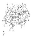
- FIG. 1is a perspective of an enteral feeding pump showing a fragmentary portion of a feeding set loaded in the pump;
- FIG. 2is a perspective of the pump without the feeding set
- FIG. 3is an elevation of the administration feeding set
- FIG. 4is a block diagram showing the elements of the pump and feeding set
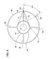
- FIG. 5is a perspective of a safety interlock device of the present invention.
- FIG. 6is an enlarged, fragmentary section of the pump and safety interlock device
- FIG. 7is a top plan view of FIG. 6 ;
- FIG. 8is a schematic diagram of FIG. 7 showing the reflection of electromagnetic radiation off the safety interlock device.
- an enteral feeding pump(broadly, “a pumping apparatus”) constructed according to the principles of the present invention is generally indicated at 1 .
- the feeding pumpcomprises a housing generally indicated at 3 that is constructed so as to mount an administration feeding set (broadly, a “pump set”) generally indicated at 5 (see FIGS. 1 and 3 ).
- housingas used herein may include many forms of supporting structures (not shown), including without limitation multi-part structures and structures that do not enclose or house the working components of the pump 1 .
- the pump 1also has a display screen 9 on the front of the housing 3 that is capable of displaying information about the status and/or operation of the pump.
- Buttons 11 on the side of the display screen 9are provided for use in controlling and obtaining information from the pump 1 .
- the illustrated pump 1is an enteral feeding pump, the present invention has application to other types of peristaltic pumps (not shown), including medical infusion pumps.
- a pump of the same general type as described hereinis shown in co-assigned U.S. Pat. No. 4,909,797 entitled ENTERAL DELIVERY SET WITH SHADED DRIP CHAMBER, the disclosure of which is incorporated herein by reference.
- the enteral feeding pump 1further includes a pumping unit (indicated generally at 23 ) comprising a pump motor 25 located in the housing 3 and shown schematically in FIG. 4 .
- An electrical cord 27extends from the housing 3 for connection to a source of electrical power for the motor 25 .
- a battery(not shown) may be received in the housing 3 for powering the pump motor 25 .
- the pumping unit 23further includes a rotor (generally indicated at 37 ) mounted on a rotor shaft (not shown) of the pumping unit.
- the rotor 37includes an inner disk 39 , an outer disk 41 and three rollers 43 (only one is shown) mounted between the inner and outer disks for rotation about their longitudinal axes relative to the disks.
- the pump motor 25 , rotor shaft and rotor 37may broadly be considered “a pumping device”.
- the pump housing 3includes a first lower recess 45 above the rotor 37 and a second lower recess 47 generally adjacent the first lower recess.
- the housing 3has an upper recess 49 generally axially aligned with the first lower recess 45 and a shoulder 51 at the bottom of the upper recess for receiving and holding part of the feeding set 5 .
- a curved recess 53 in the housing 3 above the second lower recess 47receives and holds another part of the administration feeding set 5 in place.
- the lower recesses 45 , 47 , upper recess 49 and curved recess 51may broadly be considered, individually or as a group, “a receiving portion” of the housing 3 that receives parts of the administration feeding set 5 in a manner that will be described in more detail hereinafter.
- the administration feeding set 5comprises tubing (broadly, “a conduit”) indicated generally at 55 that provides a fluid pathway between at least one source of fluid and a patient.
- Tubing 55can be made of a medical grade, deformable silicone and comprises first tube section 57 connected between a drip chamber 59 and a safety interlock device, generally indicated at 61 .
- a second tube section 63is connected to the safety interlock device 61 and at an outlet of the tubing 55 to a connector, such as a barbed connector 65 , suitable for connection to a gastrostomy device (not shown) attached to a patient.
- Third tube section 67is connected at an inlet of the tubing 55 to a bag 69 of nutrient liquid and to the drip chamber 59 .
- pump sets of different constructionsmay be used, for example a recertification set (not shown) may be used to verify and/or correct the pump accuracy.
- the pump 1can be configured to automatically recognize what kind of set is installed and to alter its operation to conform to that called for by the particular pump set. Still further, the pump 1 can be configured to detect with sensors whether the first tube section 57 is properly installed on the pump.
- the safety interlock device 61connects first tube section 57 and the second tube section 63 of the administration feeding set 5 .
- the safety interlock device 61has a central axial bore 81 to allow the flow of fluid between the first tube section 57 and the second tube section 63 ( FIG. 6 ).
- the safety interlock device 61has an upper central tubular portion 83 that receives a portion of the tube 57 and a lower central tubular portion 89 that is received in the second tube section 63 for attaching the second tube section to the safety interlock device.
- a spoked connector portion 87extends radially outwardly from the central tubular portions 83 , 89 to an outer ring portion 88 .
- the spoked connector portion 87includes a connector ring 84 received around the central tubular portions 83 , 89 and spokes 86 extending radially outwardly from the connector ring to the outer ring portion 88 .
- the outer ring portion 88is spaced radially outwardly from the central tubular portions 83 , 89 and in opposed relation with at least a portion of the central tubular portions.
- the safety interlock device 61and in particular the central tubular portions 83 , 89 may be separate from the administration feeding set 5 , and/or may be attached to the administration feeding set in such a way that liquid does not pass through the safety interlock device.
- the outer ring potion 88is sized to be received on a seat, indicated generally at 91 ( FIG. 2 ), formed at the bottom of the second lower recess 47 in the pump 1 when the administration feeding set 5 is properly loaded on the pump ( FIG. 1 ).
- the seat 91is generally semi-cylindrical to correspond with the shape of the safety interlock device 61 and includes an axially facing surface 95 in the second lower recess 47 and a radially facing surface 99 in the second lower recess 47 .
- proper functioning of the pump 1is generally achieved when the central tubular portions 83 , 89 are seated in substantially face-to-face relation with the axially facing surface 95 of the seat 91 .
- the rotational orientation of the safety interlock 61 , within the seat 91 , about its axisis generally not pertinent to operation. Other ways of positioning the safety interlock 61 may be used within the scope of the present invention.
- the safety interlock device 61 and the seat 91 in the housing 3may be shaped to prevent the administration feeding set 5 from being accidentally dislodged and to prevent the use of non-compliant feeding sets that do not have the safety interlock device.
- the safety interlock device 61 and seat 91are generally cylindrical in shape but it is understood that other shapes (e.g., hex-shaped) may be used for the safety interlock device and the seat.
- the pump 1can be programmed or otherwise controlled for operation in a desired manner. For instance, the pump 1 can begin operation to provide feeding fluids from bag 69 to the patient.
- the care givermay select, for example, the amount of fluid to be delivered, the rate at which the fluid is to be delivered and the frequency of fluid delivery.
- the pump 1has a controller 77 (broadly, “a control system”) including a microprocessor 79 that allows it to accept programming and/or to include pre-programmed operational routines that can be initiated by the care giver.
- the microprocessor 79controls pump electronics 80 that operate the motor 25 .
- a software subsystem 82is used to determine if the feeding set 5 has been positioned properly on the pump 1 .
- the pump 1includes an infrared (“IR”) emitter 105 (broadly, “a source of electromagnetic radiation”) housed in the second lower recess 47 .
- the IR emitter 105is operatively connected to the controller 77 for emitting an electromagnetic signal having a (“first”) wavelength in the infrared range in a direction for striking the safety interlock device 61 of the feeding set 5 .
- the source of electromagnetic radiationis an infrared (IR) emitter 105 but it is understood that other types of sources of electromagnetic radiation may be used without departing from the scope of this invention.
- An infrared (“IR”) detector 109 located in the second lower recess 47is operatively connected to the controller 77 for receiving the infrared signal from the IR emitter 105 and providing an indication to the controller that the feeding set 5 is properly positioned in the pump 1 .
- the IR detector 109(broadly, “a first sensor”) detects infrared radiation but it is understood that electromagnetic radiation sensors that detect other types of electromagnetic radiation may be used without departing from the scope of this invention.
- the IR detector 109distinguishes infrared radiation from other types of electromagnetic radiation (e.g., visible or ultraviolet light).
- a visible light emitter 107(broadly, “a second source of electromagnetic radiation”) may be housed in the second lower recess 47 .
- the visible light emitter 107is operatively connected to the controller 77 for emitting an electromagnetic signal having a (“second”) wavelength in the visible range in a direction for striking the safety interlock device 61 of the feeding set 5 .
- the source of electromagnetic radiationis a visible light emitter 107 but it is understood that other types of sources of electromagnetic radiation may be used without departing from the scope of this invention.
- a visible light detector 111(broadly, “a second electromagnetic radiation detector” and “a second sensor”) is housed in the second lower recess 47 generally adjacent the IR detector 109 and opposite the visible light emitter 107 .
- the visible light detector 111provides a signal to the controller 77 when visible light from the surrounding environment (e.g., electromagnetic radiation of a second wavelength) is detected to indicate that the safety interlock device 61 is not mounted in the second lower recess 47 in a position that blocks visible light from reaching the detector.
- the visible light detector 111is configured to detect electromagnetic radiation in the visible range, but not to detect electromagnetic radiation outside the visible range (e.g., infrared radiation).
- a second electromagnetic radiation detectorcould be configured to detect electromagnetic radiation in other ranges, such as in the ultraviolet range.
- the visible light detector 111can distinguish visible light from infrared radiation.
- electromagnetic radiation of a “first” or “second” wavelengthis intended in each case to encompass a range of wavelengths, such as wavelengths falling in the infrared range, visible range and/or ultraviolet range.
- the IR emitter 105is positioned in an alcove 113 in the second lower recess 47 of the housing 3 so that electromagnetic radiation (indicated by arrows Al in FIG. 7 ) from the emitter is directed to the upper central tubular portion 83 of the safety interlock device 61 (see also, FIG. 6 ).
- the infrared radiation from the IR emitter 105is reflected off of the upper central tubular portion 83 so that the infrared radiation is directed to and detected by the IR detector 109 .
- the connector portion 87 and outer ring portion 88are disposed generally within a common horizontal plane when the safety interlock 61 is mounted in the pump 1 .
- the connector portion 87 and outer ring portion 88are located out of the path of, or above, the radiation emitted from the IR emitter 105 when the safety interlock 61 is properly located on the seat 91 .
- the connector portion 87 and outer ring portioncould be located in the path of the radiation emitted from the IR emitter 105 or below the IR emitter.
- the IR detectoris positioned in an alcove 117 in the radially facing surface 99 of the seat 91 , the visible light emitter 107 is positioned in an alcove 115 , and the visible light detector 111 is positioned in an alcove 119 .
- the alcoves 113 , 115 , 117 , 119recess the IR emitter 105 , visible light emitter 107 , and the IR and visible light detectors 109 , 111 to protect them from physical contact with the safety interlock device 61 .
- a clear plastic windowmay enclose each of the emitters 105 , 107 and the detectors 109 , 111 within their corresponding alcoves 113 , 115 , 117 , 119 for additional protection.
- the alcoves 117 and 119help to shield the detectors 109 and 111 from ambient electromagnetic radiation (which may include both visible light and infrared radiation).
- the IR emitter 105is located approximately 49 degrees from the IR detector 109 .
- the infrared radiation from the IR emitter 105is not detected by the IR detector 109 .
- visible light from outside of the pump 1i.e., ambient light
- visible light from the visible light emitter 107may enter the second lower recess 47 and is detected by the visible light detector 111 .
- the central tubular portions 83 , 89are preferably constructed of a material that reflects infrared radiation, but is opaque to visible light.
- the connector portion 87 and outer ring portion 88are preferably constructed of a material that is transparent to infrared radiation and visible light such as clear plastic. However, the outer ring portion 88 and/or connector portion 87 could be made of material that will not transmit visible light, but will transmit infrared radiation.
- the central tubular portions 83 , 89are monolithic or formed by a single piece construction. However, the central tubular portions 83 , 89 could be formed from separate pieces and attached together by a suitable means.
- the IR emitter 105emits infrared radiation in a cone toward the side of the upper central tubular portion 83 .
- the IR emitter 105is arranged generally perpendicular to the central tubular portions 83 , 89 .
- the centerline CL of the coneis denoted in the drawing.
- a ray R 1 of radiationthat is a bisector of approximately one half of the cone.
- the ray R 1is representative of the nominal path of infrared radiation in this half of the cone.
- the other half of the conei.e., that portion above the centerline CL in FIG.
- the IR detector 109is preferably positioned here, or in a range of around 0-50 degrees. In another embodiment of the present invention (not shown), an IR detector is positioned about 60 degrees from the IR emitter.
- the administration feeding set feeding fluid bag 69can be hung from a suitable support, such as an IV pole (not shown).
- the drip chamber 59can be placed in the first lower recess 45 and upper recess 49 in an operating position as shown in FIG. 1 .
- the first tube section 57is placed around the lower part of the rotor 37 and the safety interlock device 61 is placed on the seat 91 at the bottom of the second lower recess 47 .
- the seat 91 in the second lower recess 47is generally located so that the safety interlock device 61 can be placed into the second lower recess at a location in which the first tube section 57 is substantially stretched around the rotor 37 .
- the IR emitter 105 and IR detector 109may intermittently or continuously check for the presence of the properly loaded feeding set 5 .
- the infrared signal from the IR emitter 105is directed to the upper central tubular portion 83 .
- the central tubular portionreflects the infrared signal from the IR emitter on to the IR detector 109 (see FIGS. 7 and 8 ).
- the IR detectoris periodically operated and detects the presence of infrared radiation when the feeding set 5 has been properly loaded on the pump. It is understood that the IR detector 109 is preferably unable to detect electromagnetic radiation having a wavelength in the visible light region of the electromagnetic spectrum.
- the IR detector 109Upon detection of the infrared signal, the IR detector 109 sends a corresponding signal to the microprocessor 79 . Also, when the safety interlock device 61 is loaded onto the seat 91 , visible light from ambient light and from the visible light emitter 107 is blocked by the central tubular portions 83 , 89 from reaching the visible light detector 111 . When the set 5 is loaded, the visible light detector 111 sends a signal to the microprocessor 79 to indicate that visible light is blocked and the pump 1 may be operated.
Landscapes
- Engineering & Computer Science (AREA)
- Health & Medical Sciences (AREA)
- Mechanical Engineering (AREA)
- General Engineering & Computer Science (AREA)
- Biomedical Technology (AREA)
- Anesthesiology (AREA)
- Vascular Medicine (AREA)
- Heart & Thoracic Surgery (AREA)
- Hematology (AREA)
- Life Sciences & Earth Sciences (AREA)
- Animal Behavior & Ethology (AREA)
- General Health & Medical Sciences (AREA)
- Public Health (AREA)
- Veterinary Medicine (AREA)
- Infusion, Injection, And Reservoir Apparatuses (AREA)
Abstract
Description
This application is a continuation application of and claims the benefit of priority under 35 U.S.C. §120 to U.S. patent application Ser. No. 12/777,357, filed May 11, 2010, which is hereby incorporated by reference for all purposes.
The present invention generally relates to a pump set for delivering fluids to a patient by way of a flow control apparatus, and more particularly to a pump set having a safety interlock device for determining secure loading of the pump set on the flow control apparatus.
Administering fluids containing medicine or nutrition to a patient is well known in the art. Fluids can be delivered to patients by gravity flow, but often are delivered to the patient by a pump set loaded on a flow control apparatus, such as a peristaltic pump, which delivers fluid to the patient at a controlled rate of delivery. A peristaltic pump usually comprises a housing that includes a rotor or the like operatively engaged to at least one motor through a gearbox. The rotor drives fluid through the tubing of the pump set by the peristaltic action effected by rotation of the rotor by the motor. The motor is operatively connected to a rotatable shaft that drives the rotor, which in turn progressively compresses the tubing and drives the fluid at a controlled rate through the pump set. A controller operates the motor to drive the rotor. Other types of peristaltic pumps not employing rotors are also known.
In order for the pump to deliver an accurate amount of fluid corresponding with the flow parameters programmed into the pump, the administration feeding set must be correctly loaded on the pump. If the pump set is misaligned in the pump, the pump may deliver an inaccurate amount of fluid to a patient or the pump generates a low flow alarm requiring the condition to be examined and the set reloaded. Existing pumps have systems to detect whether the pump set is properly loaded. An example of such a pump having a detection system is shown in co-assigned U.S. Pat. No. 4,913,703, entitled SAFETY INTERLOCK SYSTEM FOR MEDICAL FLUID PUMPS and U.S. Publication No. 2007/0253833, entitled PUMP SET WITH SAFETY INTERLOCK, the disclosures of which are incorporated by reference.
In one aspect, a safety interlock for use in a medical device having a control system for controlling operation of the medical device generally comprises a central tubular portion defining a fluid passage for passing fluid through the safety interlock. An outer ring portion is adapted for mounting the safety interlock in the medical device. A spoked connector portion connects the central tubular portion to the outer ring portion so that the outer ring portion is spaced radially outwardly from the central tubular portion in opposed relation with at least a portion of the central tubular portion. The safety interlock is adapted for mounting in the medical device in a path of electromagnetic radiation from a source of electromagnetic radiation such that the central tubular portion reflects the electromagnetic radiation to an electromagnetic radiation detector when properly loaded in the medical device.
Other objects and features will be in part apparent and in part pointed out hereinafter.
Corresponding reference characters indicate corresponding parts throughout the drawings.
Referring now to the drawings, an enteral feeding pump (broadly, “a pumping apparatus”) constructed according to the principles of the present invention is generally indicated at1. The feeding pump comprises a housing generally indicated at3 that is constructed so as to mount an administration feeding set (broadly, a “pump set”) generally indicated at5 (seeFIGS. 1 and3). It will be appreciated that “housing” as used herein may include many forms of supporting structures (not shown), including without limitation multi-part structures and structures that do not enclose or house the working components of thepump 1. Thepump 1 also has adisplay screen 9 on the front of thehousing 3 that is capable of displaying information about the status and/or operation of the pump.Buttons 11 on the side of thedisplay screen 9 are provided for use in controlling and obtaining information from thepump 1. It will be understood that although the illustratedpump 1 is an enteral feeding pump, the present invention has application to other types of peristaltic pumps (not shown), including medical infusion pumps. A pump of the same general type as described herein is shown in co-assigned U.S. Pat. No. 4,909,797 entitled ENTERAL DELIVERY SET WITH SHADED DRIP CHAMBER, the disclosure of which is incorporated herein by reference.
Theenteral feeding pump 1 further includes a pumping unit (indicated generally at23) comprising apump motor 25 located in thehousing 3 and shown schematically inFIG. 4 . Anelectrical cord 27 extends from thehousing 3 for connection to a source of electrical power for themotor 25. Alternatively, or in addition, a battery (not shown) may be received in thehousing 3 for powering thepump motor 25. Thepumping unit 23 further includes a rotor (generally indicated at37) mounted on a rotor shaft (not shown) of the pumping unit. Therotor 37 includes aninner disk 39, anouter disk 41 and three rollers43 (only one is shown) mounted between the inner and outer disks for rotation about their longitudinal axes relative to the disks. In the illustrated embodiment, thepump motor 25, rotor shaft androtor 37 may broadly be considered “a pumping device”. Thepump housing 3 includes a firstlower recess 45 above therotor 37 and a secondlower recess 47 generally adjacent the first lower recess. Thehousing 3 has anupper recess 49 generally axially aligned with the firstlower recess 45 and ashoulder 51 at the bottom of the upper recess for receiving and holding part of thefeeding set 5. Acurved recess 53 in thehousing 3 above the secondlower recess 47 receives and holds another part of the administration feedingset 5 in place. Thelower recesses upper recess 49 andcurved recess 51 may broadly be considered, individually or as a group, “a receiving portion” of thehousing 3 that receives parts of the administration feeding set5 in a manner that will be described in more detail hereinafter.
Referring now toFIG. 3 , theadministration feeding set 5 comprises tubing (broadly, “a conduit”) indicated generally at55 that provides a fluid pathway between at least one source of fluid and a patient.Tubing 55 can be made of a medical grade, deformable silicone and comprisesfirst tube section 57 connected between adrip chamber 59 and a safety interlock device, generally indicated at61. Asecond tube section 63 is connected to thesafety interlock device 61 and at an outlet of thetubing 55 to a connector, such as abarbed connector 65, suitable for connection to a gastrostomy device (not shown) attached to a patient.Third tube section 67 is connected at an inlet of thetubing 55 to abag 69 of nutrient liquid and to thedrip chamber 59. As previously stated, pump sets of different constructions may be used, for example a recertification set (not shown) may be used to verify and/or correct the pump accuracy. Thepump 1 can be configured to automatically recognize what kind of set is installed and to alter its operation to conform to that called for by the particular pump set. Still further, thepump 1 can be configured to detect with sensors whether thefirst tube section 57 is properly installed on the pump.
As shown inFIG. 3 , thesafety interlock device 61 connectsfirst tube section 57 and thesecond tube section 63 of theadministration feeding set 5. Thesafety interlock device 61 has a centralaxial bore 81 to allow the flow of fluid between thefirst tube section 57 and the second tube section63 (FIG. 6 ). Referring toFIGS. 5 and 6 , thesafety interlock device 61 has an upper centraltubular portion 83 that receives a portion of thetube 57 and a lower centraltubular portion 89 that is received in thesecond tube section 63 for attaching the second tube section to the safety interlock device. Aspoked connector portion 87 extends radially outwardly from the centraltubular portions outer ring portion 88. Thespoked connector portion 87 includes aconnector ring 84 received around the centraltubular portions spokes 86 extending radially outwardly from the connector ring to theouter ring portion 88. Thus, theouter ring portion 88 is spaced radially outwardly from the centraltubular portions safety interlock device 61, and in particular the centraltubular portions
Theouter ring potion 88 is sized to be received on a seat, indicated generally at91 (FIG. 2 ), formed at the bottom of the secondlower recess 47 in thepump 1 when the administration feeding set5 is properly loaded on the pump (FIG. 1 ). In the illustrated embodiment, theseat 91 is generally semi-cylindrical to correspond with the shape of thesafety interlock device 61 and includes anaxially facing surface 95 in the secondlower recess 47 and aradially facing surface 99 in the secondlower recess 47. In this embodiment, proper functioning of thepump 1 is generally achieved when the centraltubular portions axially facing surface 95 of theseat 91. The rotational orientation of thesafety interlock 61, within theseat 91, about its axis is generally not pertinent to operation. Other ways of positioning thesafety interlock 61 may be used within the scope of the present invention. Thesafety interlock device 61 and theseat 91 in thehousing 3 may be shaped to prevent the administration feeding set5 from being accidentally dislodged and to prevent the use of non-compliant feeding sets that do not have the safety interlock device. In the illustrated embodiment, thesafety interlock device 61 andseat 91 are generally cylindrical in shape but it is understood that other shapes (e.g., hex-shaped) may be used for the safety interlock device and the seat.
Thepump 1 can be programmed or otherwise controlled for operation in a desired manner. For instance, thepump 1 can begin operation to provide feeding fluids frombag 69 to the patient. The care giver may select, for example, the amount of fluid to be delivered, the rate at which the fluid is to be delivered and the frequency of fluid delivery. As shown inFIG. 4 , thepump 1 has a controller77 (broadly, “a control system”) including amicroprocessor 79 that allows it to accept programming and/or to include pre-programmed operational routines that can be initiated by the care giver. Themicroprocessor 79 controls pumpelectronics 80 that operate themotor 25. Asoftware subsystem 82 is used to determine if the feeding set5 has been positioned properly on thepump 1.
Referring toFIGS. 4 ,6 and7, thepump 1 includes an infrared (“IR”) emitter105 (broadly, “a source of electromagnetic radiation”) housed in the secondlower recess 47. TheIR emitter 105 is operatively connected to thecontroller 77 for emitting an electromagnetic signal having a (“first”) wavelength in the infrared range in a direction for striking thesafety interlock device 61 of the feeding set5. In the illustrated embodiment, the source of electromagnetic radiation is an infrared (IR) emitter105 but it is understood that other types of sources of electromagnetic radiation may be used without departing from the scope of this invention. An infrared (“IR”)detector 109 located in the secondlower recess 47 is operatively connected to thecontroller 77 for receiving the infrared signal from theIR emitter 105 and providing an indication to the controller that the feeding set5 is properly positioned in thepump 1. In the illustrated embodiment, the IR detector109 (broadly, “a first sensor”) detects infrared radiation but it is understood that electromagnetic radiation sensors that detect other types of electromagnetic radiation may be used without departing from the scope of this invention. TheIR detector 109 distinguishes infrared radiation from other types of electromagnetic radiation (e.g., visible or ultraviolet light).
A visible light emitter107(broadly, “a second source of electromagnetic radiation”) may be housed in the secondlower recess 47. Thevisible light emitter 107 is operatively connected to thecontroller 77 for emitting an electromagnetic signal having a (“second”) wavelength in the visible range in a direction for striking thesafety interlock device 61 of the feeding set5. In the illustrated embodiment, the source of electromagnetic radiation is avisible light emitter 107 but it is understood that other types of sources of electromagnetic radiation may be used without departing from the scope of this invention. A visible light detector111 (broadly, “a second electromagnetic radiation detector” and “a second sensor”) is housed in the secondlower recess 47 generally adjacent theIR detector 109 and opposite thevisible light emitter 107. Thevisible light detector 111 provides a signal to thecontroller 77 when visible light from the surrounding environment (e.g., electromagnetic radiation of a second wavelength) is detected to indicate that thesafety interlock device 61 is not mounted in the secondlower recess 47 in a position that blocks visible light from reaching the detector. Preferably, thevisible light detector 111 is configured to detect electromagnetic radiation in the visible range, but not to detect electromagnetic radiation outside the visible range (e.g., infrared radiation). A second electromagnetic radiation detector could be configured to detect electromagnetic radiation in other ranges, such as in the ultraviolet range. Thus, thevisible light detector 111 can distinguish visible light from infrared radiation. As used herein, electromagnetic radiation of a “first” or “second” wavelength is intended in each case to encompass a range of wavelengths, such as wavelengths falling in the infrared range, visible range and/or ultraviolet range.
Other sensors (not shown), such as a sensor that determines the type of pump set that has been placed in thepump 1 and a flow monitoring sensor can be in communication with thecontroller 77 to facilitate accurate operation of the pump. TheIR emitter 105 is positioned in analcove 113 in the secondlower recess 47 of thehousing 3 so that electromagnetic radiation (indicated by arrows Al inFIG. 7 ) from the emitter is directed to the upper centraltubular portion 83 of the safety interlock device61 (see also,FIG. 6 ). When thesafety interlock device 61 is properly located on theseat 91, the infrared radiation from theIR emitter 105 is reflected off of the upper centraltubular portion 83 so that the infrared radiation is directed to and detected by theIR detector 109. Theconnector portion 87 andouter ring portion 88 are disposed generally within a common horizontal plane when thesafety interlock 61 is mounted in thepump 1. In the illustrated embodiment, theconnector portion 87 andouter ring portion 88 are located out of the path of, or above, the radiation emitted from theIR emitter 105 when thesafety interlock 61 is properly located on theseat 91. However, theconnector portion 87 and outer ring portion could be located in the path of the radiation emitted from theIR emitter 105 or below the IR emitter.
The IR detector is positioned in analcove 117 in theradially facing surface 99 of theseat 91, thevisible light emitter 107 is positioned in analcove 115, and thevisible light detector 111 is positioned in analcove 119. Thealcoves IR emitter 105,visible light emitter 107, and the IR and visiblelight detectors safety interlock device 61. Although not shown, a clear plastic window may enclose each of theemitters detectors alcoves alcoves detectors
In the illustrated embodiment, theIR emitter 105 is located approximately 49 degrees from theIR detector 109. When the feeding set5 is not loaded in the secondlower recess 47 and thesafety interlock device 61 is not received on theseat 91, the infrared radiation from theIR emitter 105 is not detected by theIR detector 109. Also when thesafety interlock device 61 is not received on theseat 91, visible light from outside of the pump1 (i.e., ambient light) and/or visible light from thevisible light emitter 107 may enter the secondlower recess 47 and is detected by thevisible light detector 111. The centraltubular portions connector portion 87 andouter ring portion 88 are preferably constructed of a material that is transparent to infrared radiation and visible light such as clear plastic. However, theouter ring portion 88 and/orconnector portion 87 could be made of material that will not transmit visible light, but will transmit infrared radiation. In the illustrated embodiment, the centraltubular portions tubular portions
Referring now toFIG. 8 , reflection of infrared radiation off of the upper centraltubular portion 83 is schematically illustrated. TheIR emitter 105 emits infrared radiation in a cone toward the side of the upper centraltubular portion 83. TheIR emitter 105 is arranged generally perpendicular to the centraltubular portions FIG. 8 ) is believed to be of small or no use in providing a light signal capable of being detected by theIR detector 109. The ray R1 strikes the side of the upper centraltubular portion 83 at an angle. The ray R1 is reflected back toward the side of therecess 47. Finally, the ray R1 strikes the side of therecess 47 at a location that is about 49 degrees away from the location of theIR emitter 105. Accordingly, theIR detector 109 is preferably positioned here, or in a range of around 0-50 degrees. In another embodiment of the present invention (not shown), an IR detector is positioned about 60 degrees from the IR emitter.
In use, the administration feeding set feedingfluid bag 69 can be hung from a suitable support, such as an IV pole (not shown). Thedrip chamber 59 can be placed in the firstlower recess 45 andupper recess 49 in an operating position as shown inFIG. 1 . Thefirst tube section 57 is placed around the lower part of therotor 37 and thesafety interlock device 61 is placed on theseat 91 at the bottom of the secondlower recess 47. Theseat 91 in the secondlower recess 47 is generally located so that thesafety interlock device 61 can be placed into the second lower recess at a location in which thefirst tube section 57 is substantially stretched around therotor 37. TheIR emitter 105 andIR detector 109 may intermittently or continuously check for the presence of the properly loaded feeding set5. When thesafety interlock device 61 is received in a proper operating position on theseat 91, the infrared signal from theIR emitter 105 is directed to the upper centraltubular portion 83. The central tubular portion reflects the infrared signal from the IR emitter on to the IR detector109 (seeFIGS. 7 and 8 ). The IR detector is periodically operated and detects the presence of infrared radiation when the feeding set5 has been properly loaded on the pump. It is understood that theIR detector 109 is preferably unable to detect electromagnetic radiation having a wavelength in the visible light region of the electromagnetic spectrum. Upon detection of the infrared signal, theIR detector 109 sends a corresponding signal to themicroprocessor 79. Also, when thesafety interlock device 61 is loaded onto theseat 91, visible light from ambient light and from thevisible light emitter 107 is blocked by the centraltubular portions visible light detector 111. When theset 5 is loaded, thevisible light detector 111 sends a signal to themicroprocessor 79 to indicate that visible light is blocked and thepump 1 may be operated.
Having described the invention in detail, it will be apparent that modifications and variations are possible without departing from the scope of the invention defined in the appended claims.
When introducing elements of the present invention or the preferred embodiments(s) thereof, the articles “a”, “an”, “the” and “said” are intended to mean that there are one or more of the elements. The terms “comprising”, “including” and “having” are intended to be inclusive and mean that there may be additional elements other than the listed elements.
In view of the above, it will be seen that the several objects of the invention are achieved and other advantageous results attained.
As various changes could be made in the above constructions without departing from the scope of the invention, it is intended that all matter contained in the above description and shown in the accompanying drawings shall be interpreted as illustrative and not in a limiting sense.
Claims (9)
1. A safety interlock for use in a medical device having a control system for controlling operation of the medical device, a source of electromagnetic radiation operatively connected to the control system of the medical device for emitting electromagnetic radiation, and an electromagnetic radiation detector operatively connected to the control system for providing an indication that the safety interlock is properly loaded on the medical device, the safety interlock comprising:
a central tubular portion defining a fluid passage for passing fluid through the safety interlock;
an outer ring portion adapted for mounting the safety interlock in the medical device; and
a spoked connector portion connecting the central tubular portion to the outer ring portion so that the outer ring portion is spaced radially outwardly from the central tubular portion in opposed relation with at least a portion of the central tubular portion;
the safety interlock being adapted for mounting in the medical device in a path of the electromagnetic radiation from the source of electromagnetic radiation such that the central tubular portion reflects the electromagnetic radiation to the electromagnetic radiation detector when properly loaded in the medical device.
2. The safety interlock ofclaim 1 , wherein the outer ring portion and the spoked connector portion are centered about a common horizontal plane extending orthogonal to a longitudinal axis of the central tubular portion when the safety interlock is mounted in the medical device.
3. The safety interlock ofclaim 2 , wherein the outer ring portion does not inhibit propagation of the electromagnetic radiation from the source of electromagnetic radiation when the safety interlock is mounted in the medical device.
4. The safety interlock ofclaim 3 , wherein the outer ring portion and the spoked connector portion are substantially transparent to both infrared radiation and visible light.
5. The safety interlock ofclaim 1 , wherein the spoked connector portion comprises a connector ring received around the central tubular portion and spokes extending radially outwardly from the connector ring to the outer ring portion.
6. The safety interlock ofclaim 5 , wherein the spoked connector portion comprises at least two spokes.
7. The safety interlock ofclaim 6 , wherein the spoked connector portion comprises four spokes.
8. The safety interlock ofclaim 1 , wherein the spoked connector portion is formed at least in part by two separate spokes.
9. The safety interlock ofclaim 1 , in combination with the medical device.
Priority Applications (1)
| Application Number | Priority Date | Filing Date | Title |
|---|---|---|---|
| US13/416,837US8760146B2 (en) | 2010-05-11 | 2012-03-09 | Safety interlock |
Applications Claiming Priority (2)
| Application Number | Priority Date | Filing Date | Title |
|---|---|---|---|
| US12/777,357US8154274B2 (en) | 2010-05-11 | 2010-05-11 | Safety interlock |
| US13/416,837US8760146B2 (en) | 2010-05-11 | 2012-03-09 | Safety interlock |
Related Parent Applications (1)
| Application Number | Title | Priority Date | Filing Date |
|---|---|---|---|
| US12/777,357ContinuationUS8154274B2 (en) | 2010-05-11 | 2010-05-11 | Safety interlock |
Publications (2)
| Publication Number | Publication Date |
|---|---|
| US20120172801A1 US20120172801A1 (en) | 2012-07-05 |
| US8760146B2true US8760146B2 (en) | 2014-06-24 |
Family
ID=44510075
Family Applications (2)
| Application Number | Title | Priority Date | Filing Date |
|---|---|---|---|
| US12/777,357Active2030-06-23US8154274B2 (en) | 2010-05-11 | 2010-05-11 | Safety interlock |
| US13/416,837Active2030-09-27US8760146B2 (en) | 2010-05-11 | 2012-03-09 | Safety interlock |
Family Applications Before (1)
| Application Number | Title | Priority Date | Filing Date |
|---|---|---|---|
| US12/777,357Active2030-06-23US8154274B2 (en) | 2010-05-11 | 2010-05-11 | Safety interlock |
Country Status (8)
| Country | Link |
|---|---|
| US (2) | US8154274B2 (en) |
| EP (1) | EP2399622A1 (en) |
| JP (1) | JP5306409B2 (en) |
| CN (3) | CN102258815B (en) |
| AU (1) | AU2011201858B2 (en) |
| CA (1) | CA2737170C (en) |
| IL (1) | IL212336A0 (en) |
| MX (1) | MX2011004359A (en) |
Cited By (1)
| Publication number | Priority date | Publication date | Assignee | Title |
|---|---|---|---|---|
| US20140014095A1 (en)* | 2012-07-11 | 2014-01-16 | Nellcor Puritan Bennett Llc | Tracheal tube with inner cannula indication system |
Families Citing this family (3)
| Publication number | Priority date | Publication date | Assignee | Title |
|---|---|---|---|---|
| US9078964B2 (en) | 2008-08-21 | 2015-07-14 | Sur-Real Industries, Inc. | Pump device, tube device and method for movement and collection of fluid |
| US10113542B2 (en) | 2012-05-24 | 2018-10-30 | Cook Medical Technologies Llc | Peristaltic pump tubing securing system |
| USD809909S1 (en) | 2013-03-15 | 2018-02-13 | Cook Medical Technologies Llc | Tubing clips |
Citations (188)
| Publication number | Priority date | Publication date | Assignee | Title |
|---|---|---|---|---|
| US2483924A (en) | 1946-06-10 | 1949-10-04 | Moulinier Edmond Jean | Pump |
| US3432128A (en) | 1967-04-13 | 1969-03-11 | Walter J Elleboudt | Channel assembly for flexible tubing,conductors,and the like |
| US3435209A (en) | 1966-03-10 | 1969-03-25 | Beckman Instruments Inc | Two wavelength infrared analyzer having a pair of variable interference filters for determining the respective wavelengths |
| US3523179A (en) | 1969-03-27 | 1970-08-04 | Monsanto Co | Selective transmitter for infrared heaters |
| US3673476A (en) | 1971-03-08 | 1972-06-27 | Ford Motor Co | Signal producing apparatus adaptable for use with variable reluctance motors |
| US3675653A (en) | 1969-08-15 | 1972-07-11 | Air Shields | Wound drainage equipment |
| US3693025A (en) | 1969-11-28 | 1972-09-19 | Brun Sensor Systems Inc | Apparatus and method for eliminating interference errors in dual-beam infrared reflection measurements on a diffusely reflecting surface by geometrical elimination of interference-producing specularly-reflected radiation components |
| US3851976A (en) | 1972-01-26 | 1974-12-03 | J Meier | Method for determining the translucency and/or turbidity of a medium and apparatus for applying the method |
| US3982162A (en) | 1969-08-13 | 1976-09-21 | David William Olliffe | Centrifuges |
| US3985133A (en) | 1974-05-28 | 1976-10-12 | Imed Corporation | IV pump |
| US3987303A (en) | 1975-02-06 | 1976-10-19 | Hewlett-Packard Company | Medical-analytical gas detector |
| US3993061A (en) | 1975-02-28 | 1976-11-23 | Ivac Corporation | Syringe pump drive system and disposable syringe cartridge |
| US4038982A (en) | 1975-12-03 | 1977-08-02 | Burron Medical Products, Inc. | Electrically controlled intravenous infusion set |
| US4126132A (en) | 1975-07-28 | 1978-11-21 | Andros Incorporated | Intravenous and intra arterial delivery system |
| GB2065916A (en) | 1979-11-30 | 1981-07-01 | Kureha Chemical Ind Co Ltd | Infrared condensing lenses |
| US4300048A (en) | 1974-01-04 | 1981-11-10 | Commissariat A L'energie Atomique | Alarm detector responsive to rate change of a monitored condition |
| US4346296A (en) | 1980-08-15 | 1982-08-24 | Andros Analyzers Incorporated | Non-dispersive infrared gas analyzer |
| US4424011A (en) | 1980-12-22 | 1984-01-03 | Triune Automated Painting Systems | Painting applicator with remote supply |
| US4454763A (en) | 1982-08-12 | 1984-06-19 | Washington Research Foundation | Rotary ultrasonic scan head including fluid drive |
| ES8500067A1 (en) | 1984-01-19 | 1984-10-01 | Intermedicat Gmbh | Peristaltic hose pump for medical use |
| US4504263A (en) | 1982-12-22 | 1985-03-12 | Valleylab, Inc. | Flow rate monitor with optical sensing chamber |
| US4508422A (en) | 1982-03-03 | 1985-04-02 | Pharos Ab | Optical scanning system |
| US4525069A (en) | 1981-05-19 | 1985-06-25 | Horiba, Ltd. | Optical absorption analyzer |
| US4537561A (en) | 1983-02-24 | 1985-08-27 | Medical Technology, Ltd. | Peristaltic infusion pump and disposable cassette for use therewith |
| US4646144A (en) | 1985-02-09 | 1987-02-24 | Dainippon Screen Mfg. Co., Ltd. | Method and apparatus for reproducing color separation picture image |
| US4652260A (en) | 1985-03-11 | 1987-03-24 | Strato Medical Corporation | Infusion device |
| US4665391A (en) | 1986-02-27 | 1987-05-12 | Warner-Lambert Company | Empty container detector |
| US4714463A (en) | 1984-11-29 | 1987-12-22 | Minnesota Mining And Manufacturing Company | Sequence valve for piggyback IV administration with tube reversal prevention |
| US4720636A (en) | 1984-08-06 | 1988-01-19 | Abbott Laboratories | Drop detecting system which operates under different ambient light conditions |
| DE3627011A1 (en) | 1986-08-09 | 1988-02-18 | Huebner Karl Alexander | Air trap for shutting off plastic tubes, especially infusion tubes |
| US4763032A (en) | 1983-11-29 | 1988-08-09 | Fraunhofer-Gesellschaft Zur Forderung Der Angewandten Forschung E.V. | Magnetic rotor bearing |
| US4772273A (en) | 1985-12-13 | 1988-09-20 | Becton, Dickinson And Company | Variable-volume vented container |
| US4785322A (en) | 1987-12-10 | 1988-11-15 | Polaroid Corporation | Infrared wink ranging system |
| US4788444A (en) | 1985-12-18 | 1988-11-29 | Lucas Electrical Electronics And Systems Limited | Liquid level detection |
| US4792424A (en) | 1984-01-10 | 1988-12-20 | Loman Henricus G M | Method of injection molding PVC products |
| US4797655A (en) | 1986-03-24 | 1989-01-10 | Gambro Ab | Detector system for monitoring a fluid containing tube |
| US4806751A (en) | 1985-09-30 | 1989-02-21 | Alps Electric Co., Ltd. | Code wheel for a reflective type optical rotary encoder |
| US4845487A (en) | 1987-07-20 | 1989-07-04 | Frantz Medical Development Ltd. | Pump system for enteral/parenteral fluid control and delivery |
| US4845489A (en) | 1985-12-23 | 1989-07-04 | Chrysler Motors Corporation | Electroluminescent display drive circuitry |
| US4850807A (en) | 1987-06-16 | 1989-07-25 | Frantz Medical Development Ltd. | Disposable cassette for fluid delivery pump systems |
| US4878896A (en) | 1987-12-01 | 1989-11-07 | Pacesetter Infusion, Ltd. | Cassette optical identification apparatus for a medication infusion system |
| US4882575A (en) | 1987-01-28 | 1989-11-21 | Sharp Kabushiki Kaisha | Monitor for blocked condition in tube for fluid infusion pump |
| US4884065A (en) | 1988-06-13 | 1989-11-28 | Pacesetter Infusion, Ltd. | Monitor for detecting tube position and air bubbles in tube |
| US4884013A (en) | 1988-01-15 | 1989-11-28 | Sherwood Medical Company | Motor unit for a fluid pump and method of operation |
| US4909797A (en) | 1987-01-16 | 1990-03-20 | Sherwood Medical Company | Enteral delivery set with shaded drip chamber |
| US4913703A (en) | 1987-09-30 | 1990-04-03 | Sherwood Medical Company | Safety interlock system for medical fluid pumps |
| US4933563A (en) | 1987-08-26 | 1990-06-12 | U.S. Philips Corp. | Infra-red receiver |
| US4940050A (en) | 1985-10-11 | 1990-07-10 | Dornier Medizintechnik Gmbh | Device for ensuring the proper positioning of electrodes in a lithotripter |
| US4945244A (en) | 1988-12-23 | 1990-07-31 | Castleman Robert D | Electronic infrared detector |
| US4944748A (en) | 1986-10-12 | 1990-07-31 | Bramm Gunter W | Magnetically suspended and rotated rotor |
| US4950235A (en) | 1988-05-10 | 1990-08-21 | Pacesetter Infusion, Ltd. | Container-side occlusion detection system for a medication infusion system |
| US4958910A (en) | 1987-04-06 | 1990-09-25 | British Telecommunications Public Limited Company | Radiation pulse generation |
| DE3910250A1 (en) | 1989-03-30 | 1990-10-11 | Fresenius Ag | Photoelectric monitoring arrangement for hose lines in medical technology |
| US4976590A (en) | 1988-06-08 | 1990-12-11 | Baldwin Brian E | Fluid conduit-responsively adjustable pump arrangement and pump/conduit arrangement and method, and fluid conduits therefor |
| US5055001A (en) | 1990-03-15 | 1991-10-08 | Abbott Laboratories | Volumetric pump with spring-biased cracking valves |
| US5057081A (en) | 1990-06-15 | 1991-10-15 | Sherwood Medical Company | Peristaltic infusion device |
| US5058970A (en) | 1990-09-17 | 1991-10-22 | Eastman Kodak Company | Quasi-phase matching optical waveguide |
| US5101711A (en) | 1991-01-09 | 1992-04-07 | Durbin James W | Air flow diverter |
| US5181842A (en) | 1990-06-15 | 1993-01-26 | Sherwood Medical Company | Peristaltic infusion device |
| US5201711A (en) | 1987-09-30 | 1993-04-13 | Sherwood Medical Company | Safety interlock system for medical fluid pumps |
| US5207645A (en) | 1991-06-25 | 1993-05-04 | Medication Delivery Devices | Infusion pump, treatment fluid bag therefor, and method for the use thereof |
| US5211626A (en) | 1987-05-01 | 1993-05-18 | Product Innovation Holdings Ltd. | Medical infusion apparatus |
| US5237450A (en) | 1989-08-23 | 1993-08-17 | Stroemberg Rolf | Inertial stabilizing system |
| US5250027A (en) | 1991-10-08 | 1993-10-05 | Sherwood Medical Company | Peristaltic infusion device with backpack sensor |
| US5256155A (en) | 1991-04-01 | 1993-10-26 | Sherwood Medical Company | Drop detection method and apparatus |
| US5330431A (en) | 1993-03-12 | 1994-07-19 | Glenn Herskowitz | Infusion pump |
| US5336174A (en) | 1992-05-07 | 1994-08-09 | Ivac Corporation | Flow control valve |
| US5352364A (en) | 1990-08-20 | 1994-10-04 | Abbott Laboratories | Medical drug formulation and delivery system and reverse osmosis purification device |
| US5357113A (en) | 1992-11-18 | 1994-10-18 | Liston Scientific Corp. | Infrared gas mixture analyzer |
| US5364364A (en) | 1993-08-04 | 1994-11-15 | Ivac Corporation | Automatic flow control valve system |
| US5383858A (en) | 1992-08-17 | 1995-01-24 | Medrad, Inc. | Front-loading medical injector and syringe for use therewith |
| EP0467805B1 (en) | 1990-07-17 | 1995-03-15 | Hospal Ag | Equipment for detecting the presence of a tube and/or the presence of fluid within it |
| US5415641A (en) | 1991-04-01 | 1995-05-16 | Sherwood Medical Company | Drop detection method and apparatus |
| US5433588A (en) | 1993-12-15 | 1995-07-18 | Stryker Corporation | Peristaltic pump with one piece tubing insert and one piece cover |
| US5436455A (en) | 1990-06-27 | 1995-07-25 | Futrex Inc. | Non-invasive near-infrared quantitative measurement instrument |
| US5437635A (en) | 1992-05-06 | 1995-08-01 | Mcgaw, Inc. | Tube flow limiter, safety flow clip, and tube pincher mechanism |
| US5502111A (en) | 1991-03-06 | 1996-03-26 | E. I. Du Pont De Nemours And Company | Process for making polyvinyl chloride compositions having high heat distortion temperatures |
| US5508521A (en) | 1994-12-05 | 1996-04-16 | Cardiovascular Diagnostics Inc. | Method and apparatus for detecting liquid presence on a reflecting surface using modulated light |
| US5531697A (en) | 1994-04-15 | 1996-07-02 | Sims Deltec, Inc. | Systems and methods for cassette identification for drug pumps |
| US5531680A (en) | 1995-05-05 | 1996-07-02 | Zevex, Inc. | Enteral feeding pump motor unit and method of use |
| US5533453A (en) | 1986-12-16 | 1996-07-09 | Advanced Licensing Limited Partnership | Method and apparatus for automatic numbering of forms on a rotary printing press |
| US5536935A (en) | 1994-02-17 | 1996-07-16 | Thermedics Detection, Inc. | Detection of foaming contaminants in containers using image processing |
| US5560355A (en) | 1993-12-17 | 1996-10-01 | Nellcor Puritan Bennett Incorporated | Medical sensor with amplitude independent output |
| US5567120A (en) | 1994-10-13 | 1996-10-22 | Sigma International | Electronic infusion device and novel roller clamp holden therefor |
| US5569026A (en) | 1992-06-18 | 1996-10-29 | Storz Endoskop Gmbh | Tube pump in which tube can be inserted only in one direction |
| US5575284A (en) | 1994-04-01 | 1996-11-19 | University Of South Florida | Portable pulse oximeter |
| US5584671A (en) | 1994-11-28 | 1996-12-17 | Sherwood Medical Company | Apparatus for delivering fluid to a patient |
| US5586567A (en) | 1995-01-10 | 1996-12-24 | General Electric Company | Dishwasher with turbidity sensing mechanism |
| US5602664A (en) | 1995-06-06 | 1997-02-11 | Thomson Consumer Electronics, Inc. | Infrared repeater |
| US5604020A (en) | 1995-02-16 | 1997-02-18 | Thermocomp Corporation | Thermoplastic thermoformable composite material and method of forming such material |
| US5620312A (en) | 1995-03-06 | 1997-04-15 | Sabratek Corporation | Infusion pump with dual-latching mechanism |
| US5623907A (en) | 1995-06-09 | 1997-04-29 | Walbro Corporation | Liquid propane fuel delivery system |
| US5626129A (en) | 1993-04-02 | 1997-05-06 | Josef Klimm | Device for monitoring at least one connection in a medical tubing system |
| US5631730A (en) | 1994-08-01 | 1997-05-20 | Abbott Laboratories | Pseudo telecentric optical design for flow cytometric blood cell analyzer |
| US5634907A (en) | 1994-12-22 | 1997-06-03 | Sandoz Nutrition Ltd. | System for detection of fluid infusion |
| US5661231A (en) | 1995-05-12 | 1997-08-26 | Instrumentarium Oy | Arrangement for leak testing place in connection with a ventilator |
| US5681284A (en) | 1994-10-31 | 1997-10-28 | Glenn Herskowitz | Infusion pump with tube spike holder |
| US5683367A (en) | 1995-03-06 | 1997-11-04 | Sabratek Corporation | Infusion pump with different operating modes |
| EP0563351B1 (en) | 1991-09-26 | 1997-12-03 | Baxter International Inc. | Intravenous tube safety apparatus |
| US5704912A (en) | 1995-03-17 | 1998-01-06 | Advanced Cardiovascular Systems, Inc. | Syringe assembly mounting system for inflation control system |
| US5711654A (en) | 1995-06-07 | 1998-01-27 | Baxter International Inc. | Peristaltic pump with rotor position sensing employing a reflective object sensor |
| US5721430A (en) | 1995-04-13 | 1998-02-24 | Engelhard Sensor Technologies Inc. | Passive and active infrared analysis gas sensors and applicable multichannel detector assembles |
| US5752813A (en) | 1996-10-23 | 1998-05-19 | A.Z.E. Medical Inc. | Keyed cassette for dispensing pump |
| US5767976A (en) | 1996-03-22 | 1998-06-16 | Dragerwerk Ag | Laser diode gas sensor |
| US5788674A (en) | 1996-03-05 | 1998-08-04 | Medication Delivery Devices, Inc. | Apparatus and method for limiting free-flow in an infusion system |
| US5795327A (en) | 1995-03-06 | 1998-08-18 | Sabratek Corporation | Infusion pump with historical data recording |
| US5798699A (en) | 1997-01-06 | 1998-08-25 | Chemtrac Systems, Inc. | Method for monitoring and selectively sampling a fluid flow stream |
| US5818049A (en) | 1997-08-29 | 1998-10-06 | Ohmeda Inc. | Infrared gas spectrometer having a lid assembly with an integrated chopper and chopper motor |
| US5828458A (en) | 1995-01-26 | 1998-10-27 | Nartron Corporation | Turbidity sensor |
| US5851631A (en) | 1995-12-08 | 1998-12-22 | Raytheon Company | Composite infrared windows using silicon and plastic |
| US5853386A (en) | 1996-07-25 | 1998-12-29 | Alaris Medical Systems, Inc. | Infusion device with disposable elements |
| US5882338A (en) | 1993-05-04 | 1999-03-16 | Zeneca Limited | Syringes and syringe pumps |
| US5903006A (en) | 1996-05-31 | 1999-05-11 | Norihiro Kiuchi | Liquid concentration detecting apparatus |
| US5920018A (en) | 1996-12-11 | 1999-07-06 | The University Of Tennessee Research Corporation | Real time volumetric flow sensor |
| US5974708A (en) | 1997-08-22 | 1999-11-02 | Trauma Technologies, Llc | Intravenous line identification system |
| US6013020A (en) | 1996-09-23 | 2000-01-11 | Novoste Corporation | Intraluminal radiation treatment system |
| US6015272A (en) | 1996-06-26 | 2000-01-18 | University Of Pittsburgh | Magnetically suspended miniature fluid pump and method of designing the same |
| US6023970A (en) | 1995-08-04 | 2000-02-15 | Blaine; David H. | Disposable electromagnetic fluid sensor |
| US6067463A (en) | 1999-01-05 | 2000-05-23 | Abbott Laboratories | Method and apparatus for non-invasively measuring the amount of glucose in blood |
| US6078042A (en) | 1995-09-05 | 2000-06-20 | Infrared Engineering Limited | Calibration standard for infrared absorption gauge |
| US6095986A (en) | 1998-07-28 | 2000-08-01 | Square One Technology, Inc. | Disposable anti-fog airway adapter |
| US6099502A (en) | 1995-04-20 | 2000-08-08 | Acist Medical Systems, Inc. | Dual port syringe |
| US6106498A (en) | 1995-07-06 | 2000-08-22 | Disetronic Licensing Ag | Disposable cassette for connection to a liquid drug infusion pump |
| US6117115A (en) | 1998-10-12 | 2000-09-12 | B. Braun Medical, Inc. | Medical tubing slide clamp device for determining proper tubing size and functional characteristics |
| US6129699A (en) | 1997-10-31 | 2000-10-10 | Sorenson Development, Inc. | Portable persistaltic pump for peritoneal dialysis |
| US6162183A (en) | 1999-02-02 | 2000-12-19 | J&J Engineering | Respiration feedback monitor system |
| US6219138B1 (en) | 2000-01-10 | 2001-04-17 | The United States Of America As Represented By The Secretary Of The Navy | Particle sizing technique |
| US6227817B1 (en) | 1999-09-03 | 2001-05-08 | Magnetic Moments, Llc | Magnetically-suspended centrifugal blood pump |
| US6244835B1 (en) | 1996-06-26 | 2001-06-12 | James F. Antaki | Blood pump having a magnetically suspended rotor |
| US6263227B1 (en) | 1996-05-22 | 2001-07-17 | Moor Instruments Limited | Apparatus for imaging microvascular blood flow |
| US6299600B1 (en) | 1998-07-02 | 2001-10-09 | Jms Co., Ltd. | Liquid pump |
| US6325422B1 (en) | 1995-10-20 | 2001-12-04 | Harvest Technologies Corporation | Filter bag and connector cartridge |
| US20020036276A1 (en) | 2000-08-07 | 2002-03-28 | Seeman Daniel J. | Method and apparatus for monitoring the characteristics of a fluid |
| US6390590B1 (en) | 1999-01-21 | 2002-05-21 | Oki Data Americas, Inc. | Apparatus for recording information about an ink cartridge |
| US6437316B1 (en) | 1996-11-04 | 2002-08-20 | Oridion Medical Ltd. | Fluid analyzer with tube connector verifier |
| US6461323B2 (en) | 2000-05-03 | 2002-10-08 | Reginald H. Fowler | Surgical system pump with flow sensor and method therefor |
| US6494692B1 (en) | 1999-04-29 | 2002-12-17 | Watson-Marlow Limited | Peristaltic pumps |
| US6523414B1 (en) | 2001-04-16 | 2003-02-25 | Zevex, Inc. | Optical pressure monitoring system |
| US6528791B1 (en) | 2000-10-13 | 2003-03-04 | Andros Incorporated | Infrared spectrophotometer employing sweep diffraction grating |
| US6531708B1 (en) | 2001-04-16 | 2003-03-11 | Zevex, Inc. | Optical bubble detection system |
| US6552145B1 (en) | 2001-07-31 | 2003-04-22 | Sekisui Chemical Co., Ltd | Polarizer protection film |
| US6585684B1 (en) | 1998-12-22 | 2003-07-01 | Novoste Corporation | Automated system for the radiation treatment of a desired area within the body of a patient |
| EP0891784B1 (en) | 1996-04-10 | 2003-09-03 | Baxter International Inc. | Volumetric infusion pump |
| US6617175B1 (en) | 2002-05-08 | 2003-09-09 | Advanced Technology Materials, Inc. | Infrared thermopile detector system for semiconductor process monitoring and control |
| US6626862B1 (en) | 2000-04-04 | 2003-09-30 | Acist Medical Systems, Inc. | Fluid management and component detection system |
| US6661482B2 (en) | 2001-10-05 | 2003-12-09 | Nitto Denko Corporation | Polarizing element, optical element, and liquid crystal display |
| US6659976B2 (en) | 2001-04-16 | 2003-12-09 | Zevek, Inc. | Feeding set adaptor |
| US6683679B2 (en) | 2002-05-23 | 2004-01-27 | Trex Enterprises Corporation | Optical flow monitor |
| US20040036273A1 (en) | 2002-08-20 | 2004-02-26 | Mcclary Charles R. | Methods and apparatus for determining integrity of interconnections |
| US6747276B2 (en) | 2000-02-28 | 2004-06-08 | Atsuo Watanabe | Interference filter transmission wavelength scanning photometer |
| US6786879B1 (en) | 1994-04-05 | 2004-09-07 | Kci Licensing, Inc. | Gradient sequential compression system for preventing deep vein thrombosis |
| US6811382B2 (en) | 2000-10-18 | 2004-11-02 | Schlumberger Technology Corporation | Integrated pumping system for use in pumping a variety of fluids |
| US6891343B2 (en) | 2003-03-14 | 2005-05-10 | Petersen Technology Corporation | Multiphase motors with single point sensing based commutation |
| US6890291B2 (en) | 2001-06-25 | 2005-05-10 | Mission Medical, Inc. | Integrated automatic blood collection and processing unit |
| US6900449B2 (en) | 2003-01-15 | 2005-05-31 | Lexmark International Inc. | Media type sensing method for an imaging apparatus |
| US20050186377A1 (en) | 2004-02-19 | 2005-08-25 | Hurst William S. | Solventless plastic bonding of medical devices and container components through infrared heating |
| US6949066B2 (en) | 2002-08-21 | 2005-09-27 | World Heart Corporation | Rotary blood pump diagnostics and cardiac output controller |
| US6958053B1 (en) | 1999-11-24 | 2005-10-25 | Medrad, Inc. | Injector providing drive member advancement and engagement with syringe plunger, and method of connecting a syringe to an injector |
| US20050267401A1 (en) | 2004-05-25 | 2005-12-01 | Sherwood Services, Ag. | Safety interlock system for an enteral feeding pump |
| US7009150B2 (en) | 2000-11-11 | 2006-03-07 | Schott Ag | Cooking unit with a glass-ceramic or glass panel made of transparent colorless material and provided with an IR permeable solid colored underside coating |
| US7018363B2 (en) | 2001-01-18 | 2006-03-28 | Medrad, Inc. | Encoding and sensing of syringe information |
| US7041082B2 (en) | 2002-02-28 | 2006-05-09 | Smiths Medical Md, Inc. | Syringe pump control systems and methods |
| US7092796B2 (en) | 2003-11-14 | 2006-08-15 | Cardinal Health 303, Inc. | System and method for verifying connection of correct fluid supply to an infusion pump |
| JP2006233014A (en) | 2005-02-24 | 2006-09-07 | Techno Polymer Co Ltd | Ir-transmissible thermoplastic resin composition and molded product using the same |
| US7126495B2 (en) | 1999-04-19 | 2006-10-24 | Sick Sensors Ltd. | Linear electric encoder with facing transmitter and receiver |
| US20060268493A1 (en) | 2005-05-27 | 2006-11-30 | Peccell Technologies, Inc. | Photochargeable layered capacitor comprising photovoltaic electrode unit and layered capacitor unit |
| US7145127B2 (en) | 2004-08-25 | 2006-12-05 | Avago Technologies Ecbu Ip (Singapore) Pte. Ltd. | Optical encoding that utilizes total internal reflection |
| US7144384B2 (en) | 2002-09-30 | 2006-12-05 | Insulet Corporation | Dispenser components and methods for patient infusion device |
| US7258534B2 (en) | 2003-09-22 | 2007-08-21 | Hospira, Inc. | Fluid delivery device identification and loading system |
| US20080147008A1 (en) | 2006-12-15 | 2008-06-19 | Tyco Healthcare Group Lp | Optical detection of medical pump rotor position |
| EP1941923A1 (en) | 2007-01-05 | 2008-07-09 | Covidien AG | Pump set for administering fluid with secure loading features and manufacture of component therefor |
| JP2008212314A (en) | 2007-03-02 | 2008-09-18 | Covidien Ag | Enteral feeding pump and feeding set of enteral feeding pump |
| US7462170B2 (en) | 2004-05-25 | 2008-12-09 | Covidien Ag | Administration feeding set and valve mechanism |
| US7537579B2 (en) | 2002-09-26 | 2009-05-26 | Covidien Ag | Safety interlock system for an enteral feeding pump |
| US7560686B2 (en) | 2006-12-11 | 2009-07-14 | Tyco Healthcare Group Lp | Pump set and pump with electromagnetic radiation operated interlock |
| US7570428B2 (en) | 2004-07-07 | 2009-08-04 | Olympus Corporation | Multilayer minus filter and fluorescence microscope |
| US7591980B2 (en) | 2004-03-01 | 2009-09-22 | Mesosystems Technology, Inc. | Biological alarm |
| US7608059B2 (en) | 2004-05-25 | 2009-10-27 | Covidien Ag | Flow control apparatus |
| US20090284603A1 (en) | 2006-07-04 | 2009-11-19 | Chi-Sheng Hsieh | Method for manufacturing black plastic article capable of transmitting infrared ray |
| US7632248B2 (en) | 2000-09-22 | 2009-12-15 | C.R. Bard, Inc. | Surgical irrigation system |
| US7682345B2 (en) | 2000-07-10 | 2010-03-23 | Medrad, Inc. | Medical injector systems having an injector plunger that releasably engages a syringe hub upon retraction of the plunger |
| EP1542742B1 (en) | 2002-09-26 | 2010-03-31 | Covidien AG | Enteral feeding pump having a safety interlock system |
| US7722573B2 (en) | 2006-03-02 | 2010-05-25 | Covidien Ag | Pumping apparatus with secure loading features |
| US7722562B2 (en) | 2006-03-02 | 2010-05-25 | Tyco Healthcare Group Lp | Pump set with safety interlock |
| US7758551B2 (en) | 2006-03-02 | 2010-07-20 | Covidien Ag | Pump set with secure loading features |
| US7763005B2 (en) | 2006-03-02 | 2010-07-27 | Covidien Ag | Method for using a pump set having secure loading features |
| US7807982B2 (en) | 2006-03-29 | 2010-10-05 | Hitachi, Ltd. | Particle beam irradiation system |
| US7927304B2 (en) | 2006-03-02 | 2011-04-19 | Tyco Healthcare Group Lp | Enteral feeding pump and feeding set therefor |
Family Cites Families (4)
| Publication number | Priority date | Publication date | Assignee | Title |
|---|---|---|---|---|
| CA2639400A1 (en) | 1992-03-27 | 1993-10-14 | Abbott Laboratories | A microparticle enzyme immunoassay (meia) cartridge feeder |
| JP3521144B2 (en) | 1992-03-27 | 2004-04-19 | アボツト・ラボラトリーズ | Automatic continuous random access analysis system and its components |
| CA2650258C (en) | 1993-09-24 | 2010-03-30 | Abbott Laboratories | Automated continuous and random access analytical system |
| KR19990013817A (en) | 1997-07-14 | 1999-02-25 | 후쿠다 다케지 | N-acylamino acid and cosmetic material using the same |
- 2010
- 2010-05-11USUS12/777,357patent/US8154274B2/enactiveActive
- 2011
- 2011-04-12CACA2737170Apatent/CA2737170C/enactiveActive
- 2011-04-14ILIL212336Apatent/IL212336A0/enunknown
- 2011-04-15EPEP11003184Apatent/EP2399622A1/ennot_activeWithdrawn
- 2011-04-21AUAU2011201858Apatent/AU2011201858B2/enactiveActive
- 2011-04-26MXMX2011004359Apatent/MX2011004359A/enactiveIP Right Grant
- 2011-04-27JPJP2011099855Apatent/JP5306409B2/enactiveActive
- 2011-05-10CNCN201110119053.1Apatent/CN102258815B/enactiveActive
- 2011-05-10CNCN201410214068.XApatent/CN103948983B/enactiveActive
- 2011-05-10CNCN201410213990.7Apatent/CN103948982B/enactiveActive
- 2012
- 2012-03-09USUS13/416,837patent/US8760146B2/enactiveActive
Patent Citations (198)
| Publication number | Priority date | Publication date | Assignee | Title |
|---|---|---|---|---|
| US2483924A (en) | 1946-06-10 | 1949-10-04 | Moulinier Edmond Jean | Pump |
| US3435209A (en) | 1966-03-10 | 1969-03-25 | Beckman Instruments Inc | Two wavelength infrared analyzer having a pair of variable interference filters for determining the respective wavelengths |
| US3432128A (en) | 1967-04-13 | 1969-03-11 | Walter J Elleboudt | Channel assembly for flexible tubing,conductors,and the like |
| US3523179A (en) | 1969-03-27 | 1970-08-04 | Monsanto Co | Selective transmitter for infrared heaters |
| US3982162A (en) | 1969-08-13 | 1976-09-21 | David William Olliffe | Centrifuges |
| US3675653A (en) | 1969-08-15 | 1972-07-11 | Air Shields | Wound drainage equipment |
| US3693025A (en) | 1969-11-28 | 1972-09-19 | Brun Sensor Systems Inc | Apparatus and method for eliminating interference errors in dual-beam infrared reflection measurements on a diffusely reflecting surface by geometrical elimination of interference-producing specularly-reflected radiation components |
| US3673476A (en) | 1971-03-08 | 1972-06-27 | Ford Motor Co | Signal producing apparatus adaptable for use with variable reluctance motors |
| US3851976A (en) | 1972-01-26 | 1974-12-03 | J Meier | Method for determining the translucency and/or turbidity of a medium and apparatus for applying the method |
| US4300048A (en) | 1974-01-04 | 1981-11-10 | Commissariat A L'energie Atomique | Alarm detector responsive to rate change of a monitored condition |
| US3985133A (en) | 1974-05-28 | 1976-10-12 | Imed Corporation | IV pump |
| US3987303A (en) | 1975-02-06 | 1976-10-19 | Hewlett-Packard Company | Medical-analytical gas detector |
| US3993061A (en) | 1975-02-28 | 1976-11-23 | Ivac Corporation | Syringe pump drive system and disposable syringe cartridge |
| US4126132A (en) | 1975-07-28 | 1978-11-21 | Andros Incorporated | Intravenous and intra arterial delivery system |
| US4038982A (en) | 1975-12-03 | 1977-08-02 | Burron Medical Products, Inc. | Electrically controlled intravenous infusion set |
| GB2065916A (en) | 1979-11-30 | 1981-07-01 | Kureha Chemical Ind Co Ltd | Infrared condensing lenses |
| US4346296A (en) | 1980-08-15 | 1982-08-24 | Andros Analyzers Incorporated | Non-dispersive infrared gas analyzer |
| US4424011A (en) | 1980-12-22 | 1984-01-03 | Triune Automated Painting Systems | Painting applicator with remote supply |
| US4525069A (en) | 1981-05-19 | 1985-06-25 | Horiba, Ltd. | Optical absorption analyzer |
| US4508422A (en) | 1982-03-03 | 1985-04-02 | Pharos Ab | Optical scanning system |
| US4454763A (en) | 1982-08-12 | 1984-06-19 | Washington Research Foundation | Rotary ultrasonic scan head including fluid drive |
| US4504263A (en) | 1982-12-22 | 1985-03-12 | Valleylab, Inc. | Flow rate monitor with optical sensing chamber |
| US4537561A (en) | 1983-02-24 | 1985-08-27 | Medical Technology, Ltd. | Peristaltic infusion pump and disposable cassette for use therewith |
| US4763032A (en) | 1983-11-29 | 1988-08-09 | Fraunhofer-Gesellschaft Zur Forderung Der Angewandten Forschung E.V. | Magnetic rotor bearing |
| US4792424A (en) | 1984-01-10 | 1988-12-20 | Loman Henricus G M | Method of injection molding PVC products |
| ES8500067A1 (en) | 1984-01-19 | 1984-10-01 | Intermedicat Gmbh | Peristaltic hose pump for medical use |
| US4720636A (en) | 1984-08-06 | 1988-01-19 | Abbott Laboratories | Drop detecting system which operates under different ambient light conditions |
| US4714463A (en) | 1984-11-29 | 1987-12-22 | Minnesota Mining And Manufacturing Company | Sequence valve for piggyback IV administration with tube reversal prevention |
| US4646144A (en) | 1985-02-09 | 1987-02-24 | Dainippon Screen Mfg. Co., Ltd. | Method and apparatus for reproducing color separation picture image |
| US4652260A (en) | 1985-03-11 | 1987-03-24 | Strato Medical Corporation | Infusion device |
| US4806751A (en) | 1985-09-30 | 1989-02-21 | Alps Electric Co., Ltd. | Code wheel for a reflective type optical rotary encoder |
| US4940050A (en) | 1985-10-11 | 1990-07-10 | Dornier Medizintechnik Gmbh | Device for ensuring the proper positioning of electrodes in a lithotripter |
| US4772273A (en) | 1985-12-13 | 1988-09-20 | Becton, Dickinson And Company | Variable-volume vented container |
| US4788444A (en) | 1985-12-18 | 1988-11-29 | Lucas Electrical Electronics And Systems Limited | Liquid level detection |
| US4845489A (en) | 1985-12-23 | 1989-07-04 | Chrysler Motors Corporation | Electroluminescent display drive circuitry |
| US4665391A (en) | 1986-02-27 | 1987-05-12 | Warner-Lambert Company | Empty container detector |
| US4797655A (en) | 1986-03-24 | 1989-01-10 | Gambro Ab | Detector system for monitoring a fluid containing tube |
| DE3627011A1 (en) | 1986-08-09 | 1988-02-18 | Huebner Karl Alexander | Air trap for shutting off plastic tubes, especially infusion tubes |
| US4944748A (en) | 1986-10-12 | 1990-07-31 | Bramm Gunter W | Magnetically suspended and rotated rotor |
| US5533453A (en) | 1986-12-16 | 1996-07-09 | Advanced Licensing Limited Partnership | Method and apparatus for automatic numbering of forms on a rotary printing press |
| US4909797A (en) | 1987-01-16 | 1990-03-20 | Sherwood Medical Company | Enteral delivery set with shaded drip chamber |
| US4882575A (en) | 1987-01-28 | 1989-11-21 | Sharp Kabushiki Kaisha | Monitor for blocked condition in tube for fluid infusion pump |
| US4958910A (en) | 1987-04-06 | 1990-09-25 | British Telecommunications Public Limited Company | Radiation pulse generation |
| US5211626A (en) | 1987-05-01 | 1993-05-18 | Product Innovation Holdings Ltd. | Medical infusion apparatus |
| US4850807A (en) | 1987-06-16 | 1989-07-25 | Frantz Medical Development Ltd. | Disposable cassette for fluid delivery pump systems |
| US4845487A (en) | 1987-07-20 | 1989-07-04 | Frantz Medical Development Ltd. | Pump system for enteral/parenteral fluid control and delivery |
| US4933563A (en) | 1987-08-26 | 1990-06-12 | U.S. Philips Corp. | Infra-red receiver |
| US4913703B1 (en) | 1987-09-30 | 1992-06-16 | Pasqualucci Joseph | |
| US4913703A (en) | 1987-09-30 | 1990-04-03 | Sherwood Medical Company | Safety interlock system for medical fluid pumps |
| US6017326A (en) | 1987-09-30 | 2000-01-25 | Sherwood Services, Ag | Safety interlock system for medical fluid pumps |
| US5201711A (en) | 1987-09-30 | 1993-04-13 | Sherwood Medical Company | Safety interlock system for medical fluid pumps |
| US4878896A (en) | 1987-12-01 | 1989-11-07 | Pacesetter Infusion, Ltd. | Cassette optical identification apparatus for a medication infusion system |
| US4785322A (en) | 1987-12-10 | 1988-11-15 | Polaroid Corporation | Infrared wink ranging system |
| US4884013A (en) | 1988-01-15 | 1989-11-28 | Sherwood Medical Company | Motor unit for a fluid pump and method of operation |
| US4950235A (en) | 1988-05-10 | 1990-08-21 | Pacesetter Infusion, Ltd. | Container-side occlusion detection system for a medication infusion system |
| US4976590A (en) | 1988-06-08 | 1990-12-11 | Baldwin Brian E | Fluid conduit-responsively adjustable pump arrangement and pump/conduit arrangement and method, and fluid conduits therefor |
| US4884065A (en) | 1988-06-13 | 1989-11-28 | Pacesetter Infusion, Ltd. | Monitor for detecting tube position and air bubbles in tube |
| US4945244A (en) | 1988-12-23 | 1990-07-31 | Castleman Robert D | Electronic infrared detector |
| DE3910250A1 (en) | 1989-03-30 | 1990-10-11 | Fresenius Ag | Photoelectric monitoring arrangement for hose lines in medical technology |
| US5237450A (en) | 1989-08-23 | 1993-08-17 | Stroemberg Rolf | Inertial stabilizing system |
| US5055001A (en) | 1990-03-15 | 1991-10-08 | Abbott Laboratories | Volumetric pump with spring-biased cracking valves |
| US5057081A (en) | 1990-06-15 | 1991-10-15 | Sherwood Medical Company | Peristaltic infusion device |
| US5181842A (en) | 1990-06-15 | 1993-01-26 | Sherwood Medical Company | Peristaltic infusion device |
| US5436455A (en) | 1990-06-27 | 1995-07-25 | Futrex Inc. | Non-invasive near-infrared quantitative measurement instrument |
| EP0467805B1 (en) | 1990-07-17 | 1995-03-15 | Hospal Ag | Equipment for detecting the presence of a tube and/or the presence of fluid within it |
| US5352364A (en) | 1990-08-20 | 1994-10-04 | Abbott Laboratories | Medical drug formulation and delivery system and reverse osmosis purification device |
| US5058970A (en) | 1990-09-17 | 1991-10-22 | Eastman Kodak Company | Quasi-phase matching optical waveguide |
| US5101711A (en) | 1991-01-09 | 1992-04-07 | Durbin James W | Air flow diverter |
| US5502111A (en) | 1991-03-06 | 1996-03-26 | E. I. Du Pont De Nemours And Company | Process for making polyvinyl chloride compositions having high heat distortion temperatures |
| US5256155A (en) | 1991-04-01 | 1993-10-26 | Sherwood Medical Company | Drop detection method and apparatus |
| US5415641A (en) | 1991-04-01 | 1995-05-16 | Sherwood Medical Company | Drop detection method and apparatus |
| US5207645A (en) | 1991-06-25 | 1993-05-04 | Medication Delivery Devices | Infusion pump, treatment fluid bag therefor, and method for the use thereof |
| EP0563351B1 (en) | 1991-09-26 | 1997-12-03 | Baxter International Inc. | Intravenous tube safety apparatus |
| EP0876825B1 (en) | 1991-09-26 | 2005-02-23 | Baxter International Inc. | Intravenous tube slide clamp with sliding preventor |
| EP0718006B1 (en) | 1991-09-26 | 1999-03-03 | Baxter International Inc. | Intravenous tube slide clamp with sliding preventor |
| US5250027A (en) | 1991-10-08 | 1993-10-05 | Sherwood Medical Company | Peristaltic infusion device with backpack sensor |
| US5437635A (en) | 1992-05-06 | 1995-08-01 | Mcgaw, Inc. | Tube flow limiter, safety flow clip, and tube pincher mechanism |
| US5336174A (en) | 1992-05-07 | 1994-08-09 | Ivac Corporation | Flow control valve |
| US5569026A (en) | 1992-06-18 | 1996-10-29 | Storz Endoskop Gmbh | Tube pump in which tube can be inserted only in one direction |
| US5383858A (en) | 1992-08-17 | 1995-01-24 | Medrad, Inc. | Front-loading medical injector and syringe for use therewith |
| US5383858B1 (en) | 1992-08-17 | 1996-10-29 | Medrad Inc | Front-loading medical injector and syringe for use therewith |
| US5357113A (en) | 1992-11-18 | 1994-10-18 | Liston Scientific Corp. | Infrared gas mixture analyzer |
| US5330431A (en) | 1993-03-12 | 1994-07-19 | Glenn Herskowitz | Infusion pump |
| US5626129A (en) | 1993-04-02 | 1997-05-06 | Josef Klimm | Device for monitoring at least one connection in a medical tubing system |
| US5882338A (en) | 1993-05-04 | 1999-03-16 | Zeneca Limited | Syringes and syringe pumps |
| US5364364A (en) | 1993-08-04 | 1994-11-15 | Ivac Corporation | Automatic flow control valve system |
| US5433588A (en) | 1993-12-15 | 1995-07-18 | Stryker Corporation | Peristaltic pump with one piece tubing insert and one piece cover |
| US5560355A (en) | 1993-12-17 | 1996-10-01 | Nellcor Puritan Bennett Incorporated | Medical sensor with amplitude independent output |
| US5536935A (en) | 1994-02-17 | 1996-07-16 | Thermedics Detection, Inc. | Detection of foaming contaminants in containers using image processing |
| US5575284A (en) | 1994-04-01 | 1996-11-19 | University Of South Florida | Portable pulse oximeter |
| US6786879B1 (en) | 1994-04-05 | 2004-09-07 | Kci Licensing, Inc. | Gradient sequential compression system for preventing deep vein thrombosis |
| US5531697A (en) | 1994-04-15 | 1996-07-02 | Sims Deltec, Inc. | Systems and methods for cassette identification for drug pumps |
| US5631730A (en) | 1994-08-01 | 1997-05-20 | Abbott Laboratories | Pseudo telecentric optical design for flow cytometric blood cell analyzer |
| US5567120A (en) | 1994-10-13 | 1996-10-22 | Sigma International | Electronic infusion device and novel roller clamp holden therefor |
| US5681284A (en) | 1994-10-31 | 1997-10-28 | Glenn Herskowitz | Infusion pump with tube spike holder |
| US5584671A (en) | 1994-11-28 | 1996-12-17 | Sherwood Medical Company | Apparatus for delivering fluid to a patient |
| US5508521A (en) | 1994-12-05 | 1996-04-16 | Cardiovascular Diagnostics Inc. | Method and apparatus for detecting liquid presence on a reflecting surface using modulated light |
| US5634907A (en) | 1994-12-22 | 1997-06-03 | Sandoz Nutrition Ltd. | System for detection of fluid infusion |
| US5586567A (en) | 1995-01-10 | 1996-12-24 | General Electric Company | Dishwasher with turbidity sensing mechanism |
| US5828458A (en) | 1995-01-26 | 1998-10-27 | Nartron Corporation | Turbidity sensor |
| US5604020A (en) | 1995-02-16 | 1997-02-18 | Thermocomp Corporation | Thermoplastic thermoformable composite material and method of forming such material |
| US5683367A (en) | 1995-03-06 | 1997-11-04 | Sabratek Corporation | Infusion pump with different operating modes |
| US5620312A (en) | 1995-03-06 | 1997-04-15 | Sabratek Corporation | Infusion pump with dual-latching mechanism |
| US5795327A (en) | 1995-03-06 | 1998-08-18 | Sabratek Corporation | Infusion pump with historical data recording |
| US5704912A (en) | 1995-03-17 | 1998-01-06 | Advanced Cardiovascular Systems, Inc. | Syringe assembly mounting system for inflation control system |
| US5721430A (en) | 1995-04-13 | 1998-02-24 | Engelhard Sensor Technologies Inc. | Passive and active infrared analysis gas sensors and applicable multichannel detector assembles |
| US6099502A (en) | 1995-04-20 | 2000-08-08 | Acist Medical Systems, Inc. | Dual port syringe |
| US5531680A (en) | 1995-05-05 | 1996-07-02 | Zevex, Inc. | Enteral feeding pump motor unit and method of use |
| US5661231A (en) | 1995-05-12 | 1997-08-26 | Instrumentarium Oy | Arrangement for leak testing place in connection with a ventilator |
| US5602664A (en) | 1995-06-06 | 1997-02-11 | Thomson Consumer Electronics, Inc. | Infrared repeater |
| US5711654A (en) | 1995-06-07 | 1998-01-27 | Baxter International Inc. | Peristaltic pump with rotor position sensing employing a reflective object sensor |
| US5623907A (en) | 1995-06-09 | 1997-04-29 | Walbro Corporation | Liquid propane fuel delivery system |
| US6106498A (en) | 1995-07-06 | 2000-08-22 | Disetronic Licensing Ag | Disposable cassette for connection to a liquid drug infusion pump |
| US6023970A (en) | 1995-08-04 | 2000-02-15 | Blaine; David H. | Disposable electromagnetic fluid sensor |
| US6078042A (en) | 1995-09-05 | 2000-06-20 | Infrared Engineering Limited | Calibration standard for infrared absorption gauge |
| US6325422B1 (en) | 1995-10-20 | 2001-12-04 | Harvest Technologies Corporation | Filter bag and connector cartridge |
| US5851631A (en) | 1995-12-08 | 1998-12-22 | Raytheon Company | Composite infrared windows using silicon and plastic |
| US5788674A (en) | 1996-03-05 | 1998-08-04 | Medication Delivery Devices, Inc. | Apparatus and method for limiting free-flow in an infusion system |
| US5767976A (en) | 1996-03-22 | 1998-06-16 | Dragerwerk Ag | Laser diode gas sensor |
| EP0891784B1 (en) | 1996-04-10 | 2003-09-03 | Baxter International Inc. | Volumetric infusion pump |
| US6263227B1 (en) | 1996-05-22 | 2001-07-17 | Moor Instruments Limited | Apparatus for imaging microvascular blood flow |
| US5903006A (en) | 1996-05-31 | 1999-05-11 | Norihiro Kiuchi | Liquid concentration detecting apparatus |
| US6244835B1 (en) | 1996-06-26 | 2001-06-12 | James F. Antaki | Blood pump having a magnetically suspended rotor |
| US6015272A (en) | 1996-06-26 | 2000-01-18 | University Of Pittsburgh | Magnetically suspended miniature fluid pump and method of designing the same |
| US5853386A (en) | 1996-07-25 | 1998-12-29 | Alaris Medical Systems, Inc. | Infusion device with disposable elements |
| US6013020A (en) | 1996-09-23 | 2000-01-11 | Novoste Corporation | Intraluminal radiation treatment system |
| US5752813A (en) | 1996-10-23 | 1998-05-19 | A.Z.E. Medical Inc. | Keyed cassette for dispensing pump |
| US6437316B1 (en) | 1996-11-04 | 2002-08-20 | Oridion Medical Ltd. | Fluid analyzer with tube connector verifier |
| US5920018A (en) | 1996-12-11 | 1999-07-06 | The University Of Tennessee Research Corporation | Real time volumetric flow sensor |
| US5798699A (en) | 1997-01-06 | 1998-08-25 | Chemtrac Systems, Inc. | Method for monitoring and selectively sampling a fluid flow stream |
| US5974708A (en) | 1997-08-22 | 1999-11-02 | Trauma Technologies, Llc | Intravenous line identification system |
| US5818049A (en) | 1997-08-29 | 1998-10-06 | Ohmeda Inc. | Infrared gas spectrometer having a lid assembly with an integrated chopper and chopper motor |
| US6129699A (en) | 1997-10-31 | 2000-10-10 | Sorenson Development, Inc. | Portable persistaltic pump for peritoneal dialysis |
| US6299600B1 (en) | 1998-07-02 | 2001-10-09 | Jms Co., Ltd. | Liquid pump |
| US6095986A (en) | 1998-07-28 | 2000-08-01 | Square One Technology, Inc. | Disposable anti-fog airway adapter |
| US6117115A (en) | 1998-10-12 | 2000-09-12 | B. Braun Medical, Inc. | Medical tubing slide clamp device for determining proper tubing size and functional characteristics |
| US6585684B1 (en) | 1998-12-22 | 2003-07-01 | Novoste Corporation | Automated system for the radiation treatment of a desired area within the body of a patient |
| US6067463A (en) | 1999-01-05 | 2000-05-23 | Abbott Laboratories | Method and apparatus for non-invasively measuring the amount of glucose in blood |
| US6390590B1 (en) | 1999-01-21 | 2002-05-21 | Oki Data Americas, Inc. | Apparatus for recording information about an ink cartridge |
| US6162183A (en) | 1999-02-02 | 2000-12-19 | J&J Engineering | Respiration feedback monitor system |
| US7126495B2 (en) | 1999-04-19 | 2006-10-24 | Sick Sensors Ltd. | Linear electric encoder with facing transmitter and receiver |
| US6494692B1 (en) | 1999-04-29 | 2002-12-17 | Watson-Marlow Limited | Peristaltic pumps |
| US6227817B1 (en) | 1999-09-03 | 2001-05-08 | Magnetic Moments, Llc | Magnetically-suspended centrifugal blood pump |
| US6958053B1 (en) | 1999-11-24 | 2005-10-25 | Medrad, Inc. | Injector providing drive member advancement and engagement with syringe plunger, and method of connecting a syringe to an injector |
| US6219138B1 (en) | 2000-01-10 | 2001-04-17 | The United States Of America As Represented By The Secretary Of The Navy | Particle sizing technique |
| US6747276B2 (en) | 2000-02-28 | 2004-06-08 | Atsuo Watanabe | Interference filter transmission wavelength scanning photometer |
| US6626862B1 (en) | 2000-04-04 | 2003-09-30 | Acist Medical Systems, Inc. | Fluid management and component detection system |
| US6461323B2 (en) | 2000-05-03 | 2002-10-08 | Reginald H. Fowler | Surgical system pump with flow sensor and method therefor |
| US7682345B2 (en) | 2000-07-10 | 2010-03-23 | Medrad, Inc. | Medical injector systems having an injector plunger that releasably engages a syringe hub upon retraction of the plunger |
| US20020036276A1 (en) | 2000-08-07 | 2002-03-28 | Seeman Daniel J. | Method and apparatus for monitoring the characteristics of a fluid |
| US7632248B2 (en) | 2000-09-22 | 2009-12-15 | C.R. Bard, Inc. | Surgical irrigation system |
| US6528791B1 (en) | 2000-10-13 | 2003-03-04 | Andros Incorporated | Infrared spectrophotometer employing sweep diffraction grating |
| US6811382B2 (en) | 2000-10-18 | 2004-11-02 | Schlumberger Technology Corporation | Integrated pumping system for use in pumping a variety of fluids |
| US7009150B2 (en) | 2000-11-11 | 2006-03-07 | Schott Ag | Cooking unit with a glass-ceramic or glass panel made of transparent colorless material and provided with an IR permeable solid colored underside coating |
| US7018363B2 (en) | 2001-01-18 | 2006-03-28 | Medrad, Inc. | Encoding and sensing of syringe information |
| US6531708B1 (en) | 2001-04-16 | 2003-03-11 | Zevex, Inc. | Optical bubble detection system |
| US6659976B2 (en) | 2001-04-16 | 2003-12-09 | Zevek, Inc. | Feeding set adaptor |
| US6523414B1 (en) | 2001-04-16 | 2003-02-25 | Zevex, Inc. | Optical pressure monitoring system |
| US6890291B2 (en) | 2001-06-25 | 2005-05-10 | Mission Medical, Inc. | Integrated automatic blood collection and processing unit |
| US6552145B1 (en) | 2001-07-31 | 2003-04-22 | Sekisui Chemical Co., Ltd | Polarizer protection film |
| US6661482B2 (en) | 2001-10-05 | 2003-12-09 | Nitto Denko Corporation | Polarizing element, optical element, and liquid crystal display |
| US7041082B2 (en) | 2002-02-28 | 2006-05-09 | Smiths Medical Md, Inc. | Syringe pump control systems and methods |
| US6617175B1 (en) | 2002-05-08 | 2003-09-09 | Advanced Technology Materials, Inc. | Infrared thermopile detector system for semiconductor process monitoring and control |
| US6683679B2 (en) | 2002-05-23 | 2004-01-27 | Trex Enterprises Corporation | Optical flow monitor |
| US20040036273A1 (en) | 2002-08-20 | 2004-02-26 | Mcclary Charles R. | Methods and apparatus for determining integrity of interconnections |
| US6949066B2 (en) | 2002-08-21 | 2005-09-27 | World Heart Corporation | Rotary blood pump diagnostics and cardiac output controller |
| US7578782B2 (en) | 2002-08-21 | 2009-08-25 | World Heart, Inc. | Methods and systems for determining a viscosity of a fluid |
| US7537579B2 (en) | 2002-09-26 | 2009-05-26 | Covidien Ag | Safety interlock system for an enteral feeding pump |
| EP1542742B1 (en) | 2002-09-26 | 2010-03-31 | Covidien AG | Enteral feeding pump having a safety interlock system |
| US7144384B2 (en) | 2002-09-30 | 2006-12-05 | Insulet Corporation | Dispenser components and methods for patient infusion device |
| US6900449B2 (en) | 2003-01-15 | 2005-05-31 | Lexmark International Inc. | Media type sensing method for an imaging apparatus |
| US6891343B2 (en) | 2003-03-14 | 2005-05-10 | Petersen Technology Corporation | Multiphase motors with single point sensing based commutation |
| US7258534B2 (en) | 2003-09-22 | 2007-08-21 | Hospira, Inc. | Fluid delivery device identification and loading system |
| US7092796B2 (en) | 2003-11-14 | 2006-08-15 | Cardinal Health 303, Inc. | System and method for verifying connection of correct fluid supply to an infusion pump |
| US20050186377A1 (en) | 2004-02-19 | 2005-08-25 | Hurst William S. | Solventless plastic bonding of medical devices and container components through infrared heating |
| US7591980B2 (en) | 2004-03-01 | 2009-09-22 | Mesosystems Technology, Inc. | Biological alarm |
| US20050267401A1 (en) | 2004-05-25 | 2005-12-01 | Sherwood Services, Ag. | Safety interlock system for an enteral feeding pump |
| US7608059B2 (en) | 2004-05-25 | 2009-10-27 | Covidien Ag | Flow control apparatus |
| US7462170B2 (en) | 2004-05-25 | 2008-12-09 | Covidien Ag | Administration feeding set and valve mechanism |
| US7570428B2 (en) | 2004-07-07 | 2009-08-04 | Olympus Corporation | Multilayer minus filter and fluorescence microscope |
| US7145127B2 (en) | 2004-08-25 | 2006-12-05 | Avago Technologies Ecbu Ip (Singapore) Pte. Ltd. | Optical encoding that utilizes total internal reflection |
| JP2006233014A (en) | 2005-02-24 | 2006-09-07 | Techno Polymer Co Ltd | Ir-transmissible thermoplastic resin composition and molded product using the same |
| US20060268493A1 (en) | 2005-05-27 | 2006-11-30 | Peccell Technologies, Inc. | Photochargeable layered capacitor comprising photovoltaic electrode unit and layered capacitor unit |
| US7722573B2 (en) | 2006-03-02 | 2010-05-25 | Covidien Ag | Pumping apparatus with secure loading features |
| US20100198145A1 (en) | 2006-03-02 | 2010-08-05 | Tyco Healthcare Group Lp | Pump set with safety interlock |
| US8142404B2 (en) | 2006-03-02 | 2012-03-27 | Covidien Ag | Controller for pumping apparatus |
| US7927304B2 (en) | 2006-03-02 | 2011-04-19 | Tyco Healthcare Group Lp | Enteral feeding pump and feeding set therefor |
| US7722562B2 (en) | 2006-03-02 | 2010-05-25 | Tyco Healthcare Group Lp | Pump set with safety interlock |
| US7758551B2 (en) | 2006-03-02 | 2010-07-20 | Covidien Ag | Pump set with secure loading features |
| US7763005B2 (en) | 2006-03-02 | 2010-07-27 | Covidien Ag | Method for using a pump set having secure loading features |
| US20100198144A1 (en) | 2006-03-02 | 2010-08-05 | Covidien Ag | Method for using a pump set having secure loading features |
| US7807982B2 (en) | 2006-03-29 | 2010-10-05 | Hitachi, Ltd. | Particle beam irradiation system |
| US20090284603A1 (en) | 2006-07-04 | 2009-11-19 | Chi-Sheng Hsieh | Method for manufacturing black plastic article capable of transmitting infrared ray |
| US7560686B2 (en) | 2006-12-11 | 2009-07-14 | Tyco Healthcare Group Lp | Pump set and pump with electromagnetic radiation operated interlock |
| EP1932555B1 (en) | 2006-12-15 | 2010-06-02 | Covidien AG | Optical detection of medical pump rotor position |
| US20080147008A1 (en) | 2006-12-15 | 2008-06-19 | Tyco Healthcare Group Lp | Optical detection of medical pump rotor position |
| EP1941923A1 (en) | 2007-01-05 | 2008-07-09 | Covidien AG | Pump set for administering fluid with secure loading features and manufacture of component therefor |
| JP2008212314A (en) | 2007-03-02 | 2008-09-18 | Covidien Ag | Enteral feeding pump and feeding set of enteral feeding pump |
Non-Patent Citations (36)
| Title |
|---|
| Advisory Action issued Dec. 8, 2010 in related U.S. Appl. No. 11/649,981 now issued as Patent No. 8,021,336-2 pgs. |
| Advisory Action issued Dec. 8, 2010 in related U.S. Appl. No. 11/649,981 now issued as Patent No. 8,021,336—2 pgs. |
| Chinese Office Action dated Jan. 6, 2014 in related Chinese Application No. 201110119053.1, 6 pages. |
| Compat Yset consisting of four photographs and description, publication date unknown but admitted as prior art, 5 pgs, Nov. 19, 2012. |
| Exam Report from corresponding European Application No. 11003184.6 dated Apr. 11, 2013, 4 pgs. |
| Garcia, et al: Computational Prediction of PVC Degradation During Injection Molding in a Rectangular Channel, Polymer Engineering & Science, Jul. 2004, vol. 44, No. 7, pp. 1295-1312, Society of Plastics Engineers, United States. |
| Office Action dated Dec. 31, 2013 in related Israel Application No. 212336, 3 pages. |
| Office Action from corresponding European Application No. 11003184.6 dated Oct. 24, 2013, 5 pages. |
| Office action issued Apr. 13, 2011 regarding U.S. Appl. No. 12/757,193-7 pgs. |
| Office action issued Apr. 13, 2011 regarding U.S. Appl. No. 12/757,193—7 pgs. |
| Office action issued Apr. 19, 2010 in related U.S. Appl. No. 11/649,981 now issued as Patent No. 8,021,336-7 pgs. |
| Office action issued Apr. 19, 2010 in related U.S. Appl. No. 11/649,981 now issued as Patent No. 8,021,336—7 pgs. |
| Office action issued Jan. 3, 2013 regarding U.S. Appl. No. 13/211,423, 14 pgs. |
| Office action issued Jun. 10, 2010 in related U.S. Appl. No. 11/649,981 now issued as Patent No. 8,021,336-9 pgs. |
| Office action issued Jun. 10, 2010 in related U.S. Appl. No. 11/649,981 now issued as Patent No. 8,021,336—9 pgs. |
| Office action issued Oct. 6, 2011 regarding U.S. Appl. No. 12/757,193-8 pgs. |
| Office action issued Oct. 6, 2011 regarding U.S. Appl. No. 12/757,193—8 pgs. |
| Office action issued Sep. 1, 2011 regarding U.S. Appl. No. 12/777,357-8 pgs. |
| Office action issued Sep. 1, 2011 regarding U.S. Appl. No. 12/777,357—8 pgs. |
| Office action issued Sep. 28, 2010 in related U.S. Appl. No. 11/649,981 now issued as Patent No. 8,021,336-10 pgs. |
| Office action issued Sep. 28, 2010 in related U.S. Appl. No. 11/649,981 now issued as Patent No. 8,021,336—10 pgs. |
| Response filed Aug. 13, 2010 to Office Action dated Jun. 10, 2010 regarding related U.S. Appl. No. 11/649,981 now issued as Patent No. 8,021,336-13 pgs. |
| Response filed Aug. 13, 2010 to Office Action dated Jun. 10, 2010 regarding related U.S. Appl. No. 11/649,981 now issued as Patent No. 8,021,336—13 pgs. |
| Response filed Dec. 1, 2011 to Office Action dated Oct. 6, 2011 regarding U.S. Appl. No. 12/757,193-2 pgs. |
| Response filed Dec. 1, 2011 to Office Action dated Oct. 6, 2011 regarding U.S. Appl. No. 12/757,193—2 pgs. |
| Response filed Dec. 1, 2011 to Office Action dated Sep. 1, 2011 regarding U.S. Appl. No. 12/777,357-11 pgs. |
| Response filed Dec. 1, 2011 to Office Action dated Sep. 1, 2011 regarding U.S. Appl. No. 12/777,357—11 pgs. |
| Response filed Dec. 27, 2010 to Advisory Action dated Dec. 8, 2010 regarding related U.S. Appl. No. 11/649,981 now issued as Patent No. 8,021,336-15 pgs. |
| Response filed Dec. 27, 2010 to Advisory Action dated Dec. 8, 2010 regarding related U.S. Appl. No. 11/649,981 now issued as Patent No. 8,021,336—15 pgs. |
| Response filed Jul. 13, 2011 to Office Action dated Apr. 13, 2011 regarding U.S. Appl. No. 12/757,193-11 pgs. |
| Response filed Jul. 13, 2011 to Office Action dated Apr. 13, 2011 regarding U.S. Appl. No. 12/757,193—11 pgs. |
| Response filed May 18, 2010 to Office Action dated Apr. 19, 2010 regarding related U.S. Appl. No. 11/649,981 now issued as Patent No. 8,021,336-7 pgs. |
| Response filed May 18, 2010 to Office Action dated Apr. 19, 2010 regarding related U.S. Appl. No. 11/649,981 now issued as Patent No. 8,021,336—7 pgs. |
| Response filed Nov. 29, 2010 to Office Action dated Sep. 28, 2010 regarding related U.S. Appl. No. 11/649,981 now issued as Patent No. 8,021,336-12 pgs. |
| Response filed Nov. 29, 2010 to Office Action dated Sep. 28, 2010 regarding related U.S. Appl. No. 11/649,981 now issued as Patent No. 8,021,336—12 pgs. |
| Supplemental response filed Apr. 26, 2013 to Office Action dated Jan. 3, 2013 from related U.S. Appl. No. 13/211,423, 16 pgs. |
Cited By (1)
| Publication number | Priority date | Publication date | Assignee | Title |
|---|---|---|---|---|
| US20140014095A1 (en)* | 2012-07-11 | 2014-01-16 | Nellcor Puritan Bennett Llc | Tracheal tube with inner cannula indication system |
Also Published As
| Publication number | Publication date |
|---|---|
| CN103948982A (en) | 2014-07-30 |
| MX2011004359A (en) | 2011-11-10 |
| CN102258815B (en) | 2014-08-27 |
| US20110279107A1 (en) | 2011-11-17 |
| CN103948982B (en) | 2016-06-01 |
| US8154274B2 (en) | 2012-04-10 |
| CN103948983B (en) | 2016-06-01 |
| IL212336A0 (en) | 2011-07-31 |
| AU2011201858B2 (en) | 2013-10-10 |
| US20120172801A1 (en) | 2012-07-05 |
| JP2011235096A (en) | 2011-11-24 |
| AU2011201858A1 (en) | 2011-12-01 |
| CN102258815A (en) | 2011-11-30 |
| CN103948983A (en) | 2014-07-30 |
| JP5306409B2 (en) | 2013-10-02 |
| EP2399622A1 (en) | 2011-12-28 |
| CA2737170A1 (en) | 2011-11-11 |
| CA2737170C (en) | 2014-02-04 |
Similar Documents
| Publication | Publication Date | Title |
|---|---|---|
| US7560686B2 (en) | Pump set and pump with electromagnetic radiation operated interlock | |
| EP1829574B1 (en) | Pumping apparatus with secure loading features | |
| EP1829572B1 (en) | Method for using a pump set having secure loading features | |
| US7927304B2 (en) | Enteral feeding pump and feeding set therefor | |
| AU2010200409B2 (en) | Pump set with secure loading features | |
| US8760146B2 (en) | Safety interlock |
Legal Events
| Date | Code | Title | Description |
|---|---|---|---|
| STCF | Information on status: patent grant | Free format text:PATENTED CASE | |
| AS | Assignment | Owner name:KPR U.S., LLC, MASSACHUSETTS Free format text:ASSIGNMENT OF ASSIGNORS INTEREST;ASSIGNOR:COVIDIEN LP;REEL/FRAME:044129/0389 Effective date:20170728 | |
| MAFP | Maintenance fee payment | Free format text:PAYMENT OF MAINTENANCE FEE, 4TH YEAR, LARGE ENTITY (ORIGINAL EVENT CODE: M1551) Year of fee payment:4 | |
| MAFP | Maintenance fee payment | Free format text:PAYMENT OF MAINTENANCE FEE, 8TH YEAR, LARGE ENTITY (ORIGINAL EVENT CODE: M1552); ENTITY STATUS OF PATENT OWNER: LARGE ENTITY Year of fee payment:8 |