US8760115B2 - Method for charging a plug-in electric vehicle - Google Patents
Method for charging a plug-in electric vehicleDownload PDFInfo
- Publication number
- US8760115B2 US8760115B2US12/544,585US54458509AUS8760115B2US 8760115 B2US8760115 B2US 8760115B2US 54458509 AUS54458509 AUS 54458509AUS 8760115 B2US8760115 B2US 8760115B2
- Authority
- US
- United States
- Prior art keywords
- power
- overall
- vehicle systems
- requested
- vehicle
- Prior art date
- Legal status (The legal status is an assumption and is not a legal conclusion. Google has not performed a legal analysis and makes no representation as to the accuracy of the status listed.)
- Expired - Fee Related, expires
Links
Images


Classifications
- B—PERFORMING OPERATIONS; TRANSPORTING
- B60—VEHICLES IN GENERAL
- B60L—PROPULSION OF ELECTRICALLY-PROPELLED VEHICLES; SUPPLYING ELECTRIC POWER FOR AUXILIARY EQUIPMENT OF ELECTRICALLY-PROPELLED VEHICLES; ELECTRODYNAMIC BRAKE SYSTEMS FOR VEHICLES IN GENERAL; MAGNETIC SUSPENSION OR LEVITATION FOR VEHICLES; MONITORING OPERATING VARIABLES OF ELECTRICALLY-PROPELLED VEHICLES; ELECTRIC SAFETY DEVICES FOR ELECTRICALLY-PROPELLED VEHICLES
- B60L1/00—Supplying electric power to auxiliary equipment of vehicles
- B60L1/003—Supplying electric power to auxiliary equipment of vehicles to auxiliary motors, e.g. for pumps, compressors
- B—PERFORMING OPERATIONS; TRANSPORTING
- B60—VEHICLES IN GENERAL
- B60L—PROPULSION OF ELECTRICALLY-PROPELLED VEHICLES; SUPPLYING ELECTRIC POWER FOR AUXILIARY EQUIPMENT OF ELECTRICALLY-PROPELLED VEHICLES; ELECTRODYNAMIC BRAKE SYSTEMS FOR VEHICLES IN GENERAL; MAGNETIC SUSPENSION OR LEVITATION FOR VEHICLES; MONITORING OPERATING VARIABLES OF ELECTRICALLY-PROPELLED VEHICLES; ELECTRIC SAFETY DEVICES FOR ELECTRICALLY-PROPELLED VEHICLES
- B60L1/00—Supplying electric power to auxiliary equipment of vehicles
- B60L1/02—Supplying electric power to auxiliary equipment of vehicles to electric heating circuits
- B60L1/04—Supplying electric power to auxiliary equipment of vehicles to electric heating circuits fed by the power supply line
- B—PERFORMING OPERATIONS; TRANSPORTING
- B60—VEHICLES IN GENERAL
- B60L—PROPULSION OF ELECTRICALLY-PROPELLED VEHICLES; SUPPLYING ELECTRIC POWER FOR AUXILIARY EQUIPMENT OF ELECTRICALLY-PROPELLED VEHICLES; ELECTRODYNAMIC BRAKE SYSTEMS FOR VEHICLES IN GENERAL; MAGNETIC SUSPENSION OR LEVITATION FOR VEHICLES; MONITORING OPERATING VARIABLES OF ELECTRICALLY-PROPELLED VEHICLES; ELECTRIC SAFETY DEVICES FOR ELECTRICALLY-PROPELLED VEHICLES
- B60L53/00—Methods of charging batteries, specially adapted for electric vehicles; Charging stations or on-board charging equipment therefor; Exchange of energy storage elements in electric vehicles
- B60L53/10—Methods of charging batteries, specially adapted for electric vehicles; Charging stations or on-board charging equipment therefor; Exchange of energy storage elements in electric vehicles characterised by the energy transfer between the charging station and the vehicle
- B60L53/14—Conductive energy transfer
- B—PERFORMING OPERATIONS; TRANSPORTING
- B60—VEHICLES IN GENERAL
- B60L—PROPULSION OF ELECTRICALLY-PROPELLED VEHICLES; SUPPLYING ELECTRIC POWER FOR AUXILIARY EQUIPMENT OF ELECTRICALLY-PROPELLED VEHICLES; ELECTRODYNAMIC BRAKE SYSTEMS FOR VEHICLES IN GENERAL; MAGNETIC SUSPENSION OR LEVITATION FOR VEHICLES; MONITORING OPERATING VARIABLES OF ELECTRICALLY-PROPELLED VEHICLES; ELECTRIC SAFETY DEVICES FOR ELECTRICALLY-PROPELLED VEHICLES
- B60L53/00—Methods of charging batteries, specially adapted for electric vehicles; Charging stations or on-board charging equipment therefor; Exchange of energy storage elements in electric vehicles
- B60L53/50—Charging stations characterised by energy-storage or power-generation means
- B60L53/51—Photovoltaic means
- B—PERFORMING OPERATIONS; TRANSPORTING
- B60—VEHICLES IN GENERAL
- B60L—PROPULSION OF ELECTRICALLY-PROPELLED VEHICLES; SUPPLYING ELECTRIC POWER FOR AUXILIARY EQUIPMENT OF ELECTRICALLY-PROPELLED VEHICLES; ELECTRODYNAMIC BRAKE SYSTEMS FOR VEHICLES IN GENERAL; MAGNETIC SUSPENSION OR LEVITATION FOR VEHICLES; MONITORING OPERATING VARIABLES OF ELECTRICALLY-PROPELLED VEHICLES; ELECTRIC SAFETY DEVICES FOR ELECTRICALLY-PROPELLED VEHICLES
- B60L53/00—Methods of charging batteries, specially adapted for electric vehicles; Charging stations or on-board charging equipment therefor; Exchange of energy storage elements in electric vehicles
- B60L53/50—Charging stations characterised by energy-storage or power-generation means
- B60L53/52—Wind-driven generators
- B—PERFORMING OPERATIONS; TRANSPORTING
- B60—VEHICLES IN GENERAL
- B60L—PROPULSION OF ELECTRICALLY-PROPELLED VEHICLES; SUPPLYING ELECTRIC POWER FOR AUXILIARY EQUIPMENT OF ELECTRICALLY-PROPELLED VEHICLES; ELECTRODYNAMIC BRAKE SYSTEMS FOR VEHICLES IN GENERAL; MAGNETIC SUSPENSION OR LEVITATION FOR VEHICLES; MONITORING OPERATING VARIABLES OF ELECTRICALLY-PROPELLED VEHICLES; ELECTRIC SAFETY DEVICES FOR ELECTRICALLY-PROPELLED VEHICLES
- B60L53/00—Methods of charging batteries, specially adapted for electric vehicles; Charging stations or on-board charging equipment therefor; Exchange of energy storage elements in electric vehicles
- B60L53/50—Charging stations characterised by energy-storage or power-generation means
- B60L53/57—Charging stations without connection to power networks
- B—PERFORMING OPERATIONS; TRANSPORTING
- B60—VEHICLES IN GENERAL
- B60L—PROPULSION OF ELECTRICALLY-PROPELLED VEHICLES; SUPPLYING ELECTRIC POWER FOR AUXILIARY EQUIPMENT OF ELECTRICALLY-PROPELLED VEHICLES; ELECTRODYNAMIC BRAKE SYSTEMS FOR VEHICLES IN GENERAL; MAGNETIC SUSPENSION OR LEVITATION FOR VEHICLES; MONITORING OPERATING VARIABLES OF ELECTRICALLY-PROPELLED VEHICLES; ELECTRIC SAFETY DEVICES FOR ELECTRICALLY-PROPELLED VEHICLES
- B60L53/00—Methods of charging batteries, specially adapted for electric vehicles; Charging stations or on-board charging equipment therefor; Exchange of energy storage elements in electric vehicles
- B60L53/60—Monitoring or controlling charging stations
- B60L53/63—Monitoring or controlling charging stations in response to network capacity
- B—PERFORMING OPERATIONS; TRANSPORTING
- B60—VEHICLES IN GENERAL
- B60L—PROPULSION OF ELECTRICALLY-PROPELLED VEHICLES; SUPPLYING ELECTRIC POWER FOR AUXILIARY EQUIPMENT OF ELECTRICALLY-PROPELLED VEHICLES; ELECTRODYNAMIC BRAKE SYSTEMS FOR VEHICLES IN GENERAL; MAGNETIC SUSPENSION OR LEVITATION FOR VEHICLES; MONITORING OPERATING VARIABLES OF ELECTRICALLY-PROPELLED VEHICLES; ELECTRIC SAFETY DEVICES FOR ELECTRICALLY-PROPELLED VEHICLES
- B60L53/00—Methods of charging batteries, specially adapted for electric vehicles; Charging stations or on-board charging equipment therefor; Exchange of energy storage elements in electric vehicles
- B60L53/60—Monitoring or controlling charging stations
- B60L53/65—Monitoring or controlling charging stations involving identification of vehicles or their battery types
- B—PERFORMING OPERATIONS; TRANSPORTING
- B60—VEHICLES IN GENERAL
- B60L—PROPULSION OF ELECTRICALLY-PROPELLED VEHICLES; SUPPLYING ELECTRIC POWER FOR AUXILIARY EQUIPMENT OF ELECTRICALLY-PROPELLED VEHICLES; ELECTRODYNAMIC BRAKE SYSTEMS FOR VEHICLES IN GENERAL; MAGNETIC SUSPENSION OR LEVITATION FOR VEHICLES; MONITORING OPERATING VARIABLES OF ELECTRICALLY-PROPELLED VEHICLES; ELECTRIC SAFETY DEVICES FOR ELECTRICALLY-PROPELLED VEHICLES
- B60L58/00—Methods or circuit arrangements for monitoring or controlling batteries or fuel cells, specially adapted for electric vehicles
- B60L58/10—Methods or circuit arrangements for monitoring or controlling batteries or fuel cells, specially adapted for electric vehicles for monitoring or controlling batteries
- B60L58/18—Methods or circuit arrangements for monitoring or controlling batteries or fuel cells, specially adapted for electric vehicles for monitoring or controlling batteries of two or more battery modules
- B60L58/20—Methods or circuit arrangements for monitoring or controlling batteries or fuel cells, specially adapted for electric vehicles for monitoring or controlling batteries of two or more battery modules having different nominal voltages
- B—PERFORMING OPERATIONS; TRANSPORTING
- B60—VEHICLES IN GENERAL
- B60L—PROPULSION OF ELECTRICALLY-PROPELLED VEHICLES; SUPPLYING ELECTRIC POWER FOR AUXILIARY EQUIPMENT OF ELECTRICALLY-PROPELLED VEHICLES; ELECTRODYNAMIC BRAKE SYSTEMS FOR VEHICLES IN GENERAL; MAGNETIC SUSPENSION OR LEVITATION FOR VEHICLES; MONITORING OPERATING VARIABLES OF ELECTRICALLY-PROPELLED VEHICLES; ELECTRIC SAFETY DEVICES FOR ELECTRICALLY-PROPELLED VEHICLES
- B60L58/00—Methods or circuit arrangements for monitoring or controlling batteries or fuel cells, specially adapted for electric vehicles
- B60L58/10—Methods or circuit arrangements for monitoring or controlling batteries or fuel cells, specially adapted for electric vehicles for monitoring or controlling batteries
- B60L58/24—Methods or circuit arrangements for monitoring or controlling batteries or fuel cells, specially adapted for electric vehicles for monitoring or controlling batteries for controlling the temperature of batteries
- B60L58/26—Methods or circuit arrangements for monitoring or controlling batteries or fuel cells, specially adapted for electric vehicles for monitoring or controlling batteries for controlling the temperature of batteries by cooling
- H—ELECTRICITY
- H02—GENERATION; CONVERSION OR DISTRIBUTION OF ELECTRIC POWER
- H02J—CIRCUIT ARRANGEMENTS OR SYSTEMS FOR SUPPLYING OR DISTRIBUTING ELECTRIC POWER; SYSTEMS FOR STORING ELECTRIC ENERGY
- H02J7/00—Circuit arrangements for charging or depolarising batteries or for supplying loads from batteries
- H02J7/007—Regulation of charging or discharging current or voltage
- H—ELECTRICITY
- H02—GENERATION; CONVERSION OR DISTRIBUTION OF ELECTRIC POWER
- H02J—CIRCUIT ARRANGEMENTS OR SYSTEMS FOR SUPPLYING OR DISTRIBUTING ELECTRIC POWER; SYSTEMS FOR STORING ELECTRIC ENERGY
- H02J7/00—Circuit arrangements for charging or depolarising batteries or for supplying loads from batteries
- H02J7/02—Circuit arrangements for charging or depolarising batteries or for supplying loads from batteries for charging batteries from AC mains by converters
- H02J7/04—Regulation of charging current or voltage
- B—PERFORMING OPERATIONS; TRANSPORTING
- B60—VEHICLES IN GENERAL
- B60L—PROPULSION OF ELECTRICALLY-PROPELLED VEHICLES; SUPPLYING ELECTRIC POWER FOR AUXILIARY EQUIPMENT OF ELECTRICALLY-PROPELLED VEHICLES; ELECTRODYNAMIC BRAKE SYSTEMS FOR VEHICLES IN GENERAL; MAGNETIC SUSPENSION OR LEVITATION FOR VEHICLES; MONITORING OPERATING VARIABLES OF ELECTRICALLY-PROPELLED VEHICLES; ELECTRIC SAFETY DEVICES FOR ELECTRICALLY-PROPELLED VEHICLES
- B60L2210/00—Converter types
- B60L2210/30—AC to DC converters
- B—PERFORMING OPERATIONS; TRANSPORTING
- B60—VEHICLES IN GENERAL
- B60L—PROPULSION OF ELECTRICALLY-PROPELLED VEHICLES; SUPPLYING ELECTRIC POWER FOR AUXILIARY EQUIPMENT OF ELECTRICALLY-PROPELLED VEHICLES; ELECTRODYNAMIC BRAKE SYSTEMS FOR VEHICLES IN GENERAL; MAGNETIC SUSPENSION OR LEVITATION FOR VEHICLES; MONITORING OPERATING VARIABLES OF ELECTRICALLY-PROPELLED VEHICLES; ELECTRIC SAFETY DEVICES FOR ELECTRICALLY-PROPELLED VEHICLES
- B60L2240/00—Control parameters of input or output; Target parameters
- B60L2240/10—Vehicle control parameters
- B60L2240/34—Cabin temperature
- B—PERFORMING OPERATIONS; TRANSPORTING
- B60—VEHICLES IN GENERAL
- B60L—PROPULSION OF ELECTRICALLY-PROPELLED VEHICLES; SUPPLYING ELECTRIC POWER FOR AUXILIARY EQUIPMENT OF ELECTRICALLY-PROPELLED VEHICLES; ELECTRODYNAMIC BRAKE SYSTEMS FOR VEHICLES IN GENERAL; MAGNETIC SUSPENSION OR LEVITATION FOR VEHICLES; MONITORING OPERATING VARIABLES OF ELECTRICALLY-PROPELLED VEHICLES; ELECTRIC SAFETY DEVICES FOR ELECTRICALLY-PROPELLED VEHICLES
- B60L2240/00—Control parameters of input or output; Target parameters
- B60L2240/40—Drive Train control parameters
- B60L2240/52—Drive Train control parameters related to converters
- B60L2240/525—Temperature of converter or components thereof
- B—PERFORMING OPERATIONS; TRANSPORTING
- B60—VEHICLES IN GENERAL
- B60L—PROPULSION OF ELECTRICALLY-PROPELLED VEHICLES; SUPPLYING ELECTRIC POWER FOR AUXILIARY EQUIPMENT OF ELECTRICALLY-PROPELLED VEHICLES; ELECTRODYNAMIC BRAKE SYSTEMS FOR VEHICLES IN GENERAL; MAGNETIC SUSPENSION OR LEVITATION FOR VEHICLES; MONITORING OPERATING VARIABLES OF ELECTRICALLY-PROPELLED VEHICLES; ELECTRIC SAFETY DEVICES FOR ELECTRICALLY-PROPELLED VEHICLES
- B60L2240/00—Control parameters of input or output; Target parameters
- B60L2240/40—Drive Train control parameters
- B60L2240/54—Drive Train control parameters related to batteries
- B60L2240/545—Temperature
- Y—GENERAL TAGGING OF NEW TECHNOLOGICAL DEVELOPMENTS; GENERAL TAGGING OF CROSS-SECTIONAL TECHNOLOGIES SPANNING OVER SEVERAL SECTIONS OF THE IPC; TECHNICAL SUBJECTS COVERED BY FORMER USPC CROSS-REFERENCE ART COLLECTIONS [XRACs] AND DIGESTS
- Y02—TECHNOLOGIES OR APPLICATIONS FOR MITIGATION OR ADAPTATION AGAINST CLIMATE CHANGE
- Y02E—REDUCTION OF GREENHOUSE GAS [GHG] EMISSIONS, RELATED TO ENERGY GENERATION, TRANSMISSION OR DISTRIBUTION
- Y02E60/00—Enabling technologies; Technologies with a potential or indirect contribution to GHG emissions mitigation
- Y—GENERAL TAGGING OF NEW TECHNOLOGICAL DEVELOPMENTS; GENERAL TAGGING OF CROSS-SECTIONAL TECHNOLOGIES SPANNING OVER SEVERAL SECTIONS OF THE IPC; TECHNICAL SUBJECTS COVERED BY FORMER USPC CROSS-REFERENCE ART COLLECTIONS [XRACs] AND DIGESTS
- Y02—TECHNOLOGIES OR APPLICATIONS FOR MITIGATION OR ADAPTATION AGAINST CLIMATE CHANGE
- Y02T—CLIMATE CHANGE MITIGATION TECHNOLOGIES RELATED TO TRANSPORTATION
- Y02T10/00—Road transport of goods or passengers
- Y02T10/60—Other road transportation technologies with climate change mitigation effect
- Y02T10/70—Energy storage systems for electromobility, e.g. batteries
- Y—GENERAL TAGGING OF NEW TECHNOLOGICAL DEVELOPMENTS; GENERAL TAGGING OF CROSS-SECTIONAL TECHNOLOGIES SPANNING OVER SEVERAL SECTIONS OF THE IPC; TECHNICAL SUBJECTS COVERED BY FORMER USPC CROSS-REFERENCE ART COLLECTIONS [XRACs] AND DIGESTS
- Y02—TECHNOLOGIES OR APPLICATIONS FOR MITIGATION OR ADAPTATION AGAINST CLIMATE CHANGE
- Y02T—CLIMATE CHANGE MITIGATION TECHNOLOGIES RELATED TO TRANSPORTATION
- Y02T10/00—Road transport of goods or passengers
- Y02T10/60—Other road transportation technologies with climate change mitigation effect
- Y02T10/7072—Electromobility specific charging systems or methods for batteries, ultracapacitors, supercapacitors or double-layer capacitors
- Y—GENERAL TAGGING OF NEW TECHNOLOGICAL DEVELOPMENTS; GENERAL TAGGING OF CROSS-SECTIONAL TECHNOLOGIES SPANNING OVER SEVERAL SECTIONS OF THE IPC; TECHNICAL SUBJECTS COVERED BY FORMER USPC CROSS-REFERENCE ART COLLECTIONS [XRACs] AND DIGESTS
- Y02—TECHNOLOGIES OR APPLICATIONS FOR MITIGATION OR ADAPTATION AGAINST CLIMATE CHANGE
- Y02T—CLIMATE CHANGE MITIGATION TECHNOLOGIES RELATED TO TRANSPORTATION
- Y02T10/00—Road transport of goods or passengers
- Y02T10/60—Other road transportation technologies with climate change mitigation effect
- Y02T10/72—Electric energy management in electromobility
- Y—GENERAL TAGGING OF NEW TECHNOLOGICAL DEVELOPMENTS; GENERAL TAGGING OF CROSS-SECTIONAL TECHNOLOGIES SPANNING OVER SEVERAL SECTIONS OF THE IPC; TECHNICAL SUBJECTS COVERED BY FORMER USPC CROSS-REFERENCE ART COLLECTIONS [XRACs] AND DIGESTS
- Y02—TECHNOLOGIES OR APPLICATIONS FOR MITIGATION OR ADAPTATION AGAINST CLIMATE CHANGE
- Y02T—CLIMATE CHANGE MITIGATION TECHNOLOGIES RELATED TO TRANSPORTATION
- Y02T90/00—Enabling technologies or technologies with a potential or indirect contribution to GHG emissions mitigation
- Y02T90/10—Technologies relating to charging of electric vehicles
- Y02T90/12—Electric charging stations
- Y—GENERAL TAGGING OF NEW TECHNOLOGICAL DEVELOPMENTS; GENERAL TAGGING OF CROSS-SECTIONAL TECHNOLOGIES SPANNING OVER SEVERAL SECTIONS OF THE IPC; TECHNICAL SUBJECTS COVERED BY FORMER USPC CROSS-REFERENCE ART COLLECTIONS [XRACs] AND DIGESTS
- Y02—TECHNOLOGIES OR APPLICATIONS FOR MITIGATION OR ADAPTATION AGAINST CLIMATE CHANGE
- Y02T—CLIMATE CHANGE MITIGATION TECHNOLOGIES RELATED TO TRANSPORTATION
- Y02T90/00—Enabling technologies or technologies with a potential or indirect contribution to GHG emissions mitigation
- Y02T90/10—Technologies relating to charging of electric vehicles
- Y02T90/14—Plug-in electric vehicles
- Y—GENERAL TAGGING OF NEW TECHNOLOGICAL DEVELOPMENTS; GENERAL TAGGING OF CROSS-SECTIONAL TECHNOLOGIES SPANNING OVER SEVERAL SECTIONS OF THE IPC; TECHNICAL SUBJECTS COVERED BY FORMER USPC CROSS-REFERENCE ART COLLECTIONS [XRACs] AND DIGESTS
- Y02—TECHNOLOGIES OR APPLICATIONS FOR MITIGATION OR ADAPTATION AGAINST CLIMATE CHANGE
- Y02T—CLIMATE CHANGE MITIGATION TECHNOLOGIES RELATED TO TRANSPORTATION
- Y02T90/00—Enabling technologies or technologies with a potential or indirect contribution to GHG emissions mitigation
- Y02T90/10—Technologies relating to charging of electric vehicles
- Y02T90/16—Information or communication technologies improving the operation of electric vehicles
- Y02T90/167—Systems integrating technologies related to power network operation and communication or information technologies for supporting the interoperability of electric or hybrid vehicles, i.e. smartgrids as interface for battery charging of electric vehicles [EV] or hybrid vehicles [HEV]
- Y—GENERAL TAGGING OF NEW TECHNOLOGICAL DEVELOPMENTS; GENERAL TAGGING OF CROSS-SECTIONAL TECHNOLOGIES SPANNING OVER SEVERAL SECTIONS OF THE IPC; TECHNICAL SUBJECTS COVERED BY FORMER USPC CROSS-REFERENCE ART COLLECTIONS [XRACs] AND DIGESTS
- Y04—INFORMATION OR COMMUNICATION TECHNOLOGIES HAVING AN IMPACT ON OTHER TECHNOLOGY AREAS
- Y04S—SYSTEMS INTEGRATING TECHNOLOGIES RELATED TO POWER NETWORK OPERATION, COMMUNICATION OR INFORMATION TECHNOLOGIES FOR IMPROVING THE ELECTRICAL POWER GENERATION, TRANSMISSION, DISTRIBUTION, MANAGEMENT OR USAGE, i.e. SMART GRIDS
- Y04S10/00—Systems supporting electrical power generation, transmission or distribution
- Y04S10/12—Monitoring or controlling equipment for energy generation units, e.g. distributed energy generation [DER] or load-side generation
- Y04S10/126—Monitoring or controlling equipment for energy generation units, e.g. distributed energy generation [DER] or load-side generation the energy generation units being or involving electric vehicles [EV] or hybrid vehicles [HEV], i.e. power aggregation of EV or HEV, vehicle to grid arrangements [V2G]
- Y—GENERAL TAGGING OF NEW TECHNOLOGICAL DEVELOPMENTS; GENERAL TAGGING OF CROSS-SECTIONAL TECHNOLOGIES SPANNING OVER SEVERAL SECTIONS OF THE IPC; TECHNICAL SUBJECTS COVERED BY FORMER USPC CROSS-REFERENCE ART COLLECTIONS [XRACs] AND DIGESTS
- Y04—INFORMATION OR COMMUNICATION TECHNOLOGIES HAVING AN IMPACT ON OTHER TECHNOLOGY AREAS
- Y04S—SYSTEMS INTEGRATING TECHNOLOGIES RELATED TO POWER NETWORK OPERATION, COMMUNICATION OR INFORMATION TECHNOLOGIES FOR IMPROVING THE ELECTRICAL POWER GENERATION, TRANSMISSION, DISTRIBUTION, MANAGEMENT OR USAGE, i.e. SMART GRIDS
- Y04S30/00—Systems supporting specific end-user applications in the sector of transportation
- Y04S30/10—Systems supporting the interoperability of electric or hybrid vehicles
- Y04S30/14—Details associated with the interoperability, e.g. vehicle recognition, authentication, identification or billing
Definitions
- the present inventiongenerally relates to allocating electrical power and, more particularly, to a system and method that allocates electrical power during a charging process for a plug-in electric vehicle.
- a plug-in electric vehiclemay require electricity in between vehicle uses or operation in order to charge its rechargeable battery pack.
- a battery chargerreceives power from an external power source such as a 110V or 220V AC power outlet, and then rectifies and/or transforms the power to a form and level that is suitable for charging the rechargeable battery pack that resides on the plug-in electric vehicle.
- HVACvehicle heating, ventilation and air conditioning
- a method for charging a plug-in electric vehicle with an external power sourcemay comprise the steps of: (a) determining an overall available power; (b) determining an overall requested power; and (c) determining if the overall requested power exceeds the overall available power, and if the overall requested power does exceed the overall available power then allocating the overall available power from the external power source to the plurality of vehicle systems.
- a method for charging a plug-in electric vehicle with an external power sourcemay comprises the steps of: (a) determining an overall available power; (b) determining an overall requested power; and (c) determining if the overall requested power exceeds the overall available power, and if the overall requested power does exceed the overall available power then distributing the overall available power to the plurality of vehicle systems.
- the amount of power that is distributed to each of the plurality of vehicle systemsmay be influenced by a predetermined priority and/or a current vehicle condition.
- FIG. 1is a block diagram of an exemplary system for charging a vehicle battery, such as those found on a plug-in electric vehicle;
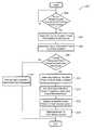
- FIG. 2is a flowchart illustrating an exemplary method for charging a vehicle battery, and may be used with the exemplary system shown in FIG. 1 .
- the system and method described belowmay be used to charge a plug-in electric vehicle with an external power source, and may do so even when the overall power requested by the plug-in electric vehicle exceeds the overall power available from the external power source.
- the system and methoddetermine the overall power requested by one or more high voltage vehicle systems, and then compare that to the overall available power from the external power source. If the overall requested power exceeds the overall available power, then the power from the external power source is allocated or apportioned to the different high voltage vehicle systems according to a process or technique that may consider factors like predetermined priorities and current vehicle conditions, for example.
- plug-in electric vehiclebroadly includes any type of vehicle that has an energy storage device that assists with vehicle propulsion, such as a rechargeable battery pack, and can be connected to and charged by an external power source.
- plug-in electric vehiclesinclude, but are certainly not limited to, plug-in hybrid electric vehicles (PHEV) which include both an internal combustion engine and an electric motor in the vehicle powertrain, as well as battery electric vehicles (BEVs) which solely rely upon an electric motor for vehicle propulsion.
- PHEVplug-in hybrid electric vehicles
- BEVsbattery electric vehicles
- battery charging system 10includes an external power source 12 , a battery charger 14 , a number of high voltage vehicle systems (e.g., a high voltage battery unit 20 , a battery thermal system 22 , a cabin thermal system 24 , an accessory power module 26 , and one or more additional high voltage systems 28 ), and a battery charging control module 30 .
- a circuit, bus or other suitable high voltage connection 40may be used to provide electrical power from battery charger 14 to the different vehicle systems 20 - 28
- a circuit, bus or other suitable low voltage connection 42may be used to exchange information, data, messages, or otherwise communicate between the various systems and devices. All of the devices and systems shown in FIG. 1 , with the exception of external power source 12 , may be fixedly mounted and located on the plug-in electric vehicle.
- External power source 12provides battery charging system 10 with electrical power over a power coupling 50 , and may be one of a number of different power supply types known in the art.
- external power source 12can be a standard AC power outlet that provides electricity at 110V, 220V or any other suitable voltage level, or it can be a portable generator such as the type that runs on natural gas, propane, gasoline, diesel, or the like.
- external power source 12is a renewable power source, such as a remote charging station powered by energy from solar panels, wind turbines, hydroelectric means, biomass, etc.
- External power source 12may be connected to battery charger 14 in one of a variety of different ways, including via conductive connections (e.g., power coupling 50 ), inductive connections, as well as other connections known in the art.
- power coupling 50is a specialized vehicle power coupling (such as those described in specifications SAE J-1772 and J-1773), and includes a first end for connecting to a standard AC power outlet and a second end for connecting to the plug-in electric vehicle. This enables a user to easily connect and disconnect the plug-in electric vehicle from a common AC power outlet, such as those found in most homes and garages. Skilled artisans will appreciate that the system and method described herein are not limited to any particular external power source, as a number of different power source types could be used.
- Battery charger 14is connected to both external power source 12 and high voltage circuit 40 , and provides electrical power to one or more of the vehicle systems 20 - 28 according to charging control signals from battery charging control module 30 .
- battery charger 14is a programmable charger that is mounted in the plug-in electric vehicle and includes a transformer 52 , a rectifier 54 , a switching power supply 56 , a filter network 58 , a cooling unit 60 , one or more sensors 62 , a control unit 64 , and any other suitable components known in the art.
- transformer 52steps-up and/or steps-down the input voltage from external power source 12 to a different and, in some cases, programmable output voltage.
- Rectifier 54rectifies the AC signal into a DC signal and may include a half-wave, full-wave or other type of known rectifying arrangement.
- Switching power supply 56takes the rectified signal and, according to one embodiment, rapidly switches a power transistor or other switch between saturation (‘on’) and cutoff (‘off’) according to a variable duty cycle whose average corresponds to the desired output voltage. In this way, switching power supply 56 may control the amount of current, and hence the output power, that is provided by battery charger 14 to high voltage circuit 40 .
- Filter network 58may include any combination of electrical components that can be used to filter, process, or otherwise condition the output voltage before providing it to high voltage circuit 40 .
- Cooling unit 60also an optional component, may use any combination of fans, water jackets, heat sinks, or other suitable cooling means to reduce the temperature of battery charger 14 during charging.
- battery charger 14could have multiple power outputs including a high voltage output 66 connected to high voltage circuit 40 and a lower voltage output (not shown) connected to a low voltage circuit that includes a low voltage battery, for example.
- Battery charger sensors 62may include any combination of hardware and/or software components capable of monitoring battery charger conditions such as charger temperature, charger input voltage (typically an AC voltage), charger output voltage (typically a DC Voltage), charger current, etc. Depending on the particular embodiment, these sensors may be integrated within battery charger 14 , they may be external sensors located outside of the battery charger, or they may be provided according to some other known arrangement. A charger temperature sensor may sense the temperature of one or more components within battery charger 14 , including the temperature of the least efficient component; that is, the component of the battery charger that exhibits the most heat. Battery charger sensors 62 may be coupled directly to control unit 64 , or they could be coupled to any number of other devices, components, modules, etc., including some located outside of battery charger 14 , like battery charging control module 30 .
- Control unit 64may include any variety of electronic processing devices, memory devices, input/output (I/O) devices, and other known components, and may perform various control and/or communication related functions. For example, control unit 64 could receive sensor signals from the various battery charger sensors 62 , package the sensor signals into an appropriate sensor message, and send the sensor message to battery charging control module 30 over low voltage bus 42 , which may be a CAN bus, a system management bus (SMBus), a proprietary communication link, or any other communication means known to those skilled in the art. In another capacity, control unit 64 may receive charging control signals or other instructions from battery charging control module 30 or some other device, interpret the instructions, and execute the instructions by correspondingly controlling devices within battery charger 14 .
- I/Oinput/output
- control unit 64can use the charging control signal to manipulate the pulse width modulated (PWM) duty-cycle of switching power supply 56 . This, in turn, causes switching power supply 56 to alter the amount of current, and ultimately the amount of output power, that is provided by battery charger 14 to one or more of the vehicle systems 20 - 28 .
- PWMpulse width modulated
- High voltage battery unit 20provides the plug-in electric vehicle with electrical power and, depending on the particular embodiment, may be the primary electrical power source for the vehicle or may be used in conjunction with another power source for power supplementation purposes, to cite two examples.
- Battery pack 70may include a collection of identical or individual battery cells connected in series, parallel, or a combination of both in order to deliver a desired voltage, amperage, capacity, power density, and/or other performance characteristics.
- it is desirable to provide high power and energy densitieswhich has led to the development and use of many types of batteries including chemical, non-chemical, and others.
- Suitable battery typesinclude all types of lithium-ion (e.g., lithium iron phosphate, lithium nickel manganese cobalt, lithium iron sulfide, lithium polymer, etc.), lead-acid, advanced lead-acid, nickel metal hydride (NiMH), nickel cadmium (NiCd), zinc bromide, sodium nickel chloride (NaNiCl), zinc air, vanadium redox, and others.
- the battery pack 70may provide approximately 40-600V, depending on its particular design and application. For example, a heavy truck using a two-mode hybrid system may require a high voltage battery pack capable of providing about 350V, where a lighter vehicle may only need about 200V.
- the battery charging system 10may be part of a belt-alternator-starter (BAS) or BAS-plus type system and thus only require a battery pack that provides about 40-110V.
- battery pack 70should be designed to withstand repeated charge and discharge cycles and to receive electrical energy from external power source 12 . Skilled artisans will appreciate that the system and method described herein are not limited to any one particular type of battery or battery arrangement, as a number of different battery types could be employed.
- Battery sensors 72may include any combination of hardware and/or software components capable of monitoring battery conditions such as battery temperature, battery voltage, battery current, battery state of charge (SOC), battery state of health (SOH), etc. These sensors may be integrated within high voltage battery unit 20 (e.g., an intelligent or smart battery), they may be external sensors located outside of the battery unit, or they may be provided according to some other known arrangement.
- the battery temperature sensorsmay monitor and determine the battery temperature on a cell-by-cell basis, as an average or collective temperature of a block of cells or a region of the battery unit, as the average or collective temperature of the entire battery unit, or according to some other temperature determining method known in the art.
- Measuring battery temperature on an individual cell basismay be beneficial if, for example, the middle cells exhibit different temperatures than the edge or boundary cells of battery pack 70 .
- the same principal of determining battery temperature on a cell-by-cell, collective or other basisalso applies to battery voltage, battery current, battery SOC, battery SOH, etc.
- Output from battery sensors 72may be provided to control unit 74 , battery charging control module 30 , or some other appropriate device.
- Control unit 74may include any variety of electronic processing devices, memory devices, input/output (I/O) devices, and other known components, and may perform various control and/or communication related functions. For example, control unit 74 could receive sensor signals from the various battery sensors 72 , package the sensor signals into an appropriate sensor message, and send the sensor message to battery charging control module 30 over low voltage bus 42 . It is possible for control unit 74 to gather battery sensor readings and store them in local memory so that a comprehensive sensor message can be provided to battery charger control module 30 at a later time, or the sensor readings can be forwarded to module 30 or some other destination as soon as they arrive at control unit 74 , to cite a few possibilities.
- I/Oinput/output
- control unit 74can process or analyze the sensor readings itself.
- control unit 74can store pertinent battery characteristics and background information pertaining to the battery's cell chemistry, cell capacity, upper and lower battery voltage limits, battery current limits, battery temperature limits, temperature profiles, battery impedance, number or history of charge/discharge events, etc.
- Battery thermal system 22is thermally coupled to battery charger 14 and/or high voltage battery unit 20 so that it can manage, control or otherwise manipulate aspects of the environment that can affect the performance of those devices.
- battery thermal system 22may include a cooling and/or heating device that can lower or raise the temperature of high voltage battery unit 20 .
- Skilled artisanswill appreciate that the charging and discharging performance, the life span, as well as other characteristics of a battery pack may be influenced by temperature. When starting a vehicle in an extremely cold environment, for example, battery thermal system 22 can use a heating device to warm up battery pack 70 to a temperature that is better suited for charging, discharging, etc.
- battery thermal system 22may include a cooling device, like a fan, to reduce the temperature of battery pack 70 during charging, discharging, etc. so that it is maintained at a lower and more desirable temperature.
- battery thermal system 22includes one or more heating/cooling devices 80 , sensors 82 , and a control unit 84 .
- a suitable heating/cooling device 80include: fans, water jackets, air passages, heat sinks, thermoelectric coolers (e.g., Peltier devices), internal resistive heating, condensers, or some combination thereof.
- the heating/cooling device 80may include passive devices (e.g., devices that rely on the non-heated and non-cooled ambient environment to manipulate temperature), active devices (e.g., devices that actively add or remove heat from the system to manipulate temperature), or both.
- the sensors 82 and control unit 84 that are included within battery thermal system 22may be similar to those included within battery charger 14 and/or high voltage battery unit 20 ; thus, the previous description of those components applies here as well. It is also possible for battery thermal system 22 to rely on the sensor readings and other information from sensors 62 and/or 72 , in which case sensors 82 may be omitted.
- Battery thermal system 22may include components that are thermally coupled with battery charger 14 ; this could be in addition to or in lieu of those that are thermally coupled to high voltage battery unit 20 .
- battery charger 14is schematically shown having its own cooling unit 60 , it is possible for the cooling and/or heating devices that regulate the temperature of the battery charger to be included within battery thermal system 22 . It therefore does not matter whether the cooling and/or heating devices are specifically bundled within battery charger 14 , high voltage battery unit 20 , or battery thermal system 22 ; they will henceforth be treated as if they are a part of battery thermal system 22 , whether or not they physically reside there.
- battery thermal system 22is connected to high voltage circuit 40 so that it can receive high voltage electrical power from battery charger 14 , and is connected to low voltage bus 42 so that it can send messages and exchange information with other devices in the system, like battery charging control module 30 .
- Other connections and arrangementsare possible, as this is only one potential.
- Cabin thermal system 24is thermally coupled with the cabin or interior of the plug-in electric vehicle so that it can manage, control or otherwise manipulate aspects of the environment within that space.
- cabin thermal system 24may include the vehicle's heating, ventilation and air conditioning (HVAC) system which manipulates the environmental conditions—thermal and otherwise—within the vehicle cabin.
- HVACheating, ventilation and air conditioning
- cabin thermal system 24includes one or more heating/cooling devices 90 , sensors 92 , and a control unit 94 .
- Heating/cooling devices 90include any device or component that is capable of influencing or affecting the environment within the vehicle cabin. This may include, for example, heaters, air conditioners, seat heaters, steering wheel heaters, fans, etc.
- cabin thermal system 24may be similar to those included within battery charger 14 and/or high voltage battery unit 20 ; thus, the previous description of those components applies here as well.
- cabin thermal system 24is connected to high voltage circuit 40 so that it can receive high voltage electrical power from battery charger 14 , and is connected to low voltage bus 42 so that it can send messages and exchange information with other devices in the system, like battery charging control module 30 .
- Other connections and arrangementsare possible, as this is only one potential.
- Accessory power module (APM) 26couples or connects high and low voltage circuits within the vehicle, and may perform a number of different functions in that capacity.
- APM 26may include a step-down transformer and other electrical components for stepping-down the voltage on the high voltage circuit 40 (e.g., a voltage of 350V) to the lower level of low voltage circuit 44 (e.g., a voltage of 12V or 42V).
- APM 26can provide a steady and dependable source of low voltage DC power to the components of low voltage circuit 44 ; this includes, for example, accessories 96 (e.g., a radio receiver, DVD player, television, telematics unit and/or other infotainment devices, as well as vehicle interior and exterior lights, auxiliary power plugs, power doors and windows, etc.), low voltage battery 98 (e.g., a conventional 12V lead-acid battery), various modules and control units (e.g., battery charging control module 30 and control units 64 , 74 , 84 , 94 that require low voltage DC power for operation), as well as any other component, device, system, etc. that requires low voltage power.
- accessories 96e.g., a radio receiver, DVD player, television, telematics unit and/or other infotainment devices, as well as vehicle interior and exterior lights, auxiliary power plugs, power doors and windows, etc.
- low voltage battery 98e.g., a conventional 12V lead-acid
- APM 26includes one or more electrical devices 100 (e.g., a transformer for stepping down power from high voltage circuit 40 to low voltage circuit 44 ), sensors 102 , and a control unit 104 .
- Electrical device 100is not limited to a transformer, as it may include any electrical device used in coupling or providing power between high and low voltage circuits 40 and 44 .
- the sensors 102 and control unit 104 that are included within APM 26may be similar to those included within battery charger 14 and/or high voltage battery unit 20 ; thus, the previous description of those components applies here as well. It is also possible for APM 26 to be combined or otherwise integrated with other components in the plug-in electric vehicle.
- Additional high voltage system(s) 28broadly includes all other components, devices, modules, systems, etc. in the vehicle that are connected to high voltage circuit 40 and require high voltage electrical power for operation.
- Some examples of potential additional high voltage systemsinclude ride height systems, engine block heaters, hydraulic pumps, vacuum pumps, active engine mounts, electric power steering systems, electric winches, etc.
- high voltage and low voltageare not limited to any particular voltage rating. Instead, these terms are relative in that high voltage circuit 40 (the circuit within the plug-in electric vehicle that is connected to, among other items, the battery unit used for vehicle propulsion) generally has a higher voltage than low voltage circuit 44 (the circuit that provides power to low voltage accessories 96 and may be connected to a 12V battery or the like). Therefore, while some preferred voltage ratings and ranges are provided above for purposes of illustration, the system and method described herein are not limited to such embodiments.
- Battery charging control module 30monitors various conditions throughout the plug-in electric vehicle and uses these conditions to control certain aspects of the charging process.
- battery charging control module 30may be a stand-alone vehicle electronic module, it may incorporated or included within another vehicle electronic module (e.g., a hybrid control module), or it may be part of a larger network or system (e.g., a battery management system (BMS), a vehicle energy management system, etc.), to name a few possibilities.
- Battery charging control module 30may perform a number of functions pertaining to battery charging system 10 ; these could include, for example, battery charging, power allocation, cell protection, charge control, demand management, SOC and SOH determination, cell balancing, history logging, communications, etc.
- Battery charging control module 30may include any variety of electronic processing devices, memory devices, input/output (I/O) devices, and other known components, and may perform various control and/or communication related functions.
- the battery charging control module 30can be electronically connected to other vehicle devices and modules via low voltage bus 42 or some other suitable vehicle communications network, and can interact with them when required.
- battery charging control module 30includes an electronic processing device 110 (e.g., a microprocessor, a microcontroller, an application specific integrated circuit (ASIC), etc.) that executes instructions for software, firmware, programs, algorithms, scripts, etc. that are stored in an electronic memory device 112 and may govern the battery charging processes and methods described herein.
- ASICapplication specific integrated circuit
- Battery charging control module 30could also store or maintain look up tables or other data structures, various sensor readings (e.g., sensor readings from sensors 62 , 72 , 82 , 92 , 102 , etc.), and predetermined values used by one or more algorithms, for example. These are, of course, only some of the possible functions and capabilities of battery charging control module 30 , as other embodiments could also be used.
- battery charging system 10 shown in FIG. 1is only a general and schematic illustration of one potential system.
- the system and method described hereinmay be used with any number of plug-in electric vehicles and is not limited to the specific embodiments shown here.
- battery charging system 10could include a combination of vehicle systems that differs from that shown in FIG. 1 ; the combination could include more, less or different vehicle systems than the exemplary devices 20 - 28 .
- FIG. 2there is shown an exemplary method 200 for allocating or distributing electrical power during a charging process for a plug-in electric vehicle.
- the methodmay use various readings, conditions, information, comparisons, calculations, etc. to allocate power among the vehicle systems 20 - 28 in an optimum fashion.
- the system and methoddetermine the overall power requested by vehicle systems 20 - 28 , and then compare that to the overall available power from external power source 12 . If the overall requested power exceeds the overall available power, then the power from external power source 12 is allocated or apportioned to the different vehicle systems 20 - 28 in an optimum fashion based on the process or technique described below. A number of different factors and considerations may influence what constitutes an “optimum fashion”.
- an optimum processmay strive to charge high voltage battery unit 20 in the shortest time possible. In such a case, a greater portion of the overall available power may be diverted to high voltage battery unit 20 as opposed to the other vehicle systems 22 - 28 .
- an optimum processmay involve charging high voltage battery unit 20 in a manner that best extends its battery life (e.g., slow charging the battery). This scenario may involve providing high voltage battery 20 with a lesser portion of the overall available power while simultaneously sending power to battery thermal system 22 so that the battery temperature can be maintained in a preferred temperature range.
- an optimum fashionmay strive to first satisfy the immediate needs of the user over charging the battery; like powering the vehicle HVAC system when the user is in the vehicle during charging on an extremely hot/cold day.
- predetermined prioritiese.g., priorities set during the design and/or manufacturing phase
- An engineering teammay determine, for example, that battery life is the most important factor and establish this as a predetermined priority.
- Current vehicle conditionse.g., the current temperature and/or SOC of battery pack 70 , etc.
- exemplary method 200may take into account predetermined priorities, current vehicle conditions and/or other factors when allocating or distributing power to the various vehicle systems 20 - 28 .
- the methoddetermines if the plug-in electric vehicle is connected to external power source 12 .
- This stepmay be performed in one of any number of different ways and may sense one or more conditions pertaining to external power source 12 and/or the charging process in order to do so. For instance, if sensors 62 in battery charger 14 detect a current or voltage that exceeds a certain threshold, this step may conclude that external power source 12 is properly connected to battery charger 14 and is available to provide power. Other techniques for determining a connection with external power source 12 may also be used.
- Step 204determines the overall available power to the plug-in electric vehicle from external power source 12 .
- a current readingis obtained from power coupling 50 and a voltage reading is obtained from the same power coupling and/or sensors 62 ; these two readings are then multiplied together to estimate the overall available power from external power source 12 .
- Power couplingsthat conform to the SAE J-1772 and J-1773 standards are generally capable of providing this type of current reading.
- steps 202 and 204may be combined into a single step that determines both the presence and amount of overall available power. It is possible for these readings to be provided to battery charging control module 30 , control unit 64 , or to some other device for processing.
- power coupling 50 and sensors 62may include any electrodynamic, electronic, digital, analog or other devices such as power meters, energy meters, watt meters, ammeters, voltmeters, etc. Other techniques for determining the overall available power from external power source 12 may also be used.
- step 206determines the overall power requested by one or more vehicle systems 20 - 28 from external power source 12 .
- required powergenerally refers to the minimum amount of power needed for a particular high voltage vehicle system 20 - 28 to successfully function or operate. In one embodiment, the required power may be determined through lookup or empirical tables established at a design and/or manufacturing phase.
- quested powergenerally refers to the preferable or desired power needed by a particular high voltage vehicle system 20 - 28 in order to achieve the tasks that have been requested of them. The required power is generally less than or equal to the requested power.
- the required powermay pertain to the minimum amount of power required to successfully operate cabin thermal system 24 at its lowest setting; the requested power may pertain to the amount of power required to operate cabin thermal system 24 at the high setting requested by the user.
- step 206determines the overall requested power by summing together the individual requested power for each of the vehicle systems 20 - 28 .
- Thisprovides the method with the overall amount of power being requested by all of the vehicle systems 20 - 28 together and provides it with the amount of power being requested by each individual system. For example, if high voltage battery unit 20 asks for 1,500 W for charging the battery, battery thermal system 22 asks for 1,000 W for maintaining the high voltage battery unit at a certain temperature, cabin thermal system 24 asks for 750 W for powering the vehicle's HVAC system, APM 26 asks for 250 W for operating one or more low voltage devices such as the various control units, and no additional high voltage vehicle system 28 requests power, then the overall requested power is 3,500 W.
- These requestsmay be in the form of electronic messages sent from the respective control units of vehicle systems 20 - 28 to battery charging control module 30 over low voltage bus 42 , or some other form.
- a default valuemay be used to determine the amount of power being requested by a certain high voltage vehicle system; for example, it may be assumed that APM 26 requires 250 W of power instead of the APM actually sending a request for such power.
- step 206could determine the overall requested power, as other techniques could be used instead.
- step 208determines if the overall requested power exceeds the overall available power.
- battery charging control module 30simply compares the overall available power to the overall requested power to make this determination. If the overall requested power does not exceed the overall available power, then the method may proceed to step 210 and vehicle systems 20 - 28 are simply provided with the power that they requested. In this scenario, external power source 12 has enough power to fully satisfy all of the requests, including charging high voltage battery unit 20 , and thus allocating or apportioning the power is not necessary. If the overall requested power does exceed the overall available power, then the method continues with step 212 .
- the overall requested poweris 3,500 W; if the overall available power is only 1,500 W, then the method would proceed to step 212 .
- Step 212determines an individual modified power for each of the vehicle systems 20 - 28 that are asking for power. Step 212 may use an allocation or apportionment process (also referred to as costing) to determine the individual modified power values for the various vehicle systems. Since there is not enough available power from external power source 12 to meet all of the power demands, the amount of power requested by each high voltage vehicle system 20 - 28 has to be modified in order to accommodate the limited power resources.
- an allocation or apportionment processalso referred to as costing
- step 212uses a multistep process that includes: identifying those vehicle systems 20 - 28 that are turned ‘on’ and are in need of power (some vehicle systems may be turned ‘off’ or not requesting any power); assigning a first weighted value to the vehicle systems 20 - 28 that are requesting power, where the first weighted value is influenced by one or more predetermined priorities; and assigning a second weighted value to those vehicle systems, where the second weighted value is influenced by one or more current vehicle conditions. These and other factors may be used to calculate an individual modified power for each of the vehicle systems 20 - 28 , which in turn can affect the overall allocation or distribution of power.
- This multistep processis illustrated through the following example.
- each of the vehicle systems 20 - 28is queried to determine if they are ‘on’ and how much power they need.
- the control unit in each of the vehicle systems 20 - 28sends an electronic message to battery charging control module 30 that includes the individual requested power (e.g., high voltage battery unit 20 requests 1,500 W, battery thermal system 22 requests 1,000 W, cabin thermal system 24 requests 750 W, APM 26 requests 250 W, and system 28 requests 0 W).
- battery charging control module 30It is also possible for battery charging control module 30 to use predetermined values and assume that a particular system, like APM 26 , needs a certain amount of power instead of actually querying it.
- a first weighted valueis assigned to each of the vehicle systems 20 - 26 (a process sometimes referred to as costing), where the first weighted value is influenced by one or more of the predetermined priorities.
- the first weighted value for high voltage battery unit 20is ‘5’ (corresponds to 50% of the available power)
- the weighted value for battery thermal system 22is ‘3’ (corresponds to 30%)
- the weighted values for cabin thermal system 24 and APM 26are ‘1’ (corresponds to 10%).
- the first weighted values assigned hereare not impacted by current vehicle conditions inside or outside of the vehicle, but instead are influenced by predetermined priorities, such as those described above. It should be appreciated that the predetermined priorities could be programmable; that is, they could be changed or adjusted over time instead of being statically set during design and/or manufacture, or they could be static.
- a second weighted valueis assigned to each of the vehicle systems 20 - 26 , where the second weighted value is influenced by one or more current vehicle conditions.
- the second weighted valueis intended to address situations where the current conditions occurring at or around the vehicle require modification to the predetermined priorities, which are more directed to an ‘ideal case scenario’. For instance, in the current example, the following look-up table could be used to evaluate the SOC of battery pack 70 and assign a second weighted value accordingly.
- look-up tablescould be used for this step and, in one embodiment, a separate look-up table is used for each of the current vehicle conditions or parameters that is being monitored.
- Table IIcould be used to evaluate the temperature of battery pack 70 and assign a second weighted value accordingly.
- the preferred temperature range for exemplary battery pack 70is between 10-20° C.; in this temperature range there is not a great need to supply battery thermal system 22 with power because the battery unit is already at a desirable temperature. As the battery temperature moves away from this preferred range, either hotter or colder, the second weighted value goes up because battery thermal system 22 needs more power to maintain the battery at its desired thermal condition. In the example above, battery pack 70 has a temperature of 35° C. which would translate into a second weighted value of ‘5’.
- the actual values usedcould vary significantly from those provided above;
- the current vehicle conditions usedcould be absolute values (e.g., actual temperatures) or they could be relative values (e.g., temperature differences, temperature ratios, rates of temperature change, etc.);
- the weighted valuescould be static values set at design and/or manufacturing or they could be dynamic values occasionally updated and or changed (e.g., updated via wireless downloads, updated at the vehicle through fuzzy logic, a neural network, etc.); the weighted values do not have to be integers, but instead could be fractions, percentages or any other numerical value;
- the entity used to correlate a current vehicle condition to a weighted valuecould be something other than a two-dimensional look-up table (e.g., it could be a three- or four-dimensional look-up table where each high voltage vehicle system 20 - 28 is assigned a single second weighted value based on two or three current vehicle conditions or parameters,
- step 212can determine the individual modified power for each high voltage vehicle system 20 - 28 .
- a 1 st individual modified poweris determined for high voltage battery unit 20
- a 2 nd individual modified poweris determined for battery thermal system 22
- a 3 rd individual modified poweris determined for cabin thermal system 24
- a 4 th individual modified poweris determined for APM 26
- an N th individual modified poweris determined for the last vehicle system.
- battery thermal system 22is to receive the most amount of power among the various vehicle systems 20 - 28 . This is true even though the predetermined priorities have high voltage battery unit 20 receiving 50% of the available power, while battery thermal system 22 is only to receive 30% of the available power. This is due to the second weighted value. Because high voltage battery unit 20 is already almost fully charged (SOC of 80%), it does not require as much power for charging; however, the battery temperature is 35° C. which is outside of the desired temperature range by a fair amount. Thus, the percentage or portion of the overall available power delivered to battery thermal system 22 in order to keep the battery cool is increased; this is an example of current vehicle conditions affecting the allocation of power among the vehicle systems 20 - 28 .
- Equation 1an additional element of ‘0’ and ‘1’ could be added to Equation 1, where a ‘1’ is used for vehicle systems that are turned ‘on’ and a ‘0’ is used for vehicle systems that are turned ‘off’ or not requesting power. If the vehicle system is turned off, then this additional element would make the entire product ‘0’. Also, the first and second weighted values could be combined into a single weighted value; or additional weighted values and/or other factors could be used in the calculations of step 212 .
- step 214adds together the individual modified power for each of the plurality of vehicle systems 20 - 28 to determine an overall modified power, as shown in equation 2.
- Overall Modified Power(1 st Individual Modified Power+2 nd Individual Modified Power+ . . . +N th Individual Modified Power) (Equation 2)
- Equations 1 and 2may be performed by battery charging control module 30 , by control units 74 , 84 , 94 , 104 , or both.
- Step 216then uses the individual modified power for each of the vehicle systems 20 - 28 (determined in step 212 ) and the overall modified power (determined in step 214 ) to determine how much power each of the vehicle systems is to receive from the external power source. Put differently, now that the modified or weighted amount of power for each high voltage vehicle system 20 - 28 has been calculated, step 216 can determine the percentage or portion of the overall available power that is to be allocated to each vehicle system. In one embodiment, each individual modified power is divided by the overall modified power to obtain a modified power portion, as shown in Equation 3.
- Modified Power PortionIndividual Modified Power/Overall Modified Power (Equation 3)
- Modified Power AmountModified Power Portion*Overall Available Power (Equation 4)
- the actual amount of power distributed to vehicle systems 20 - 28is less than the amounts that they requested (e.g., high voltage battery unit 20 requested 1,500 W but is only provided with 375 W; battery thermal system 22 requested 1,000 W but is only provided with 562.5 W, etc.).
- a vehicle systemit is possible for a vehicle system to be allocated more energy than it requested; such as the case with APM 26 in the example above.
- There are a number of techniques that could be used to address such a situationincluding one where the individual requested power for that vehicle system is simply subtracted from the overall available power right off of the top so that the new overall available power is less by that amount.
- 250 W(individual requested power for APM 26 ) could be subtracted from the overall available power of 1,500 W, which results in a new overall available power of 1,250 W.
- method 200may assume that the APM is to receive the full 250 W of power that were requested and treat all subsequent calculations involving the overall available power as being less that amount (i.e., overall available power now equals 1,250 W).
- This techniqueis optional and may be used with any number of other vehicle systems as well, particularly those where the individual requested power is an assumed or predetermined amount.
- the method, steps, techniques, procedures, etc. described abovemay be performed or executed by any number of different devices, including battery charging control module 30 , control units 64 , 74 , 84 , 94 , 104 , or other devices such as vehicle integration control module, battery pack/inverter control module, domain module, body control module, etc.
- the exemplary embodiment provided aboveis only an illustrative example, as the present system and method may use any number of different combinations and sequences of steps, including those having less, more or different steps than described in this embodiment.
- the modified power amountscan be further adjusted to accommodate for losses during power distribution, power fluctuations, or other real life scenarios.
- Step 218distributes the overall available power to the various vehicle systems 20 - 28 according to the allocation or apportionment previously determined.
- thismay be carried out.
- Two examplesinclude passive allocation where the overall available power is put onto high voltage circuit 40 so that each vehicle system 20 - 28 can passively draw or take its allocated amount, and active allocation where battery charger 14 or some other device actively distributes the allocated amounts to the different vehicle systems.
- battery charger 14provides high voltage circuit 40 with the entire amount of overall available power, from which systems 20 - 28 draw their apportioned amounts of power.
- the specific amounts of power drawnmay be dictated by control messages sent from battery charging control module 30 to the individual control units 74 , 84 , 94 , 104 of the vehicle systems, for example.
- battery charger 14receives a control message from battery charging control module 30 instructing it on how to allocate or distribute the power to the different vehicle systems 20 - 28 .
- battery charger 14actively allocates the specific power to the vehicle systems, as opposed to the vehicle systems drawing or taking their allocations, as in the passive example.
- the switching power supply 56 in battery charger 14may be used with this process.
- battery charger 14could provide all of the overall available power to high voltage battery unit 20 first, from which the power could be properly allocated to the other vehicle systems.
- Method 200could continue to loop or cycle so long as the plug-in electric vehicle was still being charged.
- exemplary method 200may be altered; method 200 may be used in a regenerative charging process as opposed to being used only with an external power source 12 ; method 200 may include some type of manual user override in the event that a user wanted to override the allocation or distribution determined by the method, etc. All such other embodiments, changes, and modifications are intended to come within the scope of the appended claims.
- the terms “for example,” “for instance,” “such as,” and “like,” and the verbs “comprising,” “having,” “including,” and their other verb forms, when used in conjunction with a listing of one or more components or other items,are each to be construed as open-ended, meaning that that the listing is not to be considered as excluding other, additional components or items.
- Other termsare to be construed using their broadest reasonable meaning unless they are used in a context that requires a different interpretation.
Landscapes
- Engineering & Computer Science (AREA)
- Power Engineering (AREA)
- Transportation (AREA)
- Mechanical Engineering (AREA)
- Life Sciences & Earth Sciences (AREA)
- Sustainable Development (AREA)
- Sustainable Energy (AREA)
- Charge And Discharge Circuits For Batteries Or The Like (AREA)
- Electric Propulsion And Braking For Vehicles (AREA)
Abstract
Description
| TABLE I | |||
| Battery Pack SOC | Second Weighted Value | ||
| 90-100% | 1 | ||
| 70-90% | 2 | ||
| 50-70% | 5 | ||
| 0-50% | 10 | ||
| TABLE II | |||
| Battery Pack Temp | Second Weighted Value | ||
| <0° | C. | 10 | ||
| 0-10° | C. | 5 | ||
| 10-20° | C. | 1 | ||
| 20-30° | C. | 3 | ||
| 30-40° | C. | 5 | ||
| >40° | C. | 10 | ||
Individual Modified Power=First Weighted Value*Second Weighted Value (Equation 1)
where the first weighted value is influenced by one or more predetermined priorities, and the second weighted value is influenced by one or more current vehicle conditions. A 1stindividual modified power is determined for high
1stIndividual Modified Power (High Voltage Battery Unit)=5*2=10
2ndIndividual Modified Power (Battery Thermal System)=3*5=15
3rdIndividual Modified Power (Cabin Thermal System)=1*5=5
4thIndividual Modified Power (APM)=1*10=10
Overall Modified Power=(1stIndividual Modified Power+2ndIndividual Modified Power+ . . . +NthIndividual Modified Power) (Equation 2)
Depending on the particular embodiment, Equations 1 and 2 may be performed by battery charging
Overall Modified Power=10+15+5+10=40
Modified Power Portion=Individual Modified Power/Overall Modified Power (Equation 3)
In the example used above, Equation 3 is calculated as follows:
1stModified Power Portion=10/40=0.250
2ndModified Power Portion=15/40=0.375
3rdModified Power Portion=5/40=0.125
4thModified Power Portion=10/40=0.250
Modified Power Amount=Modified Power Portion*Overall Available Power (Equation 4)
In the example used above, Equation 4 is calculated as follows:
1stModified Power Amount=0.250*1,500 W=375 W
2ndModified Power Amount=0.375*1,500 W=562.5 W
3rdModified Power Amount=0.125*1,500 W=187.5 W
4thModified Power Amount=0.250*1,500 W=375 W
Claims (21)
Priority Applications (2)
| Application Number | Priority Date | Filing Date | Title |
|---|---|---|---|
| US12/544,585US8760115B2 (en) | 2009-08-20 | 2009-08-20 | Method for charging a plug-in electric vehicle |
| DE102010034105ADE102010034105A1 (en) | 2009-08-20 | 2010-08-12 | Method for charging a plug-in electric vehicle |
Applications Claiming Priority (1)
| Application Number | Priority Date | Filing Date | Title |
|---|---|---|---|
| US12/544,585US8760115B2 (en) | 2009-08-20 | 2009-08-20 | Method for charging a plug-in electric vehicle |
Publications (2)
| Publication Number | Publication Date |
|---|---|
| US20110043165A1 US20110043165A1 (en) | 2011-02-24 |
| US8760115B2true US8760115B2 (en) | 2014-06-24 |
Family
ID=43604813
Family Applications (1)
| Application Number | Title | Priority Date | Filing Date |
|---|---|---|---|
| US12/544,585Expired - Fee RelatedUS8760115B2 (en) | 2009-08-20 | 2009-08-20 | Method for charging a plug-in electric vehicle |
Country Status (2)
| Country | Link |
|---|---|
| US (1) | US8760115B2 (en) |
| DE (1) | DE102010034105A1 (en) |
Cited By (41)
| Publication number | Priority date | Publication date | Assignee | Title |
|---|---|---|---|---|
| US20130009599A1 (en)* | 2010-03-23 | 2013-01-10 | Panasonic Corporation | Charging control apparatus, charging system, and charging control method |
| US20140320062A1 (en)* | 2011-11-22 | 2014-10-30 | Panasonic Corporation | Vehicle management system |
| US9114719B1 (en) | 2010-06-02 | 2015-08-25 | Bryan Marc Failing | Increasing vehicle security |
| US20170136903A1 (en)* | 2015-11-13 | 2017-05-18 | NextEv USA, Inc. | Electric vehicle emergency charging system and method of use |
| CN107301266A (en)* | 2017-05-15 | 2017-10-27 | 中山职业技术学院 | A kind of ferric phosphate lithium cell LOC evaluation methods and system |
| US9908421B2 (en)* | 2013-11-06 | 2018-03-06 | Abb Schweiz Ag | Charger for electric vehicles with distributed power converter arbitration |
| CN108174573A (en)* | 2017-12-08 | 2018-06-15 | 安徽泰德电子科技有限公司 | Moped Scooter charger rapid heat radiation device based on semiconductor chilling plate |
| US20190168593A1 (en)* | 2017-12-01 | 2019-06-06 | Subaru Corporation | Onboard charging system |
| US10343539B2 (en)* | 2015-08-31 | 2019-07-09 | Nichicon Corporation | Power supply device for supplying electricity to a load utilizing electric power of a storage-battery-equipped vehicle |
| US10421462B2 (en) | 2015-06-05 | 2019-09-24 | Gogoro Inc. | Systems and methods for vehicle load detection and response |
| US10532663B2 (en) | 2015-11-13 | 2020-01-14 | Nio Usa, Inc. | Electric vehicle overhead charging system and method of use |
| US20200083706A1 (en)* | 2015-07-23 | 2020-03-12 | Briggs & Stratton Corporation | Lithium-ion battery including two power supplies |
| US10632852B2 (en) | 2015-11-13 | 2020-04-28 | Nio Usa, Inc. | Electric vehicle optical charging system and method of use |
| US10870333B2 (en) | 2018-10-31 | 2020-12-22 | Thermo King Corporation | Reconfigurable utility power input with passive voltage booster |
| US10875497B2 (en) | 2018-10-31 | 2020-12-29 | Thermo King Corporation | Drive off protection system and method for preventing drive off |
| US10926610B2 (en) | 2018-10-31 | 2021-02-23 | Thermo King Corporation | Methods and systems for controlling a mild hybrid system that powers a transport climate control system |
| US10967750B2 (en)* | 2016-05-26 | 2021-04-06 | Hyundai Motor Company | System and method for charging plug-in hybrid vehicle |
| US10985511B2 (en) | 2019-09-09 | 2021-04-20 | Thermo King Corporation | Optimized power cord for transferring power to a transport climate control system |
| US11022451B2 (en) | 2018-11-01 | 2021-06-01 | Thermo King Corporation | Methods and systems for generation and utilization of supplemental stored energy for use in transport climate control |
| US11034213B2 (en) | 2018-09-29 | 2021-06-15 | Thermo King Corporation | Methods and systems for monitoring and displaying energy use and energy cost of a transport vehicle climate control system or a fleet of transport vehicle climate control systems |
| US11059352B2 (en) | 2018-10-31 | 2021-07-13 | Thermo King Corporation | Methods and systems for augmenting a vehicle powered transport climate control system |
| US11072321B2 (en) | 2018-12-31 | 2021-07-27 | Thermo King Corporation | Systems and methods for smart load shedding of a transport vehicle while in transit |
| US11135894B2 (en) | 2019-09-09 | 2021-10-05 | Thermo King Corporation | System and method for managing power and efficiently sourcing a variable voltage for a transport climate control system |
| US11192451B2 (en) | 2018-09-19 | 2021-12-07 | Thermo King Corporation | Methods and systems for energy management of a transport climate control system |
| US11203262B2 (en) | 2019-09-09 | 2021-12-21 | Thermo King Corporation | Transport climate control system with an accessory power distribution unit for managing transport climate control loads |
| US11214118B2 (en) | 2019-09-09 | 2022-01-04 | Thermo King Corporation | Demand-side power distribution management for a plurality of transport climate control systems |
| US11260723B2 (en) | 2018-09-19 | 2022-03-01 | Thermo King Corporation | Methods and systems for power and load management of a transport climate control system |
| US11273718B2 (en) | 2017-10-13 | 2022-03-15 | dcbel Inc. | Electric vehicle battery charger |
| US11273684B2 (en) | 2018-09-29 | 2022-03-15 | Thermo King Corporation | Methods and systems for autonomous climate control optimization of a transport vehicle |
| US11376922B2 (en) | 2019-09-09 | 2022-07-05 | Thermo King Corporation | Transport climate control system with a self-configuring matrix power converter |
| US11420495B2 (en) | 2019-09-09 | 2022-08-23 | Thermo King Corporation | Interface system for connecting a vehicle and a transport climate control system |
| US11458802B2 (en) | 2019-09-09 | 2022-10-04 | Thermo King Corporation | Optimized power management for a transport climate control energy source |
| US11489431B2 (en) | 2019-12-30 | 2022-11-01 | Thermo King Corporation | Transport climate control system power architecture |
| US20220348102A1 (en)* | 2019-09-26 | 2022-11-03 | Liikennevirta Oy / Virta Ltd | Control of electric vehicle charging |
| US11554638B2 (en) | 2018-12-28 | 2023-01-17 | Thermo King Llc | Methods and systems for preserving autonomous operation of a transport climate control system |
| US11695275B2 (en) | 2019-09-09 | 2023-07-04 | Thermo King Llc | Prioritized power delivery for facilitating transport climate control |
| US11794551B2 (en) | 2019-09-09 | 2023-10-24 | Thermo King Llc | Optimized power distribution to transport climate control systems amongst one or more electric supply equipment stations |
| US11993131B2 (en) | 2018-12-31 | 2024-05-28 | Thermo King Llc | Methods and systems for providing feedback for a transport climate control system |
| US12017505B2 (en) | 2018-12-31 | 2024-06-25 | Thermo King Llc | Methods and systems for providing predictive energy consumption feedback for powering a transport climate control system using external data |
| US12072193B2 (en) | 2018-12-31 | 2024-08-27 | Thermo King Llc | Methods and systems for notifying and mitigating a suboptimal event occurring in a transport climate control system |
| US12097751B2 (en) | 2018-12-31 | 2024-09-24 | Thermo King Llc | Methods and systems for providing predictive energy consumption feedback for powering a transport climate control system |
Families Citing this family (48)
| Publication number | Priority date | Publication date | Assignee | Title |
|---|---|---|---|---|
| US9776519B2 (en)* | 2009-08-18 | 2017-10-03 | Ford Global Technologies, Llc | System and method for controlling electric power in a plug-in vehicle from an external power source |
| JP2011172318A (en)* | 2010-02-16 | 2011-09-01 | Omron Automotive Electronics Co Ltd | Power supply system, and power supply control method |
| JP5258831B2 (en)* | 2010-04-21 | 2013-08-07 | 三菱電機株式会社 | Vehicle charging device |
| WO2011146049A1 (en)* | 2010-05-18 | 2011-11-24 | International Truck Intellectual Property Company, Llc | Detection circuit for open or intermittent motor vehicle battery connection |
| DE102010021028A1 (en)* | 2010-05-19 | 2011-11-24 | Audi Ag | Interaction of thermal management and charging management with external charging |
| DE102010041077A1 (en)* | 2010-09-20 | 2012-03-22 | Robert Bosch Gmbh | System for charging an energy storage and method for operating the charging system |
| TWI423554B (en)* | 2010-12-22 | 2014-01-11 | 財團法人工業技術研究院 | Interactive charging management system and method thereof |
| JP5211268B2 (en)* | 2011-01-19 | 2013-06-12 | 本田技研工業株式会社 | Vehicle charging system |
| JP6012144B2 (en)* | 2011-05-20 | 2016-10-25 | パナソニックエコソリューションズ電路株式会社 | Charge control system |
| DE102011079415B4 (en) | 2011-07-19 | 2018-10-25 | Bayerische Motoren Werke Aktiengesellschaft | Charging an electric vehicle comprising an electric air-conditioning system |
| JP5673474B2 (en)* | 2011-09-27 | 2015-02-18 | 三菱自動車工業株式会社 | Power switching device |
| US8358102B2 (en) | 2011-10-21 | 2013-01-22 | General Electric Company | System, charging device, and method of charging a power storage device |
| US8384359B2 (en) | 2011-10-21 | 2013-02-26 | General Electric Company | System, charging device, and method of charging a power storage device |
| US8332078B2 (en) | 2011-10-21 | 2012-12-11 | General Electric Company | System, charging device, and method of supplying current to a power storage device |
| US9184598B2 (en) | 2011-10-26 | 2015-11-10 | Leggett & Platt Canada Co. | Signal discrimination for wireless key fobs and interacting systems |
| KR101305605B1 (en)* | 2011-11-25 | 2013-09-09 | 엘에스산전 주식회사 | Electric Vehicle Power Supply System |
| NL2008058C2 (en)* | 2011-12-29 | 2013-07-03 | Epyon B V | Method, system and charger for charging a battery of an electric vehicle. |
| US9148027B2 (en) | 2012-07-30 | 2015-09-29 | General Electric Company | Method and system for charging of electric vehicles |
| DE102012020298B4 (en)* | 2012-10-17 | 2016-07-07 | Audi Ag | Method for stabilizing a vehicle electrical system in a motor vehicle |
| FR2998530A1 (en)* | 2012-11-26 | 2014-05-30 | Peugeot Citroen Automobiles Sa | Method for supplying electric power from external energy source to vehicle, involves determining temporal profile of power supply so that sum of levels of power accepted by each equipment is equal to maximum power of external energy source |
| US9484770B2 (en)* | 2012-12-07 | 2016-11-01 | Keme, Inc. | System and method of charging a chemical storage device |
| US9337680B2 (en) | 2013-03-12 | 2016-05-10 | Ford Global Technologies, Llc | Method and system for controlling an electric vehicle while charging |
| CN105189180B (en) | 2013-05-08 | 2018-05-01 | 沃尔沃卡车集团 | Energy management systems for non-rail vehicles |
| DE102013214826A1 (en)* | 2013-07-30 | 2015-02-05 | Bayerische Motoren Werke Aktiengesellschaft | Vehicle with thermoelectric generator |
| CN108189701B (en)* | 2013-08-06 | 2021-10-22 | 睿能创意公司 | Regulation of electric vehicle systems based on electrical energy storage device thermal profiles |
| JP6314442B2 (en)* | 2013-11-21 | 2018-04-25 | スズキ株式会社 | In-vehicle device controller |
| WO2015122196A1 (en)* | 2014-02-17 | 2015-08-20 | 日本電気株式会社 | Occupancy state determination device, delivery system, occupancy state determination method, occupancy state determination program, and delivery terminal |
| DE102014015883B4 (en)* | 2014-10-27 | 2020-12-24 | Audi Ag | Motor vehicle and method for operating at least two electrical consumers on the motor vehicle |
| DE102016207912A1 (en) | 2016-05-09 | 2017-11-09 | Audi Ag | Method for operating a motor vehicle and motor vehicle |
| US20180012197A1 (en) | 2016-07-07 | 2018-01-11 | NextEv USA, Inc. | Battery exchange licensing program based on state of charge of battery pack |
| FR3060888B1 (en) | 2016-12-19 | 2022-08-12 | Electricite De France | IMPROVED CHARGING DEVICE, PARTICULARLY FOR ELECTRIC VEHICLES |
| DE102017212659B4 (en)* | 2017-07-24 | 2024-11-07 | Audi Ag | Method for operating an overall electrical on-board network, control unit and motor vehicle |
| DE102017214645A1 (en)* | 2017-08-22 | 2019-02-28 | Robert Bosch Gmbh | Over Temperature Management |
| DE102017221313B4 (en)* | 2017-11-28 | 2024-06-27 | Audi Ag | Electrical system for a motor vehicle and motor vehicle with such an electrical system |
| CN109228954B (en)* | 2018-09-26 | 2022-06-07 | 曦煦新能源科技(上海)有限公司 | Charging pile energy management method and system and charging pile group system |
| US11642965B2 (en) | 2018-10-11 | 2023-05-09 | Keith Johnson | System and method of powering an external device with a vehicular battery system |
| US11130405B2 (en)* | 2018-10-11 | 2021-09-28 | Keith Johnson | System and method of powering an external device with a vehicular battery system |
| KR102676719B1 (en)* | 2018-12-11 | 2024-06-18 | 현대자동차주식회사 | System of controlling the high voltage battery output for a eco-friendly vehicle |
| CN109878375B (en)* | 2019-01-31 | 2021-10-15 | 上海蔚来汽车有限公司 | Vehicle power distribution method, device and system, vehicle and vehicle-mounted controller |
| CN109878367B (en)* | 2019-03-22 | 2020-11-24 | 恒大智慧充电科技有限公司 | Charging regulation method, computer device, storage medium and computer program product |
| WO2021004640A1 (en)* | 2019-07-11 | 2021-01-14 | Volvo Truck Corporation | A method for energy management of a vehicle or vessel |
| US11203265B2 (en)* | 2019-08-01 | 2021-12-21 | GM Global Technology Operations LLC | System and method of controlling power distribution from charging source to electric vehicle |
| DE102019216645A1 (en)* | 2019-10-29 | 2021-04-29 | Robert Bosch Gmbh | Method for charging an electrical energy storage system, electrical energy storage system and vehicle |
| US20230411967A1 (en)* | 2020-12-18 | 2023-12-21 | Tritium Holdings Pty Ltd | Electric vehicle charging system |
| CN114290937B (en)* | 2021-11-24 | 2024-04-26 | 国网北京市电力公司 | Electric vehicle charging processing method, device and electronic equipment |
| CN113954682B (en)* | 2021-11-25 | 2024-12-10 | 中国汽车工程研究院股份有限公司 | Electric vehicle charging detection system and method |
| EP4213332A1 (en)* | 2022-01-18 | 2023-07-19 | FRONIUS INTERNATIONAL GmbH | A method and apparatus for controlling a charging process for charging a vehicle battery of an electric vehicle |
| JP2024011226A (en)* | 2022-07-14 | 2024-01-25 | トヨタ自動車株式会社 | vehicle |
Citations (22)
| Publication number | Priority date | Publication date | Assignee | Title |
|---|---|---|---|---|
| US5467006A (en)* | 1992-12-21 | 1995-11-14 | Ford Motor Company | Energy transfer device and method |
| US6225776B1 (en)* | 2000-08-03 | 2001-05-01 | Wellmon Chai | Charging station for electric-powered vehicles |
| US6876098B1 (en)* | 2003-09-25 | 2005-04-05 | The United States Of America As Represented By The Administrator Of The Environmental Protection Agency | Methods of operating a series hybrid vehicle |
| US20070090810A1 (en)* | 2005-07-20 | 2007-04-26 | Aerovironment, Inc. | Integrated battery unit for electric vehicles |
| US7256516B2 (en)* | 2000-06-14 | 2007-08-14 | Aerovironment Inc. | Battery charging system and method |
| US20080218104A1 (en)* | 2007-03-09 | 2008-09-11 | Srdjan Lukic | Power management for multi-module energy storage systems in electric, hybrid electric, and fuel cell vehicles |
| US20090001937A1 (en)* | 2007-03-07 | 2009-01-01 | O2Micro, Inc. | Power management systems with controllable adapter output |
| US20090108803A1 (en)* | 2007-10-31 | 2009-04-30 | Kumar Singarajan | User interface system and method for jump assist of hybrid vehicles |
| US20090115251A1 (en)* | 2005-11-22 | 2009-05-07 | Toyota Jidosha Kabushiki Kaisha | Charging Device, Electric-Powered Vehicle, and Charging System |
| US20090150015A1 (en)* | 2007-12-10 | 2009-06-11 | Ford Global Technologies, Llc | Charge Depleting Energy Management Strategy for Plug-In Hybrid Electric Vehicles |
| US7562234B2 (en)* | 2005-08-25 | 2009-07-14 | Apple Inc. | Methods and apparatuses for dynamic power control |
| US7598702B2 (en)* | 2006-04-27 | 2009-10-06 | Hewlett-Packard Development Company, L.P. | Power management system and method for controlling use of power-consuming applications |
| WO2009157898A1 (en)* | 2008-06-26 | 2009-12-30 | Eveready Battery Company, Inc. | Staggered multi-battery battery charging |
| US20100152915A1 (en)* | 2008-03-24 | 2010-06-17 | Toyota Jidosha Kabushiki Kaisha | Operation controller and method of controlling operations |
| US20100161482A1 (en)* | 2008-12-22 | 2010-06-24 | Nathan Bowman Littrell | System and method for roaming billing for electric vehicles |
| US7826939B2 (en)* | 2006-09-01 | 2010-11-02 | Azure Dynamics, Inc. | Method, apparatus, signals, and medium for managing power in a hybrid vehicle |
| US20100289451A1 (en)* | 2009-05-15 | 2010-11-18 | Battelle Memorial Institute | Battery Charging Control Methods, Electric Vehicle Charging Methods, Battery Charging Apparatuses And Rechargeable Battery Systems |
| US7847518B2 (en)* | 2006-08-04 | 2010-12-07 | Toyota Jidosha Kabushiki Kaisha | Power system and method for managing charging state in that power system |
| US20100314942A1 (en)* | 2009-06-15 | 2010-12-16 | Google Inc. | Supplying grid ancillary services using controllable loads |
| US20110046828A1 (en)* | 2009-08-18 | 2011-02-24 | Ford Global Technologies, Llc | System And Method For Controlling Electric Power In A Plug-In Vehicle From An External Power Source |
| US20110066311A1 (en)* | 2008-10-14 | 2011-03-17 | Toyota Jidosha Kabushiki Kaisha | Control apparatus and control method for hybrid vehicle |
| US7948207B2 (en)* | 2006-02-09 | 2011-05-24 | Karl Frederick Scheucher | Refuelable battery-powered electric vehicle |
- 2009
- 2009-08-20USUS12/544,585patent/US8760115B2/ennot_activeExpired - Fee Related
- 2010
- 2010-08-12DEDE102010034105Apatent/DE102010034105A1/ennot_activeWithdrawn
Patent Citations (22)
| Publication number | Priority date | Publication date | Assignee | Title |
|---|---|---|---|---|
| US5467006A (en)* | 1992-12-21 | 1995-11-14 | Ford Motor Company | Energy transfer device and method |
| US7256516B2 (en)* | 2000-06-14 | 2007-08-14 | Aerovironment Inc. | Battery charging system and method |
| US6225776B1 (en)* | 2000-08-03 | 2001-05-01 | Wellmon Chai | Charging station for electric-powered vehicles |
| US6876098B1 (en)* | 2003-09-25 | 2005-04-05 | The United States Of America As Represented By The Administrator Of The Environmental Protection Agency | Methods of operating a series hybrid vehicle |
| US20070090810A1 (en)* | 2005-07-20 | 2007-04-26 | Aerovironment, Inc. | Integrated battery unit for electric vehicles |
| US7562234B2 (en)* | 2005-08-25 | 2009-07-14 | Apple Inc. | Methods and apparatuses for dynamic power control |
| US20090115251A1 (en)* | 2005-11-22 | 2009-05-07 | Toyota Jidosha Kabushiki Kaisha | Charging Device, Electric-Powered Vehicle, and Charging System |
| US7948207B2 (en)* | 2006-02-09 | 2011-05-24 | Karl Frederick Scheucher | Refuelable battery-powered electric vehicle |
| US7598702B2 (en)* | 2006-04-27 | 2009-10-06 | Hewlett-Packard Development Company, L.P. | Power management system and method for controlling use of power-consuming applications |
| US7847518B2 (en)* | 2006-08-04 | 2010-12-07 | Toyota Jidosha Kabushiki Kaisha | Power system and method for managing charging state in that power system |
| US7826939B2 (en)* | 2006-09-01 | 2010-11-02 | Azure Dynamics, Inc. | Method, apparatus, signals, and medium for managing power in a hybrid vehicle |
| US20090001937A1 (en)* | 2007-03-07 | 2009-01-01 | O2Micro, Inc. | Power management systems with controllable adapter output |
| US20080218104A1 (en)* | 2007-03-09 | 2008-09-11 | Srdjan Lukic | Power management for multi-module energy storage systems in electric, hybrid electric, and fuel cell vehicles |
| US20090108803A1 (en)* | 2007-10-31 | 2009-04-30 | Kumar Singarajan | User interface system and method for jump assist of hybrid vehicles |
| US20090150015A1 (en)* | 2007-12-10 | 2009-06-11 | Ford Global Technologies, Llc | Charge Depleting Energy Management Strategy for Plug-In Hybrid Electric Vehicles |
| US20100152915A1 (en)* | 2008-03-24 | 2010-06-17 | Toyota Jidosha Kabushiki Kaisha | Operation controller and method of controlling operations |
| WO2009157898A1 (en)* | 2008-06-26 | 2009-12-30 | Eveready Battery Company, Inc. | Staggered multi-battery battery charging |
| US20110066311A1 (en)* | 2008-10-14 | 2011-03-17 | Toyota Jidosha Kabushiki Kaisha | Control apparatus and control method for hybrid vehicle |
| US20100161482A1 (en)* | 2008-12-22 | 2010-06-24 | Nathan Bowman Littrell | System and method for roaming billing for electric vehicles |
| US20100289451A1 (en)* | 2009-05-15 | 2010-11-18 | Battelle Memorial Institute | Battery Charging Control Methods, Electric Vehicle Charging Methods, Battery Charging Apparatuses And Rechargeable Battery Systems |
| US20100314942A1 (en)* | 2009-06-15 | 2010-12-16 | Google Inc. | Supplying grid ancillary services using controllable loads |
| US20110046828A1 (en)* | 2009-08-18 | 2011-02-24 | Ford Global Technologies, Llc | System And Method For Controlling Electric Power In A Plug-In Vehicle From An External Power Source |
Non-Patent Citations (1)
| Title |
|---|
| German Office Action dated Jun. 7, 2011, (4 pages). |
Cited By (65)
| Publication number | Priority date | Publication date | Assignee | Title |
|---|---|---|---|---|
| US9045048B2 (en)* | 2010-03-23 | 2015-06-02 | Panasonic Intellectual Property Management Co., Ltd. | Charging control apparatus, charging system, and charging control method |
| US20130009599A1 (en)* | 2010-03-23 | 2013-01-10 | Panasonic Corporation | Charging control apparatus, charging system, and charging control method |
| US11186192B1 (en) | 2010-06-02 | 2021-11-30 | Bryan Marc Failing | Improving energy transfer with vehicles |
| US9114719B1 (en) | 2010-06-02 | 2015-08-25 | Bryan Marc Failing | Increasing vehicle security |
| US9393878B1 (en) | 2010-06-02 | 2016-07-19 | Bryan Marc Failing | Energy transfer with vehicles |
| US10124691B1 (en) | 2010-06-02 | 2018-11-13 | Bryan Marc Failing | Energy transfer with vehicles |
| US20140320062A1 (en)* | 2011-11-22 | 2014-10-30 | Panasonic Corporation | Vehicle management system |
| US9908421B2 (en)* | 2013-11-06 | 2018-03-06 | Abb Schweiz Ag | Charger for electric vehicles with distributed power converter arbitration |
| US11007885B2 (en) | 2013-11-06 | 2021-05-18 | Abb Schweiz Ag | Charger for electric vehicles with distributed power converter arbitration |
| US10807485B2 (en) | 2013-11-06 | 2020-10-20 | Abb Schweiz Ag | Charger for electric vehicles with distributed power converter arbitration |
| US10421462B2 (en) | 2015-06-05 | 2019-09-24 | Gogoro Inc. | Systems and methods for vehicle load detection and response |
| US20200083706A1 (en)* | 2015-07-23 | 2020-03-12 | Briggs & Stratton Corporation | Lithium-ion battery including two power supplies |
| US10343539B2 (en)* | 2015-08-31 | 2019-07-09 | Nichicon Corporation | Power supply device for supplying electricity to a load utilizing electric power of a storage-battery-equipped vehicle |
| US10220717B2 (en)* | 2015-11-13 | 2019-03-05 | Nio Usa, Inc. | Electric vehicle emergency charging system and method of use |
| US10532663B2 (en) | 2015-11-13 | 2020-01-14 | Nio Usa, Inc. | Electric vehicle overhead charging system and method of use |
| US20170136903A1 (en)* | 2015-11-13 | 2017-05-18 | NextEv USA, Inc. | Electric vehicle emergency charging system and method of use |
| US10632852B2 (en) | 2015-11-13 | 2020-04-28 | Nio Usa, Inc. | Electric vehicle optical charging system and method of use |
| US10967750B2 (en)* | 2016-05-26 | 2021-04-06 | Hyundai Motor Company | System and method for charging plug-in hybrid vehicle |
| CN107301266A (en)* | 2017-05-15 | 2017-10-27 | 中山职业技术学院 | A kind of ferric phosphate lithium cell LOC evaluation methods and system |
| US12115870B2 (en) | 2017-10-13 | 2024-10-15 | dcbel Inc. | Electric vehicle battery charger |
| US12012007B2 (en) | 2017-10-13 | 2024-06-18 | dcbel Inc. | Electric vehicle battery charger |
| US11273718B2 (en) | 2017-10-13 | 2022-03-15 | dcbel Inc. | Electric vehicle battery charger |
| US10882409B2 (en)* | 2017-12-01 | 2021-01-05 | Subaru Corporation | Onboard charging system including a heat exchanger |
| US20190168593A1 (en)* | 2017-12-01 | 2019-06-06 | Subaru Corporation | Onboard charging system |
| CN108174573A (en)* | 2017-12-08 | 2018-06-15 | 安徽泰德电子科技有限公司 | Moped Scooter charger rapid heat radiation device based on semiconductor chilling plate |
| US11192451B2 (en) | 2018-09-19 | 2021-12-07 | Thermo King Corporation | Methods and systems for energy management of a transport climate control system |
| US11260723B2 (en) | 2018-09-19 | 2022-03-01 | Thermo King Corporation | Methods and systems for power and load management of a transport climate control system |
| US12043088B2 (en) | 2018-09-29 | 2024-07-23 | Thermo King Llc | Methods and systems for monitoring and displaying energy use and energy cost of a transport vehicle climate control system or a fleet of transport vehicle climate control systems |
| US11034213B2 (en) | 2018-09-29 | 2021-06-15 | Thermo King Corporation | Methods and systems for monitoring and displaying energy use and energy cost of a transport vehicle climate control system or a fleet of transport vehicle climate control systems |
| US11273684B2 (en) | 2018-09-29 | 2022-03-15 | Thermo King Corporation | Methods and systems for autonomous climate control optimization of a transport vehicle |
| US10926610B2 (en) | 2018-10-31 | 2021-02-23 | Thermo King Corporation | Methods and systems for controlling a mild hybrid system that powers a transport climate control system |
| US11059352B2 (en) | 2018-10-31 | 2021-07-13 | Thermo King Corporation | Methods and systems for augmenting a vehicle powered transport climate control system |
| US10875497B2 (en) | 2018-10-31 | 2020-12-29 | Thermo King Corporation | Drive off protection system and method for preventing drive off |
| US10870333B2 (en) | 2018-10-31 | 2020-12-22 | Thermo King Corporation | Reconfigurable utility power input with passive voltage booster |
| US11022451B2 (en) | 2018-11-01 | 2021-06-01 | Thermo King Corporation | Methods and systems for generation and utilization of supplemental stored energy for use in transport climate control |
| US11703341B2 (en) | 2018-11-01 | 2023-07-18 | Thermo King Llc | Methods and systems for generation and utilization of supplemental stored energy for use in transport climate control |
| US11554638B2 (en) | 2018-12-28 | 2023-01-17 | Thermo King Llc | Methods and systems for preserving autonomous operation of a transport climate control system |
| US12097751B2 (en) | 2018-12-31 | 2024-09-24 | Thermo King Llc | Methods and systems for providing predictive energy consumption feedback for powering a transport climate control system |
| US11072321B2 (en) | 2018-12-31 | 2021-07-27 | Thermo King Corporation | Systems and methods for smart load shedding of a transport vehicle while in transit |
| US12072193B2 (en) | 2018-12-31 | 2024-08-27 | Thermo King Llc | Methods and systems for notifying and mitigating a suboptimal event occurring in a transport climate control system |
| US12017505B2 (en) | 2018-12-31 | 2024-06-25 | Thermo King Llc | Methods and systems for providing predictive energy consumption feedback for powering a transport climate control system using external data |
| US11993131B2 (en) | 2018-12-31 | 2024-05-28 | Thermo King Llc | Methods and systems for providing feedback for a transport climate control system |
| US11884258B2 (en) | 2018-12-31 | 2024-01-30 | Thermo King Llc | Systems and methods for smart load shedding of a transport vehicle while in transit |
| US11203262B2 (en) | 2019-09-09 | 2021-12-21 | Thermo King Corporation | Transport climate control system with an accessory power distribution unit for managing transport climate control loads |
| US11135894B2 (en) | 2019-09-09 | 2021-10-05 | Thermo King Corporation | System and method for managing power and efficiently sourcing a variable voltage for a transport climate control system |
| US11712943B2 (en) | 2019-09-09 | 2023-08-01 | Thermo King Llc | System and method for managing power and efficiently sourcing a variable voltage for a transport climate control system |
| US11794551B2 (en) | 2019-09-09 | 2023-10-24 | Thermo King Llc | Optimized power distribution to transport climate control systems amongst one or more electric supply equipment stations |
| US20230344234A1 (en)* | 2019-09-09 | 2023-10-26 | Thermo King Llc | Prioritized power delivery for facilitating transport climate control |
| US11827106B2 (en) | 2019-09-09 | 2023-11-28 | Thermo King Llc | Transport climate control system with an accessory power distribution unit for managing transport climate control loads |
| US12368301B2 (en)* | 2019-09-09 | 2025-07-22 | Thermo King Llc | Prioritized power delivery for facilitating transport climate control |
| US12334835B2 (en) | 2019-09-09 | 2025-06-17 | Thermo King Llc | Transport climate control system with a self-configuring matrix power converter |
| US12233683B2 (en) | 2019-09-09 | 2025-02-25 | Thermo King Llc | Optimized power distribution to transport climate control systems amongst one or more electric supply equipment stations |
| US11996692B2 (en)* | 2019-09-09 | 2024-05-28 | Thermo King Llc | Prioritized power delivery for facilitating transport climate control |
| US11458802B2 (en) | 2019-09-09 | 2022-10-04 | Thermo King Corporation | Optimized power management for a transport climate control energy source |
| US12011968B2 (en) | 2019-09-09 | 2024-06-18 | Thermo King Llc | Interface system for connecting a vehicle and a transport climate control system |
| US11420495B2 (en) | 2019-09-09 | 2022-08-23 | Thermo King Corporation | Interface system for connecting a vehicle and a transport climate control system |
| US11376922B2 (en) | 2019-09-09 | 2022-07-05 | Thermo King Corporation | Transport climate control system with a self-configuring matrix power converter |
| US11214118B2 (en) | 2019-09-09 | 2022-01-04 | Thermo King Corporation | Demand-side power distribution management for a plurality of transport climate control systems |
| US20240313540A1 (en)* | 2019-09-09 | 2024-09-19 | Thermo King Llc | Prioritized power delivery for facilitating transport climate control |
| US11695275B2 (en) | 2019-09-09 | 2023-07-04 | Thermo King Llc | Prioritized power delivery for facilitating transport climate control |
| US10985511B2 (en) | 2019-09-09 | 2021-04-20 | Thermo King Corporation | Optimized power cord for transferring power to a transport climate control system |
| US12237627B2 (en) | 2019-09-09 | 2025-02-25 | Thermo King Llc | Optimized power cord for transferring power to a transport climate control system |
| US20220348102A1 (en)* | 2019-09-26 | 2022-11-03 | Liikennevirta Oy / Virta Ltd | Control of electric vehicle charging |
| US11489431B2 (en) | 2019-12-30 | 2022-11-01 | Thermo King Corporation | Transport climate control system power architecture |
| US11843303B2 (en) | 2019-12-30 | 2023-12-12 | Thermo King Llc | Transport climate control system power architecture |
Also Published As
| Publication number | Publication date |
|---|---|
| DE102010034105A1 (en) | 2011-04-07 |
| US20110043165A1 (en) | 2011-02-24 |
Similar Documents
| Publication | Publication Date | Title |
|---|---|---|
| US8760115B2 (en) | Method for charging a plug-in electric vehicle | |
| US9431688B2 (en) | Method for heating a high voltage vehicle battery | |
| KR101297079B1 (en) | Centralized electric vehicle charging system, and power management method of centralized electric vehicle charging system | |
| US10759303B2 (en) | Autonomous vehicle route planning | |
| US9156466B2 (en) | Method and apparatus for power management of an electric drive for a hybrid vehicle | |
| DE102016109583B4 (en) | Dynamic grid charging using electrically powered plug-in vehicles | |
| JP5821310B2 (en) | Vehicle warm-up control device | |
| Ranawat et al. | A review on electric vehicles with perspective of battery management system | |
| CN116529978A (en) | Large battery management system | |
| US8049359B2 (en) | Method for allocating high voltage electrical energy to vehicle systems during propulsion | |
| CN102832657B (en) | Battery management system and method | |
| CN106945484A (en) | The control method of air-conditioning, system and electric vehicle in a kind of electric vehicle | |
| MX2007003288A (en) | Power supply system for a vehicle climate control unit . | |
| CN104589958A (en) | Air conditioner control system and method of electric automobile | |
| CN110661278B (en) | Energy storage air conditioning system and control method and control device thereof | |
| EP3232049B1 (en) | Automobile starting control system and automobile | |
| CN116494825B (en) | Vehicle-mounted lithium battery management method and device | |
| JP2009201170A (en) | Charge control system | |
| JP6635012B2 (en) | vehicle | |
| Moradzadeh et al. | Mitigating the impact of plug-in electric vehicles on distribution systems using demand-side management of electric water heaters | |
| JP6673177B2 (en) | vehicle | |
| Jangir et al. | Optimal power management of multiple battery units by power converter system in electric vehicle | |
| GB2510713A (en) | Charge control unit for a vehicle manages power from second power supply to thermal preconditioning | |
| CN115703359A (en) | Transient load automatic bidirectional energy transfer support selection based on battery life modeling | |
| Tamilarasu et al. | A study of electric vehicle ee power network architecture and considerations to improve efficiency |
Legal Events
| Date | Code | Title | Description |
|---|---|---|---|
| AS | Assignment | Owner name:GM GLOBAL TECHNOLOGY OPERATIONS, INC., MICHIGAN Free format text:ASSIGNMENT OF ASSIGNORS INTEREST;ASSIGNORS:KINSER, CHRISTOPHER A.;ST. JOHN, DON K.;REEL/FRAME:023127/0228 Effective date:20090819 | |
| AS | Assignment | Owner name:UNITED STATES DEPARTMENT OF THE TREASURY, DISTRICT Free format text:SECURITY AGREEMENT;ASSIGNOR:GM GLOBAL TECHNOLOGY OPERATIONS, INC.;REEL/FRAME:023989/0155 Effective date:20090710 Owner name:UAW RETIREE MEDICAL BENEFITS TRUST, MICHIGAN Free format text:SECURITY AGREEMENT;ASSIGNOR:GM GLOBAL TECHNOLOGY OPERATIONS, INC.;REEL/FRAME:023990/0001 Effective date:20090710 | |
| AS | Assignment | Owner name:GM GLOBAL TECHNOLOGY OPERATIONS, INC., MICHIGAN Free format text:RELEASE BY SECURED PARTY;ASSIGNOR:UNITED STATES DEPARTMENT OF THE TREASURY;REEL/FRAME:025246/0234 Effective date:20100420 | |
| AS | Assignment | Owner name:GM GLOBAL TECHNOLOGY OPERATIONS, INC., MICHIGAN Free format text:RELEASE BY SECURED PARTY;ASSIGNOR:UAW RETIREE MEDICAL BENEFITS TRUST;REEL/FRAME:025315/0091 Effective date:20101026 | |
| AS | Assignment | Owner name:WILMINGTON TRUST COMPANY, DELAWARE Free format text:SECURITY AGREEMENT;ASSIGNOR:GM GLOBAL TECHNOLOGY OPERATIONS, INC.;REEL/FRAME:025324/0555 Effective date:20101027 | |
| AS | Assignment | Owner name:GM GLOBAL TECHNOLOGY OPERATIONS LLC, MICHIGAN Free format text:CHANGE OF NAME;ASSIGNOR:GM GLOBAL TECHNOLOGY OPERATIONS, INC.;REEL/FRAME:025781/0299 Effective date:20101202 | |
| STCF | Information on status: patent grant | Free format text:PATENTED CASE | |
| AS | Assignment | Owner name:GM GLOBAL TECHNOLOGY OPERATIONS LLC, MICHIGAN Free format text:RELEASE BY SECURED PARTY;ASSIGNOR:WILMINGTON TRUST COMPANY;REEL/FRAME:034185/0789 Effective date:20141017 | |
| MAFP | Maintenance fee payment | Free format text:PAYMENT OF MAINTENANCE FEE, 4TH YEAR, LARGE ENTITY (ORIGINAL EVENT CODE: M1551) Year of fee payment:4 | |
| FEPP | Fee payment procedure | Free format text:MAINTENANCE FEE REMINDER MAILED (ORIGINAL EVENT CODE: REM.); ENTITY STATUS OF PATENT OWNER: LARGE ENTITY | |
| LAPS | Lapse for failure to pay maintenance fees | Free format text:PATENT EXPIRED FOR FAILURE TO PAY MAINTENANCE FEES (ORIGINAL EVENT CODE: EXP.); ENTITY STATUS OF PATENT OWNER: LARGE ENTITY | |
| STCH | Information on status: patent discontinuation | Free format text:PATENT EXPIRED DUE TO NONPAYMENT OF MAINTENANCE FEES UNDER 37 CFR 1.362 | |
| FP | Lapsed due to failure to pay maintenance fee | Effective date:20220624 |