US8759990B2 - Energy harvesting device including MEMS composite transducer - Google Patents
Energy harvesting device including MEMS composite transducerDownload PDFInfo
- Publication number
- US8759990B2 US8759990B2US13/089,507US201113089507AUS8759990B2US 8759990 B2US8759990 B2US 8759990B2US 201113089507 AUS201113089507 AUS 201113089507AUS 8759990 B2US8759990 B2US 8759990B2
- Authority
- US
- United States
- Prior art keywords
- energy harvesting
- harvesting device
- mems
- cavity
- compliant membrane
- Prior art date
- Legal status (The legal status is an assumption and is not a legal conclusion. Google has not performed a legal analysis and makes no representation as to the accuracy of the status listed.)
- Expired - Fee Related, expires
Links
Images


Classifications
- H—ELECTRICITY
- H02—GENERATION; CONVERSION OR DISTRIBUTION OF ELECTRIC POWER
- H02N—ELECTRIC MACHINES NOT OTHERWISE PROVIDED FOR
- H02N2/00—Electric machines in general using piezoelectric effect, electrostriction or magnetostriction
- H02N2/18—Electric machines in general using piezoelectric effect, electrostriction or magnetostriction producing electrical output from mechanical input, e.g. generators
- H02N2/186—Vibration harvesters
- H—ELECTRICITY
- H04—ELECTRIC COMMUNICATION TECHNIQUE
- H04R—LOUDSPEAKERS, MICROPHONES, GRAMOPHONE PICK-UPS OR LIKE ACOUSTIC ELECTROMECHANICAL TRANSDUCERS; DEAF-AID SETS; PUBLIC ADDRESS SYSTEMS
- H04R1/00—Details of transducers, loudspeakers or microphones
- H04R1/20—Arrangements for obtaining desired frequency or directional characteristics
- H04R1/22—Arrangements for obtaining desired frequency or directional characteristics for obtaining desired frequency characteristic only
- H04R1/26—Spatial arrangements of separate transducers responsive to two or more frequency ranges
- H04R1/265—Spatial arrangements of separate transducers responsive to two or more frequency ranges of microphones
- H—ELECTRICITY
- H04—ELECTRIC COMMUNICATION TECHNIQUE
- H04R—LOUDSPEAKERS, MICROPHONES, GRAMOPHONE PICK-UPS OR LIKE ACOUSTIC ELECTROMECHANICAL TRANSDUCERS; DEAF-AID SETS; PUBLIC ADDRESS SYSTEMS
- H04R17/00—Piezoelectric transducers; Electrostrictive transducers
- H04R17/02—Microphones
- H—ELECTRICITY
- H10—SEMICONDUCTOR DEVICES; ELECTRIC SOLID-STATE DEVICES NOT OTHERWISE PROVIDED FOR
- H10N—ELECTRIC SOLID-STATE DEVICES NOT OTHERWISE PROVIDED FOR
- H10N30/00—Piezoelectric or electrostrictive devices
- H10N30/30—Piezoelectric or electrostrictive devices with mechanical input and electrical output, e.g. functioning as generators or sensors
- H10N30/308—Membrane type
- H—ELECTRICITY
- H04—ELECTRIC COMMUNICATION TECHNIQUE
- H04R—LOUDSPEAKERS, MICROPHONES, GRAMOPHONE PICK-UPS OR LIKE ACOUSTIC ELECTROMECHANICAL TRANSDUCERS; DEAF-AID SETS; PUBLIC ADDRESS SYSTEMS
- H04R2201/00—Details of transducers, loudspeakers or microphones covered by H04R1/00 but not provided for in any of its subgroups
- H04R2201/003—Mems transducers or their use
Definitions
- This inventionrelates generally to energy harvesting devices, and in particular to a MEMS-based transducer that converts motion into electrical energy.
- Micro-Electro-Mechanical Systemsare becoming increasingly prevalent as low-cost, compact devices having a wide range of applications. Uses include pressure sensors, accelerometers, gyroscopes, microphones, digital mirror displays, microfluidic devices, biosensors, chemical sensors, and others.
- MEMS transducersinclude both actuators and sensors. In other words they typically convert an electrical signal into a motion, or they convert a motion into an electrical signal. They are typically made using standard thin film and semiconductor processing methods. As new designs, methods and materials are developed, the range of usages and capabilities of MEMS devices can be extended.
- MEMS transducersare typically characterized as being anchored to a substrate and extending over a cavity in the substrate.
- Three general types of such transducersinclude a) a cantilevered beam having a first end anchored and a second end cantilevered over the cavity; b) a doubly anchored beam having both ends anchored to the substrate on opposite sides of the cavity; and c) a clamped sheet that is anchored around the periphery of the cavity.
- Type c)is more commonly called a clamped membrane, but the word membrane will be used in a different sense herein, so the term clamped sheet is used to avoid confusion.
- Sensors and actuatorscan be used to sense or provide a displacement or a vibration.
- ⁇Poisson's ratio
- EYoung's modulus
- Lthe beam length
- tthe thickness of the cantilevered beam.
- a doubly anchored beamtypically has a lower amount of deflection and a higher resonant frequency than a cantilevered beam having comparable geometry and materials.
- a clamped sheettypically has an even lower amount of deflection and an even higher resonant frequency.
- Equation 4indicates that a resonant frequency of several megahertz is obtained for a beam having a thickness of 1 to 2 microns and a length of around 20 microns.
- a resonant frequency of 1 kHz for a beam thickness of about 1 microna length of around 750 microns would be required.
- a beam of this length and thicknesscan be somewhat fragile.
- typical MEMS transducersoperate independently. For some applications independent operation of MEMS transducers is not able to provide the range of performance desired.
- Energy harvesting devicesconvert ambient energy from the environment into electrical energy.
- An exampleis a piezoelectric energy harvesting device that converts mechanical strain into electric current or voltage.
- these devicesoperate most efficiently when oscillating at mechanical resonance.
- many of the prevalent frequencies of motion in the environmenttend to be in the low kilohertz range (including pressure waves and mechanical vibrations) down to 100 Hz and below (such as vibration from a motor powered at 60 Hz).
- a piezoelectric cantilevered beam having a resonant frequency in this rangecan be undesirably large and fragile.
- an energy harvesting deviceincludes a MEMS composite transducer.
- the MEMS composite transducerincludes a substrate. Portions of the substrate define an outer boundary of a cavity.
- a MEMS transducing memberincludes a beam having a first end and a second end. The first end is anchored to the substrate and the second end cantilevers over the cavity.
- a compliant membraneis positioned in contact with the MEMS transducing member. A first portion of the compliant membrane covers the MEMS transducing member. A second portion of the compliant membrane is anchored to the substrate. The compliant member is configured to be set into oscillation by excitations produced externally relative to the energy harvesting device.
- an energy harvesting apparatusincludes an energy harvesting device, a rectifier; and an energy storage device.
- the energy harvesting deviceincludes a MEMS composite transducer.
- the MEMS composite transducerincludes a substrate. Portions of the substrate define an outer boundary of a cavity.
- a MEMS transducing memberincludes a beam having a first end and a second end. The first end is anchored to the substrate and the second end cantilevers over the cavity.
- a compliant membraneis positioned in contact with the MEMS transducing member. A first portion of the compliant membrane covers the MEMS transducing member. A second portion of the compliant membrane is anchored to the substrate.
- the compliant memberis configured to be set into oscillation by excitations produced externally relative to the energy harvesting device.
- FIG. 1Ais a top view and FIG. 1B is a cross-sectional view of an configuration of a MEMS composite transducer including a cantilevered beam and a compliant membrane over a cavity;
- FIG. 2is a cross-sectional view similar to FIG. 1B , where the cantilevered beam is deflected;
- FIG. 3is a top view of an embodiment of an energy harvesting device including a MEMS composite transducer and associate circuitry;
- FIG. 4Ais a cross-sectional view of the MEMS composite transducer of FIG. 3 in its undeflected state
- FIG. 4Bis a cross-sectional view of the MEMS composite transducer of FIG. 3 in its deflected state
- FIG. 5is a top view of an embodiment of an energy harvesting device including a MEMS composite transducer and associate circuitry;
- FIGS. 6A and 6Bare cross-sectional views similar to FIG. 4A , but where a mass is affixed to the compliant membrane;
- FIG. 7Ais a cross-sectional view of the MEMS composite transducer having an affixed mass in its undeflected state
- FIG. 7Bis a cross-sectional view of the MEMS composite transducer having an affixed mass in its deflected state
- FIG. 8is a cross-sectional view showing additional structural detail of a MEMS composite transducer including a cantilevered beam that can be used in an energy harvesting device;
- FIG. 9is a top view of an embodiment of an energy harvesting device including an array MEMS composite transducers having different resonant frequencies and associate circuitry;
- FIG. 10shows oscillation intensity curves versus driving frequency for an array of MEMS composite transducers having different resonant frequencies
- FIG. 11Ashows an energy harvesting device affixed to a vibrating object
- FIG. 11Bshows an energy harvesting device oriented toward the propagation direction of pressure waves
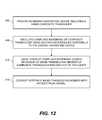
- FIG. 12is a block diagram describing an example embodiment of a method of harvesting energy using a MEMS composite transducer.
- Embodiments of the present inventioninclude a variety of types of MEMS transducers including a MEMS transducing member and a compliant membrane positioned in contact with the MEMS transducing member, configured such that the MEMS composite transducer can be set into oscillation by excitations such as vibrations or pressure waves in gases, liquids, or solids, in order to convert such periodic excitation into electrical energy.
- the vibrationscan be transmitted to the MEMS composite transducer through, for example, direct or indirect mechanical contact with a vibrating body, or through sound wave propagation.
- MEMS componentsare specified to be between 1 micron and 100 microns in size. Although such dimensions characterize a number of embodiments, it is contemplated that some embodiments will include dimensions outside that range.
- FIG. 1Ashows a top view and FIG. 1B shows a cross-sectional view (along A-A′) of a first configuration of a MEMS composite transducer 100 , where the MEMS transducing member is a cantilevered beam 120 that is anchored at a first end 121 to a first surface 111 of a substrate 110 . Portions 113 of the substrate 110 define an outer boundary 114 of a cavity 115 .
- FIGS. 1Ashows a top view
- FIG. 1Bshows a cross-sectional view (along A-A′) of a first configuration of a MEMS composite transducer 100 , where the MEMS transducing member is a cantilevered beam 120 that is anchored at a first end 121 to a first surface 111 of a substrate 110 . Portions 113 of the substrate 110 define an outer boundary 114 of a cavity 115 .
- the cavity 115is substantially cylindrical and is a through hole that extends from a first surface 111 of substrate 110 (to which a portion of the MEMS transducing member is anchored) to a second surface 112 that is opposite first surface 111 .
- Other shapes of cavity 115are contemplated for other configurations (not shown) in which the cavity 115 does not extend all the way to the second surface 112 .
- Still other embodimentsare contemplated where the cavity shape is not cylindrical with circular symmetry.
- a portion of cantilevered beam 120extends over a portion of cavity 115 and terminates at second end 122 .
- the length L of the cantilevered beamextends from the anchored end 121 to the free end 122 .
- Cantilevered beam 120has a width w 1 at first end 121 and a width w 2 at second end 122 .
- w 1w 2
- MEMS transducers having an anchored beam cantilevering over a cavityare well known.
- a feature that distinguishes the MEMS composite transducer 100 from a conventional deviceis a compliant membrane 130 that is positioned in contact with the cantilevered beam 120 (one example, of a MEMS transducing member).
- Compliant membraneincludes a first portion 131 that covers the MEMS transducing member, a second portion 132 that is anchored to first surface 111 of substrate 110 , and a third portion 133 that overhangs cavity 115 while not contacting the MEMS transducing member.
- compliant membrane 130is removed such that it does not cover a portion of the MEMS transducing member near the first end 121 of cantilevered beam 120 , so that electrical contact can be made as is discussed in further detail below.
- second portion 132 of compliant membrane 130 that is anchored to substrate 110is anchored around the outer boundary 114 of cavity 115 . In other embodiments (not shown), it is contemplated that the second portion 132 would not extend entirely around outer boundary 114 .
- the portion (including end 122 ) of the cantilevered beam 120 that extends over at least a portion of cavity 115is free to move relative to cavity 115 .
- Such a bending motionis provided for example in an actuating mode by a MEMS transducing material (such as a piezoelectric material, or a shape memory alloy, or a thermal bimorph material) that expands or contracts relative to a reference material layer to which it is affixed when an electrical signal is applied, as is discussed in further detail below.
- a MEMS transducing materialsuch as a piezoelectric material, or a shape memory alloy, or a thermal bimorph material
- the MEMS transducertypically moves from being out of the cavity to into the cavity before it relaxes to its undeflected position.
- Some types of MEMS transducershave the capability of being driven both into and out of the cavity, and are also freely movable into and out of the cavity.
- compliant membrane 130Desirable properties of compliant membrane 130 are that it have a Young's modulus that is much less than the Young's modulus of typical MEMS transducing materials, that it have a relatively large elongation before breakage, and that it have excellent chemical resistance (for compatibility with MEMS manufacturing processes).
- Some polymers, including some epoxies,are well adapted to be used as a compliant membrane 130 . Examples include TMMR liquid resist or TMMF dry film, both being products of Tokyo Ohka Kogyo Co.
- the Young's modulus of cured TMMR or TMMFis about 2 GPa, as compared to approximately 70 GPa for a silicon oxide, around 100 GPa for a PZT piezoelectric, around 160 GPa for a platinum metal electrode, and around 300 GPa for silicon nitride.
- the Young's modulus of the typical MEMS transducing memberis at least a factor of 10 greater, and more typically more than a factor of 30 greater than that of the compliant membrane 130 .
- a benefit of a low Young's modulus of the compliant membraneis that this type of design allows for the compliant membrane to have negligible effect on the amount of deflection for the portion 131 of the compliant membrane that covers the MEMS transducing member, but is readily deflected in the portion 133 of compliant membrane 130 that is nearby the MEMS transducing member but not directly contacted by the MEMS transducing member.
- the elongation before breaking of cured TMMR or TMMFis around 5%, so that it is capable of large deflection without damage.
- the Young's modulus of the compliant membrane 130is much less than that of the typical MEMS transducing member, it has little effect on the resonant frequency of the MEMS composite transducer 100 if the MEMS transducing member (for example, cantilevered beam 120 ) and the compliant membrane 130 have comparable size. However, if the MEMS transducing member is significantly smaller than the compliant membrane 130 , the resonant frequency of the MEMS composite transducer can be significantly lowered.
- Providing a lower resonant frequency MEMS composite transduceris a feature that can be particularly beneficial in an energy harvesting device.
- piezoelectric energy harvesting devicesconvert mechanical strain into electric current or voltage. Typically such devices operate most efficiently when oscillating at mechanical resonance. However, many of the prevalent frequencies of motion in the environment tend to be in the low kilohertz range (including sound waves, other pressure waves and mechanical vibrations) down to 100 Hz and below (such as vibration from a motor powered at 60 Hz).
- a resonant frequency of 1 kHz or lower for a piezoelectric cantilevered beam thickness of about 1 microna beam length of around 750 microns or longer would be required. Not only is this undesirably large, a beam of this length and thickness can be somewhat fragile.
- example embodiments of MEMS composite transducers 100 suitable for use in an energy harvesting deviceare shown.
- the different embodiments within this familyhave different amounts of displacement or different resonant frequencies or different amounts of coupling between multiple cantilevered beams 120 extending over a portion of cavity 115 , and thereby are well suited to a variety of applications.
- FIG. 3shows a portion of an energy harvesting device 200 including a MEMS composite transducer 100 having four cantilevered beams 120 as the MEMS transducing members, each cantilevered beam 120 including a first end that is anchored to substrate 110 , and a second end 122 that is cantilevered over cavity 115 .
- a MEMS composite transducer 100having four cantilevered beams 120 as the MEMS transducing members, each cantilevered beam 120 including a first end that is anchored to substrate 110 , and a second end 122 that is cantilevered over cavity 115 .
- the length L of the cantilevered beams 120are less than 20% of the dimension D across cavity 115 .
- Dis the diameter of the cavity 115 .
- the widths w 1 (see FIG. IA) of the first ends 121 of the cantilevered beams 120are all substantially equal to each other, and the widths w 2 (see FIG. 1A ) of the second ends 122 of the cantilevered beams 120 are all substantially equal to each other.
- w 1w 2 in the example of FIG. 3 .
- Compliant membrane 130includes first portions 131 that cover the cantilevered beams 120 (as seen more clearly in the cross-sectional view through two cantilevered beams 120 in FIG. 4A ), a second portion 132 that is anchored to substrate 110 , and a third portion 133 that overhangs cavity 115 while not contacting the cantilevered beams 120 . Portions 134 of the compliant membrane are removed provide access to electrical contacts to the cantilevered beams 120 .
- FIG. 4Ashows a cross-sectional view through two of the cantilevered beams 120 and compliant membrane 130 of FIG. 3 in an undeflected state.
- FIG. 4Bshows a similar cross-sectional view, but where the compliant membrane 130 has been deflected (for example, set into oscillation by an external excitation).
- the deflected compliant membrane 130being in contact with the cantilevered beams 120 , causes the cantilevered beams 120 also to deflect upward.
- the cantilevered beams 120are caused to deflect downward. Even a low frequency oscillation can cause a short MEMS transducing member having a high resonant frequency to deflect because of the coupling of motion from the compliant membrane 130 of the MEMS composite transducer 100 . Without compliant membrane 130 coupling the oscillation to the cantilevered beams 120 , cantilevered beams 120 are not deflected appreciably by the low frequency external excitation.
- the alternating upward and downward deflection of compliant membrane 130results in alternating compression and tension within the cantilevered beams 120 , thereby generating an AC voltage.
- the AC output of an energy harvesting device 200is typically connected to a rectifier 210 to provide a DC voltage.
- the output of rectifier 210is optionally smoothed by a filter 220 , and is connected to an energy storage device 230 , such as a capacitor or a battery.
- a regulator(not shown) can be provided between the filter 220 and the energy storage device 230 .
- any or all of filter 220 , energy storage device 230 and electrical device 250can also be integrated onto the same substrate 110 , or they can be packaged as a hybrid circuit, or they can be connected with wires.
- energy harvesting device 200rectifier 210 , filter 220 , energy storage device 230 and electrical device 250 together in a single microelectronic package, so that no wiring harness is required for electrical connection.
- Energy harvesting device 200 , rectifier 210 , optional filter 220 (and optional regulator) and energy storage device 230are together considered to be part of an energy harvesting apparatus.
- Electrical device 250is shown connected to energy storage device 230 by a dashed line, because it is using energy, not harvesting energy, so it is not part of the energy harvesting apparatus, even though in some embodiments it can be integrated together within the same substrate.
- FIG. 5shows an embodiment of an energy harvesting device 200 similar to FIG. 3 in which there are two groups of cantilevered beams 120 and 125 , with the elements of the two groups being alternatingly arranged.
- the lengths L and L′ of the cantilevered beams 120 and 125 respectivelyare less than 20% of the dimension D across cavity 115 .
- Dis the diameter of the cavity 115 .
- the lengths L and L′are different from each other, the first widths w 1 and w 1 ′ are different from each other, and the second widths w 2 and w 2 ′ are different from each other for the cantilevered beams 120 and 125 .
- Such an embodimentcan be beneficial if the groups of both geometries of cantilevered beams 120 and 125 are used to convert a motion of compliant membrane 130 to an electrical signal, and it is desired to pick up different amounts of deflection or at different frequencies. While the embodiment of FIG. 5 includes eight cantilevered beams 120 and 125 , other embodiments (not shown) can include many more cantilevered beams.
- the cantilevered beams 120are disposed width substantially radial symmetry around a circular cavity 115 . This can be a preferred type of configuration in many embodiments, but other embodiments are contemplated having nonradial symmetry or noncircular cavities.
- MEMS composite transducer 100 for an energy harvesting deviceinclude an attached mass 118 , as shown in FIGS. 6A and 6B , in order to further lower the resonant frequency.
- the mass 118can be attached to the portion 133 of the compliant membrane 130 that overhangs cavity 115 but does not contact the MEMS transducing member, for example.
- mass 118extends below portion 133 of compliant membrane 130 , so that it is located within the cavity 115 .
- mass 118can be affixed to the opposite side of the compliant membrane 130 , as shown in FIG.
- FIG. 6Ashows a cross-sectional view with compliant membrane 130 deflected upward along axis 117 of cavity 115 , while FIG.
- FIG. 7Bshows a similar cross-sectional view with compliant membrane 130 deflected downward along axis 117 into cavity 115 , such that mass 118 extends within recess 185 of mounting member 180 .
- the attached mass 118can be formed by patterning an additional layer over the compliant membrane 130 . In other embodiments there can be an attached mass 118 on both sides of the compliant membrane.
- mass 118is disposed at or near the center of compliant membrane 118 . Further, in some embodiments, mass 118 is disposed symmetrically about a center of compliant membrane 130 . In such cases, the mass 118 can also be disposed at the center of compliant membrane 130 , but in other embodiments the mass 118 is not disposed at the center of the compliant membrane. Different distributions of mass 118 attached to compliant membrane 130 can facilitate excitation of different vibrational modes having different resonant frequency.
- the MEMS transducing mechanismsinclude a deflection out of the plane of the undeflected MEMS composite transducer, for example, a bending motion.
- a bending motionit is advantageous in some embodiments to include in the MEMS transducing member a piezoelectric MEMS transducing material 160 in contact with a reference material 162 , as shown for the cantilevered beam 120 in FIG. 8 .
- the MEMS transducing material 160is shown on top of reference material 162 , but alternatively the reference material 162 can be on top of the MEMS transducing material 160 .
- Reference material 162can include one or more insulator layers such as silicon oxide or silicon nitride, as well as one or more conductor layers to serve as electrodes. It is preferable to design the relative thicknesses t 1 and t 2 of the piezoelectric MEMS transducing material 160 and the reference material 162 such that the neutral axis (on either side of which stress and strain change sign) is not within the MEMS transducing material 160 . In other words, it is desired for efficiency of conversion from strain to voltage in the piezoelectric material that when the cantilevered beam 120 is deflected upward, the piezoelectric MEMS transducing material either be completely in compression or completely in tension throughout the cantilevered beam 120 . Similarly, when the cantilevered beam 120 is deflected downward, it is desired that the piezoelectric MEMS transducing material either be completely in tension or completely in compression throughout the cantilevered beam 120 .
- Piezoelectric materialsare particularly advantageous for use in MEMS composite transducer for an energy harvesting device, because of their ability to convert a strain into an electrical signal.
- piezoelectric materialsThere are a variety of types of piezoelectric materials.
- a family of interestincludes piezoelectric ceramics, such as lead zirconate titanate or PZT.
- an energy harvesting device 200that is effective in converting a wide range of frequencies of mechanical or pressure wave excitation into electrical energy.
- One way to broaden the frequency responseis to add damping into oscillating MEMS composite transducers. However, that often reduces the amplitude of oscillation near resonance.
- a preferred approachis to provide an array of MEMS composite transducers having different resonant frequencies, but a relatively low amount of damping. It is preferable for the damping of oscillation of the MEMS composite transducer of the energy harvesting device to be due primarily to conversion of mechanical energy into electrical energy, rather than to include additional sources of mechanical damping.
- the damping of oscillations of the MEMS composite transducer in an energy harvesting deviceis reduced by enclosing the device in a hermetically sealed housing 205 (shown in FIG. 11A ) from which air has been removed.
- FIG. 9shows a portion of an energy harvesting device 200 including a lower frequency MEMS composite transducer 101 , a middle frequency MEMS composite transducer 102 and a higher frequency MEMS composite transducer 103 that are all formed together on a single substrate 110 .
- Each of the MEMS composite transducersis similar in that they include a cavity 115 , at least one cantilevered beam 120 , a compliant membrane 130 , and optionally a mass 118 attached to the compliant membrane 130 .
- Cavities 115 for MEMS composite transducers 101 , 102 and 103have diameters D 1 , D 2 and D 3 respectively, where D 1 >D 2 >D 3 .
- lower frequency MEMS composite transducerstend to have a larger diameter of cavity 115 .
- Lower frequency MEMS composite transducersalso tend to have a larger mass 118 affixed to compliant membrane 130 .
- the length L of cantilevered beam 120 from its anchored first end to its free second endis longer for MEMS composite transducer 101 than it is for MEMS composite transducers 102 or 103 .
- the rectifier 210 , filter 220 , and energy storage device 230that are part of the corresponding energy harvesting apparatus, as well as the electrical energy device 250 that is powered thereby.
- Energy harvesting devices 200are not limited to arrays of MEMS composite transducers having three different resonant frequencies. Depending upon the range of frequencies that are desired to convert to electrical energy in a particular application, an energy harvesting device 200 can include a plurality of MEMS composite transducers having different resonant frequencies, thereby providing a wider range of vibration frequency sensitivity than would an energy harvesting device not including a plurality of MEMS composite transducers having different resonant frequencies.
- FIG. 10schematically shows three intensity curves as a function of driving frequency (where intensity is the square of the amplitude of oscillation) for three different lightly damped MEMS composite transducers, having different resonant frequencies.
- curve 301corresponding to MEMS composite oscillator 101
- curve 302corresponding to MEMS composite oscillator 102
- curve 303corresponding to MEMS composite oscillator 103
- f 2the driving frequency
- the intensity curves 301 , 302 and 303overlap somewhat, so even for excitations that are not at one of the resonant frequencies, a reasonable amount of electrical signal can be generated in the energy harvesting device 200 and used to charge energy storage device 230 or power electrical device 250 (see, for example, FIG. 9 ).
- At least one MEMS composite transducer 100is provided, step 400 , including a substrate 110 having a cavity 115 with at least one cantilevered beam 120 and a compliant membrane 130 in contact with the cantilevered beam 120 and anchored to the substrate.
- the energy harvesting deviceis configured so that the compliant membrane 130 is set into oscillation by excitations produced external to the energy harvesting device, step 405 .
- excitationscould include mechanical vibrations of an object, or pressure waves (including sound waves, or other types of pressure pulses in fluids).
- the oscillating compliant membrane 130moves the cantilevered beam 120 into and out of cavity 115 , step 410 .
- cantilevered beam 120includes a piezoelectric material
- the motion of cantilevered beamis converted into an electrical signal, step 415 .
- an AC electrical signalis provided as the cantilevered beam 120 is deflected into and out of cavity 115 , thereby alternatingly being put into tension and compression.
- the AC electrical signalis rectified by rectifier 210 , and optionally filtered by filter 220 .
- the rectified signalis typically used to provide a trickle charge to an energy storage device 230 , which can be a capacitor or a battery, for example.
- an energy harvesting deviceis particularly well-suited for providing power to electrical devices that require low amounts of energy, or that are intermittently operated.
- Smoke detectors and camera flashesare examples of devices that are intermittently operated.
- An energy harvesting devicecan be used to charge an energy storage device for such an intermittently operated device. Although a relatively high amount of energy is required when the device is operated, use can be infrequent enough so that energy harvesting device can sufficiently charge the energy storage device between operations.
- FIG. 11Ashows an energy harvesting device 200 including a plurality of MEMS composite transducers 100 of the types described earlier relative to FIGS. 3-9 .
- Axis 117 of cavities 115is indicated.
- Mounting member 180(see FIGS. 7A and 7B ) is not shown but can be affixed to housing 205 .
- housing 205can be hermetically sealed and a partial vacuum provided within housing 205 for reduction of damping of oscillations of the MEMS composite transducers.
- Energy harvesting device 200is in mechanical contact with an object 260 that tends to vibrate. Mechanical contact can be provided by affixing the energy harvesting device 200 to object 260 using adhesives, screws, clamps, or the like.
- the energy harvesting device 200is affixed to the object 260 in a predetermined relative orientation.
- the predetermined relative orientationcan be selected according to a known vibration mode of the object 200 having an axis 265 of vibration that is substantially perpendicular to a plane in which MEMS composite transducer 100 is disposed. Equivalently, it can be said that the predetermined relative orientation can be selected according to a known vibration mode of the object 200 having an axis 265 of vibration that is substantially parallel to axis 117 of cavity 115 .
- FIG. 11Bshows an energy harvesting device 200 including a plurality of MEMS composite transducers 100 of the types described earlier relative to FIGS. 3-9 .
- Axis 117 of cavities 115is indicated.
- Pressure waves 270are shown traveling along propagation direction 275 toward energy harvesting device 200 .
- Pressure waves 270can include sound waves or other sorts of longitudinal waves (also called compression waves) that can be propagated through a gas (such as air) or a liquid (such as water or blood). It is desirable to configure energy harvesting device 200 so that compliant membrane 130 of MEMS composite transducer 100 is set into oscillation by the pressure waves.
- the energy harvesting device 200it is preferable to orient the energy harvesting device 200 in a predetermined orientation, such that axis 117 of the cavity 115 is oriented along a direction that is substantially parallel to a propagation direction 275 of the pressure waves 270 .
- Other components of the energy harvesting apparatusrectifier, filter, regulator and energy storage device are not shown in FIGS. 11A and 11B .
Landscapes
- Physics & Mathematics (AREA)
- Engineering & Computer Science (AREA)
- Acoustics & Sound (AREA)
- Signal Processing (AREA)
- Health & Medical Sciences (AREA)
- Otolaryngology (AREA)
- Micromachines (AREA)
Abstract
Description
δ=3σ(1−ν(L2/Et2 (1),
where ν is Poisson's ratio, E is Young's modulus, L is the beam length, and t is the thickness of the cantilevered beam. In order to increase the amount of deflection for a cantilevered beam, one can use a longer beam length, a smaller thickness, a higher stress, a lower Poisson's ratio, or a lower Young's modulus. The resonant frequency of vibration of an undamped cantilevered beam is given by
f=ω0/2π=(k/m)1/2/2π, (2),
where k is the spring constant and m is the mass. For a cantilevered beam of constant width w, the spring constant k is given by
k=Ewt3/4L3 (3).
It can be shown that the dynamic mass m of an oscillating cantilevered beam is approximately one quarter of the actual mass of ρwtL (ρ being the density of the beam material), so that within a few percent, the resonant frequency of vibration of an undamped cantilevered beam is approximately
f˜(t/2πL2) (E/ρ)1/2 (4).
For a lower resonant frequency one can use a smaller Young's modulus, a smaller thickness, a longer length, or a larger density. A doubly anchored beam typically has a lower amount of deflection and a higher resonant frequency than a cantilevered beam having comparable geometry and materials. A clamped sheet typically has an even lower amount of deflection and an even higher resonant frequency.
- 100 MEMS composite transducer
- 101 Lower frequency MEMS composite transducer
- 102 Middle frequency MEMS composite transducer
- 103 Higher frequency MEMS composite transducer
- 110 Substrate
- 111 First surface of substrate
- 112 Second surface of substrate
- 113 Portions of substrate (defining outer boundary of cavity)
- 114 Outer boundary
- 115 Cavity
- 117 Axis of cavity
- 116 Through hole (fluid inlet)
- 118 Mass
- 120 Cantilevered beam
- 121 Anchored end (of cantilevered beam)
- 122 Cantilevered end (of cantilevered beam)
- 125 Cantilevered beam
- 130 Compliant membrane
- 131 Covering portion of compliant membrane
- 132 Anchoring portion of compliant membrane
- 133 Portion of compliant membrane overhanging cavity
- 134 Portion where compliant membrane is removed
- 160 MEMS transducing material
- 162 Reference material
- 180 Mounting member
- 185 Recess
- 200 Energy harvesting device
- 205 Housing
- 210 Rectifier
- 220 Filter
- 230 Energy storage device
- 250 Electrical device
- 260 Vibrating object
- 265 Axis of vibration (of vibrating object)
- 270 Pressure waves
- 275 Propagation direction
- 301 Intensity curve for lower resonant frequency
- 302 Intensity curve for middle resonant frequency
- 303 Intensity curve for higher resonant frequency
- 400 Provide an energy harvesting device including a MEMS composite transducer
- 405 Oscillate compliant membrane of composite transducer using excitations produced externally to the energy harvesting device
- 410 Oscillation of compliant membrane causes movement of MEMS transducing member of composite transducer into and out of the cavity
- 415 Convert motion of MEMS transducing member into an electrical signal.
Claims (28)
Priority Applications (2)
| Application Number | Priority Date | Filing Date | Title |
|---|---|---|---|
| US13/089,507US8759990B2 (en) | 2011-04-19 | 2011-04-19 | Energy harvesting device including MEMS composite transducer |
| PCT/US2012/033866WO2012145279A2 (en) | 2011-04-19 | 2012-04-17 | Energy harvesting device including mems composite transducer |
Applications Claiming Priority (1)
| Application Number | Priority Date | Filing Date | Title |
|---|---|---|---|
| US13/089,507US8759990B2 (en) | 2011-04-19 | 2011-04-19 | Energy harvesting device including MEMS composite transducer |
Publications (2)
| Publication Number | Publication Date |
|---|---|
| US20120267900A1 US20120267900A1 (en) | 2012-10-25 |
| US8759990B2true US8759990B2 (en) | 2014-06-24 |
Family
ID=47020703
Family Applications (1)
| Application Number | Title | Priority Date | Filing Date |
|---|---|---|---|
| US13/089,507Expired - Fee RelatedUS8759990B2 (en) | 2011-04-19 | 2011-04-19 | Energy harvesting device including MEMS composite transducer |
Country Status (1)
| Country | Link |
|---|---|
| US (1) | US8759990B2 (en) |
Cited By (1)
| Publication number | Priority date | Publication date | Assignee | Title |
|---|---|---|---|---|
| US20150260518A1 (en)* | 2012-09-04 | 2015-09-17 | Julius Georgiou | Hybrid mems microfluidic gyroscope |
Families Citing this family (201)
| Publication number | Priority date | Publication date | Assignee | Title |
|---|---|---|---|---|
| US8680752B2 (en)* | 2011-02-11 | 2014-03-25 | Georgia Tech Research Corporation | Piezoelectric micromechanical energy harvesters |
| US8680695B2 (en)* | 2011-04-19 | 2014-03-25 | Eastman Kodak Company | Energy harvesting using MEMS composite transducer |
| US20130088020A1 (en)* | 2011-10-11 | 2013-04-11 | Lalitha Vellore Sripathi Rao | Method, System, Apparatus to generate electricity from objects under motion |
| US9948135B2 (en) | 2015-09-22 | 2018-04-17 | Energous Corporation | Systems and methods for identifying sensitive objects in a wireless charging transmission field |
| US9973021B2 (en) | 2012-07-06 | 2018-05-15 | Energous Corporation | Receivers for wireless power transmission |
| US10218227B2 (en) | 2014-05-07 | 2019-02-26 | Energous Corporation | Compact PIFA antenna |
| US10224982B1 (en) | 2013-07-11 | 2019-03-05 | Energous Corporation | Wireless power transmitters for transmitting wireless power and tracking whether wireless power receivers are within authorized locations |
| US9871398B1 (en) | 2013-07-01 | 2018-01-16 | Energous Corporation | Hybrid charging method for wireless power transmission based on pocket-forming |
| US9867062B1 (en) | 2014-07-21 | 2018-01-09 | Energous Corporation | System and methods for using a remote server to authorize a receiving device that has requested wireless power and to determine whether another receiving device should request wireless power in a wireless power transmission system |
| US10063105B2 (en) | 2013-07-11 | 2018-08-28 | Energous Corporation | Proximity transmitters for wireless power charging systems |
| US9853692B1 (en) | 2014-05-23 | 2017-12-26 | Energous Corporation | Systems and methods for wireless power transmission |
| US10050462B1 (en) | 2013-08-06 | 2018-08-14 | Energous Corporation | Social power sharing for mobile devices based on pocket-forming |
| US9787103B1 (en) | 2013-08-06 | 2017-10-10 | Energous Corporation | Systems and methods for wirelessly delivering power to electronic devices that are unable to communicate with a transmitter |
| US10090886B1 (en) | 2014-07-14 | 2018-10-02 | Energous Corporation | System and method for enabling automatic charging schedules in a wireless power network to one or more devices |
| US11502551B2 (en) | 2012-07-06 | 2022-11-15 | Energous Corporation | Wirelessly charging multiple wireless-power receivers using different subsets of an antenna array to focus energy at different locations |
| US10199835B2 (en) | 2015-12-29 | 2019-02-05 | Energous Corporation | Radar motion detection using stepped frequency in wireless power transmission system |
| US9893768B2 (en) | 2012-07-06 | 2018-02-13 | Energous Corporation | Methodology for multiple pocket-forming |
| US9887584B1 (en) | 2014-08-21 | 2018-02-06 | Energous Corporation | Systems and methods for a configuration web service to provide configuration of a wireless power transmitter within a wireless power transmission system |
| US10193396B1 (en) | 2014-05-07 | 2019-01-29 | Energous Corporation | Cluster management of transmitters in a wireless power transmission system |
| US10211674B1 (en) | 2013-06-12 | 2019-02-19 | Energous Corporation | Wireless charging using selected reflectors |
| US10008889B2 (en) | 2014-08-21 | 2018-06-26 | Energous Corporation | Method for automatically testing the operational status of a wireless power receiver in a wireless power transmission system |
| US9900057B2 (en) | 2012-07-06 | 2018-02-20 | Energous Corporation | Systems and methods for assigning groups of antenas of a wireless power transmitter to different wireless power receivers, and determining effective phases to use for wirelessly transmitting power using the assigned groups of antennas |
| US9954374B1 (en) | 2014-05-23 | 2018-04-24 | Energous Corporation | System and method for self-system analysis for detecting a fault in a wireless power transmission Network |
| US9838083B2 (en) | 2014-07-21 | 2017-12-05 | Energous Corporation | Systems and methods for communication with remote management systems |
| US9793758B2 (en) | 2014-05-23 | 2017-10-17 | Energous Corporation | Enhanced transmitter using frequency control for wireless power transmission |
| US9887739B2 (en) | 2012-07-06 | 2018-02-06 | Energous Corporation | Systems and methods for wireless power transmission by comparing voltage levels associated with power waves transmitted by antennas of a plurality of antennas of a transmitter to determine appropriate phase adjustments for the power waves |
| US10063064B1 (en) | 2014-05-23 | 2018-08-28 | Energous Corporation | System and method for generating a power receiver identifier in a wireless power network |
| US10291055B1 (en) | 2014-12-29 | 2019-05-14 | Energous Corporation | Systems and methods for controlling far-field wireless power transmission based on battery power levels of a receiving device |
| US9843213B2 (en) | 2013-08-06 | 2017-12-12 | Energous Corporation | Social power sharing for mobile devices based on pocket-forming |
| US9859797B1 (en) | 2014-05-07 | 2018-01-02 | Energous Corporation | Synchronous rectifier design for wireless power receiver |
| US10256657B2 (en) | 2015-12-24 | 2019-04-09 | Energous Corporation | Antenna having coaxial structure for near field wireless power charging |
| US9991741B1 (en) | 2014-07-14 | 2018-06-05 | Energous Corporation | System for tracking and reporting status and usage information in a wireless power management system |
| US9143000B2 (en) | 2012-07-06 | 2015-09-22 | Energous Corporation | Portable wireless charging pad |
| US10263432B1 (en) | 2013-06-25 | 2019-04-16 | Energous Corporation | Multi-mode transmitter with an antenna array for delivering wireless power and providing Wi-Fi access |
| US10211680B2 (en) | 2013-07-19 | 2019-02-19 | Energous Corporation | Method for 3 dimensional pocket-forming |
| US20140008993A1 (en) | 2012-07-06 | 2014-01-09 | DvineWave Inc. | Methodology for pocket-forming |
| US9876379B1 (en) | 2013-07-11 | 2018-01-23 | Energous Corporation | Wireless charging and powering of electronic devices in a vehicle |
| US10992187B2 (en) | 2012-07-06 | 2021-04-27 | Energous Corporation | System and methods of using electromagnetic waves to wirelessly deliver power to electronic devices |
| US10199849B1 (en) | 2014-08-21 | 2019-02-05 | Energous Corporation | Method for automatically testing the operational status of a wireless power receiver in a wireless power transmission system |
| US9912199B2 (en) | 2012-07-06 | 2018-03-06 | Energous Corporation | Receivers for wireless power transmission |
| US9876648B2 (en) | 2014-08-21 | 2018-01-23 | Energous Corporation | System and method to control a wireless power transmission system by configuration of wireless power transmission control parameters |
| US9843201B1 (en) | 2012-07-06 | 2017-12-12 | Energous Corporation | Wireless power transmitter that selects antenna sets for transmitting wireless power to a receiver based on location of the receiver, and methods of use thereof |
| US9923386B1 (en) | 2012-07-06 | 2018-03-20 | Energous Corporation | Systems and methods for wireless power transmission by modifying a number of antenna elements used to transmit power waves to a receiver |
| US9831718B2 (en) | 2013-07-25 | 2017-11-28 | Energous Corporation | TV with integrated wireless power transmitter |
| US9899873B2 (en) | 2014-05-23 | 2018-02-20 | Energous Corporation | System and method for generating a power receiver identifier in a wireless power network |
| US9824815B2 (en) | 2013-05-10 | 2017-11-21 | Energous Corporation | Wireless charging and powering of healthcare gadgets and sensors |
| US10312715B2 (en) | 2015-09-16 | 2019-06-04 | Energous Corporation | Systems and methods for wireless power charging |
| US10224758B2 (en) | 2013-05-10 | 2019-03-05 | Energous Corporation | Wireless powering of electronic devices with selective delivery range |
| US9438045B1 (en) | 2013-05-10 | 2016-09-06 | Energous Corporation | Methods and systems for maximum power point transfer in receivers |
| US9847679B2 (en) | 2014-05-07 | 2017-12-19 | Energous Corporation | System and method for controlling communication between wireless power transmitter managers |
| US9124125B2 (en) | 2013-05-10 | 2015-09-01 | Energous Corporation | Wireless power transmission with selective range |
| US10124754B1 (en) | 2013-07-19 | 2018-11-13 | Energous Corporation | Wireless charging and powering of electronic sensors in a vehicle |
| US9882430B1 (en) | 2014-05-07 | 2018-01-30 | Energous Corporation | Cluster management of transmitters in a wireless power transmission system |
| US10075008B1 (en) | 2014-07-14 | 2018-09-11 | Energous Corporation | Systems and methods for manually adjusting when receiving electronic devices are scheduled to receive wirelessly delivered power from a wireless power transmitter in a wireless power network |
| US10230266B1 (en) | 2014-02-06 | 2019-03-12 | Energous Corporation | Wireless power receivers that communicate status data indicating wireless power transmission effectiveness with a transmitter using a built-in communications component of a mobile device, and methods of use thereof |
| US10223717B1 (en) | 2014-05-23 | 2019-03-05 | Energous Corporation | Systems and methods for payment-based authorization of wireless power transmission service |
| US10128699B2 (en) | 2014-07-14 | 2018-11-13 | Energous Corporation | Systems and methods of providing wireless power using receiver device sensor inputs |
| US10141791B2 (en) | 2014-05-07 | 2018-11-27 | Energous Corporation | Systems and methods for controlling communications during wireless transmission of power using application programming interfaces |
| US9941747B2 (en) | 2014-07-14 | 2018-04-10 | Energous Corporation | System and method for manually selecting and deselecting devices to charge in a wireless power network |
| US9876394B1 (en) | 2014-05-07 | 2018-01-23 | Energous Corporation | Boost-charger-boost system for enhanced power delivery |
| US9893555B1 (en) | 2013-10-10 | 2018-02-13 | Energous Corporation | Wireless charging of tools using a toolbox transmitter |
| US9939864B1 (en) | 2014-08-21 | 2018-04-10 | Energous Corporation | System and method to control a wireless power transmission system by configuration of wireless power transmission control parameters |
| US10186913B2 (en) | 2012-07-06 | 2019-01-22 | Energous Corporation | System and methods for pocket-forming based on constructive and destructive interferences to power one or more wireless power receivers using a wireless power transmitter including a plurality of antennas |
| US9899861B1 (en) | 2013-10-10 | 2018-02-20 | Energous Corporation | Wireless charging methods and systems for game controllers, based on pocket-forming |
| US10270261B2 (en) | 2015-09-16 | 2019-04-23 | Energous Corporation | Systems and methods of object detection in wireless power charging systems |
| US10063106B2 (en) | 2014-05-23 | 2018-08-28 | Energous Corporation | System and method for a self-system analysis in a wireless power transmission network |
| US10206185B2 (en) | 2013-05-10 | 2019-02-12 | Energous Corporation | System and methods for wireless power transmission to an electronic device in accordance with user-defined restrictions |
| US9893554B2 (en) | 2014-07-14 | 2018-02-13 | Energous Corporation | System and method for providing health safety in a wireless power transmission system |
| US10211682B2 (en) | 2014-05-07 | 2019-02-19 | Energous Corporation | Systems and methods for controlling operation of a transmitter of a wireless power network based on user instructions received from an authenticated computing device powered or charged by a receiver of the wireless power network |
| US9941707B1 (en) | 2013-07-19 | 2018-04-10 | Energous Corporation | Home base station for multiple room coverage with multiple transmitters |
| US10141768B2 (en) | 2013-06-03 | 2018-11-27 | Energous Corporation | Systems and methods for maximizing wireless power transfer efficiency by instructing a user to change a receiver device's position |
| US9966765B1 (en) | 2013-06-25 | 2018-05-08 | Energous Corporation | Multi-mode transmitter |
| US9906065B2 (en) | 2012-07-06 | 2018-02-27 | Energous Corporation | Systems and methods of transmitting power transmission waves based on signals received at first and second subsets of a transmitter's antenna array |
| US10965164B2 (en) | 2012-07-06 | 2021-03-30 | Energous Corporation | Systems and methods of wirelessly delivering power to a receiver device |
| US10103582B2 (en) | 2012-07-06 | 2018-10-16 | Energous Corporation | Transmitters for wireless power transmission |
| US9891669B2 (en) | 2014-08-21 | 2018-02-13 | Energous Corporation | Systems and methods for a configuration web service to provide configuration of a wireless power transmitter within a wireless power transmission system |
| US10291066B1 (en) | 2014-05-07 | 2019-05-14 | Energous Corporation | Power transmission control systems and methods |
| US9252628B2 (en) | 2013-05-10 | 2016-02-02 | Energous Corporation | Laptop computer as a transmitter for wireless charging |
| US9882427B2 (en) | 2013-05-10 | 2018-01-30 | Energous Corporation | Wireless power delivery using a base station to control operations of a plurality of wireless power transmitters |
| US9859756B2 (en) | 2012-07-06 | 2018-01-02 | Energous Corporation | Transmittersand methods for adjusting wireless power transmission based on information from receivers |
| US9847677B1 (en) | 2013-10-10 | 2017-12-19 | Energous Corporation | Wireless charging and powering of healthcare gadgets and sensors |
| US10148097B1 (en) | 2013-11-08 | 2018-12-04 | Energous Corporation | Systems and methods for using a predetermined number of communication channels of a wireless power transmitter to communicate with different wireless power receivers |
| US10128693B2 (en) | 2014-07-14 | 2018-11-13 | Energous Corporation | System and method for providing health safety in a wireless power transmission system |
| US10038337B1 (en) | 2013-09-16 | 2018-07-31 | Energous Corporation | Wireless power supply for rescue devices |
| US9853458B1 (en) | 2014-05-07 | 2017-12-26 | Energous Corporation | Systems and methods for device and power receiver pairing |
| US10992185B2 (en) | 2012-07-06 | 2021-04-27 | Energous Corporation | Systems and methods of using electromagnetic waves to wirelessly deliver power to game controllers |
| US9812890B1 (en) | 2013-07-11 | 2017-11-07 | Energous Corporation | Portable wireless charging pad |
| US12057715B2 (en) | 2012-07-06 | 2024-08-06 | Energous Corporation | Systems and methods of wirelessly delivering power to a wireless-power receiver device in response to a change of orientation of the wireless-power receiver device |
| US10205239B1 (en) | 2014-05-07 | 2019-02-12 | Energous Corporation | Compact PIFA antenna |
| US10439448B2 (en) | 2014-08-21 | 2019-10-08 | Energous Corporation | Systems and methods for automatically testing the communication between wireless power transmitter and wireless power receiver |
| US9941754B2 (en) | 2012-07-06 | 2018-04-10 | Energous Corporation | Wireless power transmission with selective range |
| US10381880B2 (en) | 2014-07-21 | 2019-08-13 | Energous Corporation | Integrated antenna structure arrays for wireless power transmission |
| US9806564B2 (en) | 2014-05-07 | 2017-10-31 | Energous Corporation | Integrated rectifier and boost converter for wireless power transmission |
| US9368020B1 (en) | 2013-05-10 | 2016-06-14 | Energous Corporation | Off-premises alert system and method for wireless power receivers in a wireless power network |
| US10243414B1 (en) | 2014-05-07 | 2019-03-26 | Energous Corporation | Wearable device with wireless power and payload receiver |
| US9859757B1 (en) | 2013-07-25 | 2018-01-02 | Energous Corporation | Antenna tile arrangements in electronic device enclosures |
| US10090699B1 (en) | 2013-11-01 | 2018-10-02 | Energous Corporation | Wireless powered house |
| US9825674B1 (en) | 2014-05-23 | 2017-11-21 | Energous Corporation | Enhanced transmitter that selects configurations of antenna elements for performing wireless power transmission and receiving functions |
| US20150326070A1 (en) | 2014-05-07 | 2015-11-12 | Energous Corporation | Methods and Systems for Maximum Power Point Transfer in Receivers |
| US9913321B2 (en)* | 2013-01-25 | 2018-03-06 | Energyield, Llc | Energy harvesting container |
| US9866279B2 (en) | 2013-05-10 | 2018-01-09 | Energous Corporation | Systems and methods for selecting which power transmitter should deliver wireless power to a receiving device in a wireless power delivery network |
| US9537357B2 (en) | 2013-05-10 | 2017-01-03 | Energous Corporation | Wireless sound charging methods and systems for game controllers, based on pocket-forming |
| US9419443B2 (en) | 2013-05-10 | 2016-08-16 | Energous Corporation | Transducer sound arrangement for pocket-forming |
| US9538382B2 (en) | 2013-05-10 | 2017-01-03 | Energous Corporation | System and method for smart registration of wireless power receivers in a wireless power network |
| US9819230B2 (en) | 2014-05-07 | 2017-11-14 | Energous Corporation | Enhanced receiver for wireless power transmission |
| US10103552B1 (en) | 2013-06-03 | 2018-10-16 | Energous Corporation | Protocols for authenticated wireless power transmission |
| US10003211B1 (en) | 2013-06-17 | 2018-06-19 | Energous Corporation | Battery life of portable electronic devices |
| US10021523B2 (en) | 2013-07-11 | 2018-07-10 | Energous Corporation | Proximity transmitters for wireless power charging systems |
| US9979440B1 (en) | 2013-07-25 | 2018-05-22 | Energous Corporation | Antenna tile arrangements configured to operate as one functional unit |
| US10075017B2 (en) | 2014-02-06 | 2018-09-11 | Energous Corporation | External or internal wireless power receiver with spaced-apart antenna elements for charging or powering mobile devices using wirelessly delivered power |
| US9935482B1 (en) | 2014-02-06 | 2018-04-03 | Energous Corporation | Wireless power transmitters that transmit at determined times based on power availability and consumption at a receiving mobile device |
| US10158257B2 (en) | 2014-05-01 | 2018-12-18 | Energous Corporation | System and methods for using sound waves to wirelessly deliver power to electronic devices |
| US9966784B2 (en)* | 2014-06-03 | 2018-05-08 | Energous Corporation | Systems and methods for extending battery life of portable electronic devices charged by sound |
| US10153653B1 (en) | 2014-05-07 | 2018-12-11 | Energous Corporation | Systems and methods for using application programming interfaces to control communications between a transmitter and a receiver |
| US9800172B1 (en) | 2014-05-07 | 2017-10-24 | Energous Corporation | Integrated rectifier and boost converter for boosting voltage received from wireless power transmission waves |
| US10170917B1 (en) | 2014-05-07 | 2019-01-01 | Energous Corporation | Systems and methods for managing and controlling a wireless power network by establishing time intervals during which receivers communicate with a transmitter |
| US9973008B1 (en) | 2014-05-07 | 2018-05-15 | Energous Corporation | Wireless power receiver with boost converters directly coupled to a storage element |
| US10153645B1 (en) | 2014-05-07 | 2018-12-11 | Energous Corporation | Systems and methods for designating a master power transmitter in a cluster of wireless power transmitters |
| US9876536B1 (en) | 2014-05-23 | 2018-01-23 | Energous Corporation | Systems and methods for assigning groups of antennas to transmit wireless power to different wireless power receivers |
| US10797617B2 (en)* | 2014-07-07 | 2020-10-06 | Commonwealth Scientific And Industrial Research Organisation | Electromechanical transducer |
| US10068703B1 (en) | 2014-07-21 | 2018-09-04 | Energous Corporation | Integrated miniature PIFA with artificial magnetic conductor metamaterials |
| US10116143B1 (en) | 2014-07-21 | 2018-10-30 | Energous Corporation | Integrated antenna arrays for wireless power transmission |
| US9871301B2 (en) | 2014-07-21 | 2018-01-16 | Energous Corporation | Integrated miniature PIFA with artificial magnetic conductor metamaterials |
| US9917477B1 (en) | 2014-08-21 | 2018-03-13 | Energous Corporation | Systems and methods for automatically testing the communication between power transmitter and wireless receiver |
| US9965009B1 (en) | 2014-08-21 | 2018-05-08 | Energous Corporation | Systems and methods for assigning a power receiver to individual power transmitters based on location of the power receiver |
| US10122415B2 (en) | 2014-12-27 | 2018-11-06 | Energous Corporation | Systems and methods for assigning a set of antennas of a wireless power transmitter to a wireless power receiver based on a location of the wireless power receiver |
| US9893535B2 (en) | 2015-02-13 | 2018-02-13 | Energous Corporation | Systems and methods for determining optimal charging positions to maximize efficiency of power received from wirelessly delivered sound wave energy |
| US10523033B2 (en) | 2015-09-15 | 2019-12-31 | Energous Corporation | Receiver devices configured to determine location within a transmission field |
| US12283828B2 (en) | 2015-09-15 | 2025-04-22 | Energous Corporation | Receiver devices configured to determine location within a transmission field |
| US9906275B2 (en) | 2015-09-15 | 2018-02-27 | Energous Corporation | Identifying receivers in a wireless charging transmission field |
| US10778041B2 (en) | 2015-09-16 | 2020-09-15 | Energous Corporation | Systems and methods for generating power waves in a wireless power transmission system |
| US9941752B2 (en) | 2015-09-16 | 2018-04-10 | Energous Corporation | Systems and methods of object detection in wireless power charging systems |
| US9893538B1 (en) | 2015-09-16 | 2018-02-13 | Energous Corporation | Systems and methods of object detection in wireless power charging systems |
| US11710321B2 (en) | 2015-09-16 | 2023-07-25 | Energous Corporation | Systems and methods of object detection in wireless power charging systems |
| US10158259B1 (en) | 2015-09-16 | 2018-12-18 | Energous Corporation | Systems and methods for identifying receivers in a transmission field by transmitting exploratory power waves towards different segments of a transmission field |
| US10199850B2 (en) | 2015-09-16 | 2019-02-05 | Energous Corporation | Systems and methods for wirelessly transmitting power from a transmitter to a receiver by determining refined locations of the receiver in a segmented transmission field associated with the transmitter |
| US9871387B1 (en) | 2015-09-16 | 2018-01-16 | Energous Corporation | Systems and methods of object detection using one or more video cameras in wireless power charging systems |
| US10008875B1 (en) | 2015-09-16 | 2018-06-26 | Energous Corporation | Wireless power transmitter configured to transmit power waves to a predicted location of a moving wireless power receiver |
| US10211685B2 (en) | 2015-09-16 | 2019-02-19 | Energous Corporation | Systems and methods for real or near real time wireless communications between a wireless power transmitter and a wireless power receiver |
| US10186893B2 (en) | 2015-09-16 | 2019-01-22 | Energous Corporation | Systems and methods for real time or near real time wireless communications between a wireless power transmitter and a wireless power receiver |
| US10050470B1 (en) | 2015-09-22 | 2018-08-14 | Energous Corporation | Wireless power transmission device having antennas oriented in three dimensions |
| US10135294B1 (en) | 2015-09-22 | 2018-11-20 | Energous Corporation | Systems and methods for preconfiguring transmission devices for power wave transmissions based on location data of one or more receivers |
| US10135295B2 (en) | 2015-09-22 | 2018-11-20 | Energous Corporation | Systems and methods for nullifying energy levels for wireless power transmission waves |
| US10033222B1 (en) | 2015-09-22 | 2018-07-24 | Energous Corporation | Systems and methods for determining and generating a waveform for wireless power transmission waves |
| US10020678B1 (en) | 2015-09-22 | 2018-07-10 | Energous Corporation | Systems and methods for selecting antennas to generate and transmit power transmission waves |
| US10128686B1 (en) | 2015-09-22 | 2018-11-13 | Energous Corporation | Systems and methods for identifying receiver locations using sensor technologies |
| US10027168B2 (en) | 2015-09-22 | 2018-07-17 | Energous Corporation | Systems and methods for generating and transmitting wireless power transmission waves using antennas having a spacing that is selected by the transmitter |
| US10153660B1 (en) | 2015-09-22 | 2018-12-11 | Energous Corporation | Systems and methods for preconfiguring sensor data for wireless charging systems |
| US10734717B2 (en) | 2015-10-13 | 2020-08-04 | Energous Corporation | 3D ceramic mold antenna |
| US10333332B1 (en) | 2015-10-13 | 2019-06-25 | Energous Corporation | Cross-polarized dipole antenna |
| US9899744B1 (en) | 2015-10-28 | 2018-02-20 | Energous Corporation | Antenna for wireless charging systems |
| US9853485B2 (en) | 2015-10-28 | 2017-12-26 | Energous Corporation | Antenna for wireless charging systems |
| US10027180B1 (en) | 2015-11-02 | 2018-07-17 | Energous Corporation | 3D triple linear antenna that acts as heat sink |
| US10063108B1 (en) | 2015-11-02 | 2018-08-28 | Energous Corporation | Stamped three-dimensional antenna |
| US10135112B1 (en) | 2015-11-02 | 2018-11-20 | Energous Corporation | 3D antenna mount |
| US10116162B2 (en) | 2015-12-24 | 2018-10-30 | Energous Corporation | Near field transmitters with harmonic filters for wireless power charging |
| US10320446B2 (en) | 2015-12-24 | 2019-06-11 | Energous Corporation | Miniaturized highly-efficient designs for near-field power transfer system |
| US10027159B2 (en) | 2015-12-24 | 2018-07-17 | Energous Corporation | Antenna for transmitting wireless power signals |
| US10038332B1 (en) | 2015-12-24 | 2018-07-31 | Energous Corporation | Systems and methods of wireless power charging through multiple receiving devices |
| US10256677B2 (en) | 2016-12-12 | 2019-04-09 | Energous Corporation | Near-field RF charging pad with adaptive loading to efficiently charge an electronic device at any position on the pad |
| US10079515B2 (en) | 2016-12-12 | 2018-09-18 | Energous Corporation | Near-field RF charging pad with multi-band antenna element with adaptive loading to efficiently charge an electronic device at any position on the pad |
| US11863001B2 (en) | 2015-12-24 | 2024-01-02 | Energous Corporation | Near-field antenna for wireless power transmission with antenna elements that follow meandering patterns |
| US10008886B2 (en) | 2015-12-29 | 2018-06-26 | Energous Corporation | Modular antennas with heat sinks in wireless power transmission systems |
| US10923954B2 (en) | 2016-11-03 | 2021-02-16 | Energous Corporation | Wireless power receiver with a synchronous rectifier |
| KR102185600B1 (en) | 2016-12-12 | 2020-12-03 | 에너저스 코포레이션 | A method of selectively activating antenna zones of a near field charging pad to maximize transmitted wireless power |
| US10439442B2 (en) | 2017-01-24 | 2019-10-08 | Energous Corporation | Microstrip antennas for wireless power transmitters |
| US10680319B2 (en) | 2017-01-06 | 2020-06-09 | Energous Corporation | Devices and methods for reducing mutual coupling effects in wireless power transmission systems |
| US10389161B2 (en) | 2017-03-15 | 2019-08-20 | Energous Corporation | Surface mount dielectric antennas for wireless power transmitters |
| US11011942B2 (en) | 2017-03-30 | 2021-05-18 | Energous Corporation | Flat antennas having two or more resonant frequencies for use in wireless power transmission systems |
| US10511097B2 (en) | 2017-05-12 | 2019-12-17 | Energous Corporation | Near-field antennas for accumulating energy at a near-field distance with minimal far-field gain |
| US11462949B2 (en) | 2017-05-16 | 2022-10-04 | Wireless electrical Grid LAN, WiGL Inc | Wireless charging method and system |
| US12074460B2 (en) | 2017-05-16 | 2024-08-27 | Wireless Electrical Grid Lan, Wigl Inc. | Rechargeable wireless power bank and method of using |
| US12074452B2 (en) | 2017-05-16 | 2024-08-27 | Wireless Electrical Grid Lan, Wigl Inc. | Networked wireless charging system |
| US10848853B2 (en) | 2017-06-23 | 2020-11-24 | Energous Corporation | Systems, methods, and devices for utilizing a wire of a sound-producing device as an antenna for receipt of wirelessly delivered power |
| US10720611B2 (en)* | 2017-08-01 | 2020-07-21 | Physical Optics Corporation | Non-electrical battery based on plastic strings and membranes |
| US10122219B1 (en) | 2017-10-10 | 2018-11-06 | Energous Corporation | Systems, methods, and devices for using a battery as a antenna for receiving wirelessly delivered power from radio frequency power waves |
| US11342798B2 (en) | 2017-10-30 | 2022-05-24 | Energous Corporation | Systems and methods for managing coexistence of wireless-power signals and data signals operating in a same frequency band |
| US10761108B2 (en)* | 2017-11-20 | 2020-09-01 | Analog Devices, Inc. | Microelectromechanical systems (MEMS) inertial sensors with energy harvesters and related methods |
| US10615647B2 (en) | 2018-02-02 | 2020-04-07 | Energous Corporation | Systems and methods for detecting wireless power receivers and other objects at a near-field charging pad |
| US11159057B2 (en) | 2018-03-14 | 2021-10-26 | Energous Corporation | Loop antennas with selectively-activated feeds to control propagation patterns of wireless power signals |
| US11515732B2 (en) | 2018-06-25 | 2022-11-29 | Energous Corporation | Power wave transmission techniques to focus wirelessly delivered power at a receiving device |
| US11437735B2 (en) | 2018-11-14 | 2022-09-06 | Energous Corporation | Systems for receiving electromagnetic energy using antennas that are minimally affected by the presence of the human body |
| US11539243B2 (en) | 2019-01-28 | 2022-12-27 | Energous Corporation | Systems and methods for miniaturized antenna for wireless power transmissions |
| EP3921945A1 (en) | 2019-02-06 | 2021-12-15 | Energous Corporation | Systems and methods of estimating optimal phases to use for individual antennas in an antenna array |
| US12155231B2 (en) | 2019-04-09 | 2024-11-26 | Energous Corporation | Asymmetric spiral antennas for wireless power transmission and reception |
| WO2021055901A1 (en) | 2019-09-20 | 2021-03-25 | Energous Corporation | Asymmetric spiral antennas with parasitic elements for wireless power transmission |
| CN114731061A (en) | 2019-09-20 | 2022-07-08 | 艾诺格思公司 | Classifying and detecting foreign objects using a power amplifier controller integrated circuit in a wireless power transmission system |
| WO2021055899A1 (en) | 2019-09-20 | 2021-03-25 | Energous Corporation | Systems and methods of protecting wireless power receivers using multiple rectifiers and establishing in-band communications using multiple rectifiers |
| US11381118B2 (en) | 2019-09-20 | 2022-07-05 | Energous Corporation | Systems and methods for machine learning based foreign object detection for wireless power transmission |
| WO2021055898A1 (en) | 2019-09-20 | 2021-03-25 | Energous Corporation | Systems and methods for machine learning based foreign object detection for wireless power transmission |
| US11355966B2 (en) | 2019-12-13 | 2022-06-07 | Energous Corporation | Charging pad with guiding contours to align an electronic device on the charging pad and efficiently transfer near-field radio-frequency energy to the electronic device |
| US10985617B1 (en) | 2019-12-31 | 2021-04-20 | Energous Corporation | System for wirelessly transmitting energy at a near-field distance without using beam-forming control |
| EP4035416B1 (en)* | 2020-01-17 | 2024-10-16 | Shenzhen Shokz Co., Ltd. | Microphone and electronic device having the same |
| JP7430267B2 (en) | 2020-01-17 | 2024-02-09 | 深▲セン▼市韶音科技有限公司 | bone conduction microphone |
| US11799324B2 (en) | 2020-04-13 | 2023-10-24 | Energous Corporation | Wireless-power transmitting device for creating a uniform near-field charging area |
| US11469629B2 (en) | 2020-08-12 | 2022-10-11 | Energous Corporation | Systems and methods for secure wireless transmission of power using unidirectional communication signals from a wireless-power-receiving device |
| US12306285B2 (en) | 2020-12-01 | 2025-05-20 | Energous Corporation | Systems and methods for using one or more sensors to detect and classify objects in a keep-out zone of a wireless-power transmission field, and antennas with integrated sensor arrangements |
| US11750973B2 (en)* | 2021-02-05 | 2023-09-05 | Aac Acoustic Technologies (Shenzhen) Co., Ltd. | Microelectromechanical system |
| US11916398B2 (en) | 2021-12-29 | 2024-02-27 | Energous Corporation | Small form-factor devices with integrated and modular harvesting receivers, and shelving-mounted wireless-power transmitters for use therewith |
| US12142939B2 (en) | 2022-05-13 | 2024-11-12 | Energous Corporation | Integrated wireless-power-transmission platform designed to operate in multiple bands, and multi-band antennas for use therewith |
| PL447643A1 (en)* | 2024-01-30 | 2024-07-29 | Politechnika Warszawska | Power generation module containing a pressure or temperature transducer, a set of modules connected in series or in parallel and their application |
Citations (10)
| Publication number | Priority date | Publication date | Assignee | Title |
|---|---|---|---|---|
| US6474787B2 (en) | 2001-03-21 | 2002-11-05 | Hewlett-Packard Company | Flextensional transducer |
| US7112911B2 (en)* | 2003-08-20 | 2006-09-26 | Hitachi, Ltd. | Vibrational power generation device vibrator |
| US7245062B2 (en)* | 2002-05-14 | 2007-07-17 | Enocean Gmbh | Device for converting mechanical energy into electrical energy |
| US7256505B2 (en)* | 2003-03-05 | 2007-08-14 | Microstrain, Inc. | Shaft mounted energy harvesting for wireless sensor operation and data transmission |
| US20090167114A1 (en) | 2007-12-12 | 2009-07-02 | Irvine Sensors Corporation | Forced vibration piezo generator and piezo actuator |
| US7571992B2 (en) | 2005-07-01 | 2009-08-11 | Xerox Corporation | Pressure compensation structure for microelectromechanical systems |
| US8030807B2 (en)* | 2005-12-09 | 2011-10-04 | Chubb International Holdings Limited | Electromechanical energy harvesting system |
| US20120119621A1 (en) | 2009-07-27 | 2012-05-17 | Alexander Frey | Bending device for bending a piezoelectric bender, piezoelectric converter for converting mechanical energy into electrical energy, by using the bending device, and method for converting mechanical energy into electrical energy |
| US8222754B1 (en)* | 2008-05-28 | 2012-07-17 | Arjae Spectral Enterprises Ltd. | Vibration-based power generator |
| US8476778B2 (en)* | 2009-03-09 | 2013-07-02 | Miw Associates, Llc | Energy generator |
- 2011
- 2011-04-19USUS13/089,507patent/US8759990B2/ennot_activeExpired - Fee Related
Patent Citations (11)
| Publication number | Priority date | Publication date | Assignee | Title |
|---|---|---|---|---|
| US6474787B2 (en) | 2001-03-21 | 2002-11-05 | Hewlett-Packard Company | Flextensional transducer |
| US7245062B2 (en)* | 2002-05-14 | 2007-07-17 | Enocean Gmbh | Device for converting mechanical energy into electrical energy |
| US7256505B2 (en)* | 2003-03-05 | 2007-08-14 | Microstrain, Inc. | Shaft mounted energy harvesting for wireless sensor operation and data transmission |
| US7112911B2 (en)* | 2003-08-20 | 2006-09-26 | Hitachi, Ltd. | Vibrational power generation device vibrator |
| US7571992B2 (en) | 2005-07-01 | 2009-08-11 | Xerox Corporation | Pressure compensation structure for microelectromechanical systems |
| US8030807B2 (en)* | 2005-12-09 | 2011-10-04 | Chubb International Holdings Limited | Electromechanical energy harvesting system |
| US8222775B2 (en)* | 2005-12-09 | 2012-07-17 | Chubb International Holdings Limited | Electromechanical energy harvesting system |
| US20090167114A1 (en) | 2007-12-12 | 2009-07-02 | Irvine Sensors Corporation | Forced vibration piezo generator and piezo actuator |
| US8222754B1 (en)* | 2008-05-28 | 2012-07-17 | Arjae Spectral Enterprises Ltd. | Vibration-based power generator |
| US8476778B2 (en)* | 2009-03-09 | 2013-07-02 | Miw Associates, Llc | Energy generator |
| US20120119621A1 (en) | 2009-07-27 | 2012-05-17 | Alexander Frey | Bending device for bending a piezoelectric bender, piezoelectric converter for converting mechanical energy into electrical energy, by using the bending device, and method for converting mechanical energy into electrical energy |
Non-Patent Citations (1)
| Title |
|---|
| Bor-Shun Lee et al., "MEMS Power Receiver Using Piezoelectric Cantilever Beams and Interdigitated Electrodes", 2006 IEEE International Conference on Systems, Man, and Cybernetics, Oct. 8-11, 2006, Taipei, Taiwan, IEEE, Piscataway, NJ, USA, Oct. 1, 2006, pp. 3227-3232. |
Cited By (4)
| Publication number | Priority date | Publication date | Assignee | Title |
|---|---|---|---|---|
| US20150260518A1 (en)* | 2012-09-04 | 2015-09-17 | Julius Georgiou | Hybrid mems microfluidic gyroscope |
| US9759562B2 (en)* | 2012-09-04 | 2017-09-12 | University Of Cyprus | Hybrid MEMS microfluidic gyroscope |
| US20180045514A1 (en)* | 2012-09-04 | 2018-02-15 | THE UNIVERSITY OF CYPRUS, Aglantzia, CYPRUS | Hybrid mems microfluidic gyroscope |
| US10563982B2 (en)* | 2012-09-04 | 2020-02-18 | The University Of Cyprus | Hybrid MEMS microfluidic gyroscope |
Also Published As
| Publication number | Publication date |
|---|---|
| US20120267900A1 (en) | 2012-10-25 |
Similar Documents
| Publication | Publication Date | Title |
|---|---|---|
| US8759990B2 (en) | Energy harvesting device including MEMS composite transducer | |
| US8680695B2 (en) | Energy harvesting using MEMS composite transducer | |
| KR102816960B1 (en) | MEMS transducers with improved performance | |
| EP2539946B1 (en) | High-efficiency mems micro-vibrational energy harvester and process for manufacturing same | |
| US10033305B2 (en) | Energy harvesting device and method for forming the same | |
| US7893599B2 (en) | Energy converters and associated methods | |
| US8631711B2 (en) | MEMS composite transducer including compliant membrane | |
| Lei et al. | MEMS-based thick film PZT vibrational energy harvester | |
| US8409900B2 (en) | Fabricating MEMS composite transducer including compliant membrane | |
| JP4963159B2 (en) | Piezoelectric / electrostrictive device | |
| US20070125176A1 (en) | Energy harvesting device and methods | |
| US8770030B2 (en) | Ultrasonic transmitter and receiver with compliant membrane | |
| JP2013513355A (en) | Miniaturized energy generation system | |
| Zhou et al. | Analysis and design of a self-powered piezoelectric microaccelerometer | |
| KR20230104684A (en) | Ultrasonic Transducer Array Device | |
| WO2014141336A1 (en) | Piezoelectric converter and flow sensor in which same is used | |
| Wang et al. | Highly sensitive piezoelectric micromachined ultrasonic transducer (pMUT) operated in air | |
| US20230312335A1 (en) | Mems transducer | |
| US8667846B2 (en) | Method of operating an ultrasonic transmitter and receiver | |
| WO2012145279A2 (en) | Energy harvesting device including mems composite transducer | |
| JP5351570B2 (en) | Sensor device | |
| JP2008252847A (en) | Electrostatic transducer | |
| Hindrichsen et al. | Circular piezoelectric accelerometer for high band width application | |
| JP2008233029A (en) | Acceleration sensor and electronic device | |
| Jia et al. | Optimizing the substrate-to-piezoelectric thickness ratio of micro-fabricated Aln-on-Si vibration energy harvesting |
Legal Events
| Date | Code | Title | Description |
|---|---|---|---|
| AS | Assignment | Owner name:EASTMAN KODAK COMAPNY, NEW YORK Free format text:ASSIGNMENT OF ASSIGNORS INTEREST;ASSIGNORS:HUFFMAN, JAMES D.;KNEEZEL, GARY A.;REEL/FRAME:026149/0626 Effective date:20110418 | |
| AS | Assignment | Owner name:CITICORP NORTH AMERICA, INC., AS AGENT, NEW YORK Free format text:SECURITY INTEREST;ASSIGNORS:EASTMAN KODAK COMPANY;PAKON, INC.;REEL/FRAME:028201/0420 Effective date:20120215 | |
| AS | Assignment | Owner name:WILMINGTON TRUST, NATIONAL ASSOCIATION, AS AGENT, MINNESOTA Free format text:PATENT SECURITY AGREEMENT;ASSIGNORS:EASTMAN KODAK COMPANY;PAKON, INC.;REEL/FRAME:030122/0235 Effective date:20130322 Owner name:WILMINGTON TRUST, NATIONAL ASSOCIATION, AS AGENT, Free format text:PATENT SECURITY AGREEMENT;ASSIGNORS:EASTMAN KODAK COMPANY;PAKON, INC.;REEL/FRAME:030122/0235 Effective date:20130322 | |
| AS | Assignment | Owner name:BARCLAYS BANK PLC, AS ADMINISTRATIVE AGENT, NEW YORK Free format text:INTELLECTUAL PROPERTY SECURITY AGREEMENT (SECOND LIEN);ASSIGNORS:EASTMAN KODAK COMPANY;FAR EAST DEVELOPMENT LTD.;FPC INC.;AND OTHERS;REEL/FRAME:031159/0001 Effective date:20130903 Owner name:JPMORGAN CHASE BANK, N.A., AS ADMINISTRATIVE, DELAWARE Free format text:INTELLECTUAL PROPERTY SECURITY AGREEMENT (FIRST LIEN);ASSIGNORS:EASTMAN KODAK COMPANY;FAR EAST DEVELOPMENT LTD.;FPC INC.;AND OTHERS;REEL/FRAME:031158/0001 Effective date:20130903 Owner name:BARCLAYS BANK PLC, AS ADMINISTRATIVE AGENT, NEW YO Free format text:INTELLECTUAL PROPERTY SECURITY AGREEMENT (SECOND LIEN);ASSIGNORS:EASTMAN KODAK COMPANY;FAR EAST DEVELOPMENT LTD.;FPC INC.;AND OTHERS;REEL/FRAME:031159/0001 Effective date:20130903 Owner name:JPMORGAN CHASE BANK, N.A., AS ADMINISTRATIVE, DELA Free format text:INTELLECTUAL PROPERTY SECURITY AGREEMENT (FIRST LIEN);ASSIGNORS:EASTMAN KODAK COMPANY;FAR EAST DEVELOPMENT LTD.;FPC INC.;AND OTHERS;REEL/FRAME:031158/0001 Effective date:20130903 Owner name:EASTMAN KODAK COMPANY, NEW YORK Free format text:RELEASE OF SECURITY INTEREST IN PATENTS;ASSIGNORS:CITICORP NORTH AMERICA, INC., AS SENIOR DIP AGENT;WILMINGTON TRUST, NATIONAL ASSOCIATION, AS JUNIOR DIP AGENT;REEL/FRAME:031157/0451 Effective date:20130903 Owner name:PAKON, INC., NEW YORK Free format text:RELEASE OF SECURITY INTEREST IN PATENTS;ASSIGNORS:CITICORP NORTH AMERICA, INC., AS SENIOR DIP AGENT;WILMINGTON TRUST, NATIONAL ASSOCIATION, AS JUNIOR DIP AGENT;REEL/FRAME:031157/0451 Effective date:20130903 Owner name:BANK OF AMERICA N.A., AS AGENT, MASSACHUSETTS Free format text:INTELLECTUAL PROPERTY SECURITY AGREEMENT (ABL);ASSIGNORS:EASTMAN KODAK COMPANY;FAR EAST DEVELOPMENT LTD.;FPC INC.;AND OTHERS;REEL/FRAME:031162/0117 Effective date:20130903 | |
| FEPP | Fee payment procedure | Free format text:PAYER NUMBER DE-ASSIGNED (ORIGINAL EVENT CODE: RMPN); ENTITY STATUS OF PATENT OWNER: LARGE ENTITY Free format text:PAYOR NUMBER ASSIGNED (ORIGINAL EVENT CODE: ASPN); ENTITY STATUS OF PATENT OWNER: LARGE ENTITY | |
| STCF | Information on status: patent grant | Free format text:PATENTED CASE | |
| MAFP | Maintenance fee payment | Free format text:PAYMENT OF MAINTENANCE FEE, 4TH YEAR, LARGE ENTITY (ORIGINAL EVENT CODE: M1551) Year of fee payment:4 | |
| AS | Assignment | Owner name:KODAK PHILIPPINES, LTD., NEW YORK Free format text:RELEASE BY SECURED PARTY;ASSIGNOR:JP MORGAN CHASE BANK, N.A., AS ADMINISTRATIVE AGENT;REEL/FRAME:050239/0001 Effective date:20190617 Owner name:CREO MANUFACTURING AMERICA LLC, NEW YORK Free format text:RELEASE BY SECURED PARTY;ASSIGNOR:JP MORGAN CHASE BANK, N.A., AS ADMINISTRATIVE AGENT;REEL/FRAME:050239/0001 Effective date:20190617 Owner name:KODAK AVIATION LEASING LLC, NEW YORK Free format text:RELEASE BY SECURED PARTY;ASSIGNOR:JP MORGAN CHASE BANK, N.A., AS ADMINISTRATIVE AGENT;REEL/FRAME:050239/0001 Effective date:20190617 Owner name:EASTMAN KODAK COMPANY, NEW YORK Free format text:RELEASE BY SECURED PARTY;ASSIGNOR:JP MORGAN CHASE BANK, N.A., AS ADMINISTRATIVE AGENT;REEL/FRAME:050239/0001 Effective date:20190617 Owner name:FPC, INC., NEW YORK Free format text:RELEASE BY SECURED PARTY;ASSIGNOR:JP MORGAN CHASE BANK, N.A., AS ADMINISTRATIVE AGENT;REEL/FRAME:050239/0001 Effective date:20190617 Owner name:KODAK REALTY, INC., NEW YORK Free format text:RELEASE BY SECURED PARTY;ASSIGNOR:JP MORGAN CHASE BANK, N.A., AS ADMINISTRATIVE AGENT;REEL/FRAME:050239/0001 Effective date:20190617 Owner name:KODAK (NEAR EAST), INC., NEW YORK Free format text:RELEASE BY SECURED PARTY;ASSIGNOR:JP MORGAN CHASE BANK, N.A., AS ADMINISTRATIVE AGENT;REEL/FRAME:050239/0001 Effective date:20190617 Owner name:FAR EAST DEVELOPMENT LTD., NEW YORK Free format text:RELEASE BY SECURED PARTY;ASSIGNOR:JP MORGAN CHASE BANK, N.A., AS ADMINISTRATIVE AGENT;REEL/FRAME:050239/0001 Effective date:20190617 Owner name:KODAK PORTUGUESA LIMITED, NEW YORK Free format text:RELEASE BY SECURED PARTY;ASSIGNOR:JP MORGAN CHASE BANK, N.A., AS ADMINISTRATIVE AGENT;REEL/FRAME:050239/0001 Effective date:20190617 Owner name:PAKON, INC., NEW YORK Free format text:RELEASE BY SECURED PARTY;ASSIGNOR:JP MORGAN CHASE BANK, N.A., AS ADMINISTRATIVE AGENT;REEL/FRAME:050239/0001 Effective date:20190617 Owner name:KODAK AMERICAS, LTD., NEW YORK Free format text:RELEASE BY SECURED PARTY;ASSIGNOR:JP MORGAN CHASE BANK, N.A., AS ADMINISTRATIVE AGENT;REEL/FRAME:050239/0001 Effective date:20190617 Owner name:QUALEX, INC., NEW YORK Free format text:RELEASE BY SECURED PARTY;ASSIGNOR:JP MORGAN CHASE BANK, N.A., AS ADMINISTRATIVE AGENT;REEL/FRAME:050239/0001 Effective date:20190617 Owner name:NPEC, INC., NEW YORK Free format text:RELEASE BY SECURED PARTY;ASSIGNOR:JP MORGAN CHASE BANK, N.A., AS ADMINISTRATIVE AGENT;REEL/FRAME:050239/0001 Effective date:20190617 Owner name:KODAK IMAGING NETWORK, INC., NEW YORK Free format text:RELEASE BY SECURED PARTY;ASSIGNOR:JP MORGAN CHASE BANK, N.A., AS ADMINISTRATIVE AGENT;REEL/FRAME:050239/0001 Effective date:20190617 Owner name:LASER PACIFIC MEDIA CORPORATION, NEW YORK Free format text:RELEASE BY SECURED PARTY;ASSIGNOR:JP MORGAN CHASE BANK, N.A., AS ADMINISTRATIVE AGENT;REEL/FRAME:050239/0001 Effective date:20190617 | |
| AS | Assignment | Owner name:KODAK PORTUGUESA LIMITED, NEW YORK Free format text:RELEASE BY SECURED PARTY;ASSIGNOR:JP MORGAN CHASE BANK, N.A., AS ADMINISTRATIVE AGENT;REEL/FRAME:049901/0001 Effective date:20190617 Owner name:LASER PACIFIC MEDIA CORPORATION, NEW YORK Free format text:RELEASE BY SECURED PARTY;ASSIGNOR:JP MORGAN CHASE BANK, N.A., AS ADMINISTRATIVE AGENT;REEL/FRAME:049901/0001 Effective date:20190617 Owner name:EASTMAN KODAK COMPANY, NEW YORK Free format text:RELEASE BY SECURED PARTY;ASSIGNOR:JP MORGAN CHASE BANK, N.A., AS ADMINISTRATIVE AGENT;REEL/FRAME:049901/0001 Effective date:20190617 Owner name:KODAK AVIATION LEASING LLC, NEW YORK Free format text:RELEASE BY SECURED PARTY;ASSIGNOR:JP MORGAN CHASE BANK, N.A., AS ADMINISTRATIVE AGENT;REEL/FRAME:049901/0001 Effective date:20190617 Owner name:PAKON, INC., NEW YORK Free format text:RELEASE BY SECURED PARTY;ASSIGNOR:JP MORGAN CHASE BANK, N.A., AS ADMINISTRATIVE AGENT;REEL/FRAME:049901/0001 Effective date:20190617 Owner name:CREO MANUFACTURING AMERICA LLC, NEW YORK Free format text:RELEASE BY SECURED PARTY;ASSIGNOR:JP MORGAN CHASE BANK, N.A., AS ADMINISTRATIVE AGENT;REEL/FRAME:049901/0001 Effective date:20190617 Owner name:KODAK (NEAR EAST), INC., NEW YORK Free format text:RELEASE BY SECURED PARTY;ASSIGNOR:JP MORGAN CHASE BANK, N.A., AS ADMINISTRATIVE AGENT;REEL/FRAME:049901/0001 Effective date:20190617 Owner name:NPEC, INC., NEW YORK Free format text:RELEASE BY SECURED PARTY;ASSIGNOR:JP MORGAN CHASE BANK, N.A., AS ADMINISTRATIVE AGENT;REEL/FRAME:049901/0001 Effective date:20190617 Owner name:PFC, INC., NEW YORK Free format text:RELEASE BY SECURED PARTY;ASSIGNOR:JP MORGAN CHASE BANK, N.A., AS ADMINISTRATIVE AGENT;REEL/FRAME:049901/0001 Effective date:20190617 Owner name:KODAK AMERICAS, LTD., NEW YORK Free format text:RELEASE BY SECURED PARTY;ASSIGNOR:JP MORGAN CHASE BANK, N.A., AS ADMINISTRATIVE AGENT;REEL/FRAME:049901/0001 Effective date:20190617 Owner name:QUALEX, INC., NEW YORK Free format text:RELEASE BY SECURED PARTY;ASSIGNOR:JP MORGAN CHASE BANK, N.A., AS ADMINISTRATIVE AGENT;REEL/FRAME:049901/0001 Effective date:20190617 Owner name:KODAK IMAGING NETWORK, INC., NEW YORK Free format text:RELEASE BY SECURED PARTY;ASSIGNOR:JP MORGAN CHASE BANK, N.A., AS ADMINISTRATIVE AGENT;REEL/FRAME:049901/0001 Effective date:20190617 Owner name:FAR EAST DEVELOPMENT LTD., NEW YORK Free format text:RELEASE BY SECURED PARTY;ASSIGNOR:JP MORGAN CHASE BANK, N.A., AS ADMINISTRATIVE AGENT;REEL/FRAME:049901/0001 Effective date:20190617 Owner name:KODAK REALTY, INC., NEW YORK Free format text:RELEASE BY SECURED PARTY;ASSIGNOR:JP MORGAN CHASE BANK, N.A., AS ADMINISTRATIVE AGENT;REEL/FRAME:049901/0001 Effective date:20190617 Owner name:KODAK PHILIPPINES, LTD., NEW YORK Free format text:RELEASE BY SECURED PARTY;ASSIGNOR:JP MORGAN CHASE BANK, N.A., AS ADMINISTRATIVE AGENT;REEL/FRAME:049901/0001 Effective date:20190617 | |
| AS | Assignment | Owner name:KODAK REALTY INC., NEW YORK Free format text:RELEASE BY SECURED PARTY;ASSIGNOR:BARCLAYS BANK PLC;REEL/FRAME:052773/0001 Effective date:20170202 Owner name:FPC INC., NEW YORK Free format text:RELEASE BY SECURED PARTY;ASSIGNOR:BARCLAYS BANK PLC;REEL/FRAME:052773/0001 Effective date:20170202 Owner name:FAR EAST DEVELOPMENT LTD., NEW YORK Free format text:RELEASE BY SECURED PARTY;ASSIGNOR:BARCLAYS BANK PLC;REEL/FRAME:052773/0001 Effective date:20170202 Owner name:NPEC INC., NEW YORK Free format text:RELEASE BY SECURED PARTY;ASSIGNOR:BARCLAYS BANK PLC;REEL/FRAME:052773/0001 Effective date:20170202 Owner name:KODAK (NEAR EAST) INC., NEW YORK Free format text:RELEASE BY SECURED PARTY;ASSIGNOR:BARCLAYS BANK PLC;REEL/FRAME:052773/0001 Effective date:20170202 Owner name:QUALEX INC., NEW YORK Free format text:RELEASE BY SECURED PARTY;ASSIGNOR:BARCLAYS BANK PLC;REEL/FRAME:052773/0001 Effective date:20170202 Owner name:KODAK AMERICAS LTD., NEW YORK Free format text:RELEASE BY SECURED PARTY;ASSIGNOR:BARCLAYS BANK PLC;REEL/FRAME:052773/0001 Effective date:20170202 Owner name:EASTMAN KODAK COMPANY, NEW YORK Free format text:RELEASE BY SECURED PARTY;ASSIGNOR:BARCLAYS BANK PLC;REEL/FRAME:052773/0001 Effective date:20170202 Owner name:LASER PACIFIC MEDIA CORPORATION, NEW YORK Free format text:RELEASE BY SECURED PARTY;ASSIGNOR:BARCLAYS BANK PLC;REEL/FRAME:052773/0001 Effective date:20170202 Owner name:KODAK PHILIPPINES LTD., NEW YORK Free format text:RELEASE BY SECURED PARTY;ASSIGNOR:BARCLAYS BANK PLC;REEL/FRAME:052773/0001 Effective date:20170202 | |
| AS | Assignment | Owner name:ALTER DOMUS (US) LLC, ILLINOIS Free format text:INTELLECTUAL PROPERTY SECURITY AGREEMENT;ASSIGNOR:EASTMAN KODAK COMPANY;REEL/FRAME:056733/0681 Effective date:20210226 Owner name:ALTER DOMUS (US) LLC, ILLINOIS Free format text:INTELLECTUAL PROPERTY SECURITY AGREEMENT;ASSIGNOR:EASTMAN KODAK COMPANY;REEL/FRAME:056734/0001 Effective date:20210226 Owner name:ALTER DOMUS (US) LLC, ILLINOIS Free format text:INTELLECTUAL PROPERTY SECURITY AGREEMENT;ASSIGNOR:EASTMAN KODAK COMPANY;REEL/FRAME:056734/0233 Effective date:20210226 Owner name:BANK OF AMERICA, N.A., AS AGENT, MASSACHUSETTS Free format text:NOTICE OF SECURITY INTERESTS;ASSIGNOR:EASTMAN KODAK COMPANY;REEL/FRAME:056984/0001 Effective date:20210226 | |
| FEPP | Fee payment procedure | Free format text:MAINTENANCE FEE REMINDER MAILED (ORIGINAL EVENT CODE: REM.); ENTITY STATUS OF PATENT OWNER: LARGE ENTITY | |
| LAPS | Lapse for failure to pay maintenance fees | Free format text:PATENT EXPIRED FOR FAILURE TO PAY MAINTENANCE FEES (ORIGINAL EVENT CODE: EXP.); ENTITY STATUS OF PATENT OWNER: LARGE ENTITY | |
| STCH | Information on status: patent discontinuation | Free format text:PATENT EXPIRED DUE TO NONPAYMENT OF MAINTENANCE FEES UNDER 37 CFR 1.362 | |
| FP | Lapsed due to failure to pay maintenance fee | Effective date:20220624 |