US8758538B2 - Robotic based fiber placement cell with stationary dispensing head and creel - Google Patents
Robotic based fiber placement cell with stationary dispensing head and creelDownload PDFInfo
- Publication number
- US8758538B2 US8758538B2US12/778,462US77846210AUS8758538B2US 8758538 B2US8758538 B2US 8758538B2US 77846210 AUS77846210 AUS 77846210AUS 8758538 B2US8758538 B2US 8758538B2
- Authority
- US
- United States
- Prior art keywords
- fiber
- tool
- robot
- creel
- placement head
- Prior art date
- Legal status (The legal status is an assumption and is not a legal conclusion. Google has not performed a legal analysis and makes no representation as to the accuracy of the status listed.)
- Active, expires
Links
- 239000000835fiberSubstances0.000titleclaimsabstractdescription107
- 210000000707wristAnatomy0.000claimsabstractdescription21
- 239000002131composite materialSubstances0.000claimsabstractdescription17
- 238000000034methodMethods0.000claimsdescription17
- 230000007246mechanismEffects0.000claimsdescription13
- 230000008859changeEffects0.000claimsdescription5
- 230000008878couplingEffects0.000claimsdescription5
- 238000010168coupling processMethods0.000claimsdescription5
- 238000005859coupling reactionMethods0.000claimsdescription5
- 239000000463materialSubstances0.000description7
- 239000000203mixtureSubstances0.000description3
- 238000003032molecular dockingMethods0.000description3
- 230000004075alterationEffects0.000description2
- 238000005452bendingMethods0.000description2
- 238000012986modificationMethods0.000description2
- 230000004048modificationEffects0.000description2
- 230000004044responseEffects0.000description2
- 238000005096rolling processMethods0.000description2
- 230000000712assemblyEffects0.000description1
- 238000000429assemblyMethods0.000description1
- 238000012423maintenanceMethods0.000description1
- 238000004519manufacturing processMethods0.000description1
- 238000012544monitoring processMethods0.000description1
- 230000008439repair processEffects0.000description1
- 238000004904shorteningMethods0.000description1
- 239000007787solidSubstances0.000description1
Images


Classifications
- B—PERFORMING OPERATIONS; TRANSPORTING
- B29—WORKING OF PLASTICS; WORKING OF SUBSTANCES IN A PLASTIC STATE IN GENERAL
- B29C—SHAPING OR JOINING OF PLASTICS; SHAPING OF MATERIAL IN A PLASTIC STATE, NOT OTHERWISE PROVIDED FOR; AFTER-TREATMENT OF THE SHAPED PRODUCTS, e.g. REPAIRING
- B29C70/00—Shaping composites, i.e. plastics material comprising reinforcements, fillers or preformed parts, e.g. inserts
- B29C70/04—Shaping composites, i.e. plastics material comprising reinforcements, fillers or preformed parts, e.g. inserts comprising reinforcements only, e.g. self-reinforcing plastics
- B29C70/28—Shaping operations therefor
- B29C70/30—Shaping by lay-up, i.e. applying fibres, tape or broadsheet on a mould, former or core; Shaping by spray-up, i.e. spraying of fibres on a mould, former or core
- B29C70/38—Automated lay-up, e.g. using robots, laying filaments according to predetermined patterns
- Y—GENERAL TAGGING OF NEW TECHNOLOGICAL DEVELOPMENTS; GENERAL TAGGING OF CROSS-SECTIONAL TECHNOLOGIES SPANNING OVER SEVERAL SECTIONS OF THE IPC; TECHNICAL SUBJECTS COVERED BY FORMER USPC CROSS-REFERENCE ART COLLECTIONS [XRACs] AND DIGESTS
- Y10—TECHNICAL SUBJECTS COVERED BY FORMER USPC
- Y10T—TECHNICAL SUBJECTS COVERED BY FORMER US CLASSIFICATION
- Y10T156/00—Adhesive bonding and miscellaneous chemical manufacture
- Y10T156/12—Surface bonding means and/or assembly means with cutting, punching, piercing, severing or tearing
- Y10T156/1348—Work traversing type
Definitions
- the devicerelates to a fiber placement cell for making fiber composite structures in which the dispensing head and creel are stationary relative to each other and the lay-up tool is mounted on the end of a movable robot arm.
- the ability to quickly and automatically change out the dispensing head and/or the spools of fibergreatly improves the productivity of a fiber placement system.
- the currently available fiber placement systems which incorporate these featuresemploy dockable, integrated head and creel assemblies which are attached to and move with the movable arm by means of commercial docking mechanisms, also referred to as tool changers.
- these docking mechanismsalso have to provide automatic coupling and decoupling for all for the various electrical and pneumatic lines that lead to the head.
- this complexityfurther increases the potential for unreliability and adds even more cost to the system.
- a fiber placement dispensing headis mounted on the end of a fixed support, the creel is fixed, and the lay-up tool is mounted on the end of a movable robot arm.
- the dispensing headremains stationary during fiber application to the tool, and the robot arm manipulates the tool as required to achieve the desired pattern of fiber application to the part.
- Tow materialis directed to the head in nearly a straight line, without twisting or path length changes.
- the robotmay be mounted on a linear slide to extend the reach of the robot arm to the tool, as may be required when applying fiber to an elongated part, or to allow fiber to be supplied from other work stations.
- the fixed head and creelprovides a simple fixed path for the fiber between the creel and the fiber placement head, and simplifies the routing of utilities to the head. For parts which require different fiber blends to be applied to different segments of the workpiece, a number of different creels and heads may be positioned along the linear slide, and the robot can travel along the slide so that different fiber blends can be applied to
- FIG. 1is a perspective view of a robot used to manipulate a lay-up tool relative to a stationary fiber placement dispensing head and creel.
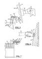
- FIGS. 2-4are side views of a lay-up tool on the end of a robot arm in several orientations to receive fiber from a stationary dispensing head.
- FIG. 5is a side view of a lay-up tool on the end of a robot arm in which the dispensing head includes limited up and down motion.
- FIG. 6is a top view of a tool on the end of a robot arm in which the dispensing head includes limited side-to-side motion.
- FIG. 7shows an alternate embodiment in which the fiber placement head is mounted directly on the creel.
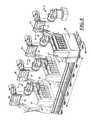
- FIG. 8shows an alternate embodiment in which several creels are mounted on a rail for motion relative to the lay-up tool.
- FIG. 1shows a robotic fiber placement cell with a stationary dispensing head and creel generally designated by the reference numeral 10 .
- the cellcomprises a creel 12 that is mounted in a fixed position on the floor.
- a fixed arm 14is mounted next to the creel 12
- a fiber placement dispensing head 15is mounted on the end of the arm 14 that is remote from the creel.
- an operator's platformmay be positioned adjacent to the creel 12
- a control panel for operating and monitoring the fiber placement cellmay be located on the operator's platform.
- the creel 12utilizes standard spool mounting and tensioning components (not shown) to control the flow of the fiber from the creel to the head 15 .
- tow material 16is routed from the creel 12 to the dispensing head 15 in a nearly straight line along the length of the arm 14 , without twisting or changing direction or length as is normally required along the tow delivery path of prior art fiber placement systems.
- the nearly straight line path for the tow material 16avoids potential damage to the tow material that can occur as a result of maneuvering the arm and the head in order to apply the tow to the tool.
- FIGS. 2-4show the tow material 16 routed along the underside of the arm 14 , but other routes such as along the sides or top of the arm, or through the interior of the arm, may be used as desired.
- Utilities 18such as electrical power and control cables, and pneumatic hoses, are easily routed along the arm 14 to the dispensing head 15 in a reliable, cost effective manner. Since the utilities 18 are stationary, the utilities routing at the head itself can be configured to optimize the available clearance between the lay-up or part tooling 20 and the dispensing head 15 . The stationary dispensing head 15 and arm 14 eliminate strain and fatigue stress on the utilities cables, hoses, and connectors of the utilities 18 since bending and flexing is eliminated.
- a robotic mechanism 25 having six degrees of freedomis mounted on a linear slide 26 at a location that is opposite to the dispensing head 15 , and is used to support the part tooling 20 that is attached to a mounting plate 22 .
- the linear slide 26is used to extend the range of the robot 25 , and other systems may use a different method for extending the range of the robotic mechanism.
- the robot 25comprises a base 27 that is capable of rotation about a vertical axis 28 .
- a first end of a lower arm 29is mounted to the base 27 by a first pivot 31 .
- a second end of the lower arm 19is coupled to an upper arm 32 by a second pivot 33 .
- a first wrist mechanism 35a rolling wrist, is provided at the end of the upper arm 32 that is remote from the second pivot 33 , and the first wrist 35 is capable of rotary motion around the longitudinal axis of the upper arm 32 .
- a second wrist mechanism 37a bending wrist, is provided on the end of the first wrist 35 , and the second wrist 37 allows pivoting motion around an axis that is that is perpendicular to the rotation of the first wrist 35 .
- a third wrist mechanism 40a rolling wrist, is provided on the end of the second wrist 37 , and the third wrist 40 allows rotation around an axis that is perpendicular to the pivoting axis of the second wrist 37 .
- the robot 25that is shown is a standard industrial robot having six degrees of freedom, although robots having other degrees of freedom and other arrangements of arms and wrists may be used as desired.
- the robot 25manipulates the lay-up tooling 20 relative to the dispensing head 15 to lay up the fiber tow 14 at the proper speed and angular orientation.
- FIG. 2shows the robot 25 holding the lay-up tooling 20 in a position so that the head is opposite a center portion 21 of the tool that has a surface that is parallel to the mounting plate 22 .
- FIG. 3shows the robot 25 holding the tooling 20 in a position so that the dispensing head 15 is opposite a lower portion 23 of the tool that has a surface that is inclined in one direction relative to the mounting plate 22 .
- the robot 25holding the tooling 20 in a position so that the dispensing head 15 is opposite an upper portion of the tool 24 that has a surface that is inclined in a different direction relative to the mounting plate 22 than the inclination of the lower portion 23 of the tool.
- the robot 25is able to cause relative movement between the dispensing head 15 and the lay-up tool 20 during application of composite fiber to the lay-up tool so that composite fiber may be applied to the lay-up tool in the desired pattern and orientation while the path length for the composite fiber between the creel 12 and the dispensing head 15 remains relatively constant.
- the robot base 27is mounted on a linear slide 26 , and the slide is of sufficient length to permit the robot to carry the lay-up tooling 20 to other work stations which are provided with additional creel and dispensing head systems.
- the creel located at station 40may provide fiber that is used for the base layers of a part
- the creel located at station 42may provide fiber that is used for the intermediate layers of a part
- the creel located at station 44may provide fiber that is used for the outer layers of a part.
- Allowing the robot 25 with the tooling 20 to travel from the first station 40 to the second station 42 and from the second station 42 to the third station 44allows the tooling to receive different fiber blends at the different stations, and takes the place of changing heads with conventional fiber placement systems in order to apply alternate materials to the part tooling 20 . Allowing the robot 25 with the tooling 20 to travel from station to station also allows the fiber that is being delivered to the tool to be changed without providing complex docking mechanisms for multiple heads that carry distinct fiber supplies that are applied to the tool. Moving the robot 25 from one station to another also permits production to continue at one station while material loading, repair, and/or maintenance operations are performed at one or more idle stations.
- the dispensing head 15is not fixed on the end of the arm 14 , but is provided with two degrees of freedom.
- FIG. 5shows the dispensing head 15 provided with a horizontal pivot axis 46 that allows the head to change its pitch, that is, to tilt up and down relative to the horizontal axis.
- the dispensing head 15 shown in solid in FIG. 5has been tilted downward so that it is at the proper angle to apply fiber to the lower part 23 of the tool.
- the head 15 shown in phantom in FIG. 5is facing straight ahead, so that the axis of the head from the front to the back of the head is horizontal.
- FIG. 6shows the dispensing head 15 provided with a vertical pivot axis 48 that allows the head to roll, that is, to move from side to side about the vertical axis 48 .
- the dispensing head 15is tilted to the side to apply fiber to the angled part 49 of the lay-up tool.
- the head shown 15 in phantom in FIG. 6is facing straight ahead, with the axis from the front to the back of the head in alignment with the longitudinal axis of the arm 14 .
- Providing the head with two degrees of motion about the horizontal axis 46 and the vertical axis 48allows the head to follow the contour of the tool more quickly, since both the head and the tool are able to change orientation to correctly position the head for the application of fiber to the tool 20 .
- the motion of the headis limited to two degrees of freedom, the change in the tow path length and direction from the arm 14 to the head 15 is minimized, and the amount of slack and free play in the utilities 18 are also greatly reduced when compared to a head that is designed to apply fiber to a stationary tool.
- the additional degree of freedom in the fiber placement headalso permits the part programmer to balance the available clearance between the systems on the head and the contours of the layup tool surface, thus enabling layup of more extreme surface irregularities.
- FIG. 7shows an alternate embodiment in which the arm 14 as shown in FIGS. 1-4 may be eliminated completely, and the dispensing head 15 may be mounted directly onto the creel 12 .
- FIG. 8shows an alternate embodiment in which one or more robots 25 , 55 , 65 , and 75 are fixed, and several creels 40 , 42 , 44 and 45 with fixed heads are mounted on a rail 80 for movement relative to the robots.
- a first creel 40 and dispensing head 15are moved into position opposite the first robot 25 in order to apply fiber from the head 15 attached to the first creel 40 to the lay-up tool 20
- a second creel 42 and head 82are moved into position opposite the first robot 25 and the lay-up tool 20 in order to apply fiber from the head attached to the second creel 42 to the lay-up tool 20 .
- any of the creels 40 , 42 , 44 and 45may be moved into position in front of the robots 25 , 55 , 65 , and 75 for the purpose of applying fibers from the creels 40 , 42 , 44 and 45 to any of the lay-up tools 20 , 86 , 88 , or 90 as desired.
Landscapes
- Engineering & Computer Science (AREA)
- Robotics (AREA)
- Chemical & Material Sciences (AREA)
- Composite Materials (AREA)
- Mechanical Engineering (AREA)
- Moulding By Coating Moulds (AREA)
- Manipulator (AREA)
Abstract
Description
Claims (15)
Priority Applications (3)
| Application Number | Priority Date | Filing Date | Title |
|---|---|---|---|
| US12/778,462US8758538B2 (en) | 2010-05-12 | 2010-05-12 | Robotic based fiber placement cell with stationary dispensing head and creel |
| ES11165497TES2406261T3 (en) | 2010-05-12 | 2011-05-10 | Robotic base fiber placement cell with stationary dispensing head and fillet |
| EP11165497AEP2402147B1 (en) | 2010-05-12 | 2011-05-10 | Robotic based fiber placement cell with stationary dispensing head and creel |
Applications Claiming Priority (1)
| Application Number | Priority Date | Filing Date | Title |
|---|---|---|---|
| US12/778,462US8758538B2 (en) | 2010-05-12 | 2010-05-12 | Robotic based fiber placement cell with stationary dispensing head and creel |
Publications (2)
| Publication Number | Publication Date |
|---|---|
| US20110277935A1 US20110277935A1 (en) | 2011-11-17 |
| US8758538B2true US8758538B2 (en) | 2014-06-24 |
Family
ID=44678101
Family Applications (1)
| Application Number | Title | Priority Date | Filing Date |
|---|---|---|---|
| US12/778,462Active2031-11-23US8758538B2 (en) | 2010-05-12 | 2010-05-12 | Robotic based fiber placement cell with stationary dispensing head and creel |
Country Status (3)
| Country | Link |
|---|---|
| US (1) | US8758538B2 (en) |
| EP (1) | EP2402147B1 (en) |
| ES (1) | ES2406261T3 (en) |
Cited By (12)
| Publication number | Priority date | Publication date | Assignee | Title |
|---|---|---|---|---|
| US9623611B2 (en) | 2014-03-21 | 2017-04-18 | Ingersoll Machine Tools, Inc. | Flexible fiber placement system for small composite parts manufacturing and methods |
| US10814570B2 (en) | 2018-11-01 | 2020-10-27 | The Boeing Company | Self-threading lamination head and method |
| US10926492B2 (en) | 2018-11-01 | 2021-02-23 | The Boeing Company | Bi-directional lamination head and method |
| US10960615B2 (en) | 2018-11-13 | 2021-03-30 | The Boeing Company | System and method for laminating a composite laminate along a continuous loop lamination path |
| US10994502B2 (en) | 2018-11-01 | 2021-05-04 | The Boeing Company | Lamination system and method using a plurality of static lamination heads |
| US11052454B2 (en) | 2019-07-23 | 2021-07-06 | The Boeing Company | Dynamic collar swage conformance checking based on swage tool parameters |
| US11059235B2 (en) | 2018-09-28 | 2021-07-13 | The Boeing Company | Reconfigurable manufacturing system and method for manufacturing composite laminates |
| US11148373B2 (en) | 2019-07-01 | 2021-10-19 | The Boeing Company | System and method for laying up a composite laminate having integrally laminated filler elements |
| US11396143B2 (en) | 2019-06-21 | 2022-07-26 | The Boeing Company | System and method for manufacturing a composite assembly |
| US11660831B2 (en) | 2020-12-04 | 2023-05-30 | Ths Boeing Company | Lamination head having bi-directional capability |
| US20230202127A1 (en)* | 2020-05-26 | 2023-06-29 | Lm Wind Power A/S | System and method for manufacturing a composite structure |
| US11780182B2 (en) | 2020-12-04 | 2023-10-10 | The Boeing Company | Lamination head having self-threading capability |
Families Citing this family (18)
| Publication number | Priority date | Publication date | Assignee | Title |
|---|---|---|---|---|
| DE102010010686A1 (en) | 2009-03-19 | 2011-01-05 | Fraunhofer-Gesellschaft zur Förderung der angewandten Forschung e.V. | Method and device for the adhesive joining of large components in vehicle construction |
| DE102010010685A1 (en)* | 2009-03-19 | 2011-02-03 | Airbus Operations Gmbh | Method for tolerance-adapted adhesive application in vehicle construction |
| US20120152432A1 (en)* | 2010-12-15 | 2012-06-21 | Samuel Francis Pedigo | Methods and systems for fiber placement using a stationary dispenser |
| US8919410B2 (en)* | 2012-03-08 | 2014-12-30 | Fives Machining Systems, Inc. | Small flat composite placement system |
| US20140065312A1 (en)* | 2012-08-30 | 2014-03-06 | General Electric Company | Inline resin-infused fiber placement systems and methods |
| EP2808158A1 (en)* | 2013-05-31 | 2014-12-03 | Siemens Aktiengesellschaft | A method and apparatus for laying a fibre material on a mould surface |
| DE102014201060A1 (en)* | 2014-01-22 | 2015-07-23 | Broetje-Automation Gmbh | Fiber laying machine and method for the production of fiber layers |
| US9399338B1 (en) | 2014-03-11 | 2016-07-26 | The Boeing Company | Systems and methods for constructing complex composite structures |
| GB2542030A (en)* | 2014-03-28 | 2017-03-08 | Composite Cluster Singapore Pte Ltd | Freespace composite manufacturing process and device |
| US10059067B2 (en)* | 2016-01-18 | 2018-08-28 | Fives Machining Systems, Inc. | Small 4-axis fiber placement machine |
| JP7171464B2 (en)* | 2019-01-31 | 2022-11-15 | 三菱重工業株式会社 | Molding device and molding method |
| EP4041536A4 (en)* | 2019-10-07 | 2024-02-14 | Fives Machining Systems, Inc. | W-axis fiber placement head |
| US12076944B2 (en) | 2020-11-18 | 2024-09-03 | The Boeing Company | Continuously moving line for making composite laminate parts |
| EP4000888B1 (en)* | 2020-11-18 | 2024-04-10 | The Boeing Company | Continuously moving line for making composite laminate parts |
| NL2027436B1 (en)* | 2021-01-26 | 2022-08-19 | Boeing Co | Continuously moving line for making composite laminate parts |
| EP4001549A1 (en)* | 2020-11-19 | 2022-05-25 | The Boeing Company | Continuous-line manufacturing system and method for composite parts |
| CN115476528B (en)* | 2022-09-05 | 2024-04-30 | 武汉大学 | Composite material wire laying robot and wire laying method based on double-arm cooperation |
| FR3141877B1 (en)* | 2022-11-15 | 2024-10-04 | Coriolis Group | FIBER PLACEMENT MACHINE |
Citations (25)
| Publication number | Priority date | Publication date | Assignee | Title |
|---|---|---|---|---|
| US3140058A (en) | 1960-06-23 | 1964-07-07 | Bendix Corp | Machine for forming laminations |
| US3309185A (en) | 1962-09-10 | 1967-03-14 | American Air Filter Co | Method for making filamentous mats |
| US3574040A (en) | 1967-06-29 | 1971-04-06 | Gen Dynamics Corp | Apparatus for making laminated structural shapes by the controlled detrusive placement and polymerization of tectonic filamentous tapes |
| US3810805A (en) | 1972-04-14 | 1974-05-14 | Goldsworthy Eng Inc | Geodesic path length compensator for composite-tape placement head |
| US3963185A (en) | 1971-12-14 | 1976-06-15 | Hills-Mccanna Company | Filament winding method |
| US4292108A (en) | 1979-12-10 | 1981-09-29 | General Dynamics Corporation | Composite tape laying apparatus including means for plural longitudinal and transverse cuts |
| US4437616A (en) | 1981-09-08 | 1984-03-20 | Ameron, Inc. | Winding fiber reinforced pipe fittings |
| GB2147561A (en)* | 1983-10-21 | 1985-05-15 | Atomic Energy Authority Uk | Filament winding |
| FR2579130A1 (en)* | 1985-03-25 | 1986-09-26 | Aerospatiale | METHOD AND DEVICE FOR MAKING A HOLLOW PIECE OF COMPLEX SHAPE BY FILAMENTARY WINDING TO CONTACT |
| US5022952A (en) | 1985-12-13 | 1991-06-11 | Cincinnati Milacron Inc. | Fiber placement machine |
| US5273602A (en) | 1990-12-19 | 1993-12-28 | Hercules Incorporated | Ribbonizing method for selectively heating a respective one of a plurality of fiber tows |
| US6096164A (en) | 1990-12-19 | 2000-08-01 | Alliant Techsystems Inc. | Multiple axes fiber placement machine |
| US6107220A (en) | 1996-10-18 | 2000-08-22 | E. I. Du Pont De Nemours And Company | Rapid fabric forming |
| US20050236735A1 (en)* | 2004-04-21 | 2005-10-27 | Ingersoll Machine Tools, Inc. | Forming a composite structure by filament placement on a tool surface of a tablet |
| US20050247396A1 (en)* | 2004-04-21 | 2005-11-10 | Ingersoll Machine Tools, Inc. | Automated fiber placement using multiple placement heads, replaceable creels, and replaceable placement heads |
| US7137182B2 (en) | 2002-11-22 | 2006-11-21 | The Boeing Company | Parallel configuration composite material fabricator |
| US20070029030A1 (en)* | 2005-08-04 | 2007-02-08 | The Boeing Company | Tow width adaptable placement head device and method |
| US20070044919A1 (en)* | 2005-08-25 | 2007-03-01 | Ingersoll Machine Tools, Inc. | Compact fiber placement apparatus and method of making and using same |
| US7282107B2 (en) | 2003-08-22 | 2007-10-16 | The Boeing Company | Multiple head automated composite laminating machine for the fabrication of large barrel section components |
| US7404868B2 (en) | 2006-10-10 | 2008-07-29 | Accudyne Systems, Inc. | Tape placement head for applying thermoplastic tape to an object |
| US7472736B2 (en)* | 2005-02-14 | 2009-01-06 | The Boeing Company | Modular head lamination device and method |
| US20090095410A1 (en)* | 2007-10-16 | 2009-04-16 | Ingersoll Machine Tools, Inc. | Fiber Placement Machine Platform System Having Interchangeable Head and Creel Assemblies |
| US20090101277A1 (en) | 2007-09-26 | 2009-04-23 | Fiberforge Corporation | System and method for the rapid, automated creation of advanced composite tailored blanks |
| WO2009062749A1 (en) | 2007-11-15 | 2009-05-22 | Airbus Deutschland Gmbh | Method and device for producing a fiber composite component |
| US20100200168A1 (en)* | 2009-02-06 | 2010-08-12 | Ingersoll Machine Tools, Inc. | Fiber delivery apparatus and system having a creel and fiber placement head sans fiber redirect |
- 2010
- 2010-05-12USUS12/778,462patent/US8758538B2/enactiveActive
- 2011
- 2011-05-10EPEP11165497Apatent/EP2402147B1/enactiveActive
- 2011-05-10ESES11165497Tpatent/ES2406261T3/enactiveActive
Patent Citations (25)
| Publication number | Priority date | Publication date | Assignee | Title |
|---|---|---|---|---|
| US3140058A (en) | 1960-06-23 | 1964-07-07 | Bendix Corp | Machine for forming laminations |
| US3309185A (en) | 1962-09-10 | 1967-03-14 | American Air Filter Co | Method for making filamentous mats |
| US3574040A (en) | 1967-06-29 | 1971-04-06 | Gen Dynamics Corp | Apparatus for making laminated structural shapes by the controlled detrusive placement and polymerization of tectonic filamentous tapes |
| US3963185A (en) | 1971-12-14 | 1976-06-15 | Hills-Mccanna Company | Filament winding method |
| US3810805A (en) | 1972-04-14 | 1974-05-14 | Goldsworthy Eng Inc | Geodesic path length compensator for composite-tape placement head |
| US4292108A (en) | 1979-12-10 | 1981-09-29 | General Dynamics Corporation | Composite tape laying apparatus including means for plural longitudinal and transverse cuts |
| US4437616A (en) | 1981-09-08 | 1984-03-20 | Ameron, Inc. | Winding fiber reinforced pipe fittings |
| GB2147561A (en)* | 1983-10-21 | 1985-05-15 | Atomic Energy Authority Uk | Filament winding |
| FR2579130A1 (en)* | 1985-03-25 | 1986-09-26 | Aerospatiale | METHOD AND DEVICE FOR MAKING A HOLLOW PIECE OF COMPLEX SHAPE BY FILAMENTARY WINDING TO CONTACT |
| US5022952A (en) | 1985-12-13 | 1991-06-11 | Cincinnati Milacron Inc. | Fiber placement machine |
| US5273602A (en) | 1990-12-19 | 1993-12-28 | Hercules Incorporated | Ribbonizing method for selectively heating a respective one of a plurality of fiber tows |
| US6096164A (en) | 1990-12-19 | 2000-08-01 | Alliant Techsystems Inc. | Multiple axes fiber placement machine |
| US6107220A (en) | 1996-10-18 | 2000-08-22 | E. I. Du Pont De Nemours And Company | Rapid fabric forming |
| US7137182B2 (en) | 2002-11-22 | 2006-11-21 | The Boeing Company | Parallel configuration composite material fabricator |
| US7282107B2 (en) | 2003-08-22 | 2007-10-16 | The Boeing Company | Multiple head automated composite laminating machine for the fabrication of large barrel section components |
| US20050236735A1 (en)* | 2004-04-21 | 2005-10-27 | Ingersoll Machine Tools, Inc. | Forming a composite structure by filament placement on a tool surface of a tablet |
| US20050247396A1 (en)* | 2004-04-21 | 2005-11-10 | Ingersoll Machine Tools, Inc. | Automated fiber placement using multiple placement heads, replaceable creels, and replaceable placement heads |
| US7472736B2 (en)* | 2005-02-14 | 2009-01-06 | The Boeing Company | Modular head lamination device and method |
| US20070029030A1 (en)* | 2005-08-04 | 2007-02-08 | The Boeing Company | Tow width adaptable placement head device and method |
| US20070044919A1 (en)* | 2005-08-25 | 2007-03-01 | Ingersoll Machine Tools, Inc. | Compact fiber placement apparatus and method of making and using same |
| US7404868B2 (en) | 2006-10-10 | 2008-07-29 | Accudyne Systems, Inc. | Tape placement head for applying thermoplastic tape to an object |
| US20090101277A1 (en) | 2007-09-26 | 2009-04-23 | Fiberforge Corporation | System and method for the rapid, automated creation of advanced composite tailored blanks |
| US20090095410A1 (en)* | 2007-10-16 | 2009-04-16 | Ingersoll Machine Tools, Inc. | Fiber Placement Machine Platform System Having Interchangeable Head and Creel Assemblies |
| WO2009062749A1 (en) | 2007-11-15 | 2009-05-22 | Airbus Deutschland Gmbh | Method and device for producing a fiber composite component |
| US20100200168A1 (en)* | 2009-02-06 | 2010-08-12 | Ingersoll Machine Tools, Inc. | Fiber delivery apparatus and system having a creel and fiber placement head sans fiber redirect |
Non-Patent Citations (4)
| Title |
|---|
| "Coriolis composites a la fibre robot", Plastiques & Caoutchoucs Magazine, Apr. 2007, one page.* |
| Ermert, et al, "R U Reinforcing plastics with robots?" Plastics Engineering, May 1981, pp. 37-46.* |
| European Search Report; EP 11 16 5497; dated Nov. 21, 2011; 4 pages. |
| Translation of French Patent 2579130, date unknown.* |
Cited By (12)
| Publication number | Priority date | Publication date | Assignee | Title |
|---|---|---|---|---|
| US9623611B2 (en) | 2014-03-21 | 2017-04-18 | Ingersoll Machine Tools, Inc. | Flexible fiber placement system for small composite parts manufacturing and methods |
| US11059235B2 (en) | 2018-09-28 | 2021-07-13 | The Boeing Company | Reconfigurable manufacturing system and method for manufacturing composite laminates |
| US10814570B2 (en) | 2018-11-01 | 2020-10-27 | The Boeing Company | Self-threading lamination head and method |
| US10926492B2 (en) | 2018-11-01 | 2021-02-23 | The Boeing Company | Bi-directional lamination head and method |
| US10994502B2 (en) | 2018-11-01 | 2021-05-04 | The Boeing Company | Lamination system and method using a plurality of static lamination heads |
| US10960615B2 (en) | 2018-11-13 | 2021-03-30 | The Boeing Company | System and method for laminating a composite laminate along a continuous loop lamination path |
| US11396143B2 (en) | 2019-06-21 | 2022-07-26 | The Boeing Company | System and method for manufacturing a composite assembly |
| US11148373B2 (en) | 2019-07-01 | 2021-10-19 | The Boeing Company | System and method for laying up a composite laminate having integrally laminated filler elements |
| US11052454B2 (en) | 2019-07-23 | 2021-07-06 | The Boeing Company | Dynamic collar swage conformance checking based on swage tool parameters |
| US20230202127A1 (en)* | 2020-05-26 | 2023-06-29 | Lm Wind Power A/S | System and method for manufacturing a composite structure |
| US11660831B2 (en) | 2020-12-04 | 2023-05-30 | Ths Boeing Company | Lamination head having bi-directional capability |
| US11780182B2 (en) | 2020-12-04 | 2023-10-10 | The Boeing Company | Lamination head having self-threading capability |
Also Published As
| Publication number | Publication date |
|---|---|
| ES2406261T3 (en) | 2013-06-06 |
| EP2402147A1 (en) | 2012-01-04 |
| US20110277935A1 (en) | 2011-11-17 |
| EP2402147B1 (en) | 2013-03-27 |
Similar Documents
| Publication | Publication Date | Title |
|---|---|---|
| US8758538B2 (en) | Robotic based fiber placement cell with stationary dispensing head and creel | |
| EP1719610B1 (en) | Fibre placement machine | |
| US8919410B2 (en) | Small flat composite placement system | |
| US8210418B1 (en) | Multi-station, gantry-based automated welding system | |
| EP3071398B1 (en) | A laying device and a method for the laying down of fibre tapes | |
| US4877193A (en) | Redirect roller apparatus for fiber placement machine | |
| US8919409B2 (en) | Dockable cut clamp and restart mechanism for a fiber placement head | |
| US20100200168A1 (en) | Fiber delivery apparatus and system having a creel and fiber placement head sans fiber redirect | |
| EP2305456B1 (en) | A multi-axis robotic wrist and fiber placement apparatus incorporating same and related method | |
| JP7050502B2 (en) | Cable carrier crossover that supplies four unsteady positions | |
| US20240343001A1 (en) | Filament winding machine with a rotating support having a plurality of winding heads | |
| JP2018512303A (en) | Fiber laying machine and method for laying fiber web on workpiece | |
| CN108356777B (en) | Belt-driven double-robot portal frame | |
| JP2018511493A (en) | System for manufacturing fiber composite members | |
| EP0355308B1 (en) | Fibre placement machine | |
| JP6962118B2 (en) | Work transfer device | |
| US7516944B2 (en) | Swiveling and tilting roller axis for web guiding in a fiber placement machine | |
| JP6991868B2 (en) | Separate human work platform for stable positioning of collaborative robotics | |
| EP3354413A1 (en) | Isolated human work platform for stabilized positioning of collaborative robotics | |
| CN120364419A (en) | Automatic conveying equipment for feeding and discharging in optical fiber preform production process | |
| JPH10207549A (en) | Device for positioning pipe and flange |
Legal Events
| Date | Code | Title | Description |
|---|---|---|---|
| AS | Assignment | Owner name:CINCINNATI MACHINE, LLC, KENTUCKY Free format text:ASSIGNMENT OF ASSIGNORS INTEREST;ASSIGNORS:BORGMANN, ROBERT E.;ALBERS, STEPHEN J.;KNEIFEL, R. WILLIAM, II;REEL/FRAME:024378/0178 Effective date:20100506 | |
| AS | Assignment | Owner name:MAG IAS, LLC, A DELAWARE LIMITED LIABILITY COMPANY Free format text:ASSIGNMENT OF ASSIGNORS INTEREST;ASSIGNOR:CINCINNATI MACHINE, LLC;REEL/FRAME:025586/0666 Effective date:20101221 | |
| AS | Assignment | Owner name:WELLS FARGO BANK, NATIONAL ASSOCIATION, ILLINOIS Free format text:ASSIGNMENT OF ASSIGNORS INTEREST;ASSIGNOR:BURDALE CAPITAL FINANCE, INC.;REEL/FRAME:028794/0724 Effective date:20120711 | |
| AS | Assignment | Owner name:WELLS FARGO BANK, NATIONAL ASSOCIATION, ILLINOIS Free format text:SECURITY AGREEMENT;ASSIGNOR:MAG IAS, LLC;REEL/FRAME:031501/0920 Effective date:20130729 | |
| AS | Assignment | Owner name:FIVES MACHINING SYSTEMS, INC., WISCONSIN Free format text:CHANGE OF NAME;ASSIGNOR:MAG IAS, LLC;REEL/FRAME:031481/0448 Effective date:20130729 | |
| AS | Assignment | Owner name:CINCINNATI MACHINE, LLC, KENTUCKY Free format text:RELEASE OF SECURITY INTEREST;ASSIGNOR:WELLS FARGO BANK, NATIONAL ASSOCIATIION;REEL/FRAME:032190/0942 Effective date:20130729 | |
| STCF | Information on status: patent grant | Free format text:PATENTED CASE | |
| MAFP | Maintenance fee payment | Free format text:PAYMENT OF MAINTENANCE FEE, 4TH YEAR, LARGE ENTITY (ORIGINAL EVENT CODE: M1551) Year of fee payment:4 | |
| MAFP | Maintenance fee payment | Free format text:PAYMENT OF MAINTENANCE FEE, 8TH YEAR, LARGE ENTITY (ORIGINAL EVENT CODE: M1552); ENTITY STATUS OF PATENT OWNER: LARGE ENTITY Year of fee payment:8 |