US8758446B2 - Method and apparatus for protecting modular implant connection - Google Patents
Method and apparatus for protecting modular implant connectionDownload PDFInfo
- Publication number
- US8758446B2 US8758446B2US12/409,015US40901509AUS8758446B2US 8758446 B2US8758446 B2US 8758446B2US 40901509 AUS40901509 AUS 40901509AUS 8758446 B2US8758446 B2US 8758446B2
- Authority
- US
- United States
- Prior art keywords
- guard
- modular implant
- reaming
- bone
- connection portion
- Prior art date
- Legal status (The legal status is an assumption and is not a legal conclusion. Google has not performed a legal analysis and makes no representation as to the accuracy of the status listed.)
- Active, expires
Links
- 239000007943implantSubstances0.000titleclaimsabstractdescription38
- 238000000034methodMethods0.000titleclaimsabstractdescription23
- 210000000988bone and boneAnatomy0.000claimsdescription25
- 210000003484anatomyAnatomy0.000claimsdescription2
- 210000001519tissueAnatomy0.000claims4
- 238000012360testing methodMethods0.000description3
- 239000002639bone cementSubstances0.000description2
- 230000006378damageEffects0.000description2
- 208000014674injuryDiseases0.000description2
- 239000004696Poly ether ether ketoneSubstances0.000description1
- 239000004698PolyethyleneSubstances0.000description1
- 208000027418Wounds and injuryDiseases0.000description1
- JUPQTSLXMOCDHR-UHFFFAOYSA-Nbenzene-1,4-diol;bis(4-fluorophenyl)methanoneChemical compoundOC1=CC=C(O)C=C1.C1=CC(F)=CC=C1C(=O)C1=CC=C(F)C=C1JUPQTSLXMOCDHR-UHFFFAOYSA-N0.000description1
- 229920000249biocompatible polymerPolymers0.000description1
- 230000007423decreaseEffects0.000description1
- 201000010099diseaseDiseases0.000description1
- 208000037265diseases, disorders, signs and symptomsDiseases0.000description1
- 238000003780insertionMethods0.000description1
- 230000037431insertionEffects0.000description1
- 230000003993interactionEffects0.000description1
- 230000013011matingEffects0.000description1
- 238000005259measurementMethods0.000description1
- 238000012986modificationMethods0.000description1
- 230000004048modificationEffects0.000description1
- 229920002530polyetherether ketonePolymers0.000description1
- -1polyethylenePolymers0.000description1
- 229920000573polyethylenePolymers0.000description1
- 238000006748scratchingMethods0.000description1
- 230000002393scratching effectEffects0.000description1
- 238000001356surgical procedureMethods0.000description1
- 230000008733traumaEffects0.000description1
Images


Classifications
- A—HUMAN NECESSITIES
- A61—MEDICAL OR VETERINARY SCIENCE; HYGIENE
- A61F—FILTERS IMPLANTABLE INTO BLOOD VESSELS; PROSTHESES; DEVICES PROVIDING PATENCY TO, OR PREVENTING COLLAPSING OF, TUBULAR STRUCTURES OF THE BODY, e.g. STENTS; ORTHOPAEDIC, NURSING OR CONTRACEPTIVE DEVICES; FOMENTATION; TREATMENT OR PROTECTION OF EYES OR EARS; BANDAGES, DRESSINGS OR ABSORBENT PADS; FIRST-AID KITS
- A61F2/00—Filters implantable into blood vessels; Prostheses, i.e. artificial substitutes or replacements for parts of the body; Appliances for connecting them with the body; Devices providing patency to, or preventing collapsing of, tubular structures of the body, e.g. stents
- A61F2/02—Prostheses implantable into the body
- A61F2/30—Joints
- A61F2/32—Joints for the hip
- A61F2/36—Femoral heads ; Femoral endoprostheses
- A—HUMAN NECESSITIES
- A61—MEDICAL OR VETERINARY SCIENCE; HYGIENE
- A61B—DIAGNOSIS; SURGERY; IDENTIFICATION
- A61B17/00—Surgical instruments, devices or methods
- A61B17/16—Instruments for performing osteoclasis; Drills or chisels for bones; Trepans
- A61B17/1662—Instruments for performing osteoclasis; Drills or chisels for bones; Trepans for particular parts of the body
- A61B17/1664—Instruments for performing osteoclasis; Drills or chisels for bones; Trepans for particular parts of the body for the hip
- A61B17/1668—Instruments for performing osteoclasis; Drills or chisels for bones; Trepans for particular parts of the body for the hip for the upper femur
- A—HUMAN NECESSITIES
- A61—MEDICAL OR VETERINARY SCIENCE; HYGIENE
- A61F—FILTERS IMPLANTABLE INTO BLOOD VESSELS; PROSTHESES; DEVICES PROVIDING PATENCY TO, OR PREVENTING COLLAPSING OF, TUBULAR STRUCTURES OF THE BODY, e.g. STENTS; ORTHOPAEDIC, NURSING OR CONTRACEPTIVE DEVICES; FOMENTATION; TREATMENT OR PROTECTION OF EYES OR EARS; BANDAGES, DRESSINGS OR ABSORBENT PADS; FIRST-AID KITS
- A61F2/00—Filters implantable into blood vessels; Prostheses, i.e. artificial substitutes or replacements for parts of the body; Appliances for connecting them with the body; Devices providing patency to, or preventing collapsing of, tubular structures of the body, e.g. stents
- A61F2/02—Prostheses implantable into the body
- A61F2/30—Joints
- A61F2/32—Joints for the hip
- A61F2/36—Femoral heads ; Femoral endoprostheses
- A61F2/3607—Femoral heads ; Femoral endoprostheses including proximal or total replacement of the femur
- A—HUMAN NECESSITIES
- A61—MEDICAL OR VETERINARY SCIENCE; HYGIENE
- A61F—FILTERS IMPLANTABLE INTO BLOOD VESSELS; PROSTHESES; DEVICES PROVIDING PATENCY TO, OR PREVENTING COLLAPSING OF, TUBULAR STRUCTURES OF THE BODY, e.g. STENTS; ORTHOPAEDIC, NURSING OR CONTRACEPTIVE DEVICES; FOMENTATION; TREATMENT OR PROTECTION OF EYES OR EARS; BANDAGES, DRESSINGS OR ABSORBENT PADS; FIRST-AID KITS
- A61F2/00—Filters implantable into blood vessels; Prostheses, i.e. artificial substitutes or replacements for parts of the body; Appliances for connecting them with the body; Devices providing patency to, or preventing collapsing of, tubular structures of the body, e.g. stents
- A61F2/02—Prostheses implantable into the body
- A61F2/30—Joints
- A61F2/46—Special tools for implanting artificial joints
- A61F2/4603—Special tools for implanting artificial joints for insertion or extraction of endoprosthetic joints or of accessories thereof
- A61F2/4607—Special tools for implanting artificial joints for insertion or extraction of endoprosthetic joints or of accessories thereof of hip femoral endoprostheses
- A—HUMAN NECESSITIES
- A61—MEDICAL OR VETERINARY SCIENCE; HYGIENE
- A61F—FILTERS IMPLANTABLE INTO BLOOD VESSELS; PROSTHESES; DEVICES PROVIDING PATENCY TO, OR PREVENTING COLLAPSING OF, TUBULAR STRUCTURES OF THE BODY, e.g. STENTS; ORTHOPAEDIC, NURSING OR CONTRACEPTIVE DEVICES; FOMENTATION; TREATMENT OR PROTECTION OF EYES OR EARS; BANDAGES, DRESSINGS OR ABSORBENT PADS; FIRST-AID KITS
- A61F2/00—Filters implantable into blood vessels; Prostheses, i.e. artificial substitutes or replacements for parts of the body; Appliances for connecting them with the body; Devices providing patency to, or preventing collapsing of, tubular structures of the body, e.g. stents
- A61F2/02—Prostheses implantable into the body
- A61F2/30—Joints
- A61F2/46—Special tools for implanting artificial joints
- A61F2/4637—Special tools for implanting artificial joints for connecting or disconnecting two parts of a prosthesis
- A—HUMAN NECESSITIES
- A61—MEDICAL OR VETERINARY SCIENCE; HYGIENE
- A61F—FILTERS IMPLANTABLE INTO BLOOD VESSELS; PROSTHESES; DEVICES PROVIDING PATENCY TO, OR PREVENTING COLLAPSING OF, TUBULAR STRUCTURES OF THE BODY, e.g. STENTS; ORTHOPAEDIC, NURSING OR CONTRACEPTIVE DEVICES; FOMENTATION; TREATMENT OR PROTECTION OF EYES OR EARS; BANDAGES, DRESSINGS OR ABSORBENT PADS; FIRST-AID KITS
- A61F2/00—Filters implantable into blood vessels; Prostheses, i.e. artificial substitutes or replacements for parts of the body; Appliances for connecting them with the body; Devices providing patency to, or preventing collapsing of, tubular structures of the body, e.g. stents
- A61F2/02—Prostheses implantable into the body
- A61F2/30—Joints
- A61F2/46—Special tools for implanting artificial joints
- A61F2/4684—Trial or dummy prostheses
- A—HUMAN NECESSITIES
- A61—MEDICAL OR VETERINARY SCIENCE; HYGIENE
- A61B—DIAGNOSIS; SURGERY; IDENTIFICATION
- A61B17/00—Surgical instruments, devices or methods
- A61B17/16—Instruments for performing osteoclasis; Drills or chisels for bones; Trepans
- A61B17/17—Guides or aligning means for drills, mills, pins or wires
- A61B17/1739—Guides or aligning means for drills, mills, pins or wires specially adapted for particular parts of the body
- A61B17/1742—Guides or aligning means for drills, mills, pins or wires specially adapted for particular parts of the body for the hip
- A61B17/175—Guides or aligning means for drills, mills, pins or wires specially adapted for particular parts of the body for the hip for preparing the femur for hip prosthesis insertion
- A—HUMAN NECESSITIES
- A61—MEDICAL OR VETERINARY SCIENCE; HYGIENE
- A61F—FILTERS IMPLANTABLE INTO BLOOD VESSELS; PROSTHESES; DEVICES PROVIDING PATENCY TO, OR PREVENTING COLLAPSING OF, TUBULAR STRUCTURES OF THE BODY, e.g. STENTS; ORTHOPAEDIC, NURSING OR CONTRACEPTIVE DEVICES; FOMENTATION; TREATMENT OR PROTECTION OF EYES OR EARS; BANDAGES, DRESSINGS OR ABSORBENT PADS; FIRST-AID KITS
- A61F2/00—Filters implantable into blood vessels; Prostheses, i.e. artificial substitutes or replacements for parts of the body; Appliances for connecting them with the body; Devices providing patency to, or preventing collapsing of, tubular structures of the body, e.g. stents
- A61F2/0095—Packages or dispensers for prostheses or other implants
- A—HUMAN NECESSITIES
- A61—MEDICAL OR VETERINARY SCIENCE; HYGIENE
- A61F—FILTERS IMPLANTABLE INTO BLOOD VESSELS; PROSTHESES; DEVICES PROVIDING PATENCY TO, OR PREVENTING COLLAPSING OF, TUBULAR STRUCTURES OF THE BODY, e.g. STENTS; ORTHOPAEDIC, NURSING OR CONTRACEPTIVE DEVICES; FOMENTATION; TREATMENT OR PROTECTION OF EYES OR EARS; BANDAGES, DRESSINGS OR ABSORBENT PADS; FIRST-AID KITS
- A61F2/00—Filters implantable into blood vessels; Prostheses, i.e. artificial substitutes or replacements for parts of the body; Appliances for connecting them with the body; Devices providing patency to, or preventing collapsing of, tubular structures of the body, e.g. stents
- A61F2/02—Prostheses implantable into the body
- A61F2/30—Joints
- A61F2002/30001—Additional features of subject-matter classified in A61F2/28, A61F2/30 and subgroups thereof
- A61F2002/30316—The prosthesis having different structural features at different locations within the same prosthesis; Connections between prosthetic parts; Special structural features of bone or joint prostheses not otherwise provided for
- A61F2002/30329—Connections or couplings between prosthetic parts, e.g. between modular parts; Connecting elements
- A61F2002/30331—Connections or couplings between prosthetic parts, e.g. between modular parts; Connecting elements made by longitudinally pushing a protrusion into a complementarily-shaped recess, e.g. held by friction fit
- A61F2002/30332—Conically- or frustoconically-shaped protrusion and recess
- A—HUMAN NECESSITIES
- A61—MEDICAL OR VETERINARY SCIENCE; HYGIENE
- A61F—FILTERS IMPLANTABLE INTO BLOOD VESSELS; PROSTHESES; DEVICES PROVIDING PATENCY TO, OR PREVENTING COLLAPSING OF, TUBULAR STRUCTURES OF THE BODY, e.g. STENTS; ORTHOPAEDIC, NURSING OR CONTRACEPTIVE DEVICES; FOMENTATION; TREATMENT OR PROTECTION OF EYES OR EARS; BANDAGES, DRESSINGS OR ABSORBENT PADS; FIRST-AID KITS
- A61F2/00—Filters implantable into blood vessels; Prostheses, i.e. artificial substitutes or replacements for parts of the body; Appliances for connecting them with the body; Devices providing patency to, or preventing collapsing of, tubular structures of the body, e.g. stents
- A61F2/02—Prostheses implantable into the body
- A61F2/30—Joints
- A61F2002/30001—Additional features of subject-matter classified in A61F2/28, A61F2/30 and subgroups thereof
- A61F2002/30316—The prosthesis having different structural features at different locations within the same prosthesis; Connections between prosthetic parts; Special structural features of bone or joint prostheses not otherwise provided for
- A61F2002/30329—Connections or couplings between prosthetic parts, e.g. between modular parts; Connecting elements
- A61F2002/30331—Connections or couplings between prosthetic parts, e.g. between modular parts; Connecting elements made by longitudinally pushing a protrusion into a complementarily-shaped recess, e.g. held by friction fit
- A61F2002/30354—Cylindrically-shaped protrusion and recess, e.g. cylinder of circular basis
- A—HUMAN NECESSITIES
- A61—MEDICAL OR VETERINARY SCIENCE; HYGIENE
- A61F—FILTERS IMPLANTABLE INTO BLOOD VESSELS; PROSTHESES; DEVICES PROVIDING PATENCY TO, OR PREVENTING COLLAPSING OF, TUBULAR STRUCTURES OF THE BODY, e.g. STENTS; ORTHOPAEDIC, NURSING OR CONTRACEPTIVE DEVICES; FOMENTATION; TREATMENT OR PROTECTION OF EYES OR EARS; BANDAGES, DRESSINGS OR ABSORBENT PADS; FIRST-AID KITS
- A61F2/00—Filters implantable into blood vessels; Prostheses, i.e. artificial substitutes or replacements for parts of the body; Appliances for connecting them with the body; Devices providing patency to, or preventing collapsing of, tubular structures of the body, e.g. stents
- A61F2/02—Prostheses implantable into the body
- A61F2/30—Joints
- A61F2002/30001—Additional features of subject-matter classified in A61F2/28, A61F2/30 and subgroups thereof
- A61F2002/30316—The prosthesis having different structural features at different locations within the same prosthesis; Connections between prosthetic parts; Special structural features of bone or joint prostheses not otherwise provided for
- A61F2002/30329—Connections or couplings between prosthetic parts, e.g. between modular parts; Connecting elements
- A61F2002/30474—Connections or couplings between prosthetic parts, e.g. between modular parts; Connecting elements using an intermediate sleeve interposed between both prosthetic parts to be coupled
- A—HUMAN NECESSITIES
- A61—MEDICAL OR VETERINARY SCIENCE; HYGIENE
- A61F—FILTERS IMPLANTABLE INTO BLOOD VESSELS; PROSTHESES; DEVICES PROVIDING PATENCY TO, OR PREVENTING COLLAPSING OF, TUBULAR STRUCTURES OF THE BODY, e.g. STENTS; ORTHOPAEDIC, NURSING OR CONTRACEPTIVE DEVICES; FOMENTATION; TREATMENT OR PROTECTION OF EYES OR EARS; BANDAGES, DRESSINGS OR ABSORBENT PADS; FIRST-AID KITS
- A61F2/00—Filters implantable into blood vessels; Prostheses, i.e. artificial substitutes or replacements for parts of the body; Appliances for connecting them with the body; Devices providing patency to, or preventing collapsing of, tubular structures of the body, e.g. stents
- A61F2/02—Prostheses implantable into the body
- A61F2/30—Joints
- A61F2002/30001—Additional features of subject-matter classified in A61F2/28, A61F2/30 and subgroups thereof
- A61F2002/30316—The prosthesis having different structural features at different locations within the same prosthesis; Connections between prosthetic parts; Special structural features of bone or joint prostheses not otherwise provided for
- A61F2002/30329—Connections or couplings between prosthetic parts, e.g. between modular parts; Connecting elements
- A61F2002/30476—Connections or couplings between prosthetic parts, e.g. between modular parts; Connecting elements locked by an additional locking mechanism
- A61F2002/30507—Connections or couplings between prosthetic parts, e.g. between modular parts; Connecting elements locked by an additional locking mechanism using a threaded locking member, e.g. a locking screw or a set screw
- A—HUMAN NECESSITIES
- A61—MEDICAL OR VETERINARY SCIENCE; HYGIENE
- A61F—FILTERS IMPLANTABLE INTO BLOOD VESSELS; PROSTHESES; DEVICES PROVIDING PATENCY TO, OR PREVENTING COLLAPSING OF, TUBULAR STRUCTURES OF THE BODY, e.g. STENTS; ORTHOPAEDIC, NURSING OR CONTRACEPTIVE DEVICES; FOMENTATION; TREATMENT OR PROTECTION OF EYES OR EARS; BANDAGES, DRESSINGS OR ABSORBENT PADS; FIRST-AID KITS
- A61F2/00—Filters implantable into blood vessels; Prostheses, i.e. artificial substitutes or replacements for parts of the body; Appliances for connecting them with the body; Devices providing patency to, or preventing collapsing of, tubular structures of the body, e.g. stents
- A61F2/02—Prostheses implantable into the body
- A61F2/30—Joints
- A61F2002/30001—Additional features of subject-matter classified in A61F2/28, A61F2/30 and subgroups thereof
- A61F2002/30316—The prosthesis having different structural features at different locations within the same prosthesis; Connections between prosthetic parts; Special structural features of bone or joint prostheses not otherwise provided for
- A61F2002/30535—Special structural features of bone or joint prostheses not otherwise provided for
- A61F2002/30604—Special structural features of bone or joint prostheses not otherwise provided for modular
- A61F2002/30616—Sets comprising a plurality of prosthetic parts of different sizes or orientations
- A—HUMAN NECESSITIES
- A61—MEDICAL OR VETERINARY SCIENCE; HYGIENE
- A61F—FILTERS IMPLANTABLE INTO BLOOD VESSELS; PROSTHESES; DEVICES PROVIDING PATENCY TO, OR PREVENTING COLLAPSING OF, TUBULAR STRUCTURES OF THE BODY, e.g. STENTS; ORTHOPAEDIC, NURSING OR CONTRACEPTIVE DEVICES; FOMENTATION; TREATMENT OR PROTECTION OF EYES OR EARS; BANDAGES, DRESSINGS OR ABSORBENT PADS; FIRST-AID KITS
- A61F2/00—Filters implantable into blood vessels; Prostheses, i.e. artificial substitutes or replacements for parts of the body; Appliances for connecting them with the body; Devices providing patency to, or preventing collapsing of, tubular structures of the body, e.g. stents
- A61F2/02—Prostheses implantable into the body
- A61F2/30—Joints
- A61F2002/30001—Additional features of subject-matter classified in A61F2/28, A61F2/30 and subgroups thereof
- A61F2002/30667—Features concerning an interaction with the environment or a particular use of the prosthesis
- A61F2002/30718—Means for protecting prosthetic parts, e.g. during operation
- A—HUMAN NECESSITIES
- A61—MEDICAL OR VETERINARY SCIENCE; HYGIENE
- A61F—FILTERS IMPLANTABLE INTO BLOOD VESSELS; PROSTHESES; DEVICES PROVIDING PATENCY TO, OR PREVENTING COLLAPSING OF, TUBULAR STRUCTURES OF THE BODY, e.g. STENTS; ORTHOPAEDIC, NURSING OR CONTRACEPTIVE DEVICES; FOMENTATION; TREATMENT OR PROTECTION OF EYES OR EARS; BANDAGES, DRESSINGS OR ABSORBENT PADS; FIRST-AID KITS
- A61F2/00—Filters implantable into blood vessels; Prostheses, i.e. artificial substitutes or replacements for parts of the body; Appliances for connecting them with the body; Devices providing patency to, or preventing collapsing of, tubular structures of the body, e.g. stents
- A61F2/02—Prostheses implantable into the body
- A61F2/30—Joints
- A61F2/30767—Special external or bone-contacting surface, e.g. coating for improving bone ingrowth
- A61F2/30771—Special external or bone-contacting surface, e.g. coating for improving bone ingrowth applied in original prostheses, e.g. holes or grooves
- A61F2002/3082—Grooves
- A61F2002/30822—Circumferential grooves
- A—HUMAN NECESSITIES
- A61—MEDICAL OR VETERINARY SCIENCE; HYGIENE
- A61F—FILTERS IMPLANTABLE INTO BLOOD VESSELS; PROSTHESES; DEVICES PROVIDING PATENCY TO, OR PREVENTING COLLAPSING OF, TUBULAR STRUCTURES OF THE BODY, e.g. STENTS; ORTHOPAEDIC, NURSING OR CONTRACEPTIVE DEVICES; FOMENTATION; TREATMENT OR PROTECTION OF EYES OR EARS; BANDAGES, DRESSINGS OR ABSORBENT PADS; FIRST-AID KITS
- A61F2/00—Filters implantable into blood vessels; Prostheses, i.e. artificial substitutes or replacements for parts of the body; Appliances for connecting them with the body; Devices providing patency to, or preventing collapsing of, tubular structures of the body, e.g. stents
- A61F2/02—Prostheses implantable into the body
- A61F2/30—Joints
- A61F2/30767—Special external or bone-contacting surface, e.g. coating for improving bone ingrowth
- A61F2/30771—Special external or bone-contacting surface, e.g. coating for improving bone ingrowth applied in original prostheses, e.g. holes or grooves
- A61F2002/3082—Grooves
- A61F2002/30827—Plurality of grooves
- A61F2002/30828—Plurality of grooves parallel
- A—HUMAN NECESSITIES
- A61—MEDICAL OR VETERINARY SCIENCE; HYGIENE
- A61F—FILTERS IMPLANTABLE INTO BLOOD VESSELS; PROSTHESES; DEVICES PROVIDING PATENCY TO, OR PREVENTING COLLAPSING OF, TUBULAR STRUCTURES OF THE BODY, e.g. STENTS; ORTHOPAEDIC, NURSING OR CONTRACEPTIVE DEVICES; FOMENTATION; TREATMENT OR PROTECTION OF EYES OR EARS; BANDAGES, DRESSINGS OR ABSORBENT PADS; FIRST-AID KITS
- A61F2/00—Filters implantable into blood vessels; Prostheses, i.e. artificial substitutes or replacements for parts of the body; Appliances for connecting them with the body; Devices providing patency to, or preventing collapsing of, tubular structures of the body, e.g. stents
- A61F2/02—Prostheses implantable into the body
- A61F2/30—Joints
- A61F2/32—Joints for the hip
- A61F2/36—Femoral heads ; Femoral endoprostheses
- A61F2/3662—Femoral shafts
- A61F2/3672—Intermediate parts of shafts
- A61F2002/3674—Connections of proximal parts to distal parts
- A—HUMAN NECESSITIES
- A61—MEDICAL OR VETERINARY SCIENCE; HYGIENE
- A61F—FILTERS IMPLANTABLE INTO BLOOD VESSELS; PROSTHESES; DEVICES PROVIDING PATENCY TO, OR PREVENTING COLLAPSING OF, TUBULAR STRUCTURES OF THE BODY, e.g. STENTS; ORTHOPAEDIC, NURSING OR CONTRACEPTIVE DEVICES; FOMENTATION; TREATMENT OR PROTECTION OF EYES OR EARS; BANDAGES, DRESSINGS OR ABSORBENT PADS; FIRST-AID KITS
- A61F2/00—Filters implantable into blood vessels; Prostheses, i.e. artificial substitutes or replacements for parts of the body; Appliances for connecting them with the body; Devices providing patency to, or preventing collapsing of, tubular structures of the body, e.g. stents
- A61F2/02—Prostheses implantable into the body
- A61F2/30—Joints
- A61F2/46—Special tools for implanting artificial joints
- A61F2/4603—Special tools for implanting artificial joints for insertion or extraction of endoprosthetic joints or of accessories thereof
- A61F2002/4622—Special tools for implanting artificial joints for insertion or extraction of endoprosthetic joints or of accessories thereof having the shape of a forceps or a clamp
- A—HUMAN NECESSITIES
- A61—MEDICAL OR VETERINARY SCIENCE; HYGIENE
- A61F—FILTERS IMPLANTABLE INTO BLOOD VESSELS; PROSTHESES; DEVICES PROVIDING PATENCY TO, OR PREVENTING COLLAPSING OF, TUBULAR STRUCTURES OF THE BODY, e.g. STENTS; ORTHOPAEDIC, NURSING OR CONTRACEPTIVE DEVICES; FOMENTATION; TREATMENT OR PROTECTION OF EYES OR EARS; BANDAGES, DRESSINGS OR ABSORBENT PADS; FIRST-AID KITS
- A61F2/00—Filters implantable into blood vessels; Prostheses, i.e. artificial substitutes or replacements for parts of the body; Appliances for connecting them with the body; Devices providing patency to, or preventing collapsing of, tubular structures of the body, e.g. stents
- A61F2/02—Prostheses implantable into the body
- A61F2/30—Joints
- A61F2/46—Special tools for implanting artificial joints
- A61F2/4603—Special tools for implanting artificial joints for insertion or extraction of endoprosthetic joints or of accessories thereof
- A61F2002/4629—Special tools for implanting artificial joints for insertion or extraction of endoprosthetic joints or of accessories thereof connected to the endoprosthesis or implant via a threaded connection
- A—HUMAN NECESSITIES
- A61—MEDICAL OR VETERINARY SCIENCE; HYGIENE
- A61F—FILTERS IMPLANTABLE INTO BLOOD VESSELS; PROSTHESES; DEVICES PROVIDING PATENCY TO, OR PREVENTING COLLAPSING OF, TUBULAR STRUCTURES OF THE BODY, e.g. STENTS; ORTHOPAEDIC, NURSING OR CONTRACEPTIVE DEVICES; FOMENTATION; TREATMENT OR PROTECTION OF EYES OR EARS; BANDAGES, DRESSINGS OR ABSORBENT PADS; FIRST-AID KITS
- A61F2/00—Filters implantable into blood vessels; Prostheses, i.e. artificial substitutes or replacements for parts of the body; Appliances for connecting them with the body; Devices providing patency to, or preventing collapsing of, tubular structures of the body, e.g. stents
- A61F2/02—Prostheses implantable into the body
- A61F2/30—Joints
- A61F2/46—Special tools for implanting artificial joints
- A61F2/4637—Special tools for implanting artificial joints for connecting or disconnecting two parts of a prosthesis
- A61F2002/4641—Special tools for implanting artificial joints for connecting or disconnecting two parts of a prosthesis for disconnecting
- A—HUMAN NECESSITIES
- A61—MEDICAL OR VETERINARY SCIENCE; HYGIENE
- A61F—FILTERS IMPLANTABLE INTO BLOOD VESSELS; PROSTHESES; DEVICES PROVIDING PATENCY TO, OR PREVENTING COLLAPSING OF, TUBULAR STRUCTURES OF THE BODY, e.g. STENTS; ORTHOPAEDIC, NURSING OR CONTRACEPTIVE DEVICES; FOMENTATION; TREATMENT OR PROTECTION OF EYES OR EARS; BANDAGES, DRESSINGS OR ABSORBENT PADS; FIRST-AID KITS
- A61F2220/00—Fixations or connections for prostheses classified in groups A61F2/00 - A61F2/26 or A61F2/82 or A61F9/00 or A61F11/00 or subgroups thereof
- A61F2220/0025—Connections or couplings between prosthetic parts, e.g. between modular parts; Connecting elements
- A61F2220/0033—Connections or couplings between prosthetic parts, e.g. between modular parts; Connecting elements made by longitudinally pushing a protrusion into a complementary-shaped recess, e.g. held by friction fit
Definitions
- the present teachingsrelate to methods and apparatus for protecting a modular implant connection.
- the need for articulating joint replacementmay be due to injury, over use, trauma, or disease, for example.
- To repair the articulating jointit may be necessary to implant the prosthesis into a long bone such that part of the prosthesis completely replaces the articulating end of the bone.
- Modular prosthesesare often used in connection with long bones as they provide a customizable fit along the length of the prosthesis and are assembled intraoperatively.
- the surgeonmay “trial” fit various components of the modular implant to accommodate the particular anatomy of the patient. Trial fitting of an implant may, however, leave regions of the implant exposed, including the connection points between the components of the modular implant.
- the present teachingsprovide apparatus for and methods of protecting a modular implant connection portion including a guard having an outer sidewall and an inner sidewall and further defining a cavity.
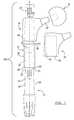
- FIG. 1is a side view of a modular femoral stem implant according to various embodiments
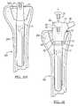
- FIG. 2Ais a side view of a guard according to various embodiments
- FIG. 2Bis a cross-section of a guard along line 2 B- 2 B of FIG. 2A according to various embodiments;
- FIG. 3Ais a side view of a guard according to various embodiments.
- FIG. 3Bis cross-section view of a guard along line 3 B- 3 B of FIG. 3A according to various embodiments;
- FIG. 4is a side view of a guard having a grasping feature according to various embodiments
- FIG. 5is side view of a guard having a grasping feature according to various embodiments.
- FIGS. 6A-6Idepict a surgical method according to various embodiments.
- a modular implant system 100includes a distal stem 10 component, a guard 12 , a proximal body 14 , a femoral head 16 , a trial 18 , and a threaded bolt 20 .
- the guard 12protects at least one of the connection point 21 and proximal end 22 of the distal stem 10 component. The protection prevents any inadvertent scratching or damage to the distal stem 10 or the proximal body 14 while allowing test fitting using the trial 18 to simulate the size and fit of the proximal body 14 relative to the proximal end 22 of the distal stem 10 .
- the modular implant system 100can be provided as a kit which includes multiple combinations of each of the distal stem 10 component, guard 12 , proximal body 14 , femoral head 16 , trial 18 , and bolt 20 .
- the combinationscan include various sizes, lengths, and shapes of any of the modular implant system 100 components to facilitate ease of use and a customized fit.
- the distal stem 10is disposed into a long bone 200 , as best illustrated in FIGS. 6A-6I .
- the distal stem 10is shaped to accommodate insertion into the long bone 200 or repair site.
- the proximal end 22 of the distal stem 10includes a tapered outer surface 24 which mates with the guard 12 .
- the proximal end 22 outer surface 24is shaped as a Morse taper 26 to facilitate the locking fit or tapered fit connection with the proximal body 14 and corresponding tapered sidewall 54 .
- the proximal end 22 of the distal stem 10further defines a threaded distal stem bore 30 which extends partially through the distal stem 10 along a longitudinal axis L. As detailed later herein, the distal stem bore 30 facilitates securing of the modular implant system 100 .
- the length of the Morse tapered region 26 of the distal stem 10 along the longitudinal axisis about 0.5 inches to about 3 inches. It is understood that the length of the Morse tapered region 26 can vary as the size of the distal stem 10 and the modular implant 100 vary to accommodate the particular needs of the patient.
- the guard 12can be made out of a biocompatible polymer, such as polyethylene or PEEK. In various embodiments, the guard 12 can be rigid or semi-rigid. The guard 12 is maintained on the proximal end 22 of the distal stem 10 through surface tension caused by the tight fit therebetween.
- the guard 12includes an outer cylindrical sidewall 32 and an inner sidewall 34 .
- the inner sidewall 34can be tapered as shown in FIGS. 2A and 2B , or the inner sidewall 34 can be cylindrical as shown in FIGS. 3A and 3B . Referring to FIGS. 2A and 2B , in embodiments where the inner sidewall 34 is tapered, the thickness of the guard 12 varies along the length of the guard 12 such that the thickness decreases from the proximal end 36 to the distal end 38 .
- the inner sidewall 34mates with the outer tapered sidewall 24 of the proximal end 22 of the distal stem 10 .
- the inner sidewall 34 of the guard 12is disposed over the proximal end 22 of the distal stem 10 to provide a cap or cover over the proximal end 22 of the distal stem 10 .
- the guard exterior 32is substantially cylindrical.
- the cylindrical shapefacilitates the test fitting of the trial 18 without causing the trial 18 to lock onto the guard 12 or, in other words, provides a readily removable and temporary engagement.
- the cylindrical exterior 32 of the guard 12also facilitates use with other existing modular components.
- the guard 12has an exterior diameter of about 0.25 inches to about 1 inch. Variations in the exterior diameter measurements of the guard 12 are within the scope of the present teachings to accommodate the particular needs of the patient and the various sizes of trials 18 .
- the exterior 32 of the guard 12can also include at least one grasping feature 42 by which the guard 12 can be grasped and manipulated.
- an embodiment of the grasping feature 42includes at least two recessed dimples 44 . The dimples 44 can be used to grasp the guard 12 to remove it from the distal stem 10 .
- an embodiment of the grasping feature 42includes a series of ridges 46 spaced about the exterior surface of the guard 12 . While the ridges 46 of the depicted embodiment are vertical ridges, it is understood that the ridges 46 can also be horizontally disposed about a body of the exterior surface 32 of the guard 12 .
- the guard cavity 40 and the interior sidewall 34have different cross-sections than the guard exterior 32 .
- the guard cavity 40 and interior sidewall 34define a Morse taper 48 cross-section along an inner diameter of the guard 12 .
- the guard cavity 40is mated to the Morse taper 26 at the proximal end 22 of the distal stem 10 .
- the mated shape of the Morse tapers 26 and 48provides a tight connection between the stem 10 and the guard 12 , which protects the proximal end 22 of the distal stem 10 from debris.
- FIGS. 3A and 3Balso protect the proximal end 22 of the distal stem 10 from debris.
- the guard cavity 40 and the length of the guard 12are substantially the same as those of the Morse tapered region 26 of the distal stem 10 . Any difference in length may be an amount which is sufficient to provide adequate protection to the Morse tapered region 26 of the distal stem 10 . As a non-limiting example, the variation between the length of the Morse taper region 26 and the guard cavity 40 can be less than about 15% or less than about 10%.
- the guard 12further defines a bore 50 at the proximal or top end 36 of the guard 12 , which in the depicted embodiment, is opposite to the guard cavity 40 .
- the bore 50 of the guard 12 and the bore 30 in the stem 10are substantially aligned and concentric along longitudinal axis L.
- the proximal body 14includes a cavity 52 which mates with the distal stem 10 .
- the proximal body cavity area 52is defined by a tapered sidewall 54 which provides a removable and adjustable fit with the Morse taper region 26 of the distal stem 10 .
- the proximal body 14further includes a bore 56 which concentrically aligns with the bore 30 of the distal stem 10 .
- the proximal body 14can mate with another component, such as the articulating head 16 of a hip implant via connection point 58 .
- the trial 18includes a cavity 64 which mates with the distal stem 10 .
- the cavity 64is defined by a cylindrical sidewall 66 which provides a removable and adjustable fit with the guard 12 when the guard 12 is placed on the Morse taper region 26 of the distal stem 10 .
- the trial 18 in the system 100has substantially similar outer dimensions to those of the corresponding proximal body 14 .
- One difference between the trial 18 and the proximal body 14is that the trial 18 utilizes the cylindrical interior sidewall 66 to prevent locking with the cylindrical exterior 32 of the guard 12 .
- the trial 18can be used to approximate which proximal body 14 will be used in the system 100 as implanted into the patient.
- the distal stem 10is inserted into a long bone 200 through a bone cavity 202 formed therein, such as the bone cavity 202 prepared in the intramedullary canal 204 .
- the distal stem 10is placed into the bone cavity 202 by impaction using a surgical hammer (not shown), as a non-limiting example.
- the area around the distal stem 10is manipulated through reaming, contouring, or other techniques to provide clearance for the proximal body 14 , as necessary.
- One or several trial bodies 18are then placed on the guard 12 in a manner similar to that described previously in order to determine an appropriate size for the proximal body 14 .
- first trial body 18should a first trial body 18 not fit within the expanded bone cavity 202 or not provide a proper fit, the operator will continue to select other trial bodies 18 until an appropriate fit is achieved.
- the guard 12is removed from the distal stem 10 .
- the cavity 52 of the proximal body 14is then placed on top of the distal stem 10 at the proximal end 22 so that the proximal body 14 and the distal stem 10 are in locking engagement to secure the implant 100 .
- a screw inserter 300can be passed through the aligned opening defined by the distal stem 10 opening 30 and the bore 50 of the guard 12 . It is noted that the screw inserter 300 can be aligned with the distal stem 10 via the guard bore 50 and the stem opening 30 . Sufficient force is then applied to the screw inserter 300 to impact the distal stem 10 into the surrounding intramedullary canal 204 in any suitable manner. For example, a surgical hammer may be used to impact the screw inserter.
- the bone surrounding the proximal end 22 of the distal stem 10can be reamed to accommodate the proximal body 14 .
- the reamingis conducted around the guard 12 , which remains in a fixed position during reaming, to protect the Morse taper 26 connection point of the distal stem 10 .
- a reaming device 302is disposed over the guard 12 , and the reaming device 302 spins about the guard 12 as indicated by the arrows 306 . Leaving the guard 12 in a fixed position during reaming protects the connection point 21 .
- the guard 12serves as a bearing surface for the reaming device 302 .
- the reamingis performed in the bone 200 to a depth that is equal to the length of the guard 12 .
- a usercan measure the height of the guard 12 and/or the size of the proximal body 14 and select a reamer 302 capable of forming an opening having an appropriate depth. This can be achieved by measuring the height of the guard 12 and selecting a reamer 302 having a bit 304 of substantially the same height as the guard 12 .
- maintaining the depth of reaming to substantially the same depth as the guard 12protects the distal stem 10 .
- the bit 304has a conical shape to enlarge the bone cavity 202 in the surrounding bone 200 .
- a bit 304 having a non-conical shapecan also be used to enlarge the cavity 202 .
- the reaming device 302can form a cylindrical bore, a partial cylindrical bore, or any other suitably shaped bore that mates with the cylindrical exterior surface 32 of the guard 12 .
- the selected bit 304will determine the shape of the opening about the guard 12 .
- the conical bit 304will provide a conical shaped opening, while a cylindrical bit will provide a cylindrical shaped opening.
- additional contouring, over that provided by the bit 304 , of the bone 200may be necessary to accommodate the proximal body 14 .
- the additional contouringcan be performed in any suitable manner, such as using a scalpel or a surgical drill, for example.
- FIG. 6Eshows a prepared bone cavity 202 in which the trial 18 can be tested for fit relative to the guard 12 on the distal stem 10 .
- FIG. 6Fthe cylindrical sidewall 66 of the trial cavity 64 is removably engaged with the cylindrical exterior 32 of the guard 12 .
- the mating cylindrical shapes 32 and 66prevent the two bodies from being locked together and provides an adjustable and removable temporary connection therebetween as indicated by arrow 308 .
- Testing the trial 18 relative to the guard 12 on the distal stem 10protects the Morse taper connection 26 of the distal stem 10 . It is understood that a similar test-fitting can be conducted with the femoral head component 16 and connection point 58 of FIG. 1 , as a non-limiting example.
- the guard 12can be removed from the distal stem 10 to expose the outer tapered sidewall 24 of the distal stem 10 .
- the guard 12can be grasped using the grasping feature 42 illustrated as recessed dimple 44 on the guard 12 with forceps 306 , for example. It is understood that the guard 12 can also be removed using a pull-string or other implements.
- the proximal body 14which corresponds to the selected trial 18 , is then disposed over the exposed distal stem 10 and connection point 21 after the guard 12 is removed.
- the connection between the proximal body 14 and the exposed distal stem 10provides a locked fit via the Morse taper interaction therebetween.
- the system 100can be secured using bone cement or other securing devices known in the art, and in embodiments, the proximal body 14 and distal stem 10 can be secured using some combination of bolt 20 , bone cement, or other securing devices.
Landscapes
- Health & Medical Sciences (AREA)
- Orthopedic Medicine & Surgery (AREA)
- Transplantation (AREA)
- Life Sciences & Earth Sciences (AREA)
- Oral & Maxillofacial Surgery (AREA)
- General Health & Medical Sciences (AREA)
- Engineering & Computer Science (AREA)
- Biomedical Technology (AREA)
- Heart & Thoracic Surgery (AREA)
- Veterinary Medicine (AREA)
- Public Health (AREA)
- Animal Behavior & Ethology (AREA)
- Vascular Medicine (AREA)
- Cardiology (AREA)
- Physical Education & Sports Medicine (AREA)
- Surgery (AREA)
- Dentistry (AREA)
- Nuclear Medicine, Radiotherapy & Molecular Imaging (AREA)
- Medical Informatics (AREA)
- Molecular Biology (AREA)
- Prostheses (AREA)
- Surgical Instruments (AREA)
Abstract
Description
Claims (13)
Priority Applications (3)
| Application Number | Priority Date | Filing Date | Title |
|---|---|---|---|
| US12/409,015US8758446B2 (en) | 2009-03-23 | 2009-03-23 | Method and apparatus for protecting modular implant connection |
| US14/293,615US9993343B2 (en) | 2009-03-23 | 2014-06-02 | Method and apparatus for protecting modular implant connection |
| US15/980,217US20180256343A1 (en) | 2009-03-23 | 2018-05-15 | Method and apparatus for protecting modular implant connection |
Applications Claiming Priority (1)
| Application Number | Priority Date | Filing Date | Title |
|---|---|---|---|
| US12/409,015US8758446B2 (en) | 2009-03-23 | 2009-03-23 | Method and apparatus for protecting modular implant connection |
Related Child Applications (1)
| Application Number | Title | Priority Date | Filing Date |
|---|---|---|---|
| US14/293,615DivisionUS9993343B2 (en) | 2009-03-23 | 2014-06-02 | Method and apparatus for protecting modular implant connection |
Publications (2)
| Publication Number | Publication Date |
|---|---|
| US20100241239A1 US20100241239A1 (en) | 2010-09-23 |
| US8758446B2true US8758446B2 (en) | 2014-06-24 |
Family
ID=42738332
Family Applications (3)
| Application Number | Title | Priority Date | Filing Date |
|---|---|---|---|
| US12/409,015Active2031-08-09US8758446B2 (en) | 2009-03-23 | 2009-03-23 | Method and apparatus for protecting modular implant connection |
| US14/293,615Active2029-08-28US9993343B2 (en) | 2009-03-23 | 2014-06-02 | Method and apparatus for protecting modular implant connection |
| US15/980,217AbandonedUS20180256343A1 (en) | 2009-03-23 | 2018-05-15 | Method and apparatus for protecting modular implant connection |
Family Applications After (2)
| Application Number | Title | Priority Date | Filing Date |
|---|---|---|---|
| US14/293,615Active2029-08-28US9993343B2 (en) | 2009-03-23 | 2014-06-02 | Method and apparatus for protecting modular implant connection |
| US15/980,217AbandonedUS20180256343A1 (en) | 2009-03-23 | 2018-05-15 | Method and apparatus for protecting modular implant connection |
Country Status (1)
| Country | Link |
|---|---|
| US (3) | US8758446B2 (en) |
Cited By (6)
| Publication number | Priority date | Publication date | Assignee | Title |
|---|---|---|---|---|
| US9993343B2 (en) | 2009-03-23 | 2018-06-12 | Biomet Manufacturing, Llc | Method and apparatus for protecting modular implant connection |
| US11173050B2 (en)* | 2019-02-22 | 2021-11-16 | Howmedica Osteonics Corp. | Modular femoral trialing system with temporary locking |
| US11202713B2 (en) | 2019-02-22 | 2021-12-21 | Howmedica Osteonics Corp. | Modular femoral trialing system having adjustable height |
| US11311392B2 (en) | 2019-02-22 | 2022-04-26 | Howmedica Osteonics Corp. | Modular femoral trialing system permitting relative movement |
| US20230157706A1 (en)* | 2020-04-23 | 2023-05-25 | Depuy Ireland Unlimited Company | Surgical reamer and method of reaming a bone |
| US12208021B2 (en) | 2018-10-04 | 2025-01-28 | Depuy Ireland Unlimited Company | Prosthesis extraction system |
Families Citing this family (26)
| Publication number | Priority date | Publication date | Assignee | Title |
|---|---|---|---|---|
| US8974540B2 (en) | 2006-12-07 | 2015-03-10 | Ihip Surgical, Llc | Method and apparatus for attachment in a modular hip replacement or fracture fixation device |
| EP2094197B8 (en) | 2006-12-07 | 2016-03-09 | IHip Surgical, LLC | Apparatus for total hip replacement |
| US8579985B2 (en) | 2006-12-07 | 2013-11-12 | Ihip Surgical, Llc | Method and apparatus for hip replacement |
| DE102008045291B4 (en)* | 2008-09-02 | 2013-05-02 | Merete Medical Gmbh | Knee arthrodesis implant |
| DE102008049123B4 (en)* | 2008-09-26 | 2013-06-06 | Merete Medical Gmbh | Modular joint prosthesis |
| US8444699B2 (en)* | 2010-02-18 | 2013-05-21 | Biomet Manufacturing Corp. | Method and apparatus for augmenting bone defects |
| EP2468216B1 (en)* | 2010-12-23 | 2014-05-14 | Baumgart, Rainer, Dipl.-Ing. Dr. med. | Implantable prosthesis for replacing human hip or knee joints and the adjoining bone sections |
| US9289304B1 (en)* | 2013-03-28 | 2016-03-22 | Robert A. Kaufmann | Prosthesis for partial and total joint replacement |
| CN105764448A (en)* | 2013-09-09 | 2016-07-13 | 爱娃·卡布丽缇 | Adjustable Modular Spacer Device for Human Joints |
| PL3054896T3 (en)* | 2013-10-13 | 2018-02-28 | 41Hemiverse Ag | Joint implant |
| US10034754B2 (en)* | 2014-09-12 | 2018-07-31 | Greatbatch Medical S.A. | Taper protection system for orthopedic implants during polishing phases by tribofinishing |
| US9597203B2 (en)* | 2015-03-25 | 2017-03-21 | Tornier, Inc. | Modular humeral implant |
| US9615927B2 (en)* | 2015-03-31 | 2017-04-11 | Depuy Ireland Unlimited Company | Orthopaedic surgical instrument system and method for protecting a femoral stem taper |
| US9724201B2 (en) | 2015-06-30 | 2017-08-08 | Depuy Ireland Unlimited Company | Modular taper seal for orthopaedic prosthetic hip assembly |
| EP3355833B1 (en)* | 2015-09-30 | 2023-01-11 | David Phillip Kirwan | Hip prosthesis |
| GB201705917D0 (en) | 2017-04-12 | 2017-05-24 | Davidson Craig | Femoral trialling kit and assembly |
| US11369492B2 (en) | 2017-08-22 | 2022-06-28 | Depuy Ireland Unlimited Company | Trial neck |
| GB201716107D0 (en) | 2017-10-03 | 2017-11-15 | Depuy Ireland Ultd Co | Trial neck apparatus and method |
| US10828147B1 (en) | 2018-01-21 | 2020-11-10 | Robert A. Kaufmann | Ligament retention device |
| US11376128B2 (en) | 2018-12-31 | 2022-07-05 | Depuy Ireland Unlimited Company | Acetabular orthopaedic prosthesis and method |
| US11103367B2 (en) | 2019-02-15 | 2021-08-31 | Encore Medical, L.P. | Acetabular liner |
| US12171666B2 (en) | 2019-12-10 | 2024-12-24 | Depuy Ireland Unlimited Company | Metal reinforced acetabular shell liner |
| US11628066B2 (en) | 2019-12-11 | 2023-04-18 | Depuy Ireland Unlimited Company | Ceramic acetabular shell liner with a metal ring having a lead-in surface |
| US11291549B2 (en) | 2019-12-11 | 2022-04-05 | Depuy Ireland Unlimited Company | Ceramic acetabular shell liners with augments |
| ES2958860T3 (en)* | 2019-12-16 | 2024-02-15 | Link Waldemar Gmbh Co | Humeral implant component |
| US12127955B2 (en) | 2021-04-29 | 2024-10-29 | Depuy Ireland Unlimited Company | Trial component and method |
Citations (15)
| Publication number | Priority date | Publication date | Assignee | Title |
|---|---|---|---|---|
| US3818514A (en) | 1971-08-09 | 1974-06-25 | Thackray C F Ltd | Femoral prosthesis with removable protective sheath |
| US3918441A (en) | 1974-09-17 | 1975-11-11 | Philip E Getscher | Intramedullary hip pin |
| US4227265A (en) | 1977-05-23 | 1980-10-14 | Sulzer Brothers Limited | Bone implant with plastic insert between elements of different mechanical properties |
| US4488319A (en) | 1981-10-26 | 1984-12-18 | Clemson University | Method of two-stage implantation of a joint prosthesis and prosthetic product |
| US4963155A (en)* | 1989-08-30 | 1990-10-16 | Zimmer, Inc. | Attachment mechanism for modular surgical products |
| US6238436B1 (en) | 1994-11-19 | 2001-05-29 | Biomet, Merck Deutschland Gmbh | Modular artificial hip joint |
| US6264699B1 (en) | 1998-11-23 | 2001-07-24 | Depuy Orthopaedics, Inc. | Modular stem and sleeve prosthesis |
| US20020099447A1 (en)* | 2000-04-26 | 2002-07-25 | Dana Mears | Method and apparatus for performing a minimally invasive total hip arthroplasty |
| US20020193882A1 (en) | 2001-05-18 | 2002-12-19 | Hansjorg Koller | Trial balls for hip joint prostheses |
| US20040254646A1 (en)* | 2003-06-16 | 2004-12-16 | Stone Kevin T. | Provisional coupling mechanism |
| US6863692B2 (en) | 2002-11-14 | 2005-03-08 | Zimmer Technology, Inc. | Implant sleeve and method |
| US20060015112A1 (en)* | 2003-01-29 | 2006-01-19 | Mcgovern Michael A | Apparatus and method for preparing bone for anti-rotational implantation of an orthopedic endoprosthesis |
| US20070100464A1 (en) | 2005-10-27 | 2007-05-03 | Zimmer Technology, Inc. | Orthopaedic implant sleeve and method |
| US20070244486A1 (en) | 2003-12-24 | 2007-10-18 | Alex Hogg | Reamer Guide and Method |
| US20090270867A1 (en)* | 2008-04-28 | 2009-10-29 | Didier Poncet | Reamer guide for revision procedure |
Family Cites Families (7)
| Publication number | Priority date | Publication date | Assignee | Title |
|---|---|---|---|---|
| DE3340767A1 (en)* | 1983-11-08 | 1985-05-15 | Mecron Medizinische Produkte Gmbh, 1000 Berlin | KIT FOR A RESECTION PROSTHESIS |
| US4608052A (en)* | 1984-04-25 | 1986-08-26 | Minnesota Mining And Manufacturing Company | Implant with attachment surface |
| US5336226A (en)* | 1992-08-11 | 1994-08-09 | Chapman Lake Instruments, Inc. | Bone face cutter |
| WO1997018776A1 (en)* | 1995-11-20 | 1997-05-29 | Artos Medizinische Produkte Gmbh | Modular endoprosthesis |
| US6616697B2 (en)* | 2001-03-13 | 2003-09-09 | Nicholas G. Sotereanos | Hip implant assembly |
| US20080021567A1 (en)* | 2006-07-18 | 2008-01-24 | Zimmer Technology, Inc. | Modular orthopaedic component case |
| US8758446B2 (en) | 2009-03-23 | 2014-06-24 | Biomet Manufacturing, Llc | Method and apparatus for protecting modular implant connection |
- 2009
- 2009-03-23USUS12/409,015patent/US8758446B2/enactiveActive
- 2014
- 2014-06-02USUS14/293,615patent/US9993343B2/enactiveActive
- 2018
- 2018-05-15USUS15/980,217patent/US20180256343A1/ennot_activeAbandoned
Patent Citations (15)
| Publication number | Priority date | Publication date | Assignee | Title |
|---|---|---|---|---|
| US3818514A (en) | 1971-08-09 | 1974-06-25 | Thackray C F Ltd | Femoral prosthesis with removable protective sheath |
| US3918441A (en) | 1974-09-17 | 1975-11-11 | Philip E Getscher | Intramedullary hip pin |
| US4227265A (en) | 1977-05-23 | 1980-10-14 | Sulzer Brothers Limited | Bone implant with plastic insert between elements of different mechanical properties |
| US4488319A (en) | 1981-10-26 | 1984-12-18 | Clemson University | Method of two-stage implantation of a joint prosthesis and prosthetic product |
| US4963155A (en)* | 1989-08-30 | 1990-10-16 | Zimmer, Inc. | Attachment mechanism for modular surgical products |
| US6238436B1 (en) | 1994-11-19 | 2001-05-29 | Biomet, Merck Deutschland Gmbh | Modular artificial hip joint |
| US6264699B1 (en) | 1998-11-23 | 2001-07-24 | Depuy Orthopaedics, Inc. | Modular stem and sleeve prosthesis |
| US20020099447A1 (en)* | 2000-04-26 | 2002-07-25 | Dana Mears | Method and apparatus for performing a minimally invasive total hip arthroplasty |
| US20020193882A1 (en) | 2001-05-18 | 2002-12-19 | Hansjorg Koller | Trial balls for hip joint prostheses |
| US6863692B2 (en) | 2002-11-14 | 2005-03-08 | Zimmer Technology, Inc. | Implant sleeve and method |
| US20060015112A1 (en)* | 2003-01-29 | 2006-01-19 | Mcgovern Michael A | Apparatus and method for preparing bone for anti-rotational implantation of an orthopedic endoprosthesis |
| US20040254646A1 (en)* | 2003-06-16 | 2004-12-16 | Stone Kevin T. | Provisional coupling mechanism |
| US20070244486A1 (en) | 2003-12-24 | 2007-10-18 | Alex Hogg | Reamer Guide and Method |
| US20070100464A1 (en) | 2005-10-27 | 2007-05-03 | Zimmer Technology, Inc. | Orthopaedic implant sleeve and method |
| US20090270867A1 (en)* | 2008-04-28 | 2009-10-29 | Didier Poncet | Reamer guide for revision procedure |
Non-Patent Citations (2)
| Title |
|---|
| "Restoration® Modular Revision Hip System Surgical Protocol, Restoration® Modular Cone Body/Conical Distal Stem Femoral Components Using the Restoration® Modular Instrument System," brochure, (2005) Stryker, pp. 1-21. |
| "Restoration® Modular Revision Hip System, Product Reference Guide for Cone/Conical and Broached/Fluted & Plasma Implants and Instruments," brochure, (2004) Stryker, pp. 1-12. |
Cited By (6)
| Publication number | Priority date | Publication date | Assignee | Title |
|---|---|---|---|---|
| US9993343B2 (en) | 2009-03-23 | 2018-06-12 | Biomet Manufacturing, Llc | Method and apparatus for protecting modular implant connection |
| US12208021B2 (en) | 2018-10-04 | 2025-01-28 | Depuy Ireland Unlimited Company | Prosthesis extraction system |
| US11173050B2 (en)* | 2019-02-22 | 2021-11-16 | Howmedica Osteonics Corp. | Modular femoral trialing system with temporary locking |
| US11202713B2 (en) | 2019-02-22 | 2021-12-21 | Howmedica Osteonics Corp. | Modular femoral trialing system having adjustable height |
| US11311392B2 (en) | 2019-02-22 | 2022-04-26 | Howmedica Osteonics Corp. | Modular femoral trialing system permitting relative movement |
| US20230157706A1 (en)* | 2020-04-23 | 2023-05-25 | Depuy Ireland Unlimited Company | Surgical reamer and method of reaming a bone |
Also Published As
| Publication number | Publication date |
|---|---|
| US20100241239A1 (en) | 2010-09-23 |
| US20140277556A1 (en) | 2014-09-18 |
| US20180256343A1 (en) | 2018-09-13 |
| US9993343B2 (en) | 2018-06-12 |
Similar Documents
| Publication | Publication Date | Title |
|---|---|---|
| US8758446B2 (en) | Method and apparatus for protecting modular implant connection | |
| US10758363B2 (en) | Transforaminal intersomatic cage for an intervertebral fusion graft and an instrument for implanting the cage | |
| US9763798B2 (en) | System and method for implanting a secondary glenoid prosthesis | |
| US9561109B2 (en) | Orthopaedic implant and method of installing same | |
| US11759335B2 (en) | Engineered sterile cartilage allograft implant plug with sterile, specific instrument kit(s) | |
| JP6591142B2 (en) | Tibial trial instrument for offset setting | |
| US10201428B2 (en) | Orthopaedic surgical instrument system and method for protecting a femoral stem taper | |
| US20140012264A1 (en) | Total hip arthroplasty | |
| US10166106B2 (en) | Methods and devices for a surgical hip replacement procedure | |
| US20090240256A1 (en) | Method And Apparatus For Implanting an Augment | |
| CN105431111B (en) | Implant is tested | |
| JP7608462B2 (en) | REMOVABLE ANGLED GUIDE FOR IMPLANT INSERTION TOOL AND ASSOCIATED SURGICAL METHODS - Patent application | |
| US20090182334A1 (en) | Method and Apparatus for Impacting Bone Material | |
| US7255716B2 (en) | Method and instruments for inserting modular implant components |
Legal Events
| Date | Code | Title | Description |
|---|---|---|---|
| AS | Assignment | Owner name:BIOMET MANUFACTURING CORP., INDIANA Free format text:ASSIGNMENT OF ASSIGNORS INTEREST;ASSIGNOR:SMITH, AARON P.;REEL/FRAME:022435/0299 Effective date:20090320 | |
| AS | Assignment | Owner name:BANK OF AMERICA, N.A., AS ADMINISTRATIVE AGENT FOR Free format text:SECURITY AGREEMENT;ASSIGNORS:LVB ACQUISITION, INC.;BIOMET, INC.;BIOMET 3I, LLC;AND OTHERS;REEL/FRAME:023505/0241 Effective date:20091111 | |
| AS | Assignment | Owner name:BIOMET MANUFACTURING, LLC, INDIANA Free format text:ASSIGNMENT OF ASSIGNORS INTEREST;ASSIGNOR:BIOMET MANUFACTURING CORPORATION;REEL/FRAME:032128/0493 Effective date:20130603 | |
| STCF | Information on status: patent grant | Free format text:PATENTED CASE | |
| AS | Assignment | Owner name:BIOMET, INC., INDIANA Free format text:RELEASE OF SECURITY INTEREST IN PATENTS RECORDED AT REEL 023505/ FRAME 0241;ASSIGNOR:BANK OF AMERICA, N.A., AS ADMINISTRATIVE AGENT;REEL/FRAME:037155/0082 Effective date:20150624 Owner name:BIOMET FAIR LAWN LLC, NEW JERSEY Free format text:RELEASE OF SECURITY INTEREST IN PATENTS RECORDED AT REEL 023505/ FRAME 0241;ASSIGNOR:BANK OF AMERICA, N.A., AS ADMINISTRATIVE AGENT;REEL/FRAME:037155/0082 Effective date:20150624 Owner name:ELECTR-OBIOLOGY, LLC, INDIANA Free format text:RELEASE OF SECURITY INTEREST IN PATENTS RECORDED AT REEL 023505/ FRAME 0241;ASSIGNOR:BANK OF AMERICA, N.A., AS ADMINISTRATIVE AGENT;REEL/FRAME:037155/0082 Effective date:20150624 Owner name:CROSS MEDICAL PRODUCTS, LLC, CALIFORNIA Free format text:RELEASE OF SECURITY INTEREST IN PATENTS RECORDED AT REEL 023505/ FRAME 0241;ASSIGNOR:BANK OF AMERICA, N.A., AS ADMINISTRATIVE AGENT;REEL/FRAME:037155/0082 Effective date:20150624 Owner name:IMPLANT INNOVATIONS HOLDINGS, LLC, INDIANA Free format text:RELEASE OF SECURITY INTEREST IN PATENTS RECORDED AT REEL 023505/ FRAME 0241;ASSIGNOR:BANK OF AMERICA, N.A., AS ADMINISTRATIVE AGENT;REEL/FRAME:037155/0082 Effective date:20150624 Owner name:BIOMET MICROFIXATION, LLC, FLORIDA Free format text:RELEASE OF SECURITY INTEREST IN PATENTS RECORDED AT REEL 023505/ FRAME 0241;ASSIGNOR:BANK OF AMERICA, N.A., AS ADMINISTRATIVE AGENT;REEL/FRAME:037155/0082 Effective date:20150624 Owner name:BIOMET FLORIDA SERVICES, LLC, INDIANA Free format text:RELEASE OF SECURITY INTEREST IN PATENTS RECORDED AT REEL 023505/ FRAME 0241;ASSIGNOR:BANK OF AMERICA, N.A., AS ADMINISTRATIVE AGENT;REEL/FRAME:037155/0082 Effective date:20150624 Owner name:INTERPORE CROSS INTERNATIONAL, LLC, CALIFORNIA Free format text:RELEASE OF SECURITY INTEREST IN PATENTS RECORDED AT REEL 023505/ FRAME 0241;ASSIGNOR:BANK OF AMERICA, N.A., AS ADMINISTRATIVE AGENT;REEL/FRAME:037155/0082 Effective date:20150624 Owner name:BIOMET SPORTS MEDICINE, LLC, INDIANA Free format text:RELEASE OF SECURITY INTEREST IN PATENTS RECORDED AT REEL 023505/ FRAME 0241;ASSIGNOR:BANK OF AMERICA, N.A., AS ADMINISTRATIVE AGENT;REEL/FRAME:037155/0082 Effective date:20150624 Owner name:LVB ACQUISITION, INC., INDIANA Free format text:RELEASE OF SECURITY INTEREST IN PATENTS RECORDED AT REEL 023505/ FRAME 0241;ASSIGNOR:BANK OF AMERICA, N.A., AS ADMINISTRATIVE AGENT;REEL/FRAME:037155/0082 Effective date:20150624 Owner name:EBI MEDICAL SYSTEMS, LLC, INDIANA Free format text:RELEASE OF SECURITY INTEREST IN PATENTS RECORDED AT REEL 023505/ FRAME 0241;ASSIGNOR:BANK OF AMERICA, N.A., AS ADMINISTRATIVE AGENT;REEL/FRAME:037155/0082 Effective date:20150624 Owner name:KIRSCHNER MEDICAL CORPORATION, INDIANA Free format text:RELEASE OF SECURITY INTEREST IN PATENTS RECORDED AT REEL 023505/ FRAME 0241;ASSIGNOR:BANK OF AMERICA, N.A., AS ADMINISTRATIVE AGENT;REEL/FRAME:037155/0082 Effective date:20150624 Owner name:BIOMET ORTHOPEDICS, LLC, INDIANA Free format text:RELEASE OF SECURITY INTEREST IN PATENTS RECORDED AT REEL 023505/ FRAME 0241;ASSIGNOR:BANK OF AMERICA, N.A., AS ADMINISTRATIVE AGENT;REEL/FRAME:037155/0082 Effective date:20150624 Owner name:BIOMET INTERNATIONAL LTD., INDIANA Free format text:RELEASE OF SECURITY INTEREST IN PATENTS RECORDED AT REEL 023505/ FRAME 0241;ASSIGNOR:BANK OF AMERICA, N.A., AS ADMINISTRATIVE AGENT;REEL/FRAME:037155/0082 Effective date:20150624 Owner name:BIOMET MANUFACTURING CORPORATION, INDIANA Free format text:RELEASE OF SECURITY INTEREST IN PATENTS RECORDED AT REEL 023505/ FRAME 0241;ASSIGNOR:BANK OF AMERICA, N.A., AS ADMINISTRATIVE AGENT;REEL/FRAME:037155/0082 Effective date:20150624 Owner name:INTERPORE SPINE, LTD., CALIFORNIA Free format text:RELEASE OF SECURITY INTEREST IN PATENTS RECORDED AT REEL 023505/ FRAME 0241;ASSIGNOR:BANK OF AMERICA, N.A., AS ADMINISTRATIVE AGENT;REEL/FRAME:037155/0082 Effective date:20150624 Owner name:EBI HOLDINGS, LLC, INDIANA Free format text:RELEASE OF SECURITY INTEREST IN PATENTS RECORDED AT REEL 023505/ FRAME 0241;ASSIGNOR:BANK OF AMERICA, N.A., AS ADMINISTRATIVE AGENT;REEL/FRAME:037155/0082 Effective date:20150624 Owner name:BIOMET BIOLOGICS, LLC., INDIANA Free format text:RELEASE OF SECURITY INTEREST IN PATENTS RECORDED AT REEL 023505/ FRAME 0241;ASSIGNOR:BANK OF AMERICA, N.A., AS ADMINISTRATIVE AGENT;REEL/FRAME:037155/0082 Effective date:20150624 Owner name:BIOMET TRAVEL, INC., INDIANA Free format text:RELEASE OF SECURITY INTEREST IN PATENTS RECORDED AT REEL 023505/ FRAME 0241;ASSIGNOR:BANK OF AMERICA, N.A., AS ADMINISTRATIVE AGENT;REEL/FRAME:037155/0082 Effective date:20150624 Owner name:BIOMET LEASING, INC., INDIANA Free format text:RELEASE OF SECURITY INTEREST IN PATENTS RECORDED AT REEL 023505/ FRAME 0241;ASSIGNOR:BANK OF AMERICA, N.A., AS ADMINISTRATIVE AGENT;REEL/FRAME:037155/0082 Effective date:20150624 Owner name:BIOMET HOLDINGS LTD., INDIANA Free format text:RELEASE OF SECURITY INTEREST IN PATENTS RECORDED AT REEL 023505/ FRAME 0241;ASSIGNOR:BANK OF AMERICA, N.A., AS ADMINISTRATIVE AGENT;REEL/FRAME:037155/0082 Effective date:20150624 Owner name:EBI, LLC, INDIANA Free format text:RELEASE OF SECURITY INTEREST IN PATENTS RECORDED AT REEL 023505/ FRAME 0241;ASSIGNOR:BANK OF AMERICA, N.A., AS ADMINISTRATIVE AGENT;REEL/FRAME:037155/0082 Effective date:20150624 Owner name:BIOLECTRON, INC., INDIANA Free format text:RELEASE OF SECURITY INTEREST IN PATENTS RECORDED AT REEL 023505/ FRAME 0241;ASSIGNOR:BANK OF AMERICA, N.A., AS ADMINISTRATIVE AGENT;REEL/FRAME:037155/0082 Effective date:20150624 Owner name:BIOMET 3I, LLC, FLORIDA Free format text:RELEASE OF SECURITY INTEREST IN PATENTS RECORDED AT REEL 023505/ FRAME 0241;ASSIGNOR:BANK OF AMERICA, N.A., AS ADMINISTRATIVE AGENT;REEL/FRAME:037155/0082 Effective date:20150624 Owner name:BIOMET EUROPE LTD., INDIANA Free format text:RELEASE OF SECURITY INTEREST IN PATENTS RECORDED AT REEL 023505/ FRAME 0241;ASSIGNOR:BANK OF AMERICA, N.A., AS ADMINISTRATIVE AGENT;REEL/FRAME:037155/0082 Effective date:20150624 | |
| MAFP | Maintenance fee payment | Free format text:PAYMENT OF MAINTENANCE FEE, 4TH YEAR, LARGE ENTITY (ORIGINAL EVENT CODE: M1551) Year of fee payment:4 | |
| MAFP | Maintenance fee payment | Free format text:PAYMENT OF MAINTENANCE FEE, 8TH YEAR, LARGE ENTITY (ORIGINAL EVENT CODE: M1552); ENTITY STATUS OF PATENT OWNER: LARGE ENTITY Year of fee payment:8 |