US8758367B2 - Anchor delivery system - Google Patents
Anchor delivery systemDownload PDFInfo
- Publication number
- US8758367B2 US8758367B2US11/839,721US83972107AUS8758367B2US 8758367 B2US8758367 B2US 8758367B2US 83972107 AUS83972107 AUS 83972107AUS 8758367 B2US8758367 B2US 8758367B2
- Authority
- US
- United States
- Prior art keywords
- guide
- anchor
- bone
- shaft
- tool
- Prior art date
- Legal status (The legal status is an assumption and is not a legal conclusion. Google has not performed a legal analysis and makes no representation as to the accuracy of the status listed.)
- Active, expires
Links
- 238000000034methodMethods0.000claimsabstractdescription29
- 210000004872soft tissueAnatomy0.000claimsabstractdescription6
- 210000000988bone and boneAnatomy0.000claimsdescription44
- 210000001519tissueAnatomy0.000claimsdescription4
- 230000000717retained effectEffects0.000claimsdescription2
- 238000001356surgical procedureMethods0.000description10
- 230000008439repair processEffects0.000description6
- 238000005553drillingMethods0.000description5
- 238000004873anchoringMethods0.000description4
- 239000000560biocompatible materialSubstances0.000description4
- 239000000463materialSubstances0.000description4
- 229910001220stainless steelInorganic materials0.000description4
- 239000010935stainless steelSubstances0.000description4
- 239000007769metal materialSubstances0.000description3
- 210000003484anatomyAnatomy0.000description2
- 238000005452bendingMethods0.000description2
- 230000006835compressionEffects0.000description2
- 238000007906compressionMethods0.000description2
- 230000017423tissue regenerationEffects0.000description2
- 238000012800visualizationMethods0.000description2
- 238000003466weldingMethods0.000description2
- RTAQQCXQSZGOHL-UHFFFAOYSA-NTitaniumChemical compound[Ti]RTAQQCXQSZGOHL-UHFFFAOYSA-N0.000description1
- 210000003423ankleAnatomy0.000description1
- 230000008878couplingEffects0.000description1
- 238000010168coupling processMethods0.000description1
- 238000005859coupling reactionMethods0.000description1
- 239000003814drugSubstances0.000description1
- 230000000694effectsEffects0.000description1
- 210000001513elbowAnatomy0.000description1
- 210000002683footAnatomy0.000description1
- 238000003780insertionMethods0.000description1
- 230000037431insertionEffects0.000description1
- 210000003127kneeAnatomy0.000description1
- 238000007726management methodMethods0.000description1
- 238000012986modificationMethods0.000description1
- 230000004048modificationEffects0.000description1
- 238000000465mouldingMethods0.000description1
- 229910052755nonmetalInorganic materials0.000description1
- 238000002355open surgical procedureMethods0.000description1
- 230000035515penetrationEffects0.000description1
- 239000002861polymer materialSubstances0.000description1
- 238000010079rubber tappingMethods0.000description1
- 239000010936titaniumSubstances0.000description1
- 229910052719titaniumInorganic materials0.000description1
Images


Classifications
- A—HUMAN NECESSITIES
- A61—MEDICAL OR VETERINARY SCIENCE; HYGIENE
- A61B—DIAGNOSIS; SURGERY; IDENTIFICATION
- A61B17/00—Surgical instruments, devices or methods
- A61B17/16—Instruments for performing osteoclasis; Drills or chisels for bones; Trepans
- A61B17/1613—Component parts
- A61B17/1615—Drill bits, i.e. rotating tools extending from a handpiece to contact the worked material
- A—HUMAN NECESSITIES
- A61—MEDICAL OR VETERINARY SCIENCE; HYGIENE
- A61B—DIAGNOSIS; SURGERY; IDENTIFICATION
- A61B17/00—Surgical instruments, devices or methods
- A61B17/56—Surgical instruments or methods for treatment of bones or joints; Devices specially adapted therefor
- A61B17/58—Surgical instruments or methods for treatment of bones or joints; Devices specially adapted therefor for osteosynthesis, e.g. bone plates, screws or setting implements
- A61B17/88—Osteosynthesis instruments; Methods or means for implanting or extracting internal or external fixation devices
- A61B17/8875—Screwdrivers, spanners or wrenches
- A61B17/8886—Screwdrivers, spanners or wrenches holding the screw head
- A61B17/8888—Screwdrivers, spanners or wrenches holding the screw head at its central region
- A—HUMAN NECESSITIES
- A61—MEDICAL OR VETERINARY SCIENCE; HYGIENE
- A61B—DIAGNOSIS; SURGERY; IDENTIFICATION
- A61B17/00—Surgical instruments, devices or methods
- A61B17/04—Surgical instruments, devices or methods for suturing wounds; Holders or packages for needles or suture materials
- A61B17/0401—Suture anchors, buttons or pledgets, i.e. means for attaching sutures to bone, cartilage or soft tissue; Instruments for applying or removing suture anchors
- A—HUMAN NECESSITIES
- A61—MEDICAL OR VETERINARY SCIENCE; HYGIENE
- A61B—DIAGNOSIS; SURGERY; IDENTIFICATION
- A61B17/00—Surgical instruments, devices or methods
- A61B17/16—Instruments for performing osteoclasis; Drills or chisels for bones; Trepans
- A61B17/17—Guides or aligning means for drills, mills, pins or wires
- A61B17/1714—Guides or aligning means for drills, mills, pins or wires for applying tendons or ligaments
- A—HUMAN NECESSITIES
- A61—MEDICAL OR VETERINARY SCIENCE; HYGIENE
- A61B—DIAGNOSIS; SURGERY; IDENTIFICATION
- A61B17/00—Surgical instruments, devices or methods
- A61B17/04—Surgical instruments, devices or methods for suturing wounds; Holders or packages for needles or suture materials
- A61B17/0401—Suture anchors, buttons or pledgets, i.e. means for attaching sutures to bone, cartilage or soft tissue; Instruments for applying or removing suture anchors
- A61B2017/0409—Instruments for applying suture anchors
- A—HUMAN NECESSITIES
- A61—MEDICAL OR VETERINARY SCIENCE; HYGIENE
- A61B—DIAGNOSIS; SURGERY; IDENTIFICATION
- A61B17/00—Surgical instruments, devices or methods
- A61B17/04—Surgical instruments, devices or methods for suturing wounds; Holders or packages for needles or suture materials
- A61B17/0401—Suture anchors, buttons or pledgets, i.e. means for attaching sutures to bone, cartilage or soft tissue; Instruments for applying or removing suture anchors
- A61B2017/0411—Instruments for removing suture anchors
- A—HUMAN NECESSITIES
- A61—MEDICAL OR VETERINARY SCIENCE; HYGIENE
- A61B—DIAGNOSIS; SURGERY; IDENTIFICATION
- A61B17/00—Surgical instruments, devices or methods
- A61B17/04—Surgical instruments, devices or methods for suturing wounds; Holders or packages for needles or suture materials
- A61B17/0401—Suture anchors, buttons or pledgets, i.e. means for attaching sutures to bone, cartilage or soft tissue; Instruments for applying or removing suture anchors
- A61B2017/0412—Suture anchors, buttons or pledgets, i.e. means for attaching sutures to bone, cartilage or soft tissue; Instruments for applying or removing suture anchors having anchoring barbs or pins extending outwardly from suture anchor body
- A—HUMAN NECESSITIES
- A61—MEDICAL OR VETERINARY SCIENCE; HYGIENE
- A61B—DIAGNOSIS; SURGERY; IDENTIFICATION
- A61B17/00—Surgical instruments, devices or methods
- A61B17/04—Surgical instruments, devices or methods for suturing wounds; Holders or packages for needles or suture materials
- A61B17/0401—Suture anchors, buttons or pledgets, i.e. means for attaching sutures to bone, cartilage or soft tissue; Instruments for applying or removing suture anchors
- A61B2017/0414—Suture anchors, buttons or pledgets, i.e. means for attaching sutures to bone, cartilage or soft tissue; Instruments for applying or removing suture anchors having a suture-receiving opening, e.g. lateral opening
- A—HUMAN NECESSITIES
- A61—MEDICAL OR VETERINARY SCIENCE; HYGIENE
- A61B—DIAGNOSIS; SURGERY; IDENTIFICATION
- A61B17/00—Surgical instruments, devices or methods
- A61B17/04—Surgical instruments, devices or methods for suturing wounds; Holders or packages for needles or suture materials
- A61B17/0401—Suture anchors, buttons or pledgets, i.e. means for attaching sutures to bone, cartilage or soft tissue; Instruments for applying or removing suture anchors
- A61B2017/0427—Suture anchors, buttons or pledgets, i.e. means for attaching sutures to bone, cartilage or soft tissue; Instruments for applying or removing suture anchors having anchoring barbs or pins extending outwardly from the anchor body
- A—HUMAN NECESSITIES
- A61—MEDICAL OR VETERINARY SCIENCE; HYGIENE
- A61B—DIAGNOSIS; SURGERY; IDENTIFICATION
- A61B17/00—Surgical instruments, devices or methods
- A61B17/04—Surgical instruments, devices or methods for suturing wounds; Holders or packages for needles or suture materials
- A61B17/0401—Suture anchors, buttons or pledgets, i.e. means for attaching sutures to bone, cartilage or soft tissue; Instruments for applying or removing suture anchors
- A61B2017/044—Suture anchors, buttons or pledgets, i.e. means for attaching sutures to bone, cartilage or soft tissue; Instruments for applying or removing suture anchors with a threaded shaft, e.g. screws
- A—HUMAN NECESSITIES
- A61—MEDICAL OR VETERINARY SCIENCE; HYGIENE
- A61B—DIAGNOSIS; SURGERY; IDENTIFICATION
- A61B17/00—Surgical instruments, devices or methods
- A61B17/04—Surgical instruments, devices or methods for suturing wounds; Holders or packages for needles or suture materials
- A61B17/0401—Suture anchors, buttons or pledgets, i.e. means for attaching sutures to bone, cartilage or soft tissue; Instruments for applying or removing suture anchors
- A61B2017/0445—Suture anchors, buttons or pledgets, i.e. means for attaching sutures to bone, cartilage or soft tissue; Instruments for applying or removing suture anchors cannulated, e.g. with a longitudinal through-hole for passage of an instrument
- A—HUMAN NECESSITIES
- A61—MEDICAL OR VETERINARY SCIENCE; HYGIENE
- A61B—DIAGNOSIS; SURGERY; IDENTIFICATION
- A61B17/00—Surgical instruments, devices or methods
- A61B17/04—Surgical instruments, devices or methods for suturing wounds; Holders or packages for needles or suture materials
- A61B17/0401—Suture anchors, buttons or pledgets, i.e. means for attaching sutures to bone, cartilage or soft tissue; Instruments for applying or removing suture anchors
- A61B2017/0464—Suture anchors, buttons or pledgets, i.e. means for attaching sutures to bone, cartilage or soft tissue; Instruments for applying or removing suture anchors for soft tissue
- A—HUMAN NECESSITIES
- A61—MEDICAL OR VETERINARY SCIENCE; HYGIENE
- A61B—DIAGNOSIS; SURGERY; IDENTIFICATION
- A61B17/00—Surgical instruments, devices or methods
- A61B17/04—Surgical instruments, devices or methods for suturing wounds; Holders or packages for needles or suture materials
- A61B2017/0496—Surgical instruments, devices or methods for suturing wounds; Holders or packages for needles or suture materials for tensioning sutures
- A—HUMAN NECESSITIES
- A61—MEDICAL OR VETERINARY SCIENCE; HYGIENE
- A61B—DIAGNOSIS; SURGERY; IDENTIFICATION
- A61B90/00—Instruments, implements or accessories specially adapted for surgery or diagnosis and not covered by any of the groups A61B1/00 - A61B50/00, e.g. for luxation treatment or for protecting wound edges
- A61B90/03—Automatic limiting or abutting means, e.g. for safety
- A61B2090/033—Abutting means, stops, e.g. abutting on tissue or skin
- A61B2090/034—Abutting means, stops, e.g. abutting on tissue or skin abutting on parts of the device itself
- A—HUMAN NECESSITIES
- A61—MEDICAL OR VETERINARY SCIENCE; HYGIENE
- A61B—DIAGNOSIS; SURGERY; IDENTIFICATION
- A61B90/00—Instruments, implements or accessories specially adapted for surgery or diagnosis and not covered by any of the groups A61B1/00 - A61B50/00, e.g. for luxation treatment or for protecting wound edges
- A61B90/06—Measuring instruments not otherwise provided for
- A61B2090/062—Measuring instruments not otherwise provided for penetration depth
Definitions
- the present disclosurerelates to methods and devices for use in surgical procedures and, more specifically, to an arthroscopic method and apparatus for installing a suture anchor into bone.
- suture anchorsMedical devices and methods for attaching soft tissue to bone have been developed. Of particular interest, especially in sports medicine procedures, are suture anchors.
- a suture anchoris typically inserted into and fixed in a bore hole drilled into a bone at a surgical repair site.
- Suturesare typically coupled to the anchor and are used to secure the soft tissue to the bone in order to effect the repair.
- accuracy in the placement of suture anchors in boneis required to achieve consistently positive surgical outcomes, requiring substantial skill on the part of the surgeon.
- An aspect of the present disclosurerelates to an anchor delivery system.
- the systemincludes a guide and an anchor delivery tool disposed within the guide.
- the toolincludes a shaft and a handle coupled to the shaft.
- the handleincludes a hub and a nose cone coupled to the hub.
- the toolfurther includes a knob coupled to the hub and located between the handle and the nose cone.
- the systemfurther includes an anchor, such as a suture anchor, coupled to a distal portion of the shaft.
- a shaft of the guideis bent relative to a longitudinal axis of the guide.
- the anchor delivery guideincludes a high strength material.
- the present disclosurerelates to an anchor delivery tool.
- the toolincludes a shaft and a handle coupled to the shaft.
- the handleincludes a hub and a nose cone coupled to the hub.
- the toolfurther includes a knob coupled to the hub and located between the handle and the nose cone.
- the handleincludes at least one suture retaining feature, such as a tab.
- the handleincludes multiple suture retaining features.
- the handleincludes a through passage extending a length of the handle.
- the knobis movable between a first position and a second position with respect to the nose cone.
- the knobis spring-loaded against the nose cone.
- the knobincludes laterally extending wings.
- the nose coneincludes a cavity wherein the cavity houses a distal portion of the knob when the knob is in a first position.
- the shaftincludes an area of reduced diameter, wherein a length of the area is about 3 mm.
- the shaftincludes at least two channels extending a length of the shaft.
- the shaftincludes a tip, the tip extending from a distal portion of the shaft.
- the present disclosurerelates to a method of repairing soft tissue.
- the methodincludes providing a guide; providing an anchor delivery tool, the tool including a shaft and a handle coupled to the shaft, the shaft including a suture anchor coupled to a distal end of the shaft, the handle including a hub and a nose cone coupled to the hub; introducing the guide into a body; advancing the tool through the guide; placing the anchor in bone; and securing the tissue to the bone with the suture.
- the methodfurther includes a knob coupled to the hub and located between the handle and the nose cone.
- the methodincludes introduction of the guide into the body occurring in a percutaneous manner via the use of an obturator, such as a cannulated obturator.
- full advancement of the tool into the guideis obtained when a distal portion of the nose cone abuts a proximal portion of the guide.
- the distal portion of the nose cone and the proximal portion of the guideare flat.
- full advancement of the tool into the guideis obtained when a laser mark at a distal portion of the tool is centered in an opening at a distal portion of the guide.
- a proximal portion of the anchoris located about 3 mm below a surface of the bone when a distal portion of the nose cone abuts a proximal portion of the guide. In yet a further embodiment, a proximal portion of the anchor is located about 3 mm below a surface of the bone when a laser mark at a distal portion of the tool is centered in an opening at a distal portion of the guide. In another embodiment, the tool is located at an angle of about 90 degrees relative to the bone upon placement of the anchor in the bone. In yet another embodiment, the tool is located at an angle of less than about 90 degrees relative to the bone upon placement of the anchor in the bone. In a further embodiment, the tool is located at an angle of more than about 90 degrees relative to the bone upon placement of the anchor in the bone.
- FIG. 1shows an isometric view of the guide of the present disclosure.
- FIG. 1Ashows an enlarged view of a distal portion of the guide of FIG. 1 .
- FIG. 2shows an isometric view of a first alternative embodiment of the guide of FIG. 1 .
- FIG. 3shows an isometric view of a second alternative embodiment of the guide of FIG. 1 .
- FIG. 3Ashows an enlarged view of a distal portion of the guide of FIG. 3 .
- FIG. 4shows a side view of the guide of FIG. 3 .
- FIG. 5shows an isometric view of a third alternative embodiment of the guide of FIG. 1 .
- FIG. 5Ashows an enlarged view of a distal portion of the guide of FIG. 5 .
- FIG. 6shows a side view of the guide of FIG. 5 .
- FIG. 7shows an isometric view of the anchor delivery tool and anchor of the present disclosure.
- FIG. 7Ashows an enlarged view of a distal portion of the anchor delivery tool and anchor of FIG. 7 .
- FIG. 8shows an isometric view of the anchor delivery system of the present disclosure.
- FIG. 8Ashows an enlarged view of a distal portion of the anchor delivery system of FIG. 8 .
- FIG. 9shows a cross-sectional view of the anchor delivery system of the present disclosure.
- FIG. 9Ashows an enlarged view of the nose cone and the knob of the anchor delivery system of FIG. 9 .
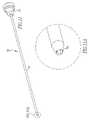
- FIG. 10shows an isometric view of an obturator of the present disclosure.
- FIG. 10Ashows an enlarged view of a distal portion of the obturator of FIG. 10 .
- FIG. 11shows an isometric view of an alternative embodiment of the obturator of FIG. 10 .
- FIG. 11Ashows an enlarged view of a distal portion of the obturator of FIG. 11 .
- FIG. 12shows a side view of an alternative embodiment of the obturator of FIG. 10 .
- FIG. 12Ashows an enlarged view of a distal portion of the obturator of FIG. 12 .
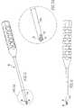
- FIG. 13shows an isometric view of a drill bit of the present disclosure.
- FIG. 13Ashows an enlarged view of a distal portion of the drill bit of FIG. 13 .
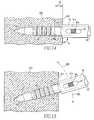
- FIG. 14shows a side view of anchor delivery into a bone by the anchor delivery system of FIG. 8 .
- FIG. 15shows a side view of an alternative anchor delivery into a bone by the anchor delivery system of FIG. 8 .
- FIG. 1shows a guide 10 of the present disclosure.
- the guide 10includes a shaft 11 coupled to a handle 12 .
- a central passage 13extends through the shaft 11 and the handle 12 for receiving a drill and an anchor delivery tool, as described in more detail below.
- the shaft 11includes a proximal portion 11 a and a distal portion 11 b .
- the distal portion 11 bshown in FIG. 1 A, includes a V-shaped tip 14 and an open side window 15 .
- the windows 15are located as distal as possible as the space to view them arthroscopically is small in some joints, such as the hip.
- the windows 15may be located more or less distal.
- the proximal portion 11 ais coupled to the handle 12 and partially extends a length of the handle 12 .
- the handle 12includes a body 12 a , a tapered distal portion 12 b , and a flat proximal portion 12 c . Having a flat proximal portion 12 c allows a surgeon to visualize the depth that a drill and anchor are advanced into bone, thereby substantially reducing the possibility of parallax and other depth control issues that may be found in other designs, as further described below.
- having a tapered distal portion 12 ballows a surgeon to impart deeper penetration of the guide 10 into a body, if needed, during surgery, as will be further described below.
- the distal 12 b and proximal 12 c portionsmay be of a shape other than tapered or flat.
- the body 12 aincludes circumferentially extending ribs 16 along a length of the body 12 a for maintaining a grip on the handle 12 while imparting axial compression and bending into the guide 10 during surgery, as will be further described below.
- Other means for maintaining a gripknown to one of ordinary skill in the art, may be used.
- the guide 10also includes a longitudinal axis 17 along its length.
- the guide 10includes a high strength material, such as a high strength stainless steel material, in order to substantially reduce the possibility of plastic deformation of the guide 10 when it is subjected to various bending forces during surgery, as will be further described below.
- a high strength materialsuch as a high strength stainless steel material
- other high strength material known to one of ordinary skill in the artcan be used.
- FIG. 2shows an alternative embodiment of the guide 10 of FIG. 1 wherein the shaft 11 of the guide 10 is bent or curved relative to the longitudinal axis 17 of the guide 10 .
- the bend or curveis incorporated into the shaft 11 to direct the drill and an anchor on the anchor delivery tool around anatomy during surgery, especially anatomy that prevents a straight trajectory.
- FIGS. 3 and 4show an alternative embodiment of the guide 10 of FIG. 1 .
- the distal portion 21 b of the guide 20includes a forked tip 24 and an open side window 25 .
- FIGS. 5 and 6show another alternative embodiment of the guide 10 of FIG. 1 .
- the distal portion 31 b of the guide 30includes a crown-shaped tip 34 and open side windows 35 . Other shapes may be used for the tip of the distal portion of the shaft.
- FIG. 7shows the anchor delivery tool 40 and anchor 45 of the present disclosure
- FIGS. 8 and 9show the anchor delivery system 50 of the present disclosure
- the tool 40includes a shaft 41 and a handle 42 coupled to the shaft 41 .
- the shaft 41includes a proximal portion 41 a and a distal portion 41 b .
- the distal portion 41 bincludes an area of reduced diameter 43 and a tip 44 that extends from the distal portion 41 b .
- the area of reduced diameter 43includes a length of about 3 mm and is used for depth stop and relief purposes, as will be further described below.
- a laser mark 41 cis also located at the distal portion 41 b of the anchor delivery tool 40 for depth control purposes, as will be further described below.
- a suture anchor 45is coupled to the tip 44 of the tool 40 .
- the anchor 45includes an anchor body 45 a having an anchoring portion 45 b and a plug portion 45 c .
- the anchoring portion 45 bincludes at least two slots 45 d , extending a length of the anchoring portion 45 b , and laterally extending barbs 45 e .
- the plug portion 45 cincludes a passage 45 f that extends through the plug portion 45 c .
- a suture 46having two free ends 46 a , is disposed within the passage 45 f such that both ends 46 a are housed within the slots 45 d of the anchoring portion 45 b , as shown by the arrow 45 h pointing to the slots 45 d .
- the tip 44interfaces with an opening (not shown) in a proximal portion 45 g of the anchor 45 .
- the anchor 45is more fully explained in U.S. Provisional Patent Application 60/896,520, which is incorporated herein by reference in its entirety.
- the shaft 41also includes two channels 47 that extend from the area of reduced diameter 43 to the proximal portion 41 a .
- the two free ends 46 a of suture 46extend along a length of both the anchor 45 and the shaft 41 , are housed in the slots 45 d and channels 47 , and extend through a proximal portion 42 e of the handle 42 .
- the proximal portion 41 a of the shaft 41is coupled to the handle 42 .
- the handle 42includes a hub 42 a , a nose cone 48 coupled to the hub 42 a , and a knob 49 coupled to the hub 42 a and located between the nose cone 48 and the handle 42 .
- the handle 42further includes two suture retaining features 42 b , or tabs, for retaining suture 46 during surgery, as will be further described below, laterally extending ribs 42 c for maintaining a grip on the handle 42 while imparting axial compression during surgery, and a through passage 42 d .
- the nose cone 48includes a flat distal portion 48 a , a proximal portion 48 b , and a cavity 48 c .
- the nose cone 48includes a slotted opening 48 d for housing suture during surgery, as will be further described below, and a bore 48 e .
- the bore 48 eis sized such that the nose cone 48 tightly fits the hub 42 a .
- the knob 49includes a distal portion 49 a that is housed within the cavity 48 c when the distal portion 49 a is in a first position, as shown in FIGS. 7-9 and as will be further described below, a proximal portion 49 b , laterally extending wings 49 c , and a bore 49 h .
- the bore 49 his sized such that the knob 49 easily slides on the hub 42 a .
- the knob 49also includes a cavity 49 d that houses a spring 49 e for spring loading of the knob 49 against the nose cone 48 and for adjusting the knob 49 between a first position 49 f , as described above, and a second position 49 g , as more clearly shown in FIG. 9A .
- the ends 46 amay be wound around the tabs 42 b of the handle 42 , as represented by the arrows 42 b ′, and subsequently placed within the slotted opening 48 d to be retained between the knob 49 and the nose cone 48 during delivery of the anchor 45 into bone, as will be further described below.
- FIG. 10shows an obturator 60 that may be used for percutaneous introduction of the guide 10 into the body.
- the obturator 60includes a shaft 61 coupled to a handle 62 .
- the shaft 61includes a proximal portion 61 a and a distal portion 61 b .
- the distal portion 61 bincludes a conical, atraumatic tip 61 c for easier passage of the obturator 60 through the body.
- a through passage 61 dthat extends a length of the shaft 61 and is coaxial with a through passage 62 a that extends a length of the handle 62 .
- the obturator 60is inserted through the central passage 13 of the guide 10 and the combination is then passed over a previously implanted guide wire to be introduced into the body and delivered to the desired site for tissue repair. After delivery of the guide 10 into the body, the guide wire is removed.
- the obturator 60allows for easier percutaneous introduction of the guide 10 to a desired site within the body by filling the inner diameter of the central passage 13 and substantially reducing the possibility of the tip 14 from becoming caught on tissue within the body.
- FIGS. 11 and 12show alternative embodiments of the obturator 60 of FIG. 10 .
- the obturators 70 , 80do not include through passages extending the lengths of the shafts 71 , 81 and the handles 72 , 82 .
- the tip 71 c of the obturator 70 of FIG. 11has a conical, atraumatic shape, as more clearly shown in FIG. 11A .
- the obturator 80 of FIG. 12has a sharp, pointed tip 81 c , as more clearly shown in FIG. 12A .
- obturators 70 , 80 of FIGS. 11 and 12are not used for percutaneous introduction of the guide 10 into the body. Rather, obturators 70 , 80 are used for introduction of the guide 10 through the seal of a previously implanted cannula and subsequently into the body and to a desired site for tissue repair.
- the tip 14 of the guide 10is placed against the bone to stabilize the guide 10 , for subsequent drilling and anchor delivery, and the obturator 60 is then removed from the central passage 13 of the guide 10 .
- FIG. 13shows a drill bit 90 that may be used for drilling of a hole into a bone.
- the drill bit 90includes a shaft 91 having a proximal portion 91 a and a distal portion 91 b .
- a sharp, pointed tip 92extends from the distal portion 91 b of the shaft 91 .
- a laser mark 91 cis also located at the distal portion 91 b of the drill bit 90 for depth control purposes, as will be further described below.
- the proximal portion 91 aincludes a depth stop 93 and an attachment area 91 d for coupling of a drive unit (not shown) used to rotate the drill bit 90 and drill a hole into bone.
- the drill bit 90is inserted into the central passage 13 of the guide 10 and a drive unit (not shown) is coupled to the attachment area 91 d .
- the drive unitis then operated to rotate the drill bit 90 and drill a hole into the bone.
- the laser mark 91 c and the depth stop 93cooperate to control the depth of the hole such that the depth stop 93 abuts the flat proximal portion 12 c of the guide handle 12 at the same time that the laser mark 91 c becomes centered within the side windows 15 of the shaft 11 .
- full advancement of the drill bit 90 into the guide 10has occurred, drilling of the hole is finished, and the drill bit 90 is removed from the central passage 13 of the guide 10 .
- the anchor delivery tool 40is disposed within the central passage 13 of the guide 10 , as shown in FIGS. 8 and 9 , for delivery of the anchor 45 into the previously-drilled hole 100 , as shown in FIG. 14 .
- the anchor 45is advanced into the hole 100 in an axially-oriented manner by tapping on a proximal portion 42 e of the handle 42 . Similar to the drilling procedure described above, full advancement of the tool 40 into the guide 10 is achieved when the flat distal portion 48 a of the nose cone 48 abuts the flat proximal portion 12 c of the guide handle 12 . At this same time, the laser mark 41 c is centered within the side windows 15 of the shaft 11 .
- the distal portion 48 a of the nose cone 48 and the proximal portion 12 c of the guide handle 12are both flat in order to substantially reduce the visualization problems, such as parallax, and the resultant interpretation that is currently required for determining drill and anchor bone depths.
- FIG. 14shows the tool 40 located at an angle ⁇ , about 90°, relative to the surface 201 of the bone 200 upon placement of the anchor 45 into the bone 200 .
- ⁇about 90°
- the tool 40may be located at an angle of less or more than about 90 degrees relative to a surface 201 of the bone 200 , as represented by arrows 300 , 400 , upon placement of the anchor 45 in the bone 200 , and still deliver the anchor into the bone such that the proximal portion 45 g of the anchor 45 is positioned a distance of about 3 mm below a surface 201 of the bone 200 .
- the distal portion 41 b of the shaft 41includes an area of reduced diameter 43 having a length of about 3 mm.
- the area 43is included on the distal portion 41 b to substantially reduce the possibility of the distal portion 41 b from getting stuck in the hole 100 of the bone 200 during delivery of the anchor 45 into the hole 100 .
- the area 43can also serve as a depth stop, especially when the nose cone 48 is not used, to ensure that the proximal portion 45 g of the anchor 45 is positioned a distance of about 3 mm below a surface 201 of the bone 200 .
- the two free ends 46 a of suture 46are released from between the knob 49 and the nose cone 48 by moving the knob 49 toward the handle 42 and into a second position 49 g , as shown in FIG. 9 .
- the anchor delivery system 50is subsequently removed from the body, thereby leaving the anchor 45 and suture 46 in the bone.
- the suture 46is then used to secure a tissue to the bone 200 .
- the anchor 45includes a bioabsorbable polymer material.
- the anchor 45may be made from a biocompatible metal material, such as titanium.
- the shaft 41 and the through passage 42 dare sized such that the shaft 41 is press-fit into the through passage 42 d .
- the shaft 41 and the handle 42may be assembled in other ways.
- the shaft 41 and the handle 42may be assembled by heat staking, ultrasonic staking, spin welding, insert molding, or other methods known to one of ordinary skill in the art.
- the shaft 41includes stainless steel, but may be made from another biocompatible material known to one of ordinary skill in the art.
- the handle 41may include less than or more than two suture retaining features 42 b .
- the features 42 bare integral with the handle, but may be a separate component, and may be of any number of geometric shapes.
- the nose cone 48is insert molded to the shaft 41 .
- the hub 42 ais placed in a mold and the nose cone 48 is molded around the hub 42 a .
- the nose cone 48may be coupled to the hub 42 a by heat staking, ultrasonic staking, spin welding, or by any other method known to one of ordinary skill in the art.
- the nose cone 48 , knob 49 , suture retaining features 42 b , and handle 42include a non-metal material, but may include a metal material or other biocompatible material known to one of ordinary skill in the art.
- the laser marks 41 c , 91 cmay be any other type of visible mark and may be of a variety of widths.
- the shafts 61 , 71 , 81 and handles 62 , 72 , 82 of the obturators 60 , 70 , 80are made from stainless steel and plastic, respectively. However, either one could be made from any other biocompatible material known to one of ordinary skill in the art.
- the shafts 61 , 71 , 81are press-fit to the obturators 60 , 70 , 80 , but could be coupled to the obturators 60 , 70 , 80 by any other method known to one of ordinary skill in the art.
- the drill bit 90is made from stainless steel, but it could be made from any other biocompatible material known to one of ordinary skill in the art.
Landscapes
- Health & Medical Sciences (AREA)
- Life Sciences & Earth Sciences (AREA)
- Surgery (AREA)
- Orthopedic Medicine & Surgery (AREA)
- Medical Informatics (AREA)
- General Health & Medical Sciences (AREA)
- Biomedical Technology (AREA)
- Heart & Thoracic Surgery (AREA)
- Nuclear Medicine, Radiotherapy & Molecular Imaging (AREA)
- Molecular Biology (AREA)
- Animal Behavior & Ethology (AREA)
- Engineering & Computer Science (AREA)
- Public Health (AREA)
- Veterinary Medicine (AREA)
- Rheumatology (AREA)
- Dentistry (AREA)
- Oral & Maxillofacial Surgery (AREA)
- Surgical Instruments (AREA)
Abstract
Description
Claims (12)
Priority Applications (7)
| Application Number | Priority Date | Filing Date | Title |
|---|---|---|---|
| US11/839,721US8758367B2 (en) | 2006-09-05 | 2007-08-16 | Anchor delivery system |
| EP07871085.2AEP2187819B1 (en) | 2007-08-16 | 2007-09-20 | Anchor delivery system |
| JP2010520974AJP2010537676A (en) | 2007-08-16 | 2007-09-20 | Anchor delivery system |
| PCT/US2007/079027WO2009023034A1 (en) | 2007-08-16 | 2007-09-20 | Anchor delivery system |
| AU2007357651AAU2007357651B2 (en) | 2007-08-16 | 2007-09-20 | Anchor delivery system |
| US14/274,977US9572564B2 (en) | 2006-09-05 | 2014-05-12 | Anchor delivery system |
| US15/429,477US9931150B2 (en) | 2006-09-05 | 2017-02-10 | Anchor delivery system |
Applications Claiming Priority (2)
| Application Number | Priority Date | Filing Date | Title |
|---|---|---|---|
| US82457306P | 2006-09-05 | 2006-09-05 | |
| US11/839,721US8758367B2 (en) | 2006-09-05 | 2007-08-16 | Anchor delivery system |
Related Child Applications (1)
| Application Number | Title | Priority Date | Filing Date |
|---|---|---|---|
| US14/274,977DivisionUS9572564B2 (en) | 2006-09-05 | 2014-05-12 | Anchor delivery system |
Publications (2)
| Publication Number | Publication Date |
|---|---|
| US20080058816A1 US20080058816A1 (en) | 2008-03-06 |
| US8758367B2true US8758367B2 (en) | 2014-06-24 |
Family
ID=39563300
Family Applications (3)
| Application Number | Title | Priority Date | Filing Date |
|---|---|---|---|
| US11/839,721Active2030-08-14US8758367B2 (en) | 2006-09-05 | 2007-08-16 | Anchor delivery system |
| US14/274,977ActiveUS9572564B2 (en) | 2006-09-05 | 2014-05-12 | Anchor delivery system |
| US15/429,477ActiveUS9931150B2 (en) | 2006-09-05 | 2017-02-10 | Anchor delivery system |
Family Applications After (2)
| Application Number | Title | Priority Date | Filing Date |
|---|---|---|---|
| US14/274,977ActiveUS9572564B2 (en) | 2006-09-05 | 2014-05-12 | Anchor delivery system |
| US15/429,477ActiveUS9931150B2 (en) | 2006-09-05 | 2017-02-10 | Anchor delivery system |
Country Status (5)
| Country | Link |
|---|---|
| US (3) | US8758367B2 (en) |
| EP (1) | EP2187819B1 (en) |
| JP (1) | JP2010537676A (en) |
| AU (1) | AU2007357651B2 (en) |
| WO (1) | WO2009023034A1 (en) |
Cited By (19)
| Publication number | Priority date | Publication date | Assignee | Title |
|---|---|---|---|---|
| US20140155913A1 (en)* | 2012-12-05 | 2014-06-05 | Young Jae Kim | Method of improving elasticity of tissue of living body |
| US20160157852A1 (en)* | 2014-03-03 | 2016-06-09 | Tenjin LLC | Implant placement systems, devices and methods |
| US9480473B2 (en) | 2011-12-27 | 2016-11-01 | Y.Jacobs Medical Inc. | Knotless suture, and kit containing same |
| US20170172562A1 (en)* | 2015-12-16 | 2017-06-22 | Conmed Corporation | Knotless suture anchor and deployment device |
| US9717587B2 (en) | 2014-03-03 | 2017-08-01 | Tenjin LLC | Multiple implant constructions and fixation methods associated therewith |
| US9743652B2 (en)* | 2015-07-06 | 2017-08-29 | Sam E. Hodges | Fishing line knot tying device |
| US9770240B2 (en) | 2014-03-03 | 2017-09-26 | Tenjin LLC | Ceramic implant placement systems and superelastic suture retention loops for use therewith |
| US9782250B2 (en) | 2014-03-03 | 2017-10-10 | Tenjin LLC | Implant placement systems and one-handed methods for tissue fixation using same |
| US9795374B2 (en) | 2014-03-03 | 2017-10-24 | Tenjin LLC | Implant placement systems, devices, and methods |
| US9808234B2 (en) | 2011-03-07 | 2017-11-07 | Y. Jacobs Medical Inc. | Suture thread |
| US9907548B2 (en) | 2014-03-03 | 2018-03-06 | Tenjin LLC | Implant placement systems, devices and methods |
| USD832439S1 (en)* | 2017-03-13 | 2018-10-30 | Healthium Medtech Private Limited | Suture anchor dispenser with depression |
| US10178990B2 (en) | 2012-12-05 | 2019-01-15 | Y. Jacobs Medical Inc. | Apparatus for inserting surgical thread, and surgical procedure kit for inserting surgical thread comprising same |
| USD842471S1 (en)* | 2017-03-13 | 2019-03-05 | Healthium Medtech Private Limited | Suture anchor dispenser without depression |
| US10226320B2 (en) | 2013-12-06 | 2019-03-12 | Y.Jacobs Medical Inc. | Apparatus for inserting medical tube and surgical procedure kit for inserting medical tube, having same |
| US20220142636A1 (en)* | 2012-10-18 | 2022-05-12 | Smith & Nephew, Inc. | Flexible anchor delivery system |
| US11504224B2 (en) | 2014-03-03 | 2022-11-22 | Tenjin LLC | Implant placement systems and one-handed methods for tissue fixation using same |
| USD1030442S1 (en)* | 2022-04-21 | 2024-06-11 | Depuy Ireland Unlimited Company | Inserter handle |
| USD1031980S1 (en)* | 2021-11-01 | 2024-06-18 | Medos International Sarl | Anchor insertion device |
Families Citing this family (63)
| Publication number | Priority date | Publication date | Assignee | Title |
|---|---|---|---|---|
| US20100121355A1 (en) | 2008-10-24 | 2010-05-13 | The Foundry, Llc | Methods and devices for suture anchor delivery |
| EP2238914B1 (en)* | 2009-04-10 | 2015-05-20 | Arthrex, Inc. | Twist-in suture anchor |
| GB0907064D0 (en) | 2009-04-24 | 2009-06-03 | Grampian Health Board | Tissue anchor insertion system |
| WO2010132310A1 (en) | 2009-05-12 | 2010-11-18 | Foundry Newco Xi, Inc. | Methods and devices to treat diseased or injured musculoskeletal tissue |
| US20100292733A1 (en) | 2009-05-12 | 2010-11-18 | Foundry Newco Xi, Inc. | Knotless suture anchor and methods of use |
| US8840643B2 (en)* | 2009-07-02 | 2014-09-23 | Arthrex, Inc. | Segmented suture anchor |
| US8911474B2 (en) | 2009-07-16 | 2014-12-16 | Howmedica Osteonics Corp. | Suture anchor implantation instrumentation system |
| CA2713309C (en) | 2009-08-20 | 2013-07-02 | Howmedica Osteonics Corp. | Flexible acl instrumentation, kit and method |
| US20110106013A1 (en)* | 2009-10-30 | 2011-05-05 | DePuy Mikek, Inc. | Dual cannula system and method for partial thickness rotator cuff repair |
| US8523903B2 (en) | 2009-10-30 | 2013-09-03 | Depuy Mitek, Llc | Partial thickness rotator cuff repair system and method |
| US8672967B2 (en)* | 2009-10-30 | 2014-03-18 | Depuy Mitek, Llc | Partial thickness rotator cuff repair system and method |
| CN105326533B (en) | 2010-09-24 | 2017-12-08 | 斯博特威尔丁股份有限公司 | Apparatus and method for suture holdfast to be fixed in sclerous tissues |
| US10092303B2 (en)* | 2010-10-06 | 2018-10-09 | Smith & Nephew, Inc. | System for use in tissue repair |
| JP5989759B2 (en)* | 2011-03-22 | 2016-09-07 | スミス アンド ネフュー インコーポレーテッド | Mooring system and feeding device for use with the mooring system |
| US20120245426A1 (en) | 2011-03-25 | 2012-09-27 | Salvas Paul L | Adjustable cannula |
| US9795398B2 (en) | 2011-04-13 | 2017-10-24 | Howmedica Osteonics Corp. | Flexible ACL instrumentation, kit and method |
| US9445803B2 (en) | 2011-11-23 | 2016-09-20 | Howmedica Osteonics Corp. | Filamentary suture anchor |
| US9788844B2 (en)* | 2011-12-16 | 2017-10-17 | Medos International Sarl | Methods and systems for attaching tissue to bone |
| US9808242B2 (en) | 2012-04-06 | 2017-11-07 | Howmedica Osteonics Corp. | Knotless filament anchor for soft tissue repair |
| AU2013277412B2 (en)* | 2012-06-18 | 2018-04-12 | Smith & Nephew, Inc. | Modular reamer retrograde attachment |
| US20140039552A1 (en) | 2012-08-03 | 2014-02-06 | Howmedica Osteonics Corp. | Soft tissue fixation devices and methods |
| DE102012220602A1 (en)* | 2012-11-13 | 2014-06-12 | Mathys Ag Bettlach | Surgical thread tensioning device |
| US9078740B2 (en) | 2013-01-21 | 2015-07-14 | Howmedica Osteonics Corp. | Instrumentation and method for positioning and securing a graft |
| US9402620B2 (en) | 2013-03-04 | 2016-08-02 | Howmedica Osteonics Corp. | Knotless filamentary fixation devices, assemblies and systems and methods of assembly and use |
| US9788826B2 (en) | 2013-03-11 | 2017-10-17 | Howmedica Osteonics Corp. | Filamentary fixation device and assembly and method of assembly, manufacture and use |
| US9463013B2 (en) | 2013-03-13 | 2016-10-11 | Stryker Corporation | Adjustable continuous filament structure and method of manufacture and use |
| US9526488B2 (en)* | 2013-03-15 | 2016-12-27 | Smith & Nephew, Inc. | Fenestrated locking suture anchor assembly |
| US10292694B2 (en) | 2013-04-22 | 2019-05-21 | Pivot Medical, Inc. | Method and apparatus for attaching tissue to bone |
| US10610211B2 (en) | 2013-12-12 | 2020-04-07 | Howmedica Osteonics Corp. | Filament engagement system and methods of use |
| US9833255B2 (en)* | 2013-12-26 | 2017-12-05 | Tenjin, Llc | Percussive surgical devices, systems, and methods of use thereof |
| JP6433673B2 (en)* | 2014-04-02 | 2018-12-05 | オリンパステルモバイオマテリアル株式会社 | Anchor fastener and fastening unit |
| US9986992B2 (en) | 2014-10-28 | 2018-06-05 | Stryker Corporation | Suture anchor and associated methods of use |
| US10568616B2 (en) | 2014-12-17 | 2020-02-25 | Howmedica Osteonics Corp. | Instruments and methods of soft tissue fixation |
| US10182808B2 (en)* | 2015-04-23 | 2019-01-22 | DePuy Synthes Products, Inc. | Knotless suture anchor guide |
| EP3383281B1 (en) | 2015-12-04 | 2024-01-24 | Crossroads Extremity Systems, LLC | Devices for anchoring tissue |
| USD805379S1 (en)* | 2016-03-11 | 2017-12-19 | Engineered Products And Services, Inc. | Masking plug |
| USD803115S1 (en)* | 2016-06-09 | 2017-11-21 | Enrique J. Baiz | Gear shift knob |
| USD793217S1 (en)* | 2016-07-14 | 2017-08-01 | Enrique J. Baiz | Lug nut |
| USD792203S1 (en)* | 2016-07-14 | 2017-07-18 | Enrique J. Baiz | Lug nut |
| USD793218S1 (en)* | 2016-08-11 | 2017-08-01 | Frank J. Hodges | Lugnut |
| USD792204S1 (en)* | 2016-08-17 | 2017-07-18 | Enrique J. Baiz | Lug nut |
| USD793220S1 (en)* | 2016-08-26 | 2017-08-01 | Enrique J. Baiz | Lug nut cap |
| USD793219S1 (en)* | 2016-08-26 | 2017-08-01 | Enrique J. Baiz | Lug nut cap |
| USD842671S1 (en)* | 2016-09-09 | 2019-03-12 | Enrique J. Baiz | Lug nut |
| USD792205S1 (en)* | 2016-09-09 | 2017-07-18 | Enrique J. Baiz | Lug nut |
| USD793854S1 (en)* | 2016-09-19 | 2017-08-08 | Enrique J. Baiz | Lug nut cap |
| USD792206S1 (en)* | 2016-09-19 | 2017-07-18 | Enrique J. Baiz | Lug nut cap |
| USD793221S1 (en)* | 2016-09-19 | 2017-08-01 | Enrique J. Baiz | Lug nut cap |
| US10582925B2 (en) | 2017-02-06 | 2020-03-10 | Medos International Sarl | Devices, systems, and methods for knotless suture anchors |
| USD902405S1 (en) | 2018-02-22 | 2020-11-17 | Stryker Corporation | Self-punching bone anchor inserter |
| USD864170S1 (en)* | 2018-03-26 | 2019-10-22 | Viablue Gmbh | Spike for a loudspeaker |
| US10631850B2 (en)* | 2018-05-23 | 2020-04-28 | Smith & Nephew, Inc. | Axially-complaint driver assembly |
| US12133639B1 (en)* | 2018-07-10 | 2024-11-05 | Tyber Medical Llc | Interchangeable tool handle |
| US11554197B2 (en)* | 2018-11-20 | 2023-01-17 | BioMark, LLC | Device with an open cell element |
| EP4076218A4 (en)* | 2019-12-19 | 2024-02-28 | LMF Industries Pty Ltd | Device for meniscal repair |
| US11389154B1 (en) | 2021-04-08 | 2022-07-19 | Integrity Orthopaedics, Inc. | Knotless micro suture anchor array for high density anatomical attachment of soft tissue to bone |
| US11382611B1 (en) | 2021-04-08 | 2022-07-12 | Integrity Orthopaedics, Inc. | Knotless micro-suture anchors and anchor arrays for anatomical attachment of soft tissue to bone |
| US11375992B1 (en) | 2021-04-08 | 2022-07-05 | Integrity Orthopaedics, Inc. | Cartridge device for suture anchor and suture management during implantation of a micro suture anchor array |
| US12396839B2 (en) | 2021-04-08 | 2025-08-26 | Integrity Orthopaedics, Inc. | Method and apparatus for creating a seam-like anatomical low creep attachment of soft tissue to bone |
| US11382613B1 (en) | 2021-04-08 | 2022-07-12 | Integrity Orthopaedics, Inc. | Methods for transtendinous implantation of knotless micro suture anchors and anchor arrays |
| US12226307B2 (en) | 2021-04-08 | 2025-02-18 | Integrity Orthopaedics, Inc. | Individually lockable cinch loop micro suture anchor array for high density anatomical attachment of soft tissue to bone |
| US11375995B1 (en) | 2021-04-08 | 2022-07-05 | Integrity Orthopaedics, Inc. | Locking suture construct for tensioned suture to suture stitches in anchor arrays for attaching soft tissue to bone |
| US20240225631A1 (en)* | 2023-01-05 | 2024-07-11 | Aevumed, Inc. | Labral Anchor System and Method |
Citations (18)
| Publication number | Priority date | Publication date | Assignee | Title |
|---|---|---|---|---|
| WO1982002824A1 (en) | 1981-02-17 | 1982-09-02 | United States Surgical Corp | Indicator for surgical stapler |
| US4920958A (en) | 1986-11-05 | 1990-05-01 | Minnesota Mining And Manufacturing Company | Drill guide assembly |
| US5037422A (en) | 1990-07-02 | 1991-08-06 | Acufex Microsurgical, Inc. | Bone anchor and method of anchoring a suture to a bone |
| US5690677A (en) | 1994-02-17 | 1997-11-25 | Arthrex, Inc. | Method for installing a suture anchor through a cannulated tissue-shifting guide |
| US5713905A (en) | 1993-09-15 | 1998-02-03 | Mitek Surgical Products, Inc. | Modular drill and method for using the same |
| US5782862A (en) | 1996-07-01 | 1998-07-21 | Bonutti; Peter M. | Suture anchor inserter assembly and method |
| US5827291A (en) | 1996-11-05 | 1998-10-27 | Linvatec Corporation | Suture anchor driver with suture retainer |
| US5868789A (en) | 1997-02-03 | 1999-02-09 | Huebner; Randall J. | Removable suture anchor apparatus |
| US5944739A (en)* | 1998-03-12 | 1999-08-31 | Surgical Dynamics, Inc. | Suture anchor installation system |
| US5948001A (en)* | 1996-10-03 | 1999-09-07 | United States Surgical Corporation | System for suture anchor placement |
| US5948000A (en)* | 1996-10-03 | 1999-09-07 | United States Surgical Corporation | System for suture anchor placement |
| US5951559A (en)* | 1996-07-25 | 1999-09-14 | Arthrex, Inc. | Method for installing a threaded suture anchor with a cannulated suture anchor drill guide |
| US6146385A (en) | 1997-02-11 | 2000-11-14 | Smith & Nephew, Inc. | Repairing cartilage |
| US6206886B1 (en) | 1996-05-03 | 2001-03-27 | William F. Bennett | Arthroscopic rotator cuff repair apparatus and method |
| US6402759B1 (en) | 1998-12-11 | 2002-06-11 | Biohorizons Implant Systems, Inc. | Surgical fastener driver |
| US20020188301A1 (en)* | 2001-06-11 | 2002-12-12 | Dallara Mark Douglas | Tissue anchor insertion system |
| US20030216768A1 (en)* | 2002-05-16 | 2003-11-20 | Norm Gitis | Multiportal device with linked segmented cannulae and method for percutaneous surgery |
| US20050240199A1 (en) | 2004-04-21 | 2005-10-27 | Jonathan Martinek | Suture anchor installation system and method |
Family Cites Families (7)
| Publication number | Priority date | Publication date | Assignee | Title |
|---|---|---|---|---|
| US5139520A (en)* | 1990-01-31 | 1992-08-18 | American Cyanamid Company | Method for acl reconstruction |
| US5258016A (en)* | 1990-07-13 | 1993-11-02 | American Cyanamid Company | Suture anchor and driver assembly |
| US5458608A (en)* | 1993-06-03 | 1995-10-17 | Surgin Surgical Instrumentation Inc. | Laparoscopic instruments and methods |
| CA2217406C (en)* | 1996-10-04 | 2006-05-30 | United States Surgical Corporation | Suture anchor installation system with disposable loading unit |
| US6146387A (en)* | 1998-08-26 | 2000-11-14 | Linvatec Corporation | Cannulated tissue anchor system |
| US7147641B2 (en)* | 2001-05-30 | 2006-12-12 | Chen Michael C | Fixation element insertion device |
| US20030125750A1 (en)* | 2001-11-05 | 2003-07-03 | Zwirnmann Ralph Fritz | Spring loaded fixation element insertion device |
- 2007
- 2007-08-16USUS11/839,721patent/US8758367B2/enactiveActive
- 2007-09-20JPJP2010520974Apatent/JP2010537676A/enactivePending
- 2007-09-20AUAU2007357651Apatent/AU2007357651B2/ennot_activeCeased
- 2007-09-20EPEP07871085.2Apatent/EP2187819B1/ennot_activeNot-in-force
- 2007-09-20WOPCT/US2007/079027patent/WO2009023034A1/enactiveApplication Filing
- 2014
- 2014-05-12USUS14/274,977patent/US9572564B2/enactiveActive
- 2017
- 2017-02-10USUS15/429,477patent/US9931150B2/enactiveActive
Patent Citations (19)
| Publication number | Priority date | Publication date | Assignee | Title |
|---|---|---|---|---|
| WO1982002824A1 (en) | 1981-02-17 | 1982-09-02 | United States Surgical Corp | Indicator for surgical stapler |
| US4920958A (en) | 1986-11-05 | 1990-05-01 | Minnesota Mining And Manufacturing Company | Drill guide assembly |
| US5037422A (en) | 1990-07-02 | 1991-08-06 | Acufex Microsurgical, Inc. | Bone anchor and method of anchoring a suture to a bone |
| US5713905A (en) | 1993-09-15 | 1998-02-03 | Mitek Surgical Products, Inc. | Modular drill and method for using the same |
| US5690677A (en) | 1994-02-17 | 1997-11-25 | Arthrex, Inc. | Method for installing a suture anchor through a cannulated tissue-shifting guide |
| US6206886B1 (en) | 1996-05-03 | 2001-03-27 | William F. Bennett | Arthroscopic rotator cuff repair apparatus and method |
| US5782862A (en) | 1996-07-01 | 1998-07-21 | Bonutti; Peter M. | Suture anchor inserter assembly and method |
| US5951559A (en)* | 1996-07-25 | 1999-09-14 | Arthrex, Inc. | Method for installing a threaded suture anchor with a cannulated suture anchor drill guide |
| US5948001A (en)* | 1996-10-03 | 1999-09-07 | United States Surgical Corporation | System for suture anchor placement |
| US5948000A (en)* | 1996-10-03 | 1999-09-07 | United States Surgical Corporation | System for suture anchor placement |
| US5827291A (en) | 1996-11-05 | 1998-10-27 | Linvatec Corporation | Suture anchor driver with suture retainer |
| US5868789A (en) | 1997-02-03 | 1999-02-09 | Huebner; Randall J. | Removable suture anchor apparatus |
| US6146385A (en) | 1997-02-11 | 2000-11-14 | Smith & Nephew, Inc. | Repairing cartilage |
| US5944739A (en)* | 1998-03-12 | 1999-08-31 | Surgical Dynamics, Inc. | Suture anchor installation system |
| US6402759B1 (en) | 1998-12-11 | 2002-06-11 | Biohorizons Implant Systems, Inc. | Surgical fastener driver |
| US20020188301A1 (en)* | 2001-06-11 | 2002-12-12 | Dallara Mark Douglas | Tissue anchor insertion system |
| US20030216768A1 (en)* | 2002-05-16 | 2003-11-20 | Norm Gitis | Multiportal device with linked segmented cannulae and method for percutaneous surgery |
| US20050240199A1 (en) | 2004-04-21 | 2005-10-27 | Jonathan Martinek | Suture anchor installation system and method |
| US7645293B2 (en)* | 2004-04-21 | 2010-01-12 | United States Surgical Corporation | Suture anchor installation system and method |
Non-Patent Citations (3)
| Title |
|---|
| International Search Report and Written Opinion for PCT/2007/079027 dated Jul. 21, 2008. |
| Office Action for corresponding AU patent application No. 2007357651 mailed Jan. 9, 2013. |
| Office Action for European Patent Application EP07 871 05.2-2310 mailed Sep. 19, 2011. |
Cited By (30)
| Publication number | Priority date | Publication date | Assignee | Title |
|---|---|---|---|---|
| US11103230B2 (en) | 2011-03-07 | 2021-08-31 | Y.Jacobs Medical Inc. | Suture thread |
| US9808234B2 (en) | 2011-03-07 | 2017-11-07 | Y. Jacobs Medical Inc. | Suture thread |
| US9848865B2 (en) | 2011-03-07 | 2017-12-26 | Y.Jacobs Medical Inc. | Suture thread |
| US9924937B2 (en) | 2011-12-27 | 2018-03-27 | Y.Jacobs Medical Inc. | Knotless suture, and kit containing same |
| US9480473B2 (en) | 2011-12-27 | 2016-11-01 | Y.Jacobs Medical Inc. | Knotless suture, and kit containing same |
| US11103232B2 (en) | 2011-12-27 | 2021-08-31 | Y.Jacobs Medical Inc. | Knotless suture, and kit containing same |
| US20220142636A1 (en)* | 2012-10-18 | 2022-05-12 | Smith & Nephew, Inc. | Flexible anchor delivery system |
| US10178990B2 (en) | 2012-12-05 | 2019-01-15 | Y. Jacobs Medical Inc. | Apparatus for inserting surgical thread, and surgical procedure kit for inserting surgical thread comprising same |
| US10010317B2 (en)* | 2012-12-05 | 2018-07-03 | Young Jae Kim | Method of improving elasticity of tissue of living body |
| US20140155913A1 (en)* | 2012-12-05 | 2014-06-05 | Young Jae Kim | Method of improving elasticity of tissue of living body |
| US11241303B2 (en) | 2013-12-06 | 2022-02-08 | Y.Jacobs Medical Inc. | Apparatus for inserting medical tube and surgical procedure kit for inserting medical tube, having same |
| US10226320B2 (en) | 2013-12-06 | 2019-03-12 | Y.Jacobs Medical Inc. | Apparatus for inserting medical tube and surgical procedure kit for inserting medical tube, having same |
| US9999496B2 (en) | 2014-03-03 | 2018-06-19 | Tenjin LLC | Multiple implant constructions and fixation methods associated therewith |
| US10548711B2 (en) | 2014-03-03 | 2020-02-04 | Tenjin LLC | Implant placement systems and one-handed methods for tissue fixation using same |
| US9795374B2 (en) | 2014-03-03 | 2017-10-24 | Tenjin LLC | Implant placement systems, devices, and methods |
| US9782250B2 (en) | 2014-03-03 | 2017-10-10 | Tenjin LLC | Implant placement systems and one-handed methods for tissue fixation using same |
| US11504224B2 (en) | 2014-03-03 | 2022-11-22 | Tenjin LLC | Implant placement systems and one-handed methods for tissue fixation using same |
| US10149752B2 (en) | 2014-03-03 | 2018-12-11 | Tenjin LLC | Implant placement systems and one-handed methods for tissue fixation using same |
| US9770240B2 (en) | 2014-03-03 | 2017-09-26 | Tenjin LLC | Ceramic implant placement systems and superelastic suture retention loops for use therewith |
| US20160157852A1 (en)* | 2014-03-03 | 2016-06-09 | Tenjin LLC | Implant placement systems, devices and methods |
| US9566060B2 (en)* | 2014-03-03 | 2017-02-14 | Tenjin LLC | Implant placement systems, devices and methods |
| US9907548B2 (en) | 2014-03-03 | 2018-03-06 | Tenjin LLC | Implant placement systems, devices and methods |
| US9717587B2 (en) | 2014-03-03 | 2017-08-01 | Tenjin LLC | Multiple implant constructions and fixation methods associated therewith |
| US9743652B2 (en)* | 2015-07-06 | 2017-08-29 | Sam E. Hodges | Fishing line knot tying device |
| US20170172562A1 (en)* | 2015-12-16 | 2017-06-22 | Conmed Corporation | Knotless suture anchor and deployment device |
| US11490884B2 (en)* | 2015-12-16 | 2022-11-08 | Conmed Corporation | Knotless suture anchor and deployment device |
| USD842471S1 (en)* | 2017-03-13 | 2019-03-05 | Healthium Medtech Private Limited | Suture anchor dispenser without depression |
| USD832439S1 (en)* | 2017-03-13 | 2018-10-30 | Healthium Medtech Private Limited | Suture anchor dispenser with depression |
| USD1031980S1 (en)* | 2021-11-01 | 2024-06-18 | Medos International Sarl | Anchor insertion device |
| USD1030442S1 (en)* | 2022-04-21 | 2024-06-11 | Depuy Ireland Unlimited Company | Inserter handle |
Also Published As
| Publication number | Publication date |
|---|---|
| AU2007357651B2 (en) | 2014-10-02 |
| JP2010537676A (en) | 2010-12-09 |
| US20080058816A1 (en) | 2008-03-06 |
| US9931150B2 (en) | 2018-04-03 |
| EP2187819A1 (en) | 2010-05-26 |
| WO2009023034A1 (en) | 2009-02-19 |
| EP2187819B1 (en) | 2018-11-07 |
| AU2007357651A1 (en) | 2009-02-19 |
| US20170151007A1 (en) | 2017-06-01 |
| US20140249578A1 (en) | 2014-09-04 |
| US9572564B2 (en) | 2017-02-21 |
Similar Documents
| Publication | Publication Date | Title |
|---|---|---|
| US9931150B2 (en) | Anchor delivery system | |
| US10849635B2 (en) | System for use in tissue repair | |
| CN110662493B (en) | Anchor conveying system | |
| US12016548B2 (en) | Suture anchor implantation instrumentation system | |
| KR101926339B1 (en) | Surgical nail | |
| US20090192545A1 (en) | Curved suture anchor guide and method of use | |
| US20100241124A1 (en) | Soft Tissue Manipulator Assembly | |
| US20180193040A1 (en) | Systems, devices, and methods for guiding surgical devices into bone | |
| TWI542317B (en) | Surgical nail |
Legal Events
| Date | Code | Title | Description |
|---|---|---|---|
| AS | Assignment | Owner name:SMITH & NEPHEW, INC., TENNESSEE Free format text:ASSIGNMENT OF ASSIGNORS INTEREST;ASSIGNORS:P, MARC J.;MURPHY, KEVIN;BLOUGH, REBECCA A.;AND OTHERS;REEL/FRAME:019847/0312;SIGNING DATES FROM 20070904 TO 20070918 Owner name:SMITH & NEPHEW, INC., TENNESSEE Free format text:ASSIGNMENT OF ASSIGNORS INTEREST;ASSIGNORS:P, MARC J.;MURPHY, KEVIN;BLOUGH, REBECCA A.;AND OTHERS;SIGNING DATES FROM 20070904 TO 20070918;REEL/FRAME:019847/0312 | |
| AS | Assignment | Owner name:SMITH & NEPHEW, INC., TENNESSEE Free format text:CORRECTIVE ASSIGNMENT TO CORRECT THE WE ARE RE-RECORDING TO CORRECT INVENTORS LAST NAMES ON THE COVER SHEET PREVIOUSLY RECORDED ON REEL 019847 FRAME 0312;ASSIGNORS:PHILIPPON, MARC J.;MURPHY, KEVIN;BLOUGH, REBECCA A.;AND OTHERS;REEL/FRAME:019863/0614;SIGNING DATES FROM 20070904 TO 20070918 Owner name:SMITH & NEPHEW, INC., TENNESSEE Free format text:CORRECTIVE ASSIGNMENT TO CORRECT THE WE ARE RE-RECORDING TO CORRECT INVENTORS LAST NAMES ON THE COVER SHEET PREVIOUSLY RECORDED ON REEL 019847 FRAME 0312. ASSIGNOR(S) HEREBY CONFIRMS THE ASSIGNMENT;ASSIGNORS:PHILIPPON, MARC J.;MURPHY, KEVIN;BLOUGH, REBECCA A.;AND OTHERS;SIGNING DATES FROM 20070904 TO 20070918;REEL/FRAME:019863/0614 | |
| AS | Assignment | Owner name:UNIVERSITY OF WASHINGTON,WASHINGTON Free format text:ASSIGNMENT OF ASSIGNORS INTEREST;ASSIGNOR:WAHL, CHRISTOPHER J., DR.;REEL/FRAME:024449/0766 Effective date:20100512 Owner name:UNIVERSITY OF WASHINGTON, WASHINGTON Free format text:ASSIGNMENT OF ASSIGNORS INTEREST;ASSIGNOR:WAHL, CHRISTOPHER J., DR.;REEL/FRAME:024449/0766 Effective date:20100512 | |
| AS | Assignment | Owner name:UNIVERSITY OF WASHINGTON,WASHINGTON Free format text:ASSIGNMENT OF ASSIGNORS INTEREST;ASSIGNOR:WAHL, CHRISTOPHER J., DR.;REEL/FRAME:024565/0908 Effective date:20100614 Owner name:UNIVERSITY OF WASHINGTON, WASHINGTON Free format text:ASSIGNMENT OF ASSIGNORS INTEREST;ASSIGNOR:WAHL, CHRISTOPHER J., DR.;REEL/FRAME:024565/0908 Effective date:20100614 | |
| STCF | Information on status: patent grant | Free format text:PATENTED CASE | |
| MAFP | Maintenance fee payment | Free format text:PAYMENT OF MAINTENANCE FEE, 4TH YEAR, LARGE ENTITY (ORIGINAL EVENT CODE: M1551) Year of fee payment:4 | |
| MAFP | Maintenance fee payment | Free format text:PAYMENT OF MAINTENANCE FEE, 8TH YEAR, LARGE ENTITY (ORIGINAL EVENT CODE: M1552); ENTITY STATUS OF PATENT OWNER: LARGE ENTITY Year of fee payment:8 |