US8758264B2 - Expandable device for full thickness biopsy - Google Patents
Expandable device for full thickness biopsyDownload PDFInfo
- Publication number
- US8758264B2 US8758264B2US13/534,209US201213534209AUS8758264B2US 8758264 B2US8758264 B2US 8758264B2US 201213534209 AUS201213534209 AUS 201213534209AUS 8758264 B2US8758264 B2US 8758264B2
- Authority
- US
- United States
- Prior art keywords
- expandable
- plate member
- blade
- cable
- housing
- Prior art date
- Legal status (The legal status is an assumption and is not a legal conclusion. Google has not performed a legal analysis and makes no representation as to the accuracy of the status listed.)
- Active, expires
Links
- 238000001574biopsyMethods0.000titleclaimsabstractdescription68
- 238000000034methodMethods0.000claimsabstractdescription15
- 239000000523sampleSubstances0.000claims6
- 210000001519tissueAnatomy0.000description53
- 239000000463materialSubstances0.000description3
- 230000002496gastric effectEffects0.000description2
- HLXZNVUGXRDIFK-UHFFFAOYSA-Nnickel titaniumChemical compound[Ti].[Ti].[Ti].[Ti].[Ti].[Ti].[Ti].[Ti].[Ti].[Ti].[Ti].[Ni].[Ni].[Ni].[Ni].[Ni].[Ni].[Ni].[Ni].[Ni].[Ni].[Ni].[Ni].[Ni].[Ni]HLXZNVUGXRDIFK-UHFFFAOYSA-N0.000description2
- 229910001000nickel titaniumInorganic materials0.000description2
- 229910001220stainless steelInorganic materials0.000description2
- 239000010935stainless steelSubstances0.000description2
- 206010028980NeoplasmDiseases0.000description1
- 230000005856abnormalityEffects0.000description1
- 201000011510cancerDiseases0.000description1
- 201000010099diseaseDiseases0.000description1
- 208000037265diseases, disorders, signs and symptomsDiseases0.000description1
- 238000011156evaluationMethods0.000description1
- 210000000609gangliaAnatomy0.000description1
- 238000003780insertionMethods0.000description1
- 230000037431insertionEffects0.000description1
- 238000012977invasive surgical procedureMethods0.000description1
- 238000004519manufacturing processMethods0.000description1
- 230000004899motilityEffects0.000description1
- 210000003205muscleAnatomy0.000description1
- 230000001537neural effectEffects0.000description1
Images


Classifications
- A—HUMAN NECESSITIES
- A61—MEDICAL OR VETERINARY SCIENCE; HYGIENE
- A61B—DIAGNOSIS; SURGERY; IDENTIFICATION
- A61B10/00—Instruments for taking body samples for diagnostic purposes; Other methods or instruments for diagnosis, e.g. for vaccination diagnosis, sex determination or ovulation-period determination; Throat striking implements
- A61B10/02—Instruments for taking cell samples or for biopsy
- A61B10/04—Endoscopic instruments, e.g. catheter-type instruments
Definitions
- Full thickness gastric wall biopsiesthat include the entire muscularis basement would be helpful to evaluate a number of diseases including motility abnormalities and cancer.
- Current mucosal-based biopsiesare insufficient as they do not allow evaluation of the deep muscle layers or neural tissue including ganglia present in the deep layers.
- most full thickness biopsiesrequire invasive surgical procedures to access the gastric wall and other deep tissue areas.
- an expandable biopsy devicein one aspect, includes an expandable portion including an expandable plate member and a cable operably connected to the expandable plate member.
- the expandable plate memberhas a substantially flattened configuration and an expanded configuration where the expanded configuration is longitudinally elongated relative to the flattened configuration.
- the flattened configurationhas a first diameter.
- the expandable biopsy devicealso includes a cutting portion including a blade and a housing. The blade is positionable at least partially within the housing and the blade has a second diameter.
- the housingincludes an opening and a cavity formed within housing. The second diameter of the blade is greater than the first diameter of the expandable plate member in the substantially flattened configuration.
- a method of obtaining a biopsy sampleincludes positioning an expandable portion of a biopsy device at a tissue site.
- the expandable portionincludes an expandable plate member and a cable operably connected to the expandable plate member where the expandable plate member has a substantially flattened configuration and an expanded configuration.
- the methodfurther includes inserting the expandable plate member into the tissue site in the expanded configuration and proximally pulling on the cable and positioning the expandable plate member in the flattened configuration at the tissue site.
- the methodalso includes advancing a cutting portion of the biopsy device toward the tissue site over the cable, advancing a blade of the cutting portion to the tissue site and cutting the tissue sample while holding the expandable plate member against the tissue sample in the flattened configuration.
- FIG. 1is a perspective view of an expandable biopsy device in accordance with an embodiment of the present invention
- FIG. 2is a partial perspective view of an expandable portion of the expandable biopsy device shown in FIG. 1 in an expanded configuration
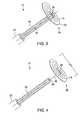
- FIG. 3is a partial perspective view of the expandable portion of the expandable biopsy device in a flattened configuration
- FIG. 4is a partial perspective view of an embodiment of the expandable portion of the expandable biopsy device in a flattened configuration
- FIG. 5is a perspective view of an embodiment of a cutting portion of the expandable biopsy device shown in FIG. 1 ;
- FIG. 6is a perspective view of an embodiment of the cutting portion of the expandable biopsy device
- FIG. 7is a perspective view of an embodiment of the cutting portion of the expandable biopsy device
- FIG. 8is a partial side view of a blade of the cutting portion in accordance with an embodiment of the present invention.
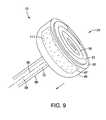
- FIG. 9is a perspective view of an embodiment of an expandable biopsy device in accordance with the present invention.
- FIGS. 10-17illustrate operation of an embodiment of the expandable biopsy device.
- proximal and distalshould be understood as being in the terms of a physician delivering the expandable biopsy device to a patient.
- distalmeans the portion of the expandable biopsy device that is farthest from the physician and the term “proximal” means the portion of the expandable biopsy device that is nearest to the physician.
- FIG. 1illustrates an embodiment of an expandable biopsy device 10 in accordance with the present invention.
- the expandable biopsy device 10includes an expandable portion 12 and a cutting portion 14 .
- the expandable portion 12is also shown in FIGS. 2-4 .
- the expandable portion 12includes an expandable plate member 18 .
- the expandable plate member 18has an expanded configuration 20 shown in FIGS. 1 and 2 .
- the expanded configuration 20may be spiral shaped and at least partially wound around a shaft 26 .
- the expandable plate member 18also has a flattened configuration 22 shown in FIGS. 3 and 4 .
- the expanded configuration 20 of the expandable plate member 18is longitudinally expanded relative to the flattened configuration 22 so that a length L 1 in the expanded configuration is greater than a length L 2 of the expandable plate member 18 in the flattened configuration 22 .
- the expandable plate member 18forms a substantially flat sheet of material that may be used supporting the tissue at the biopsy site.
- the expandable plate member 18may be made from any material suitable for use in a patient and having sufficient strength to extend through a tissue.
- the expandable plate membermay be made from nitinol or stainless steel.
- the expandable plate member 18may formed in the expanded configuration 20 and delivered to a biopsy site in the expanded configuration 20 and then transitioned to the flattened configuration 22 once the expandable plate member 18 has been extended through the tissue to be biopsied as explained in more detail below.
- the expandable plate member 18has a first diameter D 1 measured at the widest part of the expandable plate member 18 in the expanded configuration 20 .
- the expandable plate member 18has a second diameter D 2 in the flattened configuration 22 . In some embodiments, D 2 is greater than D 1 .
- the expandable plate member 18may be removably attached to the shaft 26 .
- the shaft 26may be a cable such as a torque cable suitable for rotatably inserting the expandable plate member 18 in the expanded configuration 20 through the tissue for obtaining a biopsy sample.
- a catheter 27may also be provided to cover the shaft 26 so that the shaft 26 does not contact or injure the surrounding tissue as the shaft 26 is rotated to advance the expandable plate member 18 through the tissue.
- the catheter 27may extend the full length of the shaft 26 or over a portion of the shaft 26 .
- the shaft 26may be removably attached to the expandable plate member 18 near or at a center portion 30 of the expandable plate member 18 .
- the center portion 30may include a tip 32 that may be pointed in some embodiments to facilitate insertion of the expandable plate member 18 into the tissue.
- the shaft 26includes a lumen 28 extending at least partially through the shaft 26 as shown in FIG. 4 . As shown in FIG. 3 , the expandable plate member 18 may be collapsed to the flattened configuration 22 after the shaft 26 has been rotated to pass the expandable plate member 18 through the tissue. The shaft 26 may then be removed from the expandable plate member 18 as shown in FIG. 4 .
- a cable 36may be connected to the expandable plate member 18 .
- the cable 36may be any kind of cable including sutures and wires and the like.
- the cable 36may be monofilament, braided, twisted or multifilament.
- the cable 36may be attached to the expandable plate member 18 by any method known to one skilled in the art.
- the cable 36may be welded, soldered, glued, taped and the like to the expandable plate member 18 .
- the cable 36is illustrated in FIG. 2 connected to the center portion 30 of the expandable plate member 18 .
- the cable 36may be extended through the lumen 28 of the shaft 26 and connected to a handle (not shown) for controlling the movement of the cable 36 . As shown in FIG.
- the cable 36may remain connected to the expandable plate member 18 when the shaft 26 is removed.
- the cable 36may be used to facilitate flattening of the expandable plate member 18 to the flattened configuration 22 and for removal of the tissue sample as described in more detail below.
- a guide wire 40may be used to the position the expandable portion 12 of the biopsy device 10 at the biopsy site.
- the biopsy device 10also includes the cutting portion 14 that is shown in FIGS. 1 and 5 - 7 .
- the cutting portion 14includes a blade 44 that may be movably positionable in a housing 46 .
- the housing 46includes an opening 51 and a cavity 47 formed in the housing 46 that is sized and shaped to hold the biopsy sample after the sample has been removed from the patient.
- the blade 44may be moved to an exposed position 48 shown in FIGS. 6 and 7 where at least an edge 50 the blade 44 is extended distal to a distal end 52 of the housing 46 so that the blade 44 may contact the tissue.
- the edge 50 of the blade 44is configured to cut the tissue to obtain a biopsy sample.
- the blade 44may be releasably locked in position relative to the housing 46 .
- the blade 44may be a single blade having a single cutting edge 54 as shown in FIG. 6 or the blade 44 may include a plurality of blade having a plurality of cutting edges 54 as shown in FIG. 7 . Additional blade configurations may also be used including alternatively shaped cutting edges, straight edges, beveled edges and multiple blades, by way of non-limiting example.
- the blade 44may be include the cutting edge 54 around a perimeter 56 of the blade 44 or the blade 44 may include cutting edges 54 and non-cutting portions 58 where the housing 46 and the blade 44 or the blade 44 alone may be rotated to complete cutting a removable portion of tissue, see by way of non-limiting example, FIG. 8 .
- the perimeter 56 of the blade 44may be circular, oval, rectangular, square, or any other shape.
- the shape of the housing 46may be the same as the shape of the perimeter 56 or different.
- the blade 44has a diameter D 3 measured at the widest portion of the blade 44 .
- the diameter D 3 of the blade 44is sized and shaped to be larger than the diameter D 2 of the expandable plate member 18 in the flattened configuration 22 so that the blade 44 cuts around the tissue supported by the expandable plate member 18 as explained in more detail below.
- the diameter D 3may be from about 0.5 mm to about 2 cm, although other diameters may also be used.
- the blade 44may be made from any material suitable for use in a patient and having sufficient strength to extend through a tissue.
- the blade 44may be made from nitinol or stainless steel.
- the blade 44may also be positioned in a protected position 60 as shown in FIG. 5 where the edge 50 of the blade 44 is positioned proximal to the distal edge 52 of the housing 46 so the blade 44 is not exposed to the tissue.
- the blade 44may be positioned in the protected position 60 for delivery to the biopsy site and after the biopsy sample has been obtained for removal from the patient.
- the blade 44may be releasably locked in the protected position 60 .
- the cutting portion 14may also include a shaft 66 configured to move the housing 46 within the patient.
- the shaft 66includes a lumen 68 extending at least partially through the shaft 66 .
- a drive cable 72 for movably positioning the blade 44may extend through the lumen 68 of the shaft 66 as shown in FIGS. 5 and 6 .
- the drive cable 72may be a torque cable suitable for rotating the blade 44 to cut into the tissue to obtain the biopsy sample.
- the drive cable 72may also facilitate placement of the blade 44 against the tissue in the proper relationship to the expandable plate member 18 so that the blade 44 cuts around a perimeter 39 of the expandable plate member 18 that has been flattened against the tissue to be biopsied.
- FIG. 9illustrates the expandable plate member 18 in the flattened configuration 22 and positioned within the opening 51 of the housing 46 after a full thickness biopsy sample 111 has been removed from the patient and is contained within the cavity 47 of the housing 46 .
- the blade 44has been positioned proximal to the distal end 52 of the housing 46 and the expandable plate member 18 forms a cover over the cavity 47 to hold the sample in position as the biopsy device 10 is withdrawn from the patient.
- the cable 36is connected to the expandable plate member 18 to place tension on the expandable plate member 18 to hold the expandable plate member 18 in the flattened configuration 22 while the biopsy device 10 is being withdrawn.
- the cable 36is extended through the lumen 68 of the shaft 66 .
- the cable 36may be external to the lumen 68 or in a rapid exchange configuration.
- FIGS. 10-17Operation of the expandable biopsy device will be explained with reference to the expandable biopsy device 10 as an example. Operation of the expandable biopsy device 10 is shown in FIGS. 10-17 .
- FIG. 10illustrates a tissue 110 of a patient where a full thickness biopsy through the tissue wall 110 is to be taken. A distal end 102 of an endoscope is shown with a wire guide 40 being directed to the tissue 110 .
- FIG. 11illustrates the expandable portion 12 of the biopsy device 10 that has been back loaded into the endoscope 100 and is being delivered to the tissue 110 over the guide wire 40 .
- the expandable plate member 18is in the expanded configuration 20 as the expandable portion 12 is being delivered to the tissue 110 .
- the expandable portion 12may be delivered over the cable 36 to the biopsy site at the tissue 110 .
- the cable 36may have been previously secured to the tissue 110 .
- FIG. 12illustrates the expandable plate member 18 being rotatably positioned through the tissue wall 110 by rotation of the shaft 26 . (Endoscope no longer shown.)
- a proximal portion of the shaft 26may be connected to a rotatable handle (not shown) to drive the shaft 26 so that the tip 30 enters the tissue 110 and the remaining portion of the expandable plate member 18 enters and extends through the full thickness of the tissue 110 .
- the catheter 27is also shown positioned of the shaft 26 to protect the patient while the shaft 26 is rotatably advanced.
- FIG. 13illustrates the expandable plate member 18 fully advanced through the tissue 110 and positioned in the flattened configuration 22 against the tissue 110 .
- the cable 36may be tensioned to pull the expandable plate member 18 in the flattened configuration 22 and against the tissue 110 .
- the shaft 26is shown being proximally withdrawn from the expandable plate member 18 . Once the shaft 26 is withdrawn, the cutting portion 14 of the biopsy device 10 may be back loaded into the endoscope for delivery to the biopsy site.
- FIG. 14illustrates the cutting portion 14 being distally advanced to the tissue 110 over the cable 36 .
- the blade 44is in the protected position 60 within the housing 46 .
- the shaft 66may be used to advance the housing 46 and the blade 44 to the tissue 110 .
- the blade 44in the exposed position 48 extended distal to the housing 46 and adjacent the tissue 110 .
- the expandable plate member 18is in the flattened configuration 22 and tension may be placed on the cable 36 to pull the expandable plate member 18 against the tissue 110 as the blade 44 is being advanced into the tissue 110 to cut a biopsy sample.
- the blade 44may be rotatably advanced through the tissue 110 , for example by connecting the cable 72 to a drill or rotatable handle.
- the shaft 66protects the surrounding tissue from the rotating cable 72 .
- FIG. 16illustrates the blade 44 that has cut through the tissue 110 and around the circumference 39 of the expandable plate member 18 .
- the expandable plate member 18is tensioned against the tissue 110 in the flattened configuration 22 to hold and support the tissue 110 as the blade 44 cuts through the full thickness of the tissue 110 .
- FIG. 17illustrates the removal of a full thickness biopsy sample 111 from the tissue 110 .
- the expandable plate member 18is in the flattened configuration 22 and is positioned within the opening 51 of the housing 46 to hold the sample 111 within the cavity 47 of the housing.
- the cable 36 and the shaft 66are withdrawn proximally from the site of the tissue to remove the housing 46 and the expandable plate member 18 .
- the expandable plate member 18can be withdrawn from the patient in the flattened configuration 22 .
- the flattened configuration 22allows the expandable plate member 18 to serve as a cover for the cavity 47 of the housing 46 .
Landscapes
- Health & Medical Sciences (AREA)
- Surgery (AREA)
- Life Sciences & Earth Sciences (AREA)
- Heart & Thoracic Surgery (AREA)
- Molecular Biology (AREA)
- Radiology & Medical Imaging (AREA)
- Engineering & Computer Science (AREA)
- Biomedical Technology (AREA)
- Nuclear Medicine, Radiotherapy & Molecular Imaging (AREA)
- Medical Informatics (AREA)
- Pathology (AREA)
- Animal Behavior & Ethology (AREA)
- General Health & Medical Sciences (AREA)
- Public Health (AREA)
- Veterinary Medicine (AREA)
- Surgical Instruments (AREA)
- Sampling And Sample Adjustment (AREA)
Abstract
Description
Claims (19)
Priority Applications (1)
| Application Number | Priority Date | Filing Date | Title |
|---|---|---|---|
| US13/534,209US8758264B2 (en) | 2011-06-29 | 2012-06-27 | Expandable device for full thickness biopsy |
Applications Claiming Priority (2)
| Application Number | Priority Date | Filing Date | Title |
|---|---|---|---|
| US201161502581P | 2011-06-29 | 2011-06-29 | |
| US13/534,209US8758264B2 (en) | 2011-06-29 | 2012-06-27 | Expandable device for full thickness biopsy |
Publications (2)
| Publication Number | Publication Date |
|---|---|
| US20130006141A1 US20130006141A1 (en) | 2013-01-03 |
| US8758264B2true US8758264B2 (en) | 2014-06-24 |
Family
ID=47391334
Family Applications (1)
| Application Number | Title | Priority Date | Filing Date |
|---|---|---|---|
| US13/534,209Active2032-12-22US8758264B2 (en) | 2011-06-29 | 2012-06-27 | Expandable device for full thickness biopsy |
Country Status (1)
| Country | Link |
|---|---|
| US (1) | US8758264B2 (en) |
Cited By (1)
| Publication number | Priority date | Publication date | Assignee | Title |
|---|---|---|---|---|
| US20180249987A1 (en)* | 2013-11-20 | 2018-09-06 | Covidien Lp | Devices, systems, and methods for navigating a biopsy tool to a target location and obtaining a tissue sample using the same |
Families Citing this family (1)
| Publication number | Priority date | Publication date | Assignee | Title |
|---|---|---|---|---|
| EP3338646A1 (en) | 2016-12-21 | 2018-06-27 | National University of Ireland Galway | A biopsy device |
Citations (28)
| Publication number | Priority date | Publication date | Assignee | Title |
|---|---|---|---|---|
| US3732858A (en)* | 1968-09-16 | 1973-05-15 | Surgical Design Corp | Apparatus for removing blood clots, cataracts and other objects from the eye |
| US4706671A (en)* | 1985-05-02 | 1987-11-17 | Weinrib Harry P | Catheter with coiled tip |
| US4785826A (en)* | 1987-03-02 | 1988-11-22 | Ward John L | Biopsy instrument |
| US4935025A (en)* | 1989-01-30 | 1990-06-19 | Bundy Mark A | Transluminal lysing device |
| US5074311A (en)* | 1989-12-06 | 1991-12-24 | Hasson Harrith M | Biopsy device |
| US5573008A (en)* | 1993-10-29 | 1996-11-12 | Boston Scientific Corporation | Multiple biopsy sampling coring device |
| US5630805A (en)* | 1994-05-06 | 1997-05-20 | Ternamian; Artin M. | Method for accessing the peritoneal cavity |
| US5660186A (en)* | 1995-06-07 | 1997-08-26 | Marshfield Clinic | Spiral biopsy stylet |
| US6162203A (en)* | 1999-01-11 | 2000-12-19 | Haaga; John R. | Cargo delivery needle |
| US20020115943A1 (en)* | 1998-03-03 | 2002-08-22 | Senorx, Inc. | Sentinel node location and biopsy |
| US6544195B2 (en)* | 2000-03-04 | 2003-04-08 | Joseph F. Wilson | Tissue of foreign body extractor |
| US6626903B2 (en)* | 1997-07-24 | 2003-09-30 | Rex Medical, L.P. | Surgical biopsy device |
| US6827692B2 (en)* | 2000-07-24 | 2004-12-07 | Pietro Castellacci | Needle of the biopsy type or for taking other samples from human or animal organs |
| US20050010275A1 (en)* | 2002-10-11 | 2005-01-13 | Sahatjian Ronald A. | Implantable medical devices |
| US20050143674A1 (en)* | 1998-09-01 | 2005-06-30 | Burbank Fred H. | Methods and apparatus for securing medical instruments to desired locations in a patient's body |
| US20050209530A1 (en)* | 2001-03-23 | 2005-09-22 | Stryker Puerto Rico Limited | Micro-invasive tissue removal device |
| US6971988B2 (en)* | 2003-03-17 | 2005-12-06 | Tyco Healthcare Group, Lp | Endoscopic tissue removal apparatus and method |
| US7063671B2 (en)* | 2002-06-21 | 2006-06-20 | Boston Scientific Scimed, Inc. | Electronically activated capture device |
| US20080125798A1 (en)* | 2006-11-08 | 2008-05-29 | Cook Incorporated | Thrombus removal device |
| US20080234602A1 (en)* | 2007-03-19 | 2008-09-25 | Oostman Clifford A | Biological unit removal tools with retention mechanism |
| US20080294181A1 (en)* | 1996-02-02 | 2008-11-27 | The Regents Of The University Of California | Clot capture coil |
| US20090054805A1 (en)* | 2005-07-26 | 2009-02-26 | Precision Thoracic Corporation | Minimally invasive methods and apparatus |
| US20090124927A1 (en)* | 2007-11-13 | 2009-05-14 | Chest Innovations, Inc. | Endoscopic system for lung biopsy and biopsy method of insufflating gas to collapse a lung |
| US20090131815A1 (en)* | 2007-11-20 | 2009-05-21 | Brian Zimmer | Marker deployment device |
| US20100152609A1 (en)* | 2008-12-11 | 2010-06-17 | Ethicon Endo-Surgery, Inc. | Specimen retrieval device |
| US8157812B2 (en)* | 2008-09-10 | 2012-04-17 | Suros Surgical Systems, Inc. | Slotted deployment device |
| US8529563B2 (en)* | 2008-08-25 | 2013-09-10 | Ethicon Endo-Surgery, Inc. | Electrical ablation devices |
| US8574220B2 (en)* | 2006-02-28 | 2013-11-05 | Olympus Endo Technology America Inc. | Rotate-to-advance catheterization system |
- 2012
- 2012-06-27USUS13/534,209patent/US8758264B2/enactiveActive
Patent Citations (32)
| Publication number | Priority date | Publication date | Assignee | Title |
|---|---|---|---|---|
| US3732858A (en)* | 1968-09-16 | 1973-05-15 | Surgical Design Corp | Apparatus for removing blood clots, cataracts and other objects from the eye |
| US4706671A (en)* | 1985-05-02 | 1987-11-17 | Weinrib Harry P | Catheter with coiled tip |
| US4785826A (en)* | 1987-03-02 | 1988-11-22 | Ward John L | Biopsy instrument |
| US4935025A (en)* | 1989-01-30 | 1990-06-19 | Bundy Mark A | Transluminal lysing device |
| US5074311A (en)* | 1989-12-06 | 1991-12-24 | Hasson Harrith M | Biopsy device |
| US5573008A (en)* | 1993-10-29 | 1996-11-12 | Boston Scientific Corporation | Multiple biopsy sampling coring device |
| US5630805A (en)* | 1994-05-06 | 1997-05-20 | Ternamian; Artin M. | Method for accessing the peritoneal cavity |
| US5660186A (en)* | 1995-06-07 | 1997-08-26 | Marshfield Clinic | Spiral biopsy stylet |
| US20080294181A1 (en)* | 1996-02-02 | 2008-11-27 | The Regents Of The University Of California | Clot capture coil |
| US6626903B2 (en)* | 1997-07-24 | 2003-09-30 | Rex Medical, L.P. | Surgical biopsy device |
| US20060030847A1 (en)* | 1997-07-24 | 2006-02-09 | Rex Medical | Surgical biopsy device |
| US20020115943A1 (en)* | 1998-03-03 | 2002-08-22 | Senorx, Inc. | Sentinel node location and biopsy |
| US6716179B2 (en)* | 1998-03-03 | 2004-04-06 | Senorx, Inc. | Sentinel node location and biopsy |
| US20050245842A1 (en)* | 1998-03-03 | 2005-11-03 | Senorx, Inc. | Methods and apparatus for securing medical instruments to desired locations in a patient's body |
| US20050143674A1 (en)* | 1998-09-01 | 2005-06-30 | Burbank Fred H. | Methods and apparatus for securing medical instruments to desired locations in a patient's body |
| US6162203A (en)* | 1999-01-11 | 2000-12-19 | Haaga; John R. | Cargo delivery needle |
| US6544195B2 (en)* | 2000-03-04 | 2003-04-08 | Joseph F. Wilson | Tissue of foreign body extractor |
| US6827692B2 (en)* | 2000-07-24 | 2004-12-07 | Pietro Castellacci | Needle of the biopsy type or for taking other samples from human or animal organs |
| US20050209530A1 (en)* | 2001-03-23 | 2005-09-22 | Stryker Puerto Rico Limited | Micro-invasive tissue removal device |
| US7063671B2 (en)* | 2002-06-21 | 2006-06-20 | Boston Scientific Scimed, Inc. | Electronically activated capture device |
| US20060235333A1 (en)* | 2002-06-21 | 2006-10-19 | Couvillon Lucien A Jr | Electronically activated capture device |
| US20050010275A1 (en)* | 2002-10-11 | 2005-01-13 | Sahatjian Ronald A. | Implantable medical devices |
| US6971988B2 (en)* | 2003-03-17 | 2005-12-06 | Tyco Healthcare Group, Lp | Endoscopic tissue removal apparatus and method |
| US20090054805A1 (en)* | 2005-07-26 | 2009-02-26 | Precision Thoracic Corporation | Minimally invasive methods and apparatus |
| US8574220B2 (en)* | 2006-02-28 | 2013-11-05 | Olympus Endo Technology America Inc. | Rotate-to-advance catheterization system |
| US20080125798A1 (en)* | 2006-11-08 | 2008-05-29 | Cook Incorporated | Thrombus removal device |
| US20080234602A1 (en)* | 2007-03-19 | 2008-09-25 | Oostman Clifford A | Biological unit removal tools with retention mechanism |
| US20090124927A1 (en)* | 2007-11-13 | 2009-05-14 | Chest Innovations, Inc. | Endoscopic system for lung biopsy and biopsy method of insufflating gas to collapse a lung |
| US20090131815A1 (en)* | 2007-11-20 | 2009-05-21 | Brian Zimmer | Marker deployment device |
| US8529563B2 (en)* | 2008-08-25 | 2013-09-10 | Ethicon Endo-Surgery, Inc. | Electrical ablation devices |
| US8157812B2 (en)* | 2008-09-10 | 2012-04-17 | Suros Surgical Systems, Inc. | Slotted deployment device |
| US20100152609A1 (en)* | 2008-12-11 | 2010-06-17 | Ethicon Endo-Surgery, Inc. | Specimen retrieval device |
Cited By (2)
| Publication number | Priority date | Publication date | Assignee | Title |
|---|---|---|---|---|
| US20180249987A1 (en)* | 2013-11-20 | 2018-09-06 | Covidien Lp | Devices, systems, and methods for navigating a biopsy tool to a target location and obtaining a tissue sample using the same |
| US11160539B2 (en)* | 2013-11-20 | 2021-11-02 | Covidien Lp | Devices, systems, and methods for navigating a biopsy tool to a target location and obtaining a tissue sample using the same |
Also Published As
| Publication number | Publication date |
|---|---|
| US20130006141A1 (en) | 2013-01-03 |
Similar Documents
| Publication | Publication Date | Title |
|---|---|---|
| US8506503B2 (en) | System and method for performing a full thickness tissue biopsy | |
| CA2660180C (en) | Anti-coring device for a surgical morcellator | |
| CN110141181B (en) | Apparatus, system, and method for obtaining tissue samples using biopsy tools | |
| US20100076462A1 (en) | Methods and devices for delivering and applying suture anchors | |
| US9895142B2 (en) | Implant placement device, coupling support, and endoscopic treatment tool | |
| US20130226026A1 (en) | Pulmonary nodule access devices and methods of using the same | |
| EP2025298B1 (en) | Endoscopic high-frequency knife | |
| WO2009137288A2 (en) | Biopsy devices | |
| US20080015613A1 (en) | System and method for endoscopic treatment of tissue | |
| US20220008098A1 (en) | Pulmonary nodule access devices and methods of using the same | |
| US9629647B2 (en) | Adjustable resection device and related methods of use | |
| JP2013523333A (en) | Endoscopic ultrasound guided biopsy needle | |
| JP2012235878A (en) | Biopsy device | |
| JP5468616B2 (en) | Cytology equipment | |
| US8758264B2 (en) | Expandable device for full thickness biopsy | |
| JP2012511399A5 (en) | ||
| WO2002062226A1 (en) | Biopsy apparatus and method | |
| CN114746026A (en) | Biopsy forceps with tissue piercing member | |
| US11452537B2 (en) | Medical devices and related methods |
Legal Events
| Date | Code | Title | Description |
|---|---|---|---|
| AS | Assignment | Owner name:WILSON-COOK MEDICAL INC., NORTH CAROLINA Free format text:ASSIGNMENT OF ASSIGNORS INTEREST;ASSIGNOR:SIGMON, JOHN C., JR.;REEL/FRAME:028538/0502 Effective date:20120607 | |
| AS | Assignment | Owner name:COOK MEDICAL TECHNOLOGIES LLC, INDIANA Free format text:ASSIGNMENT OF ASSIGNORS INTEREST;ASSIGNOR:WILSON-COOK MEDICAL INC.;REEL/FRAME:028867/0578 Effective date:20120619 | |
| STCF | Information on status: patent grant | Free format text:PATENTED CASE | |
| MAFP | Maintenance fee payment | Free format text:PAYMENT OF MAINTENANCE FEE, 4TH YEAR, LARGE ENTITY (ORIGINAL EVENT CODE: M1551) Year of fee payment:4 | |
| MAFP | Maintenance fee payment | Free format text:PAYMENT OF MAINTENANCE FEE, 8TH YEAR, LARGE ENTITY (ORIGINAL EVENT CODE: M1552); ENTITY STATUS OF PATENT OWNER: LARGE ENTITY Year of fee payment:8 | |
| AS | Assignment | Owner name:WILMINGTON TRUST, NATIONAL ASSOCIATION, AS COLLATERAL AGENT, DELAWARE Free format text:SECURITY INTEREST;ASSIGNOR:COOK MEDICAL TECHNOLOGIES LLC;REEL/FRAME:066700/0277 Effective date:20240227 |