US8758231B2 - Access sheath with active deflection - Google Patents
Access sheath with active deflectionDownload PDFInfo
- Publication number
- US8758231B2 US8758231B2US13/319,850US201013319850AUS8758231B2US 8758231 B2US8758231 B2US 8758231B2US 201013319850 AUS201013319850 AUS 201013319850AUS 8758231 B2US8758231 B2US 8758231B2
- Authority
- US
- United States
- Prior art keywords
- deflection section
- coil
- access sheath
- tip
- deflection
- Prior art date
- Legal status (The legal status is an assumption and is not a legal conclusion. Google has not performed a legal analysis and makes no representation as to the accuracy of the status listed.)
- Active, expires
Links
- 230000003287optical effectEffects0.000claimsabstractdescription19
- 238000009954braidingMethods0.000claimsabstractdescription15
- 230000002262irrigationEffects0.000claimsabstractdescription7
- 238000003973irrigationMethods0.000claimsabstractdescription7
- 239000000463materialSubstances0.000claimsdescription11
- 238000005452bendingMethods0.000claimsdescription7
- 230000004044responseEffects0.000claimsdescription3
- 239000010410layerSubstances0.000description16
- 238000000034methodMethods0.000description15
- 230000002787reinforcementEffects0.000description11
- 208000000913Kidney CalculiDiseases0.000description8
- 206010029148NephrolithiasisDiseases0.000description8
- -1polytetrafluoroethylenePolymers0.000description7
- 210000000626ureterAnatomy0.000description6
- 239000000835fiberSubstances0.000description5
- 229920002313fluoropolymerPolymers0.000description5
- 239000004811fluoropolymerSubstances0.000description5
- JOYRKODLDBILNP-UHFFFAOYSA-NEthyl urethaneChemical compoundCCOC(N)=OJOYRKODLDBILNP-UHFFFAOYSA-N0.000description4
- 230000006835compressionEffects0.000description4
- 238000007906compressionMethods0.000description4
- 238000002674endoscopic surgeryMethods0.000description4
- 210000003734kidneyAnatomy0.000description4
- 238000002357laparoscopic surgeryMethods0.000description4
- 229920000642polymerPolymers0.000description4
- 229920001343polytetrafluoroethylenePolymers0.000description4
- 239000004810polytetrafluoroethyleneSubstances0.000description4
- 239000004575stoneSubstances0.000description4
- 230000001225therapeutic effectEffects0.000description4
- 239000004698PolyethyleneSubstances0.000description3
- 239000004743PolypropyleneSubstances0.000description3
- 230000008901benefitEffects0.000description3
- 230000013011matingEffects0.000description3
- 229920001778nylonPolymers0.000description3
- 229920000573polyethylenePolymers0.000description3
- 229920001155polypropylenePolymers0.000description3
- 241001164374CalyxSpecies0.000description2
- 239000004677NylonSubstances0.000description2
- 125000000218acetic acid groupChemical groupC(C)(=O)*0.000description2
- 238000001574biopsyMethods0.000description2
- 239000012141concentrateSubstances0.000description2
- 238000010276constructionMethods0.000description2
- 238000002405diagnostic procedureMethods0.000description2
- 230000007613environmental effectEffects0.000description2
- 230000007246mechanismEffects0.000description2
- 229920001296polysiloxanePolymers0.000description2
- 238000005070samplingMethods0.000description2
- 229910001220stainless steelInorganic materials0.000description2
- 238000002560therapeutic procedureMethods0.000description2
- 229920001169thermoplasticPolymers0.000description2
- 229920001187thermosetting polymerPolymers0.000description2
- 239000004416thermosoftening plasticSubstances0.000description2
- 210000003813thumbAnatomy0.000description2
- YGYGASJNJTYNOL-CQSZACIVSA-N3-[(4r)-2,2-dimethyl-1,1-dioxothian-4-yl]-5-(4-fluorophenyl)-1h-indole-7-carboxamideChemical compoundC1CS(=O)(=O)C(C)(C)C[C@@H]1C1=CNC2=C(C(N)=O)C=C(C=3C=CC(F)=CC=3)C=C12YGYGASJNJTYNOL-CQSZACIVSA-N0.000description1
- OKTJSMMVPCPJKN-UHFFFAOYSA-NCarbonChemical compound[C]OKTJSMMVPCPJKN-UHFFFAOYSA-N0.000description1
- 229910000831SteelInorganic materials0.000description1
- 229920006362Teflon®Polymers0.000description1
- 230000001154acute effectEffects0.000description1
- 210000000941bileAnatomy0.000description1
- 210000000013bile ductAnatomy0.000description1
- 210000004204blood vesselAnatomy0.000description1
- 229910052799carbonInorganic materials0.000description1
- 230000008859changeEffects0.000description1
- 238000004140cleaningMethods0.000description1
- 239000002872contrast mediaSubstances0.000description1
- 238000012976endoscopic surgical procedureMethods0.000description1
- 230000002708enhancing effectEffects0.000description1
- 210000003811fingerAnatomy0.000description1
- 239000012634fragmentSubstances0.000description1
- 230000002496gastric effectEffects0.000description1
- 239000011521glassSubstances0.000description1
- 208000014674injuryDiseases0.000description1
- 238000012830laparoscopic surgical procedureMethods0.000description1
- 238000012423maintenanceMethods0.000description1
- 238000002324minimally invasive surgeryMethods0.000description1
- 230000004048modificationEffects0.000description1
- 238000012986modificationMethods0.000description1
- 239000013307optical fiberSubstances0.000description1
- 210000000056organAnatomy0.000description1
- 230000037361pathwayEffects0.000description1
- 229920000728polyesterPolymers0.000description1
- 239000013047polymeric layerSubstances0.000description1
- 230000008439repair processEffects0.000description1
- 239000010959steelSubstances0.000description1
- 230000001954sterilising effectEffects0.000description1
- 238000004659sterilization and disinfectionMethods0.000description1
- 239000013306transparent fiberSubstances0.000description1
- 230000008733traumaEffects0.000description1
- 230000002792vascularEffects0.000description1
Images


Classifications
- A—HUMAN NECESSITIES
- A61—MEDICAL OR VETERINARY SCIENCE; HYGIENE
- A61B—DIAGNOSIS; SURGERY; IDENTIFICATION
- A61B1/00—Instruments for performing medical examinations of the interior of cavities or tubes of the body by visual or photographical inspection, e.g. endoscopes; Illuminating arrangements therefor
- A61B1/005—Flexible endoscopes
- A61B1/0051—Flexible endoscopes with controlled bending of insertion part
- A61B1/0055—Constructional details of insertion parts, e.g. vertebral elements
- A—HUMAN NECESSITIES
- A61—MEDICAL OR VETERINARY SCIENCE; HYGIENE
- A61B—DIAGNOSIS; SURGERY; IDENTIFICATION
- A61B1/00—Instruments for performing medical examinations of the interior of cavities or tubes of the body by visual or photographical inspection, e.g. endoscopes; Illuminating arrangements therefor
- A61B1/00064—Constructional details of the endoscope body
- A61B1/00071—Insertion part of the endoscope body
- A61B1/00078—Insertion part of the endoscope body with stiffening means
- A—HUMAN NECESSITIES
- A61—MEDICAL OR VETERINARY SCIENCE; HYGIENE
- A61B—DIAGNOSIS; SURGERY; IDENTIFICATION
- A61B1/00—Instruments for performing medical examinations of the interior of cavities or tubes of the body by visual or photographical inspection, e.g. endoscopes; Illuminating arrangements therefor
- A61B1/00147—Holding or positioning arrangements
- A61B1/00154—Holding or positioning arrangements using guiding arrangements for insertion
- A—HUMAN NECESSITIES
- A61—MEDICAL OR VETERINARY SCIENCE; HYGIENE
- A61B—DIAGNOSIS; SURGERY; IDENTIFICATION
- A61B1/00—Instruments for performing medical examinations of the interior of cavities or tubes of the body by visual or photographical inspection, e.g. endoscopes; Illuminating arrangements therefor
- A61B1/005—Flexible endoscopes
- A61B1/0051—Flexible endoscopes with controlled bending of insertion part
- A61B1/0052—Constructional details of control elements, e.g. handles
- A—HUMAN NECESSITIES
- A61—MEDICAL OR VETERINARY SCIENCE; HYGIENE
- A61B—DIAGNOSIS; SURGERY; IDENTIFICATION
- A61B1/00—Instruments for performing medical examinations of the interior of cavities or tubes of the body by visual or photographical inspection, e.g. endoscopes; Illuminating arrangements therefor
- A61B1/012—Instruments for performing medical examinations of the interior of cavities or tubes of the body by visual or photographical inspection, e.g. endoscopes; Illuminating arrangements therefor characterised by internal passages or accessories therefor
- A—HUMAN NECESSITIES
- A61—MEDICAL OR VETERINARY SCIENCE; HYGIENE
- A61B—DIAGNOSIS; SURGERY; IDENTIFICATION
- A61B17/00—Surgical instruments, devices or methods
- A61B17/34—Trocars; Puncturing needles
- A61B17/3417—Details of tips or shafts, e.g. grooves, expandable, bendable; Multiple coaxial sliding cannulas, e.g. for dilating
- A61B17/3421—Cannulas
- A—HUMAN NECESSITIES
- A61—MEDICAL OR VETERINARY SCIENCE; HYGIENE
- A61M—DEVICES FOR INTRODUCING MEDIA INTO, OR ONTO, THE BODY; DEVICES FOR TRANSDUCING BODY MEDIA OR FOR TAKING MEDIA FROM THE BODY; DEVICES FOR PRODUCING OR ENDING SLEEP OR STUPOR
- A61M25/00—Catheters; Hollow probes
- A61M25/0043—Catheters; Hollow probes characterised by structural features
- A61M25/005—Catheters; Hollow probes characterised by structural features with embedded materials for reinforcement, e.g. wires, coils, braids
- A61M25/0053—Catheters; Hollow probes characterised by structural features with embedded materials for reinforcement, e.g. wires, coils, braids having a variable stiffness along the longitudinal axis, e.g. by varying the pitch of the coil or braid
- A—HUMAN NECESSITIES
- A61—MEDICAL OR VETERINARY SCIENCE; HYGIENE
- A61M—DEVICES FOR INTRODUCING MEDIA INTO, OR ONTO, THE BODY; DEVICES FOR TRANSDUCING BODY MEDIA OR FOR TAKING MEDIA FROM THE BODY; DEVICES FOR PRODUCING OR ENDING SLEEP OR STUPOR
- A61M25/00—Catheters; Hollow probes
- A61M25/01—Introducing, guiding, advancing, emplacing or holding catheters
- A61M25/0105—Steering means as part of the catheter or advancing means; Markers for positioning
- A61M25/0133—Tip steering devices
- A61M25/0136—Handles therefor
- A—HUMAN NECESSITIES
- A61—MEDICAL OR VETERINARY SCIENCE; HYGIENE
- A61M—DEVICES FOR INTRODUCING MEDIA INTO, OR ONTO, THE BODY; DEVICES FOR TRANSDUCING BODY MEDIA OR FOR TAKING MEDIA FROM THE BODY; DEVICES FOR PRODUCING OR ENDING SLEEP OR STUPOR
- A61M25/00—Catheters; Hollow probes
- A61M25/01—Introducing, guiding, advancing, emplacing or holding catheters
- A61M25/0105—Steering means as part of the catheter or advancing means; Markers for positioning
- A61M25/0133—Tip steering devices
- A61M25/0138—Tip steering devices having flexible regions as a result of weakened outer material, e.g. slots, slits, cuts, joints or coils
- A—HUMAN NECESSITIES
- A61—MEDICAL OR VETERINARY SCIENCE; HYGIENE
- A61M—DEVICES FOR INTRODUCING MEDIA INTO, OR ONTO, THE BODY; DEVICES FOR TRANSDUCING BODY MEDIA OR FOR TAKING MEDIA FROM THE BODY; DEVICES FOR PRODUCING OR ENDING SLEEP OR STUPOR
- A61M25/00—Catheters; Hollow probes
- A61M25/01—Introducing, guiding, advancing, emplacing or holding catheters
- A61M25/0105—Steering means as part of the catheter or advancing means; Markers for positioning
- A61M25/0133—Tip steering devices
- A61M25/0147—Tip steering devices with movable mechanical means, e.g. pull wires
- A—HUMAN NECESSITIES
- A61—MEDICAL OR VETERINARY SCIENCE; HYGIENE
- A61B—DIAGNOSIS; SURGERY; IDENTIFICATION
- A61B1/00—Instruments for performing medical examinations of the interior of cavities or tubes of the body by visual or photographical inspection, e.g. endoscopes; Illuminating arrangements therefor
- A61B1/005—Flexible endoscopes
- A61B1/008—Articulations
- A—HUMAN NECESSITIES
- A61—MEDICAL OR VETERINARY SCIENCE; HYGIENE
- A61B—DIAGNOSIS; SURGERY; IDENTIFICATION
- A61B17/00—Surgical instruments, devices or methods
- A61B17/22—Implements for squeezing-off ulcers or the like on inner organs of the body; Implements for scraping-out cavities of body organs, e.g. bones; for invasive removal or destruction of calculus using mechanical vibrations; for removing obstructions in blood vessels, not otherwise provided for
- A61B17/221—Gripping devices in the form of loops or baskets for gripping calculi or similar types of obstructions
- A—HUMAN NECESSITIES
- A61—MEDICAL OR VETERINARY SCIENCE; HYGIENE
- A61B—DIAGNOSIS; SURGERY; IDENTIFICATION
- A61B17/00—Surgical instruments, devices or methods
- A61B17/00234—Surgical instruments, devices or methods for minimally invasive surgery
- A61B2017/00292—Surgical instruments, devices or methods for minimally invasive surgery mounted on or guided by flexible, e.g. catheter-like, means
- A61B2017/003—Steerable
- A—HUMAN NECESSITIES
- A61—MEDICAL OR VETERINARY SCIENCE; HYGIENE
- A61B—DIAGNOSIS; SURGERY; IDENTIFICATION
- A61B17/00—Surgical instruments, devices or methods
- A61B17/34—Trocars; Puncturing needles
- A61B17/3417—Details of tips or shafts, e.g. grooves, expandable, bendable; Multiple coaxial sliding cannulas, e.g. for dilating
- A61B17/3421—Cannulas
- A61B2017/3445—Cannulas used as instrument channel for multiple instruments
- A—HUMAN NECESSITIES
- A61—MEDICAL OR VETERINARY SCIENCE; HYGIENE
- A61B—DIAGNOSIS; SURGERY; IDENTIFICATION
- A61B90/00—Instruments, implements or accessories specially adapted for surgery or diagnosis and not covered by any of the groups A61B1/00 - A61B50/00, e.g. for luxation treatment or for protecting wound edges
- A61B90/50—Supports for surgical instruments, e.g. articulated arms
- A61B2090/508—Supports for surgical instruments, e.g. articulated arms with releasable brake mechanisms
- A—HUMAN NECESSITIES
- A61—MEDICAL OR VETERINARY SCIENCE; HYGIENE
- A61M—DEVICES FOR INTRODUCING MEDIA INTO, OR ONTO, THE BODY; DEVICES FOR TRANSDUCING BODY MEDIA OR FOR TAKING MEDIA FROM THE BODY; DEVICES FOR PRODUCING OR ENDING SLEEP OR STUPOR
- A61M25/00—Catheters; Hollow probes
- A61M25/01—Introducing, guiding, advancing, emplacing or holding catheters
- A61M25/0105—Steering means as part of the catheter or advancing means; Markers for positioning
- A61M25/0133—Tip steering devices
- A61M2025/0161—Tip steering devices wherein the distal tips have two or more deflection regions
- A—HUMAN NECESSITIES
- A61—MEDICAL OR VETERINARY SCIENCE; HYGIENE
- A61M—DEVICES FOR INTRODUCING MEDIA INTO, OR ONTO, THE BODY; DEVICES FOR TRANSDUCING BODY MEDIA OR FOR TAKING MEDIA FROM THE BODY; DEVICES FOR PRODUCING OR ENDING SLEEP OR STUPOR
- A61M25/00—Catheters; Hollow probes
- A61M25/01—Introducing, guiding, advancing, emplacing or holding catheters
- A61M25/0105—Steering means as part of the catheter or advancing means; Markers for positioning
- A61M25/0133—Tip steering devices
- A61M25/0141—Tip steering devices having flexible regions as a result of using materials with different mechanical properties
Definitions
- the present inventionrelates to medical devices. More particularly, the invention relates to the field of endoscopic and laparoscopic medical devices used primarily in minimally-invasive surgery.
- Access sheathssuch as ureteral access sheaths, may be used to gain access to body cavities in lumens during endoscopic and laparoscopic surgery, and by other procedures that generally use minimally invasive techniques.
- ureteral access sheathsmay be used with an endoscope for finding and removing kidney stones, and may be used in other applications, such as access to bile ducts.
- Other applications for which an access sheath has been usedinclude vascular procedures, as well as procedures requiring gastro-intestinal access, uterine access, and bronchial access.
- sheathsmay be used in combination with endoscopes, hysteroscopes, sigmoidoscopes, bronchoscopes, and many other types of instruments for minimally-invasive techniques.
- a sheathprovides for a way to protect the tissues of a patient during a procedure. For instance, if a kidney stone is to be removed, a retrieval basket may require many passages back and forth across the patient's ureter to remove stone fragments. Passing the basket through the access sheath instead of the ureter itself avoids trauma to the ureter and the surrounding tissues.
- an access sheathmay be used to access across a ureter
- the surgeonmay wish to use the sheath for access not only for an endoscope, but also for multiple endoscopic instruments, such as a retrieval basket, a stone “blocker” or back stop, a fiberoptic laser to break up stones, a safety wire, an operating wire, or a system to provide irrigation or to instill contrast agents. While all of these systems are desirable, it is difficult to operate them all at the same time and through the same access sheath. Thus, the surgeon may also pass instruments through the endoscope as well as the access sheath.
- An endoscopeis inserted into the patient, desirably using a body passageway, such as a ureter or a blood vessel.
- An endoscopeincludes an integral optical system, a working channel, and a way to maneuver the endoscope so that the surgeon can accomplish a therapeutic or diagnostic procedure.
- the surgeonpositions the endoscope so that the surgeon can observe the desired body part of the patient using the optical system, with irrigation if necessary.
- the surgeonthen uses at least one instrument, such as a laser or a grasper, to break up and remove objects in the body passageway.
- the endoscopemay also be used for diagnostic purposes, such as for observing the desired portion of the patient and then taking a biopsy sample.
- Endoscopesare very expensive pieces of equipment.
- endoscopesprimarily flexible endoscopes are intended. They may cost from $10,000 to $20,000 and are typically used for no more than 10-15 procedures before they require a $3,000 to $5,000 overhaul. Part of the problem may be the very extensive cleaning and sterilization that is required after each use on a patient. After the overhaul, the endoscope may typically be serviceable for only another 10 procedures before requiring an additional overhaul. Thus, endoscopes are very expensive and they require a great deal of attention and maintenance. Because damage is not always apparent to hospital personnel, the need for repair or overhaul on the endoscope may become obvious during a medical procedure, causing a delay in completing the procedure. Thus, it may be necessary to keep multiple endoscopes in stock to ensure their availability at all times.
- an access sheathfor being positioned in a patient's body by an interventionalist.
- the access sheathcomprises an elongated member having a proximal portion extending to a distal portion and a plurality of lumens formed therethrough.
- the lumensinclude a working lumen and a first additional lumen.
- the first additional lumenis configured to receive one of an optical system and an irrigation system.
- the proximal portionhas a stiffening section that includes a first coil and one of a first braiding and a second coil. The first coil and the one of the first braiding and the second coil are disposed about the working lumen in concentric relationship with each other.
- the distal portionhas a tip, a first deflection section and a second deflection section.
- Proximal to the tipis the first deflection section which is distal to the second deflection section.
- the first deflection sectionis configured to be actuated by the interventionalist to bend at a first angle to position the tip.
- the second deflection sectionis configured to bend at a second angle to reposition the tip.
- a medical kit for providing internal access to a patient's bodycomprises an access sheath as discussed in the foregoing paragraph and an optical system for positioning in the first additional lumen for viewing inside the patient's body.
- the methodcomprises actuating a first deflection section of a distal portion of an elongated member to bend at a first angle to position a tip of the distal portion.
- the elongated memberhas a proximal portion with a stiffening section.
- the stiffening sectionincludes a first coil and one of a first braiding and a second coil in concentric relationship with each other to facilitate positioning of the tip.
- a portion of the elongated memberis contacted with part of the patient's body to bend a second deflection section of the distal portion at a second angle to reposition the tip.
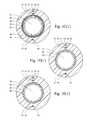
- FIG. 1 ais a tear-away side view of an access sheath in accordance with an embodiment of the present invention
- FIG. 1 bis tear-away side view of an access sheath in accordance with another embodiment of the present invention.
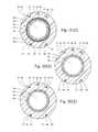
- FIG. 1 c 1is one example of a cross-section of the access sheath depicted in FIG. 1 a;
- FIG. 1 c 2is another example of a cross-section of the access sheath depicted in FIG. 1 a;
- FIG. 1 d 1is one example of a cross-section of the access sheath depicted in FIG. 1 a;
- FIG. 1 d 2is another example of a cross-section of the access sheath depicted in FIG. 1 a;
- FIG. 1 e 1is one example of a cross-section of the access sheath depicted in FIG. 1 a;
- FIG. 1 e 2is another example of a cross-section of the access sheath depicted in FIG. 1 a;
- FIG. 2 ais an environmental view of an access sheath in accordance with an embodiment of the present invention.
- FIG. 2 bis an environmental view of an access sheath in accordance with one embodiment of the present invention.
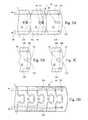
- FIG. 3 ais a side view of a portion of an access sheath in accordance with an embodiment of the present invention.
- FIG. 3 bis a side view of a portion of an access sheath in accordance with one embodiment of the present invention.
- FIG. 3 cis a side view of a portion of an access sheath in accordance with another embodiment of the present invention.
- FIG. 3 dis a side view of a portion of an access sheath in accordance with one embodiment of the present invention.
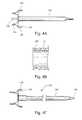
- FIG. 4 ais a side view of an insert for use with an access sheath in accordance with an embodiment of the present invention
- FIG. 4 bis a partial cross-sectional view of a proximal portion of an access sheath for interfacing with the insert depicted in FIG. 4 a in accordance with one embodiment of the present invention
- FIG. 4 cis an obturator for use with an access sheath in accordance with another embodiment in the present invention.
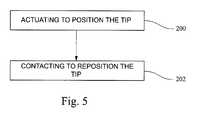
- FIG. 5is an example of a method for positioning an access sheath in a patient's body in accordance with the present invention.
- Examples of the present inventionseek to overcome some of the concerns associated with accessing body pathways and cavities, which may be tortuous, during endoscopic and laparoscopic surgery.
- Embodiments of the present inventionconcern a steerable access sheath that may be used for endoscopic or laparoscopic surgical procedures.
- An endoscopeespecially a flexible endoscope, is an optical instrument that transmits light and carries images back to an observer through a flexible bundle of small (about 10 micrometers) transparent fibers.
- Such an endoscopeis used to inspect interior portions of the body, may be equipped with mechanisms for steering, and may have additional lumens for allowing sampling and/or operative instruments along their axis to the internal site.
- an endoscopeis first and foremost a medical device for diagnostic procedures, and is defined as an optical instrument.
- the instrumentmay or may not have a steering mechanism and it may or may not have an additional lumen, i.e., a working channel, for sampling or operating instruments.
- Endoscopesare typically narrow, with an outer diameter from about 3.0 to 6.0 millimeters (mm).
- the “working channel”may be from about 0.8 to 1.2 mm in diameter (about 2.4 French (Fr.) to 3.6 Fr.).
- An access sheathis not primarily an optical instrument and may or may not use an optical system.
- the access sheathcomprises an elongated member having two deflection sections for positioning and repositioning its distal tip.
- the access sheathalso includes a stiffening section that includes at least two concentrically positioned reinforcement layers about a working lumen which enhance stiffness and concentrate bending forces at the deflection sections.
- the stiffening sectionfacilitates bending of the deflection sections to position and/or reposition the tip for preferably maneuvering through even tortuous body passageways and cavities during endoscopic and laparoscopic surgery.
- an access sheath 10 for positioning in a patient in accordance with at least one embodiment of the present inventionis provided.
- the access sheath 10comprises an elongated member 12 that has a proximal portion 14 extending to a distal portion 16 .
- Defined by the access sheath 10are several lumens including a large or working lumen 18 and a plurality of smaller additional lumens 20 , 22 and 24 as illustrated in FIGS. 1 c 1 , 1 d 1 and 1 e 1 , or 20 , 22 , 22 ′, 24 and 24 ′ as illustrated in FIGS. 1 c 2 , 1 d 2 and 1 e 2 for example.
- the working lumen 18is lined with a layer of lubricious polymer 26 , such as a fluoropolymer liner, e.g., polytetrafluoroethylene (PTFE) or Teflon®.
- a fluoropolymer linere.g., polytetrafluoroethylene (PTFE) or Teflon®.
- the additional lumens 20 , 22 and 24are lined with a fluoropolymer liner 27 or other lubricious material on its inner surface.
- Polyethylene, polypropylene or other polymermay be used instead of a fluoropolymer.
- the working lumen 18is desirably larger than the additional lumens 20 , 22 and 24 and may be used for therapeutic or diagnostic purposes, such as removing kidney or bile stones, or for collecting a biopsy sample.
- the first additional lumen 20may be used to receive an optical system 28 which is for guiding the interventionalist (e.g. physician or other medical professional) during a therapeutic procedure.
- the optical system 28may be connected by a connector 30 on the proximal portion 14 of the access sheath 10 .
- the optical system 28preferably includes a lens and an optical fiber for transmitting light to the lens so that an image is transmitted from the lens to the interventionalist.
- An eyepiece and a light sourceare also desirable components but may or may not be part of the removable optical assembly 28 .
- Components for an optical system 28may be purchased, for example, from Fujikura America, Atlanta, Ga. These include image fibers, light sources and light guides, fiber scopes with image fibers, digital optics (e.g. including CMOS and CCD), eyepieces, and lens. These components are relatively very thin, useful, and inexpensive. Other suitable optical systems known to those skilled in the art may alternatively be used.
- the access sheath 10is desirably sufficiently inexpensive for one time only use.
- the proximal portion 14 of the elongated member 12has a stiffening section 32 .
- the stiffening section 32comprises at least two reinforcement layers including a first reinforcement layer 34 and a second reinforcement layer 36 .
- the reinforcement layers 34 and 36are disposed about the working lumen 18 and are in concentric relationship with each other.
- the first reinforcement layer 34is formed of a coil wrapping 35 comprising a plurality of flat wire turns 37 which, for example, are positioned at an acute angle to the working lumen 18 and are uniformly spaced apart in the range of about 0.005 inches to 0.015 inches between the turns.
- the coil wrapping 35may be formed, for example, from 0.003 inch thick by 0.012 inch wide flat stainless steel wire. The coil wrapping 35 is compression fitted around the outer surface of the inner liner 26 of the working lumen 18 .
- the second reinforcement layer 36is formed from a braiding 48 that is compression fitted to and wrapped around the first reinforcement layer 34 .
- the braiding 48may be, for example, constructed of stainless steel wire arranged in warp and weft directions 50 and 52 to form a bi-directional woven pattern. It is believed that the bi-direction pattern of the braiding 48 enhances stiffness of the stiffening section 32 by providing bi-directional stress distribution.
- the second reinforcement layer 36is formed from a second coil wrapping 54 that is compression fitted to and wrapped around the first coil wrapping 35 .
- the second coil wrapping 54may be constructed similar to the first coil wrapping 35 but with its flat wire turns 55 positioned at an angle to the flat wire turns 37 of the first coil wrapping 35 to provide bi-directional stress distribution for enhancing stiffness of the stiffening section 32 .
- a polymeric layer or liner 58is disposed about the second reinforcement layer 36 and forms an exterior layer of the stiffening section 32 .
- the exterior liner 58may be made from a polymeric material, such as silicone, nylon or urethane.
- Other medically acceptable thermoplastic or thermoset materialmay also be used either separately or in combination, including PTFE, a fluoropolymer, polyethylene, polypropylene, acetyl, urethane, and others.
- the access sheath 10has a tip 38 .
- the working lumen 18is formed through the tip 38 for providing access to a patient's body when the distal portion 16 of the sheath 10 is positioned in the patient.
- the distal portion 16also has at least two deflection sections including a first deflection section 40 and a second deflection section 42 .
- the deflection sections 40 and 42bend relative to the stiffening section 32 to position and reposition the tip 38 in the patient's body.
- the first deflection section 40is proximal to the tip 38 and is distal to the second deflection section 42 .
- the first deflection section 40includes a coil wrapping 60 , which may be a continuation of the coil wrapping 35 from the stiffening section 32 or it may be a separate coil wrapping (e.g. similarly constructed or otherwise).
- the coil wrapping 60is disposed about the working lumen 18 and is preferably compression fitted around the inner liner 26 .
- Forming an exterior layer of the first deflection section 40is a polymeric liner 62 .
- the liner 62is disposed about the coil wrapping 60 and is made of a polymeric material having a lower durometer than the durometer of the outer liner 58 of the stiffening section 32 to facilitate bending of the deflection section 40 .
- the liner 62 of the first deflection section 40has a Shore D durometer of between about 10 to 50 (preferably between about 25 and 40), and the liner 58 of the stiffening section 32 has a Shore D durometer of between about 50 and 90 (preferably between about 55 and 72).
- thermoplastics and/or thermosetsmay be used to make the liner 62 , such as for example, silicone, nylon, urethane, PTFE, a fluoropolymer, polyethylene, polypropylene, acetyl, urethane, and others.
- the first deflection section 40is configured to be “actively deflected” by an interventionalist.
- the access sheath 10comprises at least one control wire 46 moveably disposed in at least one of the additional lumens 22 , 22 ′, 24 and/or 24 ′ for actively bending the first deflection section 40 .
- the control wire 46is connected at its distal end to the distal portion 16 of the elongated member 12 so that the tip 38 may be easily bent at an angle and maneuvered by the interventionalist.
- the additional lumens 22 , 22 ′, 24 and/or 24 ′do not extend through the tip 38 , but rather terminate between the first deflection section 40 and the tip 38 .
- the distal end of the control wire 46is anchored within the distal portion 16 via an anchor or cannula 64 disposed in the additional lumens 22 , 22 ′, 24 and/or 24 ′, so that when tension is applied to the control wire 46 , the control wire 46 will cause the first deflection section 40 to bend at an angle to position the tip 38 .
- the proximal end of the control wire 46may be joined to a control handle 66 , such as for example, a integral thumb actuator as shown or a separate handle or otherwise, for manipulation of the control wire 46 .
- the control wire 46may be a single steel wire, or may be a wire bundle.
- the control wire 46may use filaments made from other materials, such as nylons, polyesters, or other polymers, or polymer reinforced with glass, carbon, or metallic wires or fibers.
- the control handle 66has easy-to-use controls so that the interventionalist can readily adjust the position of the tip 38 via the first deflection section 40 .
- a retainer 68is preferably molded into the proximal portion 14 of the elongated member 12 , or otherwise assembled in place.
- the retainer 68has a base portion 70 and a curved rack of teeth 72 .
- the base portion 70also has a pivot point or pin 74 .
- One aperture 76is for access for the control wire 46 for assembly with the actuator 78 .
- the actuator 78includes a proximal portion 80 for interfacing with the hand or thumb of the interventionalist, and a distal portion 81 which mounts on the pivot pin 74 .
- a spring(not shown) is operably disposed in the actuator 78 to allow the interventionalist to depress the proximal portion 80 and disengage a locking member 83 , for example, from engagement with the rack of teeth 72 to allow pivoting of the actuator 78 on the pivot pin 74 to move the position of the actuator 78 on the rack of teeth 72 , thereby moving the control wire 46 to bend the first deflection section 40 .
- the proximal portion 80can then be released by the interventionalist so that the spring moves the locking member 83 outwardly back into engagement with the curved rack of teeth 72 to lock the first deflection section 40 at a specific deflection position.
- Other suitable control handle arrangementsmay also be employed such as those disclosed in U.S. Patent Application Publication 2007/0203474 which is incorporated herein by reference in its entirety.
- the access sheath 10may include one or more control wires 46 , preferably distributed radially across the proximal and distal portions 14 and 16 of the elongated member 12 .
- the control wires 46may be connected at radial intervals of 180°, 120°, or 90° if there are, respectively two, three, or four control wires 46 .
- two pairs of control wires 46may be positioned such that each pair is on opposing sides of the access sheath 10 relative to the other pair, and each control wire 46 of a corresponding pair is spaced apart and adjacent to the other control wire 46 of the corresponding pair.
- the first deflection section 40is preferably sufficiently flexible to bend in response to actuation of the control handle 66 to an angle of at least 90° to position the tip 38 .
- the first deflection section 40may be bent around and at angle of at least 180° or more, such as for example 225°-270° to position the tip 38 .
- the second deflection section 42is configured to bend at a second angle to reposition the tip 38 .
- the second deflection section 42uses “passive deflection” to bend at the second angle. That is, the second deflection section 42 bends in response to being contacted or bumped by an external object, such as for example, part of the patient's body.
- active deflectionmay be used to bend the second deflection section 42 .
- the second deflection section 42includes a series articulating members 82 that are disposed about the working lumen 18 and around the inner liner 26 .
- the articulating members 82are pivotally connected to each other to bend the second deflection section 42 to the second angle.
- the articulating members 82are formed from a laser cut cannula 84 .
- Each of the articulating members 82has a positive feature 86 and a negative feature 88 .
- the positive feature 86 of one articulating member 82engages the negative feature 88 of the adjacent articulating member 82 to form a pivotal connection 90 .
- the polymeric liner 92is made of a polymeric material having a lower durometer than the durometer of the outer liner 58 of the stiffening section 32 to facilitate bending of the second deflection section 42 .
- the polymeric liner 92is made of the same or similar polymeric material as the polymeric liner 62 of the first deflection section 40 .
- the second deflection 42 sectionsmay be disposed immediately adjacent to the first deflection section 40 .
- the second deflection section 42may be spaced apart from the first deflection section 40 .
- an additional stiffening section 94is disposed between the first and second deflection sections 40 and 42 for providing a particular positioning and reposition pattern (e.g. with pivotal reach) for the tip 38 that may well suited for navigating certain tortuous passageways.
- the additional stiffening section 94preferable has the same or similar layer construction as the stiffening section 32 of the sheath's proximal portion 14 with either a coil-on-coil or a coil-on-braiding or vice versa reinforcement layer construction as described in detail in the foregoing paragraphs.
- the articulating members 82each have a pin 96 and a slot 98 .
- the pin 96 of one of the articulating members 82engages the slot 98 of the adjacent articulating number 82 to form the pivotal connection 90 .
- the articulating members 82move axially 100 relative to each other from a relaxed position 102 to a compressed position 104 when a first deflection section 40 is actuated to bend.
- the axial movement 100 of the articulating members 82 to the compressed position 104does not cause the second deflection section 42 to bend or substantially bend, but rather restrains pivotal movement of the articulating members 82 , which is believed to concentrate or enhance the forces for bending the first deflection section 40 .
- the slots 98may be configured to facilitate pivotal movement in the relaxed position 102 and to restrain pivotal movement in the compressed position 104 .
- the slots 98may each have a relatively narrow proximal portion 99 , which more tightly engages the pin 96 to restrain pivotal movement in the compressed position 104 , and a relatively wider distal portion 101 , which allows the pin 96 more freedom to move therein to facilitate pivotal movement in the relaxed position 102 .
- the proximal portion 99may be configured as a narrow straight slot
- the distal portion 101may be configured as a relatively wider circular opening extending from the proximal portion 99 as illustrated in FIG. 3 a .
- the slots 98may be configured as “T” or triangular openings as illustrated in FIGS. 3 b and 3 c , respectively.
- At least one additional control wire 106is provided for facilitating axial movement 100 of the articulating members 82 to the compressed position 104 .
- Each additional control wire 106is preferably movably disposed in one of the additional lumens.
- the additional control wire 106has one end 108 connected to one of the articulating members 82 positioned distally in the series of articulating members 82 and the other end 110 operably connected to a second retainer-actuator arrangement 112 of the control handle 66 for moving the articulating members 82 proximally to the compressed position 104 .
- the second retainer-actuator arrangement 112operates the same as or similar to the retainer-actuator arrangement 68 , 70 , 72 , 74 , 76 and 78 as discussed previously.
- the additional control wire 106may also include a spring 114 disposed between the two ends 108 and 110 to facilitate the articulating members 82 moving distally from the compressed position 104 to pivot when a portion of elongated member 12 contacts an external object.
- an insert 120 for use with the access sheath 10is provided.
- the insert 120is meant to clip onto the proximal portion 14 of the access sheath 10 using the interface 122 and a mating proximal portion 123 of the access sheath 10 as shown in FIG. 4 b .
- the interface 122is operated by a finger lever 124 , the interventionalist squeezing the levers 124 to part the interface portions 122 in order to apply the interface 122 to the access sheath 10 .
- the interventionalistthen releases the levers 124 , allowing the interface portions 122 and notches 126 to latch the mating proximal portion 123 of the access sheath 10 .
- the interface 122may include control portion 128 and may also include diagnostic or a therapeutic device 130 , such as a retriever for kidney stones or a laser fiber for breaking up calculi in a kidney or other organ.
- the control portion 128may be a control rod, or other connection for the desired diagnostic or therapeutic device 130 .
- the control portion 128is used to manipulate the device 140 , e.g., extending and retracting a retrieval basket for removing kidney stones.
- an obturator 132is useful in deploying the access sheath 10 into a patient.
- the obturator 132occupies the working lumen 18 of the sheath 10 , preventing its collapse during deployment. Alternatively, the obturator 132 may be used after deployment in order to expand the working lumen 18 .
- the obturator 18extends from the proximal portion 14 to the distal portion 16 of the access sheath 10 .
- the obturator 132includes a main shaft 134 , a distal tip 136 , and a proximal portion 138 .
- the distal tip 136may be tapered as shown for easy introduction.
- the proximal portion 138preferably includes an engaging portion or connector 140 for removeably clipping or attaching to the mating portion 123 of the proximal portion 14 of the access sheath 10 .
- an example of a method for positioning an access sheath in a patient's body by an interventionalistis provided.
- the access sheath 10is advanced through the ureter 150 to access the kidney 152 of the patent for kidney stone 154 removal.
- the first deflection section 40is actuated (at 200 ) to bend at a first angle to position the tip 38 adjacent to the lower, outboard calyx 156 .
- the distal portion 16 of the access sheath 10is contacted with or bumped against (at 202 ) the kidney 152 to produce a force that bends the second deflection section 42 at a second angle, repositioning the tip 38 (e.g. with pivotal reach) into the lower, inboard calyx 158 where, in this example, the kidney stone 154 is located.
- a retrieval device 160is deployed out the working lumen to remove the kidney stone 154 .
Landscapes
- Health & Medical Sciences (AREA)
- Life Sciences & Earth Sciences (AREA)
- Surgery (AREA)
- Engineering & Computer Science (AREA)
- Veterinary Medicine (AREA)
- Public Health (AREA)
- Biomedical Technology (AREA)
- Heart & Thoracic Surgery (AREA)
- Animal Behavior & Ethology (AREA)
- General Health & Medical Sciences (AREA)
- Biophysics (AREA)
- Pathology (AREA)
- Nuclear Medicine, Radiotherapy & Molecular Imaging (AREA)
- Medical Informatics (AREA)
- Molecular Biology (AREA)
- Physics & Mathematics (AREA)
- Optics & Photonics (AREA)
- Radiology & Medical Imaging (AREA)
- Pulmonology (AREA)
- Anesthesiology (AREA)
- Hematology (AREA)
- Mechanical Engineering (AREA)
- Media Introduction/Drainage Providing Device (AREA)
- Endoscopes (AREA)
Abstract
Description
Claims (9)
Priority Applications (1)
| Application Number | Priority Date | Filing Date | Title |
|---|---|---|---|
| US13/319,850US8758231B2 (en) | 2009-05-14 | 2010-05-12 | Access sheath with active deflection |
Applications Claiming Priority (3)
| Application Number | Priority Date | Filing Date | Title |
|---|---|---|---|
| US17818909P | 2009-05-14 | 2009-05-14 | |
| PCT/US2010/034536WO2010132560A1 (en) | 2009-05-14 | 2010-05-12 | Access sheath with active deflection |
| US13/319,850US8758231B2 (en) | 2009-05-14 | 2010-05-12 | Access sheath with active deflection |
Publications (2)
| Publication Number | Publication Date |
|---|---|
| US20120053415A1 US20120053415A1 (en) | 2012-03-01 |
| US8758231B2true US8758231B2 (en) | 2014-06-24 |
Family
ID=42941931
Family Applications (1)
| Application Number | Title | Priority Date | Filing Date |
|---|---|---|---|
| US13/319,850Active2030-09-06US8758231B2 (en) | 2009-05-14 | 2010-05-12 | Access sheath with active deflection |
Country Status (3)
| Country | Link |
|---|---|
| US (1) | US8758231B2 (en) |
| EP (1) | EP2429427B1 (en) |
| WO (1) | WO2010132560A1 (en) |
Cited By (31)
| Publication number | Priority date | Publication date | Assignee | Title |
|---|---|---|---|---|
| USD735327S1 (en)* | 2013-07-29 | 2015-07-28 | Cook Medical Technologies Llc | Transitional handle |
| US9314593B2 (en) | 2012-09-24 | 2016-04-19 | Cook Medical Technologies Llc | Medical devices for the identification and treatment of bodily passages |
| US9549748B2 (en) | 2013-08-01 | 2017-01-24 | Cook Medical Technologies Llc | Methods of locating and treating tissue in a wall defining a bodily passage |
| US9833130B2 (en) | 2011-07-22 | 2017-12-05 | Cook Medical Technologies Llc | Irrigation devices adapted to be used with a light source for the identification and treatment of bodily passages |
| US9895055B2 (en) | 2013-02-28 | 2018-02-20 | Cook Medical Technologies Llc | Medical devices, systems, and methods for the visualization and treatment of bodily passages |
| US20180055589A1 (en)* | 2016-08-26 | 2018-03-01 | Hansen Medical, Inc. | Steerable catheter with shaft load distributions |
| US9937323B2 (en) | 2014-02-28 | 2018-04-10 | Cook Medical Technologies Llc | Deflectable catheters, systems, and methods for the visualization and treatment of bodily passages |
| US10195398B2 (en) | 2014-08-13 | 2019-02-05 | Cook Medical Technologies Llc | Tension member seal and securing mechanism for medical devices |
| US10405939B2 (en) | 2013-10-24 | 2019-09-10 | Auris Health, Inc. | Endoscopic device with helical lumen design |
| US10493241B2 (en) | 2014-07-01 | 2019-12-03 | Auris Health, Inc. | Apparatuses and methods for monitoring tendons of steerable catheters |
| US10525231B2 (en) | 2016-01-01 | 2020-01-07 | Tractus Vascular, Llc | Flexible catheter |
| US10555780B2 (en) | 2010-09-17 | 2020-02-11 | Auris Health, Inc. | Systems and methods for positioning an elongate member inside a body |
| US10667720B2 (en) | 2011-07-29 | 2020-06-02 | Auris Health, Inc. | Apparatus and methods for fiber integration and registration |
| US20200205908A1 (en)* | 2018-12-28 | 2020-07-02 | Auris Health, Inc. | Medical instrument with articulable segment |
| US10716461B2 (en) | 2017-05-17 | 2020-07-21 | Auris Health, Inc. | Exchangeable working channel |
| US10792464B2 (en) | 2014-07-01 | 2020-10-06 | Auris Health, Inc. | Tool and method for using surgical endoscope with spiral lumens |
| US10894145B2 (en) | 2017-09-22 | 2021-01-19 | Cook Medical Technologies Llc | Steerable catheter system with hub |
| US10898276B2 (en) | 2018-08-07 | 2021-01-26 | Auris Health, Inc. | Combining strain-based shape sensing with catheter control |
| US11109920B2 (en) | 2018-03-28 | 2021-09-07 | Auris Health, Inc. | Medical instruments with variable bending stiffness profiles |
| US11135398B2 (en) | 2018-07-19 | 2021-10-05 | Neptune Medical Inc. | Dynamically rigidizing composite medical structures |
| US20210338984A1 (en)* | 2020-05-01 | 2021-11-04 | Robert Booker | Deflectable catheter systems and methods of use |
| US11179212B2 (en) | 2018-09-26 | 2021-11-23 | Auris Health, Inc. | Articulating medical instruments |
| US11285294B2 (en) | 2018-08-17 | 2022-03-29 | Cook Medical Technologies Llc | Introducer with sheath having a withdrawal support wire |
| US11350998B2 (en) | 2014-07-01 | 2022-06-07 | Auris Health, Inc. | Medical instrument having translatable spool |
| US11413428B2 (en) | 2013-03-15 | 2022-08-16 | Auris Health, Inc. | Catheter insertion system and method of fabrication |
| US11464586B2 (en) | 2009-04-29 | 2022-10-11 | Auris Health, Inc. | Flexible and steerable elongate instruments with shape control and support elements |
| US11617627B2 (en) | 2019-03-29 | 2023-04-04 | Auris Health, Inc. | Systems and methods for optical strain sensing in medical instruments |
| US11717147B2 (en) | 2019-08-15 | 2023-08-08 | Auris Health, Inc. | Medical device having multiple bending sections |
| US11723636B2 (en) | 2013-03-08 | 2023-08-15 | Auris Health, Inc. | Method, apparatus, and system for facilitating bending of an instrument in a surgical or medical robotic environment |
| US11819636B2 (en) | 2015-03-30 | 2023-11-21 | Auris Health, Inc. | Endoscope pull wire electrical circuit |
| US11950872B2 (en) | 2019-12-31 | 2024-04-09 | Auris Health, Inc. | Dynamic pulley system |
Families Citing this family (14)
| Publication number | Priority date | Publication date | Assignee | Title |
|---|---|---|---|---|
| US20140046137A1 (en)* | 2012-08-08 | 2014-02-13 | Ronda Duke Brown | Retractor Cover Apparatus and Associated Methods |
| JP6201368B2 (en)* | 2013-03-27 | 2017-09-27 | 住友ベークライト株式会社 | Medical equipment |
| WO2014156352A1 (en)* | 2013-03-28 | 2014-10-02 | オリンパス株式会社 | Outer sleeve tube and treatment tool |
| EP3318205B1 (en)* | 2015-07-01 | 2020-01-29 | Olympus Corporation | Treatment instrument for endoscope |
| US10799224B2 (en) | 2016-03-30 | 2020-10-13 | Ihsan Tasci | Device for laparoscopic surgery |
| DE202018104602U1 (en)* | 2018-08-10 | 2018-08-17 | Lohmann & Rauscher Gmbh | protective sleeve |
| US20210386441A1 (en)* | 2018-11-07 | 2021-12-16 | Richard Wolf Gmbh | Endoscopic instrument |
| EP3934507A4 (en)* | 2019-03-04 | 2022-11-09 | Georgia Tech Research Corporation | STEERING AND FLEXIBLE ROBOTIC ENDOSCOPIC TOOLS FOR MINIMALLY INVASIVE PROCEDURES |
| CN209952029U (en)* | 2019-04-03 | 2020-01-17 | 广西医师协会 | Direction-changeable ureter soft lens guiding sheath |
| US20210220605A1 (en)* | 2020-01-21 | 2021-07-22 | Becton, Dickinson And Company | Tubular instrument and related devices and methods |
| USD942621S1 (en) | 2020-04-02 | 2022-02-01 | The First Affiliated Hospital Of Guangxi Medical University | Bendable ureteral access sheath |
| US11344188B1 (en)* | 2021-05-30 | 2022-05-31 | OTU Medical Inc. | Actively bendable sheath for delivering medical instrument therethrough and method thereof |
| CN115054805B (en)* | 2022-07-05 | 2025-07-25 | 深圳市库珀科技发展有限公司 | Bendable guiding sheath tube and guiding device |
| US20250127385A1 (en)* | 2023-10-20 | 2025-04-24 | Boston Scientific Scimed, Inc. | Medical device shafts and related methods of manufacture |
Citations (84)
| Publication number | Priority date | Publication date | Assignee | Title |
|---|---|---|---|---|
| US4838339A (en)* | 1987-08-26 | 1989-06-13 | K. W. Thompson Tool Company, Inc. | Mold for hollow point bullet |
| WO1991001772A1 (en) | 1989-07-31 | 1991-02-21 | Radi Medical Systems Ab | Catheter, manipulator and combination thereof |
| US4997424A (en) | 1989-04-05 | 1991-03-05 | Medamicus, Inc. | Catheter introducer and introducer slitter |
| US5188606A (en) | 1991-09-11 | 1993-02-23 | Medamicus, Inc. | Multiple size introducer slitter |
| USRE34502E (en) | 1988-11-18 | 1994-01-11 | Webster, Jr.; Wilton W. | Steerable catheter |
| US5304142A (en) | 1992-08-04 | 1994-04-19 | Medamicus, Inc. | Dilator - Introducer locking hub and sheath valve apparatus |
| US5380304A (en) | 1991-08-07 | 1995-01-10 | Cook Incorporated | Flexible, kink-resistant, introducer sheath and method of manufacture |
| US5429616A (en) | 1994-05-31 | 1995-07-04 | Schaffer; David I. | Occludable catheter |
| US5431168A (en) | 1993-08-23 | 1995-07-11 | Cordis-Webster, Inc. | Steerable open-lumen catheter |
| US5599305A (en) | 1994-10-24 | 1997-02-04 | Cardiovascular Concepts, Inc. | Large-diameter introducer sheath having hemostasis valve and removable steering mechanism |
| US5704898A (en) | 1995-11-17 | 1998-01-06 | Circon Corporation | Articulation mechanism for an endoscope |
| EP0815895A1 (en) | 1996-06-03 | 1998-01-07 | Terumo Kabushiki Kaisha | Tubular medical device |
| US5755760A (en) | 1996-03-11 | 1998-05-26 | Medtronic, Inc. | Deflectable catheter |
| US5772578A (en) | 1995-09-14 | 1998-06-30 | Richard Wolf Gmbh | Endoscopic instrument |
| US5865800A (en) | 1993-08-19 | 1999-02-02 | Boston Scientific Corporation | Deflectable catheter |
| US5897529A (en) | 1997-09-05 | 1999-04-27 | Cordis Webster, Inc. | Steerable deflectable catheter having improved flexibility |
| US6064905A (en) | 1998-06-18 | 2000-05-16 | Cordis Webster, Inc. | Multi-element tip electrode mapping catheter |
| US6066126A (en) | 1997-12-18 | 2000-05-23 | Medtronic, Inc. | Precurved, dual curve cardiac introducer sheath |
| US6066125A (en) | 1997-09-05 | 2000-05-23 | Cordis Webster, Inc. | Omni-directional steerable catheter |
| US6102887A (en) | 1998-08-11 | 2000-08-15 | Biocardia, Inc. | Catheter drug delivery system and method for use |
| US6183463B1 (en) | 1997-12-01 | 2001-02-06 | Cordis Webster, Inc. | Bidirectional steerable cathether with bidirectional control handle |
| US6198974B1 (en) | 1998-08-14 | 2001-03-06 | Cordis Webster, Inc. | Bi-directional steerable catheter |
| US6203507B1 (en) | 1999-03-03 | 2001-03-20 | Cordis Webster, Inc. | Deflectable catheter with ergonomic handle |
| US6210362B1 (en) | 1997-09-05 | 2001-04-03 | Cordis Webster, Inc. | Steerable catheter for detecting and revascularing ischemic myocardial tissue |
| US6210407B1 (en) | 1998-12-03 | 2001-04-03 | Cordis Webster, Inc. | Bi-directional electrode catheter |
| US6240231B1 (en) | 1997-12-22 | 2001-05-29 | Micrus Corporation | Variable stiffness fiber optic shaft |
| US6277108B1 (en) | 1999-06-04 | 2001-08-21 | Medamicus, Inc. | Introducer with location marker |
| US20010034514A1 (en) | 2000-03-23 | 2001-10-25 | Cook Incorporated | Introducer sheath |
| US20010037084A1 (en) | 2000-04-28 | 2001-11-01 | Mahase Nardeo | Steerable medical catheter with bendable encapsulated metal spring tip fused to polymeric shaft |
| US6319244B2 (en) | 1999-03-16 | 2001-11-20 | Chase Medical, L.P. | Catheter with flexible and rigid reinforcements |
| WO2002011807A2 (en) | 2000-08-08 | 2002-02-14 | Boston Scientific Limited | Controlled depth injection device and method |
| US6352531B1 (en) | 1999-03-24 | 2002-03-05 | Micrus Corporation | Variable stiffness optical fiber shaft |
| US6419641B1 (en) | 2000-11-28 | 2002-07-16 | Promex, Llc | Flexible tip medical instrument |
| US6458076B1 (en) | 2000-02-01 | 2002-10-01 | 5 Star Medical | Multi-lumen medical device |
| US6471648B1 (en) | 2000-07-17 | 2002-10-29 | Acuson Corporation | Medical diagnostic ultrasound imaging system with a rotatable user interface element having a non-rotatable indicator |
| US20020161353A1 (en) | 2001-04-30 | 2002-10-31 | Bart-Jan Kortelling | Steerable catheter with reinforced tip |
| US6475184B1 (en) | 2000-06-14 | 2002-11-05 | Scimed Life Systems, Inc. | Catheter shaft |
| US20030004460A1 (en) | 2000-01-06 | 2003-01-02 | Bedell Raymond L | Steerable fiberoptic epidural balloon catheter and scope |
| US6503193B1 (en)* | 1999-04-14 | 2003-01-07 | Pentax Corporation | Flexible tube for endoscope |
| US6537480B1 (en) | 1998-09-11 | 2003-03-25 | Advanced Cardiovascular Systems, Inc. | Method of manufacturing a catheter with a flexible tip and taper |
| US6551302B1 (en) | 1997-09-24 | 2003-04-22 | Michael J. Rosinko | Steerable catheter with tip alignment and surface contact detector |
| US6554794B1 (en) | 1997-09-24 | 2003-04-29 | Richard L. Mueller | Non-deforming deflectable multi-lumen catheter |
| US6571131B1 (en) | 2000-11-10 | 2003-05-27 | Biosense Webster, Inc. | Deflectable catheter with modifiable handle |
| US20030135156A1 (en) | 1998-10-02 | 2003-07-17 | Bencini Robert F. | Steerable device for introducing diagnostic and therapeutic apparatus into the body |
| US20030135198A1 (en) | 1999-07-23 | 2003-07-17 | Tfx Medical Extrusion Products | Catheter device having multi-lumen reinforced shaft and method of manufacture for same |
| US6638213B2 (en)* | 2000-10-02 | 2003-10-28 | Olympus Optical Co., Ltd. | Endoscope |
| US6641564B1 (en) | 2000-11-06 | 2003-11-04 | Medamicus, Inc. | Safety introducer apparatus and method therefor |
| WO2003090835A1 (en) | 2002-04-25 | 2003-11-06 | Medtronic, Inc. | Improved system and method for positioning implantable medical devices within coronary veins |
| US20030236493A1 (en) | 2002-06-25 | 2003-12-25 | Medamicus, Inc. | Articulating handle for a deflectable catheter and method therefor |
| US20040015138A1 (en) | 2002-07-16 | 2004-01-22 | Clifford Currier | Multiple lumen catheter having a soft tip |
| US20040044350A1 (en) | 1999-04-09 | 2004-03-04 | Evalve, Inc. | Steerable access sheath and methods of use |
| US20040054377A1 (en) | 2002-07-12 | 2004-03-18 | Foster Thomas L. | Flexible cannula |
| US6712789B1 (en) | 2000-07-13 | 2004-03-30 | Medamicus, Inc. | Introducer having a movable valve assembly with removable side port |
| US6716223B2 (en) | 2001-11-09 | 2004-04-06 | Micrus Corporation | Reloadable sheath for catheter system for deploying vasoocclusive devices |
| US6723070B1 (en) | 1998-06-02 | 2004-04-20 | K. K. Vayu | Balloon catheter |
| US20040092962A1 (en) | 1999-04-09 | 2004-05-13 | Evalve, Inc., A Delaware Corporation | Multi-catheter steerable guiding system and methods of use |
| US6796976B1 (en) | 1998-03-06 | 2004-09-28 | Scimed Life Systems, Inc. | Establishing access to the body |
| US20040193112A1 (en) | 2003-03-26 | 2004-09-30 | Medamicus, Inc. | Safety introducer assembly and method |
| US20040220549A1 (en) | 2003-04-14 | 2004-11-04 | Dittman Jay A. | Large diameter delivery catheter/sheath |
| WO2004096015A2 (en) | 2003-04-25 | 2004-11-11 | Applied Medical Resources Corporation | Steerable kink-resistant sheath |
| US20040236346A1 (en) | 2003-04-25 | 2004-11-25 | Cook Incorporated | Delivery catheter and method of manufacture |
| US20040242966A1 (en) | 2003-06-02 | 2004-12-02 | Barry James P. | Wire spring guide for flexible endoscope |
| US20050004515A1 (en) | 2002-11-15 | 2005-01-06 | Hart Charles C. | Steerable kink resistant sheath |
| US6855106B2 (en) | 2000-03-16 | 2005-02-15 | Medivision, Inc. | Endoscope and camera mount |
| US20050043712A1 (en)* | 2003-08-21 | 2005-02-24 | Devens Douglas A. | Multilayer medical devices |
| US20050065467A1 (en) | 2003-09-24 | 2005-03-24 | Greg Pudelko | Bi-directional catheter assembly and method therefor |
| US20050065474A1 (en) | 2000-08-08 | 2005-03-24 | Scimed Life Systems, Inc. | Catheter assembly |
| US20050165366A1 (en) | 2004-01-28 | 2005-07-28 | Brustad John R. | Medical tubing having variable characteristics and method of making same |
| US20050192606A1 (en) | 2004-02-27 | 2005-09-01 | Paul Ram H.Jr. | Valvulotome with a cutting edge |
| US6951555B1 (en) | 1998-03-16 | 2005-10-04 | Chase Medical, L.P. | Catheter having integral expandable/collapsible lumen |
| US20050222664A1 (en) | 2004-04-06 | 2005-10-06 | Parker Fred T | Prosthesis deployment system |
| US20050222581A1 (en) | 2004-03-30 | 2005-10-06 | Vance Products Incorporated, D/B/A | Multiple lumen access sheath |
| US20050228479A1 (en) | 2001-11-29 | 2005-10-13 | Cook Incorporated | Medical device delivery system |
| US20050256452A1 (en) | 2002-11-15 | 2005-11-17 | Demarchi Thomas | Steerable vascular sheath |
| WO2005123169A1 (en) | 2004-06-14 | 2005-12-29 | Applied Medical Resources Corporation | Steerable vascular sheath |
| US20060178560A1 (en)* | 2003-01-15 | 2006-08-10 | Usgi Medical, Inc. | Endoluminal tool deployment system |
| US20060200000A1 (en) | 2004-09-03 | 2006-09-07 | Olympus Corporation | Endoscope |
| US7122020B2 (en) | 2004-06-25 | 2006-10-17 | Mogul Enterprises, Inc. | Linkage steering mechanism for deflectable catheters |
| WO2006110275A2 (en) | 2005-04-11 | 2006-10-19 | Usgi Medical Inc. | Methods and apparatus for off-axis visualization |
| US7135015B2 (en) | 1999-04-30 | 2006-11-14 | Applied Medical Resources Corporation | Ureteral access sheath |
| US20070066869A1 (en)* | 2005-09-21 | 2007-03-22 | David Hoffman | Endoscopic assembly including cap and sheath |
| US20070078455A1 (en) | 1997-06-20 | 2007-04-05 | Rassoll Rashidi | Electrophysiology/ablation catheter and remote actuator therefor |
| US20070203474A1 (en) | 2006-01-09 | 2007-08-30 | Vance Products Incorporated | Deflectable tip access sheath |
| US8366607B2 (en)* | 2004-09-30 | 2013-02-05 | Boston Scientific Scimed, Inc. | Manually controlled endoscope |
Family Cites Families (1)
| Publication number | Priority date | Publication date | Assignee | Title |
|---|---|---|---|---|
| US7637905B2 (en)* | 2003-01-15 | 2009-12-29 | Usgi Medical, Inc. | Endoluminal tool deployment system |
- 2010
- 2010-05-12EPEP10719207.2Apatent/EP2429427B1/enactiveActive
- 2010-05-12WOPCT/US2010/034536patent/WO2010132560A1/enactiveApplication Filing
- 2010-05-12USUS13/319,850patent/US8758231B2/enactiveActive
Patent Citations (99)
| Publication number | Priority date | Publication date | Assignee | Title |
|---|---|---|---|---|
| US4838339A (en)* | 1987-08-26 | 1989-06-13 | K. W. Thompson Tool Company, Inc. | Mold for hollow point bullet |
| USRE34502E (en) | 1988-11-18 | 1994-01-11 | Webster, Jr.; Wilton W. | Steerable catheter |
| US4997424A (en) | 1989-04-05 | 1991-03-05 | Medamicus, Inc. | Catheter introducer and introducer slitter |
| WO1991001772A1 (en) | 1989-07-31 | 1991-02-21 | Radi Medical Systems Ab | Catheter, manipulator and combination thereof |
| US5700253A (en) | 1991-08-07 | 1997-12-23 | Cook Incorporated | Flexible, kink-resistant, introducer sheath and method of manufacture |
| US5380304A (en) | 1991-08-07 | 1995-01-10 | Cook Incorporated | Flexible, kink-resistant, introducer sheath and method of manufacture |
| US5188606A (en) | 1991-09-11 | 1993-02-23 | Medamicus, Inc. | Multiple size introducer slitter |
| US5304142A (en) | 1992-08-04 | 1994-04-19 | Medamicus, Inc. | Dilator - Introducer locking hub and sheath valve apparatus |
| US5865800A (en) | 1993-08-19 | 1999-02-02 | Boston Scientific Corporation | Deflectable catheter |
| US5431168A (en) | 1993-08-23 | 1995-07-11 | Cordis-Webster, Inc. | Steerable open-lumen catheter |
| US5429616A (en) | 1994-05-31 | 1995-07-04 | Schaffer; David I. | Occludable catheter |
| US5599305A (en) | 1994-10-24 | 1997-02-04 | Cardiovascular Concepts, Inc. | Large-diameter introducer sheath having hemostasis valve and removable steering mechanism |
| US5843031A (en) | 1994-10-24 | 1998-12-01 | Medtronic, Inc. | Large-diameter introducer sheath having hemostasis valve and removable steering mechanism |
| US6338725B1 (en) | 1994-10-24 | 2002-01-15 | Medtronic Ave, Inc. | Large-diameter introducer sheath having hemostasis valve and removable steering mechanism |
| US5772578A (en) | 1995-09-14 | 1998-06-30 | Richard Wolf Gmbh | Endoscopic instrument |
| US5704898A (en) | 1995-11-17 | 1998-01-06 | Circon Corporation | Articulation mechanism for an endoscope |
| US5755760A (en) | 1996-03-11 | 1998-05-26 | Medtronic, Inc. | Deflectable catheter |
| US20020115983A1 (en) | 1996-06-03 | 2002-08-22 | Masaki Sekino | Tubular medical device |
| US6595982B2 (en) | 1996-06-03 | 2003-07-22 | Terumo Kabushiki Kaisha | Tubular medical device |
| EP0815895A1 (en) | 1996-06-03 | 1998-01-07 | Terumo Kabushiki Kaisha | Tubular medical device |
| US6398776B1 (en) | 1996-06-03 | 2002-06-04 | Terumo Kabushiki Kaisha | Tubular medical device |
| US20070078455A1 (en) | 1997-06-20 | 2007-04-05 | Rassoll Rashidi | Electrophysiology/ablation catheter and remote actuator therefor |
| US6500167B1 (en) | 1997-09-05 | 2002-12-31 | Biosense Webster, Inc. | Omni-directional steerable catheter |
| US5897529A (en) | 1997-09-05 | 1999-04-27 | Cordis Webster, Inc. | Steerable deflectable catheter having improved flexibility |
| US6123699A (en) | 1997-09-05 | 2000-09-26 | Cordis Webster, Inc. | Omni-directional steerable catheter |
| US6210362B1 (en) | 1997-09-05 | 2001-04-03 | Cordis Webster, Inc. | Steerable catheter for detecting and revascularing ischemic myocardial tissue |
| US6066125A (en) | 1997-09-05 | 2000-05-23 | Cordis Webster, Inc. | Omni-directional steerable catheter |
| US6551302B1 (en) | 1997-09-24 | 2003-04-22 | Michael J. Rosinko | Steerable catheter with tip alignment and surface contact detector |
| US6554794B1 (en) | 1997-09-24 | 2003-04-29 | Richard L. Mueller | Non-deforming deflectable multi-lumen catheter |
| US6183463B1 (en) | 1997-12-01 | 2001-02-06 | Cordis Webster, Inc. | Bidirectional steerable cathether with bidirectional control handle |
| US6066126A (en) | 1997-12-18 | 2000-05-23 | Medtronic, Inc. | Precurved, dual curve cardiac introducer sheath |
| US6240231B1 (en) | 1997-12-22 | 2001-05-29 | Micrus Corporation | Variable stiffness fiber optic shaft |
| US6796976B1 (en) | 1998-03-06 | 2004-09-28 | Scimed Life Systems, Inc. | Establishing access to the body |
| US6951555B1 (en) | 1998-03-16 | 2005-10-04 | Chase Medical, L.P. | Catheter having integral expandable/collapsible lumen |
| US6723070B1 (en) | 1998-06-02 | 2004-04-20 | K. K. Vayu | Balloon catheter |
| US6064905A (en) | 1998-06-18 | 2000-05-16 | Cordis Webster, Inc. | Multi-element tip electrode mapping catheter |
| US6346099B1 (en) | 1998-08-11 | 2002-02-12 | Biocardia, Inc. | Catheter drug delivery system and method for use |
| US6102887A (en) | 1998-08-11 | 2000-08-15 | Biocardia, Inc. | Catheter drug delivery system and method for use |
| US6198974B1 (en) | 1998-08-14 | 2001-03-06 | Cordis Webster, Inc. | Bi-directional steerable catheter |
| US6537480B1 (en) | 1998-09-11 | 2003-03-25 | Advanced Cardiovascular Systems, Inc. | Method of manufacturing a catheter with a flexible tip and taper |
| US20030135156A1 (en) | 1998-10-02 | 2003-07-17 | Bencini Robert F. | Steerable device for introducing diagnostic and therapeutic apparatus into the body |
| US6210407B1 (en) | 1998-12-03 | 2001-04-03 | Cordis Webster, Inc. | Bi-directional electrode catheter |
| US6203507B1 (en) | 1999-03-03 | 2001-03-20 | Cordis Webster, Inc. | Deflectable catheter with ergonomic handle |
| US6319244B2 (en) | 1999-03-16 | 2001-11-20 | Chase Medical, L.P. | Catheter with flexible and rigid reinforcements |
| US6352531B1 (en) | 1999-03-24 | 2002-03-05 | Micrus Corporation | Variable stiffness optical fiber shaft |
| US20040092962A1 (en) | 1999-04-09 | 2004-05-13 | Evalve, Inc., A Delaware Corporation | Multi-catheter steerable guiding system and methods of use |
| US20040044350A1 (en) | 1999-04-09 | 2004-03-04 | Evalve, Inc. | Steerable access sheath and methods of use |
| US6503193B1 (en)* | 1999-04-14 | 2003-01-07 | Pentax Corporation | Flexible tube for endoscope |
| US7135015B2 (en) | 1999-04-30 | 2006-11-14 | Applied Medical Resources Corporation | Ureteral access sheath |
| US6277108B1 (en) | 1999-06-04 | 2001-08-21 | Medamicus, Inc. | Introducer with location marker |
| US20030135198A1 (en) | 1999-07-23 | 2003-07-17 | Tfx Medical Extrusion Products | Catheter device having multi-lumen reinforced shaft and method of manufacture for same |
| US20030004460A1 (en) | 2000-01-06 | 2003-01-02 | Bedell Raymond L | Steerable fiberoptic epidural balloon catheter and scope |
| US6458076B1 (en) | 2000-02-01 | 2002-10-01 | 5 Star Medical | Multi-lumen medical device |
| US6855106B2 (en) | 2000-03-16 | 2005-02-15 | Medivision, Inc. | Endoscope and camera mount |
| US20010034514A1 (en) | 2000-03-23 | 2001-10-25 | Cook Incorporated | Introducer sheath |
| US20010037084A1 (en) | 2000-04-28 | 2001-11-01 | Mahase Nardeo | Steerable medical catheter with bendable encapsulated metal spring tip fused to polymeric shaft |
| US6475184B1 (en) | 2000-06-14 | 2002-11-05 | Scimed Life Systems, Inc. | Catheter shaft |
| US20040176744A1 (en) | 2000-07-13 | 2004-09-09 | Medamicus, Inc. | Introducer having a movable valve assembly with removable side port |
| US6712789B1 (en) | 2000-07-13 | 2004-03-30 | Medamicus, Inc. | Introducer having a movable valve assembly with removable side port |
| US6471648B1 (en) | 2000-07-17 | 2002-10-29 | Acuson Corporation | Medical diagnostic ultrasound imaging system with a rotatable user interface element having a non-rotatable indicator |
| US6893421B1 (en) | 2000-08-08 | 2005-05-17 | Scimed Life Systems, Inc. | Catheter shaft assembly |
| WO2002011807A2 (en) | 2000-08-08 | 2002-02-14 | Boston Scientific Limited | Controlled depth injection device and method |
| US20050065474A1 (en) | 2000-08-08 | 2005-03-24 | Scimed Life Systems, Inc. | Catheter assembly |
| US6613017B1 (en) | 2000-08-08 | 2003-09-02 | Scimed Life Systems, Inc. | Controlled depth injection device and method |
| US6638213B2 (en)* | 2000-10-02 | 2003-10-28 | Olympus Optical Co., Ltd. | Endoscope |
| US6641564B1 (en) | 2000-11-06 | 2003-11-04 | Medamicus, Inc. | Safety introducer apparatus and method therefor |
| US6571131B1 (en) | 2000-11-10 | 2003-05-27 | Biosense Webster, Inc. | Deflectable catheter with modifiable handle |
| US6419641B1 (en) | 2000-11-28 | 2002-07-16 | Promex, Llc | Flexible tip medical instrument |
| US20020161353A1 (en) | 2001-04-30 | 2002-10-31 | Bart-Jan Kortelling | Steerable catheter with reinforced tip |
| US6716223B2 (en) | 2001-11-09 | 2004-04-06 | Micrus Corporation | Reloadable sheath for catheter system for deploying vasoocclusive devices |
| US20050228479A1 (en) | 2001-11-29 | 2005-10-13 | Cook Incorporated | Medical device delivery system |
| WO2003090835A1 (en) | 2002-04-25 | 2003-11-06 | Medtronic, Inc. | Improved system and method for positioning implantable medical devices within coronary veins |
| US20030236493A1 (en) | 2002-06-25 | 2003-12-25 | Medamicus, Inc. | Articulating handle for a deflectable catheter and method therefor |
| US20040054377A1 (en) | 2002-07-12 | 2004-03-18 | Foster Thomas L. | Flexible cannula |
| US20040015138A1 (en) | 2002-07-16 | 2004-01-22 | Clifford Currier | Multiple lumen catheter having a soft tip |
| US20050256452A1 (en) | 2002-11-15 | 2005-11-17 | Demarchi Thomas | Steerable vascular sheath |
| US20050004515A1 (en) | 2002-11-15 | 2005-01-06 | Hart Charles C. | Steerable kink resistant sheath |
| US20060178560A1 (en)* | 2003-01-15 | 2006-08-10 | Usgi Medical, Inc. | Endoluminal tool deployment system |
| US20040193112A1 (en) | 2003-03-26 | 2004-09-30 | Medamicus, Inc. | Safety introducer assembly and method |
| US20040220549A1 (en) | 2003-04-14 | 2004-11-04 | Dittman Jay A. | Large diameter delivery catheter/sheath |
| WO2004096015A2 (en) | 2003-04-25 | 2004-11-11 | Applied Medical Resources Corporation | Steerable kink-resistant sheath |
| US20040236346A1 (en) | 2003-04-25 | 2004-11-25 | Cook Incorporated | Delivery catheter and method of manufacture |
| WO2004103434A2 (en) | 2003-05-19 | 2004-12-02 | Evalve, Inc. | Articulatable access sheath and methods of use |
| EP1484003A1 (en) | 2003-06-02 | 2004-12-08 | Karl Storz Endovision | Wire spring guide for flexible endoscope |
| US20040242966A1 (en) | 2003-06-02 | 2004-12-02 | Barry James P. | Wire spring guide for flexible endoscope |
| US20050043712A1 (en)* | 2003-08-21 | 2005-02-24 | Devens Douglas A. | Multilayer medical devices |
| US20050065467A1 (en) | 2003-09-24 | 2005-03-24 | Greg Pudelko | Bi-directional catheter assembly and method therefor |
| WO2005072806A2 (en) | 2004-01-28 | 2005-08-11 | Applied Medical Resources Corporation | Medical tubing having variable characteristics and method of making same |
| US20050165366A1 (en) | 2004-01-28 | 2005-07-28 | Brustad John R. | Medical tubing having variable characteristics and method of making same |
| US20050192606A1 (en) | 2004-02-27 | 2005-09-01 | Paul Ram H.Jr. | Valvulotome with a cutting edge |
| US20050222581A1 (en) | 2004-03-30 | 2005-10-06 | Vance Products Incorporated, D/B/A | Multiple lumen access sheath |
| US20050222664A1 (en) | 2004-04-06 | 2005-10-06 | Parker Fred T | Prosthesis deployment system |
| WO2005123169A1 (en) | 2004-06-14 | 2005-12-29 | Applied Medical Resources Corporation | Steerable vascular sheath |
| US7122020B2 (en) | 2004-06-25 | 2006-10-17 | Mogul Enterprises, Inc. | Linkage steering mechanism for deflectable catheters |
| US20060200000A1 (en) | 2004-09-03 | 2006-09-07 | Olympus Corporation | Endoscope |
| US8366607B2 (en)* | 2004-09-30 | 2013-02-05 | Boston Scientific Scimed, Inc. | Manually controlled endoscope |
| WO2006110275A2 (en) | 2005-04-11 | 2006-10-19 | Usgi Medical Inc. | Methods and apparatus for off-axis visualization |
| US20070066869A1 (en)* | 2005-09-21 | 2007-03-22 | David Hoffman | Endoscopic assembly including cap and sheath |
| US20070203474A1 (en) | 2006-01-09 | 2007-08-30 | Vance Products Incorporated | Deflectable tip access sheath |
Non-Patent Citations (6)
| Title |
|---|
| "Introducing the Next Generation of Ureteral Access Sheaths from Cook," Flexor Ureteral Access Sheath, copyright Cook Urological Inc. 2002, 4 pages. |
| "The Polyscope," from http://www.matricsmedical.com/PRODUCTS/index-solution.html. Matrics Medical, printed Nov. 11, 2005, 4 pages. |
| "The Polyscope," from http://www.matricsmedical.com/PRODUCTS/index—solution.html. Matrics Medical, printed Nov. 11, 2005, 4 pages. |
| EPO Examination Report dated May 27, 2010 for EP Application No. EP07716241.0. |
| International Search Report from PCT International application No. PCT/US2007/000073 dated Aug. 20, 2007 (6 pages). |
| International Search Report from PCT International application No. PCT/US2007/000073 dated Jul. 24, 2008 (7 pages). |
Cited By (53)
| Publication number | Priority date | Publication date | Assignee | Title |
|---|---|---|---|---|
| US11464586B2 (en) | 2009-04-29 | 2022-10-11 | Auris Health, Inc. | Flexible and steerable elongate instruments with shape control and support elements |
| US11213356B2 (en) | 2010-09-17 | 2022-01-04 | Auris Health, Inc. | Systems and methods for positioning an elongate member inside a body |
| US12310669B2 (en) | 2010-09-17 | 2025-05-27 | Auris Health, Inc. | Systems and methods for positioning an elongate member inside a body |
| US10555780B2 (en) | 2010-09-17 | 2020-02-11 | Auris Health, Inc. | Systems and methods for positioning an elongate member inside a body |
| US9833130B2 (en) | 2011-07-22 | 2017-12-05 | Cook Medical Technologies Llc | Irrigation devices adapted to be used with a light source for the identification and treatment of bodily passages |
| US9980631B2 (en) | 2011-07-22 | 2018-05-29 | Cook Medical Technologies Llc | Irrigation devices adapted to be used with a light source for the identification and treatment of bodily passages |
| US11419518B2 (en) | 2011-07-29 | 2022-08-23 | Auris Health, Inc. | Apparatus and methods for fiber integration and registration |
| US10667720B2 (en) | 2011-07-29 | 2020-06-02 | Auris Health, Inc. | Apparatus and methods for fiber integration and registration |
| US9314593B2 (en) | 2012-09-24 | 2016-04-19 | Cook Medical Technologies Llc | Medical devices for the identification and treatment of bodily passages |
| US10426925B2 (en) | 2012-09-24 | 2019-10-01 | Cook Medical Technologies Llc | Medical devices for the identification and treatment of bodily passages |
| US9895055B2 (en) | 2013-02-28 | 2018-02-20 | Cook Medical Technologies Llc | Medical devices, systems, and methods for the visualization and treatment of bodily passages |
| US11723636B2 (en) | 2013-03-08 | 2023-08-15 | Auris Health, Inc. | Method, apparatus, and system for facilitating bending of an instrument in a surgical or medical robotic environment |
| US11413428B2 (en) | 2013-03-15 | 2022-08-16 | Auris Health, Inc. | Catheter insertion system and method of fabrication |
| USD735327S1 (en)* | 2013-07-29 | 2015-07-28 | Cook Medical Technologies Llc | Transitional handle |
| US10136907B2 (en) | 2013-08-01 | 2018-11-27 | Cook Medical Technologies Llc | Methods of locating and treating tissue in a wall defining a bodily passage |
| US9549748B2 (en) | 2013-08-01 | 2017-01-24 | Cook Medical Technologies Llc | Methods of locating and treating tissue in a wall defining a bodily passage |
| US10405940B2 (en) | 2013-10-24 | 2019-09-10 | Auris Health, Inc. | Endoscopic device with double-helical lumen design |
| US10405939B2 (en) | 2013-10-24 | 2019-09-10 | Auris Health, Inc. | Endoscopic device with helical lumen design |
| US10814098B2 (en) | 2014-02-28 | 2020-10-27 | Cook Medical Technologies Llc | Deflectable catheters, systems, and methods for the visualization and treatment of bodily passages |
| US9937323B2 (en) | 2014-02-28 | 2018-04-10 | Cook Medical Technologies Llc | Deflectable catheters, systems, and methods for the visualization and treatment of bodily passages |
| US11350998B2 (en) | 2014-07-01 | 2022-06-07 | Auris Health, Inc. | Medical instrument having translatable spool |
| US10792464B2 (en) | 2014-07-01 | 2020-10-06 | Auris Health, Inc. | Tool and method for using surgical endoscope with spiral lumens |
| US10814101B2 (en) | 2014-07-01 | 2020-10-27 | Auris Health, Inc. | Apparatuses and methods for monitoring tendons of steerable catheters |
| US11511079B2 (en) | 2014-07-01 | 2022-11-29 | Auris Health, Inc. | Apparatuses and methods for monitoring tendons of steerable catheters |
| US11759605B2 (en) | 2014-07-01 | 2023-09-19 | Auris Health, Inc. | Tool and method for using surgical endoscope with spiral lumens |
| US10493241B2 (en) | 2014-07-01 | 2019-12-03 | Auris Health, Inc. | Apparatuses and methods for monitoring tendons of steerable catheters |
| US10195398B2 (en) | 2014-08-13 | 2019-02-05 | Cook Medical Technologies Llc | Tension member seal and securing mechanism for medical devices |
| US11819636B2 (en) | 2015-03-30 | 2023-11-21 | Auris Health, Inc. | Endoscope pull wire electrical circuit |
| US11918753B2 (en) | 2016-01-01 | 2024-03-05 | Tractus Vascular, Llc | Flexible catheter |
| US10525231B2 (en) | 2016-01-01 | 2020-01-07 | Tractus Vascular, Llc | Flexible catheter |
| US11701192B2 (en) | 2016-08-26 | 2023-07-18 | Auris Health, Inc. | Steerable catheter with shaft load distributions |
| US12295692B2 (en) | 2016-08-26 | 2025-05-13 | Auris Health, Inc. | Steerable catheter with shaft load distributions |
| US20180055589A1 (en)* | 2016-08-26 | 2018-03-01 | Hansen Medical, Inc. | Steerable catheter with shaft load distributions |
| US10463439B2 (en)* | 2016-08-26 | 2019-11-05 | Auris Health, Inc. | Steerable catheter with shaft load distributions |
| US11730351B2 (en) | 2017-05-17 | 2023-08-22 | Auris Health, Inc. | Exchangeable working channel |
| US10716461B2 (en) | 2017-05-17 | 2020-07-21 | Auris Health, Inc. | Exchangeable working channel |
| US10894145B2 (en) | 2017-09-22 | 2021-01-19 | Cook Medical Technologies Llc | Steerable catheter system with hub |
| US11744985B2 (en) | 2017-09-22 | 2023-09-05 | Cook Medical Technologies Llc | Steerable catheter system with hub |
| US12396808B2 (en) | 2018-03-28 | 2025-08-26 | Auris Health, Inc. | Medical instruments with variable bending stiffness profiles |
| US11109920B2 (en) | 2018-03-28 | 2021-09-07 | Auris Health, Inc. | Medical instruments with variable bending stiffness profiles |
| US11135398B2 (en) | 2018-07-19 | 2021-10-05 | Neptune Medical Inc. | Dynamically rigidizing composite medical structures |
| US11779400B2 (en) | 2018-08-07 | 2023-10-10 | Auris Health, Inc. | Combining strain-based shape sensing with catheter control |
| US12390286B2 (en) | 2018-08-07 | 2025-08-19 | Auris Health, Inc. | Instrument shape determination |
| US10898276B2 (en) | 2018-08-07 | 2021-01-26 | Auris Health, Inc. | Combining strain-based shape sensing with catheter control |
| US11285294B2 (en) | 2018-08-17 | 2022-03-29 | Cook Medical Technologies Llc | Introducer with sheath having a withdrawal support wire |
| US11779421B2 (en) | 2018-09-26 | 2023-10-10 | Auris Health, Inc. | Articulating medical instruments |
| US11179212B2 (en) | 2018-09-26 | 2021-11-23 | Auris Health, Inc. | Articulating medical instruments |
| US11986257B2 (en)* | 2018-12-28 | 2024-05-21 | Auris Health, Inc. | Medical instrument with articulable segment |
| US20200205908A1 (en)* | 2018-12-28 | 2020-07-02 | Auris Health, Inc. | Medical instrument with articulable segment |
| US11617627B2 (en) | 2019-03-29 | 2023-04-04 | Auris Health, Inc. | Systems and methods for optical strain sensing in medical instruments |
| US11717147B2 (en) | 2019-08-15 | 2023-08-08 | Auris Health, Inc. | Medical device having multiple bending sections |
| US11950872B2 (en) | 2019-12-31 | 2024-04-09 | Auris Health, Inc. | Dynamic pulley system |
| US20210338984A1 (en)* | 2020-05-01 | 2021-11-04 | Robert Booker | Deflectable catheter systems and methods of use |
Also Published As
| Publication number | Publication date |
|---|---|
| WO2010132560A1 (en) | 2010-11-18 |
| EP2429427B1 (en) | 2017-10-11 |
| US20120053415A1 (en) | 2012-03-01 |
| EP2429427A1 (en) | 2012-03-21 |
Similar Documents
| Publication | Publication Date | Title |
|---|---|---|
| US8758231B2 (en) | Access sheath with active deflection | |
| US8348834B2 (en) | Steerable surgical access devices and methods | |
| JP6328800B2 (en) | Mechanism to hold small diameter drive wire on spool | |
| US10188372B2 (en) | Surgical instrument guide device | |
| US8579802B2 (en) | Flexible endoscope with modifiable stiffness | |
| JP5864496B2 (en) | In vivo visualization system | |
| US7803130B2 (en) | Deflectable tip access sheath | |
| EP2757931B1 (en) | Access devices and related methods of use | |
| JPH06511163A (en) | Equipment for carrying out medical tests | |
| US9427138B2 (en) | Access devices and related methods of use | |
| US20230172435A1 (en) | Endoscope companion devices with locking elements | |
| EP3958722B1 (en) | Modular scope device | |
| US20180310985A1 (en) | Rotatable Endoscopic Instrument | |
| US11344188B1 (en) | Actively bendable sheath for delivering medical instrument therethrough and method thereof | |
| US20250255591A1 (en) | Devices, systems, and methods for multiple biopsy collection | |
| US20240122771A1 (en) | Medical systems, devices, and related methods | |
| US20240349994A1 (en) | Side-by-side endoscope and camera channel with steering |
Legal Events
| Date | Code | Title | Description |
|---|---|---|---|
| AS | Assignment | Owner name:COOK MEDICAL TECHNOLOGIES LLC, INDIANA Free format text:ASSIGNMENT OF ASSIGNORS INTEREST;ASSIGNOR:VANCE PRODUCTS INCORPORATED, D/B/A COOK UROLOGICAL INCORPORATED;REEL/FRAME:027064/0688 Effective date:20110101 | |
| AS | Assignment | Owner name:COOK MEDICAL TECHNOLOGIES LLC, INDIANA Free format text:ASSIGNMENT OF ASSIGNORS INTEREST;ASSIGNOR:VANCE PRODUCTS INCORPORATED, D/B/A COOK UROLOGICAL INCORPORATED;REEL/FRAME:027208/0442 Effective date:20111026 Owner name:VANCE PRODUCTS INCORPORATED, D/B/A COOK UROLOGICAL Free format text:ASSIGNMENT OF ASSIGNORS INTEREST;ASSIGNORS:BUNCH, TYLER J.;RYAN, WALTER;SIGNING DATES FROM 20100525 TO 20100614;REEL/FRAME:027208/0353 | |
| STCF | Information on status: patent grant | Free format text:PATENTED CASE | |
| CC | Certificate of correction | ||
| MAFP | Maintenance fee payment | Free format text:PAYMENT OF MAINTENANCE FEE, 4TH YEAR, LARGE ENTITY (ORIGINAL EVENT CODE: M1551) Year of fee payment:4 | |
| MAFP | Maintenance fee payment | Free format text:PAYMENT OF MAINTENANCE FEE, 8TH YEAR, LARGE ENTITY (ORIGINAL EVENT CODE: M1552); ENTITY STATUS OF PATENT OWNER: LARGE ENTITY Year of fee payment:8 | |
| AS | Assignment | Owner name:WILMINGTON TRUST, NATIONAL ASSOCIATION, AS COLLATERAL AGENT, DELAWARE Free format text:SECURITY INTEREST;ASSIGNOR:COOK MEDICAL TECHNOLOGIES LLC;REEL/FRAME:066700/0277 Effective date:20240227 |