US8757349B2 - Methods of ejecting chips - Google Patents
Methods of ejecting chipsDownload PDFInfo
- Publication number
- US8757349B2 US8757349B2US13/714,843US201213714843AUS8757349B2US 8757349 B2US8757349 B2US 8757349B2US 201213714843 AUS201213714843 AUS 201213714843AUS 8757349 B2US8757349 B2US 8757349B2
- Authority
- US
- United States
- Prior art keywords
- chip
- finger member
- well
- path
- selected chip
- Prior art date
- Legal status (The legal status is an assumption and is not a legal conclusion. Google has not performed a legal analysis and makes no representation as to the accuracy of the status listed.)
- Active
Links
Images


Classifications
- G—PHYSICS
- G07—CHECKING-DEVICES
- G07D—HANDLING OF COINS OR VALUABLE PAPERS, e.g. TESTING, SORTING BY DENOMINATIONS, COUNTING, DISPENSING, CHANGING OR DEPOSITING
- G07D3/00—Sorting a mixed bulk of coins into denominations
- G07D3/16—Sorting a mixed bulk of coins into denominations in combination with coin-counting
- B—PERFORMING OPERATIONS; TRANSPORTING
- B65—CONVEYING; PACKING; STORING; HANDLING THIN OR FILAMENTARY MATERIAL
- B65G—TRANSPORT OR STORAGE DEVICES, e.g. CONVEYORS FOR LOADING OR TIPPING, SHOP CONVEYOR SYSTEMS OR PNEUMATIC TUBE CONVEYORS
- B65G47/00—Article or material-handling devices associated with conveyors; Methods employing such devices
- B65G47/34—Devices for discharging articles or materials from conveyor
- B65G47/46—Devices for discharging articles or materials from conveyor and distributing, e.g. automatically, to desired points
- B—PERFORMING OPERATIONS; TRANSPORTING
- B65—CONVEYING; PACKING; STORING; HANDLING THIN OR FILAMENTARY MATERIAL
- B65G—TRANSPORT OR STORAGE DEVICES, e.g. CONVEYORS FOR LOADING OR TIPPING, SHOP CONVEYOR SYSTEMS OR PNEUMATIC TUBE CONVEYORS
- B65G47/00—Article or material-handling devices associated with conveyors; Methods employing such devices
- B65G47/74—Feeding, transfer, or discharging devices of particular kinds or types
- B65G47/88—Separating or stopping elements, e.g. fingers
- G—PHYSICS
- G07—CHECKING-DEVICES
- G07D—HANDLING OF COINS OR VALUABLE PAPERS, e.g. TESTING, SORTING BY DENOMINATIONS, COUNTING, DISPENSING, CHANGING OR DEPOSITING
- G07D3/00—Sorting a mixed bulk of coins into denominations
- G—PHYSICS
- G07—CHECKING-DEVICES
- G07D—HANDLING OF COINS OR VALUABLE PAPERS, e.g. TESTING, SORTING BY DENOMINATIONS, COUNTING, DISPENSING, CHANGING OR DEPOSITING
- G07D3/00—Sorting a mixed bulk of coins into denominations
- G07D3/14—Apparatus driven under control of coin-sensing elements
- G—PHYSICS
- G07—CHECKING-DEVICES
- G07D—HANDLING OF COINS OR VALUABLE PAPERS, e.g. TESTING, SORTING BY DENOMINATIONS, COUNTING, DISPENSING, CHANGING OR DEPOSITING
- G07D9/00—Counting coins; Handling of coins not provided for in the other groups of this subclass
- G07D9/008—Feeding coins from bulk
Definitions
- the inventionrelates to chip sorting devices and related methods.
- embodiments of the inventionrelate to chip sorting devices, chip ejection units for chip sorting devices, separating wheels for chip sorting devices and methods of ejecting chips.
- improved chip sorting deviceswhich may have the same profile as existing equipment to avoid retrofitting existing gaming tables and that have adjustable mounting structures that permit limited movement of the device adjacent the gaming table surface. Additionally, it may be desirable to develop improved chip sorting devices having reduced production cost, which may improve efficiency, improve reliability, reduce wear on chips and minimize noise to preserve the casino ambience.
- a chip sorting devicemay include a frame and a chip conveying unit.
- the chip conveying unitmay include at least one chip well configured to receive a chip therein, the at least one chip well adjacent to at least one segmented guide wall comprising a plurality of wall segments spaced upon the wheel and defining at least one channel therebetween.
- at least one chip ejection unitmay be configured to eject at least one chip outward from the at least one chip well of the chip conveying unit.
- Each chip ejection unitmay include at least one finger member selectively movable between a first position outside of the at least one channel and a second position within the at least one channel.
- a chip sorting devicemay include a chip hopper chamber and a chip sorting chamber, separate from the chip hopper chamber and connected to the chip hopper chamber by an opening.
- the chip sorting devicemay further include a separating wheel positioned within the chip hopper chamber, the separating wheel comprising a plurality of radially extending arms defining a plurality of chip wells.
- Each chip well of the plurality of chip wellsmay be configured to hold a plurality of chips and to carry chips in a circumferential path and deposit chips in the opening into the chip sorting chamber.
- the chip sorting devicemay also include a chip counting device positioned within the chip hopper chamber and configured to count a number of chips carried within each chip well of the plurality of chip wells.
- a method of ejecting a chip from a chip wellmay include carrying a selected chip along a path in a chip well of a chip conveying unit and positioning at least one finger member of at least one ejection unit into the path of the selected chip, preceding the selected chip. Additionally the method may include moving the selected chip relative to the at least one finger member to cause the selected chip to contact the at least one finger member and urging the selected chip out of the chip well with the at least one finger member and at least one wall segment of a trailing segmented wall of the chip well.
- FIG. 1shows an isometric view of a chip sorting device, according to an embodiment of the present invention, with portions of housings removed to show interior components of the chip sorting device.
- FIG. 2shows an isometric detail view of the chip sorting device of FIG. 1 having additional portions of housings removed to show interior components of the chip sorting device.
- FIG. 3shows an isometric view of a sorting wheel and a plurality of ejection units of the chip sorting device of FIG. 1 .
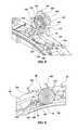
- FIG. 4shows an isometric view of a chip ejection unit of FIG. 3 having portions removed to show a cam shaft and lever assemblies of the chip ejection unit, and also shows a portion of a chip tray of a chip rack, the portion including an opening into the chip tray.
- FIG. 5shows another isometric view of the chip ejection unit of FIG. 3 having additional portions removed to show the cam shaft and lever assemblies of the chip ejection unit.
- FIG. 6shows an isometric detail view of a radially outer portion of the sorting wheel of FIG. 3 holding chips in chip wells of the sorting wheel, a chip ejection unit and a portion of a chip tray holding a chip therein.
- FIG. 7shows another isometric detail view of the radially outer portion of the sorting wheel of FIG. 6 with portions of the chip ejection unit and the portion of the chip tray removed to show finger members of the chip ejection unit in relationship with the chip wells of the sorting wheel when the finger members are positioned within circumferentially extending channels of the sorting wheel.
- FIG. 8shows an isometric detail view of the radially outer portion of the sorting wheel of FIG. 6 and a single cam and finger member of the chip ejection unit to show the relationship between the finger and the sorting wheel when the finger member is positioned outside of a circumferentially extending channel of the sorting wheel.
- FIG. 9shows a cross-sectional detail view of a chip positioned within a chip well of the radially outer portion of the sorting wheel of FIG. 6 , wherein a first and second finger members are positioned within a fist and second circumferentially extending channel of the sorting wheel in a circumferential path of the chip, rotationally preceding the chip.
- FIG. 10shows a cross-sectional detail view of the chip positioned within the chip well of the radially outer portion of the sorting wheel of FIG. 9 , wherein a third finger member is positioned within a third circumferentially extending channel of the sorting wheel in a circumferential path of the chip, rotationally preceding the chip.
- FIG. 11shows a cross-sectional detail view of the chip positioned within the chip well of the radially outer portion of the sorting wheel of FIG. 10 , wherein a fourth finger member is positioned in the circumferential path of the chip, rotationally preceding the chip.
- FIG. 12shows a cross-sectional detail view of the chip positioned within the chip well of the radially outer portion of the sorting wheel of FIG. 11 , wherein the first and second finger members are positioned out of the first and second circumferentially extending channels of the sorting wheel and out of the circumferential path of any chip.
- FIG. 13shows a cross-sectional detail view of the chip positioned within the chip well of the radially outer portion of the sorting wheel of FIG. 12 , wherein the third finger is positioned out of the circumferential path of any chip.
- FIG. 14shows a cross-sectional detail view of the chip positioned within the chip well of the radially outer portion of the sorting wheel of FIG. 13 , wherein the fourth finger is positioned out of the circumferential path of any chip.
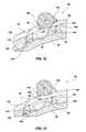
- FIG. 15shows an isometric detail view of the radially outer portion of the sorting wheel, the chip ejection unit and the portion of the chip tray of FIG. 6 without any chips in the chip tray to show the opening into the chip tray.
- FIG. 16shows a cross-sectional detail view of the radially outer portion of the sorting wheel, the chip ejection unit and the portion of the chip tray of FIG. 6 including a chip in the chip tray to show the relationship between components of the chip tray and a chip.
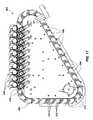
- FIG. 17shows an isometric view of a portion of another chip sorting device, including an articulated conveyor, according to another embodiment of the present invention, with portions removed to show interior components of the chip sorting device.
- FIG. 1An isometric view of a chip sorting device 10 with portions of housings removed to show interior components of the chip sorting device 10 is shown in FIG. 1 .
- the chip sorting device 10may comprise a frame assembly 12 , castors 14 , one or more chip inlet tubes 16 , a chip hopper chamber 18 , a chip sorting chamber 20 , and a chip rack 22 .
- the chip sorting device 10may further include a first chip conveying unit, such as a pre-separator wheel 24 rotatably mounted within the chip hopper chamber 18 , and a second chip conveying unit, such as a sorting wheel 26 rotatably mounted within the chip sorting chamber 20 .
- the pre-separator wheel 24may be positioned on an intermediate wall 28 , which may be viewed more clearly in FIG. 2 , which shows an isometric detail view of the chip sorting device 10 with additional portions of housings removed to show interior components.
- the intermediate wall 28may separate the chip hopper chamber 18 from the chip sorting chamber 20 and an opening 30 formed in the intermediate wall 28 may provide a pathway therebetween.
- the pre-separator wheel 24may be mounted for rotation about a central axis and may include a plurality of radially extending arms 32 defining a plurality of chip wells 34 , 36 .
- Each chip well 34 , 36may be configured to hold a plurality of chips 37 , for example, each chip well 34 , 36 may hold two chips 37 .
- elongated chip wells 34may each hold two chips 37 positioned edge-to-edge, a first chip 37 positioned radially inward of a second chip 37
- deep chip wells 36may hold two chips 37 in a stacked configuration, a first chip 37 positioned axially beneath a second chip 37 .
- elongated chip wells 34 and deep chip wells 36may alternate around the circumference of the pre-separator wheel 24 , which may allow a greater number of chip wells 34 , 36 to be arranged in the pre-separator wheel 24 when compared to an arrangement including only elongated chip wells 34 .
- a motor 38such as one of a stepper motor and a servomotor, may be coupled to the pre-separator wheel 24 , such as by a toothed belt 40 and cogs 42 ( FIG. 1 ), and may be configured to rotate the pre-separator wheel 24 and determine the position of the pre-separator wheel 24 .
- a chip counting device 44may also be included within the chip hopper chamber 18 and may be located near the opening 30 in the intermediate wall 28 , over the circumferential path of the chip wells 34 , 36 as the pre-separator wheel 24 rotates.
- a chip delivery ramp 46( FIG. 2 ) may be attached to the opening 30 in the intermediate wall 28 , extending from the opening 30 and sloping from the intermediate wall 28 into the chip sorting chamber 20 and toward the sorting wheel 26 .
- the sorting wheel 26may be mounted for rotation on the frame assembly 12 about a central axis by a motor 48 , such as one of a stepper motor and a servomotor, coupled to the sorting wheel 26 , such as by a toothed belt 50 and cogs 52 .
- the motor 48may be configured to determine the rotational position of the sorting wheel 26 .
- a chip identification unit 54FIGS. 1 and 2
- a plurality of chip ejection units 56may also be included within the chip sorting chamber 20 .
- the sorting wheel 26may include a plurality of chip wells 58 , each configured to receive a chip 37 therein and transport the chip 37 along a circumferential path.
- the chip identification unit 54may be positioned near the circumferential path of the chip wells 58 of the sorting wheel 26 to identify at least one chip feature and the chip ejection units 56 may be positioned to eject chips 37 from the sorting wheel 26 into the chip rack 22 .
- each chip ejection unit 56may comprise a motor 60 , such as one of a stepper motor and a servomotor, attached to a cam shaft 62 supporting a plurality of cams 64 , such as tri-lobe cams, thereon and a lever shaft 66 supporting a plurality of lever assemblies 68 , 70 , 72 , each lever assembly 68 , 70 , 72 including one or more finger members 74 , 76 , 78 , 80 at one end.
- a first lever assembly 68may include a first finger member 74 and a second finger member 76
- a second lever assembly 70may include a third finger member 78
- a third lever assembly 72may include a fourth finger member 80 .
- the chip rack 22may include a plurality of elongated chip trays 82 , each chip tray 82 of the plurality of elongated chip trays 82 corresponding to a chip ejection unit 56 ( FIG. 3 ), for holding chips 37 ejected from the sorting wheel 26 by the chip ejection units 56 .
- the chip rack 22may include ten chip trays 82 for holding chips 37 in a stacked configuration, one chip 37 stacked axially over another.
- the chip rack 22may further include one or more cutters 84 for separating a predetermined number of chips 37 from a chip tray 82 into a stack and to facilitate the removal of chips 37 from the chip rack 22 .
- the chip sorting device 10may further include a main controller 86 configured to communicate with electrical and electromechanical devices of the chip sorting device 10 , such as the motors 38 , 48 , 60 , the chip counting device 44 , the chip identification unit 54 , drive boards 88 ( FIGS. 2 and 6 ) for the chip ejection units 56 , the cutters 84 , a display and input device, such as a touch screen liquid crystal display (LCD) device 90 .
- the main controller 86may be programmed with software to facilitate the operation of the main controller 86 and the main controller 86 may be configured to facilitate the operation of the chip sorting device 10 and to respond to inputs by a user through the touch screen LCD device 90 .
- a mixture of chips 37 having varied identifying featuresmay be inserted into the chip hopper chamber 18 through one or more of the chip inlet tubes 16 ( FIG. 1 ).
- the chip sorting device 10may be positioned beneath a gaming table (not shown), such as a roulette table, with the chip rack 22 extending from an edge of the gaming table and a chip inlet tube 16 extending to an opening in the surface of the gaming table.
- Chips 37 issued to playersmay have different colors, or other identifying features, which may identify the chips 37 used by each player, identify the denominational value of a chip 37 , and indicate other information as desired.
- an operatormay move mixed chips 37 from the gaming surface to the opening in the gaming table, to be sorted by the chip sorting device 10 .
- the chip sorting device 10may be separate from a gaming table, such as in a counting room of a casino (not shown).
- the mixture of chips 37may come to rest at the bottom of the chip hopper chamber 18 ( FIG. 1 ) of the chip sorting device 10 and may be urged by gravity toward the intermediate wall 28 , which may be situated at about 40 degrees off plumb.
- the pre-separator wheel 24may be rotated along the intermediate wall 28 by the motor 38 ( FIG. 1 ), such as in a counter-clockwise direction, and chips 37 located at the bottom of the chip hopper chamber 18 may become positioned within the chip wells 34 , 36 defined by the radially extending arms 32 of the pre-separator wheel 24 .
- the chips 37 positioned within the chip wells 34 , 36may then be carried in a circumferential path along the intermediate wall 28 by the pre-separator wheel 24 toward the opening 30 in the intermediate wall 28 ( FIG. 2 ).
- the chips 37may be carried past the chip counting device 44 , which may count the number of chips 37 that are positioned within each chip well 34 , 36 and deposited through the opening 30 in the intermediate wall 28 into the chip sorting chamber 20 .
- the chip counting device 44may include one or more optical sensors that may detect the presence of one or more chips 37 within a chip well 34 , 36 .
- a finger member 92may extend into a path of a second axially stacked chip 37 and may temporarily displace the second axially stacked chip 37 radially outward, which may position the chip 37 adjacent to a sensor of the chip counting device 44 and facilitate an accurate counting of the chips 37 within each deep chip well 36 and delivered to the chip sorting chamber 20 .
- the rate of chips 37 delivered to the chip sorting chamber 20may be regulated, such as by controlling the rotational speed of the pre-separator wheel 24 with the motor 38 in response to the number of chips 37 counted by the chip counting device 44 .
- a pre-separator wheel 24 that includes a relatively large number of chip wells 34 , 36 , which may each hold a plurality of chips 37 ,may allow for the delivery of chips 37 to the chip sorting chamber 20 at a relatively high rate, while maintaining a relatively slow rotational speed. This may be advantageous, as the relatively slow movement of the pre-separator wheel 24 may be relatively quiet and may reduce damage that may otherwise be caused to the chips 37 in the chip hopper chamber 18 .
- the chips 37may fall out of the chip wells 34 , 36 onto the chip delivery ramp 46 coupled to the opening 30 within the intermediate wall 28 and may slide down the chip delivery ramp 46 into the chip sorting chamber 20 and toward the sorting wheel 26 . This may allow the chips 37 to be delivered into the chip sorting chamber 20 relatively gently and quietly.
- the chips 37when the chips 37 are delivered into the chip sorting chamber 20 , the chips 37 may become positioned in chip wells 58 of the sorting wheel 26 , which may be positioned about 40 degrees off plumb, similar to the intermediate wall 28 and the pre-separator wheel 24 .
- the chips 37may be urged toward the radially outer edge of the sorting wheel 26 by gravity and inertial forces and each chip 37 may become positioned within an individual chip well 58 of the sorting wheel 26 , which may be rotated in a counter-clockwise direction by the motor 48 ( FIG. 2 ).
- the chips 37may be carried along a circumferential path by the sorting wheel 26 and each chip 37 may be carried past the chip identification unit 54 ( FIG. 2 ), which may be positioned over the circumferential path.
- the chip identification unit 54may classify each chip according to an identifying feature, such as by one or more of a color evaluation device, an RFID reader, an optical sensor, and a laser sensor.
- the chip identification unit 54may include a color line device that may evaluate each chip 37 and identify chips 37 by certain color features that fall within a predetermined color range. By identifying chips 37 that have color features that fall within a predetermined color range, certain chips 37 may be grouped together that have slight variations of color, such as due to inconsistencies in manufacturing the chips 37 , dirt or other debris gathering on the chips 37 , damage to the chips 37 , or other various causes.
- the classification of each analyzed chip 37along with each chip's respective position on the sorting wheel 26 , may then be transmitted to the main controller 86 .
- the main controller 86may then activate specific chip ejection units 56 ( FIG. 3 ) that correspond to each chip classification to be sorted as chips 37 pass the chip ejection units 56 , and the chips 37 may be deposited onto the chip rack 22 ( FIG. 1 ) in separate elongated chip trays 82 , each elongated chip tray 82 corresponding to a specific chip classification.
- the chip wells 58may be defined near the radially outer edge of the sorting wheel 26 by radially segmented guide walls 94 comprising a plurality of wall segments 96 , 98 , 100 , 102 , 104 spaced radially upon the sorting wheel 26 and defining circumferentially extending channels 106 , 108 , 110 , 112 therebetween.
- the chip ejection units 56may comprise finger members 74 , 76 , 78 , 80 sized and positioned to be extended between the wall segments 96 , 98 , 100 , 102 , 104 of radially segmented guide walls 94 into the circumferentially extending channels 106 , 108 , 110 , 112 .
- the finger members 74 , 76 , 78 , 80 of the chip ejection units 56may be positioned axially over the circumferentially extending channels 106 , 108 , 110 , 112 , as shown in FIG. 8 , and may be selectively movable into the channels 106 , 108 , 110 , 112 , as shown in FIG. 7 .
- radially segmented guide walls 94may include a substantially continuous circumferentially extending radially inner wall 96 , a first wall segment 98 , a second wall segment 100 , a third wall segment 102 and fourth wall segment 104 .
- Each wall segment 98 , 100 , 102 , 104may have a leading face 114 , a following face 116 and opposing side faces 118 , the leading faces 114 and following faces 116 defining the chip well 58 , and the opposing side faces 118 defining the circumferentially extending channels 106 , 108 , 110 , 112 .
- a first circumferentially extending channel 106may be defined between the substantially continuous circumferentially extending radially inner wall 96 and the first wall segment 98
- a second circumferentially extending channel 108may be defined between the first wall segment 98 and the second wall segment 100
- a third circumferentially extending channel 110may be defined between the second wall segment 100 and the third wall segment 102
- a fourth circumferentially extending channel 112may be defined between the third wall segment 102 and the fourth wall segment 104 .
- each finger member 74 , 76 , 78 , 80 of the chip ejection unit 56may include a reaction face 120 which may oppose the leading face 114 of each wall segment 98 , 100 , 102 , 104 .
- Each finger member 74 , 76 , 78 , 80 of the chip ejection unit 56may be independently operated by one or more respective cams 64 rotating on one shaft 62 .
- Each cam 64may be mounted to the single cam shaft 62 and the cams 64 may be oriented to move each of the finger members 74 , 76 , 78 , 80 from a first position to a second position, and back to the first position, in a sequence by rotation of the cam shaft 62 with the motor 60 upon receipt of a signal from the main controller 86 .
- each lever assembly 68 , 70 , 72may include an extension lever arm 122 having a first cam follower surface 124 positioned adjacent a first cam 126 and a retraction lever arm 128 having a second cam follower surface 130 adjacent a second cam 132 .
- the first cam follower surface 124 of the extension arm 122may be positioned between the first cam 126 and the sorting wheel 26 .
- the lobe 134may apply a force on the first follower surface 124 of the extension lever 122 and may urge the third finger member 78 toward the sorting wheel 26 and into a circumferentially extending channel 110 thereof. Additionally, the lobe 134 of the first cam 126 may be moved away from the first cam follower surface 124 and a lobe 136 of the second cam 132 may be rotated into contact with the second cam follower surface 130 of the retraction lever arm 128 and may urge the third finger member 78 away from the sorting wheel 26 and out of the circumferentially extending channel 110 thereof.
- a biasing meanssuch as one or more of a torsion spring, a coil spring, a leaf spring, an elastic structure, and a weighted structure, may be utilized to bias the lever assemblies 68 , 70 , 72 , and a single cam and cam follower surface may be utilized to control the position of the finger members 74 , 76 , 78 , 80 .
- a chip ejection unit 56( FIG. 3 ) corresponding to the selected chip tray 82 , which corresponds to the chip classification of the selected chip 37 , may be activated and the first and second finger members 74 , 76 (See FIG.
- first and second circumferentially extending channels 106 , 108may be moved from a first position above the first and second circumferentially extending channels 106 , 108 to a second position within the first circumferentially extending channel 106 , between the substantially continuous circumferentially extending radially inner wall 96 , and the second circumferentially extending channel 108 , between the first wall segment 98 and the second wall segment 100 , circumferentially and rotationally preceding the selected chip 37 , as shown in FIG. 9 .
- an edge of the selected chip 37may come into contact with the reaction faces 120 of the first and second finger members 74 , 76 , which may be positioned within the circumferential path of the selected chip 37 and may be angled to face toward the opening 138 into the selected chip tray 82 of the chip rack 22 and the leading faces 114 of the first and second wall segments 98 , 100 circumferentially trailing the selected chip 37 .
- the reaction faces 120 of the first and second finger members 74 , 76may urge the selected chip 37 both circumferentially toward the leading faces 114 of the first and second wall segments 98 , 100 circumferentially trailing the selected chip 37 and radially outward, toward the opening 138 into the selected chip tray 82 .
- the leading faces 114 of the first and second wall segments 98 , 100 circumferentially trailing the selected chip 37may be angled to face both the reaction faces 120 of the first and second finger members 74 , 76 and the opening 138 into the selected chip tray 82 and may urge the selected chip 37 radially outward, when the selected chip 37 is pushed toward the leading faces 114 of the first and second wall segments 98 , 100 .
- the third finger member 78may then be lowered by the chip ejection unit 56 into the third circumferentially extending channel 110 rotationally preceding the selected chip 37 and within the circumferential path of the selected chip 37 .
- the reaction face 120 of the third finger member 78may cooperate with the leading faces 114 of the second and third wall segments 100 , 102 to urge the selected chip 37 further radially outward, toward the opening 138 into the selected chip tray 82 of the chip rack 22 , as the sorting wheel 26 is further rotated relative to the finger members 74 , 76 , 78 and the selected chip tray 82 .
- the guide walls 140may facilitate the guiding of the selected chip 37 through the opening 138 into the selected chip tray 82 .
- the fourth finger member 80may be lowered by the chip ejection unit 56 into alignment with the fourth circumferentially extending channel 112 rotationally preceding the selected chip 37 and within the circumferential path of the selected chip 37 , as shown in FIG. 11 .
- the reaction face 120 of the fourth finger member 80may cooperate with the leading faces 114 of the third and fourth wall segments 102 , 104 to further urge the selected chip 37 radially outward, toward the opening 138 into the selected chip tray 82 of the chip rack 22 , as the sorting wheel 26 is rotated further.
- the reaction faces 120 of the finger members 74 , 76 , 78 , 80may generally align with a guide wall 140 of the opening 138 into the selected chip tray 82 .
- the first and second finger members 74 , 76may be lifted out, over the first and second circumferentially extending channels 106 , 108 as the selected chip 37 is urged toward the opening 138 into the chip tray 82 by the third and fourth finger members 78 , 80 , as shown in FIG. 12 . This may prevent the reaction faces 120 of the first and second finger members 74 , 76 from contacting a chip in a following chip well 58 that has not been selected to be ejected into the selected chip tray 82 of the chip rack 22 .
- the third and fourth finger members 78 , 80may be independently and sequentially lifted out, over the third and fourth circumferentially extending channels 110 , 112 as the selected chip 37 is urged toward the opening 138 into the selected chip tray 82 , as shown in FIGS. 13 and 14 .
- This ability to independently move certain finger members 74 , 76 , 78 , 80 of the chip ejection unit 56 between a first position and a second positionallows the chip wells 58 of the sorting wheel 26 to be positioned relatively close together, allowing a relatively large number of chip wells 58 to be positioned on the sorting wheel 26 , which increases the rate at which chips 37 are sorted by the chip sorting device 10 .
- each of the finger members 74 , 76 , 78 , 80 of the chip ejection unit 56may remain within the paths of the respective first, second, third and fourth circumferentially extending channels 106 , 108 , 110 , 112 and in a circumferential path of the following selected chip 37 and the following selected chip 37 may be ejected into the selected chip tray 82 of the chip rack 22 .
- any number of following selected chips 37may be ejected in such a manner and the finger members 74 , 76 , 78 , 80 of the chip ejection unit 56 may be moved out of the paths of the circumferentially extending channels 106 , 108 , 110 , 112 when a next rotationally following chip 37 is not selected to be ejected into the selected chip tray 82 of the chip rack 22 .
- the ejection system of the present inventionadvances fingers 74 , 76 , 78 , 80 sequentially such that chips are removed from wells 58 without being struck or jarred. This is an important attribute, as chips formed from clay can easily be damaged during sorting and stacking when the ejectors deliver a concussion-type force to the edge of the chip.
- the ejection systemhas been described above as providing four fingers that move independently, the embodiment described herein provides fingers that move sequentially in response to rotation of a unitary shaft 62 that supports the cams that move the fingers.
- a chip ejection unit 56 for each chip tray 82 of the chip rack 22may allow a plurality of chips 37 positioned within chip wells 58 of the sorting wheel 26 to be substantially simultaneously ejected into a plurality of chip trays 82 of the chip rack 22 .
- each chip tray 82 of the chip rack 22may include a movable barrier 142 located at the opening 138 from the chip sorting chamber 20 and a soft barrier 144 .
- the movable barrier 142may obstruct the opening 138 to the chip tray 82 to prevent the inadvertent ejection of a nonselected chip 37 into the chip tray 82 when a nonselected chip 37 passes the chip tray 82 .
- the movable barrier 142may be moved to a second retracted position, to provide an unobstructed opening 138 into the chip tray 82 .
- the movable barrier 142may return to the original blocking position and may urge the selected chip 37 upward in the chip tray 82 .
- the soft barrier 144may relatively gently stop the movement of the inserted chip 37 at a specified location, upon insertion to the chip tray 82 , and facilitate the arrangement of inserted chips 37 into an axial stack within the chip tray 82 .
- each chip tray 82may include a ramp 146 that may provide a transition between a lower surface 148 and an upper surface 150 , which may be slightly greater than the height of a chip 37 .
- a first selected chip 37may be aligned with the lower surface 148 as the first selected chip 37 enters the opening 138 into the chip tray 82 and may be guided up the ramp 146 during insertion into the chip tray 82 .
- the first selected chip 37may then become aligned with the upper surface 150 and come to rest on the upper surface 150 .
- the second chip 37When a second selected chip 37 may be inserted into the chip tray 82 , the second chip 37 may similarly be aligned with the lower surface 148 as the second chip 37 enters the opening 138 into the chip tray 82 and may be guided up the ramp 146 during insertion into the chip tray 82 . In this manner, the second selected chip 37 may be inserted below the first selected chip 37 , may urge the first selected chip 37 upwards and may come to rest on the upper surface 150 below the first selected chip 37 in an axially stacked arrangement.
- a chip sorting device 200may include another type of chip conveying unit, such as an articulated conveyor 202 , which may be arranged along a fixed path within a chip sorting chamber, as shown in FIG. 17 .
- the articulated conveyor 202may comprise a plurality of articulated link units 206 and each link unit 206 may include a chip well 208 for carrying at least one chip 37 .
- Each chip well 208may be defined by and adjacent to segmented guide walls 210 comprised of a plurality of wall segments 212 and a plurality of channels 214 may be defined between wall segments 212 of the plurality of wall segments 212 .
- the fixed pathmay be arranged such that each link unit 206 , and any chips 37 that may be carried thereby, may travel along a generally straight path (i.e., a substantially linear path) when proximate to chip ejection units 216 and corresponding chip trays 218 of a chip rack.
- a lower and optionally upper edge of the chip rackis linear, to facilitate a close fit to a rectangular notch cut into the roulette table top.
- the wall segments 212 of the plurality of wall segments 212may be spaced laterally along each link unit 206 and may extend longitudinally along each link unit 206 .
- each of the wall segments 212 of the plurality of longitudinally extending wall segments 212may also extend longitudinally along each link unit 206 .
- each of the wall segments 212 of the plurality of wall segments 212 and each of the channels 214may extend along a generally straight path (i.e., a substantially linear path).
- the chip ejection units 216may be similar to the chip ejection units 56 described with reference to FIGS. 1-16 , and the chip ejection units 216 may include similar finger members each configured to be positioned from a first position outside of a longitudinally extending channel 214 , to a second position within a longitudinally extending channel 214 . Additionally, the finger members of the chip ejection units 216 may include reaction faces that may cooperate with leading faces of trailing wall segments 212 to eject chips 37 laterally out of the chip wells 208 (i.e., a chip 37 may be ejected radially with respect to the initial orientation of the chip 37 within the chip well 208 ), similarly to the ejection units 56 described with reference to FIGS. 1-16 .
- each finger member of an ejection unit 216may be positioned within a channel 214 of the articulated conveyor 202 into a linear path of a chip 37 , preceding the chip 37 , and the articulated conveyor 202 may be moved to move the chip 37 into contact with the finger members of the ejection unit 216 . Then, the reaction faces of the finger members of the ejection unit 216 may cooperate with leading faces of trailing wall segments 212 to urge the chip 37 laterally out of the chip well 208 .
Landscapes
- Physics & Mathematics (AREA)
- General Physics & Mathematics (AREA)
- Engineering & Computer Science (AREA)
- Mechanical Engineering (AREA)
- Automatic Analysis And Handling Materials Therefor (AREA)
- Information Retrieval, Db Structures And Fs Structures Therefor (AREA)
Abstract
Description
Claims (15)
Priority Applications (3)
| Application Number | Priority Date | Filing Date | Title |
|---|---|---|---|
| US13/714,843US8757349B2 (en) | 2009-11-02 | 2012-12-14 | Methods of ejecting chips |
| US14/312,227US9384616B2 (en) | 2009-11-02 | 2014-06-23 | Chip handling devices and related methods |
| US14/981,028US9536367B2 (en) | 2009-11-02 | 2015-12-28 | Chip handling devices and related methods |
Applications Claiming Priority (2)
| Application Number | Priority Date | Filing Date | Title |
|---|---|---|---|
| US12/610,974US8336699B2 (en) | 2009-11-02 | 2009-11-02 | Chip sorting devices, components therefor and methods of ejecting chips |
| US13/714,843US8757349B2 (en) | 2009-11-02 | 2012-12-14 | Methods of ejecting chips |
Related Parent Applications (1)
| Application Number | Title | Priority Date | Filing Date |
|---|---|---|---|
| US12/610,974DivisionUS8336699B2 (en) | 2009-11-02 | 2009-11-02 | Chip sorting devices, components therefor and methods of ejecting chips |
Related Child Applications (1)
| Application Number | Title | Priority Date | Filing Date |
|---|---|---|---|
| US14/312,227DivisionUS9384616B2 (en) | 2009-11-02 | 2014-06-23 | Chip handling devices and related methods |
Publications (2)
| Publication Number | Publication Date |
|---|---|
| US20130102236A1 US20130102236A1 (en) | 2013-04-25 |
| US8757349B2true US8757349B2 (en) | 2014-06-24 |
Family
ID=43499894
Family Applications (4)
| Application Number | Title | Priority Date | Filing Date |
|---|---|---|---|
| US12/610,974Active2030-04-21US8336699B2 (en) | 2009-11-02 | 2009-11-02 | Chip sorting devices, components therefor and methods of ejecting chips |
| US13/714,843ActiveUS8757349B2 (en) | 2009-11-02 | 2012-12-14 | Methods of ejecting chips |
| US14/312,227Active2030-03-08US9384616B2 (en) | 2009-11-02 | 2014-06-23 | Chip handling devices and related methods |
| US14/981,028ActiveUS9536367B2 (en) | 2009-11-02 | 2015-12-28 | Chip handling devices and related methods |
Family Applications Before (1)
| Application Number | Title | Priority Date | Filing Date |
|---|---|---|---|
| US12/610,974Active2030-04-21US8336699B2 (en) | 2009-11-02 | 2009-11-02 | Chip sorting devices, components therefor and methods of ejecting chips |
Family Applications After (2)
| Application Number | Title | Priority Date | Filing Date |
|---|---|---|---|
| US14/312,227Active2030-03-08US9384616B2 (en) | 2009-11-02 | 2014-06-23 | Chip handling devices and related methods |
| US14/981,028ActiveUS9536367B2 (en) | 2009-11-02 | 2015-12-28 | Chip handling devices and related methods |
Country Status (4)
| Country | Link |
|---|---|
| US (4) | US8336699B2 (en) |
| EP (1) | EP2497068B1 (en) |
| AR (1) | AR078838A1 (en) |
| WO (1) | WO2011051700A1 (en) |
Cited By (4)
| Publication number | Priority date | Publication date | Assignee | Title |
|---|---|---|---|---|
| US9384616B2 (en) | 2009-11-02 | 2016-07-05 | Shuffle Master Gmbh & Co Kg | Chip handling devices and related methods |
| US9589407B2 (en) | 2003-02-03 | 2017-03-07 | Shuffle Master Gmbh & Co Kg | Apparatus for receiving and sorting disks |
| US9836909B2 (en) | 2016-04-06 | 2017-12-05 | Shuffle Master Gmbh & Co Kg | Chip sorting devices and related assemblies, components and methods |
| US10096192B1 (en) | 2017-08-30 | 2018-10-09 | Shuffle Master Gmbh & Co Kg | Chip sorting devices and related assemblies and methods |
Families Citing this family (7)
| Publication number | Priority date | Publication date | Assignee | Title |
|---|---|---|---|---|
| AT6405U1 (en)* | 2002-06-05 | 2003-10-27 | Card Casinos Austria Res & Dev | CHIP SORTING DEVICE |
| US7934980B2 (en)* | 2002-06-05 | 2011-05-03 | Shuffle Master Gmbh & Co Kg | Chip stack cutter devices for displacing chips in a chip stack and chip-stacking apparatuses including such cutter devices |
| FR2941356B1 (en)* | 2009-01-23 | 2012-08-17 | Gaming Partners Int | GAME PLAY TOILET AND METHOD FOR MANUFACTURING SUCH TOKEN. |
| US8475242B2 (en)* | 2010-08-13 | 2013-07-02 | Gregory F. String | Coin sorting plate with recessed coin slots |
| EP2951795B1 (en)* | 2013-02-04 | 2024-08-07 | Crane Payment Innovations Limited | Conveying money items |
| GB2528287A (en)* | 2014-07-16 | 2016-01-20 | Crane Payment Solutions Ltd | Money item handling device and conveyor |
| US10621816B2 (en)* | 2018-07-24 | 2020-04-14 | Gametec International Limited | Gaming tables for roulette and similar games |
Citations (111)
| Publication number | Priority date | Publication date | Assignee | Title |
|---|---|---|---|---|
| US1200843A (en) | 1912-08-30 | 1916-10-10 | Jay M Johnson | Coin separator and counter. |
| US1241632A (en) | 1915-06-21 | 1917-10-02 | Jay M Johnson | Coin-holder for coin-counting machines. |
| US1813296A (en) | 1927-03-14 | 1931-07-07 | Arthur C Kidwell | Coin separator |
| US1947456A (en) | 1931-11-28 | 1934-02-20 | Sattley Company | Coin handling machine |
| US2020293A (en) | 1934-05-11 | 1935-11-12 | Herman L Adelstein | Sink refuse scoop |
| US2073789A (en) | 1937-03-16 | Apparatus for delivering change | ||
| US2231093A (en) | 1939-03-14 | 1941-02-11 | Automatic Coinwrapping Machine | Article feeder |
| GB720707A (en) | 1953-02-13 | 1954-12-22 | Albert Schuitema | An apparatus for separating and, if desired, sorting flat objects |
| US2904151A (en) | 1957-01-30 | 1959-09-15 | Lloyd F Brogan | Escrow device for coin operated mechanisms |
| US3143118A (en) | 1960-09-26 | 1964-08-04 | Vacuumatic Ltd | Coin sorting apparatus |
| US3371761A (en) | 1966-05-04 | 1968-03-05 | Ryo Hirano | Apparatus for discriminating hard coins |
| US3387616A (en) | 1967-04-10 | 1968-06-11 | Western Stamping Corp | Coin sorting and dispensing device |
| US3435833A (en) | 1967-09-22 | 1969-04-01 | Micro Magnetic Ind Inc | Coin dispenser magazine |
| US3497047A (en) | 1967-10-12 | 1970-02-24 | Clemson Ind Inc | Coin chute |
| US3583410A (en) | 1969-04-25 | 1971-06-08 | Jack E Bayha | Payout mechanism for coin change dispensing apparatus |
| GB1255492A (en) | 1968-02-29 | 1971-12-01 | Brecknell Dolman And Rogers Lt | Coin testing and accepting or rejecting devices |
| US3680566A (en) | 1969-09-22 | 1972-08-01 | Micro Magnetic Ind Inc | Bulk coin dispenser |
| US3766452A (en) | 1972-07-13 | 1973-10-16 | L Burpee | Instrumented token |
| US3771538A (en) | 1971-07-26 | 1973-11-13 | K Reis | Coin sorting and counting machines |
| US3827582A (en) | 1971-12-13 | 1974-08-06 | G Lederer | Stacking device |
| US4010766A (en) | 1975-12-08 | 1977-03-08 | Ncr Corporation | Change dispensing apparatus |
| US4157139A (en) | 1976-12-28 | 1979-06-05 | Bertil Knutsson | Apparatus for sorting and/or handling disc-like members |
| US4161381A (en) | 1976-09-27 | 1979-07-17 | Sciortino August M | Ice cream scoop |
| US4209960A (en) | 1978-08-22 | 1980-07-01 | Sig Schweizerische Industrie-Gesellschaft | Apparatus for maintaining constant the weight of article stacks |
| GB2061490A (en) | 1979-10-17 | 1981-05-13 | Harwood H L | Sorting Coloured Gambling Chips |
| US4275751A (en) | 1979-05-10 | 1981-06-30 | Brandt, Inc. | Coin sorter with expanded capability |
| US4360034A (en) | 1980-04-09 | 1982-11-23 | Joseph C. Gianotti, Trustee | Coin sorter-counter |
| DE3144327A1 (en) | 1981-11-07 | 1983-05-19 | Arthur 6490 Schlüchtern Jahn | Coin-sorting and -counting machine |
| US4427389A (en) | 1982-04-19 | 1984-01-24 | Arco Industries Ltd. | Toy coin changer |
| US4531531A (en) | 1980-11-18 | 1985-07-30 | Ristvedt-Johnson, Inc. | Coin handling machine |
| US4543969A (en) | 1983-05-06 | 1985-10-01 | Cummins-Allison Corporation | Coin sorter apparatus and method utilizing coin thickness as a discriminating parameter |
| US4607649A (en) | 1983-12-21 | 1986-08-26 | Brandt, Inc. | Coin sorter |
| US4681128A (en) | 1986-06-23 | 1987-07-21 | Ristvedt Victor G | Coin sorter |
| US4731043A (en) | 1983-12-14 | 1988-03-15 | Ristvedt-Johnson, Inc. | Coin sorter |
| GB2198274A (en) | 1986-12-03 | 1988-06-08 | Entersword Limited | Coin dispensers |
| US4775354A (en)* | 1987-06-29 | 1988-10-04 | Cummins-Allison Corp. | Coin sorting apparatus with rotating disc stationary guide plate for sorting coins by their different diameters |
| US4863414A (en) | 1986-06-23 | 1989-09-05 | Ristvedt Victor G | Coin sorter |
| US4966570A (en) | 1987-07-30 | 1990-10-30 | Ristvedt Victor G | Coin sorting apparatus for sorting coins of selected denominations |
| US5011456A (en) | 1988-06-22 | 1991-04-30 | Kabushiki Kaisha Nippon Conlux | Coin receiving and discharging apparatus |
| US5011455A (en)* | 1990-02-12 | 1991-04-30 | Cummins-Allison Corporation | Coin sorter with automatic bag-switching |
| US5022889A (en) | 1986-06-23 | 1991-06-11 | Ristvedt Victor G | Coin sorter |
| GB2203582B (en) | 1987-04-16 | 1991-06-19 | Leonard Marmaduke Steele | Coin sorting apparatus |
| US5042810A (en) | 1989-02-13 | 1991-08-27 | Technical Casino Services, Ltd. | Roulette apparatus |
| US5074434A (en) | 1990-11-16 | 1991-12-24 | Himecs Co., Ltd. | Apparatus for dispensing disk-shaped objects |
| US5141443A (en) | 1990-05-14 | 1992-08-25 | Cummins-Allison Corp. | Coin sorter with automatic bag-switching or stopping |
| US5166502A (en) | 1990-01-05 | 1992-11-24 | Trend Plastics, Inc. | Gaming chip with implanted programmable identifier means and process for fabricating same |
| US5207612A (en) | 1991-09-05 | 1993-05-04 | Graham Wollaston | Coin bander |
| DE4240886A1 (en) | 1992-12-04 | 1994-07-21 | Deckert Carl Helmuth | Gambling chips/tokens with built-in bar code unit for games machines |
| CA2090073A1 (en) | 1993-02-22 | 1994-08-23 | Peter Brooke Lovelace Keate | Poker and other gaming chip cleaning and sanitizing device |
| EP0424355B1 (en) | 1989-10-16 | 1994-11-30 | Christian Pohanka | Device for sorting chips at game-tables |
| US5406264A (en) | 1994-04-18 | 1995-04-11 | Sensormatic Electronics Corporation | Gaming chip with magnetic EAS target |
| GB2254419B (en) | 1991-08-06 | 1995-08-02 | Amusement Equip Co Ltd | Sorting of differently identified articles |
| US5460295A (en) | 1994-06-21 | 1995-10-24 | Pez Candy Inc. | Candy dispensing system |
| US5472074A (en) | 1994-03-09 | 1995-12-05 | Milcetic; Duncan J. | Coin operated dispensing machine |
| US5551542A (en) | 1993-12-13 | 1996-09-03 | Stockli; Rudolf | Process and apparatus for identifying coins |
| US5607352A (en) | 1992-11-02 | 1997-03-04 | Asahi Seiko Kabushiki Kaisha | Coin dispensing apparatus |
| EP0631260B1 (en) | 1993-06-22 | 1997-04-09 | Christian Pohanka | Device for centring chips on a stack |
| US5624308A (en) | 1994-09-15 | 1997-04-29 | Standardwerk Eugen Reis Gmbh | System for sorting and/or counting coins by means of a circular sorting track |
| US5651548A (en) | 1995-05-19 | 1997-07-29 | Chip Track International | Gaming chips with electronic circuits scanned by antennas in gaming chip placement areas for tracking the movement of gaming chips within a casino apparatus and method |
| US5735742A (en) | 1995-09-20 | 1998-04-07 | Chip Track International | Gaming table tracking system and method |
| US5757876A (en) | 1997-02-07 | 1998-05-26 | Cosense, Inc. | Object counter and identification system |
| US5755618A (en) | 1995-09-14 | 1998-05-26 | Grips Electronic Gmbh | Apparatus for storing coins or coin-like articles |
| US5770533A (en) | 1994-05-02 | 1998-06-23 | Franchi; John Franco | Open architecture casino operating system |
| FR2749093B1 (en) | 1996-05-24 | 1998-07-10 | Bourgogne Grasset | GAME TABLE MANAGEMENT METHOD AND ELECTRONIC MANAGEMENT SYSTEM FOR USE IN PARTICULAR FOR THE IMPLEMENTATION OF SAID METHOD |
| US5781647A (en) | 1995-10-05 | 1998-07-14 | Digital Biometrics, Inc. | Gambling chip recognition system |
| FR2752078B1 (en) | 1996-07-30 | 1998-10-16 | Gemplus Sca | TOKEN SORTER |
| US5827117A (en) | 1996-05-13 | 1998-10-27 | Mag-Nif Incorporated | Coin sorter and packager |
| US5836583A (en) | 1994-04-26 | 1998-11-17 | Technical Casino Services Ltd. | Detection system for detecting a position of a ball on a roulette wheel |
| EP0806020B1 (en) | 1995-01-24 | 1998-12-30 | Chipper 2000 (Isle of Man) Limited | Colour detection apparatus |
| US5865673A (en) | 1996-01-11 | 1999-02-02 | Cummins-Allison Corp. | Coin sorter |
| US5895321A (en) | 1995-10-09 | 1999-04-20 | Etablissements Bourgogne Et Grasset | Gambling chip |
| GB2333632A (en) | 1998-01-23 | 1999-07-28 | Technical Casino Services Ltd | Disc sorting apparatus and method |
| US5931732A (en) | 1996-05-17 | 1999-08-03 | Asahi Seiko Co., Ltd. | Apparatus for dispensing disks |
| US5933244A (en) | 1995-04-28 | 1999-08-03 | Chipper 2000 (Isle Of Man) Limited | Method of article identification through color determination |
| US5947257A (en) | 1998-01-26 | 1999-09-07 | Schwartz; Melvin | Electronic coin counter for cashier station |
| US5950796A (en) | 1996-04-12 | 1999-09-14 | Asahi Seiko Kabushiki Kaisha | Apparatus for measuring a diameter of a disk body |
| US5957262A (en) | 1995-04-27 | 1999-09-28 | Coinstar, Inc. | Coin counter dejamming method and apparatus |
| US5957776A (en) | 1995-08-09 | 1999-09-28 | Table Trac, Inc. | Table game control system |
| US6021949A (en) | 1994-07-26 | 2000-02-08 | Etablissements Bourgogne Et Grasset | Gambling chip with identification device |
| US6080056A (en) | 1997-12-22 | 2000-06-27 | Scan Coin Industries Ab | Coin handling apparatus and a coin deposit machine incorporating such an apparatus |
| US6139418A (en) | 1998-03-17 | 2000-10-31 | Cummins-Allison Corp. | High speed coin sorter having a reduced size |
| US6168001B1 (en) | 1997-06-27 | 2001-01-02 | Coinstar, Inc. | Positive drive coin discrimination apparatus and method |
| US6186895B1 (en) | 1997-10-07 | 2001-02-13 | Mikohn Gaming Corporation | Intelligent casino chip system and method or use thereof |
| US6193599B1 (en) | 1998-10-20 | 2001-02-27 | Asahi Seiko Co., Ltd. | Coin hopper device |
| US6260757B1 (en) | 1997-10-31 | 2001-07-17 | John M. Strisower | Automatic cashier machine |
| US6264109B1 (en) | 1997-03-10 | 2001-07-24 | Etablissements Bourgogne Et Grasset | Token with electronic chip |
| US6283856B1 (en) | 1999-03-12 | 2001-09-04 | Grips Electronics Ges. M.B.H | Patron and croupier assessment in roulette |
| US6296190B1 (en) | 1999-05-03 | 2001-10-02 | Trend Plastics, Inc. | Gaming chip with transponder and a method for making same |
| US6313871B1 (en) | 1999-02-19 | 2001-11-06 | Casino Software & Services | Apparatus and method for monitoring gambling chips |
| US20020061724A1 (en)* | 2000-11-08 | 2002-05-23 | Tomokazu Nomura | Disk for coin hopper |
| EP1080348B1 (en) | 1998-05-19 | 2002-08-28 | Active Silicon Limited | Method of detecting colours |
| US6532297B1 (en) | 1995-10-05 | 2003-03-11 | Digital Biometrics, Inc. | Gambling chip recognition system |
| US6540602B2 (en) | 2001-02-20 | 2003-04-01 | De La Rue Cash Systems, Inc. | Coin dispenser |
| US6567159B1 (en) | 1999-10-13 | 2003-05-20 | Gaming Analysis, Inc. | System for recognizing a gaming chip and method of use |
| US6572474B2 (en) | 1998-12-04 | 2003-06-03 | Clarence Rudd | Methods of paying winning bets |
| US6581747B1 (en) | 2000-02-15 | 2003-06-24 | Etablissements Bourgogne Et Grasset | Token with an electronic chip and methods for manufacturing the same |
| US6592445B2 (en) | 2001-03-21 | 2003-07-15 | Royal Sovereign, Inc. | Method and apparatus for sorting coins |
| EP0950989B1 (en) | 1998-04-14 | 2003-09-17 | Suzo International (NL) B.V. | Coin guiding device |
| US6629591B1 (en) | 2001-01-12 | 2003-10-07 | Igt | Smart token |
| WO2004009256A1 (en) | 2002-07-19 | 2004-01-29 | Rodney George Johnson | Two stage sorting system suitable for gaming chips |
| US6753830B2 (en) | 1998-09-11 | 2004-06-22 | Visible Tech-Knowledgy, Inc. | Smart electronic label employing electronic ink |
| US20040149539A1 (en) | 2003-02-03 | 2004-08-05 | De Raedt Peter Wolfgang | Apparatus for sorting articles |
| US6772870B2 (en) | 2001-07-26 | 2004-08-10 | Sugai General Industries Ltd. | Token counting and sorting apparatus |
| US20050280212A1 (en) | 2002-06-05 | 2005-12-22 | Ernst Blaha | Counter sorting device |
| US7004831B2 (en) | 2000-09-18 | 2006-02-28 | Glory Kogyo Kabushiki Kaisha | Coin sorting apparatus |
| US7014554B1 (en) | 1996-09-20 | 2006-03-21 | Mars Incorporated | Adaptable coin mechanism |
| US7066335B2 (en) | 2001-12-19 | 2006-06-27 | Pretech As | Apparatus for receiving and distributing cash |
| US20070099553A1 (en)* | 2002-06-05 | 2007-05-03 | Shuffle Master Gmbh & Co Kg | Chip stack cutter devices for displacing chips in a chip stack and chip-stacking apparatuses including such cutter devices, and related methods |
| US7244175B2 (en) | 2002-08-29 | 2007-07-17 | De La Rue Cash Systems Inc. | Coin recycling machine and method |
| US20070212996A1 (en) | 2006-03-13 | 2007-09-13 | Ryou Jeong S | Manual coin sorter |
| WO2011051700A1 (en) | 2009-11-02 | 2011-05-05 | Shuffle Master Gmbh & Co Kg. | Chip sorting devices, components therefor and methods of ejecting chips |
Family Cites Families (13)
| Publication number | Priority date | Publication date | Assignee | Title |
|---|---|---|---|---|
| US2163351A (en)* | 1935-04-02 | 1939-06-20 | Josey P Stacey | Coin sorting machine |
| GB1189658A (en)* | 1966-10-06 | 1970-04-29 | Brecknell Dolman And Rogers Lt | Method and Apparatus for Extracting and Feeding Coins Stored in a Bulk Supply. |
| GB1419609A (en)* | 1974-03-08 | 1975-12-31 | Seeburg Corp | Dispensing device for disc-shaped members |
| JPS5721093Y2 (en)* | 1976-08-18 | 1982-05-07 | ||
| JPH06103511B2 (en) | 1987-06-26 | 1994-12-14 | ユニバーサル販売株式会社 | Coin lifting device |
| SE463700B (en)* | 1988-11-23 | 1991-01-14 | Erik Sjoestroem | SORTING MACHINE MOVES GAMES AND LIKES |
| EP0564452A1 (en) | 1990-12-27 | 1993-10-13 | John Huxley Casino Equipment Ltd | Apparatus for sorting and stacking disc-like objects |
| SE504813C2 (en) | 1995-08-21 | 1997-04-28 | Scan Coin Ab | Machine for counting and sorting coins |
| SE520847C2 (en) | 1999-02-10 | 2003-09-02 | Scan Coin Ind Ab | Coin-separating device, coin-handling apparatus including such device and a method for separating coins |
| US6425817B1 (en) | 2000-04-13 | 2002-07-30 | Blash Momemy | Token counting using scanner |
| NL1019510C2 (en) | 2001-12-06 | 2003-06-10 | Suzo Internat Nl B V | Device for dispensing disc-shaped objects such as coins. |
| ATE541276T1 (en)* | 2005-09-30 | 2012-01-15 | Glory Kogyo Kk | COIN SORTING SYSTEM |
| US7704133B2 (en)* | 2007-08-17 | 2010-04-27 | Talaris Inc. | Method and apparatus for offsorting coins in a coin handling machine |
- 2009
- 2009-11-02USUS12/610,974patent/US8336699B2/enactiveActive
- 2010
- 2010-10-20WOPCT/GB2010/051763patent/WO2011051700A1/enactiveApplication Filing
- 2010-10-20EPEP10773959.1Apatent/EP2497068B1/enactiveActive
- 2010-10-29ARARP100104004Apatent/AR078838A1/ennot_activeApplication Discontinuation
- 2012
- 2012-12-14USUS13/714,843patent/US8757349B2/enactiveActive
- 2014
- 2014-06-23USUS14/312,227patent/US9384616B2/enactiveActive
- 2015
- 2015-12-28USUS14/981,028patent/US9536367B2/enactiveActive
Patent Citations (136)
| Publication number | Priority date | Publication date | Assignee | Title |
|---|---|---|---|---|
| US2073789A (en) | 1937-03-16 | Apparatus for delivering change | ||
| US1200843A (en) | 1912-08-30 | 1916-10-10 | Jay M Johnson | Coin separator and counter. |
| US1241632A (en) | 1915-06-21 | 1917-10-02 | Jay M Johnson | Coin-holder for coin-counting machines. |
| US1813296A (en) | 1927-03-14 | 1931-07-07 | Arthur C Kidwell | Coin separator |
| US1947456A (en) | 1931-11-28 | 1934-02-20 | Sattley Company | Coin handling machine |
| US2020293A (en) | 1934-05-11 | 1935-11-12 | Herman L Adelstein | Sink refuse scoop |
| US2231093A (en) | 1939-03-14 | 1941-02-11 | Automatic Coinwrapping Machine | Article feeder |
| GB720707A (en) | 1953-02-13 | 1954-12-22 | Albert Schuitema | An apparatus for separating and, if desired, sorting flat objects |
| US2904151A (en) | 1957-01-30 | 1959-09-15 | Lloyd F Brogan | Escrow device for coin operated mechanisms |
| US3143118A (en) | 1960-09-26 | 1964-08-04 | Vacuumatic Ltd | Coin sorting apparatus |
| US3371761A (en) | 1966-05-04 | 1968-03-05 | Ryo Hirano | Apparatus for discriminating hard coins |
| US3387616A (en) | 1967-04-10 | 1968-06-11 | Western Stamping Corp | Coin sorting and dispensing device |
| US3435833A (en) | 1967-09-22 | 1969-04-01 | Micro Magnetic Ind Inc | Coin dispenser magazine |
| US3497047A (en) | 1967-10-12 | 1970-02-24 | Clemson Ind Inc | Coin chute |
| GB1255492A (en) | 1968-02-29 | 1971-12-01 | Brecknell Dolman And Rogers Lt | Coin testing and accepting or rejecting devices |
| US3583410A (en) | 1969-04-25 | 1971-06-08 | Jack E Bayha | Payout mechanism for coin change dispensing apparatus |
| US3680566A (en) | 1969-09-22 | 1972-08-01 | Micro Magnetic Ind Inc | Bulk coin dispenser |
| US3771538A (en) | 1971-07-26 | 1973-11-13 | K Reis | Coin sorting and counting machines |
| US3827582A (en) | 1971-12-13 | 1974-08-06 | G Lederer | Stacking device |
| US3766452A (en) | 1972-07-13 | 1973-10-16 | L Burpee | Instrumented token |
| US4010766A (en) | 1975-12-08 | 1977-03-08 | Ncr Corporation | Change dispensing apparatus |
| US4161381A (en) | 1976-09-27 | 1979-07-17 | Sciortino August M | Ice cream scoop |
| US4157139A (en) | 1976-12-28 | 1979-06-05 | Bertil Knutsson | Apparatus for sorting and/or handling disc-like members |
| GB1571219A (en) | 1976-12-28 | 1980-07-09 | Bjoerk S | Devices for sorting members in the form of discs |
| US4209960A (en) | 1978-08-22 | 1980-07-01 | Sig Schweizerische Industrie-Gesellschaft | Apparatus for maintaining constant the weight of article stacks |
| US4275751A (en) | 1979-05-10 | 1981-06-30 | Brandt, Inc. | Coin sorter with expanded capability |
| GB2061490A (en) | 1979-10-17 | 1981-05-13 | Harwood H L | Sorting Coloured Gambling Chips |
| US4360034A (en) | 1980-04-09 | 1982-11-23 | Joseph C. Gianotti, Trustee | Coin sorter-counter |
| US4531531A (en) | 1980-11-18 | 1985-07-30 | Ristvedt-Johnson, Inc. | Coin handling machine |
| DE3144327A1 (en) | 1981-11-07 | 1983-05-19 | Arthur 6490 Schlüchtern Jahn | Coin-sorting and -counting machine |
| US4427389A (en) | 1982-04-19 | 1984-01-24 | Arco Industries Ltd. | Toy coin changer |
| US4543969A (en) | 1983-05-06 | 1985-10-01 | Cummins-Allison Corporation | Coin sorter apparatus and method utilizing coin thickness as a discriminating parameter |
| US4731043A (en) | 1983-12-14 | 1988-03-15 | Ristvedt-Johnson, Inc. | Coin sorter |
| US4607649A (en) | 1983-12-21 | 1986-08-26 | Brandt, Inc. | Coin sorter |
| US4681128A (en) | 1986-06-23 | 1987-07-21 | Ristvedt Victor G | Coin sorter |
| US4863414A (en) | 1986-06-23 | 1989-09-05 | Ristvedt Victor G | Coin sorter |
| US5022889A (en) | 1986-06-23 | 1991-06-11 | Ristvedt Victor G | Coin sorter |
| GB2198274A (en) | 1986-12-03 | 1988-06-08 | Entersword Limited | Coin dispensers |
| GB2203582B (en) | 1987-04-16 | 1991-06-19 | Leonard Marmaduke Steele | Coin sorting apparatus |
| US4775354A (en)* | 1987-06-29 | 1988-10-04 | Cummins-Allison Corp. | Coin sorting apparatus with rotating disc stationary guide plate for sorting coins by their different diameters |
| US4966570A (en) | 1987-07-30 | 1990-10-30 | Ristvedt Victor G | Coin sorting apparatus for sorting coins of selected denominations |
| US5011456A (en) | 1988-06-22 | 1991-04-30 | Kabushiki Kaisha Nippon Conlux | Coin receiving and discharging apparatus |
| US5042810A (en) | 1989-02-13 | 1991-08-27 | Technical Casino Services, Ltd. | Roulette apparatus |
| EP0424355B1 (en) | 1989-10-16 | 1994-11-30 | Christian Pohanka | Device for sorting chips at game-tables |
| US5166502A (en) | 1990-01-05 | 1992-11-24 | Trend Plastics, Inc. | Gaming chip with implanted programmable identifier means and process for fabricating same |
| US5011455A (en)* | 1990-02-12 | 1991-04-30 | Cummins-Allison Corporation | Coin sorter with automatic bag-switching |
| US5141443A (en) | 1990-05-14 | 1992-08-25 | Cummins-Allison Corp. | Coin sorter with automatic bag-switching or stopping |
| US5277651A (en) | 1990-05-14 | 1994-01-11 | Cummins-Allison Corp. | Coin sorter with automatic bag-switching or stopping |
| US5074434A (en) | 1990-11-16 | 1991-12-24 | Himecs Co., Ltd. | Apparatus for dispensing disk-shaped objects |
| US5531331A (en) | 1991-08-06 | 1996-07-02 | Barnett; Adam J. | Sorting of differently identified articles |
| GB2254419B (en) | 1991-08-06 | 1995-08-02 | Amusement Equip Co Ltd | Sorting of differently identified articles |
| US5207612A (en) | 1991-09-05 | 1993-05-04 | Graham Wollaston | Coin bander |
| US5607352A (en) | 1992-11-02 | 1997-03-04 | Asahi Seiko Kabushiki Kaisha | Coin dispensing apparatus |
| DE4240886A1 (en) | 1992-12-04 | 1994-07-21 | Deckert Carl Helmuth | Gambling chips/tokens with built-in bar code unit for games machines |
| CA2090073A1 (en) | 1993-02-22 | 1994-08-23 | Peter Brooke Lovelace Keate | Poker and other gaming chip cleaning and sanitizing device |
| EP0631260B1 (en) | 1993-06-22 | 1997-04-09 | Christian Pohanka | Device for centring chips on a stack |
| US5551542A (en) | 1993-12-13 | 1996-09-03 | Stockli; Rudolf | Process and apparatus for identifying coins |
| US5472074A (en) | 1994-03-09 | 1995-12-05 | Milcetic; Duncan J. | Coin operated dispensing machine |
| US5406264A (en) | 1994-04-18 | 1995-04-11 | Sensormatic Electronics Corporation | Gaming chip with magnetic EAS target |
| EP0757582B1 (en) | 1994-04-26 | 1999-06-23 | TOWERS, Paul | A detection system |
| US5836583A (en) | 1994-04-26 | 1998-11-17 | Technical Casino Services Ltd. | Detection system for detecting a position of a ball on a roulette wheel |
| US5770533A (en) | 1994-05-02 | 1998-06-23 | Franchi; John Franco | Open architecture casino operating system |
| US5460295A (en) | 1994-06-21 | 1995-10-24 | Pez Candy Inc. | Candy dispensing system |
| US6021949A (en) | 1994-07-26 | 2000-02-08 | Etablissements Bourgogne Et Grasset | Gambling chip with identification device |
| US5624308A (en) | 1994-09-15 | 1997-04-29 | Standardwerk Eugen Reis Gmbh | System for sorting and/or counting coins by means of a circular sorting track |
| CA2229054C (en) | 1995-01-24 | 2006-11-07 | Chipper 2000 (Isle Of Man) Limited | Colour detection apparatus |
| EP0806020B1 (en) | 1995-01-24 | 1998-12-30 | Chipper 2000 (Isle of Man) Limited | Colour detection apparatus |
| US6075217A (en) | 1995-01-24 | 2000-06-13 | Chipper 2000 Limited | Color detection apparatus |
| US5957262A (en) | 1995-04-27 | 1999-09-28 | Coinstar, Inc. | Coin counter dejamming method and apparatus |
| EP0823041B1 (en) | 1995-04-28 | 2002-09-04 | Technical Casino Services Limited | Colour detection method |
| US5933244A (en) | 1995-04-28 | 1999-08-03 | Chipper 2000 (Isle Of Man) Limited | Method of article identification through color determination |
| CA2229053C (en) | 1995-04-28 | 2006-11-14 | Chipper 2000 (Isle Of Man) Limited | Colour detection method |
| US5651548A (en) | 1995-05-19 | 1997-07-29 | Chip Track International | Gaming chips with electronic circuits scanned by antennas in gaming chip placement areas for tracking the movement of gaming chips within a casino apparatus and method |
| US5957776A (en) | 1995-08-09 | 1999-09-28 | Table Trac, Inc. | Table game control system |
| US5755618A (en) | 1995-09-14 | 1998-05-26 | Grips Electronic Gmbh | Apparatus for storing coins or coin-like articles |
| US5735742A (en) | 1995-09-20 | 1998-04-07 | Chip Track International | Gaming table tracking system and method |
| US6532297B1 (en) | 1995-10-05 | 2003-03-11 | Digital Biometrics, Inc. | Gambling chip recognition system |
| US5781647A (en) | 1995-10-05 | 1998-07-14 | Digital Biometrics, Inc. | Gambling chip recognition system |
| US5895321A (en) | 1995-10-09 | 1999-04-20 | Etablissements Bourgogne Et Grasset | Gambling chip |
| US5865673A (en) | 1996-01-11 | 1999-02-02 | Cummins-Allison Corp. | Coin sorter |
| US5950796A (en) | 1996-04-12 | 1999-09-14 | Asahi Seiko Kabushiki Kaisha | Apparatus for measuring a diameter of a disk body |
| US5827117A (en) | 1996-05-13 | 1998-10-27 | Mag-Nif Incorporated | Coin sorter and packager |
| US5931732A (en) | 1996-05-17 | 1999-08-03 | Asahi Seiko Co., Ltd. | Apparatus for dispensing disks |
| FR2749093B1 (en) | 1996-05-24 | 1998-07-10 | Bourgogne Grasset | GAME TABLE MANAGEMENT METHOD AND ELECTRONIC MANAGEMENT SYSTEM FOR USE IN PARTICULAR FOR THE IMPLEMENTATION OF SAID METHOD |
| FR2752078B1 (en) | 1996-07-30 | 1998-10-16 | Gemplus Sca | TOKEN SORTER |
| US7014554B1 (en) | 1996-09-20 | 2006-03-21 | Mars Incorporated | Adaptable coin mechanism |
| US5757876A (en) | 1997-02-07 | 1998-05-26 | Cosense, Inc. | Object counter and identification system |
| US6264109B1 (en) | 1997-03-10 | 2001-07-24 | Etablissements Bourgogne Et Grasset | Token with electronic chip |
| US6168001B1 (en) | 1997-06-27 | 2001-01-02 | Coinstar, Inc. | Positive drive coin discrimination apparatus and method |
| US6186895B1 (en) | 1997-10-07 | 2001-02-13 | Mikohn Gaming Corporation | Intelligent casino chip system and method or use thereof |
| US6464584B2 (en) | 1997-10-07 | 2002-10-15 | Mikohn Gaming Corporation | Intelligent casino chip system and method for use thereof |
| US6260757B1 (en) | 1997-10-31 | 2001-07-17 | John M. Strisower | Automatic cashier machine |
| US6080056A (en) | 1997-12-22 | 2000-06-27 | Scan Coin Industries Ab | Coin handling apparatus and a coin deposit machine incorporating such an apparatus |
| EP1050024B1 (en) | 1998-01-23 | 2004-03-03 | Technical Casino Services Limited | Disc sorting apparatus and method |
| US6381294B1 (en) | 1998-01-23 | 2002-04-30 | Technical Casino Services Ltd. | Disc sorting apparatus and method |
| GB2333632A (en) | 1998-01-23 | 1999-07-28 | Technical Casino Services Ltd | Disc sorting apparatus and method |
| US5947257A (en) | 1998-01-26 | 1999-09-07 | Schwartz; Melvin | Electronic coin counter for cashier station |
| US6139418A (en) | 1998-03-17 | 2000-10-31 | Cummins-Allison Corp. | High speed coin sorter having a reduced size |
| EP0950989B1 (en) | 1998-04-14 | 2003-09-17 | Suzo International (NL) B.V. | Coin guiding device |
| EP1080348B1 (en) | 1998-05-19 | 2002-08-28 | Active Silicon Limited | Method of detecting colours |
| US6753830B2 (en) | 1998-09-11 | 2004-06-22 | Visible Tech-Knowledgy, Inc. | Smart electronic label employing electronic ink |
| US6193599B1 (en) | 1998-10-20 | 2001-02-27 | Asahi Seiko Co., Ltd. | Coin hopper device |
| US6572474B2 (en) | 1998-12-04 | 2003-06-03 | Clarence Rudd | Methods of paying winning bets |
| US6313871B1 (en) | 1999-02-19 | 2001-11-06 | Casino Software & Services | Apparatus and method for monitoring gambling chips |
| US6506115B1 (en) | 1999-03-12 | 2003-01-14 | Grips Electronics Ges. M.B.H. | Method of estimating the performance of a croupier at a roulette table |
| US6283856B1 (en) | 1999-03-12 | 2001-09-04 | Grips Electronics Ges. M.B.H | Patron and croupier assessment in roulette |
| US6733388B2 (en) | 1999-03-12 | 2004-05-11 | Grips Electronics Ges.M.B.H | Patron and croupier assessment in roulette |
| US6296190B1 (en) | 1999-05-03 | 2001-10-02 | Trend Plastics, Inc. | Gaming chip with transponder and a method for making same |
| US6567159B1 (en) | 1999-10-13 | 2003-05-20 | Gaming Analysis, Inc. | System for recognizing a gaming chip and method of use |
| US6581747B1 (en) | 2000-02-15 | 2003-06-24 | Etablissements Bourgogne Et Grasset | Token with an electronic chip and methods for manufacturing the same |
| US7004831B2 (en) | 2000-09-18 | 2006-02-28 | Glory Kogyo Kabushiki Kaisha | Coin sorting apparatus |
| US20020061724A1 (en)* | 2000-11-08 | 2002-05-23 | Tomokazu Nomura | Disk for coin hopper |
| US6629591B1 (en) | 2001-01-12 | 2003-10-07 | Igt | Smart token |
| US6540602B2 (en) | 2001-02-20 | 2003-04-01 | De La Rue Cash Systems, Inc. | Coin dispenser |
| US6592445B2 (en) | 2001-03-21 | 2003-07-15 | Royal Sovereign, Inc. | Method and apparatus for sorting coins |
| US6772870B2 (en) | 2001-07-26 | 2004-08-10 | Sugai General Industries Ltd. | Token counting and sorting apparatus |
| US7066335B2 (en) | 2001-12-19 | 2006-06-27 | Pretech As | Apparatus for receiving and distributing cash |
| US20070099553A1 (en)* | 2002-06-05 | 2007-05-03 | Shuffle Master Gmbh & Co Kg | Chip stack cutter devices for displacing chips in a chip stack and chip-stacking apparatuses including such cutter devices, and related methods |
| US8006847B2 (en) | 2002-06-05 | 2011-08-30 | Shuffle Master Gmbh & Co Kg | Chip sorting device |
| US7934980B2 (en) | 2002-06-05 | 2011-05-03 | Shuffle Master Gmbh & Co Kg | Chip stack cutter devices for displacing chips in a chip stack and chip-stacking apparatuses including such cutter devices |
| US7861868B2 (en) | 2002-06-05 | 2011-01-04 | Shuffle Master Gmbh & Co Kg | Chip sorting and stacking devices |
| US20050280212A1 (en) | 2002-06-05 | 2005-12-22 | Ernst Blaha | Counter sorting device |
| WO2004009256A1 (en) | 2002-07-19 | 2004-01-29 | Rodney George Johnson | Two stage sorting system suitable for gaming chips |
| US7244175B2 (en) | 2002-08-29 | 2007-07-17 | De La Rue Cash Systems Inc. | Coin recycling machine and method |
| US20040149539A1 (en) | 2003-02-03 | 2004-08-05 | De Raedt Peter Wolfgang | Apparatus for sorting articles |
| US7201268B2 (en) | 2003-02-03 | 2007-04-10 | Streamline Innovations Gmbh | Apparatus for sorting articles |
| US7028826B2 (en) | 2003-02-03 | 2006-04-18 | Streamline Innovations Gmbh | Apparatus for sorting articles |
| US7681708B2 (en) | 2003-02-03 | 2010-03-23 | Shuffle Master Gmbh & Co Kg | Apparatus for sorting articles |
| US6976589B2 (en) | 2003-02-03 | 2005-12-20 | Streamline Innovations Gmbh | Apparatus for sorting articles |
| US20050155838A1 (en) | 2003-02-03 | 2005-07-21 | Raedt Peter W.D. | Apparatus for sorting articles |
| WO2004069431A2 (en) | 2003-02-03 | 2004-08-19 | Ludo De Meutter | Apparatus for sorting articles |
| US8298052B2 (en) | 2003-02-03 | 2012-10-30 | Shuffle Master Gmbh & Co Kg | Apparatus for sorting articles |
| US20070212996A1 (en) | 2006-03-13 | 2007-09-13 | Ryou Jeong S | Manual coin sorter |
| WO2008046561A1 (en) | 2006-10-19 | 2008-04-24 | Shuffle Master Gmbh & Co.Kg | Chip stack cutter devices for displacing chips in a chip stack and chip-stacking apparatuses including such cutter devices, and related methods |
| WO2011051700A1 (en) | 2009-11-02 | 2011-05-05 | Shuffle Master Gmbh & Co Kg. | Chip sorting devices, components therefor and methods of ejecting chips |
| US8336699B2 (en) | 2009-11-02 | 2012-12-25 | Shuffle Master Gmbh & Co Kg | Chip sorting devices, components therefor and methods of ejecting chips |
Non-Patent Citations (18)
| Title |
|---|
| Chipmaster Training handouts from Jan. 1994 (author unknown). |
| Cover sheet of 1993 video tape describing the Chipmaster (author unknown). |
| Huxley's advertisement for Chipmaster: Huxley's count on the Chipmaster deal, ("Casino World" is distributed in the U.S.) Mar. 1994 (author unknown). |
| International Preliminary Report for Application No. PCT/EP2007/008873, dated Apr. 22, 2009, 6 pages. |
| International Preliminary Report for Application No. PCT/US04/02331, dated Dec. 14, 2006 (3 pages). |
| International Search Report dated Mar. 6, 2008, for International Application No. PCT/EP2007/008873 (2 pages). |
| PCT International Search Report and Written Opinion of the International Searching Authority for PCT/GB2010/051763, dated Mar. 30, 2011, 14 pages. |
| PCT International Search Report for International Application No. PCT/US04/02331 dated Jun. 23, 2006 (2 pages). |
| Photograph of Chipmaster production at VICOMA, Vienna, Jan. 4, 2005 (photographer unknown). |
| Photograph of first Chipmaster installation at Casino Baden (Austria), Jan. 4, 2004 (photographer unknown). |
| Photograph of first Chipmaster installation at Holland Casinos, Jan. 4, 2004 (photographer unknown). |
| Photograph of first Chipmaster installation at Valencia (Spain), Jan. 4, 2004 (photographer unknown). |
| Photographs of Chipmaster in Paulson Booth at Apr. 26-27, 1994 Show (photographer unknown). |
| Report from Spain regarding Chipmaster by Christina Pohanka, Sep. 26, 1993. |
| Show report for Chipmaster in Monte Carlo by Christian Pohanka, Mar. 23, 1993, (4 pages). |
| Trial installation of Chipmaster at Holland Casinos, report by Christian Pohanka, Sep. 29, 1993, (2 pages). |
| Written Opinion for Application No. PCT/EP2007/008873, dated Mar. 6, 2008, 5 pages. |
| Written Opinion for Application No. PCT/US04/02331, dated Jun. 23, 2006 (3 pages). |
Cited By (8)
| Publication number | Priority date | Publication date | Assignee | Title |
|---|---|---|---|---|
| US9589407B2 (en) | 2003-02-03 | 2017-03-07 | Shuffle Master Gmbh & Co Kg | Apparatus for receiving and sorting disks |
| US9990792B2 (en) | 2003-02-03 | 2018-06-05 | Shuffle Master Gmbh & Co Kg | Methods and apparatus for receiving and sorting disks |
| US10706656B2 (en) | 2003-02-03 | 2020-07-07 | Shuffle Master Gmbh & Co Kg | Methods and apparatus for receiving and sorting disks |
| US9384616B2 (en) | 2009-11-02 | 2016-07-05 | Shuffle Master Gmbh & Co Kg | Chip handling devices and related methods |
| US9536367B2 (en) | 2009-11-02 | 2017-01-03 | Shuffle Master Gmbh & Co Kg | Chip handling devices and related methods |
| US9836909B2 (en) | 2016-04-06 | 2017-12-05 | Shuffle Master Gmbh & Co Kg | Chip sorting devices and related assemblies, components and methods |
| US10255741B2 (en) | 2016-04-06 | 2019-04-09 | Shuffle Master Gmbh & Co Kg | Chip sorting devices and related assemblies, components and methods |
| US10096192B1 (en) | 2017-08-30 | 2018-10-09 | Shuffle Master Gmbh & Co Kg | Chip sorting devices and related assemblies and methods |
Also Published As
| Publication number | Publication date |
|---|---|
| US9536367B2 (en) | 2017-01-03 |
| WO2011051700A4 (en) | 2011-07-21 |
| US20110105002A1 (en) | 2011-05-05 |
| US20130102236A1 (en) | 2013-04-25 |
| EP2497068B1 (en) | 2020-08-26 |
| US9384616B2 (en) | 2016-07-05 |
| US20140302762A1 (en) | 2014-10-09 |
| AR078838A1 (en) | 2011-12-07 |
| EP2497068A1 (en) | 2012-09-12 |
| US8336699B2 (en) | 2012-12-25 |
| US20160107846A1 (en) | 2016-04-21 |
| WO2011051700A1 (en) | 2011-05-05 |
Similar Documents
| Publication | Publication Date | Title |
|---|---|---|
| US9536367B2 (en) | Chip handling devices and related methods | |
| US9589407B2 (en) | Apparatus for receiving and sorting disks | |
| US20240102794A1 (en) | Card-handling devices with defect detection and related methods | |
| EP2076890B1 (en) | Chip stack cutter devices for displacing chips in a chip stack and chip-stacking apparatuses including such cutter devices, and related methods | |
| US7658668B2 (en) | Coin handling equipment | |
| US20240108968A1 (en) | Card-handling devices and related methods, assemblies, and components | |
| US8092284B2 (en) | Coin handling equipment | |
| KR0138238B1 (en) | Unacceptable coin removing device of coin handling machine | |
| JP5775776B2 (en) | Coin feeding device, coin depositing and dispensing machine and coin feeding method | |
| GB2061490A (en) | Sorting Coloured Gambling Chips | |
| US8961275B2 (en) | Coin depositing and dispensing machine | |
| WO1992011953A1 (en) | Apparatus for sorting and stacking disc-like objects | |
| CN112839724A (en) | Card handling device and related methods, assemblies and components | |
| WO2004009256A1 (en) | Two stage sorting system suitable for gaming chips | |
| WO1988001082A1 (en) | Sorting coins, tokens and the like | |
| JP6056586B2 (en) | Coin processing equipment | |
| CN113326905B (en) | Intelligent card information processing equipment | |
| WO2019042988A2 (en) | Chip sorting devices and related assemblies and methods | |
| JP5985715B2 (en) | Coin feeding device, coin depositing and dispensing machine and coin feeding method | |
| JP2020052743A (en) | Coin processing equipment |
Legal Events
| Date | Code | Title | Description |
|---|---|---|---|
| AS | Assignment | Owner name:SHUFFLE MASTER GMBH & CO KG, AUSTRIA Free format text:ASSIGNMENT OF ASSIGNORS INTEREST;ASSIGNORS:BLAHA, ERNST;KRENN, PETER;REEL/FRAME:029607/0789 Effective date:20090902 | |
| FEPP | Fee payment procedure | Free format text:PAYOR NUMBER ASSIGNED (ORIGINAL EVENT CODE: ASPN); ENTITY STATUS OF PATENT OWNER: LARGE ENTITY | |
| AS | Assignment | Owner name:SHUFFLE MASTER GMBH & CO KG, AUSTRIA Free format text:ASSIGNMENT OF ASSIGNORS INTEREST;ASSIGNORS:BLAHA, ERNST;KRENN, PETER;REEL/FRAME:032440/0760 Effective date:20140306 | |
| STCF | Information on status: patent grant | Free format text:PATENTED CASE | |
| AS | Assignment | Owner name:DEUTSCHE BANK TRUST COMPANY AMERICAS, AS COLLATERAL AGENT, NEW YORK Free format text:SECURITY AGREEMENT;ASSIGNORS:SCIENTIFIC GAMES INTERNATIONAL, INC.;BALLY GAMING, INC.;REEL/FRAME:044889/0662 Effective date:20171214 Owner name:DEUTSCHE BANK TRUST COMPANY AMERICAS, AS COLLATERA Free format text:SECURITY AGREEMENT;ASSIGNORS:SCIENTIFIC GAMES INTERNATIONAL, INC.;BALLY GAMING, INC.;REEL/FRAME:044889/0662 Effective date:20171214 | |
| MAFP | Maintenance fee payment | Free format text:PAYMENT OF MAINTENANCE FEE, 4TH YEAR, LARGE ENTITY (ORIGINAL EVENT CODE: M1551) Year of fee payment:4 | |
| AS | Assignment | Owner name:DEUTSCHE BANK TRUST COMPANY AMERICAS, AS COLLATERAL AGENT, NEW YORK Free format text:SECURITY AGREEMENT;ASSIGNORS:SCIENTIFIC GAMES INTERNATIONAL, INC.;BALLY GAMING, INC.;REEL/FRAME:045909/0513 Effective date:20180409 Owner name:DEUTSCHE BANK TRUST COMPANY AMERICAS, AS COLLATERA Free format text:SECURITY AGREEMENT;ASSIGNORS:SCIENTIFIC GAMES INTERNATIONAL, INC.;BALLY GAMING, INC.;REEL/FRAME:045909/0513 Effective date:20180409 | |
| AS | Assignment | Owner name:SG GAMING, INC., NEVADA Free format text:CHANGE OF NAME;ASSIGNOR:BALLY GAMING, INC.;REEL/FRAME:051643/0044 Effective date:20200103 | |
| MAFP | Maintenance fee payment | Free format text:PAYMENT OF MAINTENANCE FEE, 8TH YEAR, LARGE ENTITY (ORIGINAL EVENT CODE: M1552); ENTITY STATUS OF PATENT OWNER: LARGE ENTITY Year of fee payment:8 | |
| AS | Assignment | Owner name:JPMORGAN CHASE BANK, N.A., NEW YORK Free format text:SECURITY AGREEMENT;ASSIGNOR:SG GAMING INC.;REEL/FRAME:059793/0001 Effective date:20220414 | |
| AS | Assignment | Owner name:JPMORGAN CHASE BANK, N.A., AS COLLATERAL AGENT, NEW YORK Free format text:SECURITY AGREEMENT;ASSIGNOR:LNW GAMING, INC.;REEL/FRAME:071340/0404 Effective date:20250521 |