US8756785B2 - Surgical instrument shafts and methods of manufacturing shafts for surgical instruments - Google Patents
Surgical instrument shafts and methods of manufacturing shafts for surgical instrumentsDownload PDFInfo
- Publication number
- US8756785B2 US8756785B2US13/248,976US201113248976AUS8756785B2US 8756785 B2US8756785 B2US 8756785B2US 201113248976 AUS201113248976 AUS 201113248976AUS 8756785 B2US8756785 B2US 8756785B2
- Authority
- US
- United States
- Prior art keywords
- segment
- shaft
- proximal
- distal
- welding
- Prior art date
- Legal status (The legal status is an assumption and is not a legal conclusion. Google has not performed a legal analysis and makes no representation as to the accuracy of the status listed.)
- Active, expires
Links
Images


Classifications
- A—HUMAN NECESSITIES
- A61—MEDICAL OR VETERINARY SCIENCE; HYGIENE
- A61B—DIAGNOSIS; SURGERY; IDENTIFICATION
- A61B17/00—Surgical instruments, devices or methods
- A61B17/28—Surgical forceps
- A—HUMAN NECESSITIES
- A61—MEDICAL OR VETERINARY SCIENCE; HYGIENE
- A61B—DIAGNOSIS; SURGERY; IDENTIFICATION
- A61B18/00—Surgical instruments, devices or methods for transferring non-mechanical forms of energy to or from the body
- A61B18/04—Surgical instruments, devices or methods for transferring non-mechanical forms of energy to or from the body by heating
- A61B18/12—Surgical instruments, devices or methods for transferring non-mechanical forms of energy to or from the body by heating by passing a current through the tissue to be heated, e.g. high-frequency current
- A61B18/14—Probes or electrodes therefor
- A61B18/1442—Probes having pivoting end effectors, e.g. forceps
- A61B18/1445—Probes having pivoting end effectors, e.g. forceps at the distal end of a shaft, e.g. forceps or scissors at the end of a rigid rod
- B—PERFORMING OPERATIONS; TRANSPORTING
- B23—MACHINE TOOLS; METAL-WORKING NOT OTHERWISE PROVIDED FOR
- B23K—SOLDERING OR UNSOLDERING; WELDING; CLADDING OR PLATING BY SOLDERING OR WELDING; CUTTING BY APPLYING HEAT LOCALLY, e.g. FLAME CUTTING; WORKING BY LASER BEAM
- B23K20/00—Non-electric welding by applying impact or other pressure, with or without the application of heat, e.g. cladding or plating
- B23K20/12—Non-electric welding by applying impact or other pressure, with or without the application of heat, e.g. cladding or plating the heat being generated by friction; Friction welding
- B23K20/129—Non-electric welding by applying impact or other pressure, with or without the application of heat, e.g. cladding or plating the heat being generated by friction; Friction welding specially adapted for particular articles or workpieces
- B—PERFORMING OPERATIONS; TRANSPORTING
- B23—MACHINE TOOLS; METAL-WORKING NOT OTHERWISE PROVIDED FOR
- B23K—SOLDERING OR UNSOLDERING; WELDING; CLADDING OR PLATING BY SOLDERING OR WELDING; CUTTING BY APPLYING HEAT LOCALLY, e.g. FLAME CUTTING; WORKING BY LASER BEAM
- B23K26/00—Working by laser beam, e.g. welding, cutting or boring
- B23K26/12—Working by laser beam, e.g. welding, cutting or boring in a special atmosphere, e.g. in an enclosure
- B23K26/123—Working by laser beam, e.g. welding, cutting or boring in a special atmosphere, e.g. in an enclosure in an atmosphere of particular gases
- B—PERFORMING OPERATIONS; TRANSPORTING
- B23—MACHINE TOOLS; METAL-WORKING NOT OTHERWISE PROVIDED FOR
- B23K—SOLDERING OR UNSOLDERING; WELDING; CLADDING OR PLATING BY SOLDERING OR WELDING; CUTTING BY APPLYING HEAT LOCALLY, e.g. FLAME CUTTING; WORKING BY LASER BEAM
- B23K26/00—Working by laser beam, e.g. welding, cutting or boring
- B23K26/20—Bonding
- B23K26/21—Bonding by welding
- B—PERFORMING OPERATIONS; TRANSPORTING
- B23—MACHINE TOOLS; METAL-WORKING NOT OTHERWISE PROVIDED FOR
- B23P—METAL-WORKING NOT OTHERWISE PROVIDED FOR; COMBINED OPERATIONS; UNIVERSAL MACHINE TOOLS
- B23P11/00—Connecting or disconnecting metal parts or objects by metal-working techniques not otherwise provided for
- A—HUMAN NECESSITIES
- A61—MEDICAL OR VETERINARY SCIENCE; HYGIENE
- A61B—DIAGNOSIS; SURGERY; IDENTIFICATION
- A61B17/00—Surgical instruments, devices or methods
- A61B2017/00526—Methods of manufacturing
- B—PERFORMING OPERATIONS; TRANSPORTING
- B21—MECHANICAL METAL-WORKING WITHOUT ESSENTIALLY REMOVING MATERIAL; PUNCHING METAL
- B21D—WORKING OR PROCESSING OF SHEET METAL OR METAL TUBES, RODS OR PROFILES WITHOUT ESSENTIALLY REMOVING MATERIAL; PUNCHING METAL
- B21D35/00—Combined processes according to or processes combined with methods covered by groups B21D1/00 - B21D31/00
- B21D35/002—Processes combined with methods covered by groups B21D1/00 - B21D31/00
- Y—GENERAL TAGGING OF NEW TECHNOLOGICAL DEVELOPMENTS; GENERAL TAGGING OF CROSS-SECTIONAL TECHNOLOGIES SPANNING OVER SEVERAL SECTIONS OF THE IPC; TECHNICAL SUBJECTS COVERED BY FORMER USPC CROSS-REFERENCE ART COLLECTIONS [XRACs] AND DIGESTS
- Y10—TECHNICAL SUBJECTS COVERED BY FORMER USPC
- Y10T—TECHNICAL SUBJECTS COVERED BY FORMER US CLASSIFICATION
- Y10T29/00—Metal working
- Y10T29/49—Method of mechanical manufacture
- Y10T29/49826—Assembling or joining
- Y10T29/49904—Assembling a subassembly, then assembling with a second subassembly
Definitions
- the present disclosurerelates to surgical instruments and, more particularly, to surgical forceps for grasping, sealing, and/or dividing tissue.
- a forcepsis a plier-like instrument which relies on mechanical action between its jaws to grasp, clamp and constrict vessels or tissue. Electrosurgical forceps utilize both mechanical clamping action and electrical energy to affect hemostasis by heating tissue and blood vessels to coagulate and/or cauterize tissue. Certain surgical procedures require more than simply cauterizing tissue and rely on the unique combination of clamping pressure, precise electrosurgical energy control and gap distance (i.e., distance between opposing jaw members when closed about tissue) to “seal” tissue, vessels and certain vascular bundles. Typically, once a vessel is sealed, the surgeon has to accurately sever the vessel along the newly formed tissue seal. Accordingly, many vessel sealing instruments have been designed which incorporate a knife or blade member that effectively severs the tissue after forming a tissue seal.
- An endoscopic surgical forcepstypically includes an elongated shaft having an end effector assembly, e.g., a pair of jaw members, disposed at the distal end thereof.
- the elongated shaftpermits the surgeon to insert the end effector assembly through a relatively small access opening in the body to the internal surgical site, while the housing of the endoscopic forceps remains disposed externally of the surgical site. The surgeon may then control the operation of the end effector assembly, e.g., to grasp, seal, and/or divide tissue, by manipulating the housing.
- the shafts of surgical instrumentstypically include numerous mechanical features at the ends thereof to facilitate operative engagement of the end effector assembly to the shaft at one end thereof and the housing, or handle assembly at the other end thereof such that the surgeon may operate the end effector assembly by manipulating mechanical components coupled to the housing.
- distalrefers to the portion that is being described which is further from a user
- proximalrefers to the portion that is being described which is closer to a user
- a method of manufacturing a shaft of a surgical instrumentincludes forming a proximal segment of the shaft to include one or more features for operably engaging the shaft to a first component of the surgical instrument, forming a distal segment of the shaft to include one or more features for operably engaging the shaft to a second component of the surgical instrument, and forming an intermediate segment of the shaft.
- the proximal segment of the shaftis welded to a proximal end of the intermediate segment and the distal end of the shaft is welded to a distal end of the intermediate segment.
- the welding of the proximal segment and/or the distal segment to the intermediate segmentis configured such that the feature(s) of each of the proximal and distal segments are aligned in a pre-determined orientation relative to one another.
- the proximal segment and/or the distal segmentare welded to the intermediate segment via laser welding.
- the proximal segment and/or the distal segmentmay be welded to the intermediate segment via spin-welding, or one of the proximal and distal segments may be welded via laser welding, while the other is welded via spin-welding.
- the welding of the proximal segment and the welding of the distal segment to the proximal and distal ends of the intermediate segment, respectively,are performed simultaneously and are clocked to one another to ensure alignment of the proximal segment and the distal segment in the pre-determined orientation relative to one another.
- the intermediate segmentis formed via tube-drawing. Further, the formed intermediate segment may be cut to a pre-determined length prior to welding of the proximal and distal segments thereto.
- the methodincludes forming a proximal segment of the shaft, forming a distal segment of the shaft, forming an intermediate segment of the shaft, and spin-welding the proximal segment of the shaft to a proximal end of the intermediate segment and the distal segment of the shaft to a distal end of the intermediate segment.
- the proximal and distal segmentsare clocked to one another during spin-welding to ensure alignment of the proximal and distal segments in a pre-determined orientation relative to one another.
- the proximal segment and/or the distal segmentare formed to include one or more features for operably engaging the shaft to the surgical instrument.
- the proximal and distal segmentsmay be clocked to one another during spin-welding to ensure proper alignment of the feature(s) of each of the proximal and distal segments in the pre-determined orientation relative to one another.
- proximal and distal segmentsare simultaneously spin-welded to the intermediate segment.
- proximal segment and/or the distal segmentare formed via stamping.
- the intermediate segmentmay be formed via tube-drawing and/or may be cut to a pre-determined length prior to welding of the proximal and distal segments thereto.
- a method of manufacturing a shaft of a surgical instrumentincludes stamping a proximal segment of the shaft to include one or more features for operably engaging the shaft to a first component of the surgical instrument, stamping a distal segment of the shaft to include one or more features for operably engaging the shaft to a second component of the surgical instrument, forming an intermediate segment of the shaft, cutting the intermediate segment to a pre-determined length, welding the proximal segment of the shaft to a proximal end of the intermediate segment, and welding the distal segment of the shaft to a distal end of the intermediate segment.
- the proximal segment and the distal segmentmay be welded to the intermediate segment via laser welding, spin-welding, or any other suitable welding method.
- the intermediate segmenton the other hand, may be formed via tube-drawing.
- welding of the proximal segment and/or the distal segment to the intermediate segmentis configured such that the feature(s) of each of the proximal and distal segments are aligned in a pre-determined orientation relative to one another.
- FIG. 1is a front, perspective view of a surgical forceps provided in accordance with the present disclosure
- FIG. 2is a longitudinal, cross-sectional view of the shaft of the forceps of FIG. 1 shown coupled to a housing of the forceps of FIG. 1 at a proximal end thereof;
- FIG. 3is an enlarged, side perspective view of an end effector assembly coupled to a distal end of a shaft of the forceps of FIG. 1 ;
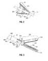
- FIG. 4Ais a side view of the shaft of the forceps of FIG. 1 shown with parts separated;
- FIG. 4Bis a side view of the shaft of the forceps of FIG. 1 in an assembled condition.
- Forceps 10configured for use in connection with endoscopic surgical procedures is shown.
- Forceps 10is one example of a shaft-based surgical instrument incorporating the features of the present disclosure.
- the presently disclosed features detailed beloware equally applicable to other shaft-based surgical instruments and are described with reference to forceps 10 for exemplary purposes only.
- different electrical and mechanical connections and considerationsmay apply to each particular type of instrument; however, the novel aspects of the present disclosure remain generally consistent with respect to most shaft-based surgical instruments.
- forceps 10defines a longitudinal axis “X-X” and includes a housing 20 , a handle assembly 30 , a rotating assembly 70 , a trigger assembly 80 and an end effector assembly 100 .
- Forceps 10further includes a shaft 12 having a distal end 14 configured to mechanically engage end effector assembly 100 and a proximal end 16 that extends into housing 20 and is mechanically engaged to distal cone 22 of housing 20 (see FIG. 2 ).
- Forceps 10also includes electrosurgical cable 610 that connects forceps 10 to a generator (not shown) or other suitable power source, although forceps 10 may alternatively be configured as a battery powered instrument.
- Cable 610includes a wire (or wires) (not shown) extending therethrough that has sufficient length to extend through shaft 12 in order to provide electrical energy to the end effector assembly 100 , e.g., upon activation of activation switch 90 .
- handle assembly 30includes fixed handle 50 and a moveable handle 40 .
- Fixed handle 50is integrally associated with housing 20 and handle 40 is moveable relative to fixed handle 50 .
- Rotating assembly 70includes a rotatable wheel 72 that is rotatable in either direction about longitudinal axis “X-X” to rotate end effector assembly 100 about longitudinal axis “X-X.”
- Housing 20houses the internal working components of forceps 10 .
- End effector assembly 100is shown attached at a distal end 14 of shaft 12 and includes a pair of opposing jaw members 110 and 120 .
- Each of the jaw members 110 and 120includes an opposed electrically conductive tissue-sealing plate 112 , 122 , respectively.
- End effector assembly 100is designed as a unilateral assembly, i.e., where jaw member 120 is fixed relative to shaft 12 and jaw member 110 is moveable about pivot 103 relative to shaft 12 and fixed jaw member 120 .
- end effector assembly 100may alternatively be configured as a bilateral assembly, i.e., where both jaw member 110 and jaw member 120 are moveable about pivot 103 relative to one another and to shaft 12 .
- a knife assembly(not shown) is disposed within shaft 12 and a knife channel 125 ( FIG. 3 ) is defined within one or both of the jaw members 110 , 120 , to permit reciprocation of a knife blade (not shown) therethrough, e.g., via activation of a trigger 82 of trigger assembly 80 .
- moveable handle 40 of handle assembly 30is ultimately connected to a drive assembly (not shown) that, together, mechanically cooperate to impart movement of jaw members 110 and 120 between a spaced-apart position and an approximated position to grasp tissue disposed between sealing plates 112 and 122 of jaw members 110 , 120 , respectively.
- moveable handle 40is initially spaced-apart from fixed handle 50 and, correspondingly, jaw members 110 , 120 are disposed in the spaced-apart position.
- Moveable handle 40is actuatable from this initial position to a depressed position corresponding to the approximated position of jaw members 110 , 120 .
- shaft 12 of forceps 10is shown.
- Shaft 12defines a generally cylindrically-shaped configuration, although other configurations are contemplated, and may be formed from any suitable biocompatible material. More particularly, shaft 12 is formed from three different segments: a proximal segment 200 , a distal segment 300 , and an elongated intermediate segment 400 that extends between and couples the proximal and distal segments 200 , 300 , respectively, to one another. However, greater or fewer than three segments may be provided, depending on the configuration of the particular surgical instrument incorporating shaft 12 .
- shaft 12is shown including specifically-configured proximal and distal segments 200 , 300 , respectively, for engagement with housing 20 and end effector assembly 100 , respectively, of forceps 10 ( FIG. 1 ), shaft 12 may include various different segments of different configurations adapted to secure shaft 12 to the end effector assembly and housing, or handle assembly of any other suitable surgical instrument.
- proximal and distal segments 200 , 300respectively, detailed below are only exemplary.
- Proximal segment 200 of shaft 12extends proximally from proximal end 402 of intermediate segment 400 ( FIGS. 4A-4B ) into distal cone 22 of housing 20 ( FIG. 1 ). More specifically, proximal segment 200 of shaft 12 extends through first and second retaining discs 23 , 24 , respectively, disposed within distal cone 22 of housing 20 ( FIG. 1 ). Proximal segment 200 further includes a pair of tabs 210 extending radially-outwardly therefrom that are disposed between first and second retaining discs 23 , 24 , respectively, to engage shaft 12 within distal cone 22 of housing 20 ( FIG.
- Proximal segment 200 and tabs 210 extending therefrommay be monolithically formed as a single component, e.g., via stamping. Stamping is a relatively inexpensive process and is advantageous in that specific features, e.g., tabs 210 , mounting flanges 320 ( FIG. 3-4B ), apertures 322 ( FIG. 3-4B ), cam slots 324 ( FIG. 3-4B ), etc., may be subsequently or simultaneously formed through the stamped components, as desired.
- Distal segment 300 of shaft 12extends distally from distal end 404 of intermediate segment 400 ( FIGS. 4A-4B ) and includes a clevis 310 .
- Clevis 310 of distal segment 300includes a pair of mounting flanges 320 that are formed with distal segment 300 of shaft 12 and extend therefrom in spaced-relation relative to one another.
- Each of the mounting flanges 320includes an aperture 322 defined therethrough that is configured to receive pivot pin 103 ( FIG. 1 ) therethrough to pivotably mount jaw members 110 , 120 between mounting flanges 320 .
- mounting flanges 320are configured to be positioned on either side of jaw members 110 , 120 such that pivot pin 103 may inserted through aperture 322 of one of mounting flanges 320 , through apertures (not explicitly shown) defined within each of jaw members 110 , 120 , and through aperture 322 defined within the other mounting flange 320 to pivotably engage jaw members 110 , 120 of end effector assembly 100 to mounting flanges 320 of clevis 310 of distal segment 300 of shaft 12 .
- jaw member 120may be fixedly engaged to one or both of mounting flanges 320 , while jaw member 110 is pivotably moveable relative thereto between the spaced-apart and approximated positions.
- both of jaw members 110 , 120are pivotably coupled to mounting flanges 320 .
- Mounting flanges 320 of clevis 310 of distal segment 300 of shaft 12each further include a cam slot 324 defined therethrough.
- Cam slots 324are configured to receive drive pin 326 therethrough.
- Drive pin 326extends from the drive bar (not shown) of the drive assembly (not shown) and is disposed within cam slots 324 of mounting flanges 324 as well as a cam slot (not shown) defined within jaw member 110 (and/or jaw member 120 ).
- the drive bar (not shown) of the drive assemblyis selectively translatable through shaft 12 and relative to end effector assembly 100 e.g., upon actuation of moveable handle 40 of handle assembly 30 , to translate drive pin 326 along cam slots 324 and along the cam slot (not shown) defined within jaw member 110 (and/or jaw member 120 ) to urge jaw member 110 to pivot about pivot pin 103 relative to jaw member 120 between the spaced-apart position and the approximated position to grasp tissue therebetween.
- Distal segment 300 of shaft 12including mounting flanges 320 of clevis 310 , and apertures 322 and cam slots 324 thereof, may be monolithically formed as a single component via stamping or any other suitable process.
- Intermediate segment 400 of shaft 12defines a cylindrically-shaped configuration and has a length sufficient for insertion of end effector assembly 100 of forceps 10 into an internal surgical site, while housing 20 of forceps 10 remains disposed externally of the surgical site.
- Intermediate segment 400may be a drawn tube cut to a pre-determined length, or may be formed via any other suitable process.
- intermediate segment 400is simply a cylindrical tube and does not include any of the complex features of proximal segment 200 , e.g., tabs 210 , or distal segment 300 , e.g., clevis 310 and the components and features thereof, intermediate segment 400 may be formed, for example, by tube-drawing and may then be cut to a pre-determined length, i.e., a desired length.
- Tube-drawingis advantageous in that it is a relatively inexpensive, simple, and precise method of forming a shaft with a smooth surface finish and precise, consistent dimensions. Such features facilitate the insertion of shaft 12 into and the removal of shaft 12 from the internal surgical site.
- proximal and distal segments 200 , 300 , respectively, of shaft 12facilitate the use and operation of forceps 10 .
- jaw members 110 , 120 of end effector assembly 100are initially disposed in the spaced-apart position. In this position, as mentioned above, moveable handle 40 is disposed in the initial, spaced-apart position relative to fixed handle 50 .
- end effector assembly 100is maneuvered into position, e.g., inserted into the internal surgical site, such that tissue to be grasped, sealed, and/or divided, is disposed between jaw members 110 , 120 .
- Wheel 72 of rotation assembly 70may be rotated to rotate shaft 12 about longitudinal axis “X-X” to thereby rotate end effector assembly 100 about longitudinal axis “X-X” to better position jaw members 110 , 120 such that tissue is disposed therebetween.
- shaft 12is permitted to rotate to position end effector assembly 100 as desired, shaft 12 is retained in fixed longitudinal position relative to housing 20 via the engagement of tabs 210 of proximal segment 200 of shaft 12 between retaining discs 23 , 24 of distal cone 22 of housing 20 .
- moveable handle 40is pulled proximally relative to fixed handle 50 such that jaw member 110 is pivoted relative to jaw member 120 from the spaced-apart position to the approximated position to grasp tissue therebetween. More specifically, as moveable handle 40 is pulled proximally, the drive bar (not shown) is translated through shaft 12 and relative to end effector assembly 100 to translate drive pin 326 through cam slots 324 of mounting flanges 320 and through the cam slot (not shown) defined within jaw member 110 to urge jaw member 110 to rotate about pivot 103 from the spaced-apart position to the approximated position. Thereafter, electrosurgical energy may be supplied, e.g., via activation of switch 90 ( FIG.
- tissue-sealing plate 112 and/or tissue-sealing plate 122may then be advanced between jaw members 110 , 120 , e.g., via activation of trigger 82 of trigger assembly 80 , to cut the previously treated tissue grasped between jaw members 110 , 120 (or to cut untreated tissue, depending on a particular purpose).
- moveable handle 40may be returned to the initial position, translating the drive bar (not shown) back through shaft 12 and relative to end effector assembly 100 such that jaw member 110 is urged to pivot back to the spaced-apart position.
- proximal segment 200proximal segment 200
- distal segment 300distal segment 400
- intermediate segment 400may be formed from tube-drawing and may then be cut to a desired length.
- proximal, distal, and intermediate segments 200 , 300 , 400may be assembled together to form shaft 12 . More specifically, proximal and distal segments 200 , 300 , respectively, are welded, e.g., laser-welded or spin-welded (i.e., friction-welded), to the respective proximal and distal ends 402 , 404 of intermediate segment 400 .
- Laser-weldinginvolves applying a continuous or pulsed laser beam to the abutting ends of the segments to be joined, e.g., the distal end of proximal segment 200 and proximal end 420 of intermediate segment 400 , or the proximal end of distal segment 300 and distal end 404 of intermediate segment 400 , to heat and weld the segments to one another.
- the proximal and distal segments 200 , 300may be retained in fixed orientation relative to intermediate segment 400 , e.g., in a suitable holder (not shown), during welding.
- the segment(s)are rotated relative to one another at a sufficiently high speed such that the friction generated therebetween heats the abutting ends of the segments to the welding point, or welding temperature, i.e., such that the abutting ends of the segments are heated to a molten or semi-molten state.
- welding pointor welding temperature, i.e., such that the abutting ends of the segments are heated to a molten or semi-molten state.
- the welded joint formed upon urging of the molten or semi-molten ends of the segments to one anothere.g., welded joint 403 formed between proximal segment 200 and proximal end 402 of intermediate segment 400 or welded joint 405 formed between distal segment 300 and distal end 404 of intermediate segment 400 , is permitted to cool and solidify, thereby fixedly joining the segments to one another.
- welded joints 403 , 405may be machined, or cut down such that welded joints 403 , 405 are flush with the outer periphery of shaft 12 .
- the inertia of the spinning forces during the spin-welding processinhibit welded joints 403 , 405 from protruding inwardly into formed shaft 12 and, thus, the inner surface of welded joints 403 , 405 need not be cut, or otherwise altered.
- Proximal and distal segments 200 , 300 , respectively, of shaft 12may be spin-welded to intermediate segment 400 of shaft 12 simultaneously with one another, or separately from one another, i.e., consecutively.
- the deceleration of the segment and the orientation of the segment once fully stoppedmay be controlled to facilitate precise alignment of proximal and distal segments 200 , 300 , respectively, relative to one another upon formation of shaft 12 .
- the proximal and distal segments 200 , 300 , respectively,are clocked to one another to ensure proper alignment therebetween.
- intermediate segment 400may be held stationary, while proximal and distal segments 200 , 300 , respectively, are rotated relative to intermediate segment 400 in abutting relation therewith at proximal and distal ends 402 , 404 , respectively, thereof.
- the rotating assemblies(not shown) configured to rotate proximal and distal segments 200 , 300 , respectively, relative to intermediate segment 400 during simultaneous spin-welding thereto may be mechanically and/or electrically coupled to one another to ensure adequate formation of both welded joints 403 , 405 by ensuring that proximal and distal segments 200 , 300 , respectively, are rotated at substantially the same clock rate and that the spin-welding processes for welding proximal segment 200 to proximal end 402 of intermediate segment 400 and distal segment 300 to distal end 404 of intermediate segment are completed in substantially the same time.
- ensuring that both the proximal and distal segments 200 , 300 , respectively, spin at the same clock rate and are decelerated and stopped in substantially the same timei.e., ensuring that the proximal and distal segments 200 , 300 , respectively, are clocked to one another, allows precise alignment between the proximal and distal segments 200 , 300 , respectively, and the relative features associated with each segment, e.g., tabs 210 , cam slots 324 , clevis 310 , etc.
- the resulting shaft 12includes proximal segment 200 welded to intermediate segment 400 at proximal end 402 thereof via first weld joint 403 and distal segment 300 welded to intermediate segment 400 at distal end 404 thereof via second weld join 405 , thus forming a single, continuous shaft 12 .
- Forming the three segments of shaft 12e.g., proximal segment 200 , distal segment 300 and intermediate segment 400 , independently of one another and then joining the segments 200 , 300 , 400 to one another provides a simplified, customizable process for manufacturing shafts 12 .
- proximal and distal segments 200 , 300may be stamped (or otherwise formed) to include the required features for operably engaging shaft 12 to housing 20 and end effector assembly 100 , respectively, (or, more generally, for engaging shaft 12 to any other components of the surgical instrument to be used in conjunction therewith) depending upon the specific configuration of housing 20 and end effector assembly 100 , respectively.
- Intermediate segment 400may be cut to a specific length as required for the particular surgical instrument to be used with shaft 12 .
- proximal segment 200is welded (or otherwise formed) to proximal end 402 of intermediate segment 400 and distal segment 300 is welded (or otherwise formed) to distal end 404 of intermediate segment 400 , ensuring that the specific components of proximal and distal segments 200 , 300 , respectively, are aligned with one another.
- the presently disclosed manufacturing processpermits each of the segments 200 , 300 , 400 of shaft 12 to be independently formed and customized for a particular purpose, and then aligned later, e.g., during welding of the segments 200 , 300 , 400 to one another.
- shaft 12may be secured within housing 20 at proximal end 16 thereof and may engage end effector assembly 100 thereon at distal end 14 thereof, for use in conjunction with forceps 10 , as described above.
Landscapes
- Engineering & Computer Science (AREA)
- Health & Medical Sciences (AREA)
- Mechanical Engineering (AREA)
- Physics & Mathematics (AREA)
- Surgery (AREA)
- Life Sciences & Earth Sciences (AREA)
- Optics & Photonics (AREA)
- Plasma & Fusion (AREA)
- Biomedical Technology (AREA)
- Nuclear Medicine, Radiotherapy & Molecular Imaging (AREA)
- Heart & Thoracic Surgery (AREA)
- Medical Informatics (AREA)
- Molecular Biology (AREA)
- Animal Behavior & Ethology (AREA)
- General Health & Medical Sciences (AREA)
- Public Health (AREA)
- Veterinary Medicine (AREA)
- Otolaryngology (AREA)
- Ophthalmology & Optometry (AREA)
- Surgical Instruments (AREA)
Abstract
Description
The present disclosure relates to surgical instruments and, more particularly, to surgical forceps for grasping, sealing, and/or dividing tissue.
A forceps is a plier-like instrument which relies on mechanical action between its jaws to grasp, clamp and constrict vessels or tissue. Electrosurgical forceps utilize both mechanical clamping action and electrical energy to affect hemostasis by heating tissue and blood vessels to coagulate and/or cauterize tissue. Certain surgical procedures require more than simply cauterizing tissue and rely on the unique combination of clamping pressure, precise electrosurgical energy control and gap distance (i.e., distance between opposing jaw members when closed about tissue) to “seal” tissue, vessels and certain vascular bundles. Typically, once a vessel is sealed, the surgeon has to accurately sever the vessel along the newly formed tissue seal. Accordingly, many vessel sealing instruments have been designed which incorporate a knife or blade member that effectively severs the tissue after forming a tissue seal.
An endoscopic surgical forceps typically includes an elongated shaft having an end effector assembly, e.g., a pair of jaw members, disposed at the distal end thereof. The elongated shaft permits the surgeon to insert the end effector assembly through a relatively small access opening in the body to the internal surgical site, while the housing of the endoscopic forceps remains disposed externally of the surgical site. The surgeon may then control the operation of the end effector assembly, e.g., to grasp, seal, and/or divide tissue, by manipulating the housing.
As can be appreciated, the shafts of surgical instruments typically include numerous mechanical features at the ends thereof to facilitate operative engagement of the end effector assembly to the shaft at one end thereof and the housing, or handle assembly at the other end thereof such that the surgeon may operate the end effector assembly by manipulating mechanical components coupled to the housing.
As used herein, the term “distal” refers to the portion that is being described which is further from a user, while the term “proximal” refers to the portion that is being described which is closer to a user.
Any or all of the aspects described herein, to the extent they are consistent, may be used in conjunction with any of the other aspects described herein.
A method of manufacturing a shaft of a surgical instrument is provided in accordance with the present disclosure. The method includes forming a proximal segment of the shaft to include one or more features for operably engaging the shaft to a first component of the surgical instrument, forming a distal segment of the shaft to include one or more features for operably engaging the shaft to a second component of the surgical instrument, and forming an intermediate segment of the shaft. The proximal segment of the shaft is welded to a proximal end of the intermediate segment and the distal end of the shaft is welded to a distal end of the intermediate segment. The welding of the proximal segment and/or the distal segment to the intermediate segment is configured such that the feature(s) of each of the proximal and distal segments are aligned in a pre-determined orientation relative to one another.
In one aspect, the proximal segment and/or the distal segment are welded to the intermediate segment via laser welding. Alternatively, the proximal segment and/or the distal segment may be welded to the intermediate segment via spin-welding, or one of the proximal and distal segments may be welded via laser welding, while the other is welded via spin-welding.
In another aspect, the welding of the proximal segment and the welding of the distal segment to the proximal and distal ends of the intermediate segment, respectively, are performed simultaneously and are clocked to one another to ensure alignment of the proximal segment and the distal segment in the pre-determined orientation relative to one another.
In yet another aspect, the intermediate segment is formed via tube-drawing. Further, the formed intermediate segment may be cut to a pre-determined length prior to welding of the proximal and distal segments thereto.
Another method of manufacturing a shaft of a surgical instrument is also provided in accordance with the present disclosure. The method includes forming a proximal segment of the shaft, forming a distal segment of the shaft, forming an intermediate segment of the shaft, and spin-welding the proximal segment of the shaft to a proximal end of the intermediate segment and the distal segment of the shaft to a distal end of the intermediate segment. The proximal and distal segments are clocked to one another during spin-welding to ensure alignment of the proximal and distal segments in a pre-determined orientation relative to one another.
In one aspect, the proximal segment and/or the distal segment are formed to include one or more features for operably engaging the shaft to the surgical instrument. The proximal and distal segments may be clocked to one another during spin-welding to ensure proper alignment of the feature(s) of each of the proximal and distal segments in the pre-determined orientation relative to one another.
In another aspect, the proximal and distal segments are simultaneously spin-welded to the intermediate segment.
In yet another aspect, the proximal segment and/or the distal segment are formed via stamping. The intermediate segment, on the other hand, may be formed via tube-drawing and/or may be cut to a pre-determined length prior to welding of the proximal and distal segments thereto.
In accordance with the present disclosure, another method of manufacturing a shaft of a surgical instrument is provided. The method includes stamping a proximal segment of the shaft to include one or more features for operably engaging the shaft to a first component of the surgical instrument, stamping a distal segment of the shaft to include one or more features for operably engaging the shaft to a second component of the surgical instrument, forming an intermediate segment of the shaft, cutting the intermediate segment to a pre-determined length, welding the proximal segment of the shaft to a proximal end of the intermediate segment, and welding the distal segment of the shaft to a distal end of the intermediate segment.
The proximal segment and the distal segment may be welded to the intermediate segment via laser welding, spin-welding, or any other suitable welding method. The intermediate segment, on the other hand, may be formed via tube-drawing.
In another aspect, welding of the proximal segment and/or the distal segment to the intermediate segment is configured such that the feature(s) of each of the proximal and distal segments are aligned in a pre-determined orientation relative to one another.
Various aspects of the present disclosure are described herein with reference to the drawings wherein like reference numerals identify similar or identical elements:
Referring now toFIG. 1 , aforceps 10 configured for use in connection with endoscopic surgical procedures is shown.Forceps 10 is one example of a shaft-based surgical instrument incorporating the features of the present disclosure. As can be appreciated, the presently disclosed features detailed below are equally applicable to other shaft-based surgical instruments and are described with reference to forceps10 for exemplary purposes only. Obviously, different electrical and mechanical connections and considerations may apply to each particular type of instrument; however, the novel aspects of the present disclosure remain generally consistent with respect to most shaft-based surgical instruments.
With continued reference toFIG. 1 ,forceps 10 defines a longitudinal axis “X-X” and includes ahousing 20, ahandle assembly 30, arotating assembly 70, atrigger assembly 80 and anend effector assembly 100.Forceps 10 further includes ashaft 12 having adistal end 14 configured to mechanically engageend effector assembly 100 and aproximal end 16 that extends intohousing 20 and is mechanically engaged to distalcone 22 of housing20 (seeFIG. 2 ).Forceps 10 also includeselectrosurgical cable 610 that connectsforceps 10 to a generator (not shown) or other suitable power source, althoughforceps 10 may alternatively be configured as a battery powered instrument.Cable 610 includes a wire (or wires) (not shown) extending therethrough that has sufficient length to extend throughshaft 12 in order to provide electrical energy to theend effector assembly 100, e.g., upon activation ofactivation switch 90.
Continuing with reference toFIG. 1 ,handle assembly 30 includesfixed handle 50 and amoveable handle 40. Fixedhandle 50 is integrally associated withhousing 20 andhandle 40 is moveable relative tofixed handle 50.Rotating assembly 70 includes arotatable wheel 72 that is rotatable in either direction about longitudinal axis “X-X” to rotateend effector assembly 100 about longitudinal axis “X-X.”Housing 20 houses the internal working components offorceps 10.
Referring still toFIG. 1 ,moveable handle 40 ofhandle assembly 30 is ultimately connected to a drive assembly (not shown) that, together, mechanically cooperate to impart movement ofjaw members sealing plates jaw members FIG. 1 ,moveable handle 40 is initially spaced-apart from fixedhandle 50 and, correspondingly,jaw members Moveable handle 40 is actuatable from this initial position to a depressed position corresponding to the approximated position ofjaw members
With reference toFIGS. 2-4B ,shaft 12 offorceps 10 is shown.Shaft 12 defines a generally cylindrically-shaped configuration, although other configurations are contemplated, and may be formed from any suitable biocompatible material. More particularly,shaft 12 is formed from three different segments: aproximal segment 200, adistal segment 300, and an elongatedintermediate segment 400 that extends between and couples the proximal anddistal segments instrument incorporating shaft 12. In other words, althoughshaft 12 is shown including specifically-configured proximal anddistal segments housing 20 andend effector assembly 100, respectively, of forceps10 (FIG. 1 ),shaft 12 may include various different segments of different configurations adapted to secureshaft 12 to the end effector assembly and housing, or handle assembly of any other suitable surgical instrument. As such, the particular features of proximal anddistal segments
In embodiments whereend effector assembly 100 is designed as a unilateral assembly, e.g., as shown inFIGS. 1 and 3 ,jaw member 120 may be fixedly engaged to one or both of mountingflanges 320, whilejaw member 110 is pivotably moveable relative thereto between the spaced-apart and approximated positions. On the other hand, in bilateral embodiments, both ofjaw members flanges 320.
Mountingflanges 320 ofclevis 310 ofdistal segment 300 ofshaft 12 each further include acam slot 324 defined therethrough.Cam slots 324 are configured to receivedrive pin 326 therethrough.Drive pin 326 extends from the drive bar (not shown) of the drive assembly (not shown) and is disposed withincam slots 324 of mountingflanges 324 as well as a cam slot (not shown) defined within jaw member110 (and/or jaw member120). The drive bar (not shown) of the drive assembly (not shown), is selectively translatable throughshaft 12 and relative to endeffector assembly 100 e.g., upon actuation ofmoveable handle 40 ofhandle assembly 30, to translatedrive pin 326 alongcam slots 324 and along the cam slot (not shown) defined within jaw member110 (and/or jaw member120) to urgejaw member 110 to pivot aboutpivot pin 103 relative tojaw member 120 between the spaced-apart position and the approximated position to grasp tissue therebetween.Distal segment 300 ofshaft 12, including mountingflanges 320 ofclevis 310, andapertures 322 andcam slots 324 thereof, may be monolithically formed as a single component via stamping or any other suitable process.
Referring now toFIGS. 1-3 , the use and operation offorceps 10 will be briefly described. As will become apparent in view of the following, the specific features of proximal anddistal segments shaft 12 facilitate the use and operation offorceps 10. As shown inFIG. 1 ,jaw members end effector assembly 100 are initially disposed in the spaced-apart position. In this position, as mentioned above,moveable handle 40 is disposed in the initial, spaced-apart position relative to fixedhandle 50.
In use,end effector assembly 100 is maneuvered into position, e.g., inserted into the internal surgical site, such that tissue to be grasped, sealed, and/or divided, is disposed betweenjaw members Wheel 72 ofrotation assembly 70 may be rotated to rotateshaft 12 about longitudinal axis “X-X” to thereby rotateend effector assembly 100 about longitudinal axis “X-X” to betterposition jaw members shaft 12 is permitted to rotate to positionend effector assembly 100 as desired,shaft 12 is retained in fixed longitudinal position relative tohousing 20 via the engagement oftabs 210 ofproximal segment 200 ofshaft 12 between retainingdiscs distal cone 22 ofhousing 20.
Next,moveable handle 40 is pulled proximally relative to fixedhandle 50 such thatjaw member 110 is pivoted relative tojaw member 120 from the spaced-apart position to the approximated position to grasp tissue therebetween. More specifically, asmoveable handle 40 is pulled proximally, the drive bar (not shown) is translated throughshaft 12 and relative to endeffector assembly 100 to translatedrive pin 326 throughcam slots 324 of mountingflanges 320 and through the cam slot (not shown) defined withinjaw member 110 to urgejaw member 110 to rotate aboutpivot 103 from the spaced-apart position to the approximated position. Thereafter, electrosurgical energy may be supplied, e.g., via activation of switch90 (FIG. 1 ), to tissue-sealingplate 112 and/or tissue-sealingplate 122 and conducted through tissue to effect a tissue seal, or otherwise treat tissue. As mentioned above, a knife blade (not shown) may then be advanced betweenjaw members trigger 82 oftrigger assembly 80, to cut the previously treated tissue grasped betweenjaw members 110,120 (or to cut untreated tissue, depending on a particular purpose). Finally,moveable handle 40 may be returned to the initial position, translating the drive bar (not shown) back throughshaft 12 and relative to endeffector assembly 100 such thatjaw member 110 is urged to pivot back to the spaced-apart position.
With reference now toFIGS. 1-4B , the manufacture ofshaft 12 for use withforceps 10 is described, keeping in mind thatshaft 12 may similarly be manufactured to incorporate other features for use with other surgical instruments. Initially, each of the components ofshaft 12, i.e.,proximal segment 200,distal segment 300, andintermediate segment 400, are independently formed. More specifically, as mentioned above, proximal anddistal segments housing 20 andend effector assembly 100, respectively.Intermediate segment 400, on the other hand, may be formed from tube-drawing and may then be cut to a desired length.
Once the proximal, distal, andintermediate segments shaft 12. More specifically, proximal anddistal segments distal ends intermediate segment 400. Laser-welding involves applying a continuous or pulsed laser beam to the abutting ends of the segments to be joined, e.g., the distal end ofproximal segment 200 and proximal end420 ofintermediate segment 400, or the proximal end ofdistal segment 300 anddistal end 404 ofintermediate segment 400, to heat and weld the segments to one another. Further, where precise alignment of the proximal anddistal segments tabs 210,cam slots 324,clevis 310, is required, the proximal anddistal segments intermediate segment 400, e.g., in a suitable holder (not shown), during welding.
Spin-welding, or friction-welding involves positioning the segments to be welded to one another in abutting relation relative to one another, e.g., positioningproximal segment 200 in abutting relation withproximal end 402 ofintermediate segment 400 and/or positioningdistal segment 300 in abutting relation withdistal end 404 ofintermediate segment 400, and rotating one or both of the segments relative to the other at a high rate of speed to generate friction therebetween. The segment(s) are rotated relative to one another at a sufficiently high speed such that the friction generated therebetween heats the abutting ends of the segments to the welding point, or welding temperature, i.e., such that the abutting ends of the segments are heated to a molten or semi-molten state. Once this welding point has been reached, the segments are urged toward one another and the rotating segment(s) is rapidly decelerated until the rotation is fully stopped. With the abutting ends of the segments no longer rotating relative to one another to create friction therebetween, the welded joint formed upon urging of the molten or semi-molten ends of the segments to one another, e.g., welded joint403 formed betweenproximal segment 200 andproximal end 402 ofintermediate segment 400 or welded joint405 formed betweendistal segment 300 anddistal end 404 ofintermediate segment 400, is permitted to cool and solidify, thereby fixedly joining the segments to one another.
Once the welded joints, e.g., weldedjoints joints joints shaft 12. The inertia of the spinning forces during the spin-welding process inhibit weldedjoints shaft 12 and, thus, the inner surface of weldedjoints
Proximal anddistal segments shaft 12 may be spin-welded tointermediate segment 400 ofshaft 12 simultaneously with one another, or separately from one another, i.e., consecutively. To weld proximal anddistal segments proximal segment 200, is rotated whileintermediate segment 400 is held in fixed position to create weld joint403 therebetween. Thereafter, the other segment, e.g.,distal segment 300, is rotated relative tointermediate segment 400 andproximal segment 200 welded thereto, to create weld joint405 therebetween, thus forming the completedshaft 12. When welding the other segment to intermediate segment400 (after the initial segment has been welded to intermediate segment400), the deceleration of the segment and the orientation of the segment once fully stopped may be controlled to facilitate precise alignment of proximal anddistal segments shaft 12. In other words, the proximal anddistal segments
With regard to simultaneous spin-welding ofshaft 12,intermediate segment 400 may be held stationary, while proximal anddistal segments intermediate segment 400 in abutting relation therewith at proximal anddistal ends distal segments intermediate segment 400 during simultaneous spin-welding thereto may be mechanically and/or electrically coupled to one another to ensure adequate formation of both weldedjoints distal segments proximal segment 200 toproximal end 402 ofintermediate segment 400 anddistal segment 300 todistal end 404 of intermediate segment are completed in substantially the same time. In addition, and if applicable to the particular shaft being assembled, ensuring that both the proximal anddistal segments distal segments distal segments tabs 210,cam slots 324,clevis 310, etc.
In either welding process, the resultingshaft 12 includesproximal segment 200 welded tointermediate segment 400 atproximal end 402 thereof via first weld joint403 anddistal segment 300 welded tointermediate segment 400 atdistal end 404 thereof via second weld join405, thus forming a single,continuous shaft 12. Forming the three segments ofshaft 12, e.g.,proximal segment 200,distal segment 300 andintermediate segment 400, independently of one another and then joining thesegments shafts 12. More specifically, proximal anddistal segments shaft 12 tohousing 20 andend effector assembly 100, respectively, (or, more generally, for engagingshaft 12 to any other components of the surgical instrument to be used in conjunction therewith) depending upon the specific configuration ofhousing 20 andend effector assembly 100, respectively.Intermediate segment 400, on the other hand, may be cut to a specific length as required for the particular surgical instrument to be used withshaft 12. Once the threesegments proximal segment 200 is welded (or otherwise formed) toproximal end 402 ofintermediate segment 400 anddistal segment 300 is welded (or otherwise formed) todistal end 404 ofintermediate segment 400, ensuring that the specific components of proximal anddistal segments segments shaft 12 to be independently formed and customized for a particular purpose, and then aligned later, e.g., during welding of thesegments entire shaft 12 as a single segment while also ensuring that the different features and/or components of the proximal and distal ends are properly aligned with one another during formation ofshaft 12. Ultimately,shaft 12 may be secured withinhousing 20 atproximal end 16 thereof and may engageend effector assembly 100 thereon atdistal end 14 thereof, for use in conjunction withforceps 10, as described above.
From the foregoing and with reference to the various figure drawings, those skilled in the art will appreciate that certain modifications can also be made to the present disclosure without departing from the scope of the same. While several embodiments of the disclosure have been shown in the drawings, it is not intended that the disclosure be limited thereto, as it is intended that the disclosure be as broad in scope as the art will allow and that the specification be read likewise. Therefore, the above description should not be construed as limiting, but merely as exemplifications of particular embodiments. Those skilled in the art will envision other modifications within the scope and spirit of the claims appended hereto.
Claims (19)
1. A method of manufacturing a shaft of a surgical instrument, comprising:
forming a proximal segment of the shaft to include at least one feature for operably engaging the shaft to a first component of the surgical instrument;
forming a distal segment of the shaft to include at least one feature for operably engaging the shaft to a second component of the surgical instrument;
forming an intermediate segment of the shaft;
welding the proximal segment of the shaft to a proximal end of the intermediate segment; and
welding the distal segment of the shaft to a distal end of the intermediate segment, wherein the welding of at least one of the proximal segment and the distal segment to the intermediate segment is configured such that the at least one feature of the proximal and distal segments are aligned in a pre-determined orientation relative to one another.
2. The method according toclaim 1 , wherein at least one of the proximal segment and the distal segment is welded to the intermediate segment via laser welding.
3. The method according toclaim 1 , wherein at least one of the proximal segment and the distal segment is welded to the intermediate segment via spin-welding.
4. The method according toclaim 1 , wherein the steps of welding the proximal segment of the shaft to a proximal end of the intermediate segment and welding the distal segment of the shaft to a distal end of the intermediate segment are performed simultaneously and are clocked to one another to ensure alignment of the proximal segment and the distal segment in the pre-determined orientation relative to one another.
5. The method according toclaim 1 , wherein the intermediate segment is formed via tube-drawing.
6. The method according toclaim 1 , wherein the formed intermediate segment is cut to a pre-determined length prior to welding of the proximal and distal segments thereto.
7. A method of manufacturing a shaft of a surgical instrument, comprising:
forming a proximal segment of the shaft;
forming a distal segment of the shaft;
forming an intermediate segment of the shaft;
spin-welding the proximal segment of the shaft to a proximal end of the intermediate segment and the distal segment of the shaft to a distal end of the intermediate segment, the proximal and distal segments clocked to one another during spin-welding to ensure alignment of the proximal and distal segments in a pre-determined orientation relative to one another.
8. The method according toclaim 7 , wherein at least one of the proximal segment and the distal segment are formed to include at least one feature for operably engaging the shaft to the surgical instrument.
9. The method according toclaim 8 , wherein the proximal segment of the shaft is formed to include at least one feature for operably engaging the shaft to a first component of the surgical instrument, and wherein the distal segment of the shaft is formed to include at least one feature for operably engaging the shaft to a second component of the surgical instrument.
10. The method according toclaim 9 , wherein the proximal and distal segments are clocked to one another during spin-welding to ensure proper alignment of the at least one feature of the proximal segment and the at least one feature of the distal segment in the pre-determined orientation relative to one another.
11. The method according toclaim 7 , wherein the proximal and distal segments are simultaneously spin-welded to the intermediate segment.
12. The method according toclaim 7 , wherein at least one of the proximal and distal segments is formed via stamping.
13. The method according toclaim 7 , wherein the intermediate segment is formed via tube-drawing.
14. The method according toclaim 7 , wherein the formed intermediate segment is cut to a pre-determined length prior to welding of the proximal and distal segments thereto.
15. A method of manufacturing a shaft of a surgical instrument, comprising:
stamping a proximal segment of the shaft to include at least one feature for operably engaging the shaft to a first component of the surgical instrument;
stamping a distal segment of the shaft to include at least one feature for operably engaging the shaft to a second component of the surgical instrument;
forming an intermediate segment of the shaft;
cutting the intermediate segment to a pre-determined length;
welding the proximal segment of the shaft to a proximal end of the intermediate segment; and
welding the distal segment of the shaft to a distal end of the intermediate segment.
16. The method according toclaim 15 , wherein at least one of the proximal segment and the distal segment is welded to the intermediate segment via laser welding.
17. The method according toclaim 15 , wherein at least one of the proximal segment and the distal segment is welded to the intermediate segment via spin-welding.
18. The method according toclaim 15 , wherein the welding of at least one of the proximal segment and the distal segment to the intermediate segment is configured such that the at least one feature of each of the proximal and distal segments are aligned in a pre-determined orientation relative to one another.
19. The method according toclaim 15 , wherein the intermediate segment is formed via tube-drawing.
Priority Applications (2)
| Application Number | Priority Date | Filing Date | Title |
|---|---|---|---|
| US13/248,976US8756785B2 (en) | 2011-09-29 | 2011-09-29 | Surgical instrument shafts and methods of manufacturing shafts for surgical instruments |
| US14/297,404US9795402B2 (en) | 2011-09-29 | 2014-06-05 | Surgical instrument shafts and methods of manufacturing shafts for surgical instruments |
Applications Claiming Priority (1)
| Application Number | Priority Date | Filing Date | Title |
|---|---|---|---|
| US13/248,976US8756785B2 (en) | 2011-09-29 | 2011-09-29 | Surgical instrument shafts and methods of manufacturing shafts for surgical instruments |
Related Child Applications (1)
| Application Number | Title | Priority Date | Filing Date |
|---|---|---|---|
| US14/297,404ContinuationUS9795402B2 (en) | 2011-09-29 | 2014-06-05 | Surgical instrument shafts and methods of manufacturing shafts for surgical instruments |
Publications (2)
| Publication Number | Publication Date |
|---|---|
| US20130082035A1 US20130082035A1 (en) | 2013-04-04 |
| US8756785B2true US8756785B2 (en) | 2014-06-24 |
Family
ID=47991630
Family Applications (2)
| Application Number | Title | Priority Date | Filing Date |
|---|---|---|---|
| US13/248,976Active2032-12-12US8756785B2 (en) | 2011-09-29 | 2011-09-29 | Surgical instrument shafts and methods of manufacturing shafts for surgical instruments |
| US14/297,404Active2032-12-30US9795402B2 (en) | 2011-09-29 | 2014-06-05 | Surgical instrument shafts and methods of manufacturing shafts for surgical instruments |
Family Applications After (1)
| Application Number | Title | Priority Date | Filing Date |
|---|---|---|---|
| US14/297,404Active2032-12-30US9795402B2 (en) | 2011-09-29 | 2014-06-05 | Surgical instrument shafts and methods of manufacturing shafts for surgical instruments |
Country Status (1)
| Country | Link |
|---|---|
| US (2) | US8756785B2 (en) |
Cited By (52)
| Publication number | Priority date | Publication date | Assignee | Title |
|---|---|---|---|---|
| US20140284313A1 (en)* | 2011-09-29 | 2014-09-25 | Covidien Lp | Surgical instrument shafts and methods of manufacturing shafts for surgical instruments |
| US9039731B2 (en) | 2012-05-08 | 2015-05-26 | Covidien Lp | Surgical forceps including blade safety mechanism |
| US9161806B2 (en) | 2012-02-24 | 2015-10-20 | Covidien Lp | Vessel sealing instrument with reduced thermal spread and method of manufacture therefor |
| US9168088B2 (en) | 2011-11-10 | 2015-10-27 | Covidien Lp | Surgical forceps |
| US9198717B2 (en) | 2005-08-19 | 2015-12-01 | Covidien Ag | Single action tissue sealer |
| US9308012B2 (en) | 2012-03-06 | 2016-04-12 | Covidien Lp | Articulating surgical apparatus |
| US9504519B2 (en) | 2011-10-03 | 2016-11-29 | Covidien Lp | Surgical forceps |
| US9610121B2 (en) | 2012-03-26 | 2017-04-04 | Covidien Lp | Light energy sealing, cutting and sensing surgical device |
| US9610116B2 (en) | 2011-11-30 | 2017-04-04 | Covidien Lp | Electrosurgical instrument with a knife blade lockout mechanism |
| US9655674B2 (en) | 2009-01-13 | 2017-05-23 | Covidien Lp | Apparatus, system and method for performing an electrosurgical procedure |
| US9743976B2 (en) | 2012-05-08 | 2017-08-29 | Covidien Lp | Surgical forceps |
| US20170281265A1 (en)* | 2014-04-17 | 2017-10-05 | Covidien Lp | Methods of manufacturing a pair of jaw members of an end-effector assembly for a surgical instrument |
| US9861378B2 (en) | 2012-05-01 | 2018-01-09 | Covidien Lp | Surgical instrument with stamped double-flange jaws |
| US9877777B2 (en) | 2014-09-17 | 2018-01-30 | Covidien Lp | Surgical instrument having a bipolar end effector assembly and a deployable monopolar assembly |
| US9918785B2 (en) | 2014-09-17 | 2018-03-20 | Covidien Lp | Deployment mechanisms for surgical instruments |
| US9918782B2 (en) | 2006-01-24 | 2018-03-20 | Covidien Lp | Endoscopic vessel sealer and divider for large tissue structures |
| US9931131B2 (en) | 2009-09-18 | 2018-04-03 | Covidien Lp | In vivo attachable and detachable end effector assembly and laparoscopic surgical instrument and methods therefor |
| US9931158B2 (en) | 2014-09-17 | 2018-04-03 | Covidien Lp | Deployment mechanisms for surgical instruments |
| US9987076B2 (en) | 2014-09-17 | 2018-06-05 | Covidien Lp | Multi-function surgical instruments |
| US10080605B2 (en) | 2014-09-17 | 2018-09-25 | Covidien Lp | Deployment mechanisms for surgical instruments |
| US10172612B2 (en) | 2015-01-21 | 2019-01-08 | Covidien Lp | Surgical instruments with force applier and methods of use |
| US10188454B2 (en) | 2009-09-28 | 2019-01-29 | Covidien Lp | System for manufacturing electrosurgical seal plates |
| USD843574S1 (en) | 2017-06-08 | 2019-03-19 | Covidien Lp | Knife for open vessel sealer |
| USD844138S1 (en) | 2015-07-17 | 2019-03-26 | Covidien Lp | Handle assembly of a multi-function surgical instrument |
| USD844139S1 (en) | 2015-07-17 | 2019-03-26 | Covidien Lp | Monopolar assembly of a multi-function surgical instrument |
| US10251696B2 (en) | 2001-04-06 | 2019-04-09 | Covidien Ag | Vessel sealer and divider with stop members |
| US10271897B2 (en) | 2012-05-01 | 2019-04-30 | Covidien Lp | Surgical instrument with stamped double-flange jaws and actuation mechanism |
| USD854149S1 (en) | 2017-06-08 | 2019-07-16 | Covidien Lp | End effector for open vessel sealer |
| USD854684S1 (en) | 2017-06-08 | 2019-07-23 | Covidien Lp | Open vessel sealer with mechanical cutter |
| US10537381B2 (en) | 2016-02-26 | 2020-01-21 | Covidien Lp | Surgical instrument having a bipolar end effector assembly and a deployable monopolar assembly |
| US10631887B2 (en) | 2016-08-15 | 2020-04-28 | Covidien Lp | Electrosurgical forceps for video assisted thoracoscopic surgery and other surgical procedures |
| US10639095B2 (en) | 2012-01-25 | 2020-05-05 | Covidien Lp | Surgical instrument with resilient driving member and related methods of use |
| US10780544B2 (en) | 2018-04-24 | 2020-09-22 | Covidien Lp | Systems and methods facilitating reprocessing of surgical instruments |
| US10813695B2 (en) | 2017-01-27 | 2020-10-27 | Covidien Lp | Reflectors for optical-based vessel sealing |
| US10828756B2 (en) | 2018-04-24 | 2020-11-10 | Covidien Lp | Disassembly methods facilitating reprocessing of multi-function surgical instruments |
| US10973567B2 (en) | 2017-05-12 | 2021-04-13 | Covidien Lp | Electrosurgical forceps for grasping, treating, and/or dividing tissue |
| US11123132B2 (en) | 2018-04-09 | 2021-09-21 | Covidien Lp | Multi-function surgical instruments and assemblies therefor |
| US11154348B2 (en) | 2017-08-29 | 2021-10-26 | Covidien Lp | Surgical instruments and methods of assembling surgical instruments |
| US11172980B2 (en) | 2017-05-12 | 2021-11-16 | Covidien Lp | Electrosurgical forceps for grasping, treating, and/or dividing tissue |
| US11241275B2 (en) | 2018-03-21 | 2022-02-08 | Covidien Lp | Energy-based surgical instrument having multiple operational configurations |
| US11350982B2 (en) | 2018-12-05 | 2022-06-07 | Covidien Lp | Electrosurgical forceps |
| US11376062B2 (en) | 2018-10-12 | 2022-07-05 | Covidien Lp | Electrosurgical forceps |
| US11471211B2 (en) | 2018-10-12 | 2022-10-18 | Covidien Lp | Electrosurgical forceps |
| US11523861B2 (en) | 2019-03-22 | 2022-12-13 | Covidien Lp | Methods for manufacturing a jaw assembly for an electrosurgical forceps |
| US11628008B2 (en) | 2020-03-16 | 2023-04-18 | Covidien Lp | Forceps with linear trigger kickout mechanism |
| US11660109B2 (en) | 2020-09-08 | 2023-05-30 | Covidien Lp | Cutting elements for surgical instruments such as for use in robotic surgical systems |
| US11707313B2 (en) | 2012-03-29 | 2023-07-25 | Covidien Lp | Electrosurgical forceps and method of manufacturing the same |
| US11925406B2 (en) | 2020-09-14 | 2024-03-12 | Covidien Lp | End effector assemblies for surgical instruments |
| US12161386B2 (en) | 2020-09-11 | 2024-12-10 | Covidien Lp | Surgical instruments having an articulating section such as for use in robotic surgical systems |
| US12185964B2 (en) | 2020-09-10 | 2025-01-07 | Covidien Lp | End effector assemblies for surgical instruments such as for use in robotic surgical systems |
| US12295641B2 (en) | 2020-07-01 | 2025-05-13 | Covidien Lp | Electrosurgical forceps with swivel action nerve probe |
| US12402934B2 (en) | 2019-09-15 | 2025-09-02 | Covidien Lp | Electrosurgical instrument for grasping, treating, and/or dividing tissue incorporating thermal management feature |
Families Citing this family (43)
| Publication number | Priority date | Publication date | Assignee | Title |
|---|---|---|---|---|
| US7364577B2 (en) | 2002-02-11 | 2008-04-29 | Sherwood Services Ag | Vessel sealing system |
| US8187273B2 (en) | 2009-05-07 | 2012-05-29 | Tyco Healthcare Group Lp | Apparatus, system, and method for performing an electrosurgical procedure |
| US8430876B2 (en) | 2009-08-27 | 2013-04-30 | Tyco Healthcare Group Lp | Vessel sealer and divider with knife lockout |
| US8747434B2 (en) | 2012-02-20 | 2014-06-10 | Covidien Lp | Knife deployment mechanisms for surgical forceps |
| US9668807B2 (en) | 2012-05-01 | 2017-06-06 | Covidien Lp | Simplified spring load mechanism for delivering shaft force of a surgical instrument |
| US9265566B2 (en) | 2012-10-16 | 2016-02-23 | Covidien Lp | Surgical instrument |
| US10499975B2 (en) | 2013-08-07 | 2019-12-10 | Covidien Lp | Bipolar surgical instrument |
| USD738499S1 (en) | 2013-08-07 | 2015-09-08 | Covidien Lp | Open vessel sealer with mechanical cutter |
| US9445865B2 (en) | 2013-09-16 | 2016-09-20 | Covidien Lp | Electrosurgical instrument with end-effector assembly including electrically-conductive, tissue-engaging surfaces and switchable bipolar electrodes |
| USD788302S1 (en) | 2013-10-01 | 2017-05-30 | Covidien Lp | Knife for endoscopic electrosurgical forceps |
| CN106999202B (en) | 2014-09-25 | 2019-11-15 | 柯惠有限合伙公司 | The surgical instruments of extensible length |
| US10463422B2 (en) | 2014-12-18 | 2019-11-05 | Covidien Lp | Surgical instrument with stopper assembly |
| WO2016169038A1 (en) | 2015-04-24 | 2016-10-27 | Covidien Lp | Multifunctional vessel sealing and divider device |
| US10758257B2 (en) | 2015-04-24 | 2020-09-01 | Covidien Lp | Vessel sealing device with fine dissection function |
| US10226269B2 (en) | 2015-05-27 | 2019-03-12 | Covidien Lp | Surgical forceps |
| US10722293B2 (en) | 2015-05-29 | 2020-07-28 | Covidien Lp | Surgical device with an end effector assembly and system for monitoring of tissue before and after a surgical procedure |
| US10213221B2 (en) | 2015-10-28 | 2019-02-26 | Covidien Lp | Surgical instruments including cam surfaces |
| US10695123B2 (en) | 2016-01-29 | 2020-06-30 | Covidien Lp | Surgical instrument with sensor |
| US10864003B2 (en) | 2016-02-05 | 2020-12-15 | Covidien Lp | Articulation assemblies for use with endoscopic surgical instruments |
| USD819815S1 (en) | 2016-03-09 | 2018-06-05 | Covidien Lp | L-shaped blade trigger for an electrosurgical instrument |
| USD828554S1 (en) | 2016-03-09 | 2018-09-11 | Covidien Lp | Contoured blade trigger for an electrosurgical instrument |
| US10517665B2 (en) | 2016-07-14 | 2019-12-31 | Covidien Lp | Devices and methods for tissue sealing and mechanical clipping |
| US10792064B2 (en) | 2016-08-12 | 2020-10-06 | Covidien Lp | Energy-based surgical instrument for treating tissue |
| US10772642B2 (en) | 2016-08-18 | 2020-09-15 | Covidien Lp | Surgical forceps |
| US10441305B2 (en) | 2016-08-18 | 2019-10-15 | Covidien Lp | Surgical forceps |
| US11229480B2 (en) | 2017-02-02 | 2022-01-25 | Covidien Lp | Latching mechanism for in-line activated electrosurgical device |
| US10881445B2 (en) | 2017-02-09 | 2021-01-05 | Covidien Lp | Adapters, systems incorporating the same, and methods for providing an electrosurgical forceps with clip-applying functionality |
| US11540872B2 (en) | 2017-03-13 | 2023-01-03 | Covidien Lp | Electrosurgical instrument with trigger driven cutting function |
| US10512501B2 (en) | 2017-06-08 | 2019-12-24 | Covidien Lp | Electrosurgical apparatus |
| US10653475B2 (en) | 2017-06-08 | 2020-05-19 | Covidien Lp | Knife lockout for electrosurgical forceps |
| USD859658S1 (en) | 2017-06-16 | 2019-09-10 | Covidien Lp | Vessel sealer for tonsillectomy |
| US11033289B2 (en) | 2018-05-02 | 2021-06-15 | Covidien Lp | Jaw guard for surgical forceps |
| US11109930B2 (en) | 2018-06-08 | 2021-09-07 | Covidien Lp | Enhanced haptic feedback system |
| US11612403B2 (en) | 2018-10-03 | 2023-03-28 | Covidien Lp | Multi-function surgical transection instrument |
| US10881452B2 (en) | 2018-10-16 | 2021-01-05 | Covidien Lp | Method of assembling an end effector for a surgical instrument |
| US11246648B2 (en) | 2018-12-10 | 2022-02-15 | Covidien Lp | Surgical forceps with bilateral and unilateral jaw members |
| US11147613B2 (en) | 2019-03-15 | 2021-10-19 | Covidien Lp | Surgical instrument with increased lever stroke |
| US12220159B2 (en) | 2019-03-15 | 2025-02-11 | Covidien Lp | Surgical instrument with eccentric cam |
| US11490917B2 (en) | 2019-03-29 | 2022-11-08 | Covidien Lp | Drive rod and knife blade for an articulating surgical instrument |
| US11490916B2 (en) | 2019-03-29 | 2022-11-08 | Covidien Lp | Engagement features and methods for attaching a drive rod to a knife blade in an articulating surgical instrument |
| US11576696B2 (en) | 2019-03-29 | 2023-02-14 | Covidien Lp | Engagement features and methods for attaching a drive rod to a knife blade in an articulating surgical instrument |
| US11607267B2 (en) | 2019-06-10 | 2023-03-21 | Covidien Lp | Electrosurgical forceps |
| US11844562B2 (en) | 2020-03-23 | 2023-12-19 | Covidien Lp | Electrosurgical forceps for grasping, treating, and/or dividing tissue |
Citations (112)
| Publication number | Priority date | Publication date | Assignee | Title |
|---|---|---|---|---|
| SU401367A1 (en) | 1971-10-05 | 1973-10-12 | Тернопольский государственный медицинский институт | BIAKTIVNYE ELECTRO SURGICAL INSTRUMENT |
| DE2415263A1 (en) | 1974-03-29 | 1975-10-02 | Aesculap Werke Ag | Surgical H.F. coagulation probe has electrode tongs - with exposed ends of insulated conductors forming tong-jaws |
| DE2514501A1 (en) | 1975-04-03 | 1976-10-21 | Karl Storz | Bipolar coagulation instrument for endoscopes - has two high frequency electrodes looped over central insulating piece |
| DE2627679A1 (en) | 1975-06-26 | 1977-01-13 | Marcel Lamidey | HEMATISTIC HIGH FREQUENCY EXTRACTOR FORCEPS |
| USD249549S (en) | 1976-10-22 | 1978-09-19 | Aspen Laboratories, Inc. | Electrosurgical handle |
| USD263020S (en) | 1980-01-22 | 1982-02-16 | Rau Iii David M | Retractable knife |
| DE3423356A1 (en) | 1984-06-25 | 1986-01-02 | Berchtold Medizin-Elektronik GmbH & Co, 7200 Tuttlingen | ELECTROSURGICAL HIGH-FREQUENCY CUTTING INSTRUMENT |
| JPS61501068A (en) | 1984-01-30 | 1986-05-29 | ハルコフスキイ ナウチノ−イススレドワテルスキイ インスチチユ−ト オブスチエイ イ ネオトロジノイ ヒルルギイ | bipolar electrosurgical instrument |
| DE3612646A1 (en) | 1985-04-16 | 1987-04-30 | Ellman International | Electrosurgical handle piece for blades, needles and forceps |
| DE8712328U1 (en) | 1987-09-11 | 1988-02-18 | Jakoubek, Franz, 7201 Emmingen-Liptingen | Endoscopy forceps |
| USD295893S (en) | 1985-09-25 | 1988-05-24 | Acme United Corporation | Disposable surgical clamp |
| USD295894S (en) | 1985-09-26 | 1988-05-24 | Acme United Corporation | Disposable surgical scissors |
| USD298353S (en) | 1986-05-06 | 1988-11-01 | Vitalmetrics, Inc. | Handle for surgical instrument |
| USD299413S (en) | 1985-07-17 | 1989-01-17 | The Stanley Works | Folding pocket saw handle |
| JPH055106A (en) | 1990-07-31 | 1993-01-14 | Matsushita Electric Works Ltd | Production of alloy sintered body |
| JPH0540112A (en) | 1991-02-08 | 1993-02-19 | Tokico Ltd | Sample liquid component analyzer |
| USD343453S (en) | 1993-05-05 | 1994-01-18 | Laparomed Corporation | Handle for laparoscopic surgical instrument |
| JPH0630945A (en) | 1992-05-19 | 1994-02-08 | Olympus Optical Co Ltd | Suturing apparatus |
| JPH06502328A (en) | 1990-10-17 | 1994-03-17 | ボストン サイエンティフィック コーポレイション | Surgical instruments and methods |
| JPH06121797A (en) | 1992-02-27 | 1994-05-06 | United States Surgical Corp | Equipment and method for performing intracutaneous stapling of body tissue |
| USD348930S (en) | 1991-10-11 | 1994-07-19 | Ethicon, Inc. | Endoscopic stapler |
| USD349341S (en) | 1992-10-28 | 1994-08-02 | Microsurge, Inc. | Endoscopic grasper |
| DE4303882A1 (en) | 1993-02-10 | 1994-08-18 | Kernforschungsz Karlsruhe | Combined instrument for separating and coagulating in minimally invasive surgery |
| JPH06285078A (en) | 1993-04-05 | 1994-10-11 | Olympus Optical Co Ltd | Forceps |
| JPH06343644A (en) | 1993-05-04 | 1994-12-20 | Gyrus Medical Ltd | Surgical peritoneoscope equipment |
| JPH06511401A (en) | 1991-06-07 | 1994-12-22 | バイタル メディカル プロダクツ コーポレイション | Bipolar electrosurgical endoscopic instrument and its method of use |
| USD354564S (en) | 1993-06-25 | 1995-01-17 | Richard-Allan Medical Industries, Inc. | Surgical clip applier |
| USD358887S (en) | 1993-12-02 | 1995-05-30 | Cobot Medical Corporation | Combined cutting and coagulating forceps |
| DE4403252A1 (en) | 1994-02-03 | 1995-08-10 | Michael Hauser | Instrument shaft for min. invasive surgery |
| JPH07265328A (en) | 1993-11-01 | 1995-10-17 | Gyrus Medical Ltd | Electrode assembly for electric surgery device and electric surgery device using it |
| JPH0856955A (en) | 1994-06-29 | 1996-03-05 | Gyrus Medical Ltd | Electric surgical apparatus |
| DE19515914C1 (en) | 1995-05-02 | 1996-07-25 | Aesculap Ag | Tong or scissor-shaped surgical instrument |
| DE19506363A1 (en) | 1995-02-24 | 1996-08-29 | Frost Lore Geb Haupt | Non-invasive thermometry in organs under hyperthermia and coagulation conditions |
| JPH08252263A (en) | 1994-12-21 | 1996-10-01 | Gyrus Medical Ltd | Electronic surgical incision instrument and electronic surgical incision device using the same |
| JPH08289895A (en) | 1995-04-21 | 1996-11-05 | Olympus Optical Co Ltd | Suture device |
| DE29616210U1 (en) | 1996-09-18 | 1996-11-14 | Olympus Winter & Ibe Gmbh, 22045 Hamburg | Handle for surgical instruments |
| JPH08317936A (en) | 1995-01-18 | 1996-12-03 | Ethicon Endo Surgery Inc | Hemostatic device for electric surgery provided with recessed type and/or crossed type electrode |
| JPH08317934A (en) | 1995-04-12 | 1996-12-03 | Ethicon Endo Surgery Inc | Hemostatic device for electric surgery with adaptable electrode |
| DE19608716C1 (en) | 1996-03-06 | 1997-04-17 | Aesculap Ag | Bipolar surgical holding instrument |
| USD384413S (en) | 1994-10-07 | 1997-09-30 | United States Surgical Corporation | Endoscopic suturing instrument |
| DE19751106A1 (en) | 1996-11-27 | 1998-05-28 | Eastman Kodak Co | Laser printer with array of laser diodes |
| US5762069A (en)* | 1995-12-29 | 1998-06-09 | Akos Biomedical, Inc. | Multiple sample biopsy forceps |
| USH1745H (en) | 1995-09-29 | 1998-08-04 | Paraschac; Joseph F. | Electrosurgical clamping device with insulation limited bipolar electrode |
| US5810876A (en)* | 1995-10-03 | 1998-09-22 | Akos Biomedical, Inc. | Flexible forceps device |
| USD402028S (en) | 1997-10-10 | 1998-12-01 | Invasatec, Inc. | Hand controller for medical system |
| DE19738457A1 (en) | 1997-09-03 | 1999-03-04 | Laser & Med Tech Gmbh | Method for in-vivo depth coagulation of biological tissue |
| USD408018S (en) | 1996-03-12 | 1999-04-13 | Mcnaughton Patrick J | Switch guard |
| DE19751108A1 (en) | 1997-11-18 | 1999-05-20 | Beger Frank Michael Dipl Desig | Electrosurgical operation tool, especially for diathermy |
| USD416089S (en) | 1996-04-08 | 1999-11-02 | Richard-Allan Medical Industries, Inc. | Endoscopic linear stapling and dividing surgical instrument |
| JP2000102545A (en) | 1997-06-18 | 2000-04-11 | Eggers & Associates Inc | Electric tweezers for surgery |
| USD424694S (en) | 1998-10-23 | 2000-05-09 | Sherwood Services Ag | Forceps |
| USD425201S (en) | 1998-10-23 | 2000-05-16 | Sherwood Services Ag | Disposable electrode assembly |
| USH1904H (en) | 1997-05-14 | 2000-10-03 | Ethicon Endo-Surgery, Inc. | Electrosurgical hemostatic method and device |
| JP2000342599A (en) | 1999-05-21 | 2000-12-12 | Gyrus Medical Ltd | Generator for electrosurgical operation, electrosurgical operation system, method for operating this system and method for performing amputation and resection of tissue by electrosurgical operation |
| JP2000350732A (en) | 1999-05-21 | 2000-12-19 | Gyrus Medical Ltd | Electrosurgical system, generator for electrosurgery, and method for cutting or excising tissue by electrosurgery |
| JP2001128990A (en) | 1999-05-28 | 2001-05-15 | Gyrus Medical Ltd | Electro surgical instrument and electrosurgical tool converter |
| DE19946527C1 (en) | 1999-09-28 | 2001-07-12 | Storz Karl Gmbh & Co Kg | Bipolar, e.g. laparoscopic surgery instrument, cuts electrically, cauterizes and grips using simple design with high frequency current-concentrating projections |
| JP2001190564A (en) | 2000-01-12 | 2001-07-17 | Olympus Optical Co Ltd | Medical treatment instrument |
| USD449886S1 (en) | 1998-10-23 | 2001-10-30 | Sherwood Services Ag | Forceps with disposable electrode |
| EP1159926A2 (en) | 2000-06-03 | 2001-12-05 | Aesculap Ag | Scissor- or forceps-like surgical instrument |
| USD453923S1 (en) | 2000-11-16 | 2002-02-26 | Carling Technologies, Inc. | Electrical rocker switch guard |
| USD454951S1 (en) | 2001-02-27 | 2002-03-26 | Visionary Biomedical, Inc. | Steerable catheter |
| DE10045375A1 (en) | 2000-09-14 | 2002-04-11 | Aesculap Ag & Co Kg | Medical instrument comprises temperature and pressure condition sensor and modification device for influencing transmitting device |
| USD457959S1 (en) | 2001-04-06 | 2002-05-28 | Sherwood Services Ag | Vessel sealer |
| USD457958S1 (en) | 2001-04-06 | 2002-05-28 | Sherwood Services Ag | Vessel sealer and divider |
| US6403916B1 (en)* | 2000-05-12 | 2002-06-11 | Isostar International, Inc. | System and automated method for producing welded end closures in thin-walled metal tubes |
| USH2037H1 (en) | 1997-05-14 | 2002-07-02 | David C. Yates | Electrosurgical hemostatic device including an anvil |
| JP2002528166A (en) | 1998-10-23 | 2002-09-03 | シャーウッド サーヴィシス アクチェンゲゼルシャフト | Externally-opened vascular sealing forceps with disposable electrodes |
| USD465281S1 (en) | 1999-09-21 | 2002-11-05 | Karl Storz Gmbh & Co. Kg | Endoscopic medical instrument |
| USD466209S1 (en) | 2001-02-27 | 2002-11-26 | Visionary Biomedical, Inc. | Steerable catheter |
| JP2003245285A (en) | 2002-01-23 | 2003-09-02 | Ethicon Endo Surgery Inc | Feedback light apparatus and method for use with electrosurgical instrument |
| JP2004517668A (en) | 2000-10-20 | 2004-06-17 | オーナックス・メディカル・インコーポレーテッド | Surgical suturing instrument and method of use |
| USD493888S1 (en) | 2003-02-04 | 2004-08-03 | Sherwood Services Ag | Electrosurgical pencil with pistol grip |
| JP2004528869A (en) | 2001-01-26 | 2004-09-24 | エシコン・エンド−サージェリィ・インコーポレイテッド | Electrosurgical instruments for coagulation and cutting |
| USD496997S1 (en) | 2003-05-15 | 2004-10-05 | Sherwood Services Ag | Vessel sealer and divider |
| USD499181S1 (en) | 2003-05-15 | 2004-11-30 | Sherwood Services Ag | Handle for a vessel sealer and divider |
| USD502994S1 (en) | 2003-05-21 | 2005-03-15 | Blake, Iii Joseph W | Repeating multi-clip applier |
| USD509297S1 (en) | 2003-10-17 | 2005-09-06 | Tyco Healthcare Group, Lp | Surgical instrument |
| DE102004026179A1 (en) | 2004-05-14 | 2005-12-08 | Erbe Elektromedizin Gmbh | Electrosurgical instrument |
| USD525361S1 (en) | 2004-10-06 | 2006-07-18 | Sherwood Services Ag | Hemostat style elongated dissecting and dividing instrument |
| USD531311S1 (en) | 2004-10-06 | 2006-10-31 | Sherwood Services Ag | Pistol grip style elongated dissecting and dividing instrument |
| USD533274S1 (en) | 2004-10-12 | 2006-12-05 | Allegiance Corporation | Handle for surgical suction-irrigation device |
| USD533942S1 (en) | 2004-06-30 | 2006-12-19 | Sherwood Services Ag | Open vessel sealer with mechanical cutter |
| USD535027S1 (en) | 2004-10-06 | 2007-01-09 | Sherwood Services Ag | Low profile vessel sealing and cutting mechanism |
| USD538932S1 (en) | 2005-06-30 | 2007-03-20 | Medical Action Industries Inc. | Surgical needle holder |
| USD541418S1 (en) | 2004-10-06 | 2007-04-24 | Sherwood Services Ag | Lung sealing device |
| USD541938S1 (en) | 2004-04-09 | 2007-05-01 | Sherwood Services Ag | Open vessel sealer with mechanical cutter |
| USD541611S1 (en) | 2006-01-26 | 2007-05-01 | Robert Bosch Gmbh | Cordless screwdriver |
| USD545432S1 (en) | 2003-08-08 | 2007-06-26 | Olympus Corporation | Distal portion of hemostatic forceps for endoscope |
| USD547154S1 (en) | 2006-09-08 | 2007-07-24 | Winsource Industries Limited | Rotary driving tool |
| DE202007009165U1 (en) | 2007-06-29 | 2007-08-30 | Kls Martin Gmbh + Co. Kg | Surgical instrument e.g. tube shaft, for use in e.g. high frequency coagulation instrument, has separator inserted through opening such that largest extension of opening transverse to moving direction corresponds to dimension of separator |
| DE202007009317U1 (en) | 2007-06-26 | 2007-08-30 | Aesculap Ag & Co. Kg | Surgical instrument |
| DE202007016233U1 (en) | 2007-11-20 | 2008-01-31 | Aesculap Ag & Co. Kg | Surgical forceps |
| USD564662S1 (en) | 2004-10-13 | 2008-03-18 | Sherwood Services Ag | Hourglass-shaped knife for electrosurgical forceps |
| USD567943S1 (en) | 2004-10-08 | 2008-04-29 | Sherwood Services Ag | Over-ratchet safety for a vessel sealing instrument |
| USD575401S1 (en) | 2007-06-12 | 2008-08-19 | Tyco Healthcare Group Lp | Vessel sealer |
| USD575395S1 (en) | 2007-02-15 | 2008-08-19 | Tyco Healthcare Group Lp | Hemostat style elongated dissecting and dividing instrument |
| USD582038S1 (en) | 2004-10-13 | 2008-12-02 | Medtronic, Inc. | Transurethral needle ablation device |
| DE102008018406B3 (en) | 2008-04-10 | 2009-07-23 | Bowa-Electronic Gmbh & Co. Kg | Electrosurgical device |
| USD617901S1 (en) | 2009-05-13 | 2010-06-15 | Tyco Healthcare Group Lp | End effector chamfered tip |
| USD617903S1 (en) | 2009-05-13 | 2010-06-15 | Tyco Healthcare Group Lp | End effector pointed tip |
| USD617900S1 (en) | 2009-05-13 | 2010-06-15 | Tyco Healthcare Group Lp | End effector tip with undercut bottom jaw |
| USD617902S1 (en) | 2009-05-13 | 2010-06-15 | Tyco Healthcare Group Lp | End effector tip with undercut top jaw |
| USD618798S1 (en) | 2009-05-13 | 2010-06-29 | Tyco Healthcare Group Lp | Vessel sealing jaw seal plate |
| USD621503S1 (en) | 2009-04-28 | 2010-08-10 | Tyco Healthcare Group Ip | Pistol grip laparoscopic sealing and dissection device |
| USD627462S1 (en) | 2009-09-09 | 2010-11-16 | Tyco Healthcare Group Lp | Knife channel of a jaw device |
| USD628289S1 (en) | 2009-11-30 | 2010-11-30 | Tyco Healthcare Group Lp | Surgical instrument handle |
| USD628290S1 (en) | 2009-11-30 | 2010-11-30 | Tyco Healthcare Group Lp | Surgical instrument handle |
| USD630324S1 (en) | 2009-08-05 | 2011-01-04 | Tyco Healthcare Group Lp | Dissecting surgical jaw |
| JP2011125195A (en) | 2009-12-14 | 2011-06-23 | Chugoku Electric Power Co Inc:The | Supporter for indirect hot-line work |
| USD649249S1 (en) | 2007-02-15 | 2011-11-22 | Tyco Healthcare Group Lp | End effectors of an elongated dissecting and dividing instrument |
| USD649643S1 (en) | 2009-05-13 | 2011-11-29 | Tyco Healthcare Group Lp | End effector with a rounded tip |
Family Cites Families (19)
| Publication number | Priority date | Publication date | Assignee | Title |
|---|---|---|---|---|
| US6293942B1 (en) | 1995-06-23 | 2001-09-25 | Gyrus Medical Limited | Electrosurgical generator method |
| JPH1024051A (en) | 1995-09-20 | 1998-01-27 | Olympus Optical Co Ltd | Coagulation forceps with separating function |
| AU703455B2 (en) | 1995-10-20 | 1999-03-25 | Ethicon Endo-Surgery, Inc. | Self protecting knife for curved jaw surgical instruments |
| JP3836551B2 (en) | 1996-12-04 | 2006-10-25 | ペンタックス株式会社 | Endoscopic hot biopsy forceps |
| US5906759A (en)* | 1996-12-26 | 1999-05-25 | Medinol Ltd. | Stent forming apparatus with stent deforming blades |
| JP3986127B2 (en) | 1997-08-06 | 2007-10-03 | オリンパス株式会社 | Endoscopic surgical instrument |
| US5980510A (en) | 1997-10-10 | 1999-11-09 | Ethicon Endo-Surgery, Inc. | Ultrasonic clamp coagulator apparatus having improved clamp arm pivot mount |
| JPH11169381A (en) | 1997-12-15 | 1999-06-29 | Olympus Optical Co Ltd | High frequency treating device |
| EP0923907A1 (en) | 1997-12-19 | 1999-06-23 | Gyrus Medical Limited | An electrosurgical instrument |
| DE19858512C1 (en) | 1998-12-18 | 2000-05-25 | Storz Karl Gmbh & Co Kg | Bipolar medical instrument for minimally invasive surgery for endoscopic operations; has mutually insulated leads passing through tubular shaft to conductor elements on linked jaw parts |
| DE19915061A1 (en) | 1999-04-01 | 2000-10-26 | Erbe Elektromedizin | Surgical instrument |
| GB9912625D0 (en) | 1999-05-28 | 1999-07-28 | Gyrus Medical Ltd | An electrosurgical generator and system |
| GB9913652D0 (en) | 1999-06-11 | 1999-08-11 | Gyrus Medical Ltd | An electrosurgical generator |
| JP2001003400A (en) | 1999-06-21 | 2001-01-09 | Sumitomo Constr Mach Co Ltd | Monitor device for hydraulic shovel |
| DE19940689A1 (en) | 1999-08-27 | 2001-04-05 | Storz Karl Gmbh & Co Kg | Bipolar medical instrument |
| DE10003020C2 (en) | 2000-01-25 | 2001-12-06 | Aesculap Ag & Co Kg | Bipolar barrel instrument |
| FR2858238B1 (en)* | 2003-08-01 | 2005-09-16 | Lebet Alain | DEVICE FOR ASSISTING THE PERCUTANEOUS INSTALLATION OF A GUIDE TUBE FOR A NEPHROSCOPE IN KIDNEY SURGERY |
| CN201299462Y (en) | 2008-10-28 | 2009-09-02 | 宋洪海 | Multi-layer metal composite pot |
| US8756785B2 (en)* | 2011-09-29 | 2014-06-24 | Covidien Lp | Surgical instrument shafts and methods of manufacturing shafts for surgical instruments |
- 2011
- 2011-09-29USUS13/248,976patent/US8756785B2/enactiveActive
- 2014
- 2014-06-05USUS14/297,404patent/US9795402B2/enactiveActive
Patent Citations (112)
| Publication number | Priority date | Publication date | Assignee | Title |
|---|---|---|---|---|
| SU401367A1 (en) | 1971-10-05 | 1973-10-12 | Тернопольский государственный медицинский институт | BIAKTIVNYE ELECTRO SURGICAL INSTRUMENT |
| DE2415263A1 (en) | 1974-03-29 | 1975-10-02 | Aesculap Werke Ag | Surgical H.F. coagulation probe has electrode tongs - with exposed ends of insulated conductors forming tong-jaws |
| DE2514501A1 (en) | 1975-04-03 | 1976-10-21 | Karl Storz | Bipolar coagulation instrument for endoscopes - has two high frequency electrodes looped over central insulating piece |
| DE2627679A1 (en) | 1975-06-26 | 1977-01-13 | Marcel Lamidey | HEMATISTIC HIGH FREQUENCY EXTRACTOR FORCEPS |
| USD249549S (en) | 1976-10-22 | 1978-09-19 | Aspen Laboratories, Inc. | Electrosurgical handle |
| USD263020S (en) | 1980-01-22 | 1982-02-16 | Rau Iii David M | Retractable knife |
| JPS61501068A (en) | 1984-01-30 | 1986-05-29 | ハルコフスキイ ナウチノ−イススレドワテルスキイ インスチチユ−ト オブスチエイ イ ネオトロジノイ ヒルルギイ | bipolar electrosurgical instrument |
| DE3423356A1 (en) | 1984-06-25 | 1986-01-02 | Berchtold Medizin-Elektronik GmbH & Co, 7200 Tuttlingen | ELECTROSURGICAL HIGH-FREQUENCY CUTTING INSTRUMENT |
| DE3612646A1 (en) | 1985-04-16 | 1987-04-30 | Ellman International | Electrosurgical handle piece for blades, needles and forceps |
| USD299413S (en) | 1985-07-17 | 1989-01-17 | The Stanley Works | Folding pocket saw handle |
| USD295893S (en) | 1985-09-25 | 1988-05-24 | Acme United Corporation | Disposable surgical clamp |
| USD295894S (en) | 1985-09-26 | 1988-05-24 | Acme United Corporation | Disposable surgical scissors |
| USD298353S (en) | 1986-05-06 | 1988-11-01 | Vitalmetrics, Inc. | Handle for surgical instrument |
| DE8712328U1 (en) | 1987-09-11 | 1988-02-18 | Jakoubek, Franz, 7201 Emmingen-Liptingen | Endoscopy forceps |
| JPH055106A (en) | 1990-07-31 | 1993-01-14 | Matsushita Electric Works Ltd | Production of alloy sintered body |
| JPH06502328A (en) | 1990-10-17 | 1994-03-17 | ボストン サイエンティフィック コーポレイション | Surgical instruments and methods |
| JPH0540112A (en) | 1991-02-08 | 1993-02-19 | Tokico Ltd | Sample liquid component analyzer |
| JPH06511401A (en) | 1991-06-07 | 1994-12-22 | バイタル メディカル プロダクツ コーポレイション | Bipolar electrosurgical endoscopic instrument and its method of use |
| USD348930S (en) | 1991-10-11 | 1994-07-19 | Ethicon, Inc. | Endoscopic stapler |
| JPH06121797A (en) | 1992-02-27 | 1994-05-06 | United States Surgical Corp | Equipment and method for performing intracutaneous stapling of body tissue |
| JPH0630945A (en) | 1992-05-19 | 1994-02-08 | Olympus Optical Co Ltd | Suturing apparatus |
| USD349341S (en) | 1992-10-28 | 1994-08-02 | Microsurge, Inc. | Endoscopic grasper |
| DE4303882A1 (en) | 1993-02-10 | 1994-08-18 | Kernforschungsz Karlsruhe | Combined instrument for separating and coagulating in minimally invasive surgery |
| JPH06285078A (en) | 1993-04-05 | 1994-10-11 | Olympus Optical Co Ltd | Forceps |
| JPH06343644A (en) | 1993-05-04 | 1994-12-20 | Gyrus Medical Ltd | Surgical peritoneoscope equipment |
| USD343453S (en) | 1993-05-05 | 1994-01-18 | Laparomed Corporation | Handle for laparoscopic surgical instrument |
| USD354564S (en) | 1993-06-25 | 1995-01-17 | Richard-Allan Medical Industries, Inc. | Surgical clip applier |
| JPH07265328A (en) | 1993-11-01 | 1995-10-17 | Gyrus Medical Ltd | Electrode assembly for electric surgery device and electric surgery device using it |
| USD358887S (en) | 1993-12-02 | 1995-05-30 | Cobot Medical Corporation | Combined cutting and coagulating forceps |
| DE4403252A1 (en) | 1994-02-03 | 1995-08-10 | Michael Hauser | Instrument shaft for min. invasive surgery |
| JPH0856955A (en) | 1994-06-29 | 1996-03-05 | Gyrus Medical Ltd | Electric surgical apparatus |
| USD384413S (en) | 1994-10-07 | 1997-09-30 | United States Surgical Corporation | Endoscopic suturing instrument |
| JPH08252263A (en) | 1994-12-21 | 1996-10-01 | Gyrus Medical Ltd | Electronic surgical incision instrument and electronic surgical incision device using the same |
| JPH08317936A (en) | 1995-01-18 | 1996-12-03 | Ethicon Endo Surgery Inc | Hemostatic device for electric surgery provided with recessed type and/or crossed type electrode |
| DE19506363A1 (en) | 1995-02-24 | 1996-08-29 | Frost Lore Geb Haupt | Non-invasive thermometry in organs under hyperthermia and coagulation conditions |
| JPH08317934A (en) | 1995-04-12 | 1996-12-03 | Ethicon Endo Surgery Inc | Hemostatic device for electric surgery with adaptable electrode |
| JPH08289895A (en) | 1995-04-21 | 1996-11-05 | Olympus Optical Co Ltd | Suture device |
| DE19515914C1 (en) | 1995-05-02 | 1996-07-25 | Aesculap Ag | Tong or scissor-shaped surgical instrument |
| USH1745H (en) | 1995-09-29 | 1998-08-04 | Paraschac; Joseph F. | Electrosurgical clamping device with insulation limited bipolar electrode |
| US5810876A (en)* | 1995-10-03 | 1998-09-22 | Akos Biomedical, Inc. | Flexible forceps device |
| US5762069A (en)* | 1995-12-29 | 1998-06-09 | Akos Biomedical, Inc. | Multiple sample biopsy forceps |
| DE19608716C1 (en) | 1996-03-06 | 1997-04-17 | Aesculap Ag | Bipolar surgical holding instrument |
| USD408018S (en) | 1996-03-12 | 1999-04-13 | Mcnaughton Patrick J | Switch guard |
| USD416089S (en) | 1996-04-08 | 1999-11-02 | Richard-Allan Medical Industries, Inc. | Endoscopic linear stapling and dividing surgical instrument |
| DE29616210U1 (en) | 1996-09-18 | 1996-11-14 | Olympus Winter & Ibe Gmbh, 22045 Hamburg | Handle for surgical instruments |
| DE19751106A1 (en) | 1996-11-27 | 1998-05-28 | Eastman Kodak Co | Laser printer with array of laser diodes |
| USH1904H (en) | 1997-05-14 | 2000-10-03 | Ethicon Endo-Surgery, Inc. | Electrosurgical hemostatic method and device |
| USH2037H1 (en) | 1997-05-14 | 2002-07-02 | David C. Yates | Electrosurgical hemostatic device including an anvil |
| JP2000102545A (en) | 1997-06-18 | 2000-04-11 | Eggers & Associates Inc | Electric tweezers for surgery |
| DE19738457A1 (en) | 1997-09-03 | 1999-03-04 | Laser & Med Tech Gmbh | Method for in-vivo depth coagulation of biological tissue |
| USD402028S (en) | 1997-10-10 | 1998-12-01 | Invasatec, Inc. | Hand controller for medical system |
| DE19751108A1 (en) | 1997-11-18 | 1999-05-20 | Beger Frank Michael Dipl Desig | Electrosurgical operation tool, especially for diathermy |
| USD424694S (en) | 1998-10-23 | 2000-05-09 | Sherwood Services Ag | Forceps |
| USD425201S (en) | 1998-10-23 | 2000-05-16 | Sherwood Services Ag | Disposable electrode assembly |
| USD449886S1 (en) | 1998-10-23 | 2001-10-30 | Sherwood Services Ag | Forceps with disposable electrode |
| JP2002528166A (en) | 1998-10-23 | 2002-09-03 | シャーウッド サーヴィシス アクチェンゲゼルシャフト | Externally-opened vascular sealing forceps with disposable electrodes |
| JP2000342599A (en) | 1999-05-21 | 2000-12-12 | Gyrus Medical Ltd | Generator for electrosurgical operation, electrosurgical operation system, method for operating this system and method for performing amputation and resection of tissue by electrosurgical operation |
| JP2000350732A (en) | 1999-05-21 | 2000-12-19 | Gyrus Medical Ltd | Electrosurgical system, generator for electrosurgery, and method for cutting or excising tissue by electrosurgery |
| JP2001128990A (en) | 1999-05-28 | 2001-05-15 | Gyrus Medical Ltd | Electro surgical instrument and electrosurgical tool converter |
| USD465281S1 (en) | 1999-09-21 | 2002-11-05 | Karl Storz Gmbh & Co. Kg | Endoscopic medical instrument |
| DE19946527C1 (en) | 1999-09-28 | 2001-07-12 | Storz Karl Gmbh & Co Kg | Bipolar, e.g. laparoscopic surgery instrument, cuts electrically, cauterizes and grips using simple design with high frequency current-concentrating projections |
| JP2001190564A (en) | 2000-01-12 | 2001-07-17 | Olympus Optical Co Ltd | Medical treatment instrument |
| US6403916B1 (en)* | 2000-05-12 | 2002-06-11 | Isostar International, Inc. | System and automated method for producing welded end closures in thin-walled metal tubes |
| EP1159926A2 (en) | 2000-06-03 | 2001-12-05 | Aesculap Ag | Scissor- or forceps-like surgical instrument |
| DE10045375A1 (en) | 2000-09-14 | 2002-04-11 | Aesculap Ag & Co Kg | Medical instrument comprises temperature and pressure condition sensor and modification device for influencing transmitting device |
| JP2004517668A (en) | 2000-10-20 | 2004-06-17 | オーナックス・メディカル・インコーポレーテッド | Surgical suturing instrument and method of use |
| USD453923S1 (en) | 2000-11-16 | 2002-02-26 | Carling Technologies, Inc. | Electrical rocker switch guard |
| JP2004528869A (en) | 2001-01-26 | 2004-09-24 | エシコン・エンド−サージェリィ・インコーポレイテッド | Electrosurgical instruments for coagulation and cutting |
| USD466209S1 (en) | 2001-02-27 | 2002-11-26 | Visionary Biomedical, Inc. | Steerable catheter |
| USD454951S1 (en) | 2001-02-27 | 2002-03-26 | Visionary Biomedical, Inc. | Steerable catheter |
| USD457958S1 (en) | 2001-04-06 | 2002-05-28 | Sherwood Services Ag | Vessel sealer and divider |
| USD457959S1 (en) | 2001-04-06 | 2002-05-28 | Sherwood Services Ag | Vessel sealer |
| JP2003245285A (en) | 2002-01-23 | 2003-09-02 | Ethicon Endo Surgery Inc | Feedback light apparatus and method for use with electrosurgical instrument |
| USD493888S1 (en) | 2003-02-04 | 2004-08-03 | Sherwood Services Ag | Electrosurgical pencil with pistol grip |
| USD496997S1 (en) | 2003-05-15 | 2004-10-05 | Sherwood Services Ag | Vessel sealer and divider |
| USD499181S1 (en) | 2003-05-15 | 2004-11-30 | Sherwood Services Ag | Handle for a vessel sealer and divider |
| USD502994S1 (en) | 2003-05-21 | 2005-03-15 | Blake, Iii Joseph W | Repeating multi-clip applier |
| USD545432S1 (en) | 2003-08-08 | 2007-06-26 | Olympus Corporation | Distal portion of hemostatic forceps for endoscope |
| USD509297S1 (en) | 2003-10-17 | 2005-09-06 | Tyco Healthcare Group, Lp | Surgical instrument |
| USD541938S1 (en) | 2004-04-09 | 2007-05-01 | Sherwood Services Ag | Open vessel sealer with mechanical cutter |
| DE102004026179A1 (en) | 2004-05-14 | 2005-12-08 | Erbe Elektromedizin Gmbh | Electrosurgical instrument |
| USD533942S1 (en) | 2004-06-30 | 2006-12-19 | Sherwood Services Ag | Open vessel sealer with mechanical cutter |
| USD541418S1 (en) | 2004-10-06 | 2007-04-24 | Sherwood Services Ag | Lung sealing device |
| USD531311S1 (en) | 2004-10-06 | 2006-10-31 | Sherwood Services Ag | Pistol grip style elongated dissecting and dividing instrument |
| USD525361S1 (en) | 2004-10-06 | 2006-07-18 | Sherwood Services Ag | Hemostat style elongated dissecting and dividing instrument |
| USD535027S1 (en) | 2004-10-06 | 2007-01-09 | Sherwood Services Ag | Low profile vessel sealing and cutting mechanism |
| USD567943S1 (en) | 2004-10-08 | 2008-04-29 | Sherwood Services Ag | Over-ratchet safety for a vessel sealing instrument |
| USD533274S1 (en) | 2004-10-12 | 2006-12-05 | Allegiance Corporation | Handle for surgical suction-irrigation device |
| USD564662S1 (en) | 2004-10-13 | 2008-03-18 | Sherwood Services Ag | Hourglass-shaped knife for electrosurgical forceps |
| USD582038S1 (en) | 2004-10-13 | 2008-12-02 | Medtronic, Inc. | Transurethral needle ablation device |
| USD538932S1 (en) | 2005-06-30 | 2007-03-20 | Medical Action Industries Inc. | Surgical needle holder |
| USD541611S1 (en) | 2006-01-26 | 2007-05-01 | Robert Bosch Gmbh | Cordless screwdriver |
| USD547154S1 (en) | 2006-09-08 | 2007-07-24 | Winsource Industries Limited | Rotary driving tool |
| USD649249S1 (en) | 2007-02-15 | 2011-11-22 | Tyco Healthcare Group Lp | End effectors of an elongated dissecting and dividing instrument |
| USD575395S1 (en) | 2007-02-15 | 2008-08-19 | Tyco Healthcare Group Lp | Hemostat style elongated dissecting and dividing instrument |
| USD575401S1 (en) | 2007-06-12 | 2008-08-19 | Tyco Healthcare Group Lp | Vessel sealer |
| DE202007009317U1 (en) | 2007-06-26 | 2007-08-30 | Aesculap Ag & Co. Kg | Surgical instrument |
| DE202007009165U1 (en) | 2007-06-29 | 2007-08-30 | Kls Martin Gmbh + Co. Kg | Surgical instrument e.g. tube shaft, for use in e.g. high frequency coagulation instrument, has separator inserted through opening such that largest extension of opening transverse to moving direction corresponds to dimension of separator |
| DE202007016233U1 (en) | 2007-11-20 | 2008-01-31 | Aesculap Ag & Co. Kg | Surgical forceps |
| DE102008018406B3 (en) | 2008-04-10 | 2009-07-23 | Bowa-Electronic Gmbh & Co. Kg | Electrosurgical device |
| USD621503S1 (en) | 2009-04-28 | 2010-08-10 | Tyco Healthcare Group Ip | Pistol grip laparoscopic sealing and dissection device |
| USD617900S1 (en) | 2009-05-13 | 2010-06-15 | Tyco Healthcare Group Lp | End effector tip with undercut bottom jaw |
| USD617902S1 (en) | 2009-05-13 | 2010-06-15 | Tyco Healthcare Group Lp | End effector tip with undercut top jaw |
| USD618798S1 (en) | 2009-05-13 | 2010-06-29 | Tyco Healthcare Group Lp | Vessel sealing jaw seal plate |
| USD617903S1 (en) | 2009-05-13 | 2010-06-15 | Tyco Healthcare Group Lp | End effector pointed tip |
| USD617901S1 (en) | 2009-05-13 | 2010-06-15 | Tyco Healthcare Group Lp | End effector chamfered tip |
| USD649643S1 (en) | 2009-05-13 | 2011-11-29 | Tyco Healthcare Group Lp | End effector with a rounded tip |
| USD630324S1 (en) | 2009-08-05 | 2011-01-04 | Tyco Healthcare Group Lp | Dissecting surgical jaw |
| USD627462S1 (en) | 2009-09-09 | 2010-11-16 | Tyco Healthcare Group Lp | Knife channel of a jaw device |
| USD628289S1 (en) | 2009-11-30 | 2010-11-30 | Tyco Healthcare Group Lp | Surgical instrument handle |
| USD628290S1 (en) | 2009-11-30 | 2010-11-30 | Tyco Healthcare Group Lp | Surgical instrument handle |
| JP2011125195A (en) | 2009-12-14 | 2011-06-23 | Chugoku Electric Power Co Inc:The | Supporter for indirect hot-line work |
Non-Patent Citations (270)
| Title |
|---|
| "Electrosurgery: A Historical Overview" Innovations in Electrosurgery; Sales/Product Literature; Dec. 31, 2000. |
| "Reducing Needlestick Injuries in the Operating Room" Sales/Product Literature 2001. |
| Barbara Levy, "Use of a New Vessel Ligation Device During Vaginal Hysterectomy" FIGO 2000, Washington, D.C. |
| Benaron et al., "Optical Time-Of-Flight and Absorbance Imaging of Biologic Media", Science, American Association for the Advancement of Science, Washington, DC, vol. 259, Mar. 5, 1993, pp. 1463-1466. |
| Bergdahl et al. "Studies on Coagulation and the Development of an Automatic Computerized Bipolar Coagulator" J.Neurosurg, vol. 75, Jul. 1991, pp. 148-151. |
| Burdette et al. "In Vivo Probe Measurement Technique for Determining Dielectric Properties At VHF Through Microwave Frequencies", IEEE Transactions on Microwave Theory and Techniques, vol. MTT-28, No. 4, Apr. 1980 pp. 414-427. |
| Carbonell et al., "Comparison of theGyrus PlasmaKinetic Sealer and the Valleylab LigaSure Device in the Hemostasis of Small, Medium, and Large-Sized Arteries" Carolinas Laparoscopic and Advanced Surgery Program, Carolinas Medical Center, Charlotte, NC; Date: Aug. 2003. |
| Carus et al., "Initial Experience With the LigaSure Vessel Sealing System in Abdominal Surgery" Innovations That Work, Jun. 2002. |
| Chung et al., "Clinical Experience of Sutureless Closed Hemorrhoidectomy with LigaSure" Diseases of the Colon & Rectum vol. 46, No. 1 Jan. 2003. |
| Craig Johnson, "Use of the LigaSure Vessel Sealing System in Bloodless Hemorrhoidectomy" Innovations That Work, Mar. 2000. |
| Crawford et al. "Use of the LigaSure Vessel Sealing System in Urologic Cancer Surgery" Grand Rounds in Urology 1999 vol. 1 Issue 4 pp. 10-17. |
| Crouch et al. "A Velocity-Dependent Model for Needle Insertion in Soft Tissue" MICCAI 2005; LNCS 3750 pp. 624-632, Dated: 2005. |
| Dulemba et al. "Use of a Bipolar Electrothermal Vessel Sealer in Laparoscopically Assisted Vaginal Hysterectomy" Sales/Product Literature; Jan. 2004. |
| E. David Crawford "Evaluation of a New Vessel Sealing Device in Urologic Cancer Surgery" Sales/Product Literature 2000. |
| E. David Crawford "Use of a Novel Vessel Sealing Technology in Management of the Dorsal Veinous Complex" Sales/Product Literature 2000. |
| Heniford et al. "Initial Research and Clinical Results with an Electrothermal Bipolar Vessel Sealer" Oct. 1999. |
| Heniford et al. "Initial Results with an Electrothermal Bipolar Vessel Sealer" Surgical Endoscopy (2000) 15:799-801. |
| Herman et al., "Laparoscopic Intestinal Resection With the LigaSure Vessel Sealing System: A Case Report"; Innovations That Work, Feb. 2002. |
| Int'l Search Report EP 04013772.1 dated Apr. 1, 2005. |
| Int'l Search Report EP 04027314.6 dated Mar. 10, 2005. |
| Int'l Search Report EP 04027479.7 dated Mar. 8, 2005. |
| Int'l Search Report EP 04027705.5 dated Feb. 3, 2005. |
| Int'l Search Report EP 04709033.7 dated Dec. 8, 2010. |
| Int'l Search Report EP 04752343.6 dated Jul. 20, 2007. |
| Int'l Search Report EP 05002671.5 dated Dec. 22, 2008. |
| Int'l Search Report EP 05002674.9 dated Jan. 16, 2009. |
| Int'l Search Report EP 05013463.4 dated Oct. 7, 2005. |
| Int'l Search Report EP 05013894 dated Feb. 3, 2006. |
| Int'l Search Report EP 05013895.7 dated Oct. 21, 2005. |
| Int'l Search Report EP 05016399.7 dated Jan. 13, 2006. |
| Int'l Search Report EP 05017281.6 dated Nov. 24, 2005. |
| Int'l Search Report EP 05019130.3 dated Oct. 27, 2005. |
| Int'l Search Report EP 05019429.9 dated May 6, 2008. |
| Int'l Search Report EP 05020532 dated Jan. 10, 2006. |
| Int'l Search Report EP 05020665.5 dated Feb. 27, 2006. |
| Int'l Search Report EP 05020666.3 dated Feb. 27, 2006. |
| Int'l Search Report EP 05021197.8 dated Feb. 20, 2006. |
| Int'l Search Report EP 05021779.3 dated Feb. 2, 2006. |
| Int'l Search Report EP 05021780.1 dated Feb. 23, 2006. |
| Int'l Search Report EP 05021937.7 dated Jan. 23, 2006. |
| Int'l Search Report EP 05023017.6 dated Feb. 24, 2006. |
| Int'l Search Report EP 06 024122.1 dated Apr. 16, 2007. |
| Int'l Search Report EP 06002279.5 dated Mar. 30, 2006. |
| Int'l Search Report EP 06005185.1 dated May 10, 2006. |
| Int'l Search Report EP 06006716.2 dated Aug. 4, 2006. |
| Int'l Search Report EP 06008515.6 dated Jan. 8, 2009. |
| Int'l Search Report EP 06008779.8 dated Jul. 13, 2006. |
| Int'l Search Report EP 06014461.5 dated Oct. 31, 2006. |
| Int'l Search Report EP 06020574.7 dated Oct. 2, 2007. |
| Int'l Search Report EP 06020583.8 dated Feb. 7, 2007. |
| Int'l Search Report EP 06020584.6 dated Feb. 1, 2007. |
| Int'l Search Report EP 06020756.0 dated Feb. 16, 2007. |
| Int'l Search Report EP 06024123.9 dated Mar. 6, 2007. |
| Int'l Search Report EP 07 001480.8 dated Apr. 19, 2007. |
| Int'l Search Report EP 07 001488.1 dated Jun. 5, 2007. |
| Int'l Search Report EP 07 004429.2 dated Nov. 2, 2010. |
| Int'l Search Report EP 07 009026.1 dated Oct. 8, 2007. |
| Int'l Search Report EP 07 009321.6 dated Aug. 28, 2007. |
| Int'l Search Report EP 07 010672.9 dated Oct. 16, 2007. |
| Int'l Search Report EP 07 013779.9 dated Oct. 26, 2007. |
| Int'l Search Report EP 07 014016 dated Jan. 28, 2008. |
| Int'l Search Report EP 07 015191.5 dated Jan. 23, 2008. |
| Int'l Search Report EP 07 015601.3 dated Jan. 4, 2008. |
| Int'l Search Report EP 07 016911 dated May 28, 2010. |
| Int'l Search Report EP 07 016911.5 extended dated Mar. 2, 2011. |
| Int'l Search Report EP 07 020283.3 dated Feb. 5, 2008. |
| Int'l Search Report EP 07 021646.0 dated Jul. 9, 2008. |
| Int'l Search Report EP 07 021646.0 dated Mar. 20, 2008. |
| Int'l Search Report EP 07 021647.8 dated May 2, 2008. |
| Int'l Search Report EP 08 002692.5 dated Dec. 12, 2008. |
| Int'l Search Report EP 08 004655.0 dated Jun. 24, 2008. |
| Int'l Search Report EP 08 006732.5 dated Jul. 29, 2008. |
| Int'l Search Report EP 08 006917.2 dated Jul. 3, 2008. |
| Int'l Search Report EP 08 016539.2 dated Jan. 8, 2009. |
| Int'l Search Report EP 08 020807.7 dated Apr. 24, 2009. |
| Int'l Search Report EP 09 003677.3 dated May 4, 2009. |
| Int'l Search Report EP 09 003813.4 dated Aug. 3, 2009. |
| Int'l Search Report EP 09 004491.8 dated Sep. 9, 2009. |
| Int'l Search Report EP 09 005051.9 dated Jul. 6, 2009. |
| Int'l Search Report EP 09 005575.7 dated Sep. 9, 2009. |
| Int'l Search Report EP 09 010521.4 dated Dec. 16, 2009. |
| Int'l Search Report EP 09 011745.8 dated Jan. 5, 2010. |
| Int'l Search Report EP 09 012629.3 dated Dec. 8, 2009. |
| Int'l Search Report EP 09 012687.1 dated Dec. 23, 2009. |
| Int'l Search Report EP 09 012688.9 dated Dec. 28, 2009. |
| Int'l Search Report EP 09 152267.2 dated Jun. 15, 2009. |
| Int'l Search Report EP 09 152898.4 dated Jun. 10, 2009. |
| Int'l Search Report EP 09 154850.3 dated Jul. 20, 2009. |
| Int'l Search Report EP 09 160476.9 dated Aug. 4, 2009. |
| Int'l Search Report EP 09 164903.8 dated Aug. 21, 2009. |
| Int'l Search Report EP 09 165753.6 dated Nov. 11, 2009. |
| Int'l Search Report EP 09 168153.6 dated Jan. 14, 2010. |
| Int'l Search Report EP 09 168810.1 dated Feb. 2, 2010. |
| Int'l Search Report EP 09 172749.5 dated Dec. 4, 2009. |
| Int'l Search Report EP 10 000259.1 dated Jun. 30, 2010. |
| Int'l Search Report EP 10 011750.6 dated Feb. 1, 2011. |
| Int'l Search Report EP 10 157500.9 dated Jul. 30, 2010. |
| Int'l Search Report EP 10 159205.3 dated Jul. 7, 2010. |
| Int'l Search Report EP 10 160870.1 dated Aug. 9, 2010. |
| Int'l Search Report EP 10 161596.1 dated Jul. 28, 2010. |
| Int'l Search Report EP 10 167655.9 dated Aug. 31, 2011. |
| Int'l Search Report EP 10 168705.1 dated Oct. 4, 2010. |
| Int'l Search Report EP 10 169647.4 dated Oct. 29, 2010. |
| Int'l Search Report EP 10 172005.0 dated Sep. 30, 2010. |
| Int'l Search Report EP 10 175956.1 dated Nov. 12, 2010. |
| Int'l Search Report EP 10 181034.9 dated Jan. 26, 2011. |
| Int'l Search Report EP 10 181575.1 dated Apr. 5, 2011. |
| Int'l Search Report EP 10 181969.6 dated Feb. 4, 2011. |
| Int'l Search Report EP 10 182019 dated Aug. 4, 2011. |
| Int'l Search Report EP 10 182022.3 dated Mar. 11, 2011. |
| Int'l Search Report EP 10 185386.9 dated Jan. 10, 2011. |
| Int'l Search Report EP 10 185405.7 dated Jan. 5, 2011. |
| Int'l Search Report EP 10 186527.7 dated Jun. 17, 2011. |
| Int'l Search Report EP 10 189206.5 dated Mar. 17, 2011. |
| Int'l Search Report EP 10 191320.0 dated Feb. 15, 2011. |
| Int'l Search Report EP 11 151509.4 dated Jun. 6, 2011. |
| Int'l Search Report EP 11 152220.7 dated May 19, 2011. |
| Int'l Search Report EP 11 152360.1 dated Jun. 6, 2011. |
| Int'l Search Report EP 11 159771.2 dated May 28, 2010. |
| Int'l Search Report EP 11 161117.4 dated Jun. 30, 2011. |
| Int'l Search Report EP 11 161118.2 dated Oct. 12, 2011. |
| Int'l Search Report EP 11 164274.0 dated Aug. 3, 2011. |
| Int'l Search Report EP 11 164275.7 dated Aug. 25, 2011. |
| Int'l Search Report EP 11 167437.0 dated Aug. 8, 2011. |
| Int'l Search Report EP 11 168458.5 dated Jul. 29, 2011. |
| Int'l Search Report EP 11 173008.1 dated Nov. 4, 2011. |
| Int'l Search Report EP 11 179514 dated Nov. 4, 2011. |
| Int'l Search Report EP 11 180182.5 dated Nov. 15, 2011. |
| Int'l Search Report EP 98944778.4 dated Oct. 31, 2000. |
| Int'l Search Report EP 98957771 dated Aug. 9, 2001. |
| Int'l Search Report EP 98957773 dated Aug. 1, 2001. |
| Int'l Search Report EP 98958575.7 dated Sep. 20, 2002. |
| Int'l Search Report Extended—EP 07 009029.5 dated Jul. 20, 2007. |
| Int'l Search Report PCT/US01/11218 dated Aug. 14, 2001. |
| Int'l Search Report PCT/US01/11224 dated Nov. 13, 2001. |
| Int'l Search Report PCT/US01/11340 dated Aug. 16, 2001. |
| Int'l Search Report PCT/US01/11420 dated Oct. 16, 2001. |
| Int'l Search Report PCT/US02/01890 dated Jul. 25, 2002. |
| Int'l Search Report PCT/US02/11100 dated Jul. 16, 2002. |
| Int'l Search Report PCT/US03/08146 dated Aug. 8, 2003. |
| Int'l Search Report PCT/US03/18674 dated Sep. 18, 2003. |
| Int'l Search Report PCT/US03/18676 dated Sep. 19, 2003. |
| Int'l Search Report PCT/US03/28534 dated Dec. 19, 2003. |
| Int'l Search Report PCT/US03/28539 dated Jan. 6, 2004. |
| Int'l Search Report PCT/US04/03436 dated Mar. 3, 2005. |
| Int'l Search Report PCT/US04/15311dated Jan. 12, 2005. |
| Int'l Search Report PCT/US07/021438 dated Apr. 1, 2008. |
| Int'l Search Report PCT/US07/021440 dated Apr. 8, 2008. |
| Int'l Search Report PCT/US08/52460 dated Apr. 24, 2008. |
| Int'l Search Report PCT/US08/61498 dated Sep. 22, 2008. |
| Int'l Search Report PCT/US09/032690 dated Jun. 16, 2009. |
| Int'l Search Report PCT/US98/18640 dated Jan. 29, 1999. |
| Int'l Search Report PCT/US98/23950 dated Jan. 14, 1999. |
| Int'l Search Report PCT/US98/24281 dated Feb. 22, 1999. |
| Int'l Search Report PCT/US99/24869 dated Feb. 3, 2000. |
| Int'l Search Report PCT/USO4/13273 dated Dec. 15, 2004. |
| Int'l Search Report—extended—EP 05021937.7 dated Mar. 15, 2006. |
| Jarrett et al., "Use of the LigaSure Vessel Sealing System for Peri-Hilar Vessels in Laparoscopic Nephrectomy" Sales/Product Literature 2000. |
| Johnson et al. "Evaluation of a Bipolar Electrothermal Vessel Sealing Device in Hemorrhoidectomy" Sales/Product Literature; Jan. 2004. |
| Johnson et al. "Evaluation of the LigaSure Vessel Sealing System in Hemorrhoidectormy" American College of Surgeons (ACS) Clinicla Congress Poster (2000). |
| Joseph Ortenberg "LigaSure System Used in Laparoscopic 1st and 2nd Stage Orchiopexy" Innovations That Work, Nov. 2002. |
| Kennedy et al. "High-burst-strength, feedback-controlled bipolar vessel sealing" Surgical Endoscopy (1998) 12: 876-878. |
| Koyle et al., "Laparoscopic Palomo Varicocele Ligation in Children and Adolescents" Pediatric Endosurgery & Innovative Techniques, vol. 6, No. 1, 2002. |
| Levy et al. "Randomized Trial of Suture Versus Electrosurgical Bipolar Vessel Sealing in Vaginal Hysterectomy" Obstetrics & Gynecology, vol. 102, No. 1, Jul. 2003. |
| Levy et al. "Use of a New Energy-based Vessel Ligation Device During Vaginal Hysterectomy" Int'l Federation of Gynecology and Obstetrics (FIGO) World Congress 1999. |
| Levy et al., "Update on Hysterectomy—New Technologies and Techniques" OBG Management, Feb. 2003. |
| LigaSure Vessel Sealing System, the Seal of Confidence in General, Gynecologic, Urologic, and Laparaoscopic Surgery; Sales/Product Literature; Apr. 2002. |
| McLellan et al. "Vessel Sealing for Hemostasis During Gynecologic Surgery" Sales/Product Literature 1999. |
| McLellan et al. "Vessel Sealing for Hemostasis During Pelvic Surgery" Intl Federation of Gynecology and Obstetrics FIGO World Congress 2000, Washington, D.C. |
| Michael Choti, "Abdominoperineal Resection with the LigaSure Vessel Sealing System and LigaSure Atlas 20 cm Open Instrument" ; Innovations That Work, Jun. 2003. |
| Muller et al., "Extended Left Hemicolectomy Using the LigaSure Vessel Sealing System" Innovations That Work, Sep. 1999. |
| Olsson et al. "Radical Cystectomy in Females" Current Surgical Techniques in Urology, vol. 14, Issue 3, 2001. |
| Palazzo et al. "Randomized clinical trial of Ligasure versus open haemorrhoidectomy" British Journal of Surgery 2002, 89, 154-157. |
| Paul G. Horgan, "A Novel Technique for Parenchymal Division During Hepatectomy" The American Journal of Surgery, vol. 181, No. 3, Apr. 2001 pp. 236-237. |
| Peterson et al. "Comparison of Healing Process Following Ligation with Sutures and Bipolar Vessel Sealing" Surgical Technology International (2001). |
| Rothenberg et al. "Use of the LigaSure Vessel Sealing System in Minimally Invasive Surgery in Children" Int'l Pediatric Endosurgery Group (IPEG) 2000. |
| Sampayan et al, "Multilayer Ultra-High Gradient Insulator Technology" Discharges and Electrical Insulation in Vacuum, 1998. Netherlands Aug. 17-21, 1998; vol. 2, pp. 740-743. |
| Sayfan et al. "Sutureless Closed Hemorrhoidectomy: A New Technique" Annals of Surgery vol. 234 No. 1 Jul. 2001; pp. 21-24. |
| Sengupta et al., "Use of a Computer-Controlled Bipolar Diathermy System in Radical Prostatectomies and Other Open Urological Surgery" ANZ Journal of Surgery (2001) 71.9 pp. 538-540. |
| Sigel et al. "The Mechanism of Blood Vessel Closure by High Frequency Electrocoagulation" Surgery Gynecology & Obstetrics, Oct. 1965 pp. 823-831. |
| Strasberg et al. "A Phase I Study of the LigaSure Vessel Sealing System in Hepatic Surgery" Section of HPB Surger, Washington University School of Medicine, St. Louis MO, Presented at AHPBA, Feb. 2001. |
| Strasberg et al., "Use of a Bipolar Vessel-Sealing Device for Parenchymal Transection During Liver Surgery" Journal of Gastrointestinal Surgery, vol. 6, No. 4, Jul./Aug. 2002 pp. 569-574. |
| Tinkcler L.F., "Combined Diathermy and Suction Forceps" , Feb. 6, 1967 (Feb. 6, 1965), British Medical Journal Feb. 6, 1976, vol. 1, nr. 5431 p. 361, ISSN: 0007-1447. |
| U.S. Appl. No. 08/926,869, filed Sep. 10, 1997, James G. Chandler. |
| U.S. Appl. No. 09/177,950, filed Oct. 23, 1998, Randel A. Frazier. |
| U.S. Appl. No. 09/387,883, filed Sep. 1, 1999, Dale F. Schmaltz. |
| U.S. Appl. No. 09/591,328, filed Jun. 9, 2000, Thomas P. Ryan. |
| U.S. Appl. No. 12/336,970, filed Dec. 17, 2008, Paul R. Sremeich. |
| U.S. Appl. No. 12/915,809, filed Oct. 29, 2010, Thomas J. Gerhardt, Jr. |
| U.S. Appl. No. 12/947,352, filed Nov. 16, 2010, Jason L. Craig. |
| U.S. Appl. No. 12/947,420, filed Nov. 16, 2010, Jason L. Craig. |
| U.S. Appl. No. 12/948,081, filed Nov. 17, 2010, Boris Chernov. |
| U.S. Appl. No. 12/948,144, filed Nov. 17, 2010, Boris Chernov. |
| U.S. Appl. No. 12/950,505, filed Nov. 19, 2010, David M. Garrison. |
| U.S. Appl. No. 12/955,010, filed Nov. 29, 2010, Paul R. Romero. |
| U.S. Appl. No. 12/955,042, filed Nov. 29, 2010, Steven C. Rupp. |
| U.S. Appl. No. 12/981,771, filed Dec. 30, 2010, James D. Allen, IV. |
| U.S. Appl. No. 12/981,787, filed Dec. 30, 2010, John R. Twomey. |
| U.S. Appl. No. 13/006,538, filed Jan. 14, 2011, John W. Twomey. |
| U.S. Appl. No. 13/028,810, filed Feb. 16, 2011, Robert M. Sharp. |
| U.S. Appl. No. 13/030,231, filed Feb. 18, 2011, Jeffrey M. Roy. |
| U.S. Appl. No. 13/050,182, filed Mar. 17, 2011, Glenn A. Homer. |
| U.S. Appl. No. 13/072,945, filed Mar. 28, 2011, Patrick L. Dumbauld. |
| U.S. Appl. No. 13/080,383, filed Apr. 5, 2011, David M. Garrison. |
| U.S. Appl. No. 13/085,144, filed Apr. 12, 2011, Keir Hart. |
| U.S. Appl. No. 13/089,779, filed Apr. 19, 2011, Yevgeniy Fedotov. |
| U.S. Appl. No. 13/091,331, filed Apr. 21, 2011, Jeffrey R. Townsend. |
| U.S. Appl. No. 13/102,573, filed May 6, 2011, John R. Twomey. |
| U.S. Appl. No. 13/102,604, filed May 6, 2011, Paul E. Ourada. |
| U.S. Appl. No. 13/108,093, filed May 16, 2011, Boris Chernov. |
| U.S. Appl. No. 13/108,129, filed May 16, 2011, Boris Chernov. |
| U.S. Appl. No. 13/108,152, filed May 16, 2011, Boris Chernov. |
| U.S. Appl. No. 13/108,177, filed May 16, 2011, Boris Chernov. |
| U.S. Appl. No. 13/108,196, filed May 16, 2011, Boris Chernov. |
| U.S. Appl. No. 13/108,441, filed May 16, 2011, Boris Chernov. |
| U.S. Appl. No. 13/108,468, filed May 16, 2011, Boris Chernov. |
| U.S. Appl. No. 13/111,642, filed May 19, 2011, John R. Twomey. |
| U.S. Appl. No. 13/111,678, filed May 19, 2011, Nikolay Kharin. |
| U.S. Appl. No. 13/113,231, filed May 23, 2011, David M. Garrison. |
| U.S. Appl. No. 13/157,047, filed Jun. 9, 2011, John R. Twomey. |
| U.S. Appl. No. 13/162,814, filed Jun. 17, 2011, Barbara R. Tyrrell. |
| U.S. Appl. No. 13/166,477, filed Jun. 22, 2011, Daniel A. Joseph. |
| U.S. Appl. No. 13/166,497, filed Jun. 22, 2011, Daniel A. Joseph. |
| U.S. Appl. No. 13/179,919, filed Jul. 11, 2011, Russell D. Hempstead. |
| U.S. Appl. No. 13/179,960, filed Jul. 11, 2011, Boris Chernov. |
| U.S. Appl. No. 13/179,975, filed Jul. 11, 2011, Grant T. Sims. |
| U.S. Appl. No. 13/180,018, filed Jul. 11, 2011, Chase Collings. |
| U.S. Appl. No. 13/183,856, filed Jul. 15, 2011, John R. Twomey. |
| U.S. Appl. No. 13/185,593, filed Jul. 19, 2011, James D. Allen, IV. |
| U.S. Appl. No. 13/204,841, filed Aug. 8, 2011, Edward J. Chojin. |
| U.S. Appl. No. 13/205,999, filed Aug. 9, 2011, Jeffrey R. Unger. |
| U.S. Appl. No. 13/212,297, filed Aug. 18, 2011, Allan J. Evans. |
| U.S. Appl. No. 13/212,308, filed Aug. 18, 2011, Allan J. Evans. |
| U.S. Appl. No. 13/212,329, filed Aug. 18, 2011, Allan J. Evans. |
| U.S. Appl. No. 13/212,343, filed Aug. 18, 2011, Duane E. Kerr. |
| U.S. Appl. No. 13/223,521, filed Sep. 1, 2011, John R. Twomey. |
| U.S. Appl. No. 13/227,220, filed Sep. 7, 2011, James D. Allen, IV. |
| U.S. Appl. No. 13/228,742, filed Sep. 9, 2011, Duane E. Kerr. |
| U.S. Appl. No. 13/231,643, filed Sep. 13, 2011, Keir Hart. |
| U.S. Appl. No. 13/234,357, filed Sep. 16, 2011, James D. Allen, IV. |
| U.S. Appl. No. 13/236,168, filed Sep. 19, 2011, James D. Allen, IV. |
| U.S. Appl. No. 13/236,271, filed Sep. 19, 2011, Monte S. Fry. |
| U.S. Appl. No. 13/243,628, filed Sep. 23, 2011, William Ross Whitney. |
| U.S. Appl. No. 13/247,778, filed Sep. 28, 2011, John R. Twomey. |
| U.S. Appl. No. 13/247,795, filed Sep. 28, 2011, John R. Twomey. |
| U.S. Appl. No. 13/248,976, filed Sep. 29, 2011, James D. Allen, IV. |
| U.S. Appl. No. 13/249,013, filed Sep. 29, 2011, Jeffrey R. Unger. |
| U.S. Appl. No. 13/249,024, filed Sep. 29, 2011, John R. Twomey. |
| U.S. Appl. No. 13/251,380, filed Oct. 3, 2011, Duane E. Kerr. |
| U.S. Appl. No. 13/277,373, filed Oct. 20, 2011, Glenn A. Homer. |
| U.S. Appl. No. 13/277,926, filed Oct. 20, 2011, David M. Garrison. |
| U.S. Appl. No. 13/277,962, filed Oct. 20, 2011, David M. Garrison. |
| U.S. Appl. No. 13/293,754, filed Nov. 10, 2011, Jeffrey M. Roy. |
| U.S. Appl. No. 13/306,523, filed Nov. 29, 2011, David M. Garrison. |
| U.S. Appl. No. 13/306,553, filed Nov. 29, 2011, Duane E. Kerr. |
| U.S. Appl. No. 13/308,104, filed Nov. 30, 2011, John R. Twomey. |
| U.S. Appl. No. 13/312,172, filed Dec. 6, 2011, Robert J. Behnke, II. |
| U.S. Appl. No. 13/324,863, filed Dec. 13, 2011, William H. Nau, Jr. |
| U.S. Appl. No. 13/344,729, filed Jan. 6, 2012, James D. Allen, IV. |
| U.S. Appl. No. 13/355,829, filed Jan. 23, 2012, John R. Twomey. |
| U.S. Appl. No. 13/357,979, filed Jan. 25, 2012, David M. Garrison. |
| U.S. Appl. No. 13/358,136, filed Jan. 25, 2012, James D. Allen, IV. |
| U.S. Appl. No. 13/358,657, filed Jan. 26, 2012, Kim V. Brandt. |
| U.S. Appl. No. 13/360,925, filed Jan. 30, 2012, James H. Orszulak. |
| U.S. Appl. No. 13/369,152, filed Feb. 8, 2012, William H. Nau, Jr. |
| U.S. Appl. No. 13/400,290, filed Feb. 20, 2012, Eric R. Larson. |
| U.S. Appl. No. 13/401,964, filed Feb. 22, 2012, John R. Twomey. |
| U.S. Appl. No. 13/404,435, filed Feb. 24, 2012 Kim V. Brandt. |
| U.S. Appl. No. 13/404,476, filed Feb. 24, 2012, Kim V. Brandt. |
| W. Scott Helton, "LigaSure Vessel Sealing System: Revolutionary Hemostasis Product for General Surgery"; Sales/Product Literature 1999. |
Cited By (92)
| Publication number | Priority date | Publication date | Assignee | Title |
|---|---|---|---|---|
| US10687887B2 (en) | 2001-04-06 | 2020-06-23 | Covidien Ag | Vessel sealer and divider |
| US10265121B2 (en) | 2001-04-06 | 2019-04-23 | Covidien Ag | Vessel sealer and divider |
| US10251696B2 (en) | 2001-04-06 | 2019-04-09 | Covidien Ag | Vessel sealer and divider with stop members |
| US9198717B2 (en) | 2005-08-19 | 2015-12-01 | Covidien Ag | Single action tissue sealer |
| US10188452B2 (en) | 2005-08-19 | 2019-01-29 | Covidien Ag | Single action tissue sealer |
| US9918782B2 (en) | 2006-01-24 | 2018-03-20 | Covidien Lp | Endoscopic vessel sealer and divider for large tissue structures |
| US9655674B2 (en) | 2009-01-13 | 2017-05-23 | Covidien Lp | Apparatus, system and method for performing an electrosurgical procedure |
| US9931131B2 (en) | 2009-09-18 | 2018-04-03 | Covidien Lp | In vivo attachable and detachable end effector assembly and laparoscopic surgical instrument and methods therefor |
| US11490955B2 (en) | 2009-09-28 | 2022-11-08 | Covidien Lp | Electrosurgical seal plates |
| US10188454B2 (en) | 2009-09-28 | 2019-01-29 | Covidien Lp | System for manufacturing electrosurgical seal plates |
| US11026741B2 (en) | 2009-09-28 | 2021-06-08 | Covidien Lp | Electrosurgical seal plates |
| US20140284313A1 (en)* | 2011-09-29 | 2014-09-25 | Covidien Lp | Surgical instrument shafts and methods of manufacturing shafts for surgical instruments |
| US9795402B2 (en)* | 2011-09-29 | 2017-10-24 | Covidien Lp | Surgical instrument shafts and methods of manufacturing shafts for surgical instruments |
| US10376306B2 (en) | 2011-10-03 | 2019-08-13 | Covidien Lp | Surgical forceps |
| US9504519B2 (en) | 2011-10-03 | 2016-11-29 | Covidien Lp | Surgical forceps |
| US9717549B2 (en) | 2011-10-03 | 2017-08-01 | Covidien Lp | Surgical forceps |
| US11523862B2 (en) | 2011-10-03 | 2022-12-13 | Covidien Lp | Surgical forceps |
| US9168088B2 (en) | 2011-11-10 | 2015-10-27 | Covidien Lp | Surgical forceps |
| US9375245B2 (en) | 2011-11-10 | 2016-06-28 | Covidien Lp | Surgical forceps |
| US9610116B2 (en) | 2011-11-30 | 2017-04-04 | Covidien Lp | Electrosurgical instrument with a knife blade lockout mechanism |
| US10595932B2 (en) | 2011-11-30 | 2020-03-24 | Covidien Lp | Electrosurgical instrument with a knife blade lockout mechanism |
| US12114913B2 (en) | 2012-01-25 | 2024-10-15 | Covidien Lp | Surgical instrument with resilient driving member and related methods of use |
| US10639095B2 (en) | 2012-01-25 | 2020-05-05 | Covidien Lp | Surgical instrument with resilient driving member and related methods of use |
| US11324545B2 (en) | 2012-01-25 | 2022-05-10 | Covidien Lp | Surgical instrument with resilient driving member and related methods of use |
| US9468491B2 (en) | 2012-02-24 | 2016-10-18 | Covidien Lp | Vessel sealing instrument with reduced thermal spread and method of manufacture therefor |
| US9161806B2 (en) | 2012-02-24 | 2015-10-20 | Covidien Lp | Vessel sealing instrument with reduced thermal spread and method of manufacture therefor |
| US9867659B2 (en) | 2012-02-24 | 2018-01-16 | Covidien Lp | Vessel sealing instrument with reduced thermal spread and method of manufacture therefor |
| US9308012B2 (en) | 2012-03-06 | 2016-04-12 | Covidien Lp | Articulating surgical apparatus |
| US10806515B2 (en) | 2012-03-26 | 2020-10-20 | Covidien Lp | Light energy sealing, cutting, and sensing surgical device |
| US11819270B2 (en) | 2012-03-26 | 2023-11-21 | Covidien Lp | Light energy sealing, cutting and sensing surgical device |
| US9925008B2 (en) | 2012-03-26 | 2018-03-27 | Covidien Lp | Light energy sealing, cutting and sensing surgical device |
| US9610121B2 (en) | 2012-03-26 | 2017-04-04 | Covidien Lp | Light energy sealing, cutting and sensing surgical device |
| US10806514B2 (en) | 2012-03-26 | 2020-10-20 | Covidien Lp | Light energy sealing, cutting and sensing surgical device |
| US11707313B2 (en) | 2012-03-29 | 2023-07-25 | Covidien Lp | Electrosurgical forceps and method of manufacturing the same |
| US11672592B2 (en) | 2012-05-01 | 2023-06-13 | Covidien Lp | Electrosurgical instrument |
| US11219482B2 (en) | 2012-05-01 | 2022-01-11 | Covidien Lp | Surgical instrument with stamped double-flange jaws and actuation mechanism |
| US10588651B2 (en) | 2012-05-01 | 2020-03-17 | Covidien Lp | Surgical instrument with stamped double-flange jaws |
| US12059166B2 (en) | 2012-05-01 | 2024-08-13 | Covidien Lp | Surgical instrument for treating tissue |
| US9861378B2 (en) | 2012-05-01 | 2018-01-09 | Covidien Lp | Surgical instrument with stamped double-flange jaws |
| US10271897B2 (en) | 2012-05-01 | 2019-04-30 | Covidien Lp | Surgical instrument with stamped double-flange jaws and actuation mechanism |
| US9743976B2 (en) | 2012-05-08 | 2017-08-29 | Covidien Lp | Surgical forceps |
| US9039731B2 (en) | 2012-05-08 | 2015-05-26 | Covidien Lp | Surgical forceps including blade safety mechanism |
| US10499979B2 (en)* | 2014-04-17 | 2019-12-10 | Covidien Lp | Methods of manufacturing a pair of jaw members of an end-effector assembly for a surgical instrument |
| US20170281265A1 (en)* | 2014-04-17 | 2017-10-05 | Covidien Lp | Methods of manufacturing a pair of jaw members of an end-effector assembly for a surgical instrument |
| US10820940B2 (en) | 2014-04-17 | 2020-11-03 | Covidien Lp | Methods of manufacturing a pair of jaw members of an end-effector assembly for a surgical instrument |
| US9931158B2 (en) | 2014-09-17 | 2018-04-03 | Covidien Lp | Deployment mechanisms for surgical instruments |
| US9987076B2 (en) | 2014-09-17 | 2018-06-05 | Covidien Lp | Multi-function surgical instruments |
| US11298180B2 (en) | 2014-09-17 | 2022-04-12 | Covidien Lp | Gear assembly for surgical instruments |
| US9974603B2 (en) | 2014-09-17 | 2018-05-22 | Covidien Lp | Surgical instrument having a bipolar end effector assembly and a deployable monopolar assembly |
| US11707315B2 (en) | 2014-09-17 | 2023-07-25 | Covidien Lp | Deployment mechanisms for surgical instruments |
| US9987077B2 (en) | 2014-09-17 | 2018-06-05 | Covidien Lp | Surgical instrument having a bipolar end effector assembly and a deployable monopolar assembly |
| US10080605B2 (en) | 2014-09-17 | 2018-09-25 | Covidien Lp | Deployment mechanisms for surgical instruments |
| US9877777B2 (en) | 2014-09-17 | 2018-01-30 | Covidien Lp | Surgical instrument having a bipolar end effector assembly and a deployable monopolar assembly |
| US10039592B2 (en) | 2014-09-17 | 2018-08-07 | Covidien Lp | Deployment mechanisms for surgical instruments |
| US9918785B2 (en) | 2014-09-17 | 2018-03-20 | Covidien Lp | Deployment mechanisms for surgical instruments |
| US10039593B2 (en) | 2014-09-17 | 2018-08-07 | Covidien Lp | Surgical instrument having a bipolar end effector assembly and a deployable monopolar assembly |
| US10172612B2 (en) | 2015-01-21 | 2019-01-08 | Covidien Lp | Surgical instruments with force applier and methods of use |
| USD844138S1 (en) | 2015-07-17 | 2019-03-26 | Covidien Lp | Handle assembly of a multi-function surgical instrument |
| USD844139S1 (en) | 2015-07-17 | 2019-03-26 | Covidien Lp | Monopolar assembly of a multi-function surgical instrument |
| US10537381B2 (en) | 2016-02-26 | 2020-01-21 | Covidien Lp | Surgical instrument having a bipolar end effector assembly and a deployable monopolar assembly |
| US11576697B2 (en) | 2016-08-15 | 2023-02-14 | Covidien Lp | Electrosurgical forceps for video assisted thoracoscopic surgery and other surgical procedures |
| US10631887B2 (en) | 2016-08-15 | 2020-04-28 | Covidien Lp | Electrosurgical forceps for video assisted thoracoscopic surgery and other surgical procedures |
| US12004766B2 (en) | 2016-08-15 | 2024-06-11 | Covidien Lp | Electrosurgical forceps for video assisted thoracoscopic surgery and other surgical procedures |
| US10813695B2 (en) | 2017-01-27 | 2020-10-27 | Covidien Lp | Reflectors for optical-based vessel sealing |
| US12279814B2 (en) | 2017-01-27 | 2025-04-22 | Covidien Lp | Reflectors for optical-based vessel sealing |
| US11596476B2 (en) | 2017-01-27 | 2023-03-07 | Covidien Lp | Reflectors for optical-based vessel sealing |
| US10973567B2 (en) | 2017-05-12 | 2021-04-13 | Covidien Lp | Electrosurgical forceps for grasping, treating, and/or dividing tissue |
| US12127784B2 (en) | 2017-05-12 | 2024-10-29 | Covidien Lp | Electrosurgical forceps for grasping, treating, and/or dividing tissue |
| US12011209B2 (en) | 2017-05-12 | 2024-06-18 | Covidien Lp | Electrosurgical forceps for grasping, treating, and/or dividing tissue |
| US11172980B2 (en) | 2017-05-12 | 2021-11-16 | Covidien Lp | Electrosurgical forceps for grasping, treating, and/or dividing tissue |
| USD843574S1 (en) | 2017-06-08 | 2019-03-19 | Covidien Lp | Knife for open vessel sealer |
| USD854149S1 (en) | 2017-06-08 | 2019-07-16 | Covidien Lp | End effector for open vessel sealer |
| USD854684S1 (en) | 2017-06-08 | 2019-07-23 | Covidien Lp | Open vessel sealer with mechanical cutter |
| US11154348B2 (en) | 2017-08-29 | 2021-10-26 | Covidien Lp | Surgical instruments and methods of assembling surgical instruments |
| US11241275B2 (en) | 2018-03-21 | 2022-02-08 | Covidien Lp | Energy-based surgical instrument having multiple operational configurations |
| US11123132B2 (en) | 2018-04-09 | 2021-09-21 | Covidien Lp | Multi-function surgical instruments and assemblies therefor |
| US10828756B2 (en) | 2018-04-24 | 2020-11-10 | Covidien Lp | Disassembly methods facilitating reprocessing of multi-function surgical instruments |
| US10780544B2 (en) | 2018-04-24 | 2020-09-22 | Covidien Lp | Systems and methods facilitating reprocessing of surgical instruments |
| US12133673B2 (en) | 2018-10-12 | 2024-11-05 | Covidien Lp | Electrosurgical forceps |
| US11471211B2 (en) | 2018-10-12 | 2022-10-18 | Covidien Lp | Electrosurgical forceps |
| US11376062B2 (en) | 2018-10-12 | 2022-07-05 | Covidien Lp | Electrosurgical forceps |
| US11350982B2 (en) | 2018-12-05 | 2022-06-07 | Covidien Lp | Electrosurgical forceps |
| US11523861B2 (en) | 2019-03-22 | 2022-12-13 | Covidien Lp | Methods for manufacturing a jaw assembly for an electrosurgical forceps |
| US12402934B2 (en) | 2019-09-15 | 2025-09-02 | Covidien Lp | Electrosurgical instrument for grasping, treating, and/or dividing tissue incorporating thermal management feature |
| US11944369B2 (en) | 2020-03-16 | 2024-04-02 | Covidien Lp | Forceps with linear trigger kickout mechanism |
| US11628008B2 (en) | 2020-03-16 | 2023-04-18 | Covidien Lp | Forceps with linear trigger kickout mechanism |
| US12408969B2 (en) | 2020-03-16 | 2025-09-09 | Covidien Lp | Forceps with linear trigger mechanism |
| US12295641B2 (en) | 2020-07-01 | 2025-05-13 | Covidien Lp | Electrosurgical forceps with swivel action nerve probe |
| US11660109B2 (en) | 2020-09-08 | 2023-05-30 | Covidien Lp | Cutting elements for surgical instruments such as for use in robotic surgical systems |
| US12185964B2 (en) | 2020-09-10 | 2025-01-07 | Covidien Lp | End effector assemblies for surgical instruments such as for use in robotic surgical systems |
| US12161386B2 (en) | 2020-09-11 | 2024-12-10 | Covidien Lp | Surgical instruments having an articulating section such as for use in robotic surgical systems |
| US11925406B2 (en) | 2020-09-14 | 2024-03-12 | Covidien Lp | End effector assemblies for surgical instruments |
Also Published As
| Publication number | Publication date |
|---|---|
| US9795402B2 (en) | 2017-10-24 |
| US20130082035A1 (en) | 2013-04-04 |
| US20140284313A1 (en) | 2014-09-25 |
Similar Documents
| Publication | Publication Date | Title |
|---|---|---|
| US8756785B2 (en) | Surgical instrument shafts and methods of manufacturing shafts for surgical instruments | |
| JP5346223B2 (en) | Monocoque jaw design | |
| EP2659844B1 (en) | Surgical forceps | |
| EP2926748B1 (en) | Surgical forceps | |
| EP2687180B1 (en) | Optical sealing device with cutting ability | |
| EP3282973B1 (en) | Surgical instrument with rotatable shaft having plurality of locking positions | |
| US7686804B2 (en) | Vessel sealer and divider with rotating sealer and cutter | |
| US9381059B2 (en) | Electrically-insulative hinge for electrosurgical jaw assembly, bipolar forceps including same, and methods of jaw-assembly alignment using fastened electrically-insulative hinge | |
| AU2005209621B2 (en) | Forceps with spring loaded end effector assembly | |
| US20090198233A1 (en) | End Effector Assembly for Electrosurgical Device and Method for Making the Same | |
| WO2015017992A1 (en) | Surgical forceps | |
| US20200178994A1 (en) | Knife assemblies for use with surgical instruments and systems | |
| CA2532713C (en) | Vessel sealer and divider with rotating sealer and cutter | |
| US20200179037A1 (en) | Knife assemblies for use with surgical instruments and systems | |
| AU2015203543B2 (en) | Surgical forceps | |
| EP2087848B1 (en) | End effector assembly for electrosurgical device and method for making the same |
Legal Events
| Date | Code | Title | Description |
|---|---|---|---|
| AS | Assignment | Owner name:TYCO HEALTHCARE GROUP LP, COLORADO Free format text:ASSIGNMENT OF ASSIGNORS INTEREST;ASSIGNORS:ALLEN, JAMES D., IV;BRANDT, KIM V.;FRY, MONTE S.;AND OTHERS;SIGNING DATES FROM 20110923 TO 20110929;REEL/FRAME:026993/0479 | |
| AS | Assignment | Owner name:COVIDIEN LP, MASSACHUSETTS Free format text:CHANGE OF NAME;ASSIGNOR:TYCO HEALTHCARE GROUP LP;REEL/FRAME:029065/0403 Effective date:20120928 | |
| STCF | Information on status: patent grant | Free format text:PATENTED CASE | |
| MAFP | Maintenance fee payment | Free format text:PAYMENT OF MAINTENANCE FEE, 4TH YEAR, LARGE ENTITY (ORIGINAL EVENT CODE: M1551) Year of fee payment:4 | |
| MAFP | Maintenance fee payment | Free format text:PAYMENT OF MAINTENANCE FEE, 8TH YEAR, LARGE ENTITY (ORIGINAL EVENT CODE: M1552); ENTITY STATUS OF PATENT OWNER: LARGE ENTITY Year of fee payment:8 |