US8755834B2 - Method and arrangement for transmitting and receiving RF signals through various radio interfaces of communication systems - Google Patents
Method and arrangement for transmitting and receiving RF signals through various radio interfaces of communication systemsDownload PDFInfo
- Publication number
- US8755834B2 US8755834B2US13/614,272US201213614272AUS8755834B2US 8755834 B2US8755834 B2US 8755834B2US 201213614272 AUS201213614272 AUS 201213614272AUS 8755834 B2US8755834 B2US 8755834B2
- Authority
- US
- United States
- Prior art keywords
- radio interfaces
- direct
- signal
- transmitter
- conversion transmitter
- Prior art date
- Legal status (The legal status is an assumption and is not a legal conclusion. Google has not performed a legal analysis and makes no representation as to the accuracy of the status listed.)
- Expired - Fee Related, expires
Links
Images

Classifications
- H—ELECTRICITY
- H04—ELECTRIC COMMUNICATION TECHNIQUE
- H04B—TRANSMISSION
- H04B1/00—Details of transmission systems, not covered by a single one of groups H04B3/00 - H04B13/00; Details of transmission systems not characterised by the medium used for transmission
- H04B1/005—Details of transmission systems, not covered by a single one of groups H04B3/00 - H04B13/00; Details of transmission systems not characterised by the medium used for transmission adapting radio receivers, transmitters andtransceivers for operation on two or more bands, i.e. frequency ranges
- H04B1/0053—Details of transmission systems, not covered by a single one of groups H04B3/00 - H04B13/00; Details of transmission systems not characterised by the medium used for transmission adapting radio receivers, transmitters andtransceivers for operation on two or more bands, i.e. frequency ranges with common antenna for more than one band
- H04B1/0057—Details of transmission systems, not covered by a single one of groups H04B3/00 - H04B13/00; Details of transmission systems not characterised by the medium used for transmission adapting radio receivers, transmitters andtransceivers for operation on two or more bands, i.e. frequency ranges with common antenna for more than one band using diplexing or multiplexing filters for selecting the desired band
- H—ELECTRICITY
- H04—ELECTRIC COMMUNICATION TECHNIQUE
- H04B—TRANSMISSION
- H04B1/00—Details of transmission systems, not covered by a single one of groups H04B3/00 - H04B13/00; Details of transmission systems not characterised by the medium used for transmission
- H04B1/005—Details of transmission systems, not covered by a single one of groups H04B3/00 - H04B13/00; Details of transmission systems not characterised by the medium used for transmission adapting radio receivers, transmitters andtransceivers for operation on two or more bands, i.e. frequency ranges
- H04B1/0067—Details of transmission systems, not covered by a single one of groups H04B3/00 - H04B13/00; Details of transmission systems not characterised by the medium used for transmission adapting radio receivers, transmitters andtransceivers for operation on two or more bands, i.e. frequency ranges with one or more circuit blocks in common for different bands
- H04B1/0075—Details of transmission systems, not covered by a single one of groups H04B3/00 - H04B13/00; Details of transmission systems not characterised by the medium used for transmission adapting radio receivers, transmitters andtransceivers for operation on two or more bands, i.e. frequency ranges with one or more circuit blocks in common for different bands using different intermediate frequencied for the different bands
- H04B1/0078—Details of transmission systems, not covered by a single one of groups H04B3/00 - H04B13/00; Details of transmission systems not characterised by the medium used for transmission adapting radio receivers, transmitters andtransceivers for operation on two or more bands, i.e. frequency ranges with one or more circuit blocks in common for different bands using different intermediate frequencied for the different bands with a common intermediate frequency amplifier for the different intermediate frequencies, e.g. when using switched intermediate frequency filters
- H—ELECTRICITY
- H04—ELECTRIC COMMUNICATION TECHNIQUE
- H04B—TRANSMISSION
- H04B1/00—Details of transmission systems, not covered by a single one of groups H04B3/00 - H04B13/00; Details of transmission systems not characterised by the medium used for transmission
- H04B1/005—Details of transmission systems, not covered by a single one of groups H04B3/00 - H04B13/00; Details of transmission systems not characterised by the medium used for transmission adapting radio receivers, transmitters andtransceivers for operation on two or more bands, i.e. frequency ranges
- H04B1/0067—Details of transmission systems, not covered by a single one of groups H04B3/00 - H04B13/00; Details of transmission systems not characterised by the medium used for transmission adapting radio receivers, transmitters andtransceivers for operation on two or more bands, i.e. frequency ranges with one or more circuit blocks in common for different bands
- H04B1/0082—Details of transmission systems, not covered by a single one of groups H04B3/00 - H04B13/00; Details of transmission systems not characterised by the medium used for transmission adapting radio receivers, transmitters andtransceivers for operation on two or more bands, i.e. frequency ranges with one or more circuit blocks in common for different bands with a common local oscillator for more than one band
- H—ELECTRICITY
- H04—ELECTRIC COMMUNICATION TECHNIQUE
- H04B—TRANSMISSION
- H04B1/00—Details of transmission systems, not covered by a single one of groups H04B3/00 - H04B13/00; Details of transmission systems not characterised by the medium used for transmission
- H04B1/06—Receivers
- H04B1/16—Circuits
- H04B1/30—Circuits for homodyne or synchrodyne receivers
- H—ELECTRICITY
- H04—ELECTRIC COMMUNICATION TECHNIQUE
- H04B—TRANSMISSION
- H04B1/00—Details of transmission systems, not covered by a single one of groups H04B3/00 - H04B13/00; Details of transmission systems not characterised by the medium used for transmission
- H04B1/38—Transceivers, i.e. devices in which transmitter and receiver form a structural unit and in which at least one part is used for functions of transmitting and receiving
- H04B1/40—Circuits
- H04B1/403—Circuits using the same oscillator for generating both the transmitter frequency and the receiver local oscillator frequency
- H04B1/406—Circuits using the same oscillator for generating both the transmitter frequency and the receiver local oscillator frequency with more than one transmission mode, e.g. analog and digital modes
- H—ELECTRICITY
- H04—ELECTRIC COMMUNICATION TECHNIQUE
- H04W—WIRELESS COMMUNICATION NETWORKS
- H04W88/00—Devices specially adapted for wireless communication networks, e.g. terminals, base stations or access point devices
- H04W88/02—Terminal devices
- H04W88/06—Terminal devices adapted for operation in multiple networks or having at least two operational modes, e.g. multi-mode terminals
Definitions
- the inventionrelates to a method and arrangement for transmitting and receiving RF signals associated with various radio interfaces of communication systems.
- the inventionfinds particular utility in transceivers of general-purpose mobile stations.
- TDMAtime division multiple access
- FDMAfrequency division multiple access
- CDMAcode division multiple access
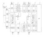
- FIG. 1shows a direct conversion based arrangement for realizing a dual frequency band transceiver, known from the Finnish Patent document FI 100286.
- a RF signal received by an antennais coupled by means of switch 104 either to a first receive branch (DCS) or second receive branch (GSM).
- DCSfirst receive branch
- GSMsecond receive branch
- the received signalis in the DCS frequency band, it is conducted to band-pass filter 106 , low-noise amplifier (LNA) 108 and bandpass filter 110 . After that the signal is brought to block 112 which produces signal components having a 90-degree phase difference.
- the in-phase component I and quadrature component Qare further conducted by means of switches 114 and 134 to mixers 116 and 136 .
- the mixersget their mixing signals from a DCS synthesizer 140 the frequency of which corresponds to the received carrier frequency so that the mixing produces the in-phase and quadrature components of the complex baseband signal.
- the baseband signalis further processed in the receive (RX) signal processing unit, block 139 .
- switch 104directs the received signal to the GSM branch which comprises, connected in series bandpass filter 126 , low-noise amplifier 128 , bandpass filter 130 and phase shifter 132 which generates two signals with a mutual phase difference of 90 degrees.
- the signalsare further conducted by means of switches 114 and 134 to mixers 116 and 136 where the mixing frequency is now determined by a signal coming from the GSM synthesizer 150 via switch 161 .
- the signals produced by the mixersare further conducted to the baseband RX signal processing unit 139 .
- the DCS synthesizercomprises in a known manner a phase-locked loop (PLL) which includes a voltage-controlled oscillator (VCO) 141 the output signal of which is amplified at amplifier 146 thus producing the synthesizer output signal.
- PLLphase-locked loop
- VCOvoltage-controlled oscillator
- the frequency of the signal from oscillator 141is divided by an integer Y in divider 142 and the resulting signal is conducted to phase comparator 143 .
- the frequency of the signal generated by reference oscillator 158is divided by an integer X in divider 144 and conducted to phase comparator 143 .
- the phase comparatorproduces a signal proportional to the phase difference of said two input signals, which signal is conducted to a low-pass filter (LPF) 145 producing a filtered signal that controls the voltage-controlled oscillator 141
- LPFlow-pass filter
- the phase-locked loop described aboveoperates in a known manner in which the output frequency of the synthesizer becomes locked to the frequency coming to the phase comparator from the reference frequency branch. The output frequency is controlled by varying the divisor Y.
- the GSM synthesizer 150comprises a voltage-controlled oscillator 150 , amplifier 156 , dividers 152 and 154 , phase comparator 153 and a low-pass filter 155 .
- the GSM synthesizeroperates like the DCS synthesizer described above, but the output frequency of the GSM synthesizer corresponds to GSM frequency bands.
- a baseband complex transmit (TX) signalis processed in a TX signal processing unit wherefrom the in-phase and quadrature components of the signal are conducted to mixers 162 and 182 that produce a carrier-frequency signal by multiplying the input signal by the mixing signal.
- switch 161selects the DCS synthesizer's output signal as the mixing signal.
- the carrier-frequency signalis conducted through switch 164 to the DCS branch where a 90-degree phase shift is first produced between the in-phase component and quadrature component, and the resulting signals are then summed, block 166 .
- the resulting DCS signalis conducted to bandpass filter 168 , amplifier 170 , and bandpass filter 172 .
- the RF signalthus produced is further conducted to the antenna 102 via switch 180 .
- the output signal of the GSM synthesizeris used as the mixing signal.
- the resulting carrier-frequency signalis conducted to the GSM branch in which it is processed in the same manner as in the DCS branch blocks 186 , 188 , 190 and 192 .
- the RF signal thus producedis conducted to the antenna 102 via switch 180 .
- One and the same antenna 102can be used in both transmission and reception if the TX and RX circuits are coupled to the antenna through a duplex filter, for example. If the apparatus is designed to operate in two or more frequency bands, it needs separate filters for each frequency band.
- circuit arrangement described abovehas, however, some disadvantages.
- An object of the inventionis to provide a simple solution for realizing a programmable transceiver operating in a plurality of systems in such a manner that the aforementioned disadvantages related to the prior art can be avoided.
- signal processingcan be performed using one and the same signal processing line regardless of the system. This is achieved using the signal processing steps set forth below.
- signal band limitingis advantageously performed at the baseband frequency so that there is no need for “steep” filters and, therefore, system-specific filter lines. Filtering can thus be performed as low-pass filtering using a filter with a controllable cut-off frequency. This way, it is possible to completely avoid separate system-specific channel filtering circuits.
- the synthesizer's operating frequencyis set higher than the frequencies used in the systems, it is possible to generate, in conjunction with the synthesizer frequency division, two mixing signals with a 90-degree phase difference, thus avoiding the need for phase shifters on the signal line and achieving a good phase accuracy.
- the circuit arrangement according to the inventionrequires only one TX signal branch and one RX signal branch. Moreover, one and the same synthesizer may be used to generate the mixing signals. Furthermore, there is no need for channel filters operating at the radio frequency. Therefore, the circuitry can be easily integrated. Since the invention involves only a few components, the advantages of the transceiver according to the invention include small size and low power consumption.
- FIG. 1shows a block diagram of a dual-band direct-conversion transceiver according to the prior art
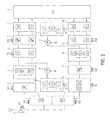
- FIG. 2shows in the form of block diagram a solution according to the invention for a direct-conversion transceiver operating in multiple systems.
- FIG. 1was already discussed in conjunction with the description of the prior art. Next, a transceiver according to the invention will be described, referring to FIG. 2 .
- FIG. 2shows in the form of block diagram a transceiver according to the invention.
- a RF signal received through an antennais conducted via matching circuits 1 to controllable bandpass filters 2 .
- the matching circuits 1may advantageously be controllable (AX) with respect to the operating frequency band.
- a controllable band-pass filter 2may be advantageously realized using a plurality of bandpass filters so that the RF signal is conducted via switch elements controlled by a control signal FX 1 from the matching circuit 1 to the bandpass filter that corresponds to the selected operating frequency band.
- the bandpass filtermay also be realized so as to be adjustable and tuneable by means of programming.
- the bandpass filtered carrier-frequency signalis further conducted to a low-noise amplifier 4 , the gain of which is advantageously controllable.
- the control signalis marked GX 1 in the drawing.
- amplifier 4it is also possible to have integrated amplifiers in connection with the bandpass filters.
- the signalis then conducted to a mixer 5 in which the carrier-frequency signal is mixed with an RX mixing signal at the receive frequency to produce a baseband quadrature signal.
- the RX mixing signalis advantageously generated by a synthesizer 10 the output signal frequency of which is divided by a divider 11 so as to correspond to the selected receive frequency.
- the synthesizer 10operates in a similar manner as the synthesizers depicted in FIG. 1 . Thus it comprises a voltage-controlled oscillator VCO which produces an output signal.
- the frequency of the VCO output signalis divided by S 1 in a divider in the phase-locked loop PLL.
- the resulting signalis conducted to a first input of a phase comparator in the phase-locked loop.
- the frequency of a signal generated by a reference oscillator in the phase-locked loop PLLis divided by an integer and conducted to a second input of the phase comparator.
- the phase comparatorproduces a signal which is proportional to the phase difference of the two input signals and conducted to a low-pass filter, and the filtered signal then controls the voltage-controlled oscillator VCO.
- the output frequencyis controlled by varying the divisor S 1 .
- the synthesizer output signalis divided in divider 11 by N 1 so that the RX mixing signal corresponds to the selected receive frequency band.
- the output frequency of the synthesizermay be e.g. in the 4-GHz band, so that with 2-GHz systems the synthesizer output frequency is divided by two, and with 1-GHz systems it is divided by four (N 1 ). This way, systems operating in the 1-GHz and 2-GHz bands can be covered with a synthesizer the operating frequency band of which is narrow with respect to the operating frequency.
- phase-shifted componentsmay be produced by a phase shifter in connection with the mixer or they may be produced as quotients generated already in the frequency divider 11 , thus achieving an accurate phase difference. Therefore, it is advantageous to use a synthesizer operating frequency which is a multiple of the highest system frequency.
- the in-phase component 1 and quadrature component Q from the mixer 5are further conducted to low-pass filters 6 .
- the higher cut-off frequency of the low-pass filtersis advantageously controllable with control signal FX 3 .
- the filteringcan be performed at a bandwidth corresponding to the selected radio interface, and since the filtering is performed at baseband, it is easy to get the filtering function steep. Also, no strict demands are set on the bandpass filtering ( 2 ) of the RF signal.
- the baseband signalis further conducted to a gain control block 7 which possibly includes an offset voltage correction block.
- a gain control block 7which possibly includes an offset voltage correction block.
- the amplifieradvantageously realizes automatic gain control (AGC).
- AGCautomatic gain control
- the signalis convened digital in an analog-to-digital converter 8 , and the digital baseband signal is further processed in a digital signal processor (DSP) 9 .
- DSPdigital signal processor
- Channel filteringmay also be performed digitally in the DSP, whereby the low-pass filtering of the baseband signal may be performed using a fixed cut-off frequency. Then, however, the dynamics of the analog-to-digital converter must be considerably better.
- a quadrature baseband signalis first digitally generated in block 9 on the basis of the information signal to be sent.
- the components of the digital signalare converted analog by digital-to-analog converters 14 , whereafter the analog signals are low-pass filtered by low-pass filters 15 .
- the cutoff frequency of the low-pass filterscan be controlled with control signal FX 4 so as to correspond to the specifications of the selected radio interface.
- a TX mixing signal at the carrier frequencyis generated by a synthesizer 13 and divider 12 .
- the synthesizer 13operates in a similar manner as the synthesizer 10 in the receiver pan. Moreover, the synthesizers may share a reference oscillator.
- the frequency of the synthesizer output signalis controlled with control signal 52 within the synthesizer's operating frequency range.
- the frequency of the output signal from synthesizer 13is divided in divider 12 so as to correspond to the selected transmission frequency band.
- Components phase-shifted by 90 degreesare generated from the TX mixing signal in order to perform complex mixing in mixer 16 .
- the phase-shifted componentsmay be generated in the same way as in the receiver part.
- the signal at the carrier frequencyis then amplified in an amplifier 17 , the gain of which is advantageously controllable in order to set the transmission power and realize automatic gain control (AGC).
- the control signalis marked GX 3 in FIG. 2 .
- the signalis then conducted to a power amplifier 18 .
- the operating frequency band of the power amplifieris advantageously selectable with control signal BX. This can be achieved e.g. such that the amplifier comprises partly separate signal lines for the different operating frequency bands.
- the RF signal generatedis filtered by a bandpass filter 3 .
- the pass band of the bandpass filteris advantageously controllable with control signal FX 2 . This can be realized in the same way as in the receiver part.
- the receiver and transmitter part filters 2 and 3are advantageously realized in duplex filter pairs for each transmit-receive frequency band associated with a given system.
- the filtersmay advantageously be surface acoustic wave (SAW) or bulk acoustic wave (BAW) filters so that several filters with their switches may be attached to one component.
- the control signals in the mobile station transceiver according to FIG. 2are preferably generated in a control block of the mobile station which advantageously comprises a processing unit such as a microprocessor.
- the control blockgenerates the signal on the basis of a system switch instruction input from the keypad of the mobile station, for example.
- System selectionmay be e.g. menu-based so that the desired system is selected by choosing it from a displayed menu by pressing a certain key on the keypad.
- the control blockthen generates the control signals that correspond to the selected system.
- the system switch instructionmay also come via the mobile communication system in such a manner that data received from the system may include a system switch instruction on the basis of which the control block performs the system switch.
- a control programis stored in a memory unit used by the control block, which control program monitors the received data and, as it detects a system switch instruction in the data, gives the central block an instruction to set the control signals into states according to the selection instruction.
- the solution according to the inventionmay be well applied to communication systems other than the mobile communication systems mentioned above.
- the solutionmay be used to realize e.g. a GPS receiver for the location of a mobile station or other apparatus.
- the operating frequencies mentionedare given by way of example only, and the implementation of the invention is in no way restricted to them.
- the solution according to the inventionmay be applied to all current coding techniques such as the narrow-band FDMA (Frequency Division Multiple Access) and TDMA (Time Division Multiple Access), as well as the broadband CDMA (Code Division Multiple Access) technique.
- the solution according to the inventionmay be used to realize an FM (Frequency Modulation) receiver.
Landscapes
- Engineering & Computer Science (AREA)
- Computer Networks & Wireless Communication (AREA)
- Signal Processing (AREA)
- Transceivers (AREA)
- Transmitters (AREA)
- Circuits Of Receivers In General (AREA)
- Mobile Radio Communication Systems (AREA)
Abstract
Description
- a carrier-frequency signal is received from a radio interface,
- the carrier-frequency signal is bandpass-filtered,
- the filtered carrier-frequency signal is amplified,
- an RX mixing signal at the receive frequency is generated,
- a complex baseband signal is generated from the received carrier-frequency signal by mixing it with the RX mixing signal,
- the baseband signal generated is low-pass-filtered,
- the baseband signal generated is amplified,
- the baseband signal is converted digital, and
- the baseband signal converted digital is processed to produce an information signal encoded and modulated into the received signal.
- a digital baseband quadrature signal is generated on the basis of the information signal to be transmitted,
- the digital baseband signal is converted analog,
- a TX mixing signal at the transmit frequency is generated,
- a carrier-frequency transmission signal is generated from the baseband signal by mixing it with the TX mixing signal,
- the carrier-frequency signal generated is amplified, and
- the transmission signal is sent to the radio interface.
- antenna means for receiving a radio-frequency signal,
- bandpass filter for filtering a carrier-frequency signal,
- first RX amplifier for amplifying the filtered carrier-frequency signal,
- means for generating an RX mixing signal at the receive frequency,
- mixing means for generating a complex baseband signal from the received signal using the RX mixing signal,
- low-pass filter for filtering the baseband signal,
- second amplifier for amplifying the baseband signal,
- analog-to-digital converter for converting the baseband signal digital, and
- means for processing the baseband signal converted digital to produce an information signal encoded and modulated into the received signal.
- means for generating a digital baseband quadrature signal on the basis of the information signal to be transmitted,
- digital-to-analog converter for converting the baseband transmission signal analog,
- synthesizer for generating a TX mixing signal at the transmit frequency, mixing means for producing a signal at the carrier frequency from the baseband transmission signal using the TX mixing signal,
- TX amplifier for amplifying the signal at the carrier frequency, and
- antenna means for transmitting the amplified transmission signal at the carrier frequency.
| DECT | PHS | |||||||
| GSM | Digital | Personal | ||||||
| Global System for | PDC | European | Handy | |||||
| IS-95 US | Mobile | Personal Digital | Cordless | Phone | ||||
| CELLULAR SYSTEM | AMPS | IS-54/-136 | CDMA | Communications | DCS 1800 | Cellular | Telephone | System |
| RX FREQ. | 869-894 | 869-894 | 869-894 | 935-960 | 1805-1880 | 810-826, | 1880-1900 | 1895-1918 |
| (MHz) | 1429-1453 | |||||||
| TX FREQ. | 824-849 | 824-849 | 824-849 | 890-915 | 1710-1785 | 940-956 | 1880-1900 | 1895-1918 |
| (MHz) | 1477-1501 | |||||||
| RF BANDWITH | 25 MHz | 25 MHz | 25 MHz | 25 MHz | 75 MHz | 16 MHz | 20 MHz | 23 MHz |
| 24 MHz | ||||||||
| MULTIPLE ACCESS | FDMA | TDMA/ | CDMA/FDMA | TDMA/FDMA | TDMA/ | TDMA/FDMA | TDMA/ | TDMA/ |
| METHOD | FDMA | FDMA | FDMA | FDMA | ||||
| DUPLEX METHOD | FDD | FDD | FDD | FDD | FDD | FDD | TDD | TDD |
| NUMBER OF | 832 | 832, | 20, | 124, | 374, | 1600, | 10, | 300, |
| CHANNELS | 3 users/ | 798 users/ | 8 users/channel | 8 users/ | 3 users/ | 12 users/ | 4 users/ | |
| channel | channel | channel | channel | channel | channel | |||
| CHANNEL SPACING | 30 kHz | 30 kHz | 1250 kHz | 200 kHz | 200 kHz | 25 kHz | 1.728 MHz | 300 kHz |
| MODULATION | FM | π/4DQPSK | QPSK/ | GMSK 0.3 | GMSK 0.3 | π/4 DQPSK | GFSK | π/4 DQPSK |
| OQPSK | Gaussian filter | Gaussian filter | 0.3 | |||||
| Gaussian | ||||||||
| filter | ||||||||
| CHANNEL BIT RATE | — | 48.6 kb/s | 1.2288 Mb/s | 270.833 kb/s | 270.833 kb/s | 42 kb/s | 1.152 MB/s | 384 kb/s |
| CELLULAR SYSTEM | WCDMA | |
| RX FREQ. (MHz) | 2110-2170 | 1900-1920 |
| TX FREQ. (MHz) | 1920-1980 | 1900-1920 |
| MULTIPLE ACCESS METHOD | CDMA | TDMA |
| DUPLEX METHOD | FDD | TDD |
| CHANNEL SPACING | 5 MHz | 5 MHz |
| MODULATION | QPSK |
| 144 kb/s in rural outdoor, | ||
| 500 kb/s in urban outdoor | ||
| and up to 2 Mb/s in indoor | ||
Claims (81)
Priority Applications (4)
| Application Number | Priority Date | Filing Date | Title |
|---|---|---|---|
| US13/614,272US8755834B2 (en) | 1998-11-26 | 2012-09-13 | Method and arrangement for transmitting and receiving RF signals through various radio interfaces of communication systems |
| US14/272,191US8838049B1 (en) | 1998-11-26 | 2014-05-07 | Method and arrangement for transmitting and receiving RF signals through various radio interfaces of communication systems |
| US14/272,820US9270301B2 (en) | 1998-11-26 | 2014-05-08 | Method and arrangement for transmitting and receiving RF signals through various radio interfaces of communication systems |
| US15/049,786US20170019129A1 (en) | 1998-11-26 | 2016-02-22 | Method and Arrangement for Transmitting and Receiving RF Signals Through Various Radio Interfaces of Communication Systems |
Applications Claiming Priority (6)
| Application Number | Priority Date | Filing Date | Title |
|---|---|---|---|
| FI982559 | 1998-11-26 | ||
| FI982559AFI112741B (en) | 1998-11-26 | 1998-11-26 | Method and apparatus for transmitting and receiving RF signals at various radio interfaces of data transmission systems |
| PCT/FI1999/000974WO2000031885A1 (en) | 1998-11-26 | 1999-11-25 | Method and arrangement for transmitting and receiving rf signals through various radio interfaces of communication systems |
| US85674601A | 2001-05-24 | 2001-05-24 | |
| US12/136,465US8768408B2 (en) | 1998-11-26 | 2008-06-10 | Method and arrangement for transmitting and receiving RF signals through various radio interfaces of communication systems |
| US13/614,272US8755834B2 (en) | 1998-11-26 | 2012-09-13 | Method and arrangement for transmitting and receiving RF signals through various radio interfaces of communication systems |
Related Parent Applications (1)
| Application Number | Title | Priority Date | Filing Date |
|---|---|---|---|
| US12/136,465ContinuationUS8768408B2 (en) | 1998-11-26 | 2008-06-10 | Method and arrangement for transmitting and receiving RF signals through various radio interfaces of communication systems |
Related Child Applications (1)
| Application Number | Title | Priority Date | Filing Date |
|---|---|---|---|
| US14/272,191ContinuationUS8838049B1 (en) | 1998-11-26 | 2014-05-07 | Method and arrangement for transmitting and receiving RF signals through various radio interfaces of communication systems |
Publications (2)
| Publication Number | Publication Date |
|---|---|
| US20130012142A1 US20130012142A1 (en) | 2013-01-10 |
| US8755834B2true US8755834B2 (en) | 2014-06-17 |
Family
ID=8552988
Family Applications (7)
| Application Number | Title | Priority Date | Filing Date |
|---|---|---|---|
| US09/856,746Expired - Fee RelatedUS7415247B1 (en) | 1998-11-26 | 1999-11-25 | Method and arrangement for transmitting and receiving RF signals through various radio interfaces of communication systems |
| US11/565,339AbandonedUS20070213025A1 (en) | 1998-11-26 | 2006-11-30 | Method and arrangement for transmitting and recieving rf signals through various radio interfaces of communication systems |
| US12/136,465Expired - Fee RelatedUS8768408B2 (en) | 1998-11-26 | 2008-06-10 | Method and arrangement for transmitting and receiving RF signals through various radio interfaces of communication systems |
| US13/614,272Expired - Fee RelatedUS8755834B2 (en) | 1998-11-26 | 2012-09-13 | Method and arrangement for transmitting and receiving RF signals through various radio interfaces of communication systems |
| US14/272,191Expired - Fee RelatedUS8838049B1 (en) | 1998-11-26 | 2014-05-07 | Method and arrangement for transmitting and receiving RF signals through various radio interfaces of communication systems |
| US14/272,820Expired - Fee RelatedUS9270301B2 (en) | 1998-11-26 | 2014-05-08 | Method and arrangement for transmitting and receiving RF signals through various radio interfaces of communication systems |
| US15/049,786AbandonedUS20170019129A1 (en) | 1998-11-26 | 2016-02-22 | Method and Arrangement for Transmitting and Receiving RF Signals Through Various Radio Interfaces of Communication Systems |
Family Applications Before (3)
| Application Number | Title | Priority Date | Filing Date |
|---|---|---|---|
| US09/856,746Expired - Fee RelatedUS7415247B1 (en) | 1998-11-26 | 1999-11-25 | Method and arrangement for transmitting and receiving RF signals through various radio interfaces of communication systems |
| US11/565,339AbandonedUS20070213025A1 (en) | 1998-11-26 | 2006-11-30 | Method and arrangement for transmitting and recieving rf signals through various radio interfaces of communication systems |
| US12/136,465Expired - Fee RelatedUS8768408B2 (en) | 1998-11-26 | 2008-06-10 | Method and arrangement for transmitting and receiving RF signals through various radio interfaces of communication systems |
Family Applications After (3)
| Application Number | Title | Priority Date | Filing Date |
|---|---|---|---|
| US14/272,191Expired - Fee RelatedUS8838049B1 (en) | 1998-11-26 | 2014-05-07 | Method and arrangement for transmitting and receiving RF signals through various radio interfaces of communication systems |
| US14/272,820Expired - Fee RelatedUS9270301B2 (en) | 1998-11-26 | 2014-05-08 | Method and arrangement for transmitting and receiving RF signals through various radio interfaces of communication systems |
| US15/049,786AbandonedUS20170019129A1 (en) | 1998-11-26 | 2016-02-22 | Method and Arrangement for Transmitting and Receiving RF Signals Through Various Radio Interfaces of Communication Systems |
Country Status (8)
| Country | Link |
|---|---|
| US (7) | US7415247B1 (en) |
| EP (1) | EP1133831B1 (en) |
| JP (1) | JP2002530995A (en) |
| CN (1) | CN1192499C (en) |
| AU (1) | AU1562800A (en) |
| DE (1) | DE69942878D1 (en) |
| FI (1) | FI112741B (en) |
| WO (1) | WO2000031885A1 (en) |
Cited By (6)
| Publication number | Priority date | Publication date | Assignee | Title |
|---|---|---|---|---|
| US20180241421A1 (en)* | 2015-08-21 | 2018-08-23 | Telefonaktiebolaget Lm Ericsson (Publ) | Signal Distribution Network |
| US10651957B2 (en) | 2018-03-28 | 2020-05-12 | Qualcomm Incorporated | Proximity detection using a hybrid transceiver |
| US10673479B2 (en)* | 2017-03-28 | 2020-06-02 | Qualcomm Incorporated | Range-based transmission parameter adjustment |
| US20230170973A1 (en)* | 2020-05-08 | 2023-06-01 | Telefonaktiebolaget Lm Ericsson (Publ) | Versatile aas receiver |
| US12028138B2 (en) | 2020-05-08 | 2024-07-02 | Telefonaktiebolaget Lm Ericsson (Publ) | Narrowband AAS receiver with data replay interfacing |
| US12362810B2 (en) | 2020-05-11 | 2025-07-15 | Telefonaktiebolaget Lm Ericsson (Publ) | Efficient PRACH scheduling |
Families Citing this family (66)
| Publication number | Priority date | Publication date | Assignee | Title |
|---|---|---|---|---|
| FI112741B (en)* | 1998-11-26 | 2003-12-31 | Nokia Corp | Method and apparatus for transmitting and receiving RF signals at various radio interfaces of data transmission systems |
| FI112561B (en) | 1999-06-10 | 2003-12-15 | Nokia Corp | Transmitter / receiver for transmitting and receiving an RF signal in at least two frequency ranges |
| DE10035116C2 (en)* | 2000-07-19 | 2002-12-19 | Infineon Technologies Ag | High-frequency interface for dual standard baseband chips |
| GB0028652D0 (en)* | 2000-11-24 | 2001-01-10 | Koninkl Philips Electronics Nv | Radio receiver |
| DE60224162T2 (en)* | 2001-01-12 | 2008-12-04 | Qualcomm, Inc., San Diego | REDUCTION OF THE LEAK SIGNAL OF A LOCALOSCILLATOR IN A DIRECT CONVERSION PROCESS |
| US6960962B2 (en)* | 2001-01-12 | 2005-11-01 | Qualcomm Inc. | Local oscillator leakage control in direct conversion processes |
| US6845126B2 (en)* | 2001-01-26 | 2005-01-18 | Telefonaktiebolaget L.M. Ericsson (Publ) | System and method for adaptive antenna impedance matching |
| US6961368B2 (en) | 2001-01-26 | 2005-11-01 | Ericsson Inc. | Adaptive antenna optimization network |
| DE10112575A1 (en)* | 2001-03-15 | 2002-10-02 | Siemens Ag | Method and device for generating mobile radio signals |
| EP1271792A1 (en)* | 2001-06-25 | 2003-01-02 | Motorola, Inc. | Low leakage local oscillator system |
| US7024169B2 (en)* | 2002-01-25 | 2006-04-04 | Qualcomm Incorporated | AMPS receiver using a zero-IF architecture |
| GB0204108D0 (en) | 2002-02-21 | 2002-04-10 | Analog Devices Inc | 3G radio |
| EP1476950B1 (en)* | 2002-02-21 | 2008-08-13 | MediaTek Inc. | Multimode Direct Conversion Receiver with Reconfigurable Baseband Combined Chebychev/inverse Chebychev Filter |
| JP4064764B2 (en)* | 2002-08-27 | 2008-03-19 | アルプス電気株式会社 | Mobile phone |
| AU2003301465A1 (en)* | 2002-10-16 | 2004-05-04 | Casio Computer Co., Ltd | Radio wave reception device, radio wave clock, and repeater |
| US7398068B2 (en) | 2003-05-05 | 2008-07-08 | Marvell International Ltd. | Dual antenna system having one phase lock loop |
| EP1627472B1 (en)* | 2003-05-23 | 2019-05-08 | Skyworks Solutions, Inc. | Shared functional block multi-mode multi-band communication transceivers |
| CN1625065A (en)* | 2003-12-05 | 2005-06-08 | 皇家飞利浦电子股份有限公司 | Receiver for radio communication system |
| US20060078068A1 (en)* | 2004-10-13 | 2006-04-13 | Aiguo Yan | Methods and apparatus for wireless communication |
| US7379752B2 (en)* | 2004-10-13 | 2008-05-27 | Mediatek Inc. | Methods and apparatus for communication in a wireless system |
| WO2006044607A1 (en) | 2004-10-13 | 2006-04-27 | Analog Devices, Inc. | Filters for communication systems |
| US7653168B2 (en) | 2005-01-12 | 2010-01-26 | Nokia Corporation | Digital clock dividing circuit |
| US7403750B2 (en)* | 2005-04-25 | 2008-07-22 | Nokia Corporation | Reuse of digital-to-analog converters in a multi-mode transmitter |
| US20060276149A1 (en)* | 2005-06-03 | 2006-12-07 | Microtune (Texas), L.P. | Multi-band broadcast tuner |
| US8180312B2 (en)* | 2005-08-04 | 2012-05-15 | Samsung Electronics Co., Ltd. | Receiver architecture for minimizing use of external bandpass filter between low-noise amplifier and first mixer |
| US7982533B2 (en) | 2005-08-22 | 2011-07-19 | Mediatek Usa Inc. | Transceiving system and compound filter |
| US20070064833A1 (en)* | 2005-09-12 | 2007-03-22 | Sahota Gurkanwal S | Multi-band radio frequency modulator |
| US7912428B2 (en)* | 2005-11-16 | 2011-03-22 | Broadcom Corporation | System and method providing variable-frequency IF conversion in a multimode communication device |
| JP2007295457A (en)* | 2006-04-27 | 2007-11-08 | Matsushita Electric Ind Co Ltd | Receiving device and electronic device using the same |
| TWI348269B (en)* | 2006-09-20 | 2011-09-01 | Mediatek Usa Inc | Transceiver and compound fileter |
| CN101155160B (en)* | 2006-09-29 | 2010-06-16 | 锐迪科科技有限公司 | Upconversion Mixer |
| CN100557990C (en)* | 2006-11-03 | 2009-11-04 | 华为技术有限公司 | Simplified method and device for a radio frequency front end |
| JP4289507B2 (en)* | 2006-11-08 | 2009-07-01 | 日本電波工業株式会社 | Synthesizer module |
| CA2639568C (en)* | 2007-09-14 | 2014-05-13 | Mohammad Reza Nezhad Ahmadi Mohabadi | Low-if transceiver architecture |
| US7724170B2 (en)* | 2007-12-02 | 2010-05-25 | The Chinese University Of Hong Kong | Sensor interface devices and amplifiers |
| EP2073394A1 (en)* | 2007-12-19 | 2009-06-24 | Alcatel-Lucent Deutschland AG | A method for transmission and reception in FDD mode or in TDD mode in an antenna network, an antenna network, a base station, a mobile station and a communication network therefor |
| JP5260131B2 (en)* | 2008-04-28 | 2013-08-14 | 株式会社エヌ・ティ・ティ・ドコモ | Base station, mobile station, and common information communication method |
| KR100999479B1 (en)* | 2008-08-07 | 2010-12-09 | 삼성전자주식회사 | Method and apparatus for improving broadcast reception performance of mobile terminal |
| US8064555B1 (en) | 2009-01-22 | 2011-11-22 | The United States Of America As Represented By The Secretary Of The Navy | Input/output multi-level channelizer amplifier |
| US8665995B2 (en) | 2009-06-23 | 2014-03-04 | Nokia Corporation | Dual channel transmission |
| EP2355362B1 (en)* | 2010-02-05 | 2015-01-14 | Intel Mobile Communications GmbH | Rf transceiver and modem comprising such a transceiver |
| US8977519B2 (en)* | 2010-02-12 | 2015-03-10 | Test Equipment Plus, Inc | Spectrum analyzer using multiple intermediate frequencies and multiple clock configurations for residual, spurious and image signal reduction |
| CN101888256B (en)* | 2010-04-01 | 2012-11-28 | 华东师范大学 | Multi-mode multi-frequency multi-application direct frequency conversion wireless transceiver |
| TWI495276B (en)* | 2010-05-04 | 2015-08-01 | Realtek Semiconductor Corp | Multi-mode wireless transceiver and multi-mode switching method thereof |
| CN102739278B (en)* | 2011-04-02 | 2015-01-07 | 苏州联科盛世科技有限公司 | 2.4G wireless transceiver chip with an intermediate frequency of 1MHz |
| WO2013007869A1 (en)* | 2011-07-13 | 2013-01-17 | Nokia Corporation | Dual or multiple sim standby and active using a single digital baseband |
| US8902796B2 (en)* | 2011-11-04 | 2014-12-02 | Broadcom Corporation | Power-efficient multi-mode transceiver synthesizer configurations |
| US20130156074A1 (en)* | 2011-12-14 | 2013-06-20 | Aviacomm Inc. | Wideband rf front-end |
| EP3108718A1 (en)* | 2014-02-17 | 2016-12-28 | Cortex Systems | Mobile interconnection device |
| DE102014108774A1 (en) | 2014-06-24 | 2016-01-07 | Intel IP Corporation | Apparatus and method for generating an oscillator signal |
| US9843342B2 (en) | 2014-08-12 | 2017-12-12 | Qorvo Us, Inc. | Tunable RF transmit/receive multiplexer |
| US9780866B2 (en) | 2014-08-12 | 2017-10-03 | Qorvo Us, Inc. | Configurable RF transmit/receive multiplexer |
| US10312960B2 (en)* | 2014-08-12 | 2019-06-04 | Qorvo Us, Inc. | Switchable RF transmit/receive multiplexer |
| TWI595705B (en)* | 2014-11-10 | 2017-08-11 | 萬達系統股份有限公司 | Mixed optimal frequency combiner (mfoc) and integrated antenna system with mfoc |
| EP3304798A4 (en)* | 2015-06-05 | 2019-01-16 | Wispry, Inc. | Adaptive multi-carrier filter response systems and methods |
| US9992722B2 (en) | 2015-12-14 | 2018-06-05 | Huawei Technologies Canada Co., Ltd. | Reconfigurable multi-mode and multi-bands radio architecture and transceiver |
| US10707947B2 (en)* | 2017-10-17 | 2020-07-07 | Carnegie Mellon University | Reconfigurable hybrid beamforming MIMO receiver with inter-band carrier aggregation and RF-domain LMS weight adaptation |
| US11569897B2 (en) | 2017-10-17 | 2023-01-31 | Carnegie Mellon University | Scalable, multi-layer MIMO transceiver |
| US10951295B2 (en) | 2018-10-17 | 2021-03-16 | Carnegie Mellon University | Reconfigurable fully-connected bidirectional hybrid beamforming transceiver |
| US10944541B2 (en)* | 2019-08-30 | 2021-03-09 | Intel Corporation | LO frequency generation using resonator |
| US11749896B1 (en)* | 2020-06-23 | 2023-09-05 | Massive Light, LLC | Omni-directional broadband low distortion coaxial horn antenna |
| US12237858B2 (en) | 2021-03-25 | 2025-02-25 | Skyworks Solutions, Inc. | Mobile devices with dual conversion of multiple frequency bands using a shared intermediate frequency |
| US12101108B2 (en)* | 2021-03-30 | 2024-09-24 | Skyworks Solutions, Inc. | Mobile devices with merged frequency range one and intermediate frequency signal path |
| US12395862B2 (en) | 2021-07-09 | 2025-08-19 | Mediatek Inc. | Apparatuses and methods for co-reception (Co-Rx) operation of multiple transceiver radios sharing the same antenna and low noise amplifier (LNA) |
| WO2023075129A1 (en)* | 2021-10-29 | 2023-05-04 | 삼성전자 주식회사 | Electronic device comprising duplexers comprising filters having properties which are adaptively changeable according to state |
| US20230299796A1 (en)* | 2022-03-16 | 2023-09-21 | Intel Corporation | Quadrature chirp generation |
Citations (105)
| Publication number | Priority date | Publication date | Assignee | Title |
|---|---|---|---|---|
| US4395776A (en) | 1979-09-27 | 1983-07-26 | Toyo Communication Equipment Co., Ltd. | Transmitter having a phase synchronizing system |
| US4731796A (en) | 1984-10-25 | 1988-03-15 | Stc, Plc | Multi-mode radio transceiver |
| US4736390A (en) | 1986-10-15 | 1988-04-05 | Itt Avionics, A Division Of Itt Corporation | Zero IF radio receiver apparatus |
| US4761798A (en) | 1987-04-02 | 1988-08-02 | Itt Aerospace Optical | Baseband phase modulator apparatus employing digital techniques |
| US4972455A (en) | 1989-06-23 | 1990-11-20 | Motorola, Inc. | Dual-bandwidth cellular telephone |
| US5187809A (en) | 1990-08-24 | 1993-02-16 | Motorola, Inc. | Dual mode automatic gain control |
| EP0581573A1 (en) | 1992-07-28 | 1994-02-02 | Nokia Mobile Phones Ltd. | Universal radio telephone |
| EP0581572A1 (en) | 1992-07-31 | 1994-02-02 | Nokia Mobile Phones Ltd. | Method and system for frequency converting |
| EP0633674A2 (en) | 1993-07-06 | 1995-01-11 | Mitsubishi Denki Kabushiki Kaisha | Radio-transceiver with means for reducing interference |
| US5438692A (en) | 1992-11-26 | 1995-08-01 | U.S. Philips Corporation | Direct conversion receiver |
| US5465409A (en) | 1994-03-07 | 1995-11-07 | Motorola, Inc. | Radio architecture with dual frequency source selection |
| US5483691A (en) | 1992-06-08 | 1996-01-09 | Motorola, Inc. | Zero intermediate frequency receiver having an automatic gain control circuit |
| US5511235A (en) | 1994-05-02 | 1996-04-23 | Motorola, Inc. | Apparatus for detecting a signaling channel during scanning including a controlled frequency converter circuit and a controlled filter bandwidth, and a method therefor |
| US5519885A (en) | 1991-11-05 | 1996-05-21 | Nokia Mobile Phones Ltd. | Method to generate different frequency signals in a digital radio telephone |
| US5557642A (en) | 1992-08-25 | 1996-09-17 | Wireless Access, Inc. | Direct conversion receiver for multiple protocols |
| US5564076A (en)* | 1993-06-25 | 1996-10-08 | Alcatel Mobile Communication France | Portable digital signal transceiver providing communication via a terrestrial network and via a satellite network |
| US5574985A (en) | 1992-02-14 | 1996-11-12 | Nokia Telecommunications Oy | Radio transmitter receiver for operation in plural radio systems having unequal bands of operating frequencies represented by channel numbers |
| US5584068A (en) | 1992-11-26 | 1996-12-10 | U.S. Philips Corporation | Direct conversion receiver |
| US5590412A (en) | 1993-11-19 | 1996-12-31 | Sanyo Electric Co., Ltd. | Communication apparatus using common amplifier for transmission and reception |
| CN1148444A (en) | 1994-09-14 | 1997-04-23 | 菲利浦电子有限公司 | Radio transmission system and a radio apparatus for use in such system |
| US5642378A (en) | 1994-11-17 | 1997-06-24 | Denheyer; Brian John | Dual mode analog and digital cellular phone |
| GB2312107A (en) | 1996-04-08 | 1997-10-15 | Matsushita Electric Industrial Co Ltd | Multiband receiver and quadrature demodulator with selectable local oscillator |
| US5694414A (en) | 1991-05-13 | 1997-12-02 | Omnipoint Corporation | Multi-band, multi-mode spread-spectrum communication system |
| US5710998A (en) | 1995-12-19 | 1998-01-20 | Motorola, Inc. | Method and apparatus for improved zero intermediate frequency receiver latency |
| US5722053A (en) | 1994-09-30 | 1998-02-24 | Qualcomm Incorporated | Multiple frequency communication device |
| GB2312108B (en) | 1996-04-08 | 1998-02-25 | Matsushita Electric Industrial Co Ltd | Multiband mobile unit communication apparatus |
| US5732330A (en) | 1996-07-02 | 1998-03-24 | Ericsson Inc. | Dual band transceiver |
| US5734970A (en) | 1995-02-08 | 1998-03-31 | Sony Corporation | Single oscillator transceiver with multiple frequency converters |
| US5752169A (en) | 1995-03-14 | 1998-05-12 | Sony Corporation | Integrated circuit and transmitter/receiver |
| US5757858A (en) | 1994-12-23 | 1998-05-26 | Qualcomm Incorporated | Dual-mode digital FM communication system |
| US5758271A (en) | 1995-06-02 | 1998-05-26 | Motorola, Inc. | Apparatus and method for optimizing the quality of a received signal in a radio receiver |
| CN1187270A (en) | 1995-06-07 | 1998-07-08 | 科姆萨特公司 | Digital downconverter/despreader for direct sequence spread spectrum CDMA communication system |
| US5786782A (en) | 1996-01-05 | 1998-07-28 | Nokia Mobile Phones Ltd. | Multiplexed signal conversion |
| US5794159A (en) | 1996-08-07 | 1998-08-11 | Nokia Mobile Phones Limited | Dual band mobile station employing cross-connected transmitter and receiver circuits |
| US5794119A (en) | 1995-11-21 | 1998-08-11 | Stanford Telecommunications, Inc. | Subscriber frequency control system and method in point-to-multipoint RF communication system |
| US5796772A (en) | 1991-05-13 | 1998-08-18 | Omnipoint Corporation | Multi-band, multi-mode spread-spectrum communication system |
| DE19712161A1 (en) | 1997-03-22 | 1998-09-24 | Lucent Tech Network Sys Gmbh | Device for pulse shaping high-frequency signals |
| US5822366A (en) | 1995-04-21 | 1998-10-13 | Nokia Mobile Phones Ltd. | Transceiver and method for generating and processing complex I/Q-signals |
| US5825809A (en) | 1996-01-20 | 1998-10-20 | Samsung Electronics Co., Ltd. | Digital filter having an energy level detector for selecting a coefficient |
| GB2287144B (en) | 1994-02-23 | 1998-11-18 | Motorola Israel Ltd | A radio device and a single-frequency radio transponder |
| EP0878974A1 (en) | 1997-05-16 | 1998-11-18 | Italtel s.p.a. | Communication method and a base transceiver station for a mobile radio communication system |
| EP0653851B1 (en) | 1993-11-12 | 1999-02-03 | Philips Patentverwaltung GmbH | Multiband radio transceiver |
| US5872810A (en) | 1996-01-26 | 1999-02-16 | Imec Co. | Programmable modem apparatus for transmitting and receiving digital data, design method and use method for said modem |
| US5894592A (en) | 1997-04-17 | 1999-04-13 | Motorala, Inc. | Wideband frequency synthesizer for direct conversion transceiver |
| US5896562A (en) | 1996-04-01 | 1999-04-20 | Nokia Mobile Phones, Ltd. | Transmitter/receiver for transmitting and receiving of an RF signal in two frequency bands |
| US5909643A (en) | 1995-11-24 | 1999-06-01 | Matsushita Electric Industrial Co., Ltd. | Transmitter power varying device having a bypass line for a power amplifier |
| US5926750A (en) | 1996-04-09 | 1999-07-20 | Nec Corporation | Receiver |
| US5926749A (en) | 1996-03-29 | 1999-07-20 | Alps Electric Co., Ltd. | Amplifier circuit having common AGC to IF and RF amplifiers for use in a transmitter |
| EP0782358A3 (en) | 1995-12-29 | 1999-07-21 | Lucent Technologies Inc. | Mobile communicator |
| US5953641A (en)* | 1995-12-22 | 1999-09-14 | Alcatel Mobile Phones | Multimode radio communication terminal |
| US5955992A (en) | 1998-02-12 | 1999-09-21 | Shattil; Steve J. | Frequency-shifted feedback cavity used as a phased array antenna controller and carrier interference multiple access spread-spectrum transmitter |
| US5963852A (en) | 1997-03-24 | 1999-10-05 | Ericsson Inc. | Dual band mobile station |
| US5983081A (en) | 1996-03-29 | 1999-11-09 | Nokia Mobile Phones, Ltd. | Method for generating frequencies in a direct conversion transceiver of a dual band radio communication system, a direct conversion transceiver of a dual band radio communication system and the use of this method and apparatus in a mobile station |
| US6006080A (en) | 1996-08-08 | 1999-12-21 | Matsushita Electric Industrial Co., Ltd. | Receiving mixer circuit for mobile radio transceiver designed to operate with multiple modulation modes and multiple frequency bands |
| US6009126A (en) | 1996-09-06 | 1999-12-28 | U.S. Philips Corporation | Zero-IF receiver |
| US6014571A (en) | 1996-06-10 | 2000-01-11 | Matsushita Electric Industrial Co., Ltd. | Multiband mobile unit communication apparatus |
| US6018553A (en) | 1996-09-18 | 2000-01-25 | Wireless Access | Multi-level mixer architecture for direct conversion of FSK signals |
| US6029052A (en) | 1997-07-01 | 2000-02-22 | Telefonaktiebolaget Lm Ericsson | Multiple-mode direct conversion receiver |
| US6029058A (en) | 1996-07-19 | 2000-02-22 | The Board Of Trustee Of The Leland Stanford Junior University | Spectrum control for direct conversion radio frequency reception |
| US6049722A (en) | 1994-09-13 | 2000-04-11 | Kabushiki Kaisha Toshiba | Radio communication apparatus for use in dual-mode radio communication system and having factor variable control means dependent on the set mode |
| US6054887A (en) | 1997-07-09 | 2000-04-25 | Denso Corporation | Offset voltage correction circuit |
| US6075996A (en) | 1996-11-28 | 2000-06-13 | Samsung Electronics Co., Ltd. | Intermediate frequency selecting device for use in dual band cellular telephone and method thereof |
| US6081697A (en) | 1997-03-21 | 2000-06-27 | Telefonaktiebolaget Lm Ericsson | Multi-carrier radio system and radio transceiver implementation |
| US6085075A (en) | 1997-12-05 | 2000-07-04 | U.S. Philips Corporation | Communication system, a communication device and a frequency synthesizer |
| US6125268A (en) | 1997-11-19 | 2000-09-26 | Ericsson Inc. | Tuning bandwidth minimization for low voltage dual band receiver |
| US6134452A (en) | 1998-11-23 | 2000-10-17 | Motorola, Inc. | Multiple band mixer with common local oscillator |
| US6151354A (en) | 1997-12-19 | 2000-11-21 | Rockwell Science Center | Multi-mode, multi-band, multi-user radio system architecture |
| US6163710A (en) | 1997-10-20 | 2000-12-19 | Ericsson, Inc. | Method and apparatus for compliance to multiple frequency plans |
| US6167245A (en) | 1998-05-29 | 2000-12-26 | Silicon Laboratories, Inc. | Method and apparatus for operating a PLL with a phase detector/sample hold circuit for synthesizing high-frequency signals for wireless communications |
| US6169733B1 (en)* | 1997-05-12 | 2001-01-02 | Northern Telecom Limited | Multiple mode capable radio receiver device |
| US6188877B1 (en) | 1997-07-03 | 2001-02-13 | Ericsson Inc. | Dual-band, dual-mode power amplifier with reduced power loss |
| US6194947B1 (en) | 1998-07-24 | 2001-02-27 | Global Communication Technology Inc. | VCO-mixer structure |
| US6208875B1 (en) | 1998-04-08 | 2001-03-27 | Conexant Systems, Inc. | RF architecture for cellular dual-band telephones |
| US6215988B1 (en) | 1997-05-15 | 2001-04-10 | Nokia Mobile Phones, Ltd. | Dual band architectures for mobile stations |
| US6243569B1 (en) | 1998-08-12 | 2001-06-05 | Analog Devices, Inc. | Direct conversion circuit for radio frequency signals |
| US6256511B1 (en) | 1996-02-16 | 2001-07-03 | Nortel Network Limited | Dual-mode radio architecture |
| US6269253B1 (en) | 1997-09-26 | 2001-07-31 | Matsushita Electric Industrial Co., Ltd. | Multi-mode wireless communication system |
| US6278864B1 (en) | 1995-04-20 | 2001-08-21 | Fujitsu Limited (Japan) | Radio tranceiver for data communications |
| US6282184B1 (en) | 1997-12-22 | 2001-08-28 | Nortel Networks Limited | Common digitizing rate for multiple air interfaces for generic cell sites in cellular radio |
| US6298226B1 (en) | 1998-11-30 | 2001-10-02 | Conexant Systems, Inc. | Receiver for RF signals |
| US6308050B1 (en) | 1998-03-23 | 2001-10-23 | Motorola, Inc. | Dual band mobile phone using the same intermediate frequency for both bands |
| US6337976B1 (en) | 1997-12-18 | 2002-01-08 | Nec Corporation | Selective-calling radio receiver using direct conversion method |
| US6356746B1 (en) | 1998-07-24 | 2002-03-12 | Matsushita Electric Industrial Co., Ltd. | Direct converting receiver |
| US6366765B1 (en) | 1998-03-30 | 2002-04-02 | Hitachi Kokusai Electric Inc. | Receiver |
| US6411646B1 (en) | 1998-06-30 | 2002-06-25 | Conexant Systems, Inc. | Direct conversion time division duplex radio, direct sequence spread spectrum cordless telephone |
| US6415001B1 (en) | 1998-12-01 | 2002-07-02 | Conexant Systems, Inc. | System and process for shared frequency source multi-band transmitters and receivers |
| US6434401B1 (en) | 1998-11-13 | 2002-08-13 | Sagem Sa | Method for the setting of a multiband mobile telephony transmitter-receiver and mobile telephone thus obtained |
| US6438462B1 (en) | 1996-03-26 | 2002-08-20 | Daimlerchrysler Ag | Semiconductor circuit for an electronic unit |
| US6449264B1 (en) | 1997-11-18 | 2002-09-10 | Nokia Mobile Phones Limited | Radio transceiver with two frequency bands |
| US6510310B1 (en) | 1998-01-26 | 2003-01-21 | Conexant Systems, Inc. | Dual mode phone architecture utilizing a single transmit-receive switch |
| US6516023B1 (en) | 1996-11-06 | 2003-02-04 | Nera Asa | System and method of downconversion where the received signal is downconverted |
| EP0797311A3 (en) | 1996-03-22 | 2003-02-05 | Matsushita Electric Industrial Co., Ltd. | Multiple-band mobile transceiver having a smaller number of local oscillators |
| EP0599409B1 (en) | 1992-11-26 | 2003-02-12 | Koninklijke Philips Electronics N.V. | A direct conversion receiver |
| US6535561B2 (en) | 1997-11-17 | 2003-03-18 | Ericsson Inc. | Dual-mode modulation systems and methods including oversampling of narrow bandwidth signals and DC offset compensation |
| US6535748B1 (en) | 1998-05-27 | 2003-03-18 | Nokia Mobile Phones Ltd. | Wireless communication transceiver having a dual mode of operation |
| US6535499B1 (en)* | 1998-02-27 | 2003-03-18 | Fujitsu Limited | Multi-mode communication device |
| US6584090B1 (en) | 1999-04-23 | 2003-06-24 | Skyworks Solutions, Inc. | System and process for shared functional block CDMA and GSM communication transceivers |
| US6584305B1 (en) | 1997-05-13 | 2003-06-24 | Matsushita Electric Industrial Co., Ltd. | Direct conversion radio receiving system using digital signal processing for channel filtering and down conversion to base band |
| US6600911B1 (en) | 1998-09-30 | 2003-07-29 | Mitsubishi Denki Kabushiki Kaisha | Even harmonic direct-conversion receiver, and a transmitting and receiving apparatus using the same |
| US6697606B1 (en) | 1997-11-06 | 2004-02-24 | Koninklijke Philips Electronics N.V. | Transceiver and a telecommunication system having a transceiver |
| US6813485B2 (en) | 1998-10-21 | 2004-11-02 | Parkervision, Inc. | Method and system for down-converting and up-converting an electromagnetic signal, and transforms for same |
| US6954624B2 (en) | 2000-09-12 | 2005-10-11 | Nokia Mobile Phones Ltd. | Transmitter and wireless communication device having a low power bypass branch |
| US7065327B1 (en) | 1998-09-10 | 2006-06-20 | Intel Corporation | Single-chip CMOS direct-conversion transceiver |
| EP0809366B1 (en) | 1996-05-24 | 2007-05-09 | VIA Telecom Co., Ltd. | A single chip solution for multimedia GSM mobile station systems |
| US7415247B1 (en) | 1998-11-26 | 2008-08-19 | Nokia Corporation | Method and arrangement for transmitting and receiving RF signals through various radio interfaces of communication systems |
Family Cites Families (40)
| Publication number | Priority date | Publication date | Assignee | Title |
|---|---|---|---|---|
| US4254504A (en) | 1978-08-08 | 1981-03-03 | International Telephone And Telegraph Corporation | Control apparatus for a transceiver employing a programmable memory |
| GB2177876A (en) | 1985-07-08 | 1987-01-28 | Philips Electronic Associated | Radio system and a transmitter and a receiver for use in the system |
| US4870699A (en) | 1986-03-26 | 1989-09-26 | General Electric Company | Method and apparatus for controlling the frequency of operation and at least one further variable operating parameter of a radio communications device |
| JPH0759162B2 (en) | 1986-04-26 | 1995-06-28 | 三菱化学ビーエーエスエフ株式会社 | Vegetation |
| US5311592A (en)* | 1986-06-11 | 1994-05-10 | Mcdonnell Douglas Corporation | Sagnac interferometer based secure communication system |
| GB2215945A (en) | 1988-03-26 | 1989-09-27 | Stc Plc | Digital direct conversion radio |
| JPH0357528A (en) | 1989-07-21 | 1991-03-12 | Sakamura Kikai Seisakusho:Kk | Manufacture of mouth piece for gas welding and its apparatus |
| DE69232943T2 (en) | 1991-05-13 | 2003-08-28 | Xircom Wireless, Inc. | TRANSMITTER / RECEIVER WITH TWO OPERATING MODES |
| JP3115050B2 (en) | 1991-09-11 | 2000-12-04 | 株式会社日立製作所 | Mobile communication equipment |
| JPH06188781A (en) | 1992-12-21 | 1994-07-08 | Toshiba Corp | Dual mode radio communication device |
| JPH06260961A (en) | 1993-03-04 | 1994-09-16 | Kyocera Corp | Digital mobile telephone set |
| IL114924A (en) | 1994-08-18 | 2000-02-17 | Omnipoint Corp | Multi-land multi-mode communication system |
| GB9418294D0 (en) | 1994-09-10 | 1994-10-26 | Philips Electronics Uk Ltd | Microwave transmitter and communications system |
| JPH08293815A (en) | 1994-11-01 | 1996-11-05 | Motorola Inc | Coprocessor performing plurality of communication task on integrated circuit |
| US5652903A (en) | 1994-11-01 | 1997-07-29 | Motorola, Inc. | DSP co-processor for use on an integrated circuit that performs multiple communication tasks |
| FI105865B (en) | 1994-11-14 | 2000-10-13 | Nokia Mobile Phones Ltd | Method and connection for power control and linearization of the transmission signal in a radio apparatus |
| EP0872021A1 (en) | 1995-08-04 | 1998-10-21 | Numa Technologies, Inc. | Universal rf receiver |
| US5867535A (en) | 1995-08-31 | 1999-02-02 | Northrop Grumman Corporation | Common transmit module for a programmable digital radio |
| JP3838447B2 (en) | 1995-08-31 | 2006-10-25 | ソニー株式会社 | Transmitting apparatus and receiving apparatus |
| JP3135832B2 (en) | 1995-12-04 | 2001-02-19 | 株式会社日立国際電気 | Composite terminal for mobile communication |
| JPH09261104A (en) | 1996-03-25 | 1997-10-03 | Matsushita Electric Ind Co Ltd | Multi-mode mobile radio |
| JP3813247B2 (en) | 1996-05-22 | 2006-08-23 | 松下電器産業株式会社 | Multiple mode shared transmission circuit |
| JP3080879B2 (en) | 1996-05-28 | 2000-08-28 | 埼玉日本電気株式会社 | Wireless telephone equipment |
| JPH1032519A (en) | 1996-07-16 | 1998-02-03 | Nec Corp | Radio communication equipment |
| US6035212A (en) | 1996-08-02 | 2000-03-07 | Lsi Logic Corporation | Multi-frequency wireless communication device |
| JPH1093475A (en) | 1996-09-17 | 1998-04-10 | Toshiba Corp | Complex system shared terminal |
| FI108486B (en) | 1997-01-31 | 2002-01-31 | Nokia Corp | Method and Circuit Arrangement for Processing Received Signals in a Communication System |
| US5926751A (en) | 1997-02-19 | 1999-07-20 | Motorola, Inc. | Method and apparatus for receiving communication signals |
| US6009119A (en) | 1997-03-25 | 1999-12-28 | Intermec Ip Corp. | Adaptive power leveling of an RF transceiver utilizing information stored in non-volatile memory |
| US6091966A (en) | 1997-09-29 | 2000-07-18 | Ericsson, Inc. | Dual-band, dual-mode power amplifier |
| US6028850A (en) | 1998-07-10 | 2000-02-22 | Hyundai Electronics America, Inc. | Wireless transceiver and frequency plan |
| FR2786342B1 (en) | 1998-08-28 | 2004-04-02 | Samsung Electronics Co Ltd | FREQUENCY SYNTHESIZER AND DOUBLE FREQUENCY HOPPING METHOD WITH FAST LOCKING TIME |
| GB9821088D0 (en) | 1998-09-30 | 1998-11-18 | Koninkl Philips Electronics Nv | Radio transmitter |
| US6366622B1 (en) | 1998-12-18 | 2002-04-02 | Silicon Wave, Inc. | Apparatus and method for wireless communications |
| US6484042B1 (en) | 1999-08-25 | 2002-11-19 | Skyworks Solutions, Inc. | Secondary automatic gain control loops for direct conversion CDMA receivers |
| US7082293B1 (en)* | 1999-10-21 | 2006-07-25 | Broadcom Corporation | Adaptive radio transceiver with CMOS offset PLL |
| US7463864B2 (en)* | 2004-04-09 | 2008-12-09 | Broadcom Corporation | Modified dual band direct conversion architecture that allows extensive digital calibration |
| US7672645B2 (en)* | 2006-06-15 | 2010-03-02 | Bitwave Semiconductor, Inc. | Programmable transmitter architecture for non-constant and constant envelope modulation |
| US8290447B2 (en)* | 2007-01-19 | 2012-10-16 | Wi-Lan Inc. | Wireless transceiver with reduced transmit emissions |
| US8102929B2 (en)* | 2009-02-12 | 2012-01-24 | Qualcomm Incorporated | Low power ultra wideband transceiver |
- 1998
- 1998-11-26FIFI982559Apatent/FI112741B/ennot_activeIP Right Cessation
- 1999
- 1999-11-25AUAU15628/00Apatent/AU1562800A/ennot_activeAbandoned
- 1999-11-25JPJP2000584607Apatent/JP2002530995A/enactivePending
- 1999-11-25CNCNB998138223Apatent/CN1192499C/ennot_activeExpired - Lifetime
- 1999-11-25USUS09/856,746patent/US7415247B1/ennot_activeExpired - Fee Related
- 1999-11-25DEDE69942878Tpatent/DE69942878D1/ennot_activeExpired - Lifetime
- 1999-11-25EPEP99958211Apatent/EP1133831B1/ennot_activeExpired - Lifetime
- 1999-11-25WOPCT/FI1999/000974patent/WO2000031885A1/enactiveApplication Filing
- 2006
- 2006-11-30USUS11/565,339patent/US20070213025A1/ennot_activeAbandoned
- 2008
- 2008-06-10USUS12/136,465patent/US8768408B2/ennot_activeExpired - Fee Related
- 2012
- 2012-09-13USUS13/614,272patent/US8755834B2/ennot_activeExpired - Fee Related
- 2014
- 2014-05-07USUS14/272,191patent/US8838049B1/ennot_activeExpired - Fee Related
- 2014-05-08USUS14/272,820patent/US9270301B2/ennot_activeExpired - Fee Related
- 2016
- 2016-02-22USUS15/049,786patent/US20170019129A1/ennot_activeAbandoned
Patent Citations (118)
| Publication number | Priority date | Publication date | Assignee | Title |
|---|---|---|---|---|
| US4395776A (en) | 1979-09-27 | 1983-07-26 | Toyo Communication Equipment Co., Ltd. | Transmitter having a phase synchronizing system |
| US4731796A (en) | 1984-10-25 | 1988-03-15 | Stc, Plc | Multi-mode radio transceiver |
| US4736390A (en) | 1986-10-15 | 1988-04-05 | Itt Avionics, A Division Of Itt Corporation | Zero IF radio receiver apparatus |
| US4761798A (en) | 1987-04-02 | 1988-08-02 | Itt Aerospace Optical | Baseband phase modulator apparatus employing digital techniques |
| US4972455A (en) | 1989-06-23 | 1990-11-20 | Motorola, Inc. | Dual-bandwidth cellular telephone |
| US5187809A (en) | 1990-08-24 | 1993-02-16 | Motorola, Inc. | Dual mode automatic gain control |
| US5796772A (en) | 1991-05-13 | 1998-08-18 | Omnipoint Corporation | Multi-band, multi-mode spread-spectrum communication system |
| US5694414A (en) | 1991-05-13 | 1997-12-02 | Omnipoint Corporation | Multi-band, multi-mode spread-spectrum communication system |
| US5519885A (en) | 1991-11-05 | 1996-05-21 | Nokia Mobile Phones Ltd. | Method to generate different frequency signals in a digital radio telephone |
| US5574985A (en) | 1992-02-14 | 1996-11-12 | Nokia Telecommunications Oy | Radio transmitter receiver for operation in plural radio systems having unequal bands of operating frequencies represented by channel numbers |
| US5483691A (en) | 1992-06-08 | 1996-01-09 | Motorola, Inc. | Zero intermediate frequency receiver having an automatic gain control circuit |
| EP0581573A1 (en) | 1992-07-28 | 1994-02-02 | Nokia Mobile Phones Ltd. | Universal radio telephone |
| EP0581572A1 (en) | 1992-07-31 | 1994-02-02 | Nokia Mobile Phones Ltd. | Method and system for frequency converting |
| US5557642A (en) | 1992-08-25 | 1996-09-17 | Wireless Access, Inc. | Direct conversion receiver for multiple protocols |
| US5438692A (en) | 1992-11-26 | 1995-08-01 | U.S. Philips Corporation | Direct conversion receiver |
| US5584068A (en) | 1992-11-26 | 1996-12-10 | U.S. Philips Corporation | Direct conversion receiver |
| EP0599409B1 (en) | 1992-11-26 | 2003-02-12 | Koninklijke Philips Electronics N.V. | A direct conversion receiver |
| US5564076A (en)* | 1993-06-25 | 1996-10-08 | Alcatel Mobile Communication France | Portable digital signal transceiver providing communication via a terrestrial network and via a satellite network |
| EP0631400B1 (en) | 1993-06-25 | 1999-09-15 | Alcatel | Portable transmitting and receiving device for two-mode digital signals |
| US5548825A (en) | 1993-07-06 | 1996-08-20 | Mitsubishi Denki Kabushiki Kaisha | Radio transmitter with active band-pass filtering |
| EP0633674A2 (en) | 1993-07-06 | 1995-01-11 | Mitsubishi Denki Kabushiki Kaisha | Radio-transceiver with means for reducing interference |
| EP0653851B1 (en) | 1993-11-12 | 1999-02-03 | Philips Patentverwaltung GmbH | Multiband radio transceiver |
| US5590412A (en) | 1993-11-19 | 1996-12-31 | Sanyo Electric Co., Ltd. | Communication apparatus using common amplifier for transmission and reception |
| GB2287144B (en) | 1994-02-23 | 1998-11-18 | Motorola Israel Ltd | A radio device and a single-frequency radio transponder |
| US5465409A (en) | 1994-03-07 | 1995-11-07 | Motorola, Inc. | Radio architecture with dual frequency source selection |
| US5511235A (en) | 1994-05-02 | 1996-04-23 | Motorola, Inc. | Apparatus for detecting a signaling channel during scanning including a controlled frequency converter circuit and a controlled filter bandwidth, and a method therefor |
| US6049722A (en) | 1994-09-13 | 2000-04-11 | Kabushiki Kaisha Toshiba | Radio communication apparatus for use in dual-mode radio communication system and having factor variable control means dependent on the set mode |
| US5751249A (en) | 1994-09-14 | 1998-05-12 | U.S. Philips Corporation | Radio transmission system and a radio apparatus for use in such a system |
| CN1148444A (en) | 1994-09-14 | 1997-04-23 | 菲利浦电子有限公司 | Radio transmission system and a radio apparatus for use in such system |
| US5722053A (en) | 1994-09-30 | 1998-02-24 | Qualcomm Incorporated | Multiple frequency communication device |
| US5758266A (en) | 1994-09-30 | 1998-05-26 | Qualcomm Incorporated | Multiple frequency communication device |
| US5642378A (en) | 1994-11-17 | 1997-06-24 | Denheyer; Brian John | Dual mode analog and digital cellular phone |
| US5757858A (en) | 1994-12-23 | 1998-05-26 | Qualcomm Incorporated | Dual-mode digital FM communication system |
| US5734970A (en) | 1995-02-08 | 1998-03-31 | Sony Corporation | Single oscillator transceiver with multiple frequency converters |
| US5752169A (en) | 1995-03-14 | 1998-05-12 | Sony Corporation | Integrated circuit and transmitter/receiver |
| US6278864B1 (en) | 1995-04-20 | 2001-08-21 | Fujitsu Limited (Japan) | Radio tranceiver for data communications |
| US5822366A (en) | 1995-04-21 | 1998-10-13 | Nokia Mobile Phones Ltd. | Transceiver and method for generating and processing complex I/Q-signals |
| US5758271A (en) | 1995-06-02 | 1998-05-26 | Motorola, Inc. | Apparatus and method for optimizing the quality of a received signal in a radio receiver |
| CN1187270A (en) | 1995-06-07 | 1998-07-08 | 科姆萨特公司 | Digital downconverter/despreader for direct sequence spread spectrum CDMA communication system |
| US5794119A (en) | 1995-11-21 | 1998-08-11 | Stanford Telecommunications, Inc. | Subscriber frequency control system and method in point-to-multipoint RF communication system |
| US5909643A (en) | 1995-11-24 | 1999-06-01 | Matsushita Electric Industrial Co., Ltd. | Transmitter power varying device having a bypass line for a power amplifier |
| US5710998A (en) | 1995-12-19 | 1998-01-20 | Motorola, Inc. | Method and apparatus for improved zero intermediate frequency receiver latency |
| US5953641A (en)* | 1995-12-22 | 1999-09-14 | Alcatel Mobile Phones | Multimode radio communication terminal |
| EP0782358A3 (en) | 1995-12-29 | 1999-07-21 | Lucent Technologies Inc. | Mobile communicator |
| US5786782A (en) | 1996-01-05 | 1998-07-28 | Nokia Mobile Phones Ltd. | Multiplexed signal conversion |
| US5825809A (en) | 1996-01-20 | 1998-10-20 | Samsung Electronics Co., Ltd. | Digital filter having an energy level detector for selecting a coefficient |
| US5872810A (en) | 1996-01-26 | 1999-02-16 | Imec Co. | Programmable modem apparatus for transmitting and receiving digital data, design method and use method for said modem |
| US6256511B1 (en) | 1996-02-16 | 2001-07-03 | Nortel Network Limited | Dual-mode radio architecture |
| EP0797311A3 (en) | 1996-03-22 | 2003-02-05 | Matsushita Electric Industrial Co., Ltd. | Multiple-band mobile transceiver having a smaller number of local oscillators |
| US6438462B1 (en) | 1996-03-26 | 2002-08-20 | Daimlerchrysler Ag | Semiconductor circuit for an electronic unit |
| US5926749A (en) | 1996-03-29 | 1999-07-20 | Alps Electric Co., Ltd. | Amplifier circuit having common AGC to IF and RF amplifiers for use in a transmitter |
| DE69736793T2 (en) | 1996-03-29 | 2007-02-01 | Nokia Corp. | A method of generating frequencies in a direct conversion transceiver of a dual band radio communication system, a direct conversion transceiver of a dual band radio communication system, and the use of this method and apparatus in a mobile station |
| EP0798880B1 (en) | 1996-03-29 | 2006-10-11 | Nokia Corporation | Method for generating frequencies in a direct conversion transceiver of a dual band radio communication system, a direct conversion transceiver of a dual band radio communication system and the use of this method and apparatus in a mobile station |
| US5983081A (en) | 1996-03-29 | 1999-11-09 | Nokia Mobile Phones, Ltd. | Method for generating frequencies in a direct conversion transceiver of a dual band radio communication system, a direct conversion transceiver of a dual band radio communication system and the use of this method and apparatus in a mobile station |
| US5896562A (en) | 1996-04-01 | 1999-04-20 | Nokia Mobile Phones, Ltd. | Transmitter/receiver for transmitting and receiving of an RF signal in two frequency bands |
| DE69737000T2 (en) | 1996-04-01 | 2007-07-05 | Nokia Corp. | Radio transmitter Receiver for sending and receiving MF signals in two bands |
| EP0800283B1 (en) | 1996-04-01 | 2006-11-29 | Nokia Corporation | Transmitter/receiver for transmitting and receiving of an RF signal in two frequency bands |
| US6175746B1 (en) | 1996-04-08 | 2001-01-16 | Matsushita Electric Industrial Co., Ltd. | Multiband mobile unit communication apparatus |
| GB2312108B (en) | 1996-04-08 | 1998-02-25 | Matsushita Electric Industrial Co Ltd | Multiband mobile unit communication apparatus |
| GB2312107A (en) | 1996-04-08 | 1997-10-15 | Matsushita Electric Industrial Co Ltd | Multiband receiver and quadrature demodulator with selectable local oscillator |
| US5926750A (en) | 1996-04-09 | 1999-07-20 | Nec Corporation | Receiver |
| EP0809366B1 (en) | 1996-05-24 | 2007-05-09 | VIA Telecom Co., Ltd. | A single chip solution for multimedia GSM mobile station systems |
| DE69735156T2 (en) | 1996-06-10 | 2006-08-10 | Matsushita Electric Industrial Co., Ltd., Kadoma | Multi-band communication device |
| US6014571A (en) | 1996-06-10 | 2000-01-11 | Matsushita Electric Industrial Co., Ltd. | Multiband mobile unit communication apparatus |
| EP0813312B1 (en) | 1996-06-10 | 2006-01-25 | Matsushita Electric Industrial Co., Ltd. | Multiband mobile unit communication apparatus |
| US5732330A (en) | 1996-07-02 | 1998-03-24 | Ericsson Inc. | Dual band transceiver |
| US6029058A (en) | 1996-07-19 | 2000-02-22 | The Board Of Trustee Of The Leland Stanford Junior University | Spectrum control for direct conversion radio frequency reception |
| US5794159A (en) | 1996-08-07 | 1998-08-11 | Nokia Mobile Phones Limited | Dual band mobile station employing cross-connected transmitter and receiver circuits |
| US6006080A (en) | 1996-08-08 | 1999-12-21 | Matsushita Electric Industrial Co., Ltd. | Receiving mixer circuit for mobile radio transceiver designed to operate with multiple modulation modes and multiple frequency bands |
| EP0823788A3 (en) | 1996-08-08 | 2002-10-30 | Matsushita Electric Industrial Co., Ltd. | Receiving mixer circuit for mobile radio transceiver designed to operate with multiple modulation modes and multiple frequency bands |
| US6009126A (en) | 1996-09-06 | 1999-12-28 | U.S. Philips Corporation | Zero-IF receiver |
| US6018553A (en) | 1996-09-18 | 2000-01-25 | Wireless Access | Multi-level mixer architecture for direct conversion of FSK signals |
| US6516023B1 (en) | 1996-11-06 | 2003-02-04 | Nera Asa | System and method of downconversion where the received signal is downconverted |
| US6075996A (en) | 1996-11-28 | 2000-06-13 | Samsung Electronics Co., Ltd. | Intermediate frequency selecting device for use in dual band cellular telephone and method thereof |
| US6081697A (en) | 1997-03-21 | 2000-06-27 | Telefonaktiebolaget Lm Ericsson | Multi-carrier radio system and radio transceiver implementation |
| DE19712161A1 (en) | 1997-03-22 | 1998-09-24 | Lucent Tech Network Sys Gmbh | Device for pulse shaping high-frequency signals |
| US5963852A (en) | 1997-03-24 | 1999-10-05 | Ericsson Inc. | Dual band mobile station |
| US5894592A (en) | 1997-04-17 | 1999-04-13 | Motorala, Inc. | Wideband frequency synthesizer for direct conversion transceiver |
| US6169733B1 (en)* | 1997-05-12 | 2001-01-02 | Northern Telecom Limited | Multiple mode capable radio receiver device |
| US6584305B1 (en) | 1997-05-13 | 2003-06-24 | Matsushita Electric Industrial Co., Ltd. | Direct conversion radio receiving system using digital signal processing for channel filtering and down conversion to base band |
| US6215988B1 (en) | 1997-05-15 | 2001-04-10 | Nokia Mobile Phones, Ltd. | Dual band architectures for mobile stations |
| EP0878974A1 (en) | 1997-05-16 | 1998-11-18 | Italtel s.p.a. | Communication method and a base transceiver station for a mobile radio communication system |
| US6029052A (en) | 1997-07-01 | 2000-02-22 | Telefonaktiebolaget Lm Ericsson | Multiple-mode direct conversion receiver |
| US6188877B1 (en) | 1997-07-03 | 2001-02-13 | Ericsson Inc. | Dual-band, dual-mode power amplifier with reduced power loss |
| US6054887A (en) | 1997-07-09 | 2000-04-25 | Denso Corporation | Offset voltage correction circuit |
| US6269253B1 (en) | 1997-09-26 | 2001-07-31 | Matsushita Electric Industrial Co., Ltd. | Multi-mode wireless communication system |
| US6163710A (en) | 1997-10-20 | 2000-12-19 | Ericsson, Inc. | Method and apparatus for compliance to multiple frequency plans |
| US6697606B1 (en) | 1997-11-06 | 2004-02-24 | Koninklijke Philips Electronics N.V. | Transceiver and a telecommunication system having a transceiver |
| US6535561B2 (en) | 1997-11-17 | 2003-03-18 | Ericsson Inc. | Dual-mode modulation systems and methods including oversampling of narrow bandwidth signals and DC offset compensation |
| US6449264B1 (en) | 1997-11-18 | 2002-09-10 | Nokia Mobile Phones Limited | Radio transceiver with two frequency bands |
| US6125268A (en) | 1997-11-19 | 2000-09-26 | Ericsson Inc. | Tuning bandwidth minimization for low voltage dual band receiver |
| US6484038B1 (en) | 1997-11-19 | 2002-11-19 | Ericsson Inc. | Method and apparatus for generating a plurality of reference frequencies in a mobile phone using a common crystal reference oscillator |
| US6085075A (en) | 1997-12-05 | 2000-07-04 | U.S. Philips Corporation | Communication system, a communication device and a frequency synthesizer |
| US6337976B1 (en) | 1997-12-18 | 2002-01-08 | Nec Corporation | Selective-calling radio receiver using direct conversion method |
| US6151354A (en) | 1997-12-19 | 2000-11-21 | Rockwell Science Center | Multi-mode, multi-band, multi-user radio system architecture |
| US6282184B1 (en) | 1997-12-22 | 2001-08-28 | Nortel Networks Limited | Common digitizing rate for multiple air interfaces for generic cell sites in cellular radio |
| US6510310B1 (en) | 1998-01-26 | 2003-01-21 | Conexant Systems, Inc. | Dual mode phone architecture utilizing a single transmit-receive switch |
| US5955992A (en) | 1998-02-12 | 1999-09-21 | Shattil; Steve J. | Frequency-shifted feedback cavity used as a phased array antenna controller and carrier interference multiple access spread-spectrum transmitter |
| US6535499B1 (en)* | 1998-02-27 | 2003-03-18 | Fujitsu Limited | Multi-mode communication device |
| US6308050B1 (en) | 1998-03-23 | 2001-10-23 | Motorola, Inc. | Dual band mobile phone using the same intermediate frequency for both bands |
| US6366765B1 (en) | 1998-03-30 | 2002-04-02 | Hitachi Kokusai Electric Inc. | Receiver |
| US6208875B1 (en) | 1998-04-08 | 2001-03-27 | Conexant Systems, Inc. | RF architecture for cellular dual-band telephones |
| US6535748B1 (en) | 1998-05-27 | 2003-03-18 | Nokia Mobile Phones Ltd. | Wireless communication transceiver having a dual mode of operation |
| US6167245A (en) | 1998-05-29 | 2000-12-26 | Silicon Laboratories, Inc. | Method and apparatus for operating a PLL with a phase detector/sample hold circuit for synthesizing high-frequency signals for wireless communications |
| US6411646B1 (en) | 1998-06-30 | 2002-06-25 | Conexant Systems, Inc. | Direct conversion time division duplex radio, direct sequence spread spectrum cordless telephone |
| US6356746B1 (en) | 1998-07-24 | 2002-03-12 | Matsushita Electric Industrial Co., Ltd. | Direct converting receiver |
| US6194947B1 (en) | 1998-07-24 | 2001-02-27 | Global Communication Technology Inc. | VCO-mixer structure |
| US6243569B1 (en) | 1998-08-12 | 2001-06-05 | Analog Devices, Inc. | Direct conversion circuit for radio frequency signals |
| US7065327B1 (en) | 1998-09-10 | 2006-06-20 | Intel Corporation | Single-chip CMOS direct-conversion transceiver |
| US6600911B1 (en) | 1998-09-30 | 2003-07-29 | Mitsubishi Denki Kabushiki Kaisha | Even harmonic direct-conversion receiver, and a transmitting and receiving apparatus using the same |
| US6813485B2 (en) | 1998-10-21 | 2004-11-02 | Parkervision, Inc. | Method and system for down-converting and up-converting an electromagnetic signal, and transforms for same |
| US6434401B1 (en) | 1998-11-13 | 2002-08-13 | Sagem Sa | Method for the setting of a multiband mobile telephony transmitter-receiver and mobile telephone thus obtained |
| US6134452A (en) | 1998-11-23 | 2000-10-17 | Motorola, Inc. | Multiple band mixer with common local oscillator |
| US7415247B1 (en) | 1998-11-26 | 2008-08-19 | Nokia Corporation | Method and arrangement for transmitting and receiving RF signals through various radio interfaces of communication systems |
| US6298226B1 (en) | 1998-11-30 | 2001-10-02 | Conexant Systems, Inc. | Receiver for RF signals |
| US6415001B1 (en) | 1998-12-01 | 2002-07-02 | Conexant Systems, Inc. | System and process for shared frequency source multi-band transmitters and receivers |
| US6584090B1 (en) | 1999-04-23 | 2003-06-24 | Skyworks Solutions, Inc. | System and process for shared functional block CDMA and GSM communication transceivers |
| US6954624B2 (en) | 2000-09-12 | 2005-10-11 | Nokia Mobile Phones Ltd. | Transmitter and wireless communication device having a low power bypass branch |
Non-Patent Citations (47)
| Title |
|---|
| Abidi, "Direct Conversion Radio Transceivers for Digital Communications", Dept. of Electr. Eng., California Univer., Los Angeles, CA, Journal, publication date Dec. 1995, vol. 30, No. 12. |
| B. Gilbert, "A Precise Four-Quadrant Multiplier with Subnanosecond Response," IEEE Journal Solid-State Circuits, Dec. 1968. |
| Beckwith, B., "Dual Band Integrated Power Amplifier with Switchable Interstage Match", Motorola, Jun. 1997, pp. 84-85. |
| Behzad Razavi, RF Microelectronics, 1998, Prentice Halls, Inc., 10th Edition, pp. 150-153. |
| Complainant's Nokia Corporation, Nokia Inc., and Intellisync Corporation Opening Claim Construction Brief, Investigation No. 337-TA-847, executed Dec. 20, 2012, 106 pages. |
| Complainants' Nokia Corporation, Nokia Inc., and Intellisync Corporation Post-Markman-Hearing Brief, Investigation No. 337-TA-847, executed Feb. 13, 2013, 49 pages. |
| Complainants' Nokia Corporation, Nokia Inc., and Intellisync Corporation Responsive Claim Construction Brief, Investigation No. 337-TA-847, executed Jan. 8, 2013, 48 pages. |
| Complaint, HTC with English translation, dated May 2, 2012, 92 pages. |
| DE Response to Nullity Action as filed, dated Oct. 7, 2013, with English translation, 91 pages. |
| Defendant/Counteraction Claimant's Response to Claimant/Counteraction Defendant's Notice to Admit Facts dated Mar. 27, 2013, HTC Corporation and Nokia Corporation, 9 pages. |
| Document HTC115, HTC Europe Co. Ltd./Nokia Corporation, dated Jan. 17, 2013, 30 pages (HL4). |
| Document HTC115, HTC Europe Co. Ltd./Nokia Corporation, dated Nov. 15, 2013, 36 pages (HL24). |
| Document, Samson & Partner, HTC Europe Co. Ltd. and Nokia Corporation, dated Oct. 7, 2013, 47 pages, German language (K94). |
| Expert Report of James Arthur Crawford, HTC Corporation and Nokia Corporation, executed Jul. 24, 2013, 86 pages. |
| Fernandez-Duran, A., et al., "Zero-IF Receiver Architecture for Multistandard Compatible Radio Systems. GIRAFE Project", IEEE 1996, pp. 1052-1056. |
| Final Expert Report of Professor Bram Nauta (Patents and Prior Art), HTC Corporation and Nokia Corporation, executed Jul. 5, 2013, 106 pages. |
| Final Reply Report of Professor Bram Nauta (Patents and Prior Art), HTC Corporation and Nokia Corporation, executed Jul. 25, 2013, 18 pages. |
| Gray, et al., "Future Directions in Silicon ICS for RF Personal Communications", Dept. of Electr. Eng. & Comput. Sci., California University, Berkely, CA, publication date May 14, 1995, pp. 83-90. |
| Grounds of Invalidity, HTC Corporation and Nokia Corporation, executed May 17, 2012, 2 pages. |
| Hanusch, T., et al., "Analog Baseband-IC for Dual Mode Direct Conversion receiver", Proc. ESSCIRC., Sep. 1996, pp. 244-249. |
| HTC Corporation and Nokia Corporation, Grounds of Invalidity, Claim No. HC12 F02047, executed May 17, 2012, 2 pages. |
| HTC Reply with English Translation dated Nov. 15, 2013, 71 pages. |
| International Organisation for Standardisation Organisation Interntionale de Normalisation, ISO/IEC JTC/SC29/WG11, Coding of Moving Pictures and Associated Audio, N0801, Information Technology-Generic Coding of Moving Pictures and Associated Audio: Systems, Recommendation H.222.0, ISO/IEC 13818-1, draft of 1540 Sun Nov. 13, 1994, 161 pages. |
| Kuo, C., "Multi-Standard DSP Based Wireless System", ICSP'98 Conference, vol. II of II, Oct. 12-16, 1998, pp. 1712-1728. |
| MC 1496 Datasheet, Motorola, Balanced Modulators/Demodulators, 1996, 12 pages. |
| Nguyen, C.T.-C., "Communications Applications of Microelectromechanical Systems", Proceedings, 1998 Sensors Expo, May 19-21, 1998, pp. 447-455. |
| Nullity Complaint HTC Europe Co. Ltd. v. Nokia Corporation Re: EP1133831 (DE69942878.5), dated Jan. 17, 2013, with English translation, 59 pages. |
| Order No. 8: Construing Terms of the Asserted Patents, In the Matter of Certain Electronic Devices, Including Mobile Phones and Tablet Computers, and Components Thereof, Investigation No. 337-TA-847, dated Mar. 21, 2013, 84 pages. |
| Order No. 9: Errata, In the Matter of Certain Electronic Devices, Including Mobile Phones and Tablet Computers, and Components Thereof, Investigation No. 337-TA-847, dated Mar. 25, 2013, 3 pages. |
| Proof of Publication date (Nov. 6, 1997) of book Razavi, Behzad, RF Microelectronics, Prentice Hall, 1st Edition by amazon.com under product detail section, and paper of when it was received by USPTO (Nov. 23, 1998). |
| Public Version of Initial Determination on Violation of Section 337 and Recommended Determination on Remedy and Bond, In the Matter of Certain Electronic Devices, Including Mobile Phones and Tablet Computers, and Components, Thereof, Investion No. 337-TA-847, dated Sep. 23, 2013, 239 pages. |
| Rejoinder EP1133831 B1, Bird & Bird LLP v. Hogan Lovells International LLP, document dated Nov. 15, 2013, 87 pages. |
| Replik LG Dusseldorf, dated Jun. 7, 2013, with English translation, 71 pages. |
| Respondents HTC Corp. and HTC America, Inc.'s Responsive Claim Construction Brief, Investigation No. 337-TA-847, executed Jan. 8, 2013, 42 pages. |
| Respondents HTC Corp. and HTC America, Inc's Opening Claim Construction Brief, Investigation No. 337-TA-847, executed Dec. 20, 2012, 63 pages. |
| Respondents HTC Corp. and HTC America, Inc's Supplemental Claim Construction Brief, Investigation No. 337-TA-847, executed Feb. 13, 2013, 43 pages. |
| RF Case/Case 1, HTC's Statements of Case on Validity on EP(UK) 0 998 024 and EP(UK) 1 133 831, HTC Corporation and Nokia Corporation, 6 pages, executed Jan. 14, 2013. |
| Sergio Graffi, et al., "New Macromodels and Measurements for the Analysis of EMI Effects in 741 Op-Amp Circuits," IEEE Trans. on Electromagnetic Compatiblity, Feb. 1991. |
| Summons to Appear Before the Tribunal De Grande Instance de Paris, Sep. 2013, with English translation, 134 pages. |
| Tham, J.L., e t al., "A 2.7V 900MHz/1.96GHz Dual-Band Transceiver IC for Digital Wireless Communication", IEEE CICC 1998 Conference, pp. 559-569. |
| Tham, J.L., et al., "A Direct-Conversion Transceiver Chip Set for 900 MHz (ISM Band) Spread-Spectrum Digital Cordless Telephone", ISCAS 1996 Conference, May 12-15, vol. 4, 1996, pp. 85-88. |
| Translation Statement of Defence Regional Court Dusseldorf, Hogan Lovells, dated Jan. 18, 2013, 41 pages. |
| U.S. District Court, District of Delaware (Wilmington), Civil Docket for Case #: 1:12-cv-00549-LPS, Nokia Corporation et al v. HTC Corporation et al, Jul. 2, 2012, 2 pages. |
| U.S. International Trade Commission, Docket Report of 337-TA-847, found at , 8 pages, Jul. 2, 2012. |
| U.S. International Trade Commission, Docket Report of 337-TA-847, found at <https://edis.usitc.gov/edis3-external/direct.svc>, 8 pages, Jul. 2, 2012. |
| UK Revocation Action, HTC Corporation v. Nokia Corporation, Claim No. He12F02047 issued May 17, 2012, 50 pages. |
| Weidong, et al., "Software Radio: Technology & Implementation", ICCT'98, Oct. 22, 1998. |
Cited By (8)
| Publication number | Priority date | Publication date | Assignee | Title |
|---|---|---|---|---|
| US20180241421A1 (en)* | 2015-08-21 | 2018-08-23 | Telefonaktiebolaget Lm Ericsson (Publ) | Signal Distribution Network |
| US10498369B2 (en)* | 2015-08-21 | 2019-12-03 | Telefonaktiebolaget Lm Ericsson (Publ) | Signal distribution network |
| US10673479B2 (en)* | 2017-03-28 | 2020-06-02 | Qualcomm Incorporated | Range-based transmission parameter adjustment |
| US10651957B2 (en) | 2018-03-28 | 2020-05-12 | Qualcomm Incorporated | Proximity detection using a hybrid transceiver |
| US20230170973A1 (en)* | 2020-05-08 | 2023-06-01 | Telefonaktiebolaget Lm Ericsson (Publ) | Versatile aas receiver |
| US12028138B2 (en) | 2020-05-08 | 2024-07-02 | Telefonaktiebolaget Lm Ericsson (Publ) | Narrowband AAS receiver with data replay interfacing |
| US12401411B2 (en)* | 2020-05-08 | 2025-08-26 | Telefonaktiebolaget Lm Ericsson (Publ) | Versatile AAS receiver |
| US12362810B2 (en) | 2020-05-11 | 2025-07-15 | Telefonaktiebolaget Lm Ericsson (Publ) | Efficient PRACH scheduling |
Also Published As
| Publication number | Publication date |
|---|---|
| EP1133831A1 (en) | 2001-09-19 |
| US7415247B1 (en) | 2008-08-19 |
| US8768408B2 (en) | 2014-07-01 |
| US20070213025A1 (en) | 2007-09-13 |
| FI982559A0 (en) | 1998-11-26 |
| US20130012142A1 (en) | 2013-01-10 |
| WO2000031885A1 (en) | 2000-06-02 |
| AU1562800A (en) | 2000-06-13 |
| CN1192499C (en) | 2005-03-09 |
| DE69942878D1 (en) | 2010-12-02 |
| US20090135781A1 (en) | 2009-05-28 |
| US20150094001A1 (en) | 2015-04-02 |
| US8838049B1 (en) | 2014-09-16 |
| FI982559L (en) | 2000-05-27 |
| US20140242929A1 (en) | 2014-08-28 |
| JP2002530995A (en) | 2002-09-17 |
| CN1328723A (en) | 2001-12-26 |
| EP1133831B1 (en) | 2010-10-20 |
| US20170019129A1 (en) | 2017-01-19 |
| US9270301B2 (en) | 2016-02-23 |
| FI112741B (en) | 2003-12-31 |
Similar Documents
| Publication | Publication Date | Title |
|---|---|---|
| US8755834B2 (en) | Method and arrangement for transmitting and receiving RF signals through various radio interfaces of communication systems | |
| US5974305A (en) | Dual band architectures for mobile stations | |
| US6256511B1 (en) | Dual-mode radio architecture | |
| US6766178B1 (en) | RF architecture for cellular multi-band telephones | |
| EP0541305B1 (en) | A method to generate different frequency signals in a digital radio telephone | |
| JP4484321B2 (en) | Transceiver | |
| EP1184970B1 (en) | Frequency synthesizer and multi-band radio apparatus using said frequency synthesizer | |
| US6415001B1 (en) | System and process for shared frequency source multi-band transmitters and receivers | |
| US6735426B1 (en) | Multiple-band wireless transceiver with quadrature conversion transmitter and receiver circuits | |
| US6269253B1 (en) | Multi-mode wireless communication system | |
| US6754508B1 (en) | Multiple-band wireless transceiver with quadrature conversion transmitter and receiver circuits | |
| JPH09261106A (en) | Multi-band mobile radio | |
| JPH1032520A (en) | Transmitter-receiver sending/receiving radio frequency signal for two frequency bands | |
| JP2002543658A (en) | System and process for shared function block CDMA / GSM communication transceiver | |
| JP2000101470A (en) | Radio receiver | |
| KR20040032890A (en) | Multi-band transceivers with reduced frequency sources for digital transmissions | |
| WO2002069512A1 (en) | Frequency converter and communication device | |
| JP3010622B1 (en) | Dual band transceiver | |
| JPH11355138A (en) | PLL circuit and wireless communication terminal device using the same | |
| JP2006180165A (en) | PLL synthesizer and multi-band radio using the same | |
| JP2003298450A (en) | Radio machine | |
| KR20020069948A (en) | Tranceiver of mobile communication system |
Legal Events
| Date | Code | Title | Description |
|---|---|---|---|
| AS | Assignment | Owner name:NOKIA CORPORATION, FINLAND Free format text:ASSIGNMENT OF ASSIGNORS INTEREST;ASSIGNORS:VAISANEN, RISTO;KALTIOKALLIO, KIM;REEL/FRAME:028986/0632 Effective date:20010515 | |
| STCF | Information on status: patent grant | Free format text:PATENTED CASE | |
| AS | Assignment | Owner name:NOKIA MOBILE PHONES LTD., FINLAND Free format text:ASSIGNMENT OF ASSIGNORS INTEREST;ASSIGNORS:VAISANEN, RISTO;KALTIOKALLIO, KIM;REEL/FRAME:033352/0258 Effective date:20010515 Owner name:NOKIA CORPORATION, FINLAND Free format text:MERGER;ASSIGNOR:NOKIA MOBILE PHONES, LTD.;REEL/FRAME:033352/0315 Effective date:20011001 | |
| CC | Certificate of correction | ||
| AS | Assignment | Owner name:NOKIA TECHNOLOGIES OY, FINLAND Free format text:ASSIGNMENT OF ASSIGNORS INTEREST;ASSIGNOR:NOKIA CORPORATION;REEL/FRAME:034840/0740 Effective date:20150116 | |
| CC | Certificate of correction | ||
| MAFP | Maintenance fee payment | Free format text:PAYMENT OF MAINTENANCE FEE, 4TH YEAR, LARGE ENTITY (ORIGINAL EVENT CODE: M1551) Year of fee payment:4 | |
| FEPP | Fee payment procedure | Free format text:MAINTENANCE FEE REMINDER MAILED (ORIGINAL EVENT CODE: REM.); ENTITY STATUS OF PATENT OWNER: LARGE ENTITY | |
| LAPS | Lapse for failure to pay maintenance fees | Free format text:PATENT EXPIRED FOR FAILURE TO PAY MAINTENANCE FEES (ORIGINAL EVENT CODE: EXP.); ENTITY STATUS OF PATENT OWNER: LARGE ENTITY | |
| STCH | Information on status: patent discontinuation | Free format text:PATENT EXPIRED DUE TO NONPAYMENT OF MAINTENANCE FEES UNDER 37 CFR 1.362 | |
| FP | Lapsed due to failure to pay maintenance fee | Effective date:20220617 |