US8755289B2 - Home network system and method - Google Patents
Home network system and methodDownload PDFInfo
- Publication number
- US8755289B2 US8755289B2US12/132,800US13280008AUS8755289B2US 8755289 B2US8755289 B2US 8755289B2US 13280008 AUS13280008 AUS 13280008AUS 8755289 B2US8755289 B2US 8755289B2
- Authority
- US
- United States
- Prior art keywords
- network
- hnm
- burst
- signal
- module
- Prior art date
- Legal status (The legal status is an assumption and is not a legal conclusion. Google has not performed a legal analysis and makes no representation as to the accuracy of the status listed.)
- Expired - Fee Related, expires
Links
Images


Classifications
- H—ELECTRICITY
- H04—ELECTRIC COMMUNICATION TECHNIQUE
- H04L—TRANSMISSION OF DIGITAL INFORMATION, e.g. TELEGRAPHIC COMMUNICATION
- H04L12/00—Data switching networks
- H04L12/28—Data switching networks characterised by path configuration, e.g. LAN [Local Area Networks] or WAN [Wide Area Networks]
- H04L12/2801—Broadband local area networks
- H—ELECTRICITY
- H04—ELECTRIC COMMUNICATION TECHNIQUE
- H04L—TRANSMISSION OF DIGITAL INFORMATION, e.g. TELEGRAPHIC COMMUNICATION
- H04L12/00—Data switching networks
- H04L12/28—Data switching networks characterised by path configuration, e.g. LAN [Local Area Networks] or WAN [Wide Area Networks]
- H04L12/2803—Home automation networks
- H04L12/2838—Distribution of signals within a home automation network, e.g. involving splitting/multiplexing signals to/from different paths
- H—ELECTRICITY
- H04—ELECTRIC COMMUNICATION TECHNIQUE
- H04L—TRANSMISSION OF DIGITAL INFORMATION, e.g. TELEGRAPHIC COMMUNICATION
- H04L12/00—Data switching networks
- H04L12/28—Data switching networks characterised by path configuration, e.g. LAN [Local Area Networks] or WAN [Wide Area Networks]
- H04L12/40—Bus networks
- H04L12/40052—High-speed IEEE 1394 serial bus
- H04L12/40117—Interconnection of audio or video/imaging devices
- H—ELECTRICITY
- H04—ELECTRIC COMMUNICATION TECHNIQUE
- H04L—TRANSMISSION OF DIGITAL INFORMATION, e.g. TELEGRAPHIC COMMUNICATION
- H04L12/00—Data switching networks
- H04L12/28—Data switching networks characterised by path configuration, e.g. LAN [Local Area Networks] or WAN [Wide Area Networks]
- H04L12/46—Interconnection of networks
- H04L12/4604—LAN interconnection over a backbone network, e.g. Internet, Frame Relay
- H04L12/462—LAN interconnection over a bridge based backbone
- H04L12/4625—Single bridge functionality, e.g. connection of two networks over a single bridge
- H—ELECTRICITY
- H04—ELECTRIC COMMUNICATION TECHNIQUE
- H04N—PICTORIAL COMMUNICATION, e.g. TELEVISION
- H04N21/00—Selective content distribution, e.g. interactive television or video on demand [VOD]
- H04N21/20—Servers specifically adapted for the distribution of content, e.g. VOD servers; Operations thereof
- H04N21/23—Processing of content or additional data; Elementary server operations; Server middleware
- H04N21/238—Interfacing the downstream path of the transmission network, e.g. adapting the transmission rate of a video stream to network bandwidth; Processing of multiplex streams
- H04N21/2383—Channel coding or modulation of digital bit-stream, e.g. QPSK modulation
- H—ELECTRICITY
- H04—ELECTRIC COMMUNICATION TECHNIQUE
- H04N—PICTORIAL COMMUNICATION, e.g. TELEVISION
- H04N21/00—Selective content distribution, e.g. interactive television or video on demand [VOD]
- H04N21/40—Client devices specifically adapted for the reception of or interaction with content, e.g. set-top-box [STB]; Operations thereof
- H04N21/41—Structure of client; Structure of client peripherals
- H04N21/4104—Peripherals receiving signals from specially adapted client devices
- H04N21/4122—Peripherals receiving signals from specially adapted client devices additional display device, e.g. video projector
- H—ELECTRICITY
- H04—ELECTRIC COMMUNICATION TECHNIQUE
- H04N—PICTORIAL COMMUNICATION, e.g. TELEVISION
- H04N21/00—Selective content distribution, e.g. interactive television or video on demand [VOD]
- H04N21/40—Client devices specifically adapted for the reception of or interaction with content, e.g. set-top-box [STB]; Operations thereof
- H04N21/41—Structure of client; Structure of client peripherals
- H04N21/426—Internal components of the client ; Characteristics thereof
- H04N21/42607—Internal components of the client ; Characteristics thereof for processing the incoming bitstream
- H—ELECTRICITY
- H04—ELECTRIC COMMUNICATION TECHNIQUE
- H04N—PICTORIAL COMMUNICATION, e.g. TELEVISION
- H04N21/00—Selective content distribution, e.g. interactive television or video on demand [VOD]
- H04N21/40—Client devices specifically adapted for the reception of or interaction with content, e.g. set-top-box [STB]; Operations thereof
- H04N21/43—Processing of content or additional data, e.g. demultiplexing additional data from a digital video stream; Elementary client operations, e.g. monitoring of home network or synchronising decoder's clock; Client middleware
- H04N21/436—Interfacing a local distribution network, e.g. communicating with another STB or one or more peripheral devices inside the home
- H04N21/43615—Interfacing a Home Network, e.g. for connecting the client to a plurality of peripherals
- H—ELECTRICITY
- H04—ELECTRIC COMMUNICATION TECHNIQUE
- H04N—PICTORIAL COMMUNICATION, e.g. TELEVISION
- H04N21/00—Selective content distribution, e.g. interactive television or video on demand [VOD]
- H04N21/40—Client devices specifically adapted for the reception of or interaction with content, e.g. set-top-box [STB]; Operations thereof
- H04N21/43—Processing of content or additional data, e.g. demultiplexing additional data from a digital video stream; Elementary client operations, e.g. monitoring of home network or synchronising decoder's clock; Client middleware
- H04N21/436—Interfacing a local distribution network, e.g. communicating with another STB or one or more peripheral devices inside the home
- H04N21/4363—Adapting the video stream to a specific local network, e.g. a Bluetooth® network
- H04N21/43632—Adapting the video stream to a specific local network, e.g. a Bluetooth® network involving a wired protocol, e.g. IEEE 1394
- H—ELECTRICITY
- H04—ELECTRIC COMMUNICATION TECHNIQUE
- H04N—PICTORIAL COMMUNICATION, e.g. TELEVISION
- H04N21/00—Selective content distribution, e.g. interactive television or video on demand [VOD]
- H04N21/40—Client devices specifically adapted for the reception of or interaction with content, e.g. set-top-box [STB]; Operations thereof
- H04N21/43—Processing of content or additional data, e.g. demultiplexing additional data from a digital video stream; Elementary client operations, e.g. monitoring of home network or synchronising decoder's clock; Client middleware
- H04N21/438—Interfacing the downstream path of the transmission network originating from a server, e.g. retrieving encoded video stream packets from an IP network
- H04N21/4382—Demodulation or channel decoding, e.g. QPSK demodulation
- H—ELECTRICITY
- H04—ELECTRIC COMMUNICATION TECHNIQUE
- H04N—PICTORIAL COMMUNICATION, e.g. TELEVISION
- H04N21/00—Selective content distribution, e.g. interactive television or video on demand [VOD]
- H04N21/60—Network structure or processes for video distribution between server and client or between remote clients; Control signalling between clients, server and network components; Transmission of management data between server and client, e.g. sending from server to client commands for recording incoming content stream; Communication details between server and client
- H04N21/61—Network physical structure; Signal processing
- H04N21/6106—Network physical structure; Signal processing specially adapted to the downstream path of the transmission network
- H04N21/6118—Network physical structure; Signal processing specially adapted to the downstream path of the transmission network involving cable transmission, e.g. using a cable modem
- H—ELECTRICITY
- H04—ELECTRIC COMMUNICATION TECHNIQUE
- H04N—PICTORIAL COMMUNICATION, e.g. TELEVISION
- H04N7/00—Television systems
- H04N7/10—Adaptations for transmission by electrical cable
- H04N7/102—Circuits therefor, e.g. noise reducers, equalisers, amplifiers
- H—ELECTRICITY
- H04—ELECTRIC COMMUNICATION TECHNIQUE
- H04N—PICTORIAL COMMUNICATION, e.g. TELEVISION
- H04N7/00—Television systems
- H04N7/10—Adaptations for transmission by electrical cable
- H04N7/106—Adaptations for transmission by electrical cable for domestic distribution
- H—ELECTRICITY
- H04—ELECTRIC COMMUNICATION TECHNIQUE
- H04L—TRANSMISSION OF DIGITAL INFORMATION, e.g. TELEGRAPHIC COMMUNICATION
- H04L12/00—Data switching networks
- H04L12/28—Data switching networks characterised by path configuration, e.g. LAN [Local Area Networks] or WAN [Wide Area Networks]
- H04L12/2803—Home automation networks
- H04L12/283—Processing of data at an internetworking point of a home automation network
- H04L12/2836—Protocol conversion between an external network and a home network
Definitions
- the inventionrelates to communication networks in general and more specifically to networks suitable for use in residential buildings.
- This inventionmeets this demand for interconnectivity without the necessity of changing the physical wiring present in the home.
- the inventionis directed to a demarcation point unit connected between a home network backbone and an external network and a splitter.
- the demarcation point unitincludes a blocking filter that receives a home network signal from the home network backbone and an external signal from the external network.
- the blocking filterseparates the home network signal from the external signal, and returns the home network signal back to the home network backbone.
- the splitterhas an input and at least two outputs. The input of the splitter receives the reflected home network signal combined with the external signal.
- the inventionis directed to a demarcation point unit connected between a home network backbone and an external network.
- the demarcation point unitincludes a diplexer and signal reflector.
- the diplexerreceives a home network signal from the home network backbone and an external signal from the external network.
- the diplexerseparates the home network signal from the external signal.
- the signal reflector unitcan be located separate from the diplexer.
- the signal reflector unitreceives the home network signal from the diplexer and returns the home network signal back to the home network backbone.
- the signal reflector unitis co-located with the diplexer and is in communication with the diplexer.
- demarcation point unitalso includes a splitter.
- the splitterhas an input and at least two outputs. The input of the splitter in communication with an output of the diplexer, and the signal reflector unit is in communication with at least one of the outputs of the splitter.
- the signal reflector unitincludes a RF converter that changes a frequency of the home network signal before the home network signal returns to the home network backbone.
- the home network signal that passes to the reflector from the home network backboneis an upstream signal
- the home network signal that returns to the home network backbone from the signal reflector unitis a downstream signal
- the diplexeris a first diplexer.
- the signal reflector unitincludes a second diplexer having an input/output (I/O) in communication with the first diplexer and an input in communication with the RF converter. The second diplexer separates the upstream signal received by the I/O from the downstream signal received by the input.
- the second diplexerreturns the downstream signal to the first diplexer over the I/O.
- the demarcation pointincludes an output in communication with the RF converter, and the second diplexer passes the upstream signal to the RF converter over the output.
- the RF converterincludes a RF down-converter in communication with a RF up-converter.
- the RF down-converterchanges the frequency of the upstream signal to an intermediate frequency.
- the RF up-converterchanges the intermediate frequency to the frequency of the downstream signal.
- the frequency of the upstream signalis higher than the frequency of the downstream signal.
- the home network signal that passes to the blocking filter from the home network backboneis an upstream signal
- the home network signal that returns to the blocking filter from the signal reflector unitis a downstream signal
- the blocking filtercombines the home network signal received from the signal reflector unit with the external signal received from the external network and transmits the combined signal to the home network backbone.
- FIG. 1is a block diagram of an embodiment of a home network system constructed in accordance with the invention
- FIG. 2is a block diagram of an embodiment of a demarcation point unit including a home network reflector unit as shown in FIG. 1 ;
- FIG. 2Ais a block diagram of another embodiment of the home network reflector unit
- FIG. 2Bis a block diagram of an embodiment of a demarcation point unit including an embodiment of a blocking filter
- FIG. 2Cis a graphical representation of a signal losses for a blocking filter constructed in accordance with the principles of the present invention.
- FIG. 2Dis a pair of block diagrams of embodiments of a demarcation point unit with an externally placed HRU;
- FIG. 2Eis a block diagram of an embodiment of a home network system including an externally placed HRU;
- FIG. 2Fis a block diagram of an embodiment of a home network system including an HRU embedded in a device;
- FIG. 2Gis a block diagram of an embodiment of a home network system including an HRU embedded in a Home Network Module;
- FIG. 3is a block diagram of an embodiment of a home network module
- FIG. 4is a block diagram of an embodiment of a physical layer of the home network module of FIG. 3 ;
- FIG. 4Ais block diagrams of embodiments of circuitry of the RF unit of FIG. 4 for use as both and HNM and an HRU;
- FIG. 4Bis a block diagram of an embodiment of a chip incorporating the RF circuitry of FIG. 4A
- FIG. 4Cis a block diagram of an embodiment of a chip incorporating the RF circuitry of FIG. 4A
- FIG. 4Dis a block diagram of another embodiment of the RF unit of FIG. 4 ;
- FIG. 5is a block diagram of embodiments of a modem in the home network module of FIG. 3 ;
- FIG. 6is a diagram of an embodiment of a burst or message
- FIG. 7is a timing diagram showing an exemplary sequence of communication cycles on a backbone of the home network
- FIGS. 8A-8Bare flow diagrams illustrating an embodiment of a process by which the master home network module controls communication on the coax backbone;
- FIG. 9is a flow diagram illustrating an embodiment of a process by which each home network module in the home network, other than the master home network module, communicates over the backbone of the home network;
- FIG. 10is a flow diagram illustrating an embodiment of a process by which a new home network module registers to become part of home network
- FIG. 11is a logical diagram of the home network, in which the backbone connects four IEEE 1394 local buses through different home network modules;
- FIG. 12is a conceptual diagram of an emulated bus structure from the perspective of each home network module
- FIG. 13is a flow diagram illustrating a process performed by each of the home network modules to initialize a 1394 bus in the home network;
- FIG. 14is a flow diagram illustrating an embodiment of a process by which each home network module handles 1394 asynchronous packets received from the backbone in an emulated bus embodiment
- FIG. 15is a flow diagram illustrating an embodiment of a process by which each home network module handles 1394 asynchronous packets received from a 1394 local bus in an emulated bus embodiment
- FIG. 16is a block diagram of another embodiment of the demarcation point unit.
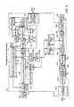
- FIG. 1shows an embodiment of a home network 10 , constructed in accordance with the invention, including a demarcation point unit (DPU) 14 located at the entry point into a home, which operates as the interface between the home network 10 and an external network 18 , such as a cable television (TV) network or the Internet.
- the DPU 14is in communication with a plurality of home-network modules (HNM) 28 , 28 ′, 28 ′′, 28 ′′′ (generally 28 ), each located in one of various rooms of the home.
- HNM 28home-network modules
- Each HNM 28is the interface between devices in a room (e.g., home entertainment devices and computer devices) and the DPU 14 .
- the home network 10does not require the rewiring of the cable TV equipment that is typically already installed in many homes for accessing the cable TV network 18 or the Internet.
- the HNMs 28communicate with the DPU 14 and with each other over standard cable equipment.
- Such cable equipmentincludes coaxial (or coax) cables 22 , splitters (generally 24 ), and cable TV outlets 26 .
- This installed cable equipmentoperates as a backbone of the home network 10 for conveying intra-room communications.
- the home network 10can operate with existing coax wiring, the principles of the invention apply also to other types of wiring, such as CAT-5 or plastic fiber.
- the home network 10operates in parallel to the cable TV services, leaving legacy cable TV signals and devices (such as set top boxes and cable modems) unaffected.
- the home network 10joins various computer devices, such as personal computers and peripherals (printer, scanner, CD etc.), and entertainment equipment, such as set top boxes (STB), televisions, videocassette recorders, personal video recorder (PVR), etc., located throughout the home into one network.
- STBset top boxes
- PVRpersonal video recorder
- the existing cable equipmentprovides an intra-room backbone for an IEEE-1394 (FireWire) network.
- HNMs 28 , 28 ′, 28 ′′, 28 ′′′ in respective rooms 30 , 30 ′, 30 ′′, 30 ′′′are connected to the home network backbone through cable TV outlets 26 .
- the home network backbone(referred to hereafter as backbone 20 ), includes a plurality of coax cables 22 that connect the cable TV outlets 26 , and thus the HNMs 28 , to the DPU 14 .
- the coax cables 22connect to the splitters 24 , which distribute the signals received from the external network 18 and from the HNMs 28 to each of the rooms 30 connected to the home network 10 .
- the DPU 14includes one of the splitters 24 ′; in another embodiment, instead of being part of the DPU 14 , that splitter 24 ′ is connected to an output of the DPU 14 .
- a residential gateway deviceis located at the demarcation point (i.e., the entry point of the coax cable to the home) to exchange signals between the external network 18 and other devices in the house, such as a cable modem or a STB.
- Embodiments of the residential gatewayprovide Internet access (e.g., cable modem, digital subscriber line (DSL)).
- Other embodimentsprovide the functionality of a set top box, of a personal video recorder, or of a tuner for multiprogramming.
- the DPU 14can be integrated into or be external to such the residential gateway device.
- Each room 30includes one or more devices 33 .
- Devices 33include, for example, digital video disc (DVD) players, videocassette recorders (VCR), game consoles, interactive televisions computers, scanners, fax machines, printers, analog televisions, digital televisions, set top boxes, stereo systems, and camcorders.
- DVDdigital video disc
- VCRvideocassette recorders
- HNM 28that connects that device 33 to the backbone 20 .
- rooms 30 , 30 ′, 30 ′′, and 30 ′′′each have devices 33 that the resident chooses to have intra-room communication capability; so, in each of these rooms an HNM 28 connects those devices 33 to the backbone 20 .
- Each HNM 28can interface with one or more different types of local buses (generally 35 ).
- the HNM 28interfaces with a local 1394-bus 35 ′, connected to an analog set-top box and a DVD player, and a local data-bus 35 ′′ (e.g., Ethernet, USB, IP), connected to analog set-top box and a personal computer.
- a local 1394-bus 35 ′connected to an analog set-top box and a DVD player
- a local data-bus 35 ′′e.g., Ethernet, USB, IP
- devices 33 in different rooms of the same local bus typecan communicate with each other over the backbone 20 , whereas devices 33 of different local bus types (e.g., 1394 and USB) do not.
- the HNM 28resides in the entertainment or data device, in other embodiments, the HNM 28 resides in a separate box.
- the HNM 28can connect to other devices 33 in the room 30 by coax cable.
- the HNM 28 in room 30also connects to the analog set-top box by coax cable 36 .
- the HNM 28is a built-in component of the set-top box.
- Each HNM 28communicates with the DPU 14 and each other HNM 28 on the backbone 20 with analog signals and converts analog signals received from the DPU 14 and the HNMs 28 into digital signals for delivery to devices 33 connected to that HNM 28 .
- an interface boxcan convert the digital signal produced by the HNM 28 into a signal that is appropriate for that legacy device.
- the HNM 28 ′communicates with the analog TV, which requires an analog signal, through the interface box 32 , which converts 1394 digital signals to audio/visual analog signals.
- devices 33 of the same protocol within a given room 30can connect to the same HNM 28 by different local buses 35 . With this arrangement, such devices 33 can communicate with devices 33 in other rooms 30 of the home.
- Devices 33 that the resident does not want to participate in intra-room communicationcan connect directly to the external network 18 without the use of the HNM 28 .
- the analog television setis connected directly to the backbone 20 without an intervening HNM 28 .
- Such devices 33continue to receive the legacy cable TV signals from the cable TV network or have broadband access to the Internet through the DPU 14 .
- each HNM 28permits those devices 33 connected to that HNM 28 to communicate with other devices 33 in different rooms 30 , to receive programming from the cable television, and to have broadband access to the Internet (e.g., through a cable modem, DSL service, and Satellite).
- a DVD disc playing in the DVD player in room 30can be viewed on the digital television in room 30 ′′ and that digital television can also receive programming from the cable television network 18 .
- computer devices in various roomscan communicate with one another using their respective HNMs 28 connected to the backbone 20 .
- the personal computer (PC) in room 30can print a document on the printer or share a file with the personal computer in room 30 ′′′, or access the Internet through a cable modem (or DSL or audio modem).
- the analog signal to and from the Internetruns over the same coax wires 22 in the house and at the same time as the intra-room communication signals (hereafter the home network signal).
- the signal received from the cable television network or Internet providerare routed to the proper electronic devices by way of the DPU 14 and the appropriate HNM 28 .
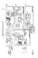
- FIG. 2shows an embodiment of the DPU 14 including a diplexer 40 , a home-network reflector unit (HRU) 44 and a splitter 24 ′′.
- the diplexer 40separates a cable TV (CaTV) signal (or satellite signal) received from the external network 18 from a home network signal received from the HNMs 28 connected to the backbone 20 .
- One input/output (I/O) port (the “L” port) of the diplexer 40transmits and receives the CaTV signal (or satellite signal) to and from the external network 18 .
- Another I/O port (the “H” port) of the diplexer 40transmits and receives the home network signal to and from HRU 44 .
- the diplexer 40also combines the CaTV (or satellite) signal received from the external network 18 resides inside the house, including the HRU 44 as part of the DPU 14 is desirable. Alternatively, if the external network 18 with the home network signal received from the HRU 44 and passes the combined signal to the splitter 24 ′ through a third I/O port (the “C” port) for subsequent transmission to the HNMs 28 over the backbone 20 .
- the “L” portuses a low-pass filter at a certain predetermined frequency, fc, and the “H” port uses a high-pass filter at the same frequency, fc.
- the frequency, feBy setting the frequency, fe, to about 900 MHz, for example, the low-pass “L” port transfers TV signals (5-860 Mhz), and the high-pass “H” port transfers the home network signal above 860 MHz. More specifically, one embodiment sets the cutoff frequency to 950 MHz to separate frequencies above 950 MHz for use by the home network signal from the CaTV signals, which are in the 5-860 MHz range.
- the frequency, fcis set to about 2100 MHz, to separate the satellite TV signals (950-2100 MHz) from the home network signal (below 950 MHz or above 2100 MHz).
- the “L” portis connected to the external network 18 and the “H” port is connected to the HRU 44 .
- the cutoff frequency, fcis set to about or below 900 MHz, and the home network signal uses frequencies below the satellite TV signals.
- the “H” portis connected to the external network 18 and the “L” port is connected to the HRU 44 .
- the HRU 44is either an unterminated or a shorted coaxial cable, which reflects the home network signal received from the diplexer 40 back to the diplexer 40 .
- a passive HRUconnect one port of a passive delay line to the H port of the diplexer 40 to improve the performance of the network 10 by avoiding signal fading.
- the other port of the passive delay lineis unterminated or shorted.
- leaving an output of the diplexer 40 unterminated or by shorting that output to groundattains reflection of the home network signal.
- FIG. 2Ashows another embodiment of the HRU 44 including a diplexer 42 , band pass (BP) filters 46 , 48 , amplifiers 50 , 52 , an RF down-converter 54 , an RF up-converter 56 and an intermediate frequency filter and amplifier unit 58 .
- the diplexer 42along with the BP filters 46 , 48 separate the upstream signal from the downstream signal.
- the upstream signalis the signal coming from the backbone 20 to the HRU 44
- downstream signalis the signal returning from the HRU 44 to the backbone 20 .
- the upstream signal coming from a transmitting HNM 28enters the diplexer 40 and passes to the internal diplexer 42 of the HRU 44 .
- the signal from the diplexer 42is band pass filtered by BP filter 46 , amplified by amplifier 50 , and RF down-converted by down-converter 54 to an intermediate frequency (IF).
- the intermediate frequencyis 630 MHz. Other different frequencies can be used without departing from the principles of the invention. Usage of the intermediate frequency simplifies the RF design, by keeping the signal, its images, and the local oscillator frequency separate from each other. Having the BPFs 46 , 48 external to the diplexer 42 simplifies the implementation of the diplexer 42 .
- the IF filter and amplifier unit 58then amplifies and band pass filters the IF signal.
- the RF up-converter 56shifts the frequency of the IF signal up to the downstream frequency band.
- the amplifier 52 and BP filter 48then amplify and filter the downstream signal.
- the amplifiers 50 , 52 with the amplification provided by the IF filter and amplifier unit 58sufficiently amplify the home network signal to improve the reach of the home network signal inside the home.
- This downstream signalthen passes through the diplexers 42 , 40 back to the backbone 20 of the home network 10 .
- the HNMs 28communicate with each other by issuing messages to the backbone 20 (i.e., the upstream signal).
- the HRU 44receives the upstream signal, amplifies and shifts the RF frequency of the upstream signal, and then returns the upstream signal with the shifted frequency to the backbone 20 as the downstream signal.
- the HNMs 28then receive the messages in the downstream signal from the backbone 20 .
- the diplexer 40combines the downstream signal with the CaTV signal (or satellite) for transmission over the in home coax wires 22 .
- the HRU 44is shown as part of the DPU 14 ( FIG. 2 ), the HRU 44 can be located separate from the DPU 14 .
- the entry point of the external network 18resides inside the house, including the HRU 44 as part of the DPU 14 is desirable.
- the entry point splittere.g., splitter 24 ′ of FIG. 1
- it is advantageous to locate the HRU 44 indoorsbecause an enclosure suitable for indoor uses is often cheaper than an enclosure suitable for outdoor use. Also, it if often difficult to deliver power to an enclosure located external to the home. Referring again to FIG.
- the HRU 44is connected to the “H” port of the diplexer 40 by a length of coax cable, thereby allowing the HRU 44 to be located at a distance from the DPU 14 .
- a coax cable having a length of up to thirty feetcan be used without a significant reduction in system performance.
- the DPU 14includes a Hybrid/Splitter 43 (also referred to as a blocking filter 43 throughout the specification) instead of the diplexer 42 and the HRU 44 .
- the Hybrid/Splitter 43is a passive filter that reflects frequencies above 950 MHz, while passing through lower frequencies.
- the magnitudes of the transfer and reflection properties of such a Hybrid/Splitter 43can be as shown in FIG. 2C : Signals traveling from S 21 to S 12 and from S 12 to S 21 have losses less than about 4 dB at frequencies between about 5 MHz-860 MHz and greater than about 20 dB at frequencies between about 950 MHz-1150 MHz.
- Signals traveling from S 31 to S 13 and from S 13 to S 31have losses greater than about 25 dB at frequencies between about 5 MHz-860 MHz and less than about 4 dB at frequencies between about 950 MHz-1150 MHz.
- Signals traveling from S 22have losses greater than about 15 dB at frequencies between about 5 MHz-860 MHz and less than about 6 dB at frequencies between about 950 MHz-1150 MHz.
- Signals traveling from S 33have losses greater than about 15 dB at frequencies between about 5 MHz-860 MHz and less than about 6 dB at frequencies between about 950 MHz-1150 MHz.
- the Hybrid/Splitter 43has a low return loss and poor isolation at frequencies above 950 MHz. At frequencies below 860 MHz, the return loss and isolation are high. Insertion loss is low at frequencies up to 860 MHz and high at frequencies above 950 MHz.
- the Hybrid/Splitter 43is constructed as a simple passive LC circuit.
- the blocking filter 43can be implemented with a diplexer having the “H” port terminated with a short circuit.
- the Hybrid/Splitter 43can be used as a replacement for any other diplexer used in the system.
- the diplexer 40is replaced with a blocking filter 43 as described with reference to FIG. 2B above.
- the splitter 24 ′is connected to the output of the blocking filter 43 .
- the HRU 44is connected to an output of the splitter 24 ′.
- the coax cable connecting the HRU 44 to the splitter 24can be about thirty feet in length.
- the main splitter 24 ′introduces additional loss between the HRU 44 and the input of splitter 24 ′. The loss is approximately 4 dB if the splitter 24 ′ is a 1-to-2 splitter, or 8 dB if it is a 1-to-4 splitter.
- a new splitter 24 ′′is installed between splitter 24 ′ and the blocking filter 43 ′.
- the splitter 24 ′′ inputis connected to the blocking filter output.
- An output of the splitter 24 ′′is connected to the input of existing main splitter 24 ′.
- the other outputis connected to the HRU 44 through an existing or newly installed coax cable.
- the HRU 44can be connected to a CaTV outlet 26 .
- a diplexer 42which is either resident within the HRU 44 or external to the HRU 44 , is connected to the outlet 26 at the “C” port of the diplexer 42 .
- the HRU 44is connected to the “H” port of the diplexer 42 .
- the “L” port of the diplexer 42can be connected to a device 33 (e.g., an analog television) or another splitter 24 . If the “L: port of the diplexer is connected to the optional splitter 24 , the outputs of the splitter can be connected to a device 33 (e.g., an analog television) and additional coax cables.
- the HRU 44can be incorporated in a device 33 .
- the HRU 44can be incorporated into a STB or a Home Media Server (HMS).
- HMSHome Media Server
- the need for an external HRUis thereby eliminated.
- the HRU 44can be incorporated in an HNM 28 . In such an embodiment, the need for an external HRU is thereby eliminated.
- the home network 10employs transmission power control.
- Each HNM 28adjusts its transmission power to such a power level that when its transmitted signal arrives at the HRU 44 , that signal has a predefined power level.
- the input power of the upstream signal arriving at the HRU 44remains constant because each HNM 28 uses an appropriate transmission power level to account for the attenuation of the signal over the backbone 20 and thereby achieves the predefined power level at the HRU 44 .
- power level of the inputted upstream signalis constant and the amplification performed by the HRU 44 is constant, the downstream signal leaving the HRU 44 is also constant.
- the upstream signal at the input to the HRU 44is ⁇ 50 dBm
- the downstream signal at its outputis ⁇ 10 dBm.
- a HNM 28can transmit at a power between ⁇ 10 dBm, if located far from the HRU 44 , and ⁇ 50 dBm if located close to the HRU 44 .
- the actual transmitted poweris determined according to the attenuation between the remote HNM 28 and the HRU 44 . For instance, if the attenuation is 10 dB, the HNM 28 should transmit ⁇ 40 dBm. If the HNM 28 is located 40 dB from the HRU 44 , that HNM 28 should transmit at a power of ⁇ 10 dBm so that the upstream signal can reach the HRU 44 with a power of ⁇ 50 dBm.
- a constant powere.g., ⁇ 10 dBm
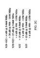
- the home network signal transmitted over the home network backbone 20is in the 960 to 1046 MHz frequency range, but other frequency bands above the CaTV signals can be used.
- the CaTV signal(including the signal from Internet providers) is in the frequency range of 5 to 860 MHz. Table 1 shows that frequencies above 960 MHz are available for use in those homes in which CaTV signals are installed. It should be noted that at frequencies greater than 1000 MHz, low quality splitters found in the home provide poor signal isolation and return loss performance.
- the home network signalis in the 5-45 MHz frequency range.
- This frequency bandis used by the U.S. cable television operators for reverse path signals, i.e., signals that the home devices 33 , such as set top boxes (STB) and cable modems (CM), transmit back to the cable provider (i.e., the head-end).
- the reverse path frequencyis located in the band from 5-65 MHz.
- Reverse channel signals transmitted to the head-endinclude the Reverse Data Channel Out Of Band (RDC OOB) signals from the STB and the Reverse Data Channel of the CM (RDC CM).
- RDC OOBReverse Data Channel Out Of Band
- RDC CMReverse Data Channel of the CM
- the head-enddetermines the actual frequencies used for the reverse channel signals and the bandwidth for each channel is small compared to the 5-45 MHz frequency range.
- the set-top boxes and cable modems in the homeuse the same programmable frequencies for the return channel.
- the head-enddetermines the frequency allocation and transmits information regarding the allocated frequencies to the devices 33 in the home.
- the head-enduses frequencies above 50 MHz.
- This communications channelat frequencies above 50 MHz, is termed the Out of Band Forward Data Channel (OOB FDC). Because frequencies above 50 MHz pass freely through the home network 10 , this OOB FDC signal carrying RDC OOB and RDC CM information passes unimpeded to the set top boxes and the cable modems connected directly (that is not through a HNM 28 ) to the coaxial cable 22 .
- OOB FDCOut of Band Forward Data Channel
- FIG. 3shows an exemplary conceptual embodiment of an implementation of the HNM 28 , which functions as bridge between the coax backbone 20 and each local bus 35 .
- the HNM 28receives a signal from a device 33 through a data port and converts that signal into a modulated analog signal over the backbone 20 , combined with the Cable TV signal.
- the HNM 28receives an analog signal over the backbone 20 and converts the analog signal into a data signal.
- the HNM 28is implemented as an IC (integrated circuit) chip set that is incorporated in an entertainment or data device, or in a standalone box.
- the backbone-side of the HNM 28includes a physical layer 90 , a media access control (MAC) layer 92 , and a network layer 94 .
- the MAC layer 92supports constant bit rate (CBR) transmission and an unspecified bit rate (UBR) transmission with CBR 96 and UBR 98 protocols, respectively.
- CBRconstant bit rate
- UBRunspecified bit rate
- the CBR protocol 96is used for the transmission of isochronous data and the UBR protocol 98 for the transmission of asynchronous data.
- the network layer 94includes a switching fabric 100 for controlling the flow of isochronous and asynchronous traffic between the backbone 20 and each local bus 35 .
- the architecture of the protocol stack on the local-bus-side of the HNM 28depends on the type of local bus.
- the local busis an IEEE 1394 bus
- the HNM 28includes a 1394 Phy layer 102 , a 1394.1 link layer 104 (with bridge functionality), and a network layer 106 that supports isochronous 107 and asynchronous 108 transmissions.
- the local busis an Ethernet bus, which has Ethernet-specific Phy and MAC layers.
- the local busis a universal serial bus (USB), which correspondingly has USB-specific Phy and data link layers.
- USBuniversal serial bus
- the bus-side of the protocol stackincludes a device-specific interface for communicating on the bus.
- the HNM 28operates as a bridge between the backbone 20 and a plurality of local buses of different types.
- the HNM 28is a bridge for 1394, 802.3, and a USB local buses.
- the HNM 28can support other types of local buses and different combinations of local bus types without departing from the principles of the invention. If the HNM 28 resides in a device, such as in a STB, the various local buses are connected directly to a local bus internal to that device.
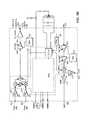
- FIG. 4shows an exemplary embodiment of the physical layer 90 of the HNM 28 , including the diplexer 110 , RF/Analog unit 112 (hereafter RF unit) and a modem 114 .
- the diplexer 110is connected to the coax outlet 26 in the room 30 and separates the CaTV signal (frequencies 5-860 MHz) from the home network signal.
- the CaTV signalincludes the broadcast video, video in demand, cable modem and all other signals that are delivered by the Cable TV operator to the home, and return path signals, like the cable modem return channel, Interactive TV etc.
- the CaTV signalcan pass to other electronic devices in the room 30 , such as a TV cable modem and an analog set-top box (STB).
- STBanalog set-top box
- the home network signalpasses to the RF unit 112 .
- the RF unit 112includes a diplexer 116 , which is connected to a downstream path 118 (here, from the backbone 20 to the local bus 35 ) and an upstream path 120 (from the local bus 35 to the backbone 20 ). From the home network signal, the diplexer 116 and filters 122 , 142 separate the downstream signal from the upstream signal. The downstream signal passes towards the local bus 35 and the upstream signal towards the backbone 20 .
- the bandpass filter (BPF) 122filters the downstream signal (lower frequencies) to remove the upstream signal and out-of-band noise.
- the downstream signalpasses through a low noise amplifier 124 and RF down-conversion circuitry 126 .
- the RF down-conversion circuitry 126converts the downstream signal to baseband frequencies.
- Embodiments of the RF down-conversion circuitry 126include an I/Q demodulator or a mixer.
- the I-channel and Q-channelpass separately to the broadband filter/amplifier unit 128 , which low-pass filters the I-channel and Q-channel separately to remove the image of the signal.
- the I-channel and Q-channelthen pass through a dual analog-to-digital (A/D) converter 129 .
- the dual A/D 129has a separate A/D converter for the I-channel and for the Q-channel.
- the digital output of the A/D converter 129enters the modern 114 .
- the modem 114includes a digital signal processing (DSP) portion 130 and a framer 132 .
- DSPdigital signal processing
- the modem 114uses an efficient modulation scheme, like QAM, multi QAM, Orthogonal Frequency Division Multiplexing (OFDM) or Discrete Multitone (DMT).
- the backbone 20supports 100 Mbps bit rate. If, for example, the modem 114 uses QAM 256 (8 bits per symbol), only 12.5 MHz (100/8) of bandwidth is required. The use of efficient bandwidth modulations achieves higher data rates for a specific frequency band produces less cross talk between potentially interfering signals.
- Another advantageis that the modem 114 enables the home network 10 to coexist with pre-existing low-quality splitters often found in the cable networks of the home. Such splitters are frequency limited—at frequencies above 1000 MHz the performance of such splitters degrades significantly. Reflections can occur at the splitter, resulting in inter-symbol interference to the home network signal.
- the upstream path 120passes from the modem 114 to the diplexer 116 through a dual D/A converter 134 , a baseband filter/amplifier unit 136 , RF up-conversion circuitry 138 , an amplifier 140 , and a band-pass filter 142 .
- the DSP 130On the upstream path 120 , the DSP 130 generates one or two output words corresponding to one or two D/A converters 134 , depending upon the embodiment of the RF up-conversion circuitry 138 .
- Embodiments of the RF up-conversion circuitry 138include an I/Q modulator or a mixer. If I/Q modulation is used in the RF up-conversion circuitry 138 , then two output channels are implemented, with two D/A converters 134 . If the mixer is used, then only one D/A converter 134 is needed.
- the analog baseband signal generated by the D/A converters 134passes through baseband filters 136 and then is up-converted by the RF up conversion circuitry 138 to the upstream frequency band.
- the power amplifier 140amplifies the RF up-converted signal and the bandpass filter 142 filters the signal and the diplexer 116 combines the upstream signal with the CaTV signal for transmission over the home coax backbone 20 .
- the gain of the amplifiers 124 and 140are programmable, and the modem DSP 130 sets this gain.
- the RF circuitry of the HNM 28can also be used to provide the HRU functionality.
- the RF circuitry 112 ′ on the left side of the figureprovides the traditional HNM 28 functionality.
- the circuitryincludes a circulator 111 .
- the downstream signalpasses through the circulator 111 to a low noise amplifier 124 ′ and RF conversion circuitry 127 .
- the RF conversion circuitry 127converts the downstream signal to a baseband frequency f1.
- the RF-conversion circuitry 127includes an I/Q demodulator, a phase lock loop, and a mixer.
- the downstream analog signalpasses through the mixer of the RF conversion circuitry 127 to a A/D converter 129 ′ through another BPF 117 ′.
- the digital output of the A/D converter 129 ′is forwarded to DSP circuitry 130 where the appropriate signal processing is accomplished.
- the RF conversion circuitry 127is frequency agile. That is, the frequencies used in the upstream 120 and downstream paths 118 are controllable. The frequencies are determined by software associated with a local oscillator (not shown), which is part of the RF conversion circuitry 127 , and the digital frequency shifter of the modem DSP 130 .
- the upstream path 120passes from the modem 114 (not shown) to the circulator 111 through a pair of D/A converters 134 ′, a pair of low pass filters 137 , the RF conversion circuitry 127 , an amplifier 140 ′, and another BPF 117 .
- the DSP 130 circuitryOn the upstream path 120 , the DSP 130 circuitry generates two output words. One word is sent to each of the of the two D/A converters 134 ′.
- the analog baseband signals generated by the D/A converters 134 ′passes through low-pass filters 137 and then is up-converted by the RF conversion circuitry 127 .
- the power amplifier 140amplifies the RF up-converted signal and the diplexer 116 combines the upstream signal with the CaTV signal for transmission over the home coax backbone 20 .
- the gain of the amplifiers 124 ′ and 140 ′is programmable, and the modem DSP 130 sets this gain.
- the HNM 28is designed to function as a regular HNM 28 , the HNM 28 transmits data in the upstream frequency band and receives data in the downstream frequency band. When the HNM 28 is not transmitting data, it only receives the reflected signal in the downstream frequency band.
- the right half of FIG. 4Adepicts circuitry 112 ′′ that is substantially similar to the circuitry 112 ′.
- the circuitry 112 ′′provides the HRU functionality. When functioning as the HRU 44 , the circuitry 112 ′′ transmits data in the downstream frequency and receives data in the upstream frequency.
- the circuitry 112 ′′includes a circulator 111 and a bandpass filter (BPF) 117 .
- BPFbandpass filter
- the upstream signalpasses through the circulator 111 to a low noise amplifier 124 ′ and RF conversion circuitry 127 .
- the RF conversion circuitry 127converts the upstream signal to a baseband frequency f2, which is different from baseband frequency f1 described above.
- the RF-conversion circuitry 127includes an I/Q demodulator, a phase lock loop, and a mixer.
- the upstream analog signalpasses through the mixer of the RF conversion circuitry 127 to a A/D converter 129 ′ through another BPF 117 ′.
- the digital output of the A/D converter 129 ′is forwarded to DSP circuitry 130 where the appropriate signal processing is accomplished.
- the downstream path 118passes from the DSP circuitry 130 to the circulator 111 through a pair of D/A converters 134 ′, a pair of low pass filters 137 , the RF conversion circuitry 127 , an amplifier 140 ′, and another BPF 117 .
- the DSP 130 circuitryOn the upstream path 120 , the DSP 130 circuitry generates two output words. One word is sent to each of the of the two D/A converters 134 ′.
- the analog baseband signals generated by the D/A converters 134 ′passes through low-pass filters 137 and then is down-converted by the RF conversion circuitry 127 .
- the power amplifier 140amplifies the RF down-converted signal and the diplexer 116 combines the downstream signal with the CaTV signal for transmission over the home coax backbone 20 .
- the gain of the amplifiers 124 ′ and 140 ′is programmable, and the modem DSP 130 sets this gain.
- the circuitry 112 ′′when functioning as the HRU 44 , transmits data in the downstream frequency and receives data in the upstream frequency. When the circuitry 112 ′′ does not transmit its own data, the circuitry 112 ′′ reflects the received signals to the coax backbone 20 in the downstream frequency.
- This functionalitycan be achieved by analog amplifying and shifting in frequency, as described above with reference to FIG. 4 .
- analog and digital processingcan be combined, as described with reference to FIG. 4A . In this method, the received signal (at the upstream frequency) is frequency down converted, analog to digital converted, and then amplify and frequency shifted digitally, before being converted back to analog by the digital to analog converters.
- the RF circuitry of FIG. 4Acan be incorporated into a chip.
- the chipcan include the band pass filter 117 , a wideband BPF 117 ′, the low noise amplifier 124 ′, the RF conversion circuitry 127 , the low pass filters 137 , and the power amplifier 140 ′. Additionally the chip includes a receive automatic gain control circuit (AGC) 125 , a first D/A circuit 131 , a transmit driver module 141 , and a second D/A circuit 143 .
- the chipincludes a receive port 151 , which is in communication with the LNA 124 ′, and a transmit port 153 , which is in communication with the transmit driver module 153 .
- the chipalso includes a first output port 155 and an optional output port 155 ′.
- the first output port 155provides the output of the BPF 117 to, for example, the DSP circuitry 130 .
- the optional output port 155 ′provides the output of the wideband BPF 117 ′ to external circuitry, as described in more detail below.
- the chipalso includes two DSP input ports 157 , which provide the LPFs 137 with the signals from, for example, the DSP circuitry 130 .
- a signalis received from the coax backbone 20 at receive port 151 .
- the signalis amplified, frequency converted and filtered as described above. After filtering, the received signal is provided to, for example, the DSP circuitry 130 via output port 155 .
- the signalis returned to the LPFs 137 via DSP input ports 157 .
- the received signalsare frequency converted and combined as described above.
- the combined signalis then amplified by power amplifier 140 ′.
- the driver module 141receives the amplified signal transmits the signal back out on the coax backbone 20 through transmit port 153 .
- the gain of the AGC circuitry 125 and the power amplifier 140 ′is controlled by the DSP circuitry 130 .
- D/A converters 131 and 143receive a digital signal from the DSP circuitry 130 that is indicative of the amount of gain the amplifiers 125 and 140 ′ are to provide. In response, the D/A converter the digital signal to an analog signal and thus control the gain of the amplifiers 125 and 140 .
- the chipcan be configured to function as a stand alone HRU 28 .
- a signalis received at the receive port 151 .
- the signalis amplified, frequency converted to an intermediate frequency, and filtered.
- the output of the wideband BPF(e.g., 120-85 MHz) is provided at the optional output port 155 ′.
- the signal at the optional output port 155 ′is mixed by a mixer 163 .
- a PLL 165provides a mixing signal to the mixer 163 at a higher frequency than that of the output of the BPF 155 ′.
- the PLL 165can provide a signal at substantially 1155 MHz.
- the mixed signalis provided to a surface acoustic wave device (SAW) 167 for further signal manipulation.
- the output of the SAW 167is provided to the power amplifier 140 for amplification and transmission to the coax backbone 20 , as described above.
- SAWsurface acoustic wave device
- analog and digital signal processing methodsare combined to provide the RF unit 112 ′ functionality with an increased frequency agility range. For example, frequency agility of 55 MHz to 1050 MHz is achievable.
- the RF unit 112includes a diplexer 116 ′′ or a hybrid/splitter 43 , which is connected to a downstream path 118 ′′ (here, from the backbone 20 to the local bus 35 ) and an upstream path 120 ′′ (from the local bus 35 to the backbone 20 ).
- the downstream signalpasses towards the local bus 35 and the upstream signal towards the backbone 20 .
- the RF BPF 122 ′′filters the downstream signal (lower frequencies) to remove the upstream signal and out-of-band noise.
- the downstream signalpasses through a low noise amplifier 124 ′′ and RF conversion circuitry 127 ′′.
- the RF conversion circuitry 127 ′′converts the downstream signal to baseband frequencies and the upstream frequencies from the baseband frequencies.
- the RF conversion circuitry 127 ′′includes a downstream mixer 500 , an upstream mixer 504 , and a first digital synthesizer 508 .
- the mixers 500 , 504 and the first synthesizer 508function to convert the signals to and from the intermediate frequency in the downstream 118 ′′ and upstream 120 ′′ paths, respectively.
- the signalis passed through IF BPF 512 . If the HNM 28 is functioning as a HRU and HNM, then signal is passed through an amplifier 516 (e.g., a low noise amplifier), and in turn to second IF BPF 520 . After filtering, the IF signal is upconverted to the upstream frequency by the RF conversion circuitry 127 ′′. If the HNM 28 is not functioning as an HRU HNM, the IF signal is communicated from the IF BPF 512 to an IQ demodulator 254 for a second stage of frequency adjustment. The IQ demodulator 524 is in communication with a second digital synthesizer 528 .
- an amplifier 516e.g., a low noise amplifier
- the output of the IQ demodulatoris passed to A/D converters (not shown).
- the IF signalsare received from D/A converters (not shown) by an IQ modulator 532 , which provides a first stage of up-conversion.
- the IQ modulator 532is also in communication with the second digital synthesizer 528 .
- FIG. 5shows two embodiments of the modem 114 , including the DSP 130 and the framer 132 .
- Signalstake two paths through the modem 114 ; the downstream path 118 from the dual A/D converter 129 to the MAC 92 through the framer 132 and the upstream path 120 from the framer 132 to the dual D/A converter 134 .
- I/Q modulationoccurs at the RF unit 112 .
- This embodimentincludes an I/Q compensation block 144 (shown in phantom) that compensates digitally for different I/Q modulation imperfections, such as local oscillator leakage, I/Q phase and amplitude imbalance, and DC signal components.
- the I/Q compensated signalpasses to receiver front-end circuitry 146 , which includes a match filter and an interpolator (both not shown).
- the match filterfilters noise and other undesired out-of-band signals.
- the interpolatoroutputs a signal that is sampled at an integer multiple of the received sample rate based on timing recovery information received from a timing VCO block 148 and a timing PLL block 150 provide.
- the timing recoveryis useful because the A/D converter 129 samples the downstream signal at its particular sampling frequency, which approximates but may not equal the symbol rate of the HNM 28 that transmitted the signal.
- I/Q modulationoccurs at the DSP 130 of the modem 114 (because the RF unit 112 uses a standard mixer; thus, this embodiment has no I/Q compensation block 144 .
- the receiver front-end 146 of this embodimentincludes a down-converter block and low-pass filter (both not shown) to perform the I/Q demodulation.
- the output of the receiver front-end 146passes to a burst AGC block 152 , which provides digital gain control per burst to optimize the signal level at the input to the equalizer 154 .
- the signalpasses to a decision feedback equalizer (DFE) 154 .
- the DFE 154includes a feed forward equalizer (FFE) 156 and a decision feedback filter (DFF) 158 .
- FFEfeed forward equalizer
- DFFdecision feedback filter
- the DFE 154includes a rotator 160 , which is applied at the output of the FFE 156 .
- a carrier recovery PLL 162sets the correction frequency of the rotator 160 .
- the output of the rotator 160 minus the output of the DFF 158enters a slicer circuit 164 to make a decision on the received symbol.
- the error signal 166is equal to a distance between the decided symbol and the input to the slicer circuitry 164 .
- the error signal 166gives an indication to the amount of noise and the quality of the received signal and decisions.
- the error signal 166is also used for the adaptation of the equalizers during packet receiving.
- FECde-forward error correcting
- the framer 132receives data bits from the MAC 92 , which frames the bits.
- a mapper 170maps the encoder-framed bits to generate the transmitted QAM symbols.
- a transmitter front-end 172processes the QAM symbols.
- the transmitter front-end 172includes a pulse shaper 174 , a digital power gain adjuster 176 for fine tuning the transmitted power, and a clipper 176 to reduce the peak-to-average ratio of the transmitted signal to relax RF transmitter requirements.
- An interpolator 180synchronizes the transmitted symbol rate with the symbol rate of the master HNM 28 .
- the modulator timing VCO loop 182performs the synchronization.
- the signal leaving the interpolator 180is a complex signal, that is, the signal is made of two streams of data (a real channel and an imaginary channel).
- the DSP 130is implementing I/Q demodulation, the DSP 130 includes an I/Q frequency up-converter 184 to create a real signal.
- An inverted-sinc filter 186then shapes the resulting I/Q signal band and delivers the shaped signal to the D/A converter 134 .
- the I/Q frequency up-converter 184is not used.
- the signal from the interpolator 180remains complex and the dual D/A converter convert the two (real and imaginary) signal streams into two analog channels (I and Q).
- a transmitter I/Q compensator 188is employed to handle RF imperfections.
- the DSP portion 130 of the modem 114also includes a preamble detector and channel estimation block 190 (hereafter preamble detector), which is communication with the I/Q compensation block 144 (if any), the receiver front-end 146 , a cycle start detector 192 , and the burst AGC block 152 .
- the preamble detector 190also controls the gain of the amplifiers 124 and 140 of the RF unit 112 to provide power control, as described above.
- the preamble detector 190provides channel estimations, RF imperfection estimations, and synchronization information for the PLL loop 150 .
- the preamble detector 190initializes the DFE 154 for each burst.
- preamble detector 190Other functions include detecting an existing burst in the downstream path 118 , distinguishing between types of bursts (described below), and detecting a cycle start signal. Depending upon the type of burst detected, the modem 114 adopts a different behavior.
- the MAC ( FIG. 3 ) layer 92controls the transmission protocol (hereafter MAC protocol) by which the HNMs 28 communicate with each other over the coax backbone 20 .
- MAC protocoltransmission protocol
- one of the HNMs 28 connected to the coax backbone 20is designated as a master HNM 28 .
- such designationcan occur by manually configuring that one HNM 28 to operate as the master HNM 28 .
- the HNMs 28elect the master HNM 28 .
- Functionality of the master HNM 28includes: 1) assigning addresses to each of the HNMs 28 and devices in the home network; 2) synchronizing the HNMs 28 ; 3) managing isochronous and asynchronous transmissions over the backbone 20 to avoid collisions between transmitting HNMs 28 ; 4) allocating bandwidth to the HNMs 28 ; and 5) registering new HNMs 28 .
- a master HNMthat is incorporated in or in communication with a STB (or other device that has access to the cable head-end) operates as a window into the home network through which someone at the cable head-end can monitor and diagnose the operation of the home network 10 .
- Communication on the coax backbone 20 between HNMs 28is isochronous or asynchronous, in accordance with the MAC protocol.
- the HNMs 28transmit isochronous and asynchronous bursts over the backbone 20 .
- Each bursthas a predefined structure (described below) that encapsulates one or more packets.
- the header of the packetsincludes the destination address of the target device for that packet—each packet has its own destination).
- the data in such packetsconvey the messages (i.e., the meaning of the communications).
- the devices 33 on the local buses 35produce and send the packets to the appropriate HNM 28 to be prepared into bursts.
- a single burstcan include packets that originate from more than one device 33 on a local bus 35 or that are targeted to more than one device 33 on a local bus 35 .
- the MAC protocolensures that bursts transmitted by different HNMs 28 over the backbone 20 do not collide, or if collisions do occur because of errors or noise over the backbone 20 , the home network can recover and resume normal operation.
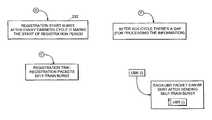
- the MAC protocolsupports at least seven types of bursts: 1) cycle start bursts; 2) data bursts; 3) registration start bursts; 4) registration bursts; 5) fairness cycle start bursts, 6) empty bursts, and 7) self-train bursts, each described in more detail below. Only the master HNM 28 issues cycle start, fairness cycle start, and registration start bursts.
- the cycle start burstindicates the start of an isochronous cycle and of a transmission cycle (described below).
- Each cycle start burstcarries CBR data of the master HNM 28 .
- the CBR data in the cycle start burstcan include management data, an identity of each HNM 28 that is going to transmit a data burst during the upcoming CBR period 228 , and a transmission order for the HNMs 28 to follow during the CBR period 228 .
- the other HNMs 28 in the home network 10synchronize to this cycle start burst.
- Fairness cycle start burstsmark the start of a fairness cycle (and a UBR period). Registration start bursts indicate a beginning of a registration period that is available for a new HNM 28 to use, as described below.
- Any HNM 28can issue data bursts, empty bursts, and self-train bursts.
- Data burstscarry data and management information.
- Empty burstscarry no data.
- a HNM 28transmits an empty burst when it has no data to transmit during its allotted time.
- the master HNM 28transmits an empty burst if another HNM 28 does not use its allotted time (and does not issue an empty burst).
- Self-train burstsoperate to calibrate the HNM 28 to the transmission characteristics of the home network.
- HNMs 28 other than the master HNM 28issue registration bursts to register with the master HNM 28 , and thus with the home network 10 .
- the registering HNM 28can request a guaranteed bandwidth and indicate the amount of bandwidth desired.
- FIG. 6shows an exemplary embodiment of the structure of each burst 200 that the HNMs 28 transmit over the coax backbone 20 .
- Each burst 200is a sequence of segments that includes a preamble 202 (having a periodic preamble 210 and an aperiodic preamble 212 ), a Phy header 204 , data 206 , and a postamble 208 .
- the preamble 202signifies the start of the burst 200 and the type of burst 200 .
- the preamble 202enables the modem 114 of the HNM 28 to synchronize the carrier and timing loops 162 , 150 , respectively, and the equalizers 156 , 158 to the transmitted burst 200 .
- the preamble 202also enables the setting of the gains of the analog amplifiers 124 , 140 in the RF unit 112 .
- the periodic preamble 210is a predetermined sequence that enables the modem 114 within the HNM 28 to achieve carrier sense, carrier and timing synchronization, received-power level estimation, and initial channel estimation.
- the length of the periodic preamble 210indicates the type of burst. The length is determined by the number of times a sequence of symbols (e.g., 32 symbols) is repeated. For example, in one embodiment, if the 32-symbol sequence is repeated 4 times then the burst is a data burst, 6 times means that the burst is a cycle start burst, 8 times indicates a fairness cycle start burst, and 10 times indicates a registration start burst.
- the pattern of symbols in the periodic preamble 210can also be used to indicate the type of burst.
- two different burst typescan have the same periodic preamble length, but be distinguished by different symbol patterns (e.g., inverting the sign of the signal for every other repeated symbol sequence).
- the periodic preamble of the empty bursthas a 32 symbol sequence that is repeated four times, which is the same length as the periodic preamble of the data burst.
- the self-train burstthe 32-symbol sequence is repeated 8 times, which is the same length as the periodic preamble of the cycle start burst.
- the signalternates for every other repeated symbol sequence, which distinguishes these bursts from the data and cycle start bursts (which do not use an alternating sign), respectively.
- bursts that require channel estimation and bursts that do notbursts that require the channel estimation by the receiving HNM 28 include data bursts, cycle start bursts, fairness start bursts, registration bursts, and registration start bursts.
- Each of these burst typeshas a preamble 202 of a fixed length; that is, cycle start bursts have a preamble of a first fixed length, fairness start bursts have a preamble 202 of a second fixed length, etc.
- the distinguishing of burst types by the length of the preamble 202assures that the receiving HNM 28 achieves real-time performance without the need for extended complexity and buffering.
- encoding the burst type by the periodic preamble lengthis more advantageous than embedding the burst type in the header, as is the usual practice with lower rate systems. Encoding the burst type by the periodic preamble length rather than embedding the burst type in the header avoids a time consuming process of extracting the data embedded in the header to determine the burst type.
- Bursts that do not require channel estimationinclude empty (or null) bursts and self train bursts, which in general have a shorter preamble 202 than the other types of bursts.
- the periodic preamble 210 of the preamble 202 for these burstshave an alternating sign (signals of the odd periods are the inverse of signal of the even periods).
- this type of preamble 202is useful for burst type identifications.
- the modem 114uses the predetermined aperiodic preamble 212 , which is a pseudo-random sequence, to refine the channel estimation and to initialize the modem equalizers 154 , 156 .
- the Phy header 204includes the parameters that are required by the DSP 130 and FEC 132 to decode the bursts (i.e., a scrambler seed, FEC parameters, interleaver parameters, constellation sizes, etc.). In some embodiments, the Phy header 204 also includes the source address of each device 33 originating the burst. In one embodiment, the Phy header 204 conveys 36 bits of information on 18 QPSK (Quadrature Phase Shift Keying) symbols.
- QPSKQuadrature Phase Shift Keying
- the data 206carries the QAM symbol data.
- the constellationis the same for each HNM 28 (when transmitting), except when the HNM 28 is transmitting a registration burst. (Registration bursts are always QPSK, which is the default constellation size for new HNMs 28 requesting to join the home network 10 .)
- the postamble 208is a predefined sequence of BPSK (Binary Phase Shift Keying) symbols that the modem 114 uses (along with any gap that follows the burst 200 ) to recognize as the end of the burst 200 .
- BPSKBinary Phase Shift Keying
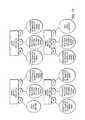
- FIG. 7shows an embodiment of an exemplary sequence 220 of bursts, separated by transmission gaps, produced by four HNMs 28 (HNM 0 , HNM 1 , HNM 2 , and HNM 3 ) on the coax backbone 20 in accordance with the MAC protocol.
- HNM 0 , HNM 1 , HNM 2 , and HNM 3HNMs 28
- Transmission of the bursts over the backbone 20occurs as a sequence of cycles. Each cycle carries information that enables the HNMs 28 to recover timing and other parameters accurately for the successful receiving and transmitting of bursts.
- the sequence of cyclesincludes three types of communication cycles, 1) transmission cycles 222 , 2) fairness cycles 224 , and 3) ACK cycles 226 , and four types of periods, 1) constant bit rate (CBR) periods 228 , 2) unspecified bit rate (UBR) periods 230 , 3) registration periods 232 , and 4) ACK periods 226 .
- CBRconstant bit rate
- URRunspecified bit rate
- Each transmission cycle 222starts when the master HNM 28 transmits a cycle start burst and ends before the master HNM 28 transmits the next cycle start burst.
- Each transmission cycle 222has a predetermined duration (e.g., approximately 1 ms) and starts with a CBR period 228 . During this CBR period 228 , each HNM 28 that has been allocated bandwidth by the master HNM 28 transmits one CBR burst.
- CBR burstscan include one or more CBR packets aggregated together and transmitted during the CBR period.
- Each HNM 28 that has been allocated time within the CBR period 228transmits one burst, but the size (or length) of that burst depends upon the amount of bandwidth allocated to that HNM 28 and upon the amount of data ready for transmission in that particular transmission cycle. If at a particular transmission, the HNM 28 does not have any data ready for transmission, the HNM 28 transmits an empty (or null) burst. This empty burst notifies the next HNM 28 in the transmission order that the next HNM 28 can now transmit during the CBR period 228 .
- the HNMs 28transmit bursts over the backbone 20 in an order predefined by the master HNM 28 .
- the transmission order during each CBR period 228is HNM0 (the master HNM) followed by HNM1 and then by HNM3.
- HNM2has no allocated bandwidth during the CBR period 228 .
- the master HNM 28can change the amount of allocated bandwidth and the order of transmission, such as when a new HNM 28 registers for guaranteed quality of service.
- the master HNM 28communicates such changes to the other HNMs 28 in the data field 206 of the cycle start burst.
- a UBR period 230 or a registration period 232 and/or an ACK period 226follows the CBR period 228 .
- the UBR period 230is part of a fairness cycle 224 , as described below.
- each HNM 28can send a self-calibration (or training) burst before sending a UBR burst.
- a UBR burstis a burst that is transmitted during the UBR period 230 .
- a fairness cycle 224represents the time over which every HNM 28 transmits one UBR burst over the coax backbone 20 . (If a HNM 28 has no data to transmit, the HNM 28 transmits a null burst in its allotted time.)
- the fairness cycle 224can span one or more transmission cycles 222 . Accordingly, during a fairness cycle 224 , UBR periods 230 are interleaved with CBR periods 228 .
- each fairness cycle 224begins with a UBR burst from the master HNM 28 (called a fairness start burst) and completes after all of the other registered HNM 28 transmits a UBR burst.
- the HNMs 28transmit the UBR bursts according to a certain order, starting with the master HNM 28 (here, HNM 0 ).
- the UBR burstsdo not disturb the synchronization of the transmission cycle; that is, transmission cycles 222 and, thus, CBR periods 228 , occur regularly (with some jitter, described below), even if each registered HNM 28 has not yet transmitted an UBR burst.
- Jitteroccurs when one of the HNMs 28 is presently transmitting a UBR burst while the start of a new transmission cycle 222 is due to begin. Instead of starting the new transmission cycle 222 , the HNM 28 is permitted to complete the UBR burst, which extends the present transmission cycle 222 beyond the predefined transmission cycle period. Jitter is the measure of the amount of time that the UBR period extends beyond the expected end of the transmission cycle 222 (i.e., start of the next CBR period 228 ).
- the master HNM 28transmits a registration start burst to initiate a registration period 232 , which extends for a predefined period. (The registration start burst marks the end of the fairness cycle 224 .)
- the master HNM 28determines when to start the registration period 232 .
- a registration period 232can occur as often as after each fairness cycle 224 .
- the registration period 232occurs less frequently, such as after a plurality of fairness cycles 224 .
- the registration period 232can extend beyond the end of the current transmission cycle 222 , thus delaying the start of the next transmission cycle 222 .
- the registration period 232is available for use by new HNMs 28 (i.e., HNMs 28 that have been added to the home network and have not yet participated in network communications).
- new HNMs 28register with the master HNM 28 , transmit a self-train burst to adapt the Phy parameters, and if already calibrated, transmits a registration burst.
- An HNM 28 that transmits a registration burstsexpects to receive from the master HNM 28 , in a subsequent cycle start burst, a response that includes a new identity for the registering HNM 28 and a position in the UBR transmission order in which to transmit UBR bursts.
- HNM 28During a given registration period 232 , more than one HNM 28 might attempt to register with the master HNM 28 . Accordingly, collisions between HNMs 28 can occur. However, the number of HNMs 28 participating in any given registration period 232 is typically few; thus, the likelihood of collisions on the home network 10 is generally low. Also, colliding HNMs 28 that do not successfully register during the present registration period 232 retransmit the registration request during a subsequent registration period 232 . Each HNM 28 independently and randomly determines the number of registration cycles to wait before retransmitting a registration request. This random and independent retransmission reduces the likelihood that the colliding HNMs 28 will collide again. Further, each HNM 28 that successfully registers during a given registration period 232 does not communicate during subsequent registration periods (subsequent transmissions by successfully registering HNMs 28 occur during the time slot allocated to that HNM 28 ).
- the master HNM 28receives the registration bursts, if any, from new HNMs 28 .
- the master HNM 28responds to one of the registration bursts with a cycle start burst that includes a master management message within the data field 206 of the cycle start burst.
- the master management messageindicates to the registering HNM 28 where that HNM 28 appears in the transmission order during the CBR period 230 and, if required, the amount of bandwidth that has been allocated to the HMN 28 .
- the master HNM 28If the master HNM 28 receives more than one registration request, the master HNM 28 responds to only one of the registration requests, and the other registering HNMs 28 retransmit during a subsequent registration period as described above.
- the master HNM 28identifies the HNM 28 to which the master is responding in the Phy header 204 of the cycle start burst.
- the master HNM 28transmits an ACK burst, marking the start of an ACK period 226 (or cycle).
- the first ACK bursti.e., ACK0
- the registration start burstmarks the start of the ACK period 226 .
- each HNM 28starting with the master HNM 28 , transmits an ACK corresponding to the UBR bursts during the previous fairness cycle 224 .
- ACK burstsare used for UBR traffic.
- Each HNM 28sends an acknowledge message (ACK) for each burst that the HNM 28 receives. If the transmitting HNM 28 does not receive an acknowledgement from one of the destinations, it retransmits the packets.
- ACKacknowledge message
- Using acknowledgment messagesimproves the performance of the home network 10 in cases of noise that corrupt some burst traffic.
- Each burstis an aggregation of packets destined for one or more destinations. If an ACK is not received from one or some of the destinations in the burst, the messages corresponding to the unacknowledged packets are retransmitted.
- a gapcan appear in the communications on the coax backbone 20 when the master HNM 28 is still processing the last ACK burst of the ACK period 226 . Then, the master HNM 28 marks the end of the ACK cycle and the start of the next fairness cycle 224 by transmitting a UBR burst. If the expected time for the start of the next transmission cycle 222 arrives, the master HNM 28 transits a cycle start burst.
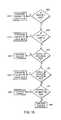
- FIGS. 8A-8Bshow an embodiment of a process by which the master HNM 28 controls communication on the coax backbone 20 .
- the master HNM 28sends (step 240 ) a cycle start burst onto the backbone 20 .
- the cycle start burstcan include master management data, an identity of each HNM 28 that is going to transmit a data burst during the upcoming CBR period 228 , and a transmission order for the HNMs 28 to follow during the CBR period 228 .
- the listed identitiesare of those HNMS 28 that have requested from the master HNM 28 a guaranteed bandwidth.
- the cycle start burstincludes information regarding the HNMs 28 that are to transmit a UBR burst during the transmission cycle, such as a transmission order.
- the cycle start burstalso includes the CBR transmission order information.
- the master HNM 28monitors (step 242 ) the backbone 20 for CBR bursts.
- the master HNM 28determines that the CBR period 228 has ended, and if a previous ACK cycle 224 has ended, the master HNM 28 issues (step 246 ) a UBR burst to start a new ACK cycle.
- the master HNM 28monitors (step 248 ) the backbone 20 for subsequent UBR bursts.
- the master HNM 28maintains (step 250 ) a timer to determine when the present transmission cycle 222 is to end. When the timer indicates the end of the transmission cycle 222 , the master HNM 28 starts the next CBR period 228 by issuing (step 252 ) a cycle start burst. Before issuing the cycle start burst, the master HNM 28 waits for any burst in progress to complete.
- the master HNM 28determines (step 254 ) that the current fairness cycle 224 has ended, the master HNM 28 transmits (step 256 ) a registration start burst to initiate a registration period 232 .
- the master HNM 28can skip one or more fairness cycles 224 before initiating the registration period 232 .
- the master HNM 28receives (step 258 ) zero, one or more registration requests.
- the master HNM 28replies (step 260 ) to one registration request during the next CBR period.
- the master HNM 28maintains (step 266 ) a timer to determine when the registration period ends. When the timer indicates the end of the registration period, the master HNM 28 sends (step 268 ) an ACK burst to mark the start of the ACK cycle. During the ACK cycle, the master HNM 28 determines (step 270 ) when the present transmission cycle ends and issues (step 272 ) a cycle start burst to start the next CBR period 228 . In one embodiment, the master HNM 28 waits until the ACK cycle ends before sending the cycle start burst. Also during the ACK cycle, the master HNM 28 monitors (step 274 ) the backbone 20 for ACKs from the other HNMs 28 .
- the master HNM 28Upon detecting completion of the ACK cycle, including waiting for an ACK for its own UBR burst (i.e., if the ACK was requested in that UBR burst), the master HNM 28 issues (step 276 ) a UBR burst (a fairness cycle start burst) to start a new fairness cycle or a cycle start burst to start a new transmission cycle if the expected time to start a new transmission cycle has arrived.
- a UBR bursta fairness cycle start burst
- FIG. 9shows an embodiment of a process by which each HNM 28 in the home network, other than the master HNM 28 , communicates over the coax backbone 20 .
- the HNM 28receives a cycle start burst and determines from the cycle start burst its positions in the transmission orders for CBR and UBR and its allocated amount of bandwidth.
- the cycle start burstoperates to synchronize communications between the HNM 28 and the master HNM 28 .
- the HNM 28monitors (step 282 ) the backbone 20 for CBR bursts, and after waiting for its own allotted time in the CBR transmission order, if any, transmits (step 284 ) a CBR burst.
- the HNM 28determines when the CBR period is over (each HNM 28 can determine the list of HNMs 28 participating in the CBR period from the information provided by cycle start burst).
- the HNM 28determines (step 286 ) whether it can transmit a UBR burst. To be enabled to transmit a UBR burst, in one embodiment the HNM 28 requires (step 288 ) a grant from the HNM 28 that precedes it in the transmission order. After transmitting the UBR burst, the grant passes (step 290 ) to the next HNM 28 in the UBR transmission order. In another embodiment, the HNM 28 awaits its turn (step 288 ′) to transmit the UBR burst by monitoring the backbone 20 and counting the number of UBR bursts that were transmitted since the start of the current fairness cycle 224 .
- the HNM 28detects an ACK burst (or in one embodiment a registration start burst) on the backbone 20 , marking the start of an ACK cycle.
- the HNM 28determines (step 294 ) when to transmit the ACK based on its position in the transmission order. If the HNM 28 has an ACK to transmit (depending upon whether it received a UBR requesting an ACK during the previous fairness cycle), the HNM 28 transmits the ACK; otherwise the HNM 28 transmits an empty (null) burst.
- the HNM 28can make this determination by monitoring the backbone 20 for ACK bursts or by waiting to receive a grant from the HNM 28 immediately preceding in the UBR transmission order.
- FIG. 10shows an embodiment of a process by which a new HNM 28 becomes part of home network 10 .
- the new HNM 28Upon detecting (step 296 ) a registration start burst, the new HNM 28 issues (step 298 ) a Self_Train Burst (for calibrating its PHY) or a registration request. If the new HNM 28 does not receive a reply indicating that the master HNM 28 has registered the new HNM 28 , the new HNM 28 transmits (step 298 ) another registration request in a subsequent registration period. The new HNM 28 continues to transmit registration requests during subsequent registration periods until the new HNM 28 becomes registered. In one embodiment, the new HNM 28 randomly selects how many registration periods to skip before retransmitting the registration request. After becoming registered, the new HNM 28 transmits bursts during the UBR period as described above.
- the home networkincludes a plurality of local buses 35 each connected to the coax backbone 20 network by an HNM 28 .
- One of the HNMs 28is the master HNM 28
- the local bus 35 that is connected to the master HNM 28is the prime bus. If the same HNM 28 connects multiple local buses 35 to the coax backbone 20 , each local bus 35 is of a different type (e.g., 1394, Ethernet, USB); if that HNM 28 is the master HNM 28 of the home network 10 , then each of such local buses 35 is deemed to be the prime bus (of its particular type).
- FIG. 11shows one embodiment of the home network 10 , in which the backbone 20 connects four IEEE 1394 local buses through different HNMs 28 .
- each HNM 28 shownoperates as a 1394-to-coax backbone bridge between the backbone 20 and the 1394 local bus connected to that HNM 28 .
- Devices 33 that are connected to one of the 1394 busesare referred to as 1394 devices or nodes.
- the backbone 20appears as a ring, this is for purposes of showing that the HNMs 28 are connected to the backbone 20 , and not intended to show that the backbone 20 operates as a ring network.
- each bridgeoperates according to the IEEE 1394.1 standard.
- the bridgeemulates the plurality of 1394 buses as a single bus so that nodes connected to these 1394 local buses can communicate with each other as though on the same 1394 bus (i.e., using the short haul 1394 protocol).
- the Link layer 104uses the asynchronous routing table to determine whether the destination identifier of an asynchronous packet is on a remote bus (other than the local bus from which the packet originates). If the destination is on a remote bus, the Link layer 104 sends an ACK_pending packet to the originator of the packet (i.e. source node) and forwards the asynchronous packet to the backbone 20 .
- the HNM 28incorporates the asynchronous packet within a burst, which can includes other packets targeted to other destinations. If the destination is not on a remote bus, the Link layer 104 operates as a standard Link layer to process the asynchronous packet.
- Asynchronous packets between devices on the same local bus 35remain local to that bus 35 .
- the HNM 28does not forward such packets to the backbone 20 .
- the HNM 28routes asynchronous packets destined to a remote device according the asynchronous routing table that resides in that HNM 28 and responds to the packet by sending an ACK_pending packet to the packet originator).
- the asynchronous routing tabledefines remote HNMs 28 according to the Phy_ID in the asynchronous packet destination field.
- the HNM 28forwards isochronous channel packets and asynchronous streams through the backbone 20 to all the other buses or to other buses according to the isochronous routing table.
- the prime busgenerates the common clock, which the HNMs 28 connected to at the other buses each recover.
- each local 1394 bushas the following features.
- Each 1394 nodereceives a unique Phy identification number (Phy_ID) (0-62), and each HNM 28 receives the same Phy_ID number (a number that is unique from those assigned to the nodes).
- the bus identification number (Bus_ID)is equal to 0x3FF.
- the home network 10has one Isochronous Resource Manager (TRM), which is one of the HNMs 28 , typically the master HNM 28 .
- TRMIsochronous Resource Manager
- Each isochronous channel and each asynchronous stream that is generated in the home network 10receives its channel number and bandwidth allocation from the single IRM.
- Each local 1394 bus 35has its own Cycle Master, which is the HNM 28 of that bus.
- Each local bus 35has its own Bus Manager. Arbitration, signaling and data transfers are local to each local bus 35 .
- Each HNM 28performs various operations to cause the other remote buses to appear as though on its local bus. Such operations include:
- the HNMs 28perform a global reset process. During the global reset process, the home network 10 conducts an initialization and identification process. As a result, an emulated bus structure is created where all 1394 devices in the network 10 see each other, and each 1394 device has a unique Phy_ID. After the end of initialization and identification processes, each HNM 28 appears as a root 1394 node with the Phy ports.
- FIG. 12is an embodiment of the emulated bus structure from the perspective of each of the HNMs 28 .
- Each HNM(HNM1, HNM2, HNM3, HNM4) is a root node for its respective local bus.
- Port 1 (P1) of each HNM 28is connected to the local bus.
- Phy port 0 (P0) and Phy port 2 (P2)appear to all 1394 devices on the local bus either as not connected or as a branch of the bus. The branch appears to contain other 1394 devices that are physically located in other buses but logically appear to the local bus devices as if they are reside on the same bus.
- the P0 portappears as unconnected, the P1 port is connected to the physical bus of HNM1, and the P2 port is an emulation of the other local buses in the home network 10 , namely, remote buses of HNM 2 , HNM 3 , and HNM 4 .
- the P0 portis an emulation of the remote bus of HNM 1
- the P1 portis connected to the physical bus of HNM2
- the P2 portis an emulation of the remote buses of HNM 3 , and HNM 4 .
- Each HNM 28generates two types of self-ID packets: 1) HNM 28 self_ID packets, and 2) emulated self-ID packets.
- HNM self-ID packets issued by each HNM 28describe the three-port root node (shown in FIG. 12 ) for that HNM 28 .
- Emulated self-ID packetsdescribe all nodes on the other HNM local buses.
- Each emulated self-ID packetrepresents the bus structure of two port nodes (P0 and P2) that are connected serially to the root node as one branch.
- Initialization of the home network 10occurs ater the backbone 20 has been initialized, that is, the number (N) of HNMs 28 is known, each HNM 28 has its own number (1 through N), and a master HNM 28 is selected. When the initialization ends, the home network 10 is operational.
- the master HNM 28sends (step 304 ) through the backbone 20 a first global reset packet to all the HNMs 28 .
- the resetis performed (step 308 ) in each bus with the root (i.e., the appropriate HNM 28 ) governing the reset process.
- each HNM 28sends (step 312 ) an updating bus message to the master HNM 28 .
- the updating bus messageincludes: 1) the Phy_ID of the HNM 28 (i.e., the number of nodes on the bus- 1 ); 2) the link state (active/not active) for each node on the local bus, and 3) an indicator for each node on the local bus whether that node is “bridge capable.”
- a “bridge capable” deviceis a 1394 device that is compliant with the IEEE 1394.1 standard.) Also, after the reset, each bus functions locally.
- the master HNM 28From the updating bus messages obtained from the HNMs 28 , the master HNM 28 generates (step 316 ) a network table. For each HNM 28 , the network table includes the number of nodes in the local bus of that HNM 28 , the link status (active/inactive) of each node in the local bus of that HNM 28 , and the bridge capabilities for each node in the local bus of that HNM 28 .
- the master HNM 28transmits (step 320 ) the network table to each HNM 28 using an update_network_table message.
- the update_network_messageincludes the time for generating the next bus reset.
- Each HNM 28updates (step 324 ) its own network table accordingly.
- each HNM 28At the time specified in the update_network_table message, each HNM 28 generates (step 328 ) a bus reset. After the network completes the initialization, the home network undergoes a network update process. In step 332 , if there are no topology changes in the local bus, the reset is not propagated to other buses. After the local bus reset sequence is completed and the HNM 28 port obtains its new Phy_ID, this information is propagated (step 334 ) by a new_phy_id message to the master HNM 28 . The master HNM 28 updates (step 336 ) the network table and sends (step 340 ) a update_network_table message to the other HNMs 28 . Upon receiving the update_network_table message, each HNM 28 proceeds as described above, that is, by locally resetting the bus (step 308 ), updating the network table (step 324 ), and emulating the home network 10 in that bus.
- each HNM 28handles asynchronous packets received from the bus (inbound—upstream from local bus to backbone) and asynchronous packets received from the backbone 20 (outbound—downstream from backbone to the local bus).
- the principles of packet handlingapplies also to other bus types, such as USB, Ethernet, etc.
- FIG. 14shows an embodiment of a process for use by each HNM 28 when handling inbound asynchronous packets.
- each HNM 28forwards such packets to the backbone 20 based on the physical ID (Phy ID) destination address, the physical ID of the HNM 28 , and the network table.
- Phy IDphysical ID
- each HNM 28maintains two registers, one with the Phy_ID of the node with the lowest ID on its local bus and one with the highest ID on the local bus.
- a Phy_ID between the highest and lowest IDsis on the local bus.
- step 354If the bus ID is equal to 0x3FF, which identifies the local bus as a 1394a bus, the HNM 28 performs the following actions:
- the HNM 28forwards (step 398 ) the packet and issues an ACK_pending packet to the local bus.
- FIG. 15shows an embodiment of a process for use by each HNM 28 when handling outbound asynchronous packets.
- each HNM 28forwards such packets from the backbone 20 to the local bus 35 based on the physical ID destination address, the physical ID of the HNM 28 , and the network table. If addressed to the address of the HNM 28 , a packet passes to the HNM 28 only if the source of that packet is the master HNM 28 (a flag in the packet can indicate that the source of the packet is the master HNM 28 ).
- step 404if the bus ID is equal to 0x3FF, the HNM 28 performs the following actions:
- the HNM 28forwards (step 444 ) the packet to the local bus.
- each HNM 28forwards to the local bus 35 those streams that are received from the backbone 20 and forwards to the backbone 20 those streams that are received from the local bus 35 .
- the HNMs 28forward the packets in these streams as the packets are received; that is, the HNMs 28 do not need to filter these packets.
- FIG. 16shows another embodiment of the DPU 14 ′ including a first splitter-combiner 460 , which receives signals from and transmits signals to the cable television/internet network 18 .
- the splitter-combiner 460distributes those signals to the components of the DPU 14 ′ from the cable television/internet network 18 and collects signals from the components of the DPU 14 ′ for transmission to the cable television/internet network 18 .
- a second splitter-combiner 464receives signals from and transmits signals to the various rooms 30 through the coax cables 22 .
- the splitter-combiner 464distributes signals received from the various rooms 30 to the components of the DPU 14 ′ and distributes signals from the components of the DPU 14 ′ to the various rooms 30 .
- the embodiment shown in FIG. 11uses the frequency band of 5-45 Mhz for the home network signal, and the frequency band 50-850 MHz for the cable TV and Internet provider signals.
- the components of the DPU 14 ′can be modified to achieve the other frequency bands described above for carrying the home network signal.
- the components of this embodiment of the DPU 14 ′include a high-pass filter 470 connected between the first splitter combiner 460 and the second splitter combiner 464 .
- the high-pass filter 470allows the transparent connection of legacy TV cable network in the forward and reverse channels, while blocking the specific frequency channels that are allocated for the internal home network signal.
- this high-pass filter 470has a cut-off frequency of 50 MHz, thus permitting signals having a frequency greater than the 50 MHz high-pass cut-off to pass transparently between the splitter-combiners 460 , 464 . Signals above this frequency are typically legacy television signals (i.e., 55-850 MHz) and therefore should pass unimpeded through the DPU 14 ′. Frequencies lower than the cut-off are thus available for use by the home network signal.
- the DPU 14 ′is responsible for allowing the RDC OOB and RDC CM signals to pass from the set top boxes and cable modems, respectively, to the head-end of the cable television network 18 .
- the DPU 14 ′includes a Forward OOB receiver and decoder 490 and a cable modem 474 .
- the cable modem 474 and Forward OOB receiver 490receive the data from the OOB Forward Data Channel and decode the signal to acquire information concerning which frequency is to be used as the RDC OOB and RDC CM channels.
- a controller 492receives the OOB information, extracts the information on the current frequency bands that are being used in the home, and directs the home network 10 to use other frequency bands.
- the DPU 14 ′controls the home network 10 so that no signals are transmitted on this OOB RDC and RDC CM frequency.
- a notch filterachieves this control, in one embodiment, by blocking passage of signals within the RDC OOB and RDC CM frequency region.
- the corresponding tones of the multi-carrier signalsare silenced.
- a regular multi-tone transmitter(either OFDM or DMT) determines whether to transmit power oil each particular tone. Each tone can be silenced according to a management message from the controller 492 .
- the controller 492 in the DPU 14 ′distributes this management message to each of the HNMs 28 identifying the tones that are to be silenced.
- the RDC signalis intercepted by the DPU 14 ′ and transmitted to the cable television network 18 . This is accomplished using an OOB regenerator (receiver/transmitter) 486 . Signals received from the home devices 33 are down-converted and demodulated, then modulated and up-converted to the required transmitted frequency, and then transmitted to the cable television/internet network 18 .
- OOB regeneratorreceiver/transmitter
- the cable modem (CM) 474provides Internet access to the home.
- Other types of access modemsare also available if the Internet access is provided on another media than the Cable networks (e.g. a DSL modem can be used if Internet access is provided on the telephone line network).
- a digital subscriber line (DSL) modemreplaces the cable modem 474 if a telephone network is providing Internet access.
- connection between the DPU 14 ′ and the Internet 18is not through the splitter-combiner 460 , but instead is through another connector such as a RJ11 connector.
- An alternative embodimentincludes the functionality of the cable modem in a set-top box located in the home (in which case, the cable modem 474 is not part of the DPU 14 ′).
- the cable modem 474is a standalone device (not in a set top box or in the DPU 14 ′. In this case, the cable modem 474 is connected to the backbone 20 through a HNM 28
- the cable modem 474is connected to a hub/router 478 for transmitting data to and from the Internet 18 .
- the hub/router 478(or bridge) provides hub and routing functionality that distributes the externally generated data signals (Internet) and the home network signal to the HNMs 28 in the home.
- the hub (or bridge) and routing functionalitycan be based on an interface such as 100-Base-T Ethernet, IEEE-1394, or USB.
- the signals from each output port of the hub/routerare quadrature amplitude modulated (QAM) to produce QAM signals, with a programmable constellation size, over a pre-defined frequency range. As an example, with a 256-QAM modulation and a symbol rate of up to 40 MHz, the available throughput can reach up to 320 Mbps.
- a capability to notch filter the signal at programmable frequenciesis also provided.
- the QAM signal in various embodimentsis either a single carrier QAM, or multi-band QAM, which is a summation of several QAM signals with different carrier frequencies.
- the signalis modulated as a multi-carrier signal with approximately the same available throughput.
- the output-modulated signalsare combined with the external cable TV signal stream and transmitted over the backbone 20 to the various rooms 30 .
- a Media Access Controller (MAC) 482 , 482 ′(generally 482 ), located between the hub/router functionality and the QAM or multi-tone modulators provides the functionality that allows the co-existence of several data sources over the same cable (networking), e.g. arbitration, signal detection, etc.
Landscapes
- Engineering & Computer Science (AREA)
- Signal Processing (AREA)
- Multimedia (AREA)
- Computer Networks & Wireless Communication (AREA)
- Automation & Control Theory (AREA)
- Small-Scale Networks (AREA)
- Two-Way Televisions, Distribution Of Moving Picture Or The Like (AREA)
Abstract
Description
| TABLE 1 | |||
| Frequency | |||
| Range | |||
| (MHz) | Signal | ||
| 870-896 | Cellular mobile phone uplink | ||
| 896-902 | Private land mobile radio | ||
| 902-928 | Amateur radio service reserve | ||
| 928-932 | Domestic public radio service (paging) | ||
| 944-947 | Broadcast radio service (intercity relay) | ||
| 950-2100 | DBS (Satellite over coax) | ||
- 1) at the
Phy layer 102, modifications to the reset, initialization, and identification processes enable device (or node) discovery throughout thehome network 10; and - 2) at the
Link layer 104, the addition of routing tables (in one embodiment, one table is for isochronous traffic, and another table is for asynchronous traffic, in another embodiment, one routing table handles both traffic types.) and the forwarding of packets (incorporated within bursts) to thecoax backbone 20 enable delivery of such packets to remote buses over thebackbone 20.
- 1) at the
- 1) sending self-identification (Self_ID) packets according to a reset procedure used for discovering 1394 nodes;
- 2) forwarding streams through the
backbone 20, with updating timestamp of 61883 isochronous packets (the 61883 is a standard that specifies transport of MPEG signals over the 1394 and allows the video transfers between 1394 devices); - 3) sending acknowledge pending (ACK_pending) packets to the source of asynchronous packets that are to be delivered to other remote buses according to the asynchronous routing table (responding with an ACK_pending packet satisfies a 10 uSec requirement for ACKs in standard 1394 communications, although an acknowledgement issued by the target of the packets can experience a latency over the
backbone 20 of greater than 10 uSec); - 4) forwarding asynchronous packets that are to be delivered to other remote buses through the
backbone 20 according to the asynchronous routing table; - 5) receiving asynchronous packets over the
backbone 20 from other remote buses targeted to a device on the local bus of theHNM 28; and - 6) distributing a reset that occurs on one bus to the other buses.
- 1. In
step 358, if the Phy_ID is equal to 0x3F16, this indicates that the packet is a broadcast packet. Instep 362, if theHNM 28 is themaster HNM 28, then theHNM 28 forwards (step366) and processes (step370) the packet. If theHNM 28 is not themaster HNM 28, then theHNM 28 forwards (step374) the packet. In this instance, thenon-master HNM 28 does not process the broadcast packet, thus preventing broadcast packets from accessingnon-master HNMs 28. Access tonon-master HNMs 28 is the privilege ofmaster HNMs 28, not devices on the local bus. - 2. In
step 378, if the Phy_ID does not correspond to a node on the local bus, theHNM 28 forwards (step382) the packet to thebackbone 20 and issues (step386) an ACK_pending (busy or retry) packet to the local bus. - 3. In
step 390, if the Phy_ID corresponds to a node on the local bus (but not the Phy_ID of the HNM28), theHNM 28 discards (step392) the packet. - 4. In
step 398, if the Phy_ID is that of theHNM 28, theHNM 28 processes (step394) the packet if theHNM 28 is themaster HNM 28, and forwards (step396) the packet if theHNM 28 is not themaster HNM 28. Again, access tonon-master HNMs 28 is the privilege ofmaster HNMs 28, not devices on the local bus.
- 1. In
- 1. In
step 408, if the Phy_ID is equal to 0x3F16, this indicates that the packet is a broadcast packet; if so, theHNM 28 forwards (step412) the packet to the local bus. - 2. In
step 416, if the Phy_ID does not correspond to a node on the local bus, theHNM 28 discards (step420) the packet. - 3. In
step 424, if the Phy_ID corresponds to a node on the local bus (but not the Phy_ID of the HNM28), theHNM 28 forwards (step428) the packet to the local bus. - 4. In
step 432, if the Phy_ID is that of theHNM 28, theHNM 28 processes (step436) the packet if theHNM 28 is themaster HNM 28, and discards (step440) the packet if theHNM 28 is not themaster HNM 28.
- 1. In
Claims (16)
Priority Applications (1)
| Application Number | Priority Date | Filing Date | Title |
|---|---|---|---|
| US12/132,800US8755289B2 (en) | 2000-08-30 | 2008-06-04 | Home network system and method |
Applications Claiming Priority (8)
| Application Number | Priority Date | Filing Date | Title |
|---|---|---|---|
| US22926300P | 2000-08-30 | 2000-08-30 | |
| US23011000P | 2000-09-05 | 2000-09-05 | |
| US27506001P | 2001-03-12 | 2001-03-12 | |
| US29113001P | 2001-05-15 | 2001-05-15 | |
| US29730401P | 2001-06-11 | 2001-06-11 | |
| US09/943,424US8761200B2 (en) | 2000-08-30 | 2001-08-30 | Home network system and method |
| US10/234,358US9094226B2 (en) | 2000-08-30 | 2002-09-04 | Home network system and method |
| US12/132,800US8755289B2 (en) | 2000-08-30 | 2008-06-04 | Home network system and method |
Related Parent Applications (1)
| Application Number | Title | Priority Date | Filing Date |
|---|---|---|---|
| US10/234,358DivisionUS9094226B2 (en) | 2000-08-30 | 2002-09-04 | Home network system and method |
Publications (2)
| Publication Number | Publication Date |
|---|---|
| US20080271094A1 US20080271094A1 (en) | 2008-10-30 |
| US8755289B2true US8755289B2 (en) | 2014-06-17 |
Family
ID=31977403
Family Applications (2)
| Application Number | Title | Priority Date | Filing Date |
|---|---|---|---|
| US10/234,358Active2028-02-27US9094226B2 (en) | 2000-08-30 | 2002-09-04 | Home network system and method |
| US12/132,800Expired - Fee RelatedUS8755289B2 (en) | 2000-08-30 | 2008-06-04 | Home network system and method |
Family Applications Before (1)
| Application Number | Title | Priority Date | Filing Date |
|---|---|---|---|
| US10/234,358Active2028-02-27US9094226B2 (en) | 2000-08-30 | 2002-09-04 | Home network system and method |
Country Status (5)
| Country | Link |
|---|---|
| US (2) | US9094226B2 (en) |
| EP (1) | EP1540888A1 (en) |
| CN (1) | CN1703871B (en) |
| AU (1) | AU2003263008A1 (en) |
| WO (1) | WO2004023729A1 (en) |
Cited By (1)
| Publication number | Priority date | Publication date | Assignee | Title |
|---|---|---|---|---|
| US9270761B1 (en)* | 2014-10-08 | 2016-02-23 | Google Inc. | Device control profile for a fabric network |
Families Citing this family (146)
| Publication number | Priority date | Publication date | Assignee | Title |
|---|---|---|---|---|
| US6480510B1 (en)* | 1998-07-28 | 2002-11-12 | Serconet Ltd. | Local area network of serial intelligent cells |
| US6956826B1 (en) | 1999-07-07 | 2005-10-18 | Serconet Ltd. | Local area network for distributing data communication, sensing and control signals |
| US6549616B1 (en) | 2000-03-20 | 2003-04-15 | Serconet Ltd. | Telephone outlet for implementing a local area network over telephone lines and a local area network using such outlets |
| US6842459B1 (en) | 2000-04-19 | 2005-01-11 | Serconet Ltd. | Network combining wired and non-wired segments |
| SE518378C2 (en)* | 2000-05-12 | 2002-10-01 | Macab Ab | Communication network for data network access via cable television networks |
| US8724485B2 (en)* | 2000-08-30 | 2014-05-13 | Broadcom Corporation | Home network system and method |
| US9094226B2 (en) | 2000-08-30 | 2015-07-28 | Broadcom Corporation | Home network system and method |
| IL154695A0 (en)* | 2000-08-30 | 2003-09-17 | Tiaris Inc | A home network system and method |
| US8127326B2 (en) | 2000-11-14 | 2012-02-28 | Claussen Paul J | Proximity detection using wireless connectivity in a communications system |
| CA2428946C (en) | 2000-11-14 | 2010-06-22 | Scientific-Atlanta, Inc. | Networked subscriber television distribution |
| US20020102958A1 (en)* | 2001-01-29 | 2002-08-01 | Buer Kenneth V. | Sub-harmonically pumped k-band mixer utilizing a conventional ku-band mixer IC |
| US7017175B2 (en)* | 2001-02-02 | 2006-03-21 | Opentv, Inc. | Digital television application protocol for interactive television |
| US7305697B2 (en) | 2001-02-02 | 2007-12-04 | Opentv, Inc. | Service gateway for interactive television |
| US20090031419A1 (en) | 2001-05-24 | 2009-01-29 | Indra Laksono | Multimedia system and server and methods for use therewith |
| US8291457B2 (en) | 2001-05-24 | 2012-10-16 | Vixs Systems, Inc. | Channel selection in a multimedia system |
| US20030046693A1 (en)* | 2001-08-29 | 2003-03-06 | Digeo, Inc. | System and method for focused navigation within an interactive television user interface |
| EP2234394A1 (en) | 2001-10-11 | 2010-09-29 | Mosaid Technologies Incorporated | Coupling device |
| US7516470B2 (en) | 2002-08-02 | 2009-04-07 | Cisco Technology, Inc. | Locally-updated interactive program guide |
| US8181208B1 (en)* | 2002-08-07 | 2012-05-15 | Entropic Communications, Inc. | Media server and network for coaxial cable supporting legacy set top boxes |
| US7739718B1 (en)* | 2002-08-23 | 2010-06-15 | Arris Group, Inc. | System and method for automatically sensing the state of a video display device |
| US7533403B1 (en)* | 2002-08-23 | 2009-05-12 | Vulcan Ventures, Inc. | Apparatus and method for distributing audio and video content using existing network wiring |
| US20040177381A1 (en)* | 2002-09-05 | 2004-09-09 | Tiaris, Inc. | Home network system which supports legacy digital set top box devices |
| US8601514B1 (en) | 2002-09-27 | 2013-12-03 | Arris Enterprises, Inc. | PC media center and extension device for a home entertainment system |
| US8141117B1 (en) | 2002-09-30 | 2012-03-20 | Arris Group, Inc. | PC media center and extension device for interfacing with a personal video recorder through a home network |
| US7908625B2 (en)* | 2002-10-02 | 2011-03-15 | Robertson Neil C | Networked multimedia system |
| US20040068753A1 (en)* | 2002-10-02 | 2004-04-08 | Robertson Neil C. | Video transmission systems and methods for a home network |
| US8046806B2 (en) | 2002-10-04 | 2011-10-25 | Wall William E | Multiroom point of deployment module |
| US7360235B2 (en) | 2002-10-04 | 2008-04-15 | Scientific-Atlanta, Inc. | Systems and methods for operating a peripheral record/playback device in a networked multimedia system |
| IL152824A (en)* | 2002-11-13 | 2012-05-31 | Mosaid Technologies Inc | Addressable outlet and a network using same |
| FR2849734A1 (en)* | 2003-01-06 | 2004-07-09 | Thomson Licensing Sa | DVB-T SIGNAL RECEIVING SYSTEM WITH ISOFREQUENCY REMISSION |
| US8094640B2 (en) | 2003-01-15 | 2012-01-10 | Robertson Neil C | Full duplex wideband communications system for a local coaxial network |
| US8490129B2 (en) | 2003-01-31 | 2013-07-16 | Qwest Communications International Inc. | Methods, systems and apparatus for selectively distributing urgent public information |
| US7921443B2 (en) | 2003-01-31 | 2011-04-05 | Qwest Communications International, Inc. | Systems and methods for providing video and data services to a customer premises |
| US20040150750A1 (en)* | 2003-01-31 | 2004-08-05 | Qwest Communications International Inc. | Systems and methods for monitoring visual information |
| US20040150748A1 (en)* | 2003-01-31 | 2004-08-05 | Qwest Communications International Inc. | Systems and methods for providing and displaying picture-in-picture signals |
| US20040150751A1 (en)* | 2003-01-31 | 2004-08-05 | Qwest Communications International Inc. | Systems and methods for forming picture-in-picture signals |
| US10142023B2 (en) | 2003-01-31 | 2018-11-27 | Centurylink Intellectual Property Llc | Antenna system and methods for wireless optical network termination |
| KR100547758B1 (en)* | 2003-02-28 | 2006-01-31 | 삼성전자주식회사 | Preamble transmitting and receiving device and method of ultra wideband communication system |
| IL154921A (en) | 2003-03-13 | 2011-02-28 | Mosaid Technologies Inc | Telephone system having multiple distinct sources and accessories therefor |
| WO2004107113A2 (en)* | 2003-05-22 | 2004-12-09 | Coaxsys, Inc. | Networking methods and apparatus |
| IL157787A (en) | 2003-09-07 | 2010-12-30 | Mosaid Technologies Inc | Modular outlet for data communications network |
| EP1646227B1 (en)* | 2003-07-14 | 2016-08-31 | Panasonic Intellectual Property Management Co., Ltd. | Signal switching device, signal distribution device, display device, and signal transmission system |
| US8112449B2 (en)* | 2003-08-01 | 2012-02-07 | Qwest Communications International Inc. | Systems and methods for implementing a content object access point |
| US20050044573A1 (en)* | 2003-08-21 | 2005-02-24 | Preschutti Joseph P. | [cable signal distribution system] |
| US8090857B2 (en) | 2003-11-24 | 2012-01-03 | Qualcomm Atheros, Inc. | Medium access control layer that encapsulates data from a plurality of received data units into a plurality of independently transmittable blocks |
| IL159838A0 (en) | 2004-01-13 | 2004-06-20 | Yehuda Binder | Information device |
| FR2866173B1 (en)* | 2004-02-09 | 2006-07-07 | Canon Europa Nv | METHODS AND SYSTEM FOR INITIALIZING AND VALIDATING THE ESTABLISHMENT OR TRANSFER OF A CONNECTION IN A COMMUNICATION NETWORK, TERMINALS AND CORRESPONDING REMOTE CONTROL BOX. |
| IL160417A (en)* | 2004-02-16 | 2011-04-28 | Mosaid Technologies Inc | Outlet add-on module |
| US20050216946A1 (en)* | 2004-03-24 | 2005-09-29 | Johnson Dan S | Audio/video component networking system and method |
| US20050216944A1 (en)* | 2004-03-24 | 2005-09-29 | Johnson Dan S | Audio/video component networking system and method |
| DE102004021342B4 (en)* | 2004-04-30 | 2006-06-29 | Siemens Ag | Method and device for the simultaneous operation of at least two wireless links |
| US8095098B2 (en)* | 2004-06-01 | 2012-01-10 | Time Warner Cable Inc. | Apparatus and methods for network interface and spectrum management |
| US8763063B2 (en)* | 2004-06-01 | 2014-06-24 | Time Warner Cable Enterprises Llc | Controlled isolation splitter apparatus and methods |
| US8434115B1 (en)* | 2004-06-03 | 2013-04-30 | Verizon Services Corp. | Multi-component ONT power supply |
| US7707615B2 (en)* | 2004-06-10 | 2010-04-27 | Time Warner Cable, Inc. | Establishing a return path in a forward path cable television testing environment |
| US7530091B2 (en)* | 2004-07-19 | 2009-05-05 | Pct International, Inc. | VOIP drop amplifier |
| WO2006017466A2 (en)* | 2004-08-02 | 2006-02-16 | Coaxsys, Inc. | Computer networking techniques |
| US20100117728A1 (en)* | 2005-03-10 | 2010-05-13 | Robert Ryan Riggsby | Signal Amplifiers Having Communications Paths that Automatically Terminate to a Matched Termination in Response to a Power Interruption and Related Methods |
| US7912431B2 (en)* | 2005-03-10 | 2011-03-22 | Commscope, Inc. Of North Carolina | Signal amplifiers having non-interruptible communication paths |
| US7720471B2 (en) | 2005-07-27 | 2010-05-18 | Sharp Laboratories Of America | Method for managing hidden stations in a centrally controlled network |
| US20070058659A1 (en)* | 2005-07-27 | 2007-03-15 | Ayyagari Deepak V | Method for providing requested quality of service |
| US7856008B2 (en) | 2005-07-27 | 2010-12-21 | Sharp Laboratories Of America, Inc. | Synchronizing channel sharing with neighboring networks |
| US7848306B2 (en)* | 2005-07-27 | 2010-12-07 | Sharp Laboratories Of America, Inc. | Coexistence of access provider and in-home networks |
| US8175190B2 (en) | 2005-07-27 | 2012-05-08 | Qualcomm Atheros, Inc. | Managing spectra of modulated signals in a communication network |
| US8027345B2 (en)* | 2005-07-27 | 2011-09-27 | Sharp Laboratories Of America, Inc. | Method for automatically providing quality of service |
| US8509442B2 (en)* | 2005-07-27 | 2013-08-13 | Sharp Laboratories Of America, Inc. | Association, authentication, and security in a network |
| US7876998B2 (en) | 2005-10-05 | 2011-01-25 | Wall William E | DVD playback over multi-room by copying to HDD |
| US20090154537A1 (en)* | 2005-10-12 | 2009-06-18 | Thomson Licensing Llc | Frequency Selection Cable Reflector |
| US7613260B2 (en)* | 2005-11-21 | 2009-11-03 | Provigent Ltd | Modem control using cross-polarization interference estimation |
| US7606529B1 (en)* | 2005-12-14 | 2009-10-20 | Sprint Communications Company L.P. | Wireless-signal distribution system via set-top box |
| US7796708B2 (en)* | 2006-03-29 | 2010-09-14 | Provigent Ltd. | Adaptive receiver loops with weighted decision-directed error |
| US20080288919A1 (en)* | 2007-05-14 | 2008-11-20 | Microsoft Corporation | Encoding of Symbol Table in an Executable |
| KR100767109B1 (en)* | 2006-06-07 | 2007-10-17 | 삼성전자주식회사 | Method for bridging wireless bridge for wireless ieee 1394 network and the wireless bridge apparatus thereof |
| US7643512B2 (en) | 2006-06-29 | 2010-01-05 | Provigent Ltd. | Cascaded links with adaptive coding and modulation |
| US8806562B2 (en)* | 2006-10-27 | 2014-08-12 | Hewlett-Packard Development Company, L.P. | Audio/video component networking system and method |
| US8090043B2 (en) | 2006-11-20 | 2012-01-03 | Broadcom Corporation | Apparatus and methods for compensating for signal imbalance in a receiver |
| US7782850B2 (en) | 2006-11-20 | 2010-08-24 | Broadcom Corporation | MAC to PHY interface apparatus and methods for transmission of packets through a communications network |
| US7742495B2 (en) | 2006-11-20 | 2010-06-22 | Broadcom Corporation | System and method for retransmitting packets over a network of communication channels |
| US7839952B2 (en)* | 2006-12-05 | 2010-11-23 | Provigent Ltd | Data rate coordination in protected variable-rate links |
| US7720136B2 (en) | 2006-12-26 | 2010-05-18 | Provigent Ltd | Adaptive coding and modulation based on link performance prediction |
| US7953117B2 (en)* | 2007-04-10 | 2011-05-31 | Lantiq Deutschland Gmbh | Home networking system |
| US8315574B2 (en) | 2007-04-13 | 2012-11-20 | Broadcom Corporation | Management of variable-rate communication links |
| US7821938B2 (en)* | 2007-04-20 | 2010-10-26 | Provigent Ltd. | Adaptive coding and modulation for synchronous connections |
| US8175099B2 (en)* | 2007-05-14 | 2012-05-08 | Microsoft Corporation | Embedded system development platform |
| US8345553B2 (en) | 2007-05-31 | 2013-01-01 | Broadcom Corporation | Apparatus and methods for reduction of transmission delay in a communication network |
| KR101074113B1 (en)* | 2007-05-31 | 2011-10-17 | 한국전자통신연구원 | Transmission Method, Transmission Apparatus, Reception Method, Reception Apparatus of Digital Broadcasting Signal and Transmission Frame―Form thereof |
| KR101405966B1 (en)* | 2007-06-26 | 2014-06-20 | 엘지전자 주식회사 | Digital broadcasting system and data processing method |
| KR101456002B1 (en)* | 2007-06-26 | 2014-11-03 | 엘지전자 주식회사 | Digital broadcasting system and data processing method |
| US8001445B2 (en)* | 2007-08-13 | 2011-08-16 | Provigent Ltd. | Protected communication link with improved protection indication |
| CA2694704C (en)* | 2007-08-24 | 2013-06-25 | Lg Electronics Inc. | Digital broadcasting system and method of processing data in digital broadcasting system |
| CA2695548C (en) | 2007-08-24 | 2013-10-15 | Lg Electronics Inc. | Digital broadcasting system and method of processing data in digital broadcasting system |
| WO2009028854A1 (en) | 2007-08-24 | 2009-03-05 | Lg Electronics Inc. | Digital broadcasting system and method of processing data in digital broadcasting system |
| US8040985B2 (en)* | 2007-10-09 | 2011-10-18 | Provigent Ltd | Decoding of forward error correction codes in the presence of phase noise |
| US20090113504A1 (en)* | 2007-10-26 | 2009-04-30 | John Mezzalingua Associates, Inc. | Digital Signal Converter Device |
| US8306652B2 (en)* | 2008-03-14 | 2012-11-06 | International Business Machines Corporation | Dual-band communication of management traffic in a blade server system |
| KR20110015001A (en)* | 2008-05-02 | 2011-02-14 | 톰슨 라이센싱 | Reflector Device for Video Home Network |
| US8098770B2 (en)* | 2008-05-06 | 2012-01-17 | Broadcom Corporation | Unbiased signal-to-noise ratio estimation for receiver having channel estimation error |
| JP5320817B2 (en)* | 2008-05-23 | 2013-10-23 | 富士通セミコンダクター株式会社 | Data transmission method and transmission apparatus |
| US8769597B2 (en)* | 2008-06-23 | 2014-07-01 | Pct International, Inc. | Amplifier with noise reduction |
| US20090320085A1 (en) | 2008-06-23 | 2009-12-24 | Jon-En Wang | House amplifier with return path gating |
| US9363469B2 (en) | 2008-07-17 | 2016-06-07 | Ppc Broadband, Inc. | Passive-active terminal adapter and method having automatic return loss control |
| GB2474180A (en)* | 2008-07-25 | 2011-04-06 | Smith International | PDC bit having split blades |
| US9112717B2 (en) | 2008-07-31 | 2015-08-18 | Broadcom Corporation | Systems and methods for providing a MoCA power management strategy |
| US9351051B2 (en)* | 2008-10-13 | 2016-05-24 | Ppc Broadband, Inc. | CATV entry adapter and method for distributing CATV and in-home entertainment signals |
| US9647851B2 (en) | 2008-10-13 | 2017-05-09 | Ppc Broadband, Inc. | Ingress noise inhibiting network interface device and method for cable television networks |
| US8286209B2 (en)* | 2008-10-21 | 2012-10-09 | John Mezzalingua Associates, Inc. | Multi-port entry adapter, hub and method for interfacing a CATV network and a MoCA network |
| US10154302B2 (en) | 2008-10-13 | 2018-12-11 | Ppc Broadband, Inc. | CATV entry adapter and method for distributing CATV and in-home entertainment signals |
| US8356322B2 (en) | 2009-09-21 | 2013-01-15 | John Mezzalingua Associates, Inc. | Passive multi-port entry adapter and method for preserving downstream CATV signal strength within in-home network |
| US8429695B2 (en)* | 2008-10-21 | 2013-04-23 | Ppc Broadband, Inc. | CATV entry adapter and method utilizing directional couplers for MoCA signal communication |
| US11910052B2 (en) | 2008-10-21 | 2024-02-20 | Ppc Broadband, Inc. | Entry device for communicating external network signals and in-home network signals |
| US8510782B2 (en) | 2008-10-21 | 2013-08-13 | Ppc Broadband, Inc. | CATV entry adapter and method for preventing interference with eMTA equipment from MoCA Signals |
| US8213309B2 (en)* | 2008-12-22 | 2012-07-03 | Broadcom Corporation | Systems and methods for reducing latency and reservation request overhead in a communications network |
| US8254413B2 (en) | 2008-12-22 | 2012-08-28 | Broadcom Corporation | Systems and methods for physical layer (“PHY”) concatenation in a multimedia over coax alliance network |
| US8238227B2 (en) | 2008-12-22 | 2012-08-07 | Broadcom Corporation | Systems and methods for providing a MoCA improved performance for short burst packets |
| US20100162328A1 (en)* | 2008-12-24 | 2010-06-24 | Broadcom Corporation | Remote control device transaction setup in a home network |
| GB2478256B (en)* | 2009-02-02 | 2014-09-17 | Technetix Group Ltd | Signal dividing device |
| US20100238932A1 (en)* | 2009-03-19 | 2010-09-23 | Broadcom Corporation | Method and apparatus for enhanced packet aggregation |
| US8553547B2 (en) | 2009-03-30 | 2013-10-08 | Broadcom Corporation | Systems and methods for retransmitting packets over a network of communication channels |
| US20100254278A1 (en)* | 2009-04-07 | 2010-10-07 | Broadcom Corporation | Assessment in an information network |
| WO2010126472A1 (en)* | 2009-04-27 | 2010-11-04 | Thomson Licensing | Signal splitter for moca systems |
| US8730798B2 (en)* | 2009-05-05 | 2014-05-20 | Broadcom Corporation | Transmitter channel throughput in an information network |
| US8867355B2 (en) | 2009-07-14 | 2014-10-21 | Broadcom Corporation | MoCA multicast handling |
| US8255967B2 (en)* | 2009-08-21 | 2012-08-28 | At&T Intellectual Property I, Lp | Method and apparatus for high speed data services |
| US8942250B2 (en)* | 2009-10-07 | 2015-01-27 | Broadcom Corporation | Systems and methods for providing service (“SRV”) node selection |
| US8350641B2 (en) | 2010-01-26 | 2013-01-08 | John Mezzalingua Associates, Inc. | Band selective isolation bridge for splitter |
| US8487717B2 (en) | 2010-02-01 | 2013-07-16 | Ppc Broadband, Inc. | Multipath mitigation circuit for home network |
| US8611327B2 (en) | 2010-02-22 | 2013-12-17 | Broadcom Corporation | Method and apparatus for policing a QoS flow in a MoCA 2.0 network |
| US8514860B2 (en) | 2010-02-23 | 2013-08-20 | Broadcom Corporation | Systems and methods for implementing a high throughput mode for a MoCA device |
| US8479247B2 (en) | 2010-04-14 | 2013-07-02 | Ppc Broadband, Inc. | Upstream bandwidth conditioning device |
| US9825772B2 (en)* | 2010-04-15 | 2017-11-21 | Time Warner Cable Enterprises Llc | Apparatus and method for increasing upstream capacity in a broadband communications system |
| US8340210B2 (en)* | 2010-04-21 | 2012-12-25 | Samsung Electronics Co., Ltd. | Apparatus and method for crest factor reduction architecture |
| US8561125B2 (en) | 2010-08-30 | 2013-10-15 | Ppc Broadband, Inc. | Home network frequency conditioning device and method |
| US8478917B2 (en) | 2010-09-22 | 2013-07-02 | Microsoft Corporation | Automatic addressing protocol for a shared bus |
| WO2012088350A2 (en) | 2010-12-21 | 2012-06-28 | John Mezzalingua Associates, Inc. | Method and apparatus for reducing isolation in a home network |
| US8792565B2 (en)* | 2011-12-14 | 2014-07-29 | Entropic Communications, Inc. | 10 Gbps coaxial cable networking system |
| US9264012B2 (en) | 2012-06-25 | 2016-02-16 | Ppc Broadband, Inc. | Radio frequency signal splitter |
| US9356796B2 (en)* | 2013-04-23 | 2016-05-31 | Times Fiber Communications, Inc. | MoCA gateway splitter |
| JP2017510101A (en)* | 2013-12-18 | 2017-04-06 | トムソン ライセンシングThomson Licensing | Front-end multiplexer topology for set-top boxes |
| US9699516B2 (en) | 2014-01-21 | 2017-07-04 | Commscope, Inc. Of North Carolina | Signal amplifiers that support MoCA communications at both active and passive output ports |
| US9871892B2 (en)* | 2014-01-30 | 2018-01-16 | Entropic Communications, Llc | USB to coax bridge |
| US10511650B2 (en) | 2015-10-01 | 2019-12-17 | At&T Intellectual Property I, L.P. | Quality of service system for a service provider that provides media content via a satellite media distribution system and a terrestrial media distribution system |
| CA3028756A1 (en) | 2016-06-30 | 2018-01-04 | Ppc Broadband, Inc. | Passive enhanced moca entry device |
| US10855489B2 (en) | 2017-09-18 | 2020-12-01 | Commscope Technologies Llc | Point of entry (POE) splitter circuitry |
| WO2019143613A2 (en) | 2018-01-19 | 2019-07-25 | Ppc Broadband, Inc. | Systems and methods for extending an in-home splitter network |
| WO2020167700A1 (en) | 2019-02-11 | 2020-08-20 | Commscope Technologies Llc | Catv device with resistive signal distribution network |
| US11044440B2 (en) | 2019-11-04 | 2021-06-22 | Times Fiber Communications, Inc. | Universal MoCA gateway splitter |
Citations (219)
| Publication number | Priority date | Publication date | Assignee | Title |
|---|---|---|---|---|
| US3836888A (en) | 1972-05-22 | 1974-09-17 | C Boenke | Variable message length data acquisition and retrieval system and method using two-way coaxial cable |
| US4413229A (en) | 1981-06-02 | 1983-11-01 | Grant William O | Method and apparatus for remote indication of faults in coaxial cable R-F transmission systems |
| US4536875A (en) | 1982-06-29 | 1985-08-20 | Fuji Xerox Co., Ltd. | Retransmission control system |
| US4608685A (en) | 1984-04-30 | 1986-08-26 | Northern Telecom Limited | Packet and circuit switched communications network |
| US4893326A (en) | 1987-05-04 | 1990-01-09 | Video Telecom Corp. | Video-telephone communications system |
| US5052029A (en) | 1990-04-05 | 1991-09-24 | Apple Computer, Inc. | Self-correcting synchronization signal method and apparatus |
| US5170415A (en) | 1989-06-14 | 1992-12-08 | Nec Corporation | Burst demodulator for establishing carrier and clock timing from a sequence of alternating symbols |
| US5343240A (en) | 1991-11-04 | 1994-08-30 | At&T Bell Laboratories | Bidirectional video telephony using shared channels on coaxial cable networks |
| US5421030A (en) | 1991-09-17 | 1995-05-30 | Com21, Inc. | Communications system and method for bi-directional communications between an upstream control facility and downstream user terminals |
| US5440335A (en) | 1993-05-28 | 1995-08-08 | U S West Advanced Technologies, Inc. | Method and apparatus for delivering passband and telephony signals in a coaxial cable network |
| EP0385695B1 (en) | 1989-02-28 | 1996-01-31 | First Pacific Networks, Inc. | Communication system |
| EP0622926A3 (en) | 1993-04-27 | 1996-03-27 | First Pacific Networks Inc | Extended range enhanced skew controller. |
| US5570355A (en) | 1994-11-17 | 1996-10-29 | Lucent Technologies Inc. | Method and apparatus enabling synchronous transfer mode and packet mode access for multiple services on a broadband communication network |
| US5638374A (en) | 1995-03-15 | 1997-06-10 | Hughes Electronics | Enhanced transaction reservation |
| US5671220A (en) | 1994-07-12 | 1997-09-23 | Nec Corporation | Satellite channel interface in indoor unit used for satellite data communication |
| US5796739A (en) | 1995-07-24 | 1998-08-18 | Electronics And Telecommunications Research Institute | Subscriber input/output device of high-speed packet switching system with parallel common bus type |
| US5802173A (en) | 1991-01-15 | 1998-09-01 | Rogers Cable Systems Limited | Radiotelephony system |
| US5805591A (en) | 1996-02-28 | 1998-09-08 | Ericsson Raynet | Subscriber network interface |
| US5805806A (en) | 1995-12-18 | 1998-09-08 | Intel Corporation | Method and apparatus for providing interactive networking between televisions and personal computers |
| US5815662A (en) | 1995-08-15 | 1998-09-29 | Ong; Lance | Predictive memory caching for media-on-demand systems |
| US5822677A (en) | 1996-08-26 | 1998-10-13 | At&T Corp. | Shared hybrid-fiber coax transmission system having increased bandwidth in the upstream and downstream directions |
| US5822678A (en) | 1996-08-29 | 1998-10-13 | Ericsson, Inc. | CATV network for transport of radio frequency signals |
| US5845190A (en) | 1996-02-28 | 1998-12-01 | Ericsson Raynet | Cable access device and method |
| US5850400A (en) | 1995-04-27 | 1998-12-15 | Next Level Communications | System, method, and apparatus for bidirectional transport of digital data between a digital network and a plurality of devices |
| US5854887A (en) | 1994-07-29 | 1998-12-29 | International Business Machines Corporation | System for the management of multiple time-critical data streams |
| US5856975A (en) | 1993-10-20 | 1999-01-05 | Lsi Logic Corporation | High speed single chip digital video network apparatus |
| US5877821A (en) | 1997-01-30 | 1999-03-02 | Motorola, Inc. | Multimedia input and control apparatus and method for multimedia communications |
| US5878221A (en) | 1996-02-05 | 1999-03-02 | Xinex Networks Inc. | Network for multimedia asynchronous transfer mode digital signal transmission and components thereof |
| US5886732A (en) | 1995-11-22 | 1999-03-23 | Samsung Information Systems America | Set-top electronics and network interface unit arrangement |
| US5896556A (en) | 1997-06-13 | 1999-04-20 | Conifer Corporation | Apparatus and method for providing a telephone connection over a coax cable distribution system |
| US5917624A (en) | 1996-08-07 | 1999-06-29 | Bell Communications Research, Inc. | Method and system for applying fiber to the curb architecture using a broadband gateway at service locations, including homes |
| US5930493A (en) | 1995-06-07 | 1999-07-27 | International Business Machines Corporation | Multimedia server system and method for communicating multimedia information |
| US5963844A (en) | 1996-09-18 | 1999-10-05 | At&T Corp. | Hybrid fiber-coax system having at least one digital fiber node and increased upstream bandwidth |
| US5982784A (en) | 1997-07-07 | 1999-11-09 | Advanced Micro Devices | Bandwidth sharing for remote and local data transfers using multicarrier modulation over common transmission medium |
| US6009465A (en) | 1996-01-22 | 1999-12-28 | Svi Systems, Inc. | Entertainment and information systems and related management networks for a remote video delivery system |
| US6028860A (en) | 1996-10-23 | 2000-02-22 | Com21, Inc. | Prioritized virtual connection transmissions in a packet to ATM cell cable network |
| US6055242A (en) | 1996-03-20 | 2000-04-25 | Lucent Technologies Inc. | Method and apparatus enabling synchronous transfer mode, variable length and packet mode access for multiple services over a broadband communication network |
| US6069588A (en) | 1999-02-11 | 2000-05-30 | Ericsson Inc. | Systems and methods for coaxially coupling an antenna to a radiotelephone through a window and amplifying signals adjacent and inside the window |
| US6081533A (en) | 1997-06-25 | 2000-06-27 | Com21, Inc. | Method and apparatus for an application interface module in a subscriber terminal unit |
| US6081519A (en)* | 1996-03-25 | 2000-06-27 | Next Level Communications | In-home communication system |
| US6111911A (en) | 1995-06-07 | 2000-08-29 | Sanconix, Inc | Direct sequence frequency ambiguity resolving receiver |
| US6118762A (en) | 1995-08-23 | 2000-09-12 | Fujitsu Limited | Burst transfer system |
| US6157645A (en) | 1996-05-28 | 2000-12-05 | Kabushiki Kaisha Toshiba | ATM communication system and ATM communication method |
| US6167120A (en) | 1996-11-06 | 2000-12-26 | Lextron Systems, Inc. | Apparatus and methods for home networking |
| US6192070B1 (en) | 1998-01-02 | 2001-02-20 | Mitsubishi Electric Research Laboratories, Inc. | Universal modem for digital video, audio and data communications |
| US6219409B1 (en) | 1998-02-27 | 2001-04-17 | Sharegate, Inc. | Premises gateway and premises network interfaces for accessing subscriber premises equipment and communication networks using ring suppression |
| US6229818B1 (en) | 1997-07-07 | 2001-05-08 | Advanced Micro Devices, Inc. | Active isolation system and method for allowing local and remote data transfers across a common data link |
| US6243413B1 (en) | 1998-04-03 | 2001-06-05 | International Business Machines Corporation | Modular home-networking communication system and method using disparate communication channels |
| US6304552B1 (en) | 1998-09-11 | 2001-10-16 | Nortel Networks Limited | Memory and apparatus for input based control of discards in a lossy packet network |
| US6307862B1 (en) | 1998-03-23 | 2001-10-23 | At&T Corp. | Method and apparatus for monitoring and controlling a local area network |
| US20010039660A1 (en) | 2000-03-31 | 2001-11-08 | Ucentric Holdings, Inc. | Home area network including arrangement for distributing television programming over local cable |
| US20020010562A1 (en) | 1999-02-22 | 2002-01-24 | Fisher Rosemount Systems, Inc. | Diagnostics in a process control system |
| US20020021465A1 (en) | 1999-12-30 | 2002-02-21 | Richard Moore | Home networking gateway |
| US20020026523A1 (en) | 2000-04-07 | 2002-02-28 | Mallory Tracy D. | Method for distributing sets of collision resolution parameters in a frame-based communications network |
| US20020036985A1 (en)* | 2000-01-26 | 2002-03-28 | Amnon Jonas | Two-dimensional scheduling scheme for a broadband wireless access system |
| US20020059634A1 (en) | 1999-01-13 | 2002-05-16 | Coaxmedia,Inc | Capacity scaling and functional element redistribution within an in-building coax cable internet Access system |
| US20020059623A1 (en) | 2000-07-31 | 2002-05-16 | Rodriguez Arturo A. | Digital subscriber television networks with local physical storage devices and virtual storage |
| US20020069417A1 (en) | 2000-08-30 | 2002-06-06 | Avi Kliger | Home network system and method |
| US20020078247A1 (en) | 1999-12-17 | 2002-06-20 | Xiaolin Lu | MAC/PHY interface |
| US20020097821A1 (en) | 1997-05-22 | 2002-07-25 | Yoav Hebron | Receiver of wideband digital signal in the presence of a narrow and interfering signal |
| US20020105970A1 (en) | 2001-02-07 | 2002-08-08 | Xtremespectrum, Inc | System, method, and computer program product for sharing bandwidth in a wireless personal area network or a wireless local area network |
| US6434151B1 (en) | 1997-11-12 | 2002-08-13 | Nortel Networks Limited | Communications system and method |
| US20020136231A1 (en) | 2001-03-12 | 2002-09-26 | Leatherbury Ryan M. | Time division multiple access over broadband modulation method and apparatus |
| US20020141347A1 (en) | 2001-03-30 | 2002-10-03 | Harp Jeffrey C. | System and method of reducing ingress noise |
| US6466651B1 (en) | 2000-07-12 | 2002-10-15 | Telefonaktiebolaget Lm Ericsson | Call agents and systems and methods for providing emergency call services on heterogeneous networks |
| US20020150155A1 (en) | 2001-02-26 | 2002-10-17 | Itzhak Florentin | Convergence speed, lowering the excess noise and power consumption of equalizers |
| US20020166124A1 (en) | 2001-05-04 | 2002-11-07 | Itzhak Gurantz | Network interface device and broadband local area network using coaxial cable |
| US6481013B1 (en) | 1998-11-09 | 2002-11-12 | Peracom Networks, Inc. | Entertainment and computer coaxial network and method of distributing signals therethrough |
| US20020172187A1 (en) | 2000-05-15 | 2002-11-21 | Ofir Shalvi | Method for data packet acquisition using split preamble |
| US20020174423A1 (en) | 2001-05-17 | 2002-11-21 | David Fifield | Apparatus for transporting home networking frame-based communications signals over coaxial cables |
| US20020194605A1 (en) | 2001-05-18 | 2002-12-19 | T.M.T. Third Millenium Technologies Ltd. | Cableran networking over coaxial cables |
| US20020194383A1 (en) | 2001-02-13 | 2002-12-19 | T.M.T. Third Millenium Technologies Ltd. | Cableran home networking over coaxial cables |
| US20030013453A1 (en) | 2001-07-13 | 2003-01-16 | Simon Lavaud | Software controlled multi-mode bi-directional communication device |
| US20030016751A1 (en) | 2001-05-11 | 2003-01-23 | Anthony Vetro | Video transcoder with spatial resolution reduction |
| US20030022683A1 (en) | 2001-07-04 | 2003-01-30 | Mark Beckmann | Method for transmitting multicast messages in a radio system, and correspondingly designed radio system, transmitter and receiver |
| US6526070B1 (en) | 1999-10-09 | 2003-02-25 | Conexant Systems, Inc. | Method and apparatus for upstream burst transmissions synchronization in cable modems |
| US20030060207A1 (en) | 2001-06-08 | 2003-03-27 | Shigeru Sugaya | Channel allocation method, communication system, and wireless communication apparatus in wireless network |
| US20030066082A1 (en) | 2000-08-30 | 2003-04-03 | Avi Kliger | Home network system and method |
| US20030063563A1 (en) | 2001-09-11 | 2003-04-03 | Sharp Laboratories Of America, Inc. | Class of computationally parsimonious schedulers for enforcing quality of service over packet based AV-centric home networks |
| US6553568B1 (en) | 1999-09-29 | 2003-04-22 | 3Com Corporation | Methods and systems for service level agreement enforcement on a data-over cable system |
| US6563829B1 (en) | 1995-11-15 | 2003-05-13 | Xerox Corporation | Method for providing integrated packet services over a shared-media network |
| US6567654B1 (en) | 1999-10-28 | 2003-05-20 | Matsushita Electronic Components De Baja California, S.A. De C.V. | Elimination of spurious signals in double conversion tuner using a dynamic intermediate frequency and a preselected crystal reference frequency |
| US20030099253A1 (en) | 2001-11-28 | 2003-05-29 | Corecess Inc. | Apparatus and method for arbitrating data transmission amongst devices having SMII standard |
| US20030152059A1 (en) | 2002-01-22 | 2003-08-14 | Odman Knut T. | System and method for handling asynchronous data in a wireless network |
| US6611537B1 (en) | 1997-05-30 | 2003-08-26 | Centillium Communications, Inc. | Synchronous network for digital media streams |
| US20030169769A1 (en) | 2002-03-08 | 2003-09-11 | Texas Instruments Incorporated | MAC extensions for smart antenna support |
| US6622304B1 (en) | 1996-09-09 | 2003-09-16 | Thomas W. Carhart | Interface system for computing apparatus and communications stations |
| US20030193619A1 (en) | 2002-04-11 | 2003-10-16 | Toby Farrand | System and method for speculative tuning |
| US6637030B1 (en) | 1997-04-09 | 2003-10-21 | Micron Technology, Inc. | Broadband cable television and computer network |
| US20030198244A1 (en) | 2002-04-23 | 2003-10-23 | Texas Instruments Incorporated | Group polling and reservation requests in a wireless network |
| US6650624B1 (en) | 1998-10-30 | 2003-11-18 | Broadcom Corporation | Cable modem apparatus and method |
| US20040004934A1 (en) | 2002-07-03 | 2004-01-08 | Oki Techno Centre (Singapore) Pte Ltd | Receiver and method for WLAN burst type signals |
| US6678721B1 (en) | 1998-11-18 | 2004-01-13 | Globespanvirata, Inc. | System and method for establishing a point-to-multipoint DSL network |
| US20040037366A1 (en) | 2002-08-23 | 2004-02-26 | Magis Networks, Inc. | Apparatus and method for multicarrier modulation and demodulation |
| US20040047284A1 (en) | 2002-03-13 | 2004-03-11 | Eidson Donald Brian | Transmit diversity framing structure for multipath channels |
| US6745392B1 (en) | 1998-09-08 | 2004-06-01 | Symphony Media Systems, Llc | Enhanced security communication system |
| US20040107445A1 (en) | 1999-04-12 | 2004-06-03 | Texas Instruments Incorporated | System and methods for home network communications |
| US6763032B1 (en) | 1999-02-12 | 2004-07-13 | Broadcom Corporation | Cable modem system with sample and packet synchronization |
| US6785296B1 (en) | 1999-05-25 | 2004-08-31 | Globespanvirata, Inc | System and method for providing bandwidth management within a small office, home office network |
| US20040172658A1 (en) | 2000-01-14 | 2004-09-02 | Selim Shlomo Rakib | Home network for ordering and delivery of video on demand, telephone and other digital services |
| US20040177381A1 (en) | 2002-09-05 | 2004-09-09 | Tiaris, Inc. | Home network system which supports legacy digital set top box devices |
| US6816500B1 (en) | 2000-07-10 | 2004-11-09 | 3Com Corporation | Apparatus, method and system for multimedia access network channel management |
| US20040224715A1 (en) | 2003-05-07 | 2004-11-11 | Rosenlof John R. | System and method for correcting transmitter impairments |
| US6831899B1 (en) | 2000-08-18 | 2004-12-14 | At&T Corp. | Voice and video/image conferencing services over the IP network with asynchronous transmission of audio and video/images integrating loosely coupled devices in the home network |
| US20040258062A1 (en) | 2003-01-27 | 2004-12-23 | Paolo Narvaez | Method and device for the classification and redirection of data packets in a heterogeneous network |
| US6836515B1 (en) | 1998-07-24 | 2004-12-28 | Hughes Electronics Corporation | Multi-modulation radio communications |
| US20050015703A1 (en) | 2003-06-27 | 2005-01-20 | John Terry | Method and apparatus for packet aggregation in a wireless communication network |
| US6862270B1 (en) | 2000-07-14 | 2005-03-01 | At&T Corp. | Architectural reference model for QoS-driven wireless LANs |
| CN1588827A (en) | 2004-08-12 | 2005-03-02 | 上海交通大学 | Self adaptive channel reservation and searching method in light burst exchange |
| US6877166B1 (en) | 2000-01-18 | 2005-04-05 | Cisco Technology, Inc. | Intelligent power level adjustment for cable modems in presence of noise |
| US20050097196A1 (en) | 2003-10-03 | 2005-05-05 | Wronski Leszek D. | Network status messaging |
| US6898210B1 (en)* | 1999-12-23 | 2005-05-24 | 3Com Corporation | System and method for providing a local area network utilizing remote transceivers |
| US20050152350A1 (en) | 2003-12-22 | 2005-07-14 | Nak-Woon Sung | System and method for transmitting/receiving automatic repeat request |
| US20050152359A1 (en) | 2003-12-23 | 2005-07-14 | Giesberts Pieter-Paul S. | Frame aggregation format |
| US20050175027A1 (en) | 2004-02-09 | 2005-08-11 | Phonex Broadband Corporation | System and method for requesting and granting access to a network channel |
| US6930989B1 (en) | 2000-06-20 | 2005-08-16 | Cisco Technology, Inc. | Wide frequency offset correction using encoded interburst phase differences |
| US6950399B1 (en) | 2000-07-06 | 2005-09-27 | Matsushita Electric Industrial Co., Ltd. | System and associated method for scheduling transport of variable bit-rate data over a network |
| US20050213405A1 (en) | 2004-03-29 | 2005-09-29 | Stmicroelectronics Ltd. | Power save mode transition using loading translation function |
| US6961314B1 (en) | 1998-10-30 | 2005-11-01 | Broadcom Corporation | Burst receiver for cable modem system |
| US6985437B1 (en) | 1999-05-25 | 2006-01-10 | 3Com Corporation | Method for dynamic performance optimization in a data-over-cable system |
| US6996198B2 (en) | 2000-10-27 | 2006-02-07 | At&T Corp. | Nonuniform oversampled filter banks for audio signal processing |
| US20060059400A1 (en) | 2004-09-13 | 2006-03-16 | National Instruments Corporation | System and method for in-line consistency checking of packetized data |
| US20060062250A1 (en) | 1998-06-26 | 2006-03-23 | Payne William A Iii | Method for wireless access system supporting multiple frame types |
| EP1501326B1 (en) | 2003-06-25 | 2006-03-29 | Siemens Mobile Communications S.p.A. | Medium access control method in point-to-multipoint radio systems adopting peripheral stations with adaptive phy mode |
| US20060068708A1 (en) | 2004-09-28 | 2006-03-30 | Microtune (Texas), L.P. | System and method of eliminating or minimizing LO-related interference from tuners |
| US20060078001A1 (en) | 2004-10-08 | 2006-04-13 | Interdigital Technology Corporation | Wireless local area network medium access control extensions for station power efficiency and resource management |
| US20060104201A1 (en) | 2002-10-01 | 2006-05-18 | Krister Sundberg | Unit and a method for handling a data object |
| US7065779B1 (en) | 1999-10-13 | 2006-06-20 | Cisco Technology, Inc. | Technique for synchronizing multiple access controllers at the head end of an access network |
| US7089580B1 (en) | 2000-03-29 | 2006-08-08 | 3Com Corporation | Method for improved cable modem ranging in a data-over-cable system |
| US7116685B2 (en) | 2000-08-22 | 2006-10-03 | Thomson Licensing | Communication parameter adjustment system in an internet compatible bi-directional communication system |
| US7133697B2 (en) | 2001-05-14 | 2006-11-07 | Andrew Corporation | Translation unit for wireless communications system |
| US20060256818A1 (en) | 2005-05-13 | 2006-11-16 | Freescale Semiconductor Inc. | Method of transmitting and receiving data |
| US20060256799A1 (en) | 2005-05-11 | 2006-11-16 | Eng John W | Broadband local area full-service backbone network |
| US7142553B1 (en) | 1998-03-09 | 2006-11-28 | Broadcom Corporation | Off-line broadband network interface |
| US20060268934A1 (en) | 2005-05-18 | 2006-11-30 | Fujitsu Limited | Multicast control technique using MPLS |
| US7146632B2 (en) | 2001-06-08 | 2006-12-05 | Digeo, Inc. | Interactive information aggregator for an interactive television system |
| US7149220B2 (en) | 2002-04-25 | 2006-12-12 | International Business Machines Corporation | System, method, and product for managing data transfers in a network |
| US20060280194A1 (en) | 2005-06-10 | 2006-12-14 | Samsung Electronics Co., Ltd. | Apparatus and method for configuring buffer descriptor suitable for packet aggregation |
| US20070025317A1 (en) | 2003-05-12 | 2007-02-01 | Edgar Bolinth | Signaling for bit allocation in a wireless lan |
| US20070040947A1 (en) | 2003-04-03 | 2007-02-22 | Fumiaki Koga | Receiving apparatus, and display apparatus and television broadcasting system therewith |
| US7194041B2 (en) | 2002-04-09 | 2007-03-20 | Qualcomm Incorporated | Ordered successive interference cancellation receiver processing for multipath channels |
| US20070127373A1 (en) | 2005-10-03 | 2007-06-07 | Texas Instruments Incorporated | Delayed Data Feeding for Increased Media Access Control Processing Time |
| US20070160213A1 (en) | 2006-01-06 | 2007-07-12 | Mehmet Un | Efficient handling of messages, data and keys in media access layers for network communications |
| US20070171919A1 (en) | 2004-10-29 | 2007-07-26 | Godman Peter J | Message batching with checkpoints systems and methods |
| US20070183786A1 (en) | 2006-02-08 | 2007-08-09 | Sony Corporation | Apparatus, method, and program for communication |
| US20070206551A1 (en) | 2005-11-11 | 2007-09-06 | Broadcom Corporation | Reduced interframe spacing in a wireless transmission system |
| US20070217436A1 (en) | 2006-03-16 | 2007-09-20 | Markley Jeffrey P | Methods and apparatus for centralized content and data delivery |
| US20070253379A1 (en) | 2006-04-28 | 2007-11-01 | Motorola, Inc. | Method and apparatus for uplink allocation placement in an uplink frame |
| US7292527B2 (en) | 2003-12-05 | 2007-11-06 | Advanced Micro Devices, Inc. | Residual frequency error estimation in an OFDM receiver |
| US7296083B2 (en) | 2002-06-28 | 2007-11-13 | Microsoft Corporation | Method and system for measuring load and capacity on a variable capacity channel |
| US20070286121A1 (en) | 2006-06-12 | 2007-12-13 | Mikolaj Kolakowski | Systems and techniques for selective point-to-multipoint retransmission of multicast frames in a wireless network |
| US7327754B2 (en) | 2000-09-28 | 2008-02-05 | Teridian Semiconductor, Corp. | Apparatus and method for freezing the states of a receiver during silent line state operation of a network device |
| US20080037487A1 (en) | 2006-01-11 | 2008-02-14 | Junyi Li | Encoding beacon signals to provide identification in peer-to-peer communication |
| US20080080369A1 (en) | 2006-09-29 | 2008-04-03 | Fujitsu Limited | Relay apparatus, relay method, and relay program |
| US20080089268A1 (en) | 2006-10-17 | 2008-04-17 | Kinder Richard D | Media distribution in a wireless network |
| US7372853B2 (en) | 2003-06-25 | 2008-05-13 | Fujitsu Limited | Method and system for multicasting data packets in an MPLS network |
| US20080117929A1 (en) | 2006-11-20 | 2008-05-22 | Broadcom Corporation | System and method for retransmitting packets over a network of communication channels |
| US20080117919A1 (en) | 2006-11-20 | 2008-05-22 | Broadcom Corporation | Systems and methods for aggregation of packets for transmission through a communications network |
| US20080130779A1 (en) | 2006-11-20 | 2008-06-05 | Broadcom Corporation | Apparatus and methods for compensating for signal imbalance in a receiver |
| US20080178229A1 (en) | 2000-08-30 | 2008-07-24 | Broadcom Corporation | Home network system and method |
| US20080189431A1 (en) | 2007-02-06 | 2008-08-07 | Entropic Communications Inc. | Layer-2 management entity messaging framework in a network |
| US20080212591A1 (en) | 2007-02-14 | 2008-09-04 | Entropic Communications Inc. | Parameterized quality of service in a network |
| US20080225832A1 (en) | 1996-10-31 | 2008-09-18 | Kaplan Allen D | Multi-protocol telecommunications routing optimization |
| US20080238016A1 (en) | 2007-03-30 | 2008-10-02 | Wonderland Nurserygoods Co., Ltd. | Shock-absorbing device for stroller |
| US20080259957A1 (en) | 2006-11-20 | 2008-10-23 | Broadcom Corporation | Mac to phy interface apparatus and methods for transmission of packets through a communications network |
| US20080273591A1 (en) | 2007-05-04 | 2008-11-06 | Brooks Paul D | Methods and apparatus for predictive capacity allocation |
| US20080279219A1 (en) | 2007-05-09 | 2008-11-13 | Entropic Communications, Inc. | Aggregating network packets for transmission to a destination node |
| US7460543B2 (en) | 2003-08-13 | 2008-12-02 | Panasonic Corporation | Method and system for scheduling traffic in a wireless network |
| US20080298241A1 (en) | 2007-05-31 | 2008-12-04 | Broadcomm Corporation | Apparatus and methods for reduction of transmission delay in a communication network |
| US7487532B2 (en) | 2003-01-15 | 2009-02-03 | Cisco Technology, Inc. | Optimization of a full duplex wideband communications system |
| US20090063878A1 (en) | 2007-08-31 | 2009-03-05 | Schmidt Brian K | Group power management of network devices |
| US20090092154A1 (en) | 2007-10-05 | 2009-04-09 | Nxp B.V. | Method, system, and apparatus for extended rate/range communication over a communication network |
| US20090106801A1 (en) | 2007-10-18 | 2009-04-23 | Panasonic Corporation | Content processing device and content processing method |
| US7532642B1 (en) | 2004-03-11 | 2009-05-12 | Sun Microsystems, Inc. | Methods and apparatus supporting adaptive bandwidth management |
| US7532693B1 (en) | 2001-03-05 | 2009-05-12 | Marvell International Ltd. | Method and apparatus for acquistion and tracking of orthogonal frequency division multiplexing symbol timing, carrier frequency offset and phase noise |
| US20090122901A1 (en) | 2007-11-09 | 2009-05-14 | Lg Electronics Inc. | Method for configurating basic signal allocation unit and method for transmitting signals using the same |
| US20090165070A1 (en) | 2007-12-19 | 2009-06-25 | Broadcom Corporation | SYSTEMS AND METHODS FOR PROVIDING A MoCA COMPATABILITY STRATEGY |
| US7555064B2 (en) | 2007-08-27 | 2009-06-30 | Harris Corporation | System and method for estimating noise power level in a multi-signal communications channel |
| US7574615B2 (en) | 2004-02-24 | 2009-08-11 | Via Technologies, Inc. | Method of managing power consumption of a network interface |
| US20090252172A1 (en) | 2008-04-03 | 2009-10-08 | Robert Lawrence Hare | System and method for scheduling reservation requests for a communication network |
| US20090254794A1 (en) | 2008-04-04 | 2009-10-08 | Nxp B.V. | Method for efficient packet framing in a communication network |
| US20090257483A1 (en) | 2008-04-11 | 2009-10-15 | French Catherine A | Dual correlation frame synchronization system and method |
| US7606256B2 (en) | 1998-09-18 | 2009-10-20 | Harris Corporation | Distributed trunking mechanism for VHF networking |
| US20090279643A1 (en) | 2008-05-06 | 2009-11-12 | Broadcom Corporation | Unbiased signal-to-noise ratio estimation for receiver having channel estimation error |
| US20090285212A1 (en) | 2008-05-19 | 2009-11-19 | Kenneth Chu | Bitloading applied to network multicast messages |
| US20090296578A1 (en) | 2008-06-03 | 2009-12-03 | Bernard Marc R | Optimal path selection for media content delivery |
| US20090316589A1 (en) | 2004-05-27 | 2009-12-24 | Hassan Shafeeu | Method of Determining True Error Vector Magnitude in a Wireless Lan |
| US7652527B2 (en) | 2004-11-30 | 2010-01-26 | Mitsubishi Electric Corporation | Demodulator, diversity receiver, and demodulation method |
| US7653164B2 (en) | 2001-12-31 | 2010-01-26 | Intel Corporation | Adaptive IQ imbalance correction for multicarrier wireless communication systems |
| US20100031297A1 (en) | 2008-07-31 | 2010-02-04 | Broadcom Corporation | SYSTEMS AND METHODS FOR PROVIDING A MoCA POWER MANAGEMENT STRATEGY |
| US7664065B2 (en) | 2006-02-17 | 2010-02-16 | Hon Hai Precision Industry Co., Ltd. | Multicast system and method for utilizing the same |
| US7675970B2 (en) | 2004-01-12 | 2010-03-09 | General Instrument Corporation | Method and apparatus for processing a bitstream in a digital video transcoder |
| US20100080312A1 (en) | 2008-10-01 | 2010-04-01 | Harris Corporation, Corporation Of The State Of Delaware | Orthogonal frequency division multiplexing (ofdm) communications device and method that incorporates low papr preamble with circuit for measuring frequency response of the communications channel |
| US20100150016A1 (en) | 2008-12-15 | 2010-06-17 | Entropic Communications, Inc. | Receiver Determined Probe |
| US20100158013A1 (en) | 2008-12-22 | 2010-06-24 | Broadcom Corporation | Systems and methods for reducing latency and reservation request overhead in a communications network |
| US20100162329A1 (en) | 2008-12-23 | 2010-06-24 | Cisco Technology, Inc. | Multiple Frequency Channel Data Distribution |
| US20100158021A1 (en) | 2008-12-22 | 2010-06-24 | Broadcom Corporation | Systems and methods for physical layer ("phy") concatenation in a moca network |
| US20100158022A1 (en) | 2008-12-22 | 2010-06-24 | Broadcom Corporation | SYSTEMS AND METHODS FOR PROVIDING A MoCA IMPROVED PERFORMANCE FOR SHORT BURST PACKETS |
| US20100158015A1 (en) | 2008-12-24 | 2010-06-24 | Entropic Communications Inc. | Packet aggregation and fragmentation at layer-2 over a managed network |
| US20100174824A1 (en) | 2005-07-18 | 2010-07-08 | Eliezer Aloni | Method and System for Transparent TCP Offload |
| US20100185731A1 (en) | 2009-01-16 | 2010-07-22 | Zong Liang Wu | Retransmission admission mechanism in a managed shared network with quality of service |
| US20100185759A1 (en) | 2009-01-19 | 2010-07-22 | Zong Liang Wu | Method and apparatus for layer 2 discovery in a managed shared network |
| US20100238932A1 (en) | 2009-03-19 | 2010-09-23 | Broadcom Corporation | Method and apparatus for enhanced packet aggregation |
| US20100246586A1 (en) | 2009-03-30 | 2010-09-30 | Yitshak Ohana | Systems and methods for retransmitting packets over a network of communication channels |
| US20100254278A1 (en) | 2009-04-07 | 2010-10-07 | Broadcom Corporation | Assessment in an information network |
| US7817642B2 (en) | 2007-07-03 | 2010-10-19 | Applied Micro Circuits Corporation | MoCA frame bundling and frame bursting |
| US20100281195A1 (en) | 2007-04-20 | 2010-11-04 | Daniel David A | Virtualization of a host computer's native I/O system architecture via internet and LANS |
| US20100284474A1 (en) | 2009-05-05 | 2010-11-11 | Broadcom Corporation | Transmitter channel throughput in an information network |
| US20100322134A1 (en) | 2009-06-18 | 2010-12-23 | Entropic Communications, Inc. | Method and Apparatus for Performing Multicast in Communications Network |
| US7860092B2 (en) | 2005-11-08 | 2010-12-28 | Electronics And Telecommunications Research Institute | System and method for simultaneously offering layer-2 multicast switching and layer-3 multicast routing |
| US20110001833A1 (en) | 2009-07-01 | 2011-01-06 | Spirent Communications, Inc. | Computerized device and method for analyzing signals in a multimedia over coax alliance (moca) network and similar tdm / encrypted networks |
| US20110013633A1 (en) | 2009-07-14 | 2011-01-20 | Broadcom Corporation | MoCA MULTICAST HANDLING |
| US7916756B2 (en) | 2005-10-14 | 2011-03-29 | Hitachi, Ltd. | Transmission apparatus |
| US20110080850A1 (en) | 2009-10-07 | 2011-04-07 | Broadcom Corporation | Systems and methods for providing service ("srv") node selection |
| US20110205891A1 (en) | 2010-02-22 | 2011-08-25 | Avi Kliger | METHOD AND APPARATUS FOR POLICING A QoS FLOW IN A MoCA 2.0 NETWORK |
| US20110206042A1 (en) | 2010-02-23 | 2011-08-25 | Moshe Tarrab | Systems and methods for implementing a high throughput mode for a moca device |
| US20110310907A1 (en) | 2010-06-16 | 2011-12-22 | Broadcom Corporation | Systems and methods for implementing a control plane in a distributed network |
| US8146124B2 (en) | 2007-08-06 | 2012-03-27 | Canon Kabushiki Kaisha | Camera adapter for remote controlling a camera, control method thereof, and storage medium |
| US8184550B2 (en) | 2007-04-26 | 2012-05-22 | Imec | Gateway with improved QoS awareness |
Family Cites Families (22)
| Publication number | Priority date | Publication date | Assignee | Title |
|---|---|---|---|---|
| JPS60160231A (en) | 1984-01-31 | 1985-08-21 | Toshiba Corp | Loop type optical dataway system |
| US4730307A (en)* | 1986-11-24 | 1988-03-08 | General Electric Company | Method and apparatus for local area networks |
| JP3405800B2 (en) | 1994-03-16 | 2003-05-12 | 富士通株式会社 | ATM-based variable-length cell transfer system, ATM-based variable-length cell switch, and ATM-based variable-length cell switch |
| US5572517A (en)* | 1995-02-28 | 1996-11-05 | General Instrument Corporation | Configurable hybrid medium access control for cable metropolitan area networks |
| SE505845C2 (en) | 1995-04-24 | 1997-10-13 | Ericsson Telefon Ab L M | Telecommunication systems and ways of transmitting microcells in this |
| US6005871A (en) | 1996-08-22 | 1999-12-21 | Telefonaktiebolaget Lm Ericsson | Minicell alignment |
| AU735820B2 (en) | 1996-12-15 | 2001-07-19 | Foxcom Wireless Ltd. | Wireless communications station and system |
| JP3038650B2 (en)* | 1997-04-28 | 2000-05-08 | 日本電気株式会社 | Internet communication method and apparatus for mobile packet communication system |
| WO1999035753A2 (en) | 1998-01-06 | 1999-07-15 | Sony Electronics, Inc. | Method and system related to an audio/video network |
| WO1999046734A1 (en) | 1998-03-11 | 1999-09-16 | Entropic, Inc. | Face synthesis system and methodology |
| CA2237289C (en)* | 1998-03-24 | 2006-07-11 | Vistar Telecommunications Inc. | Packet data communication system |
| US6028850A (en)* | 1998-07-10 | 2000-02-22 | Hyundai Electronics America, Inc. | Wireless transceiver and frequency plan |
| US6963545B1 (en) | 1998-10-07 | 2005-11-08 | At&T Corp. | Voice-data integrated multiaccess by self-reservation and stabilized aloha contention |
| DE69934192T2 (en) | 1998-10-27 | 2007-08-30 | Hewlett-Packard Development Co., L.P., Houston | Method and device for network connection by means of bridges |
| ATE258332T1 (en) | 1998-11-25 | 2004-02-15 | Entropic Ltd | NETWORK AND VOICE MODELS FOR USE IN A VOICE RECOGNITION SYSTEM |
| US6104712A (en) | 1999-02-22 | 2000-08-15 | Robert; Bruno G. | Wireless communication network including plural migratory access nodes |
| WO2000055843A1 (en) | 1999-03-12 | 2000-09-21 | Entropic Limited | Man-machine dialogue system and method |
| US6694396B1 (en)* | 1999-06-18 | 2004-02-17 | Sony Corporation | Interfacing an NRSS-A smart card within an NRSS-B PCMCIA |
| US6804232B1 (en) | 2000-03-27 | 2004-10-12 | Bbnt Solutions Llc | Personal area network with automatic attachment and detachment |
| WO2001080030A1 (en) | 2000-04-12 | 2001-10-25 | Texas Instruments Incorporated | System and methods for home network communications |
| FR2809905B1 (en)* | 2000-05-30 | 2002-08-30 | Cit Alcatel | TRANSFER METHOD WITH SIGNAL PROCESSING BETWEEN TWO SEPARATE TRANSMIT / RECEIVE INTERFACES |
| WO2002023793A2 (en)* | 2000-09-14 | 2002-03-21 | Ensemble Communications, Inc. | A system and method for wireless communication in a frequency division duplexing region |
- 2002
- 2002-09-04USUS10/234,358patent/US9094226B2/enactiveActive
- 2003
- 2003-09-03CNCN038249863Apatent/CN1703871B/ennot_activeExpired - Fee Related
- 2003-09-03AUAU2003263008Apatent/AU2003263008A1/ennot_activeAbandoned
- 2003-09-03WOPCT/US2003/027253patent/WO2004023729A1/ennot_activeApplication Discontinuation
- 2003-09-03EPEP03794544Apatent/EP1540888A1/ennot_activeWithdrawn
- 2008
- 2008-06-04USUS12/132,800patent/US8755289B2/ennot_activeExpired - Fee Related
Patent Citations (235)
| Publication number | Priority date | Publication date | Assignee | Title |
|---|---|---|---|---|
| US3836888A (en) | 1972-05-22 | 1974-09-17 | C Boenke | Variable message length data acquisition and retrieval system and method using two-way coaxial cable |
| US4413229A (en) | 1981-06-02 | 1983-11-01 | Grant William O | Method and apparatus for remote indication of faults in coaxial cable R-F transmission systems |
| US4536875A (en) | 1982-06-29 | 1985-08-20 | Fuji Xerox Co., Ltd. | Retransmission control system |
| US4608685A (en) | 1984-04-30 | 1986-08-26 | Northern Telecom Limited | Packet and circuit switched communications network |
| US4893326A (en) | 1987-05-04 | 1990-01-09 | Video Telecom Corp. | Video-telephone communications system |
| EP0385695B1 (en) | 1989-02-28 | 1996-01-31 | First Pacific Networks, Inc. | Communication system |
| US5170415A (en) | 1989-06-14 | 1992-12-08 | Nec Corporation | Burst demodulator for establishing carrier and clock timing from a sequence of alternating symbols |
| US5052029A (en) | 1990-04-05 | 1991-09-24 | Apple Computer, Inc. | Self-correcting synchronization signal method and apparatus |
| US5802173A (en) | 1991-01-15 | 1998-09-01 | Rogers Cable Systems Limited | Radiotelephony system |
| US5421030A (en) | 1991-09-17 | 1995-05-30 | Com21, Inc. | Communications system and method for bi-directional communications between an upstream control facility and downstream user terminals |
| US5343240A (en) | 1991-11-04 | 1994-08-30 | At&T Bell Laboratories | Bidirectional video telephony using shared channels on coaxial cable networks |
| EP0622926A3 (en) | 1993-04-27 | 1996-03-27 | First Pacific Networks Inc | Extended range enhanced skew controller. |
| US5440335A (en) | 1993-05-28 | 1995-08-08 | U S West Advanced Technologies, Inc. | Method and apparatus for delivering passband and telephony signals in a coaxial cable network |
| US5856975A (en) | 1993-10-20 | 1999-01-05 | Lsi Logic Corporation | High speed single chip digital video network apparatus |
| US5671220A (en) | 1994-07-12 | 1997-09-23 | Nec Corporation | Satellite channel interface in indoor unit used for satellite data communication |
| US5854887A (en) | 1994-07-29 | 1998-12-29 | International Business Machines Corporation | System for the management of multiple time-critical data streams |
| US5570355A (en) | 1994-11-17 | 1996-10-29 | Lucent Technologies Inc. | Method and apparatus enabling synchronous transfer mode and packet mode access for multiple services on a broadband communication network |
| US5638374A (en) | 1995-03-15 | 1997-06-10 | Hughes Electronics | Enhanced transaction reservation |
| US5850400A (en) | 1995-04-27 | 1998-12-15 | Next Level Communications | System, method, and apparatus for bidirectional transport of digital data between a digital network and a plurality of devices |
| US5930493A (en) | 1995-06-07 | 1999-07-27 | International Business Machines Corporation | Multimedia server system and method for communicating multimedia information |
| US6111911A (en) | 1995-06-07 | 2000-08-29 | Sanconix, Inc | Direct sequence frequency ambiguity resolving receiver |
| US5796739A (en) | 1995-07-24 | 1998-08-18 | Electronics And Telecommunications Research Institute | Subscriber input/output device of high-speed packet switching system with parallel common bus type |
| US5815662A (en) | 1995-08-15 | 1998-09-29 | Ong; Lance | Predictive memory caching for media-on-demand systems |
| US6118762A (en) | 1995-08-23 | 2000-09-12 | Fujitsu Limited | Burst transfer system |
| US6563829B1 (en) | 1995-11-15 | 2003-05-13 | Xerox Corporation | Method for providing integrated packet services over a shared-media network |
| US5886732A (en) | 1995-11-22 | 1999-03-23 | Samsung Information Systems America | Set-top electronics and network interface unit arrangement |
| US5805806A (en) | 1995-12-18 | 1998-09-08 | Intel Corporation | Method and apparatus for providing interactive networking between televisions and personal computers |
| US6009465A (en) | 1996-01-22 | 1999-12-28 | Svi Systems, Inc. | Entertainment and information systems and related management networks for a remote video delivery system |
| US5878221A (en) | 1996-02-05 | 1999-03-02 | Xinex Networks Inc. | Network for multimedia asynchronous transfer mode digital signal transmission and components thereof |
| US5805591A (en) | 1996-02-28 | 1998-09-08 | Ericsson Raynet | Subscriber network interface |
| US5845190A (en) | 1996-02-28 | 1998-12-01 | Ericsson Raynet | Cable access device and method |
| US6055242A (en) | 1996-03-20 | 2000-04-25 | Lucent Technologies Inc. | Method and apparatus enabling synchronous transfer mode, variable length and packet mode access for multiple services over a broadband communication network |
| US6081519A (en)* | 1996-03-25 | 2000-06-27 | Next Level Communications | In-home communication system |
| US6157645A (en) | 1996-05-28 | 2000-12-05 | Kabushiki Kaisha Toshiba | ATM communication system and ATM communication method |
| US5917624A (en) | 1996-08-07 | 1999-06-29 | Bell Communications Research, Inc. | Method and system for applying fiber to the curb architecture using a broadband gateway at service locations, including homes |
| US5822677A (en) | 1996-08-26 | 1998-10-13 | At&T Corp. | Shared hybrid-fiber coax transmission system having increased bandwidth in the upstream and downstream directions |
| US5822678A (en) | 1996-08-29 | 1998-10-13 | Ericsson, Inc. | CATV network for transport of radio frequency signals |
| US6622304B1 (en) | 1996-09-09 | 2003-09-16 | Thomas W. Carhart | Interface system for computing apparatus and communications stations |
| US5963844A (en) | 1996-09-18 | 1999-10-05 | At&T Corp. | Hybrid fiber-coax system having at least one digital fiber node and increased upstream bandwidth |
| US6028860A (en) | 1996-10-23 | 2000-02-22 | Com21, Inc. | Prioritized virtual connection transmissions in a packet to ATM cell cable network |
| US20080225832A1 (en) | 1996-10-31 | 2008-09-18 | Kaplan Allen D | Multi-protocol telecommunications routing optimization |
| US6167120A (en) | 1996-11-06 | 2000-12-26 | Lextron Systems, Inc. | Apparatus and methods for home networking |
| US5877821A (en) | 1997-01-30 | 1999-03-02 | Motorola, Inc. | Multimedia input and control apparatus and method for multimedia communications |
| US6637030B1 (en) | 1997-04-09 | 2003-10-21 | Micron Technology, Inc. | Broadband cable television and computer network |
| US20020097821A1 (en) | 1997-05-22 | 2002-07-25 | Yoav Hebron | Receiver of wideband digital signal in the presence of a narrow and interfering signal |
| US6611537B1 (en) | 1997-05-30 | 2003-08-26 | Centillium Communications, Inc. | Synchronous network for digital media streams |
| US5896556A (en) | 1997-06-13 | 1999-04-20 | Conifer Corporation | Apparatus and method for providing a telephone connection over a coax cable distribution system |
| US6081533A (en) | 1997-06-25 | 2000-06-27 | Com21, Inc. | Method and apparatus for an application interface module in a subscriber terminal unit |
| US5982784A (en) | 1997-07-07 | 1999-11-09 | Advanced Micro Devices | Bandwidth sharing for remote and local data transfers using multicarrier modulation over common transmission medium |
| US6229818B1 (en) | 1997-07-07 | 2001-05-08 | Advanced Micro Devices, Inc. | Active isolation system and method for allowing local and remote data transfers across a common data link |
| US6434151B1 (en) | 1997-11-12 | 2002-08-13 | Nortel Networks Limited | Communications system and method |
| US6192070B1 (en) | 1998-01-02 | 2001-02-20 | Mitsubishi Electric Research Laboratories, Inc. | Universal modem for digital video, audio and data communications |
| US6219409B1 (en) | 1998-02-27 | 2001-04-17 | Sharegate, Inc. | Premises gateway and premises network interfaces for accessing subscriber premises equipment and communication networks using ring suppression |
| US7142553B1 (en) | 1998-03-09 | 2006-11-28 | Broadcom Corporation | Off-line broadband network interface |
| US6307862B1 (en) | 1998-03-23 | 2001-10-23 | At&T Corp. | Method and apparatus for monitoring and controlling a local area network |
| US6243413B1 (en) | 1998-04-03 | 2001-06-05 | International Business Machines Corporation | Modular home-networking communication system and method using disparate communication channels |
| US20060062250A1 (en) | 1998-06-26 | 2006-03-23 | Payne William A Iii | Method for wireless access system supporting multiple frame types |
| US6836515B1 (en) | 1998-07-24 | 2004-12-28 | Hughes Electronics Corporation | Multi-modulation radio communications |
| US6745392B1 (en) | 1998-09-08 | 2004-06-01 | Symphony Media Systems, Llc | Enhanced security communication system |
| US6304552B1 (en) | 1998-09-11 | 2001-10-16 | Nortel Networks Limited | Memory and apparatus for input based control of discards in a lossy packet network |
| US7606256B2 (en) | 1998-09-18 | 2009-10-20 | Harris Corporation | Distributed trunking mechanism for VHF networking |
| US6961314B1 (en) | 1998-10-30 | 2005-11-01 | Broadcom Corporation | Burst receiver for cable modem system |
| US6650624B1 (en) | 1998-10-30 | 2003-11-18 | Broadcom Corporation | Cable modem apparatus and method |
| US6481013B1 (en) | 1998-11-09 | 2002-11-12 | Peracom Networks, Inc. | Entertainment and computer coaxial network and method of distributing signals therethrough |
| US6678721B1 (en) | 1998-11-18 | 2004-01-13 | Globespanvirata, Inc. | System and method for establishing a point-to-multipoint DSL network |
| US20020059634A1 (en) | 1999-01-13 | 2002-05-16 | Coaxmedia,Inc | Capacity scaling and functional element redistribution within an in-building coax cable internet Access system |
| US6069588A (en) | 1999-02-11 | 2000-05-30 | Ericsson Inc. | Systems and methods for coaxially coupling an antenna to a radiotelephone through a window and amplifying signals adjacent and inside the window |
| US20040163120A1 (en) | 1999-02-12 | 2004-08-19 | Broadcom Corporation | Cable modem system with sample and packet synchronization |
| US6763032B1 (en) | 1999-02-12 | 2004-07-13 | Broadcom Corporation | Cable modem system with sample and packet synchronization |
| US20020010562A1 (en) | 1999-02-22 | 2002-01-24 | Fisher Rosemount Systems, Inc. | Diagnostics in a process control system |
| US20040107445A1 (en) | 1999-04-12 | 2004-06-03 | Texas Instruments Incorporated | System and methods for home network communications |
| US6941576B2 (en) | 1999-04-12 | 2005-09-06 | Texas Instruments Incorporated | System and methods for home network communications |
| US7127734B1 (en)* | 1999-04-12 | 2006-10-24 | Texas Instruments Incorporated | System and methods for home network communications |
| US6985437B1 (en) | 1999-05-25 | 2006-01-10 | 3Com Corporation | Method for dynamic performance optimization in a data-over-cable system |
| US6785296B1 (en) | 1999-05-25 | 2004-08-31 | Globespanvirata, Inc | System and method for providing bandwidth management within a small office, home office network |
| US6553568B1 (en) | 1999-09-29 | 2003-04-22 | 3Com Corporation | Methods and systems for service level agreement enforcement on a data-over cable system |
| US6526070B1 (en) | 1999-10-09 | 2003-02-25 | Conexant Systems, Inc. | Method and apparatus for upstream burst transmissions synchronization in cable modems |
| US7065779B1 (en) | 1999-10-13 | 2006-06-20 | Cisco Technology, Inc. | Technique for synchronizing multiple access controllers at the head end of an access network |
| US6567654B1 (en) | 1999-10-28 | 2003-05-20 | Matsushita Electronic Components De Baja California, S.A. De C.V. | Elimination of spurious signals in double conversion tuner using a dynamic intermediate frequency and a preselected crystal reference frequency |
| US20020078247A1 (en) | 1999-12-17 | 2002-06-20 | Xiaolin Lu | MAC/PHY interface |
| US20020078249A1 (en) | 1999-12-17 | 2002-06-20 | Xiaolin Lu | Programmable multi-standard MAC architecture |
| US6898210B1 (en)* | 1999-12-23 | 2005-05-24 | 3Com Corporation | System and method for providing a local area network utilizing remote transceivers |
| US20020021465A1 (en) | 1999-12-30 | 2002-02-21 | Richard Moore | Home networking gateway |
| US7035270B2 (en) | 1999-12-30 | 2006-04-25 | General Instrument Corporation | Home networking gateway |
| US20040172658A1 (en) | 2000-01-14 | 2004-09-02 | Selim Shlomo Rakib | Home network for ordering and delivery of video on demand, telephone and other digital services |
| US6877166B1 (en) | 2000-01-18 | 2005-04-05 | Cisco Technology, Inc. | Intelligent power level adjustment for cable modems in presence of noise |
| US20020036985A1 (en)* | 2000-01-26 | 2002-03-28 | Amnon Jonas | Two-dimensional scheduling scheme for a broadband wireless access system |
| US7089580B1 (en) | 2000-03-29 | 2006-08-08 | 3Com Corporation | Method for improved cable modem ranging in a data-over-cable system |
| US20010039660A1 (en) | 2000-03-31 | 2001-11-08 | Ucentric Holdings, Inc. | Home area network including arrangement for distributing television programming over local cable |
| US20020026523A1 (en) | 2000-04-07 | 2002-02-28 | Mallory Tracy D. | Method for distributing sets of collision resolution parameters in a frame-based communications network |
| US6877043B2 (en) | 2000-04-07 | 2005-04-05 | Broadcom Corporation | Method for distributing sets of collision resolution parameters in a frame-based communications network |
| US20020172187A1 (en) | 2000-05-15 | 2002-11-21 | Ofir Shalvi | Method for data packet acquisition using split preamble |
| US6859899B2 (en) | 2000-05-15 | 2005-02-22 | Texas Instruments Incorporated | Method for data packet acquisition using split preamble |
| US6930989B1 (en) | 2000-06-20 | 2005-08-16 | Cisco Technology, Inc. | Wide frequency offset correction using encoded interburst phase differences |
| US6950399B1 (en) | 2000-07-06 | 2005-09-27 | Matsushita Electric Industrial Co., Ltd. | System and associated method for scheduling transport of variable bit-rate data over a network |
| US6816500B1 (en) | 2000-07-10 | 2004-11-09 | 3Com Corporation | Apparatus, method and system for multimedia access network channel management |
| US6466651B1 (en) | 2000-07-12 | 2002-10-15 | Telefonaktiebolaget Lm Ericsson | Call agents and systems and methods for providing emergency call services on heterogeneous networks |
| US6862270B1 (en) | 2000-07-14 | 2005-03-01 | At&T Corp. | Architectural reference model for QoS-driven wireless LANs |
| US20020059623A1 (en) | 2000-07-31 | 2002-05-16 | Rodriguez Arturo A. | Digital subscriber television networks with local physical storage devices and virtual storage |
| US6831899B1 (en) | 2000-08-18 | 2004-12-14 | At&T Corp. | Voice and video/image conferencing services over the IP network with asynchronous transmission of audio and video/images integrating loosely coupled devices in the home network |
| US7116685B2 (en) | 2000-08-22 | 2006-10-03 | Thomson Licensing | Communication parameter adjustment system in an internet compatible bi-directional communication system |
| US20020069417A1 (en) | 2000-08-30 | 2002-06-06 | Avi Kliger | Home network system and method |
| US20030066082A1 (en) | 2000-08-30 | 2003-04-03 | Avi Kliger | Home network system and method |
| US20080037589A1 (en) | 2000-08-30 | 2008-02-14 | Avi Kliger | Home network system and method |
| US20080178229A1 (en) | 2000-08-30 | 2008-07-24 | Broadcom Corporation | Home network system and method |
| US20090217325A1 (en) | 2000-08-30 | 2009-08-27 | Broadcom Corporation | Home network system and method |
| US7327754B2 (en) | 2000-09-28 | 2008-02-05 | Teridian Semiconductor, Corp. | Apparatus and method for freezing the states of a receiver during silent line state operation of a network device |
| US6996198B2 (en) | 2000-10-27 | 2006-02-07 | At&T Corp. | Nonuniform oversampled filter banks for audio signal processing |
| US20020105970A1 (en) | 2001-02-07 | 2002-08-08 | Xtremespectrum, Inc | System, method, and computer program product for sharing bandwidth in a wireless personal area network or a wireless local area network |
| US20020194383A1 (en) | 2001-02-13 | 2002-12-19 | T.M.T. Third Millenium Technologies Ltd. | Cableran home networking over coaxial cables |
| US20050204066A9 (en) | 2001-02-13 | 2005-09-15 | T.M.T. Third Millenium Technologies Ltd. | Cableran home networking over coaxial cables |
| US20020150155A1 (en) | 2001-02-26 | 2002-10-17 | Itzhak Florentin | Convergence speed, lowering the excess noise and power consumption of equalizers |
| US7532693B1 (en) | 2001-03-05 | 2009-05-12 | Marvell International Ltd. | Method and apparatus for acquistion and tracking of orthogonal frequency division multiplexing symbol timing, carrier frequency offset and phase noise |
| US20020136231A1 (en) | 2001-03-12 | 2002-09-26 | Leatherbury Ryan M. | Time division multiple access over broadband modulation method and apparatus |
| US20020141347A1 (en) | 2001-03-30 | 2002-10-03 | Harp Jeffrey C. | System and method of reducing ingress noise |
| US20020166124A1 (en) | 2001-05-04 | 2002-11-07 | Itzhak Gurantz | Network interface device and broadband local area network using coaxial cable |
| US20030016751A1 (en) | 2001-05-11 | 2003-01-23 | Anthony Vetro | Video transcoder with spatial resolution reduction |
| US7133697B2 (en) | 2001-05-14 | 2006-11-07 | Andrew Corporation | Translation unit for wireless communications system |
| US20020174423A1 (en) | 2001-05-17 | 2002-11-21 | David Fifield | Apparatus for transporting home networking frame-based communications signals over coaxial cables |
| US20020194605A1 (en) | 2001-05-18 | 2002-12-19 | T.M.T. Third Millenium Technologies Ltd. | Cableran networking over coaxial cables |
| US20030060207A1 (en) | 2001-06-08 | 2003-03-27 | Shigeru Sugaya | Channel allocation method, communication system, and wireless communication apparatus in wireless network |
| US7146632B2 (en) | 2001-06-08 | 2006-12-05 | Digeo, Inc. | Interactive information aggregator for an interactive television system |
| US20030022683A1 (en) | 2001-07-04 | 2003-01-30 | Mark Beckmann | Method for transmitting multicast messages in a radio system, and correspondingly designed radio system, transmitter and receiver |
| US20030013453A1 (en) | 2001-07-13 | 2003-01-16 | Simon Lavaud | Software controlled multi-mode bi-directional communication device |
| US20030063563A1 (en) | 2001-09-11 | 2003-04-03 | Sharp Laboratories Of America, Inc. | Class of computationally parsimonious schedulers for enforcing quality of service over packet based AV-centric home networks |
| CN1422043A (en) | 2001-11-28 | 2003-06-04 | 株式会社科赛思 | Apparatus and method for arbitrating data transmission among the equipments with SMII standard |
| US20030099253A1 (en) | 2001-11-28 | 2003-05-29 | Corecess Inc. | Apparatus and method for arbitrating data transmission amongst devices having SMII standard |
| US7653164B2 (en) | 2001-12-31 | 2010-01-26 | Intel Corporation | Adaptive IQ imbalance correction for multicarrier wireless communication systems |
| US20030152059A1 (en) | 2002-01-22 | 2003-08-14 | Odman Knut T. | System and method for handling asynchronous data in a wireless network |
| US20030169769A1 (en) | 2002-03-08 | 2003-09-11 | Texas Instruments Incorporated | MAC extensions for smart antenna support |
| US20040047284A1 (en) | 2002-03-13 | 2004-03-11 | Eidson Donald Brian | Transmit diversity framing structure for multipath channels |
| US7194041B2 (en) | 2002-04-09 | 2007-03-20 | Qualcomm Incorporated | Ordered successive interference cancellation receiver processing for multipath channels |
| US20030193619A1 (en) | 2002-04-11 | 2003-10-16 | Toby Farrand | System and method for speculative tuning |
| US20030198244A1 (en) | 2002-04-23 | 2003-10-23 | Texas Instruments Incorporated | Group polling and reservation requests in a wireless network |
| US7149220B2 (en) | 2002-04-25 | 2006-12-12 | International Business Machines Corporation | System, method, and product for managing data transfers in a network |
| US7296083B2 (en) | 2002-06-28 | 2007-11-13 | Microsoft Corporation | Method and system for measuring load and capacity on a variable capacity channel |
| US20040004934A1 (en) | 2002-07-03 | 2004-01-08 | Oki Techno Centre (Singapore) Pte Ltd | Receiver and method for WLAN burst type signals |
| US20040037366A1 (en) | 2002-08-23 | 2004-02-26 | Magis Networks, Inc. | Apparatus and method for multicarrier modulation and demodulation |
| US20040177381A1 (en) | 2002-09-05 | 2004-09-09 | Tiaris, Inc. | Home network system which supports legacy digital set top box devices |
| US20060104201A1 (en) | 2002-10-01 | 2006-05-18 | Krister Sundberg | Unit and a method for handling a data object |
| US7487532B2 (en) | 2003-01-15 | 2009-02-03 | Cisco Technology, Inc. | Optimization of a full duplex wideband communications system |
| US20040258062A1 (en) | 2003-01-27 | 2004-12-23 | Paolo Narvaez | Method and device for the classification and redirection of data packets in a heterogeneous network |
| US20070040947A1 (en) | 2003-04-03 | 2007-02-22 | Fumiaki Koga | Receiving apparatus, and display apparatus and television broadcasting system therewith |
| US20040224715A1 (en) | 2003-05-07 | 2004-11-11 | Rosenlof John R. | System and method for correcting transmitter impairments |
| US20070025317A1 (en) | 2003-05-12 | 2007-02-01 | Edgar Bolinth | Signaling for bit allocation in a wireless lan |
| US7372853B2 (en) | 2003-06-25 | 2008-05-13 | Fujitsu Limited | Method and system for multicasting data packets in an MPLS network |
| EP1501326B1 (en) | 2003-06-25 | 2006-03-29 | Siemens Mobile Communications S.p.A. | Medium access control method in point-to-multipoint radio systems adopting peripheral stations with adaptive phy mode |
| US20050015703A1 (en) | 2003-06-27 | 2005-01-20 | John Terry | Method and apparatus for packet aggregation in a wireless communication network |
| US7460543B2 (en) | 2003-08-13 | 2008-12-02 | Panasonic Corporation | Method and system for scheduling traffic in a wireless network |
| US20050097196A1 (en) | 2003-10-03 | 2005-05-05 | Wronski Leszek D. | Network status messaging |
| US7292527B2 (en) | 2003-12-05 | 2007-11-06 | Advanced Micro Devices, Inc. | Residual frequency error estimation in an OFDM receiver |
| US20050152350A1 (en) | 2003-12-22 | 2005-07-14 | Nak-Woon Sung | System and method for transmitting/receiving automatic repeat request |
| US20050152359A1 (en) | 2003-12-23 | 2005-07-14 | Giesberts Pieter-Paul S. | Frame aggregation format |
| US7675970B2 (en) | 2004-01-12 | 2010-03-09 | General Instrument Corporation | Method and apparatus for processing a bitstream in a digital video transcoder |
| US20050175027A1 (en) | 2004-02-09 | 2005-08-11 | Phonex Broadband Corporation | System and method for requesting and granting access to a network channel |
| US7574615B2 (en) | 2004-02-24 | 2009-08-11 | Via Technologies, Inc. | Method of managing power consumption of a network interface |
| US7532642B1 (en) | 2004-03-11 | 2009-05-12 | Sun Microsystems, Inc. | Methods and apparatus supporting adaptive bandwidth management |
| US20050213405A1 (en) | 2004-03-29 | 2005-09-29 | Stmicroelectronics Ltd. | Power save mode transition using loading translation function |
| US20090316589A1 (en) | 2004-05-27 | 2009-12-24 | Hassan Shafeeu | Method of Determining True Error Vector Magnitude in a Wireless Lan |
| CN1588827A (en) | 2004-08-12 | 2005-03-02 | 上海交通大学 | Self adaptive channel reservation and searching method in light burst exchange |
| US20060059400A1 (en) | 2004-09-13 | 2006-03-16 | National Instruments Corporation | System and method for in-line consistency checking of packetized data |
| US20060068708A1 (en) | 2004-09-28 | 2006-03-30 | Microtune (Texas), L.P. | System and method of eliminating or minimizing LO-related interference from tuners |
| US7783259B2 (en) | 2004-09-28 | 2010-08-24 | Microtune (Texas), L.P. | System and method of eliminating or minimizing LO-related interference from tuners |
| US20060078001A1 (en) | 2004-10-08 | 2006-04-13 | Interdigital Technology Corporation | Wireless local area network medium access control extensions for station power efficiency and resource management |
| US20070171919A1 (en) | 2004-10-29 | 2007-07-26 | Godman Peter J | Message batching with checkpoints systems and methods |
| US7652527B2 (en) | 2004-11-30 | 2010-01-26 | Mitsubishi Electric Corporation | Demodulator, diversity receiver, and demodulation method |
| US20060256799A1 (en) | 2005-05-11 | 2006-11-16 | Eng John W | Broadband local area full-service backbone network |
| US20060256818A1 (en) | 2005-05-13 | 2006-11-16 | Freescale Semiconductor Inc. | Method of transmitting and receiving data |
| US20060268934A1 (en) | 2005-05-18 | 2006-11-30 | Fujitsu Limited | Multicast control technique using MPLS |
| US20060280194A1 (en) | 2005-06-10 | 2006-12-14 | Samsung Electronics Co., Ltd. | Apparatus and method for configuring buffer descriptor suitable for packet aggregation |
| US20100174824A1 (en) | 2005-07-18 | 2010-07-08 | Eliezer Aloni | Method and System for Transparent TCP Offload |
| US20070127373A1 (en) | 2005-10-03 | 2007-06-07 | Texas Instruments Incorporated | Delayed Data Feeding for Increased Media Access Control Processing Time |
| US7916756B2 (en) | 2005-10-14 | 2011-03-29 | Hitachi, Ltd. | Transmission apparatus |
| US7860092B2 (en) | 2005-11-08 | 2010-12-28 | Electronics And Telecommunications Research Institute | System and method for simultaneously offering layer-2 multicast switching and layer-3 multicast routing |
| US20070206551A1 (en) | 2005-11-11 | 2007-09-06 | Broadcom Corporation | Reduced interframe spacing in a wireless transmission system |
| US20070160213A1 (en) | 2006-01-06 | 2007-07-12 | Mehmet Un | Efficient handling of messages, data and keys in media access layers for network communications |
| US20080037487A1 (en) | 2006-01-11 | 2008-02-14 | Junyi Li | Encoding beacon signals to provide identification in peer-to-peer communication |
| US20070183786A1 (en) | 2006-02-08 | 2007-08-09 | Sony Corporation | Apparatus, method, and program for communication |
| US7664065B2 (en) | 2006-02-17 | 2010-02-16 | Hon Hai Precision Industry Co., Ltd. | Multicast system and method for utilizing the same |
| US20070217436A1 (en) | 2006-03-16 | 2007-09-20 | Markley Jeffrey P | Methods and apparatus for centralized content and data delivery |
| US20070253379A1 (en) | 2006-04-28 | 2007-11-01 | Motorola, Inc. | Method and apparatus for uplink allocation placement in an uplink frame |
| US20070286121A1 (en) | 2006-06-12 | 2007-12-13 | Mikolaj Kolakowski | Systems and techniques for selective point-to-multipoint retransmission of multicast frames in a wireless network |
| US20080080369A1 (en) | 2006-09-29 | 2008-04-03 | Fujitsu Limited | Relay apparatus, relay method, and relay program |
| US20080089268A1 (en) | 2006-10-17 | 2008-04-17 | Kinder Richard D | Media distribution in a wireless network |
| US20080117919A1 (en) | 2006-11-20 | 2008-05-22 | Broadcom Corporation | Systems and methods for aggregation of packets for transmission through a communications network |
| US20100254402A1 (en) | 2006-11-20 | 2010-10-07 | Broadcom Corporation | System and method for retransmitting packets over a network of communication channels |
| US20080259957A1 (en) | 2006-11-20 | 2008-10-23 | Broadcom Corporation | Mac to phy interface apparatus and methods for transmission of packets through a communications network |
| US20080130779A1 (en) | 2006-11-20 | 2008-06-05 | Broadcom Corporation | Apparatus and methods for compensating for signal imbalance in a receiver |
| US20080117929A1 (en) | 2006-11-20 | 2008-05-22 | Broadcom Corporation | System and method for retransmitting packets over a network of communication channels |
| US20100290461A1 (en) | 2006-11-20 | 2010-11-18 | Broadcom Corporation | Mac to phy interface apparatus and methods for transmission of packets through a communications network |
| US20120093244A1 (en) | 2006-11-20 | 2012-04-19 | Broadcom Corporation | Apparatus and methods for compensating for signal imbalance in a receiver |
| US20080189431A1 (en) | 2007-02-06 | 2008-08-07 | Entropic Communications Inc. | Layer-2 management entity messaging framework in a network |
| US8176181B2 (en) | 2007-02-06 | 2012-05-08 | Entropic Communications, Inc. | Layer-2 management entity messaging framework in a network |
| US20080212591A1 (en) | 2007-02-14 | 2008-09-04 | Entropic Communications Inc. | Parameterized quality of service in a network |
| US20080238016A1 (en) | 2007-03-30 | 2008-10-02 | Wonderland Nurserygoods Co., Ltd. | Shock-absorbing device for stroller |
| US20100281195A1 (en) | 2007-04-20 | 2010-11-04 | Daniel David A | Virtualization of a host computer's native I/O system architecture via internet and LANS |
| US8184550B2 (en) | 2007-04-26 | 2012-05-22 | Imec | Gateway with improved QoS awareness |
| US20080273591A1 (en) | 2007-05-04 | 2008-11-06 | Brooks Paul D | Methods and apparatus for predictive capacity allocation |
| US20080279219A1 (en) | 2007-05-09 | 2008-11-13 | Entropic Communications, Inc. | Aggregating network packets for transmission to a destination node |
| US20080298241A1 (en) | 2007-05-31 | 2008-12-04 | Broadcomm Corporation | Apparatus and methods for reduction of transmission delay in a communication network |
| US7817642B2 (en) | 2007-07-03 | 2010-10-19 | Applied Micro Circuits Corporation | MoCA frame bundling and frame bursting |
| US8146124B2 (en) | 2007-08-06 | 2012-03-27 | Canon Kabushiki Kaisha | Camera adapter for remote controlling a camera, control method thereof, and storage medium |
| US7555064B2 (en) | 2007-08-27 | 2009-06-30 | Harris Corporation | System and method for estimating noise power level in a multi-signal communications channel |
| US20090063878A1 (en) | 2007-08-31 | 2009-03-05 | Schmidt Brian K | Group power management of network devices |
| US20090092154A1 (en) | 2007-10-05 | 2009-04-09 | Nxp B.V. | Method, system, and apparatus for extended rate/range communication over a communication network |
| US20090106801A1 (en) | 2007-10-18 | 2009-04-23 | Panasonic Corporation | Content processing device and content processing method |
| US20090122901A1 (en) | 2007-11-09 | 2009-05-14 | Lg Electronics Inc. | Method for configurating basic signal allocation unit and method for transmitting signals using the same |
| US20090165070A1 (en) | 2007-12-19 | 2009-06-25 | Broadcom Corporation | SYSTEMS AND METHODS FOR PROVIDING A MoCA COMPATABILITY STRATEGY |
| US20090252172A1 (en) | 2008-04-03 | 2009-10-08 | Robert Lawrence Hare | System and method for scheduling reservation requests for a communication network |
| US20090254794A1 (en) | 2008-04-04 | 2009-10-08 | Nxp B.V. | Method for efficient packet framing in a communication network |
| US20090257483A1 (en) | 2008-04-11 | 2009-10-15 | French Catherine A | Dual correlation frame synchronization system and method |
| US20090279643A1 (en) | 2008-05-06 | 2009-11-12 | Broadcom Corporation | Unbiased signal-to-noise ratio estimation for receiver having channel estimation error |
| US20090285212A1 (en) | 2008-05-19 | 2009-11-19 | Kenneth Chu | Bitloading applied to network multicast messages |
| US20090296578A1 (en) | 2008-06-03 | 2009-12-03 | Bernard Marc R | Optimal path selection for media content delivery |
| US20100031297A1 (en) | 2008-07-31 | 2010-02-04 | Broadcom Corporation | SYSTEMS AND METHODS FOR PROVIDING A MoCA POWER MANAGEMENT STRATEGY |
| US20100080312A1 (en) | 2008-10-01 | 2010-04-01 | Harris Corporation, Corporation Of The State Of Delaware | Orthogonal frequency division multiplexing (ofdm) communications device and method that incorporates low papr preamble with circuit for measuring frequency response of the communications channel |
| US20100150016A1 (en) | 2008-12-15 | 2010-06-17 | Entropic Communications, Inc. | Receiver Determined Probe |
| US20100158022A1 (en) | 2008-12-22 | 2010-06-24 | Broadcom Corporation | SYSTEMS AND METHODS FOR PROVIDING A MoCA IMPROVED PERFORMANCE FOR SHORT BURST PACKETS |
| US20100158021A1 (en) | 2008-12-22 | 2010-06-24 | Broadcom Corporation | Systems and methods for physical layer ("phy") concatenation in a moca network |
| US20100158013A1 (en) | 2008-12-22 | 2010-06-24 | Broadcom Corporation | Systems and methods for reducing latency and reservation request overhead in a communications network |
| US20100162329A1 (en) | 2008-12-23 | 2010-06-24 | Cisco Technology, Inc. | Multiple Frequency Channel Data Distribution |
| US20100158015A1 (en) | 2008-12-24 | 2010-06-24 | Entropic Communications Inc. | Packet aggregation and fragmentation at layer-2 over a managed network |
| US20100185731A1 (en) | 2009-01-16 | 2010-07-22 | Zong Liang Wu | Retransmission admission mechanism in a managed shared network with quality of service |
| US20100185759A1 (en) | 2009-01-19 | 2010-07-22 | Zong Liang Wu | Method and apparatus for layer 2 discovery in a managed shared network |
| US20100238932A1 (en) | 2009-03-19 | 2010-09-23 | Broadcom Corporation | Method and apparatus for enhanced packet aggregation |
| US20100246586A1 (en) | 2009-03-30 | 2010-09-30 | Yitshak Ohana | Systems and methods for retransmitting packets over a network of communication channels |
| US20100254278A1 (en) | 2009-04-07 | 2010-10-07 | Broadcom Corporation | Assessment in an information network |
| US20100284474A1 (en) | 2009-05-05 | 2010-11-11 | Broadcom Corporation | Transmitter channel throughput in an information network |
| US20100322134A1 (en) | 2009-06-18 | 2010-12-23 | Entropic Communications, Inc. | Method and Apparatus for Performing Multicast in Communications Network |
| US20110001833A1 (en) | 2009-07-01 | 2011-01-06 | Spirent Communications, Inc. | Computerized device and method for analyzing signals in a multimedia over coax alliance (moca) network and similar tdm / encrypted networks |
| US20110013633A1 (en) | 2009-07-14 | 2011-01-20 | Broadcom Corporation | MoCA MULTICAST HANDLING |
| US20110080850A1 (en) | 2009-10-07 | 2011-04-07 | Broadcom Corporation | Systems and methods for providing service ("srv") node selection |
| US20110205891A1 (en) | 2010-02-22 | 2011-08-25 | Avi Kliger | METHOD AND APPARATUS FOR POLICING A QoS FLOW IN A MoCA 2.0 NETWORK |
| US20110206042A1 (en) | 2010-02-23 | 2011-08-25 | Moshe Tarrab | Systems and methods for implementing a high throughput mode for a moca device |
| US20110310907A1 (en) | 2010-06-16 | 2011-12-22 | Broadcom Corporation | Systems and methods for implementing a control plane in a distributed network |
Non-Patent Citations (8)
| Title |
|---|
| "Home Networking on Coax for Video and Multimedia, Overview for IEEE 802.1AVB", Shlomo Ovadia, San Ramon/California, May 30, 2007. |
| "Microtune Introduces Industry's First 1-GHZ Cable Tuners Compatible with MoCA-Home Networking Standard", Business Wire, San Francisco, California, Mar. 19, 2007. |
| "Microtune Introduces Industry's First 1-GHZ Cable Tuners Compatible with MoCA—Home Networking Standard", Business Wire, San Francisco, California, Mar. 19, 2007. |
| "MoCA: Ubiquitous Multimedia Networking in the Home, Proc of SPIE vol. 6776 67760C-1", Shlomo Ovadia, SPIE, Bellingham, WA, May 28, 2010. |
| International Search Report for International Application No. PCT/US03/27253 dated Dec. 30, 2003 (4 pgs.). |
| International Search Report for International Application No. PCT/US03/27254 dated Feb. 3, 2004 (5 pgs.). |
| Multichannel News , MoCA Brewing Up Bigger Bandwidth, Dec. 15, 2008 Interview with CTO Anton Monk, http://www.multichannel.com/article/160878-MoCa-Brewing-Up-bigger-Bandwidth.php downloaded on Mar. 29, 2009. |
| Multichannel News , MoCA Brewing Up Bigger Bandwidth, Dec. 15, 2008 Interview with CTO Anton Monk, http://www.multichannel.com/article/160878-MoCa—Brewing—Up—bigger—Bandwidth.php downloaded on Mar. 29, 2009. |
Cited By (11)
| Publication number | Priority date | Publication date | Assignee | Title |
|---|---|---|---|---|
| US9270761B1 (en)* | 2014-10-08 | 2016-02-23 | Google Inc. | Device control profile for a fabric network |
| US9661093B2 (en) | 2014-10-08 | 2017-05-23 | Google Inc. | Device control profile for a fabric network |
| US9716686B2 (en) | 2014-10-08 | 2017-07-25 | Google Inc. | Device description profile for a fabric network |
| US9819638B2 (en) | 2014-10-08 | 2017-11-14 | Google Inc. | Alarm profile for a fabric network |
| US9847964B2 (en) | 2014-10-08 | 2017-12-19 | Google Llc | Service provisioning profile for a fabric network |
| US9967228B2 (en) | 2014-10-08 | 2018-05-08 | Google Llc | Time variant data profile for a fabric network |
| US9992158B2 (en) | 2014-10-08 | 2018-06-05 | Google Llc | Locale profile for a fabric network |
| US10084745B2 (en) | 2014-10-08 | 2018-09-25 | Google Llc | Data management profile for a fabric network |
| US10440068B2 (en) | 2014-10-08 | 2019-10-08 | Google Llc | Service provisioning profile for a fabric network |
| US10476918B2 (en) | 2014-10-08 | 2019-11-12 | Google Llc | Locale profile for a fabric network |
| US10826947B2 (en) | 2014-10-08 | 2020-11-03 | Google Llc | Data management profile for a fabric network |
Also Published As
| Publication number | Publication date |
|---|---|
| EP1540888A1 (en) | 2005-06-15 |
| AU2003263008A1 (en) | 2004-03-29 |
| CN1703871A (en) | 2005-11-30 |
| US9094226B2 (en) | 2015-07-28 |
| WO2004023729A1 (en) | 2004-03-18 |
| US20080271094A1 (en) | 2008-10-30 |
| CN1703871B (en) | 2010-09-29 |
| US20030066082A1 (en) | 2003-04-03 |
Similar Documents
| Publication | Publication Date | Title |
|---|---|---|
| US8755289B2 (en) | Home network system and method | |
| EP1346513B1 (en) | A home network system and method | |
| US9184984B2 (en) | Network module | |
| US10257566B2 (en) | Broadband local area network | |
| US6891841B2 (en) | Time division multiple access over broadband modulation method and apparatus | |
| US8891544B1 (en) | Multimedia over coaxial cable access protocol | |
| US9929853B2 (en) | Flexible upstream PHY burst profile parameters to improve performance of short bursts in impulse noise | |
| US8041351B2 (en) | Establishing communication between entities in a wireless communication system | |
| US20130125180A1 (en) | Method and Apparatus for Downloading Content Using Channel Bonding | |
| US7012885B1 (en) | Data communications apparatus for cable network | |
| US20240275426A1 (en) | Systems and methods for low data rate, low power bi-directional transmissions over existing physical communication media | |
| WO2003017603A1 (en) | Time division multiple access over broadband modulation method and apparatus | |
| TWI237962B (en) | Time division multiple access over broadband modulation method and apparatus |
Legal Events
| Date | Code | Title | Description |
|---|---|---|---|
| AS | Assignment | Owner name:BROADCOM WIRELINE HOME NETWORKING, INC., CALIFORNI Free format text:CHANGE OF NAME;ASSIGNOR:OCTALICA INC.;REEL/FRAME:029862/0497 Effective date:20070525 | |
| AS | Assignment | Owner name:BROADCOM CORPORATION, CALIFORNIA Free format text:MERGER;ASSIGNOR:BROADCOM WIRELINE HOME NETWORKING, INC.;REEL/FRAME:029871/0237 Effective date:20100520 | |
| STCF | Information on status: patent grant | Free format text:PATENTED CASE | |
| AS | Assignment | Owner name:BANK OF AMERICA, N.A., AS COLLATERAL AGENT, NORTH CAROLINA Free format text:PATENT SECURITY AGREEMENT;ASSIGNOR:BROADCOM CORPORATION;REEL/FRAME:037806/0001 Effective date:20160201 Owner name:BANK OF AMERICA, N.A., AS COLLATERAL AGENT, NORTH Free format text:PATENT SECURITY AGREEMENT;ASSIGNOR:BROADCOM CORPORATION;REEL/FRAME:037806/0001 Effective date:20160201 | |
| AS | Assignment | Owner name:AVAGO TECHNOLOGIES GENERAL IP (SINGAPORE) PTE. LTD., SINGAPORE Free format text:ASSIGNMENT OF ASSIGNORS INTEREST;ASSIGNOR:BROADCOM CORPORATION;REEL/FRAME:041706/0001 Effective date:20170120 Owner name:AVAGO TECHNOLOGIES GENERAL IP (SINGAPORE) PTE. LTD Free format text:ASSIGNMENT OF ASSIGNORS INTEREST;ASSIGNOR:BROADCOM CORPORATION;REEL/FRAME:041706/0001 Effective date:20170120 | |
| AS | Assignment | Owner name:BROADCOM CORPORATION, CALIFORNIA Free format text:TERMINATION AND RELEASE OF SECURITY INTEREST IN PATENTS;ASSIGNOR:BANK OF AMERICA, N.A., AS COLLATERAL AGENT;REEL/FRAME:041712/0001 Effective date:20170119 | |
| MAFP | Maintenance fee payment | Free format text:PAYMENT OF MAINTENANCE FEE, 4TH YEAR, LARGE ENTITY (ORIGINAL EVENT CODE: M1551) Year of fee payment:4 | |
| AS | Assignment | Owner name:AVAGO TECHNOLOGIES INTERNATIONAL SALES PTE. LIMITE Free format text:MERGER;ASSIGNOR:AVAGO TECHNOLOGIES GENERAL IP (SINGAPORE) PTE. LTD.;REEL/FRAME:047230/0910 Effective date:20180509 | |
| AS | Assignment | Owner name:AVAGO TECHNOLOGIES INTERNATIONAL SALES PTE. LIMITE Free format text:CORRECTIVE ASSIGNMENT TO CORRECT THE EFFECTIVE DATE OF THE MERGER PREVIOUSLY RECORDED AT REEL: 047230 FRAME: 0910. ASSIGNOR(S) HEREBY CONFIRMS THE MERGER;ASSIGNOR:AVAGO TECHNOLOGIES GENERAL IP (SINGAPORE) PTE. LTD.;REEL/FRAME:047351/0384 Effective date:20180905 | |
| AS | Assignment | Owner name:AVAGO TECHNOLOGIES INTERNATIONAL SALES PTE. LIMITE Free format text:CORRECTIVE ASSIGNMENT TO CORRECT THE ERROR IN RECORDING THE MERGER IN THE INCORRECT US PATENT NO. 8,876,094 PREVIOUSLY RECORDED ON REEL 047351 FRAME 0384. ASSIGNOR(S) HEREBY CONFIRMS THE MERGER;ASSIGNOR:AVAGO TECHNOLOGIES GENERAL IP (SINGAPORE) PTE. LTD.;REEL/FRAME:049248/0558 Effective date:20180905 | |
| FEPP | Fee payment procedure | Free format text:MAINTENANCE FEE REMINDER MAILED (ORIGINAL EVENT CODE: REM.); ENTITY STATUS OF PATENT OWNER: LARGE ENTITY | |
| LAPS | Lapse for failure to pay maintenance fees | Free format text:PATENT EXPIRED FOR FAILURE TO PAY MAINTENANCE FEES (ORIGINAL EVENT CODE: EXP.); ENTITY STATUS OF PATENT OWNER: LARGE ENTITY | |
| STCH | Information on status: patent discontinuation | Free format text:PATENT EXPIRED DUE TO NONPAYMENT OF MAINTENANCE FEES UNDER 37 CFR 1.362 | |
| FP | Lapsed due to failure to pay maintenance fee | Effective date:20220617 |