US8754694B2 - Accurate ninety-degree phase shifter - Google Patents
Accurate ninety-degree phase shifterDownload PDFInfo
- Publication number
- US8754694B2 US8754694B2US13/746,016US201313746016AUS8754694B2US 8754694 B2US8754694 B2US 8754694B2US 201313746016 AUS201313746016 AUS 201313746016AUS 8754694 B2US8754694 B2US 8754694B2
- Authority
- US
- United States
- Prior art keywords
- circuit
- input
- output
- signal
- transconductance amplifier
- Prior art date
- Legal status (The legal status is an assumption and is not a legal conclusion. Google has not performed a legal analysis and makes no representation as to the accuracy of the status listed.)
- Active
Links
- 230000010363phase shiftEffects0.000claimsabstractdescription40
- 238000000034methodMethods0.000claimsdescription27
- 239000003990capacitorSubstances0.000claimsdescription22
- 230000008878couplingEffects0.000claimsdescription20
- 238000010168coupling processMethods0.000claimsdescription20
- 238000005859coupling reactionMethods0.000claimsdescription20
- 230000004044responseEffects0.000claimsdescription9
- 230000010355oscillationEffects0.000claimsdescription6
- 238000010586diagramMethods0.000description16
- 230000010358mechanical oscillationEffects0.000description6
- 230000008901benefitEffects0.000description2
- 230000007704transitionEffects0.000description2
- 230000001133accelerationEffects0.000description1
- 230000008859changeEffects0.000description1
- 230000007123defenseEffects0.000description1
- 238000001514detection methodMethods0.000description1
- 230000005226mechanical processes and functionsEffects0.000description1
- 238000000206photolithographyMethods0.000description1
- 230000008569processEffects0.000description1
- 239000000758substrateSubstances0.000description1
Images


Classifications
- H—ELECTRICITY
- H02—GENERATION; CONVERSION OR DISTRIBUTION OF ELECTRIC POWER
- H02J—CIRCUIT ARRANGEMENTS OR SYSTEMS FOR SUPPLYING OR DISTRIBUTING ELECTRIC POWER; SYSTEMS FOR STORING ELECTRIC ENERGY
- H02J4/00—Circuit arrangements for mains or distribution networks not specified as AC or DC
- G—PHYSICS
- G01—MEASURING; TESTING
- G01C—MEASURING DISTANCES, LEVELS OR BEARINGS; SURVEYING; NAVIGATION; GYROSCOPIC INSTRUMENTS; PHOTOGRAMMETRY OR VIDEOGRAMMETRY
- G01C19/00—Gyroscopes; Turn-sensitive devices using vibrating masses; Turn-sensitive devices without moving masses; Measuring angular rate using gyroscopic effects
- G01C19/56—Turn-sensitive devices using vibrating masses, e.g. vibratory angular rate sensors based on Coriolis forces
- G01C19/5776—Signal processing not specific to any of the devices covered by groups G01C19/5607 - G01C19/5719
Definitions
- Micro-electromechanical systemsinclude small mechanical devices performing electrical and mechanical functions that are fabricated using photo-lithography techniques similar to techniques used to fabricate integrated circuits. Some MEMS devices are sensors that can detect motion such as an accelerometer or detect angular rate such as a gyroscope.
- MEMS gyroscopeshave become widely available and multi-axis gyroscope MEMS structures can be integrated into one device.
- the size and complexity of MEMS gyroscope sensorscan still be considered excessive in certain applications, such as personal or mobile electronic devices.
- the demand for three axis acceleration detection in consumer/mobile, automotive and aerospace/defense applicationsis constantly increasing. Consequently, it is desirable to reduce the size and complexity of drive and sense electronics for MEMS gyroscopes.
- An apparatus exampleincludes a drive signal circuit for
- the drive signal circuitincludes an input configured to receive a voltage signal representative of charge generated by the MEMS sensor, a phase-shift circuit electrically coupled to the input and configured to phase shift an input signal by substantially ninety degrees, and a comparator circuit with hysteresis.
- An input of the comparatoris electrically coupled to an output of the phase-shift circuit and an output of the comparator circuit is electrically coupled to an output of the drive signal circuit.
- a feedback loopextends from the output of the drive signal circuit to the input of the phase-shift circuit, wherein the feedback loop is configured to generate a self-oscillating signal at an output of the drive signal circuit.
- An output signal generated by the drive signal circuitis applied to a drive input of the MEMS sensor.
- FIG. 1is a block diagram of portions of an example of an electronic system that includes a MEMS sensor and an IC.
- FIG. 2is a flow diagram of a method of generating a drive signal for a MEMS sensor.
- FIG. 3is a circuit diagram of portions of an example of a drive signal circuit.
- FIG. 4is a circuit diagram of portions of another example of a drive signal circuit.
- FIG. 5is a circuit diagram of portions of yet another example of a drive signal circuit.
- FIG. 6is a circuit diagram of portions of still another example of a drive signal circuit.
- FIG. 7is a circuit diagram of portions of still another example of a drive signal circuit.
- FIG. 8is a flow diagram of an example of a method of forming a drive signal circuit for a MEMS sensor.
- FIG. 1is a block diagram of portions of an example of an electronic system that includes a MEMS sensor 105 and an IC 110 .
- the MEMS sensorcan include a MEMS gyroscope, such as a vibratory gyroscope for example.
- a vibratory gyroscopecan include a proof mass that is suspended above a substrate. The proof mass oscillates mechanically in a drive direction and in a sense direction orthogonal to the drive direction. The proof mass is driven into resonance in the drive direction by an external drive source.
- the gyroscopeis subjected to an angular rotation, a Coriolis force is induced in the sense direction that is detected using sense capacitors.
- the capacitors gdp and gdnrepresent the drive input to the MEMS sensor 105 and capacitors gp and gn represent the sense signal output of the MEMS sensor 105 .
- the IC 110includes circuits configured or designed to maintain the mechanical oscillation of the MEMS sensor 105 to a target mechanical oscillation.
- the circuitsinclude a charge-to-voltage converter circuit 115 (C2V) and a sensor drive amplifier circuit 120 .
- the C2Vconverts the charge generated by mechanical oscillation of the MEMS sensor into voltage.
- the sensor drive amplifier circuit 120provides an electrostatic force to the sensor to cause mechanical oscillation.
- the IC 110also includes an automatic gain control (AGC) circuit 125 and a drive signal circuit 130 .
- the AGC circuit 125adjusts the electrostatic force to maintain the mechanical oscillation to a target value.
- the drive signal circuit 130provides a reference drive signal to the sensor drive amplifier circuit 120 .
- the reference drive signalcan be based on the signal sensed from the MEMS sensor 105 . Because sensing by the MEMS sensor is ninety degrees out of phase with the driving of the MEMS sensor, the sensed signal is phased shifted by substantially ninety degrees to generate the reference drive signal. However, when the electronic system first starts up or powers up, there is no drive signal available for the MEMS sensor 105 and consequently no sense signal from the MEMS sensor 105 with which to create a reference drive signal.
- the drive signal circuit 130To create an initial reference drive signal, the drive signal circuit 130 generates an oscillating signal upon power up. Thus, a drive signal can be provided to the sensor drive amplifier circuit 120 even when a sense signal from the MEMS sensor 105 is not present.
- This oscillating signalcauses mechanical oscillation in the MEMS sensor 105 which in turn creates charge and generates a sense signal at the output of the C2V circuit.
- the initial drive signalcan include multiple harmonic frequencies.
- the generated sense signalreaches a threshold amplitude the reference drive signal is locked to the frequency of the generated sense signal.
- the sense signal generated by the MEMS sensoris a high-Q signal due to the mechanical resonance of the MEMS sensor 105 , and using this signal results in results in a high Q reference drive signal.
- FIG. 2is a flow diagram of a method 200 of generating a drive signal for a MEMS sensor, such as a MEMS gyroscope or gyro for example.
- a MEMS sensorsuch as a MEMS gyroscope or gyro for example.
- an oscillating signalis self-generated by a drive signal circuit at the output of the drive signal circuit.
- the oscillating signalis applied to a drive input of the MEMS sensor.
- a voltage signal representative of charge generated by the MEMS sensoris received at an input of the drive signal circuit.
- the phase of the received voltage signalis shifted by substantially ninety degrees and the phase shifted signal is used to generate the drive signal instead of using the self-generated signal.
- the generated drive signalis applied to the drive input of the MEMS sensor.
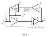
- FIG. 3is a circuit diagram of portions of an example of a drive signal circuit.
- the drive signal circuitprovides a reference drive signal for the MEMS sensor.
- the drive signal circuitincludes an input 335 that receives a voltage signal representative of charge generated by the MEMS sensor.
- the voltage signalis received from a charge-to-voltage converter circuit.
- the drive signal circuitalso includes a phase-shift circuit 340 and a comparator circuit 345 .
- the phase-shift circuit 340can be electrically coupled to the input 335 .
- the phase shift circuit 340shifts the phase of an input signal by substantially ninety degrees) (90°).
- the phase shift circuit 340includes an integrator circuit.
- the comparator circuit 345has hysteresis. The output of the comparator circuit 345 transitions from low to high when the input is greater than a first threshold, and the output transitions from high to low when the input is less than a second threshold that is different from the first threshold.
- the input of the comparator circuit 345can be electrically coupled to the output of the phase-shift circuit 340 , and the output of the comparator circuit 345 can be electrically coupled to the output 350 of the drive signal circuit.
- the drive signal circuitincludes a feedback loop that extends from the output of the drive signal circuit to an input of the phase-shift circuit 340 .
- the feedback loopcan be electrically coupled from the output of the comparator circuit 345 to an input of an amplifier circuit 355 of the integrator circuit.
- the feedback loopcan include a first transconductance amplifier circuit 360 (sometimes called an operational transconductance amplifier or OTA) having an input electrically coupled to the output of the comparator circuit 350 , a second transconductance amplifier circuit 365 having an input electrically coupled to an output of the first transconductance amplifier circuit 360 and an output electrically coupled to an input of the phase-shift circuit 340 .
- the feedback loopcan include a capacitor 370 (C 1 ) coupled to the output of the first transconductance amplifier circuit 360 and circuit ground.
- the configuration of the feedback loopself-generates an oscillating signal or a self-oscillating signal at the output 350 of the drive signal circuit.
- the hysteretic comparator circuitmaintains minimal amplitude of oscillation in the loop (at the integrator output) and controls the range of the self oscillation frequency.
- the binary output of the comparatorcharges/discharge the capacitor 370 through the first transconductance amplifier circuit 360 .
- the error in the self-oscillating signal from a 50% duty cycleis stored onto the capacitor 370 and fed back to the phase-shift circuit 340 though the second transconductance amplifier circuit 365 .
- This feedback arrangementcorrects input signal offsets, amplifier offsets, and comparator offsets to provide a substantially 50% duty cycle output signal.
- Output signals generated by the drive signal circuitare applied to a drive input of the MEMS sensor.
- the output signal provided as the reference drive signalcan be a signal at drive circuit output 350 (OUT) or a signal at the output of the phase-shift circuit 340 (OUT-SINEWAVE).
- the self oscillating signal of the drive signal circuitis selected by the AGC circuit 125 as the reference drive signal for the drive amplifier circuit 120 upon start-up. This self-generated oscillating signal is available at the circuit node labeled OUT in the drive signal circuit.
- the AGC circuit 125may switch the reference drive signal from the signal available at OUT to the signal available at OUT-SINEWAVE as the reference drive signal. This is because after the amplitude threshold is achieved, the OUT-SINEWAVE provides a more harmonically pure (e.g., higher Q) reference drive signal for the MEMS sensor.
- the high-Q signalresults in improved drive and mechanical resonance in the MEMS sensor due to fewer harmonic frequencies.
- the high Q signal at OUT-SINEWAVEprovides an accurate 90 degree phase shift and a substantially 50% duty cycle.
- the feedback arrangementprovides a stable operating point for the forward path integrator.
- the stable operating pointavoids run-away problems that can result from integrating small offsets.
- using an amplifier circuit 355 having a controlled signal gain for direct current (DC) signalsminimizes the frequency shift of the self-oscillating signal over temperature.
- the feedback pathshould be designed to provide a large enough DC current to compensate for input signal offsets, but should have a very low alternating current (AC) gain to not disturb the ninety degree phase shift provided by the forward path integrator.
- ACalternating current
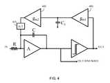
- FIG. 4is a circuit diagram of portions of another example of a drive signal circuit having a feedback loop that includes a first transconductance amplifier circuit 460 and a second transconductance amplifier circuit 465 .
- the drive signal circuitincludes a current divider circuit 475 electrically coupled to the output of the second transconductance amplifier circuit 465 to divide the output current of the second transconductance amplifier circuit 465 .
- FIG. 5is a circuit diagram of portions of another example of a drive signal circuit having a feedback loop that includes a first transconductance amplifier circuit 560 and a second transconductance amplifier circuit 565 .
- the drive signal circuitincludes a resistive divider circuit 575 electrically coupled to the output of the second transconductance amplifier circuit 565 and the input of the phase-shift circuit 540 to divide the output current of the second transconductance amplifier circuit 565 .
- FIG. 6is a circuit diagram of portions of another example of a drive signal circuit having a feedback loop that includes a first transconductance amplifier circuit 660 and a second transconductance amplifier circuit 665 .
- the second transconductance amplifier circuit 665has an input electrically coupled to an output of the first transconductance amplifier circuit and has an output electrically coupled to an input of the integrator amplifier circuit.
- the feedback loopalso includes a resistor 680 coupled to the output of the first transconductance amplifier circuit 660 and a capacitor 670 coupled to the resistor 680 and circuit ground.
- This compensation resistor R 1adds a zero to the feedback transfer function. This adds phase lead to improve the phase margin for high amplitude input signals.
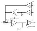
- FIG. 7is a circuit diagram of portions of still another example of a drive signal circuit having a feedback loop that includes a third transconductance amplifier circuit 785 .
- the input of the third transconductance amplifier circuit 785is electrically coupled to the output of a comparator circuit 745 and an input of the integrator amplifier circuit to form a second parallel feedback loop.
- This added transconductance stageeliminates the need for a large compensation resistor and can provide the effective zero to provide phase lead and improve the phase margin high amplitude input signals.
- FIG. 8is a flow diagram of an example of a method 800 of forming a drive signal circuit for a MEMS sensor.
- an input of the drive signal circuitis electrically coupled to an input of an integrator circuit.
- the integrator circuitcan have the circuit topology as shown in the examples herein.
- the output of the integrator circuitis electrically coupled to a comparator circuit having hysteresis.
- a feedback loop in the drive signal circuitis formed to generate a self-oscillating signal at an output of the drive signal circuit when circuit power is applied to the drive signal circuit.
- the feedback loopextends from the output of the comparator circuit to an input of an amplifier (e.g., an operation amplifier or opamp) of the integrator circuit.
- the integrator circuitshifts the phase angle of an input signal received at the input to the drive signal circuit by substantially ninety degrees.
- the received input signalis generated in response to applying the self-oscillating signal to a drive input of the MEMS sensor.
- the drive signal circuitcan be electrically coupled to a capacitance-to-voltage converter circuit, and the input signal can be a voltage signal converted from charge generated by the MEMS sensor in response to applying the self-oscillating signal to the MEMS sensor.
- the drive signal circuitprovides reliable self-startup to provide a drive oscillation signal and also reliably provides a 50% duty cycle.
- the drive signal circuitfurther provides an accurate 90° phase shift that avoids the noise associated with differentiator phase-shifters.
- Example 1can include subject matter (such as an apparatus) comprising a drive signal circuit for a micro-electromechanical system (MEMS) sensor.
- the drive signal circuitincludes an input configured to receive a voltage signal representative of charge generated by the MEMS sensor, a phase-shift circuit electrically coupled to the input and configured to phase shift an input signal by substantially ninety degrees, a comparator circuit with hysteresis, and a feedback loop extending from the output of the drive signal circuit to the input of the phase-shift circuit.
- the comparator circuitcan be electrically coupled to an output of the phase-shift circuit, and an output of the comparator circuit is electrically coupled to an output of the drive signal circuit.
- the feedback loopcan be configured to generate a self-oscillating signal at an output of the drive signal circuit, and the output signal generated by the drive signal circuit is applied to a drive input of the MEMS sensor.
- Example 2can include, or can optionally be combined with the subject matter of Example 1 to optionally include, a first transconductance amplifier circuit having an input electrically coupled to the output of the comparator circuit, a second transconductance amplifier circuit having an input electrically coupled to an output of the first transconductance amplifier circuit and an output electrically coupled to an input of the phase-shift circuit, and a capacitor coupled to the output of the first transconductance amplifier circuit and circuit ground.
- Example 3can include, or can optionally be combined with the subject matter of one or any combination of Examples 1 and 2 to optionally include a current divider circuit electrically coupled to the output of the second transconductance amplifier circuit.
- Example 4can include, or can optionally be combined with the subject matter of one or any combination of Examples 1-3 to optionally include, a resistive divider circuit electrically coupled to the output of the second transconductance amplifier circuit and the input of the phase-shift circuit, wherein the resistive divider is configured to divide the output current of the second transconductance amplifier circuit.
- Example 5can include, or can optionally be combined with the subject matter of one or any combination of Examples 1-4 to optionally include, a phase-shift circuit that includes an integrator circuit that includes an amplifier circuit, and the feedback loop optionally electrically coupled from the output of the comparator circuit to an input of the integrator amplifier circuit.
- Example 6can include, or can optionally be combined with the subject matter of Example 5 to optionally include, an integrator amplifier circuit that provides controlled signal gain for direct current (DC) signals.
- DCdirect current
- Example 7can include, or can optionally be combined with the subject matter of one or any combination of Examples 5 and 6 to include a third transconductance amplifier circuit, and an input of the third transconductance amplifier circuit is electrically coupled to the output of the comparator circuit and an input of the integrator amplifier circuit to form a second feedback loop.
- Example 8can include, or can optionally be combined with the subject matter of one or any combination of Examples 5-7 to optionally include a feedback loop having a first transconductance amplifier circuit having an input electrically coupled to the output of the comparator circuit, a second transconductance amplifier circuit having an input electrically coupled to an output of the first transconductance amplifier circuit and having an output electrically coupled to an input of the integrator amplifier circuit, a resistor coupled to the output of the first transconductance amplifier circuit, and a capacitor coupled to the resistor and circuit ground.
- Example 9can include, or can optionally be combined with the subject matter of one or any combination of Examples 1-8 to optionally include, the MEMS sensor, wherein the MEMS sensor includes a MEMS gyro.
- Example 10can include, or can optionally be combined with the subject matter of one or any combination of Examples 1-9 to include, subject matter (such as a method, a means for performing acts, or a machine readable medium including instructions that, when performed by the machine, can cause the machine to perform acts) comprising self-generating an oscillating signal at an output of a drive signal circuit and applying the oscillating signal to a drive input of the MEMS sensor, receiving, at an input of the drive signal circuit, a voltage signal representative of charge generated by the MEMS sensor in response to applying the oscillation signal to the drive input of the MEMS sensor, shifting the phase of the received voltage signal by substantially ninety degrees and using the phase shifted signal to generate the drive signal, and applying the generated drive signal to the drive input of the MEMS sensor.
- subject mattersuch as a method, a means for performing acts, or a machine readable medium including instructions that, when performed by the machine, can cause the machine to perform acts
- Example 11can include, or can optionally be combined with the subject matter of Example 10 to optionally include integrating the received voltage signal using an integrator circuit.
- Example 12can include or can optionally be combined with the subject matter of Example 11 to optionally include, applying the integrated received voltage signal to a comparator circuit with hysteresis and feeding back the output of the comparator circuit to an input of an amplifier of the integrator circuit to form a feedback loop.
- Example 13can include, or can optionally be combined with the subject matter of Example 12 to optionally include, charging, through a first transconductance amplifier circuit, a capacitor using the output of the comparator circuit, and applying the charge of the capacitor to an input of the amplifier of the integrator circuit through a second transconductance amplifier circuit.
- Example 14can include, or can optionally be combined with the subject matter of one or any combination of Example 13 to optionally include dividing the output current of the second transconductance amplifier circuit to reduce the transconductance of the second transconductance amplifier circuit.
- Example 15can include, or can optionally be combined with the subject matter of one or any combination of Examples 13 and 14 to optionally include electrically coupling an output of the comparator circuit to an input of a third transconductance amplifier circuit and electrically coupling an output of the third transconductance amplifier circuit to an input of the amplifier circuit of the integrator circuit to form a second feedback loop.
- Example 16can include, or can optionally be combined with the subject matter of one or any combination of Examples 13-15 to optionally include includes charging the capacitor through the first transconductance amplifier and a resistor.
- Example 17can include, or can optionally be combined with the subject matter of one or any combination of Examples 11-16 to optionally include, applying the generated drive signal to a drive input of an MEMS gyro sensor.
- Example 18can include, or can optionally be combined with the subject matter of one or any combination of Examples 1-17 to include, subject matter (such as a method, a means for performing acts, or a machine readable medium including instructions that, when performed by the machine, can cause the machine to perform acts) comprising electrically coupling an input of the drive signal circuit to an integrator circuit, electrically coupling an output of the integrator circuit to a comparator circuit having hysteresis, and forming a feedback loop in the drive circuit to generate a self-oscillating signal at an output of the drive signal circuit when circuit power is applied to the drive signal circuit, wherein the feedback loop extends from the output of the comparator circuit to an input of an amplifier of the integrator circuit.
- the integrator circuitshifts the phase angle of an input signal received at the input to the drive signal circuit by substantially ninety degrees, and the input signal is generated in response to applying the self-oscillating signal to a drive input of the MEMS sensor.
- Example 19can include, or can optionally be combined with the subject matter of Example 18 to optionally include, electrically coupling the output of the comparator circuit to a capacitor through a first transconductance amplifier circuit and electrically coupling the capacitor to the phase-shift circuit using a second transconductance amplifier.
- Example 20can include, or can optionally be combined with the subject matter of Example 19 to optionally include, electrically coupling a current divider circuit to the output of the second transconductance amplifier.
- Example 21can include, or can optionally be combined with the subject matter of one or any combination of Examples 18-20 to optionally include, electrically coupling a resistive divider circuit at the input to the integrator circuit.
- Example 22can include, or can optionally be combined with the subject matter of one or any combination of Examples 18-21 to optionally include an amplifier circuit having controlled signal gain for DC signals.
- Example 23can include, or can optionally be combined with the subject matter of one or any combination of Examples 18-22 to optionally include, electrically coupling an output of the comparator circuit to an input of a third transconductance amplifier circuit and electrically coupling an output of the third transconductance amplifier circuit to an input of the amplifier circuit of the integrator circuit to form a second feedback loop.
- Example 24can include, or can optionally be combined with the subject matter of one or any combination of Examples 18-23 to optionally include, generating the input signal in response to applying the self-oscillating signal to a drive input of an MEMS gyro.
- Example 25can include, or can optionally be combined with any portion or combination of portions of any one or more of Examples 1-24 to include, subject matter that can include means for performing any one or more of the functions of Examples 1-24, or a machine readable medium including instructions that, when performed by a machine, cause the machine to perform any one or more of the functions of Examples 1-24.
- the terms “a” or “an”are used, as is common in patent documents, to include one or more than one, independent of any other instances or usages of “at least one” or “one or more.”
- the term “or”is used to refer to a nonexclusive or, such that “A or B” includes “A but not B,” “B but not A,” and “A and B,” unless otherwise indicated.
Landscapes
- Engineering & Computer Science (AREA)
- Signal Processing (AREA)
- Physics & Mathematics (AREA)
- General Physics & Mathematics (AREA)
- Radar, Positioning & Navigation (AREA)
- Remote Sensing (AREA)
- Power Engineering (AREA)
- Gyroscopes (AREA)
- Micromachines (AREA)
Abstract
Description
Claims (24)
Priority Applications (2)
| Application Number | Priority Date | Filing Date | Title |
|---|---|---|---|
| US13/746,016US8754694B2 (en) | 2012-04-03 | 2013-01-21 | Accurate ninety-degree phase shifter |
| EP13001692.6AEP2647953B1 (en) | 2012-04-03 | 2013-04-03 | Accurate ninety degree phase shifter |
Applications Claiming Priority (2)
| Application Number | Priority Date | Filing Date | Title |
|---|---|---|---|
| US201261619604P | 2012-04-03 | 2012-04-03 | |
| US13/746,016US8754694B2 (en) | 2012-04-03 | 2013-01-21 | Accurate ninety-degree phase shifter |
Publications (2)
| Publication Number | Publication Date |
|---|---|
| US20130257487A1 US20130257487A1 (en) | 2013-10-03 |
| US8754694B2true US8754694B2 (en) | 2014-06-17 |
Family
ID=48045245
Family Applications (1)
| Application Number | Title | Priority Date | Filing Date |
|---|---|---|---|
| US13/746,016ActiveUS8754694B2 (en) | 2012-04-03 | 2013-01-21 | Accurate ninety-degree phase shifter |
Country Status (2)
| Country | Link |
|---|---|
| US (1) | US8754694B2 (en) |
| EP (1) | EP2647953B1 (en) |
Cited By (18)
| Publication number | Priority date | Publication date | Assignee | Title |
|---|---|---|---|---|
| US8978475B2 (en) | 2012-02-01 | 2015-03-17 | Fairchild Semiconductor Corporation | MEMS proof mass with split z-axis portions |
| US9006846B2 (en) | 2010-09-20 | 2015-04-14 | Fairchild Semiconductor Corporation | Through silicon via with reduced shunt capacitance |
| US9062972B2 (en) | 2012-01-31 | 2015-06-23 | Fairchild Semiconductor Corporation | MEMS multi-axis accelerometer electrode structure |
| US9069006B2 (en) | 2012-04-05 | 2015-06-30 | Fairchild Semiconductor Corporation | Self test of MEMS gyroscope with ASICs integrated capacitors |
| US9095072B2 (en) | 2010-09-18 | 2015-07-28 | Fairchild Semiconductor Corporation | Multi-die MEMS package |
| US9094027B2 (en) | 2012-04-12 | 2015-07-28 | Fairchild Semiconductor Corporation | Micro-electro-mechanical-system (MEMS) driver |
| US9156673B2 (en) | 2010-09-18 | 2015-10-13 | Fairchild Semiconductor Corporation | Packaging to reduce stress on microelectromechanical systems |
| US9246018B2 (en) | 2010-09-18 | 2016-01-26 | Fairchild Semiconductor Corporation | Micromachined monolithic 3-axis gyroscope with single drive |
| US9278846B2 (en) | 2010-09-18 | 2016-03-08 | Fairchild Semiconductor Corporation | Micromachined monolithic 6-axis inertial sensor |
| US9278845B2 (en) | 2010-09-18 | 2016-03-08 | Fairchild Semiconductor Corporation | MEMS multi-axis gyroscope Z-axis electrode structure |
| US9352961B2 (en) | 2010-09-18 | 2016-05-31 | Fairchild Semiconductor Corporation | Flexure bearing to reduce quadrature for resonating micromachined devices |
| US9425328B2 (en) | 2012-09-12 | 2016-08-23 | Fairchild Semiconductor Corporation | Through silicon via including multi-material fill |
| US9444404B2 (en) | 2012-04-05 | 2016-09-13 | Fairchild Semiconductor Corporation | MEMS device front-end charge amplifier |
| US9488693B2 (en) | 2012-04-04 | 2016-11-08 | Fairchild Semiconductor Corporation | Self test of MEMS accelerometer with ASICS integrated capacitors |
| US9618361B2 (en) | 2012-04-05 | 2017-04-11 | Fairchild Semiconductor Corporation | MEMS device automatic-gain control loop for mechanical amplitude drive |
| US9625272B2 (en) | 2012-04-12 | 2017-04-18 | Fairchild Semiconductor Corporation | MEMS quadrature cancellation and signal demodulation |
| US10060757B2 (en) | 2012-04-05 | 2018-08-28 | Fairchild Semiconductor Corporation | MEMS device quadrature shift cancellation |
| US10065851B2 (en) | 2010-09-20 | 2018-09-04 | Fairchild Semiconductor Corporation | Microelectromechanical pressure sensor including reference capacitor |
Families Citing this family (5)
| Publication number | Priority date | Publication date | Assignee | Title |
|---|---|---|---|---|
| US8710599B2 (en) | 2009-08-04 | 2014-04-29 | Fairchild Semiconductor Corporation | Micromachined devices and fabricating the same |
| US8742964B2 (en) | 2012-04-04 | 2014-06-03 | Fairchild Semiconductor Corporation | Noise reduction method with chopping for a merged MEMS accelerometer sensor |
| FI125611B (en)* | 2014-02-12 | 2015-12-15 | Murata Manufacturing Co | Drive circuit for starting a MEMS resonator |
| JP6219545B1 (en)* | 2017-03-10 | 2017-10-25 | 住友精密工業株式会社 | Vibration type angular velocity sensor |
| US10901021B2 (en)* | 2018-02-27 | 2021-01-26 | Applied Materials, Inc. | Method for detecting wafer processing parameters with micro resonator array sensors |
Citations (126)
| Publication number | Priority date | Publication date | Assignee | Title |
|---|---|---|---|---|
| US5487305A (en) | 1991-12-19 | 1996-01-30 | Motorola, Inc. | Three axes accelerometer |
| US5723790A (en) | 1995-02-27 | 1998-03-03 | Andersson; Gert | Monocrystalline accelerometer and angular rate sensor and methods for making and using same |
| US5751154A (en) | 1996-03-19 | 1998-05-12 | Mitsubishi Denki Kabushiki Kaisha | capacitive sensor interface circuit |
| US5760465A (en) | 1996-02-01 | 1998-06-02 | International Business Machines Corporation | Electronic package with strain relief means |
| US6214644B1 (en) | 2000-06-30 | 2001-04-10 | Amkor Technology, Inc. | Flip-chip micromachine package fabrication method |
| US6301965B1 (en)* | 1999-12-14 | 2001-10-16 | Sandia Corporation | Microelectromechanical accelerometer with resonance-cancelling control circuit including an idle state |
| US20020021059A1 (en) | 2000-07-13 | 2002-02-21 | Bei Technologies, Inc. | Tuning fork and method with reduced quadrature error and symmetrical mass balancing |
| US6351996B1 (en) | 1998-11-12 | 2002-03-05 | Maxim Integrated Products, Inc. | Hermetic packaging for semiconductor pressure sensors |
| US6366468B1 (en) | 2000-04-28 | 2002-04-02 | Hewlett-Packard Company | Self-aligned common carrier |
| US6390905B1 (en) | 2000-03-31 | 2002-05-21 | Speedfam-Ipec Corporation | Workpiece carrier with adjustable pressure zones and barriers |
| US20020178831A1 (en) | 2001-05-29 | 2002-12-05 | Akio Takada | Force sensing device |
| US6501282B1 (en) | 2000-09-29 | 2002-12-31 | Rockwell Automation Technologies, Inc. | Highly sensitive capacitance comparison circuit |
| US6504385B2 (en) | 2001-05-31 | 2003-01-07 | Hewlett-Pakcard Company | Three-axis motion sensor |
| US20030061878A1 (en) | 2001-09-20 | 2003-04-03 | Pinson John C. | Micromechanical inertial sensor having increased pickoff resonance damping |
| US6553835B1 (en) | 2000-09-15 | 2003-04-29 | Bei Technologies, Inc. | Inertial rate sensor and method with improved clocking |
| US20030200807A1 (en) | 2002-04-29 | 2003-10-30 | Hulsing Rand H. | Closed loop analog gyro rate sensor |
| US6725719B2 (en) | 2002-04-17 | 2004-04-27 | Milli Sensor Systems And Actuators, Inc. | MEMS-integrated inertial measurement units on a common substrate |
| US20040119137A1 (en) | 1999-12-21 | 2004-06-24 | Stmicroelectronics S.R.L. | Resistive structure integrated in a semiconductor substrate |
| US6781231B2 (en) | 2002-09-10 | 2004-08-24 | Knowles Electronics Llc | Microelectromechanical system package with environmental and interference shield |
| US20040177689A1 (en) | 2000-07-13 | 2004-09-16 | Dong-Il Cho | Surface/bulk micromachined single-crystalline silicon micro-gyroscope |
| EP1460380A1 (en) | 2003-03-20 | 2004-09-22 | Ngk Insulators, Ltd. | A method and system of exciting a driving vibration in a vibrator |
| US20040211258A1 (en) | 2003-04-28 | 2004-10-28 | Analog Devices, Inc. | Six degree-of-freedom micro-machined multi-sensor |
| US20040219340A1 (en) | 2003-04-29 | 2004-11-04 | Motorola Inc. | Method of adding mass to MEMS structures |
| US20040231420A1 (en) | 2003-02-24 | 2004-11-25 | Huikai Xie | Integrated monolithic tri-axial micromachined accelerometer |
| US20040251793A1 (en) | 2003-05-13 | 2004-12-16 | Kazuhiro Matsuhisa | Micromachine and method of fabricating the same |
| US20050005698A1 (en) | 2003-07-08 | 2005-01-13 | Motorola Inc. | Single proof mass, 3 axis mems transducer |
| JP2005024310A (en) | 2003-06-30 | 2005-01-27 | Kyocera Kinseki Corp | Inertial sensor |
| EP1521086A1 (en) | 2003-10-03 | 2005-04-06 | Matsushita Electric Industrial Co., Ltd. | Inertial sensor and combined sensor therewith |
| US20050139005A1 (en) | 2002-02-06 | 2005-06-30 | Analog Devices, Inc. | Micromachined sensor with quadrature suppression |
| US20050189635A1 (en) | 2004-03-01 | 2005-09-01 | Tessera, Inc. | Packaged acoustic and electromagnetic transducer chips |
| JP2005294462A (en) | 2004-03-31 | 2005-10-20 | Toshiba Corp | Electronic component, electronic component module, and electronic component manufacturing method |
| US20060034472A1 (en) | 2004-08-11 | 2006-02-16 | Seyfollah Bazarjani | Integrated audio codec with silicon audio transducer |
| US20060032308A1 (en) | 2004-08-16 | 2006-02-16 | Cenk Acar | Torsional nonresonant z-axis micromachined gyroscope with non-resonant actuation to measure the angular rotation of an object |
| US20060043608A1 (en) | 2004-08-31 | 2006-03-02 | International Business Machines Corporation | Low stress conductive polymer bump |
| US7051590B1 (en) | 1999-06-15 | 2006-05-30 | Analog Devices Imi, Inc. | Structure for attenuation or cancellation of quadrature error |
| US20060137457A1 (en) | 2003-12-11 | 2006-06-29 | Proteus Biomedical, Inc. | Pressure sensors circuits |
| EP1688705A2 (en) | 2005-02-02 | 2006-08-09 | BEI Sensors & Systems Company, Inc. | Combined gyroscope and 2-axis accelerometer |
| US7093487B2 (en) | 2003-09-29 | 2006-08-22 | Murata Manufacturing Co., Ltd. | Angular-rate detecting apparatus |
| US20060213266A1 (en) | 2005-03-22 | 2006-09-28 | Honeywell International Inc. | Use of electrodes to cancel lift effects in inertial sensors |
| US20060213265A1 (en) | 2005-03-22 | 2006-09-28 | Honeywell International Inc | Quadrature reduction in mems gyro devices using quad steering voltages |
| US20060213268A1 (en) | 2005-03-24 | 2006-09-28 | Denso Corporation | Acceleration sensor and method for manufacturing the same |
| US20060246631A1 (en) | 2005-04-27 | 2006-11-02 | Markus Lutz | Anti-stiction technique for electromechanical systems and electromechanical device employing same |
| US20070013052A1 (en) | 2005-07-15 | 2007-01-18 | Silicon Matrix, Pte., Ltd. | MEMS packaging method for enhanced EMI immunity using flexible substrates |
| US7166910B2 (en) | 2000-11-28 | 2007-01-23 | Knowles Electronics Llc | Miniature silicon condenser microphone |
| JP2007024864A (en) | 2005-06-16 | 2007-02-01 | Mitsubishi Electric Corp | Vibrating gyro |
| US20070040231A1 (en) | 2005-08-16 | 2007-02-22 | Harney Kieran P | Partially etched leadframe packages having different top and bottom topologies |
| US20070047744A1 (en) | 2005-08-23 | 2007-03-01 | Harney Kieran P | Noise mitigating microphone system and method |
| US20070071268A1 (en) | 2005-08-16 | 2007-03-29 | Analog Devices, Inc. | Packaged microphone with electrically coupled lid |
| US7210351B2 (en) | 2004-06-10 | 2007-05-01 | Chung Shan Institute Of Science And Technology | Micro accelerometer |
| US20070099327A1 (en) | 2002-04-23 | 2007-05-03 | Sharp Laboratories Of America, Inc. | Method for integrated MEMS packaging |
| US7221767B2 (en) | 1999-09-07 | 2007-05-22 | Sonion Mems A/S | Surface mountable transducer system |
| US20070114643A1 (en) | 2005-11-22 | 2007-05-24 | Honeywell International Inc. | Mems flip-chip packaging |
| US7240552B2 (en) | 2005-06-06 | 2007-07-10 | Bei Technologies, Inc. | Torsional rate sensor with momentum balance and mode decoupling |
| US20070165888A1 (en) | 2005-04-25 | 2007-07-19 | Analog Devices, Inc. | Support Apparatus for Microphone Diaphragm |
| US7258011B2 (en) | 2005-11-21 | 2007-08-21 | Invensense Inc. | Multiple axis accelerometer |
| US20070205492A1 (en) | 2006-03-03 | 2007-09-06 | Silicon Matrix, Pte. Ltd. | MEMS microphone with a stacked PCB package and method of producing the same |
| US20070222021A1 (en) | 2006-03-10 | 2007-09-27 | Rockwell Scientific Licensing, Llc | Shielded through-via |
| US20070220973A1 (en) | 2005-08-12 | 2007-09-27 | Cenk Acar | Multi-axis micromachined accelerometer and rate sensor |
| US7293460B2 (en) | 2005-03-16 | 2007-11-13 | Delphi Technologies, Inc. | Multiple-axis linear accelerometer |
| US7301212B1 (en) | 2004-07-30 | 2007-11-27 | National Semiconductor Corporation | MEMS microphone |
| EP1860402A1 (en) | 2006-05-24 | 2007-11-28 | Hitachi Metals, Ltd. | Angular rate sensor |
| US7305880B2 (en) | 2004-08-03 | 2007-12-11 | Stmicroelectronics S.R.L. | Resonant micro-electro-mechanical system with analog driving |
| US20070284682A1 (en) | 2006-03-20 | 2007-12-13 | Laming Richard I | Mems process and device |
| US20080049230A1 (en) | 2006-05-19 | 2008-02-28 | Chin Ken K | Mems fiber optic microphone |
| US20080081398A1 (en) | 2006-10-02 | 2008-04-03 | Fionix Inc. | Cap Wafer for Wafer Bonded Packaging and Method for Manufacturing the Same |
| US20080083958A1 (en) | 2006-10-05 | 2008-04-10 | Wen-Chieh Wei | Micro-electromechanical system package |
| US20080083960A1 (en) | 2006-08-29 | 2008-04-10 | Industrial Technology Research Institute | Package structure and packaging method of mems microphone |
| US7358151B2 (en) | 2004-12-21 | 2008-04-15 | Sony Corporation | Microelectromechanical system microphone fabrication including signal processing circuitry on common substrate |
| US20080092652A1 (en) | 2006-10-23 | 2008-04-24 | Cenk Acar | Dual Axis Rate Sensor |
| WO2008059757A1 (en) | 2006-11-14 | 2008-05-22 | Panasonic Corporation | Sensor |
| US20080157238A1 (en) | 2006-12-29 | 2008-07-03 | Wei-Min Hsiao | Mems microphone module and method thereof |
| US20080157301A1 (en) | 2007-01-03 | 2008-07-03 | Stats Chippac, Inc. | Leadframe package for mems microphone assembly |
| WO2008087578A2 (en) | 2007-01-17 | 2008-07-24 | Nxp B.V. | A system-in-package with through substrate via holes |
| US20080202237A1 (en) | 2007-02-28 | 2008-08-28 | Dirk Hammerschmidt | Sensor And Method For Sensing The Linear Acceleration And An Angular Velocity |
| US20080245148A1 (en) | 2007-04-03 | 2008-10-09 | Sony Corporation | Inertial sensor and electrical or electronic device |
| US20080247585A1 (en) | 2005-02-24 | 2008-10-09 | Epcos Ag | Electrical Module Comprising a Mems Microphone |
| US20080251866A1 (en) | 2007-04-10 | 2008-10-16 | Honeywell International Inc. | Low-stress hermetic die attach |
| US7451647B2 (en)* | 2005-10-21 | 2008-11-18 | Sony Corporation | MEMS sensor driving device, MEMS sensor driving method, and active sensor using MEMS |
| US20080290756A1 (en) | 2005-06-17 | 2008-11-27 | Kolo Technologies, Inc. | Micro-Electro-Mechanical Transducer Having an Insulation Extension |
| US20080302559A1 (en) | 1992-04-08 | 2008-12-11 | Elm Technology Corporation | Flexible and elastic dielectric integrated circuit |
| US20080314147A1 (en) | 2007-06-21 | 2008-12-25 | Invensense Inc. | Vertically integrated 3-axis mems accelerometer with electronics |
| US20090064780A1 (en) | 2007-09-11 | 2009-03-12 | Stmicroelectronics S.R.L. | Microelectromechanical sensor with improved mechanical decoupling of sensing and driving modes |
| JP2009075097A (en) | 2007-08-30 | 2009-04-09 | Denso Corp | Capacitive physical quantity detector |
| US7518493B2 (en) | 2005-12-01 | 2009-04-14 | Lv Sensors, Inc. | Integrated tire pressure sensor system |
| US7539003B2 (en) | 2005-12-01 | 2009-05-26 | Lv Sensors, Inc. | Capacitive micro-electro-mechanical sensors with single crystal silicon electrodes |
| US20090140606A1 (en) | 2005-05-18 | 2009-06-04 | Kolo Technologies, Inc. | Micro-Electro-Mechanical Transducers |
| US20090175477A1 (en) | 2007-08-20 | 2009-07-09 | Yamaha Corporation | Vibration transducer |
| US20090183570A1 (en) | 2008-01-18 | 2009-07-23 | Custom Sensors & Technologies, Inc. | Micromachined cross-differential dual-axis accelerometer |
| US20090194829A1 (en) | 2008-01-31 | 2009-08-06 | Shine Chung | MEMS Packaging Including Integrated Circuit Dies |
| US7600428B2 (en) | 2006-03-14 | 2009-10-13 | Commissariat A L'energie Atomique | Triaxial membrane accelerometer |
| US7622782B2 (en) | 2005-08-24 | 2009-11-24 | General Electric Company | Pressure sensors and methods of making the same |
| US20100019393A1 (en) | 2008-07-23 | 2010-01-28 | Industrial Technology Research Institute | Packaging structure for integration of microelectronics and mems devices by 3d stacking and method for manufacturing the same |
| US20100024548A1 (en) | 2006-04-24 | 2010-02-04 | Donato Cardarelli | Scale Factor Measurement For Mems Gyroscopes And Accelerometers |
| JP2010025898A (en) | 2008-07-24 | 2010-02-04 | Yamaha Corp | Mems sensor |
| US20100038733A1 (en) | 2008-08-14 | 2010-02-18 | Knowles Electronics, Llc | Microelectromichanical system package with strain relief bridge |
| JP2010506182A (en) | 2006-10-12 | 2010-02-25 | フラウンホーファー・ゲゼルシャフト ツーァ フェルデルンク デァ アンゲヴァンテン フォルシュンク エー ファウ | Acceleration detection sensor |
| US20100052082A1 (en) | 2008-09-03 | 2010-03-04 | Solid State System Co., Ltd. | Micro-electro-mechanical systems (mems) package and method for forming the mems package |
| US20100072626A1 (en) | 2008-09-19 | 2010-03-25 | Infineon Technologies Ag | Wafer level packaged mems integrated circuit |
| US7706149B2 (en) | 2007-08-17 | 2010-04-27 | Advanced Semiconductor Engineering, Inc. | Micro-electro-mechanical-system package and method for manufacturing the same |
| US20100155863A1 (en) | 2005-08-11 | 2010-06-24 | Koninklijke Philips Electronics, N.V. | Method for manufacturing a microelectronic package comprising a silicon mems microphone |
| US20100206074A1 (en) | 2009-02-19 | 2010-08-19 | Seiko Epson Corporation | Oscillation drive device, physical quantity measurement device and electronic apparatus |
| US20100224004A1 (en) | 2009-03-03 | 2010-09-09 | S3C, Inc. | Media-compatible electrically isolated pressure sensor for high temperature applications |
| US20100236327A1 (en) | 2009-03-17 | 2010-09-23 | Minyao Mao | Tri-axis Angular Rate Sensor |
| EP2259019A1 (en) | 2009-06-03 | 2010-12-08 | STMicroelectronics S.r.l. | Microelectromechanical gyroscope with position control driving and method for controlling a microelectromechanical gyroscope |
| US20110031565A1 (en) | 2009-08-04 | 2011-02-10 | David Lambe Marx | Micromachined devices and fabricating the same |
| WO2011016859A2 (en) | 2009-08-04 | 2011-02-10 | Cenk Acar | Micromachined inertial sensor devices |
| US20110030474A1 (en) | 2009-08-04 | 2011-02-10 | Analog Devices, Inc. | Inertial Sensors with Reduced Sensitivity to Quadrature Errors and Micromachining Inaccuracies |
| US20110094302A1 (en) | 2009-10-23 | 2011-04-28 | The Regents Of The University Of California | Micromachined Gyroscopes with 2-DOF Sense Modes Allowing Interchangeable Robust and Precision Operation |
| US20110121413A1 (en) | 2009-11-17 | 2011-05-26 | Howard Allen | Microelectromechanical systems microphone packaging systems |
| US8006557B2 (en) | 2007-05-16 | 2011-08-30 | Intellisense Software Corporation | Multi-axis sensor |
| US20110265564A1 (en) | 2010-04-30 | 2011-11-03 | Qualcomm Mems Technologies, Inc. | Micromachined piezoelectric x-axis gyroscope |
| US8113050B2 (en) | 2006-01-25 | 2012-02-14 | The Regents Of The University Of California | Robust six degree-of-freedom micromachined gyroscope with anti-phase drive scheme and method of operation of the same |
| WO2012037536A2 (en) | 2010-09-18 | 2012-03-22 | Fairchild Semiconductor Corporation | Packaging to reduce stress on microelectromechanical systems |
| WO2012037540A2 (en) | 2010-09-18 | 2012-03-22 | Fairchild Semiconductor Corporation | Micromachined monolithic 3-axis gyroscope with single drive |
| WO2012037501A2 (en) | 2010-09-18 | 2012-03-22 | Cenk Acar | Flexure bearing to reduce quadrature for resonating micromachined devices |
| WO2012037538A2 (en) | 2010-09-18 | 2012-03-22 | Fairchild Semiconductor Corporation | Micromachined monolithic 6-axis inertial sensor |
| WO2012037492A2 (en) | 2010-09-18 | 2012-03-22 | Janusz Bryzek | Multi-die mems package |
| WO2012040245A2 (en) | 2010-09-20 | 2012-03-29 | Fairchild Semiconductor Corporation | Through silicon via with reduced shunt capacitance |
| WO2012040194A1 (en) | 2010-09-20 | 2012-03-29 | Fairchild Semiconductor Corporation | Inertial sensor mode tuning circuit |
| WO2012040211A2 (en) | 2010-09-20 | 2012-03-29 | Fairchild Semiconductor Corporation | Microelectromechanical pressure sensor including reference capacitor |
| US8171792B2 (en) | 2007-11-21 | 2012-05-08 | Sony Corporation | Inertia sensor and inertia detector device |
| US8250921B2 (en) | 2007-07-06 | 2012-08-28 | Invensense, Inc. | Integrated motion processing unit (MPU) with MEMS inertial sensing and embedded digital electronics |
| US20130139592A1 (en) | 2010-09-18 | 2013-06-06 | Fairchild Semiconductor Corporation | Mems multi-axis gyroscope z-axis electrode structure |
| US20130192369A1 (en) | 2012-01-31 | 2013-08-01 | Cenk Acar | Mems multi-axis accelerometer electrode structure |
| US20130192364A1 (en) | 2012-02-01 | 2013-08-01 | Cenk Acar | Mems proof mass with split z-axis portions |
| WO2013116514A1 (en) | 2012-02-01 | 2013-08-08 | Cenk Acar | Mems multi-axis gyroscope with central suspension and gimbal structure |
- 2013
- 2013-01-21USUS13/746,016patent/US8754694B2/enactiveActive
- 2013-04-03EPEP13001692.6Apatent/EP2647953B1/enactiveActive
Patent Citations (165)
| Publication number | Priority date | Publication date | Assignee | Title |
|---|---|---|---|---|
| US5487305A (en) | 1991-12-19 | 1996-01-30 | Motorola, Inc. | Three axes accelerometer |
| US20080302559A1 (en) | 1992-04-08 | 2008-12-11 | Elm Technology Corporation | Flexible and elastic dielectric integrated circuit |
| US5723790A (en) | 1995-02-27 | 1998-03-03 | Andersson; Gert | Monocrystalline accelerometer and angular rate sensor and methods for making and using same |
| US5760465A (en) | 1996-02-01 | 1998-06-02 | International Business Machines Corporation | Electronic package with strain relief means |
| US5751154A (en) | 1996-03-19 | 1998-05-12 | Mitsubishi Denki Kabushiki Kaisha | capacitive sensor interface circuit |
| US6351996B1 (en) | 1998-11-12 | 2002-03-05 | Maxim Integrated Products, Inc. | Hermetic packaging for semiconductor pressure sensors |
| US7051590B1 (en) | 1999-06-15 | 2006-05-30 | Analog Devices Imi, Inc. | Structure for attenuation or cancellation of quadrature error |
| US7221767B2 (en) | 1999-09-07 | 2007-05-22 | Sonion Mems A/S | Surface mountable transducer system |
| US6301965B1 (en)* | 1999-12-14 | 2001-10-16 | Sandia Corporation | Microelectromechanical accelerometer with resonance-cancelling control circuit including an idle state |
| US20040119137A1 (en) | 1999-12-21 | 2004-06-24 | Stmicroelectronics S.R.L. | Resistive structure integrated in a semiconductor substrate |
| US6390905B1 (en) | 2000-03-31 | 2002-05-21 | Speedfam-Ipec Corporation | Workpiece carrier with adjustable pressure zones and barriers |
| US6366468B1 (en) | 2000-04-28 | 2002-04-02 | Hewlett-Packard Company | Self-aligned common carrier |
| US6214644B1 (en) | 2000-06-30 | 2001-04-10 | Amkor Technology, Inc. | Flip-chip micromachine package fabrication method |
| US20020021059A1 (en) | 2000-07-13 | 2002-02-21 | Bei Technologies, Inc. | Tuning fork and method with reduced quadrature error and symmetrical mass balancing |
| US20040177689A1 (en) | 2000-07-13 | 2004-09-16 | Dong-Il Cho | Surface/bulk micromachined single-crystalline silicon micro-gyroscope |
| US6553835B1 (en) | 2000-09-15 | 2003-04-29 | Bei Technologies, Inc. | Inertial rate sensor and method with improved clocking |
| US6501282B1 (en) | 2000-09-29 | 2002-12-31 | Rockwell Automation Technologies, Inc. | Highly sensitive capacitance comparison circuit |
| US7166910B2 (en) | 2000-11-28 | 2007-01-23 | Knowles Electronics Llc | Miniature silicon condenser microphone |
| US20020178831A1 (en) | 2001-05-29 | 2002-12-05 | Akio Takada | Force sensing device |
| US6504385B2 (en) | 2001-05-31 | 2003-01-07 | Hewlett-Pakcard Company | Three-axis motion sensor |
| US20030061878A1 (en) | 2001-09-20 | 2003-04-03 | Pinson John C. | Micromechanical inertial sensor having increased pickoff resonance damping |
| US20050139005A1 (en) | 2002-02-06 | 2005-06-30 | Analog Devices, Inc. | Micromachined sensor with quadrature suppression |
| US6725719B2 (en) | 2002-04-17 | 2004-04-27 | Milli Sensor Systems And Actuators, Inc. | MEMS-integrated inertial measurement units on a common substrate |
| US20070099327A1 (en) | 2002-04-23 | 2007-05-03 | Sharp Laboratories Of America, Inc. | Method for integrated MEMS packaging |
| US20030200807A1 (en) | 2002-04-29 | 2003-10-30 | Hulsing Rand H. | Closed loop analog gyro rate sensor |
| US6781231B2 (en) | 2002-09-10 | 2004-08-24 | Knowles Electronics Llc | Microelectromechanical system package with environmental and interference shield |
| US20040231420A1 (en) | 2003-02-24 | 2004-11-25 | Huikai Xie | Integrated monolithic tri-axial micromachined accelerometer |
| US7258012B2 (en) | 2003-02-24 | 2007-08-21 | University Of Florida Research Foundation, Inc. | Integrated monolithic tri-axial micromachined accelerometer |
| EP1460380A1 (en) | 2003-03-20 | 2004-09-22 | Ngk Insulators, Ltd. | A method and system of exciting a driving vibration in a vibrator |
| US20040211258A1 (en) | 2003-04-28 | 2004-10-28 | Analog Devices, Inc. | Six degree-of-freedom micro-machined multi-sensor |
| US6848304B2 (en) | 2003-04-28 | 2005-02-01 | Analog Devices, Inc. | Six degree-of-freedom micro-machined multi-sensor |
| US20040219340A1 (en) | 2003-04-29 | 2004-11-04 | Motorola Inc. | Method of adding mass to MEMS structures |
| US20040251793A1 (en) | 2003-05-13 | 2004-12-16 | Kazuhiro Matsuhisa | Micromachine and method of fabricating the same |
| JP2005024310A (en) | 2003-06-30 | 2005-01-27 | Kyocera Kinseki Corp | Inertial sensor |
| US20050005698A1 (en) | 2003-07-08 | 2005-01-13 | Motorola Inc. | Single proof mass, 3 axis mems transducer |
| US7093487B2 (en) | 2003-09-29 | 2006-08-22 | Murata Manufacturing Co., Ltd. | Angular-rate detecting apparatus |
| JP2005114394A (en) | 2003-10-03 | 2005-04-28 | Matsushita Electric Ind Co Ltd | Inertial sensor and composite sensor using the same |
| EP1521086A1 (en) | 2003-10-03 | 2005-04-06 | Matsushita Electric Industrial Co., Ltd. | Inertial sensor and combined sensor therewith |
| US20060137457A1 (en) | 2003-12-11 | 2006-06-29 | Proteus Biomedical, Inc. | Pressure sensors circuits |
| US20050189635A1 (en) | 2004-03-01 | 2005-09-01 | Tessera, Inc. | Packaged acoustic and electromagnetic transducer chips |
| JP2005294462A (en) | 2004-03-31 | 2005-10-20 | Toshiba Corp | Electronic component, electronic component module, and electronic component manufacturing method |
| US7210351B2 (en) | 2004-06-10 | 2007-05-01 | Chung Shan Institute Of Science And Technology | Micro accelerometer |
| US7301212B1 (en) | 2004-07-30 | 2007-11-27 | National Semiconductor Corporation | MEMS microphone |
| US7305880B2 (en) | 2004-08-03 | 2007-12-11 | Stmicroelectronics S.R.L. | Resonant micro-electro-mechanical system with analog driving |
| US20060034472A1 (en) | 2004-08-11 | 2006-02-16 | Seyfollah Bazarjani | Integrated audio codec with silicon audio transducer |
| US20060032308A1 (en) | 2004-08-16 | 2006-02-16 | Cenk Acar | Torsional nonresonant z-axis micromachined gyroscope with non-resonant actuation to measure the angular rotation of an object |
| US20060043608A1 (en) | 2004-08-31 | 2006-03-02 | International Business Machines Corporation | Low stress conductive polymer bump |
| US7358151B2 (en) | 2004-12-21 | 2008-04-15 | Sony Corporation | Microelectromechanical system microphone fabrication including signal processing circuitry on common substrate |
| EP1688705A2 (en) | 2005-02-02 | 2006-08-09 | BEI Sensors & Systems Company, Inc. | Combined gyroscope and 2-axis accelerometer |
| US20080247585A1 (en) | 2005-02-24 | 2008-10-09 | Epcos Ag | Electrical Module Comprising a Mems Microphone |
| US7293460B2 (en) | 2005-03-16 | 2007-11-13 | Delphi Technologies, Inc. | Multiple-axis linear accelerometer |
| US20060213265A1 (en) | 2005-03-22 | 2006-09-28 | Honeywell International Inc | Quadrature reduction in mems gyro devices using quad steering voltages |
| US20060213266A1 (en) | 2005-03-22 | 2006-09-28 | Honeywell International Inc. | Use of electrodes to cancel lift effects in inertial sensors |
| US20060213268A1 (en) | 2005-03-24 | 2006-09-28 | Denso Corporation | Acceleration sensor and method for manufacturing the same |
| US20070165888A1 (en) | 2005-04-25 | 2007-07-19 | Analog Devices, Inc. | Support Apparatus for Microphone Diaphragm |
| US7449355B2 (en) | 2005-04-27 | 2008-11-11 | Robert Bosch Gmbh | Anti-stiction technique for electromechanical systems and electromechanical device employing same |
| US20060246631A1 (en) | 2005-04-27 | 2006-11-02 | Markus Lutz | Anti-stiction technique for electromechanical systems and electromechanical device employing same |
| US20090140606A1 (en) | 2005-05-18 | 2009-06-04 | Kolo Technologies, Inc. | Micro-Electro-Mechanical Transducers |
| US7240552B2 (en) | 2005-06-06 | 2007-07-10 | Bei Technologies, Inc. | Torsional rate sensor with momentum balance and mode decoupling |
| JP2007024864A (en) | 2005-06-16 | 2007-02-01 | Mitsubishi Electric Corp | Vibrating gyro |
| US20080290756A1 (en) | 2005-06-17 | 2008-11-27 | Kolo Technologies, Inc. | Micro-Electro-Mechanical Transducer Having an Insulation Extension |
| US20070013052A1 (en) | 2005-07-15 | 2007-01-18 | Silicon Matrix, Pte., Ltd. | MEMS packaging method for enhanced EMI immunity using flexible substrates |
| US7202552B2 (en) | 2005-07-15 | 2007-04-10 | Silicon Matrix Pte. Ltd. | MEMS package using flexible substrates, and method thereof |
| US20100155863A1 (en) | 2005-08-11 | 2010-06-24 | Koninklijke Philips Electronics, N.V. | Method for manufacturing a microelectronic package comprising a silicon mems microphone |
| US20070220973A1 (en) | 2005-08-12 | 2007-09-27 | Cenk Acar | Multi-axis micromachined accelerometer and rate sensor |
| US20070071268A1 (en) | 2005-08-16 | 2007-03-29 | Analog Devices, Inc. | Packaged microphone with electrically coupled lid |
| US20070040231A1 (en) | 2005-08-16 | 2007-02-22 | Harney Kieran P | Partially etched leadframe packages having different top and bottom topologies |
| US20070047744A1 (en) | 2005-08-23 | 2007-03-01 | Harney Kieran P | Noise mitigating microphone system and method |
| US7622782B2 (en) | 2005-08-24 | 2009-11-24 | General Electric Company | Pressure sensors and methods of making the same |
| US7451647B2 (en)* | 2005-10-21 | 2008-11-18 | Sony Corporation | MEMS sensor driving device, MEMS sensor driving method, and active sensor using MEMS |
| US7258011B2 (en) | 2005-11-21 | 2007-08-21 | Invensense Inc. | Multiple axis accelerometer |
| US20070114643A1 (en) | 2005-11-22 | 2007-05-24 | Honeywell International Inc. | Mems flip-chip packaging |
| US7518493B2 (en) | 2005-12-01 | 2009-04-14 | Lv Sensors, Inc. | Integrated tire pressure sensor system |
| US7539003B2 (en) | 2005-12-01 | 2009-05-26 | Lv Sensors, Inc. | Capacitive micro-electro-mechanical sensors with single crystal silicon electrodes |
| US8113050B2 (en) | 2006-01-25 | 2012-02-14 | The Regents Of The University Of California | Robust six degree-of-freedom micromachined gyroscope with anti-phase drive scheme and method of operation of the same |
| US7436054B2 (en) | 2006-03-03 | 2008-10-14 | Silicon Matrix, Pte. Ltd. | MEMS microphone with a stacked PCB package and method of producing the same |
| US20070205492A1 (en) | 2006-03-03 | 2007-09-06 | Silicon Matrix, Pte. Ltd. | MEMS microphone with a stacked PCB package and method of producing the same |
| US20070222021A1 (en) | 2006-03-10 | 2007-09-27 | Rockwell Scientific Licensing, Llc | Shielded through-via |
| US7600428B2 (en) | 2006-03-14 | 2009-10-13 | Commissariat A L'energie Atomique | Triaxial membrane accelerometer |
| US20070284682A1 (en) | 2006-03-20 | 2007-12-13 | Laming Richard I | Mems process and device |
| US7781249B2 (en) | 2006-03-20 | 2010-08-24 | Wolfson Microelectronics Plc | MEMS process and device |
| US20100024548A1 (en) | 2006-04-24 | 2010-02-04 | Donato Cardarelli | Scale Factor Measurement For Mems Gyroscopes And Accelerometers |
| US20080049230A1 (en) | 2006-05-19 | 2008-02-28 | Chin Ken K | Mems fiber optic microphone |
| EP1860402A1 (en) | 2006-05-24 | 2007-11-28 | Hitachi Metals, Ltd. | Angular rate sensor |
| US20080083960A1 (en) | 2006-08-29 | 2008-04-10 | Industrial Technology Research Institute | Package structure and packaging method of mems microphone |
| US20080081398A1 (en) | 2006-10-02 | 2008-04-03 | Fionix Inc. | Cap Wafer for Wafer Bonded Packaging and Method for Manufacturing the Same |
| US20080083958A1 (en) | 2006-10-05 | 2008-04-10 | Wen-Chieh Wei | Micro-electromechanical system package |
| JP2010506182A (en) | 2006-10-12 | 2010-02-25 | フラウンホーファー・ゲゼルシャフト ツーァ フェルデルンク デァ アンゲヴァンテン フォルシュンク エー ファウ | Acceleration detection sensor |
| US20080092652A1 (en) | 2006-10-23 | 2008-04-24 | Cenk Acar | Dual Axis Rate Sensor |
| US20090266163A1 (en) | 2006-11-14 | 2009-10-29 | Panasonic Corporation | Sensor |
| US8201449B2 (en) | 2006-11-14 | 2012-06-19 | Panasonic Corporation | Sensor |
| WO2008059757A1 (en) | 2006-11-14 | 2008-05-22 | Panasonic Corporation | Sensor |
| US20080157238A1 (en) | 2006-12-29 | 2008-07-03 | Wei-Min Hsiao | Mems microphone module and method thereof |
| US20080157301A1 (en) | 2007-01-03 | 2008-07-03 | Stats Chippac, Inc. | Leadframe package for mems microphone assembly |
| US20090263937A1 (en) | 2007-01-03 | 2009-10-22 | Stats Chippac, Inc. | Leadframe package for mems microphone assembly |
| US7795078B2 (en) | 2007-01-03 | 2010-09-14 | Stats Chippac, Ltd. | Leadframe package for MEMS microphone assembly |
| WO2008087578A2 (en) | 2007-01-17 | 2008-07-24 | Nxp B.V. | A system-in-package with through substrate via holes |
| US20100044853A1 (en) | 2007-01-17 | 2010-02-25 | Nxp, B.V. | System-in-package with through substrate via holes |
| US7950281B2 (en) | 2007-02-28 | 2011-05-31 | Infineon Technologies Ag | Sensor and method for sensing linear acceleration and angular velocity |
| US20080202237A1 (en) | 2007-02-28 | 2008-08-28 | Dirk Hammerschmidt | Sensor And Method For Sensing The Linear Acceleration And An Angular Velocity |
| US20080245148A1 (en) | 2007-04-03 | 2008-10-09 | Sony Corporation | Inertial sensor and electrical or electronic device |
| US20080251866A1 (en) | 2007-04-10 | 2008-10-16 | Honeywell International Inc. | Low-stress hermetic die attach |
| US8006557B2 (en) | 2007-05-16 | 2011-08-30 | Intellisense Software Corporation | Multi-axis sensor |
| US20080314147A1 (en) | 2007-06-21 | 2008-12-25 | Invensense Inc. | Vertically integrated 3-axis mems accelerometer with electronics |
| US8250921B2 (en) | 2007-07-06 | 2012-08-28 | Invensense, Inc. | Integrated motion processing unit (MPU) with MEMS inertial sensing and embedded digital electronics |
| US7706149B2 (en) | 2007-08-17 | 2010-04-27 | Advanced Semiconductor Engineering, Inc. | Micro-electro-mechanical-system package and method for manufacturing the same |
| US20090175477A1 (en) | 2007-08-20 | 2009-07-09 | Yamaha Corporation | Vibration transducer |
| JP2009075097A (en) | 2007-08-30 | 2009-04-09 | Denso Corp | Capacitive physical quantity detector |
| US20090064780A1 (en) | 2007-09-11 | 2009-03-12 | Stmicroelectronics S.R.L. | Microelectromechanical sensor with improved mechanical decoupling of sensing and driving modes |
| US8171792B2 (en) | 2007-11-21 | 2012-05-08 | Sony Corporation | Inertia sensor and inertia detector device |
| US20090183570A1 (en) | 2008-01-18 | 2009-07-23 | Custom Sensors & Technologies, Inc. | Micromachined cross-differential dual-axis accelerometer |
| US20090194829A1 (en) | 2008-01-31 | 2009-08-06 | Shine Chung | MEMS Packaging Including Integrated Circuit Dies |
| US20100019393A1 (en) | 2008-07-23 | 2010-01-28 | Industrial Technology Research Institute | Packaging structure for integration of microelectronics and mems devices by 3d stacking and method for manufacturing the same |
| JP2010025898A (en) | 2008-07-24 | 2010-02-04 | Yamaha Corp | Mems sensor |
| US20100038733A1 (en) | 2008-08-14 | 2010-02-18 | Knowles Electronics, Llc | Microelectromichanical system package with strain relief bridge |
| US20100052082A1 (en) | 2008-09-03 | 2010-03-04 | Solid State System Co., Ltd. | Micro-electro-mechanical systems (mems) package and method for forming the mems package |
| US20100072626A1 (en) | 2008-09-19 | 2010-03-25 | Infineon Technologies Ag | Wafer level packaged mems integrated circuit |
| US20100206074A1 (en) | 2009-02-19 | 2010-08-19 | Seiko Epson Corporation | Oscillation drive device, physical quantity measurement device and electronic apparatus |
| US20100224004A1 (en) | 2009-03-03 | 2010-09-09 | S3C, Inc. | Media-compatible electrically isolated pressure sensor for high temperature applications |
| US20100236327A1 (en) | 2009-03-17 | 2010-09-23 | Minyao Mao | Tri-axis Angular Rate Sensor |
| EP2259019A1 (en) | 2009-06-03 | 2010-12-08 | STMicroelectronics S.r.l. | Microelectromechanical gyroscope with position control driving and method for controlling a microelectromechanical gyroscope |
| US20110030473A1 (en) | 2009-08-04 | 2011-02-10 | Cenk Acar | Micromachined inertial sensor devices |
| WO2011016859A3 (en) | 2009-08-04 | 2011-04-21 | Cenk Acar | Micromachined inertial sensor devices |
| US20110031565A1 (en) | 2009-08-04 | 2011-02-10 | David Lambe Marx | Micromachined devices and fabricating the same |
| CN102597699A (en) | 2009-08-04 | 2012-07-18 | 飞兆半导体公司 | Micromachined inertial sensor devices |
| WO2011016859A2 (en) | 2009-08-04 | 2011-02-10 | Cenk Acar | Micromachined inertial sensor devices |
| US20110030474A1 (en) | 2009-08-04 | 2011-02-10 | Analog Devices, Inc. | Inertial Sensors with Reduced Sensitivity to Quadrature Errors and Micromachining Inaccuracies |
| US20110094302A1 (en) | 2009-10-23 | 2011-04-28 | The Regents Of The University Of California | Micromachined Gyroscopes with 2-DOF Sense Modes Allowing Interchangeable Robust and Precision Operation |
| US20110121413A1 (en) | 2009-11-17 | 2011-05-26 | Howard Allen | Microelectromechanical systems microphone packaging systems |
| US8421168B2 (en) | 2009-11-17 | 2013-04-16 | Fairchild Semiconductor Corporation | Microelectromechanical systems microphone packaging systems |
| US20110265564A1 (en) | 2010-04-30 | 2011-11-03 | Qualcomm Mems Technologies, Inc. | Micromachined piezoelectric x-axis gyroscope |
| WO2012037492A2 (en) | 2010-09-18 | 2012-03-22 | Janusz Bryzek | Multi-die mems package |
| CN103221779A (en) | 2010-09-18 | 2013-07-24 | 快捷半导体公司 | Micromachined monolithic 6-xis inertial sensor |
| US20130247666A1 (en) | 2010-09-18 | 2013-09-26 | Fairchild Semiconductor Corporation | Micromachined 3-axis accelerometer with a single proof-mass |
| US20130250532A1 (en) | 2010-09-18 | 2013-09-26 | Fairchild Semiconductor Corporation | Multi-die mems package |
| CN103238075A (en) | 2010-09-18 | 2013-08-07 | 快捷半导体公司 | Micromachined 3-axis accelerometer with a single proof-mass |
| WO2012037539A9 (en) | 2010-09-18 | 2012-04-26 | Fairchild Semiconductor Corporation | Micromachined 3-axis accelerometer with a single proof-mass |
| WO2012037537A2 (en) | 2010-09-18 | 2012-03-22 | Fairchild Semiconductor Corporation | Sealed packaging for microelectromechanical systems |
| WO2012037501A3 (en) | 2010-09-18 | 2012-06-07 | Cenk Acar | Flexure bearing to reduce quadrature for resonating micromachined devices |
| WO2012037492A3 (en) | 2010-09-18 | 2012-06-07 | Janusz Bryzek | Multi-die mems package |
| CN103221331A (en) | 2010-09-18 | 2013-07-24 | 快捷半导体公司 | Sealed packaging for microelectromechanical systems |
| WO2012037538A2 (en) | 2010-09-18 | 2012-03-22 | Fairchild Semiconductor Corporation | Micromachined monolithic 6-axis inertial sensor |
| WO2012037501A2 (en) | 2010-09-18 | 2012-03-22 | Cenk Acar | Flexure bearing to reduce quadrature for resonating micromachined devices |
| WO2012037540A2 (en) | 2010-09-18 | 2012-03-22 | Fairchild Semiconductor Corporation | Micromachined monolithic 3-axis gyroscope with single drive |
| WO2012037536A2 (en) | 2010-09-18 | 2012-03-22 | Fairchild Semiconductor Corporation | Packaging to reduce stress on microelectromechanical systems |
| US20130139592A1 (en) | 2010-09-18 | 2013-06-06 | Fairchild Semiconductor Corporation | Mems multi-axis gyroscope z-axis electrode structure |
| US20130139591A1 (en) | 2010-09-18 | 2013-06-06 | Fairchiled Semiconductor Corporation | Mems multi-axis gyroscope with central suspension and gimbal structure |
| CN103221778A (en) | 2010-09-18 | 2013-07-24 | 快捷半导体公司 | Micromachined monolithic 3-axis gyroscope with single drive |
| WO2012037539A1 (en) | 2010-09-18 | 2012-03-22 | Fairchild Semiconductor Corporation | Micromachined 3-axis accelerometer with a single proof-mass |
| CN103221332A (en) | 2010-09-18 | 2013-07-24 | 快捷半导体公司 | Packaging to reduce stress on microelectromechanical systems |
| CN103221333A (en) | 2010-09-18 | 2013-07-24 | 快捷半导体公司 | Multi-die MEMS package |
| CN103209922A (en) | 2010-09-20 | 2013-07-17 | 快捷半导体公司 | Through silicon via with reduced shunt capacitance |
| US20130247668A1 (en) | 2010-09-20 | 2013-09-26 | Fairchild Semiconductor Corporation | Inertial sensor mode tuning circuit |
| CN103221795A (en) | 2010-09-20 | 2013-07-24 | 快捷半导体公司 | Microelectromechanical pressure sensor including reference capacitor |
| WO2012040245A3 (en) | 2010-09-20 | 2012-06-07 | Fairchild Semiconductor Corporation | Through silicon via with reduced shunt capacitance |
| WO2012040245A2 (en) | 2010-09-20 | 2012-03-29 | Fairchild Semiconductor Corporation | Through silicon via with reduced shunt capacitance |
| WO2012040211A2 (en) | 2010-09-20 | 2012-03-29 | Fairchild Semiconductor Corporation | Microelectromechanical pressure sensor including reference capacitor |
| CN103210278A (en) | 2010-09-20 | 2013-07-17 | 快捷半导体公司 | Inertial sensor mode tuning circuit |
| WO2012040194A1 (en) | 2010-09-20 | 2012-03-29 | Fairchild Semiconductor Corporation | Inertial sensor mode tuning circuit |
| US20130192369A1 (en) | 2012-01-31 | 2013-08-01 | Cenk Acar | Mems multi-axis accelerometer electrode structure |
| WO2013116356A1 (en) | 2012-01-31 | 2013-08-08 | Fairchild Semiconductor Corporation | Mems multi-axis accelerometer electrode structure |
| WO2013116514A1 (en) | 2012-02-01 | 2013-08-08 | Cenk Acar | Mems multi-axis gyroscope with central suspension and gimbal structure |
| WO2013115967A1 (en) | 2012-02-01 | 2013-08-08 | Fairchild Semiconductor Corporation | Mems proof mass with split z-axis portions |
| WO2013116522A1 (en) | 2012-02-01 | 2013-08-08 | Cenk Acar | Mems multi-axis gyroscope z-axis electrode structure |
| US20130192364A1 (en) | 2012-02-01 | 2013-08-01 | Cenk Acar | Mems proof mass with split z-axis portions |
Non-Patent Citations (117)
Cited By (23)
| Publication number | Priority date | Publication date | Assignee | Title |
|---|---|---|---|---|
| US9455354B2 (en) | 2010-09-18 | 2016-09-27 | Fairchild Semiconductor Corporation | Micromachined 3-axis accelerometer with a single proof-mass |
| US9095072B2 (en) | 2010-09-18 | 2015-07-28 | Fairchild Semiconductor Corporation | Multi-die MEMS package |
| US10050155B2 (en) | 2010-09-18 | 2018-08-14 | Fairchild Semiconductor Corporation | Micromachined monolithic 3-axis gyroscope with single drive |
| US9156673B2 (en) | 2010-09-18 | 2015-10-13 | Fairchild Semiconductor Corporation | Packaging to reduce stress on microelectromechanical systems |
| US9246018B2 (en) | 2010-09-18 | 2016-01-26 | Fairchild Semiconductor Corporation | Micromachined monolithic 3-axis gyroscope with single drive |
| US9278846B2 (en) | 2010-09-18 | 2016-03-08 | Fairchild Semiconductor Corporation | Micromachined monolithic 6-axis inertial sensor |
| US9278845B2 (en) | 2010-09-18 | 2016-03-08 | Fairchild Semiconductor Corporation | MEMS multi-axis gyroscope Z-axis electrode structure |
| US9352961B2 (en) | 2010-09-18 | 2016-05-31 | Fairchild Semiconductor Corporation | Flexure bearing to reduce quadrature for resonating micromachined devices |
| US9856132B2 (en) | 2010-09-18 | 2018-01-02 | Fairchild Semiconductor Corporation | Sealed packaging for microelectromechanical systems |
| US9006846B2 (en) | 2010-09-20 | 2015-04-14 | Fairchild Semiconductor Corporation | Through silicon via with reduced shunt capacitance |
| US10065851B2 (en) | 2010-09-20 | 2018-09-04 | Fairchild Semiconductor Corporation | Microelectromechanical pressure sensor including reference capacitor |
| US9062972B2 (en) | 2012-01-31 | 2015-06-23 | Fairchild Semiconductor Corporation | MEMS multi-axis accelerometer electrode structure |
| US9599472B2 (en) | 2012-02-01 | 2017-03-21 | Fairchild Semiconductor Corporation | MEMS proof mass with split Z-axis portions |
| US8978475B2 (en) | 2012-02-01 | 2015-03-17 | Fairchild Semiconductor Corporation | MEMS proof mass with split z-axis portions |
| US9488693B2 (en) | 2012-04-04 | 2016-11-08 | Fairchild Semiconductor Corporation | Self test of MEMS accelerometer with ASICS integrated capacitors |
| US9444404B2 (en) | 2012-04-05 | 2016-09-13 | Fairchild Semiconductor Corporation | MEMS device front-end charge amplifier |
| US9618361B2 (en) | 2012-04-05 | 2017-04-11 | Fairchild Semiconductor Corporation | MEMS device automatic-gain control loop for mechanical amplitude drive |
| US10060757B2 (en) | 2012-04-05 | 2018-08-28 | Fairchild Semiconductor Corporation | MEMS device quadrature shift cancellation |
| US9069006B2 (en) | 2012-04-05 | 2015-06-30 | Fairchild Semiconductor Corporation | Self test of MEMS gyroscope with ASICs integrated capacitors |
| US9625272B2 (en) | 2012-04-12 | 2017-04-18 | Fairchild Semiconductor Corporation | MEMS quadrature cancellation and signal demodulation |
| US9094027B2 (en) | 2012-04-12 | 2015-07-28 | Fairchild Semiconductor Corporation | Micro-electro-mechanical-system (MEMS) driver |
| US9802814B2 (en) | 2012-09-12 | 2017-10-31 | Fairchild Semiconductor Corporation | Through silicon via including multi-material fill |
| US9425328B2 (en) | 2012-09-12 | 2016-08-23 | Fairchild Semiconductor Corporation | Through silicon via including multi-material fill |
Also Published As
| Publication number | Publication date |
|---|---|
| US20130257487A1 (en) | 2013-10-03 |
| EP2647953A1 (en) | 2013-10-09 |
| EP2647953B1 (en) | 2017-03-15 |
Similar Documents
| Publication | Publication Date | Title |
|---|---|---|
| US8754694B2 (en) | Accurate ninety-degree phase shifter | |
| KR102048393B1 (en) | Accurate ninety degree phase shifter | |
| EP3295123B1 (en) | Phase-based measurement and control of a gyroscope | |
| US9217641B2 (en) | Microelectromechanical gyroscope with open loop reading device and control method | |
| US10418962B2 (en) | System and method for resonator amplitude control | |
| KR20040087871A (en) | Capacitance-sensing vibratory gyro and method for detecting change in capacitance | |
| CN105571576A (en) | Automatic testing method of mode matching voltage of MEMS gyroscope | |
| US20210108921A1 (en) | Readout circuit for a mems gyroscope and method for operating such a readout circuit | |
| US10488200B2 (en) | MEMS gyroscope having a high stability with respect to temperature and humidity variations | |
| US10309783B2 (en) | Physical quantity detection system, electronic apparatus, and moving object | |
| KR20010026824A (en) | Automatic gain control circuit of excitation driving voltage of microgyroscope | |
| JP2011002295A (en) | Angular velocity detection device | |
| JP2009168588A (en) | Detection circuit, physical quantity measuring device, gyro sensor and electronic device | |
| US20150033851A1 (en) | Apparatus for driving gyro sensor and method for controllong thereof | |
| WO2015079678A1 (en) | Angular speed sensor drive circuit and angular speed sensor, as well as excitation method and drive ic chip for same | |
| JP5040117B2 (en) | Oscillation circuit, physical quantity transducer, and vibration gyro sensor | |
| Zhang et al. | A MEMS gyroscope readout circuit with temperature compensation | |
| CN105743484A (en) | Electronic circuit | |
| KR101880911B1 (en) | Electrostatically Capacitive Actuated Micro Electro Mechanical System Resonator | |
| KR100363781B1 (en) | Circuit for self-oscillation and self-tuning of microgyroscope | |
| JP2005127978A (en) | Oscillating circuit and angular velocity sensor | |
| JP2006071498A (en) | Vibration gyroscope | |
| Cui et al. | An Electrostatic Force Feedback Approach for Extending the Bandwidth of MEMS Vibratory Gyroscope | |
| JP2004294201A (en) | Oscillatory type angular velocity sensor |
Legal Events
| Date | Code | Title | Description |
|---|---|---|---|
| AS | Assignment | Owner name:FAIRCHILD SEMICONDUCTOR CORPORATION, CALIFORNIA Free format text:ASSIGNMENT OF ASSIGNORS INTEREST;ASSIGNORS:OPRIS, ION;LEE, SHUNGNENG;SIGNING DATES FROM 20130108 TO 20130117;REEL/FRAME:029663/0706 | |
| FEPP | Fee payment procedure | Free format text:PAYER NUMBER DE-ASSIGNED (ORIGINAL EVENT CODE: RMPN); ENTITY STATUS OF PATENT OWNER: LARGE ENTITY Free format text:PAYOR NUMBER ASSIGNED (ORIGINAL EVENT CODE: ASPN); ENTITY STATUS OF PATENT OWNER: LARGE ENTITY | |
| FEPP | Fee payment procedure | Free format text:PAYOR NUMBER ASSIGNED (ORIGINAL EVENT CODE: ASPN); ENTITY STATUS OF PATENT OWNER: LARGE ENTITY | |
| STCF | Information on status: patent grant | Free format text:PATENTED CASE | |
| AS | Assignment | Owner name:DEUTSCHE BANK AG NEW YORK BRANCH, AS COLLATERAL AGENT, NEW YORK Free format text:PATENT SECURITY AGREEMENT;ASSIGNOR:FAIRCHILD SEMICONDUCTOR CORPORATION;REEL/FRAME:040075/0644 Effective date:20160916 Owner name:DEUTSCHE BANK AG NEW YORK BRANCH, AS COLLATERAL AG Free format text:PATENT SECURITY AGREEMENT;ASSIGNOR:FAIRCHILD SEMICONDUCTOR CORPORATION;REEL/FRAME:040075/0644 Effective date:20160916 | |
| MAFP | Maintenance fee payment | Free format text:PAYMENT OF MAINTENANCE FEE, 4TH YEAR, LARGE ENTITY (ORIGINAL EVENT CODE: M1551) Year of fee payment:4 | |
| AS | Assignment | Owner name:SEMICONDUCTOR COMPONENTS INDUSTRIES, LLC, ARIZONA Free format text:ASSIGNMENT OF ASSIGNORS INTEREST;ASSIGNOR:FAIRCHILD SEMICONDUCTOR CORPORATION;REEL/FRAME:057694/0374 Effective date:20210722 | |
| AS | Assignment | Owner name:FAIRCHILD SEMICONDUCTOR CORPORATION, ARIZONA Free format text:RELEASE BY SECURED PARTY;ASSIGNOR:DEUTSCHE BANK AG NEW YORK BRANCH;REEL/FRAME:057969/0206 Effective date:20211027 | |
| AS | Assignment | Owner name:DEUTSCHE BANK AG NEW YORK BRANCH, AS COLLATERAL AGENT, NEW YORK Free format text:SECURITY INTEREST;ASSIGNOR:SEMICONDUCTOR COMPONENTS INDUSTRIES, LLC;REEL/FRAME:058871/0799 Effective date:20211028 | |
| MAFP | Maintenance fee payment | Free format text:PAYMENT OF MAINTENANCE FEE, 8TH YEAR, LARGE ENTITY (ORIGINAL EVENT CODE: M1552); ENTITY STATUS OF PATENT OWNER: LARGE ENTITY Year of fee payment:8 | |
| AS | Assignment | Owner name:FAIRCHILD SEMICONDUCTOR CORPORATION, ARIZONA Free format text:RELEASE OF SECURITY INTEREST IN PATENTS RECORDED AT REEL 040075, FRAME 0644;ASSIGNOR:DEUTSCHE BANK AG NEW YORK BRANCH, AS COLLATERAL AGENT;REEL/FRAME:064070/0536 Effective date:20230622 Owner name:SEMICONDUCTOR COMPONENTS INDUSTRIES, LLC, ARIZONA Free format text:RELEASE OF SECURITY INTEREST IN PATENTS RECORDED AT REEL 040075, FRAME 0644;ASSIGNOR:DEUTSCHE BANK AG NEW YORK BRANCH, AS COLLATERAL AGENT;REEL/FRAME:064070/0536 Effective date:20230622 | |
| AS | Assignment | Owner name:FAIRCHILD SEMICONDUCTOR CORPORATION, ARIZONA Free format text:RELEASE OF SECURITY INTEREST IN PATENTS RECORDED AT REEL 058871, FRAME 0799;ASSIGNOR:DEUTSCHE BANK AG NEW YORK BRANCH, AS COLLATERAL AGENT;REEL/FRAME:065653/0001 Effective date:20230622 Owner name:SEMICONDUCTOR COMPONENTS INDUSTRIES, LLC, ARIZONA Free format text:RELEASE OF SECURITY INTEREST IN PATENTS RECORDED AT REEL 058871, FRAME 0799;ASSIGNOR:DEUTSCHE BANK AG NEW YORK BRANCH, AS COLLATERAL AGENT;REEL/FRAME:065653/0001 Effective date:20230622 |