US8753396B1 - Intervertebral implant having back-out prevention feature - Google Patents
Intervertebral implant having back-out prevention featureDownload PDFInfo
- Publication number
- US8753396B1 US8753396B1US13/211,872US201113211872AUS8753396B1US 8753396 B1US8753396 B1US 8753396B1US 201113211872 AUS201113211872 AUS 201113211872AUS 8753396 B1US8753396 B1US 8753396B1
- Authority
- US
- United States
- Prior art keywords
- screw
- region
- hole
- implant
- thread
- Prior art date
- Legal status (The legal status is an assumption and is not a legal conclusion. Google has not performed a legal analysis and makes no representation as to the accuracy of the status listed.)
- Active, expires
Links
- 239000007943implantSubstances0.000titleclaimsabstractdescription68
- 230000002265preventionEffects0.000titleclaimsabstractdescription48
- 230000000007visual effectEffects0.000claimsabstractdescription20
- 210000000988bone and boneAnatomy0.000claimsdescription22
- 238000007373indentationMethods0.000claimsdescription16
- 239000000463materialSubstances0.000claimsdescription15
- 230000003993interactionEffects0.000claimsdescription12
- 230000008859changeEffects0.000claimsdescription8
- 230000037431insertionEffects0.000claims1
- 238000003780insertionMethods0.000claims1
- 238000002513implantationMethods0.000abstract1
- 239000011295pitchSubstances0.000description11
- 238000000034methodMethods0.000description9
- 230000006870functionEffects0.000description6
- 230000004048modificationEffects0.000description4
- 238000012986modificationMethods0.000description4
- 230000007246mechanismEffects0.000description3
- 229910052751metalInorganic materials0.000description3
- 239000002184metalSubstances0.000description3
- 239000004696Poly ether ether ketoneSubstances0.000description2
- 230000008901benefitEffects0.000description2
- 238000009434installationMethods0.000description2
- 238000002955isolationMethods0.000description2
- 229920002530polyetherether ketonePolymers0.000description2
- 229920000642polymerPolymers0.000description2
- 238000001356surgical procedureMethods0.000description2
- 208000007623LordosisDiseases0.000description1
- 229910001069Ti alloyInorganic materials0.000description1
- RTAQQCXQSZGOHL-UHFFFAOYSA-NTitaniumChemical compound[Ti]RTAQQCXQSZGOHL-UHFFFAOYSA-N0.000description1
- 230000015572biosynthetic processEffects0.000description1
- 210000001124body fluidAnatomy0.000description1
- 230000008468bone growthEffects0.000description1
- 230000000295complement effectEffects0.000description1
- 238000006073displacement reactionMethods0.000description1
- 230000004927fusionEffects0.000description1
- 238000002347injectionMethods0.000description1
- 239000007924injectionSubstances0.000description1
- 238000004519manufacturing processMethods0.000description1
- 239000003550markerSubstances0.000description1
- 238000009428plumbingMethods0.000description1
- 230000001737promoting effectEffects0.000description1
- 210000004872soft tissueAnatomy0.000description1
- 239000000126substanceSubstances0.000description1
- 210000001519tissueAnatomy0.000description1
- 239000010936titaniumSubstances0.000description1
- 229910052719titaniumInorganic materials0.000description1
Images


Classifications
- A—HUMAN NECESSITIES
- A61—MEDICAL OR VETERINARY SCIENCE; HYGIENE
- A61F—FILTERS IMPLANTABLE INTO BLOOD VESSELS; PROSTHESES; DEVICES PROVIDING PATENCY TO, OR PREVENTING COLLAPSING OF, TUBULAR STRUCTURES OF THE BODY, e.g. STENTS; ORTHOPAEDIC, NURSING OR CONTRACEPTIVE DEVICES; FOMENTATION; TREATMENT OR PROTECTION OF EYES OR EARS; BANDAGES, DRESSINGS OR ABSORBENT PADS; FIRST-AID KITS
- A61F2/00—Filters implantable into blood vessels; Prostheses, i.e. artificial substitutes or replacements for parts of the body; Appliances for connecting them with the body; Devices providing patency to, or preventing collapsing of, tubular structures of the body, e.g. stents
- A61F2/02—Prostheses implantable into the body
- A61F2/30—Joints
- A61F2/44—Joints for the spine, e.g. vertebrae, spinal discs
- A61F2/4455—Joints for the spine, e.g. vertebrae, spinal discs for the fusion of spinal bodies, e.g. intervertebral fusion of adjacent spinal bodies, e.g. fusion cages
- A61F2/447—Joints for the spine, e.g. vertebrae, spinal discs for the fusion of spinal bodies, e.g. intervertebral fusion of adjacent spinal bodies, e.g. fusion cages substantially parallelepipedal, e.g. having a rectangular or trapezoidal cross-section
- A—HUMAN NECESSITIES
- A61—MEDICAL OR VETERINARY SCIENCE; HYGIENE
- A61F—FILTERS IMPLANTABLE INTO BLOOD VESSELS; PROSTHESES; DEVICES PROVIDING PATENCY TO, OR PREVENTING COLLAPSING OF, TUBULAR STRUCTURES OF THE BODY, e.g. STENTS; ORTHOPAEDIC, NURSING OR CONTRACEPTIVE DEVICES; FOMENTATION; TREATMENT OR PROTECTION OF EYES OR EARS; BANDAGES, DRESSINGS OR ABSORBENT PADS; FIRST-AID KITS
- A61F2/00—Filters implantable into blood vessels; Prostheses, i.e. artificial substitutes or replacements for parts of the body; Appliances for connecting them with the body; Devices providing patency to, or preventing collapsing of, tubular structures of the body, e.g. stents
- A61F2/02—Prostheses implantable into the body
- A61F2/30—Joints
- A61F2/44—Joints for the spine, e.g. vertebrae, spinal discs
- A61F2/442—Intervertebral or spinal discs, e.g. resilient
- A—HUMAN NECESSITIES
- A61—MEDICAL OR VETERINARY SCIENCE; HYGIENE
- A61B—DIAGNOSIS; SURGERY; IDENTIFICATION
- A61B17/00—Surgical instruments, devices or methods
- A61B17/56—Surgical instruments or methods for treatment of bones or joints; Devices specially adapted therefor
- A61B17/58—Surgical instruments or methods for treatment of bones or joints; Devices specially adapted therefor for osteosynthesis, e.g. bone plates, screws or setting implements
- A61B17/68—Internal fixation devices, including fasteners and spinal fixators, even if a part thereof projects from the skin
- A61B17/80—Cortical plates, i.e. bone plates; Instruments for holding or positioning cortical plates, or for compressing bones attached to cortical plates
- A61B17/8052—Cortical plates, i.e. bone plates; Instruments for holding or positioning cortical plates, or for compressing bones attached to cortical plates immobilised relative to screws by interlocking form of the heads and plate holes, e.g. conical or threaded
- A61B17/8057—Cortical plates, i.e. bone plates; Instruments for holding or positioning cortical plates, or for compressing bones attached to cortical plates immobilised relative to screws by interlocking form of the heads and plate holes, e.g. conical or threaded the interlocking form comprising a thread
- A—HUMAN NECESSITIES
- A61—MEDICAL OR VETERINARY SCIENCE; HYGIENE
- A61F—FILTERS IMPLANTABLE INTO BLOOD VESSELS; PROSTHESES; DEVICES PROVIDING PATENCY TO, OR PREVENTING COLLAPSING OF, TUBULAR STRUCTURES OF THE BODY, e.g. STENTS; ORTHOPAEDIC, NURSING OR CONTRACEPTIVE DEVICES; FOMENTATION; TREATMENT OR PROTECTION OF EYES OR EARS; BANDAGES, DRESSINGS OR ABSORBENT PADS; FIRST-AID KITS
- A61F2/00—Filters implantable into blood vessels; Prostheses, i.e. artificial substitutes or replacements for parts of the body; Appliances for connecting them with the body; Devices providing patency to, or preventing collapsing of, tubular structures of the body, e.g. stents
- A61F2/02—Prostheses implantable into the body
- A61F2/28—Bones
- A61F2002/2835—Bone graft implants for filling a bony defect or an endoprosthesis cavity, e.g. by synthetic material or biological material
- A—HUMAN NECESSITIES
- A61—MEDICAL OR VETERINARY SCIENCE; HYGIENE
- A61F—FILTERS IMPLANTABLE INTO BLOOD VESSELS; PROSTHESES; DEVICES PROVIDING PATENCY TO, OR PREVENTING COLLAPSING OF, TUBULAR STRUCTURES OF THE BODY, e.g. STENTS; ORTHOPAEDIC, NURSING OR CONTRACEPTIVE DEVICES; FOMENTATION; TREATMENT OR PROTECTION OF EYES OR EARS; BANDAGES, DRESSINGS OR ABSORBENT PADS; FIRST-AID KITS
- A61F2/00—Filters implantable into blood vessels; Prostheses, i.e. artificial substitutes or replacements for parts of the body; Appliances for connecting them with the body; Devices providing patency to, or preventing collapsing of, tubular structures of the body, e.g. stents
- A61F2/02—Prostheses implantable into the body
- A61F2/30—Joints
- A61F2002/30001—Additional features of subject-matter classified in A61F2/28, A61F2/30 and subgroups thereof
- A61F2002/30003—Material related properties of the prosthesis or of a coating on the prosthesis
- A61F2002/3006—Properties of materials and coating materials
- A61F2002/3008—Properties of materials and coating materials radio-opaque, e.g. radio-opaque markers
- A—HUMAN NECESSITIES
- A61—MEDICAL OR VETERINARY SCIENCE; HYGIENE
- A61F—FILTERS IMPLANTABLE INTO BLOOD VESSELS; PROSTHESES; DEVICES PROVIDING PATENCY TO, OR PREVENTING COLLAPSING OF, TUBULAR STRUCTURES OF THE BODY, e.g. STENTS; ORTHOPAEDIC, NURSING OR CONTRACEPTIVE DEVICES; FOMENTATION; TREATMENT OR PROTECTION OF EYES OR EARS; BANDAGES, DRESSINGS OR ABSORBENT PADS; FIRST-AID KITS
- A61F2/00—Filters implantable into blood vessels; Prostheses, i.e. artificial substitutes or replacements for parts of the body; Appliances for connecting them with the body; Devices providing patency to, or preventing collapsing of, tubular structures of the body, e.g. stents
- A61F2/02—Prostheses implantable into the body
- A61F2/30—Joints
- A61F2002/30001—Additional features of subject-matter classified in A61F2/28, A61F2/30 and subgroups thereof
- A61F2002/30316—The prosthesis having different structural features at different locations within the same prosthesis; Connections between prosthetic parts; Special structural features of bone or joint prostheses not otherwise provided for
- A61F2002/30329—Connections or couplings between prosthetic parts, e.g. between modular parts; Connecting elements
- A61F2002/30383—Connections or couplings between prosthetic parts, e.g. between modular parts; Connecting elements made by laterally inserting a protrusion, e.g. a rib into a complementarily-shaped groove
- A—HUMAN NECESSITIES
- A61—MEDICAL OR VETERINARY SCIENCE; HYGIENE
- A61F—FILTERS IMPLANTABLE INTO BLOOD VESSELS; PROSTHESES; DEVICES PROVIDING PATENCY TO, OR PREVENTING COLLAPSING OF, TUBULAR STRUCTURES OF THE BODY, e.g. STENTS; ORTHOPAEDIC, NURSING OR CONTRACEPTIVE DEVICES; FOMENTATION; TREATMENT OR PROTECTION OF EYES OR EARS; BANDAGES, DRESSINGS OR ABSORBENT PADS; FIRST-AID KITS
- A61F2/00—Filters implantable into blood vessels; Prostheses, i.e. artificial substitutes or replacements for parts of the body; Appliances for connecting them with the body; Devices providing patency to, or preventing collapsing of, tubular structures of the body, e.g. stents
- A61F2/02—Prostheses implantable into the body
- A61F2/30—Joints
- A61F2002/30001—Additional features of subject-matter classified in A61F2/28, A61F2/30 and subgroups thereof
- A61F2002/30316—The prosthesis having different structural features at different locations within the same prosthesis; Connections between prosthetic parts; Special structural features of bone or joint prostheses not otherwise provided for
- A61F2002/30329—Connections or couplings between prosthetic parts, e.g. between modular parts; Connecting elements
- A61F2002/30428—Connections or couplings between prosthetic parts, e.g. between modular parts; Connecting elements made by inserting a protrusion into a slot
- A—HUMAN NECESSITIES
- A61—MEDICAL OR VETERINARY SCIENCE; HYGIENE
- A61F—FILTERS IMPLANTABLE INTO BLOOD VESSELS; PROSTHESES; DEVICES PROVIDING PATENCY TO, OR PREVENTING COLLAPSING OF, TUBULAR STRUCTURES OF THE BODY, e.g. STENTS; ORTHOPAEDIC, NURSING OR CONTRACEPTIVE DEVICES; FOMENTATION; TREATMENT OR PROTECTION OF EYES OR EARS; BANDAGES, DRESSINGS OR ABSORBENT PADS; FIRST-AID KITS
- A61F2/00—Filters implantable into blood vessels; Prostheses, i.e. artificial substitutes or replacements for parts of the body; Appliances for connecting them with the body; Devices providing patency to, or preventing collapsing of, tubular structures of the body, e.g. stents
- A61F2/02—Prostheses implantable into the body
- A61F2/30—Joints
- A61F2002/30001—Additional features of subject-matter classified in A61F2/28, A61F2/30 and subgroups thereof
- A61F2002/30316—The prosthesis having different structural features at different locations within the same prosthesis; Connections between prosthetic parts; Special structural features of bone or joint prostheses not otherwise provided for
- A61F2002/30329—Connections or couplings between prosthetic parts, e.g. between modular parts; Connecting elements
- A61F2002/30433—Connections or couplings between prosthetic parts, e.g. between modular parts; Connecting elements using additional screws, bolts, dowels, rivets or washers e.g. connecting screws
- A—HUMAN NECESSITIES
- A61—MEDICAL OR VETERINARY SCIENCE; HYGIENE
- A61F—FILTERS IMPLANTABLE INTO BLOOD VESSELS; PROSTHESES; DEVICES PROVIDING PATENCY TO, OR PREVENTING COLLAPSING OF, TUBULAR STRUCTURES OF THE BODY, e.g. STENTS; ORTHOPAEDIC, NURSING OR CONTRACEPTIVE DEVICES; FOMENTATION; TREATMENT OR PROTECTION OF EYES OR EARS; BANDAGES, DRESSINGS OR ABSORBENT PADS; FIRST-AID KITS
- A61F2/00—Filters implantable into blood vessels; Prostheses, i.e. artificial substitutes or replacements for parts of the body; Appliances for connecting them with the body; Devices providing patency to, or preventing collapsing of, tubular structures of the body, e.g. stents
- A61F2/02—Prostheses implantable into the body
- A61F2/30—Joints
- A61F2002/30001—Additional features of subject-matter classified in A61F2/28, A61F2/30 and subgroups thereof
- A61F2002/30316—The prosthesis having different structural features at different locations within the same prosthesis; Connections between prosthetic parts; Special structural features of bone or joint prostheses not otherwise provided for
- A61F2002/30329—Connections or couplings between prosthetic parts, e.g. between modular parts; Connecting elements
- A61F2002/30476—Connections or couplings between prosthetic parts, e.g. between modular parts; Connecting elements locked by an additional locking mechanism
- A61F2002/30492—Connections or couplings between prosthetic parts, e.g. between modular parts; Connecting elements locked by an additional locking mechanism using a locking pin
- A—HUMAN NECESSITIES
- A61—MEDICAL OR VETERINARY SCIENCE; HYGIENE
- A61F—FILTERS IMPLANTABLE INTO BLOOD VESSELS; PROSTHESES; DEVICES PROVIDING PATENCY TO, OR PREVENTING COLLAPSING OF, TUBULAR STRUCTURES OF THE BODY, e.g. STENTS; ORTHOPAEDIC, NURSING OR CONTRACEPTIVE DEVICES; FOMENTATION; TREATMENT OR PROTECTION OF EYES OR EARS; BANDAGES, DRESSINGS OR ABSORBENT PADS; FIRST-AID KITS
- A61F2/00—Filters implantable into blood vessels; Prostheses, i.e. artificial substitutes or replacements for parts of the body; Appliances for connecting them with the body; Devices providing patency to, or preventing collapsing of, tubular structures of the body, e.g. stents
- A61F2/02—Prostheses implantable into the body
- A61F2/30—Joints
- A61F2/30767—Special external or bone-contacting surface, e.g. coating for improving bone ingrowth
- A61F2/30771—Special external or bone-contacting surface, e.g. coating for improving bone ingrowth applied in original prostheses, e.g. holes or grooves
- A61F2002/30772—Apertures or holes, e.g. of circular cross section
- A61F2002/30774—Apertures or holes, e.g. of circular cross section internally-threaded
- A—HUMAN NECESSITIES
- A61—MEDICAL OR VETERINARY SCIENCE; HYGIENE
- A61F—FILTERS IMPLANTABLE INTO BLOOD VESSELS; PROSTHESES; DEVICES PROVIDING PATENCY TO, OR PREVENTING COLLAPSING OF, TUBULAR STRUCTURES OF THE BODY, e.g. STENTS; ORTHOPAEDIC, NURSING OR CONTRACEPTIVE DEVICES; FOMENTATION; TREATMENT OR PROTECTION OF EYES OR EARS; BANDAGES, DRESSINGS OR ABSORBENT PADS; FIRST-AID KITS
- A61F2/00—Filters implantable into blood vessels; Prostheses, i.e. artificial substitutes or replacements for parts of the body; Appliances for connecting them with the body; Devices providing patency to, or preventing collapsing of, tubular structures of the body, e.g. stents
- A61F2/02—Prostheses implantable into the body
- A61F2/30—Joints
- A61F2/30767—Special external or bone-contacting surface, e.g. coating for improving bone ingrowth
- A61F2/30771—Special external or bone-contacting surface, e.g. coating for improving bone ingrowth applied in original prostheses, e.g. holes or grooves
- A61F2002/30772—Apertures or holes, e.g. of circular cross section
- A61F2002/30784—Plurality of holes
- A61F2002/30787—Plurality of holes inclined obliquely with respect to each other
- A—HUMAN NECESSITIES
- A61—MEDICAL OR VETERINARY SCIENCE; HYGIENE
- A61F—FILTERS IMPLANTABLE INTO BLOOD VESSELS; PROSTHESES; DEVICES PROVIDING PATENCY TO, OR PREVENTING COLLAPSING OF, TUBULAR STRUCTURES OF THE BODY, e.g. STENTS; ORTHOPAEDIC, NURSING OR CONTRACEPTIVE DEVICES; FOMENTATION; TREATMENT OR PROTECTION OF EYES OR EARS; BANDAGES, DRESSINGS OR ABSORBENT PADS; FIRST-AID KITS
- A61F2/00—Filters implantable into blood vessels; Prostheses, i.e. artificial substitutes or replacements for parts of the body; Appliances for connecting them with the body; Devices providing patency to, or preventing collapsing of, tubular structures of the body, e.g. stents
- A61F2/02—Prostheses implantable into the body
- A61F2/30—Joints
- A61F2/30767—Special external or bone-contacting surface, e.g. coating for improving bone ingrowth
- A61F2/30771—Special external or bone-contacting surface, e.g. coating for improving bone ingrowth applied in original prostheses, e.g. holes or grooves
- A61F2002/3082—Grooves
- A61F2002/30827—Plurality of grooves
- A61F2002/30828—Plurality of grooves parallel
- A—HUMAN NECESSITIES
- A61—MEDICAL OR VETERINARY SCIENCE; HYGIENE
- A61F—FILTERS IMPLANTABLE INTO BLOOD VESSELS; PROSTHESES; DEVICES PROVIDING PATENCY TO, OR PREVENTING COLLAPSING OF, TUBULAR STRUCTURES OF THE BODY, e.g. STENTS; ORTHOPAEDIC, NURSING OR CONTRACEPTIVE DEVICES; FOMENTATION; TREATMENT OR PROTECTION OF EYES OR EARS; BANDAGES, DRESSINGS OR ABSORBENT PADS; FIRST-AID KITS
- A61F2310/00—Prostheses classified in A61F2/28 or A61F2/30 - A61F2/44 being constructed from or coated with a particular material
- A61F2310/00005—The prosthesis being constructed from a particular material
- A61F2310/00011—Metals or alloys
- A61F2310/00023—Titanium or titanium-based alloys, e.g. Ti-Ni alloys
Definitions
- Embodiments of the inventionpertain to spinal surgery.
- a spinal cage-platehaving a screw back-out prevention feature in which the engagement or non-engagement of the mechanism may be visually observable by shape of what is visible of a head of a screw.
- the observable shape during non-engagementmay be circular, and the observable shape during engagement may be non-circular.
- a spinal cage-platehaving a screw back-out prevention feature in which the engagement or non-engagement of the mechanism may be visually observable by shape of what is visible of a head of a screw. It is possible that the observable shape during non-engagement is a shape that has indentations (i.e., is non-circular), and the observable shape during engagement is circular.
- the screwhas a first threaded portion for engagement with bone, and a second threaded portion that engages with an anterior body of the implant with the threaded portions having different thread pitches and with the threaded portion on the screw head being tapered.
- engagement of a back-out prevention featuremay be observable both by an increase in torque required to drive the screw and by a visual indication.
- Yet another embodimentprovides a screw having a lip that interacts with certain features of the implant to provide hard stop when the screw has been inserted to a predetermined point.
- a spinal surgical devicepossessing an implant suitable to fit in an intervertebral space between adjacent vertebrae.
- the implantmay be provided with a hole therethrough suitable to accept a screw. At least a portion of the hole may have an internal helical thread.
- the holemay further be provided with an interior envelope that is non-circular.
- spinal surgical devicehaving an implant suitable to fit in an intervertebral space between adjacent vertebrae.
- the implantmay be provided with a hole therethrough with the hole having a hole internal thread.
- a screwmay be provided that is suitable to pass through the hole and has a threaded shaft suitable to engage bone of one of the adjacent vertebrae and may further have a head larger in diameter than a shaft of the screw.
- the screwprovides, upon engagement of a back-out prevention feature, both an indication in terms of increased torque to advance the screw and a visual indication of engagement.
- FIG. 1Another embodiment provides spinal surgical device having an implant suitable to fit in an intervertebral space between adjacent vertebrae.
- the implantmay be provided with a hole therethrough.
- a screwmay also be provided to pass through the hole.
- the holemay possess an internal thread and the screw may have a screw head.
- Interaction between the screw and the implantmay provide a back-out prevention feature for preventing the screw from backing out of the implant.
- the interaction between the screw and implantmay also provide a visual indication of engagement of the back-out feature.
- the visual indicationmay display a change in a shape of a visible portion of the screw head when the back-out prevention feature is engaged as compared to a shape of a visible portion of the screw head when the back-out prevention feature is not engaged.
- Another embodimentprovides spinal surgical device having an implant suitable to fit in an intervertebral space between adjacent vertebrae.
- the implantmay be provided with a hole therethrough and the hole may be provided with an internal thread.
- the embodimentmay also be provided with a screw suitable to pass through the hole.
- a combination of the implant and screwmay provide a back-out prevention feature for preventing the screw from backing out of the implant.
- the back-out prevention featuremay provide both a visual indication of engagement of the back-out prevention feature and a torque indication of the back-out prevention feature.
- the visual indicationmay display a change of a visible shape of the screw head, and the torque indication may display a change in an amount of torque needed to advance the screw.
- Another embodimentprovides spinal surgical device having an implant suitable to fit in an intervertebral space between adjacent vertebrae.
- the implantmay be provided with a hole therethrough and the hole may be provided with an internal thread.
- the embodimentmay also be provided with a screw suitable to pass through the hole.
- the screwmay also have a screw head that is substantially rigid.
- An interaction between the implant and screwmay provide a back-out prevention feature for preventing the screw from backing out of the implant.
- the interaction between the implant and screwmay provide a visual indication of engagement of the back-out prevention feature.
- the screw headmay be visible in its entirety, and the screw head may have an external periphery that is not perfectly circular. Upon engagement of the back-out prevention feature, a visible portion of the screw head is substantially circular.
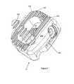
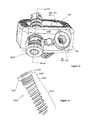
- FIG. 1is a perspective view of an implant assembly.
- FIG. 2Ais a top view of the assembly shown in FIG. 1 .
- FIG. 2Bis a side (lateral) view of the assembly shown in FIG. 1 .
- FIG. 2Cis a front view of the assembly shown in FIG. 1 .
- FIG. 3is a perspective view of the posterior body of the assembly shown in FIG. 1 .
- FIG. 4is a perspective view of the anterior body of the assembly shown in FIG. 1 .
- FIG. 5Ais a perspective view of one of the holes in the anterior body, viewed nearly along the hole axis.
- FIG. 5Bis an orthographic view of one of the holes in the anterior body, viewed nearly along the hole axis.
- FIG. 5Cis a similar view to that of FIG. 5B
- FIG. 6Ais a perspective view of one of the holes in the anterior body, viewed off-axis, illustrating one perimeter region being recessed relative to another perimeter region.
- FIG. 6Billustrates a hypothetical enveloping shape that displays the shape of the empty space within a portion of one of the holes in the anterior body.
- FIG. 7Ais a perspective view an embodiment of a screw.
- FIG. 7Bis a side view of the screw shown in FIG. 7A .
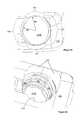
- FIG. 8Ais a perspective view of the screw head and the anterior body in a not-fully-engaged condition.
- FIG. 8Bis a partial cross-section of the embodiment shown in FIG. 8A .
- FIG. 8Cis a perspective view of the screw head and the anterior body in a fully-engaged condition.
- FIG. 8Dis a partial cross-section of the embodiment shown in FIG. 8C .
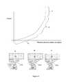
- FIG. 9is a graph illustrating how the torque needed to advance the screw varies as a function of position of the screw along the screw advancement path.
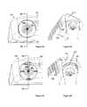
- FIG. 10Ais a perspective view of another embodiment of a screw.
- FIG. 10Bis a top view of the screw of the embodiment shown in FIG. 10A .
- FIG. 11is a perspective view of an anterior body and in particular the threads of that body.
- FIG. 12Ais a perspective view of the screw head and the anterior body in a not-fully-engaged condition.
- FIG. 12Bis a perspective cross-section the embodiment shown in FIG. 12A .
- FIG. 12Cis a perspective view of the screw head and the anterior body in a fully-engaged condition.
- FIG. 12Dis a perspective cross-section of FIG. 12C .
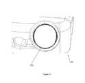
- FIG. 13is a perspective view of an assembly of another embodiment of the invention, having a hard-stop feature.
- FIG. 14is a perspective view of a screw shown in FIG. 13 .
- FIG. 15Ais a perspective sectional view of the embodiment shown in FIG. 13 , showing a screw that is only partially inserted into the implant assembly.
- FIG. 15Bis a perspective sectional view of the embodiment shown in FIG. 13 , showing a screw that is more completely inserted into the implant assembly as compared to what is shown in FIG. 15A .
- FIG. 15Cis a perspective sectional view of the embodiment shown in FIG. 13 , showing a screw that is completely inserted into the implant assembly.
- FIG. 16is a graph illustrating how the torque needed to advance the screw varies as a function of position of the screw along the screw advancement path, for the embodiment shown in FIG. 13 .
- FIG. 1The disclosed embodiments may further be understood with reference to FIG. 1 and to FIGS. 2 a , 2 b and 2 c .
- An embodimentis provided with an implant 10 that has a posterior body 100 and an anterior body 200 connected to each other. It can be understood that the designations anterior and posterior are only for purposes of description.
- the posterior body 100 and the anterior body 200may fit together.
- one or the other of the posterior body 100 and the anterior body 200may have a male feature and the other may have a complementary female feature.
- the posterior body 100 and the anterior body 200may fit together such that, together, they form an implant 10 that has an outside perimeter and encloses an open space 44 in the interior of the implant 10 .
- the outside perimeter of the implant 10may be smaller than, or approximately equal to, the enveloping outline of an intervertebral disc.
- the open interior space 44 of implant 10may be suitable to receive bone graft or bone growth promoting material or other material, in any combination desired by a surgeon.
- the combination of the posterior body 100 and the anterior body 200may have a first end face 80 a and a second end face 80 b opposed to the first end face 80 a .
- Either or both of these end faces 80 a , 80 bmay possess grooves 130 , 230 (as illustrated in FIG. 1 ), or alternatively, teeth, roughness or other similar features to discourage sliding or displacement of the assembly relative to adjacent vertebrae.
- the grooves 130 , 230 in the first end face 80 amay be substantially parallel to the grooves 130 , 230 in the second end face 80 b .
- the end faces 80 a , 80 bmay each have respective enveloping planes. The respective enveloping planes may be parallel to each other, or may be non-parallel to each other so as to provide a desired degree of lordosis.
- the anterior body 200may have two screw-holes 210 a , 210 b therethrough, suitable to receive screws. There may further be provided two screws (not shown in FIG. 3 or 4 ) that pass through the holes 210 a , 210 b in the anterior body 200 .
- the screw holes 210 a , 210 bmay have respective screw hole axes 212 a , 212 b , and may be symmetrically located with respect to a central plane of symmetry of the implant 10 .
- the orientation of the screw holes 210 a , 210 bmay be such that when the implant 10 is viewed from the side, as in FIG.
- the screws 300 a , 300 b and the screw hole axes 212 a , 212 bpoint away from each other such that one screw hole axis 212 a points toward a first vertebra and a second screw hole axis 212 B points toward a second vertebra that is different from and adjacent to the first vertebra.
- the orientation of screw-holes 210 a , 210 bmay be such that when the implant 10 is viewed from the top, as in FIG. 2 a , the screw hole axes 212 a , 212 b point slightly toward each other.
- the screw hole axes 212 a , 212 bas viewed in FIG. 2 a , to be located in planes are parallel to each other, or the screw hole axes 212 a , 212 b could have still other orientations.
- the anterior body 200may further possess a central hole 240 that may be appropriate for interface with an installation instrument or for use for other purposes.
- the anterior body 200may further possess an external groove 250 that also may be appropriate for interface with an installation instrument.
- the Central hole 240may be appropriately sized and oriented so as to permit injection of a substance therethrough or passage of a syringe therethrough.
- FIG. 3there is illustrated a posterior body 100 in isolation, and also showing dowel pins 500 .
- the dowel pins 500may form an interference fit with respect to the corresponding holes 172 in the posterior body 100 .
- the dowel pins 500may be a clearance fit with respect to the corresponding holes 172 in the posterior body 100 .
- the posterior body 100may have, on its cephalad-facing surface and on its caudal-facing surface, grooves 130 or ridges suitable to engage with bone 50 .
- Such grooves 130may be non-symmetric such that they may have a preferred direction so that inserting implant 10 into position in the surgical site is easier than withdrawing implant 10 from the surgical site.
- other forms of surface irregularitycould be used on the cephalad-facing and caudal-facing surface of posterior body 100 .
- the posterior body 100may be provided with a radiopaque marker that may be a metallic pin press-fitted into a corresponding hole 180 in the posterior body 100 . As illustrated, such a pin may be located in one or more planes of symmetry of the posterior body 100 .
- the posterior body 100may be made of, or possess, a polymer such as polyetheretherketone (PEEK).
- the anterior body 200is illustrated in isolation.
- the anterior body 200 and the posterior body 100need not be made of the same material.
- the anterior body 200may be made of a biocompatible metal such as titanium or a titanium alloy.
- the use of a metal for the anterior body 200may be suitable for the formation of internal threads and similar load-bearing features in the anterior body 200 .
- the anterior body 200may have an anterior face and a posterior face, two lateral sides, and a cephalad direction or axis and a caudal direction or axis. It may be understood that these directions or axes are for descriptive purposes only.
- the dowel pin 500may be either an interference fit or a clearance fit with hole 272 in anterior body 200 .
- the dowel pin 500may be provide an interference-fit in one or the other of the posterior body 100 and the anterior body 200 , and may be a clearance fit in the other of the posterior body 100 and the anterior body 200 .
- Dowel pins 500may be provided at each of two locations in the overall assembly. Details of the interference fit or clearance fit may be identical on the two opposite sides of the assembly, or alternatively they could be different.
- the dowel pins 500may be radiopaque.
- the dowel pin 500may form an interference fit with the corresponding holes in the anterior body 200 , and may form a clearance fit with the corresponding holes in the posterior body 100 .
- Another possibilityis that the dowel pin 500 may form an interference or friction fit with the corresponding holes in posterior body 100 , and may form a clearance fit with the corresponding holes in the anterior body 200 . In either of these situations, it is possible that there could be slight looseness in the joint between the posterior body 100 and the anterior body 200 .
- the dowel pins 500may form an interference fit both with the corresponding holes 172 in the posterior body 100 and with the corresponding holes 272 in the anterior body 200 . In such a configuration, there might be no looseness in the joint between the posterior body 100 and the anterior body 200 .
- the anterior body 200may have, on its cephalad-facing surface and on its caudal-facing surface, grooves suitable 230 to engage with bone 50 .
- Such grooves 230may be non-symmetric such that they may have a preferred direction so that inserting implant 10 into position in the surgical site is easier than withdrawing implant 10 from the surgical site.
- other forms of surface irregularitycould be used on the cephalad-facing and caudal-facing surface of the anterior body 200 .
- the anterior body 200may have a first hole 210 a and a second hole 210 b therethrough, with those holes having a respective first axis 212 a and a second axis 212 b .
- the first axis 212 a and the second axis 212 bmay be skew with respect to each other, i.e., not coplanar and not intersecting each other.
- the first hole 210 amay be to the left of anterior-posterior midplane and the second hole 210 B may be to the right of the midplane.
- the first hole axis 212 Amay point (looking posteriorly) partially in a cephalad direction
- the second hole axis 212 Bmay point (looking posteriorly) partially in a caudal direction.
- FIGS. 5A-6Bthere are shown close-up views of anterior body 200 in the immediate vicinity of the hole 210 B. Both FIGS. 5A and 5B are views approximately along the axis 212 B o the f hole 210 B.
- the screw hole 210 A, 210 B through the anterior body 200may, as illustrated, be a hole with an internal helical thread 220 .
- the thread 220may have uniform thread characteristics along the entire threaded length.
- the threads 220 of threaded hole 210 A, 210 Bcould be non-uniform in some sense.
- the threads 220may be of a constant pitch everywhere but could be tapered such that there is a larger opening dimension at the anterior face of the anterior body 200 and a smaller opening dimension away from the anterior face of the anterior body 200 .
- the holes 210 A, 210 Bmay also contain an entry region 270 that may be located adjacent to the thread 220 and be located closer to the front (anterior) surface of the anterior body 200 than is the thread 220 .
- Such an entry region 270may be unthreaded, such as a simple cylindrical hole that has an internal diameter that is larger than the root diameter of the hole 210 A, 210 B adjacent to the threads 220 .
- the entry region 270may be a chamfer of any desired chamfer angle, while again lying at a radial position larger than the radius of the root of the thread 220 .
- the perimeter of the hole 210 A, 210 Bmay possess four perimeter regions 261 , 262 , 263 , 264 in sequence around the perimeter.
- the perimeter regions 261 and 263may be opposed to each other, and the perimeter regions 262 and 264 may be opposed to each other.
- these four perimeter regions 261 , 262 , 263 , 264may not all be identical to each other.
- perimeter regionssuch as 262 , 264
- other perimeter regions, such as 261 , 263may have threads that are abbreviated in a radial direction, with the boundary of the perimeter regions 261 , 263 being at a radially larger location than the boundary of the perimeter regions 262 , 264 .
- perimeter regions 261 and 263are recessed such that a partial amount of the thread 220 is removed, but the removal does not extend all the way to the root of the thread 220 .
- the helical thread 220is continuous, but at recessed perimeter regions 261 , 263 the thread is partial.
- the threadis full or at least is fuller than in perimeter regions 261 , 263 .
- FIG. 6Billustrates a hypothetical envelope 280 of the space that is the interior of the threaded region 220 of the hole 210 A, 210 B.
- the dashed lines in FIG. 6Bare simply to help illustrate the shape.
- This envelope 280ignores the details of the threads 220 themselves and essentially indicates the envelope of space if the thread 220 was filled in or smoothed over; it can be considered that the illustrated envelope shape 280 connects the crests of the threads 220 .
- the cross-section of this envelope 280is non-circular and is different from the shape of the head of the screw 300 .
- the screw head 322would typically be circular although other shapes are possible. More descriptively, the cross-section of the envelope shape 280 contains, viewed from the exterior of this envelope shape 280 , both convex regions 288 and concave regions 289 .
- the screw 300may have a first threaded region 350 and a second threaded region 370 . It is also possible that there may be an unthreaded region 360 between the first threaded region 350 and the second threaded region 370 . However, the unthreaded region 360 is not essential.
- the screw 300may also have a tip region 380 that comes to a point.
- the screw 300may further be provided with a tool interface feature 386 , such as a hexalobe feature, in the head of the screw 300 , and may further possess a thread interruption 388 near the tip 380 so as to make the screw 300 able to self-tap into bone 50 .
- the crest of the thread 372is at an approximately constant radial dimension, but the root of the thread 372 lies along a taper.
- the unthreaded region 360typically would be approximately cylindrical.
- both the root and the crest of the thread 352may be tapered along a longitudinal axis of screw 300 , the first threaded region 350 may be shorter than the second threaded region 370 .
- the thread pitch of any external threadmay be defined as the distance, measured generally along an axial direction of the screw thread, from a first radially-outermost point to a second radially-outermost point that is exactly one rotation (360 degrees) away from the first radially-outermost point.
- the first threaded region 350may have a first thread pitch labeled in FIG. 7B as p350
- the second threaded region 370may have a second thread pitch labeled in FIG. 7B as p370.
- the thread pitch p370 on the bone-engaging second threaded region 370 of the screwmay be larger than the thread pitch p350 on the locking portion first threaded region 350 of the screw.
- the second threaded region (bone-engaging portion) 370 of the screwmay have a thread pitch of 1.25 mm, while the first threaded region (locking portion) 350 of the thread may have a thread pitch of 32 threads per inch, i.e., 0.8 mm.
- the screw 300may act to pull bone 50 into closer contact with the implant 10 .
- the first threaded region 350which may be tapered, may have dimensions appropriate so that when the screw 300 is sufficiently far advanced into the anterior body 200 , there is some geometric interference between the screw threads 352 and the internal threads 220 of the anterior body 200 . This interference may create a frictional restraint which discourages screw 300 from backing out of the implant 10 and of bone 50 .
- the interrelationship between the various partsmay be such that it requires a moderate amount of torque to advance the screw 300 into bone 50 when the threads 352 are not engaged with the anterior body 200 , but when the threads 352 are engaged with the internal threads 220 of the anterior body 200 , the required torque increases noticeably.
- the initial torquemay be associated with friction of the threads 372 against bone material 50 .
- the increased torquemay be associated with the interaction of the tapered threads 352 with the internal threads 220 in the anterior body 200 . This interaction may provide a frictional restraint to discourage the screw 300 from backing out of the anterior body 200 and of bone 50 , which may serve as a back-out prevention or secondary locking means.
- the entry region 270may be dimensioned so as to “hide” the head of the screw 300 within the envelope of the anterior body 200 , i.e., so that the head of the screw 300 does not protrude beyond an envelope or outline of the anterior body 200 . This may help to avoid irritating soft tissue in the patient's body. Also, as illustrated later herein, the presence of an entry region 270 may also help to emphasize the visual distinction of full engagement versus partial engagement, because at every point around the circumference there will be anterior body material available to contribute to the appearance. However, an entry region 270 is not essential.
- the interaction of the various described featuresmay be such as to provide a visual indication of when the screw 300 is sufficiently far advanced into the anterior body 200 to achieve geometric interference suitable to provide prevention of screw back-out.
- FIGS. 8A-8Dthere are shown two different configurations and appearances of the screw head and nearby material of the anterior body 200 , so as to provide a visual difference between the appearance of a fully-inserted screw configuration and the appearance of a partially-inserted configuration.
- the visible region 356may be substantially circular and may have a radius R2 to its edge.
- the screw 300is positioned such that screw head 322 has not yet entered the thread 220 and therefore the screw head 322 is in entry region 270 and thus the entire screw head 322 is visible, in this case, as a circular shape.
- the screw thread 352 of the threaded region 350is only loosely engaged, if engaged at all, with the corresponding portion of thread 220 .
- the visible region 366may be generally non-circular and may resemble the cross-sectional shape of the envelope shape 280 .
- the screw thread 352 of the threaded region 350is tightly engaged with the corresponding portion of the thread 220 .
- FIG. 8Dit can be seen that the entire head 322 of the screw 300 has already entered the thread 220 , and therefore the appearance of the head 322 is determined in part by the presence of the thread 220 .
- FIG. 8Dalthough being a cross-section of the embodiment shown in FIG.
- the visible region 366may include, at various different angular positions, a compact portion 366 a (in two places, as illustrated) and an expanded portion 366 b (in two places, as illustrated).
- the compact portion 366 amay be bounded by circular arcs having a radius R1.
- the expanded portion 366 bmay include a region located at a radial location greater than radius R1.
- the expanded portion 316 bmay itself be bounded by a circular arc having a radius R2, with radius R2 being greater than radius R1.
- the outer boundary of the expanded portion 316 bactually be a circular arc; other shapes are also possible as long as they include material located at a radial location greater than radius R1. It is also possible that the quantity of each region ( 366 a , 366 b ) could be as few as one, or could be greater than two. It is also possible that the boundary of the compact portion 366 a could be something other than a circular arc. It also is possible that the boundary of the expanded portion 366 b could be something other than a circular arc. In contrast to FIG. 8A , FIG. 8C is such that the perimeter of observed shape 366 contains places at which two segments of the perimeter meet at a sharp corner, i.e., a fairly abrupt change. Also, the observed shape 366 , as viewed from its exterior contains some convex portions and some concave portions (in this case, the corners being the concavities). This corresponds to the description given in connection with envelope 280 in FIG. 6B .
- FIG. 9there is illustrated a relation of torque needed to advance the screw 300 , as a function of position of the screw 300 relative to the anterior body 200 or more generally implant 10 .
- region A of FIG. 9there is no contact between the screw thread 350 and the anterior body internal thread 220 , so whatever torque is needed to advance the screw 300 results only from interaction of the screw 300 with bone 50 , such as by friction.
- Such torquecan be expected to slightly increase as the screw 300 advances into bone 50 .
- region Bthe screw thread 350 contacts the anterior body internal thread 220 , and as the screw 300 advances into bone 50 additional friction results from the taper of at least one of those threads.
- the torque in Region Bis palpably different from the torque in Region A and also that the torque in Region B increases more rapidly (for example, two or three or more times more rapidly) as a function of advancing the screw position than is the case in Region A. This may especially be the case due to the taper that may exist on at least one of the screw hole internal thread 220 and the external thread 350 . Thus, passage from region A into region B may be sensed in a tactile manner by the surgeon who is turning the screw.
- an embodiment of the inventionprovides verifying or detecting the achievement of back-out prevention in two different independent ways.
- the implant 10may be provided with a posterior body 1100 and an anterior body 1200 , with the anterior body 1200 having internal threads 1220 .
- the internal threads 1220may be helical threads that are substantially identical at various places around the helix, without a recess into the threads such as was provided in an earlier embodiment herein.
- the screw 1300( FIGS. 10A and 10B ) has a screw head 1322 and has at least one indentation 1390 at a periphery of the screw head 1322 . As illustrated, there are three such indentations 1390 . Aside from the presence of the indentation(s) 1390 , the periphery of the screw head 1322 may possess at least one circular arc and may be substantially rounded. Despite the presence of the indentation(s) 1390 , the screw head 1322 may be substantially rigid.
- FIG. 12A-12Dthere are shown two different configurations and appearances of the screw head 1322 and nearby material of anterior body 1200 , so as to provide a visual contrast between the appearance of a fully-inserted screw configuration and the appearance of a partially-inserted configuration.
- the visible region 1356may be something other than a perfect circle, such as a circle with one or more indentations 1390 in its outer periphery.
- the head 1322 of screw 1300has not yet entered the threads 1220 in the anterior body 1200 . Therefore, what is visible is the entire periphery of the head 1322 of screw 1300 , including indentations 1390 .
- the screw thread 1352 of the threaded region 1350is only loosely engaged, if engaged at all, with the corresponding portion of the thread 1220 .
- the visible region 1366may be generally circular.
- the screw thread 1352 of the threaded region 1350is tightly engaged with the corresponding portion of the thread 1220 .
- the head 1322 of the screw 1300has already entered the threads 1220 in the anterior body 1200 , with the result that what is visible is a circular region defined substantially by the crests of the threads 1220 , and indentations 1390 in head 1322 of screw 1300 are hidden within the threads 1220 and are not visible.
- the radial distance from the longitudinal axis of the screw 1300 to the radially-innermost point of indentation 1390may be greater than the radial distance from the longitudinal axis of the hole 1320 to the crest of the thread 1220 . In this way, when the screw 1300 is fully engaged with the anterior body 1200 , the indentation 1390 can be “hidden” by the thread 1220 .
- an implant 10as a single unitary component.
- Such unitary componentcould be made of either polymer or metal, as desired.
- the frictional back-out preventioncan be accomplished if the external thread 350 is tapered whether or not the internal thread 220 is tapered.
- the internal thread 220has been illustrated as being uniform in pitch and as having constant major diameter (other than having material partially cut away in certain places for recessed perimeter regions 261 , 263 ). However, it is also possible that the internal thread 220 could be tapered in a way that corresponds at least approximately to the taper of the external thread 350 , in a way that resembles threads used in pipe for conventional plumbing fittings. It can further be appreciated that frictional back-out prevention can be accomplished if the internal thread 220 is tapered while the external thread 350 is of constant diameter.
- the visible shape of the screw head for non-engagementcould be circular, while the visible shape of the screw head for engagement could more generally be any non-circular shape.
- the shape illustrated in FIG. 8Cmay be a shape that is particularly easy to distinguish from the non-fully-engaged shape, because of the presence of sharp corners in the engaged shape.
- a shape of the visible screw head that indicates engagement of back-out prevention and is easily recognizablecould be any shape such that (viewed from the outside of the shape) has convex curvature in some places on its perimeter and concave curvature in other places on its perimeter.
- the places of convex curvatureare the generally long generally circular arcs, and the places of concave curvature are the relatively sharp corners.
- the visible shape during non-engagementmay be circular, and the visible shape during engagement may be generally non-circular.
- the visible shape during non-engagementmay be the full outline shape of the screw head (with the full outline shape of the screw head possibly being circular but not necessarily being circular), and the visible shape during engagement may be a shape that is different from the full outline shape of the screw head.
- the visible shape during non-engagementmay be the full outline shape of the screw head such that the full outline shape of the screw head a modification of a circle with the modification being at least one recess, and the visible shape during engagement may be circular.
- the posterior body 100makes up a somewhat larger portion of the implant 10 than does the anterior body 200 .
- the implant 10could be made as a single piece.
- the indentation 1390could be any of various depths along the axis of the screw 1300 . As illustrated, the indentations 1390 extend until there no longer is any intersection of the indentations 1390 with the thread 1350 , but the axial extent of the indentations 1390 could be shorter if desired.
- the recess 261 , 263could be any of various depths along the axis of the screw 300 . As illustrated, the recesses 261 , 263 extend along the full length of the thread 220 , but the axial extent could be partial if desired.
- a kit of parts provided for use by a surgeonmay provide a “rescue” screw in addition to the nominal screw.
- the nominal screwmay have a bone-engaging thread 370 whose maximum outside diameter is smaller than the inside diameter of the threads 220 of hole 210 A, 210 B, thereby allowing easy passage of the screw portion 370 through the hole 210 A, 210 B.
- the rescue screwmay have a bone-engaging thread 372 whose maximum outside diameter is also smaller than the inside diameter of the threads 220 of hole 210 A, 210 B, but is larger than the maximum outside diameter of the nominal screw.
- features described hereincan be used in connection with cervical vertebrae, lumbar vertebrae and generally any vertebrae, and also can be used in application to bone fixation devices for use with bones other than vertebrae.
- the illustrationsshow an implant that possesses only two screws, embodiments of the invention can possess four screws, three screws, or in general any number of screws.
- An embodiment of the inventioncan also be described as a surgical method that uses any of the described devices.
- a screw 2300may be provided having a hard stop feature such that when the screw 2300 is advanced sufficiently far with respect to the anterior body 200 , the hard stop feature on the screw 2300 comes in contact with a corresponding feature on the anterior body 200 , such that that contact substantially prevents any further advancement of the screw 2300 with respect to anterior body 200 .
- the hard stop featuremay provide a counter-bore 276 in the anterior body 200 , with the counter-bore 276 having a flat bottom.
- the screw head 2320may have a lip 2322 having a lip outside diameter.
- the screw 2300may further be provided with a first threaded region 2350 and a second threaded region 2370 , and optionally an unthreaded region 2360 between the first threaded region 2350 and the second threaded region 2370 .
- the first threaded region 2350may be tapered so as to engage with the corresponding thread 220 of the anterior body 200 to produce friction preventing or resisting back-out of the screw 2320 from the anterior body 220 .
- the lip 2322may be located more proximally than any of the other features of the screw 2300 .
- the outside diameter of the lip 2322may be larger than the crest diameter of the thread of the screw 2300 , or larger than the root diameter of the threads of the threaded region 2350 of the screw 2300 .
- the lip 2322may, as illustrated, have a lower (distal) surface that lies in a plane that is approximately perpendicular to a longitudinal axis of the screw 2300 .
- other angles for the distal surface of the head 2320are also possible, as long as they provide a hard stop by interaction with the anterior body 200 .
- the lip 2322may cooperate with an internal feature of the anterior body 200 such as the counter-bore 276 to provide a hard stop that makes it substantially impossible for the screw 2300 to advance beyond a defined stop or limit.
- the lip 2322may have an outside diameter that is larger than a corresponding dimension of a feature that the lip 2322 comes into contact with.
- FIGS. 15A-15CVarious stages of interaction of the screw 2300 with the anterior body 200 are illustrated in FIGS. 15A-15C , and also in the pictorial portions of FIG. 16 .
- FIG. 15Awhich depicts a screw that is only partially inserted into the implant assembly
- the screw 2300would interact with bone but the threads of region 2350 do not yet interact with the corresponding internal threads of anterior the body 200 .
- FIG. 15Bwhich depicts a screw that is further inserted into the implant assembly
- the screw 2300would again interact with bone but the threads of region 2350 also interact with the corresponding internal threads of the anterior body 200 .
- FIG. 15Cillustrates a configuration in which the lip 2322 directly contacts a corresponding facing feature of the anterior body 200 .
- Such facing featurecould be a counter-bore 276 having a flat bottom.
- FIGS. 15A , 15 B and 15 Calso correspond to regions A and B and C as illustrated in FIG. 16 .
- FIG. 16is a description of the relation of torque needed to advance the screw 2300 , as a function of position of the screw 2300 relative to the anterior body 200 or more generally the implant 10 .
- the characteristic illustrated in FIG. 16has a first or “A” region similar to what was illustrated in FIG. 9 , and a second or “B” region as also similar to what was illustrated in FIG. 9 .
- FIG. 16shows a third or “C” region such that it is simply not possible for the screw 2300 to advance beyond a defined limit with respect to the anterior body 200 , no matter how much torque is applied to the screw 2300 .
- the “C” region of the characteristic graphis substantially vertical. This is further illustrated in the pictorial portion of FIG. 16 , for condition C, in which the lip 2322 directly contacts a corresponding feature of the anterior body 200 to form such a limit.
- inventive embodimentsare presented by way of example only and that, within the scope of the appended claims and equivalents thereto, inventive embodiments may be practiced otherwise than as specifically described and claimed.
- inventive embodiments of the present disclosureare directed to each individual feature, system, article, material, kit, and/or method described herein.
- a reference to “A and/or B”, when used in conjunction with open-ended language such as “comprising”can refer, in one embodiment, to A only (optionally including elements other than B); in another embodiment, to B only (optionally including elements other than A); in yet another embodiment, to both A and B (optionally including other elements); etc.
- the phrase “at least one,” in reference to a list of one or more elements,should be understood to mean at least one element selected from any one or more of the elements in the list of elements, but not necessarily including at least one of each and every element specifically listed within the list of elements and not excluding any combinations of elements in the list of elements.
- This definitionalso allows that elements may optionally be present other than the elements specifically identified within the list of elements to which the phrase “at least one” refers, whether related or unrelated to those elements specifically identified.
- “at least one of A and B”can refer, in one embodiment, to at least one, optionally including more than one, A, with no B present (and optionally including elements other than B); in another embodiment, to at least one, optionally including more than one, B, with no A present (and optionally including elements other than A); in yet another embodiment, to at least one, optionally including more than one, A, and at least one, optionally including more than one, B (and optionally including other elements); etc.
Landscapes
- Health & Medical Sciences (AREA)
- Engineering & Computer Science (AREA)
- Biomedical Technology (AREA)
- Neurology (AREA)
- Orthopedic Medicine & Surgery (AREA)
- Cardiology (AREA)
- Oral & Maxillofacial Surgery (AREA)
- Transplantation (AREA)
- Heart & Thoracic Surgery (AREA)
- Vascular Medicine (AREA)
- Life Sciences & Earth Sciences (AREA)
- Animal Behavior & Ethology (AREA)
- General Health & Medical Sciences (AREA)
- Public Health (AREA)
- Veterinary Medicine (AREA)
- Prostheses (AREA)
- Surgical Instruments (AREA)
Abstract
Description
Claims (22)
Priority Applications (1)
| Application Number | Priority Date | Filing Date | Title |
|---|---|---|---|
| US13/211,872US8753396B1 (en) | 2010-09-13 | 2011-08-17 | Intervertebral implant having back-out prevention feature |
Applications Claiming Priority (2)
| Application Number | Priority Date | Filing Date | Title |
|---|---|---|---|
| US38229410P | 2010-09-13 | 2010-09-13 | |
| US13/211,872US8753396B1 (en) | 2010-09-13 | 2011-08-17 | Intervertebral implant having back-out prevention feature |
Publications (1)
| Publication Number | Publication Date |
|---|---|
| US8753396B1true US8753396B1 (en) | 2014-06-17 |
Family
ID=50896751
Family Applications (1)
| Application Number | Title | Priority Date | Filing Date |
|---|---|---|---|
| US13/211,872Active2031-12-09US8753396B1 (en) | 2010-09-13 | 2011-08-17 | Intervertebral implant having back-out prevention feature |
Country Status (1)
| Country | Link |
|---|---|
| US (1) | US8753396B1 (en) |
Cited By (31)
| Publication number | Priority date | Publication date | Assignee | Title |
|---|---|---|---|---|
| CN105266927A (en)* | 2014-07-25 | 2016-01-27 | 吴爱悯 | Double-skewed slot intervertebral fusion device adapted for cervical pedicle cervical disc oblique screw |
| US20160058480A1 (en)* | 2014-09-03 | 2016-03-03 | Aesculap Implant Systems, Llc | Fastener, spinal interbody system including same and method |
| US20160081818A1 (en)* | 2013-10-07 | 2016-03-24 | Warsaw Orthopedic, Inc. | Spinal implant system and method for lumbar and lumbosacral fusion |
| US9522069B1 (en)* | 2007-07-02 | 2016-12-20 | Theken Spine, Llc | Spinal cage having deployable member |
| US10342674B2 (en) | 2007-07-02 | 2019-07-09 | Theken Spine, Llc | Spinal cage having deployable member |
| US10736752B1 (en) | 2017-10-24 | 2020-08-11 | Omnia Medical, LLC | Multi-material multi-component spinal implant |
| US11285014B1 (en) | 2020-11-05 | 2022-03-29 | Warsaw Orthopedic, Inc. | Expandable inter-body device, system, and method |
| US11291554B1 (en) | 2021-05-03 | 2022-04-05 | Medtronic, Inc. | Unibody dual expanding interbody implant |
| KR102384957B1 (en)* | 2021-08-10 | 2022-04-11 | 주식회사 제일메디칼코퍼레이션 | An intervertebral fusion prosthesis that is self-supporting and has a screw thread to prevent the screw from coming off |
| US11376134B1 (en) | 2020-11-05 | 2022-07-05 | Warsaw Orthopedic, Inc. | Dual expanding spinal implant, system, and method of use |
| US11395743B1 (en) | 2021-05-04 | 2022-07-26 | Warsaw Orthopedic, Inc. | Externally driven expandable interbody and related methods |
| US11517363B2 (en) | 2020-11-05 | 2022-12-06 | Warsaw Orthopedic, Inc. | Screw driver and complimentary screws |
| US11517443B2 (en) | 2020-11-05 | 2022-12-06 | Warsaw Orthopedic, Inc. | Dual wedge expandable implant, system and method of use |
| US11612499B2 (en) | 2021-06-24 | 2023-03-28 | Warsaw Orthopedic, Inc. | Expandable interbody implant |
| US11638653B2 (en) | 2020-11-05 | 2023-05-02 | Warsaw Orthopedic, Inc. | Surgery instruments with a movable handle |
| US11730608B2 (en) | 2021-07-13 | 2023-08-22 | Warsaw Orthopedic, Inc. | Monoblock expandable interbody implant |
| US11766339B1 (en) | 2017-10-24 | 2023-09-26 | Omnia Medical, LLC | Multi-material multi-component spinal implant |
| US11806250B2 (en) | 2018-02-22 | 2023-11-07 | Warsaw Orthopedic, Inc. | Expandable spinal implant system and method of using same |
| US11833059B2 (en) | 2020-11-05 | 2023-12-05 | Warsaw Orthopedic, Inc. | Expandable inter-body device, expandable plate system, and associated methods |
| US11850163B2 (en) | 2022-02-01 | 2023-12-26 | Warsaw Orthopedic, Inc. | Interbody implant with adjusting shims |
| US11963881B2 (en) | 2020-11-05 | 2024-04-23 | Warsaw Orthopedic, Inc. | Expandable inter-body device, system, and method |
| US12064354B2 (en) | 2020-09-24 | 2024-08-20 | Alphatec Spine, Inc. | Composite porous interbodies and methods of manufacture |
| US12121453B2 (en) | 2020-11-05 | 2024-10-22 | Warsaw Orthopedic, Inc. | Dual wedge expandable implant with eyelets, system, and method of use |
| US12171439B2 (en) | 2020-11-05 | 2024-12-24 | Warsaw Orthopedic, Inc. | Protected drill |
| US12186201B2 (en) | 2007-07-02 | 2025-01-07 | Theken Spine, Llc | Spinal cage having deployable member |
| US12239544B2 (en) | 2020-11-05 | 2025-03-04 | Warsaw Orthopedic, Inc. | Rhomboid shaped implants |
| US12268614B2 (en) | 2021-06-24 | 2025-04-08 | Warsaw Orthopedic, Inc. | Interbody implant with adjusting shims |
| US12295865B2 (en) | 2021-06-24 | 2025-05-13 | Warsaw Orthopedic, Inc. | Expandable interbody implant and corresponding inserter |
| US12318308B2 (en) | 2020-11-05 | 2025-06-03 | Warsaw Orthopedic, Inc. | Dual expandable inter-body device |
| US12414863B2 (en) | 2021-06-24 | 2025-09-16 | Warsaw Orthopedic, Inc. | Expandable interbody implant and corresponding surgical tool |
| US12440349B2 (en) | 2022-02-04 | 2025-10-14 | Warsaw Orthopedic, Inc. | Expandable interbody implant and breakoff screw |
Citations (128)
| Publication number | Priority date | Publication date | Assignee | Title |
|---|---|---|---|---|
| US5120171A (en) | 1990-11-27 | 1992-06-09 | Stuart Surgical | Bone screw with improved threads |
| US5258031A (en) | 1992-01-06 | 1993-11-02 | Danek Medical | Intervertebral disk arthroplasty |
| US5275601A (en) | 1991-09-03 | 1994-01-04 | Synthes (U.S.A) | Self-locking resorbable screws and plates for internal fixation of bone fractures and tendon-to-bone attachment |
| US5364399A (en) | 1993-02-05 | 1994-11-15 | Danek Medical, Inc. | Anterior cervical plating system |
| US5403136A (en) | 1991-06-25 | 1995-04-04 | Synthes (U.S.A.) | Threaded fastener especially for orthopaedic purposes |
| US5520690A (en) | 1995-04-13 | 1996-05-28 | Errico; Joseph P. | Anterior spinal polyaxial locking screw plate assembly |
| US5531554A (en) | 1993-11-05 | 1996-07-02 | Jbs S.A. | Self-retaining means for fasteners particularly screws |
| US5536127A (en) | 1994-10-13 | 1996-07-16 | Pennig; Dietmar | Headed screw construction for use in fixing the position of an intramedullary nail |
| US5549612A (en) | 1992-11-25 | 1996-08-27 | Codman & Shurtleff, Inc. | Osteosynthesis plate system |
| US5578034A (en) | 1995-06-07 | 1996-11-26 | Danek Medical, Inc. | Apparatus for preventing screw backout in a bone plate fixation system |
| US5601553A (en) | 1994-10-03 | 1997-02-11 | Synthes (U.S.A.) | Locking plate and bone screw |
| US5709686A (en) | 1995-03-27 | 1998-01-20 | Synthes (U.S.A.) | Bone plate |
| US5931838A (en) | 1997-01-28 | 1999-08-03 | Vito; Raymond P. | Fixation assembly for orthopedic applications |
| US5954722A (en) | 1997-07-29 | 1999-09-21 | Depuy Acromed, Inc. | Polyaxial locking plate |
| US5964768A (en) | 1993-01-21 | 1999-10-12 | Acumed, Inc. | Tapered bone screw with continuously varying pitch |
| US6017345A (en) | 1997-05-09 | 2000-01-25 | Spinal Innovations, L.L.C. | Spinal fixation plate |
| US6030389A (en) | 1997-08-04 | 2000-02-29 | Spinal Concepts, Inc. | System and method for stabilizing the human spine with a bone plate |
| US6129730A (en) | 1999-02-10 | 2000-10-10 | Depuy Acromed, Inc. | Bi-fed offset pitch bone screw |
| US6139550A (en) | 1997-02-11 | 2000-10-31 | Michelson; Gary K. | Skeletal plating system |
| US6152927A (en) | 1997-05-15 | 2000-11-28 | Sdgi Holdings, Inc. | Anterior cervical plating system |
| US6156037A (en) | 1998-10-28 | 2000-12-05 | Sdgi Holdings, Inc. | Anterior lateral spine cage-plate fixation device and technique |
| US6193721B1 (en) | 1997-02-11 | 2001-02-27 | Gary K. Michelson | Multi-lock anterior cervical plating system |
| US6224602B1 (en) | 1999-10-11 | 2001-05-01 | Interpore Cross International | Bone stabilization plate with a secured-locking mechanism for cervical fixation |
| US6235059B1 (en) | 1996-04-03 | 2001-05-22 | Scient'x (Societe A Responsabilite Limitee) | Intersomatic setting and fusion system |
| US6258089B1 (en) | 1998-05-19 | 2001-07-10 | Alphatec Manufacturing, Inc. | Anterior cervical plate and fixation system |
| US6306140B1 (en) | 2001-01-17 | 2001-10-23 | Synthes (Usa) | Bone screw |
| US6306139B1 (en) | 1998-10-19 | 2001-10-23 | Scint'x | Intervertebral connection device with an anti-extraction device to prevent extraction of anchoring screws |
| US6331179B1 (en) | 2000-01-06 | 2001-12-18 | Spinal Concepts, Inc. | System and method for stabilizing the human spine with a bone plate |
| US6355043B1 (en) | 1999-03-01 | 2002-03-12 | Sulzer Orthopedics Ltd. | Bone screw for anchoring a marrow nail |
| US6358250B1 (en) | 2000-02-01 | 2002-03-19 | Hand Innovations, Inc. | Volar fixation system |
| US6413259B1 (en) | 2000-12-14 | 2002-07-02 | Blackstone Medical, Inc | Bone plate assembly including a screw retaining member |
| US6432106B1 (en) | 1999-11-24 | 2002-08-13 | Depuy Acromed, Inc. | Anterior lumbar interbody fusion cage with locking plate |
| US6440135B2 (en) | 2000-02-01 | 2002-08-27 | Hand Innovations, Inc. | Volar fixation system with articulating stabilization pegs |
| US6454769B2 (en) | 1997-08-04 | 2002-09-24 | Spinal Concepts, Inc. | System and method for stabilizing the human spine with a bone plate |
| US6458133B1 (en) | 2000-12-19 | 2002-10-01 | Chih-I Lin | Spinal fixation and retrieval device |
| US6533786B1 (en) | 1999-10-13 | 2003-03-18 | Sdgi Holdings, Inc. | Anterior cervical plating system |
| US6554863B2 (en) | 1998-08-03 | 2003-04-29 | Synthes | Intervertebral allograft spacer |
| US6558423B1 (en) | 1999-05-05 | 2003-05-06 | Gary K. Michelson | Interbody spinal fusion implants with multi-lock for locking opposed screws |
| US6572619B2 (en) | 2001-02-23 | 2003-06-03 | Albert N. Santilli | Cage plate for spinal fusion and method of operation |
| US6575975B2 (en) | 2000-04-19 | 2003-06-10 | Synthes (U.S.A.) | Bone fixation method |
| US6585740B2 (en) | 1998-11-26 | 2003-07-01 | Synthes (U.S.A.) | Bone screw |
| US6599290B2 (en) | 2001-04-17 | 2003-07-29 | Ebi, L.P. | Anterior cervical plating system and associated method |
| US6602256B1 (en) | 1999-10-11 | 2003-08-05 | Cross Medical Products, Inc. | Bone stabilization plate with a secured-locking mechanism for cervical fixation |
| US6602255B1 (en) | 2000-06-26 | 2003-08-05 | Stryker Spine | Bone screw retaining system |
| US6623486B1 (en) | 1999-09-13 | 2003-09-23 | Synthes (U.S.A.) | bone plating system |
| US6656181B2 (en) | 2000-11-22 | 2003-12-02 | Robert A Dixon | Method and device utilizing tapered screw shanks for spinal stabilization |
| US6669701B2 (en) | 2000-01-27 | 2003-12-30 | Synthes (Usa) | Bone plate |
| US6695846B2 (en) | 2002-03-12 | 2004-02-24 | Spinal Innovations, Llc | Bone plate and screw retaining mechanism |
| US6695845B2 (en) | 2000-10-16 | 2004-02-24 | Robert A Dixon | Method and apparatus utilizing interference fit screw shanks for nonmetallic spinal stabilization |
| US6702817B2 (en) | 2001-01-19 | 2004-03-09 | Aesculap Ag & Co. Kg | Locking mechanism for a bone screw |
| US6706046B2 (en) | 2000-02-01 | 2004-03-16 | Hand Innovations, Inc. | Intramedullary fixation device for metaphyseal long bone fractures and methods of using the same |
| US6716247B2 (en) | 2000-02-04 | 2004-04-06 | Gary K. Michelson | Expandable push-in interbody spinal fusion implant |
| US6730127B2 (en) | 2000-07-10 | 2004-05-04 | Gary K. Michelson | Flanged interbody spinal fusion implants |
| US6730090B2 (en) | 2000-02-01 | 2004-05-04 | Hand Innovations, Inc. | Fixation device for metaphyseal long bone fractures |
| US6749636B2 (en) | 2001-04-02 | 2004-06-15 | Gary K. Michelson | Contoured spinal fusion implants made of bone or a bone composite material |
| US6808537B2 (en) | 2000-07-07 | 2004-10-26 | Gary Karlin Michelson | Expandable implant with interlocking walls |
| US6821278B2 (en) | 2000-06-26 | 2004-11-23 | Synthes Ag Chur | Bone plate |
| US6866665B2 (en) | 2003-03-27 | 2005-03-15 | Hand Innovations, Llc | Bone fracture fixation system with subchondral and articular surface support |
| US6878167B2 (en) | 2002-04-24 | 2005-04-12 | Bret A. Ferree | Methods and apparatus for placing intradiscal devices |
| US20050085913A1 (en) | 2003-03-31 | 2005-04-21 | Robert Fraser | Spinal fixation plate |
| US6884242B2 (en) | 2001-04-06 | 2005-04-26 | Society De Fabrication De Materiel Orthopedique, S.A. | Anterior plating system and method |
| US6893444B2 (en) | 2000-02-01 | 2005-05-17 | Hand Innovations, Llc | Bone fracture fixation systems with both multidirectional and unidirectional stabilization pegs |
| US6896701B2 (en) | 2001-01-22 | 2005-05-24 | Sdgi Holdings, Inc. | Modular interbody fusion implant |
| US6921403B2 (en) | 2000-02-16 | 2005-07-26 | Trans1 Inc. | Method and apparatus for spinal distraction and fusion |
| US20050192578A1 (en) | 2004-02-26 | 2005-09-01 | Horst Steven P. | Bone plates with locking apertures |
| US6955677B2 (en) | 2002-10-15 | 2005-10-18 | The University Of North Carolina At Chapel Hill | Multi-angular fastening apparatus and method for surgical bone screw/plate systems |
| US6962606B2 (en) | 2000-02-04 | 2005-11-08 | Gary Karlin Michelson | Expandable push-in interbody spinal fusion implant |
| US6972019B2 (en) | 2001-01-23 | 2005-12-06 | Michelson Gary K | Interbody spinal implant with trailing end adapted to receive bone screws |
| US6984234B2 (en) | 2003-04-21 | 2006-01-10 | Rsb Spine Llc | Bone plate stabilization system and method for its use |
| US6986788B2 (en) | 1998-01-30 | 2006-01-17 | Synthes (U.S.A.) | Intervertebral allograft spacer |
| US6989031B2 (en) | 2001-04-02 | 2006-01-24 | Sdgi Holdings, Inc. | Hemi-interbody spinal implant manufactured from a major long bone ring or a bone composite |
| US7001389B1 (en) | 2002-07-05 | 2006-02-21 | Navarro Richard R | Fixed and variable locking fixation assembly |
| US7008426B2 (en) | 2001-12-14 | 2006-03-07 | Paul Kamaljit S | Bone treatment plate assembly |
| US7018416B2 (en) | 2000-07-06 | 2006-03-28 | Zimmer Spine, Inc. | Bone implants and methods |
| US20060085071A1 (en) | 2003-02-06 | 2006-04-20 | Beat Lechmann | Intervertebral implant |
| US7041105B2 (en) | 2001-06-06 | 2006-05-09 | Sdgi Holdings, Inc. | Dynamic, modular, multilock anterior cervical plate system having detachably fastened assembleable and moveable segments |
| US7044952B2 (en) | 2001-06-06 | 2006-05-16 | Sdgi Holdings, Inc. | Dynamic multilock anterior cervical plate system having non-detachably fastened and moveable segments |
| US7044953B2 (en) | 2003-02-27 | 2006-05-16 | Stryker Leibinger Gmbh & Co. Kg | Compression bone screw |
| US7048739B2 (en) | 2002-12-31 | 2006-05-23 | Depuy Spine, Inc. | Bone plate and resilient screw system allowing bi-directional assembly |
| US7070599B2 (en) | 2002-07-24 | 2006-07-04 | Paul Kamaljit S | Bone support assembly |
| US7087082B2 (en) | 1998-08-03 | 2006-08-08 | Synthes (Usa) | Bone implants with central chambers |
| US7097645B2 (en) | 2001-06-04 | 2006-08-29 | Sdgi Holdings, Inc. | Dynamic single-lock anterior cervical plate system having non-detachably fastened and moveable segments |
| US7104991B2 (en) | 2001-02-27 | 2006-09-12 | Robert A Dixon | Method and device for using extended interference fit screw shanks for spinal stabilization |
| US7112222B2 (en) | 2003-03-31 | 2006-09-26 | Depuy Spine, Inc. | Anterior lumbar interbody fusion cage with locking plate |
| US20060241763A1 (en) | 1998-08-03 | 2006-10-26 | Synthes (Usa) | Multipiece bone implant |
| US7172627B2 (en) | 2001-04-03 | 2007-02-06 | Scient'x | Stabilized interbody fusion system for vertebrae |
| US7175623B2 (en) | 2002-06-24 | 2007-02-13 | Lanx, Llc | Cervical plate with backout protection |
| US7179260B2 (en) | 2003-09-29 | 2007-02-20 | Smith & Nephew, Inc. | Bone plates and bone plate assemblies |
| US7182782B2 (en) | 2003-09-30 | 2007-02-27 | X-Spine Systems, Inc. | Spinal fusion system and method for fusing spinal bones |
| US7186256B2 (en) | 2001-06-04 | 2007-03-06 | Warsaw Orthopedic, Inc. | Dynamic, modular, single-lock anterior cervical plate system having assembleable and movable segments |
| US7229445B2 (en) | 2004-06-21 | 2007-06-12 | Synthes (Usa) | Bone plate with bladed portion |
| US7255699B2 (en) | 2001-12-14 | 2007-08-14 | Paul Kamaljit S | Spinal plate assembly |
| US7273481B2 (en) | 2002-10-28 | 2007-09-25 | Blackstone Medical, Inc. | Bone plate assembly provided with screw locking mechanisms |
| US7278997B1 (en) | 2003-03-07 | 2007-10-09 | Theken Spine, Llc | Instrument guide and implant holder |
| US7282053B2 (en) | 2003-03-27 | 2007-10-16 | Depuy Products, Inc. | Method of using fracture fixation plate for performing osteotomy |
| US20070250167A1 (en) | 2003-04-21 | 2007-10-25 | Rsb Spine Llc | Spine implants |
| US7288094B2 (en) | 2005-06-10 | 2007-10-30 | Sdgi Holdings, Inc. | System and method for retaining screws relative to a vertebral plate |
| US7288095B2 (en) | 2004-08-12 | 2007-10-30 | Atlas Spine, Inc. | Bone plate with screw lock |
| US7306605B2 (en) | 2003-10-02 | 2007-12-11 | Zimmer Spine, Inc. | Anterior cervical plate |
| US7309340B2 (en) | 2003-06-20 | 2007-12-18 | Medicinelodge, Inc. | Method and apparatus for bone plating |
| US7311712B2 (en) | 2004-02-26 | 2007-12-25 | Aesculap Implant Systems, Inc. | Polyaxial locking screw plate assembly |
| US7322984B2 (en) | 2005-01-06 | 2008-01-29 | Spinal, Llc | Spinal plate with internal screw locks |
| US7322983B2 (en) | 2002-02-12 | 2008-01-29 | Ebi, L.P. | Self-locking bone screw and implant |
| US20080177307A1 (en) | 2005-04-12 | 2008-07-24 | Moskowitz Ahmnon D | Bi-directional fixating/locking transvertebral body screw/intervertebral cage stand-alone constructs and posterior cervical and lumbar interarticulating joint stapling guns and devices for spinal fusion |
| US20080249625A1 (en) | 2007-04-03 | 2008-10-09 | Warsaw Orthopedic, Inc. | Composite Interbody Spacer |
| US20080312742A1 (en) | 2007-06-12 | 2008-12-18 | Dennis Lee Abernathie | Anterior Spinal Fusion and Fixation Cage with Integrated Plate and Method of Use |
| US20090024170A1 (en)* | 2007-07-16 | 2009-01-22 | X-Spine Systems, Inc. | Implant plate screw locking system and screw having a locking member |
| US20090105830A1 (en) | 2007-06-06 | 2009-04-23 | Jones Robert J | Interbody fusion device, integral retention device, and associated methods |
| US7527640B2 (en) | 2004-12-22 | 2009-05-05 | Ebi, Llc | Bone fixation system |
| US20090270926A1 (en) | 2008-04-24 | 2009-10-29 | Hawkes David T | Rotolock cervical plate locking mechanism |
| US7637928B2 (en) | 2004-01-26 | 2009-12-29 | Synthes Usa, Llc | Variable angle locked bone fixation system |
| US20100057206A1 (en) | 2008-09-02 | 2010-03-04 | Duffield William E | Intervertebral fusion implant |
| US7691133B2 (en) | 2004-11-30 | 2010-04-06 | Integra Lifesciences Corporation | Systems and methods for bone fixation |
| US20100087925A1 (en)* | 2008-10-08 | 2010-04-08 | K2M, Inc. | Spinal interbody spacer |
| US7695502B2 (en) | 2000-02-01 | 2010-04-13 | Depuy Products, Inc. | Bone stabilization system including plate having fixed-angle holes together with unidirectional locking screws and surgeon-directed locking screws |
| US7695472B2 (en) | 2003-03-26 | 2010-04-13 | Swiss Orthopedic Solutions Sa | Locking bone plate |
| US7699880B2 (en) | 2005-10-24 | 2010-04-20 | Depuy Products, Inc. | Bone fixation system and bone screws having anti-back out feature |
| US7704279B2 (en) | 2005-04-12 | 2010-04-27 | Moskowitz Mosheh T | Bi-directional fixating transvertebral body screws, zero-profile horizontal intervertebral miniplates, expansile intervertebral body fusion devices, and posterior motion-calibrating interarticulating joint stapling device for spinal fusion |
| US7722653B2 (en) | 2003-03-26 | 2010-05-25 | Greatbatch Medical S.A. | Locking bone plate |
| US7736380B2 (en) | 2004-12-21 | 2010-06-15 | Rhausler, Inc. | Cervical plate system |
| US7780732B2 (en) | 2005-03-16 | 2010-08-24 | Dennis Lee Abernathie | Spinal fusion cage and method of use |
| US20100312285A1 (en)* | 2009-05-06 | 2010-12-09 | Greatbatch Ltd. | Bone Plate Assembly |
| US7875076B2 (en) | 2002-02-19 | 2011-01-25 | Synthes Usa, Llc | Intervertebral implant |
| US7942903B2 (en) | 2005-04-12 | 2011-05-17 | Moskowitz Ahmnon D | Bi-directional fixating transvertebral body screws and posterior cervical and lumbar interarticulating joint calibrated stapling devices for spinal fusion |
| US7985255B2 (en) | 2003-04-21 | 2011-07-26 | Rsb Spine Llc | Implant subsidence control |
| US20110251689A1 (en) | 2010-04-08 | 2011-10-13 | Seifert Jody L | Intervertebral Implant |
| US8057548B2 (en) | 2005-03-16 | 2011-11-15 | Dennis Lee Abernathie | Spinal fusion cage, method of design, and method of use |
| US8100976B2 (en) | 2003-04-21 | 2012-01-24 | Rsb Spine Llc | Implant subsidence control |
- 2011
- 2011-08-17USUS13/211,872patent/US8753396B1/enactiveActive
Patent Citations (173)
| Publication number | Priority date | Publication date | Assignee | Title |
|---|---|---|---|---|
| US5120171A (en) | 1990-11-27 | 1992-06-09 | Stuart Surgical | Bone screw with improved threads |
| US5403136A (en) | 1991-06-25 | 1995-04-04 | Synthes (U.S.A.) | Threaded fastener especially for orthopaedic purposes |
| US5275601A (en) | 1991-09-03 | 1994-01-04 | Synthes (U.S.A) | Self-locking resorbable screws and plates for internal fixation of bone fractures and tendon-to-bone attachment |
| US5258031A (en) | 1992-01-06 | 1993-11-02 | Danek Medical | Intervertebral disk arthroplasty |
| US5616144A (en) | 1992-11-25 | 1997-04-01 | Codman & Shurtleff, Inc. | Osteosynthesis plate system |
| US5549612A (en) | 1992-11-25 | 1996-08-27 | Codman & Shurtleff, Inc. | Osteosynthesis plate system |
| US5964768A (en) | 1993-01-21 | 1999-10-12 | Acumed, Inc. | Tapered bone screw with continuously varying pitch |
| US5364399A (en) | 1993-02-05 | 1994-11-15 | Danek Medical, Inc. | Anterior cervical plating system |
| US5531554A (en) | 1993-11-05 | 1996-07-02 | Jbs S.A. | Self-retaining means for fasteners particularly screws |
| US5601553A (en) | 1994-10-03 | 1997-02-11 | Synthes (U.S.A.) | Locking plate and bone screw |
| US5536127A (en) | 1994-10-13 | 1996-07-16 | Pennig; Dietmar | Headed screw construction for use in fixing the position of an intramedullary nail |
| US5709686A (en) | 1995-03-27 | 1998-01-20 | Synthes (U.S.A.) | Bone plate |
| US5876402A (en) | 1995-04-13 | 1999-03-02 | Errico; Joseph P. | Anterior spinal polyaxial locking screw plate assembly having recessed retaining rings |
| US5520690A (en) | 1995-04-13 | 1996-05-28 | Errico; Joseph P. | Anterior spinal polyaxial locking screw plate assembly |
| US5531746A (en) | 1995-04-13 | 1996-07-02 | Fastenetix, L.L.C. | Posterior spinal polyaxial locking lateral mass screw plate assembly |
| US5578034A (en) | 1995-06-07 | 1996-11-26 | Danek Medical, Inc. | Apparatus for preventing screw backout in a bone plate fixation system |
| US6235059B1 (en) | 1996-04-03 | 2001-05-22 | Scient'x (Societe A Responsabilite Limitee) | Intersomatic setting and fusion system |
| US5931838A (en) | 1997-01-28 | 1999-08-03 | Vito; Raymond P. | Fixation assembly for orthopedic applications |
| US6454771B1 (en) | 1997-02-11 | 2002-09-24 | Gary K. Michelson | Anterior cervical plating system |
| US6398783B1 (en) | 1997-02-11 | 2002-06-04 | Sulzer Spine-Tech Inc. | Multi-lock anterior cervical plate |
| US6916320B2 (en) | 1997-02-11 | 2005-07-12 | Gary K. Michelson | Anterior cervical plate system |
| US6139550A (en) | 1997-02-11 | 2000-10-31 | Michelson; Gary K. | Skeletal plating system |
| US6712818B1 (en) | 1997-02-11 | 2004-03-30 | Gary K. Michelson | Method for connecting adjacent vertebral bodies of a human spine with a plating system |
| US6926718B1 (en) | 1997-02-11 | 2005-08-09 | Gary K. Michelson | Multilock anterior cervical plating system |
| US6193721B1 (en) | 1997-02-11 | 2001-02-27 | Gary K. Michelson | Multi-lock anterior cervical plating system |
| US6936051B2 (en) | 1997-02-11 | 2005-08-30 | Gary K. Michelson | Multilock anterior cervical plating system |
| US6383186B1 (en) | 1997-02-11 | 2002-05-07 | Gary K. Michelson | Single-lock skeletal plating system |
| US7074221B2 (en) | 1997-02-11 | 2006-07-11 | Sdgi Holdings, Inc. | Anterior cervical plate system |
| US6428542B1 (en) | 1997-02-11 | 2002-08-06 | Gary K. Michelson | Single-lock anterior cervical plate |
| US6616666B1 (en) | 1997-02-11 | 2003-09-09 | Gary K. Michelson | Apparatus for compressing a spinal disc space disposed between two adjacent vertebral bodies of a cervical spine |
| US6936050B2 (en) | 1997-02-11 | 2005-08-30 | Gary K. Michelson | Multilock anterior cervical plating system |
| US6527776B1 (en) | 1997-02-11 | 2003-03-04 | Gary K. Michelson | Locking element for locking at least two bone screws to an orthopedic device |
| US6969390B2 (en) | 1997-02-11 | 2005-11-29 | Michelson Gary K | Anterior cervical plating system and bone screw |
| US6620163B1 (en) | 1997-02-11 | 2003-09-16 | Gary K. Michelson | Anterior cervical plating system and bone screw |
| US6273889B1 (en) | 1997-05-09 | 2001-08-14 | Spinal Innovations, Llc | Method of fixing a spine with a fixation plate |
| US6017345A (en) | 1997-05-09 | 2000-01-25 | Spinal Innovations, L.L.C. | Spinal fixation plate |
| US6152927A (en) | 1997-05-15 | 2000-11-28 | Sdgi Holdings, Inc. | Anterior cervical plating system |
| US5954722A (en) | 1997-07-29 | 1999-09-21 | Depuy Acromed, Inc. | Polyaxial locking plate |
| US6454769B2 (en) | 1997-08-04 | 2002-09-24 | Spinal Concepts, Inc. | System and method for stabilizing the human spine with a bone plate |
| US6030389A (en) | 1997-08-04 | 2000-02-29 | Spinal Concepts, Inc. | System and method for stabilizing the human spine with a bone plate |
| US7300465B2 (en) | 1998-01-30 | 2007-11-27 | Synthes (U.S.A.) | Intervertebral allograft spacer |
| US20080046090A1 (en) | 1998-01-30 | 2008-02-21 | Paul David C | Intervertebral allograft spacer |
| US7347873B2 (en) | 1998-01-30 | 2008-03-25 | Synthes (U.S.A.) | Intervertebral allograft spacer |
| US6986788B2 (en) | 1998-01-30 | 2006-01-17 | Synthes (U.S.A.) | Intervertebral allograft spacer |
| US6626907B2 (en) | 1998-05-19 | 2003-09-30 | Alphatec Manufacturing, Inc. | Anterior cervical plate and fixation system |
| US6258089B1 (en) | 1998-05-19 | 2001-07-10 | Alphatec Manufacturing, Inc. | Anterior cervical plate and fixation system |
| US6554863B2 (en) | 1998-08-03 | 2003-04-29 | Synthes | Intervertebral allograft spacer |
| US7087082B2 (en) | 1998-08-03 | 2006-08-08 | Synthes (Usa) | Bone implants with central chambers |
| US20060241763A1 (en) | 1998-08-03 | 2006-10-26 | Synthes (Usa) | Multipiece bone implant |
| US6306139B1 (en) | 1998-10-19 | 2001-10-23 | Scint'x | Intervertebral connection device with an anti-extraction device to prevent extraction of anchoring screws |
| US6156037A (en) | 1998-10-28 | 2000-12-05 | Sdgi Holdings, Inc. | Anterior lateral spine cage-plate fixation device and technique |
| US6585740B2 (en) | 1998-11-26 | 2003-07-01 | Synthes (U.S.A.) | Bone screw |
| US6129730A (en) | 1999-02-10 | 2000-10-10 | Depuy Acromed, Inc. | Bi-fed offset pitch bone screw |
| US6355043B1 (en) | 1999-03-01 | 2002-03-12 | Sulzer Orthopedics Ltd. | Bone screw for anchoring a marrow nail |
| US7033394B2 (en) | 1999-05-05 | 2006-04-25 | Sdgi Holdings, Inc. | Interbody spinal fusion implants with end cap for locking vertebral body penetrating members |
| US6558423B1 (en) | 1999-05-05 | 2003-05-06 | Gary K. Michelson | Interbody spinal fusion implants with multi-lock for locking opposed screws |
| US7041135B2 (en) | 1999-05-05 | 2006-05-09 | Sdgi Holdings, Inc. | Interbody spinal fusion implants with single-lock for locking opposed screws |
| US7128744B2 (en) | 1999-09-13 | 2006-10-31 | Synthes (Usa) | Bone plating system |
| US6623486B1 (en) | 1999-09-13 | 2003-09-23 | Synthes (U.S.A.) | bone plating system |
| US7341589B2 (en) | 1999-09-13 | 2008-03-11 | Synthes (U.S.A.) | Bone plating system |
| US6224602B1 (en) | 1999-10-11 | 2001-05-01 | Interpore Cross International | Bone stabilization plate with a secured-locking mechanism for cervical fixation |
| US6602256B1 (en) | 1999-10-11 | 2003-08-05 | Cross Medical Products, Inc. | Bone stabilization plate with a secured-locking mechanism for cervical fixation |
| US6533786B1 (en) | 1999-10-13 | 2003-03-18 | Sdgi Holdings, Inc. | Anterior cervical plating system |
| US6432106B1 (en) | 1999-11-24 | 2002-08-13 | Depuy Acromed, Inc. | Anterior lumbar interbody fusion cage with locking plate |
| US20020193880A1 (en) | 1999-11-24 | 2002-12-19 | Robert Fraser | Anterior lumbar interbody fusion cage with locking plate |
| US6964664B2 (en) | 2000-01-06 | 2005-11-15 | Spinal Concepts Inc. | System and method for stabilizing the human spine with a bone plate |
| US6331179B1 (en) | 2000-01-06 | 2001-12-18 | Spinal Concepts, Inc. | System and method for stabilizing the human spine with a bone plate |
| US6669701B2 (en) | 2000-01-27 | 2003-12-30 | Synthes (Usa) | Bone plate |
| US7354441B2 (en) | 2000-01-27 | 2008-04-08 | Synthes (U.S.A.) | Bone plate |
| US6364882B1 (en) | 2000-02-01 | 2002-04-02 | Hand Innovations, Inc. | Volar fixation system |
| US6730090B2 (en) | 2000-02-01 | 2004-05-04 | Hand Innovations, Inc. | Fixation device for metaphyseal long bone fractures |
| US7695502B2 (en) | 2000-02-01 | 2010-04-13 | Depuy Products, Inc. | Bone stabilization system including plate having fixed-angle holes together with unidirectional locking screws and surgeon-directed locking screws |
| US6440135B2 (en) | 2000-02-01 | 2002-08-27 | Hand Innovations, Inc. | Volar fixation system with articulating stabilization pegs |
| US6893444B2 (en) | 2000-02-01 | 2005-05-17 | Hand Innovations, Llc | Bone fracture fixation systems with both multidirectional and unidirectional stabilization pegs |
| US6358250B1 (en) | 2000-02-01 | 2002-03-19 | Hand Innovations, Inc. | Volar fixation system |
| US6706046B2 (en) | 2000-02-01 | 2004-03-16 | Hand Innovations, Inc. | Intramedullary fixation device for metaphyseal long bone fractures and methods of using the same |
| US6962606B2 (en) | 2000-02-04 | 2005-11-08 | Gary Karlin Michelson | Expandable push-in interbody spinal fusion implant |
| US6716247B2 (en) | 2000-02-04 | 2004-04-06 | Gary K. Michelson | Expandable push-in interbody spinal fusion implant |
| US6921403B2 (en) | 2000-02-16 | 2005-07-26 | Trans1 Inc. | Method and apparatus for spinal distraction and fusion |
| US6575975B2 (en) | 2000-04-19 | 2003-06-10 | Synthes (U.S.A.) | Bone fixation method |
| US6821278B2 (en) | 2000-06-26 | 2004-11-23 | Synthes Ag Chur | Bone plate |
| US6602255B1 (en) | 2000-06-26 | 2003-08-05 | Stryker Spine | Bone screw retaining system |
| US7018416B2 (en) | 2000-07-06 | 2006-03-28 | Zimmer Spine, Inc. | Bone implants and methods |
| US7608107B2 (en) | 2000-07-07 | 2009-10-27 | Warsaw Orthopedic, Inc. | Expandable implant with interlocking walls and method for use thereof |
| US6808537B2 (en) | 2000-07-07 | 2004-10-26 | Gary Karlin Michelson | Expandable implant with interlocking walls |
| US7163561B2 (en) | 2000-07-10 | 2007-01-16 | Warsaw Orthopedic, Inc. | Flanged interbody spinal fusion implants |
| US6730127B2 (en) | 2000-07-10 | 2004-05-04 | Gary K. Michelson | Flanged interbody spinal fusion implants |
| US6695845B2 (en) | 2000-10-16 | 2004-02-24 | Robert A Dixon | Method and apparatus utilizing interference fit screw shanks for nonmetallic spinal stabilization |
| US6656181B2 (en) | 2000-11-22 | 2003-12-02 | Robert A Dixon | Method and device utilizing tapered screw shanks for spinal stabilization |
| US6413259B1 (en) | 2000-12-14 | 2002-07-02 | Blackstone Medical, Inc | Bone plate assembly including a screw retaining member |
| US6458133B1 (en) | 2000-12-19 | 2002-10-01 | Chih-I Lin | Spinal fixation and retrieval device |
| US6306140B1 (en) | 2001-01-17 | 2001-10-23 | Synthes (Usa) | Bone screw |
| US7172600B2 (en) | 2001-01-19 | 2007-02-06 | Aesculap Ag & Co. Kg | Locking mechanism for a bone screw |
| US6702817B2 (en) | 2001-01-19 | 2004-03-09 | Aesculap Ag & Co. Kg | Locking mechanism for a bone screw |
| US6896701B2 (en) | 2001-01-22 | 2005-05-24 | Sdgi Holdings, Inc. | Modular interbody fusion implant |
| US6972019B2 (en) | 2001-01-23 | 2005-12-06 | Michelson Gary K | Interbody spinal implant with trailing end adapted to receive bone screws |
| US7794502B2 (en) | 2001-01-23 | 2010-09-14 | Warsaw Orthopedic, Inc. | Implant with openings adapted to receive bone screws |
| US7442209B2 (en) | 2001-01-23 | 2008-10-28 | Warsaw Orthopedic, Inc. | Implant with trailing end adapted to receive bone screws |
| US20090062921A1 (en) | 2001-01-23 | 2009-03-05 | Michelson Gary K | Implant with openings adapted to receive bone screws |
| US6572619B2 (en) | 2001-02-23 | 2003-06-03 | Albert N. Santilli | Cage plate for spinal fusion and method of operation |
| US7104991B2 (en) | 2001-02-27 | 2006-09-12 | Robert A Dixon | Method and device for using extended interference fit screw shanks for spinal stabilization |
| US6749636B2 (en) | 2001-04-02 | 2004-06-15 | Gary K. Michelson | Contoured spinal fusion implants made of bone or a bone composite material |
| US6989031B2 (en) | 2001-04-02 | 2006-01-24 | Sdgi Holdings, Inc. | Hemi-interbody spinal implant manufactured from a major long bone ring or a bone composite |
| US7172627B2 (en) | 2001-04-03 | 2007-02-06 | Scient'x | Stabilized interbody fusion system for vertebrae |
| US6884242B2 (en) | 2001-04-06 | 2005-04-26 | Society De Fabrication De Materiel Orthopedique, S.A. | Anterior plating system and method |
| US6599290B2 (en) | 2001-04-17 | 2003-07-29 | Ebi, L.P. | Anterior cervical plating system and associated method |
| US7097645B2 (en) | 2001-06-04 | 2006-08-29 | Sdgi Holdings, Inc. | Dynamic single-lock anterior cervical plate system having non-detachably fastened and moveable segments |
| US7186256B2 (en) | 2001-06-04 | 2007-03-06 | Warsaw Orthopedic, Inc. | Dynamic, modular, single-lock anterior cervical plate system having assembleable and movable segments |
| US7399301B2 (en) | 2001-06-04 | 2008-07-15 | Warsaw Orthopedic, Inc. | Instrumentation for use with dynamic single-lock anterior cervical plate system having non-detachably fastened and moveable segments |
| US7044952B2 (en) | 2001-06-06 | 2006-05-16 | Sdgi Holdings, Inc. | Dynamic multilock anterior cervical plate system having non-detachably fastened and moveable segments |
| US7041105B2 (en) | 2001-06-06 | 2006-05-09 | Sdgi Holdings, Inc. | Dynamic, modular, multilock anterior cervical plate system having detachably fastened assembleable and moveable segments |
| US7255699B2 (en) | 2001-12-14 | 2007-08-14 | Paul Kamaljit S | Spinal plate assembly |
| US7204837B2 (en) | 2001-12-14 | 2007-04-17 | Paul Kamaljit S | Spinal plate assembly |
| US7008426B2 (en) | 2001-12-14 | 2006-03-07 | Paul Kamaljit S | Bone treatment plate assembly |
| US7322983B2 (en) | 2002-02-12 | 2008-01-29 | Ebi, L.P. | Self-locking bone screw and implant |
| US7875076B2 (en) | 2002-02-19 | 2011-01-25 | Synthes Usa, Llc | Intervertebral implant |
| US6695846B2 (en) | 2002-03-12 | 2004-02-24 | Spinal Innovations, Llc | Bone plate and screw retaining mechanism |
| US6878167B2 (en) | 2002-04-24 | 2005-04-12 | Bret A. Ferree | Methods and apparatus for placing intradiscal devices |
| US7175623B2 (en) | 2002-06-24 | 2007-02-13 | Lanx, Llc | Cervical plate with backout protection |
| US7001389B1 (en) | 2002-07-05 | 2006-02-21 | Navarro Richard R | Fixed and variable locking fixation assembly |
| US7070599B2 (en) | 2002-07-24 | 2006-07-04 | Paul Kamaljit S | Bone support assembly |
| US6955677B2 (en) | 2002-10-15 | 2005-10-18 | The University Of North Carolina At Chapel Hill | Multi-angular fastening apparatus and method for surgical bone screw/plate systems |
| US7273481B2 (en) | 2002-10-28 | 2007-09-25 | Blackstone Medical, Inc. | Bone plate assembly provided with screw locking mechanisms |
| US7048739B2 (en) | 2002-12-31 | 2006-05-23 | Depuy Spine, Inc. | Bone plate and resilient screw system allowing bi-directional assembly |
| US20060085071A1 (en) | 2003-02-06 | 2006-04-20 | Beat Lechmann | Intervertebral implant |
| US7846207B2 (en) | 2003-02-06 | 2010-12-07 | Synthes Usa, Llc | Intervertebral implant |
| US7044953B2 (en) | 2003-02-27 | 2006-05-16 | Stryker Leibinger Gmbh & Co. Kg | Compression bone screw |
| US7278997B1 (en) | 2003-03-07 | 2007-10-09 | Theken Spine, Llc | Instrument guide and implant holder |
| US7740648B2 (en) | 2003-03-26 | 2010-06-22 | Greatbatch Medical S.A. | Locking bone plate |
| US7722653B2 (en) | 2003-03-26 | 2010-05-25 | Greatbatch Medical S.A. | Locking bone plate |
| US7695472B2 (en) | 2003-03-26 | 2010-04-13 | Swiss Orthopedic Solutions Sa | Locking bone plate |
| US6866665B2 (en) | 2003-03-27 | 2005-03-15 | Hand Innovations, Llc | Bone fracture fixation system with subchondral and articular surface support |
| US7282053B2 (en) | 2003-03-27 | 2007-10-16 | Depuy Products, Inc. | Method of using fracture fixation plate for performing osteotomy |
| US7112222B2 (en) | 2003-03-31 | 2006-09-26 | Depuy Spine, Inc. | Anterior lumbar interbody fusion cage with locking plate |
| US20050085913A1 (en) | 2003-03-31 | 2005-04-21 | Robert Fraser | Spinal fixation plate |
| US7985255B2 (en) | 2003-04-21 | 2011-07-26 | Rsb Spine Llc | Implant subsidence control |
| US8100976B2 (en) | 2003-04-21 | 2012-01-24 | Rsb Spine Llc | Implant subsidence control |
| US20070250167A1 (en) | 2003-04-21 | 2007-10-25 | Rsb Spine Llc | Spine implants |
| US6984234B2 (en) | 2003-04-21 | 2006-01-10 | Rsb Spine Llc | Bone plate stabilization system and method for its use |
| US7309340B2 (en) | 2003-06-20 | 2007-12-18 | Medicinelodge, Inc. | Method and apparatus for bone plating |
| US7179260B2 (en) | 2003-09-29 | 2007-02-20 | Smith & Nephew, Inc. | Bone plates and bone plate assemblies |
| US7182782B2 (en) | 2003-09-30 | 2007-02-27 | X-Spine Systems, Inc. | Spinal fusion system and method for fusing spinal bones |
| US7306605B2 (en) | 2003-10-02 | 2007-12-11 | Zimmer Spine, Inc. | Anterior cervical plate |
| US7637928B2 (en) | 2004-01-26 | 2009-12-29 | Synthes Usa, Llc | Variable angle locked bone fixation system |
| US7311712B2 (en) | 2004-02-26 | 2007-12-25 | Aesculap Implant Systems, Inc. | Polyaxial locking screw plate assembly |
| US20050192578A1 (en) | 2004-02-26 | 2005-09-01 | Horst Steven P. | Bone plates with locking apertures |
| US7229445B2 (en) | 2004-06-21 | 2007-06-12 | Synthes (Usa) | Bone plate with bladed portion |
| US7288095B2 (en) | 2004-08-12 | 2007-10-30 | Atlas Spine, Inc. | Bone plate with screw lock |
| US7691133B2 (en) | 2004-11-30 | 2010-04-06 | Integra Lifesciences Corporation | Systems and methods for bone fixation |
| US7736380B2 (en) | 2004-12-21 | 2010-06-15 | Rhausler, Inc. | Cervical plate system |
| US7527640B2 (en) | 2004-12-22 | 2009-05-05 | Ebi, Llc | Bone fixation system |
| US7322984B2 (en) | 2005-01-06 | 2008-01-29 | Spinal, Llc | Spinal plate with internal screw locks |
| US8057548B2 (en) | 2005-03-16 | 2011-11-15 | Dennis Lee Abernathie | Spinal fusion cage, method of design, and method of use |
| US7780732B2 (en) | 2005-03-16 | 2010-08-24 | Dennis Lee Abernathie | Spinal fusion cage and method of use |
| US7972363B2 (en) | 2005-04-12 | 2011-07-05 | Moskowitz Ahmnon D | Bi-directional fixating/locking transvertebral body screw/intervertebral cage stand-alone constructs and posterior cervical and lumbar interarticulating joint stapling guns and devices for spinal fusion |
| US7704279B2 (en) | 2005-04-12 | 2010-04-27 | Moskowitz Mosheh T | Bi-directional fixating transvertebral body screws, zero-profile horizontal intervertebral miniplates, expansile intervertebral body fusion devices, and posterior motion-calibrating interarticulating joint stapling device for spinal fusion |
| US20080177307A1 (en) | 2005-04-12 | 2008-07-24 | Moskowitz Ahmnon D | Bi-directional fixating/locking transvertebral body screw/intervertebral cage stand-alone constructs and posterior cervical and lumbar interarticulating joint stapling guns and devices for spinal fusion |
| US7942903B2 (en) | 2005-04-12 | 2011-05-17 | Moskowitz Ahmnon D | Bi-directional fixating transvertebral body screws and posterior cervical and lumbar interarticulating joint calibrated stapling devices for spinal fusion |
| US7288094B2 (en) | 2005-06-10 | 2007-10-30 | Sdgi Holdings, Inc. | System and method for retaining screws relative to a vertebral plate |
| US7699880B2 (en) | 2005-10-24 | 2010-04-20 | Depuy Products, Inc. | Bone fixation system and bone screws having anti-back out feature |
| US20080249625A1 (en) | 2007-04-03 | 2008-10-09 | Warsaw Orthopedic, Inc. | Composite Interbody Spacer |
| US8268000B2 (en) | 2007-04-03 | 2012-09-18 | Warsaw Orthopedic, Inc. | Composite interbody spacer |
| US20090105830A1 (en) | 2007-06-06 | 2009-04-23 | Jones Robert J | Interbody fusion device, integral retention device, and associated methods |
| US8273127B2 (en) | 2007-06-06 | 2012-09-25 | Spinesmith Partners, L.P. | Interbody fusion device and associated methods |
| US20080312742A1 (en) | 2007-06-12 | 2008-12-18 | Dennis Lee Abernathie | Anterior Spinal Fusion and Fixation Cage with Integrated Plate and Method of Use |
| US7963982B2 (en) | 2007-07-16 | 2011-06-21 | X-Spine Systems, Inc. | Implant plate screw locking system and screw having a locking member |
| US20090024170A1 (en)* | 2007-07-16 | 2009-01-22 | X-Spine Systems, Inc. | Implant plate screw locking system and screw having a locking member |
| US20090270926A1 (en) | 2008-04-24 | 2009-10-29 | Hawkes David T | Rotolock cervical plate locking mechanism |
| US20100057206A1 (en) | 2008-09-02 | 2010-03-04 | Duffield William E | Intervertebral fusion implant |
| US8328872B2 (en) | 2008-09-02 | 2012-12-11 | Globus Medical, Inc. | Intervertebral fusion implant |
| US20100087925A1 (en)* | 2008-10-08 | 2010-04-08 | K2M, Inc. | Spinal interbody spacer |
| US20100312285A1 (en)* | 2009-05-06 | 2010-12-09 | Greatbatch Ltd. | Bone Plate Assembly |
| US20110251689A1 (en) | 2010-04-08 | 2011-10-13 | Seifert Jody L | Intervertebral Implant |
Cited By (44)
| Publication number | Priority date | Publication date | Assignee | Title |
|---|---|---|---|---|
| US9522069B1 (en)* | 2007-07-02 | 2016-12-20 | Theken Spine, Llc | Spinal cage having deployable member |
| US12186201B2 (en) | 2007-07-02 | 2025-01-07 | Theken Spine, Llc | Spinal cage having deployable member |
| US10342674B2 (en) | 2007-07-02 | 2019-07-09 | Theken Spine, Llc | Spinal cage having deployable member |
| US11090169B2 (en) | 2007-07-02 | 2021-08-17 | Theken Spine, Llc | Spinal cage having deployable member |
| US10863976B2 (en)* | 2013-10-07 | 2020-12-15 | Warsaw Orthopedic, Inc. | Spinal implant system and method for lumbar and lumbosacral fusion |
| US20160081818A1 (en)* | 2013-10-07 | 2016-03-24 | Warsaw Orthopedic, Inc. | Spinal implant system and method for lumbar and lumbosacral fusion |
| CN105266927A (en)* | 2014-07-25 | 2016-01-27 | 吴爱悯 | Double-skewed slot intervertebral fusion device adapted for cervical pedicle cervical disc oblique screw |
| CN105266927B (en)* | 2014-07-25 | 2019-03-12 | 温州医科大学附属第二医院、温州医科大学附属育英儿童医院 | A double oblique groove intervertebral cage adapting to the oblique screw through the pedicle and through the intervertebral disc |
| US10206720B2 (en)* | 2014-09-03 | 2019-02-19 | Aesculap Implant Systems, Llc | Fastener, spinal interbody system including same and method |
| US20160058480A1 (en)* | 2014-09-03 | 2016-03-03 | Aesculap Implant Systems, Llc | Fastener, spinal interbody system including same and method |
| US10751196B1 (en) | 2017-10-24 | 2020-08-25 | Omnia Medical, LLC | Multi-material multi-component spinal implant |
| US10918497B1 (en) | 2017-10-24 | 2021-02-16 | Omnia Medical, LLC | Multi-material multi-component spinal implant |
| US10736752B1 (en) | 2017-10-24 | 2020-08-11 | Omnia Medical, LLC | Multi-material multi-component spinal implant |
| US11766339B1 (en) | 2017-10-24 | 2023-09-26 | Omnia Medical, LLC | Multi-material multi-component spinal implant |
| US11819418B1 (en) | 2017-10-24 | 2023-11-21 | Omnia Medical, LLC | Multi-material multi-component spinal implant |
| US12036132B2 (en) | 2018-02-22 | 2024-07-16 | Warsaw Orthopedic, Inc. | Expandable spinal implant system and method of using same |
| US11806250B2 (en) | 2018-02-22 | 2023-11-07 | Warsaw Orthopedic, Inc. | Expandable spinal implant system and method of using same |
| US12064354B2 (en) | 2020-09-24 | 2024-08-20 | Alphatec Spine, Inc. | Composite porous interbodies and methods of manufacture |
| US11969196B2 (en) | 2020-11-05 | 2024-04-30 | Warsaw Orthopedic, Inc. | Expandable inter-body device, system, and method |
| US12239544B2 (en) | 2020-11-05 | 2025-03-04 | Warsaw Orthopedic, Inc. | Rhomboid shaped implants |
| US12364529B2 (en) | 2020-11-05 | 2025-07-22 | Warsaw Orthopedic, Inc. | Expandable inter-body device, system, and method |
| US11617658B2 (en) | 2020-11-05 | 2023-04-04 | Warsaw Orthopedic, Inc. | Expandable inter-body device, system and method |
| US11638653B2 (en) | 2020-11-05 | 2023-05-02 | Warsaw Orthopedic, Inc. | Surgery instruments with a movable handle |
| US11517443B2 (en) | 2020-11-05 | 2022-12-06 | Warsaw Orthopedic, Inc. | Dual wedge expandable implant, system and method of use |
| US11517363B2 (en) | 2020-11-05 | 2022-12-06 | Warsaw Orthopedic, Inc. | Screw driver and complimentary screws |
| US12053392B2 (en) | 2020-11-05 | 2024-08-06 | Warsaw Orthopedic, Inc. | Expandable inter-body device, expandable plate system, and associated methods |
| US11376134B1 (en) | 2020-11-05 | 2022-07-05 | Warsaw Orthopedic, Inc. | Dual expanding spinal implant, system, and method of use |
| US11833059B2 (en) | 2020-11-05 | 2023-12-05 | Warsaw Orthopedic, Inc. | Expandable inter-body device, expandable plate system, and associated methods |
| US12171439B2 (en) | 2020-11-05 | 2024-12-24 | Warsaw Orthopedic, Inc. | Protected drill |
| US11963881B2 (en) | 2020-11-05 | 2024-04-23 | Warsaw Orthopedic, Inc. | Expandable inter-body device, system, and method |
| US11564724B2 (en) | 2020-11-05 | 2023-01-31 | Warsaw Orthopedic, Inc. | Expandable inter-body device, system and method |
| US12318308B2 (en) | 2020-11-05 | 2025-06-03 | Warsaw Orthopedic, Inc. | Dual expandable inter-body device |
| US11285014B1 (en) | 2020-11-05 | 2022-03-29 | Warsaw Orthopedic, Inc. | Expandable inter-body device, system, and method |
| US12121453B2 (en) | 2020-11-05 | 2024-10-22 | Warsaw Orthopedic, Inc. | Dual wedge expandable implant with eyelets, system, and method of use |
| US11291554B1 (en) | 2021-05-03 | 2022-04-05 | Medtronic, Inc. | Unibody dual expanding interbody implant |
| US11395743B1 (en) | 2021-05-04 | 2022-07-26 | Warsaw Orthopedic, Inc. | Externally driven expandable interbody and related methods |
| US12268614B2 (en) | 2021-06-24 | 2025-04-08 | Warsaw Orthopedic, Inc. | Interbody implant with adjusting shims |
| US12295865B2 (en) | 2021-06-24 | 2025-05-13 | Warsaw Orthopedic, Inc. | Expandable interbody implant and corresponding inserter |
| US11612499B2 (en) | 2021-06-24 | 2023-03-28 | Warsaw Orthopedic, Inc. | Expandable interbody implant |
| US12414863B2 (en) | 2021-06-24 | 2025-09-16 | Warsaw Orthopedic, Inc. | Expandable interbody implant and corresponding surgical tool |
| US11730608B2 (en) | 2021-07-13 | 2023-08-22 | Warsaw Orthopedic, Inc. | Monoblock expandable interbody implant |
| KR102384957B1 (en)* | 2021-08-10 | 2022-04-11 | 주식회사 제일메디칼코퍼레이션 | An intervertebral fusion prosthesis that is self-supporting and has a screw thread to prevent the screw from coming off |
| US11850163B2 (en) | 2022-02-01 | 2023-12-26 | Warsaw Orthopedic, Inc. | Interbody implant with adjusting shims |
| US12440349B2 (en) | 2022-02-04 | 2025-10-14 | Warsaw Orthopedic, Inc. | Expandable interbody implant and breakoff screw |
Similar Documents
| Publication | Publication Date | Title |
|---|---|---|
| US8753396B1 (en) | Intervertebral implant having back-out prevention feature | |
| US10682169B2 (en) | Bone screw | |
| US7322983B2 (en) | Self-locking bone screw and implant | |
| JP5760013B2 (en) | Locking elements, osteosynthesis plate assemblies, and tools for multiaxial osteosynthesis anchors | |
| AU2010248816B2 (en) | Polyaxial fastener systems and methods | |
| US20190290343A1 (en) | Apparatus for immobilization and fusion of a synovial joint | |
| US8597334B2 (en) | Angulated locking plate/screw interface | |
| US8906076B2 (en) | Angulated locking plate and screw | |
| US8529611B2 (en) | Distal interphalangeal fusion method and device | |
| US10271882B2 (en) | Bone screw | |
| AU2009223847B2 (en) | Variable axis locking mechanism for use in orthopedic implants | |
| US20110137354A1 (en) | Bone screw | |
| US20110106157A1 (en) | Self-Locking Interference Bone Screw for use with Spinal Implant | |
| JP2007530216A (en) | Double lead bone screw | |
| US9433453B2 (en) | Implant with an interference fit fastener | |
| JP2014097384A (en) | Bone nail for heel | |
| CN104519833A (en) | Orthopedic implant with powered penetrating fixation slot | |
| US9468481B2 (en) | Anti-backout mechanism for orthopedic devices | |
| US12004788B2 (en) | Bone plates having compression holes, and related systems and methods | |
| JP5819997B2 (en) | Osteotomy nail with smooth back end |
Legal Events
| Date | Code | Title | Description |
|---|---|---|---|
| AS | Assignment | Owner name:THEKEN SPINE, LLC, CALIFORNIA Free format text:ASSIGNMENT OF ASSIGNORS INTEREST;ASSIGNORS:HOCKETT, BRIAN E.;QURESHI, ABID;LEE, STEVEN;AND OTHERS;SIGNING DATES FROM 20120222 TO 20140429;REEL/FRAME:032785/0209 | |
| STCF | Information on status: patent grant | Free format text:PATENTED CASE | |
| FEPP | Fee payment procedure | Free format text:PAT HOLDER CLAIMS SMALL ENTITY STATUS, ENTITY STATUS SET TO SMALL (ORIGINAL EVENT CODE: LTOS); ENTITY STATUS OF PATENT OWNER: LARGE ENTITY | |
| AS | Assignment | Owner name:WELLS FARGO BANK, NATIONAL ASSOCIATION, CALIFORNIA Free format text:SECURITY INTEREST;ASSIGNORS:SEASPINE HOLDINGS CORPORATION;SEASPINE ORTHOPEDICS CORPORATION;SEASPINE, INC.;AND OTHERS;REEL/FRAME:037393/0895 Effective date:20151224 | |
| MAFP | Maintenance fee payment | Free format text:PAYMENT OF MAINTENANCE FEE, 4TH YR, SMALL ENTITY (ORIGINAL EVENT CODE: M2551) Year of fee payment:4 | |
| FEPP | Fee payment procedure | Free format text:ENTITY STATUS SET TO UNDISCOUNTED (ORIGINAL EVENT CODE: BIG.); ENTITY STATUS OF PATENT OWNER: LARGE ENTITY | |
| MAFP | Maintenance fee payment | Free format text:PAYMENT OF MAINTENANCE FEE, 8TH YEAR, LARGE ENTITY (ORIGINAL EVENT CODE: M1552); ENTITY STATUS OF PATENT OWNER: LARGE ENTITY Year of fee payment:8 | |
| AS | Assignment | Owner name:WELLS FARGO BANK, NATIONAL ASSOCIATION, AS AGENT, CALIFORNIA Free format text:SECOND AMENDMENT TO PATENT SECURITY AGREEMENT;ASSIGNORS:SEASPINE HOLDINGS CORPORATION;SEASPINE ORTHOPEDICS CORPORATION;SEASPINE, INC.;AND OTHERS;REEL/FRAME:060715/0395 Effective date:20220715 | |
| AS | Assignment | Owner name:7D SURGICAL USA INC., CALIFORNIA Free format text:RELEASE BY SECURED PARTY;ASSIGNOR:WELLS FARGO BANK, NATIONAL ASSOCIATION;REEL/FRAME:062336/0593 Effective date:20230105 Owner name:SEASPINE ORTHOPEDICS INTERMEDIATECO, INC., CALIFORNIA Free format text:RELEASE BY SECURED PARTY;ASSIGNOR:WELLS FARGO BANK, NATIONAL ASSOCIATION;REEL/FRAME:062336/0593 Effective date:20230105 Owner name:THEKEN SPINE, LLC, CALIFORNIA Free format text:RELEASE BY SECURED PARTY;ASSIGNOR:WELLS FARGO BANK, NATIONAL ASSOCIATION;REEL/FRAME:062336/0593 Effective date:20230105 Owner name:ISOTIS ORTHOBIOLOGICS, INC., CALIFORNIA Free format text:RELEASE BY SECURED PARTY;ASSIGNOR:WELLS FARGO BANK, NATIONAL ASSOCIATION;REEL/FRAME:062336/0593 Effective date:20230105 Owner name:SEASPINE SALES LLC, CALIFORNIA Free format text:RELEASE BY SECURED PARTY;ASSIGNOR:WELLS FARGO BANK, NATIONAL ASSOCIATION;REEL/FRAME:062336/0593 Effective date:20230105 Owner name:ISOTIS, INC., CALIFORNIA Free format text:RELEASE BY SECURED PARTY;ASSIGNOR:WELLS FARGO BANK, NATIONAL ASSOCIATION;REEL/FRAME:062336/0593 Effective date:20230105 Owner name:SEASPINE, INC., CALIFORNIA Free format text:RELEASE BY SECURED PARTY;ASSIGNOR:WELLS FARGO BANK, NATIONAL ASSOCIATION;REEL/FRAME:062336/0593 Effective date:20230105 Owner name:SEASPINE ORTHOPEDICS CORPORATION, CALIFORNIA Free format text:RELEASE BY SECURED PARTY;ASSIGNOR:WELLS FARGO BANK, NATIONAL ASSOCIATION;REEL/FRAME:062336/0593 Effective date:20230105 Owner name:SEASPINE HOLDINGS CORPORATION, CALIFORNIA Free format text:RELEASE BY SECURED PARTY;ASSIGNOR:WELLS FARGO BANK, NATIONAL ASSOCIATION;REEL/FRAME:062336/0593 Effective date:20230105 | |
| AS | Assignment | Owner name:JPMORGAN CHASE BANK, N.A., AS ADMINISTRATIVE ASSISTANT, ILLINOIS Free format text:SECURITY INTEREST;ASSIGNORS:SEASPINE ORTHOPEDICS CORPORATION;SEASPINE, INC.;ISOTIS ORTHOBIOLOGICS, INC.;AND OTHERS;REEL/FRAME:062819/0650 Effective date:20230217 | |
| AS | Assignment | Owner name:BLUE TORCH FINANCE LLC, AS COLLATERAL AGENT, NEW YORK Free format text:SECURITY INTEREST;ASSIGNOR:THEKEN SPINE, LLC;REEL/FRAME:066257/0388 Effective date:20231106 | |
| AS | Assignment | Owner name:THEKEN SPINE, LLC, CALIFORNIA Free format text:RELEASE BY SECURED PARTY;ASSIGNOR:JPMORGAN CHASE BANK, N.A.;REEL/FRAME:069323/0561 Effective date:20241107 Owner name:ISOTIS ORTHOBIOLOGICS, INC., CALIFORNIA Free format text:RELEASE BY SECURED PARTY;ASSIGNOR:JPMORGAN CHASE BANK, N.A.;REEL/FRAME:069323/0561 Effective date:20241107 Owner name:SEASPINE, INC., CALIFORNIA Free format text:RELEASE BY SECURED PARTY;ASSIGNOR:JPMORGAN CHASE BANK, N.A.;REEL/FRAME:069323/0561 Effective date:20241107 Owner name:SEASPINE ORTHOPEDICS CORPORATION, CALIFORNIA Free format text:RELEASE BY SECURED PARTY;ASSIGNOR:JPMORGAN CHASE BANK, N.A.;REEL/FRAME:069323/0561 Effective date:20241107 | |
| AS | Assignment | Owner name:OXFORD FINANCE LLC, AS AGENT, VIRGINIA Free format text:SECURITY INTEREST;ASSIGNORS:ORTHOFIX MEDICAL INC.;ORTHOFIX US LLC;SPINAL KINETICS LLC;AND OTHERS;REEL/FRAME:069332/0761 Effective date:20241107 | |
| AS | Assignment | Owner name:THEKEN SPINE, LLC, CALIFORNIA Free format text:RELEASE BY SECURED PARTY;ASSIGNOR:BLUE TORCH FINANCE LLC;REEL/FRAME:069358/0110 Effective date:20241111 Owner name:SPINAL KINETICS LLC, CALIFORNIA Free format text:RELEASE BY SECURED PARTY;ASSIGNOR:BLUE TORCH FINANCE LLC;REEL/FRAME:069358/0110 Effective date:20241111 Owner name:SEASPINE ORTHOPEDICS CORPORATION, CALIFORNIA Free format text:RELEASE BY SECURED PARTY;ASSIGNOR:BLUE TORCH FINANCE LLC;REEL/FRAME:069358/0110 Effective date:20241111 Owner name:SEASPINE, INC., CALIFORNIA Free format text:RELEASE BY SECURED PARTY;ASSIGNOR:BLUE TORCH FINANCE LLC;REEL/FRAME:069358/0110 Effective date:20241111 Owner name:ORTHOFIX US, LLC, TEXAS Free format text:RELEASE BY SECURED PARTY;ASSIGNOR:BLUE TORCH FINANCE LLC;REEL/FRAME:069358/0110 Effective date:20241111 Owner name:ISOTIS ORTHOBIOLOGICS, INC., CALIFORNIA Free format text:RELEASE BY SECURED PARTY;ASSIGNOR:BLUE TORCH FINANCE LLC;REEL/FRAME:069358/0110 Effective date:20241111 | |
| AS | Assignment | Owner name:SEASPINE ORTHOPEDICS CORPORATION, CALIFORNIA Free format text:ASSIGNMENT OF ASSIGNORS INTEREST;ASSIGNOR:THEKEN SPINE, LLC;REEL/FRAME:069746/0620 Effective date:20241220 |