US8753313B2 - Introducer handle notch design/concept - Google Patents
Introducer handle notch design/conceptDownload PDFInfo
- Publication number
- US8753313B2 US8753313B2US13/555,470US201213555470AUS8753313B2US 8753313 B2US8753313 B2US 8753313B2US 201213555470 AUS201213555470 AUS 201213555470AUS 8753313 B2US8753313 B2US 8753313B2
- Authority
- US
- United States
- Prior art keywords
- housing
- introducer
- sheath
- notch
- proximal
- Prior art date
- Legal status (The legal status is an assumption and is not a legal conclusion. Google has not performed a legal analysis and makes no representation as to the accuracy of the status listed.)
- Active
Links
Images


Classifications
- A—HUMAN NECESSITIES
- A61—MEDICAL OR VETERINARY SCIENCE; HYGIENE
- A61M—DEVICES FOR INTRODUCING MEDIA INTO, OR ONTO, THE BODY; DEVICES FOR TRANSDUCING BODY MEDIA OR FOR TAKING MEDIA FROM THE BODY; DEVICES FOR PRODUCING OR ENDING SLEEP OR STUPOR
- A61M25/00—Catheters; Hollow probes
- A61M25/0043—Catheters; Hollow probes characterised by structural features
- A—HUMAN NECESSITIES
- A61—MEDICAL OR VETERINARY SCIENCE; HYGIENE
- A61B—DIAGNOSIS; SURGERY; IDENTIFICATION
- A61B17/00—Surgical instruments, devices or methods
- A61B17/34—Trocars; Puncturing needles
- A—HUMAN NECESSITIES
- A61—MEDICAL OR VETERINARY SCIENCE; HYGIENE
- A61M—DEVICES FOR INTRODUCING MEDIA INTO, OR ONTO, THE BODY; DEVICES FOR TRANSDUCING BODY MEDIA OR FOR TAKING MEDIA FROM THE BODY; DEVICES FOR PRODUCING OR ENDING SLEEP OR STUPOR
- A61M25/00—Catheters; Hollow probes
- A61M25/01—Introducing, guiding, advancing, emplacing or holding catheters
- A61M25/06—Body-piercing guide needles or the like
- A61M25/0662—Guide tubes
- A61M25/0668—Guide tubes splittable, tear apart
- A—HUMAN NECESSITIES
- A61—MEDICAL OR VETERINARY SCIENCE; HYGIENE
- A61M—DEVICES FOR INTRODUCING MEDIA INTO, OR ONTO, THE BODY; DEVICES FOR TRANSDUCING BODY MEDIA OR FOR TAKING MEDIA FROM THE BODY; DEVICES FOR PRODUCING OR ENDING SLEEP OR STUPOR
- A61M25/00—Catheters; Hollow probes
- A61M25/0097—Catheters; Hollow probes characterised by the hub
- A—HUMAN NECESSITIES
- A61—MEDICAL OR VETERINARY SCIENCE; HYGIENE
- A61M—DEVICES FOR INTRODUCING MEDIA INTO, OR ONTO, THE BODY; DEVICES FOR TRANSDUCING BODY MEDIA OR FOR TAKING MEDIA FROM THE BODY; DEVICES FOR PRODUCING OR ENDING SLEEP OR STUPOR
- A61M29/00—Dilators with or without means for introducing media, e.g. remedies
Definitions
- the present inventiongenerally relates to introducers and introducing assemblies. Specifically, the present invention is directed to a splittable introducer with a notched housing.
- Introducer devicesprovide for access to the venous system and are employed for inserting medical devices such as catheters, guidewires, leads, infusion ports, dialysis ports, dialysis catheters, and others.
- a typical procedure for gaining access to the central venous system or the arterial system with an introduceris the Seldinger Introduction Method.
- the Seldinger Methodprovides for insertion of a needle into the vasculature of a patient. Once the needle is in the vessel, the physician aspirates the needle with a syringe to assure that the needle is in the vessel, and to draw out air present in the bore of the needle. The syringe is removed and discarded. A guide wire is inserted through the needle, and the needle is removed over the guide wire.
- the introducerwhich includes a dilator and a sheath, is placed over the guidewire and inserted into the vessel. With the introducer and wire guide in the vessel, the dilator and wire guide are removed leaving only the sheath in the vessel. The desired medical device is implanted through the passage of the sheath. The sheath is optionally removed from the medical device.
- the standard method for accomplishing sheath housing separationis by a mechanical breaking or cracking of the sheath housing in two halves.
- This methodthere are problems associated with this method.
- the force required to initiate sheath housing separation for prior art introducersis relatively high.
- the application of such a required forcemay not be possible due to the varying physical strengths of care providers.
- exerting such an increased amount of force on the introducer devicemay result in the unintentional movement or dislodgement of the device within the vasculature.
- the housing of prior art introducersrequires a thin wall thickness. This thin wall thickness is necessitated to promote the initiation and propagation of the crack required to separate the housing.
- the addition of desirable ergonometric and aesthetic featuresincrease the thickness and complexity of the housing, thereby increasing the difficulty and force needed to separate the housing.
- such complexitiesare difficult to manufacture and produce such that the housing consistently splits apart with the application of a repeatable and consistent force.
- an introducer devicecomprising a housing that separates at a reduced force to initiate subsequent splitting or separation of the sheath.
- an introducer housingthat repeatably and consistently separates upon the application of a consistent separation force is desired.
- an introducer assemblythat is able to be manufactured more easily and consistently is desired.
- the introducercomprising a notched housing is provided herein.
- the introducerincludes a sheath having a sheath proximal end spaced from a distal end, and a sheath lumen that extends longitudinally therethrough.
- the introducer assembly of the present inventioncomprises a dilator subassembly.
- the dilator subassemblycomprises a dilator sheath having a dilator sheath proximal end spaced from a dilator sheath distal end.
- the dilatoris designed such that the dilator sheath is inserted through the lumen of the introducer sheath.
- the introducer assemblyfurther comprises a housing subassembly that is positioned over the proximal end of the sheath.
- the housing subassemblycomprises a housing body having a housing body proximal end spaced from a housing body distal end.
- a housing through-boreextends longitudinally therethrough.
- a score-line residing within a portion of the thickness of the exterior surface of the housingextends from the housing body proximal end to the housing body distal end.
- a notchPositioned at the proximal end of the housing body is a notch that extends at least part way through the thickness of the sidewall and extends from the proximal end of the housing body.
- This notchwhich can comprise a multitude of geometric shapes, is design to concentrate application of the separation force to a specific area or point thus reducing the force required to initiate and propagate the separation crack through the sidewall of the housing body for separating the housing in two.
- a retainer ringmay be provided.
- the retainer ringis designed to act as a temporary valve to prevent the flow of fluids, gas and liquid, through the notch of the housing body.
- the ringis positioned within or adjacent the throughbore at the proximal end of the housing body.
- a tab extending from the perimeter wall of the ringis positioned within the opening of the notch to thereby prevent potential fluid flow therethrough.
- the introducer assembly described aboveprovides many benefits.
- the introducer assemblyallows for a removable introducer assembly to seal against instruments such as leads or other instruments and devices.
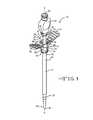
- FIG. 1illustrates a perspective view of an embodiment of an introducer assembly device of the present invention.
- FIG. 1Ashows a perspective view of the components comprising the introducer assembly shown in FIG. 1 .
- FIG. 2illustrates a perspective view of a prior art introducer housing subassembly.
- FIG. 3shows a side view of an embodiment of an introducer housing subassembly comprising a notch stress confining feature of the present invention.
- FIG. 3Aillustrates a magnified view of the embodiment of the notch stress confining feature shown in FIG. 3 .
- FIG. 4shows a side view of an introducer housing subassembly comprising an alternate embodiment of a stress confining feature of the present invention.
- FIG. 5shows a side view of an introducer housing subassembly comprising an alternate embodiment of a stress confining feature of the present invention.
- FIG. 6illustrates an embodiment of a retainer ring of the present invention.
- FIG. 7illustrates the embodiment of the retainer ring of FIG. 6 being positioned within the introducer assembly of the present invention.
- FIG. 7Ashows a magnified view of the retainer ring, shown in FIG. 6 , positioned within the introducer assembly.
- FIG. 8illustrates an embodiment of the housing subassembly comprising a break-away flap feature.
- FIGS. 1 and 1Aillustrate an embodiment of an introducer assembly 10 of the present invention.
- the introducer assembly 10comprises an elongated introducer sheath 12 connected to an introducer housing subassembly 14 .
- the sheath 12is an elongate member having an introducer sheath sidewall 16 extending along a longitudinal axis A-A from a sheath proximal portion 18 to a sheath distal end 20 .
- the thickness of the sidewall 16 including the proximal section 18 extending to the distal end 20is from about 0.001 inches to about 0.050 inches.
- a lumen or passage 22provides for open communication along the entire length of the sheath 12 and into the introducer housing subassembly 14 .
- This lumen 22allows for a medical device, such as a lead or catheter, to be advanced through the assembly 10 .
- the lumen 22preferably has a diameter from about 0.05 inches to about 0.50 inches.
- the introducer assembly 10 of the present inventioncomprises a dilator subassembly 24 .
- the dilator subassembly 24comprises an elongated dilator sheath 26 connected to a bulbous dilator head 28 .
- the dilator head 28comprises a dilator head through-bore 30 which extends longitudinally through the length of the dilator head 28 .
- the dilator sheath 26is an elongate member having a dilator sheath sidewall 32 extending along a longitudinal axis B-B from a dilator sheath proximal portion 34 to a dilator sheath distal end 36 .
- the thickness of the dilator sheath sidewall 32including the proximal section 34 extending to the distal end 36 , is from about 0.001 inches to about 0.050 inches.
- the diameter of the distal end 36 of the dilator sheath 26may be narrow than the diameter of the proximal end portion 34 of the dilator sheath 26 .
- the distal end 36 of the dilator sheath 26may comprise a pointed end 38 .
- the dilator sheath 26is designed such that it may be inserted within the introducer sheath lumen 22 and extends longitudinally along axis A-A. As shown, the dilator head 28 mates with the housing subassembly 14 .
- a proximal portion 40 of the dilator head 28comprises a helical ridge or thread 42 positioned along an exterior surface 44 of the dilator head 28 .
- the helical ridge 42is designed to threadingly engage within a corresponding groove 46 residing within an interior surface 48 of the housing subassembly 14 .
- the dilator head 28When the dilator 24 is positioned within the lumen 22 of the sheath 12 , the dilator head 28 is rotated to threadingly engage the helical ridge 42 within the groove 46 of the housing subassembly 14 forming a secure fit therebetween.
- the dilator 24may be removed from the sheath 12 by reversing the rotation of the dilator head 28 and removing the dilator from the sheath 12 of the introducer 10 .
- the housing subassembly 14comprises a housing body 50 having a housing base portion 52 that fluidly extends to an upper housing web portion 54 .
- a housing through-bore 56defining a housing sidewall 58 , extends longitudinally along axis A-A.
- a portion of the sheath proximal region 18is supported within the through-bore 56 of the housing subassembly 14 . More specifically, the portion of the sheath proximal region 18 is designed to be positioned within the through-bore opening 56 of the housing 50 , such that the opening of the lumen 22 and the housing through-bore 56 are aligned.
- the base portion 52 of the housing body 50circumferentially extends around an exterior surface 60 of the introducer sheath 12 forming a tight interference fit therebetween.
- the base portion 52 of the housing body 50may be molded over the proximal end portion 18 of the sheath 12 .
- the stress confining featurecomprises a notch 64 that extends from a proximal end 66 of the upper web portion 54 of the housing body 50 to a stress concentration area or point 68 ( FIGS. 3 to 5 ), distal of the proximal end 66 .
- the notch 64preferably extends through at least a portion of the thickness of the housing body sidewall 58 .
- the notch 64may extend through the entire thickness of the sidewall 58 of the web portion 54 of the housing 50 .
- a score-line 70extends distally from the stress concentration area or point 68 of the stress concentration notch 64 .
- the score-line 70preferably resides within a portion of an exterior surface 72 of the housing body 50 .
- the score-line 70extends from the stress concentration point 68 of the notch 64 to a distal end 74 of the base portion 52 of the housing 50 .
- the housing subassembly 14 of the introducer assembly 10 of the present inventionmay comprise a multitude of non-limiting notch geometries.
- wings 76 and 78which give the housing body 50 a butterfly appearance. More specifically, the opposing left and right wings 76 , 78 fluidly extend from an exterior surface 80 of the upper web portion 54 of the housing body 50 . These wings 76 , 78 are designed such that when a downward and counter rotated force is applied to them, a separation force is thereby applied to the stress concentration feature 62 or notch 64 of the housing body 50 . The notch 64 then focuses the separation force to the stress concentration point 68 were a housing separation crack is initiated. Upon the application of an additional opposed lateral pulling force, the initiated crack propagates along the score-line 70 thereby separating the housing subassembly 14 and introducer sheath 12 .
- an embodiment of a housing subassembly 82 of the prior artdoes not comprise such a stress confining feature or notch.
- the prior art housing 82comprises only the score-line 70 that extends longitudinally from its proximal portion to the distal portion of the housing 82 .
- the lack of such a stress confining feature 62 such as the present notch 64means that a relatively greater force is required to separate the prior art housing 82 to initiate subsequent splitting separation of the sheath 12 .
- FIGS. 3 , 3 A, 4 and 5illustrate preferred embodiments of introducer housing subassemblies. Specifically, FIGS. 3 , 3 A, 4 and 5 show preferred embodiments of various stress confining features 62 of the present invention.
- FIGS. 3 and 3Aillustrate an embodiment of an introducer housing subassembly 84 comprising a notch 86 having a rectangular cross-section. As shown, the notch 86 is formed by removing a portion of the thickness of the sidewall 58 of the upper web portion 54 of the housing 84 . More specifically, as shown in FIG. 3A , the notch 86 comprises a notch width 87 , a notch length 89 , and a notch depth.
- the notch width 87may range from about 0.01 inches to about 0.25 inches
- the notch length 89may range from about 0.01 inches to about 0.25 inches
- the notch depthmay also range from about 0.01 inches to about 0.25 inches.
- the width of the notch 86may be greater than the width of the prior art score-line 70 ( FIG. 2 ).
- the length of the notch 86may also range from about 5% to about 50% of the length of the upper web portion 54 of the hosing body 50 .
- the depth of the notch 86may be about equal to the thickness of the sidewall 58 of the housing 50 , particularly the sidewall thickness of the upper web portion 54 of the housing 50 .
- FIG. 4illustrates an alternate embodiment of an introducer housing subassembly 88 comprising a notch 90 having a “V” or wedge-like cross-section.
- this notch 90comprises a first notch sidewall 92 and a second notch sidewall 94 that converge at the stress concentration point 68 .
- each of the first and second sidewalls 92 , 94has a notch angle 96 that ranges from about 5° to about 90°.
- the notch angle 96is defined as the angle between longitudinal axis A-A and a surface 98 of the notch sidewall 92 , 94 .
- the first or second notch sidewalls 92 , 94may have a similar or different notch angle 96 .
- the notchalso comprises a notch depth that approximates the thickness of the sidewall 58 of the web portion 54 of the housing body 50 .
- FIG. 5illustrates yet another alternate embodiment of an introducer housing subassembly 100 comprising a notch 102 having a curved cross-section.
- the notch 102comprises a curved surface 104 that resides within a portion of the thickness of the sidewall 58 of the housing body 50 .
- the curved surface of the notchhas a notch radius of curvature that ranges from about 0.1 inches to about 0.25 inches.
- the notch 102comprises a notch depth 106 that penetrates through a portion of the length of the web portion 54 of the housing 50 . As shown, the notch depth extends from the proximal housing end 66 of the upper web portion 54 to a point distal of the proximal end 66 . In a preferred embodiment, the notch depth 106 may range from about 0.01 inches to about 0.25 inches. Alternatively, the notch depth 106 may range from about 5 percent to about 25 percent of the length of the web portion 54 . The notch also comprises a notch width that may span about the thickness of the sidewall of the upper web portion 54 .
- Table Ishown below, summarizes the mechanical test data of the introducer assembly of the prior art. As shown, the average measured forces required to separate the housing 82 , of various introducer diameters, i.e., French sizes, of the prior art design are detailed below in Table I. During the test, separation forces were measured and averaged for a total of 10 introducer samples per French size, sizes 7 French to 17 French in total.
- the French size scaleis commonly used in the medical device arts to denote the diameter of a lead or a catheter. A French size of 1 equates to a diameter of about 0.33 mm.
- Table IIshown below, summarizes the mechanical test data of the force required to separate the housing subassembly 100 of the present invention among various French sizes. More specially, separation forces were measured and averaged on a total of 10 introducer samples per French size, sizes 7 French to 17 French in total.
- the test samplescomprised the curved notch feature embodied in FIG. 5 .
- the overall average force required to separate the notched housing 100 of the introducer assembly 10 of the present inventionwas less than the average force required to separate the housing 82 of introducer assembly of the prior art.
- the test datatherefore, illustrates a direct reduction in the separation force of the introducer assembly 10 of the present invention comprising the notched housing 100 .
- the increased process capability index values (Cpk) resulting from the testing of the introducer design of the present inventionillustrate the increased repeatability of the force required to separate the test samples.
- Process capability indexis herein defined as a statistical measure of process control. The greater the Cpk value, the greater the repeatability and control the process, or in this case, the measured separation force values.
- Table IIIdetails the percent difference in the average measured forces required to separate the respective housing subassemblies. As shown, the average force required to separate the housing assembly 82 of the prior art design was greater for every diameter size. For example, the force required to separate a 10 French diameter prior art introducer assembly measured, on average, about 17.5 lb-force. In comparison, the average force required to separate the housing 100 of the introducer assembly 10 of the present invention comprising the curved notch 102 measured about 13.2 lb-force. This, as shown in Table III, corresponds to a reduction in separation force of about 24.4 percent. Therefore, as can be seen from the test data above, the force required to separate the notched introducer assembly of the present invention is not only less than the force required to separate the introducer assembly of the prior art but also exhibits greater consistency and repeatability.
- FIGS. 6 , 7 and 7 Aillustrate an embodiment of a retainer ring 108 .
- the retainer ring 108may be used with the introducer assembly 10 of the present invention as a means to prevent the possible flow of fluids such as a gas or liquid through the opening of the notch 64 .
- the ring 108is designed to be either placed adjacent to or inserted within the proximal end 66 of the housing subassembly 14 .
- the retainer ring 108comprises an annular retainer body 110 in which a retainer through-bore 112 extends. Extending from a perimeter sidewall 114 of the ring 108 is a tab 116 that is designed to be inserted within the notch 64 of the housing body 50 .
- At least two opposing tabs 116project from the perimeter sidewall 114 of the retainer ring 108 .
- the tab or tabs 116are dimensioned to fit within the opening of the notch 64 .
- the tab 116is of a rectangular cross-section however, the tab 116 may comprise a cross-sectional dimension such that the tab 116 fits within the various embodiments of the notches.
- the retainer ring 108maybe positioned over or within the through-bore opening of the proximal end 66 of the housing subassembly 14 .
- a clip 118 portion of the housing body 50may be used to hold the retainer ring 108 in place within or over the through-bore 56 of the proximal end 66 of the housing subassembly 14 .
- the clip 118is positioned within a recess 119 of the perimeter sidewall 114 of the retainer ring 108 ( FIG. 6 ).
- the clips 118are diametrically opposite to each other and preferably offset 45° from the tabs 116 .
- FIG. 8illustrates yet another alternate embodiment of a housing subassembly 120 of the present invention. Similar to the previous embodiments of the housing subassemblies, this embodiment comprises a housing body 122 having opposing left and right wings 76 , 78 that extend from the exterior surface 72 of the body 122 . Similar to the previous housing subassemblies of the present invention, the score-line 70 resides within a portion of the thickness of the exterior surface 72 extending from the upper web portion 54 to the distal base portion 52 of the housing 120 . The central throughbore 56 extends therethrough.
- this embodiment 120comprises a flap 124 that is designed to break away when a force is applied to the left and right wings 76 , 78 .
- the housing subassembly 120comprises a series of raised ridges 126 residing within the left and right wings 76 , 78 . These ridges 126 are designed to add strength and rigidity to the wings 76 , 78 .
- the flap 124is connected between the opposing left and right wings 76 , 78 of the housing subassembly 120 , such as by molding. More specifically, as shown in FIG. 8 , the flap 124 is positioned and connected between respective left and right sides 122 A, 122 B of the upper housing portion 54 . Each flap 124 resides within a corresponding notch 128 within the sidewall 58 of the housing upper portion 54 of the housing subassembly 120 .
- each flap 124may be composed of a rigid polymeric material that easily breaks under a mechanical stress.
- the flap 124may be composed of santoprene, silicone, polyether block amides and the like.
- the flap 124breaks off, of the left and right side 122 A, 122 B of the upper housing portion 54 , thereby exposing the notch 64 positioned within the sidewall 58 of the housing body 122 .
- the notch 128concentrates application of the separation force to the score-line 70 , thereby initiating a separation crack therebetween.
- the dilator 24is received inside the lumen 22 of the introducer sheath 12 .
- Thisallows for the introducer assembly to be introduced into the vasculature of a patient, for instance, over a guide wire (not shown).
- Thispositions the distal end 20 of the sheath 12 inside the vasculature while the proximal section 18 and the housing subassembly 14 remain outside the patient.
- the retainer ring 108may be positioned within the through-bore 56 of the housing subassembly 14 at its proximal end 66 to prevent blood and other body fluids from leaking out of the vasculature and outside air from getting in.
- the introducer assembly 10 of the present inventionis split apart for removal from the vasculature. This is done by holding the wings 76 , 78 between the thumb and fore finger and counter rotating them with respect to each other while slowly moving the wings further apart.
- the housing body 50is readily separated. This occurs at the score-line 70 that runs along the base portion 52 of the housing body 50 .
- the resulting halves of the housingbegin to exert a force on the proximal end 18 of the sheath 12 .
- These forcesare concentrated at the notch 64 , particularly at the stress concentration point 68 to initiate a tear at the proximal end of the score-line 70 .
- the force generated by further manipulation of the wings 76 , 78is concentrated at the lower extent or distal stress point/area 68 of each notch feature 64 . This concentrated force is sufficient to cause the material of the housing subassembly 14 to sever or tear apart from the sheath 12 .
- the housing subassembly 14 of the present inventionis preferably composed of an acrylic based polymeratial, such as polymethyl methacrylate.
- the housing subassembly 14may also be composed of ethyl acrylate, 2-chloroethyl vinyl ether, 2-ethylhexyl acrylate, hydroxyethyl methacrylate, butyl acrylate, butyl methacrylate and the like.
- the sheath 12 of the present inventionpreferably comprises polytetrafluoroethylene (PTFE). While PTFE is the most preferred material for the housing 14 , other fluoropolymeric materials may also be used. These include polyhexafluoropropylene, tetrafluoroethylene-hexafluoropropylene copolymers, tetrafluoroethylene-perfluoroalkyl vinyl ether copolymers, polytrifluoroethylene, ethylene-tetrafluoroethylene copolymers, fluoroethylene-hydrocarbon vinyl ether copolymers, polychlorotrifluoroethylene, ethylene-chlorotrifluoroethylene copolymers, polyvinyl fluoride, polyvinylidene fluoride, vinylidene fluoride-hexafluoropropylene copolymers, fluorinated (meth)acrylate resins, 2-fluoroacrylate resins, fluorinated epoxy resins, fluorinated epoxy (meth
- the present inventionthus provides the upper web portion 54 of the introducer 10 with structures that concentrate the tearing forces created by moving the wings 76 , 78 apart to stress confining features 62 located diametrically opposite each other in the housing sidewall 58 .
- the present inventionis not meant to be limited to the notch embodiments discussed and illustrated. Any structure located at the upper web portion 54 of the housing body 50 that serves to concentrate the tearing forces to a confined area is contemplated by the scope of the present invention.
- the present inventionhas described several structures suitable as stress confining structures for concentrating the separating forces exerted at the upper web portion 54 of the housing body 50 by a pulling manipulation of the wings 76 , 78 .
- the total forces imparted to the wings 76 , 78are concentrated at either diametrically opposed surfaces along the proximal end 66 of the upper web portion 54 .
- PTFEas the preferred material for the sheath 12 , once a tear begins it propagates the entire length of the sheath, no matter how long, in an extremely smooth manner that provides the physician with a very desirable tactile feel.
- an introducer assemblycomprising a housing supported on the proximal end of a sheath having a novel structure for removal from the venous system of a patient.
Landscapes
- Health & Medical Sciences (AREA)
- Life Sciences & Earth Sciences (AREA)
- Veterinary Medicine (AREA)
- Public Health (AREA)
- Engineering & Computer Science (AREA)
- General Health & Medical Sciences (AREA)
- Biomedical Technology (AREA)
- Heart & Thoracic Surgery (AREA)
- Animal Behavior & Ethology (AREA)
- Hematology (AREA)
- Anesthesiology (AREA)
- Pulmonology (AREA)
- Biophysics (AREA)
- Surgery (AREA)
- Pathology (AREA)
- Nuclear Medicine, Radiotherapy & Molecular Imaging (AREA)
- Medical Informatics (AREA)
- Molecular Biology (AREA)
- Media Introduction/Drainage Providing Device (AREA)
Abstract
Description
| TABLE I | ||
| Dia. | ||
| 7 | 8 | 9 | 10 | 11 | 12 | 13 | 14 | 15 | 16 | 17 | ||
| Fr | Fr | Fr | Fr | Fr | Fr | Fr | Fr | Fr | Fr | Fr | ||
| Avg. | 14.8 | 18.0 | 17.2 | 17.5 | 15.1 | 14.2 | 16.2 | 17.6 | 17.8 | 19.0 | 16.6 |
| Force | |||||||||||
| (lbs-f) | |||||||||||
| Std. | 0.5 | 0.2 | 0.3 | 0.4 | 0.4 | 0.3 | 1.5 | 0.9 | 0.4 | 0.9 | 0.5 |
| Dev. | |||||||||||
| Cpk | 3.6 | 4.6 | 2.8 | 1.9 | 4.7 | 5.9 | 0.8 | 0.9 | 1.7 | 0.4 | 2.5 |
| TABLE II | ||
| Dia. | ||
| 7 | 8 | 9 | 10 | 11 | 12 | 13 | 14 | 15 | 16 | 17 | ||
| Fr | Fr | Fr | Fr | Fr | Fr | Fr | Fr | Fr | Fr | Fr | ||
| Avg. | 11.4 | 13.6 | 13.6 | 13.2 | 10.6 | 9.8 | 11.4 | 13.2 | 14.0 | 14.9 | 12.7 |
| Force | |||||||||||
| (lbs-f) | |||||||||||
| Std. | 0.4 | 0.4 | 0.3 | 0.3 | 0.4 | 0.2 | 0.4 | 0.6 | 0.8 | 0.6 | 0.6 |
| Dev. | |||||||||||
| Cpk | 6.6 | 5.0 | 6.2 | 9.0 | 7.2 | 16.4 | 7.5 | 4.0 | 2.4 | 2.9 | 4.3 |
| TABLE III | ||
| Dia. | ||
| 7 | 8 | 9 | 10 | 11 | 12 | 13 | 14 | 15 | 16 | 17 | ||
| Fr | Fr | Fr | Fr | Fr | Fr | Fr | Fr | Fr | Fr | Fr | ||
| Percent | 22.5 | 24.2 | 20.6 | 24.4 | 29.9 | 30.8 | 29.7 | 25.1 | 21.1 | 21.5 | 23.3 |
| Diff. | |||||||||||
Claims (20)
Priority Applications (2)
| Application Number | Priority Date | Filing Date | Title |
|---|---|---|---|
| US13/555,470US8753313B2 (en) | 2011-07-22 | 2012-07-23 | Introducer handle notch design/concept |
| US14/307,054US9517323B2 (en) | 2011-07-22 | 2014-06-17 | Introducer handle notch design/concept |
Applications Claiming Priority (2)
| Application Number | Priority Date | Filing Date | Title |
|---|---|---|---|
| US201161510510P | 2011-07-22 | 2011-07-22 | |
| US13/555,470US8753313B2 (en) | 2011-07-22 | 2012-07-23 | Introducer handle notch design/concept |
Related Child Applications (1)
| Application Number | Title | Priority Date | Filing Date |
|---|---|---|---|
| US14/307,054ContinuationUS9517323B2 (en) | 2011-07-22 | 2014-06-17 | Introducer handle notch design/concept |
Publications (2)
| Publication Number | Publication Date |
|---|---|
| US20140025003A1 US20140025003A1 (en) | 2014-01-23 |
| US8753313B2true US8753313B2 (en) | 2014-06-17 |
Family
ID=49947155
Family Applications (2)
| Application Number | Title | Priority Date | Filing Date |
|---|---|---|---|
| US13/555,470ActiveUS8753313B2 (en) | 2011-07-22 | 2012-07-23 | Introducer handle notch design/concept |
| US14/307,054Active2032-07-31US9517323B2 (en) | 2011-07-22 | 2014-06-17 | Introducer handle notch design/concept |
Family Applications After (1)
| Application Number | Title | Priority Date | Filing Date |
|---|---|---|---|
| US14/307,054Active2032-07-31US9517323B2 (en) | 2011-07-22 | 2014-06-17 | Introducer handle notch design/concept |
Country Status (1)
| Country | Link |
|---|---|
| US (2) | US8753313B2 (en) |
Cited By (9)
| Publication number | Priority date | Publication date | Assignee | Title |
|---|---|---|---|---|
| US20140296788A1 (en)* | 2011-07-22 | 2014-10-02 | Greatbatch Ltd. | Introducer handle notch design/concept |
| USD804663S1 (en)* | 2016-09-08 | 2017-12-05 | Merit Medical Systems, Inc. | Introducer hub |
| USD870271S1 (en)* | 2017-10-10 | 2019-12-17 | Synaptive Medical (Barbados) Inc. | Shunt stylet |
| US10898690B2 (en) | 2016-03-22 | 2021-01-26 | The United States Of America As Represented By The Secretary Of The Air Force | Vascular access disassembling needle device and method |
| US11172959B2 (en) | 2018-05-02 | 2021-11-16 | Boston Scientific Neuromodulation Corporation | Long, flexible sheath and lead blank and systems and methods of making and using |
| US11654270B2 (en) | 2021-09-28 | 2023-05-23 | Biolinq Incorporated | Microneedle enclosure and applicator device for microneedle array based continuous analyte monitoring device |
| US11813418B2 (en) | 2019-08-22 | 2023-11-14 | Becton, Dickinson And Company | Echogenic balloon dilation catheter and balloon thereof |
| US12109382B2 (en) | 2019-08-23 | 2024-10-08 | Becton, Dickinson And Company | Device set designed for PCNL surgery |
| US12178660B2 (en) | 2019-08-22 | 2024-12-31 | Becton, Dickinson And Company | Echogenicity quantitative test system for an echogenic medical device |
Families Citing this family (9)
| Publication number | Priority date | Publication date | Assignee | Title |
|---|---|---|---|---|
| US20150231369A1 (en)* | 2014-02-20 | 2015-08-20 | Boston Scientific Scimed, Inc. | Peelable sheath |
| ES2764218T3 (en) | 2015-01-07 | 2020-06-02 | Abiomed Europe Gmbh | Introductory cover |
| WO2017147103A1 (en) | 2016-02-22 | 2017-08-31 | Abiomed, Inc. | Introducer sheath having a multi-layer hub |
| JP6776025B2 (en)* | 2016-06-30 | 2020-10-28 | テルモ株式会社 | Introducer sheath and introducer |
| AU2017373953B2 (en) | 2016-12-08 | 2023-05-11 | Abiomed, Inc. | Overmold technique for peel-away introducer design |
| ES2991910T3 (en) | 2018-05-16 | 2024-12-05 | Abiomed Inc | Removable cover set |
| USD929582S1 (en)* | 2019-02-07 | 2021-08-31 | Caldera Medical, Inc. | Introducer handle for single incision sling implantation |
| USD929583S1 (en)* | 2019-02-07 | 2021-08-31 | Caldera Medical, Inc. | Introducer button for single incision sling implantation |
| US11252874B2 (en)* | 2020-04-24 | 2022-02-22 | Seoul Viosys Co., Ltd. | Light source module for plant cultivation |
Citations (25)
| Publication number | Priority date | Publication date | Assignee | Title |
|---|---|---|---|---|
| USRE31855E (en) | 1978-12-01 | 1985-03-26 | Cook, Inc. | Tear apart cannula |
| US4596559A (en) | 1984-11-02 | 1986-06-24 | Fleischhacker John J | Break-away handle for a catheter introducer set |
| US4772266A (en) | 1987-05-04 | 1988-09-20 | Catheter Technology Corp. | Catheter dilator/sheath assembly and method |
| USD318733S (en) | 1988-03-24 | 1991-07-30 | Quinton Instrument Company | Pull-apart sheath introducer for percutaneous catheter introduction |
| US5125904A (en)* | 1991-07-09 | 1992-06-30 | Lee Hongpyo H | Splittable hemostatic valve and sheath and the method for using the same |
| US5167634A (en)* | 1991-08-22 | 1992-12-01 | Datascope Investment Corp. | Peelable sheath with hub connector |
| US5250033A (en) | 1992-10-28 | 1993-10-05 | Interventional Thermodynamics, Inc. | Peel-away introducer sheath having proximal fitting |
| US5312355A (en)* | 1991-07-09 | 1994-05-17 | H L Medical Inventions, Inc. | Splittable hemostatic valve and sheath and the method for using the same |
| US5397311A (en)* | 1992-09-09 | 1995-03-14 | Menlo Care, Inc. | Bloodless splittable introducer |
| US5549576A (en) | 1993-05-07 | 1996-08-27 | C. R. Bard, Inc. | Vascular introducer valve with proximal self-lubrication |
| US5879333A (en)* | 1995-04-24 | 1999-03-09 | Microcatheters Pty Ltd | Catheter with body locking into cannula hub |
| US5951518A (en) | 1997-10-31 | 1999-09-14 | Teleflex, Incorporated | Introducing device with flared sheath end |
| USD450839S1 (en) | 2000-02-07 | 2001-11-20 | Larry G. Junker | Handle for introducer sheath |
| US20020128603A1 (en)* | 2000-09-08 | 2002-09-12 | Pall Corporation | Cannula assembly |
| US6454744B1 (en) | 1999-12-23 | 2002-09-24 | Tfx Medical, Inc. | Peelable PTFE sheaths and methods for manufacture of same |
| US6692464B2 (en)* | 2002-02-28 | 2004-02-17 | Cook, Incorporated | T-fitting for splittable sheath |
| US20050010238A1 (en)* | 2003-07-08 | 2005-01-13 | Potter Daniel J. | Detachable hemostasis valve and splittable sheath assembly |
| US20050049628A1 (en)* | 2002-08-29 | 2005-03-03 | Medical Components, Inc. | Releasably locking dilator and sheath assembly |
| US6878134B2 (en)* | 2002-11-04 | 2005-04-12 | Aragon Medical | Safety needle assembly with locking retraction |
| US20060106416A1 (en)* | 2004-10-29 | 2006-05-18 | Douglas Raymond | Expandable ports and methods for minimally invasive surgery |
| USD532513S1 (en) | 2004-03-19 | 2006-11-21 | Galt Medical Corporation | Handle for an introducer sheath |
| US20090192463A1 (en)* | 2008-01-29 | 2009-07-30 | Medical Components, Inc | Introducer Sheath Assembly with Hub and Method of Joining a Hub to a Sheath Tube |
| US20100100044A1 (en) | 2008-10-22 | 2010-04-22 | Greatbatch Medical | Splittable Valved Introducer Apparatus |
| US20110264047A1 (en) | 2004-08-05 | 2011-10-27 | Greatbatch Ltd. | Valved Introducer Assembly and Method Therefor |
| US8109908B1 (en)* | 2008-01-22 | 2012-02-07 | Greatbatch Ltd. | Biodegradable shroud for a dilator/sheath assembly |
Family Cites Families (1)
| Publication number | Priority date | Publication date | Assignee | Title |
|---|---|---|---|---|
| US8753313B2 (en)* | 2011-07-22 | 2014-06-17 | Greatbatch Ltd. | Introducer handle notch design/concept |
- 2012
- 2012-07-23USUS13/555,470patent/US8753313B2/enactiveActive
- 2014
- 2014-06-17USUS14/307,054patent/US9517323B2/enactiveActive
Patent Citations (27)
| Publication number | Priority date | Publication date | Assignee | Title |
|---|---|---|---|---|
| USRE31855E (en) | 1978-12-01 | 1985-03-26 | Cook, Inc. | Tear apart cannula |
| USRE31855F1 (en) | 1978-12-01 | 1986-08-19 | Tear apart cannula | |
| US4596559A (en) | 1984-11-02 | 1986-06-24 | Fleischhacker John J | Break-away handle for a catheter introducer set |
| US4772266A (en) | 1987-05-04 | 1988-09-20 | Catheter Technology Corp. | Catheter dilator/sheath assembly and method |
| USD318733S (en) | 1988-03-24 | 1991-07-30 | Quinton Instrument Company | Pull-apart sheath introducer for percutaneous catheter introduction |
| US5125904A (en)* | 1991-07-09 | 1992-06-30 | Lee Hongpyo H | Splittable hemostatic valve and sheath and the method for using the same |
| US5312355A (en)* | 1991-07-09 | 1994-05-17 | H L Medical Inventions, Inc. | Splittable hemostatic valve and sheath and the method for using the same |
| US5125904B1 (en)* | 1991-07-09 | 1996-11-19 | Hl Medical Inventions Inc | Splittable hemostatic valve sheath and the method for using the same |
| US5167634A (en)* | 1991-08-22 | 1992-12-01 | Datascope Investment Corp. | Peelable sheath with hub connector |
| US5397311A (en)* | 1992-09-09 | 1995-03-14 | Menlo Care, Inc. | Bloodless splittable introducer |
| US5250033A (en) | 1992-10-28 | 1993-10-05 | Interventional Thermodynamics, Inc. | Peel-away introducer sheath having proximal fitting |
| US5549576A (en) | 1993-05-07 | 1996-08-27 | C. R. Bard, Inc. | Vascular introducer valve with proximal self-lubrication |
| US5879333A (en)* | 1995-04-24 | 1999-03-09 | Microcatheters Pty Ltd | Catheter with body locking into cannula hub |
| US5951518A (en) | 1997-10-31 | 1999-09-14 | Teleflex, Incorporated | Introducing device with flared sheath end |
| US6454744B1 (en) | 1999-12-23 | 2002-09-24 | Tfx Medical, Inc. | Peelable PTFE sheaths and methods for manufacture of same |
| USD450839S1 (en) | 2000-02-07 | 2001-11-20 | Larry G. Junker | Handle for introducer sheath |
| US20020128603A1 (en)* | 2000-09-08 | 2002-09-12 | Pall Corporation | Cannula assembly |
| US6692464B2 (en)* | 2002-02-28 | 2004-02-17 | Cook, Incorporated | T-fitting for splittable sheath |
| US20050049628A1 (en)* | 2002-08-29 | 2005-03-03 | Medical Components, Inc. | Releasably locking dilator and sheath assembly |
| US6878134B2 (en)* | 2002-11-04 | 2005-04-12 | Aragon Medical | Safety needle assembly with locking retraction |
| US20050010238A1 (en)* | 2003-07-08 | 2005-01-13 | Potter Daniel J. | Detachable hemostasis valve and splittable sheath assembly |
| USD532513S1 (en) | 2004-03-19 | 2006-11-21 | Galt Medical Corporation | Handle for an introducer sheath |
| US20110264047A1 (en) | 2004-08-05 | 2011-10-27 | Greatbatch Ltd. | Valved Introducer Assembly and Method Therefor |
| US20060106416A1 (en)* | 2004-10-29 | 2006-05-18 | Douglas Raymond | Expandable ports and methods for minimally invasive surgery |
| US8109908B1 (en)* | 2008-01-22 | 2012-02-07 | Greatbatch Ltd. | Biodegradable shroud for a dilator/sheath assembly |
| US20090192463A1 (en)* | 2008-01-29 | 2009-07-30 | Medical Components, Inc | Introducer Sheath Assembly with Hub and Method of Joining a Hub to a Sheath Tube |
| US20100100044A1 (en) | 2008-10-22 | 2010-04-22 | Greatbatch Medical | Splittable Valved Introducer Apparatus |
Cited By (10)
| Publication number | Priority date | Publication date | Assignee | Title |
|---|---|---|---|---|
| US20140296788A1 (en)* | 2011-07-22 | 2014-10-02 | Greatbatch Ltd. | Introducer handle notch design/concept |
| US9517323B2 (en)* | 2011-07-22 | 2016-12-13 | Greatbatch Ltd. | Introducer handle notch design/concept |
| US10898690B2 (en) | 2016-03-22 | 2021-01-26 | The United States Of America As Represented By The Secretary Of The Air Force | Vascular access disassembling needle device and method |
| USD804663S1 (en)* | 2016-09-08 | 2017-12-05 | Merit Medical Systems, Inc. | Introducer hub |
| USD870271S1 (en)* | 2017-10-10 | 2019-12-17 | Synaptive Medical (Barbados) Inc. | Shunt stylet |
| US11172959B2 (en) | 2018-05-02 | 2021-11-16 | Boston Scientific Neuromodulation Corporation | Long, flexible sheath and lead blank and systems and methods of making and using |
| US11813418B2 (en) | 2019-08-22 | 2023-11-14 | Becton, Dickinson And Company | Echogenic balloon dilation catheter and balloon thereof |
| US12178660B2 (en) | 2019-08-22 | 2024-12-31 | Becton, Dickinson And Company | Echogenicity quantitative test system for an echogenic medical device |
| US12109382B2 (en) | 2019-08-23 | 2024-10-08 | Becton, Dickinson And Company | Device set designed for PCNL surgery |
| US11654270B2 (en) | 2021-09-28 | 2023-05-23 | Biolinq Incorporated | Microneedle enclosure and applicator device for microneedle array based continuous analyte monitoring device |
Also Published As
| Publication number | Publication date |
|---|---|
| US9517323B2 (en) | 2016-12-13 |
| US20140025003A1 (en) | 2014-01-23 |
| US20140296788A1 (en) | 2014-10-02 |
Similar Documents
| Publication | Publication Date | Title |
|---|---|---|
| US8753313B2 (en) | Introducer handle notch design/concept | |
| US11697000B2 (en) | Access device with valve | |
| US7993305B2 (en) | Splittable valved introducer apparatus | |
| US10307182B2 (en) | Valved sheath introducer for venous cannulation | |
| US10682157B2 (en) | Vascular access device | |
| US20040267202A1 (en) | Tearable hemostasis valve and splittable sheath | |
| JP4448514B2 (en) | Removable hemostatic valve-split sheath assembly | |
| US8251923B2 (en) | Device for introducing a catheter guide wire into a vessel | |
| US7377909B2 (en) | Connection assembly for use with splittable sheath | |
| EP1977783A1 (en) | Introducer assembly and method therefor | |
| US20140025036A1 (en) | Access device | |
| CA3071006A1 (en) | Needle and catheter insertion device | |
| US20080082056A1 (en) | Introducer assembly and method therefor | |
| KR102709635B1 (en) | Method and device for introducing a needle for catheter placement | |
| CA2605897A1 (en) | Low profile introducer apparatus | |
| CN219783530U (en) | Catheter adapter and vascular access assembly |
Legal Events
| Date | Code | Title | Description |
|---|---|---|---|
| AS | Assignment | Owner name:GREATBATCH LTD., NEW YORK Free format text:ASSIGNMENT OF ASSIGNORS INTEREST;ASSIGNORS:KIMMEL, SCOTT;KAMPA, NICHOLAS;NELSON, MARK;AND OTHERS;REEL/FRAME:028613/0294 Effective date:20120718 | |
| STCF | Information on status: patent grant | Free format text:PATENTED CASE | |
| AS | Assignment | Owner name:MANUFACTURERS AND TRADERS TRUST COMPANY, NEW YORK Free format text:SECURITY INTEREST;ASSIGNORS:GREATBATCH, INC.;GREATBATCH LTD.;ELECTROCHEM SOLUTIONS, INC.;AND OTHERS;REEL/FRAME:036980/0482 Effective date:20151027 | |
| MAFP | Maintenance fee payment | Free format text:PAYMENT OF MAINTENANCE FEE, 4TH YEAR, LARGE ENTITY (ORIGINAL EVENT CODE: M1551) Year of fee payment:4 | |
| AS | Assignment | Owner name:WELLS FARGO BANK, NATIONAL ASSOCIATION, AS ADMINISTRATIVE AGENT, VIRGINIA Free format text:SECURITY INTEREST;ASSIGNORS:GREATBATCH LTD.;ELECTROCHEM SOLUTIONS, INC.;LAKE REGION MEDICAL, INC.;AND OTHERS;REEL/FRAME:057468/0056 Effective date:20210902 | |
| MAFP | Maintenance fee payment | Free format text:PAYMENT OF MAINTENANCE FEE, 8TH YEAR, LARGE ENTITY (ORIGINAL EVENT CODE: M1552); ENTITY STATUS OF PATENT OWNER: LARGE ENTITY Year of fee payment:8 | |
| AS | Assignment | Owner name:MICRO POWER ELECTRONICS, INC., NEW YORK Free format text:RELEASE BY SECURED PARTY;ASSIGNOR:MANUFACTURERS AND TRADERS TRUST COMPANY (AS ADMINISTRATIVE AGENT);REEL/FRAME:060938/0069 Effective date:20210903 Owner name:PRECIMED INC., NEW YORK Free format text:RELEASE BY SECURED PARTY;ASSIGNOR:MANUFACTURERS AND TRADERS TRUST COMPANY (AS ADMINISTRATIVE AGENT);REEL/FRAME:060938/0069 Effective date:20210903 Owner name:GREATBATCH-GLOBE TOOL, INC., NEW YORK Free format text:RELEASE BY SECURED PARTY;ASSIGNOR:MANUFACTURERS AND TRADERS TRUST COMPANY (AS ADMINISTRATIVE AGENT);REEL/FRAME:060938/0069 Effective date:20210903 Owner name:NEURONEXUS TECHNOLOGIES, INC., NEW YORK Free format text:RELEASE BY SECURED PARTY;ASSIGNOR:MANUFACTURERS AND TRADERS TRUST COMPANY (AS ADMINISTRATIVE AGENT);REEL/FRAME:060938/0069 Effective date:20210903 Owner name:ELECTROCHEM SOLUTIONS, INC., NEW YORK Free format text:RELEASE BY SECURED PARTY;ASSIGNOR:MANUFACTURERS AND TRADERS TRUST COMPANY (AS ADMINISTRATIVE AGENT);REEL/FRAME:060938/0069 Effective date:20210903 Owner name:GREATBATCH LTD., NEW YORK Free format text:RELEASE BY SECURED PARTY;ASSIGNOR:MANUFACTURERS AND TRADERS TRUST COMPANY (AS ADMINISTRATIVE AGENT);REEL/FRAME:060938/0069 Effective date:20210903 Owner name:GREATBATCH, INC., NEW YORK Free format text:RELEASE BY SECURED PARTY;ASSIGNOR:MANUFACTURERS AND TRADERS TRUST COMPANY (AS ADMINISTRATIVE AGENT);REEL/FRAME:060938/0069 Effective date:20210903 | |
| AS | Assignment | Owner name:MICRO POWER ELECTRONICS, INC., NEW YORK Free format text:RELEASE BY SECURED PARTY;ASSIGNOR:MANUFACTURERS AND TRADERS TRUST COMPANY (AS ADMINISTRATIVE AGENT);REEL/FRAME:061659/0858 Effective date:20210903 Owner name:PRECIMED INC., NEW YORK Free format text:RELEASE BY SECURED PARTY;ASSIGNOR:MANUFACTURERS AND TRADERS TRUST COMPANY (AS ADMINISTRATIVE AGENT);REEL/FRAME:061659/0858 Effective date:20210903 Owner name:GREATBATCH-GLOBE TOOL, INC., NEW YORK Free format text:RELEASE BY SECURED PARTY;ASSIGNOR:MANUFACTURERS AND TRADERS TRUST COMPANY (AS ADMINISTRATIVE AGENT);REEL/FRAME:061659/0858 Effective date:20210903 Owner name:NEURONEXUS TECHNOLOGIES, INC., NEW YORK Free format text:RELEASE BY SECURED PARTY;ASSIGNOR:MANUFACTURERS AND TRADERS TRUST COMPANY (AS ADMINISTRATIVE AGENT);REEL/FRAME:061659/0858 Effective date:20210903 Owner name:ELECTROCHEM SOLUTIONS, INC., NEW YORK Free format text:RELEASE BY SECURED PARTY;ASSIGNOR:MANUFACTURERS AND TRADERS TRUST COMPANY (AS ADMINISTRATIVE AGENT);REEL/FRAME:061659/0858 Effective date:20210903 Owner name:GREATBATCH LTD., NEW YORK Free format text:RELEASE BY SECURED PARTY;ASSIGNOR:MANUFACTURERS AND TRADERS TRUST COMPANY (AS ADMINISTRATIVE AGENT);REEL/FRAME:061659/0858 Effective date:20210903 Owner name:GREATBATCH, INC., NEW YORK Free format text:RELEASE BY SECURED PARTY;ASSIGNOR:MANUFACTURERS AND TRADERS TRUST COMPANY (AS ADMINISTRATIVE AGENT);REEL/FRAME:061659/0858 Effective date:20210903 |