US8753292B2 - Method for locating a catheter tip using audio detection - Google Patents
Method for locating a catheter tip using audio detectionDownload PDFInfo
- Publication number
- US8753292B2 US8753292B2US13/251,686US201113251686AUS8753292B2US 8753292 B2US8753292 B2US 8753292B2US 201113251686 AUS201113251686 AUS 201113251686AUS 8753292 B2US8753292 B2US 8753292B2
- Authority
- US
- United States
- Prior art keywords
- audio
- catheter tip
- audio signal
- catheter
- sensor
- Prior art date
- Legal status (The legal status is an assumption and is not a legal conclusion. Google has not performed a legal analysis and makes no representation as to the accuracy of the status listed.)
- Expired - Fee Related, expires
Links
Images


Classifications
- A—HUMAN NECESSITIES
- A61—MEDICAL OR VETERINARY SCIENCE; HYGIENE
- A61B—DIAGNOSIS; SURGERY; IDENTIFICATION
- A61B8/00—Diagnosis using ultrasonic, sonic or infrasonic waves
- A61B8/08—Clinical applications
- A61B8/0833—Clinical applications involving detecting or locating foreign bodies or organic structures
- A61B8/0841—Clinical applications involving detecting or locating foreign bodies or organic structures for locating instruments
- A—HUMAN NECESSITIES
- A61—MEDICAL OR VETERINARY SCIENCE; HYGIENE
- A61B—DIAGNOSIS; SURGERY; IDENTIFICATION
- A61B5/00—Measuring for diagnostic purposes; Identification of persons
- A61B5/06—Devices, other than using radiation, for detecting or locating foreign bodies ; Determining position of diagnostic devices within or on the body of the patient
- A61B5/061—Determining position of a probe within the body employing means separate from the probe, e.g. sensing internal probe position employing impedance electrodes on the surface of the body
- A—HUMAN NECESSITIES
- A61—MEDICAL OR VETERINARY SCIENCE; HYGIENE
- A61B—DIAGNOSIS; SURGERY; IDENTIFICATION
- A61B5/00—Measuring for diagnostic purposes; Identification of persons
- A61B5/02—Detecting, measuring or recording for evaluating the cardiovascular system, e.g. pulse, heart rate, blood pressure or blood flow
- A61B5/0205—Simultaneously evaluating both cardiovascular conditions and different types of body conditions, e.g. heart and respiratory condition
- A—HUMAN NECESSITIES
- A61—MEDICAL OR VETERINARY SCIENCE; HYGIENE
- A61B—DIAGNOSIS; SURGERY; IDENTIFICATION
- A61B5/00—Measuring for diagnostic purposes; Identification of persons
- A61B5/24—Detecting, measuring or recording bioelectric or biomagnetic signals of the body or parts thereof
- A61B5/316—Modalities, i.e. specific diagnostic methods
- A61B5/318—Heart-related electrical modalities, e.g. electrocardiography [ECG]
- A—HUMAN NECESSITIES
- A61—MEDICAL OR VETERINARY SCIENCE; HYGIENE
- A61B—DIAGNOSIS; SURGERY; IDENTIFICATION
- A61B7/00—Instruments for auscultation
- A61B7/02—Stethoscopes
- A61B7/04—Electric stethoscopes
- A—HUMAN NECESSITIES
- A61—MEDICAL OR VETERINARY SCIENCE; HYGIENE
- A61M—DEVICES FOR INTRODUCING MEDIA INTO, OR ONTO, THE BODY; DEVICES FOR TRANSDUCING BODY MEDIA OR FOR TAKING MEDIA FROM THE BODY; DEVICES FOR PRODUCING OR ENDING SLEEP OR STUPOR
- A61M25/00—Catheters; Hollow probes
- A61M25/01—Introducing, guiding, advancing, emplacing or holding catheters
- A61M25/0105—Steering means as part of the catheter or advancing means; Markers for positioning
- A61M25/0108—Steering means as part of the catheter or advancing means; Markers for positioning using radio-opaque or ultrasound markers
- A—HUMAN NECESSITIES
- A61—MEDICAL OR VETERINARY SCIENCE; HYGIENE
- A61B—DIAGNOSIS; SURGERY; IDENTIFICATION
- A61B34/00—Computer-aided surgery; Manipulators or robots specially adapted for use in surgery
- A61B34/20—Surgical navigation systems; Devices for tracking or guiding surgical instruments, e.g. for frameless stereotaxis
- A61B2034/2046—Tracking techniques
- A61B2034/2063—Acoustic tracking systems, e.g. using ultrasound
- A—HUMAN NECESSITIES
- A61—MEDICAL OR VETERINARY SCIENCE; HYGIENE
- A61B—DIAGNOSIS; SURGERY; IDENTIFICATION
- A61B2562/00—Details of sensors; Constructional details of sensor housings or probes; Accessories for sensors
- A61B2562/02—Details of sensors specially adapted for in-vivo measurements
- A61B2562/0204—Acoustic sensors
- A—HUMAN NECESSITIES
- A61—MEDICAL OR VETERINARY SCIENCE; HYGIENE
- A61M—DEVICES FOR INTRODUCING MEDIA INTO, OR ONTO, THE BODY; DEVICES FOR TRANSDUCING BODY MEDIA OR FOR TAKING MEDIA FROM THE BODY; DEVICES FOR PRODUCING OR ENDING SLEEP OR STUPOR
- A61M25/00—Catheters; Hollow probes
- A61M25/01—Introducing, guiding, advancing, emplacing or holding catheters
- A61M25/0105—Steering means as part of the catheter or advancing means; Markers for positioning
- A61M2025/0166—Sensors, electrodes or the like for guiding the catheter to a target zone, e.g. image guided or magnetically guided
- A—HUMAN NECESSITIES
- A61—MEDICAL OR VETERINARY SCIENCE; HYGIENE
- A61M—DEVICES FOR INTRODUCING MEDIA INTO, OR ONTO, THE BODY; DEVICES FOR TRANSDUCING BODY MEDIA OR FOR TAKING MEDIA FROM THE BODY; DEVICES FOR PRODUCING OR ENDING SLEEP OR STUPOR
- A61M2205/00—General characteristics of the apparatus
- A61M2205/02—General characteristics of the apparatus characterised by a particular materials
- A61M2205/0272—Electro-active or magneto-active materials
- A61M2205/0294—Piezoelectric materials
Definitions
- the present inventionrelates generally to a method for locating a catheter tip within a human body. More specifically, the invention relates to a method for locating a catheter tip by detecting audio signals emitted from the catheter tip, processing the detected audio signals, and verifying that the catheter tip is at the target location.
- cathetersfor gaining prolonged access to an area within the body. Once the catheter tip is positioned at the target location, treatments such as antibiotics; chemotherapy, pain medicine, and nutrition can be administered. However, if the catheter tip is improperly positioned during insertion, or if the catheter tip migrates out of position after insertion, various risks arise, including a fluid infusion that causes pain or injury to the patient, complications due to increased thrombosis rates, delays in therapy, catheter malfunction and additional costs.
- peripherally inserted central cathetersare commonly inserted into a brachial, cephalic or basilic vein in the arm and advanced through the venous system towards the superior vena cava.
- Current medical standardsrecommended that the distal tip of the catheter terminate in the lower 1 ⁇ 3 of the superior vena cava, close to the junction of the superior vena cava and the right atrium.
- the PICC line tipmay be inadvertently positioned in a non-target area, such as the internal jugular or subclavian vein. Further, even if a PICC is property inserted, the catheter tip could later shift out of position if for example the patient coughs violently, moves a lot, or experiences severe vomiting. Therefore, verifying that the catheter tip is in the correct location is essential for safe operation of the catheter.
- Catheter tip location techniqueshave improved the ability of medical professionals to verify the location of the catheter tip.
- One techniqueuses fluoroscopy to confirm tip location. Fluoroscopy provides the operator with real-time images of the patient's anatomy using a fluoroscope.
- Another techniqueuses electromagnetic detection and a stylet having an electromagnetic sensor placed inside the lumen of the catheter tip. Electromagnetic systems use an external device positioned directly over the internal target area for generating a magnetic field outside of the body. The electromagnetic sensor on the stylet is then inserted into the body through the catheter lumen and measures when the magnetic flux is at its greatest. A monitor indicates to the user when the electromagnetic sensor on the stylet is centered underneath the external device.
- the external devicesenses the electromagnetic field, and an element at the tip of the stylet generates the electromagnetic field.
- Another techniqueuses ultrasound for guidance and determining catheter tip location.
- Electrocardiogram technologyis also used determine catheter tip location by measuring the change of the P wave as the catheter progresses down the superior vena cava.
- Fluoroscopyrequires a facility with fluoroscopy machine, and poses x-ray risks for both the patient and the operator. Further, interpreting the image in fluoroscopy and ultrasound can be difficult, and requires special training. Electromagnetic detection requires a stylet having an electromagnetic detecting or emitting component, and measurement accuracy can be disrupted by electromagnetic interference. Further, for patients with pacemakers or skin disorders, or for patients that are obese, device operability may dramatically decrease or be contraindicated. Electrocardiogram detection requires a normal sinus rhythm, and cannot indicate when the catheter tip is in locations including the jugular vein and the subclavian. Additionally, the technology associated with the tip location systems mentioned above can be cost prohibitive, decreasing the number of facilities properly equipped to perform catheter insertion and maintenance procedures.
- the present inventionis directed to a method of locating a catheter tip within a human body using audio detection.
- a method for locating a catheter tip within a human bodyincludes positioning an audio sensor at a site on the human body and infusing fluid through an opening in the catheter tip. An audio signal is detected through and transmitted to an audio signal processing unit. The audio signal processing unit determines if the audio signal corresponds to a target location of the catheter tip, and transmits a notification signal to a user notification unit.
- a method for locating a catheter tip within a human bodyincludes inserting a catheter into a hollow anatomical structure of the human body.
- the catheterincludes an elongated body having a proximal end and a distal end terminating in a catheter tip, a lumen having an opening disposed at the distal end, and an audio emitting element configured at a distal portion of the elongated body.
- the catheteris advanced at least partially through the hollow anatomical structure.
- An audio sensoris positioned at a site on the human body.
- An audio beacon signalis emitted from the audio emitting element, and an audio signal is detected through the audio sensor and transmitted to the audio signal processing unit.
- the audio signal processing unitdetermines if the audio signal corresponds to a target location of the catheter tip, and transmits a notification signal to a user notification unit.
- a method for locating a catheter tip within a human bodyincludes inserting a catheter into a hollow anatomical structure of the human body.
- the catheterincludes an elongated body having a proximal end and a distal end terminating in a catheter tip, and a lumen having an opening disposed at the distal end.
- An audio emitting elementis positioned at the catheter tip.
- the catheteris advanced at least partially through the hollow anatomical structure.
- An audio sensoris positioned at a site on the human body.
- An audio beacon signalis emitted from the audio emitting element and an audio signal is detected through the audio sensor and transmitted to an audio signal processing unit.
- the audio signal processing unitdetermines if the first audio signal corresponds to a target location of the catheter tip, and transmits a notification signal to a user notification unit.
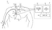
- FIG. 1is a view illustrating an application of the method according to an example embodiment of the present invention.
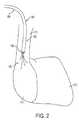
- FIG. 2is a cutaway view of a heart being accessed by a catheter infusing a fluid bolus.
- FIG. 3is a flow chart of the method according to an example embodiment of the present invention.
- FIGS. 4A-4Dshow various catheter tip positions and a corresponding user console display according to an example embodiment.
- FIG. 4Ashows a user console display when a catheter tip is positioned in a vein in the shoulder.
- FIG. 4Bshows a user console display when a catheter tip is positioned in the lower 1 ⁇ 3 of the superior vena cava.
- FIG. 4Cshows a user console display when a catheter tip is positioned in the internal jugular vein.
- FIG. 4Dshows a user console display when a catheter tip is positioned in the subclavian vein.
- FIGS. 5A-5Cshow a piezo film audio sensor.
- FIG. 5Ais a top view of a piezo film audio sensor, including cross-sectional views A-A and B-B.
- FIG. 5Bis a top view of a piezo film audio sensor with lead attachments.
- FIG. 5Cis a top view of an audio sensor within a protective layer, including cross-sectional views C-C.
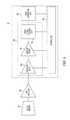
- FIG. 6is a block diagram of audio signal processing according to an example embodiment.
- FIG. 7illustrates an electrocardiogram electrode and an audio sensor communicating wirelessly with a user console according to an example embodiment.
- FIGS. 8A-8Dshow example embodiments of an audio emitting element located at the catheter tip.
- FIG. 8Ais a side view of a catheter with a flexible elongated member having a piezo audio emitting element configured at the distal portion extended through a lumen in the catheter.
- FIG. 8Bis a side view of the distal portion of the flexible elongated member having a piezo audio emitting element.
- FIG. 8Cis a side view of a catheter having a piezo film audio emitting element configured at the distal portion.
- FIG. 8Dis a side view of a piezo film element with communication elements extending proximally.
- FIG. 1shows a human body 170 with a catheter 180 inserted at a site 176 in the right arm.
- the catheter 180has a proximal portion 181 and a distal portion 182 .
- the catheter 180is a single lumen catheter, but it can have multiple lumens.
- the proximal portion 181 of the catheter 180terminates at the luer 184 .
- the distal portion 182 of the catheter 180terminates in a catheter tip 183 .
- the catheter 180can be advanced to a target location, such as the superior vena cava 173 , or some other site within the human body 170 , for delivery of fluids such as antibiotics, chemotherapy, pain medicine, nutrition, or for withdrawing blood.
- the user console 10is a device, such as a handheld tablet device, which houses the audio signal processing unit 100 and a user notification unit 110 for communicating with a user.
- Audio signals emitted from the catheter tip 183are detected by one or more audio sensors 101 , 102 or 103 , transmitted to the audio signal processing unit 100 , and processed for determining the location of a catheter tip 183 .
- the audio signal processing unit 100sends a user notification signal to the control unit 105 , which communicates with the user notification unit 110 to notify the user.
- the user notification unit 110can utilize a visual display, a sound notification, or some combination of the two for communicating with the user.
- fluidcan be rapidly injected into the lumen of catheter 180 and infused through an opening in the catheter tip 183 .
- an audio frequency sound waveis generated.
- a fluid injection technique called push pause or push stopcan be used to infuse fluid through the catheter 180 .
- the push pause techniquecreates fluid turbulence at the catheter tip 183 , generating an audio frequency sound wave.
- Increased fluid turbulencefacilitates an increase in the intensity of the generated audio frequency sound wave.
- a 10 mL syringecan be filled with 10 mL of saline and connected to the luer 184 .
- Cycles of 2 mL of saline infused over 0.5 seconds followed by a 0.5 second pausecan be repeated until the 10 mL of saline is fully infused.
- Other techniques for fluid infusionmay be used according to the present invention so that an audio frequency signal capable of detection is generated at the catheter tip.
- the viscosity of the fluid and the pressure applied to the syringe by the usercan be manipulated to increase the flow rate of the fluid.
- An increased flow ratemay also increase the intensity of the generated audio frequency sound wave, facilitating stronger detection signals.
- the target location for the catheter tip 183is just outside of the heart 172 in the lower 1 ⁇ 3 of the superior vena cava 173 .
- a first audio sensor 101is placed on the anterior side of the body 170 , positioned directly above the lower 1 ⁇ 3 of the superior vena cava 173 .
- the first audio sensor 101will detect and measure the emitted audio frequency signal.
- the audio signal processing unit 100can indicate whether or not the catheter tip 183 is the lower 1 ⁇ 3 of the superior vena cava. The determination can be made by implementing audio signal processing techniques known in the art described in further detail below, including filtering the detected audio signal to detect the saline bolus, and comparing the intensity of the detected audio signal to a baseline signal or a predetermined threshold level.
- a second audio sensor 102is placed on the skin above the internal jugular vein 174 . If, for example, the catheter tip 183 is unintentionally advanced to the internal jugular vein 174 , the second audio sensor 102 will detect the audio signal emitted from the saline bolus. Additionally, an absent or weak audio signal will be detected by the first audio sensor 101 , since the audio signal will attenuate over distance. The absent or attenuated audio signal detected by the first audio sensor 101 is an indication that the catheter tip is in the wrong position.
- the absence of a detected audio signal from both audio sensorscould indicate that the catheter tip has advanced to the subclavian vein, a malfunction occurred in one of the sensors, or that the catheter is malfunctioning, blocking the saline bolus from infusing through the opening in the catheter tip.
- a third audio sensor 103is placed on the skin above the subclavian vein 175 .
- the third audio sensor 103will detect the audio signal from the saline bolus.
- no audio signal, or a weak audio signal attenuated by distancemay be detected.
- the addition of the third sensorprovides the audio signal processing unit 100 with enough data for identifying specifically which non-target position the catheter tip is located in.
- first and second audio sensors 101 and 102can be strategically placed for comparing detected audio signals and localizing the position of the catheter tip 183 .
- the right third intercostal spaceis commonly used by medical professionals as an external reference point for locating the superior vena cava 173 .
- a first audio sensor 101can be positioned on the skin directly above the second intercostal space and a second audio sensor 102 can be positioned on the skin directly above the fourth intercostal space.
- the first and second audio sensors 101 and 102should be in alignment with each other and consequently roughly equidistant from the third intercostal space.
- the intensity of the audio signal detected from the first audio sensor 101will reach a maximum once the catheter tip 183 is directly under the second intercostal space.
- the intensity of the audio signal detected by the first audio sensor 101will decrease as the intensity of the audio signal detected by the second audio sensor 102 increases.
- the audio signal processing unit 100can compare the first and second detected audio signals for localizing the catheter tip 183 .
- a fourth audio sensorcan be placed on the skin above a right portion of the subclavian vein.
- the catheter tip 183returns down the same path from which it was inserted, for example, in a right portion of the subclavian. This could happen if for example the patient moves a lot during insertion and the catheter tip changes 180 degrees in direction, or the catheter tip become mispositioned after initial insertion.
- the audio signal processing unit 100can detect the catheter tip 183 and alert the user.
- FIG. 3a flow chart shows an example embodiment of the method according to the present invention.
- the patientmay be undergoing a procedure for catheter insertion, or maintenance of a previously inserted catheter S 1 .
- At least one audio sensor 101is placed above the patient's skin over the target area of the catheter tip 183 S 2 .
- the audio sensor 101is connected or synced to the audio signal processing unit 100 S 3 .
- Fluidis injected through the catheter 180 S 4 so that an audio frequency sound wave is generated at the catheter tip 183 .
- the audio sensor 101will detect the audio frequency sound wave generated from the fluid infusion, and the detected audio signal will be transmitted to the audio signal processing unit 100 S 5 .
- the audio signal processing unit 100processes the detected audio signal and transmits a determination regarding tip location to the user notification unit 110 S 6 .
- the user notification unit 110displays the tip location determination to the user S 7 . If the tip location is in the target location S 8 , the process has ended S 10 , as the catheter tip 183 is determined to be in the target location. If the catheter tip 183 is in a non-target location, or if the tip location cannot be determined S 8 , the user adjusts the catheter tip 183 S 9 and injects more fluid through the catheter 180 S 4 . A new audio frequency sound wave generated from the fluid infusion is detected and transmitted to the audio signal processing unit 100 S 5 .
- the audio signal processing unit 100processes the new signal, sends the determination of tip location to the user notification unit 110 S 6 , and communicates that determination to the user S 7 . If the tip is in the target location S 8 , the process ends S 10 . Otherwise, the user may repeat steps S 4 through S 9 multiple times until the catheter tip 183 is in the target location.
- the catheter tip of any cathetercan be located, regardless of length, size or manufacturer. Further, there is no need for a separate stylet component, electromagnetic detecting or emitting components, or a patient with a normal sinus rhythm. In addition, the patient is not exposed to harmful radiation, and the operator does not need special training in interpreting x-ray or ultrasound images.
- a notification signalis sent to a user notification unit 110 .
- the notification signalcan be sent either directly to the user notification unit 110 , or sent to a control unit 105 that communicates with the user notification unit 110 .
- the user notification unit 110can have a visual display for indicating when the catheter tip 183 is in proper position.
- FIGS. 4A-4Dillustrate a user notification display on the user console 10 according to an example embodiment.
- the user notification unit 110will display a red light indicating that the catheter tip 183 has been located and is not in the target location, a yellow light indicating that the catheter tip 183 has not been located, or a green light indicating that the catheter tip 183 has been located and is in the target location.
- a red light indicating that the catheter tip 183 has been located and is not in the target locatione.g., a red light indicating that the catheter tip 183 has been located and is not in the target location
- a yellow lightindicating that the catheter tip 183 has not been located
- a green lightindicating that the catheter tip 183 has been located and is in the target location.
- the audio signal processing unit 100will verify that catheter tip in the proper location, thus activating the green light.
- FIGS. 4C and 4Dshow the catheter tip 183 after being mispositioned or migrating to the internal jugular vein 174 and the subclavian vein 175 respectively, activating the red light.
- the user notification signalcan also take other forms, including an audio notification or a message display.
- FIGS. 5A-5Cshow an example embodiment of an audio sensor 101 .
- the audio sensor 101can be any audio sensor or microphone element capable of detecting audio signals emitted from within the human body.
- the audio sensoris made of piezoelectric polyvinylidene fluoride polymer film (PVDF or piezo film).
- PVDFpiezoelectric polyvinylidene fluoride polymer film
- Piezo filmis used for various acoustic applications, including contact microphones for detecting sounds emitted from within a, human body.
- Piezo filmis a flexible, lightweight, highly sensitive thin film capable of being used as an audio sensor. Piezo film is also immune to moisture, and requires no external power to function, unlike electrostatic types of audio sensors.
- FIG. 5Ashows an example embodiment of a piezo film audio sensor, with an upper electrode 151 , a lower electrode 152 , and a piece of piezo film 153 configured between the upper and lower electrodes.
- the electrodesare silver ink screen printed electrodes, which offer high conductivity, high flexibility and a thin profile.
- the upper electrode 151 and lower electrode 152overlap at the active piezo film area 154 .
- the electrical signalis proportional to the amount of elongation of the piezo film 153 .
- the piezo film sensormay be combined with a low-noise electronic preamplifier, and designed to minimize external acoustic noise.
- Transmission of detected audio signals to the audio signal processing unit 100can be accomplished by either hard wired or wireless transmission.
- lead attachments 155 and 156can be configured on the upper electrode 151 and lower electrode 152 using a number of methods, including for example, eyelets, compression clamping, rivets, crimping, eyelet holes or low temperature solders.
- the example embodiment in FIG. 5Bshows a first rivet 155 connecting a first wire 157 to the upper electrode 151 and a second rivet 156 connecting a second wire 158 to the lower electrode 152 .
- Lightweight shielded cable or twisted wire pairscan be used to connect the audio sensor 101 to the audio signal processing unit 100 while also reducing vulnerability from unwanted electromagnetic interference.
- the audio sensor 101can be designed to vibrate the piezo film through a medium, such as a pad, protective coating or protective layer 201 .
- the protective layer 201may be in direct physical contact with the skin when placed on the body.
- the protective layer 201can be made of a material compatible for measuring the audio signal, for example, rubber, a polyester reinforcing member or a thin urethane layer.
- the protective layercan also be combined with an adhesive for mounting the audio sensor on or near a surface of the skin. Additionally, shielded and low-noise elements can be used to minimize the amount of ambient noise and interference detected by the audio sensor.
- detected audio signalsare transmitted to the audio signal processing unit 100 and processed for determining whether or not the catheter tip 183 is in the target location.
- the audio frequency range associated with the sound wave generated by a saline bolusis identified.
- a high-pass filter 166 and a low-pass filter 167are implemented to remove any frequencies outside of that range, such as audio frequencies detected from breathing, blood flow, body movement or ambient environmental noise.
- a preamplifier 165can also be connected to the audio sensor to amplify the detected audio signal. Once frequencies outside of the desired frequency range are filtered out, an audio signal decision unit 168 determines if the remaining isolated frequencies representing the saline bolus are above a predetermined threshold.
- the predetermined thresholdcan be set based on various factors corresponding with the catheter tip being located in the target location, including for example a comparison to a baseline audio signal.
- the baseline audio signalcan be established by detecting an audio signal from the audio sensor before or after the saline bolus is injected.
- the detected baseline audio signalcan be transmitted to the audio signal processing unit 100 and stored in memory.
- the baseline audio signalcan also be manually programmed into the memory of the audio signal processing unit 100 .
- the above described technique audio signal processingis one of many known in the art, however, any compatible technique can be used according to the present invention.
- an electrocardiogram electrode 161can be incorporated into the protective layer 201 for tracking electrical activity of the heart.
- electrocardiogramscan be used for locating catheter tip locations near the heart by tracking the change of the P wave as the catheter is advanced from the upper 1 ⁇ 3 of the superior vena cava down to through the lower 1 ⁇ 3 of the superior vena cava, and into the right atrium 171 .
- the change in the P wave on an electrocardiogram monitorcorrelates to the position of the catheter tip, typically spiking as the catheter tip enters the right atrium 171 .
- the P waveis reduced as the catheter tip is pulled back from the entrance to the right atrium 171 .
- an electrocardiogram electrode 161is positioned in the protective layer 201 next to the first audio sensor 101 .
- the electrocardiogram electrode 161transmits detected electrocardiogram signals to the electrocardiogram signal processing unit 160 .
- the signalis processed and a control unit 105 can verify that the catheter tip location determined by the audio signal processing unit 100 is consistent with the catheter tip location determined by the electrocardiogram signal processing unit 160 .
- Transmission of the electrocardiogram signal and detected audio signalcan be by a wireless transmitter 162 .
- the wireless transmitter 162can be built into the protective layer 201 and can communicate with a wireless receiver 163 built into the user console 10 .
- the electrocardiogram electrode 161can also detect a signal before or after the saline bolus is administered for monitoring the heartbeat or establishing an electrocardiogram baseline.
- the user console 10can be a stationary unit, or a mobile unit such as a handheld device. Further, the audio signal processing unit 100 , control unit 105 , user notification unit 110 and electrocardiogram signal processing unit 115 can be implemented in hardware, software, or some combination.
- the user console 10is a handheld tablet device, and the audio sensors transmit the measured audio signals to the handheld tablet device using a wireless protocol such as Bluetooth.
- the user notification unit 110could incorporate the display of handheld tablet device to communicate with the user.
- any fluid infused from a catheter tipwill generate an audio signal.
- Other fluidsmay include heparin based solutions, including for example Lactated Ringer's solution and Hartmann's Solution.
- infusion ratesalthough a bolus or rapid infusion of fluid will improve clarity of the detected audio signal, infusion rates may vary depending on various factors including the pickup ability of the audio sensors. Further, the audio signal processing unit 100 can be programmed to compensate for changes in fluids and infusion rates.
- a method for locating a catheter tip 183 using audio detectionuses an audio emitting element positioned at the catheter tip 183 , thus no fluid infusion is required.
- a flexible elongated member 190has a proximal portion 193 and distal portion 192 , terminating in a tip 194 at the distal portion 192 .
- Proximate to the tip 194is an audio emitting element 191 , such as a piezo crystal or a piece of piezo film.
- the flexible elongated member 190can be made of a medical grade flexible material having a diameter smaller than the diameter of the lumen 198 in the catheter 180 .
- the regions along the flexible elongated member 190can vary in stiffness, depending on the application.
- the flexible elongated member 190may also be made from a guide wire like material.
- the user console 10can communicate with the audio emitting element 191 through communication elements such as conductive wire or ink that extend through the flexible elongated member 190 .
- the communication elementscan extend to the proximal portion 193 of the flexible elongated member 190 , and can be connected to an audio signal generating unit in the user console 10 .
- the audio signal generating unitcan set the audio emitting element 191 to emit an audio beacon signal at a frequency distinct from the audio frequencies of ambient noise. For example, consideration should be given to blood flow, breathing, bodily movements and ambient environmental noise. Consideration should also be given to audio sensor position and the impact that anatomical factors such as body density and bone structure will have on detection of particular beacon frequencies. According to this method, the location of any catheter tip can be located, regardless of length, size or manufacturer.
- the sound emitting elementcan be attached to the catheter.
- an audio emitting element 195such as piezo film is attached to or embedded in a wall of the catheter distal end portion 182 .
- a first and second elongated transmission element 196 and 197extend from the sound emitting element proximally through the catheter wall, exiting the catheter at its proximal end.
- the exposed communication elements at the luer 184can be connected to an audio signal generating unit in the user console 10 .
- the user console 10can thus communicate with the audio emitting element 195 to set an audio beacon signal at a distinct audio frequency.
- a saline bolus or infusion of fluid from the catheter tipis not required, since the sound emitting element acts as a beacon for the audio sensors. Further, the location of a catheter tip can be determined on initial placement and subsequent maintenance, and does not require a separately stocked stylet component.
- the kitmay include a user console, audio sensors, wired or wireless signal transmission elements, and instructions for use.
- the kitmay also include PICC catheters with or without an audio emitting element, and a stylet with an audio emitting element.
- the method according to the present inventioncan be used for procedures that target any site within the body.
- any type of catheter tipcan be located, including acute and chronic dialysis catheters, subcutaneous port catheters, and central venous catheters.
- access sitesdo not need to be in the arm. For example, for a patient with amputated arms, the access site may be in the groin or in the back.
Landscapes
- Health & Medical Sciences (AREA)
- Life Sciences & Earth Sciences (AREA)
- Engineering & Computer Science (AREA)
- Physics & Mathematics (AREA)
- Veterinary Medicine (AREA)
- Public Health (AREA)
- Biomedical Technology (AREA)
- Heart & Thoracic Surgery (AREA)
- Animal Behavior & Ethology (AREA)
- General Health & Medical Sciences (AREA)
- Biophysics (AREA)
- Medical Informatics (AREA)
- Molecular Biology (AREA)
- Surgery (AREA)
- Pathology (AREA)
- Cardiology (AREA)
- Acoustics & Sound (AREA)
- Physiology (AREA)
- Pulmonology (AREA)
- Human Computer Interaction (AREA)
- Anesthesiology (AREA)
- Hematology (AREA)
- Nuclear Medicine, Radiotherapy & Molecular Imaging (AREA)
- Radiology & Medical Imaging (AREA)
- Media Introduction/Drainage Providing Device (AREA)
Abstract
Description
Claims (3)
Priority Applications (3)
| Application Number | Priority Date | Filing Date | Title |
|---|---|---|---|
| US13/251,686US8753292B2 (en) | 2010-10-01 | 2011-10-03 | Method for locating a catheter tip using audio detection |
| US14/272,890US9351663B2 (en) | 2010-10-01 | 2014-05-08 | Method for locating a catheter tip using audio detection |
| US15/165,770US10159460B2 (en) | 2010-10-01 | 2016-05-26 | Method for locating a catheter tip using audio detection |
Applications Claiming Priority (2)
| Application Number | Priority Date | Filing Date | Title |
|---|---|---|---|
| US38867510P | 2010-10-01 | 2010-10-01 | |
| US13/251,686US8753292B2 (en) | 2010-10-01 | 2011-10-03 | Method for locating a catheter tip using audio detection |
Related Child Applications (1)
| Application Number | Title | Priority Date | Filing Date |
|---|---|---|---|
| US14/272,890ContinuationUS9351663B2 (en) | 2010-10-01 | 2014-05-08 | Method for locating a catheter tip using audio detection |
Publications (2)
| Publication Number | Publication Date |
|---|---|
| US20120083702A1 US20120083702A1 (en) | 2012-04-05 |
| US8753292B2true US8753292B2 (en) | 2014-06-17 |
Family
ID=45890398
Family Applications (3)
| Application Number | Title | Priority Date | Filing Date |
|---|---|---|---|
| US13/251,686Expired - Fee RelatedUS8753292B2 (en) | 2010-10-01 | 2011-10-03 | Method for locating a catheter tip using audio detection |
| US14/272,890Active2032-03-21US9351663B2 (en) | 2010-10-01 | 2014-05-08 | Method for locating a catheter tip using audio detection |
| US15/165,770Active2032-01-13US10159460B2 (en) | 2010-10-01 | 2016-05-26 | Method for locating a catheter tip using audio detection |
Family Applications After (2)
| Application Number | Title | Priority Date | Filing Date |
|---|---|---|---|
| US14/272,890Active2032-03-21US9351663B2 (en) | 2010-10-01 | 2014-05-08 | Method for locating a catheter tip using audio detection |
| US15/165,770Active2032-01-13US10159460B2 (en) | 2010-10-01 | 2016-05-26 | Method for locating a catheter tip using audio detection |
Country Status (1)
| Country | Link |
|---|---|
| US (3) | US8753292B2 (en) |
Cited By (2)
| Publication number | Priority date | Publication date | Assignee | Title |
|---|---|---|---|---|
| US20170304571A1 (en)* | 2014-10-20 | 2017-10-26 | Ohio State Innovation Foundation | Intubation with audiovibratory guidance |
| US10092215B2 (en) | 2016-06-29 | 2018-10-09 | Piccolo Medical Inc. | Devices and methods for vascular navigation, assessment and/or diagnosis |
Families Citing this family (32)
| Publication number | Priority date | Publication date | Assignee | Title |
|---|---|---|---|---|
| US8784336B2 (en) | 2005-08-24 | 2014-07-22 | C. R. Bard, Inc. | Stylet apparatuses and methods of manufacture |
| US9649048B2 (en) | 2007-11-26 | 2017-05-16 | C. R. Bard, Inc. | Systems and methods for breaching a sterile field for intravascular placement of a catheter |
| US10524691B2 (en) | 2007-11-26 | 2020-01-07 | C. R. Bard, Inc. | Needle assembly including an aligned magnetic element |
| US10751509B2 (en) | 2007-11-26 | 2020-08-25 | C. R. Bard, Inc. | Iconic representations for guidance of an indwelling medical device |
| ES2465915T3 (en) | 2007-11-26 | 2014-06-09 | C.R. Bard, Inc. | Integrated system for intravascular catheter placement |
| US8781555B2 (en) | 2007-11-26 | 2014-07-15 | C. R. Bard, Inc. | System for placement of a catheter including a signal-generating stylet |
| US9521961B2 (en) | 2007-11-26 | 2016-12-20 | C. R. Bard, Inc. | Systems and methods for guiding a medical instrument |
| US9901714B2 (en) | 2008-08-22 | 2018-02-27 | C. R. Bard, Inc. | Catheter assembly including ECG sensor and magnetic assemblies |
| US9532724B2 (en) | 2009-06-12 | 2017-01-03 | Bard Access Systems, Inc. | Apparatus and method for catheter navigation using endovascular energy mapping |
| EP2464407A4 (en) | 2009-08-10 | 2014-04-02 | Bard Access Systems Inc | Devices and methods for endovascular electrography |
| WO2011097312A1 (en) | 2010-02-02 | 2011-08-11 | C.R. Bard, Inc. | Apparatus and method for catheter navigation and tip location |
| EP4122385A1 (en) | 2010-05-28 | 2023-01-25 | C. R. Bard, Inc. | Insertion guidance system for needles and medical components |
| EP2912999B1 (en) | 2010-05-28 | 2022-06-29 | C. R. Bard, Inc. | Apparatus for use with needle insertion guidance system |
| BR112013002431B1 (en) | 2010-08-20 | 2021-06-29 | C.R. Bard, Inc | SYSTEM FOR RECONFIRMING THE POSITION OF A CATHETER INSIDE A PATIENT |
| US8753292B2 (en)* | 2010-10-01 | 2014-06-17 | Angiodynamics, Inc. | Method for locating a catheter tip using audio detection |
| EP2637568B1 (en) | 2010-11-08 | 2017-04-12 | Vasonova, Inc. | Endovascular navigation system |
| US9707363B2 (en) | 2012-03-29 | 2017-07-18 | Sonarmed Inc. | System and method for use of acoustic reflectometry information in ventilation devices |
| EP2846701A4 (en) | 2012-05-07 | 2016-01-27 | Vasonova Inc | Right atrium indicator |
| WO2015120256A2 (en) | 2014-02-06 | 2015-08-13 | C.R. Bard, Inc. | Systems and methods for guidance and placement of an intravascular device |
| US20150282734A1 (en) | 2014-04-08 | 2015-10-08 | Timothy Schweikert | Medical device placement system and a method for its use |
| US10603114B2 (en)* | 2014-04-17 | 2020-03-31 | Koninklijke Philips N.V. | Method and system for detecting a fast moving surgical device |
| US10973584B2 (en) | 2015-01-19 | 2021-04-13 | Bard Access Systems, Inc. | Device and method for vascular access |
| AU2016238177B2 (en)* | 2015-03-26 | 2021-02-18 | Covidien Lp | Improved acoustical guidance and monitoring system |
| WO2016187456A1 (en)* | 2015-05-20 | 2016-11-24 | Gravitas Medical, Inc. | Methods and apparatus for guiding medical care based on sensor data from the gastrointestinal tract |
| WO2016210325A1 (en) | 2015-06-26 | 2016-12-29 | C.R. Bard, Inc. | Connector interface for ecg-based catheter positioning system |
| US11000207B2 (en) | 2016-01-29 | 2021-05-11 | C. R. Bard, Inc. | Multiple coil system for tracking a medical device |
| EP3463061B1 (en) | 2016-05-31 | 2021-04-07 | Sonarmed Inc. | Acoustic reflectometry device in catheters |
| US10835715B2 (en)* | 2016-08-08 | 2020-11-17 | Angiodynamics Va Llc | System and method for locating a catheter tip |
| WO2019028420A1 (en) | 2017-08-04 | 2019-02-07 | Sonarmed Inc. | Acoustic guided suction systems, devices, and methods |
| US10992079B2 (en) | 2018-10-16 | 2021-04-27 | Bard Access Systems, Inc. | Safety-equipped connection systems and methods thereof for establishing electrical connections |
| CN110141409B (en)* | 2019-06-25 | 2021-08-20 | 中国医学科学院阜外医院 | A guide wire assembly for the delivery of a bifurcated stent-graft |
| WO2022055806A1 (en) | 2020-09-08 | 2022-03-17 | Piccolo Medical, Inc. | Devices and methods for vascular navigation, assessment, treatment and/or diagnosis |
Citations (46)
| Publication number | Priority date | Publication date | Assignee | Title |
|---|---|---|---|---|
| US4274423A (en) | 1977-12-15 | 1981-06-23 | Kabushiki Kaisha Toyota Chuo Kenkyusho | Catheter tip pressure transducer |
| US4821731A (en) | 1986-04-25 | 1989-04-18 | Intra-Sonix, Inc. | Acoustic image system and method |
| US4905698A (en) | 1988-09-13 | 1990-03-06 | Pharmacia Deltec Inc. | Method and apparatus for catheter location determination |
| US4947852A (en) | 1988-10-05 | 1990-08-14 | Cardiometrics, Inc. | Apparatus and method for continuously measuring volumetric blood flow using multiple transducer and catheter for use therewith |
| US4951677A (en) | 1988-03-21 | 1990-08-28 | Prutech Research And Development Partnership Ii | Acoustic imaging catheter and the like |
| US5038789A (en) | 1989-09-28 | 1991-08-13 | Frazin Leon J | Method and device for doppler-guided retrograde catheterization |
| US5042486A (en) | 1989-09-29 | 1991-08-27 | Siemens Aktiengesellschaft | Catheter locatable with non-ionizing field and method for locating same |
| US5078714A (en) | 1990-03-02 | 1992-01-07 | Jefferson Katims | Method and apparatus for placement of a probe in the body and the medical procedure for guiding and locating a catheter or probe in the body |
| US5099845A (en) | 1989-05-24 | 1992-03-31 | Micronix Pty Ltd. | Medical instrument location means |
| US5131397A (en) | 1990-09-07 | 1992-07-21 | Boston Scientific Corp. | Imaging system for producing ultrasonic images and insonifier for such systems |
| US5156157A (en) | 1991-03-08 | 1992-10-20 | Telectronics Pacing Systems, Inc. | Catheter-mounted doppler ultrasound transducer and signal processor |
| US5161536A (en) | 1991-03-22 | 1992-11-10 | Catheter Technology | Ultrasonic position indicating apparatus and methods |
| US5280786A (en) | 1992-01-21 | 1994-01-25 | Fiberoptic Sensor Technologies, Inc. | Fiberoptic blood pressure and oxygenation sensor |
| US5386828A (en) | 1991-12-23 | 1995-02-07 | Sims Deltec, Inc. | Guide wire apparatus with location sensing member |
| US5425367A (en) | 1991-09-04 | 1995-06-20 | Navion Biomedical Corporation | Catheter depth, position and orientation location system |
| US5526820A (en) | 1994-09-19 | 1996-06-18 | Myelotec, Inc. | Catheter with integral pressure sensor |
| US5592939A (en) | 1995-06-14 | 1997-01-14 | Martinelli; Michael A. | Method and system for navigating a catheter probe |
| US5622169A (en) | 1993-09-14 | 1997-04-22 | University Of Washington | Apparatus and method for locating a medical tube in the body of a patient |
| US5645065A (en) | 1991-09-04 | 1997-07-08 | Navion Biomedical Corporation | Catheter depth, position and orientation location system |
| US5666958A (en) | 1995-04-06 | 1997-09-16 | Rothenberg; Peter M. | Interface module for electrically connecting medical equipment |
| US5727553A (en) | 1996-03-25 | 1998-03-17 | Saad; Saad A. | Catheter with integral electromagnetic location identification device |
| US5727552A (en) | 1996-01-11 | 1998-03-17 | Medtronic, Inc. | Catheter and electrical lead location system |
| US5749835A (en) | 1994-09-06 | 1998-05-12 | Sims Deltec, Inc. | Method and apparatus for location of a catheter tip |
| US5843076A (en) | 1995-06-12 | 1998-12-01 | Cordis Webster, Inc. | Catheter with an electromagnetic guidance sensor |
| US5899860A (en) | 1996-09-12 | 1999-05-04 | Siemens Elema Ab | Method and device for determining the position of a catheter inside the body of a patient |
| US5944023A (en) | 1995-12-07 | 1999-08-31 | Sims Deltec, Inc. | Systems and methods for determining the location of an implanted device including a magnet |
| US5983126A (en) | 1995-11-22 | 1999-11-09 | Medtronic, Inc. | Catheter location system and method |
| US6038468A (en) | 1997-09-26 | 2000-03-14 | Roke Manor Research Ltd. | Catheter localisation system |
| US6052610A (en) | 1998-01-09 | 2000-04-18 | International Business Machines Corporation | Magnetic catheter tracker and method therefor |
| US6061588A (en) | 1998-09-29 | 2000-05-09 | Advanced Cardiovascular Systems, Inc. | Catheter apparatus for positioning a wire |
| US6226546B1 (en) | 1997-09-24 | 2001-05-01 | Roke Manor Research Limited | Catheter localization system and method for performing medical diagnostics |
| US6230042B1 (en) | 1998-03-25 | 2001-05-08 | Siemens Elema Ab | Method and arrangement for determining the location of a catheter within an animal body |
| US6261247B1 (en) | 1998-12-31 | 2001-07-17 | Ball Semiconductor, Inc. | Position sensing system |
| US6298261B1 (en) | 1997-11-15 | 2001-10-02 | Roke Manor Research Limited | Catheter tracking system |
| US6304769B1 (en) | 1997-10-16 | 2001-10-16 | The Regents Of The University Of California | Magnetically directable remote guidance systems, and methods of use thereof |
| US6618612B1 (en) | 1996-02-15 | 2003-09-09 | Biosense, Inc. | Independently positionable transducers for location system |
| US6629987B1 (en) | 1999-07-30 | 2003-10-07 | C. R. Bard, Inc. | Catheter positioning systems |
| US6690963B2 (en) | 1995-01-24 | 2004-02-10 | Biosense, Inc. | System for determining the location and orientation of an invasive medical instrument |
| US6705319B1 (en) | 2000-05-26 | 2004-03-16 | Purdue Research Foundation | Miniature acoustical guidance and monitoring system for tube or catheter placement |
| US6711429B1 (en) | 1998-09-24 | 2004-03-23 | Super Dimension Ltd. | System and method for determining the location of a catheter during an intra-body medical procedure |
| US6741883B2 (en) | 2002-02-28 | 2004-05-25 | Houston Stereotactic Concepts, Inc. | Audible feedback from positional guidance systems |
| US20050157888A1 (en) | 2004-01-13 | 2005-07-21 | Health & Life Co., Ltd. | Electronic stethoscope with piezo-electrical film contact microphone |
| US6977504B2 (en) | 2003-12-31 | 2005-12-20 | Calypso Medical Technologies, Inc. | Receiver used in marker localization sensing system using coherent detection |
| US20080097232A1 (en) | 2006-10-23 | 2008-04-24 | Rothenberg Peter M | Method of locating the tip of a central venous catheter |
| US8197494B2 (en)* | 2006-09-08 | 2012-06-12 | Corpak Medsystems, Inc. | Medical device position guidance system with wireless connectivity between a noninvasive device and an invasive device |
| US8597193B2 (en)* | 2005-05-06 | 2013-12-03 | Vasonova, Inc. | Apparatus and method for endovascular device guiding and positioning using physiological parameters |
Family Cites Families (6)
| Publication number | Priority date | Publication date | Assignee | Title |
|---|---|---|---|---|
| US6409674B1 (en)* | 1998-09-24 | 2002-06-25 | Data Sciences International, Inc. | Implantable sensor with wireless communication |
| GB0215710D0 (en)* | 2002-07-05 | 2002-08-14 | Isis Innovation | Diagnostic method |
| CA2464634A1 (en)* | 2004-04-16 | 2005-10-16 | Andromed Inc. | Pap estimator |
| BRPI0909542B8 (en)* | 2008-05-29 | 2021-06-22 | Itamar Medical Ltd | method of examining an individual in search of a special physiological condition through a technique that uses sounds generated by the individual and perceived at a pre-defined distance from the location of the individual's body sound generation and apparatus to examine an individual in search of a special physiological condition through a technique that uses sounds generated by the individual and perceived at a pre-defined distance from the location of the individual's body sound generation |
| US9752914B2 (en)* | 2008-06-24 | 2017-09-05 | Fize Research Ltd | Measuring apparatus system and method |
| US8753292B2 (en)* | 2010-10-01 | 2014-06-17 | Angiodynamics, Inc. | Method for locating a catheter tip using audio detection |
- 2011
- 2011-10-03USUS13/251,686patent/US8753292B2/ennot_activeExpired - Fee Related
- 2014
- 2014-05-08USUS14/272,890patent/US9351663B2/enactiveActive
- 2016
- 2016-05-26USUS15/165,770patent/US10159460B2/enactiveActive
Patent Citations (49)
| Publication number | Priority date | Publication date | Assignee | Title |
|---|---|---|---|---|
| US4274423A (en) | 1977-12-15 | 1981-06-23 | Kabushiki Kaisha Toyota Chuo Kenkyusho | Catheter tip pressure transducer |
| US4821731A (en) | 1986-04-25 | 1989-04-18 | Intra-Sonix, Inc. | Acoustic image system and method |
| US4951677A (en) | 1988-03-21 | 1990-08-28 | Prutech Research And Development Partnership Ii | Acoustic imaging catheter and the like |
| US4905698A (en) | 1988-09-13 | 1990-03-06 | Pharmacia Deltec Inc. | Method and apparatus for catheter location determination |
| US4905698B1 (en) | 1988-09-13 | 1991-10-01 | Pharmacia Deltec Inc | |
| US4947852A (en) | 1988-10-05 | 1990-08-14 | Cardiometrics, Inc. | Apparatus and method for continuously measuring volumetric blood flow using multiple transducer and catheter for use therewith |
| US5099845A (en) | 1989-05-24 | 1992-03-31 | Micronix Pty Ltd. | Medical instrument location means |
| US5038789A (en) | 1989-09-28 | 1991-08-13 | Frazin Leon J | Method and device for doppler-guided retrograde catheterization |
| US5042486A (en) | 1989-09-29 | 1991-08-27 | Siemens Aktiengesellschaft | Catheter locatable with non-ionizing field and method for locating same |
| US5078714A (en) | 1990-03-02 | 1992-01-07 | Jefferson Katims | Method and apparatus for placement of a probe in the body and the medical procedure for guiding and locating a catheter or probe in the body |
| US5131397A (en) | 1990-09-07 | 1992-07-21 | Boston Scientific Corp. | Imaging system for producing ultrasonic images and insonifier for such systems |
| US5156157A (en) | 1991-03-08 | 1992-10-20 | Telectronics Pacing Systems, Inc. | Catheter-mounted doppler ultrasound transducer and signal processor |
| US5161536A (en) | 1991-03-22 | 1992-11-10 | Catheter Technology | Ultrasonic position indicating apparatus and methods |
| US5425367A (en) | 1991-09-04 | 1995-06-20 | Navion Biomedical Corporation | Catheter depth, position and orientation location system |
| US5645065A (en) | 1991-09-04 | 1997-07-08 | Navion Biomedical Corporation | Catheter depth, position and orientation location system |
| US5386828A (en) | 1991-12-23 | 1995-02-07 | Sims Deltec, Inc. | Guide wire apparatus with location sensing member |
| US5280786A (en) | 1992-01-21 | 1994-01-25 | Fiberoptic Sensor Technologies, Inc. | Fiberoptic blood pressure and oxygenation sensor |
| US5622169A (en) | 1993-09-14 | 1997-04-22 | University Of Washington | Apparatus and method for locating a medical tube in the body of a patient |
| US6112111A (en) | 1994-09-06 | 2000-08-29 | Sims Deltec, Inc. | Method and apparatus for location of a catheter tip |
| US5749835A (en) | 1994-09-06 | 1998-05-12 | Sims Deltec, Inc. | Method and apparatus for location of a catheter tip |
| US5526820A (en) | 1994-09-19 | 1996-06-18 | Myelotec, Inc. | Catheter with integral pressure sensor |
| US6690963B2 (en) | 1995-01-24 | 2004-02-10 | Biosense, Inc. | System for determining the location and orientation of an invasive medical instrument |
| US5666958A (en) | 1995-04-06 | 1997-09-16 | Rothenberg; Peter M. | Interface module for electrically connecting medical equipment |
| US5843076A (en) | 1995-06-12 | 1998-12-01 | Cordis Webster, Inc. | Catheter with an electromagnetic guidance sensor |
| US5592939A (en) | 1995-06-14 | 1997-01-14 | Martinelli; Michael A. | Method and system for navigating a catheter probe |
| US5983126A (en) | 1995-11-22 | 1999-11-09 | Medtronic, Inc. | Catheter location system and method |
| US5944023A (en) | 1995-12-07 | 1999-08-31 | Sims Deltec, Inc. | Systems and methods for determining the location of an implanted device including a magnet |
| US5727552A (en) | 1996-01-11 | 1998-03-17 | Medtronic, Inc. | Catheter and electrical lead location system |
| US6618612B1 (en) | 1996-02-15 | 2003-09-09 | Biosense, Inc. | Independently positionable transducers for location system |
| US5727553A (en) | 1996-03-25 | 1998-03-17 | Saad; Saad A. | Catheter with integral electromagnetic location identification device |
| US5899860A (en) | 1996-09-12 | 1999-05-04 | Siemens Elema Ab | Method and device for determining the position of a catheter inside the body of a patient |
| US6226546B1 (en) | 1997-09-24 | 2001-05-01 | Roke Manor Research Limited | Catheter localization system and method for performing medical diagnostics |
| US6038468A (en) | 1997-09-26 | 2000-03-14 | Roke Manor Research Ltd. | Catheter localisation system |
| US6304769B1 (en) | 1997-10-16 | 2001-10-16 | The Regents Of The University Of California | Magnetically directable remote guidance systems, and methods of use thereof |
| US6298261B1 (en) | 1997-11-15 | 2001-10-02 | Roke Manor Research Limited | Catheter tracking system |
| US6052610A (en) | 1998-01-09 | 2000-04-18 | International Business Machines Corporation | Magnetic catheter tracker and method therefor |
| US6230042B1 (en) | 1998-03-25 | 2001-05-08 | Siemens Elema Ab | Method and arrangement for determining the location of a catheter within an animal body |
| US6711429B1 (en) | 1998-09-24 | 2004-03-23 | Super Dimension Ltd. | System and method for determining the location of a catheter during an intra-body medical procedure |
| US6061588A (en) | 1998-09-29 | 2000-05-09 | Advanced Cardiovascular Systems, Inc. | Catheter apparatus for positioning a wire |
| US6261247B1 (en) | 1998-12-31 | 2001-07-17 | Ball Semiconductor, Inc. | Position sensing system |
| US6629987B1 (en) | 1999-07-30 | 2003-10-07 | C. R. Bard, Inc. | Catheter positioning systems |
| US6705319B1 (en) | 2000-05-26 | 2004-03-16 | Purdue Research Foundation | Miniature acoustical guidance and monitoring system for tube or catheter placement |
| US6741883B2 (en) | 2002-02-28 | 2004-05-25 | Houston Stereotactic Concepts, Inc. | Audible feedback from positional guidance systems |
| US6977504B2 (en) | 2003-12-31 | 2005-12-20 | Calypso Medical Technologies, Inc. | Receiver used in marker localization sensing system using coherent detection |
| US20050157888A1 (en) | 2004-01-13 | 2005-07-21 | Health & Life Co., Ltd. | Electronic stethoscope with piezo-electrical film contact microphone |
| US8597193B2 (en)* | 2005-05-06 | 2013-12-03 | Vasonova, Inc. | Apparatus and method for endovascular device guiding and positioning using physiological parameters |
| US8197494B2 (en)* | 2006-09-08 | 2012-06-12 | Corpak Medsystems, Inc. | Medical device position guidance system with wireless connectivity between a noninvasive device and an invasive device |
| US20080097232A1 (en) | 2006-10-23 | 2008-04-24 | Rothenberg Peter M | Method of locating the tip of a central venous catheter |
| US8512256B2 (en)* | 2006-10-23 | 2013-08-20 | Bard Access Systems, Inc. | Method of locating the tip of a central venous catheter |
Non-Patent Citations (6)
| Title |
|---|
| Discover Sherlock* | Sherlock* II Tip Location System | Bard Access Systems; www.bardaccess.com/discoversherlock//sherlock-system.php, Jul. 17, 2009. |
| Discover Sherlock* | Sherlock* II Tip Location System | Bard Access Systems; www.bardaccess.com/discoversherlock//sherlock—system.php, Jul. 17, 2009. |
| PICC Tip Location: Hot Topics: UI Community HomeCare: University of Iowa Health Care; www.uihealthcare.com/depts/uihomecare/hottopics/picctiplocation.html; Jul. 17, 2009. |
| Piezo Film Sensors Technical Manual; Measurement Specialties; P/N 1005663-1 Rev B; Apr. 2, 1999. |
| Richard H. Brown, The Piezo Solution for Vital Signs Monitoring, Medical Design Technology, Mar. 11, 2008, pp. 36-40. |
| Tip Location of Peripherally Inserted Central Catheters, Journal of Vascular Access Devices, Summer 1998. |
Cited By (5)
| Publication number | Priority date | Publication date | Assignee | Title |
|---|---|---|---|---|
| US20170304571A1 (en)* | 2014-10-20 | 2017-10-26 | Ohio State Innovation Foundation | Intubation with audiovibratory guidance |
| US10610655B2 (en)* | 2014-10-20 | 2020-04-07 | Ohio State Innovation Foundation | Intubation with audiovibratory guidance |
| US10092215B2 (en) | 2016-06-29 | 2018-10-09 | Piccolo Medical Inc. | Devices and methods for vascular navigation, assessment and/or diagnosis |
| US11826137B2 (en) | 2016-06-29 | 2023-11-28 | Piccolo Medical, Inc. | Devices and methods for vascular navigation, assessment and/or diagnosis |
| US12433505B2 (en) | 2016-06-29 | 2025-10-07 | Piccolo Medical, Inc. | Devices and methods for vascular navigation, assessment and/or diagnosis |
Also Published As
| Publication number | Publication date |
|---|---|
| US10159460B2 (en) | 2018-12-25 |
| US20160270759A1 (en) | 2016-09-22 |
| US20120083702A1 (en) | 2012-04-05 |
| US20140249428A1 (en) | 2014-09-04 |
| US9351663B2 (en) | 2016-05-31 |
Similar Documents
| Publication | Publication Date | Title |
|---|---|---|
| US10159460B2 (en) | Method for locating a catheter tip using audio detection | |
| US9033889B2 (en) | Methods, assemblies, and devices for positioning a catheter tip using an ultrasonic imaging system | |
| US20220409238A1 (en) | Cardiac pacing | |
| JP6405090B2 (en) | Medical system for tracking the position of a medical device within a patient's vasculature and method for operating the medical system | |
| US10098999B2 (en) | Apparatus and method for the vibratory stimulation of at least one portion of a vascular access device for its monitoring | |
| US8000771B2 (en) | Method and apparatus for catheterization by detecting signals indicating proximity to anatomical features | |
| JP2011512997A (en) | Pressure sensing catheter | |
| WO2003077759A1 (en) | Catheter with integrated signal-processing device | |
| WO2009137262A3 (en) | Systems and methods for breaching a sterile field for intravascular placement of a catheter | |
| JP2013518676A (en) | Apparatus and method for locating catheter navigation and tip | |
| CN102085117A (en) | Probe data mapping using contact information | |
| US12295717B2 (en) | Intravascular sensing devices having flexible tip structure | |
| US10874830B2 (en) | Smart torquer and methods of using the same | |
| US10835715B2 (en) | System and method for locating a catheter tip | |
| CN113143220A (en) | Diagnostic systems and methods including temperature sensing vascular devices | |
| US20250261993A1 (en) | Smart Torquer and Methods of Using the Same | |
| JP2019532701A (en) | Resonance localization system and method for locating catheter tip | |
| JP2024518346A (en) | Magnetically trackable stylet and method thereof | |
| EP3883487B1 (en) | Ablation catheter with stacked circuit assembly | |
| WO2015034609A1 (en) | Device for utilizing transmission ultrasonography to enable ultrasound-guided placement of central venous catheters | |
| US20220249004A1 (en) | Apparatus for accurately positioning an endocaval lead | |
| CN220158353U (en) | Magnetic tracking stylet | |
| US20240033494A1 (en) | Apparatus for Accurately Positioning an Endocaval Lead | |
| CN217469560U (en) | Wireless medical instrument power supply system | |
| US20220226609A1 (en) | System and Method for Medical Device Position Guidance |
Legal Events
| Date | Code | Title | Description |
|---|---|---|---|
| AS | Assignment | Owner name:ANGIODYNAMICS, INC., NEW YORK Free format text:ASSIGNMENT OF ASSIGNORS INTEREST;ASSIGNORS:INGOLD, JAMES E., JR.;CASEY, THOMAS VINCENT, II;NENTWICK, BRIAN F.;SIGNING DATES FROM 20110929 TO 20110930;REEL/FRAME:027006/0727 | |
| AS | Assignment | Owner name:JPMORGAN CHASE BANK, N.A., AS ADMINISTRATIVE AGENT Free format text:SECURITY AGREEMENT;ASSIGNOR:ANGIODYNAMICS, INC.;REEL/FRAME:028260/0329 Effective date:20120522 | |
| AS | Assignment | Owner name:JPMORGAN CHASE BANK, N.A., AS ADMINISTRATIVE AGENT, ILLINOIS Free format text:SECURITY AGREEMENT;ASSIGNOR:ANGIODYNAMICS, INC.;REEL/FRAME:031315/0720 Effective date:20130919 Owner name:ANGIODYNAMICS, INC., NEW YORK Free format text:RELEASE BY SECURED PARTY;ASSIGNOR:JPMORGAN CHASE BANK N.A., AS ADMINISTRATIVE AGENT;REEL/FRAME:031315/0361 Effective date:20130919 Owner name:JPMORGAN CHASE BANK, N.A., AS ADMINISTRATIVE AGENT Free format text:SECURITY AGREEMENT;ASSIGNOR:ANGIODYNAMICS, INC.;REEL/FRAME:031315/0720 Effective date:20130919 | |
| STCF | Information on status: patent grant | Free format text:PATENTED CASE | |
| AS | Assignment | Owner name:JPMORGAN CHASE BANK, N.A., AS ADMINISTRATIVE AGENT, ILLINOIS Free format text:SECURITY INTEREST;ASSIGNOR:ANGIODYNAMICS, INC.;REEL/FRAME:040613/0049 Effective date:20161107 Owner name:JPMORGAN CHASE BANK, N.A., AS ADMINISTRATIVE AGENT Free format text:SECURITY INTEREST;ASSIGNOR:ANGIODYNAMICS, INC.;REEL/FRAME:040613/0049 Effective date:20161107 | |
| AS | Assignment | Owner name:ANGIODYNAMICS, INC., NEW YORK Free format text:RELEASE BY SECURED PARTY;ASSIGNOR:JPMORGAN CHASE BANK, N.A., AS ADMINISTRATIVE AGENT;REEL/FRAME:040688/0540 Effective date:20161107 | |
| MAFP | Maintenance fee payment | Free format text:PAYMENT OF MAINTENANCE FEE, 4TH YEAR, LARGE ENTITY (ORIGINAL EVENT CODE: M1551) Year of fee payment:4 | |
| AS | Assignment | Owner name:JPMORGAN CHASE BANK, N.A., AS ADMINISTRATIVE AGENT Free format text:CONFIRMATORY GRANT OF SECURITY INTEREST IN UNITED STATES PATENTS;ASSIGNOR:ANGIODYNAMICS, INC.;REEL/FRAME:049371/0657 Effective date:20190603 Owner name:JPMORGAN CHASE BANK, N.A., AS ADMINISTRATIVE AGENT, ILLINOIS Free format text:CONFIRMATORY GRANT OF SECURITY INTEREST IN UNITED STATES PATENTS;ASSIGNOR:ANGIODYNAMICS, INC.;REEL/FRAME:049371/0657 Effective date:20190603 | |
| FEPP | Fee payment procedure | Free format text:MAINTENANCE FEE REMINDER MAILED (ORIGINAL EVENT CODE: REM.); ENTITY STATUS OF PATENT OWNER: LARGE ENTITY | |
| LAPS | Lapse for failure to pay maintenance fees | Free format text:PATENT EXPIRED FOR FAILURE TO PAY MAINTENANCE FEES (ORIGINAL EVENT CODE: EXP.); ENTITY STATUS OF PATENT OWNER: LARGE ENTITY | |
| STCH | Information on status: patent discontinuation | Free format text:PATENT EXPIRED DUE TO NONPAYMENT OF MAINTENANCE FEES UNDER 37 CFR 1.362 | |
| FP | Lapsed due to failure to pay maintenance fee | Effective date:20220617 | |
| AS | Assignment | Owner name:ANGIODYNAMICS, INC., NEW YORK Free format text:RELEASE BY SECURED PARTY;ASSIGNOR:JPMORGAN CHASE BANK, N.A., AS ADMINISTRATIVE AGENT;REEL/FRAME:061363/0446 Effective date:20220830 |